Embed Size (px)
Citation preview

NASA IXO Mission Concept Jean Grady / GSFC IXO NASA Project Manager
IXO Science Meeting/ January 28, 2009 Goddard Space Flight Center
IXO Science Mtg / January 28, 2009 Mission Concept-2
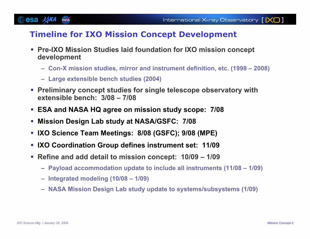
Timeline for IXO Mission Concept Development
Pre-IXO Mission Studies laid foundation for IXO mission concept development
– Con-X mission studies, mirror and instrument definition, etc. (1998 – 2008) – Large extensible bench studies (2004)
Preliminary concept studies for single telescope observatory with extensible bench: 3/08 – 7/08
ESA and NASA HQ agree on mission study scope: 7/08 Mission Design Lab study at NASA/GSFC: 7/08 IXO Science Team Meetings: 8/08 (GSFC); 9/08 (MPE) IXO Coordination Group defines instrument set: 11/09 Refine and add detail to mission concept: 10/09 – 1/09
– Payload accommodation update to include all instruments (11/08 – 1/09) – Integrated modeling (10/08 – 1/09) – NASA Mission Design Lab study update to systems/subsystems (1/09)

IXO Science Mtg / January 28, 2009 Mission Concept-3
Mission Overview
Single Mirror Configuration – 3.4 m dia mirror with a 20 m focal length
– Part of the metering structure is extensible
Mission Life and Sizing – Class B Mission: no performance
degradation w/ single point failure
– Mission Life: 5 years required; consumables sized for 10 years
Launch and Orbit Insertion – Launch on an Atlas V 551 medium fairing or
Ariane 5 in 2020
– Observatory Dry Mass is ~6100 kg (w/ 30% contingency) within capability of Atlas V or Ariane 5
– Direct launch into “zero Insertion delta-v” L2 orbit
– 100 day cruise
Mission Orbit – L2 800,000 km semi-major axis halo orbit
Earth- L2 Distance 1.5 x 10⁶ km
L2
Lunar Orbit
E
Earth-Sun angle between 7 and 34º
Max Range 1.8 x 10⁶ km
L2 Orbit ~800,000 km radius, ~180 day period
L2 Transfer Trajectory
To Sun
Courtesy - JWST

IXO Science Mtg / January 28, 2009 Mission Concept-4
IXO Payload
Flight Mirror Assembly (FMA)
– Highly nested grazing incidence optics
Instruments
– X-ray Micro-calorimeter Spectrometer (XMS)
– X-ray Grating Spectrometer (XGS)
– Wide Field Imager (WFI) and Hard X-ray Imager (HXI)
– X-ray Polarimeter (X-POL)
– High Time Resolution Spectrometer (HTRS)
XMS, WFI/HXI, XPOL and HTRS observe one at a time by being inserted into focal plane via a Moveable Instrument Platform (MIP)
– 4 Science Operational Modes
– XGS always operational
Flight Mirror Assembly
XMS
Representative Gratings
WFI/HXI
Moveable Instrument Platform (MIP)
~ 3 m
HTRS
XPOL
20 m

IXO Science Mtg / January 28, 2009 Mission Concept-5
Science Modes
Mode 1 Mode 2 Mode 3 Mode 4
Instrument Operations
Science XMS, XGS WFI, HXI, XGS X-Pol, XGS HTRS, XGS
Standby WFI, HXI, X-Pol, HTRS
XMS, X-Pol, HTRS
WFI, HXI, HTRS, XMS
WFI, HXI, XMS, X-Pol
Percent time for each Mode 40% 40% 10% 10%
Observation Duration (hours)
Average 10 hours
Minimum 30 minutes
Peak 48 hours
Instrument Operation/Science Mode Summary
4 Science Modes defined – One Science Mode for each instrument location on Movable Instrument
Platform (MIP)
– XGS operates during all Science Modes
– Instruments that are not conducting science are in placed in Standby
IXO Science Mtg / January 28, 2009 Mission Concept-6
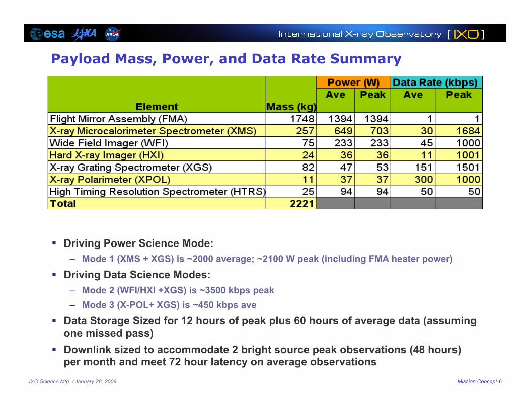
Payload Mass, Power, and Data Rate Summary
Driving Power Science Mode: – Mode 1 (XMS + XGS) is ~2000 average; ~2100 W peak (including FMA heater power)
Driving Data Science Modes: – Mode 2 (WFI/HXI +XGS) is ~3500 kbps peak – Mode 3 (X-POL+ XGS) is ~450 kbps ave
Data Storage Sized for 12 hours of peak plus 60 hours of average data (assuming one missed pass)
Downlink sized to accommodate 2 bright source peak observations (48 hours) per month and meet 72 hour latency on average observations

IXO Science Mtg / January 28, 2009 Mission Concept-7
Deployment Module
Instrument Module
Spacecraft Module
Optics Module
12.1 m
Deployed IXO Configuration
Stowed IXO Configuration
NASA Mission Design
10.1 m
IXO Science Mtg / January 28, 2009 Mission Concept-8
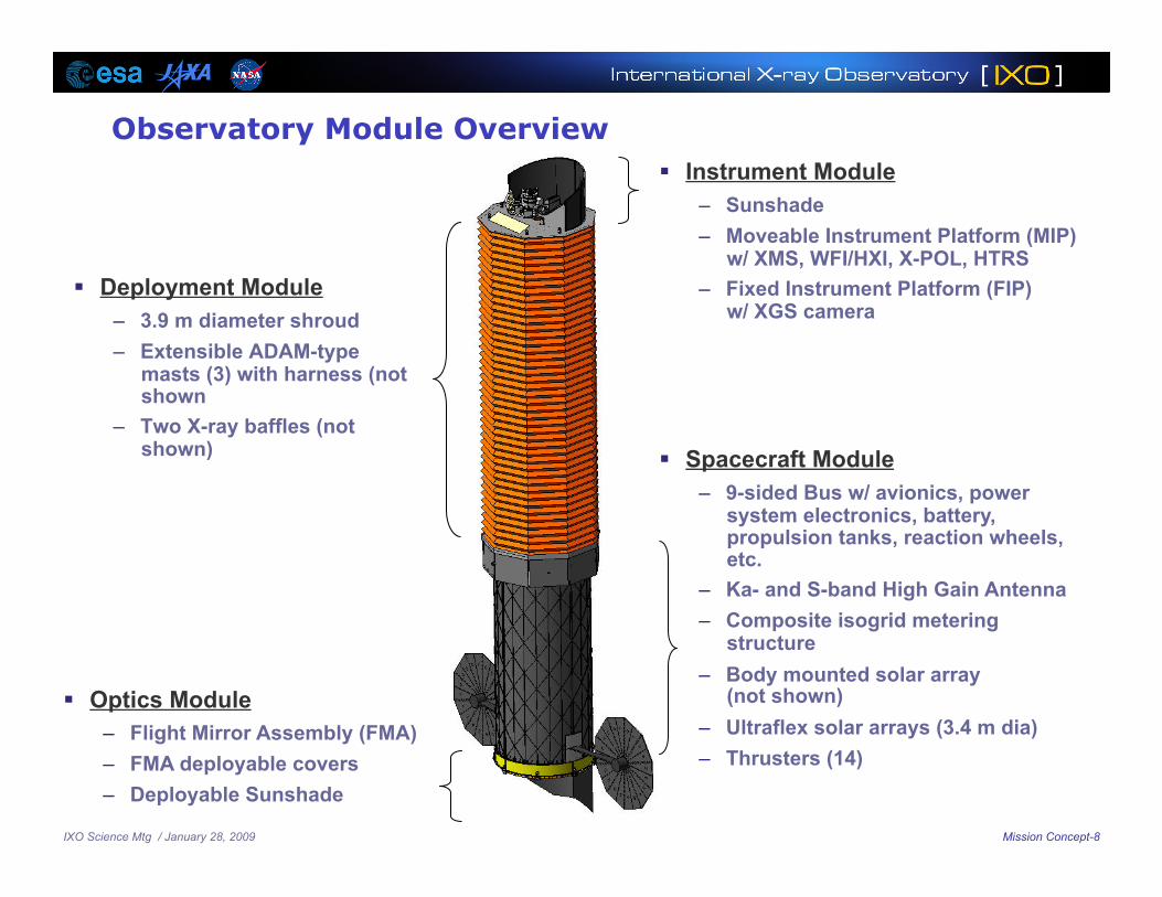
Observatory Module Overview
Deployment Module – 3.9 m diameter shroud – Extensible ADAM-type
masts (3) with harness (not shown
– Two X-ray baffles (not shown)
Instrument Module – Sunshade – Moveable Instrument Platform (MIP)
w/ XMS, WFI/HXI, X-POL, HTRS – Fixed Instrument Platform (FIP)
w/ XGS camera
Spacecraft Module – 9-sided Bus w/ avionics, power
system electronics, battery, propulsion tanks, reaction wheels, etc.
– Ka- and S-band High Gain Antenna – Composite isogrid metering
structure – Body mounted solar array
(not shown) – Ultraflex solar arrays (3.4 m dia) – Thrusters (14)
Optics Module – Flight Mirror Assembly (FMA) – FMA deployable covers – Deployable Sunshade
IXO Science Mtg / January 28, 2009 Mission Concept-9
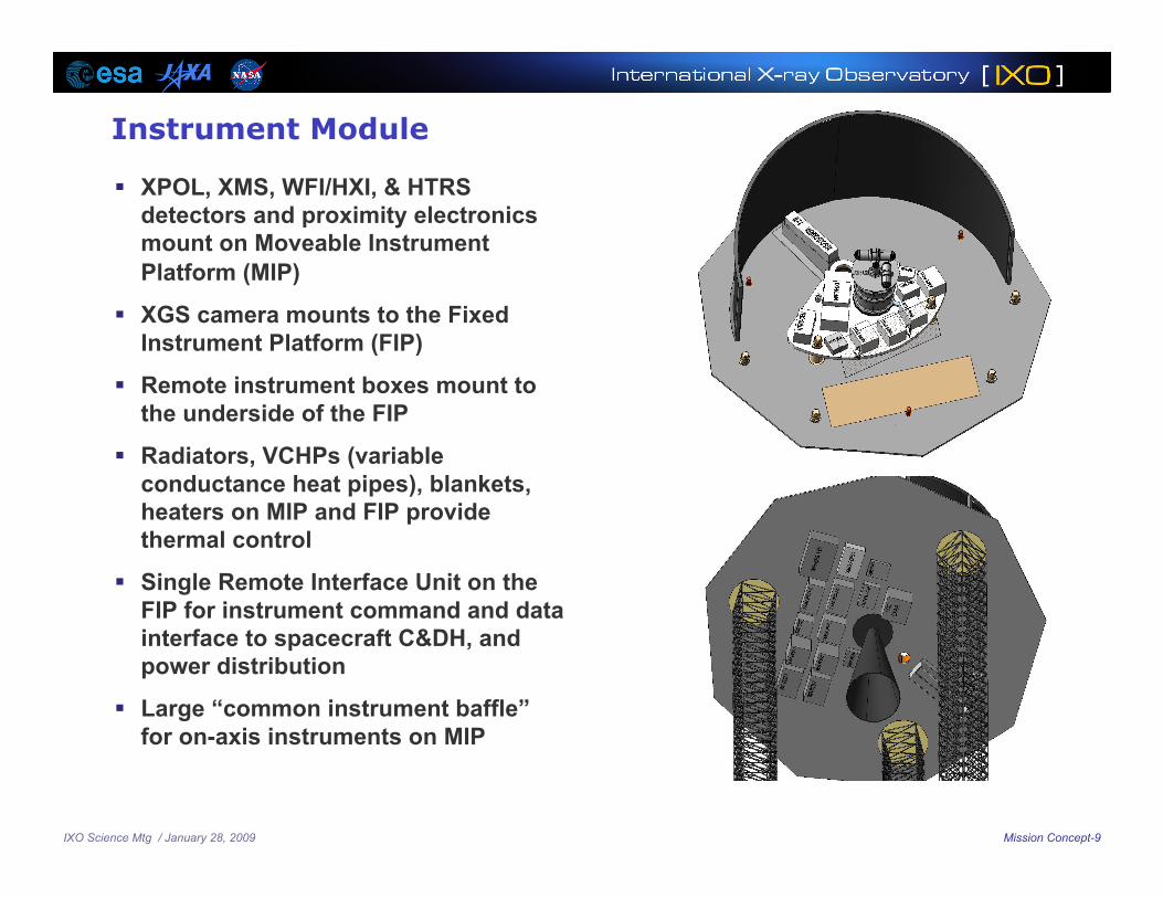
Instrument Module
XPOL, XMS, WFI/HXI, & HTRS detectors and proximity electronics mount on Moveable Instrument Platform (MIP)
XGS camera mounts to the Fixed Instrument Platform (FIP)
Remote instrument boxes mount to the underside of the FIP
Radiators, VCHPs (variable conductance heat pipes), blankets, heaters on MIP and FIP provide thermal control
Single Remote Interface Unit on the FIP for instrument command and data interface to spacecraft C&DH, and power distribution
Large “common instrument baffle” for on-axis instruments on MIP
IXO Science Mtg / January 28, 2009 Mission Concept-10
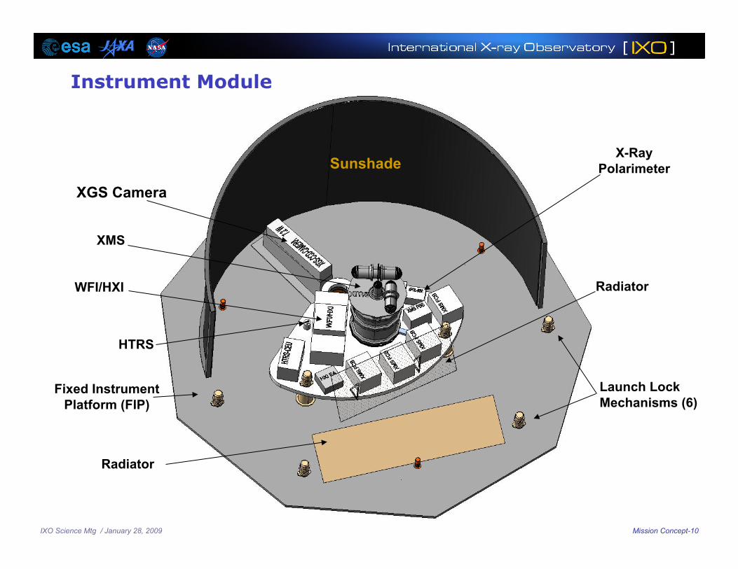
Instrument Module
XGS Camera
Radiator
Fixed Instrument Platform (FIP)
Radiator
Launch Lock Mechanisms (6)
X-Ray Polarimeter
XMS
WFI/HXI
HTRS
Sunshade

IXO Science Mtg / January 28, 2009 Mission Concept-11
XPOL
Instrument Suite Layout
XGS CCD Camera
WFI / HXI
HTRS
XMS (Shown at focus)
Instrument Proximity Electronics (10)
MIP rotation range 133 degrees

IXO Science Mtg / January 28, 2009 Mission Concept-12
Deployment Module 3 ADAM masts deploy the IM,
shroud, baffles and harness – Provides on-orbit alignment
stability between optics and detectors
– First modes: 1.8 Hz bending and 4.1 Hz torsion
– Proven technology – Mast and harness stows into
canister
Shroud blocks light and supports baffles
– Accordion-pleated multi-layer insulation blanket assemblies
– Two concentric blanket assemblies form a “Whipple shield” to minimize micrometeorite penetrations
– Stows in channel on top of the spacecraft bus
10 cm
12.1 m
Shroud stowage channel
ADAM Mast (3)
Concentric MLI blankets In Stowage Channel
Stowed Configuration
Baffle (2) Deployed Configuration
IXO Science Mtg / January 28, 2009 Mission Concept-13
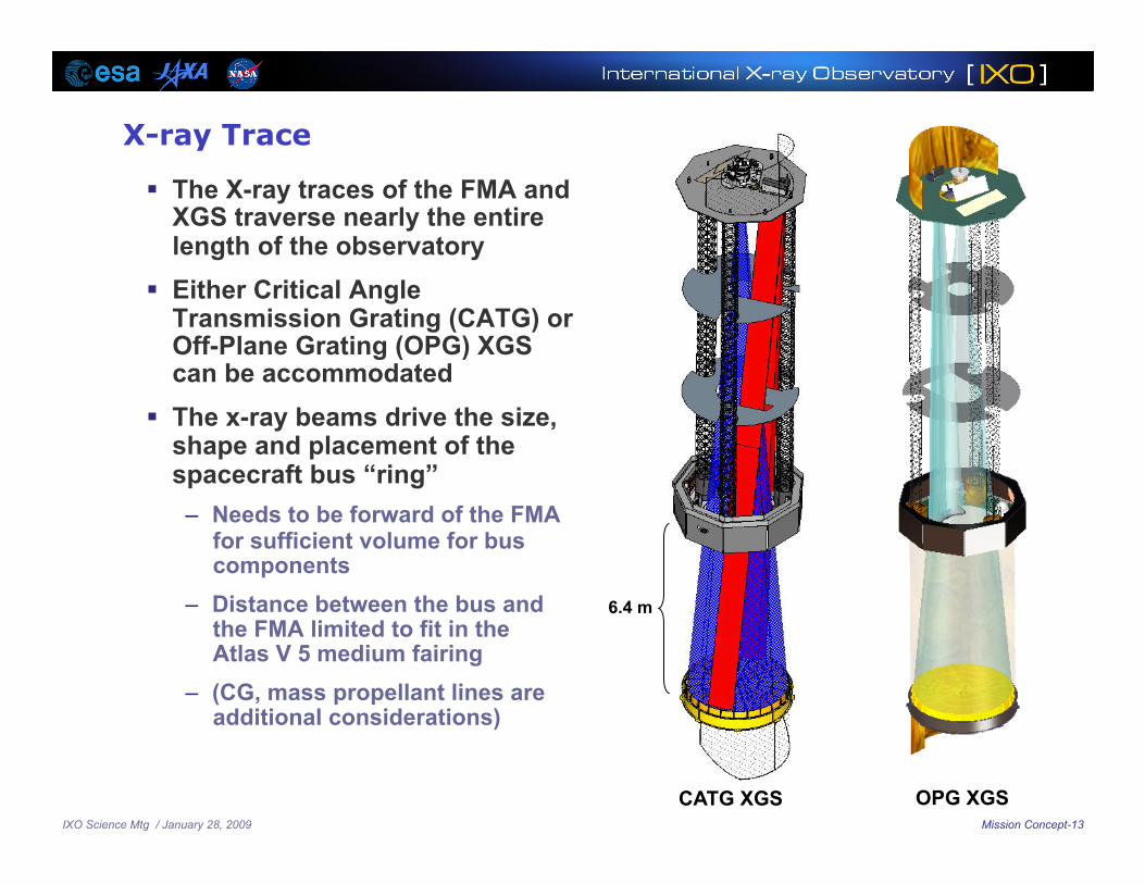
X-ray Trace
The X-ray traces of the FMA and XGS traverse nearly the entire length of the observatory
Either Critical Angle Transmission Grating (CATG) or Off-Plane Grating (OPG) XGS can be accommodated
The x-ray beams drive the size, shape and placement of the spacecraft bus “ring”
– Needs to be forward of the FMA for sufficient volume for bus components
– Distance between the bus and the FMA limited to fit in the Atlas V 5 medium fairing
– (CG, mass propellant lines are additional considerations)
CATG XGS OPG XGS
6.4 m
IXO Science Mtg / January 28, 2009 Mission Concept-14
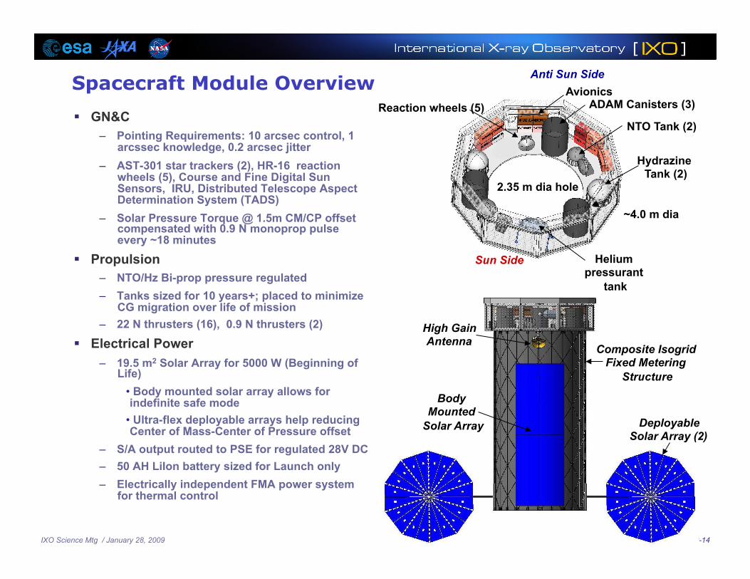
Spacecraft Module Overview
GN&C – Pointing Requirements: 10 arcsec control, 1
arcssec knowledge, 0.2 arcsec jitter – AST-301 star trackers (2), HR-16 reaction
wheels (5), Course and Fine Digital Sun Sensors, IRU, Distributed Telescope Aspect Determination System (TADS)
– Solar Pressure Torque @ 1.5m CM/CP offset compensated with 0.9 N monoprop pulse every ~18 minutes
Propulsion – NTO/Hz Bi-prop pressure regulated – Tanks sized for 10 years+; placed to minimize
CG migration over life of mission – 22 N thrusters (16), 0.9 N thrusters (2)
Electrical Power – 19.5 m2 Solar Array for 5000 W (Beginning of
Life) • Body mounted solar array allows for indefinite safe mode
• Ultra-flex deployable arrays help reducing Center of Mass-Center of Pressure offset
– S/A output routed to PSE for regulated 28V DC – 50 AH LiIon battery sized for Launch only – Electrically independent FMA power system
for thermal control
2.35 m dia hole
ADAM Canisters (3) Reaction wheels (5)
Helium pressurant
tank
Sun Side
Avionics
~4.0 m dia
Anti Sun Side
NTO Tank (2)
Hydrazine Tank (2)
Deployable Solar Array (2)
Body Mounted
Solar Array
Composite Isogrid Fixed Metering
Structure
High Gain Antenna
IXO Science Mtg / January 28, 2009 Mission Concept-15
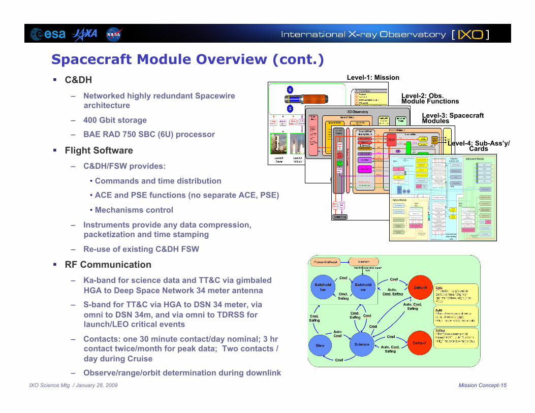
Spacecraft Module Overview (cont.) C&DH
– Networked highly redundant Spacewire architecture
– 400 Gbit storage
– BAE RAD 750 SBC (6U) processor
Flight Software – C&DH/FSW provides:
• Commands and time distribution
• ACE and PSE functions (no separate ACE, PSE)
• Mechanisms control
– Instruments provide any data compression, packetization and time stamping
– Re-use of existing C&DH FSW
RF Communication – Ka-band for science data and TT&C via gimbaled
HGA to Deep Space Network 34 meter antenna
– S-band for TT&C via HGA to DSN 34 meter, via omni to DSN 34m, and via omni to TDRSS for launch/LEO critical events
– Contacts: one 30 minute contact/day nominal; 3 hr contact twice/month for peak data; Two contacts / day during Cruise
– Observe/range/orbit determination during downlink
Level-2: Obs. Module Functions
Level-4: Sub-Ass’y/Cards
Level-1: Mission
Level-3: Spacecraft Modules

IXO Science Mtg / January 28, 2009 Mission Concept-16
NASA FMA Concept
Key requirements: – Effective area /Resolution:
• ~3 m2 @ 1.25 keV; 0.65 m2 @ 6 keV with 5 arcsec angular resolution
• ~150 m2 @30 keV with 30 arcsec ang. res.
Overall dimensions: 3.4 m dia x 0.8 m Segmented Wolter I optical design Slumped glass mirror segments 60 modules: 24 outer, 24 middle, 12 inner 60 mirror modules each with
200-300 segments Hard X-ray mirror module, with multi-layer
coated mirrors, in the center provides high energy response
Total FMA mass is ~1750 kg (current best estimate, no contingency)
Power is ~1400 W to maintain 20 C Finite Element Analyses support design
concept
Thermal Pre-Collimator
Stray Light Baffle
Module
FMA Structure
Spacecraft Interface
Finite Element Model of FMA Structure
IXO Science Mtg / January 28, 2009 Mission Concept-17
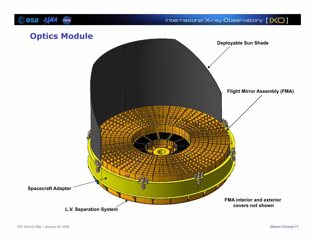
Flight Mirror Assembly (FMA)
FMA interior and exterior covers not shown
Deployable Sun Shade
Spacecraft Adapter
L.V. Separation System
Optics Module

IXO Science Mtg / January 28, 2009 Mission Concept-18
Mechanical
Initial Integrated Modeling Supports Configuration
4.1 Hz Mast Torsion
1.8 Hz Mast Bending
Mechanical
Decenter Requirement < .02 mm
Defocus Requirement < .25 mm
Thermal
Jitter 1.8 Hz
14.1 Hz
IXO Science Mtg / January 28, 2009 Mission Concept-19
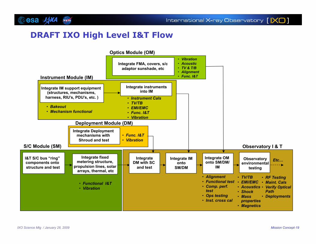
I&T S/C bus “ring” components onto structure and test
Integrate OM onto SM/DM/
IM
Observatory environmental
testing
Integrate IM onto
SM/DM
Integrate fixed metering structure,
propulsion lines, solar arrays, thermal, etc
Integrate DM with SC
and test
Integrate Deployment mechanisms with Shroud and test
Integrate instruments into IM
Integrate FMA, covers, s/c adaptor sunshade, etc
• Vibration • Acoustic • TV & T/B • Alignment • Func. I&T
Integrate IM support equipment (structures, mechanisms,
harness, RIU’s, PDU’s, etc. )
• Bakeout • Mechanism functional
DRAFT IXO High Level I&T Flow
Deployment Module (DM)
• Instrument Cals • TV/TB • EMI/EMC • Func. I&T • Vibration
Instrument Module (IM)
Optics Module (OM)
• TV/TB • EMI/EMC • Acoustics • Shock • Mass
properties • Magnetics
• Alignment • Functional test • Comp. perf.
test • Ops testing • Inst. cross cal
S/C Module (SM) Observatory I & T
Etc…
• RF Testing • Maint. Cals • Verify Optical
Path • Deployments
• Func. I&T • Vibration
• Functional I&T • Vibration

IXO Science Mtg / January 28, 2009 Mission Concept-20
DRAFT Mission Schedule

IXO Science Mtg / January 28, 2009 Mission Concept-21
Next Steps Preparing for Decadal
Finalize observatory system & subsystem updates from MDL: 1/09 – 2/09 – Observatory system & subsystem updates from MDL
Update Payload Definition Document: 1/09 input – 2/09 draft – 3/09 final
Update Technology assessments and plans: 2/09 draft – 3/09 final
Perform Independent Cost and Schedule Estimates: 2/09 – 4/09
Receive Request for Information (RFI) from Decadal: 2/09
Prepare and submit RFI response: 2/09 – 3/09
Receive Request for Programmatic Information from Decadal: 4/09
Prepare/submit Mission Programmatic response to Decadal: 4/09 – 5/09 – Cost and schedules to be reviewed by NASA HQ prior to submittal
Mission presentations to Decadal: 6/09