Embed Size (px)
Citation preview
NASA TECHNICAL
MEMORANDUM NASA TM 83435
I -
Accommodations Assessment: 6 t
(*I I A +O tn n Spaceborne Doppler Lidar .-, .. . F
a0 a 3 , Wii;d Measuring System
By Program Development Preliminary Design Office
August, 1981
NASA
George C. Marshall Space Flight Center Marshall Space Flight Center, Alabama
https://ntrs.nasa.gov/search.jsp?R=19810023201 2018-08-02T13:34:13+00:00Z
ACCOMMODATIONS ASSESSMENT SPACEBORNE DOPPLER LIDAR
WIND MEASURING SYSTEM
CONTENTS
PAGE -
A. BACKGROUND AND SCOPE--------------------------------- 6 B. ASSESSMENT CONCLUSIONS/RECOMMENDATIONS--------------- 7 C. MISSION OBJECTIVES: WIND MEASUREMENT NEEDS----------- 10 D. MISSION TECHNIQUE: PRINCIPLES OF WIND MEASUREMENT---- 1 4
1II.CONFIGURATION AND MASS PROPERTIES------------------------ 24
A, REQUIREMENTS AND ASSUMPTIONS------------------------- 25 8. CONCEPTUAL DESIGN--------------------------L--------- 25 C. S Y S T ~ SIZING---------------------------------------- 27
A. ELECTRICAL POWER------------------------------------- 3 0 B. COMMUNICATIONS AND DATA MANAGEMENT------------------- 35 C. ATTITUDE DETERMINATION AKD CONTROL------------------- 53
V. MISSION OPERATIONS AND PERFORMANCE----------------------- 5 8
A. WIND ACCURACY REQUIREMENT: ORBIT SELECTION----------- 5 9 B. SHUTTLE PERFORMANCE: DESIGN AND OPERATIONAL
IM~LICATIONS----------------------------------------- 63
KEY CONTilIBUTORS (CONTRIBUTOR, OFFICE SYMWL, DISCIPLINE
The assessment activities summarized here were performed by the below-named members of the MSFC Preliminary Design Off ice (PDO1). However, it is appropriate to acknowledge the assistance of Mr. J. Bilbro (EC32) relative to the characteristics and principles of doppler lidar wind measuring systems. Also, Mr. R. Beranek (PS06) provided guidance to the over-all assessment of which these PDOl activities were a part.
J. STEINCAMP, PD34, ENGINEERING STUDY MANAGER
J. HOWELL, PD12, SUBSYSTEMS LEAD ENGINEER/ATTITUDE DETERMINATION AND CONTROL
W. FINNELL, PD14, COMMUNICATIONS 61 DATA MANAGEMENT
W. JOHANSON, PD24, MASS PROPERTIES
D. MERCIER, PD33, STS PERFORMANCE
J. PEOPLES, PD22, THERMAL ANALYSIS
R. ROOD, PD14, ELECTRIC9L POWER
T. WHEELGR, PD32, ATMOSPHERIC ENVIRONMENT
A. YOUNG, PD32, FLIGHT PERF3RYANCE
D. WALTON, PD32, DOCUMENTA'FION
LIST OF FIGURES
I .A-1
1.B-1
I. D-1
1I.A-1
1I.B-1
1I.B-2
1II.A-1
1V.A-1
IV. A-2
1V.A-3
IV. A-4
1V.A-5
1V.A-6
1V.A-7
IV. A-8
IV. B-1
1V.B-2
Doppler Lidar Wind Measuring System
Programmatic Schedule
Lidar System Concept (Laser 6 Optical Subsystems)
SNR vs . Altitude Molecular Absorption Coefficient
IR Backscattering Coefficient as a Function of Altitude
Launch Configuration
EPS Block Diagram
Solar Array Block Diagram
Suntime Fraction (Sun-Synchronous Orbit)
Suntime Fraction
EPS Efficiency Block Diagram
Solar Array Cross Section
Solar Array Sizing
LIDAR EPS Summary
LIDAR Pulse Temporal and Spectral Characteristics
TDRSS Coverage Geometry
IV. B-3 TDRSS Dead Zone
1V.B-4 Tape Recorder Design Life
1V.B-5 CDMS Block Diagram
1V.B-6 CDMS Summary
1V.C-1 Spacecraft Coordinate System
1V.C-2 Local Vertical Misalignment Geometry
1V.C-3 ACDS Block Diagram
1V.C-4 ACDS Summary
3
, C ' s l - - L *-,. - - --.

LIST OF FIGURES (CONTINUED)
V.A-1 Wind Accuracy Variation with SNR
V.A-2 Wind Accuracy Sensitivity to Signal-to-Noise Ratio
V.A-3 Comparison of Orbital Altitudes and Inclinations
V. B-1 Shuttle Performance (VAFB Launch)
V.B-2 Augmented Shuttle Performance (VAFB, Unofficial)
V.B-3 Shu1:tle Performance (KSC, Unofficial 1

I. INTRODUCTION
I. INTRODUCTION
I.A. BACKGROUND AND SCOPE
This dccument summarizes the activities carried out by the MSFC Preliminary Design Office as part of the NASA assessment of a spaceborne doppler lidar wind measuring sys-
, tem concept. The assessment was requested by Dr. Ron Greenwood, Director of the Environmental Observation Division, Office of Space and Terrestrial Applications, of NASA Headquarters, who designated MSFC as the lead center, to be supported by JPL, LaRC, and GSFC in selected disciplines augmenting MSFC's experience in ground and airborne pulsed C02 doppler lidar wind measuring systems.
The assessment activity was organized to concentrate on three areas vital to concept feasibility:
o Laser and optical systems (Lidar S Y S C ~ hardware
o Atmospheric characteristics
o Spacecraft Accommodations
with corresponding assignments of responsibilities to the MSFC Optical and RF Systems Division, Atmospheric Sciences Division, and Preliminary Design Office. Overall assessment coordination was provided by the MSFC Advanced Studies Office.
The system concept under consideration was defined in three reports:
1) "Feasibility Study of Satellite - Borne Lidar Global Wind Monitoring System", NOAA Tech. Memo ERL WPL-37 (1978)
2 ) "Feasibility Study of Satellite - Borne Lidar Global Wind Monitoring System, Part II", NOAA Tech. Memo ERL WPL-63 ( 1980)
3 ) NOAA LMSC WINDSAT Study, Final Briefing Charts (Sep 1980) Contract NA 79 RAC 00127
The L&c study was managed by the NOAA ~nvironmental Resources Laboratory and funded by the USAF Space Division. All three studies emphasized a Shuttle-borne system, which was considered an evolutionary step in the development of an operational system.
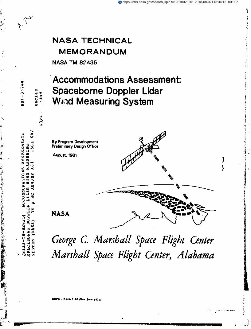
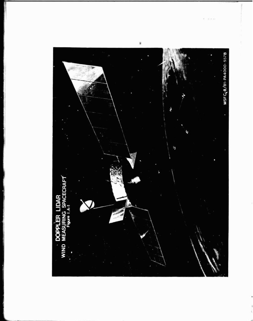
A "clean sheet" approach to spacecraft concep- tual design was taken to provide the greatest flexibility in accommodating the mission equipment requirements. This seemed particularly appropriate in view of the electrical power requirements, which would require significant modifica- tion of existing spacecraft. Figure 1.A-1 is an artist's concept of the operational system.
I.B. ACCOMMODATIONS ASSESSMENT CONCLUSIONS/ RECOMMENDATIONS
Subject to the three caveats following, the principal conclusion of this assessment is that a spacecraft with the capabilities needed to support the operation of the doppler lidar wind measuring system is technically feasible. Cost estimates prepared for a dedicated, new-development spacecraft (using standard, available, and/or existing tech- nology components) suggest economic feasibility of such a spacecraft. Such a new development may be unnecessary: the present assessment did not include detailed consideration of the potential use of existing and "in-development" spacecraft and platforms. The caveats are that
1) cryogenic cooling of the photodetector will not be required in the operational system,
2 ) detailed structural/pointing analyses will es- tablish feasibility of short-terra optical axis stability for efficient lidar heterodyning, and
3 laser power requirements will not increase beyond those now anticipated by more than a factor of three.
The structural and pointing specialists consulted were of the opinion that an acceptable short-term stability could be realized, but that proof of their opinion would require analyses beyond the scope of the assessment. The laser power requirements are a critical design driver: the spacecraft conceptualized in this assessment will not be adequate if the laser power requirement increases much beyond the assumed range of 2140-2340 W. Since the laser power requirement ir most particularly determined by atmospheric backscatter, better 'knowledge of this parameter is required to adequately scope the spacecraft definition activity.
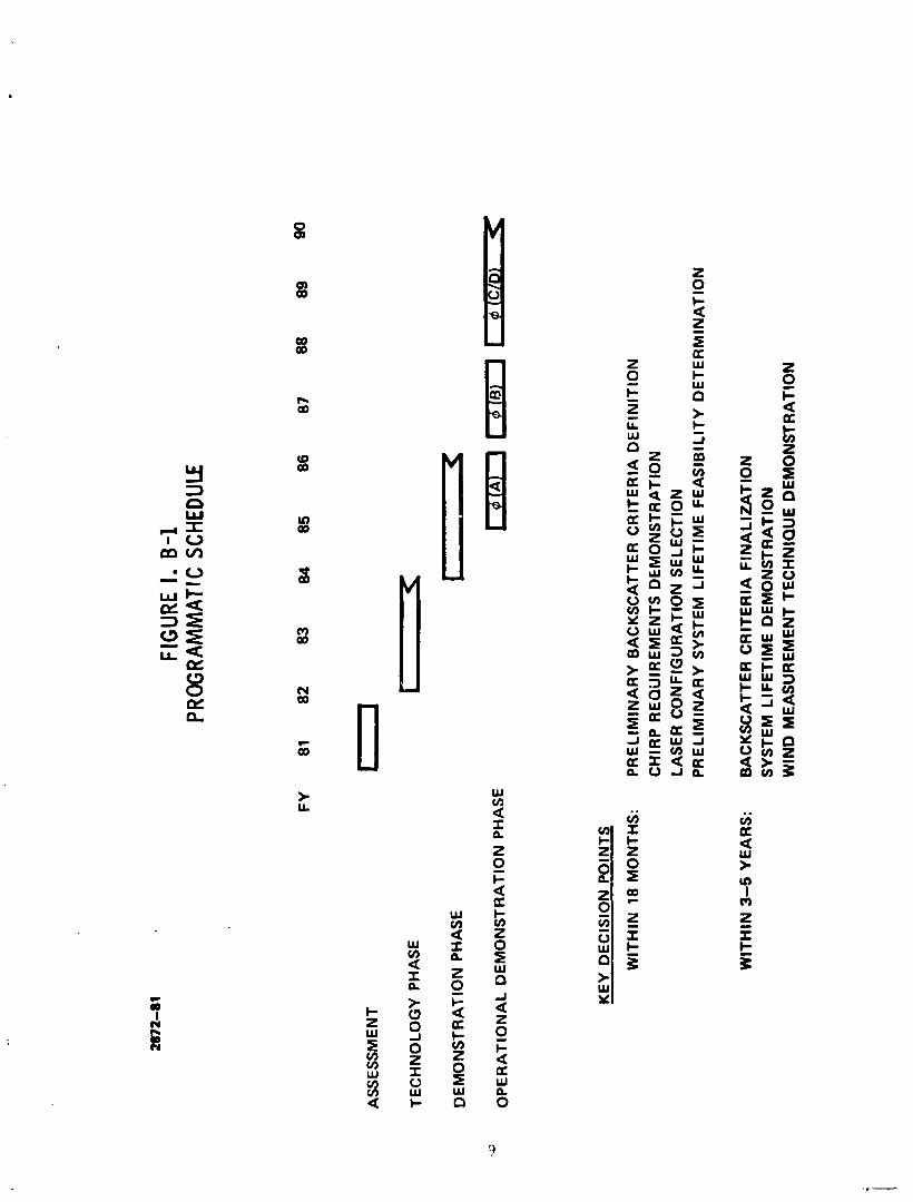
The uncertainty relative to atmospheric back- scatter, together with the need for demonstration of adequate laser lifetime and chirp (intra-pulse frequency stability) characteristics, were key considerations in the formulation of the schedule recommendation shown in Figure 1.B-1. In
FIG
URE I. 0
-1
PRO
GRA
MM
ATIC
SCH
EDUL
E
AS
SE
SS
ME
NT
TE
CH
NO
LO
GY
PH
AS
E
DE
MO
NS
TR
AT
ION
PH
AS
E
.U
OP
ER
AT
ION
AL
DE
MO
NS
TR
AT
ION
PH
AS
E
KE
Y D
EC
ISIO
N P
OIN
TS
WIT
HIN
18
MO
NT
HS
: P
RE
LIM
INA
RY
BA
CK
SC
ATT
ER
CR
ITE
RIA
DE
FIN
ITIO
N
CH
IRP
RE
QU
IRE
ME
NT
S D
EM
ON
ST
RA
TIO
N
LAS
ER
CO
NF
IGU
RA
TIO
N S
EL
EC
TIO
N
PR
EL
IMIN
AR
Y S
YS
TE
M L
IFE
TIM
E F
EA
SIB
ILIT
Y D
ET
ER
MIN
AT
ION
WIT
HIN
3-5
Y
EA
RS
: B
AC
KS
CA
TTE
R C
RIT
ER
IA F
INA
LIZ
AT
ION
S
YS
TEM
LIF
ET
IME
DE
MO
NS
TR
AT
ION
W
IND
ME
AS
UR
EM
EN
T T
EC
HN
IQU
E D
EM
ON
ST
RA
TIO
N
particular, a phased hardware development program should be initiated after technology studies yield adequate definition of system requirements.
System studies should continue at an appropriate level to provide guidance to the technology studies and to evolve system requirements. The needs for ground truthfng and observations of localized meterological phenomena should be defined as early as possible, as these needs may become 3 .sign drivers.
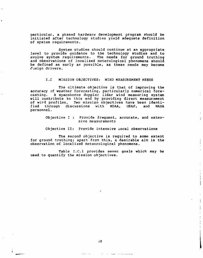
1.C MISSION OBJECTIVES: WIND MEASUREMENT NEEDS
The ultimate objective is that of improving the accuracy of weather forecasting, particularly numerical fore- casting. A spaceborne doppler lidar wind measuring system will contribute to this end by providing direct measurement of w i ~ d profiles. Two mission objectives have been identi- fied through discussions with NOAA, USAF, and NASA personnel.
Objective I : Provide frequent, accurate, and exten- sive measurements
Objective 11: Provide intensive local observations
The second objective is required to some extent for ground truthing; apart from this, a desirable aim is the observation of localized meteorological phenomena.
Table I.C.l provides seven goals which may be used to quantify the mission objectives.
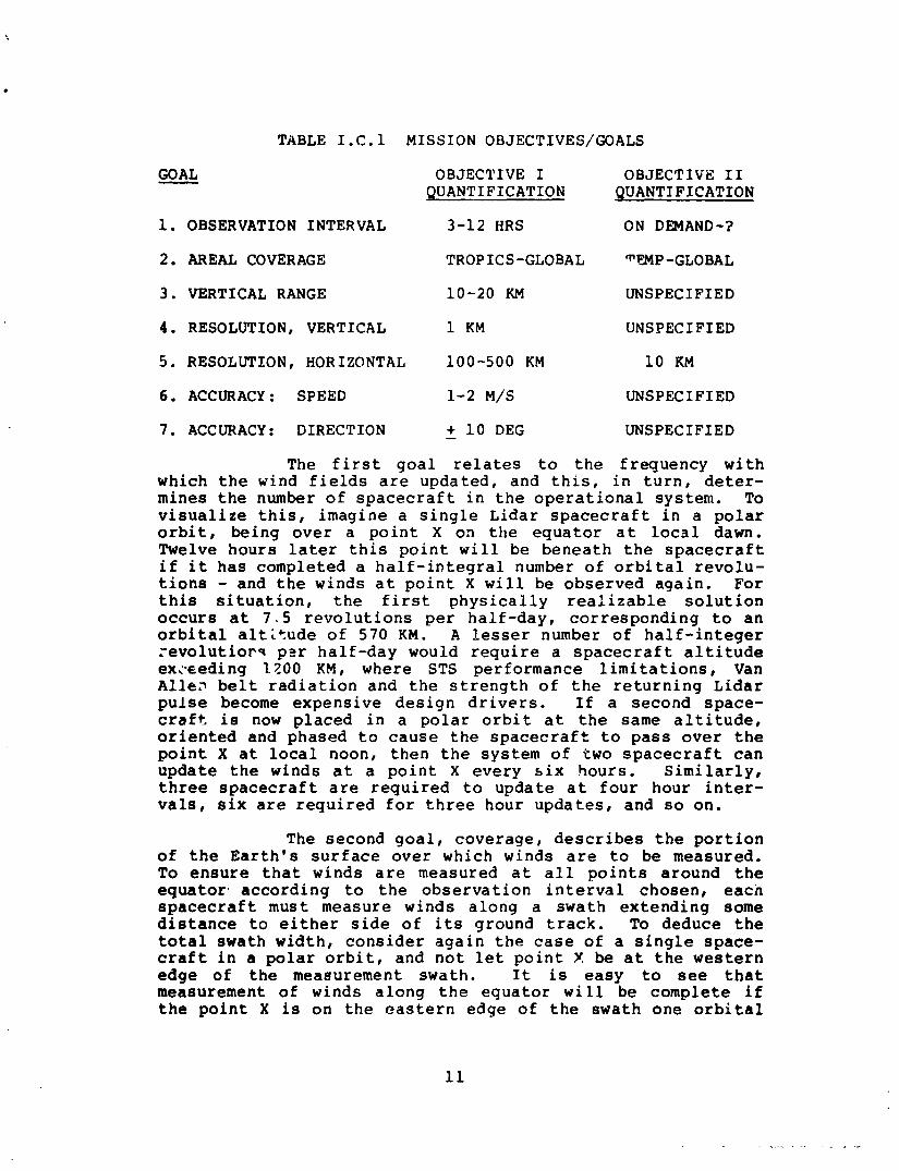
TABLE I . C . l MISSION OBJECTIVES/GOALS
GOAL - OBJECTIVE I OBJECTIVE 11 QUANTIFICATION QUANTIFICATION
1. OBSERVATION INTERVAL 3-12 HRS ON DEMAND-?
2. AREAL COVERAGE TROPICS-GLOBAL -GLOBAL
3. VERTICAL RANGE 10-20 KM UNSPECIFIED
4 . RESOLUTION, VERTICAL 1 KM UNSPECIFIED
5. RESOLUTION, HORIZONTAL 100-500 KM 1 0 KM
6. ACCURACY : SPEED 1-2 M/S UNSPECIFIED
7. ACCURACY : DIRECTION - + 1 0 DEG UNSPECIFIED
The f i r s t g o a l relates t o t h e f r e q u e n c y w i t h w h i c h t h e wind f i e l d s a re u p d a t e d , a n d t h i s , i n t u r n , d e t e r - m i n e s t h e number o f s p a c e c r a f t i n t h e o p e r a t i o n a l s y s t e m . To v i s u a l i z e t h i s , i m a g i n e a s i n g l e Lidar s p a c e c r a f t i n a p o l a r o r b i t , b e i n g o v e r a p o i n t X o n t h e e q u a t o r a t l o c a l dawn. Twelve h o u r s l a te r t h i s p o i n t w i l l be b e n e a t h t h e s p a c e c r a f t i f i t h a s c o m p l e t e d a h a l f - i n t e g r a l number o f o r b i t a l r e v o l u - t i o n s - a n d t h e w i n d s a t p o i n t X w i l l b e o b s e r v e d a g a i n . F o r t h i s s i t u a t i o n , t h e f i r s t p h y s i c a l l y r e a l i z a b l e s o l u t i o n o c c u r s a t 7 . 5 r e v o l u t i o n s per h a l f - d a y , c o r r e s p o n d i n g t o a n o r b i t a l a l t i t u d e o f 570 K M . A lesser number o f h a l f - i n t e g e r . - e v o l u t i o r s p z r h a l f - d a y would r e q u i r e a s p a c e c r a f t a l t i t u d e ex,-eeding 1200 K M , w h e r e STS p e r f o r m a n c e l i m i t a t i o n s , Van A l l e ~ b e l t r a d i a t i o n a n d t h e s t r e n g t h o f t h e r e t u r n i n g L i d a r p u l s e become e x p e n s i v e d e s i g n d r i v e r s . I f a s e c o n d s p a c e - c r a f t i s now p l a c e d i n a p o l a r o r b i t a t t h e same a l t i t u d e , o r i e n t e d a n d p h a s e d t o c a u s e t h e s p a c e c r a f t t o p a s s o v e r t h e p o i n t X a t local noon , t h e n t h e s y s t e m o f t w o s p a c e c r a f t c a n u p d a t e t h e w i n d s a t a p o i n t X e v e r y s i x h o u r s . S i m i l a r l y , t h r e e s p a c e c r a f t a re r e q u i r e d t o u p d a t e a t f o u r h o u r i n t e r - v a l s , s i x are r e q u i r e d f o r t h r e e h o u r u p d a t e s , a n d so o n .
The s e c o n d g o a l , c o v e r a g e , d e s c r i b e s t h e p o r t i o n of t h e E a r t h ' s s u r f a c e o v e r wh ich w i n d s are t o be m e a s u r e d . To e n s u r e t h a t w i n d s a r e m e a s u r e d a t a l l p o i n t s a r o u n d t h e e q u a t o r - a c c o r d i n g t o t h e o b s e r v a t i o n i n t e r v a l c h o s e n , e a c n s p a c e c r a f t m u s t m e a s u r e w i n d s a l o n g a s w a t h e x t e n d i n g some d i s t a n c e t o e i t h e r s i d e o f i t s g r o u n d t r a c k . To d e d u c e t h e t o t a l s w a t h w i d t h , c o n s i d e r a g a i n t h e case o f a s i n g l e s p a c e - c r a f t i n a p o l a r o r b i t , a n d n o t l e t p o i n t X be a t t h e w e s t e r n e d g e o f t h e measu remen t s w a t h . I t is e a s y t o see t h a t measu remen t o f w i n d s a l o n g t h e e q u a t o r w i l l b e complete i f t h e p o i n t X is o n t h e e a s t e r n e d g e o f t h e s w a t h o n e o r b i t a l
p e r i o d l a t e r . Us ing t h e o r b i t a l p e r i o d a l r e a d y c a l c u l a t e d , t h e total . s w a t h w i d t h is r e a d i l y shown t o b - a b o u t 2700 KM. Note t h a t t h i s v a l u e r e s u l t s f rom a s s u m i n g t h a t t h e r e are n o measurement g a p s a l o n g t h e e q u a t o r , a n d so is i n d e p e n d e n t o f t h e o b s e r v a t i o n i n t e r v a l . F u r t h e r n o t e t h a t , a l t h o u g h w i n d s a l o n g t h e e q u a t o r are m e a s u r e d e x a c t l y o n c e d u r i n g t h e o b s e r - v a t i o n i n t e r v a l , w i n d s i n t h e temperate a n d a r t i c r e g i o n s are m e a s u r e d more f r e q u e n t l y d u e t o t h e o v e r l a p p i n g measu remen t s w a t h s i n t h e s e z o n e s . I n t h i s c o n n e c t i o n , t h e r e is a cir- c u m s t a n c e wh ich may be e x p e c t e d t o f i g u r e i n a n y f u t u r e d o p p l e r l i d a r wind measu remen t s y s t e m t r a d e s t u d i e s : t r o p i - cal w i n d s c a n n o t b e d e d u c e d r e l i a b l y f rom t e m p e r a t u r e a n d p r e s s u r e measu remen t s owing t o t h e s m '-1 g r a d i e n t s o f t h e s e p a r a m e t e r s i n t h e t r o p i c s . E l s e w h e r e , d i r e c t w i n d m e a s u r e - m e n t s c a n improve o n p r e s e n t m e t h o d s . I n t h e p o l a r z o n e s , a b o v e a f e w k i l o m e t e r s , t h e s i g n a l - t o - n o i s e r a t i o (SNR) o f t h e r e t u r n i n g l i d a r p u l s e i s less t h a n a t o t h e r l a t i t u d e s , w h i c h t e n d s t o r e d u c e t h e a t t a i n a b l e a c c u r a c y . However, t h e o v e r l a p p i n g s w a t h s j u s t described p r o v i d e more m e a s u r e m e n t s , a n d t h i s s l i g h t l y o f f s e t s t h e a c c u r a c y r e d a ~ c t i o n .
The t h i r d a n d f o u r t h g o a l s , v e r t i c a l r a n g e a n d r e s o l u t i o n , re la te t o t h e a l t i t u d e s t o w h i c h , a n d v e r t i c a l s p a c i r l g s a t w h i c h , w i n d s c a n b e m e a s u r e d . A 1 KM ve r t i c a l r e s o l u t i o n means t h a t t h e a v e r a g e h o r i z o n t a l wind i a t o b e e s t i m a t e d i n e a c h 1 KM "sLabl', up t o t h e v e r t i c a l r a n g e . The v e r t i c a l r e s o l u t i o n i s l i m i t e d by t h e l i d a r p u l s e l e n g t h , t h e " least r e a s o n a b l y c o n c e i v e a b l e v a l u e " b e i n g a b o u t 400 KM ( t h i s d o e s n o t s u g g e s t t h a t so f i n e a v e r t i c a l r e s o l u t i o r i is e c o n o m i c a l l y a t t a i n a b l e , or e v e n m e t e o r o l o g i c a l l y u s e f u l ) . The s t r e n g t h o f t h e r e t u r n i p 3 l i d a r p u l s e d e p e n d s o n t h e b a c k s c a t t e r f rom a t m o s p h e r i c a e r o s o l s - w h o s e c o n c e n t r a t i o n must. u l t i m a t e l y d e c r e a s e w i t h a l t i t u d e a n d v a r y w i t h g e o - g r a p h i c l o c a t i o n , s e a s o n , t i m e o f d a y , and o c c u r r e n c e o f a e r o s o l - p r o d u c i n g e v e n t s ( e . g . , d u s t storms a n d v o l c a n i c a c t i v i t y ) . T h i s i m p l i e s t ! i a t t h e maximum a l t i t u d e fron! w h i c h u s e f u l r e t t r n s w i l l be o b t a i n e d w i l l v a r y w i t h a l l t h e s e f a c t o r s . Thus , t h e lower f i g u r e o f 1 0 KM g i v e n f o r t h e v e r t i c a l r a n g e s h o u l d b e t a k e n a s i n d i c a t i v e o f a n e e d f o r measu remen t o f w i n d s u p t o t h e t r o p o p a u s e (whose h e i g h t v a r i e s w i t h s e a s o n a n d l a t i t u d e ) , w h i l e t h e u p p e r f i g u r e s u g g e s t s t h e u t i l i t y o f s t r a t o s p h e r i c wind m e a s u r e m e n t s .
The fifth goal, horizu~tal resolution, derives from two circumstances. First, present numerical weathsr models operate with qeographic grids in which the mean wind over the grid (in each vertical resolution element) is used. Second, only the radial component of wind along the lidar pointing direction can be measured from each pulse (again, in each vertical resolution element). Thus, it is necessary to direct several lidar pulses at a given qeographical area, from different directions, to estimate the mean wind by vector resolution. The area, or grid, is usually taken t,o be square, and the horizontal resolution is the length of the grid side. The lower figure of 100 KM would be representa- tive of small area (fine mesh) modeling. The upper figure of 500 KM would be associated with hemispheric or global model- inq. This discussion implies that the flow of data from a doppler lidar wind-measuring spacecraft is not well matched to conventional large-area numerical forecasting models whose world- view requires regular grids and synoptic measurements. This mis-match poses no insurmountable mathematical or physi- cal problem, but does indicate the need for model "velop- ments to effzctively exploit the wind data. The relationship of the data produced and the using models should be factored into future systems engineering studies.
The sixth and seventh goals, accuracies, de- scribe the accuracy with which mean grid winds are to be measured. The values given are slightly more stringent than the accuracies attained when winds are calculated from tem- perature and pressure measurements.
As noted at the start of this Section', a space- born2 doppler lidar is expected to improve numerical weather forecasting by providing direct wind measurements on a global scale. It seems likely that the flow of data from such a system, with some additional ground and/or onboard process- ing, would permit inference of other atmospheric dynamic parameters (e.g., cloud cover characteristics). The informa- tion so gained would not only enhance the contribution to forecasting, but also serve to advance understanding of atmospheric processes. This assessment has focused on the practicability of, and requirements for, accommodating a lidar system on a free-f lyinq operational spacecraft, with some limited consideration of other accommodations posoibili- ties. Not addressed was the possibility of accommodating additional meteorological sensors which, operated in conjunc- tion with a doppler lidar, would provide an even greater contribution to the ultimate objective and, possibly, under- standing of atmospheric processes. Both possibilities-fuller exploitation of doppler lidar data and complementary sensors - should be considered in future studies.
Certain simplifying assumptions were made above to illustrate the concepts of fleet sizing and swath widths. The precise assumptions (e.g., polar orbits) and parameters based thereon (e.g., 570 KM orbital altitude) are not neces- sarily required in practice. The conclusions about the required fleet size remain valid.
I.D. MISSION TECHNIQUE: PRINCIPLES OF WIND MEASUREMENT - The word "lidarn was originally an acronym for
"Light Detection and Ranging" - i.e., a lidar is a radar operating at optical frequencies. In the system under con- sideration, a pulse of light of a few microseconds duration, at an essentially constant frequency, is directed at a geographically-fixed volume of the atmosphere. Particles (aerosols) in the volume reflect (backscatter) a portion of the pulse energy back along the direction of propagation of the pulse. This energy is collected at the system and its frequency compared to the frequency of the emitted pulse by optical heterodyning. The relative velocity between the system and the aerosols (or, more precisely, the relative velocity component along the direction of propagation) is defined by the frequency difference, caused by the doppler effect.
The motion of the Earth in inertial space is calculable, and the motion of the spaceborne lidar system can be determined by use of the global positioning system ( G P S ) . The attitude of the spacecraft will be maintained by the onboard inertial reference subsystem. With this ixformation and knowledge of the beam pointing direction, the doppler frequency shift due to spacecraf t-Earth motion can be factored out of the total shift, with a remainder due only to the component of aerosol motion along the beam pointing direction. If the aerosols are assumed to move with the wind, then the component of wind motion along the beam point- ing direction has been determined. If the wind field ic the atrnospberic volume is uniform, then directing several pulses into the volume from different points on the orbit permits determination of the wind components by vector resoluti~n along the different beam pointing directions. Although the assumption of wind field uniformit;? over the atmospheric volume does not always hold, particularly when the volume corresponds to the larger horizontal resoluticn elements, the nonuniformity does not compromise the concept, as only the mean wind in the volume is sought. In the usual case, it may also be assumed that vertical winds are negligible: the ex- ceptions are generally localized and/or transient phenomena.
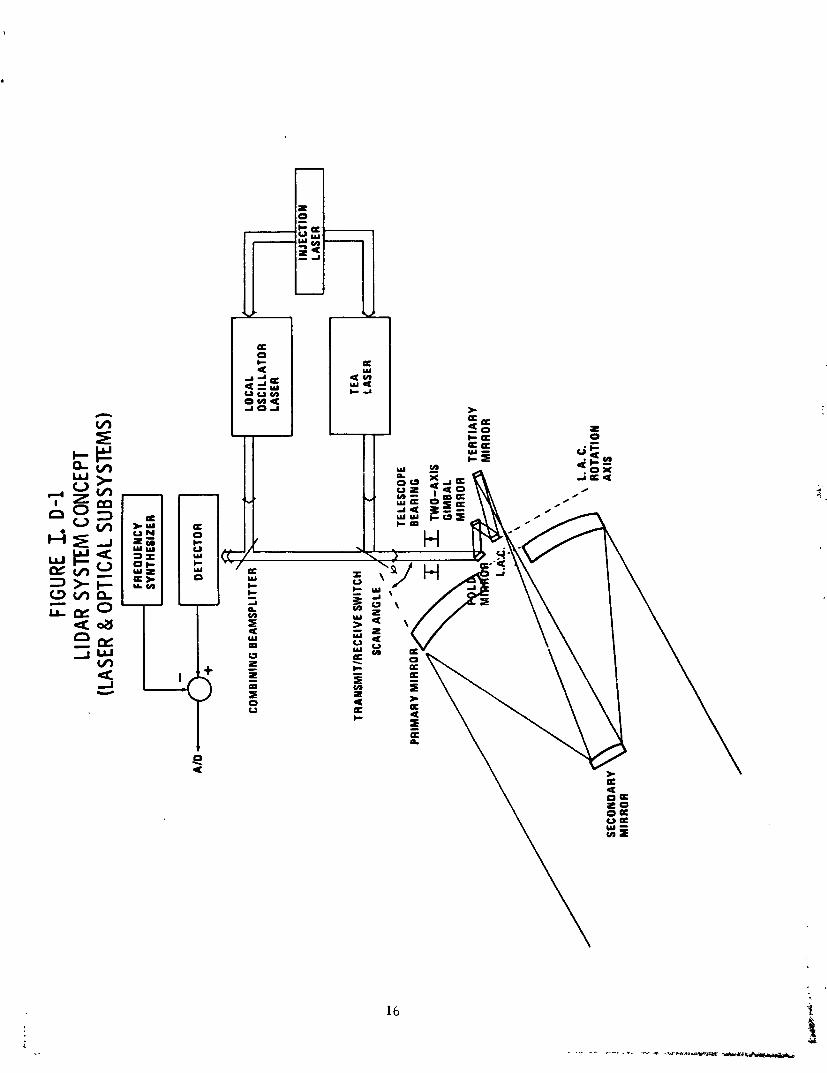
Figure I.D.1, adapted from the NOAA/LMSC WINDSAT final briefing package, illustrates a doppler lidar wind- measuring system concept. The primary "TEA" (Transversely Excited, Atmospheric)laser output pulses are reflected by an optomechanical switch in the "transmit" positon through a beam alignment subsystem consisting of a fold mirror, a two- axis gimbaled mirror, and a LAC (Lag Angle Compensating) mirror. The pulse is then reflected from the tertiary mirror into the cassegrainian telescope, which expands the beam and directs it at the atmosphere. The pointing direction in this concept is controlled by rotating the telescope about the local vertical at an offset scan angle. In principle, this rotation can be either ctntinuous or stepped.
The returning pulse of backscattered light is collected by the cassegrainian telescope and reflected by the tertiary mirror through the beam alignment subsystem, which directs it through the "receive" position of the switch. The beam alignment subsystem corrects the misalignment due to Bradley abberation caused by the spacecraft motion and, if the rotation is continuous, for the rotation of the telescope (lag angle) during the pulse roundtrip time (typically be- tween 5 and 10 milliseconds). After passing through the switch, the returning light is mixed with a frequency- offset beam from a local oscillator laser by a combining beamsplitter. The offset permits the sense of the doppler shift (red or blue) to be determined. The frequencies of both the local oscillator and the TEA laser are controlled by the technique of injection locking.
The mixed light from the combining beam-splitter forms an interference pattern on the photo-detector. This pattern varies with the doppler-shifted frequency of the re- turning light. Thus, the detector output is an FM-modulated electrical sign31 whose modulation frequency corresponds to the doppler shift. The predictable shift due to the spacecraft-Earth moti-n will vary by about +1.7 GHz, depend- ing on whether the beam pointing directron is along or against the spacecraft velocity vector. The function of the frequency synthesizer in the removal of this "grossn doppler shift. The result.ing signal is then digitized and range- gated (corresponding to the vertical resolution elements) and, after further preprocessing to extract signal character- istics, recorded for later downlinking.
FIGU
RE I. D
-1
LIDA
R SY
STEM
CON
CEPT
(L
ASER
& O
PTIC
AL S
UBSY
STEM
S)
11. SYSTEM PERFORMANCE ANALYSIS
I1 .A. SIGNAL-TO-NOISE RATIO
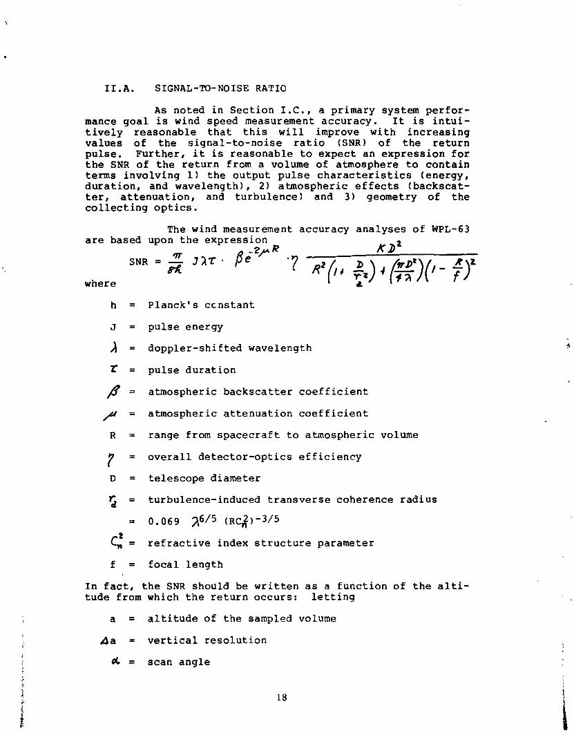
As noted in Section I.C., a primary system perfor- mance goal is wind speed measurement accuracy. It is intui- tively reasonable that this will improve with increasing values of the signal-to-noise ratio (SNR) of the return pulse. Further, it is reasonable to expect an expression for the SNR of the return from a volume of atmosphere to contain terms involving 1) the output pulse characteristics (energy, duration, and wavelength), 2 ) atmospheric effects (backscat- ter, attenuation, and turbulence) and 3 ) geometry of the collecting optics.
The wind measurement accuracy analyses of WPL-63 are based upon the expression
J7T - 2 + R KD*
SNR = - 315. pe 8%
where
h = Planck's ccnstant
J = pulse energy
= doppler-shifted wavelength
Z = pulse duration
f l = atmospheric backscatter coefficient
,& = atmospheric attenuation coefficient
R = range from spacecraft to atmospheric volume
7 = overall detector-optics efficiency
D = telescope diameter
5 = turbulence-induced transverse coherence radius
= 0.069 2615 (~~:)-3/5
C: = refractive index structure parameter
f = focal length
In fact, the SNR should be written as a function of the alti- tude from which the return occurs: letting
a = altitude of the sampled volume
A a = vertical resolution
d = scan angle
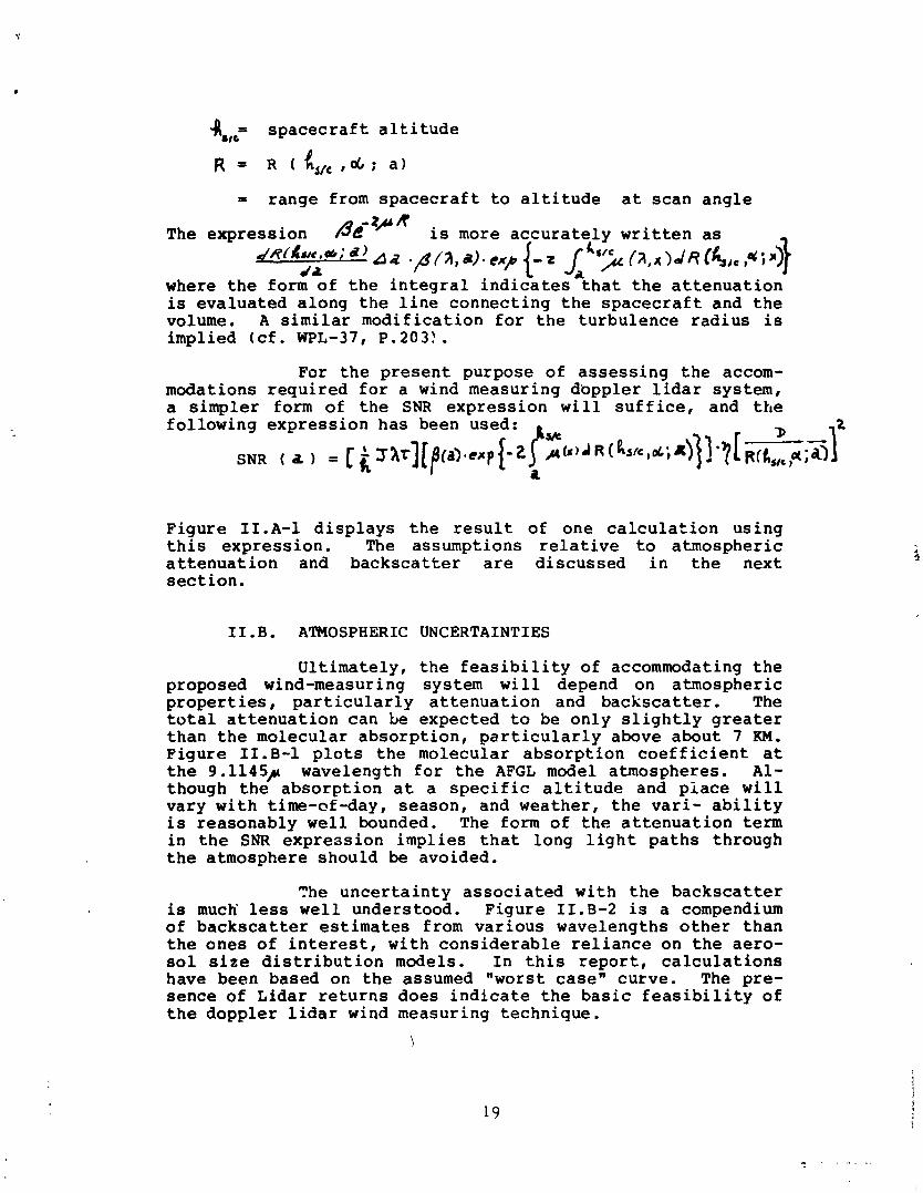
4 , spacecraft altitude
= range from spacecraft to altitude at scan angle
The expression fie-4UR is more accurately written as ~ R ( R N C . & ; a)
da 11 . B ~ ~ , a ) O l r {-z J,'s> ( l , l ~ d ~ ( t i , ~ ,Q+#
where the form of the integral indicates that the attenuation is evaluated along the line connecting the spacecraft and the volume. A similar modification for the turbulence radius is implied (cf. WPL-37, P.203!.
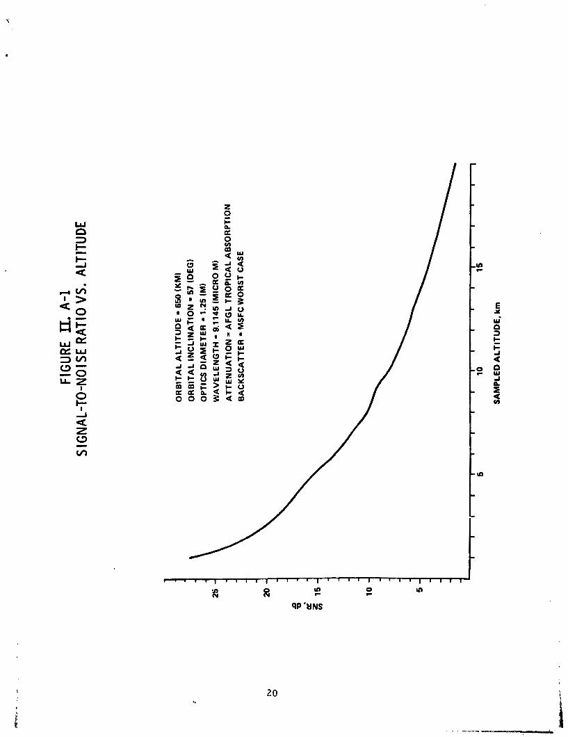
For the present purpose of assessing the accom- modations required for a wind measuring doppler lidar system, a simpler form of the SNR expression will suffice, and the following expression has been used: k*
- , I s ~ r l [ g ~ a . ~ ~ { - z J , 4 4 ( ~ ) ~ ~ ( ~ 5 ~ . ~ ; 4 ] ! * ? [ .aU,M;o S N R ( 2 ) - a
Figure 1I.A-1 displays the result of one calculation using this expression. The assumptions relative to atmospheric attenuation and backscatter are discussed in the next section.
I I. B. ATMOSPHERIC UNCERTAINTIES
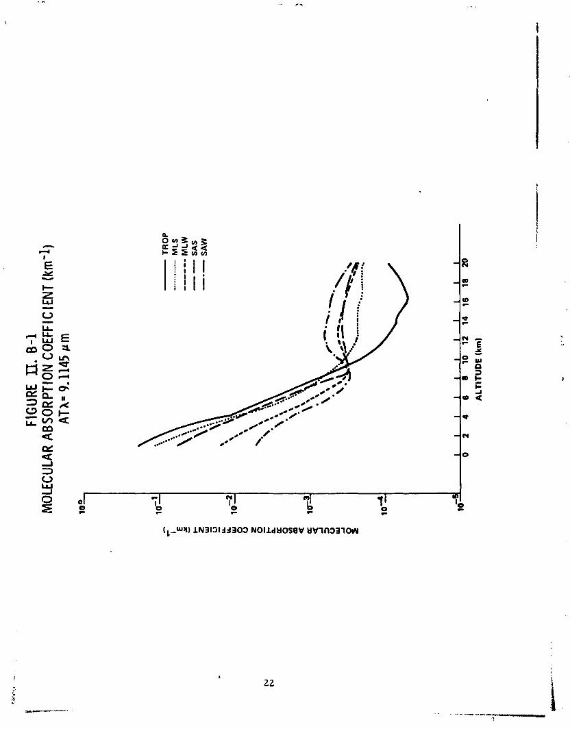
Ultimately, the feasibility of accommodating the proposed wind-measuring system will depend on atmospheric properties, particularly attenuation and backscatter. The total attenuation can be expected to be only slightly greater than the molecular absorption, particularly above about 7 KM. Figure 1I.B-1 plots the molecular absorption coefficient at the 9.1145,~ wavelength for the AFGL model atmospheres. Al- though the absorption at a specific altitude and place will vary with time-of-day, season, and weather, the vari- ability is reasonably well bounded. The form of the attenuation term in the SNR expression implies that long light paths through the atmosphere should be avoided.
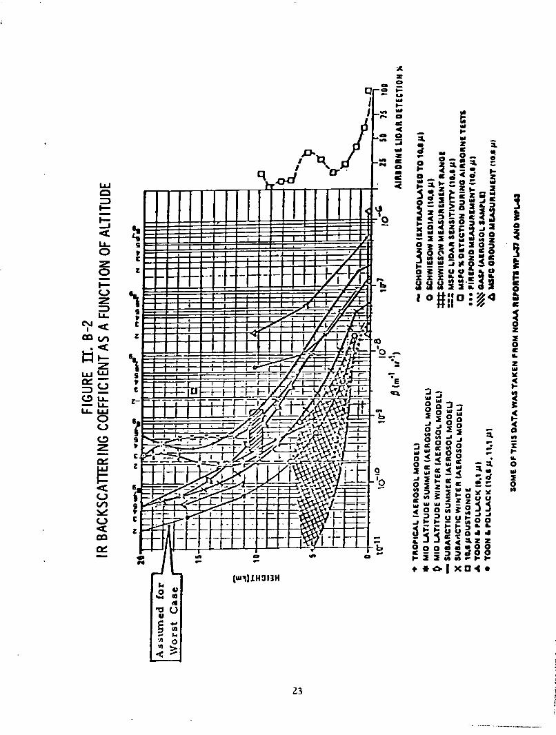
The uncertainty associated with the backscatter is mucb less well understood. Figure 1I.B-2 is a compendium of backscatter estimates from various wavelengths other than the ones of interest, with considerable reliance on the aero- sol size distribution models. In this report, calculations have been based on the assumed "worst case" curve. The pre- sence of Lidar returns does indicate the basic feasibility of the doppler lidar wind measuring technique.
FIG
URE IZ. A
-1
S IG
NAL-
TO-N
O1
SE R
ATIO
VS.
AL
TITU
DE
OR
BIT
AL
AL
TIT
UD
E =
650
(K
MI
OR
BIT
AL
INC
LIN
AT
ION
= 5
7 (D
EG
) O
PTI
CS
DIA
ME
TE
R =
1.2
5 (M
I W
AV
EL
EN
GT
H =
9.1
145 (M
ICR
O M
)
AT
TE
NU
AT
ION
= A
FG
L T
RO
PIC
AL
AB
SO
RP
TIO
N
BA
CK
SC
AT
TE
R=
MS
FC
WO
RS
TC
AS
E
SA
MP
LED
AL
TIT
UD
E, k
m

Clearly, an operational system will not be able to measure winds at all altitudes, at all times: clouds are one inhibiting factor, and there will be occasions when the concentrations of aerosols in some regions and at some alti- tudes will be insufficient to provide a useful return signal.
FIG
URE II.
B-1
MO
LECU
LAR
ABSO
RPTI
ON
COEF
FIC
IENT
(km
-1)
ATX-
9.1
145
p m
- TRO
P
- ....... *
..- M
LS
--
----
M LW
-- S A
S
---
SA
W
10al
0 1
2 I 4 I
6 I 8 I
10
I 12
I
14
I 16
I
18
1 20
I
AL
TIT
UD
E (km)
111. CONFIGURATION AND MASS PROPERTIES
111. CONFIGURATION AND MASS PROPERTIES
1II.A. REQUIREMENTS AND ASSUMPTIONS
The following assumptions and requirements determined the configuration design approach
(i) Beam pointing shall be realized by a scanning Cassegrainian telescope with a maximum diameter of 1.25 m. The scanning axis shall be aligned with the local vertical, and the optical axis of the telescope shall bt cffset by approximately 56 deg (the scan angle). The scan rate shali be approximately 4 rpm.
(ii) The Shuttle shall be tht: ;lunch vehicle, and the spacecraft . ; 1 be retrievable
(iii) There shall be two solar array wings of approximately 28m2 individual area, capable of both deployment and retraction.
(iv) There shall be two deployable/ retractable radiators (both sides active) with total area of approxi- mately 5.7m2
The mission equipment (laser, scan mechanism, and telescope) was assumed to be similar to the continuously scanning, one- meter, Cassegrainian configuration reported in the NOAA/LhSC WINDSAT Final Briefing Charts: a fritted glass mirror was assumed rather than the Beryllium mirror recommended by LMSC.
1II.B. CONCEPTUAL DESIGN
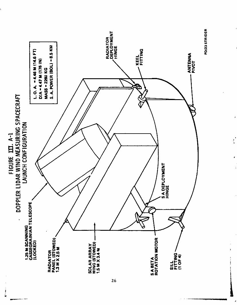
Figure 1II.A-1 illustrates the features of the conceptual configuration, as it would be stowed in the orbiter cargo bay. The cylindrical spacecraft bas the maxi- mum diameter compatible with the orbiter cargo ba:. dynamic envelope and a height of 1.5 m. The resulting internal vo1:une 'easily accommodates the mission and subsystems equip- ment, as determined by a trial layout. This "pancake" con- figuration is the result of a natural tendency to effectively utilize the cargo bay volume: it does -- not, in this instance, result from the present commercial payload STS charge policy. The driving cost factor under this policy according to per- formance calculations, would be the weight delivered to orbit
FIGU
RE I
n. A
-1
- DO
PPLE
R LI
DAR
WIN
D M
EASU
RING
SPA
CECR
AFT
12
5 M S
CA
NN
ING
LA
UNCH
CON
F1GU
RATI
ON
CA
SS
EG
RA
INIA
N T
ELE
SC
OP
E -
RA
DIA
TO
R
L.O
. A
. -4
.46
M (1
4.6
FT
) D
:A =
4.4
7 M
(176
IN)
MA
SS
= 2
260
KG
S.
A P
OW
ER (
BO
L) - 8.5
KW
DE
PLO
YM
EN
T W
NG
E
11 I
RA
DIA
TO
R
y.b
K
EE
L
FIT
TIN
G
SlL
L
FIT
TIN
G
(1 O
F 4
)
,
AN
TEN
NA
-.- --
-
PD
IZ3
ST
RID
ER
r a t h e r t h a n p a y l o a d l e n g t h . The a n t e n n a f e e d h o r n is s t o w e d i n t h e body o f t h e s p a c e c r a f t when t h e a n t e n n a is retracted: a f o l d a b l e h o r n c o u l d a l s o be u s e d t o m i n i m i z e t h e s t o w e d p a y l o a d l e n g t h .
The k e e l arid s i l l f i t t i n g s a t t a c h t o t h e p a y l o a d p r i m a r y s t r u c t u r e , o b v i a t i n g t h e n e e d f o r a s e p a r a t e l a u n c h c r a d l e . T h i s i n t e g r a t i o n of t h e l a u n c h c r a d l e LnLo t h e s p a c e c r a f t is n o t o n l y p r o g r a m m a t i c a l l y s i m p l e r , it a l so m i n i m i z e s t h e t o t a l p a y l o a d - c h a r g a b l e cargc mass. I n d o i n g so, it p e r m i t s c o n s i d e r a t i o n o f d i r e c t d e l i v e r y t o o r b i t ( a t 57 d e g ) w i t h o u t u s e o f a n u p p e r s t a g e or a n i n t e g r a l p r o p u l - s i o n s y s t e m f o r o r b i t a l t r a n s f e r ( a t l e a s t o n e , a n d l i k e l y two, orbi ter OMS k i t s would b e r e q u i r e d o t h e r w i s e ) . T h i s i s n o t t o s u g g e s t t h a t t h i s w i l l u l t i m a t e l y b e t h e p r e f e r r e d a p p r o a c h , o n l y t h a t t h i s is o n e o p t i o n . The s i l l f i t t i n q s are s p a c e d 59 i n c h e s a p a r t (as o n a s t a n d a r d ESA p a l l e t ) t o p r o v i d e t h e maximum number o f p o s s i b l e a t t a c h p o s i t i o n s i n t h e c a r g o bay . A g r a p p l e f i x t u r e ( n o t shown) is p r o v i d e d t o a l l o w d e p l o y m e n t / r e t r i e v a l u s i n g a remote m a n i p u l a t o r arm.
The t e l e s c o p e , r a d i a t o r s , a n d f o l d e d solar a r r a y s are mounted o n o n e f l a t s i d e o f t h e " p a n c a k e " s p a c e - c ra f t a n d s e c u r e d by l a u n c h l o c k s . The r a d i a t o r s ro ta te 1 8 0 d e g d u r i n g d e p l o y m e n t i n t o t h e p o s i t i o n i l l u s t r a t e d i n t h e a r t i s t s ' c o n c e p t i n F i g u r e 1 . A - 1 . S i m i l a r l y , t h e so la r a r r a y w i n g s a re mounted o n s h o r t a-ms a n d ro ta te 1 6 0 d e g a b o u t t h e i l l u s t r a t e d h i n g e p o i n t s before u n f o l d i n g t o t h e i r o p e r a - t i o n a l p o s i t i o n . The a n t e n n a is mounted on t h e r e m a i n i n g f l a t s i d e o f t h e s p a c e c r a f t .
1 I I . C . s Y S T P l S I Z I N G
S u b s y s t e m a n d s p a c e c r a f t mass estimates are g i v e n i n t h e f o l l o w i n g T a b l e : t h e s e masses a re b a s e d o n t h e m i s s i o n e q u i p m e n t masses t a k e n from t h e NOAA/LMSC WINDSAT S t u d y F i n a l B r i e f i n g C h a r t s , s u b s y s t e m mass estimates, a n d t h e a s s u m p t i o n o f a n a l l - aluminum s p a c e c r a f t s t r u c t u r e .
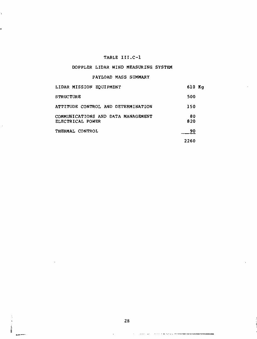
TABLE 1 I I . C - 1
DOPPLER L I D A R WIND MEASURING SYSTEM
PAY LOAD MASS SUMMARY
L I D A R M I S S I O N EQUIPMENT
STRUCTURE
A T T I T U D E CONTROL AND DETERMINATION
COMMUNICATIONS AND DATA MANAGEMENT ELECTRICAL POWER
THERMAL CONTROL

1V.A. ET-ECTRICAI, POWER SUBSYSTEM
IV. A . 1 REQUIREMENTS AND ASSU-WTIONS
Conceptual design and analysis of the electrical power sp~hsys~em requires definition of the loads (power and voltage), orbit (altitude and inclination), and mission fac- tors such as mission duration and spacecraft pointing.
For the doppler lidar wind measuring system spacecraft, the loads were estimated as:
Guidance and Navigtion 227 -- 247 W
Communications and Data Manrgement 110 - 115 W
Thermal Control 360 W
Mission Equipment 2140 - 2346 W Totals 2827 - 3068 W
The subsystem estimates are based on representa- tive equipment selections by subsystem engineers. The ther- mal control power requirement is highly conservative, being based on the startup power for a gas pump. The mission equipment power estimates were taken from the September 198G NOAA/LMSC WINDSAT Final Briefing Charts.
A design margin of 15-25% is customary in pre- liminary design activity to allow for uncertainties which almost invariably lead to growth in power requirements as th= design matures. Using 3500 W as the total electrical power requirement yields a 24% and a 14% margin relative to the low and hig3 estimates, respectively, of the last paragraph. On balance, this estimate is slightly more conservative than usual. The EPS design is not sensitive to small departures trom this value, whose adopt.ion obviates the unenl ightening production of many tables and equipment lists tailored to minor differences i ~ , the ,-.ases considere ;.
The choice of orbit has two primary effects upon EPS design: first, the solar array and battery system must be sized to supply exlipse load?; secund, the altitude, in- clination, and launch date (within the solar cycle) affect the particulate radiation, which degrades the solar array. A lower orbit gives a lower light/ dark ratio (requiring a lar- ger array and battery system) whereas a higher orbit yields greater radiation damage due to geomagnetically trapped particles. For this study, a three--year mission coinciding
w ~ t h a peak period of solbr activity was assumed, so that flare protons were a majar contributor to the array degradation.
Five orbits were analyzed to scope the character- istics of a conceptual EPS design:
ORBIT ALTITUDE INCLINATION NCDE # (km; (deg) - (hr)
1 800 sun-synch 0600
2 650 sun-synch 0600
3 800 sun-synch 1200
The fSrst and third of these represent the best- and worst-cases, respectively, for a high-inclination, 800 kin orbit (as per the NOAA WPL-37 and -63 reports). The 0600 node maximizes the day/night ratio (yielding the "minimum" EPS) while the 1200 node has the opposite effect. The second oroit was analyzed to assess the sensitivity of the EPS to orbital altitude at the most favorable nodal position. The fourth a-d fifth orbits were analyzed to bound the EPS char- acterist-cs in orbits potentially accessible from KSC: nodal ~osition is not an EPS driver at the 57 deg inclination.
1V.A. 2. CONCEPTUAL DESIGN
The relatively large power requirement of 3500 W and the local vertical orientation of the telescope scan axis necessitates an oriented (sun-tracking) solar array. Two rotational degrees of freedom are used to maximize the array output: roll about t!le scan axis and rotation of the solar arrays. The first of these is ccmpatible with the need to minimize the sunlight incident on the radiators. Rotation of the solar axrays implies use of solar array drive mechanisms and power transfer devices (such as slip rings or flex cables). These solar array components have been developed for many programs, and there is ample experience for the present application.
A variety of power distribution and control schemes are possible: the concept described here is not necessarily optimum, but is adequate to provide estimates of the realizable efficiencies, weights, and dimensions.
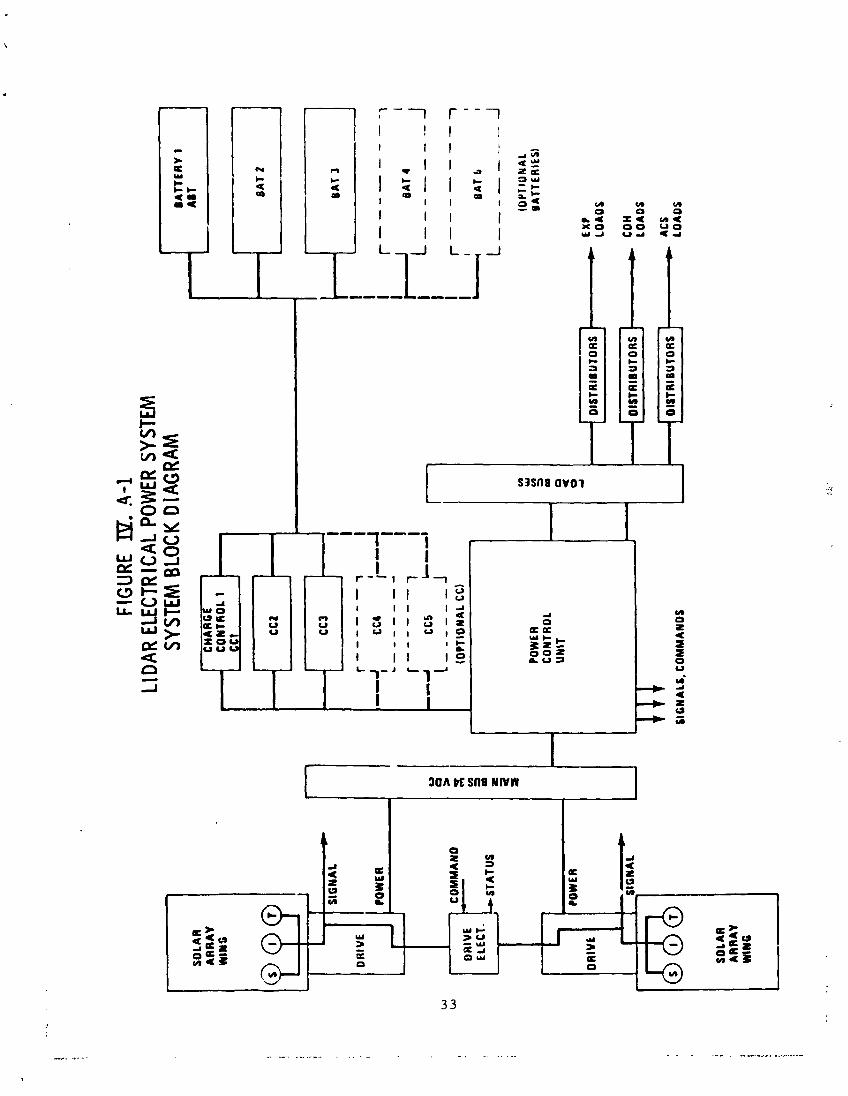
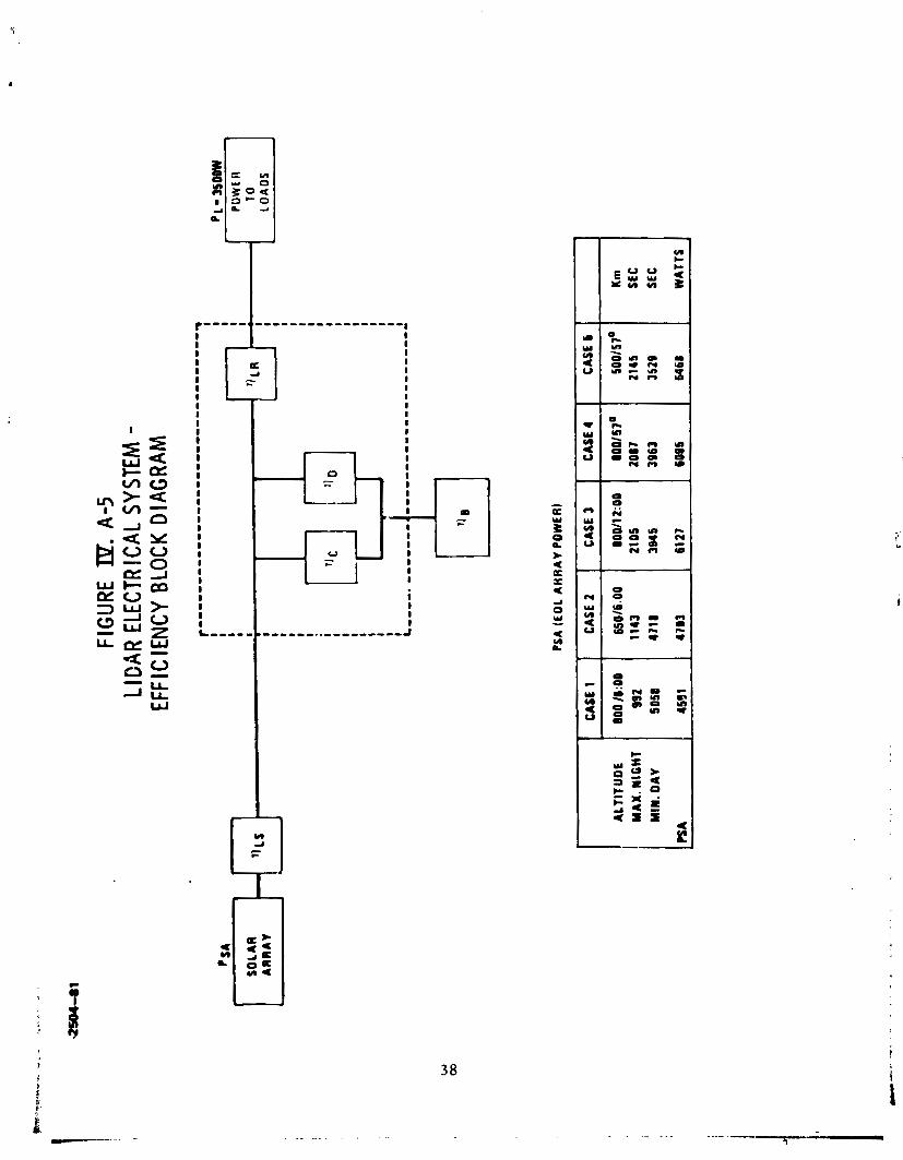
F i g u r e 1 V . A - 1 i l l u s t r a t e s t h e c o n c e p t . S o l a r a r r a y power is t r a n s f e r r e d v i a s l i p r i n g s or f l e x c a b l e s t o t h e ma in power b u s a t a n o m i n a l 3 4 Vdc ( v a r y i n g w i t h a r r a y t e m p e r a t u r e ) . The power c o n t r o l u n i t (PCU) p r o v i d e s command, c o n t r o l , a n d p r o t e c t i o n f u n c t i o n s . D u r i n g t h e d a y l i g h t p o r - t i o n o f t h e o r b i t , t h e PCU r o u t e s solar a r r a y power t o t h e b a t t e r y c h a r g e c o n t r o l l e r s ( C C s wh ich p r o v i d e a c h a r g e / d i s c h a r g e p a t h f o r t h e N i C d b a t t e r v a s s e m b l i e s . The PCU a l so r o u t e s power f r o m t h e s o l a r a r r a y (or b a t t e r y , a t n i g h t ) t o t h e m u l t i p l e l o a d b u s e s w h i c h , i n t u r n , d i s t r i b u t e power t o t h e v a r i o u s u s e r s . The l o a d b u s e s i n t e r f a c e l o a d s t h r o u g h r e m o t e l y l o c a t e d d i s t r i b u t o r s w h i c h p r o v i d e l o c a l s w i t c h i n g , i s o l a t i o n , a n d p r o t e c t i v e f u n c t i o n s . No te t h a t t h i s d i s t r i - b u t i o n scheme d i s t r i b u t e s u n r e g u l a t e d power a t 22-34 d c ( d e p e n d i n g o n a r r a y t e m p e r a t u r e a n d b a t t e r y s t a t e o f c h a r g e ) . The v a r i o u s l o a d s mus t t h e n p r o v i d e t h e i r own power s u p p l i e s ( d c - d c ) , wh ich is n c t t r u e f o r a d i s t r i b u t i u t ~ scheme ta i lored t o t h e case w h e r e a l l l o a d s r e q u i r e a s p e c i f i c , r e g u l a t e d ( u s u a l l y 28 Vdc) s o u r c e . I n t h e p r e s e r t a p p l i c a t i o n , t h e l i d a r is t h e m a j o r power u s e r , r e q u i r i n g h i g h power , h i g h v o l t a g e s u p p l i e s . The r e g u l a t 2 d b u s a p p r o a c h wou ld h a v e t h e d i s a d v a n t a g e o f r e g u l a t i n g t h e power t w i c e , y i e l d i n g a l o w e r o v e r a l l c o n v e r s i o n e f f i c i e n c y .
F i g u r e 1 V . A - 1 i n d i c a t e s o p t i o n a l c h a r g e c o n t r o l - lers a n d b a t t e r i e s . T h i s r e f l e c t s t h e d i f f e r e n t e n e r g y s tor- a g e r e q u i r e m e n t s of t h e c a n d i d a t e o r b i t s . An o ~ e r a t i o n a l s y s t e m w i t h s e v e r a l s p a c e c r a f t a t d i f f e r e n t n o d e s c o u l t , h a v e a cominon power s y s t e m w i t h d i f f e r e n t e n e r q s t o r a g e c a p a c i t i e s .
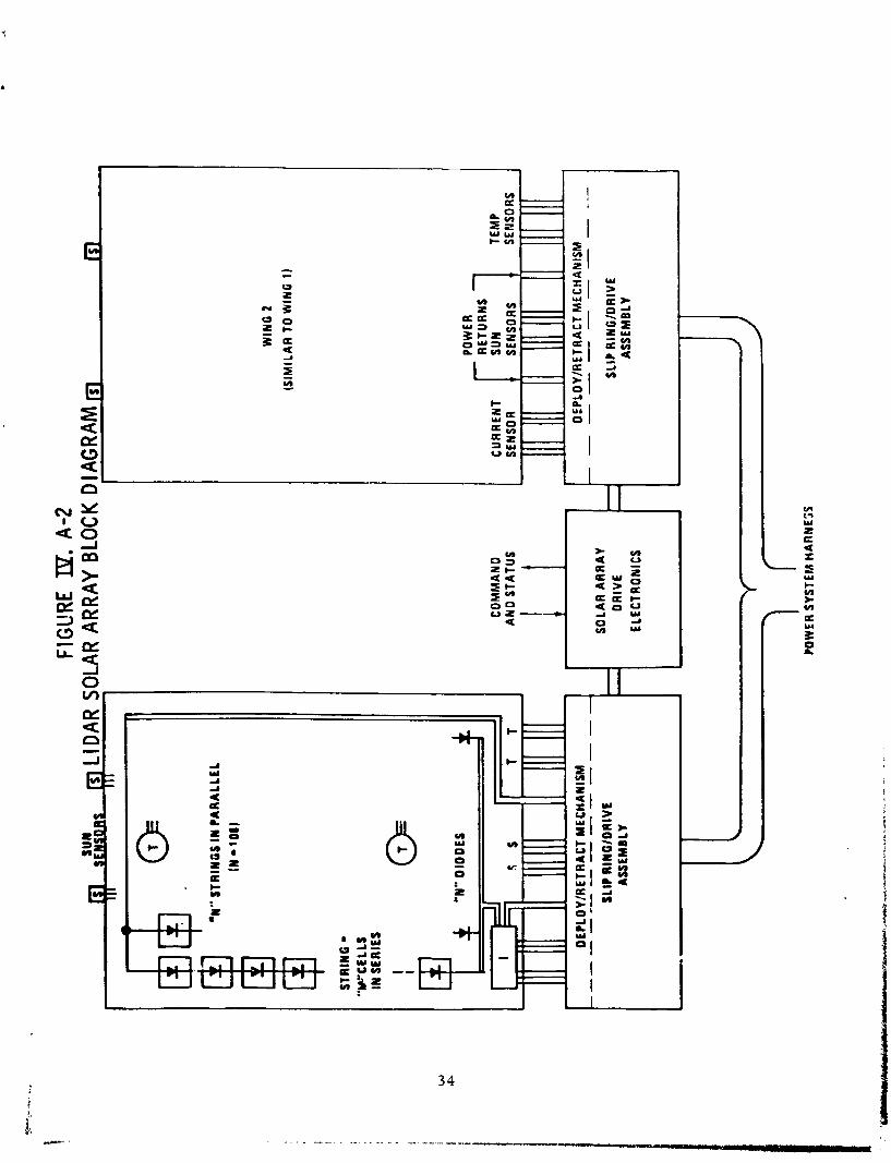
F i g w e IV.13-2 i l l u s t r a t e s t h e s o l a r a r r a y con- c e p t , h a v i n g two i d e n t i c a l w i n g s e q u i p p e d w i t h d e p l o y / r e t r a c t mechanisms a n d power t r a n s f e r / d r i v e mechanisms f o r s u n o r i e n - t a t i o n a n d power t r a n s f e r . Each wing c o n s i s t s o f a number o f subn iodu le s f o r ease o f m a n u f a c t u r e , a s s e m b l y , a n d l a u n c h . The s u b m o d u l e s a re a s s e m b l i e s o f solar ce l l s , v a r i o u s t e r m i - n a l s , d i o d e s , a n d h a r n e s s w i r i n g f e a t u r e s . Some s u b m o d u l e s also i n c o r p o r a t e t h e r m a l a n d c u r r e n t s e n s o r s f o r a r r a y d i a g - n o s t i c s . Sun s e n s o r s o n e a c h wing p r o v i d e t h e s o l a r c r i e n t a - t i o n s i g n a l s n e e d e d by t h e so lar a r r a y d r i v e e l e c t r o n i c a s s e n l b l y mounted w i t h i n t h e s p a c e c r a f t .
Power a n d s i g n a l s a re r o u t e d t o t h e s p a c e c r a f t by a "power s y s t e m h a r n e s s " .
IV.A.3. SYSTEM SIZING
The f i r s t s t e p i n s y s t e m s i z i n g is t h e d e t e r m i - n a t i o n o f t h e e n d - o f - l i f e s o l a r a r r a y power r e q u i r e m e n t a n d
FIGU
RE IP. .4
-1
SOLA
R
AR
RA
Y
WIN
G
Ll DA
R EL
ECTR
ICAL
POW
ER S
YSTE
M
SYST
EM B
LOCK
DIA
GR
AM
r T
SOLA
R
AR
RA
Y
-
BA
TTE
RY
1
A8 T
WIN
G
CH
AR
GE
I
L
J b
1
BA
T 2
CO
NTR
OL
1
7
- r-'
SIG
NA
L
DR
IVE
POW
ER
W
w
CO
MM
AN
D
DR
IVE
-
b C
Cl CC
3
U
0
>
3
M
I L I
-
I
CC
2
I r-
----
-7
I J
I cc
4 !-
-J
\
I
.------*
I I
r--------I
! B
AT
4 1
r---
---7
--d
I C
C5
LII!
WL
- - - - - - --
I I
J L-
----
- J
(OPT
ION
AL
CC
) I
r------- 1
\ I
I t
ELEC
T. ,
STA
TUS
4
I
OlS
T RIB
UTO
RS
SIG
NA
LS, C
OM
MA
ND
S LO
AD
S
s
m 5 I
-
- O
RlV
k f
1
POW
ER
S-
-
c
COH
LOA
DS
V)
W
U) 3
10
o
a
0 4
POW
ER
CO
NTR
OL
UN
IT
4
BA
T b
I
L ,,------
J
IOP
IIO
NA
L B
ATT
ERIE
S)
OIS
TRIB
UTO
RS
EX
P
LOA
OS
FIG
URE 19.
A-2
WlN
G 2
(SIM
ILA
R T
O W
lNG
1)
POW
ER S
YSTE
M H
AR
NES
S
OLA
R AR
RAY
BLO
CK D
IAG
RAM
m
-
'N"
STR
ING
S IN
PA
RA
LLE
L
POW
ER -
RET
UR
NS
CO
MM
AN
D
CU
RR
ENT
SUN
A
ND
STA
TUS
SENS
OR
T EM
P
y SE
NSO
RS
y SE
NSO
RS
I I,
111 111
II 111
111
11 111
111
. 4
- O
EIL
OY
/RE
TRA
CT
MEC
HA
NIS
M
DEP
LOY/
RLT
RA
CT
MEC
HA
NIS
M
----------
----
A _ - - - - - - -
SLIP
RIN
Q/D
RIV
E
SOLA
R A
RR
AY
7
-
-
DR
IVE
SL
IP R
ING
IDR
IVE
A
SSEM
BLY
1
ASS
EMB
LY
ELEC
T RO
NlC
S
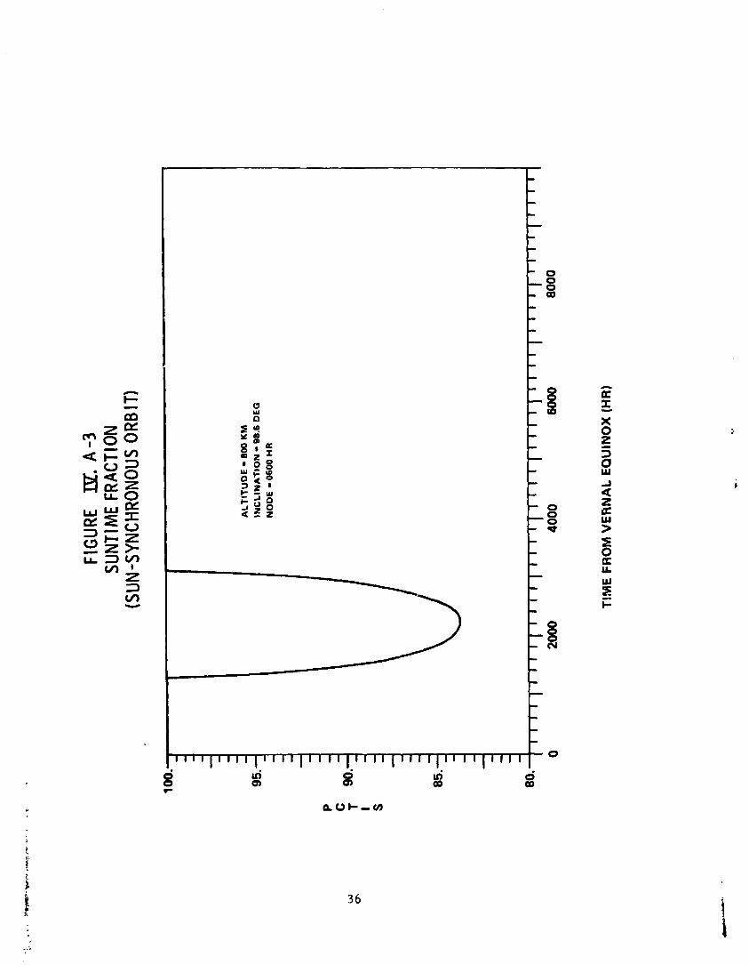
energy storage capacity requirement. Apart from relatively standard allowances for conversion and transmission efficien- cies, the variation in the suntime fraction during the year must be accounted for. This fraction is shown in figures 1V.A-3 and 1V.A-4 as "percent time in sunn (PCTIS). For an 800 km, sun-synchronous, orbit with an 0600 hr node, Figure 1V.A-3 shows that the spacecraft is continuously in the sun except for a period of about 75 days centered around the summer solstice, when the minimum orbital suntime percent is 83.6%. In contrast, Figure 1V.A-4 shows that a spacecraft in an 800 km, 57 deg orbit is occulted on almost every orbital revolution, frequently by as much as 35%. Figure 1V.A-5 defines the end-of-life solar array power requirements associated with the candidate orbits.
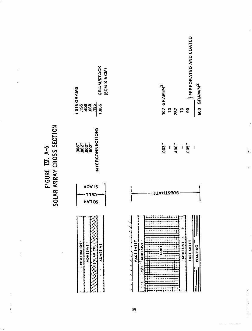
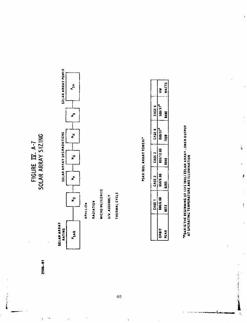
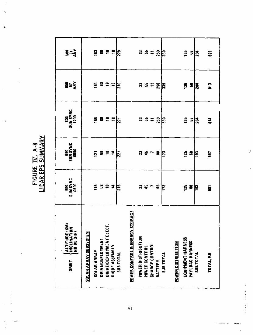
Figure 1V.A-6 shows a cross-section of the solar array, indicating the typical components of a lightweight, rigid honeycomb core type panel. Detailed test data on high- efficiency solar cells (from JPL) were used to select the baseline solar cell and to establish the electrical and ther- mal operating points (The cell conversion efficiency is sensitive to the cell temperature: at high temperatures, the voltage drops rapidly and, while the current increases slightly, the next effect is decreased output power at the operating point.). Application of estimated degradations due to irradiation and thermal cycle and micrometeorite damage, together with allowances for Earth orbit eccentricity, assembly losses, interconnections, panel layout and accessory components, yields an estimate of the beginning-of-life (BOL) array output requirement. This estimate of the array size also allows estimation of the total wire length/mass connect- ing the array to the spacecraft. Figure 1V.A-7 defines the BOL power requirement for the various orbits considered. Figure 1V.A-8 defines the corresponding total EPS masses: the primary differences are due to
(1) additional battery capacity for increased night times, and
( 2 ) additional solar array area to charge the extra battery capacity.
1V.B COMMUNICATIONS AND DATA MANAGEMENT
IV :B. 1 DATA RATES
The maximum data rate requirements for the CDMS can be derived straightforwardly by considering the temporal and spectral characteristics of the doppler-shifted pulse backscattered from the atmosphere.
FIG
URE
IP.
A-3
SU
NTIM
E FR
ACTI
ON
(SUN
-SYN
CHRO
NOUS
ORB
IT)
AL
TIT
UD
E - 80
0 KM
INC
LIN
AT
ION
- 98.6
DE
G
NO
DE
- 060
0 H
R
TlN
lE F
RO
M V
ER
NA
L E
QU
INO
X (HR)

FIGU
RE 19. A
-5
LICA
R EL
ECTR
ICAL
SYS
TEM
- EF
FIC
IENC
Y BL
OCK
DIAG
RAM
r..-.-..--.-.--.-.-.-.-.--..--.....q I
I
'SA
I
I t
I ?
I '
I p
~'3
50
0W
I
I
SO
LAR
I
ww
tn
- 91s S
~L
R - I
7 0
A
RR
AY
I
I
A L
t
LO
AD
S
I
I I
. I
I I
1 I
! I I
I 'I
c ! 'I
D
I I
I I
I I
I I
1 I
I I
I I
I I
I
I CA
SE 1
CA
SE 2
CA
SE 3
CA
SE 4
CA
SE L
I
I I
I A
LTIT
YO
E
1 M
AX
. MIG
HT
?SA
800
/8:0
0 99
2 50
50
4591
47
93
61 27
60
95
6468
I
WA
TTS
650/
6.00
11
43
4718
800/
12:0
0 21
05
3845
8001
57~
2087
39
63
5001
57~
2145
35
29
Km
SE
C SE
C
SO
LA
R A
RR
AY
R
AT
ING
FIGU
RE a. A-7
SO
LAR
ARRA
Y S
IZIN
G
SO
LAR
AR
RA
Y D
EC
RA
OA
TIO
NS
S
OLA
R A
RR
AY
PO
WE
R
RA
DIA
TIO
N
MIC
RO
ME
TE
OR
ITE
U/V
. A
SS
EM
BLY
TH
ER
MA
L C
YC
LE
PSA
R (
BO
L A
RR
AY
PO
WE
RI'
*PSA
R I
ST
HE
BE
GIN
NIN
G O
F L
IFE
IBO
L) S
OLA
R A
RR
AY
, O
WE
R O
UTP
UT
AT
OP
ER
AT
ING
TE
MP
ER
AT
UR
E A
ND
IL
LU
MIN
AT
ION
t
OR
llT
PS
AR
CA
SE 1
800/
6:0O
601 2
CA
SE 2
660/
6.00
6200
CA
SE 4
8001
57~
1908
CA
SE 3
8001
1 210
9
8040
CA
SE 6
I
500/
57O
K
M
8488
I
WA
TTS
FIG
URE IE.
A-8
LID
AR E
PS S
UM
MAR
Y
I ALT
ITU
DE
(KM
) O
RB
IT
INC
LIN
ATI
ON
N
O D
E (H
R)
SOLA
R A
RR
AY
SUBS
YSTE
M
SOLA
R A
RR
AY
DR
IVEI
DEP
LOYM
ENT
DR
IVEI
DEP
LOYM
ENT
ELEC
T.
DIO
DE
ASSE
MBL
Y SU
B TO
TAL
POW
ER C
ON
TRO
L &
EN
ERG
Y ST
ORA
GE
POW
ER D
ISTR
IBU
TIO
N
POW
ER C
ON
TRO
L CH
ARG
E C
ON
TRO
L B
ATT
ERY
SUB
TOTA
L
POW
ER D
ISTR
IBU
TIO
N
EQU
IPM
ENT
HARN
ESS
PAYL
OA
D H
ARNE
SS
SUB
TOTA
L
TOTA
L, K
G
850
SUN
SYNC
06
00
121 68
18
14
22 1 23
45 7 98
173
125 68
193
587
800
SUN
SYNC
06
00
11 5 68
18
14
21
5 23
45 7 98
173
125 68
193
58 1
800
SUN
SYNC
12
00
155 80
18
18
27 1 23
55
11
250
339
136 68
2W
814
800
57
AN
Y
1 54 80
18
18
27
0 23
55
11
250
339
136 68
500
57
AN
Y
163 80
18
18
27
9 23
55
11
250
339
136 68
I
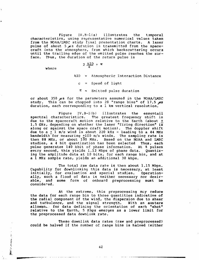
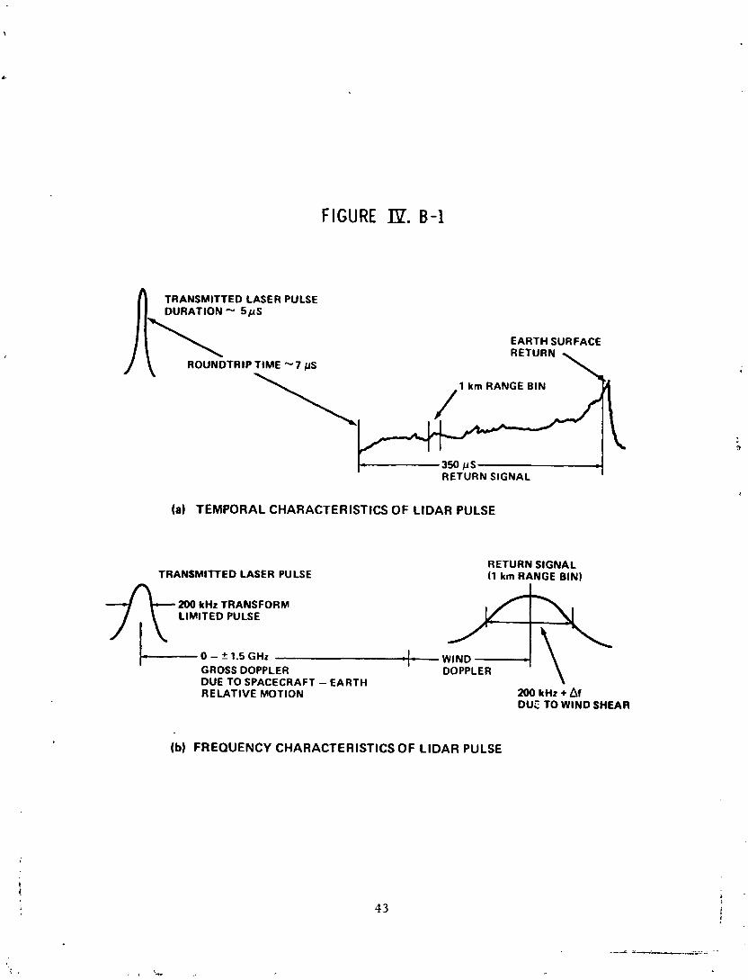
Figure 1V.B-l(a) illustrates the tzmporal characteristics, using representative numerical values taken from the NOAA/LMSC study final presentation charts. A laser pulse of about 5 y s duration is transmitted from the space- craft into the atmosphere, from which backscat.tering occurs until the trailing edge of the emitted pulse reaches the sur- face. Thus, the duration of the return pulse is
where
AID = Atmospheric Interaction Distance
c = Speed of light
r = Emitted pulse duration
or about 350 ,us for the parameters assumed in the NOAA/LMSC study. This can be chopped illto 20 "range bins" of 17.5 ,us duration, each corresponding to a 1 km vertical resolution.
Figure 1V.B-l(b) illustrates the essentail spectral characteristics. The greatest frequency shift is due to the spacecraft motion relative to the Earth (about - + 1.5 GHz, depending on whether the laser "firing direction" is along or against the space craft motion). The doppler shift due to a + 1 m/s wind is about 220 kHz - leading to a 44 MHz bandwidth for measuring +lo0 m/s winds. The sampling rate is then 88 MHz, or about 150 MHz. Based on the NOAA and LMSC studies, a 4 bit quantization has been selected Thus, each pulse generates 140 kbit of phase information. At 8 pulses evcry second, this yields 1.12 Mbps of phase data. Quantiz- ing the amplitude data at 10 bits, for each range bin, and at a 1 MHz sample rate, yields an additional 30 kbps.
The total raw data rate is then about 1.15 Mbps. Chpability for downlinking this data is necessary, at least initially, for evaluation and special studies. Operation- ally, such a flood of dat3 is neither necessary nor desir- able, and some form of onboard preprocessing must be considered.
At the extreme, this preprocessing mcy reduce the data for each range bin to three quantities indicative of the radial component of the wind, the dispersion due to shear and turbulence, and the signal strength. With an austere allowanc.: for data defining the orientation of each "shot" relative to the Earth, 5 Kbps emerges as a lower limit for the preprocessed data downlink rate.
These downlink data rates (raw and preprocessed) could be halved if the number of range bins is halved (either
FIGURE
TRANSMITTED LASER PULSE DURATION - 5 p S
EARTH SURFACE
ROUNDTRIP TIME " 7 pS
\ 1 km RANGE BIN
I-- 350 irs RETURN SIGNAL
(a) TEMPORAL CHARACTERISTICS OF LlDAR PULSE
RETURN SIGNAL TRANSMITTED LASER PULSE (1 km RANGE BIN)
200 kHz TRANSFORM LIMITED PULSE
0 - T 1.5 GHz WIND GROSS DOPPLER DOPPLER DUE TO SPACECRAFT - EARTH RELATIVE MOTION TI. * 200 DUE kHz TO + WIND Af SHEAR
(b) FREQUENCY CHARACTERISTICS OF LlDAR PULSE
by halving the vertical ranae or increasing the vertical resolution to 2 km). Conversely, if the quantization of phase data were increased from 4 to 8 bits, the downlink rates would be doubled.
1V.B. 2. TDRSS UTILIZATION
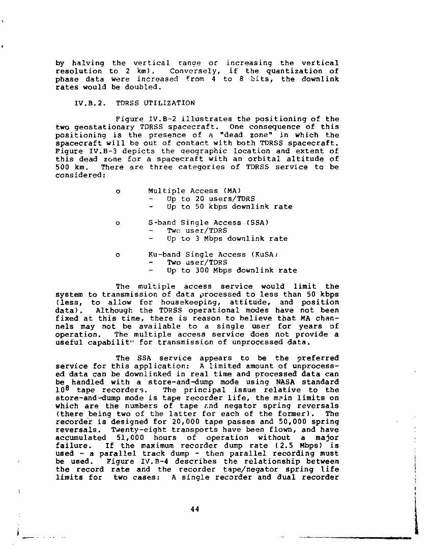
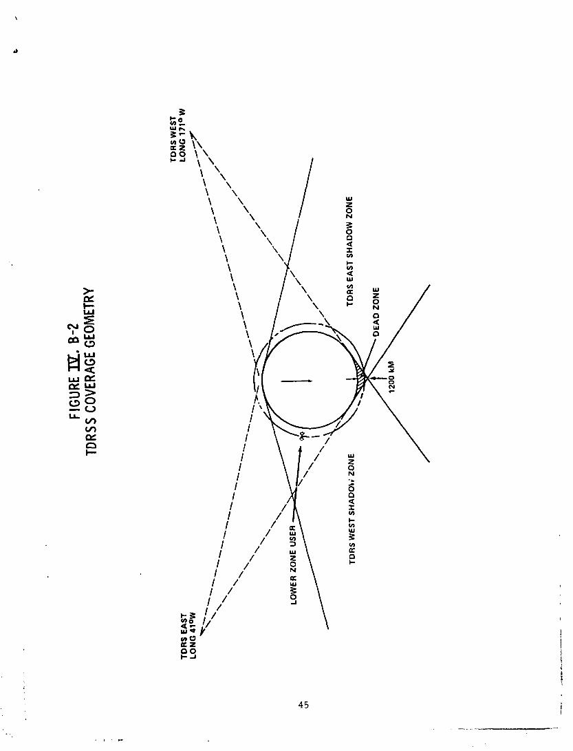
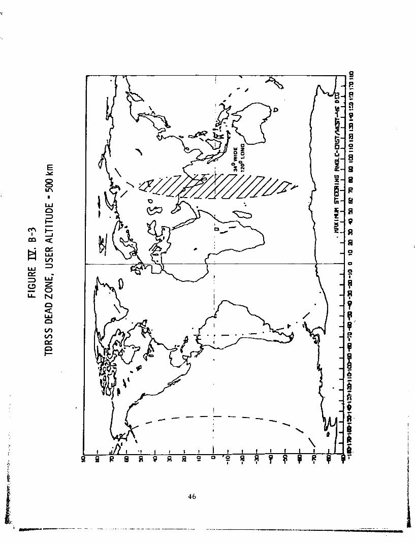
Figure 1V.B-2 illustrates the positioning of the two geostationary TDRSS spacecraft. One consequence of this positioning is the presence of a "dead zonen in which the spacecraft will be out of contact with both TDRSS spacecraft. Figure 1V.B-3 depicts the geographic location and extent of this dead zone for a spacecraft with an orbital altitude of 500 km. There are three categories of TDRSS service to be considered:
o Multiple Access (MA) - Up to 20 users/TDRS - Up to 50 kbps downlink rate
o S-band Single Access (SSA) - Twc user/TDRS - Up to 3 Mbps downlink rate
o Ku-band Single Access (KuSA) - Two user/TDRS - Up to 300 Mbps downlink rate
The multiple access service would limit the system to transmission of data ~rocessed to less than 50 kbps (less, to allow for housekeeping, attitude, and position data). Although the TDRSS operational modes have not been fixed at this time, there is reason to believe that MA chan- nels may not be available to a single user for years 9f operation. The multiple access service does not provide a useful capabilit~? for transmissi~n of unprocessed data.
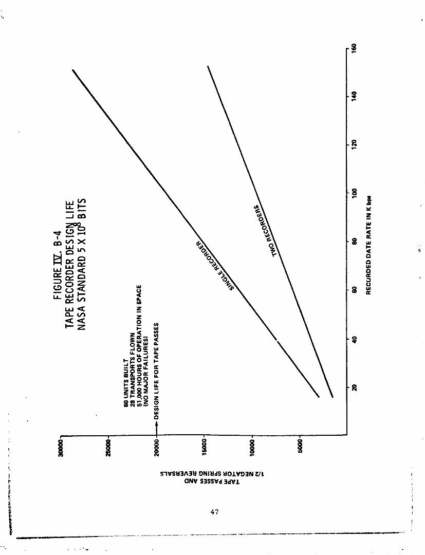
The SSA service appears to be the preferred service for this application: A limited amount of unprocess- ed data can be downlinked in real time and processed data can be handled with a store-and-dump mode using NASA standard 108 tape recorders. The principal issue relative to the store-and-dump mode is tape recorder life, the m ~ i n limits on which are the numbers of tape znd negator spring reversals (there being two of the latter for each of the former 1 . The recorder is designed for 20,000 tape passes and 50,000 spring reversals. Tv~enty-eight transports have been flown, and have accumulated 51,000 hours of operation without a major failure. If the maximum recorder dump rate (2.5 Mbps) is used - a parallel track dump - then parallel recording must be used. Figure 1V.B-4 describes the relationship between the record rate and the recorder tape/negator spring ,life limits for two cases: A single recorder and dual recorder
FIG
URE E. 0-
2 TD
RSS
COVE
RAGE
GEO
MET
RY
TO
RS
EA
ST
T
OR
S W
ES
T L
ON
G 1
71°
W
TO
RS
EA
ST
SH
AD
OW
ZO
NE
FIG
UR
EIY.
0-4
TA
PE R
ECOR
DER
DESI
G
LIFE
N
ASA
STAN
DARD
5 X
1 $ B
ITS
60 U
NIT
S B
UIL
T
28 T
RA
NS
PO
RT
S F
LO
WN
51
,000
HO
UR
S O
F O
PE
RA
TIO
N I
N S
PA
CE
(N
O M
AJO
R F
AIL
UR
ES
)
DE
SIG
N L
IFE
FO
R T
AP
E P
AS
SE
S
RE
CO
RD
ED
DA
TE
RA
TE
IN
K b
ps
operated in a flip - flop qode. Limiting the record rate to no more than 50 kbps not only provides a 50% margin on tape passes, but permits an alternate mode usable in the event of tape recorder failure: processed data would be downlinked continuously using MA service to the extent allowed by com- peting traffic (while not in a dead zone).
The technical requirements of the doppler lidar wind-measuring system are satisfied by the SSA service: this - is also the most economical approach, based on the current "softn TDRSS use charges (the charge rates used are not official but are accepted figures for planning purposes). For the MA service, assuming continuous telemetry of data processed to less than 50 kbps, the three-year mission use charge would come to $6.57 M. In contrast, the corresponding use charge for SSA with a store-and-dump mode at a 50 kbps record rate / 2.5 Mbps dump rate is $2.63 M. The S-band communication equipment is the same in either case, and three NASA standard recorders at approximately $500 K each are required for the SSA mode (two to ensure no loss of data, and an additional recorder to allow one failure without degradation of system performance). The SSA use charge may be significantly lower if the recorders can be dumped to exploit the TDRSS "as available" rates.
No need for downlinking large quantities of unprocessed data have been identified: if such a need does arise, a store-and-dump mode utilizing the KuSA service will need to be considered. The limiting factor in this instance will be the tape recorder dump rate. The Spacelab High Data Rate Recorder (HDRR) could be used; its maximum dump rate of 32 Mbps would result in a KuSA utilization rate of about 7%. At a charge of $5,00O/hr, the resulting use charge for a three-year mission is $9.2 M. The cost of the Ku-band com- munications equipment and adaptation of the HDRRs would likely equal or exceed this figure.
1V.B. 3. CDMS CONCEPT
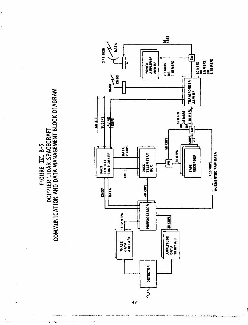
Figure 1V.B-5 illustrates the basic CDMS concept for the doppler lidar wind measuring spacecraft. Since a nominal 3-years mission is appropriate for a free-flying spacecraft, redundant hardware has been provided. The A/D converters and the preprocessor are "special purpose" items and will probably not be considered a part of the CDMS.
For routine operations, the preprocessor reduces the 1.15 Mbps stream of amplitude and phase data to a rate between 14 and 48 kbps; this preprocessed data is multiplexed with telescope and spacecraft navigation and housekeeping data to form a stream of no more than 50 kbps. This final stream is either recorded for later playback or downlinked
FIG
URE
DL B
-5
DOPP
LER LI
DAR
SPAC
ECR
An
COM
MUN
ICAT
ION
AND
DATA
MAN
AGEM
ENT
BLOC
K D
l AG
RAM
r - 1
GN
LC
,
CM
OS
DAC
S .
SUBS
YS
CE
NTR
AL
C C
3
F1
DIS
H
DA
TA
C
ON
TRO
LLE
R
A
UP
LIN
K
1 KB
PS
4
OM
Nk
2.5 M
BB
50
A
MP
LITU
DE
jg
KBP
S O
R K
BPS
L
DA
TA
10
BIT
A/D
I)
60 K
BPS
I
OR
r 26
MB
PS
O
R
TAPE
,
,-T
2.6 M
BPS
1.1 S
MBP
S 0 R
1.1
6 M
BPS
AU
GM
EN
T ED
RA
W D
AT
A
L
t 4
PHAS
E 1.
12 M
BPS
+
DA
TA
C
MO
S D
ATA
CM
DS
1 I
i
r
4 B
IT A
ID
POW
ER
AM
PLI
FIE
R
20W
RF
2 KB
PS
.
A
1 I
r - I
r >
DAC
S - DETE
CTO
R
I PR
EPR
OC
ESSO
R
TELE
ME
TRY
48
KB
PS
MU
X
L A
- 1
A
through the TDRSS MA channel. The MA service utilization capability is intended to satisfy currently unanticipated needs and to provide a means of circumventing tape recorder problems/failures. Normally, a full recorder is dumped at 2.5 Mbps while another is recording. One of the recorders can fail with no effect. After the second recorder failure, no data can be recorded while the survivor is in the dump mode - about 2% of the time if data is recorded at 50 kbps.
A secondary mode routes unprocessed amp1 i tude and phase data, augmented by telescope and spacecraft naviga- tion data, through the TDRSS SSA in near-real-time. Such data would not be transmitted while in the TljRSS dead zone. In this mode, the preprocessor also acts as a multiplexer.
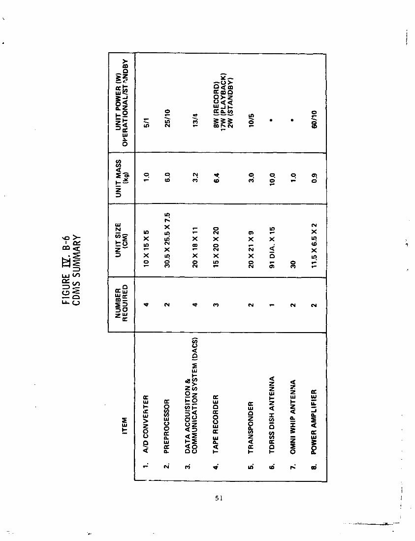
Figure 1V.B-6 is the equipment list for the CDMS. The totals for mass and power, conservatively esti- mated, are 68 kg a-.d 187 watts. If a mission profile were run, the total power to support the CDMS would be less. For instance, ane transponder was considered to be on and trans- mitting at all times, which would not be the case f ~ r a store-and-dump mode. The conservatism should have little effect on the overall spacecraft, as the CDMS power require- ment is less than 10% of the power needed for the mission equipment.
1V.C. ATTITUDE CONTROL AND DETERMINATION
1V.C. 1. ATTITUDE CONTROL REQUIREMENTS
Two distinct sets of attitude control requirements flow from the mission objectives.
For large-area wind estimation, the telescope scanning mechanism provide one element of beam pointing; the attitude control functions are then to
o align the telescope scan axis (nominally the spacecraft z-axis 1 with the local vertical (The spacecraft coordinate system is illustrated in Figure 1V.C-1) and
o roll the spacecraft about the z-axis to orient the radiators and solar arrays.
Radiator and solar array orientation is rela- tively undemanding: with the :pacecraft z-axis aligned with the local vertical, the spacecraft is rolled until the sun is in the plane of the radiators (i.e., the yz-plane). Normally prudent design practice will oversize the radiators to allow 1-3 degrees of misorientation (in any axis). This roll
FIG
URE 19.
B-6
CDM
S SU
MM
ARY
ITE
M
1.
A/D
CO
NV
ER
TE
R
2.
PR
EP
RO
CE
SS
OR
3.
DA
TA
AC
QU
ISIT
ION
&
CO
MM
UN
lCA
TlO
N S
YS
TE
M (
DA
CS
)
4.
TAP
E R
EC
OR
DE
R
5.
TR
AN
SP
ON
DE
R
6.
TDR
SS
DIS
H A
NT
EN
NA
7.
OM
Nl W
HIP
AN
TE
NN
A
8.
PO
WE
R A
MP
LIF
IER
NU
MB
ER
R
EQ
UIR
ED
4 2 4 3 2 1 2 2
UN
IT S
IZE
(CM)
10
X1
5X
5
30.5
X 2
5.5
X 7
.5
20 X
18
X 1
1
15
X2
0X
20
20
x2
1 X
9
91 D
IA. X
15
30
11.5
X6
.5 X
2
UN
IT M
AS
S
(kg
)
1 .O
6.0
3.2
6.4
3.0
10.0
1 .O
0.9
UN
IT P
OW
ER
(W
) O
YE
RA
TIO
NA
LB
T~
ND
BY
511
2511
0
13/4
8W (R
EC
OR
D)
17W
(P
LA
YB
AC
K)
2W (S
TA
ND
BY
)
1015
60/1
0
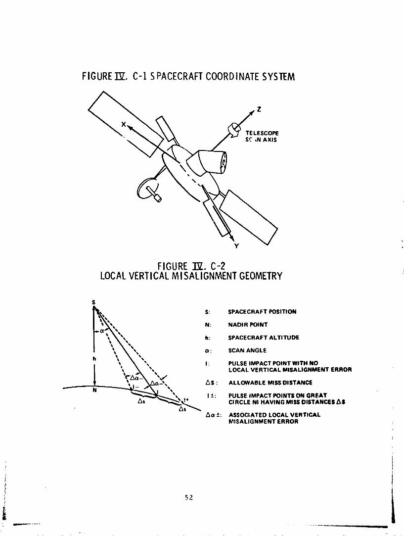
FIGURE TJZ. C-1 S PACECRAFT COORDINATE SYSTEM
T ELESCOPE SC rN AXIS
FIGURE IX. C-2 LOCAL VERTICAL MISALIGNMENT GEOMETRY
S: SPACECRAFT POSITION
N : NADIR POINT
h: SPACECRAFT ALTITUDE
a : SCAN ANGLE h
I : PULSE IMPACT POINT WITH NO LOCAL VERTICAL MISALIGNMENT ERROR
t /
A s : ALLOWABLE MISS DISTANCE N
I +: PULSE IMPACT POINTS ON GREAT CIRCLE N I HAVINC; MIS DISTANCES A8
Acu 5 : ASSOCIATED LOCAL VERTICAL MISALIGNMENT ERROR
maneuver also orients the solar arrays: the rotational capability (beta-angle conpensating) provided for these will then maximize the output power. Again, a misorientation of 1-3 degrees will have no significant effect.
No firm requirement for the alignment error of the z-axis and local vertical has been derived from the large area wind measurement objective. Obviously, the error should nat be so great that some of the lidar pulses miss the Earth entirely. This consideration leads to an upper bound of 5-10 degrees for the allowable error. A tighter bound will he necessary, for the return signal from pulses which reach the horizon will have too low a signal-to-noise ratio to be use- fuT (at least at the lower altitudes).
A tentative criterion for the alignment error can be based on the observdtion that the reference pulse rate and scan rate irnply an "average" Earth surface sample area of about 50 km x 50 km. This suggests that each pulse should strike the surface within 25 km of the point it would strike if there were no error. Figure 1V.C-2 illustrates the geome- try. If the allowable miss distance is 25 km, the corres- ponding allowable angular misalignment is 5 mrad at a space- craft altitude of 800 km, 3.9 mrad at 550 km. A constant, or slowly varying, error of this magnitude may not be important, depending on the orientation of the error. For example, referring to Figure 1V.C-2, suppose the spacecraft velocity vector is in the plane of the paper, directed to the right. The error the^ lies in the orbital plane, and the effect is to shift the scan pattern forward or backward along the ground track. On the other hand, suppose the velocity vector is perpendicular to the plane of the paper. The error is now normal to the orbital plane, and the effect is to shift the ground track left or right. The effect of the pattern shift of this magnitude along the ground track poses no problems in itself; the same is true of a crosstrack shift so long as no large coverage gaps are introduced. The overlapping of coverage swaths away from the equator suggests that a con- stant or slowly -varying crosstrack local vertical alignment error of 4-10 mrad is tolerable.
A ftrther tightening of the local vertical alignment error requirement may arise from consideration of the lag angle miscompensation resulting from the error. This miscompensation will likely be dependent on the design of the lag angle compensator/beam steering subsystem. In any event, the resulting error will reduce the SNR of the return.
As noted in Section I.C., the requirements for the second mission objective ii.e., a capability for inten- sive local observation) are poorly defined at this point, with ground truthing and localized meterological phenomena being the obvious considerations. The technique c~irently
envisioned for realizing this objective entails halting the telescope scan, locking the telescgpe, discontinuing lag angle compensation, and pointing the telescope axis at an atmospheric targic by using the attitude control system. The definition of the 10 km horizontal resolution (i.e., 10 km x 10 km surface-level target) mentioned in the WPL-37 and -63 reports seems to have been chosen with "ground truthingm in mind: such a target might be reasonably studied by ground- based, balloon-, and aircraft-borne sensors, and the results compared to observations from space.
There are some obvious p: ints to be considered in connection with localized obsertrations. If the atmospher- ic volume to be observed is small (a few tens of kilometers) and located in the orbital plane, the crosstrack cdmpocent of the wind cannot be measured reliably. If the voluz~e is not in the orbital plane, and the angle between the local verti- cal from the spacecraft and the spacecraft-to-target line-of- sight is greater than the operational scan angle, then the SNR will be reduced, with accompanying reduction in wicd measuring accuracy. Also, a given small atmosphere target will not be viewable "on demand": if located at the equator, as much as twelve hours could elagsz between viewing oppor- tunities (assuming a single spacecraft).
To avoid having +'*is secondary mission objective become a design driver, fur Lher def ini tion of observational needs is required, particularly considering the potential for ground truthing by inference.
The WPL-37 report discusses a pointing jitter requirement of 2 prad/5 msec - which would permit efficient heterodyning, by ensuring overlap of the transmitter and receiver fields of view. The 5 msec here is intended to be representative of the pulse roundtrip time, and the 2prad is to include errors Cce to structural vibrations, lag-,angle miscornpensation, and scan mirror jitter. Although a require- ment of this order is considered achievable, the detailed structural analysis needed for verification is beyond the scope of thj s assessment activity.
1V.C. 2. ATTITUDE DETERMINATION REQUIREMENTS
Knowledge of spacecraft attitude and posi~ion is required for control purposes (e.g., to calculate the orien- tation of the local vertical in spacecraft coordinates), for gross doppler removal via the frequency synthesizer, and for vector resolution of the horizontal wind. The allowable un- certainty in local vertical alignment corresponding to a hor- izontal wind uncertainty A W is given by the approximation
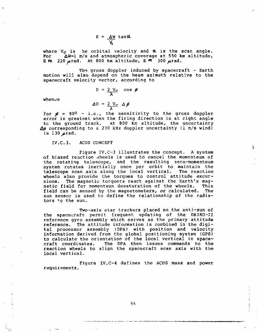
E = A W tand - vc
where Vc is he orbital velocity and oL is the scan angle. For nW=l m/s and atmospheric coverage at 550 km altitude, E m 220prad. At 800 km altitude, E M 300prad.
The gross doppler induced by spacecraft - Earth motion will also depend on the beam azimuth relat.tve to the spacecraft velocity vector, according to
D = 2 V c COSB 3-
whence AD = 2 Vp A #
h for # = 900 - i.., the sensitivity to the gross doppler error is greatest when the firing direction is at right angle tc the ground track. At 800 km altitude, the uncertainty
A# corresponding to a 220 kHz doppler uncertainty (1 m/s wind) is 130prad.
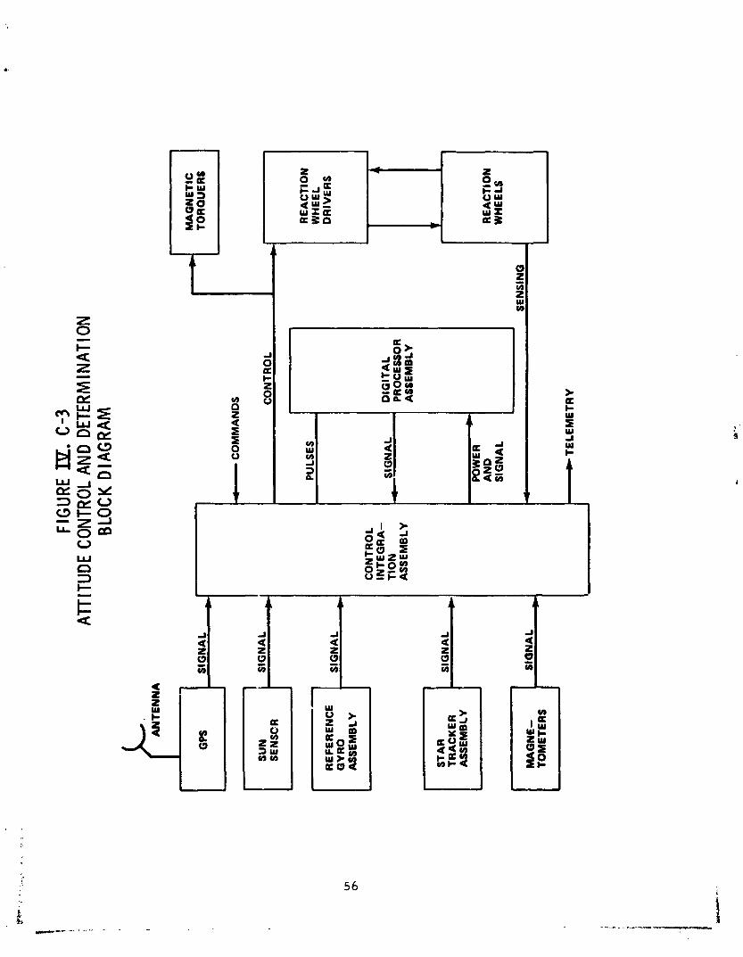
IV. C .3. ACDS CONCEPT
Figure 1V.C-3 illustrates the concept. A system of biased reaction vrheels is used to cancel the momcnteum of the rotating telescope, and the resulting zero-momenteum system rotates inertially once per orbit to maintain the telescope scan axis along the local vertical. The reaction wheels also provide the torques to control attitude excur- sions. The magnetic torquers react against the Earth's mag- netic field for momenteum desaturation of the wheels. This field can be sensed by the magnetometers, or calculated. The sun sensor is used to define the relationship of the radia- tors +o the sun.
Two-axis star trackers placed on the anti-sun of the spacecraft permit frequent updating of the D R I R l J - I 1 reference gyro assembly which serves as the primary attitude reference. The attitude information is combined in the digi- tal processor assembly (DPA) with position and velocity information derived from the global positioning system (GPS) to calculate the orientation of the local vertical in space- craft coordinates. The D P A then issues commands to the reaction wheels to align the spacecraft scan axis with the local vertical.
Figure 1V.C-4 defines the ACDS mass and power requirements.
FIG
URE ISL
. C
-3
Alll
TUD
E C
ONTR
OL A
ND D
ETER
MIN
ATIO
N BL
OCK
DIA
GR
AM
AN
TE
NN
A
C-a S
IGN
AL
s
SE
NS
CR
AS
SE
MB
LY
TRA
CK
ER
S
IGN
AL
AS
SE
MB
LV
El-
M
AG
NE
- TO
ME
TER
S
CO
NTR
OL
INT
EG
RA
- T
ION
A
SS
EM
BLY
I_ C
OM
MA
ND
S
MA
GN
ET
lC
TOR
QU
ER
S
CO
NT
RO
L
I

FIG
URE 19.
C-4
AT
TITU
DE A
ND P
OSI
TIO
N D
ETER
MIN
ATIO
N SU
MM
ARY
SE
NS
OR
S
- S
TA
R SENSOR
- S
UN
SH
AD
E
- S
UN
SE
NS
OR
- G
YR
O P
AC
KA
GE
- G
PS
- G
PS A
NT
EN
NA
S
- M
AG
NE
TO
ME
TE
RS
CO
NT
RO
LL
ER
S
- R
EA
CT
ION
WH
EE
LS
- M
AG
TO
RQ
UE
RS
PR
OC
ES
SO
R
NO
. RE
QU
IRE
D
2 2 2 1 1 2 2 4 3 1
PO
WE
R (
W)
22
2 1 20
40
25 2 36
SIZ
E (C
M 1
17.8
X 1
9.1
X 4
0.6
- - 30
.5 X
30.
5 X
22.
9
30.5
X 3
0.5
X 3
0.5
20.1
AC
RO
SS
.
-
35.6
DIA
X 2
0.3
2.5
DIA
X 1
00.1
24.1
X 2
4.1
X 2
6.7
WE
IGH
T (K
G)
9.1
2.3
15.9
16.8
2.0
3.0
15.9
5.9
9.1
V . M I S S I O N O P E R A T I O N S AND PERFORMANCE
V. MISSION OPERATIONS AND PERFORMANCE
V . A WIND ACCURACY REQUIREMENT: O R B I T SELECTION
Consideration of WPL-37 and -63 yields the fol- lowing conclusions:
o The sensitivity of achievable wind accuracy to orbital altitude and inclination has not been established.
o This sensitivity is dependent, probably in a vital manner, on atmospheric attenuation and backscatter.
Additionally, whereas prior analyses have consistently con- sidered an 800 km, high-inclination operational orbit
o Simplified analyses indicate that lower orbital hltitudes and inclinations may be possible witt- out important degradation of wind measurement accuracy; some enhancement may be possible.
o Future trade studies of orbital altitude and in- clination versus wind accuracy should be based on simulations of the type described in the WPL reports. Even with scch an approach, definite conclusions may be difficult to achieve, due to the uncertainties introduced by imperfectly understood atmospheric phenomena, particularly backscatter.
The remainder of this section interprets wind accuracy as a system figure of merit and traces its (concept- ually straightforward) relationship to orbital altitude and inclination. Also, a sun-synchronous and a 57 degree orbital inclination are compared, using various simplifications.
The primary filnction of the proposed doppler lidar wind measuring system is that of estimating the mean (= average) wind in an atmospheric volume called a resolution element - typically, a horizontal "slab" 1 km deep and 100- 500 km on a side. This is done by calculating a (suitably weighted) average of the estimates from a number of pulses (shots)' directed into the resolution element from different points along the orbit. From theory, the error in the esti- mate of the average should decrease as the number of shots is increased, i.e.,
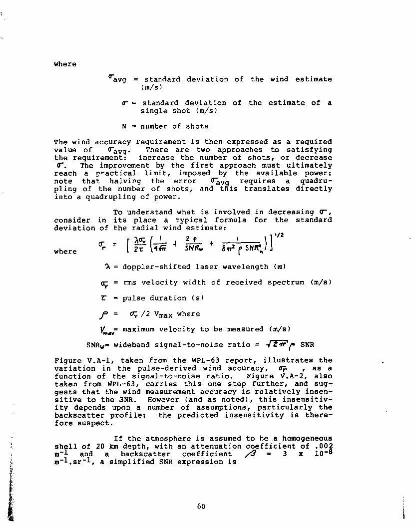
where
v avg = standard deviation of the wind estimate (m/s)
r = standard deviation of the estimate of a single shot (m/s)
N = number of shots
The wind accuracy requirement is then expressed as a required value of ravg. There are two approaches to satisfying the requirement: increase the number of shots, or decrease (r. The improvement by the first approach must ultimately reach a ~ractical limit, imposed by the available power: note that halving the error Cavg requires a quadru- pling of the number of shots, and this translates directly into a quadrupling of power.
To understand what is involved in decreasing r, consider in its place a typical formula for the standard deviation of the radial wind estimate:
I
where
?r = doppler-shifted laser wavelength (ml
5 = rms velocity width of received spectrum (m/s)
Z: = pulse duration (s)
p = / 2 Vmax where
= maximum velocity to be measured (m/s) vm.*
SNRw= wideband signal-to-noise ratio = m r SNR Figure V.A-1, taken from the WPL-63 report, illustrates the variation in the pulse-derived wind accuracy,, , as a function of the signal-to-noise ratio. Figure V.A-2, also taken from WPL-63, carries this one step further, and sug- gests that the wind measurement accuracy is relatively insen- sitive to the SNR. However (and as noted), this insensitiv- ity depends upon a number of assumptions, particularly the backscatter profile: the predicted inser~sitivity is there- fore suspect.
If the atmosphere is assumed to he a homogeneous shell of 20 km depth, with an attenuation coefficient of .002 m-1 and a backscatter coefficient f l = 3 x 10⁻⁸ rn-l.sr-l, a simplified SNR expression is
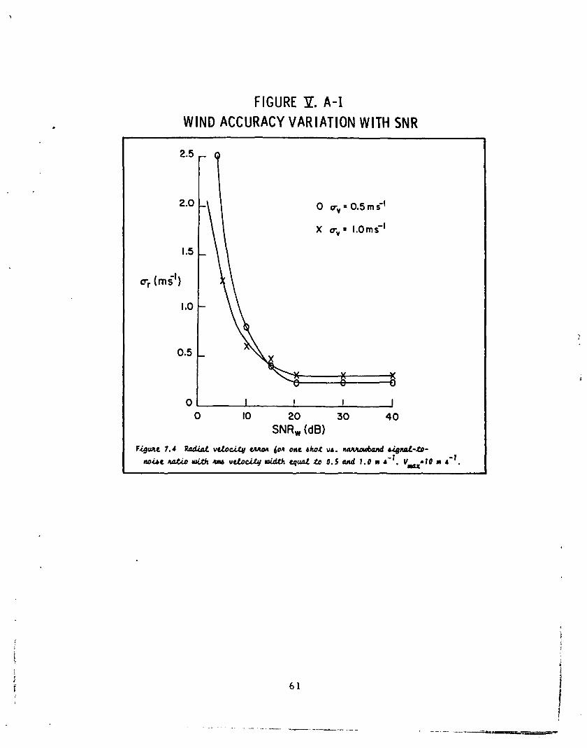
FIGURE '51. A-1 W I N D ACCURACY V A R I A T I O N W I T H SNR
2.5
2.0
1.5
q (mi ' )
IBO
0.5
0 ,
, Q
,
,
-
- V k w
I ! 1 I 0 10 20 30 40
SNRw (dB)
Figuec 7.4 Rndial v c t o c i ~ ~ l l ~ ~ n 60n one d h O t v ~ . n a w u h d rig&-@- m ~ r uti. w v b c i . t g l i d l k c p u t t. 0 . 5 mi 1 . 0 m 4.'. V--10 rn r-' .
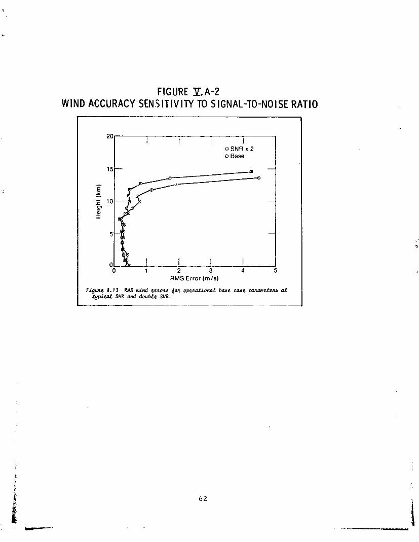
FIGURE Y . A - 2 WIND ACCURACY S E N S I T I V I N TO S IGNAL-TO-NOISE RATIO
A
20
IS
- E t i 10 cn Q, I
5
0 0 1 2 3 4 s
RMS Error (m/s)
Fqune 1 . 1 3 RMS L n d m u 604 o p W d b a e w e p a h ~ ~ e t ~ h d at Spical SNR and doubte SNR.
I
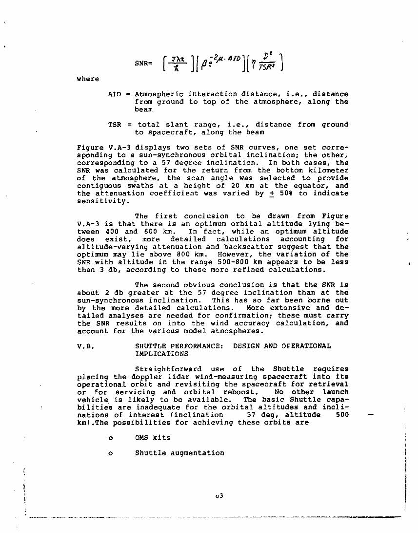
where
AID = Atmospheric interaction distance, i.e., distance from ground to top of the atmosphere, along the beam
TSR = total slant range, i.e., distance from ground to spacecraft, along the beam
Figure V.A-3 displays two sets of SNR curves, one set corre- sponding to a sun-synchronous orbital inclination; the other, corresponding to a 57 degree inclination. In both cases, the SNR was calculated for the return from the bottom kilometer of the atmosphere, the scan angle was selected to provide contiguous swaths at a height of 20 km at the equator, and the attenuation coefficient was varied by - + 50% to indicate sensitivity.
The first conclusion to be drawn from Figure V.A-3 is that there is an optimum orbital altitude lying be- tween 400 and 600 km. In fact, while an optimum altitude does exist, more detailed calculations accounting for altitude-varying attenuation and backscatter suggest that the optimum may lie above 800 km. However, the variation of the SNR with altitude in the range 500-800 km appears to be less than 3 db, according to these more refined calculations.
The second obvious conclusion is that the SNR is about 2 db greater at the 57 degree inclination than at the sun-synchronous inclination. This has so far been borne out by the more detailed calculations. More extensive and de- tailed analyses are needed for confirmation; these must carry the SNR results on into the wind accuracy calculation, and account for the various model atmospheres.
V. B. SHUTTLE PERFORMANCE: DESIGN AND OPERATIONAL IMPLICATIONS
Straightforward use of the Shuttle requires placing the doppler lidar wind-measuring spacecraft into its operational orbit and revisiting the spacecraft for retrieval or for servicing and orbital reboost. No other launch vehicle. is likely to be available. The basic Shuttle capa- bilities are inadequate for the orbital altitudes and incli- nations of interest (inclination 57 deg, altitude 500 km).The possibilities for achieving these orbits are
o OMS kits
o Shuttle augmentation
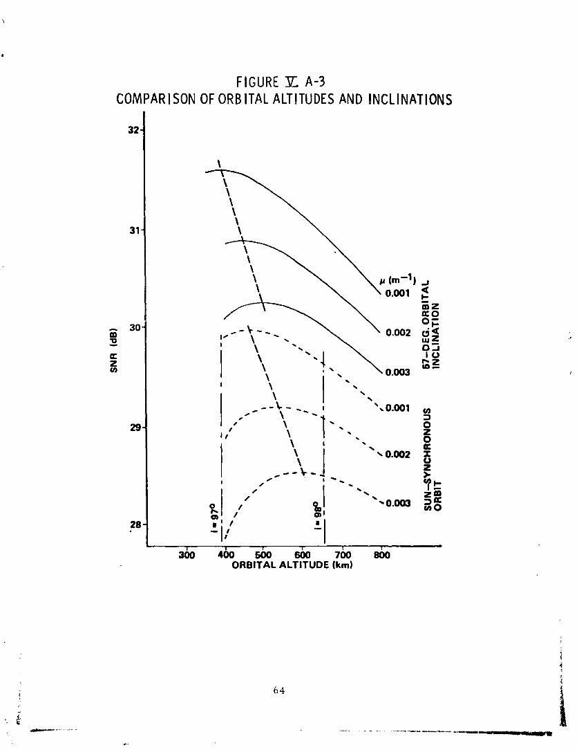
FIGURE % A-3 COMPARISON OF ORB ITAL ALTITUDES AND INCLINATIONS
L I I 1 I I 1
300 400 m 600 700 800 ORBITAL ALTITUDE tkm)
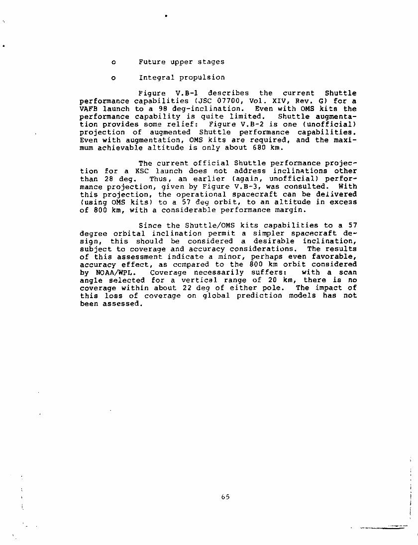
0 Future upper stages
o Integral propulsion
Figure V.B-1 describes the current Shuttle performance capabilities (JSC 07700, Vol. XIV, Rev. GI for a VAFB launch to a 98 deg-inclinatian. Even with OMS kits the performance capability is quite limited. Shuttle augmenta- tion provides some relief: Figure V.B-2 is one (unofficial) projection of augmented Shut.tle performance capabilities. Even with augmentation, OMS kits are required, and the maxi- mum achievable altitude is only about 680 km.
The current official Shuttle performance projec- tion for a KSC launch does not address inclinations other than 28 deg. Thus, an earlier (again, unofficial) perfor- mance projection, given by Figure V.B-3, was consulted. With this projection, the operational spacecraft can be delivered (using OMS kits) to a 57 deg orbit, to an altitude in excess of 800 km, with a considerable performance margin.
Since the Shuttle/OMS kits capabilities to a 57 degree orbital inclination permit a simpler spacecraft de- sign, this should be considered a desirahle inclination, subject to coverage and accuracy considerations. The results of this assessment indicate a minor, perhaps even favorable, accuracy effect, as ccmpared tc the 800 km orbit considered by NOAA/WPL. Coverage necessarily suffers: with a scan angle selected for a vertical range of 20 km, there is no coverage within about 22 deg of either pole. The impact of this loss of coverage on global prediction models has not been assessed.

FIG
URE
V.
B-l
NE
AR T
ERM
CAR
GO
WEI
GHT
VER
SUS
CIR
CU
LAR
O
RB IT
AL A
LTIT
UDE-
VAFB
LAU
NCH,
DEL
IVER
Y O
NLY
SH
UTT
LE P
ERFO
RM
ANC
E IS
A F
UN
CTI
ON
OF
PRO
GR
AM
VA
RIA
BLE
S (
LAU
NC
H D
ATE,
EN
GIN
E TH
RU
ST,,I
ND
IVID
UAL
O
RBI
TER
WEI
GH
T,
ETC
) AN
D M
US
T B
E D
ETE
RM
INE
D O
N A
CA
SE
BY
CA
SE
BA
SIS
CAR
GO
WE
IGH
T IN
CLU
DE
S A
LL
PA
YLO
AD
ITE
MS
AN
D
PA
YLO
AD
SU
PPO
RT
SE
RV
ICE
S
SHAD
ED A
RE
AS
RE
PR
ES
EN
T P
RIM
AR
Y R
EGIO
NS
AFF
EC
TED
BY
PR
OG
RAM
VA
RIA
BLE
S.
PA
YLO
AD
S
REQ
UIR
ING
PER
FOR
MAN
CE
IN T
HE
SE
REG
ION
S S
HO
ULD
V
ER
IFY
CA
PA
BIL
ITY
WIT
H J
SC A
S E
AR
LY A
S P
OS
SIB
LE
PO
TEN
TIA
L E
T D
ISP
OS
AL
PR
OB
LEM
S E
XIS
T FO
R I
NC
LIN
ATI
ON
S B
ELO
W 7
00
FIR
ST
OM
S K
IT
10
6
20
0
30
0
40
0
50
0
60
0
70
0
80
0
i
CIR
CU
LAR
OR
BIT
ALT
ITU
DE
, N
MI
I
I I
I I
I 2
00
4'0
0
60
0
80
0
10
00
1
20
0
CIR
CU
LAR
OR
BIT
AL
ALT
ITU
DE
, K
M
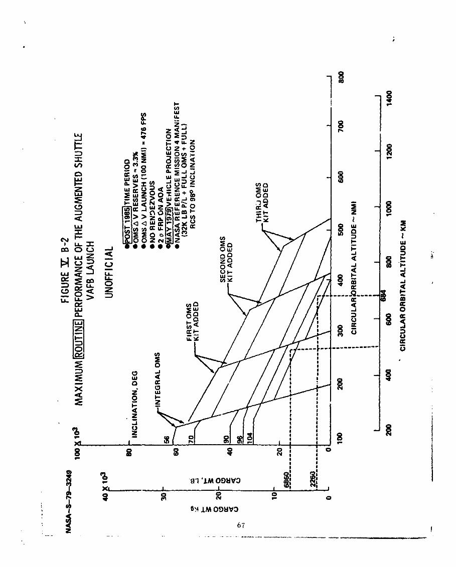
NA
SA
-S-7
9-49
FI
GUR
E P. B
-2
lw
F( '0
3
MA
XIM
UM
[-I PE
RFOR
MAN
CE O
F TH
E AU
GMEN
TED
SHUT
TLE
I VA
FB L
AUNC
H 40 x
1s
INC
LIN
AT
ION
, D
EG
UNO
FFIC
I AL .~~
O=~T
IME
PE
RIO
D
.OMS
A V
RE
SE
RV
ES
= 3.396
.OMS
A V
LA
UN
CH
(1Q
O N
MI)
= 4
76 F
PS
INT
EG
RA
L O
MS
.N
O
RE
N3E
zVO
US
a2 o
FR
PO
N A
OA
~
~]
vE
~~
~c
LE
P
RO
JEC
TIO
N
NA
SA
RE
FE
RE
NC
E M
lSS
lON
4 M
AN
iFE
ST
FIR
ST
OM
S
(32K
LB
P/L
+ F
UL
L O
MS
+ F
UL
L)
RC
S T
O 9
80 I
NC
LIN
AT
ION
I 1
.- I
i C
IRC
ULA
R O
RB
ITA
L A
LTIT
UD
E -
- K
M
FIG
URE
31.
0-3
NEAR
TER
M (P
RE 1
985)
CAR
GO
WEI
GHT
VER
SUS
C IR
CULA
R 08
0 IT
AL A
LTIT
UDE
lea x
lo3
KSC
LAUN
CH,
DELI
VERY
ONL
Y
I U
NO
FFIC
IAL
40 x
103
M
AX
IMU
M R
OU
TIN
E P
ER
FO
RM
AN
CE
E
ST:
19
82-8
5 T
IME
PE
RIO
D
OV
-99
BLO
CK
II
ET
F
UL
L R
CS
3
FU
LL
EP
ST
AN
KS
O
OM
S A
V R
ES
ER
VE
= 3.396
OM
S A
V L
AU
NC
H (T
O 1
00 N
MI.
CIR
C)
= 20
0 FP
S
INC
LIN
AT
ION
, D
EG
F
EB
79
VE
HIC
LE P
RO
JEC
TIO
N
NO
PE
ND
EZ
VO
US
S
TS R
ES
ER
VE
INC
LUD
ED
FIR
ST
OM
S K
IT A
DD
ED
SE
CO
ND
OM
S K
IT A
DD
ED
TH
IRD
OM
S K
IT A
DD
ED
I I
I 10
0 200
; 300
a;
500
600
700
I
I
CIR
CU
LAR
OR
BIT
AL
: A
LTIT
UD
E,
N.
MI.
:
I
I I
I
I #
1 I
1
200
430.
600
800
loo
0
1200
11
00
CIR
CU
LAR
OR
BIT
AL
ALT
ITU
DE
, K
M
APPROVAL
ACCOMMODAT I ONS ASSESSMENT :
SPACEBOJNE DOPPLER L IDAR
WIND PiEASURING SYSTEM
The i n f o r m a t i o n in th i s r e p o r t h a s been r e v i e w e d f o r s e c u r i t y c l a s s i f i c a t i o n . Rev iew of a n y i n f o r m a t i o n c o n c e r n i n g D e p a r t m e n t of Defense o r Atomic E n e r g y C o m m i s s i o n p r o g r a m s h a s b e e n made by t h e h l S F C S e c u r i t y C l a s s i f i c a t i o n Off ice r . T h i s r e p o r t , in i t s e n t i r e t y , h a s been d e t e r m i n e d t o be unc lass i f i ed .
Th is document h a s a l s o t ~ e e n rev iewed and a p p r o v e d f o r t e c h n i - c a l a c c u r a c y .
CHARLES R . DARWIN D i r e c t o r , Preliminary Des ign Oif ice
b~ Qb'm -- L-??~-.
WILLIAM R. MARSHALL D i r e c t o r , P r o g r a m Deve lopment