Embed Size (px)
Citation preview
NASA TECHNICAL
MEMORANDUM
LTlCOCOI
X
NASA TM X-3359
wo
MODEL FOR CALCULATING ELECTROLYTIC
SHUNT PATH LOSSES IN LARGE
ELECTROCHEMICAL ENERGY
CONVERSION SYSTEMS
Paul R. Prokopius
Lewis Research Center
Cleveland, Ohio 44135
NATIONAL AERONAUTICS AND SPACE ADMINISTRATION • WASHINGTON, D. C. • APRIL 1976
https://ntrs.nasa.gov/search.jsp?R=19760014614 2020-03-21T09:05:13+00:00Z
1, Report No.
NASA TMX-33592. Government Accession No. 3. Recipient's Catalog No.
4. Title and Subtitle
MODEL FOR CALCULATING ELECTROLYTIC SHUNTPATH LOSSES IN LARGE ELECTROCHEMICALENERGY CONVERSION SYSTEMS
5. Report Date
April 19766. Performing Organization Code
7. Author(s)
Paul R. Prokopius8. Performing Organization Report No.
E-8501
9. Performing Organization Name and Address
Lewis Research CenterNational Aeronautics and Space AdministrationCleveland, Ohio 44135
10. Work Unit No.
506-2311. Contract or Grant No.
12. Sponsoring Agency Name and Address
National Aeronautics and Space AdministrationWashington, D. C. 20546
13. Type of Report and Period Covered
Technical Memorandum14. Sponsoring Agency Code
15. Supplementary Notes
16. Abstract
Generalized analysis and solution techniques were developed to evaluate the shunt power lossesin electrochemical systems designed with a common or circulating electrolyte supply. Sampledata are presented for a hypothetical bulk energy storage redox system, and the general appli-cability of the analysis technique is discussed.
17. Key Words (Suggested by Author(s))
Electrochemical energy conversionElectrolytic shunt currentsCircuit analogComputerized solution technique
18. Distribution Statement
Unclassified - unlimitedSTAR Category 44
19. Security Classif. (of this report)
Unclassified20. Security Classif. (of this pagel
Unclassified21. No. of Pages
1322. Price"
$3.25
For sale by the National Technical Information Service, Springfield. Virginia 22161
MODEL FOR CALCULATING ELECTROLYTIC SHUNT PATH LOSSES IN
LARGE ELECTROCHEMICAL ENERGY CONVERSION SYSTEMS
by Paul R. Prokopius
Lewis Research Center
SUMMARY
The quest for efficient energy conversion techniques may bring about the commer-cialization of electrochemical energy storage and generation systems. Within this gen-eral classification some of the systems may be designed with a common or circulatingelectrolyte supply. In such systems one of the factors that must be accounted for in thedesign is the power loss or self-discharge by cell to cell ionic shunt currents. Thisstudy addresses this design facet, the objective being to develop a mathematical analysisand solution technique to evaluate the shunt power losses in large electrochemical sys-tems.
Analytical tools consisting of an electrical shunt current circuit analog and a com-puterized solution technique were devised. This analytical work was done on the redoxflow cell, but it is generally applicable in modified form to other systems. Representa-tive data are presented for a sample redox system, and the applicability of this analysistechnique to other systems such as fuel cells or fluid flow networks is discussed.
INTRODUCTION
A design concept of many electrochemical energy conversion systems is to use acirculating or common electrolyte supply. Representative systems past and present inwhich this concept is employed are as follows:
(1) Hydrazine - hydrogen peroxide fuel cells (Alsthom Company)(2) Low temperature alkaline fuel cell (Union Carbide)(3) Lithium - seawater battery (Lockheed Company)(4) Bulk energy storage redox (NASA-Lewis Research Center)The reasons for designing a system with a circulating electrolyte are varied. These
include using the flowing electrolyte stream for a reactant delivery system as in the hy-drazine fuel cells and redox flow cells, a heat and water removal medium as in the
alkaline cells, or a reactant control parameter as in the lithium-seawater battery.Though the individual design reasons vary, a parameter common to all systems whichemploy a circulating electrolyte is the power loss or self-discharge through cell to cellionic shunt currents.
This shunt loss characteristic needs to be considered in any system design; how-ever, most cases in the past did not require an indepth analysis. A common approachwas to extrapolate basic shunt loss calculations to the size of the systems under consid-eration. In the simplest sense this extrapolation was made from single shunt loop losscalculations or from small stack analyses. For the most part, this type of analysis wassufficient for the low voltage systems (i. e., low shunt current driving voltage) built forunique applications - space, underwater, etc. In this type of system, while operatingefficiency is an important consideration, design emphasis is placed on system reliability.This is not the case, however, for large terrestrial systems such as bulk storage redox.In this class of systems, design emphasis is placed on conversion efficiency as well asreliability; consequently, the shunt loss characteristic becomes more significant in thesystem design.
With this background, a study was conducted to develop generalized shunt power lossanalyses and solution techniques. An electrical circuit was proposed as an analog model,and a computer program was written with which to do the shunt loss calculations. Thecomputer program was generalized in the sense that by making minor program inputmodifications virtually any size or type of electrochemical system can be analyzed.
SHUNT CURRENT MODEL DEVELOPMENT
Redox Concept
A redox couple is characterized by a pair of oxidation-reduction reactions in whichthe ions of the couple remain soluble in their electrolytes in both the reduced and oxi-dized state. The rechargeable redox flow cell scheme is based on pumping two redoxcouple solutions through a power conversion unit to alternately charge and discharge thereactant solutions. In a utility bulk storage application the power conversion unit wouldbe coupled with the power network such that the reactant solutions could be charged tostore excess off-peak power and discharged to supply the peak power demand. A de-tailed description of the redox flow cell concept is presented in reference 1.
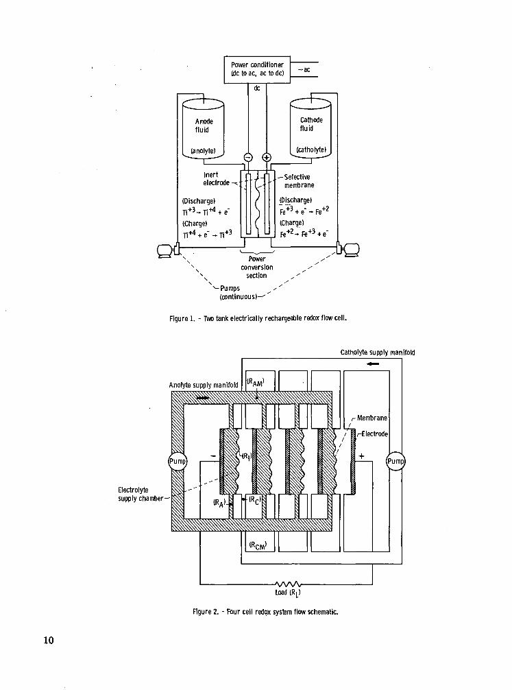
A general schematic of a two-tank bulk energy storage redox system is shown infigure 1. The main components of this system are the catholyte and anolyte storagetanks, reactant circulating pumps, power conversion unit, and ac to dc and dc to acpower conditioning equipment. The couples chosen for illustration are titaniumtrichloride/titanium tetrachloride and ferrous/ferric chloride. Their respective
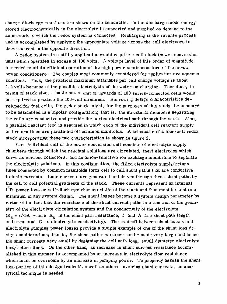
charge-discharge reactions are shown on the schematic. In the discharge mode energystored electrochemically in the electrolyte is converted and supplied on demand to theac network to which the redox system is connected. Recharging is the reverse processand is accomplished by applying the appropriate voltage across the cell electrodes todrive current in the opposite direction.
A redox system in a utility application would require a cell stack (power conversionunit) which operates in excess of 100 volts. A voltage level of this order of magnitudeis needed to attain efficient operation of the high power semiconductors of the ac-dcpower conditioners. The couples most commonly considered for application are aqueoussolutions. Thus, the practical maximum attainable per cell charge voltage is about1. 2 volts because of the possible electrolysis of the water on charging. Therefore, interms of stack size, a basic power unit of upwards of 100 series-connected cells wouldbe required to produce the 100-volt minimum. Borrowing design characteristics'de-veloped for fuel cells, the redox stack might, for the purposes of this study, be assumedto be assembled in a bipolar configuration; that is, the structural members separatingthe cells are conductive and provide the series electrical path through the stack. Also,a parallel reactant feed is assumed in which each of the individual cell reactant supplyand return lines are paralleled off common manifolds. A schematic of a four-cell redoxstack incorporating these two characteristics is shown in figure 2.
Each individual cell of the power conversion unit consists of electrolyte supplychambers through which the reactant solutions are circulated, inert electrodes whichserve as current collectors, and an anion-selective ion exchange membrane to separatethe electrolytic solutions. In this configuration, the filled electrolyte supply/returnlines connected by common manifolds form cell to cell shunt paths that are conductiveto ionic currents. Ionic currents are generated and driven through these shunt paths bythe cell to cell potential gradients of the stack. These currents represent an internalo
I R power loss or self-discharge characteristic of the stack and thus must be kept to aminimum in any system design. The shunt losses become a system design parameter byvirtue of the fact that the resistance of the shunt current paths is a function of the geom-etry of the electrolyte circulation system and the conductivity of the electrolyte(R., = l/GA where R_ is the shunt path resistance, I and A are shunt path length
O O
and area, and G is electrolytic conductivity). The tradeoff between shunt losses andelectrolyte pumping power losses provide a simple example of one of the shunt loss de-sign considerations; that is, the shunt path resistance can be made very large and hencethe shunt currents very small by designing the cell with long, small diameter electrolytefeed/return lines. On the other hand, an increase in shunt current resistance accom-plished in this manner is accompanied by an increase in electrolyte flow resistancewhich must be overcome by an increase in pumping power. To properly assess the shuntloss portion of this design tradeoff as well as others involving shunt currents, an ana-lytical technique is needed.
Circuit Analog
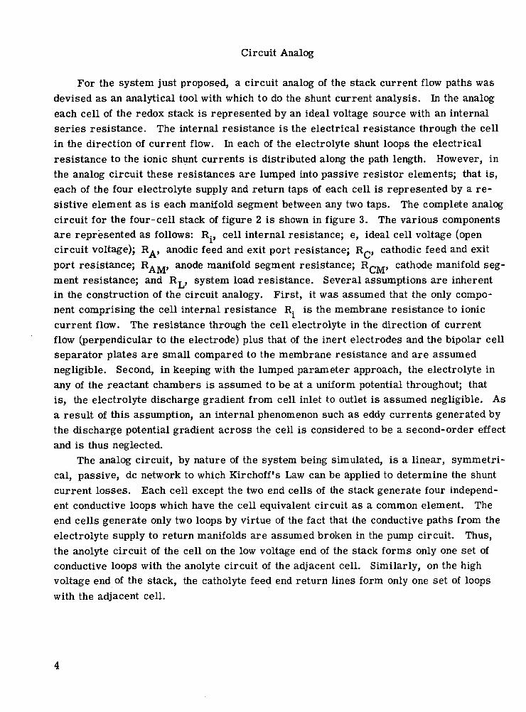
For the system just proposed, a circuit analog of the stack current flow paths wasdevised as an analytical tool with which to do the shunt current analysis. In the analogeach cell of the redox stack is represented by an ideal voltage source with an internalseries resistance. The internal resistance is the electrical resistance through the cellin the direction of current flow. In each of the electrolyte shunt loops the electricalresistance to the ionic shunt currents is distributed along the path length. However, inthe analog circuit these resistances are lumped into passive resistor elements; that is,each of the four electrolyte supply and return taps of each cell is represented by a re-sistive element as is each manifold segment between any two taps. The complete analogcircuit for the four-cell stack of figure 2 is shown in figure 3. The various componentsare represented as follows: R., cell internal resistance; e, ideal cell voltage (opencircuit voltage); R., anodic feed and exit port resistance; Rp, cathodic feed and exitport resistance; R^M, anode manifold segment resistance; RrM, cathode manifold seg-ment resistance; and Ry, system load resistance. Several assumptions are inherentin the construction of the circuit analogy. First, it was assumed that the only compo-nent comprising the cell internal resistance R. is the membrane resistance to ioniccurrent flow. The resistance through the cell electrolyte in the direction of currentflow (perpendicular to the electrode) plus that of the inert electrodes and the bipolar cellseparator plates are small compared to the membrane resistance and are assumednegligible. Second, in keeping with the lumped parameter approach, the electrolyte inany of the reactant chambers is assumed to be at a uniform potential throughout; thatis, the electrolyte discharge gradient from cell inlet to outlet is assumed negligible. Asa result of this assumption, an internal phenomenon such as eddy currents generated bythe discharge potential gradient across the cell is considered to be a second-order effectand is thus neglected.
The analog circuit, by nature of the system being simulated, is a linear, symmetri-cal, passive, dc network to which Kirchoff's Law can be applied to determine the shuntcurrent losses. Each cell except the two end cells of the stack generate four independ-ent conductive loops which have the cell equivalent circuit as a common element. Theend cells generate only two loops by virtue of the fact that the conductive paths from theelectrolyte supply to return manifolds are assumed broken in the pump circuit. Thus,the anolyte circuit of the cell on the low voltage end of the stack forms only one set ofconductive loops with the anolyte circuit of the adjacent cell. Similarly, on the highvoltage end of the stack, the catholyte feed end return lines form only one set of loopswith the adjacent cell.
MODEL ANALYSIS
As stated previously, the shunt path analog circuit can be analyzed using Kirchoff'sLaw. The currents shown on the circuit diagram of figure 3 are the Kirchoff loop cur-rents for the 13 independent loops of the four-cell stack. The currents i< to ij«,represent the shunt loop currents and i-, the loop current for the load circuit. In thisnetwork, clockwise current flow was designated as the positive current direction.Equating the sum of the IR voltage drops around each of the Kirchoff loops to the volt-age rise across the cell ideal source generates the voltage drop equations for the 13 in-dependent loops. These result in a set of 13 simultaneous algebraic equations to besolved for the 13 unknown loop currents. The loop currents thus identify the currentsflowing through the various elements of the electrolytic leakage paths. In some in-stances the loop current itself defines a leakage or shunt current factor. This occurswhenever the component in question is not in common with any other loop. The currentswhich are not determined directly are defined by a difference in loop currents such asUo - ig) which defines the leakage current flowing in the anolyte feed line to cell two.The leakage current through each individual resistive component is needed to calculatethe power loss in each component. The individual component power losses can then besummed to determine the total shunt current power loss of the stack.
For a redox stack of N cells with the stack configuration shown in figure 2, the ex-pression 4(N-1)+1 defines the number of Kirchoff loop equations in the circuit analogy.From this it is obvious that for any commercial sized stack, which would undoubtedlyinvolve hundreds of equations, a computerized analysis is necessary.
Of the many direct, iterative, or statistical methods of solving systems of linearequations, Grout's method appears to be well suited to this application in terms of com-putational and computer storage efficiency. In this method a matrix is constructed usingthe coefficients and independent variables of the Kirchoff equations. This coefficientmatrix is manipulated on a term by term basis to obtain a derived matrix from which theequations' solutions can be obtained. The manipulation is such that as the various termsare being determined for the derived matrix, the terms of the original coefficient matrixneed not be retained. Thus, only one matrix array need be allocated in the computerstorage system. Also, because of the symmetry of the circuit being analyzed and thelimited degree of commonality from loop to loop, the resultant equation matrix is largelysymmetrical with only a few nonzero terms on either side of the major diagonal. Again,Grout's method lends itself well in taking advantage of this symmetry and the largeblocks of zero terms. The resultant effect is that a very large number of simultaneousequations can be handled with a very small array.
The mechanics of the computational method may be best explained by an example.Given are three equations in the three unknowns, x.,, Xg, x«:
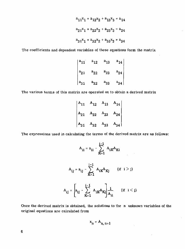
allxl + a!2x2 + a!3x3 ~ a!4
a21xl + a22x2 + a23x3 = a24
a31Xl + a32x2 + a33x3 = a34
The coefficients and dependent variables of these equations form the matrix
a!2 a!3 a!4
22 a23 a24
a31 a32 a33 a34
The various terms of this matrix are operated on to obtain a derived matrix
A12 A13 A14
A21 A22 A23 A24
A31 A32 A33 A34
The expressions used in calculating the terms of the derived matrix are as follows:
AiKAKiK=l
EK=l
A
K=liKAKj — (if i
Once the derived matrix is obtained, the solutions to the n unknown variables of theoriginal equations are calculated from
xn ~ An,
n
" Li AiKxKK=i+l
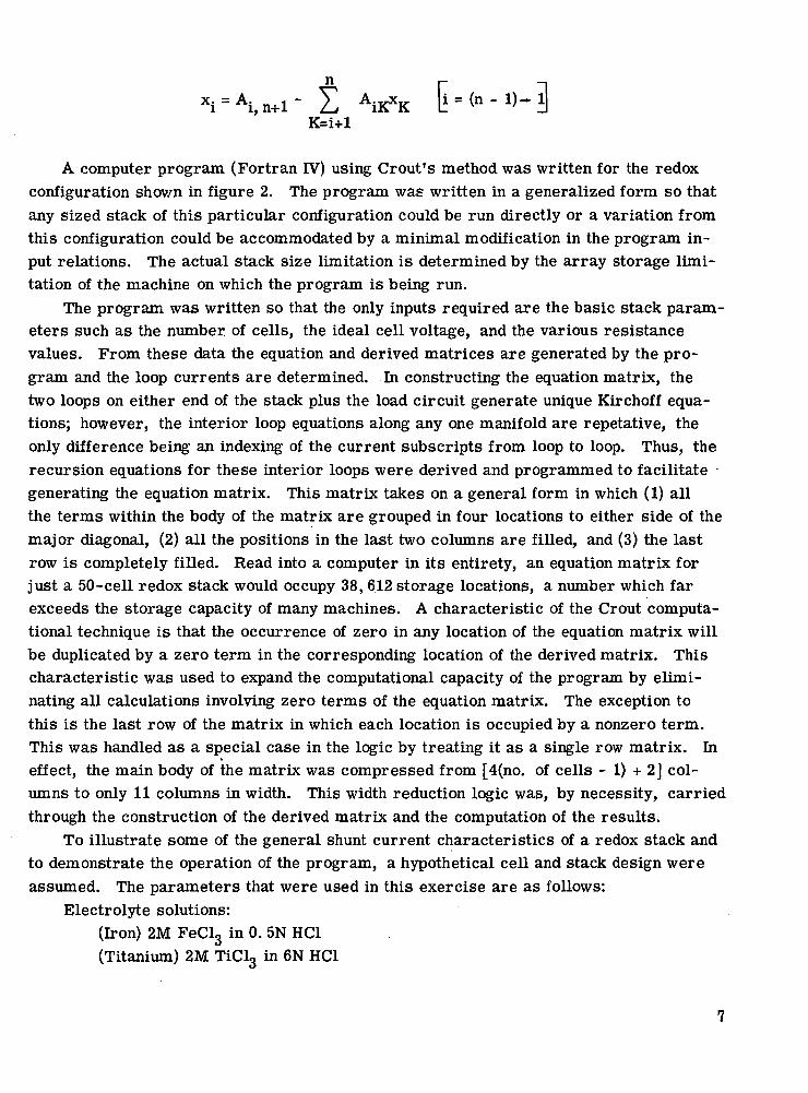
A computer program (Fortran IV) using Grout's method was written for the redoxconfiguration shown in figure 2. The program was written in a generalized form so thatany sized stack of this particular configuration could be run directly or a variation fromthis configuration could be accommodated by a minimal modification in the program in-put relations. The actual stack size limitation is determined by the array storage limi-tation of the machine on which the program is being run.
The program was written so that the only inputs required are the basic stack param-eters such as the number, of cells, the ideal cell voltage, and the various resistancevalues. From these data the equation and derived matrices are generated by the pro-gram and the loop currents are determined. In constructing the equation matrix, thetwo loops on either end of the stack plus the load circuit generate unique Kirchoff equa-tions; however, the interior loop equations along any one manifold are repetative, theonly difference being an indexing of the current subscripts from loop to loop. Thus, therecursion equations for these interior loops were derived and programmed to facilitategenerating the equation matrix. This matrix takes on a general form in which (1) allthe terms within the body of the matrix are grouped in four locations to either side of themajor diagonal, (2) all the positions in the last two columns are filled, and (3) the lastrow is completely filled. Read into a computer in its entirety, an equation matrix forjust a 50-cell redox stack would occupy 38, 612 storage locations, a number which farexceeds the storage capacity of many machines. A characteristic of the Grout computa-tional technique is that the occurrence of zero in any location of the equation matrix willbe duplicated by a zero term in the corresponding location of the derived matrix. Thischaracteristic was used to expand the computational capacity of the program by elimi-nating all calculations involving zero terms of the equation matrix. The exception tothis is the last row of the matrix in which each location is occupied by a nonzero term.This was handled as a special case in the logic by treating it as a single row matrix. Ineffect, the main body of the matrix was compressed from [4(no. of cells - 1) + 2] col-umns to only 11 columns in width. This width reduction logic was, by necessity, carriedthrough the construction of the derived matrix and the computation of the results.
To illustrate some of the general shunt current characteristics of a redox stack andto demonstrate the operation of the program, a hypothetical cell and stack design wereassumed. The parameters that were used in this exercise are as follows:
Electrolyte solutions:(Iron) 2M FeClg in 0. 5N HC1(Titanium) 2M TiCL, in 6N HC1
Cell and stack geometry:oActive cell area, 2 ft
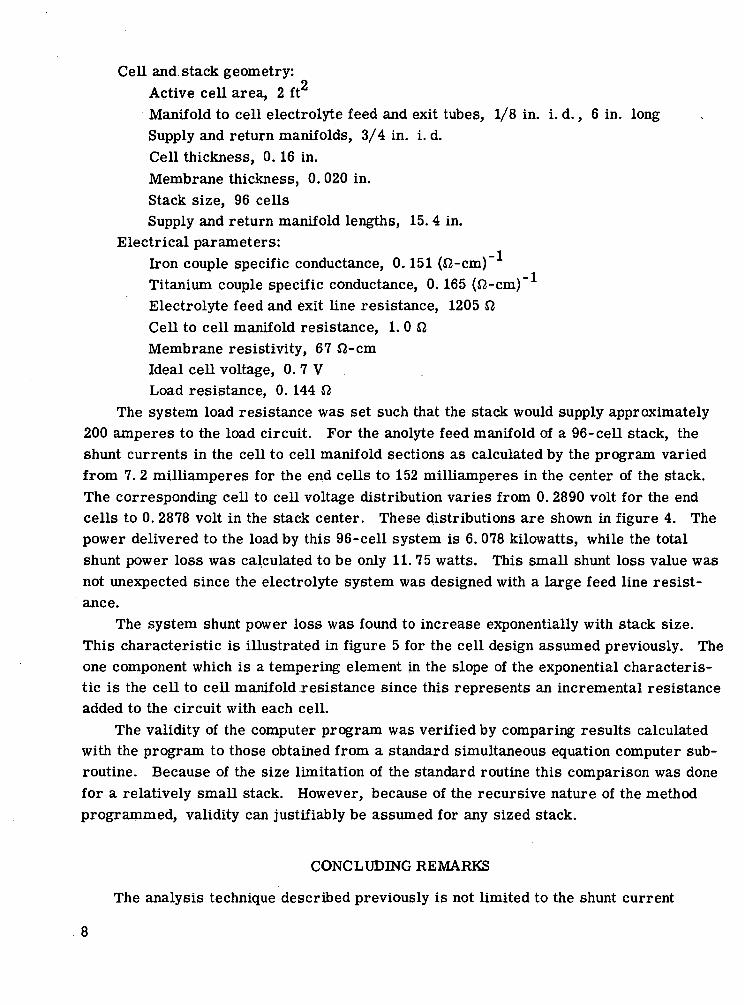
Manifold to cell electrolyte feed and exit tubes, 1/8 in. i. d., 6 in. longSupply and return manifolds, 3/4 in. i. d.Cell thickness, 0.16 in.Membrane thickness, 0. 020 in.Stack size, 96 cellsSupply and return manifold lengths, 15.4 in.
Electrical parameters:Iron couple specific conductance, 0.151 (fi-cm)~Titanium couple specific conductance, 0.165 (£2-cm)~Electrolyte feed and exit line resistance, 1205 OCell to cell manifold resistance, 1. 0 fiMembrane resistivity, 67 J2-cmIdeal cell voltage, 0. 7 VLoad resistance, 0. 144 fi
The system load resistance was set such that the stack would supply approximately200 amperes to the load circuit. For the anolyte feed manifold of a 96-cell stack, theshunt currents in the cell to cell manifold sections as calculated by the program variedfrom 7. 2 milliamperes for the end cells to 152 milliamperes in the center of the stack.The corresponding cell to cell voltage distribution varies from 0. 2890 volt for the endcells to 0. 2878 volt in the stack center. These distributions are shown in figure 4. Thepower delivered to the load by this 96-cell system is 6.078 kilowatts, while the totalshunt power loss was calculated to be only 11. 75 watts. This small shunt loss value wasnot unexpected since the electrolyte system was designed with a large feed line resist-ance.
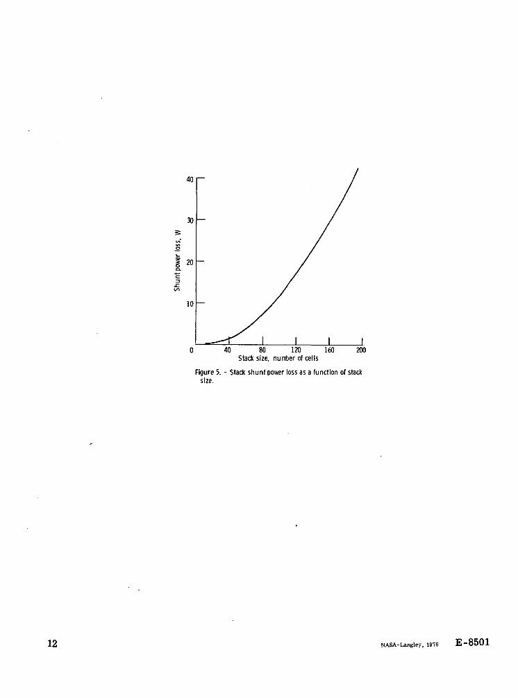
The system shunt power loss was found to increase exponentially with stack size.This characteristic is illustrated in figure 5 for the cell design assumed previously. Theone component which is a tempering element in the slope of the exponential characteris-tic is the cell to cell manifold resistance since this represents an incremental resistanceadded to the circuit with each cell.
The validity of the computer program was verified by comparing results calculatedwith the program to those obtained from a standard simultaneous equation computer sub-routine. Because of the size limitation of the standard routine this comparison was donefor a relatively small stack. However, because of the recursive nature of the methodprogrammed, validity can justifiably be assumed for any sized stack.
CONCLUDING REMARKS
The analysis technique described previously is not limited to the shunt current
8
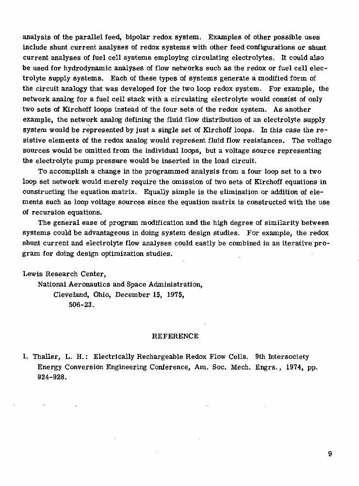
analysis of the parallel feed, bipolar redox system. Examples of other possible usesinclude shunt current analyses of redox systems with other feed configurations or shuntcurrent analyses of fuel cell systems employing circulating electrolytes. It could alsobe used for hydrodynamic analyses of flow networks such as the redox or fuel cell elec-trolyte supply systems. Each of these types of systems generate a modified form ofthe circuit analogy that was developed for the two loop redox system. For example, thenetwork analog for a fuel cell stack with a circulating electrolyte would consist of onlytwo sets of Kirchoff loops instead of the four sets of the redox system. As anotherexample, the network analog defining the fluid flow distribution of an electrolyte supply
\
system would be represented by just a single set of Kirchoff loops. In this case the re-sistive elements of the redox analog would represent fluid flow resistances. The voltagesources would be omitted from the individual loops, but a voltage source representingthe electrolyte pump pressure would be inserted in the load circuit.
To accomplish a change in the programmed analysis from a four loop set to a twoloop set network would merely require the omission of two sets of Kirchoff equations inconstructing the equation matrix. Equally simple is the elimination or addition of ele-ments such as loop voltage sources since the equation matrix is constructed with the useof recursion equations.
The general ease of program modification and the high degree of similarity betweensystems could be advantageous in doing system design studies. For example, the redoxshunt current and electrolyte flow analyses could easily be combined in an iterative pro-gram for doing design optimization studies.
Lewis Research Center,National Aeronautics and Space Administration,
Cleveland, Ohio, December 15, 1975,506-23.
REFERENCE
1. Thaller, L. H.: Electrically Rechargeable Redox Flow Cells. 9th IntersocietyEnergy Conversion Engineering Conference, Am. Soc. Mech. Engrs., 1974, pp.924-928.
Anodefluid
(anolyte)
Power conditioner(dc to ac, ac to dc)
dc
~ac
x— FCathodfluid
(catholy
Inertelectrode -*]-•
(Discharge)
(Charge)
^Selectivemembrane
(Discharge)
(Charge)
Fe+2-Fe+3+e"
Powerconversion
section
to^ Pumps ^x
(continuous)—x
Figure 1. - Two tank electrically rechargeable redox flow cell.
Catholyte supply manifold
Anolyte supply manifold
Electrolytesupply chamber—
A/WVLoad (RL>
Figure 2. - Four cell redpx system flow schematic.
10
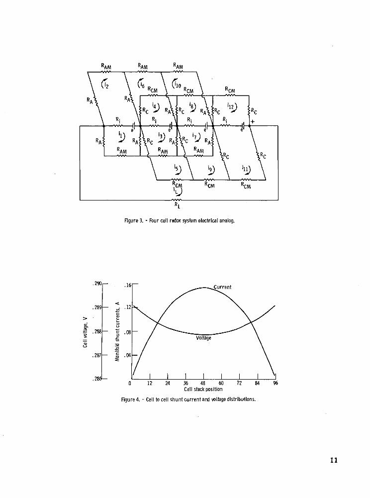
Figure 3. - Four cell redox system electrical analog.
.290,—
.289
en5 .2881—
- ..- .12
8.287 —
.2861—
Current
36 48 60Cell stack position
Figured - Cell to cell shunt current and voltage distributions.
11
401—
40 80 120 160Stack size, number of cells
200
Figure 5. - Stack shunt power loss as a function of stacksize.
12 NASA-Langley, 1976 E-8501