Embed Size (px)
Citation preview
NASA TECHNICAL NOTE
wo
"ASA TN D-7260
ANALYSIS OF HEAT TRANSFERFOR A NORMALLY IMPINGINGLIQUID-METAL SLOT JET
by Robert Siegel
Lewis "Research Center
Cleveland) Ohio 44135
NATIONAL A E R O N A U T I C S AND SPACE ADMINISTRATION • WASHINGTON, D. C. • APRIL 1973
https://ntrs.nasa.gov/search.jsp?R=19730012211 2018-07-26T22:57:43+00:00Z
1. Report No. 2. Government Accession No.
NASA TN D-7260
4. Title and Subtitle
ANALYSIS OF HEAT TRANSFER FOR A NORMALLY
IMPINGING LIQUID-METAL SLOT JET
7. Author(s)
Robert Siegel
9. Performing Organization Name and Address
Lewis Research Center
National Aeronautics and Space Administration
Cleveland, Ohio 44135
12. Sponsoring Agency Name and Address
National Aeronautics and Space Administration
Washington, D. C. 20546
3. Recipient's Catalog No.
5. Report Date
April 1973
6. Performing Organization Code
8. Performing Organization Report No.
E-7222
10. Work Unit No.
501-24
11. Contract or Grant No.
13. Type of Report and Period Covered
Technical Note
14. Sponsoring Agency Code
15. Supplementary Notes
16. Abstract
The analysis treats a two-dimensional liquid-metal slot jet that is impinging normally againsta uniformly heated flat plate. The distributions of wall temperature and heat-transfer coeffi-cient are obtained as functions of position along the plate. The liquid-metal assumptions aremade that the jet is inviscid and that molecular conduction is dominating heat diffusion. Thesolution is obtained by mapping the jet flow region into a potential plane where it occupies astrip of uniform width. The energy equation is transformed into potential coordinates, and anexact solution obtained in the strip region. Conformal mapping is then used to transform thesolution into the physical plane.
17. Key Words (Suggested by Author(sl)
Impingement heat transfer; JetJet impingement; Liquid-metalLiquid- metal jet
19. Security dassif. (of this report)
Unclassified
heat transfer;heat transfer;
18. Distribution Statement
Unclassified - unlimited
20. Security Classif. (of this page) 21 . No. o
Unclassified 32f Pages 22. Price*
$3.00
* For sale by the National Technical Information Service, Springfield, Virginia 22151

ANALYSIS OF HEAT TRANSFER FOR A NORMALLY
IMPINGING LIQUID-METAL SLOT JET
by Robert Siegel
Lewis Research Center
SUMMARY
Liquid metals are very effective heat-transfer fluids. For critical local coolingapplications a useful technique may be to use an impinging liquid-metal jet. In thisreport a two-dimensional analysis is performed for a liquid-metal slot jet impingingnormally against a flat plate that is heated uniformly. Wall temperatures and heat-transfer coefficients are obtained as functions of position along the plate for variousvalues of the Peclet number. Liquid metals are low Prandtl number fluids, and as aconsequence a thermal boundary layer will develop much more rapidly than a viscouslayer. The fluid can then be approximated as inviscid because the viscous layer is ofminor importance in the thermal-boundary-layer growth. It is also assumed that turbu-lence is small so that molecular conduction is dominating the diffusion of heat. Thesolution is obtained by mapping the jet flow region into a potential plane in which the re-gion occupies a strip of uniform width. The energy equation is transformed into poten-tial coordinates, and an exact solution is obtained in the strip region. Conformalmapping is then used to transform the solution into the physical plane to yield the tem-perature distribution along the impingement plate.
INTRODUCTION
A possible technique for localized cooling is to use a jet impinging against the heat-transfer surface. Liquid metals are very effective heat-transfer fluids and hence mayprove useful in critical cooling applications.
For a liquid metal the molecular diffusion of heat is much larger than the moleculardiffusion of momentum (low Prandtl number fluid), and hence for developing flow andheat transfer the viscous boundary layers are much thinner than the thermal boundarylayers. As a result, the assumption is often made that the viscous-layer development
can be neglected in computing the heat transfer. The velocity field within the jet regioncan then be determined by using the techniques of inviscid free jet theory. For a two-dimensional situation in Cartesian coordinates the free streamlines can be found by con-formal mapping (refs. 1 and 2). For an axisymmetric jet, numerical techniques areused (refs. 3 and 4). The present study is limited to two dimensions in Cartesian coor-dinates (a slot jet) so that an analytical solution can be found.
In the conformal mapping solution the two-dimensional jet flow region is mappedinto a potential plane where it occupies a simple region, namely, a strip of constantheight and infinite length. The convective energy equation and boundary conditions canbe transformed into potential coordinates and in this coordinate system can be solved byavailable analytical techniques. This coordinate transformation of the energy equationhas been used to determine the heat transfer for bodies in crossflow (ref. 5). The pres-ent analysis is a combination of the inviscid free jet analysis and the energy equationtransformation technique. In the present problem these techniques reduce the analysisto obtaining the temperature distribution in a slab of uniform thickness moving acrossa plane of distributed heat sources. The solution can be found by generalizing a casetreated in reference 6.
Results are obtained for the wall temperature and heat-transfer coefficient along theimpingement plate for various values of the Peclet number. Simple approximate rela-tions are obtained at the stagnation point. The stagnation results are compared withthose in reference 7, which treats gases and ordinary liquids by use of a boundary-layer type of analysis.
SYMBOLS
b half-width of undisturbed jet
C specific heat of fluid
h local heat-transfer coefficient along plate
K modified Bessel function of second kind of order n
k thermal conductivity of fluid
m integer
Nu Nusselt number, h2b/k
Pe Peclet number, | v^ 12b/a
Pr Prandtl number, C u/k
q... heat flux specified at wall\V
Re jet Reynolds number, v
T dimensionless temperature, tk/bqw
t temperature
U dimensionless velocity in x direction, u/|vc
U dimensionless fluid velocity vector, u/Jv^ |
u fluid velocity vector
u, v velocities in x and y directions
X, Y dimensionless coordinates, x/b and y/b
x, y rectangular coordinates along and normal to plate
a thermal diffusivity, k/pC
F gamma function
77 dummy variable of integration
H fluid viscosity
v fluid kinematic viscosity, p./p
| coordinate normal to $ - * plane
p fluid density
$ dimensionless potential, ^ / I v ^ j b
<f> potential function
* dimensionless stream function, J^/lv^ |b
fy stream function
Subscripts:
w at wall00 undisturbed fluid condition
ANALYSIS
Geometry
The two-dimensional flow configuration is shown in figure 1. A slot jet with an un-disturbed width 2b impinges normally against a flat plate at y = 0. The plate has a
uniform heat flux q,IT supplied along it. After turning, the flow moves out in the posi-\V
tive and negative x directions in a symmetric fashion and for the inviscid-irrotationalsituation considered here reaches an asymptotic thickness b. From symmetry, onlythe first quadrant of the flow need be considered. In figure 1 some of the boundarypoints have been numbered 1 to 5 for convenience in identification.
Governing Equations
The fluid considered in this report is a liquid metal, and since liquid metals havevery low Prandtl numbers, the viscous diffusion is small compared with the moleculardiffusion of heat. Hence, in a flow where both the viscous and thermal boundary layersare developing simultaneously, there will be little diffusion of vorticity into the thermal-boundary-layer region. The viscous layer will be relatively thin, and the thermal layerwill be essentially all in the inviscid region. A flow that is initially irrotational willdevelop little vorticity and hence can be assumed to remain irrotational. It is alsoassumed that the jet Reynolds number is low enough so that turbulent heat diffusion isnot important in comparison with the molecular diffusion of heat, which is large for aliquid metal. These are standard assumptions for liquid-metal heat-transfer analysesin the low Reynolds number range (RePr < 50 in a tube or <500 for crossflow over tubebundles), as discussed in reference 8, page 300.
With these assumptions the fluid velocity can be obtained as the gradient of a poten-tial
u = V</> (1)
where <p is governed by Laplace's equation,
V2^ = 0 (2)
The Cauchy-Riemann equations apply so that the velocity components are related to thestream function by
(3a)9x dy
(3b)dy 9x
where the stream function also satisfies Laplace's equation,
=0 (4)
The energy equation for the flow is given by
or, when equation (1) is used, by
pCpu • Vt = kV2t
PC V(p • Vt = kV*t
(5)
(6)
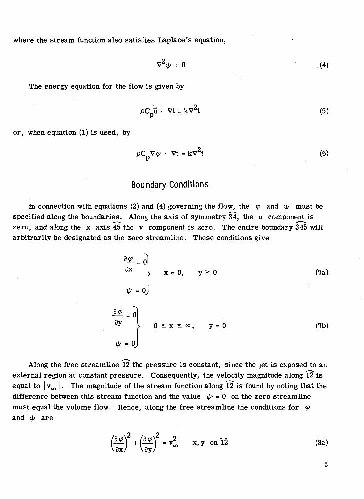
Boundary Conditions
In connection with equations (2) and (4) governing the flow, the <p and i// must bespecified along the boundaries. Along the axis of symmetry 34, the u component iszero, and along the x axis 45 the v component is zero. The entire boundary 345 willarbitrarily be designated as the zero streamline. These conditions give
ax x = 0, y a 0 (7a)
= <
0 < x < y = 0 (7b)
Along the free streamline 12 the pressure is constant, since the jet is exposed to anexternal region at constant pressure. Consequently, the velocity magnitude along ^ isequal to | v^ |. The magnitude of the stream function along 12 is found by noting that thedifference between this stream function and the value i//- = 0 on the zero streamlinemust equal the volume flow. Hence, along the free streamline the conditions for <pand ;// are
ay/x, y on 12 (8a)
5
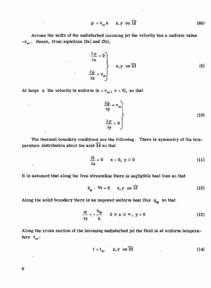
= vb x,y on 12 (8b)
Across the width of the undisturbed incoming jet the velocity has a uniform valuef^. Hence, from equations (3a) and (3b)(
3x
3x
> x, y on 23 (9)
At large x the velocity is uniform (u = v , v = 0), so that
(10)
The thermal boundary conditions are the following. There is symmetry of the tem-perature distribution about the axis 34 so that
— - 0 x = 0, y 2-dx
(11)
It is assumed that along the free streamline there is negligible heat loss so that
n • Vt = 0 x, y on 12 (12)
Along the solid boundary there is an imposed uniform heat flux q so thatInr
8y
qwk
(13)
Along the cross section of the incoming undisturbed jet the fluid is at uniform tempera-ture t •
t = t x, y on 23 (14)

Equations and Boundary Conditions in Dimensionless Form
The preceding equations and boundary conditions can be placed in dimensionlessform by defining the following variables:
V = bV
U =• u
T =tk
bq,,Pe =•
|vjb
|vco |2b
a
(15)
The flow and energy equations (1), (2), and (6) become
U =
= 0
— V* • VT = V*T2
The boundary conditions are
ax
= 0
3X
>• x = 0, y > 0 (x, y on 34)
(16)
(17)
(18)
(19)

3Y
= 0
3Y
0 :£ x =£ °°, y = 0 (x, y on 45) (20)
n • VT = 0O
>• x, y on 12 (21)
ax
ax
T =
x, y on 23 (22)
= 13Y
3Y
> x, y on 15 (23)
Solution of Flow Problem
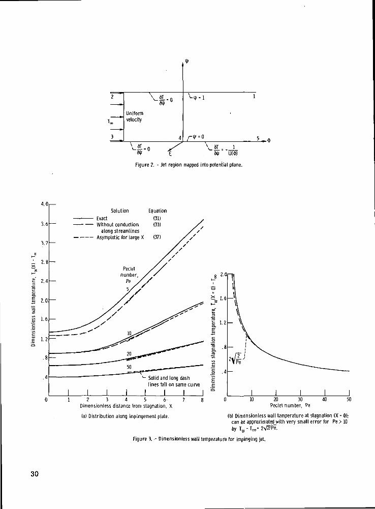
The solution for an inviscid two-dimensional jet slot jet striking a plane is availablein many textbooks as an example of conformal mapping applied to free jet theory. In thecourse of the solution the jet is transformed into a potential plane as shown in figure 2.In this plane the flow has a uniform velocity and is from left to right in a two-dimensionalchannel of unit height. The mapping functions relating the potential and physical planescan be obtained as a special case of the results in reference 9.
8
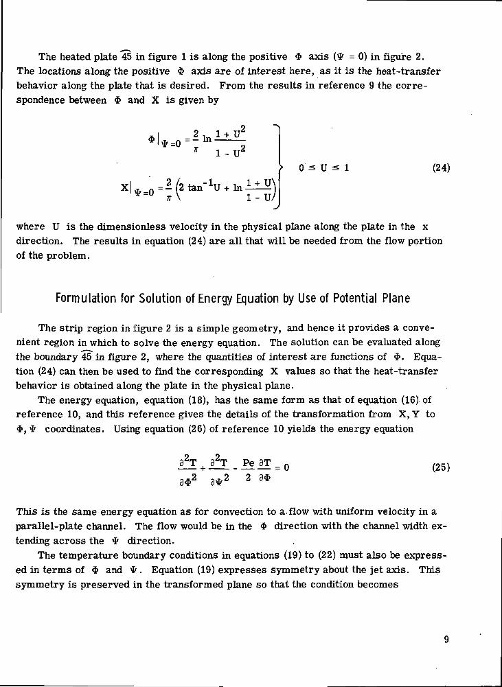
The heated plate 45 in figure 1 is along the positive * axis (^ = 0) in figure 2.The locations along the positive $ axis are of interest here, as it is the heat-transferbehavior along the plate that is desired. From the results in reference 9 the corre-spondence between $ and X is given by
1 - U
0 < U ̂ 1 (24)
where U is the dimensionless velocity in the physical plane along the plate in the xdirection. The results in equation (24) are all that will be needed from the flow portionof the problem.
Formulation for Solution of Energy Equation by Use of Potential Plane
The strip region in figure 2 is a simple geometry, and hence it provides a conve-nient region in which to solve the energy equation. The solution can be evaluated alongthe boundary 45 in figure 2, where the quantities of interest are functions of $. Equa-tion (24) can then be used to find the corresponding X values so that the heat-transferbehavior is obtained along the plate in the physical plane.
The energy equation, equation (18), has the same form as that of equation (16) ofreference 10, and this reference gives the details of the transformation from X, Y to$, * coordinates. Using equation (26) of reference 10 yields the energy equation
(25)
This is the same energy equation as for convection to a. flow with uniform velocity in aparallel-plate channel. The flow would be in the $ direction with the channel width ex-tending across the ^ direction.
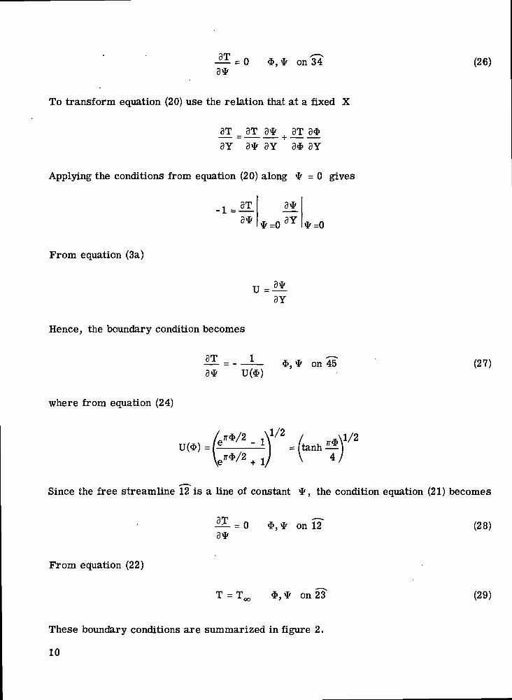
The temperature boundary conditions in equations (19) to (22) must also be express-ed in terms of $ and *. Equation (19) expresses symmetry about the jet axis. Thissymmetry is preserved in the transformed plane so that the condition becomes
= 0/
on 34 (26)
To transform equation (20) use the relation that at a fixed X
_3T _ 3T 3fr | 3T 3$
3Y 3* 3Y 3* 3Y
Applying the conditions from equation (20) along # = 0 gives
-1 = 3T
3* 3Y
From equation (3a)
3Y
Hence, the boundary condition becomes
3T
3*
where from equation (24)
on 45 (27)
Since the free streamline 12 is a line of constant ^, the condition equation (21) becomes
= 0 on 12 (28)
From equation (22)
T = T $, * on 23 (29)
These boundary conditions are summarized in figure 2.
10

In the potential plane (fig. 2) the situation is a channel flow with uniform velocity(i. e. , a moving slab) and a uniform entering fluid temperature T . Equation (25) is
f\ pthe convection equation with the axial conduction term 8 T/3$ included. The channelboundary conditions correspond to insulated walls except for a nonuniform heat additionalong the positive <£ axis . The solution can be obtained by utilizing some results fromreference 6. The desired result is the temperature distribution along the plate that thejet is impinging against. This can also be expressed in terms of a local Nusselt numberalong the plate. The local heat-transfer coefficient is h = <lw/(tw - t^). Then the localNusselt number based on the jet width 2b is
(30)
Solution of Energy Equation
Equation (8) on page 268 of reference 6 gives the temperature on the surface of aslab that is moving past a line source of heat. If superposition is used to obtain the ef-fect of a distribution of line sources, the solution can be found for the present problem.A difficulty is that the result given in reference 6 is valid only for positive distancesalong the surface away from the line source. A relation valid for both positive and neg-ative distances is needed to superpose the line sources and obtain a continuous sourcedistribution as given by -1/U(<1>) in figure 2. The details of the solution are given inappendix A, and the final result for the wall temperature along the positive $ axis(segment 45) is given by
11

- T = —
(Pe/4)($-7?) jl-[l+(4nWPe)2]1/2]
dij
[ r 91 i/2"]-(Pe/4)(?/-*Hl+ l+(4mjr/Pe) fL -I J
e L ^.
/tanh M\V 4/
\- drj
//
(3D
Equation (24) is then used to transform from $ to X, and T (X) - T^ can then be\nr
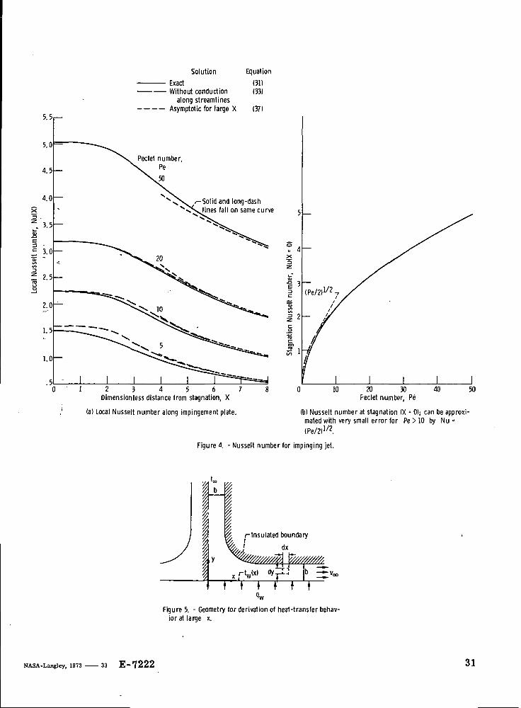
plotted along the impingement plate. The expression has been evaluated by numericalintegration, and results are given in figure 3(a) for Pe = 5, 10, 20, and 50. The localNusselt number is obtained from equation (30) and is plotted in figure 4(a).
Simplified Solution Neglecting Axial Conduction
In channel-flow heat-transfer analyses (ref. 11), the neglect of axial conductionproduces only a small error for Pe between 10 and 100, and for Pe > 100 the error isnegligible. Hence, it is worthwhile to examine here an approximate solution for whichthe axial conduction (conduction along the streamlines when transformed back into thejet geometry) is neglected. Compared with equation (31), this provides a much moresimple solution that is convenient to evaluate and is accurate when Pe is sufficientlylarge. With this assumption the energy equation (25) simplifies to
12

which is of the same form as the transient-heat-conduction equation. The boundarycondition (29) now applies along the axis $ = 0. The problem is the same as that for aplate of unit thickness that is initially at uniform temperature and that has one boundarykept insulated and one boundary with a heat input that varies with time. The solution canbe obtained by using a superposition in time of the uniform-heat-flux solution in equa-tion (4) on page 112 of reference 6. The derivation is given in appendix B with the re-sult that the wall temperature is given by
Tm(*) - Te
Equation (24) is used to obtain * values corresponding to the desired X values, andthe TW(X) are then evaluated by numerically integrating equation (33) for these $. Thewall temperature distribution and corresponding Nusselt number distribution are plottedin figures 3 (a) and 4(a) for various Pe.
Simplified Solution Neglecting Axial Conduction and Upper Boundary
The heat transfer in the vicinity of the stagnation region is sufficiently distant fromthe jet free streamlines that it is worth considering the solution of the energy equationwhere the effect of the upper boundary in figure 2 is neglected. As explained in the pre-vious section, the solution with axial conduction neglected is then the same as the solu-tion for the transient-heat-conduction equation - in this instance for a semi-infinite re-gion. From reference 6 (p. 76, eq. (9)) the solution for TW can be written as
$IM172
jpj JoU(*-
13
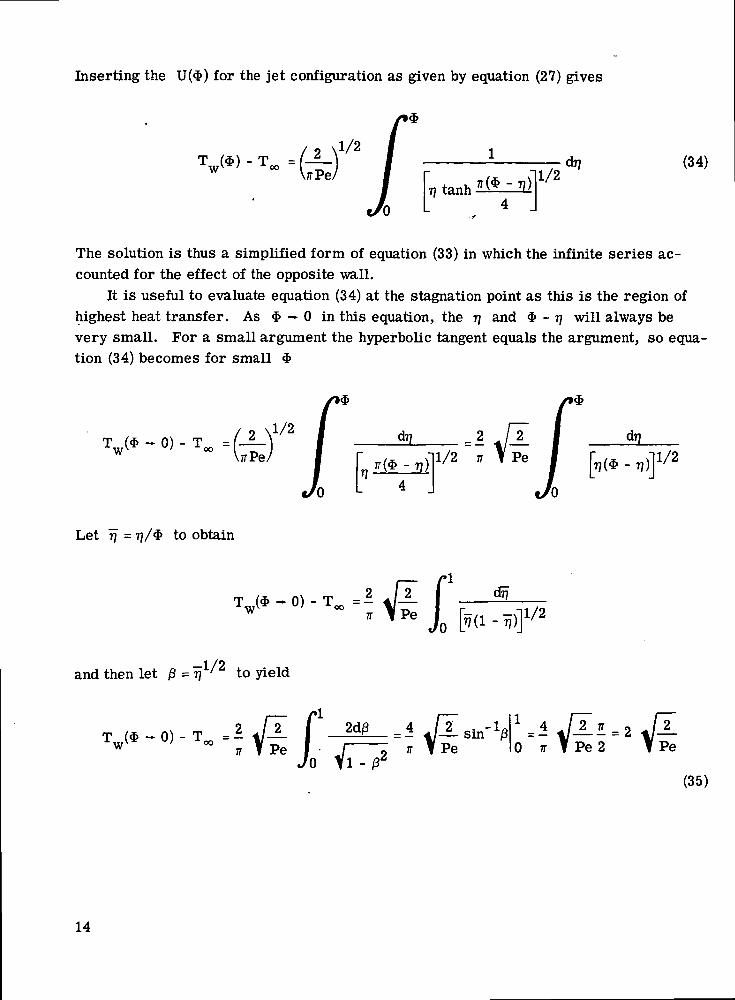
Inserting the U(*) for the jet configuration as given by equation (27) gives
=o-\XjrPe/
tanh11/2
(34)
The solution is thus a simplified form of equation (33) in which the infinite series ac-counted for the effect of the opposite wall.
It is useful to evaluate equation (34) at the stagnation point as this is the region ofhighest heat transfer. As $ — 0 in this equation, the TJ and $ - TJ will always bevery small. For a small argument the hyperbolic tangent equals the argument, so equa-tion (34) becomes for small *
— 0^ - T -u/ -"- ~
Let TJ = 77/* to obtain
- 0) -
and then let j3 = rj to yield= 1/2
- 0) -
siji f 1 s _"" Jn l7?^ -^1vU L J
1/2
% TPe I • J—JO Ifl -
IT f Pe 0 TT f Pe2
(35)
14
From equation (30)
Nu($ - 0) = = t/— ' (36)
Limiting Values for Large Values of Dimensionless Coordinate X
For large X it is possible to obtain a simple limiting solution. From figure 1 it isevident that for large X the situation is a channel flow, and with viscous effects neglect-ed, the velocity is uniform. The channel is bounded at the top by the free streamline,which is assumed insulated, and at the bottom by the plate, which has a uniform heataddition. This region is treated as a channel flow in appendix C, and the result for thewall temperature at large X is
VX)-Tco = —x + -Pe 3
This is compared with the solutions with and without axial conduction in figures 3(a) and4(a).
DISCUSSION
The condition considered here is for the impingement plate being heated uniformly,and the analysis yields the temperature distribution along the plate. The results areshown in figure 3; part (a) gives the temperature distribution along the plate, andpart (b) gives the value at the stagnation point. The solid curves are the exact solutionas given by equation (31), and as is typical of liquid metals, the results depend only onthe single parameter Pe which does not involve viscosity. Numerical values are givenin table I. As expected for a stagnation type flow, the highest heat transfer is at thestagnation point, and this is shown by the wall temperature being lowest at X = 0. Theconvective heat transfer should increase with the value of Pe, and the manner of thisincrease is revealed in figure 3. The heat-transfer characteristics can also be ex-pressed in the form of a local Nusselt number which is a reciprocal relation to the walltemperature, as shown by equation (30). The Nusselt number distribution along theplate and the stagnation Nusselt number are shown in figures 4(a) and (b).
15
An increase in convection, which corresponds to an increase in Peclet number,should diminish the effect of conduction along the streamlines, and the solution in equa-tion (33) should then apply. This relation is plotted as the long-dash curves in fig-ures 3(a) and 4(a). It is evident that the conduction term can be neglected, and the errorwill be within a few percent for Pe greater than about 10. Hence, unless Pe is some-what lower than 10, it is unnecessary to evaluate the exact solution as the simpler equa-tion (33) will suffice.
At stagnation the neglect of the upper boundary and conduction along the streamlinesleads to the following simple relations from equations (35) and (36):
TW(X = 0 ) -T =2 t/— (38a)
(38b)
As shown by the curves in figures 3(b) and 4(b), these relations are very good approxi-mations for Pe > 10. For low Pe the conduction along the streamlines at stagnation de-creases the heat transfer somewhat, as evidenced by the exact solution in figure 4(b)being below the solution neglecting heat conduction. Heat is conducted upstream into theflow as it approaches the plate, and this tends to thicken the thermal boundary layernear stagnation and decrease the heat transfer. Figure 3 shows that the wall tempera-ture is fairly uniform in the vicinity of stagnation. Hence, the stagnation results inequations (38) should also apply for the boundary condition of uniform wall temperature.
Equation (37) provides a simple asymptotic result for large X. The results showthat this is a good approximation for X larger than about 6 with Pe greater than about10. At smaller X the asymptotic solution begins to deviate gradually from the exactresults, and the approximation is not very good for X less than about 4 for the Pevalues considered in this report.
The analysis in reference 7 is concerned with gases and liquids, 0. 7 < Pr < 10,rather than the low Prandtl number range typical of liquid metals in the present report.The boundary condition at the impingement plate in reference 7 is a specified uniformwall temperature rather than a uniform heat flux like that treated in this report. For0 ^ Pr ^ 10 the viscous boundary layer is almost as thick or is thicker than the thermallayer, so that a boundary-layer analysis for the flow is required. The solution is ob-tained numerically with the jet potential flow solution used for the external flow. Theanalysis also includes the jet nozzle being at various distances from the plate. Forlarge nozzle distances from the plate, as in the present report, the variations of Nusseltnumber along the plate have the same general trends as those obtained in this report.
16

At the stagnation point the correlation obtained in reference 7 is Nu = 0. 51 Re ' Pr1/9 1/2as compared with Nu = 0. 707 Pe ' - 0. 707(RePr) ' for the present report. The cor-
1 /x nrelation in reference 7 can be rearranged into Nu = 0.51(RePr) ' /Pr1/2 0 1270. 51 Pe ' /Pr . Viscosity appears only in the Prandtl number, and since the
Prandtl number is to a small power, the heat-transfer behavior at the stagnation pointis not very viscosity dependent.
CONCLUSIONS
An analysis has been performed combining free jet theory and a transformation ofthe energy equation into the potential plane to obtain the heat-transfer behavior of animpinging liquid-metal jet. The jet is two-dimensional in Cartesian coordinates andstrikes a plate that is uniformly heated. The temperature distribution and heat-transfercoefficient are evaluated along the plate as a function of the Peclet number Pe. Aswould be expected, the maximum heat-transfer coefficient is at the stagnation point. Ata distance larger than about 6 jet half-widths from stagnation and for Pe > 10, the re-sults can be approximated quite well by an asymptotic relation that considers the jetregion to act like a channel flow. Heat conduction along the streamlines is not very sig-nificant when Pe is greater than 10. For this Pe range, the Nusselt number Nu at stag-nation can be approximated quite well by Nu = -\fPe/2. This result should also apply forthe boundary condition of uniform wall temperature because the present solution yieldedalmost uniform wall temperatures in the vicinity of stagnation.
Lewis Research Center,National Aeronautics and Space Administration,
Cleveland, Ohio, February 7, 1973,501-24.
17

APPENDIX A
SOLUTION OF ENERGY EQUATION
The solution can be obtained by starting with the equation for a stationary pointsource of heat on one side of a moving slab with the other side of the slab insulated. Bysuperposition the point source is used to obtain the solution for a line source. Then asuperposition of line sources can be used to build up the heat source distribution speci-fied by the boundary condition equation (27) along the positive axis.
For a slab of unit thickness, 0 < * < 1, moving with a unit velocity (fig. 2) the tem-perature distribution produced by a unit point heat source fixed at the origin, $ = * =|=0 (the £ is a coordinate axis perpendicular to $ and *), is obtained from refer-ence 6, page 268, equation (7), as
/ 4 \ 2 2 21 + (_L) m V
W
1/2)Uos(m7r*)|e*Pe/4
m=l (Al)
Integrating over £ yields the temperature distribution for a line source along theaxis
m=l
To carry out this integration the result from reference 12, page 417, is used that
18
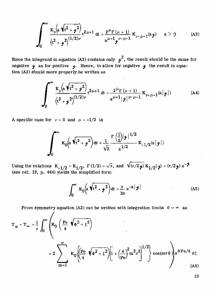
E±i)_K i ;ujU_1(a^) a > 9 (A3)
Since the integrand in equation (A3) contains only ^ , the result should be the same fornegative ^ as for positive A. Hence, to allow for negative ^ the result in equa-tion (A3) should more properly be written as
K .(a Vt2 +
(A4)
A specific case for v = 0 and M = -1/2 is
Kja
1/2
V2" a1/2(a | f | )
Using the relations K_1//2 - K X / 2 , T (1/2) = Vir, and VOr/2^) K1/2(^) = (jr/2^)(see ref. 13, p. 444) yields the simplified form
2a(A5)
From symmetry equation (A2) can be written with integration limits 0 — °° as
T - T =w °°P2 V*27
M(f V*2^ 1 + 1—
m=l (A6)
19

Equation (A6) is integrated by use of equation (A5) to yield
2 Pe
m=l
r 9l 1/2-(Pe/4)|l+(4m7r/PerJ
IT e2
Pe4
"l+f-lfmV\Pe/
1/2
*l
Simplifying and evaluating at the wall ^ = 0 give
TW^- T°o = —w Pe
\
(Pe/4)|*- | * | [l+(4m7r/Pe)2]1/2!
(**»}\ P e /
1/2
(A7)
Equation (A7) gives the wall-temperature distribution produced by a line source ofunit strength per unit length along the ^ axis in figure 2. Superposition can now be
20

applied along the positive $ axis to obtain the effect of the source distributionwhich resulted from the imposed uniform heat flux in the physical plane being trans-formed into the potential plane. If H($) is the response to a unit line source, and F($)is the distribution of sources, the wall-temperature distribution can be obtained bysuperposition a s . • • - ' •
Using equation (A7) for H($) gives
(A8)
w
(Pe/4)|(*-Tj)- | *-?} [l* (4mir/Pe)2]1/2)
511/2drj
(A9)
The U(TJ) is inserted from equation (27) and the integral is divided into two regions de-pending on whether 77 < $ or r\ > * to obtain the final form
21

T = —°° Pe
*l +
=0
s-(Pe/2)(Tj-*)drj
\ P e /m=l
1/2
ftanhT]=$
13 V4 /
1/2
1/21
4
1/2drj
}drj (A10)
22

APPENDIX B
SOLUTION NEGLECTING AXIAL CONDUCTION
In reference 6, page 112, the transient temperature solution is given for a heat fluxsuddenly imposed at one surface of a slab with the other surface of the slab insulated.Since equation (32) has the same form as the transient heat conduction equation, thissolution can be applied after changing the nomenclature. The $ is analogous to time inthe transient problem, and since the heat flux varies with $ in the present case, thesolution is the same as a transient solution in Which the imposed heat flux varies withtime. The superposition theorem for the variable-heat-flux solution is
•rJO
dF- tj) d?]
dTJ (Bl)
where 1/U($) is given by equation (27), and F is the response to a suddenly imposedheat flux of unit magnitude.
From the solution in reference 6 the F is given by
X.
m
/ 2 X1/2
— *)\Pe /
m + 1
/2 \1/2
(—*)\Pe / Jm=0
where
ierf c ^ = erf c
The derivative of this function is given by
= (-erfc
23

Using this relation gives
dF = / 2 V1/2 •ierfc m
m=0
+ ierfc m + 1 m
Pe
m
l/2erfc
\Pe
m + 1
f-*)1/2i,Pe )
erfc m
Pe
(B2)
When the definitions of ierfc 4 arid erfc £ ;are used, equation (B2) reduces to
oo . •
dF /_2_\1/2 JL V L-m2/(2/Pe)* + e-(m+l)2/(2/Pe)*l
m=0
(B3)
Substitute equation (B3) into equation (Bl) and use equation (27) for U to obtain the de-sired final result for the wall-temperature distribution
(B4)
24

APPENDIX C
LIMITING HEAT TRANSFER AT LARGE VALUES
OF DIMENSIONLESS COORDINATE X
For large x the flow as shown in figure 5 is a flow with uniform velocity in a chan-nel with one wall heated and one wall insulated. An overall heat balance is now taken onthe flow region from the fluid entrance at large y to the region at large x, where thevelocity is uniform and equal to v^ . This yields for large x
qwX=bv c opCp[ t(x)-tJ (Cl)
where t (x) is the mean temperature for uniform velocity (see eq. (C7)) obtained as1 /"b
t ( x ) = T - Aj t(x, y) dy. Equation (Cl) determines the t (x) since q is a specified quan-tity.
A heat balance on a differential element in the fluid gives
(C2)
For fully developed heat transfer with uniform heat addition the temperature distributionrises linearly with x and hence has the form
t(x,y) = C 1 x+f(y) (C3)
2 2The axial conduction term k(3 t/3x ) is thus zero, and substitution of equation (C3) into(C2) yields
k—-v^pCpCj (C4)dy2
Since in the fully developed region the shape of the temperature distribution is not chang-ing, equation (Cl) yields
]*.=!*.=—^L-^CI (C5)3x 3x bv^pC
25

Then combining equations (C5) and (C4) gives
d2fdy'.2 kb
Integrate once and apply the boundary condition that 3t/8y = 8f/3y = 0 at y = b to ob-tain
dy kb
A second integration results in
The integrated average temperature is
(C6)
rb rJo udv v~./o
b b(C7)
Substituting for t by use of equations (C3), (C5), and (C6) gives
b kb \2dy
t (x)=i |*> \VooPC_ kb 3
Using t(x) from equation (Cl) gives
qwb
— t-t -t- ̂ 2
'P bVcoPCp 3k
26

so that
C 2= t c o + —1 3k
Combining equations (C3), (C5), (C6), and (C8) gives the temperature distribution
bv^pCp kb2 / 3k
Evaluating at y = 0 to obtain the wall temperature yields
ww bvwpCp 3k
In dimensionless form the final result is
27
REFERENCES
1. Birkhoff, Garrett; and Zarantonello, E. H.: Jets, Wakes, and Cavities. AcademicPress, Inc., 1957.
2. Milne-Thomson, L. M.: Theoretical Hydrodynamics. Seconded., The MacmillanCo., 1950.
3. Schach, W.: Umlenkung eines kreisformigen Flussigkeitsstrahles an einer ebenenPlatte senkrecht zur Stromungsrichtung. Ing. -Arch., vol. 6, no. 1, 1935,pp. 51-59.
4. Saad, Michel A.; and Antonides, Gene J.: Flow Pattern of Two Impinging CircularJets. AIAA J., vol. 10, no. 7, July 1972, pp. 929-931.
5. Grosh, R. J.; and Cess, R. D.: Heat Transfer to Fluids with Low Prandtl Numbersfor Flow Across Plates and Cylinders of Various Cross Section. ASME Trans.,vol. 80, no, 3, Apr. 1958, pp. 667-676.
6. Car slaw, Horatio S.; and Jaeger, J. C.: Conduction of Heat in Solids. Second ed.,Oxford Univ. Press, 1959.
7. Miyazaki, H.; and Silberman, E.: Flow and Heat Transfer on a Flat Plate Normalto a Two-Dimensional Laminar Jet Issuing from a Nozzle of Finite Height. Int.J. Heat Mass Transfer, vol. 15, Nov. 1972, pp. 2097-2107.
8. Eckert, E. R. G.; and Drake, Robert M., Jr.: Heat and Mass Transfer. Seconded., McGraw-Hill Book Co., Inc., 1959.
9. Gedney, Richard T.; and Siegel, Robert: Inviscid Flow Analysis of Two ParallelSlot Jets Impinging Normally on a Surface. NASA TN D-4957, 1968.
10. Siegel, Robert; and Goldstein, Marvin E.: Analytical Method for Steady State HeatTransfer in Two-Dimensional Porous Media. NASA TN D-5878, 1970.
11. Schneider, P, J.: Effect of Axial Fluid Conduction on Heat Transfer in the EntranceRegions of Parallel Plates and Tubes. ASME Trans., vol. 79, no. 4, May 1957,pp. 765-773.
12. Watson, George N.: A Treatise on the Theory of Bessel Functions. Second ed.,Cambridge Univ. Press, 1966.
13. Abramowitz, M.; and Stegun, I. A., eds.: Handbook of Mathematical Functionswith Formulas, Graphs, and Mathematical Tables. Appl. Math. Ser. 55, NationalBureau of Standards, June 1964 (6th Printing, 1967).
28

TABLE I. - WALL TEMPERATURES ALONG
IMPINGEMENT PLATE
[From (eq. (31)]
Dimensionlesscoordinate,
X
01
2
345
67
8
Dimensionlesspotential,
*
0.1960.7673
1.61052.57003.56114.55925.56296.4835
Peclet number, Pe
5 10 20 50
Wall temperature, TW(X) - T^
1.3241.3661.4871.7492.1062.4962.8933.2953.663
0.893.902.935
1.0321.1911.3781.5741.7741.958
0.630.633.648.692.764.852.946
1.0451.136
0.397.400.409.435.474.519.563.607.646
V- -
-Free streamline
y.v4 x,u rtw(x)- - - '
u-v.
r n i l l fFigure 1. - Inviscid-irrotational jet impinging on plate with specified uniform
heat addition.
29
Uniformvelocity
v-Ul = 1
Figure 2. - Jet region mapped into potential plane.
4.0
3.6
3.2
2.4
aS 2.0
1.6
I 1.2
Solution EquationExact (31)Without conduction (33)
along streamlinesAsymptotic for large X (37)
Solid and long dashlines fall on same curve
1 2 3 4 5 6Oimensionless distance from stagnation, X
(a) Distribution along impingement plate.
2.0
£ 1.6
TSfe 1.2
10 20 30Peclet number, Pe
40 50
(b) Dimensionless wall temperature at stagnation (X = 0);can be approximated with very small error for Pe > 10by Tfl-Tco
Figure 3. - Dimensionless wall temperature for impinging jet.
30
SolutionExactWithout conduction
along streamlinesAsymptotic for large X
Peclet number,Pe
Equation(31)(33)
(37)
Solid and long-dashfall on same curve
1 2 3 4 5 6 7Dimensionless distance from stagnation, X
(a) Local Nusselt number along impingement plate.
10 20 30Peclet number, Pe
40 50
(b) Nusselt number at stagnation (X = 0); can be approxi-mated with very small error for Pe>lO by Nu •(Pe/2)1/2.
Figure 4. - Nusselt number for impinging jet.
b ^v*
Figure 5. - Geometry for derivation of heat-transfer behav-ior at large x.
NASA-Langley, 1973 33 E-7222 31

NATIONAL AERONAUTICS AND SPACE ADMINISTRATION
WASHINGTON. D.C. 2OS46
OFFICIAL BUSINESS
PENALTY FOR PRIVATE USE S3OO SPECIAL FOURTH-CLASS RATEBOOK
POSTAGE AND FEES PAIDNATIONAL AERONAUTICS AND
SPACE ADMINISTRATION
POSTMASTER : If Undeliverable (Section 158Postal Manual) Do Not Return
"The aeronautical and space activities of the United States shall beconducted so as to contribute . . . to the expansion of human knowl-edge of phenomena in the atmosphere and space. The Administrationshall provide for the widest practicable and appropriate disseminationof information concerning its activities and the results thereof."
—NATIONAL AERONAUTICS AND SPACE ACT OF 1958
NASA SCIENTIFIC AND TECHNICAL PUBLICATIONSTECHNICAL REPORTS: Scientific andtechnical information considered important,complete, and a lasting contribution to existingknowledge.
TECHNICAL NOTES: Information less broadin scope but nevertheless of importance as acontribution to existing knowledge.
TECHNICAL MEMORANDUMS:Information receiving limited distributionbecause of preliminary data, security classifica-tion, or other reasons. Also includes conferenceproceedings with either limited or unlimiteddistribution.
CONTRACTOR REPORTS: Scientific andtechnical information generated under a NASAcontract or grant and considered an importantcontribution to existing knowledge.
TECHNICAL TRANSLATIONS: Informationpublished in a foreign language consideredto merit NASA distribution in English.
SPECIAL PUBLICATIONS: Informationderived from or of value to NASA activities.Publications include final reports of majorprojects, monographs, data compilations,handbooks, sourcebooks, and specialbibliographies.
TECHNOLOGY UTILIZATIONPUBLICATIONS: Information on technologyused by NASA that may be of particularinterest in commercial and other non-aerospaceapplications. Publications include Tech Briefs,Technology Utilization Reports andTechnology Surveys.
Details on the availability of these publications may be obtained from:
SCIENTIFIC AND TECHNICAL INFORMATION OFFICE
N A T I O N A L A E R O N A U T I C S A N D S P A C E A D M I N I S T R A T I O NWashington, D.C. 20546