Embed Size (px)
Citation preview

AND
NASA TECHNICAL NOTE NASA TN D-7716
*-J
L. S. J.I
(NASA TN-D-7776) WD L
STIGATION W IND-TUNNELS-P-I ESSGR A WOF A MODEL OF A FREE-FLIGHT(IACESS 76 pC C.I. COlGURATION 7-26y 3CSCL C Unclas
WIND-TUNNEL FREE-FLIGHT INVESTIGATIONOF A MODEL OF A SPIN-RESISTANTFIGHTER CONFIGURATION
by Sue B. Grafton, Joseph R. Chambers,
and Paul L. Coe, Jr.
Langley Research CenterHampton, Va. 23665
NATIONAL AERONAUTICS AND SPACE ADMINISTRATION * WASHINGTON, D. C. * JUNE 1974
https://ntrs.nasa.gov/search.jsp?R=19740018330 2018-07-16T14:52:54+00:00Z

1. Report No. 2. Government Accession No. 3. Recipient's Catalog No.
NASA TN D-77164. Title and Subtitle 5. Report Date
WIND-TUNNEL FREE-FLIGHT INVESTIGATION OF A MODEL June 1974
OF A SPIN-RESISTANT FIGHTER CONFIGURATION 6. Performing Organization Code
7. Author(s) 8. Performing Organization Report No.
Sue B. Grafton, Joseph R. Chambers, and Paul L. Coe, Jr. L-9681
10. Work Unit No.9. Performing Organization Name and Address 501-26-04-02
NASA Langley Research Center 11. Contract or Grant No.
Hampton, Va. 2366513. Type of Report and Period Covered
12. Sponsoring Agency Name and Address Technical NoteNational Aeronautics and Space Administration 14. Sponsoring Agency CodeWashington, D.C. 20546
15. Supplementary Notes
Paul L. Coe, Jr., is an Assistant Research Professor in Engineering, The George WashingtonUniversity, Joint Institute for Acoustics and Flight Sciences.
Technical Film Supplement L-1152 available on request.
16. Abstract
An investigation was conducted to provide some insight into the features affecting thehigh-angle-of-attack characteristics of a high-performance twin-engine fighter airplane
which in operation has exhibited excellent stall characteristics with a general resistance to
spinning. Various techniques employed in the study included wind-tunnel free-flight tests,flow-visualization tests, static force tests, and dynamic (forced-oscillation) tests. In addi-
tion to tests conducted on the basic configuration, tests were made with the wing planform
and the fuselage nose modified.
The results of the study showed that the model exhibited good dynamic stability charac-
teristics at angles of attack well beyond that for wing stall. The directional stability of the
model was provided by the vertical tail at low and moderate angles of attack and by the fuse-
lage forebody at high angles of attack. The wing planform was found to have little effect on
the stability characteristics at high angles of attack. The tests also showed that although
the fuselage forebody produced beneficial contributions to static directional stability at high
angles of attack, it also produced unstable values of damping in yaw. Nose strakes located
in a position which eliminated the beneficial nose contributions produced a severe directional
divergence.
The investigation identified configuration features which promote spin resistance and
also defined test techniques and methods of analysis which can be applied early in design offuture configurations.
17. Key Words (Suggested by Author(s)) 18. Distribution Statement
Stall/spin Unclassified - Unlimited
Dynamic stability
High-performance fighter
STAR Category 02
19. Security Classif. (of this report) 20. Security Classif. (of this page) 21. No. of Pages 22. Price*
nclassified UUnclassified I7 $4.00
For sale by the National Technical Information Service, Springfield, Virginia 22151j

WIND-TUNNEL FREE-FLIGHT INVESTIGATION OF A MODEL
OF A SPIN-RESISTANT FIGHTER CONFIGURATION
By Sue B. Grafton, Joseph R. Chambers,
and Paul L. Coe, Jr.*
Langley Research Center
SUMMARY
An investigation was conducted to provide some insight into the features
affecting the high-angle-of-attack characteristics of a high-performance
twin-engine fighter airplane which in operation has exhibited excellent stall
characteristics with a general resistance to spinning. Various techniques
employed in the study included wind-tunnel free-flight tests, flow-visualization
tests, static force tests, and dynamic (forced-oscillation) tests. In addition
to tests conducted on the basic configuration, tests were made with the wing
planform and the fuselage nose modified.
The results of the study showed that the model exhibited good dynamic
stability characteristics at angles of attack well beyond that for wing stall.
The directional stability of the model was provided by the vertical tail at low
and moderate angles of attack and by the fuselage forebody at high angles of
attack. The wing planform was found to have little effect on the stability
characteristics at high angles of attack. The tests also showed that although
the fuselage forebody produced beneficial contributions to static directional
stability at high angles of attack, it also produced unstable values of damping
in yaw. Nose strakes located in a position which eliminated the beneficial
nose contributions produced a severe directional divergence.
The investigation identified configuration features which promote spin
resistance and also defined test techniques and methods of analysis which can
be applied early in design of future configurations.
*Assistant Research Professor in Engineering, The George Washington
University, Joint Institute for Acoustics and Flight Sciences.

INTRODUCTION
Experience has shown that many high-performance fighter airplanes are
susceptible to a lateral-directional divergence (sometimes referred to as
nose-slice) at high angles of attack. (See, e.g., ref. 1.) This type of
divergence usually leads to inadvertent spins, and spin recovery for
present-day fighters is often difficult or impossible. Therefore, there is an
urgent need to develop guidelines for use in the design of future tactical
aircraft in order to eliminate instabilities and insure good inherent
characteristics at high angles of attack. The National Aeronautics and Space
Administration currently has a broad research program underway to provide these
guidelines. One element of the program involves identification of airframe
design features which promote good stall and spin characteristics.
The present investigation was conducted in order to provide some insight
into the features affecting the stability characteristics at high angles of
attack of a high-performance twin-engine fighter which in operation has
exhibited outstanding stall and spin characteristics. These characteristics,
which result in a general resistance to spins, include positive directional
stability through the stall with no tendency to diverge and no significant
adverse yaw due to aileron deflection at high angles of attack.
A wind-tunnel investigation was made with a 0.17-scale model of the
airplane in order to define some of the more important geometric and aerodynamic
characteristics responsible for the good stall and spin characteristics. The
study included wind-tunnel free-flight tests, flow-visualization tests, static
force tests, and dynamic (forced-oscillation) force tests.
In addition to the tests conducted for the basic configuration, tests
were made with the wing planform changed to swept and delta designs. The basic
and delta wings were also tested in a high position on the fuselage, and
fuselage forebody strakes were added in order to determine the effects of
these features on stability and control at high angles of attack.
Selected scenes from a motion picture of the free-flight tests have been
prepared as a film supplement available on loan. A request card and a
description of the film (L-1152) are included at the back of this report.
2

SYMBOLS
All longitudinal forces and moments are referred to the wind-axis system
and all lateral-directional data are referred to the body-axis system shown in
figure 1. All force-test data are referred to a moment reference center
located longitudinally at 18 percent of the mean aerodynamic chord for the
basic wing. The vertical location of the moment reference center was 0.02 per-
cent of the mean aerodynamic chord above the wing-chord reference line at the
plane of symmetry. All measurements were reduced to standard coefficient form
on the basis of the geometric characteristics of each individual wing planform.
In order to facilitate international usage of data presented, dimensional quan-
tities are presented both in the International Systems of Units (SI) and in the
U.S. Customary Units. Measurements and calculations were made in the U.S.
Customary Units. Conversion factors for the two systems may be found in refer-
ence 2.
b wing span, m (ft)
c mean aerodynamic chord, m (ft)
CA axial-force coefficient, FA/q S
CD drag coefficient, FD/q S
CL lift coefficient, FL/q S
C rolling-moment coefficient, MX/q.Sb
Cm pitching-moment coefficient, My/qaSc
C yawing-moment coefficient, MZ/q Sb
CN normal-force coefficient, FN/qS
5

C side-force coefficient, Fy/qS
f frequency of oscillation, Hz
FA axial force, N (Ib)
FD drag force, N (Ib)
FL lift force, N (lb)
FN normal force, N (lb)
F side force, N (lb)
IX moment of inertia about X body axis, kg-m2 (slug-ft2 )
Iy moment of inertia about Y body axis, kg-m2 (slug-ft2 )
I Z moment of inertia about Z body axis, kg-m2 (slug-ft 2 )
wb Ck reduced-frequency parameter, 2 or 2V
MX rolling moment, m-N (ft-lb)
My pitching moment, m-N (ft-lb)
MZ yawing moment, m-N (ft-lb)
p roll rate, rad/sec
q pitch rate, rad/sec
q. dynamic pressure, N/m 2 (ib/ft2 )
4~
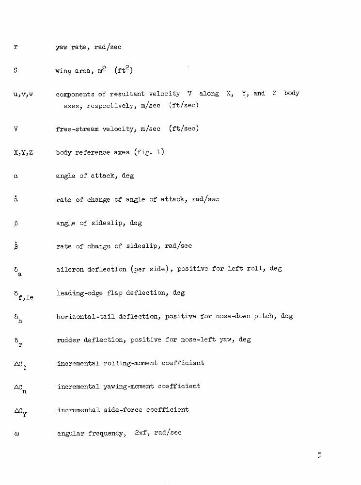
r yaw rate, rad/sec
S wing area, m2 (ft2 )
U,vW components of resultant velocity V along X, Y, and Z body
axes, respectively, m/sec (ft/sec)
V free-stream velocity, m/sec (ft/sec)
X,Y,Z body reference axes (fig. 1)
a angle of attack, deg
Srate of change of angle of attack, rad/sec
P angle of sideslip, deg
rate of change of sideslip, rad/sec
a aileron deflection (per side), positive for left roll, dega
5fle leading-edge flap deflection, deg
Sh horizontal-tail deflection, positive for nose-down pitch, deg
S rudder deflection, positive for nose-left yaw, deg
rincremental rolling-moment coefficient
C incremental yawing-moment coefficientn
ACy incremental side-force coefficient
CD angular frequency, 2iTf, rad/sec
5

c cn acyCI = CnP = 6 Cy =
Cn~dyn Cn - I- C sin a
6C 6 Cn 6CYCIp=l pb Cn Y = pb
2V 2V 2V
c acn acy2 n Y
C = C Cy =
Cr rb Cnr rb CYr rb2V 2V 2V
6C 6CN 6CACm C CA =
2V 2V 2V
m N CAC - CN. CA -fa 61 a
2V 2V 2V
MODEL, APPARATUS, AND TESTING TECHNIQUES
Basic Configuration
A three-view sketch showing the basic configuration of the model is
presented in figure 2, photographs of the model are presented in figure 3,
and mass and geometric characteristics are listed in table I. The model was
6

constructed primarily of molded fiberglass and was a 0.17-scale model of the
full-scale airplane.
The model was powered by compressed air which was brought into the top
of the model by flexible plastic tubing and ejected from metal tubes located
inside the model near the rear of the fuselage. This ejector system simulated
flow through the engines, since the model was tested with the engine inlets and
interior of the model open.
The longitudinal control surface consisted of an all-movable horizontal
tail, the lateral control surfaces were conventional ailerons, and the
directional control surface was a conventional rudder. For manual control by
the pilot, the control surfaces were actuated by electropneumatic servos which
provided a full-on or full-off flicker-type deflection. Each actuator had a
motor-driven trimmer which was electrically operated by the pilots so that
controls could be rapidly trimmed in flight. The systems for pitch and roll
control were also connected to individual rate damper systems. The rate dampers
consisted of rate gyroscopes driven by compressed air which actuated the
surfaces in proportion to pitch and roll rates. The control-surface deflections
used during the flights were as follows:
Pilot Damper Maximum(flicker) (proportional) available
Horizontal tail, deg . . . . . ±5 ±5 5 to -25
Ailerons (per side), deg . . . 0 ±5 ±30
Rudder, deg . . . . . . . . . ±10 to ±30 -- ±30
Deflection of the horizontal tail on the full-scale airplane is limited to 170
trailing edge up, but increased travel was provided for the model in order to
investigate angles of attack beyond those obtainable'in lg flight at full scale.
Modified Configuration
One airframe component expected to have significant effects on the
stability and control of the model at high angles of attack was the wing.
Past studies (see refs. 3 and 4, e.g.) have shown that wing planform
7

characteristics, such as sweepback and taper ratio, together with the vertical
location of the wing on the fuselage can have large effects on lateral-
directional stability at high angles of attack. In order to evaluate the
effects of wing modifications, the additional wings and wing-fuselage
combinations shown in figures 4, 5, and 6 were tested. In addition to the
basic wing, a swept wing (similar in planform to that employed by the
configuration of ref. 1) and a delta wing were tested. As shown in figure 5,
the basic wing and the delta wing were also tested in a high position with
modified engine inlets. (The engine inlets were modified in order to smooth
the intersection of the high wing and the fuselage.) All wings were of equal
area and of relatively equal weights, so that the flight tests were conducted
with a constant value of wing loading. Aspect ratio and wing span varied with
each wing design. (See table I.) The location of the 0.25E point was constant
for all configurations tested. The additional wings incorporated conventional
ailerons for roll control. Plan views of the configuration with the various
wings are shown in figure 6.
Tests were also conducted to determine the effects of the symmetrical nose
strakes shown in figure 7. The strakes were designed to eliminate asymmetric
yawing moments and unstable values of damping in yaw at high angles of attack,
as discussed in reference 5. As a further element of studies of the effects of
the fuselage nose, the aerodynamic characteristics of the isolated nose of the
basic configuration were determined in tests of the nose alone (fig. 8).
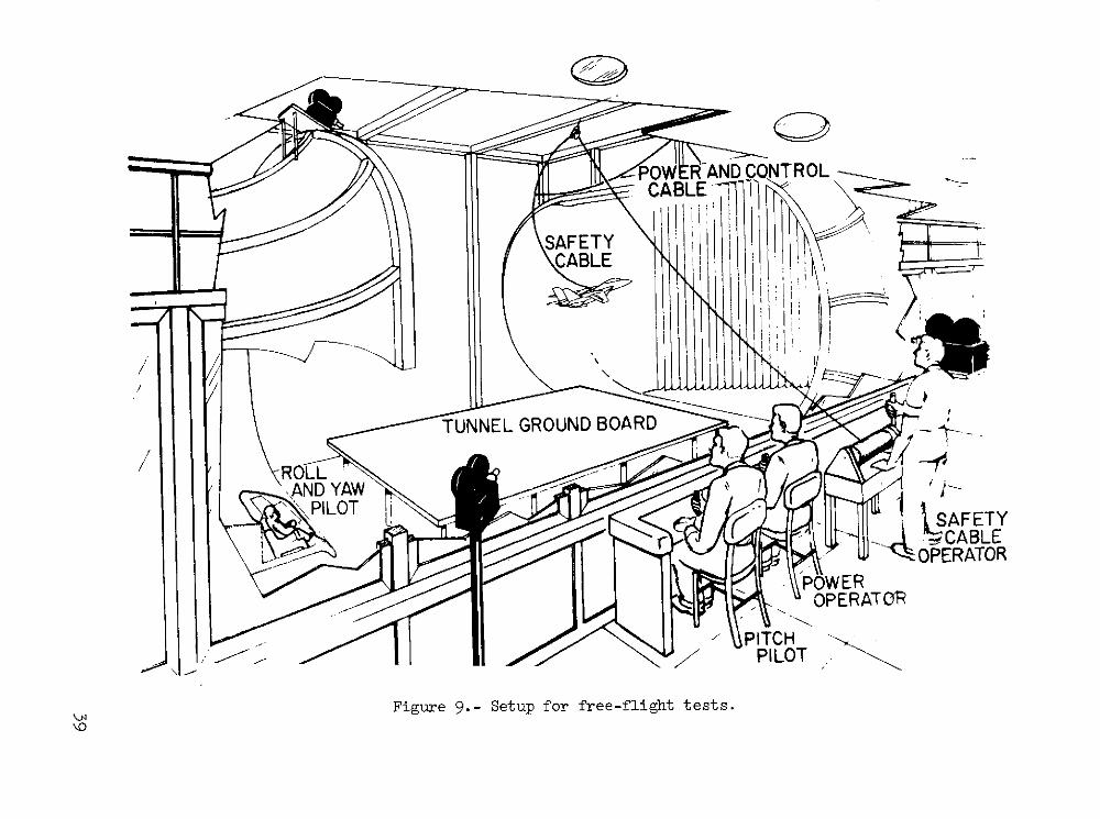
Free-Flight Test Technique
The test setup for the free-flight tests is shown in figure 9. The model
was flown without restraint in the 9- by 18-m (30- by 60-ft) open-throat test
section of the Langley full-scale tunnel and was remotely controlled about all
three axes by two human pilots. One pilot, who controlled the model about its
roll and yaw axes, was stationed in an enclosure at the rear of the test
section. The second pilot, who controlled the model in pitch, was stationed at
one side of the tunnel. Pneumatic and electric power and control signals were
supplied to the model through a flexible trailing cable which was made up of
wires and light plastic tubes. The trailing cable also incorporated a
8

0.318 -cm-diameter (1/8-in.) steel cable that passed througn a pulley above thE
test section. This section of flight cable was used to catch the model when an
uncontrollable motion or mechanical failure occurred. The entire flight cable
was kept slack during the flights by a safety-cable operator using a high-speed
pneumatic winch. A further discussion of the free-flight technique, including
the reasons for dividing the piloting tasks, is given in reference 6.
TESTS
Free-Flight Tests
Free-flight tests were conducted to determine the dynamic stability and
control characteristics of the following model configurations at high angles
of attack:
1. Low-wing configurations
(a) Basic
(b) Swept
(c) Delta
2. High-wing configurations
(a) Basic
(b) Delta
The flight tests included steady flights at high angles of attack up to and
including stall, studies of pilot lateral-control techniques at high angles of
attack, and evaluation of the effects of artificial rate damping. In addition,
a few flight tests were made to determine the effects of wing leading-edge flap
deflection and wing-tip fuel tanks on the characteristics of the basic
configuration. The results of the flight tests were mainly qualitative and
consisted of pilot opinion of the behavior of the model. Motion-picture
records were made of all flights and selected scenes are included in the film
supplement to this report.
Force and Flow-Visualization Tests
Static and dynamic (forced-oscillation) tests were conducted in the
Langley full-scale tunnel at a Reynolds number, based on the mean aerodynamic
chord of the basic wing, of about 0.65 x 10⁶. This value of Reynolds number
9

was about the same as that for the flight tests, which, of course, varied with
lift coefficient. Static tests were made for a range of angle of attack from
-10° to 400 over a range of angle of sideslip of ±400 for the configurations
flown and included component-buildup tests and control-effectiveness tests.
The forced-oscillation tests were made in pitch, roll, and yaw to determine the
dynamic stability derivatives for the low-wing configurations. The tests were
made with an angular amplitude of ±50 and an oscillation frequency of 1 Hz,
which resulted in values of the reduced-frequency parameter k of 0.181 for
the rolling and yawing tests and 0.056 for the pitching tests. Conventional
wind-tunnel corrections for flow angularity have been applied to all force data.
A limited number of tuft, smoke, and oil flow-visualization tests were also
conducted to determine flow characteristics around the model.
RESULTS AND DISCUSSION OF FORCE TESTS
Static Longitudinal Characteristics
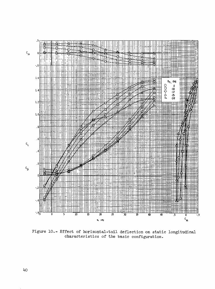
Basic configuration.- The static longitudinal characteristics of the basic
configuration are presented in figures 10 to 12. The data of figure 10 show the
effects of horizontal-tail deflection on the longitudinal characteristics. The
model was statically stable and the horizontal tail was effective over the range
of angle of attack tested. With the tail removed, the lift curve indicated
major wing stall near a = 17 ; this condition was verified by tuft flow-
visualization tests. With the tail on, the lift curve did not exhibit a sharp
break. The data also show that for the particular center of gravity of the tests
(0.186), deflection of the tail to the maximum available on the full-scale
airplane (8h = -170 would trim the model at about a = 210 for 1g flight.
As previously pointed out, the horizontal-tail travel was extended to 5h = -250
for the present model in order to investigate stability and control character-
istics at angles of attack higher than those obtained in 1 g flight.
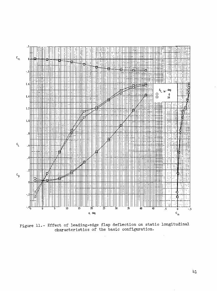
The data of figure 11 show that deflection of the wing leading-edge flap
produced a small increase in lift at high angles of attack and no effect on
longitudinal stability. Addition of wing-tip tanks to the basic configuration
had no significant effects on the longitudinal aerodynamic characteristics of
the model, as shown in figure 12.
10
Modified configuration.- The longitudinal characteristics of the model
with the swept and delta wings are given in figure 13 for various values of
6h and for the horizontal tail off. This figure shows that the swept- and
delta-wing configurations were stable throughout the angle-of-attack range.
Figure 14 shows the characteristics for the three wing configurations with
6h = 00 and with the tail off. These data indicate that with the tail on,
the level of longitudinal stability was about the same for all three configu-
rations and that the swept- and delta-wing configurations produced more lift
than the basic configuration at angles of attack beyond 200.
Static Lateral-Directional Characteristics
Basic configuration.- The static lateral-directional characteristics of
the basic configuration are presented in figure 15 in terms of the static
stability derivatives Cy., CZj, and Cn for 8h = 00 and -170. The data
show that the static directional-stability derivative Cn was large and positive
(stable) at low angles of attack. The magnitude of Cno decreased markedly
when the wing stalled at an angle of attack near 17 ; but Cnp became increas-
ingly stable at post-stall angles of attack, in contrast to trends shown by
most current fighter configurations. (See ref. 1, e.g.) This unusual increase
in directional stability at post-stall angles of attack is expected to be a
major beneficial factor resulting in the excellent stall characteristics shown
by the configuration.
The data of figure 15 show that the effective dihedral derivative also
remained stable (negative) over the angle-of-attack range. This characteristic
is beneficial to dynamic lateral-directional stability at high angles of attack,
as will be discussed in a subsequent section. Deflection of the horizontal tail
had little effect on the static lateral-directional stability derivatives.
A number of additional component-buildup tests were conducted to determine
the airframe component responsible for the pronounced increase in Cn exhibited
by the configuration beyond wing stall. The data shown in figure 16 indicate
the contribution of the vertical tail to Cnp. Two significant results are
immediately apparent from these data: First, the tail contribution decreased
markedly at angles of attack beyond that for wing stall; second, when the tail
11

was off, the directional stability increased markedly at angles of attack above
250, with the result that the model was directionally stable at angles of attack
above 31o without a vertical tail. The decrease in tail contribution to direc-
tional stability at angles of attack beyond that for wing stall (a , 170) was
due to the fact that the tail became immersed in the low energy wake of the
stalled wing. The fact that the loss in tail effectiveness was the result of
loss of dynamic pressure at the tail was verified by tests to determine rudder
effectiveness and will be discussed in a later section dealing with those tests.
Such loss in tail effectiveness at high angles of attack is not unusual. The
more remarkable, and probably more significant, characteristic is the large
increase in tail-off directional stability at high angles of attack.
Additional tests were made to determine the wing-fuselage component respon-
sible for the stability at high angles of attack. The component found to be
responsible was the fuselage forebody, shown in figure 8. Results of tests con-
ducted with the isolated nose mounted on a balance at a distance ahead of the
moment center representative of that for the nose of the basic configuration are
presented in figure 17. The data show that the isolated nose was directionally
unstable at low angles of attack, as would be expected. At high angles of
attack, however, the isolated nose became directionally stable, and comparison
of data for the nose alone and data obtained for the basic configuration with
the vertical tail off indicates that virtually all the directional stability of
the configuration at angles of attack above 320 was produced by the nose.
The geometric feature probably responsible for the aerodynamic character-
istics of the fuselage forebody of the present configuration is the cross-
sectional shape shown in figure 7. As shown in the sketch, the cross section is
an elliptical shape with the major axis horizontal. It has been found in past
investigations (refs. 7 to 10, e.g.) that a "flattened" nose similar to that of
the present configuration tends to produce such stability; the relatively long
nose of the present configuration tends to amplify this effect because of the
long moment arm through which side forces produced by the nose can act.
Tuft, smoke, and oil flow-visualization tests were conducted to determine
the flow pattern on the nose associated with the aforementioned aerodynamic
characteristics. The results showed that two strong vortex sheets were shed
12

from the pointed nose at high angleb of attack, and the proximity of the indi-
vidual sheets to the upper surface of the nose probably resulted in a pressure
field conducive to the generation of beneficial side forces on the nose. Shown
in figure 18 are oil-flow photographs of the upper nose surface at a = 400
for B = 00 and = +3100. At P = 00, the reattachment lines associated with
tne two vortex sheets are clearly seen to be fairly symmetrical on the surface.
When the nose was sideslipped to the left, as shown for P = 10 , the downwind
vortex sheet did not impinge on the upper surface, but the vortex sheet on the
windward side was close to the surface. This flow pattern probably produced low
pressures on the windward side of the nose which resulted in a net side force on
the nose to the right. Because of the long distance between the nose and the
center of gravity, a substantial nose-right, or statically stabilizing, yawing
moment was created.
The results of additional force tests also served to verify the importance
of the nose on the stability characteristics of the present configuration. For
example, shown in figure 19 are the results of tests to determine the effects
of the fuselage forebody strakes (fig. 7). The results indicate that the
strakes eliminated the stabilizing influence of the nose at high angles of
attack. In addition, the data indicate that substantial beneficial interference
effects existed between the flow field shed by the nose and the wing, as evi-
denced by large changes in CZ, with the strakes on. Evidently, the strakes
fixed the separation point on the forebody so that the beneficial flow field
described previously was eliminated. Experience has shown that nose strakes are
normally used to provide a substantial increase in directional stability at high
angles of attack for other nose shapes. The results of the present investiga-
tion and of reference 5 indicate, however, that improperly placed nose strakes
can severely degrade Cnp at high angles of attack.
Presented in figures 20 and 21 are the results of tests to determine the
effects of leading-edge flap deflection and wing-tip tanks on static lateral-
directional stability. The data show that deflection of the leading-edge flap
produced small beneficial effects for both Cn and CZj, as would be expected
because of the small increase in lift discussed previously. Addition of tip
tanks increased C p somewhat, particularly near the stall.
13

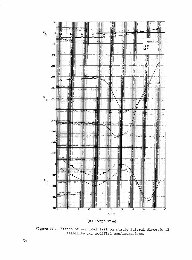
Modified configurations.- The static lateral-directional stability charac-
teristics of the swept- and delta-wing configurations are presented in figure 22
and the characteristics of these configurations are compared with those of the
basic configuration in figure 23. As shown in figure 23, the swept- and delta-
wing configurations had levels of directional stability equal to or higher than
those of the basic configuration, and the trends of Cno at high angles of
attack were dominated by the characteristics of the nose, as previously dis-
cussed for the basic configuration. It should also be noted that the apparent
increase in Cno for the swept- and delta-wing configurations at low angles of
attack was caused by the data-reduction procedure, in which the aerodynamic
characteristics were based on the geometric characteristics of the individual
wings. When compared for equal wing spans, the values of CnP for the0
individual wings are about equal at a = 0-. The relative unimportance of the
large changes in wing planform for the present configuration at high angles of
attack underlines the complexity of flow phenomena and the increased importance
of what might be supposed to be secondary design features, such as fuselage
forebody shape.
The complexity of the situation was emphasized by the results of the force
tests for the high-wing configurations (see fig. 5) as presented in figure 24.
Relocation of the basic wing to a high position (fig. 24(a)) resulted in a
degradation of both Cn and CZ,, whereas relocation of the delta wing to the
high position (fig. 24(b)) resulted in a significant increase in CnP at high
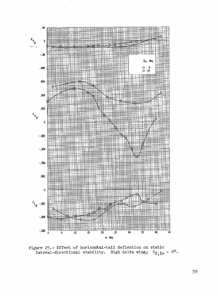
angles of attack for 8h = 0 . Tests to determine the effects of horizontal-
tail deflection for the configuration with the high delta wing indicated a
severe deterioration of CnP due to bh. As shown in figure 25, deflection of
the tail from 8h = 00 to 5h = -250 resulted in extremely unstable values of
Cnp above a = 235 and a reduction in effective dihedral. This result was
probably caused by a change in the vertical location of an adverse flow from the
wing brought about by a change in the load on, and consequently the pressurefield induced by, the horizontal tail.
14

Lateral-Directional Control Characteristics
Basic configuration.- The results of force tests conducted to determine
the control effectiveness of the ailerons and rudder for the basic configura-
tion are presented in figures 26 and 27. The data are presented in terms of
the incremental values of Cy, Cn, and C Z produced by a right-roll or right-
yaw control input. The data of figure 26 show that the incremental rolling
moment produced by aileron deflection for the basic configuration decreased
markedly as wing stall was approached; the ailerons produced relatively small
values of AC2 at post-stall angles of attack. The incremental yawing moments
produced by aileron deflection were favorable (nose-right for right roll input)
except for large control inputs 'a = -30 near stall. In addition, the
favorable values of AC were produced by interference with the vertical tail,n
as shown by the data for 5 = -300 with the tail on and off. These favorablea
yawing moments are unusual for a high-performance fighter and are another
factor producing the known spin resistance of the present configuration.
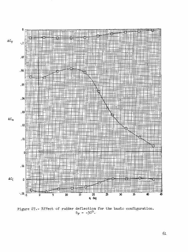
The incremental forces and moments produced by rudder deflection are
presented in figure 27. The rudder was effective for angles of attack up to
wing stall; at higher angles of attack the rudder effectiveness decreased
rapidly. The reduced rudder effectiveness beyond wing stall was associated
with immersion of the vertical tail in the low-energy wake of the stalled wing.
Since this reduction in rudder effectiveness is almost exactly the same as the
reduction in the vertical-tail contribution to Cn shown in figure 16, it is
apparent that the loss in tail contribution to directional stability was caused
primarily by reduced dynamic pressure. It should be noted, however, that the
rudder effectiveness of the present configuration remains quite high to angles
of attack substantially beyond wing stall.
Modified configuration.- The aileron effectiveness for the swept- and
delta-wing configurations is compared with that for the basic configuration in
figure 28. Both the swept and delta configurations exhibited equal or larger
increments of AC 2 at angles of attack above a = 120 than did the basic con-
figuration; however, both wing modifications produced large adverse yawing
moments at and beyond wing stall. These adverse values of ACn would be
expected to degrade the post-stall control of the configuration considerably.
15

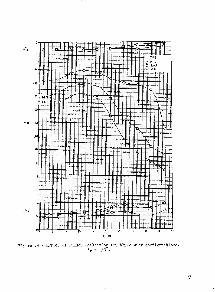
The rudder effectiveness of the various configurations is shown in
figure 29. Although the results for the three configurations were about equal
at a = 00 (when compared for a constant value of b), the swept- and delta-
wing configurations exhibited much higher values of rudder effectiveness at high
angles of attack than did the basic configuration. This result was probably
related to stall patterns on the individual wings and relative location of the
stalled-wing wakes. It should be noted that the reduction in rudder effective-
ness at high angles of attack for these two configurations was much less than
the reduction in vertical-tail contribution to Cnp (see fig. 22). This
indicates, therefore, that the loss of stability was caused by both a loss in
dynamic pressure and an adverse sidewash at the tail.
Dynamic Stability Derivatives
Basic configuration.- The results of the forced-oscillation tests in pitch
for the basic configuration are presented in figure 30. The data show that the
model had stable values of damping in pitch (negative values of Cmq + Cm)over the range of angle of attack and that the contribution of the horizontal
tail to Cmq + Cm6 remained about constant over the range of angle of attack.
The results of the forced-oscillation tests in roll are presented in figure 31.
The damping-in-roll parameter CZp + CZ sin a was stable (negative) for angles
of attack up to 27 , and unstable values were measured for values of a between
270 and 43c . The vertical tail had little effect on the damping-in-roll param-
eter, as might be expected. The results of the forced-oscillation tests in yaw
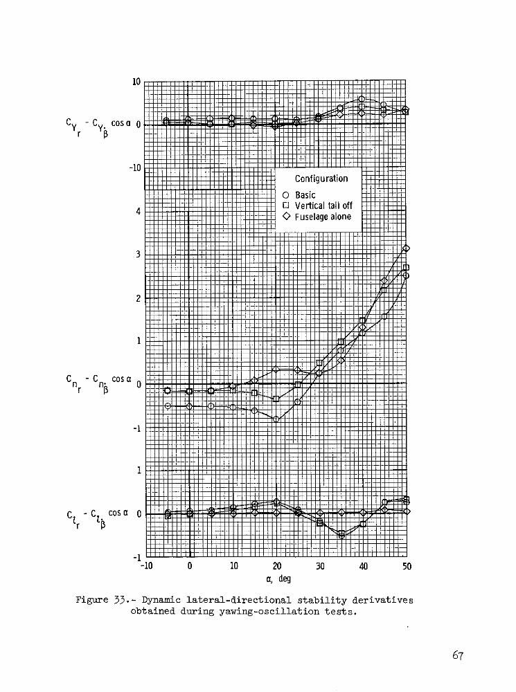
are presented in figures 32 and 33. As shown in figure 32, the damping-in-yaw
parameter Cnr - Cn, cos a was stable (negative) at angles of attack below stall
but became unstable near a = 280 and attained very large unstable values at
higher angles of attack. The vertical tail had little effect on the unstable
values or trends of the data at high angles of attack.
Additional forced-oscillation tests were conducted to determine the cause
of the unstable values of Cnr - Cn cos a at high angles of attack. As shown
in figure 33, positive values of the parameter Cyr - Cy cos a were obtained
with the positive values of Cnr - Cn cos a. This result indicates that the
nose was the principal cause of the unstable values of damping. Evidently, the
16
features of the nose which promoted the beneficial effects on static directional
stability at high angles of attack also produced detrimental effects on dynamic
damping in yaw. The physical cause of the unstable damping in yaw is illus-
trated by the sketches shown in figure 34. In figure 34(a) the configuration
is shown in a steady sideslipped condition with the same value of P at both
the nose and the center of gravity. As pointed out previously, for the present
configuration, the nose produced a side force which acted through a relatively
long moment arm to create a stabilizing yawing moment that tended to reduce the
value of p. The sketch in figure 34(b) illustrates the situation for yawing
flight, with zero sideslip at the center of gravity. Because the flight path is
curved, the nose of the configuration is subjected to a local sideslip angle
which produces a side force in a manner similar to that for the static situation.
In this case, however, the resulting yawing moment is in a direction which tends
to increase the value of yawing velocity and therefore results in unstable
values or Cnr
Modified configuration.- The results of the forced-oscillation tests in
pitch for the swept- and delta-wing configurations are compared with the results
for the basic configuration in figure 35. The data show that all configurations
had stable (negative) values of Cmq + Cm over the range of angle of attack,
and that the delta configuration had significantly lower values of damping in
pitch than the swept or basic configuration.
The results of the forced-oscillation tests in roll presented in figure 36
show that values of the damping-in-roll parameter for the swept and delta con-
figurations were larger than those of the basic configuration at moderate angles
of attack, but all configurations exhibited unstable values at angles of attack
between 310 and 420
The results of the damping-in-yaw tests are presented in figure 37. The
data show that the swept and delta configurations, like the basic configuration,
exhibited unstable values of Cnr - Cn cos C at high angles of attack, but
the delta configuration remained stable to a much higher angle of attack than
the basic configuration.
17

RESULTS AND DISCUSSION OF FLIGHT TESTS
A motion-picture film supplement with selected scenes from the free-flight
tests has been prepared and is available on loan. A request form and a descrip-
tion of the film will be found at the back of this paper. For all the free-
flight tests discussed herein, the center of gravity was at 0.18c.
Longitudinal Characteristics
Since the free-flight tests were intended primarily as an investigation of
the lateral-directional characteristics of the model, the pitch damper was
active for all tests and the pitch pilot's task was only to hold the model as
closely as possible in place in the tunnel test section and to make changes in
model trim as necessary. It should be noted, however, that no unusual or unsat-
isfactory characteristics were noted during the tests and the pilot expressed
satisfaction with the stability and control characteristics up to the highest
angles of attack flown.
Lateral-Directional Characteristics
Basic configuration.- During the flight tests it was found that the basic
model without artificial damping in roll or yaw flew smoothly and with little
effort by the pilots up to an angle of attack of about 20 . Above a = 200
there was a slight nose wandering, or directional "looseness," noted by the
lateral-directional pilot. The nose wandering (although small) increased the
pilot effort required to fly the model smoothly. But the pilot was satisfied
with the level of stability and considered that the major cause of the increased
pilot effort was the rapid decrease in lateral-control effectiveness with
increasing angle of attack. (See fig. 26.) At an angle of attack of about 300
the model diverged in yaw against full corrective controls. The yawing motion
at the divergence appeared to be a fairly slow rotation about the Z body axis.
Flight tests were also made with the leading-edge flap deflected 200
Although the lateral response of the model appeared to be better damped near
a = 20 , the results were essentially the same as for the basic configuration0
and the slow divergence still occurred at about a = 50 . The model was flown
18

with the addition of wing-tip fuel tanks with no noticeable effect on the
dynamic stability of the model. Similarly, the use of artificial damping in
roll had no significant effect on the dynamic stability at high angles of
attack.
When the strakes of figure 7 were added to the model, satisfactory flights
were made up to about a = 180. At slightly higher angles of attack, the model
exhibited more serious nose wandering than the basic configuration, and at
a = 235 a very rapid nose slice, or directional divergence, occurred. This
result serves to emphasize the importance of the fuselage forebody on the sta-
bility characteristics of the present configuration at the stall, as illustrated
by the data of figure 19.
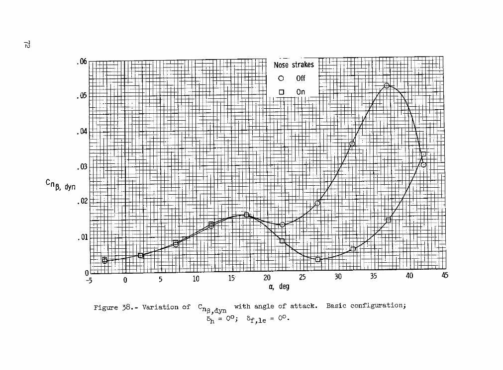
The possibility of directional divergence at high angles of attack is nor-
mally examined by means of the dynamic directional-stability parameter Cno,dyn
(ref. 11), where
IZCn,dyn Cn - C sin
Negative values of Cnp,dyn usually indicate the existence of a direc-
tional divergence. Values of Cnodyn calculated from data of figures 15 and
19 for the basic configuration with and without nose strakes are presented in
figure 38. The parameter Cno,dyn remained positive over the entire angle-of-
attack range and therefore did not predict the directional divergence that was
exhibited in the flight test at a = 235 for the configuration with nose strakes
and at a = 300 for the basic configuration. For the configuration with the
nose strakes, a minimum value of Cno,dyn occurred around a = 27 because of
the unstable (negative) values of Cn at high angles of attack (fig. 19). For
the basic configuration without nose strakes shown in figure 38, Cnp,dyn
increased positively (stable) at the higher angles of attack. It appears,
therefore, that the slow directional divergence exhibited by the model near
a = 300 was not predicted by Cn,dyn but is probably associated with the
unstable values of Cnr - Cn cos a (fig. 32) and the low rudder effectiveness
(fig. 29), neither of which is accounted for in the Cno,dyn criterion.
19

The flights made to determine the effects of various pilot lateral control
techniques at high angles of attack consisted of flying the model with rudder
and ailerons individually and in an interconnected, or coordinated, mode. The
results of these tests showed that flying the model with the rudder alone at
high angles of attack was about as good as using both rudder and ailerons.
When the wing-tip tanks were added and the rudder was used for lateral control,
noticeable rolling motions due to control inputs were obtained, probably
because of the increase in C1, produced by the tanks, as shown in figure 21.
At angles of attack above 10 , the pilot could not use ailerons alone for lat-
eral control because of apparently reduced control effectiveness. Some indica-
tion of the shortcomings of the aileron control at high angles of attack can be
obtained from the aileron-effectiveness parameter (ref. 11) given by
nCCnp - C n -n
Negative values of this parameter indicate roll reversal; that is, a control
input for right roll results in roll to the left. The calculated values of the
parameter for the basic configuration are presented in figure 39, and the
results indicate that roll reversal did not occur. This parameter does have a
minimum value at an angle of attack a few degrees above wing stall, which
occurred around a = 17 . The variations in magnitude of the aileron-
effectiveness parameter are caused by variations in Cno and aileron yawing-
moment characteristics.
Modified configuration.- The swept-wing configuration exhibited dynamic
stability characteristics which were similar to those of the basic configuration.
The model could be flown easily for angles of attack up to about 260. At
slightly higher angles of attack the lateral pilot noted a slight oscillation in
roll ("wing rock"), and at a = 300 the model diverged in yaw against full
corrective control. The rate of divergence was about the same as for the basic
"onfiguration.
During the flight tests it was found that the delta-wing configuration
exhibited the same general flight characteristics as the basic configuration.
20

Slight nose wandering occurred at about a = 20 , and at an angle of attack of
about 350 the model again exhibited the slow divergence in yaw.
The variations of Cndyn for the swept- and delta-wing configurations
are compared with that for the basic configuration in figure 40. The values of
Cnp,dyn were large and positive for all configurations, indicating no direc-
tional divergence, and it therefore appears that the slow divergences observed
during the flights were caused by the unstable values of damping in yaw shown
in figure 37.
When the basic wing was moved to a high position (as in fig. 5), the char-
acteristics of the model were severely degraded. Nose wandering began near
a = 180 and the model exhibited a fairly slow directional divergence near
a = 210. In a similar manner, the high delta-wing configuration also showed
degraded characteristics and a rapid directional divergence near a = 27 . The
variation of Cngdyn for the basic- and delta-wing configurations in the high
position is presented in figure 41. For the high basic wing the possibility of
a mild directional divergence is indicated by a value of CnPdyn of about zero
near a = 220, which is in good agreement with results of the free-flight tests.
The data for the high delta-wing configuration with the elevator deflected 250
show very small positive values of 0Cnp,dyn near a = 52 ; however, the severe
directional divergence near a = 27 which occurred in the flight test was not
inaicated by Cndyn .
The results of the lateral-control tests for all the aforementioned mod-
ified configurations were similar to those for the basic configuration in that
the rudder was the most effective means of roll control at high angles of attack.
It was noted, however, that use of the ailerons appeared to be completely unsat-
isfactory because of noticeable adverse yaw. The degraded aileron effectiveness
for these configurations is illustrated by the variation of the aileron-
effectiveness parameter shown in figure 42. At high angles of attack the swept-
and delta-wing configurations show negative values of the parameter, which
indicate reversal of roll response due to the adverse aileron yaw shown in
figure 28.
21

INTERPRETATION OF RESULTS
The results of the free-flight tests for the basic configuration are in
very good agreement with the characteristics exhibited by the full-scale air-
plane. In particular, within the operational angle-of-attack range, the absence
of any divergence, the good rudder effectiveness, and the absence of adverse yaw
due to ailerons appear to have been adequately represented by the model. Of
course, the low values of Mach and Reynolds numbers associated with the present
tests could cause some characteristics, such as wing stall, to occur at slightly
different angles of attack. In addition, the confined space available within
the wind tunnel, the rapidity of the motions of the model, and the lack of
piloting cues cause the evaluation of lateral-control techniques to be qualita-
tive at best. It appears, however, that the results of the present tests are
indicative of some of the factors which cause the basic configuration to have
outstanding stall and spin characteristics.
It should be pointed out, however, that some of the factors, such as nose
shape, which was found to have a large influence on the stability of the present
configuration at high angles of attack, may be insignificant for other config-
urations. The blending of airframe components for good characteristics at high
angles of attack is very configuration dependent and there are few general con-
clusions to be made. Instead, wind-tunnel test techniques and methods of anal-
ysis similar to those presented herein must be used early in design stages in
order to insure good stall characteristics.
SUMMARY OF RESULTS
The results of a wind-tunnel and free-flight investigation to determine the
factors responsible for the spin-resistant nature of a current fighter airplane
may be summarized as follows:
1. The model exhibited exceptionally good dynamic stability character-
istics for angles of attack substantially beyond wing stall.
2. The configuration was directionally stable over the angle-of-attack
range of the tests. The directional stability was provided by the vertical tail
22

at low and moderate angles of attack and by the fuselage forebody (nose) at
high angles of attack.
3. The wing planform had little effect on the stability characteristics
at high angles of attack.
4. The fuselage forebody produced beneficial contributions to static
directional stability, but it also produced unstable values of damping in yaw.
5. Use of nose strakes located in a position which eliminated the bene-
ficial nose contributions resulted in a severe directional divergence at high
angles of attack.
Langley Research Center,
National Aeronautics and Space Administration,
Hampton, Va., May 23, 1974.
23

REFERENCES
1. Chambers, Joseph R.; and Anglin, Ernie L.: Analysis of Lateral-Directional
Stability Characteristics of a Twin-Jet Fighter Airplane at High Angles
of Attack. NASA TN D-5361, 1969.
2. Mechtly, E. A.: The International System of Units - Physical Constants and
Conversion Factors (Second Revision). NASA SP-7012, 1973.
3. Polhamus, Edward C.; and Spreeman, Kenneth P.: Subsonic Wind-Tunnel Inves-
tigation of the Effect of Fuselage Afteibody on Directional Stability of
Wing-Fuselage Combinations at High Angles of Attack. NACA TN 3896, 1956.
4. Goodman, Alex: Effects of Wing Position and Horizontal-Tail Position on the
Static Stability Characteristics of Models With Unswept and 450 Sweptback
Surfaces With Some Reference to Mutual Interference. NACA TN 2504, 1951.
5. Chambers, Joseph R.; Anglin, Ernie L.; and Bowman, James S., Jr.: Effects
of a Pointed Nose on Spin Characteristics of a Fighter Airplane Model
Including Correlation With Theoretical Calculations. NASA TN D-5921, 1970.
6. Parlett, Lysle P.; and Kirby, Robert H.: Test Techniques Used by NASA for
Investigating Dynamic Stability Characteristics of V/STOL Models.
J. Aircraft, vol. 1, no. 5, Sept.-Oct. 1964, pp. 260-266.
7. Johnson, Joseph L.: Damping in Yaw and Static Directional Stability of a
Canard Airplane Model and of Several Models Having Fuselages of Relatively
Flat Cross Section. NACA RM L50OH3Oa, 1950.
8. Paulson, John W.; and Johnson, Joseph L., Jr.: Free-Flight-Tunnel Investi-
gation of the Low-Speed Stability and Control Characteristics of a Model
Having a Fuselage of Relatively Flat Cross Section. NACA RM L52L22, 1953.
9. Bates, William R.: Static Stabilit of Fuselages Having a Relatively Flat
Cross Section. NACA TN 3429, 1955. (Supersedes NACA RM L9I6a.)
10. Spencer, Bernard, Jr.; and Phillips, W. Pelham: Effects of Cross-Section
Shape on the Low-Speed Aerodynamic Characteristics of a Low-Wave-Drag
Hypersonic Body. NASA TN D-1963, 1963.
11. Moul, Martin T.; and Paulson, John W.: Dynamic Lateral Behavior of High-
Performance Aircraft. NACA RM L58E16, 1958.
24
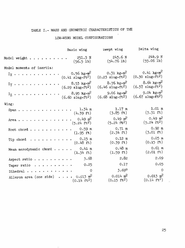
TABLE I.- MASS AND GEOMETRIC CHARACTERISTICS OF THE
LOW-WING MODEL CONFIGURATIONS
Basic wing swept wing Delta wing
Model weight . . . . . . . . . . 251.3 N 243.6 N 244.9 N
(56.5 ib) (54.76 ib) (55.06 lb)
Model moments of inertia:
I X . . . . . . . . ... . 0.56 kg-m2 0.31 kg-m2 0.41 kg-m2
(0.41 slug-ft2 ) (0.23 slug-ft2 ) (0.30 slug-ft2 )
Iy . . . . . . . . . . . . 8.53 kg-m2 8.76.kg-m2 8.64 kg-m2
(6.29 slug-ft2 ) (6.46 slug-ft 2 ) (6.37 slug-ft2 )
I z . . . . . . . . . . . . 8.95 kg-m2 9.06 kg-m2 9.04 kg-m2
(6.60 slug-ft2 ) (6.68 slug-ft2 ) (6.67 slug-ft2 )
Wing:
Span . . . . . . . . . . . . . . 1.34 m 1.17 m 1.01 m
(4.39 ft) (3.85 ft) (3.31 ft)
Area . . . . . . . . . . . . . . 0.49 m2 0.49 m2 0.49 m2
(5.24 ft2 ) (5.24 ft2 ) (5.24 ft2 )
Root chord . . . . . . . . . . . 0.59 m 0.71 m 0.92 m
(1.95 ft) (2.34 ft) (3.01 ft)
Tip chord . . . . . . . . . . . 0.15 m 0.12 m 0.05 m
(0.48 ft) (0.39 ft) (0.15 ft)
Mean aerodynamic chord . .... 0.41 m 0.48 m 0.61 m
(1.34 ft) (1.59 ft) (2.01 ft)
Aspect ratio ..... ...... . 3.68 2.82 2.09
Taper ratio ... . . . . . . . 0.25 0.17 0.05
Dihedral . . . . . . . . . . . . 0 3.690 0
Aileron area (one side) . . . . 0.013 m2 0.014 m2 0.013 m2
(0.14 ft2 ) (0.15 ft 2 ) (0.14 ft2 )
25

TABLE I.- MASS AND GEOMETRIC CHARACTERISTICS OF THE
LOW-WING MODEL CONFIGURATIONS - Concluded
Horizontal tail:
Area .. . . . . . . . . . . . . . . . . . . . . . . . . . . . . . . 0.165 m2
(1.78 ft2 )
Span . . . . . . . . . . . . . . . . .. . . . . . . . . . . . . ... . 0.75 m(2.46 ft)
Aspect ratio (exposed) . . . . . . . . . . . . . . . . . . . . . . . . 2.88
Taper ratio . . . . . . . . . . . . . . . . . . . . . . . . . . . . . 0.33
Dihedral .................. . . . . ............ -4.0
Vertical tail:
Area (exposed) . . . . . . . . . . . . . . . . . . ............ . 0.12 m2
(1.25 ft2 )
Aspect ratio (exposed) . . . . . . . . . . . . . . . . . . . . . . . . 1.22
Taper ratio (exposed . . . . . . . . . . . . . . . . . . . . . . . . . 0.25
Rudder area (aft of hinge) . . . . . . . . . . . . . . . . . . . . . 0.017 m2(0.18 ft2)
Overall fuselage length . . . . . . . . . . . . . . .. ...... . . . 2.38 m(7.81 ft)
26

V
Figure 1.- The body system of axes.
ro

1. 34 _ _ _ 2. 38(4. 39) (7. 81)
Figure 2.- Three-view sketch of basic model. Dimensions are given in m (ft).
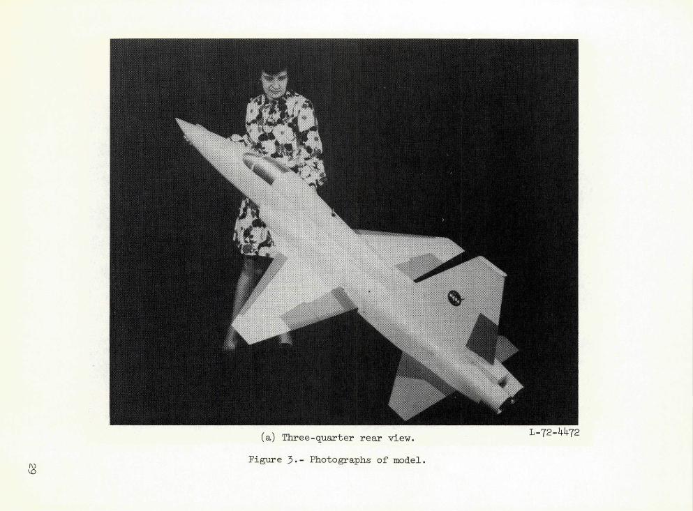
(a) Three-quarter rear view. L-72-4472
Figure 3.- Photographs of model.

0O
(b) Model in free flight.
Figure 3.- Concluded.

L-72-44k7(a) Basic wing with tip tanks.
Figure 4.- Photographs of model with various wings tested.

(b) Swept wing. L-72-4474
Figure 4.- Continued.

(c) Delta wing.
Figure 4.- Concluded.

(a) Basic wing in high position. L-72-8122
Figure 5- Photographs of high-wing models.

(b) Delta wing in high position. L-72-8168
Figure 5.- Concluded.

Delta
Basic
Swept
Figure 6.- Sketch of three wing configurations.
36

B C D
10. 2)
A B C D
A-A B-B C -C D-D
Figure 7.- Sketch of strake position. Dimension given is in cm (in.).
37

Moment reference center
0.75 0.72(2.46) " (2.35)
Figure 8.- Side view of nose alone. Dimensions are given in m (ft).
S PO AND CQNTROL/ CABLE,
SAFETYCABLE
TUNNEL GROUND BOARD
,,AND YAW ' -ILOT ~ PILOTISAFETYT
= CABLEOPERAO
POWEROPERATOR
SPITCHig 9 e f f PILOT
Figure 9.- Setup for free-flight tests.
.5 11ILLl _L
6h, deg0 o
O -101. 4 -17
S -25Off
1.2
1.0
.8
.6
Cg
.2
CD
1.4
-. 17
AX Of
60 10 5 20 2. 30 ... . ..-. .5
u, u C
Figure 10.- Effect of horizontal-tail deflection on static longitudinalcharacteristics of the basic configuration.
41
C.5m O
C .6
.5 Mil 11N
11111 11111 i ll I H il 1111 11
1.6
6f, le' deg
1.2 1-OT ---
1.0.8
eL .6
.4 4 4
.2C D
0 ; I:!'Jill:
-2
-5 0 10 15 20 25 30 35 40 45 .5 0 -.5
a, deg Cm
Figure 11.- Effect of leading-edge flap deflection on static longitudinalcharacteristics of the basic configuration.
41

-] ; I ,;' i
, , iii -'Cm .5
1.711
iitTip tanks
. offniil
41,1i: [] On
.8
16 I ir7
1.4
1.2
LO
.6
.4 T 1-
--
.2
¢D V-
0"
- -
5 0 0 15 20 25 30 35 40 45 .5 0 -.5
j5
a, deg Cm
Figure 12.- Effect of wing-tip tanks on static longitudinalcharacteristics of the basic configuration.
42

0
Cm
.5 6h, deg9
0 oO -10-1.0 0 -17A -25Sonff
1.8
1.6
1.4
1.2
L 0. 8
CL
.6
. 4
CD
-.20
-. 4 20 2 30 35 40 45 .5 0 -. 5 -. Oi
o, deg Cm
(a) Swept wing.
Figure 13.- Variation of static longitudinal characteristics withangle of attack for modified configurations.
4,3

0
Cm
. 5. . . .. . . .
tm--- -- +H44H++f ---
Oh, dego o
-1. 0 -10-17
# - -25S off
L8
1.6
1.4
1.2
1.0
.8
L ------- ----- L
.6
Ism4 # ii H-t
RIN - 4- onlued
.4
.2
CD
0
.2
E
.4 10 15 20 25 30 35 40 45 .5 0 -. 5 -LIY
4 deg Cm
(b) Delta wing.
Figure 13.- Concluded.
44

Cm 0
1.5
-1.0 WingO BasicO SweptC Delta
1.8
1.6
1.4
1.2
1.0
CL .8
.44
.2
-5 0 5 1 15 20 25 30 35 40 45 .5 0 -. 5 -1. 0
a, deg Cm
(a) Horizontal tail on. h = 0
Figure 14.- Variation of static longitudinal characteristics withangle of attack for three wing configurations.

Cm
Wing
O BasicO Swept
SDelta1. 4
.. L
I ,I I II I I l , , , l i , ,
C iql l=ll64l
CD 0
/ -] 9 ! !! l l II == : L] : l ! ! l ] i l ! ! i[ i w
,,, '~ ~ ... ... .. . .. . .. . ,i1 v -.
45 0 5 10 15 20 25 30 35 40 45 5 0
a, deg Cm
(b) Horizontal tail off.
Figure 14.- Concluded.
46
g t, !b 4 t il il ,li, ........
. .. ....! 1 , : ,.8 ~ ~ -t ! ~j # , !/ ' ,,i ,iLi...
t T:;G III!I!!,,!,~ ~~~ i i , .. . . . 1t1, t + I I
I l l ! ! ! :1.0 ; I : ! I ; -I / [ Ii .. . . .. . . i l lI l
!; i . ' '' l ll l . .. . . ,, IIM, i , , . .!... . ~ ~ ~ ~ ~ ~ -i T .. i# l #: i lllll!lllll ll~l
C .8 1 ~ l , ! l l ~ ! : ; ' ' ' ' ' ' : ]-'' -' . . .. . ' " I I I i ' " .
I t 1 1 1 ! .... . . . . 1 1 .. . . . . . . I . . .
.2~ I ...... .. ... ... I.!! .1 1 1 1 1 1, ..C1 #, III I l l lD l F#/L 7# } L -ll+ l+ ~ l I~lll llllg
.2 i i! ...... .... . I ii .C + l ii i l II I ll l !! l ll ! !4 IP T, ... .# ~14 i Hllf
-. 2lJ 1 .i; 1 Ilitl l ]l l l f!tl i l 1
-5 0 . . . . . . . . .5 10 .. . .. . .. . . I20II I!301 15 11 4..... ... ... . . . .5lk ~ l l lo o . ... . , , a, .. ... . .. ... . CI I mI, ~ t ... ...
0~ ~ ~ ~ ~ b Horizontal .. . ... . off. I! .... llll ll
~ ~ ~~ ~Fgr 4 Cn lied. ll~l ¢ll~lllll
4 6. . . .i l . . . . . . . . . . . . i ; . . . . . .II . . . . .

C0o 1 i ,i 1:i i Ii -i ! jt/ ii i
rjl I F 11 'lli'Iti: 1h, 1 e
-£ I¢ [ l -17
.006 .ili ~ ~ I- i
.004 1 rn
t
002 !
1' I i i; -i !
(t~.t-~;~; ~ t ;I
i - i i l/-.o +.ii
44!44
,. i- , i-. 002 i ,, I, i i ...it , . ... i~i
J_ I' ~ jiIP i i 'i I
.iit
i-.. II -+l
i!! ....71 47
71 ITI- ii 'ti
H F;-. 002~
i I iir I-T i +Ti-5 0 5 10i 15 20 2 30 3 40 4
I I1:tla, deg
Fiue15-Efeto orznalti efetono tai aerldretoastbiiy. Bsi cnigrtin; b ,e 0
jlli I -i i47

.05 1H On
Off.0
.050 -- -- 0 O
;it q 1
. 0084 H -f
'j-1
T7-1 1 i
. 006
I I I ; 1C jIii
-.002
+ 1. te oroae
stabIil fo bai ofiuain
f T
T 1 I It Ii 7
Hii
-.002 i::1 k it :i0 + IMMICi i I
-. M)6 i I I ~~~1 ::t
iri-.006
stailiy fr bsi cofigraton
48Li ,

.05 - F.
T F ITI
-.0
0 Ve icaltailoff
!r i Nose alone
'r
Tm.
.054 -----
[lit
- -- -t 4 l 1 Nsealn
],
i
ttI I t
-. oo2 iii.004 i ;
-.® 6 i .i
Tf ,
iii'CnI A
-. 004 tj
.4-,
-5~~ 0I 5 I0 15 2 5 30 3 0
W, d
-.00 77,~~f-~-~~I
Figre 7. Vaiatonof ti c lerl-d1: iiirt ia character'' istic
wit veriHa tail L!.
'4' T 17
ih.006
-5 5 10 15 0 5 0 3 4 4
with vertical tail off
iii il; li49

0
S= 10 = = -Io
Figure 18.- Variation of oil-flow patterns on the nose with angle of sideslip. a = 400

-.05 Nos ]slIraIkes;
Effi IO41
.0
MIR4
-.05 7 ------ # Nose strakes
-. ff
I Ii On.006 V7
-.-7
:t i, , de
41- -
151
.002 i
C lit, r t I ~ i
..002 Ly
4 H ii !
.00i i J -Id I ff I 44 J!! L
-.006 1.11I J'e t; - 1 i
t K ij I i -1iJ-T - . _i t 11: '0 flI
t Nti ~!~#l-. 002 I
-.004 i- I -ili
-5 0 5 10 15 20 25 30 35 40 45a, deg
Figuree 19,- Effect of nose strakes on static lateral-directional stability.
Basic configuration; 5h = 0; bfle = 00.
51

I I : r
7 4_
C
-.051h ' l
Sf, le, degI li , IO
. nJpI6 i i i 0.006 24
"IL lJ t ill !IIT!~~ ,t! 1kL i il ij i L
.004 f 141
i I ii i 1
n .002
0 -
r I T ll l
- i " -£ itt i -
-.002 - a i
o
Ffi ! ~ I H +
7- 41 ~ .. 4+ +4-- --1-
- ,' t i. . . ... I l
i .. .
-.002 :C j
-. 004t -H 1 1 Ilk 14 ,
-5 0 5 10 15 20 25 30 5 40 45
a, deg
Figure 20.- Effect of leading-edge flap deflection on static
lateral-directional stability for basic configuration.
52

.0
CY 0Y0 -- ----- ---- -- - - * - * - *** * ** * *: ** *
-. 5 05 10 15 0 5-3 3 O offO On
.006
C- -002- -
T-.i 002t
---- - --- ........- --------- - --
Tti II --- ----.002- 0 10 1 20 25 30 35 40 5
a, deg
Figure 21.- Effect of wing-tip tanks on static lateral-directionalstability for basic configuration.
53
Vertical tail-. 05 !
0 Off
.010 I
.008. i
.002
C
00 5 0 15 20 25 30 35 40 45
(a) Swept wing.
.004 --
Figure 22.- Effect of vertical tail on static lateral-directional
501
-Ta
004
54

.008
I I
.004
Cn .002
-. 002
-.004
.006
.002
Clp -. 002
a, deg
(b) Delta wing.
Figure 22.- Concluded.
55

.05 -
C IT
-o 05
Wing
1-1 i i T.
O Basic
.006
.004
------- - -4
0-
-.002
- -.004 -----
----- - - - - - ---
-008-5 0 5 10 15 20 25 30 35 40 45
a, deg
Figure 23.- Variation of static lateral-directional stability withangle of attack for three wing configurations.
56

.05"S -----------
cY 0 -------------
S05
CYA
-.05Wing
O BasicO High basic
.006
.004
Cn .002
-.002
0TI
-.006 5 5 10 15 20 25 30 35 40 45
a, deg
(a) Basic wing.
Figure 24.- Effect of wing position on static
lateral-directional stability.
57

.006
C
nWing
(b)O D wDelta
.002.002
C- -- 002
.004
.002CZ-- ------
-" 0 05 10 15 20 25 30 35 40 4
a, deg
(b) Delta wing.
Figure 24.- Concluded.
.05
Y 0
-. 05
.008
.006
.004
. 002
C
0
-.002
.006
•002
-- .0- - -
Figure 25.- Effect of horizontal-tail def
lateral-directional stability. High d

.2
ACy 0
-. 2
.01
AC, 0
.01
Vertical tail 6,, deg
.05 0 On -30
[ Off -30A0 On -15
.03
. 02
AC. .01
0
-5 0 5 10 15 20 25 30 35 40 45
a, deg
Figure 26.- Effect of aileron deflection for the basic configuration.
60
0
ACY-. 2
.07
.06
.05
.04
.03
^Cn
.02
.01
.01
CZ 0S. . .. . .
--. -- -20 3 0 35 40 45
4 dy
Figure 27.- Effect of rudder deflection for the basic configuration." = -304 .
61

O BasicO7 SweptO Delta
.01
ACn 0
-.01
.03 KF1
.02
eAC01 I Delt
0- 5 1 1 2 25 30 35 40 4
a, deg
Figure 28.- Effect of aileron deflection for three wing configurations.
Ba = -150.
62
.01
0
Swp
~C, (leg
.0 .......-----
.0
J, +14" IT
,&Cn .04 0

Ht L -'
CNq + CNa ,ii. [
q l Hr II i
:iF ! " 14- h, deg
il-1 ril- H I- ;IF
I hIll 1- I 1 Il, 1 ! 16,, d10 02 ~i I " UI I Off
2 1 fill i-ii-
0I it lC C Hit i T lqA Aa Y;IH1 r
S; Ii .. .. i
-2 .77 . t!C A + A '!k I i 1; Iti~~mIi
i i i ll , 11
Si ld
iti
i L] i -, .t i ttj
-:It P !,1-I II fi l.. ..r.. , J' T
11 1 t I
-i i~ -d I. _ ii
Cm +C -1 -- ii ' i i i r;1
i ilr i-; i !-
Ii
r It-It :Fit 1- f, ll i 11 I 4
-i !:o -I ! i !- ,,I10 0 10 20 30 40 50
oi deg
Figure 30.- Effect of horizontal tail on dynamiclongitudinal-stability derivatives obtainedduring pitching-oscillation tests. Basic con-figuration; bf le = 00 .
64

Cyp *Cy sina 0a5
C +C sin a 0 k*
-5Vertical tail
O On.5 1 O Off
C + C sin a 0n n
-,
-.5
-1. k
-1. 5
-2.0
1.0
C + C sin a 0
.5
- 010 0 10 20 30 40 50
a, deg
Figure 31.- Effect of vertical tail on dynamiclateral-directional stability derivativesobtained during rolling-oscillation tests.
65

10-- -- - - - - -
C - C cos a ----------r B 0
Vertical tail3
© On- - Off
t - 0 4 - -
-. 1
.1
C - C cos a
n n 0r b --
.1 - - - -- l ----
-. 1
-10 0 10 20 30 40 50a, deg
Figure 32.- Effect of vertical tail on dynamic lateral-directional stabilityderivatives obtained during yawing-oscillation tests.
66
10 I I I II i ,
C C cos a 0
-10Config u ration
O Basico Vertical tail offO Fuselage alone
C - C cos ar 0
-1
C- C cos a 0tir B
-1-10 0 10 20 30 40 50
a, deg
Figure 35.- Dynamic lateral-directional stability derivativesobtained during yawing-oscillation tests.
67

(a) Static, p f 00. (b) Yawing, 0 = 6 .
Figure 34.- Illustration of cause of unstable values of damping in yaw.
68

i(j I - xtiI I W
27 iF _-
C + C
q a --
2 -Wing
-4 . - - - -. . .
10 0F l i l sa blit d
v n ui I t h gI lai ts
10
o r th w1 '
-0 O 20 0 60 50
Sa69
-2-
-4
0
69

CYp CC sina 0
-10Wing
O BasicO Swept
5 0 Delta
Cnp Cn sina 0
-. 5
-1.0
-1.5
-2.0
-2.5
-3.0
-3.5
L5
1.0
.5
Cp +Cl sina 0
-LO
a, deg
Figure 36.- Dynamic lateral-directional stabilityderivatives obtained during rolling-oscillationtests for three wing configurations.
70

20
10
Wing
O BasicO Swept
5 0< Delta
----------O S a
C -C cos a
-1
-10 0 10 20 30 40 50a, deg
Figure 37.- Dynamic lateral-directional stabilityderivatives obtained during yawing-oscillationtests for three wing configurations.
71
-2
--- 44 eg
Fiue5.- yai aerldrcinaVtbltdeiaie obtine duingyaingoscllaio
tetsfo t~rewig onigrtios
+H+ _+ 4+ 771
.06 FT TT!, TII-H Nose strake
O Off-T_71 Ll -F I On - lTT I lI
.05 0 O
.04
.03
Cn !]1d yn
.02
I I ..... ..... I L L I k
.01
-50 5 10 15~ 20 25 30 3 04a, deg
Figure 58.- Variation of C~dn with ange of attac. Basic configuration
- - -= 00 L _j = 00II
.... IL TT-I P hL
7i] IIII LLTT -
-t-H- +I- L5 Li 15 20 25 30 L5 40
IZL =- OO. -fl = Oo

.010
.009
.008
. 007
. 006
.005
o .004
.003
.002
.001 -5 0 5 10 15 20 25 30 35 40 45
a, deg
Figure j9.- Variation of aileron-effectiveness parameter with angleof attack. Basic configuration; Bh =00.
73
005l ll l If I 1
IL I) 1 1 f i l l I l l l , , ,
.003 I+I H . .,, , .. . .'" " . .11!111 .. .. ... ."4+"- -"
.0 0 I I l q ll l 1 ll l ll H i l l l
0-5 0 5 10 15 20 dg25 30 35 40 45
Figure 39.- Variation of aileron-effectiveness parameter with angle
of attack. Basic configuration; &h = 0 0.
73

. 13 I 1 1III I
.12
.11
Wing.10 0 : O Basic
O SweptO Delta
.09
.08
.07
.06
n0 , dyn
.05
.04
.03
.02
.01
0-5 0 5 10 15 20 25 30 35 40 45
a, deg
Figure 40.- Effect of wings on variation of Cn ,dyn with angle of attack.
74

l3, dyn 0
Wn.04g fd He+ de
t ti
.01 e
,, High basic 0
O High delta 0
-.02 < ' I ' High delta -25
03 --------- --- - -------- - -
.03
0 5 10 15 20 25 30 35 40 45
a, deg
Figure 41.- Variation of Cdy n with angle of attack for high-wing configurations.

.010 ,
.009.
Wing
.008. O Basico Swept0 Delta
.007
.006
r-rS .005
.004
.003
- 0-02H.-5 0 5 10 15 20 25 30 35 40 4
.0023... I'1 ' I A I I [ I I I l
a, deg
6 NASA-Langley 1974 L-96
I Irl i -I I I I I I -
.001 i Ii l I lil L II
angleIRIIIIIIII ofatckfrtheIinIofiuaios]h 0
76 NASA-Langley, 197 1-q~