Embed Size (px)
Citation preview
i
NATIONALBUREAU OF STANDARDS
The program of research on building materials and structures, carried on by the
National Bureau of Standards, was undertaken with the assistance of the Central Hous-
iug Committee, an informal organization of governmental agencies concerned with
housing construction and finance, which is cooperating in the investigations through a
subcommittee of principal technical assistants.
CENTRAL HOUSING COMMITTEESUBCOMMITTEE ON TECHNICAL RESEARCH
Walter Junge, Chairman. A. C. Shire, Vice Chairman.
Federal Housing Administration. United States Housing Authority.
Sterling R. March, Secretary
Albert G. Bear,
Veterans' Administration.
Pierre Blouke,Federal Home Loan Bank Board (Fed-
eral Loan Agency).
Carroll W. Chamberlain,
Public Buildings Administration (Fed-
eral Works Agency).
Joseph M. DallaValle,Public Health Service (Federal Security
Agency).
John Donovan,Farm Security Administration (Agri-
culture).
George E. Knox,
Yards and Docks (Navy).
Vincent B. Phelan,
National Bureau of Standards (Com-
merce).
Edward A. Poynton,
Office of Indian Affairs (Interior).
George W. Trayer,
Forest Service (Agriculture),
Elsmere J. Walters,
Construction Division (War).
CHAIRMEN OF SECTIONS
Specifications Materials Maintenance
Carroll W. Chamberlain Elsmere J. Walters John H. Schaefer
Mechanical Equipment Methods and Practices
Robert K. Thulman
NATIONAL BUREAU OF STANDARDSSTAFF COMMITTEE ON ADMINISTRATION AND COORDINATION
Hugh L. Dryden, Chairman.
Mechanics and Sound.
Phaon H. Bates, Gustav E. F, Lundell,
Clay and Silicate Products. Chemistry.
Hobart C. Dickinson, Addams S. McAllister,
Heat and Power. Codes and Specifications.
Warren E. Emley, Henry S. Rawdon,
Organic and Fibrous Materials. Metallurgy.
The Forest Products Laboratory of the United States Department of Agriculture is
cooperating with both committees on investigations of wood constructions.
[For list of BMS publications and how to purchase, see cover page III.]
UNITED STATES DEPARTMENT OF COMMERCE • Harry Hopkins, Secretary
NATIONAL BUREAU OF STANDARDS • Lyman J. Briggs, Director
BUILDING MATERIALS
a7id STRUCTURESREPORT BMS36
Structural Properties oi Wood-Frame Wall, Partition, Floor, and
Rool Constructions with "Red Stripe" Lath Sponsored by
The Weston Paper and Manufacturing Co.
by HERBERT L. WHITTEMORE and AMBROSE H. STANG
with the collaboration of
Thomas R. C. Wilson
Forest Products Laboratory
Forest Service, United States Department of Agriculture
ISSUED JANUARY 2, 1940
The National Bureau of Standards is a fact-finding organization;
it does not "approve" any particular material or method of con-
struction. The technical findings in this series of reports are to
be construed accordingly.
UNITED STATES GOVERNMENT PRINTING OFFICE • WASHINGTON - I 9 4O
FOR SALE BY THE SUPERINTENDENT OF DOCUMENTS, WASHINGTON, D. C. • PRICE lO CENTS
ForewordThis report is one of a series issued by the National Bureau of Standards on the
structural properties of constructions intended for low-cost houses and apartments.
Practically all of these constructions were sponsored by groups within the buUding industry
wliich advocate and promote the use of such constructions and which have built and
submitted representative specimens as outlined in report BMS2, Methods of Deter-
mining the Structural Properties of Low-Cost House Constructions. The sponsor,
therefore, is responsible for the description of the specimens and the method of fabrication.
The Bureau is responsible for the method of testing and the test data.
Tills report covers only the load-deformation relations and strength of the structural
elements when subjected to compressive, transverse, concentrated, impact, and racking
loads by standardized methods simulating the loads to wliich the elements would be
subjected in actual service. It may be feasible later to determine the heat transmission
at ordinary temperatures and the fire resistance of these same constructions.
The Forest Products Laboratory, Forest Service, United States Department of
Agriculture, collaborated in the tests of constructions having wood structural members.
The National Bureau of Standards does not "approve" a construction, nor does it
express an opinion as to the merits of a construction, for the reasons given in reports
BMSl and BMS2. The teclmical facts presented in tliis series provide the basic data
from wluch arcliitects and engineers can determine whether a construction meets desired
performance requirements.
Lyman J. Briggs, Director.
Structural Properties of Wood-Frame Wall, Partition, Floor,
and Roof Constructions with "Red Stripe" Lath Sponsored
by The Weston Paper and Manufacturing Co.
by HERBERT L. WHITTEMORE and AMBROSE H. STANG
with the collaboration of Thomas R. C. Wilson, Forest Products Laboratory, Forest
Service, United States Department of Agriculture
CONTENTSPage
n2
Foreword
I. Introduction
II. Sponsor and product 2
III. Specimens and tests
IV. Materials-.,
3.
10.
Sources of information
Wood(a) Framing for walls and parti-
tions
Framing for floors and roofs, _
Sheathing and subflooring
Bevel siding
(b)
(c)
(d)
(e)
(f)
(g)
Bridging 4
Flooring 4
Spacers and grounds 4
"Red Stripe " lath 6
(a) Description 6
(b) Physical properties 7
Nails_.-_" 7
Plaster 7
Sheathing paper 9
Tacks 9
Size 9
Paints 9
(a) Outside 9
(b) Inside 9
Shellac varnish 9
Page
IV. Materials—Continued.
11. Roofing 9
(a) Asphalt 9
(b) Caps 9
V. Wall BQ 9
1. Description, sponsor's statement 9
(a) Four-foot wall specimens 9
(b) Eight-foot wall specimens 10
2. Compressive load 11
3. Transverse load 12
4. Concentrated load 13
5. Impact load 14
6. Racking load 15
VI. Partition BR 16
1. Description, sponsor's statement 16
2. Concentrated load 17
3. Impact load_ 18
VII. Floor BS 19
1. Description, sponsor's statement __ 19
2. Transverse load 21
3. Concentrated load 21
4. Impact load 21
VIII. Roof BT 21
1. Description, sponsor's statement 21
2. Transverse load_„ 24
3. Concentrated load 25
IX. Comments by sponsor 25
1 j
ABSTRACT
For the program on the determination of the struc-
tural properties of low-cost house constructions, The
Weston Paper and Manufacturing Co. submitted 30
specimens representing wood-frame wall, partition,
floor, and roof constructions with "Red Stripe" lath.
The wall specimens were subjected to compressive,
transverse, concentrated, impact, and racking loads;
the partition specimens to concentrated and impact
loads; the floor specimens to transverse, concentrated,
and impact loads; and the roof specimens to transverse
and concentrated loads. For each of the loads three
like specimens were tested. The transverse, concen-
trated, and impact loads were applied to both faces of
the wall specimens, and for each of these loads six like
specimens were tested. The deformation under load
and the set after the load was removed were measured
for uniform increments of load, except for concentrated
loads, for which the set only was determined. The
results are presented in graphs and in tables.
I. INTRODUCTION
To provide technical facts on the performance
of constructions wliich might be used in low-
cost houses, to discover promising new con-
structions, and ultimately to determine the
properties necessary for acceptable performance
in actual service, the National Bureau of
Standards has invited the cooperation of the
building industry in a program of research on
building materials and structures suitable for
low-cost houses and apartments. The objec-
tives of this program are described in report
BMSl, Research on Building Materials and
Structures for Use in Low-Cost Housing, and
that part of the program relating to structural
properties in report BMS2, Methods of Deter-
mining the Structural Properties of Low-Cost
House Constructions.
Masonry constructions and wood construc-
tions of types which have been extensively used
in this country for houses were included in the
program because their behavior under widely
different service conditions is known to builders
and the public. The reports on these con-
structions are BMS5, Structural Properties of
Six Masonry Wall Constructions, and BMS25,Structural Properties of Conventional Wood-Frame Constructions for Walls, Partitions,
Floors, and Roofs. The masomy specimens
were built by the Masonry Construction Sec-
tion of this Bureau, and the wood-frame speci-
mens were built and tested by the Forest
Products Laboratory at Madison, Wis.
The present report describes the structural
properties of constructions sponsored by one of
the manufacturers in the building industry.
The specimens were subjected to compressive,
transverse, concentrated, impact, and racking
loads, simulating loads to which the elements of
a house are subjected. In actual service, com-pressive loads on a wall are produced by the
weight of the roof, by second floor and second-
story walls, if any, by furniture and occupants,
and by snow and wind loads on the roof.
Transverse loads on a wall are produced by the
wind, concentrated loads by furniture or acci-
dental contact with heavy objects, and racking
loads by the action of the wind on adjoining
walls. On nonload-bearing partitions, impact
loads may be applied accidentally by furniture
or by a person falling against a partition, andconcentrated loads by furniture or by a ladder
or other object leaning against a partition.
Transverse loads are applied to floors by furni-
ture and by the occupants; concentrated loads
by furniture, for example, the legs of a piano;
and impact loads by objects falling on the floor
or by persons jumping on the floor. Transverse
loads are applied to roofs by wind and snow;
concentrated loads by persons walking on the
roof and by tools and equipment when the roof
is constructed and repaired.
The deflection and set under each increment
of load were measured because, considered as a
structure, the suitability of a construction de-
pends not only on its resistance to deformation
when loads are applied, but also on whether it
returns to its original size and shape when the
loads are removed.
II. SPONSOR AND PRODUCT
The specimens were submitted by TheWeston Paper and Manufacturing Co., Dayton,
Ohio, and represented wood-frame construc-
tions with a fabricated paper-stock lath mark-
eted under the trade name "Red Stripe." Theconstructions consisted of conventional wood-frame walls, partitions, floors, and roofs, with
lath and plaster as one or both faces.
[2]
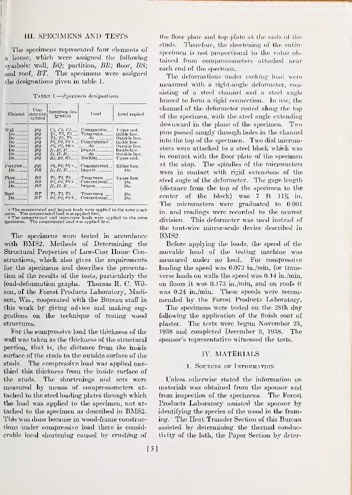
III. SPECIMENS AND TESTS
The specimens represented four elements of
a house, which were assigned the following
symbols: wall, BQ; partition, BR; floor, BS;
and roof, BT. The specimens were assigned
the designations given in table 1
.
Tabls 1.
—
Specimen designations
Element
IV all
DoDoDoDoDoDoDo
PartitionDo
FloorDoDo
RoofDo
Con-structionsymbol
BQBQBQBQBQBQBQBQ
BRBR
BSBSBS
BTBT
Specimen des-ignation
C/, C2, C3..T1, T2, T3--Tlf, T.5, T6.^PI, P2, PS »_
Pi, P5, P6It, It, IS
U, IS, leR1,R2,R3_..
PI, P2, PS »_
It, 12, IS
Tl, T2, TS...Pt,P2,PSII, 12, JS.__.
Tl, T2, TS.__P1,P2,PS
Load Load applied
Compressive...Transverse
doConcentrated _
.
doImpact
do._ _.
Racking
Concentrated.Impact
TransverseConcentrated.Impact...
TransverseConcentrated.
Upper end.Inside face
.
Outside face.
Inside face
.
Outside face.
Inside face.
Outside face.
Upper end.
Either face.
Do.
Upper face.
Do.Do.
Do.Do.
» The concentrated and impact loads were applied to the same speci-mens. The concentrated load was applied first.
^ The concentrated and transverse loads were applied to the samespecimens. The concentrated load was applied first.
The specimens were tested in accordance
with BMS2, Methods of Determining the
Structural Properties of Low-Cost House Con-structions, which also gives the requirements
for the specimens and describes the presenta-
tion of the results of the tests, particularly the
load-deformation graphs. Thomas R. C. Wil-
son, of the Forest Products Laboratory, Madi-son, Wis., cooperated with the Bureau stafl^ in
this work by giving advice and making sug-
gestions on the teclmique of testing woodstructures.
For the compressive load the tliickness of the
wall was taken as the thickness of the structural
portion, that is, the distance from the inside
surface of the studs to the outside surface of the
studs. The compressive load was applied one-
third this thickness from the inside surface of
the studs. The shortenings and sets were
measured by means of compressometers at-
tached to the steel loading plates through which
the load was applied to the specimen, not at-
tached to the specimen as described in BMS2.Tliis was done because in wood-frame construc-
tions imder compressive load there is consid-
erable local shortening caused by crushing of
the floor plate and top plate at the eiuls of the
studs. Therefore, the short(!ning of the entire
specimen is not proportional to the vnlnc ob-
tained from compressometers attached near
each end of the specimen.
The deformations under racking load were
measured with a right-angle defoi-metcr, con-
sisting of a steel channel and a steel angle
braced to form a rigid connection. In use, the
channel of the deformeter rested along the top
of the specimen, with the steel angle extending
downward in the plane of the specimen. Twopins passed snugly through holes in the channel
into the top of the specimen. Two dial microm-
eters were attached to a steel block which wasin contact with the floor plate of the specimen
at the stop. The spindles of the micrometers
were in contact with rigid extensions of the
steel angle of the deformeter. The gage length
(distance from the top of the specimen to the
center of the block) was 7 ft 11^ in.
The micrometers were graduated to 0.001
in. and readings were recorded to the nearest
division. This deformeter was used instead of
the taut-wire mirror-scale device described in
BMS2.Before applying the loads, the speed of the
movable head of the testing macliine was
measured under no load. For compressive
loading the speed was 0.072 in./min, for trans-
verse loads on walls the speed was 0.14 in./min,
on floors it was 0.173 in./min, and on roofs it
was 0.24 in./min. These speeds were recom-
mended by the Forest Products Laboratory.
The specimens were tested on the 28th day
foUowmg the application of the finish coat of
plaster. The tests were begun November 23,
1938 and completed December 9, 1938. Thesponsor's representative witnessed the tests.
IV. MATERIALS
1. Sources of Information
Unless otherwise stated the information onmaterials was obtained from the sponsor and
from inspection of the specimens. The Forest
Products Laboratory assisted the sponsor byidentifying the species of the wood in the fram-
ing. The Heat Transfer Section of tliis Bureauassisted by determining the thermal conduc-
tivity of the lath, the Paper Section by deter-
[3]
milling tlie other physical properties of the
lath, and the Lime and Gypsum Section by
determining the properties of the plaster.
2. Wood
(a) Framing for Walls and Partitions
Studs, floor plates, top plates, and girts,
Douglas-fir, Pseudotsuga taxijolia, No. 1 com-
mon, S4S (surfaced four sides), 1^^ by 3% in.
(nominal 2 by 4 in.).
(b) Framing for Floors and Roofs
Joists, rafters, and end members, longleaf-
southern-pme, identified as southern yellow
pine, Pinus sp., No. 1 common, S4S, Ifs by 7^ in.
(nominal 2 by 8 in.).
(c) Sheathing and Subflooring
Shortleaf-southern-pine, Pinus sp., No. 2 com-
mon, dressed and matched, tongued-and-
grooved, in. thick by 5}i in. face width
(nominal 1 by 6 in.).
(d) Bevel Siding
Red-cypress, Taxodium distichum, select, grade
C or better, by %6 by 5^2 in.
(e) Bridging
Shortleaf-southern-pine, Pinus sp., No. 2
common, rough, 1 by 3 in.
(/) Flooring
White-oak, Quercus sp., plain-sawed, clear,
tongued-and-grooved, end-matched, ^^ein. thick
by 2% in. face width, Jackson Lumber Co.'s
"Merit Brand."
(g) Spacers and Grounds
Shortleaf-southern-pine, Pinus sp., No. 2
common, S4S. Spacers for walls and partitions
were by 3% in. (nominal 1 by 4 in.), andfor floors and roofs ^5^2 by 6'^%2 in. (nominal1 in. tliick). Grounds were by 1% in.
(nominal 1 by 2 in.).
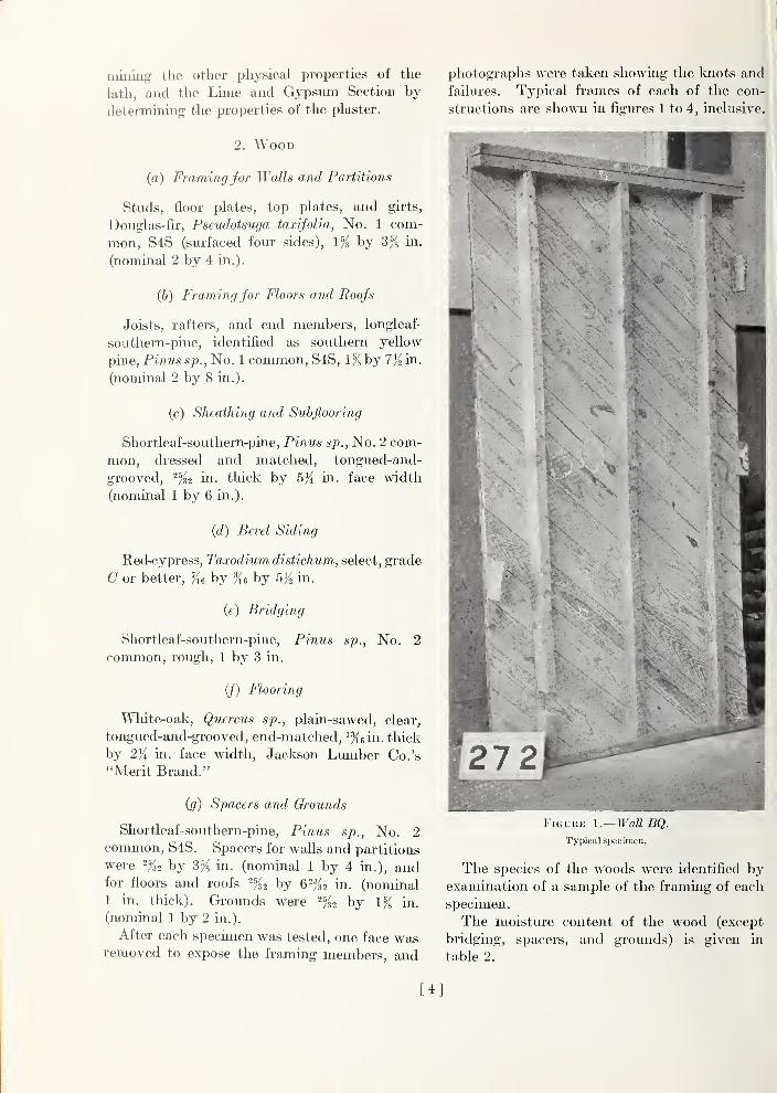
After each specimen was tested, one face wasremoved to expose the framing members, and
photographs were taken showing the knots and
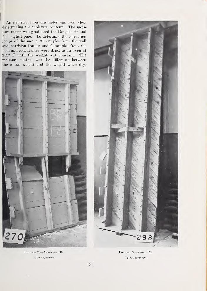
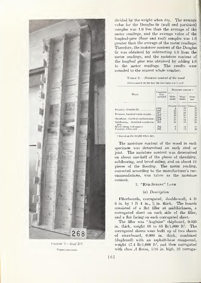
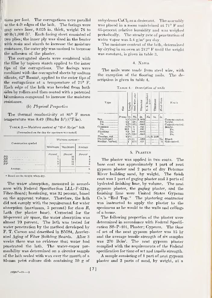
failures. Typical frames of each of the con-
structions are shown in figures 1 to 4, inclusive.
Figure 1. Wall BQ.
Typical specimen.
The species of the woods were identified byexamination of a sample of the framing of each
specimen.
The moisture content of the wood (except
bridging, spacers, and grounds) is given in
table 2.
[4]
An electrical moisture meter was used whendetermining the moisture content. The mois-
ture meter was graduated for Douglas fir and
for longleaf pine. To determine the correction
factor of the meter, 21 samples from the wall
and partition frames and 9 samples from the
floor and roof frames were dried in an oven at
212° F until the weight was constant. Themoisture content was the difference between
the initial weight and the weight when dry,
Figure 2.
—
Partition BR.
Typical specimen.
Figure Z.—Floor BS.
Typical specimen.
[5]
divided by the weight when dry. The average
value for the Douglas fir (wall and partition)
samples was 1.0 less than the average of the
meter readings, and the average value of the
longleaf-pine (floor and roof) samples was 1.0
greater than the average of the meter readings.
Therefore, the moisture content of the Douglas
fir was obtained by subtracting 1.0 from the
meter readings, and the moisture content of
the longleaf pine was obtained by adding 1.0
to the meter readings. The results were
rounded to the nearest whole number.
Table 2.
—
Moisture content of the wood
IDetermined on the day the specimen was testcdl
Wood
Framing, Douglas fir
Framing, longieaf-southern-pine . .
.
Sheathing, shortleaf-southern-pine
Subflooring, shortleaf-southern-pine.
Bevel siding, red-cypressFlooring, white-oak
Construc-tion
symbol
(BQ\BRIBS.\bt(BQ\BTBS.
BQ.BS.
Moisture content
'
Mini-mum
Percent912
12
13
12
17Ifi
Maxi-mum
Percent2318
252,5
19
24
23
13
13
Aver-age
PercentI.')
15
19
19
16
20
19
n10
Figure 4.—RoofBT.
Typical specimen.
a Based on the weight when dry.
The moisture content of the wood in each
specimen was determined on each stud or
joist. The moisture content was determined
on about one-half of the pieces of sheathing,
subflooring, and bevel siding, and on about 10
pieces of the flooring. The meter reading,
corrected according to the manufacturer's rec-
ommendations, was taken as the moisture
content.
3. "Red Stripe" Lath
(a) Description
Fiberboards, corrugated, double-wall, 4 ft
0 in. by 1 ft 4 in., % in. thick. The boards
consisted of a flat filler at midtliickness, a
corrugated sheet on each side of the filler,
and a flat facing on each corrugated sheet.
The filler was "Auglaise" cliipboard, 0.020
in. thick, weight 60 to 65 lb/1,000 ftl Thecorrugated sheets were built up of two sheets
of strawboard, 0.009 in. thick, combined
(duplexed) with an asphalt-base compound,weight 17.4 lb/1,000 ft^, and then corrugated
with class A flutes, 5/16 in. high, 32 corruga-
[6]
tions per foot. The corrugations were parallel
to the 4-ft edges of the lath. The facings were
gray news liner, 0.025 in. thick, weight 78 to
80 lb/1,000 ftl Each facing sheet consisted of
two plies; the inner ply was sized in the beater
with rosin and starch to increase the moistin-e
resistance, the outer ply was unsized to increase
the adhesion of the plaster.
The corrugated sheets were combined with
the filler by tapioca starch applied to the inner
tips of the corrugations. The facings were
combined with the corrugated sheets by sodium
sUicate, 42° Baume, applied to the outer tips of
the corrugations at a temperature of 75° F.
Each edge of the lath was beveled from both
sides by rollers and then coated with a patented
bituminous compound to increase the moisture
resistance.
(b) Physical Properties
The thermal conductivity at 86° F meantemperature was 0.49 (Btu/hr W)/{°F/m).
Table 3.
—
Moisture content of "Red Stripe" lath
[Determinsd on the day the specimen -was tested]
Construction symbol
Moisture content »
Minimum Maximum Average
BQ-Percent
7S
8
7
Percent10
10
U11
Percent8
998
BRBSBT
Average 8
<• Based on the weight when dry.
The water absorption, measured in accord-
ance with Federal Specification LLL-F-321a,Fiber-Board; Insulating, was 32 percent, based
on the apparent volume. Therefore, the lath
did not comply with the requirement for water
absorption (maximum, 5 percent) for class B,
Lath (for plaster base). Corrected for the
50-percent air space, the water absorption wasalmost 70 percent. The lath was tested for
water penetration by the method developed byF. T. Carson and described in BMS4, Acceler-
ated Aging of Fiber Building Boards. After 3
weeks there was no evidence that water hadpenetrated the lath. The water-vapor per-
meability was determined on a circular sample
of the lath sealed with wax over the mouth of a
95-mm petri culture dish containing 50 g of
anhydrous CaCl2 us a desiccant. The assend)iy
was placed in a room maintained at 71° F and65-percent relative humidity and was weighedperiodically. The steady rate of penetration of
water vapor was 5.4 g/m^ per day.
The moisture content of the lath, determiiiod
by drynig in an oven at 212° F until the weight
was constant, is given in table 3.
4. Nails
The nails were made from steel wire, withthe exception of the flooring nails. The de-
scription is given in table 4.
Table 4.
—
Description of nails
Type
BoxPenny
6
Do- 6Do.._ 8
Common 16
Do 20Finishing . ... fi
Do 8Flooring, cut 8PlasterboardRoofing, barbed-
m0. 0858.0985.0985. 162. 192.0915. 0985
. 1205
.113
No.
0. 1148
Finish
Cement-coated.Bright.Cement-coated.Bright.
Do.Do.Do.
Blued.Galvanized.
5. Plaster
The plaster was applied in two coats. Thebase coat was approximately 1 part of neat
gypsum plaster and 2 parts of dry PotomacRiver building sand, by weight. The finish
coat was 1 part of gaging plaster and 3 parts of
hydrated finishing lime, by volume. The neat
gypsum plaster, the gaging plaster, and the
finishing lime were United States GypsumCo.'s "Red Top." The plastering contractor
was instructed to apply the plaster to the
specimens as he would to the walls and ceilings
of a house.
The following properties of the plaster were
determined in accordance with Federal Specifi-
cation SS-P-401, Plaster; Gypsum. The time
of set of the neat gypsum plaster was 15 hr
and the average tensile strength of six samples
was 270 Ib/in^. The neat gypsum plaster
complied with the requirements of the Federal
specification for time of set and tensile strength.
A sample consisting of 1 part of neat gypsumplaster and 2 parts of sand, by weight, at a
185264°—.'59 2[7]
consistency of 18 (18 g of water to 100 g of
sanded mixture at ji-in. slump), had a time of
set of 8 hr and a tensile strength of 155 Ib/in^
Accelerator was added to the sanded plaster by
the contractor to decrease the time of set to
4 hr. The tensile strength of the sanded plaster
for some of the specimens was determined on
samples taken on the job from some of the
batches of the wet plaster. The plaster was
cast in briquet molds and cured in accordance
plaster which has been sanded on the job.
The tensile strength of each batch tested ex-
ceeded the specified minimum tensile strength
for ready-sanded, scratch-coat plaster.
The proportions of plaster and sand in the
set plaster were determined in accordance with
the proposed revision of C26-33/ Standard
Method of Testing Gypsum and Gypsum Prod-
ucts. The proportions for sanded plaster, by
weight, were 1 part of plaster to 1.79 parts of
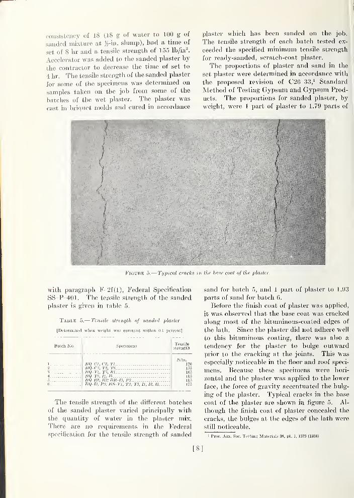
Figure 5.— Typical cracks in the base coat of the plaster.
with paragraph F-2f(l), Federal Specification
SS-P-401. The tensile strength of the sanded
plaster is given in table 5.
Table 5.— Tensile strength of sanded plaster
[Determined when weight was constant within O.l percent]
Batch No.
1.
23
4
5.
6
Specimens
BQ-Cl, C2, TlDQ-CS, T2, T3...BQ-Ti, T5, mBQ-T6, H,I5BQ-Rt, R3; BR-I3, PSBQ-I3, P3; BS-Tl, T2, T3, II, 72, IS
Tensilestrength
Ihlm.]20155165US115175
The tensile strength of the different batches
of the sanded plaster varied principally with
the quantity of water in the plaster mix.
There are no requirements in the Federal
specification for the tensile strength of sanded
sand for batch 5, and 1 part of plaster to 1.93
parts of sand for batch 6.
Before the finish coat of plaster was applied,
it was observed that the base coat was cracked
along most of the bituminous-coated edges of
the lath. Since the plaster did not adhere well
to this bituminous coating, there was also a
tendency for the plaster to bulge outward
prior to the cracking at the jomts. This was
especially noticeable in the floor and roof speci-
mens. Because these specimens were hori-
zontal and the plaster was applied to the lower
face, the force of gravity accentuated the bulg-
ing of the plaster. Typical cracks in the base
coat of the plaster are shown in figure 5. Al-
though the finish coat of plaster concealed the
cracks, the bulges at the edges of the lath were
still noticeable.
• Proc. Am. Soc. Testing Materials 38, pt. 1, 1323 (1938).
[8]
6. Sheathing Paper
Red-rosin paper, weight 40 lb/108 ft^ 36 in.
width of roll. Bird & Son, Inc.
7. Tacks
BUl-poster tacks, }^ in. long, diam of head
% in., size No. 6.
8. Size
Decorator's size, alum-treated animal glue
and mineral fillers. Recommended mixture
for plaster, 1 lb to 6 qt of water. M. EwingFox Co.'s "Fox Decorator's Size."
9. Paints
(a) Outside
E. I. du Pont de Nemours and Co.'s "Du-pont Outside White No. 40."
The outside paints were prepared as follows:
Primer—a mixture of 1 gal of outside white,
3 pt of raw linseed oil, and 1 pt of turpentine.
Undercoat—a mixture of 1 gal of outside
white and 1 pt of turpentine.
Finish—a mixture of 1 gal of outside white
and 1 pt of linseed oil.
The formula for the outside white paint is
given in table 6.
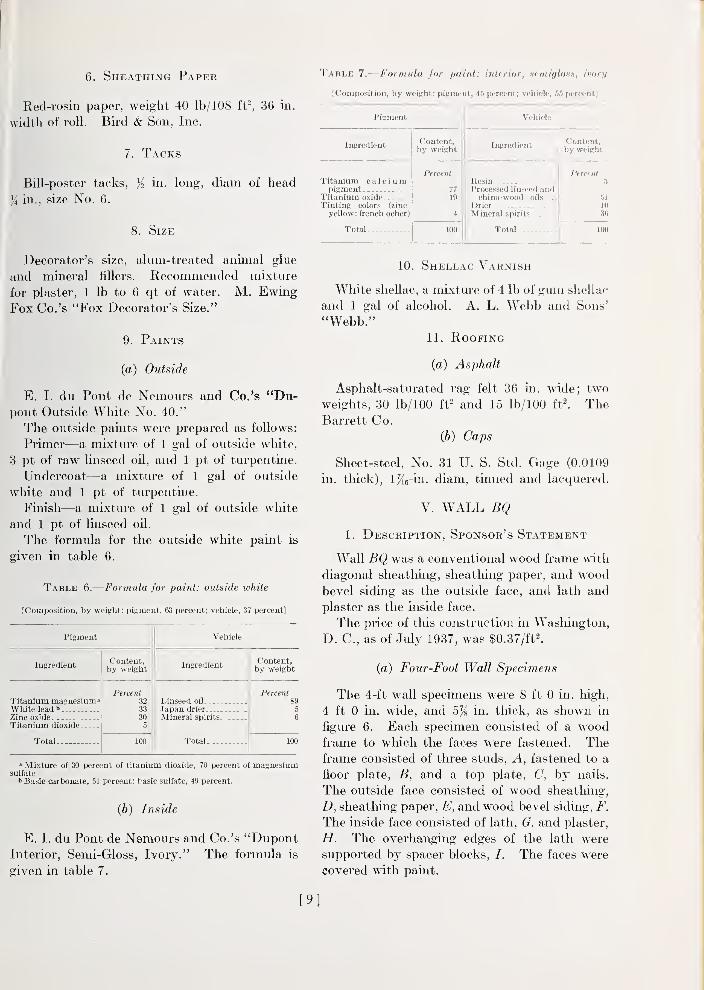
Table 6.
—
Formula for paini: outside white
[Composition, by weigiit: pigment, 63 percent; vehicle, 37 percent]
Pigment Vehicle
IngredientContent,by weight
IngredientContent,by weight
Titanium maenesium"White leadbZinc oxide_ _ .
Titanium dioxide .
Total
Percent32
333(1
5
Linseed oil .
Japan drier
Mineral spirits.
Total
Percent895
6
100 100
» Mixture of 30 percent of titanium dioxide, 70 percent of magnesiumsulfate
t Basic carbonate, 51 percent; basic sulfate, 49 percent.
(b) Inside
E. I. du Pont de Nemours and Co.'s "DupontInterior, Semi-Gloss, Ivory." The formula is
given in table 7.
Table 7.
—
Formula for paint: irderior, HemiglonH, ivory
[Composition, by weight: pigment, 45 perceni; vehicle, 55 percent]
Pigment Vehicle
IngredientContent,by weight
IngredientContent,by weight
Percentli
51
10
36
100
Titanium calciumpigment
Titanium oxideTinting colors (zinc
yellow; french ocher)
Total
Percent
77
19
4
100
ResinProcessed linseed andchina-wood oils
Drier...Mineral spirits
Total -.
10. Shellac Varnish
White shellac, a mixture of 4 lb of guin shellac
and 1 gal of alcohol. A. L. Webb and Sons'
"Webb."11. Roofing
(a) Asphalt
Asphalt-saturated rag felt 36 in. wide; two
weights, 30 lb/100 ft^ and 15 lb/100 ft^. TheBarrett Co.
(b) Caps
Sheet-steel, No. 31 U. S. Std. Gage (0.0109
m. thick), iKe-hi. diam, tinned and lacquered.
V. WALL BQ
1. Description, Sponsor's Statement
Wall BQ was a conventional wood frame wdth
diagonal sheathing, sheathing paper, and woodbevel siding as the outside face, and lath and
plaster as the inside face.
The price of tlds construction in Washington,
D. C, as of July 1937, was §0.37/ft2.
(a) Four-Foot Wall Specimens
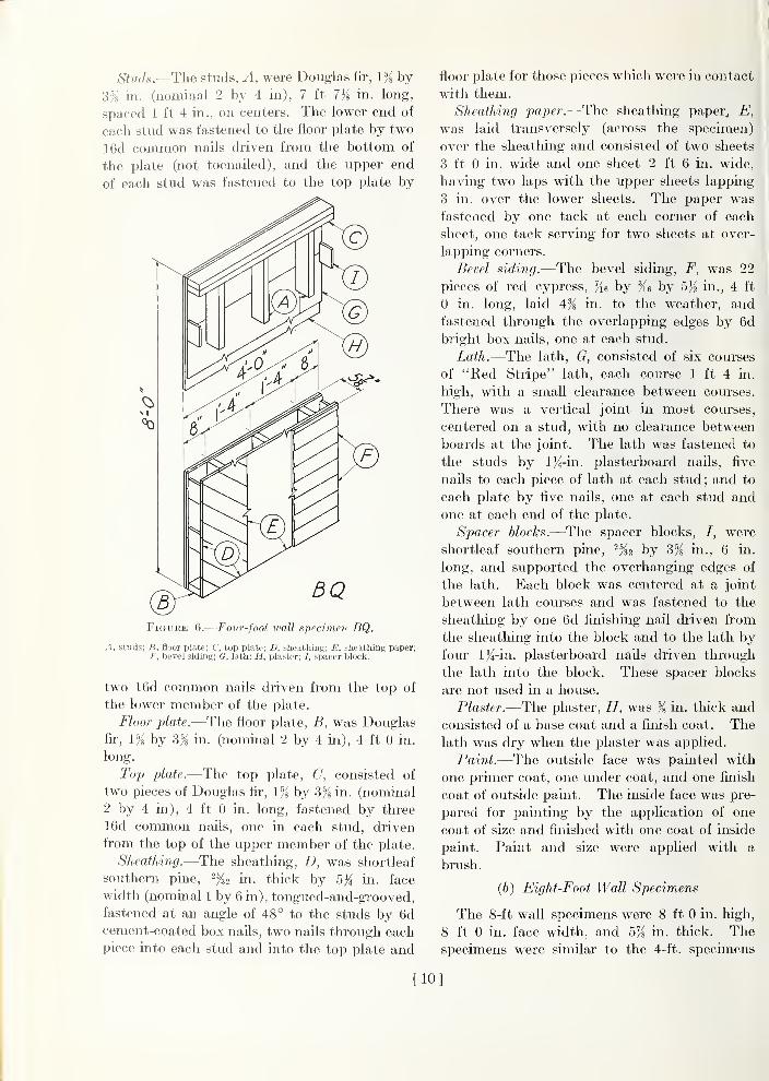
The 4-ft wall specimens were 8 ft 0 in. high,
4 ft 0 in. wide, and 5% in. thick, as shown in
figure 6. Each specimen consisted of a woodframe to which the faces were fastened. Theframe consisted of three studs, A, fastened to a
floor plate, B, and a top plate, C, by nails.
The outside face consisted of wood sheatliing,
D, sheathuig paper, E, and wood bevel siding, F.
The inside face consisted of lath, (?. and plaster,
H. The overhanging edges of the lath were
supported by spacer blocks, /. The faces were
covered with paint.
[9]
Studs.—The studs, A, were Douglas fii-, \% by
3% in. (nominal 2 by 4 in), 7 ft 7)i in. long,
spaced 1 ft 4 in., on centers. The lower end of
each stud was fastened to the floor plate by two
16d common nails driven from the bottom of
the plate (not toenailed), and the upper end
of each stud was fastened to the top plate by
Figure 6.
—
Four-foot wall specimen BQ.
A, studs; B, floor plate; C, top plate; V, sheathing; E, sheathing paper;F, bevel siding; 6, lath; H, plaster; /, spacer Ijlock.
two 16d common nails driven from the top of
the lower member of the plate.
Floor plate.—The floor plate, B, was Douglasfir, 1% by 3% in. (nomhial 2 by 4 hi), 4 ft 0 in.
long.
Top plate.—The top plate, C, consisted of
two pieces of Douglas fir, l'% by 3% in. (nominal
2 by 4 in), 4 ft 0 in. long, fastened by three
16d common nails, one in each stud, driven
from the top of the upper member of the plate.
Sheathing.—The sheatliing, D, was shortleaf
southern pine, -fzi in. thick by 5}^ in. face
width (nominal 1 by 6 in), tongued-and-grooved,
fastened at an angle of 48° to the studs by 6dcement-coated box naUs, two nails through eachpiece into each stud and into the top plate and
floor plate for those pieces which were ui contact
with them.
Sheathing paper.—The sheathing paper, E,
was laid transversely (across the specimen)
over the sheatliing and consisted of two sheets
3 ft 0 in. wide and one sheet 2 ft 6 in. wide,
having two laps with the upper sheets lapping
3 in. over the lower sheets. The paper was
fastened by one tack at each corner of each
sheet, one tack serving for two sheets at over-
lapping corners.
Bevel siding.—The bevel siding, F, was 22
pieces of red cypress, by hj 5K in., 4 ft
0 in. long, laid 4% in. to the weather, and
fastened through the overlapping edges by 6d
bright box nails, one at each stud.
Lath.—The lath, G, consisted of six courses
of "Ked Stripe" lath, each course 1 ft 4 in.
high, with a small clearance between courses.
There was a vertical joint in most courses,
centered on a stud, with no clearance between
boards at the joint. The lath was fastened to
the studs by l^-in. plasterboard nails, five
nails to each piece of lath at each stud; and to
each plate by five nails, one at each stud and
one at each end of the plate.
Spacer blocks.—The spacer blocks, /, were
shortleaf southern pine, by Sji in., 6 in.
long, and supported the overhanging edges of
the lath. Each block was centered at a joint
between lath courses and was fastened to the
sheathing by one 6d finishing nail driven from
the sheatliing into the block and to the lath byfour l)4-in. plasterboard nails driven through
the lath into the block. These spacer blocks
are not used in a house.
Plaster.—The plaster, H, was % in. thick and
consisted of a base coat and a finish coat. Thelath was dry when the plaster was applied.
Paint.—The outside face was painted with
one primer coat, one under coat, and one finish
coat of outside paint. The inside face was pre-
pared for painting by the application of one
coat of size and finished with one coat of inside
paint. Paint and size were applied with a
brush.
(6) Eight-Foot Wall Specimens
The 8-f t wall specimens were 8 ft 0 in. high,
8 ft 0 in. face width, and 5% in. thick. Thespecimens were similar to the 4-ft. specimens
[10]
except that there were seven studs, spaced 1 ft
4 in. on centers, and no spacer blocks. Therewas a stud at each edge extending one-half its
thickness beyond the faces, width over-all 8
ft 1% in.
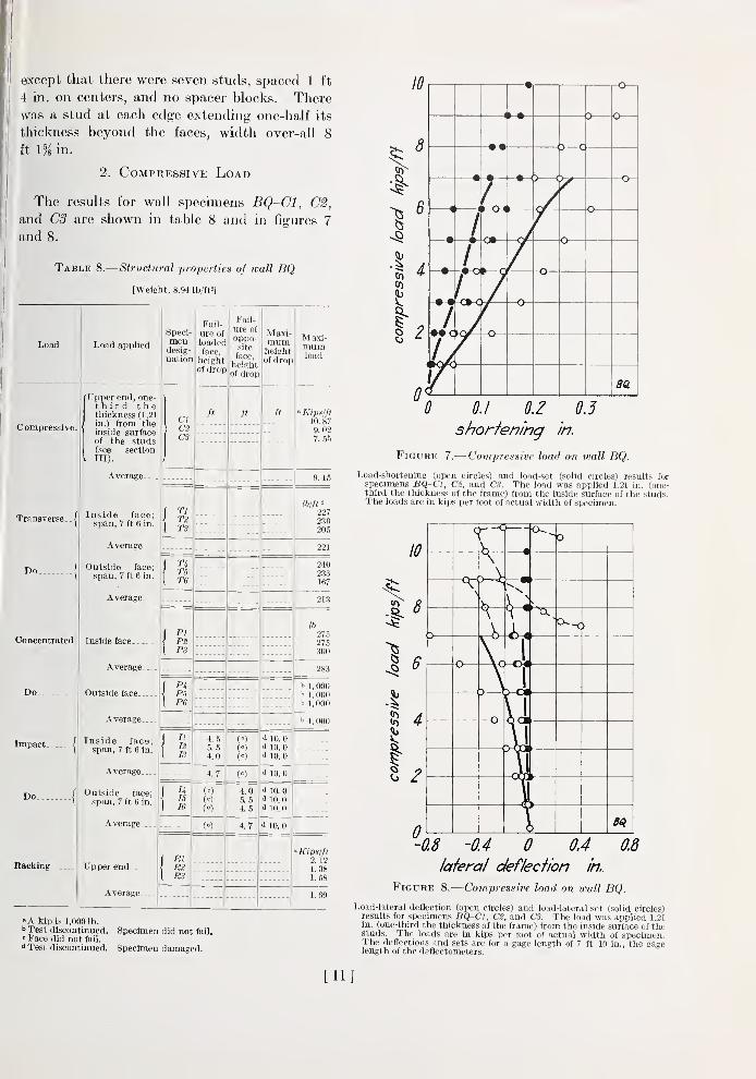
2. Compressive Load
The results for wall specimens BQ-Cl, C2,
and C3 are shown in table 8 and in figures 7
and 8.
Table 8.
—
Structural properties of wall BQ
[Weight, 8.94 lb/ft«]
Load
Compressive.
Load applied
Upper end, one-third thethickness (1.21
in.) from theinside surfaceof the studs(see sectionni).
Average
Transverse.
Do.
Concentrated
Impact.
Do.
Racking.
Inside face;span, 7 ft 6 in.
Average .
.
Outside face;
span, 7 ft 6 in.
Average.
Inside face.
Average-
Outside face-.
Average..
Speci-
mendesig-
nation
TlTB
nTBT6
PI
Inside face;span, 7 ft 6 in.
Average...
Outside face;span, 7 ft 6 in.
Average..
-
Upper end
Average.
Fail-
ure of
loadedface,
heightof drop
Fail-
ure of
oppo-.site
face,
heightof drop
RlR2RS
4.55.54.0
4.7
(0)
Maxi-mumheightof drop
Maxi-mumload
» Kips/fl10. 879. 027. 55
(")
(°)
(«)
(<=)
4.05.54.5
4.7
d 10.0•i 10.0<J 10.0
i 10. 0
<> 10.0d 10.0d 10.0
i 10.0
lb/ft'
227230205
221
240233167
213
275275300
i» 1, 000!• 1,000b 1, 000
i»1, 000
•'Kips/fl2. 121.381.58
1.
»A kip is 1,0001b.^ Test discontinued. Specimen did not fail."Face did not fail."i Test discontinued. Specimen damaged.
10
•I ^CO
I2
(
• r-O1
'
D o
—
•
-•-< >—
<
>—
c
rh-CH
—o-
4
• /
1 O
•T
\ C
o
L-o—
11
u
—o-
Ba
0 0.1 O.Z OJshorfening in.
Figure 7.
—
Compressive load on wall BQ.
Load-shortening (open circles) and load-set (solid circles) results forsp(H-iTni'n,s liQ-Cl, C2, and C3. The load was applied 1.21 in. (one-third the thickness of the frame) from the inside surface of the studs.The loads are in kips per foot of actual width of specimen.
I
\—
c
o
V «
rD i
—
>
—Vco
—
1 D J
—
0
3^
'-0.8 -OA 0 04 0.8
lateral deflecfion in..
Figure 8.
—
Com-pressive load on wall BQ.
Load-lateral deflection (open circles) and load-lateral set (solid circles)results for .speciraons BQ-Cl, C2, and CS. The load was applied 1.21in. (one-t liinl I hr thickness of the frame) from the inside surface cf thestuds. Thr luiids irr in kips per foot of actual width of specimen.The deflections and sets are for a gage length of 7 ft 10 in., the gagelength of the deflectometers.
[11]
Although the load was eccentric toward the
inside face, each of the specimens deflected
toward the inside face under loads up to the
maximum load, probably because the stiffness
of the plaster counteracted the effect of the
eccentric load. After the maximum had been
reached, specimens CI and C2 deflected in the
240
ZOO
160
120
80
40
• a
•
/
-T'f
I-1
1
t—r J• ex
la
I 2
deflecfion in.
3
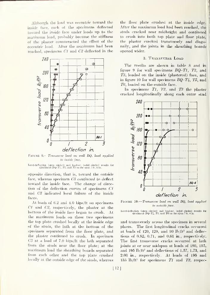
Figure 9.— Transverse load on wall BQ, load applied
to inside face.
Load-deflection (open circles) and load-set (solid circles) results for
specimens BQ-Tl, T2, and T3 on the span 7 ft. 6 in.
opposite direction, that is, toward the outside
face, whereas specimen C3 continued to deflect
toward the inside face. The change of direc-
tion of the deflection curves of specimens CI
and C2 indicated local failure of the inside
faces.
At loads of 6.2 and 4.0 kips/ft on specimens
Cl and C2, respectively, the plaster at the
bottom of the inside face began to crush. Atthe maximum loads on these two speciBiens
the top plate crushed iocaUy at the inside edge
of the studs, the lath at the bottom of the
specimen separated from the floor plate, andthe plaster continued to crush. In specimenC3 at a load of 7.0 kips/ft the lath separated
from the studs near the floor plate; at the
maximum load the sheathing boards separated
from each other and the top plate crushedlocaUy at the outside edge of the studs, whereas
the floor plate crushed at the inside edge.
After the maximum load had been reached, the
studs cracked near midheight and continued
to crush into both top plate and floor plate,
the plaster cracked transversely and diago-
naUy, and the joints in the sheathing boards
opened wider.
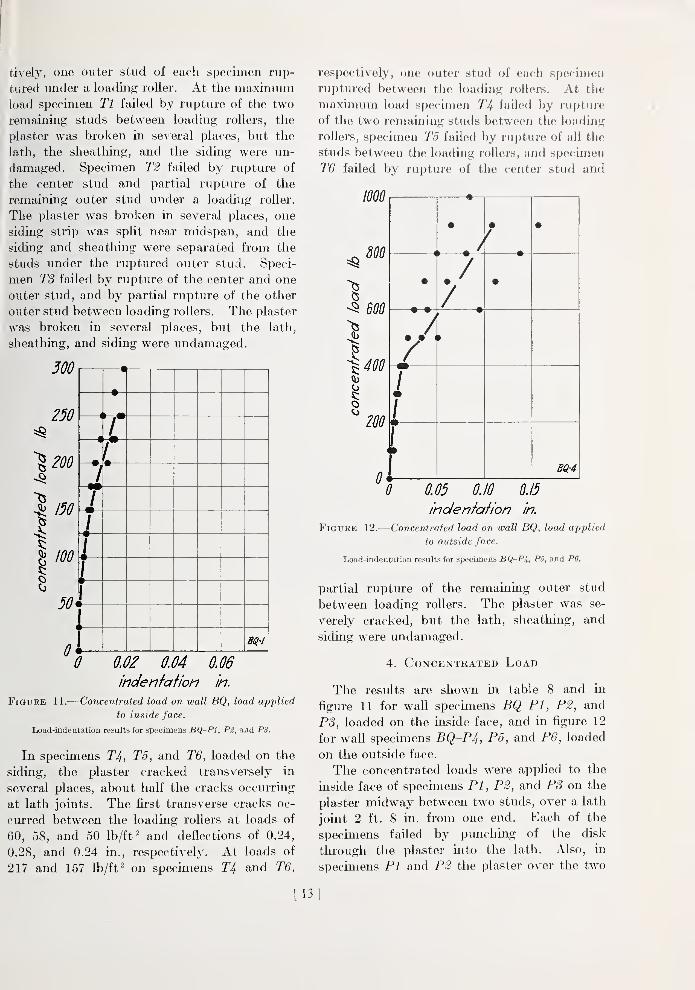
3. Transverse Load
The results are shown in table 8 and in
figure 9 for wall specimens BQ~T1, T2, andT3, loaded on the inside (plastered) face, andin figure 10 for wall specimens BQ-T4, T5, and
T6, loaded on the outside face.
In specimens Tl, T2, and T3 the plaster
cracked longitudinally along each outer stud
?40
200
I
160
120
80
( ) c y
-••
—
c » c ^
—o— -o
•
—
1•1•
—
\f
BQ-4
I 2
deflecfion in.
Figure 10.— Transverse load on wall BQ, load applied
to outside face.
Load-deflection (open circles) and load-set (solid circles) results for
specimens BQ-Ti, T5, and T6 on the span 7 ft. 6 in.
and trans\' ersely across the specimen in several
places. The first longitudinal cracks occurred
at loads of 120, 120, and 90 Ib/ft^ and deflec-
tions of 0.82, 0.71, and 0.61 in., respectively.
The first transverse cracks occurred at lath
joints at or near midspan at loads of 180, 195,
and 195 Ib/ft^ and deflections of 1.57, 1.73, and
2.03 in., respectively. At loads of 195 and
135 Ib/ft^ for specimens Tl and T2, respec-
[12]
tively, one outer stud of each specimen rup-
tured under a loading roller. At the maximumload specimen Tl failed by rupture of the two
remaining studs between loading rollers, the
plaster was broken in several places, but the
hxth, the sheatliing, and the siding were un-
damaged. Specimen T2 failed by rupture of
the center stud and partial rupture of the
remaining outer stud under a loading roller.
The plaster was broken in several places, one
siding strip was split near midspan, and the
siding and sheatliing were separated from the
studs under the ruptured outer stud. Speci-
men T3 failed by rupture of the center and one
outer stud, and by partial rupture of the other
outer stud between loading rollers. The plaster
was broken in several places, but the lath,
sheathing, and siding were undamaged.
250
'\200
150
I
1 100
50*
m
•
—
(
r—
«
r1
1•
—
L1»
—
1>
—
>—
n
.
1
0
indenfafion in.
Figure 11.
—
Concentrated load on wall BQ, load applied
to inside face.
Load-indeQtation results for specimens BQ-Pl, P2, aad PS.
In specimens T4, T5, and T6, loaded on the
siding, the plaster cracked transversely in
several places, about half the cracks occurring
at lath joints. The first transverse cracks oc-
curred between the loading rollers at loads of
60, 58, and 50 lb/ft" and deflections of 0.24,
0.28, and 0.24 in., respectively. At loads of
217 and 157 Ib/ft^ on specimens T4 and T6,
respectively, one outer stud of each specimen
ruptured between the loading rollers. At the
maximum load specimen T4 failed by rupture
of the two remaining studs between the loading
rollers, specimen T5 failed by rupture of ail the
studs between the loading rollers, and specimen
T6 failed by rupture of the center stud and
mo
I
o
o
800
600
400
200
0
1
•
—
• • •
<
• ./
•
•
• •
A1m
1m
1
< 1
BQ-4
0 0.05 0.10 0.15
inden/a/ion in.
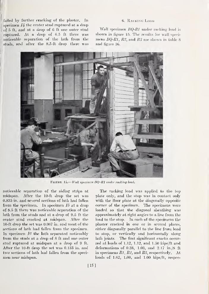
Figure 12.
—
Concentrated load on wall BQ, load applied
to outside face.
Load-indentation results for specimens BQ-Pi, PS, and PS.
partial rupture of the remaining outer stud
between loading rollers. The plaster was se-
verely cracked, but the lath, sheathing, and
siding were undamaged.
4. Concentrated Load
The results are shown in table 8 and in
figure 11 for wall specimens BQ-Pl, P2, and
PS, loaded on the inside face, and in figure 12
for wall specmiens BQrP/i., P5, and P6, loaded
on the outside face.
The concentrated loads were applied to the
inside face of specimens PI,P2, and PS on the
plaster midway between two studs, over a lath
joint 2 ft. 8 in. from one end. Each of the
specimens failed by punching of the disk
through the plaster into the lath. Also, in
specimens PI and P2 the plaster over the two
[13]
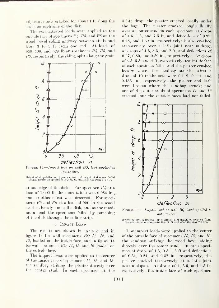
adjacent studs cracked for about 1 ft along the
studs on each side of the disk.
The concentrated loads were applied to the
outside face of specimens PJf., P5, and P6 on the
wood bevel siding midway between studs and
from 3 to 4 ft from one end. At loads of
900, 400, and 529 lb on specimens PJ^, P5, and
P6, respectively, the siding split along the grain
10
8
4
2
0
r-« 1
1
1
1
O £
>j—o
J O
1
1
LJ\J \J
1•1
1
Tc/o
•
» CO
0 0.5 1.0 1.5
deflecfion in.
Figure 13.
—
Im-pact load on wall BQ, load applied to
inside face.
Height of drop-deflection (open circles) and height of drop-set (solidcircles) results for specimens BQ-Il, 12, and IS on the span 7 ft 6 in.
at one edge of the disk. For specimen P4 at a
load of 1,000 lb the indentation was 0.084 in.,
and no other effect was observed. For speci-
mens P6 and P6 at a load of 900 lb the woodcrushed locally imder the disk, and at the maxi-
mum load the specimens failed by punchingof the disk through the siding strip.
5. Impact Load
The results are shown in table 8 and in
figure 13 for waU specimens BQ-Il, 12, and13, loaded on the inside face, and in figure 14
for waU specimens BQ-I4, 15, and 16, loaded onthe outside face.
The impact loads were applied to the center
of the inside face of specimens U, 12, and 13,
the sandbag striking the plaster directly overthe center stud. In each specimen at the
3.5-ft drop, the plaster cracked locally under
the bag. The plaster cracked longitudinally
over an outer stud in each specimen at drops
of 4.5, 1.5, and 7.5 ft, and deflections of 0.97,
0.48, and 1.30 in., respectively; it also cracked
transversely over a lath joint near midspanat drops of 4.5, 3.5, and 2 ft, and deflections of
0.97, 0.80, and 0.59 in., respectively. At drops
of 4.5, 5.5, and 4 ft, respectively, the inside face
of each specimen failed and the plaster crushed
locally where the sandbag struck. After a
drop of 10 ft the sets were 0.118, 0.111, and
0.136 in., respectively; the plaster and lath
were broken where the sandbag struck; andone of the outer studs of specimens II and 12
cracked, but the outside faces had not failed.
10
8
I'
2
7—^-^ r-O-1
0c
-ocj
»
•
-0—
M
—
-00
c )<D-4
1
Bei-4
I 2defiedion in
Figure 14. -Impact load on wall BQ, load applied to
outside face.
Height of drop-deflection (open circles) and height of drop-set (solid
circles) results for specimens BQ-IJ,, IS, and 16 on the span 7 ft 6 in.
The impact loads were applied to the center
of the outside face of specimens 14, 15, and 16,
the sandbag striking the wood bevel siding
directly over the center stud. In each speci-
men at drops of 1.5, 0.5, 1.5 ft and deflections
of 0.51, 0.24, and 0.52 in., respectively, the
plaster cracked transversely at a lath joint
near midspan. At drops of 4, 5.5, and 4.5 ft,
respectively, the inside face of each specimen
[14]
failed by further cracking of tlie plaster. In
specimen 14 the center stud ruptured at a drop
of 5 ft, and at a drop of 6 ft one outer stud
ruptured. At a drop of 6.5 ft there was
noticeable separation of the lath from the
studs, and after the 8.5-ft drop there was
6. Racking J^oad
Wall specimen BQ-Rl iinder racking load is
shown in figure 15. The results for wall sj)eci-
mens BQ-Rl, R2, and R3 are shown in table 8
and figure 10.
• V.J
Figure 15.— Wall specimen BQ-Rl under racking load.
noticeable separation of the siding strips at
midspan. After the 10-ft drop the set was
0.835 in. and several sections of lath had fallen
from the specimen. In specimen 15 at a drop
of 8.5 ft tliere was noticeable separation of the
lath from the studs and at a drop of 9.5 ft the
center stud cracked at midspan. After the
10-ft drop the set was 0.067 in. and most of the
sections of lath had fallen from the specimen.
In specimen 16 the lath separated noticeably
from the studs at a drop of 8 ft and one outer
stud ruptured at midspan at a drop of 9 ft.
After the 10-ft drop the set was 0.133 in. and
two sections of lath had fallen from the speci-
men near midspan.
The racking load was applied to the top
plate only, and the stop was in contact only
with the floor plate at the diagonally opposite
corner of the specimen. The specimens were
loaded so that the diagonal sheathing wasapproximately at right angles to a line from the
load to the stop. In each of the specmiens the
plaster cracked in one or in several places,
either diagonally parallel to the line from load
to stop, or vertically and horizontally along
lath joints. The first significant cracks occur-
red at loads of 1.12, 1.12, and 1.50 Idps/ft anddeformations of 0.38, 1.03, and 2.17 in./8 ft
in specimens Rl, R2, and R3, respectively. Atloads of 1.62, 1.00, and 1.00 kips/ft, respec-
[15]
tively, there was noticeable displacement of
the top plate with respect to the sheathing and
the lath, the naUs pulling through the edges of
the sheathing and the lath. At the maximumload each of the specimens failed by shearing
of the top plate and studs from the sheathing
and lath and by displacement of the top plate
horizontally with respect to the studs, the nails
2.0
/.6
L2
fO.8
0
wr*—
1
O
• O
o
1 C < » o
• o
0 12^deformation in./Sff
Figure 16.
—
Rackinq load on wall BQ.
Load-deformation (open circles) and load-set (solid circles) results for
specimens BQ-Rl, R2, and RS. The loads are in kips per foot of
the face width of specimen (8 ft 0 in).
pulling from the studs and splitting some of
the studs at the upper end.
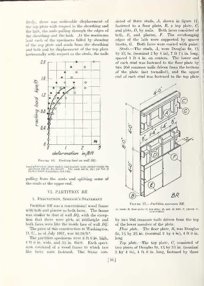
VI. PARTITION BR
1. Description, Sponsor's Statement
Partition BR was a conventional wood frame
with lath and plaster as both faces. The frame
was similar to that of wall BQ, with the excep-
tion that there were girts at midheiglit andboth faces were like the inside face of wall BQ.The price of this construction in Washington,
D. C, as of July 1937, was $0.29/ft^
The partition specimens were 8 ft 0 in. high,
4 ft 0 in. wide, and 5}^ in. thick. Each speci-
men consisted of a wood frame to which twolil^e faces were fastened. The frame con-
sisted of three studs. A, shown in figure 17,
fastened to a floor plate, B, a top plate, C,
and girts, D, by nails. Both faces consisted of
lath, E, and plaster, F. The overhanging
edges of the lath were supported by spacer
blocks, G. Both faces were coated with paint.
Studs.—The studs. A, were Douglas fir, 1^
by 3% in. (nominal 2 by 4 in), 7 ft 7K in- long,
spaced 1 ft 4 in. on centers. The lower end
of each stud was fastened to the floor plate by
two 20d common nails driven from the bottom
of the plate (not toenailed), and the upper
end of each stud was fastened to the top plate
Figure 17.
—
Partition specimen BR.
A, studs; B, floor plate; C, top plate; D, girt; E, lath; F, plaster; G,spacer block.
by two 20d common nads driven from the top
of the lower member of the plate.
Floor plate.—The floor plate, B, was Douglas
fir, 1% by 3% in. (nominal 2 by 4 in), 4 ft 0 in.
long.
Top plate.—The top plate, C, consisted of
two pieces of Douglas fir, 1% by Zft, in. (nominal
2 by 4 in), 4 ft 0 in. long, fastened by three
[16]
20d common nails, one in each stud, driven
from the top of the top plate.
Girts.—The girts, D, were Douglas fir,
1% by 3% in. (nominal 2 by 4 in). The two
inner pieces, 1 ft 2% in. long, were fastened at
midheight to the outer studs by either two
16d or two 20d common nails driven through
the stud into the girt, and were toenailed to the
center stud by two 6d bright box nails. Thetwo outer pieces, 6^8 in. long, were placed
and supported the overlianging edges of the
lath. Eiich block was centered at a joint be-
tween lath courses, and was fastened to the
lath by four Iji-m. plasterboard nails driven
through the lath into the block. These spacer
blocks are not used in a house.
Plaster.—The plaster, F, was % in. thick andconsisted of a base coat and a finish coat.
The lath was dry when the plaster was applied.
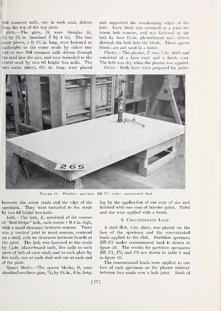
Paint.—Both faces were prepared for paint-
FiGURE 18.
—
Partition specimen BR-P2 under concentrated load.
between the outer studs and the edge of the
specimen. They were toenailed to the studs
by two 6d bright box nails.
Lath.—The lath, E, consisted of six courses
of "Red Stripe" lath, each course 1 ft 4 in. high,
with a small clearance between courses. There
was a vertical joint in most courses, centered
on a stud, with no clearance between boards at
the joint. The lath was fastened to the studs
by 1/^-in. plasterboard naUs, five nails to each
piece of lath at each stud ; and to each plate byfive naUs, one at each stud and one at each end
of the plate.
Spacer blocks.—The spacer blocks, G, were
shortleaf southern pine, by d% in., 6 in. long,
mg by the application of one coat of size and
finished with one coat of interior paint. Paint
and size were applied with a brush.
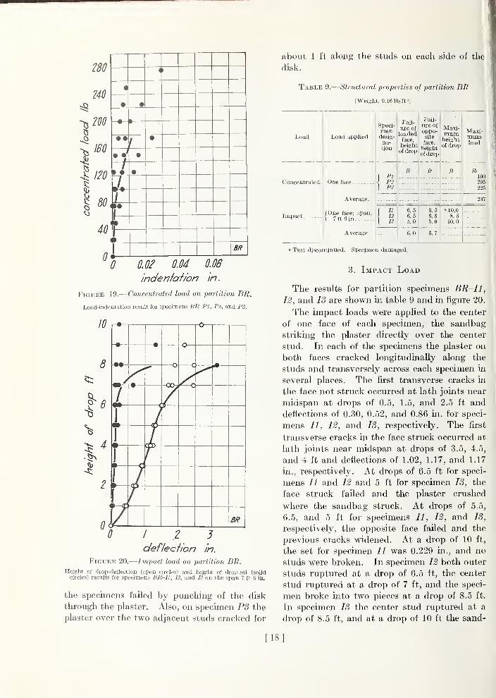
2. Concentrated Load
A steel disk, 1-in. diam, was placed on the
face of the specimen and the concentrated
loads applied to the disk. Partition specimen
BR-P2 under concentrated load is showm in
figure 18. The results for partition specimens
BR~P1, P2, and PS are shown m table 9 andin figure 19.
The concentrated loads were applied to one
face of each specimen on the plaster midwaybetween two studs over a lath joint. Each of
[17]
280
240
200
ISO
120
80
40
«
• •
• • •
.J1
•
1> • •
/' WW
•1•
—
BR
^0 0.02 OM 0.06
indenfah'on in.
Figure 19.
—
Concentrated load on partition BR.
Load-indentation result fur specimens BR-Pl, P2, and PS.
10
8
I'
0
[-•— pO
—
• —•- -o
—
—
a
—
c
/
•
—
•
—
1•
—
1»
—
y BR
0 12 3deflecfion in.
Figure 20.
—
Impact load on partition BR.Height of drop-deflection (open circles) and height of drop-set (solid
circles) results for specimens BR-Il, 12, and IS on the span 7 ft 6 in.
the specimens failed by punching of the disk
through the plaster. Also, on specimen PS the
plaster over the two adjacent studs cracked for
about 1 ft along the studs on each side of the
disk.
Table Si.— -Structural properties of partition BR
(Weight, 9.16 lb/ft 2]
Load Load applied
Speci-
desig-na-tion
Fail-
ure of
loadedface,
heightof drop
Fail-ure of
site
face,
heightof drop
Maxi-mumheightof drop
M!axi-miimload
Concentrated.
Impact
One face.. .
f PI\ P2\ PS
ft ft ft lb
190295225
Average 237
/One face; span,\ 7 ft 6 in
\ 12
{ IS
6. 5
6.55.0
5.56.55.0
a 10.0
8. 5
10.0
Average 6.0 5.7
' Test discontinued. Specimen damaged.
3. Impact Load
The results for partition specimens BR-Il,
12, and IS are shown in table 9 and in figure 20.
The impact loads were applied to the center
of one face of each specimen, the sandbag
striking the plaster directly over the center
stud. In each of the specimens the plaster on
both faces cracked longitudinally along the
studs and transversely across each specimen in
several places. The fii-st transverse cracks in
the face not struck occurred at lath joints near
midspan at drops of 0.5, 1.5, and 2.5 ft and
deflections of 0.30, 0.52, and 0.86 in. for speci-
mens II, 12, and IS, respectively. The first
transverse cracks in the face struck occurred at
lath joints near midspan at drops of 3.5, 4.5,
and 4 ft and deflections of 1.02, 1.17, and 1.17
in., respectively. At drops of 6.5 ft for speci-
mens II and 12 and 5 ft for specimen 13, the
face struck failed and the plaster crushed
where the sandbag struck. At drops of 5.5,
6.5, and 5 ft for specimens II, 12, and IS,
respectively, the opposite face failed and the
previous cracks widened. At a drop of 10 ft,
the set for specimen II was 0.229 in., and no
studs were broken. In specimen 12 both outer
studs ruptured at a drop of 6.5 ft, the center
stud ruptured at a drop of 7 ft, and the speci-
men broke into two pieces at a drop of 8.5 ft.
In specimen IS the center stud ruptured at a
drop of 8.5 ft, and at a drop of 10 ft the sand-
[18]
bag broke completely through the specimen;
the two outer studs were undamaged.
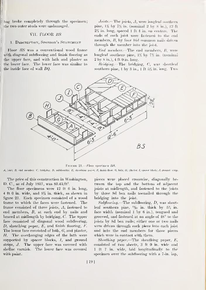
VII. FLOOR BS
1. Description, Sponsor's Statement
Floor BS was a conventional wood frame
with diagonal subflooring and finish flooring as
the upper face, and with lath and plaster as
the lower face. The lower face was similar to
the inside face of wall BQ.
Joists.—The joists. A, were longleaf soiitliom
pine, lYs by 7% in. (nominal 2 by 8 in.), 12 ft
2% in. long, spaced 1 ft 4 in. on centers. Theends of each joist were fastened to the end
members, B, by four IGd common nails driven
th]-ough the member into the joist.
End members.—The end members, B, were
longleaf southern pine, 1% by 7% in. (nominal
2 by 8 in.), 4 ft 0 in. long.
Bridging.—The bridging, C, was shoi-tleuf
southern pine, 1 by 3 in., 1 ft 5}^ in. long. Two
Figure 21.
—
Floor specimen BS.
A, joist; B, end member; C, bridging; D, subflooring; E, sheathing paper; F, finish floor; G, lath; H, plaster; 7, spacer block; J, ground strip.
The price of this construction in Washington,
D. C, as of July 1937, was $0.43/ftl
The floor specimens were 12 ft 6 in. long,
4 ft 0 in. wide, and 9% in. thick, as shown in
flgure 21. Each specimen consisted of a woodframe to which the faces were fastened. Theframe consisted of three joists, A, fastened to
end members, B, at each end by nails and
braced at midlength by bridging, C. The upper
face consisted of diagonal wood subflooring,
D, sheathing paper, E, and finish flooring, F.
The lower face consisted of lath, G, and plaster,
H. The overhanging edges of the lath were
supported by spacer blocks, /, and ground
strips, J. The upper face was covered with
shellac A^arnish. The lower face was covered
with paint.
pieces were placed crosswise, diagonally be-
tween the top and the bottom of adjacent
joists at midlength, and fastened to the joists
by three 8d box nails toenailed through the
bridging into the joist.
Subflooring.—The subflooring, D, was short-
leaf southern pine, in. thick by 5^ in.
face width (nominal 1 by 6 in.), tongued and
grooved, and fastened at an angle of 48° to the
joists by 8d box nails; either one or two nails
were driven through each piece into each joist
and into the end members for those pieces
which were in contact with them.
Sheathing paper.—The sheathing paper, E,
consisted of two sheets, 3 ft 0 in. wide and
1 ft 7 in. wide, laid longitudinally to the
specimen over the subflooring with a 7-in. lap,
[19]
and fastened to the subflooring at each end of
the specimen by nme tacks.
Finish flooring.—The fuiish flooring, F, was
white oak, in. thick by 2% in. face width,
tongued-and-grooved, bhnd-fastened to each
joist by one 8d cut flooring nail driven into
each piece through the subflooring and into tiie
joist. The flooring strip at one end of the
600
m
I 300
^ 200
\^ 100
0
1
—
[—o-
• —o-
D•—
'
•
—
T—o-
o
/
—
o
ro
1
0
r»
—
i
u35
0 I 2 5
def/ec/ior? in.
Figure 22.— Transverse load on floor BS.
Load-deQection (open circles) and load-set (solid circles) results tor
specimens BS-Tl, T2. and IS on the span 12 ft 0 in.
specimen was also fastened by tluee 8d finish-
ing nails driven from the face of the strip into
the end member. At the other end of the
specimen a half strip was used to cover the ex-
posed tongue of the preceding strip, and was
fastened to the subflooring by three 6d cement-
coated box nails toenailed from the exposed
edge of the strip into the subflooring.
Lath.—The lath, G, consisted of "Red Stripe"
lath, nine full courses and one course cut to 6
in. The lath was applied with a small clear-
ance between courses and with a longitudinal
joint in most courses, centered on a joist, with
no clearance between lath boards at the joint.
The lath was fastened to the joists by l^-in.
plasterboard nails, five nails to each piece of
lath at each joist; and to each end member by
five nails, one at each joist and one at each endof the member.
Spacer blocks.—The spacer blocks, /, wereshortleaf southern pine, ^^^2 by 6^%2 in., 6 in.
long, and supported the overhanging edges of
the lath. The blocks were centered at the
joints between lath courses, and rested onground strips. The blocks were fastened to the
ground strips and subflooring by 6d cement-coated box nails, two nails toenailed througheach block mto the subflooring and two nails
driven through the ground strip into the block.
Ground strips.—The ground strips, J, wereshortleaf southern pine, %i by 1% in., 12 ft
2% in. loiig. The lath was fastened to the
ground strips by l}^-in. plasterboard nafls, five
1000
o
800
600
400
200
0
"1
11
.
1
1
1
1•—
'
1•
—
1<»
—
IBS
0 0,0f OM 0.06
indenfafion in.
Figure 23.
—
Concentrated load on floor BS.
Load-indentation results for specimens BS-Pl, P2, and PS.
nails for each course driven tlu'ough the lath
into the strip. The gi-ound strips were cut at
each lath course just before the specimen wastested, so that they did not aft'ect the strength
of the specimen. These ground strips andspacer blocks are not used in a house.
Plaster.—The plaster, was % in. thick and
consisted of a base coat and a finish coat. Thelath was dry when the plaster was applied.
[20]
i
Paint and varnish.—The upper face was
finished with one coat of shellac varnish. The
lower face was prepared for painting by the
application of one coat of size and finished with
one coat of inside paint. Varnish, size, and
paint were applied with a brush.
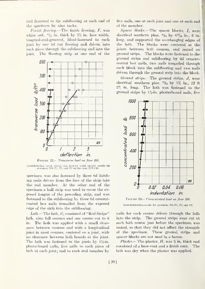
2. Transverse Load
j The results for floor specimens BS-Tl, T2,
jand T3 are shown in table 10 and in figure 22.
Table 10.
—
Structural properties of floor BS
[Weight, 13.0 Ib/ft^]
Load Load applied
Speci-mendesig-nation
Fail-
ure ofloadedface,
heightof drop
Fail-
ure of
oi)po-site
face,
heightof drop
Maxi-mumheightof drop
Maxi-mumload
Transverse
Concentrated.
Impact
(Upper face;
\span, 12 ft 0
[ in.
Average
I Tl\ T2[ TS
ft ft ft lb/ft'
640412448
500
Upper face.- ... i P2[ PS
lb
" 1,000« 1, 000" 1,000
Average » 1, 000
(Upper face;
\span, 12 ft 0
I in.
Average
\ a{ IS
mm(")
10.06.08.5
'lO. 0'10.0» 10.0
(") 8.2 a 10.0
» Test discontinued. Specimen did not fail,
k Face did not fail.
On specimens Tl,
T2, and TS the plaster
cracked transversely at most of the lath joints.
The first cracks occurred at loads of 35, 50, and
50 Ib/ft^ and deflections of 0.07, 0.14, and 0.17
in. in specimens Tl, T2, and T3, respectively.
At a load of 575 Ib/ft^ one outer joist of speci-
men Tl cracked between loading rollers, and at
the maximum load the specimen failed by rup-
ture of all the joists between the loading rollers.
In specimen T2 at a load of 350 Ib/ft^ one outer
joist cracked between loading rollers and at the
maximum load the specimen failed by rupturing
of the other outer joist and crushing at the top
of the center joist under a loading roller. Atthe maximum load specimen T3 failed by rup-
ture of an outer joist and the center joist be-
tween loading rollers. Neither the lath nor the
flooring separated appreciably from the joists
and no large pieces of plaster fell from the lath.
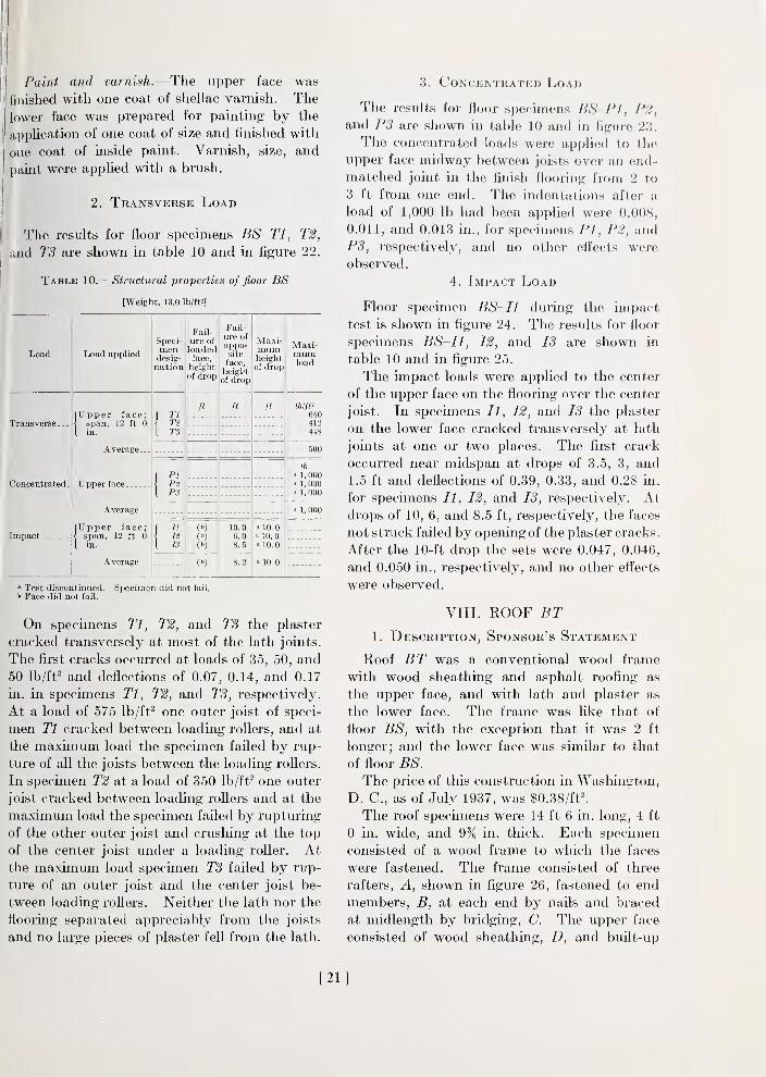
3. Concentrated Load
The results for floor si)ecimens BS PI,P2,
and PS are shown in table 10 and in figure 23.
The concentrated loads were applied to the
upper face midway between joists over an end-
matched joint in the finish flooring from 2 to
3 ft from one end. The indentations after a
load of 1,000 lb had been appUed were O.OOS,
0.011, and 0.013 in., for specimens PI, P2, and
PS, respectively, and no other effects were
observed
.
4. Impact Load
Floor specimen BS-Il during tlie impact
test is shown in figure 24. The results for floor
specimens BS~I1, 12, and IS are shown in
table 10 and in figure 25.
The impact loads were applied to the center
of the upper face on the flooring over the center
joist. In specimens II, 12, and IS the plaster
on the lower face cracked transversely at lath
joints at one or two places. The first crack
occurred near midspan at drops of 3.5, 3, and
1.5 ft and deflections of 0.39, 0.33, and 0.28 in.
for specimens II, 12, and IS, respectively. Atdrops of 10, 6, and 8.5 ft, respectively, the faces
not struck fafled by opening of the plaster cracks.
After the 10-ft drop the sets were 0.047, 0.046,
and 0.050 in., respectively, and no other effects
were observed.
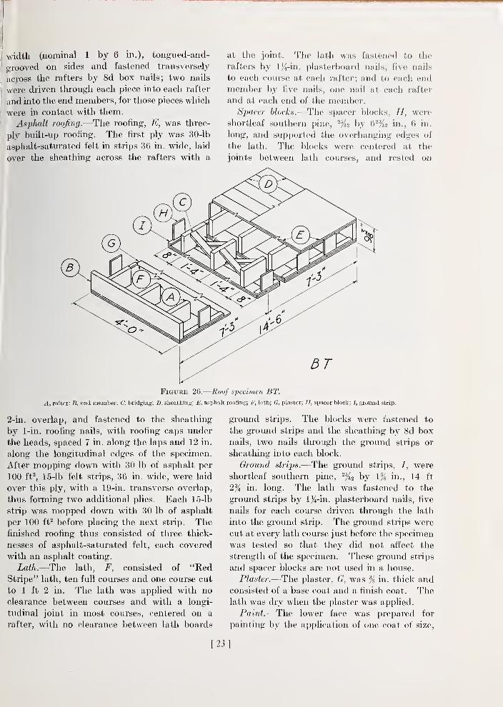
VIII. ROOF BT1. Description, Sponsor's Statement
Roof BT was a conventional wood frame
with wood sheathing and asphalt roofing as
the upper face, and with lath and plaster as
the lower face. The frame was like that of
floor BS, with the exception that it was 2 ft
longer; and the lower face was similar to that
of floor BS.
The price of this construction in Washington,
D. C, as of July 1937, was $0.38/ft^
The roof specimens were 14 ft 6 in. long, 4 ft
0 in. wide, and 9% in. thick. Each specimen
consisted of a wood frame to which the faces
were fastened. The frame consisted of three
rafters, A, shown in flgure 26, fastened to end
members, B, at each end by nails and braced
at midlength by bridging, C. The upper face
consisted of wood sheathing, D, and buflt-up
[21]
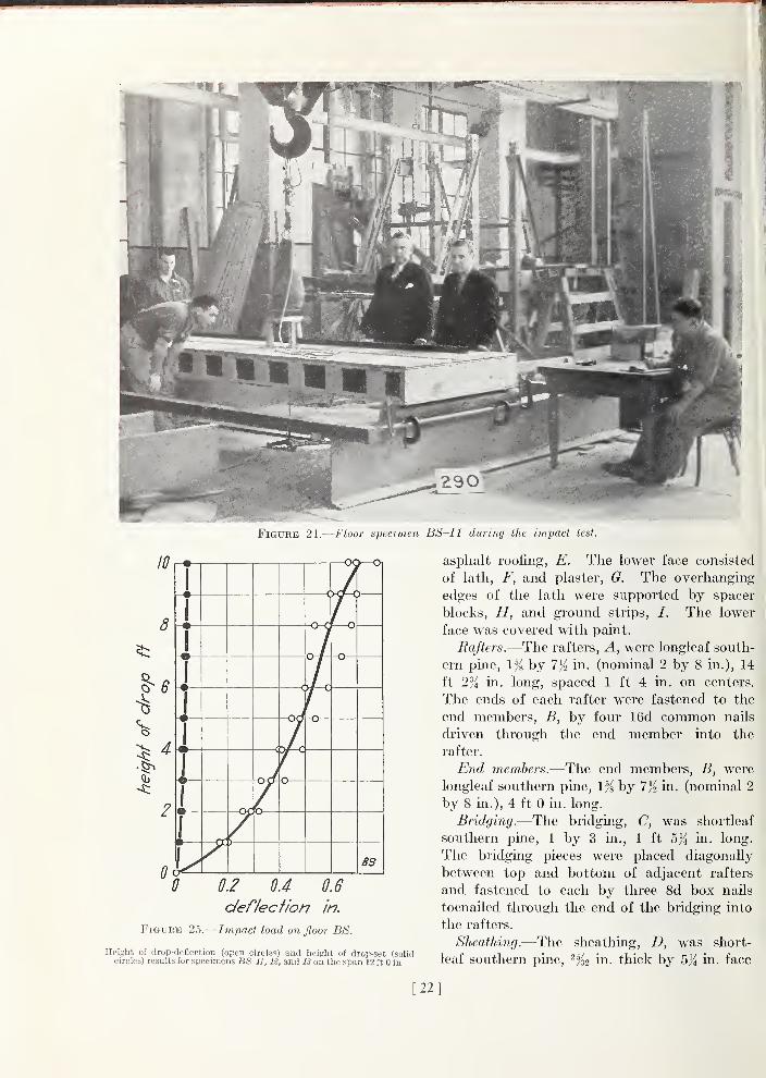
Figure 24.
—
Floor specimen BS~I1 during the impact test.
0 0.2 0.4 0.6
deflecfion in.
Figure 25.
—
Impact load on floor BS.
Height of drop-deflection (open circle'i) and height ol drop-set (solidcircles) results for specimens BS-Il, 12, and IS on the span 12 ft 0 in.
asphalt roofing, E. The lower face consisted
of lath, F, and plaster, G. The overhanging
edges of the lath were supported by spacer
blocks, H, and ground strips, /. The lower
face was covered with paint.
Rafters.—The rafters, A, were longleaf south-
ern pine, 1% by 7/2 in. (nominal 2 by 8 in.), 14
ft 2% in. long, spaced 1 ft 4 in. on centers.
The ends of each rafter were fastened to the
end members, B, by four 16d common naUs
driven through the end member into the
rafter.
End members.—The end members, B, were
longleaf southern pine, 1% by 7)2 in- (nominal 2
by 8 in.), 4 ft 0 in. long.
Bridging.—The bridging, C, was sliortleaf
southern pine, 1 by 3 in., 1 ft b){ in. long.
The bridging pieces were placed diagonally
between top and bottom of adjacent rafters
and fastened to each by three 8d box nails
toenailed through the end of the bridging into
the rafters.
Sheathing.—The sheathing, D, was short-
leaf southern pine, in. thick by 5% in. face
[22]
width (nominal 1 by 6 in.), tongued-and-
grooved on sides and fastened transversely
acpss the rafters by 8d box naUs; two nails
were driven through each piece into each rafter
and into the end members, for those pieces which
were in contact with them.
Asphalt roofing.—The roofing, E, was three-
ply built-up roofing. The first ply was 30-lb
asphalt-saturated felt in strips 36 in. wide, laid
over the sheathing across the rafters with a
at the joint. The lath was fastened to the
rafters by l}^-in. plasterboard nails, five nails
to each course at each rafter; and to each endmember by five nails, one nail at each rafter
and at each end of the member.Sj)acer blocks.—The spacer blocks, H, were
shortleaf southern pine, ^•^2 by 6^'K2 in., 6 in.
long, and siipported the overhanging edges of
the lath. The blocks were centered at the
joints between lath courses, and rested on
Figure 26.
—
Roof specimen BT.
A, rafter; B, end member; C, bridging; D, sheathing: E. asphalt roofing; F, lath; G, plaster; H, spacer block; /, ground strip.
2-ui. overlap, and fastened to the sheathing
by 1-in. roofing nails, with roofing caps under
the heads, spaced 7 in. along the laps and 12 in.
along the longitudinal edges of the specimen.
After mopping down with 30 lb of asphalt per
100 ft^, 15-lb felt strips, 36 in. wide, were laid
over this ply, with a 19-in. transverse overlap,
thus forming two additional plies. Each 15-lb
strip was mopped down with 30 lb of asphalt
per 100 ft^ before placing the next strip. Thefinished roofing thus consisted of three thick-
nesses of asphalt-saturated felt, each covered
with an asphalt coating.
iai/i,.—The lath, F, consisted of "RedStripe" lath, ten full courses and one course cut
to 1 ft 2 in. The lath was applied with no
clearance between courses and with a longi-
tudinal joint in most courses, centered on a
rafter, with no clearance between lath boards
gromid strips. The blocks were fastened to
the ground strips and the sheatliing by 8d box
nails, two nails tlu'ough the groimd strips or
sheathing into each block.
Gr-ound strips.—The groimd strips, /, were
shortleaf southern pine, ^^^2 by 1% in., 14 ft
2% m. long. The lath was fastened to the
ground strips by 1%-ux. plasterboard nails, five
nads for each course driven through the lath
into the ground strip. The ground strips were
cut at every lath course just before the specimen
was tested so that they did not affect the
strength of the specimen. These groimd strips
and spacer blocks are not used in a house.
Plaster.—The plaster, G, was % in. thick andconsisted of a base coat and a finish coat. Thelath was dry when the plaster was applied.
Paint.—The lower face was prepared for
painting by the application of one coat of size,
[23]
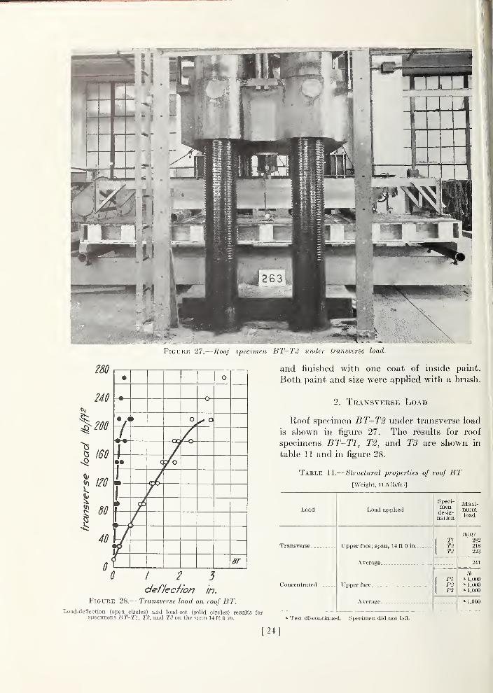
Figure 27.
—
UwJ specimen UT-TJ uiakr transverse load.
280
240
\200
CO
I
//^
40
0
• o
• —O-
» O
4-••
I-
^7'
and finished witii one coat of inside paint.
Botli paint and size were applied witli a brusli.
2. Transverse Load
Roof specimen BT-T2 under transverse load
is shown in figure 27. The results for roof
specimens BT-Tl, T2, and T3 are shown in
table 11 and in figure 28.
Table 11.
—
Structural properties of roof BT[Weight, 11.5 lb/ft 2]
Load
Transverse-
0 12 5
deflecfion in.
Figure 28.
—
Transverse load on roof BT.Load-deflection (open circles) aDd load-set (solid circles) results for
specimens BT-Tl, T2, and T3 on the span 14 ft 0 in.
Concentrated-
Load applied
Upper face; span, 14 ft 0 in-
Average
Upper face
Average.
Speci-mendesig-nation
TlT2TS
PIPtPS
Maxi-mumload
Ib/m282218223
241
lb
» 1,000' 1,000» 1,000
' 1,000
Test discontinued. Specimen did not fail.
24
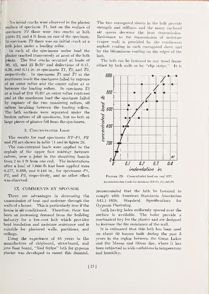
No initial cracks were observed in the plaster
surface of specimen Tl, but on the surface of
specimen T2 there were two cracks at lath
joints 2)^ and 4 ft from an end of the specimen.
In specimen T3 there was an initial crack at a
lath joint under a loading- roller.
In each of the specimens under load the
plaster cracked transversely at most of the lath
joints. The first cracks occurred at loads of
30, 45, and 23 Ib/ft^ and deflections of 0.17,
0.36, and 0.11 in. in specimens Tl, T2, and TS,
respectively. In specimens Tl and T2 at the
maximum loads the specimens failed by rupture
of an outer rafter and the center rafter at or
between the loading rollers. In specimen T3at a load of 210 lb/ft ^ an outer rafter ruptured
and at the maximum load the specimen failed
by rupture of the two remaining rafters, all
rafters breaking between the loading rollers.
The lath sections were separated under the
broken rafters of all specimens, but no lath or
large pieces of plaster fell from the specimens.
3. Concentrated Load
The results for roof specimens BT-Pl, P2and P3 are shown in table 1 1 and in figure 29.
The concentrated loads were applied to the
asphalt of the upper face midway between
rafters, over a joint in the sheathing boards
from 2 to 3 ft from one end. The indentations
after a load of 1,000 lb had been applied were
0.277, 0.389, and 0.446 in., for specimens PI,
P2, and PS, respectively, and no other effect
was observed.
IX. COMMENTS BY SPONSOR
There are advantages in decreasing the
transmission of heat and moisture through the
walls of a house. This is particiilarly true if the
house is air-conditioned. Therefore, there has
been an increasing demand from the building
industry for a low-cost lath which provides
heat insulation and moisture resistance and is
suitable for plastered walls, partitions, andceilings.
Using the experience of 45 years in the
manufacture of chipboard, strawboard, and
jute liner board, "Red Stripe" lath for gypsumplaster was developed to meeet this demand.
The two corrugated sheets in the lath providestrength and stifiness and the many enclosedair spaces decrease the heat transmission.
Resistance to the trnjisinission of moisture(vapor seal) is provided by the conthiuousasphalt coating in each corrugated sheet andby the bituminous coating on the edges of tlie
lath.
The lath can be fastened to any wood frameeither by lath nails or by "clip strips." It is
mo
800
J 600
o
^200
—w
—
1 J »i/—
^
—i
—
<
1
—
»
—
/
1
—
•
—
/
•
—
—
I
•
—
•
—
—•-
—
•
•
L>
—
i
7/ BT
Q 0.1 0.2 0.5
indenfahon in.
04
Figure 29.
—
Concentrated load on roof BT.
Load-indentation results for specimens BT-Pl, P2, and PS.
recommended that the lath be fastened to
comply with American Standards Association
A42. 1-1938, Standard Specifications for
Gypsum Plastering.
Lath having holes uniformly spaced over the
surface is available. The holes provide a
mechanical key for the plaster and are designed
to increase the fire resistance of the wall.
It is estimated that this lath has been used
on about 60 houses built during the past 3
years in the region between the Great Lakes
and the Mason and Dixon line, where it has
been subjected to wide variations in temperature
and humidity.
[25]
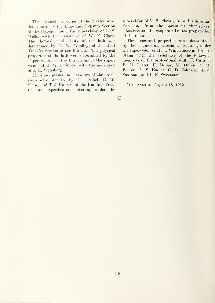
The physical properties of the plaster were
determined by the Lime and Gypsum Section
of the Bureau, under the supervision of L. S.
Wells, with the assistance of W. F. Clark.
The thermal conductivity of the lath was
determined by H. W. WooUey, of the Heat
Transfer Section of the Bureau. The physical
properties of the lath were determined by the
Paper Section of the Bureau under the super-
vision of B. W. Scribner, with the assistance
of S. G. Weissberg.
The descriptions and drawings of the speci-
mens were prepared by E. J. Schell, G. W.Shaw, and T. J. Hanley, of the Building Prac-
tice and Specifications Section, xmder the
supervision of V. B. Phelan, from this informa-
tion and from the specimens themselves.
That Section also cooperated in the preparation
of the report.
The structural properties were determined
by the Engineering Mechanics Section, under
the supervision of H. L. Whittemore and A. H.Stang, with the assistance of the following
members of the professional staff: F. Cardile,
R. C. Carter, H. Dollar, M. Dubin, A. H.Easton, A. S. Endler, C. D. Johnson, A. J.
Sussman, and L. R. Sweetman.
Washington, August 18, 1939.
o
[26]
BUILDING MATERIALS AND STRUCTURES REPORTS
On request, the Superintendent of Documents, U. S. Government Printing Office, Washington,D. C, will place your name on a special mailing list to receive notices of new reports in thisseries as soon as they are issued. There will be no charge for receiving such notices.
An alternative method is to deposit with the Superintendent of Documents the sum of $5,with the request that the reports be sent to you as soon as issued, and that the cost thereof becharged against your deposit. This will provide for the maihng of the publications withoutdelay. You will be notified when the amount of your deposit has become exhausted.If 100 copies or more of any paper are ordered at one time, a discount of 25 percent is allowed.
Send all orders and remittances to the Superintendent of Documents, U. S. Government PrintingOffice, Washington, D. C.
The following publications in this series are now available by purchase from the
Superintendent of Documents at the prices indicated:
BMSl Research on Building Materials and Structures for Use in Low-Cost Housing lOji
BMS2 Methods of Determining the Structural Properties of Low-Cost House Constructions.. 10^BMS3 Suitability of Fiber Insulating Lath as a Plaster Base 10^5
BMS4 Accelerated Aging of Fiber Building Boards 10j5
BMS5 Structural Properties of Six Masonry WaU Constructions 15(4
BMS6 Survey of Roofing Materials in the Southeastern States 15^BMS7 Water Permeability of Masonry Walls 10^BMS8 Methods of Investigation of Surface Treatment for Corrosion Protection of Steel 10(4
BMS9 Structural Properties of the Insulated Steel Construction Company's "Frameless-Steel"Constructions for Walls, Partitions, Floors, and Roofs lOji
BMSIO Structural Properties of One of the "Keystone Beam Steel Floor" Constructions Spon-sored by the H. H. Robertson Co 10(4
BMSll Structural Properties of the Curren Fabrihome Corporation's "Fabrihome" Construc-tions for Walls and Partitions 10^
BMS12 Structural Properties of "Steelox" Constructions for Walls, Partitions, Floors, and RoofsSponsored by Steel Buildings, Inc 150
BMS13 Properties of Some Fiber Building Boards of Current Manufacture 10^BMS14 Indentation and Recovery of Low-Cost Floor Coverings 10^BMS15 Structural Properties of "Wheeling Long-Span Steel Floor" Construction Sponsored by
the Wheeling Corrugating Co 100BMS16 Structural Properties of a "Tilecrete" Floor Construction Sponsored by Tilecrete Floors,
Inc 10(4
BMS17 Sound Insulation of Wall and Floor Constructions 100BMS18 Structural Properties of "Pre-Fab" Constructions for Walls, Partitions, and Floors
Sponsored by the Harnischfeger Corporation 100BMS19 Preparation and Revision of Building Codes 150BMS20 Structural Properties of "Twachtman" Constructions for Walls and Floors Sponsored by
Connecticut Pre-Cast Buildings Corporation 100BMS21 Structural Properties of a Concrete-Block Cavity-Wall Construction Sponsored by the
National Concrete Masonry Association 100BMS22 Structural Properties of "Dun-Tl-Stone" Wall Construction Sponsored by the W. E.
Dunn Manufacturing Co 100BMS23 Structural Properties of a Brick Cavity-Wall Construction Sponsored by the Brick
Manufacturers Association of New York, Inc 100BMS24 Structural Properties of a Reinforced-Brick WaU Construction and a Brick-Tile Cavity-
Wall Construction Sponsored by the Structural Clay Products Institute 100BMS25 Structural Properties of Conventional Wood-Frame Constructions for Walls, Partitions,
Floors, and Roofs 150BMS26 Structural Properties of "Nelson Pre-Cast Concrete Foundation" Wall Construction
Sponsored by the Nelson Cement Stone Co., Inc 100BMS27 Structural Properties of "Bender Steel Home" Wall Construction Sponsored by The
Bender Body Co 100BMS28 Backflow Prevention in Over-Rim Water Supplies 100BMS29 Survey of Roofing Materials in the Northeastern States 100BMS30 Structural Properties of a Wood-Frame Wall Construction Sponsored by the Douglas
Fir Plywood Association 100BMS31 Structural Properties of "Insulite" WaU and "Insulite" Partition Constructions Spon-
sored by the Insulite Co 150BMS32 Structural Properties of Two Brick-Concrete-Block Wall Constructions and a Con-
crete-Block Wall Construction Sponsored by the National Concrete MasonryAssociation 100
BMS35 Stability of Sheathing Papers as Determined by Accelerated Aging 100BMS36 Structural Properties of Wood-Frame Wall, Partition, Floor, and Roof Constructions
with "Red Stripe" Lath Sponsored by the Weston Paper and Manufacturing Co. 100


![3B—{‡ ]Bt˝—Bj V}}—Bs{Y › ~tims › pubs › IEEETRA2000Zhu.pdf3B—{‡ ]Bt˝—Bj V}}—Bs{Y ... s—‡ ; † ˚](https://img.pdfslide.net/doc/110x75/60d7d15f0a006b6e6740a4c8/3baa-btabj-vabsy-a-tims-a-pubs-a-3baa-btabj-vabsy.jpg)