Embed Size (px)
Citation preview

National Center for Computational Hydroscience and Engineering
The University of Mississippi
Wave Model of CCHE2D-CoastFor Model Training Course
Yan Ding, Ph.D.
Research Assistant ProfessorNational Center for Computational Hydroscience and Engingeering
The University of Mississippi, Oxford, MS 38677
March, 2008

Deformation of Irregular Waves
Deformation of waves from offshore to onshore
• Shoaling
• Refraction
• Diffraction
• Reflection
• Wave Breaking
• Wave Transmission through structure
• Bottom Friction
• Wave-Current Interaction
•……
Incid
ent W
ave
Wave Transmission through a Nonsubmerged Structure
Wave transmission coefficient Kt= Hr/Hf
Transmission through and over a riprap structure
Hr = Wave height transmitted to the water body in the rear side of the structureHf = Wave height in front of the structure
Overtopping
Kt can be determined by means of the experimental studies on the features of structures; The values can be found from most of coastal textbooks and coastal engineering manuals

Irregular Wave Models
• Phase-averaged models1. Short-wave-averaged models dealing with irregular and
multidirectional waves developed on a statistical basis;2. Spectral Energy Balance Equation (SEB);3. The models can predict irregular wave transformation in a large-
scale region (1-100km), but not time-varying wave conditions
• Phase-resolving models1. Simulate the time-varying processes of short waves, and even
wave breaking process; 2. It’s suitable for small region and can give highly spatial
resolutions.

Multidirectional Wave Spectral Model (1)
• Energy Balance Equation + Diffraction The variations of wave energy density S(x,y,,f) under the
attack of irregular/multi-directional incident waves, can be represented as follows, (Mase 2001)
wave ray
shoreline
x
y
2
222 cos
2
1cos
2 y
SCC
y
SCC
yQ
Sv
y
Sv
x
Svgg
yx
where = wave direction (-0.5 – 0.5), v = energy transport velocity, Q = source term arisen from energy dissipation, e.g., wave breaking and bottom friction. = empirical coefficient (=2.0-3.0). C=wave celerity, Cg=wave group celerity
Diffraction Term
Fig. Coordinate System
y
C
x
C
C
CvCvCv g
gygx cossinsin,cos

f
S(f)
o fp
Wave Spectrum S(f,θ) and Wave Properties
D NarrowBroad
O
( , ) ( ) ( , )S f S f D f
/ 2
0 / 20
1( , )S f dfd
m
S(f)= Wave Frequency SpectrumD(θ,f)= Wave Directional Spreading Function
• Multidirectional Wave Spectrum Energy
• Significant Wave Height H1/3 Based on the Rayleigh Distribution
0
2
mT
m
/ 2
0 0 / 2( , )m S f dfd
1/3 04.0H m
• Total Wave Energy
• Mean Wave Direction
• Averaged Wave Period

Wave Spectral Model (2)Frequency Spectra S(f)
• Bretschneider-Mitsuyasu (1970) (B-M Spectrum)
• Texel Marsen Arsole (TMA) Spectrum (Bouws et al. 1985)
43/1
543/1
23/1 )(
05.1exp257.0)(
fTfTHfS
),(2
)(expln25.1exp
)2()(
22
24
54
2
hff
ff
f
f
f
gfS
p
pp
h=water depthfp=peak frequency= peak enhancement factor
21
21)2(5.01
1)(5.0
),( 2
2
h
hh
hh
for
for
for
hf
2/1)/(2 ghfh
ff
ff p
09.0
07.0
f
S(f)
o fp
D NarrowBroad
O
• Bretschneider-Mitsuyasu (B-M) Spectrum
• Texel Marsen Arsole (TMA) Spectrum (Bouws et al. 1985)
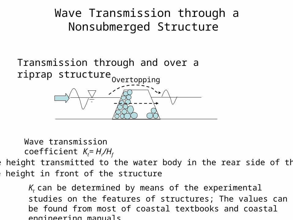
Wave Spectral Model (3)Directional Spreading Function D(q,f)
2cos),( 2
0
sGfD
J
jmm jjfD
1
2 )(cos)(5.0exp1
2
1),(
cedisdecaylongwithswellfor
cedisdecayshortwithswellfor
waveswindfor
S
tan75
tan25
10
max
)1(
)1(2 212
0
s
sG
s
ffsff
ffsffs
p
pp
max5.2max
5
)(
)(
m=mean wave direction; J=number of terms in the series (=20)m= spreading parameter

Wave Breaking Criteria
• Goda’s Criterion (Goda 1975)
)151(5.1exp(1 3/4
00
L
hA
L
Hb
Hb = Breaking Wave HeightL0 = Wave LengthA = Empirical Coefficient (0.12 – 0.18) = Sea Bed Slope
• Saturated Wave Breaking
bH hh = water depth γ = empirical coefficient, 0.6-0.8

Generation of Non-Orthogonal Mesh Covering Touchien Estuary
CCHE2D Mesh Generator
http://www.ncche.olemiss.edu/index.php?page=freesoftware#mesh

Close-up View of Mesh

Wave Spectrum Input
x
y
Onshore
Offshore
+θ
-θ
Offshore wave spectral properties:
Wave height (m)Period (s)Mean Direction (Deg)Tide Elevation (m)

Input Data (1)
Filename = *_wave.dat, where * = a project name, e.g. touchien
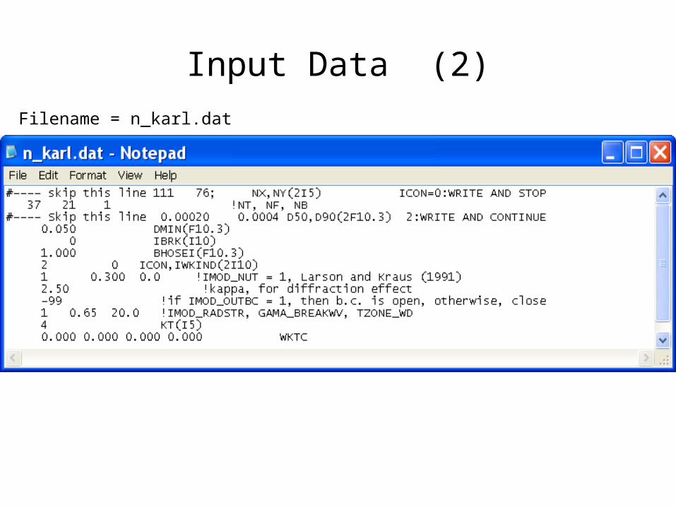
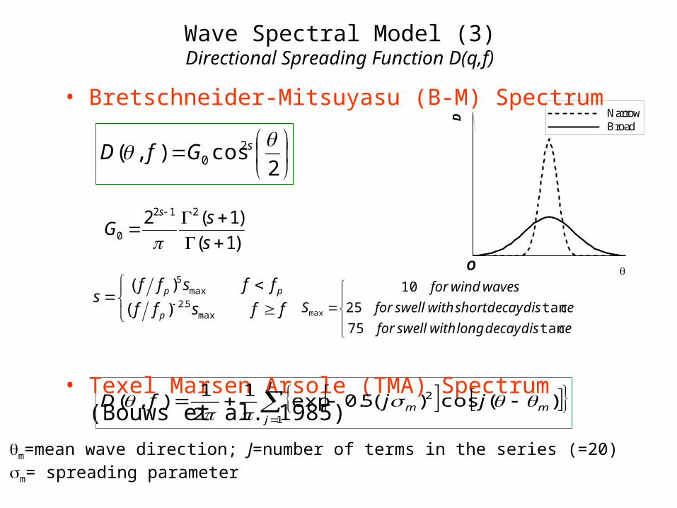
Input Data (2)
Filename = n_karl.dat

OutputFilename = wave_res.plt
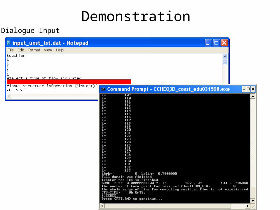
Demonstration Dialogue Input

Contact Information
Yan Ding, Ph.DNational Center for Computational Hydroscience and EngineeringThe University of MississippiCarrier Hall, Room 102University, MS 38677U.S.A.
Email: [email protected]: +1 (662) 915-1339Website: http://www.ncche.olemiss.edu