Embed Size (px)
Citation preview

© Copyright 1994 National Instruments Corporation.All Rights Reserved.
SC-2040User Manual
Eight-Channel Simultaneous Sample-and-Hold Accessory
September 1994 Edition
Part Number 371191A-01

National Instruments Corporate Headquarters6504 Bridge Point ParkwayAustin, TX 78730-5039(512) 794-0100Technical support fax: (800) 328-2203
(512) 794-5678
Branch Offices:Australia (03) 879 9422, Austria (0662) 435986, Belgium 02/757.00.20, Canada (Ontario) (519) 622-9310,Canada (Québec) (514) 694-8521, Denmark 45 76 26 00, Finland (90) 527 2321, France (1) 48 14 24 24,Germany 089/741 31 30, Italy 02/48301892, Japan (03) 3788-1921, Netherlands 03480-33466, Norway 32-848400,Spain (91) 640 0085, Sweden 08-730 49 70, Switzerland 056/20 51 51, U.K. 0635 523545
Limited Warranty
The SC-2040 is warranted against defects in materials and workmanship for a period of one year from the date ofshipment, as evidenced by receipts or other documentation. National Instruments will, at its option, repair or replaceequipment that proves to be defective during the warranty period. This warranty includes parts and labor.
A Return Material Authorization (RMA) number must be obtained from the factory and clearly marked on theoutside of the package before any equipment will be accepted for warranty work. National Instruments will pay theshipping costs of returning to the owner parts which are covered by warranty.
National Instruments believes that the information in this manual is accurate. The document has been carefullyreviewed for technical accuracy. In the event that technical or typographical errors exist, National Instrumentsreserves the right to make changes to subsequent editions of this document without prior notice to holders of thisedition. The reader should consult National Instruments if errors are suspected. In no event shall NationalInstruments be liable for any damages arising out of or related to this document or the information contained in it.
EXCEPT AS SPECIFIED HEREIN, NATIONAL INSTRUMENTS MAKES NO WARRANTIES, EXPRESS OR IMPLIED,AND SPECIFICALLY DISCLAIMS ANY WARRANTY OF MERCHANTABILITY OR FITNESS FOR A PARTICULARPURPOSE. CUSTOMER'S RIGHT TO RECOVER DAMAGES CAUSED BY FAULT OR NEGLIGENCE ON THE PARTOF NATIONAL INSTRUMENTS SHALL BE LIMITED TO THE AMOUNT THERETOFORE PAID BY THE CUSTOMER.NATIONAL INSTRUMENTS WILL NOT BE LIABLE FOR DAMAGES RESULTING FROM LOSS OF DATA, PROFITS,USE OF PRODUCTS, OR INCIDENTAL OR CONSEQUENTIAL DAMAGES, EVEN IF ADVISED OF THE POSSIBILITYTHEREOF. This limitation of the liability of National Instruments will apply regardless of the form of action,whether in contract or tort, including negligence. Any action against National Instruments must be brought withinone year after the cause of action accrues. National Instruments shall not be liable for any delay in performance dueto causes beyond its reasonable control. The warranty provided herein does not cover damages, defects,malfunctions, or service failures caused by owner's failure to follow the National Instruments installation, operation,or maintenance instructions; owner's modification of the product; owner's abuse, misuse, or negligent acts; andpower failure or surges, fire, flood, accident, actions of third parties, or other events outside reasonable control.
Copyright
Under the copyright laws, this publication may not be reproduced or transmitted in any form, electronic ormechanical, including photocopying, recording, storing in an information retrieval system, or translating, in wholeor in part, without the prior written consent of National Instruments Corporation.
Trademarks
LabVIEW®, NI-DAQ®, and RTSI® are trademarks of National Instruments Corporation.
Product names and company names listed are trademarks or trade names of their respective companies.

Warning Regarding Medical and Clinical Useof National Instruments Products
National Instruments products are not designed with components and testing intended to ensure a level of reliabilitysuitable for use in treatment and diagnosis of humans. Applications of National Instruments products involvingmedical or clinical treatment can create a potential for accidental injury caused by product failure, or by errors onthe part of the user or application designer. Any use or application of National Instruments products for or involvingmedical or clinical treatment must be performed by properly trained and qualified medical personnel, and alltraditional medical safeguards, equipment, and procedures that are appropriate in the particular situation to preventserious injury or death should always continue to be used when National Instruments products are being used.National Instruments products are NOT intended to be a substitute for any form of established process, procedure, orequipment used to monitor or safeguard human health and safety in medical or clinical treatment.
© National Instruments Corporation v SC-2040 User Manual
Contents
About This Manual................................................................................................................ ixOrganization of This Manual ............................................................................................ ixConventions Used in This Manual....................................................................................xThe National Instruments Documentation Set..................................................................xRelated Documentation ....................................................................................................xiCustomer Communication ................................................................................................xi
Chapter 1Introduction .......................................................................................................................... 1-1
About the SC-2040.........................................................................................................1-1What You Need to Get Started ......................................................................................1-1Software Programming Choices ....................................................................................1-2
LabVIEW and LabWindows Application Software ..........................................1-2NI-DAQ Driver Software...................................................................................1-2Register-Level Programming.............................................................................1-4
Optional Equipment .......................................................................................................1-4Unpacking ......................................................................................................................1-4
Chapter 2Configuration and Installation....................................................................................... 2-1
Board Configuration ......................................................................................................2-1Supplementary Configuration Information........................................................2-6
Power Supply Selection .........................................................................2-6Shield Selection......................................................................................2-6DAQ Board Ground Isolation Selection ................................................2-6
Gain Selection....................................................................................................2-6Input Mode Selection.........................................................................................2-7
Installation......................................................................................................................2-8Power On Sequence .......................................................................................................2-8
Chapter 3Signal Connections ............................................................................................................. 3-1
I/O Connector Pin Description.......................................................................................3-1Signal Connection Description ..........................................................................3-4Analog Signal Input ...........................................................................................3-7
DC-Coupled Inputs ................................................................................3-7AC-Coupled Signals ..............................................................................3-8
Analog Input Ranges..................................................................3-10Digital Signal Input............................................................................................3-11Monitoring Signal Outputs.................................................................................3-11
Other Connection Considerations ..................................................................................3-11
Contents
SC-2040 User Manual vi © National Instruments Corporation
Chapter 4Theory of Operation .......................................................................................................... 4-1
Functional Overview......................................................................................................4-1Analog Circuitry ............................................................................................................4-3
Input Protection..................................................................................................4-3Amplification .....................................................................................................4-3Track-and-Hold (T/H) Circuitry ........................................................................4-3
Triggering from the DAQ Board ...........................................................4-4External Triggering................................................................................4-5Output Connection .................................................................................4-6Power Supply .........................................................................................4-6
Chapter 5Calibration Procedures.....................................................................................................5-1
Software Calibration ......................................................................................................5-1Offset Adjustment..............................................................................................5-1Gain Adjustment ................................................................................................5-2Linearity Adjustment .........................................................................................5-2
Hardware Calibration.....................................................................................................5-2
Appendix ASpecifications ........................................................................................................................ A-1
Appendix BCustomer Communication............................................................................................... B-1
Glossary ........................................................................................................................Glossary-1
Index ..................................................................................................................................Index-1
Contents
© National Instruments Corporation vii SC-2040 User Manual
Figures
Figure 1-1. The Relationship between the Programming Environment,NI-DAQ, and Your Hardware............................................................................. 1-3
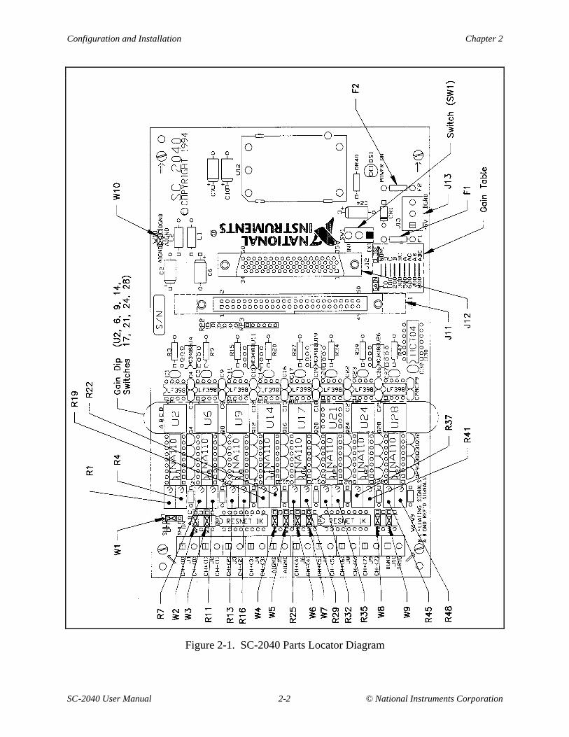
Figure 2-1. SC-2040 Parts Locator Diagram..........................................................................2-2
Figure 3-1. SC-2040 I/O Connectors J11 and J12..................................................................3-2Figure 3-2. SC-2040 Signal Routing......................................................................................3-6Figure 3-3. Ground-Referenced Signal Connection...............................................................3-7Figure 3-4. Floating Signal Connection .................................................................................3-8Figure 3-5. Ground-Referenced AC-Coupled Signal Connection .........................................3-9Figure 3-6. Ground-Offset AC-Coupled Signal Connection..................................................3-9Figure 3-7. Floating AC-Coupled Signal Connection............................................................3-10
Figure 4-1. SC-2040 Block Diagram......................................................................................4-2Figure 4-2. T/H Amplifier Hold Settling Time and Track Acquisition Time........................4-4Figure 4-3. MIO-16E Controlled Triggering..........................................................................4-5Figure 4-4. External Triggering..............................................................................................4-6
Tables
Table 2-1. Power Supply Selection.......................................................................................2-3Table 2-2. Shield Selection ...................................................................................................2-4Table 2-3. DAQ Board Ground Isolation Selection..............................................................2-4Table 2-4. Channel Gain Selection .......................................................................................2-5Table 2-5. Channel Input Mode ............................................................................................2-5Table 2-6. Gain Switches for Each Channel .........................................................................2-6Table 2-7. Switch Settings for Gain Selection......................................................................2-7Table 2-8. Input Mode Selection Jumpers ............................................................................2-7
Table 3-1. Pin Assignments for Connectors J11 and J12......................................................3-3Table 3-2. Input Connectors Signal Summary......................................................................3-4Table 3-3. Output Connectors (J11 and J12) Signal Summary.............................................3-4
Table 5-1. Calibration Component Identification.................................................................5-3
© National Instruments Corporation ix SC-2040 User Manual
About This Manual
This manual describes the electrical and mechanical aspects of the SC-2040 and containsinformation concerning its configuration and operation. The SC-2040 is an eight-channelsimultaneously sampling differential amplifier for the National Instruments MIO-16E SeriesDAQ boards. The SC-2040 samples all eight channels at the same time, preserving interchannelphase relationships for the MIO-16E.
Organization of This Manual
The SC-2040 User Manual is organized as follows:
• Chapter 1, Introduction, describes the SC-2040, lists what you need to get started with yourSC-2040, describes the optional software and optional equipment, and explains how tounpack your SC-2040.
• Chapter 2, Configuration and Installation, describes the configuration and installation ofyour SC-2040. The topics discussed are switch and jumper configuration, connection of theSC-2040 to the MIO-16E, and the power-on sequence for your SC-2040 configuration.
• Chapter 3, Signal Connections, describes the signal connections to the SC-2040 board, andcable wiring.
• Chapter 4, Theory of Operation, contains a functional overview of the SC-2040 board andexplains the operation of each functional unit making up the SC-2040.
• Chapter 5, Calibration Procedures, discusses the calibration procedures for the SC-2040board.
• Appendix A, Specifications, lists the specifications for the SC-2040.
• Appendix B, Customer Communication, contains forms you can use to request help fromNational Instruments or to comment on our products.
• The Glossary contains an alphabetical list and description of terms used in this manual,including abbreviations, acronyms, metric prefixes, mnemonics, and symbols.
• The Index contains an alphabetical list of key terms and topics used in this manual, includingthe page where you can find each one.
About This Manual
SC-2040 User Manual x © National Instruments Corporation
Conventions Used in This Manual
The following conventions are used in this manual:
bold italic Bold, italic text denotes a note, caution, or warning.
italic Italic text denotes emphasis, a cross reference, or an introduction to a keyconcept.
MIO-16E MIO-16E refers to the National Instruments E-Series of MIO-16 DAQboards unless otherwise noted.
monospace Lowercase text in this font denotes text or characters that are to be literallyinput from the keyboard, sections of code, programming examples, andsyntax examples. This font is also used for the proper names of diskdrives, paths, directories, programs, subprograms, subroutines, devicenames, functions, variables, filenames, and extensions, and for statementsand comments taken from program code.
Abbreviations, acronyms, metric prefixes, mnemonics, symbols, and terms are listed in theGlossary.
The National Instruments Documentation Set
The SC-2040 User Manual is one piece of the documentation set for your system. You couldhave any of several types of manuals, depending on the hardware and software in your system.Use the manuals you have as follows:
• Your DAQ hardware user manuals–These manuals have detailed information about the DAQhardware that plugs into or is connected to your computer. Use these manuals for hardwareinstallation and configuration instructions, specification information about your DAQhardware, and application hints.
• Software manuals–Examples of software manuals you might have are the LabVIEW andLabWindows® manual sets and the NI-DAQ manuals. After you set up your hardwaresystem, use either the application software (LabVIEW or LabWindows) manuals or theNI-DAQ manuals to help you write your application. If you have a large and complicatedsystem, it is worthwhile to look through the software manuals before you configure yourhardware.
• Accessory manuals–If you are using accessory products, read the terminal block and cableassembly installation guides or accessory board user manuals. They explain how tophysically connect the relevant pieces of the system together. Consult these guides when youare making your connections.
About This Manual
© National Instruments Corporation xi SC-2040 User Manual
Related Documentation
The following document contains information that you may find helpful as you read this manual:
• Your DAQ hardware user manual
Customer Communication
National Instruments wants to receive your comments on our products and manuals. We areinterested in the applications you develop with our products, and we want to help if you haveproblems with them. To make it easy for you to contact us, this manual contains comment andconfiguration forms for you to complete. These forms are in Appendix B, CustomerCommunication, at the end of this manual.
© National Instruments Corporation 1-1 SC-2040 User Manual
Chapter 1Introduction
This chapter describes the SC-2040, lists what you need to get started with your SC-2040,describes the optional software and optional equipment, and explains how to unpack yourSC-2040.
About the SC-2040
The SC-2040 is an eight-channel simultaneously sampling differential amplifier for the NationalInstruments MIO-16E Series DAQ boards. Each channel provides DIP-switch-selectable gainfollowed by a track-and-hold amplifier. The track-and-hold amplifiers sample all the inputs atthe same time, which is useful for preserving interchannel phase relationships. The MIO-16Ecan trigger the track-and-hold amplifiers, or you can supply an external trigger source.
Note: When a board is referred to without an AT prefix (that is, MIO-16E), the referenceapplies to the AT versions of that board.
The SC-2040 is a circuitboard assembly that is placed on a workbench or mounted in a 19-in.rack. You can configure the SC-2040 to draw power from the MIO-16E board or from anexternal +5 V supply. A red LED indicates when the board is powered on. Input signal leads areattached at screw terminals.
What You Need to Get Started
To set up and use your SC-2040, you will need the following components:
• SC-2040 board
• SC-2040 User Manual
• 1.0, 2.0, 5.0, or 10.0 m SH6868 or R6868 cable
Detailed specifications of the SC-2040 are in Appendix A, Specifications.
Introduction Chapter 1
SC-2040 User Manual 1-2 © National Instruments Corporation
Software Programming Choices
Your SC-2040 kit does not include software. There are four options to choose from whenprogramming your National Instruments DAQ and SCXI hardware. You can use LabVIEW,LabWindows, NI-DAQ, or register-level programming software.
The SC-2040 works with LabVIEW for Windows, LabVIEW for Macintosh, LabWindows forDOS, LabWindows/CVI for Windows, NI-DAQ software for PC compatibles, and NI-DAQsoftware for Macintosh.
LabVIEW and LabWindows Application Software
LabVIEW and LabWindows are innovative program development software packages for dataacquisition and control applications. LabVIEW uses graphical programming, whereasLabWindows enhances traditional programming languages. Both packages include extensivelibraries for data acquisition, instrument control, data analysis, and graphical data presentation.
LabVIEW currently runs on three different platforms–AT/MC/EISA computers runningMicrosoft Windows, the Macintosh platform, and the Sun SPARCstation platform. LabVIEWfeatures interactive graphics, a state-of-the-art user interface, and a powerful graphicalprogramming language. The LabVIEW Data Acquisition VI Library, a series of VIs for usingLabVIEW with National Instruments DAQ hardware, is included with LabVIEW. TheLabVIEW Data Acquisition VI Libraries are functionally equivalent to the NI-DAQ software,except that the SCXI functions are not included in the LabVIEW software for Sun.
LabWindows has two versions–LabWindows for DOS is for use on PCs running DOS, andLabWindows/CVI is for use on PCs running Windows and for Sun SPARCstations.LabWindows/CVI features interactive graphics, a state-of-the-art user interface, and uses theANSI standard C programming language. The LabWindows Data Acquisition Library, a seriesof functions for using LabWindows with National Instruments DAQ hardware, is included withthe NI-DAQ software kit. The LabWindows Data Acquisition libraries are functionallyequivalent to the NI-DAQ software, except that the SCXI functions are not included in theLabWindows/CVI software for Sun.
Using LabVIEW or LabWindows software will greatly reduce the development time for yourdata acquisition and control application.
NI-DAQ Driver Software
The NI-DAQ driver software is included at no charge with all National Instruments DAQhardware. NI-DAQ is not packaged with SCXI or accessory products. NI-DAQ has anextensive library of functions that you can call from your application programming environment.These functions include routines for analog input (A/D conversion), buffered data acquisition(high-speed A/D conversion), analog output (D/A conversion), waveform generation, digital I/O,counter/timer operations, SCXI, RTSI, self-calibration, messaging, and acquiring data toextended memory.
Chapter 1 Introduction
© National Instruments Corporation 1-3 SC-2040 User Manual
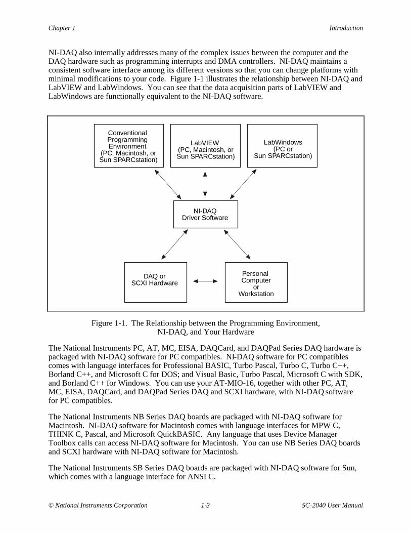
NI-DAQ also internally addresses many of the complex issues between the computer and theDAQ hardware such as programming interrupts and DMA controllers. NI-DAQ maintains aconsistent software interface among its different versions so that you can change platforms withminimal modifications to your code. Figure 1-1 illustrates the relationship between NI-DAQ andLabVIEW and LabWindows. You can see that the data acquisition parts of LabVIEW andLabWindows are functionally equivalent to the NI-DAQ software.
LabWindows(PC or
Sun SPARCstation)
LabVIEW (PC, Macintosh, orSun SPARCstation)
Conventional Programming Environment
(PC, Macintosh, orSun SPARCstation)
NI-DAQDriver Software
DAQ orSCXI Hardware
Personal Computer
orWorkstation
Figure 1-1. The Relationship between the Programming Environment,NI-DAQ, and Your Hardware
The National Instruments PC, AT, MC, EISA, DAQCard, and DAQPad Series DAQ hardware ispackaged with NI-DAQ software for PC compatibles. NI-DAQ software for PC compatiblescomes with language interfaces for Professional BASIC, Turbo Pascal, Turbo C, Turbo C++,Borland C++, and Microsoft C for DOS; and Visual Basic, Turbo Pascal, Microsoft C with SDK,and Borland C++ for Windows. You can use your AT-MIO-16, together with other PC, AT,MC, EISA, DAQCard, and DAQPad Series DAQ and SCXI hardware, with NI-DAQ softwarefor PC compatibles.
The National Instruments NB Series DAQ boards are packaged with NI-DAQ software forMacintosh. NI-DAQ software for Macintosh comes with language interfaces for MPW C,THINK C, Pascal, and Microsoft QuickBASIC. Any language that uses Device ManagerToolbox calls can access NI-DAQ software for Macintosh. You can use NB Series DAQ boardsand SCXI hardware with NI-DAQ software for Macintosh.
The National Instruments SB Series DAQ boards are packaged with NI-DAQ software for Sun,which comes with a language interface for ANSI C.
Introduction Chapter 1
SC-2040 User Manual 1-4 © National Instruments Corporation
Register-Level Programming
There are no register-level programming concerns for the SC-2040. When using the SC-2040,only the MIO-16E Series board needs to be programmed. Refer to your MIO-16E board manualfor further information on register-level programming.
Optional Equipment
Contact National Instruments to order the following optional equipment:
• CB-50 I/O connector (50-screw terminals) with 0.5 or 1.0 m cable
• Single or double height rack-mount kit with acrylic plastic cover
• Single or double height rack-mount kit with metal wraparound cover
Unpacking
Your SC-2040 board is shipped in an antistatic package to prevent electrostatic damage to theboard. Electrostatic discharge can damage several components on the board. To avoid suchdamage in handling the board, take the following precautions:
• Ground yourself via a grounding strap or by holding a grounded chassis such as a computerchassis.
• Touch the antistatic package to a metal part of your computer chassis before removing theboard from the package.
• Remove the board from the package and inspect the board for loose components or any othersign of damage. Notify National Instruments if the board appears damaged in any way.Do not install a damaged board into your computer.
• Never touch the exposed pins of connectors.
© National Instruments Corporation 2-1 SC-2040 User Manual
Chapter 2Configuration and Installation
This chapter describes the configuration and installation of your SC-2040. The topics discussedare switch and jumper configuration, connection of the SC-2040 to the MIO-16E, and the power-on sequence for your SC-2040 configuration.
Board Configuration
The SC-2040 has 10 jumpers, eight DIP switches, and one slide switch that you use to configurethe board. These switches and jumpers are shown in Figure 2-1.
Configuration and Installation Chapter 2
SC-2040 User Manual 2-2 © National Instruments Corporation
Figure 2-1. SC-2040 Parts Locator Diagram
Chapter 2 Configuration and Installation
© National Instruments Corporation 2-3 SC-2040 User Manual
The SC-2040 has one switch that controls whether the board is powered from an external supplyor from the MIO-16E board. Furthermore, two jumpers control how the board is shielded andgrounded. Additionally, there are eight sets of switches and jumpers that configure the gainsettings and input modes of the eight SC-2040 channels.
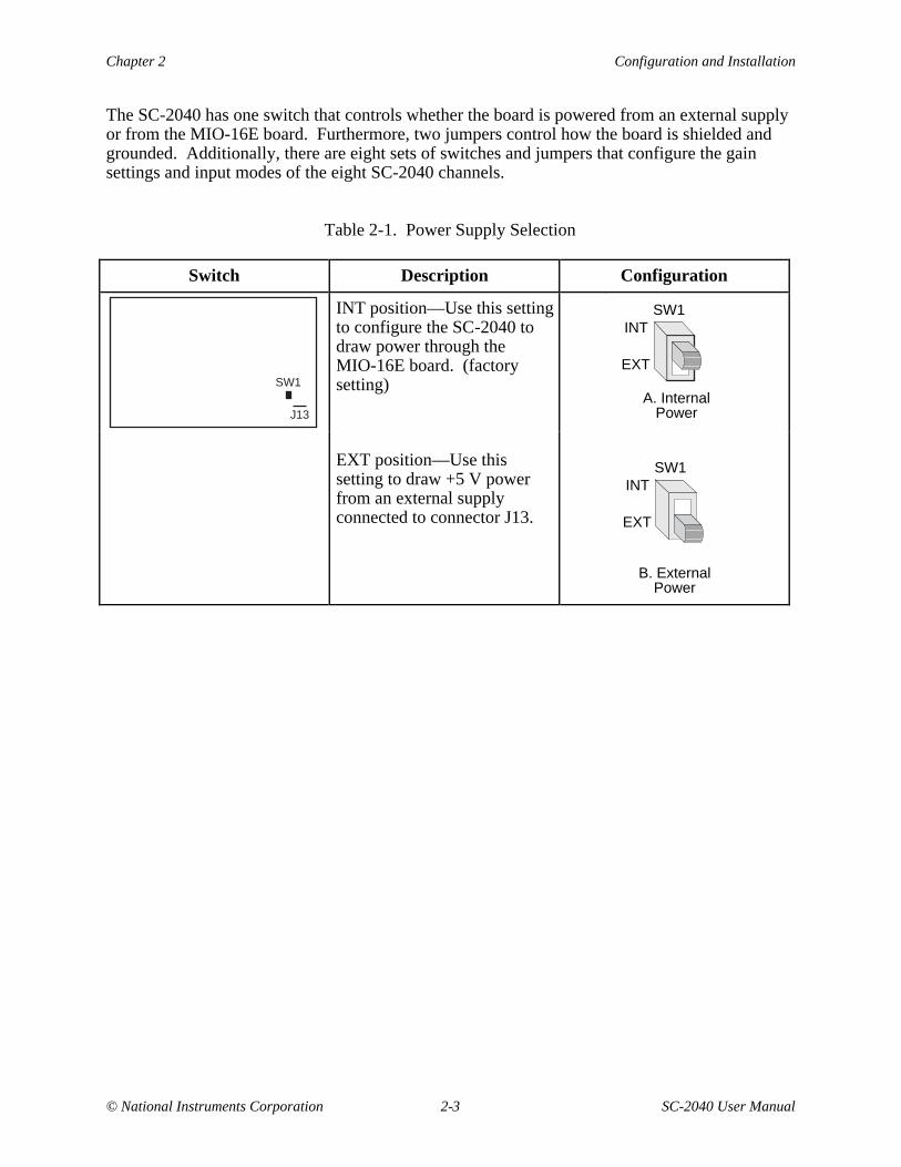
Table 2-1. Power Supply Selection
Switch Description Configuration
SW1
J13
INT position—Use this settingto configure the SC-2040 todraw power through theMIO-16E board. (factorysetting)
SW1INT
EXT
A. Internal Power
EXT position—Use thissetting to draw +5 V powerfrom an external supplyconnected to connector J13.
B. External Power
SW1INT
EXT
Configuration and Installation Chapter 2
SC-2040 User Manual 2-4 © National Instruments Corporation
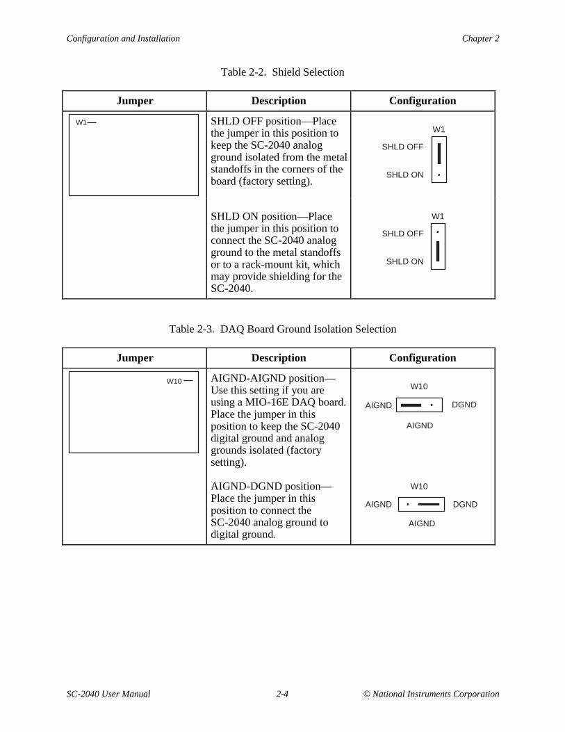
Table 2-2. Shield Selection
Jumper Description Configuration
W1 SHLD OFF position—Placethe jumper in this position tokeep the SC-2040 analogground isolated from the metalstandoffs in the corners of theboard (factory setting).
W1
SHLD OFF
SHLD ON
SHLD ON position—Placethe jumper in this position toconnect the SC-2040 analogground to the metal standoffsor to a rack-mount kit, whichmay provide shielding for theSC-2040.
W1
SHLD OFF
SHLD ON
Table 2-3. DAQ Board Ground Isolation Selection
Jumper Description Configuration
W10 AIGND-AIGND position—Use this setting if you areusing a MIO-16E DAQ board.Place the jumper in thisposition to keep the SC-2040digital ground and analoggrounds isolated (factorysetting).
DGNDAIGND
W10
AIGND
AIGND-DGND position—Place the jumper in thisposition to connect theSC-2040 analog ground todigital ground.
DGNDAIGND
W10
AIGND
Chapter 2 Configuration and Installation
© National Instruments Corporation 2-5 SC-2040 User Manual
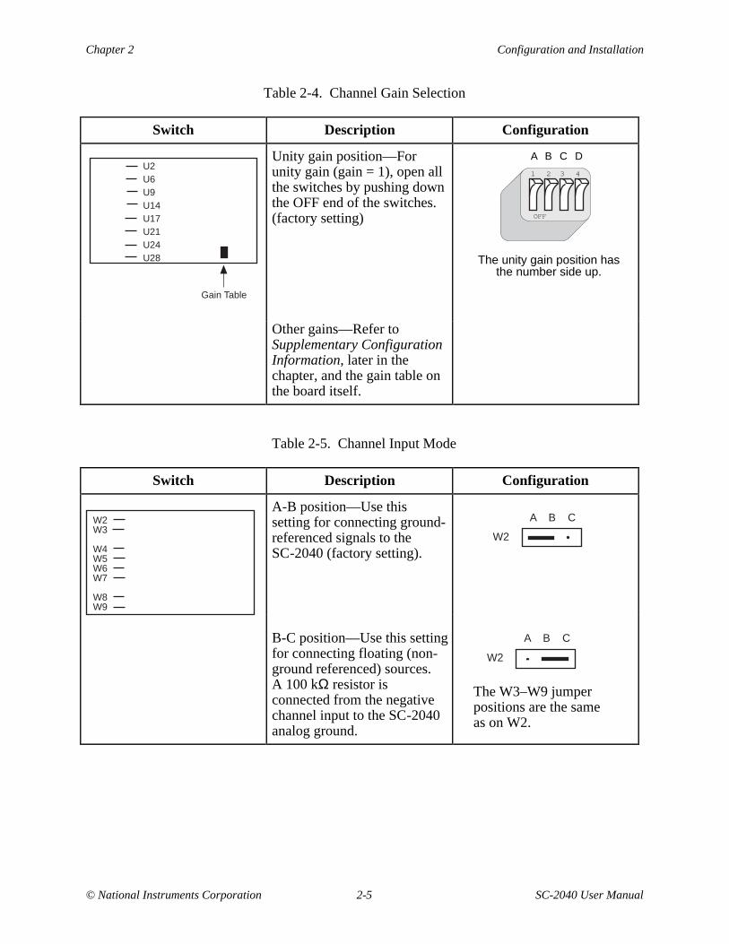
Table 2-4. Channel Gain Selection
Switch Description Configuration
U2U6U9U14U17U21U24U28
Gain Table
Unity gain position—Forunity gain (gain = 1), open allthe switches by pushing downthe OFF end of the switches.(factory setting) OFF
1 2 3 4
The unity gain position has the number side up.
A B C D
Other gains—Refer toSupplementary ConfigurationInformation, later in thechapter, and the gain table onthe board itself.
Table 2-5. Channel Input Mode
Switch Description Configuration
W2W3
W4W5W6W7
W8W9
A-B position—Use thissetting for connecting ground-referenced signals to theSC-2040 (factory setting).
W2
A B C
B-C position—Use this settingfor connecting floating (non-ground referenced) sources.A 100 kΩ resistor isconnected from the negativechannel input to the SC-2040analog ground.
W2
A B C
The W3–W9 jumperpositions are the sameas on W2.
Configuration and Installation Chapter 2
SC-2040 User Manual 2-6 © National Instruments Corporation
Supplementary Configuration Information
Power Supply Selection
Set switch SW1 to the INT position to connect the SC-2040 power converter to the +5 V lines onthe MIO-16E board. Set switch SW1 to the EXT position to draw power from an external +5 Vpower supply connected to J13.
The MIO-16E is fused to provide 5 W of power (at +5 V and 1 A). The SC-2040 consumesnearly all of this available power. Therefore, if you have other DAQ accessories that you wouldlike to power from the MIO, you should switch the SC-2040 to external power and provide anexternal +5 V power source. In external power mode, the SC-2040 is fuse limited to 1 A at+5 V.
Shield Selection
If you are using a rack-mount kit, shield the SC-2040 from unwanted noise by connecting theanalog ground on the board to the metal chassis of the rack using jumper W1. When you set W1to the SHLD ON position, the jumper connects the analog ground to the metal standoffs used tomount the board in a rack. In the SHLD OFF position, the SC-2040 analog ground is isolatedfrom the metal standoffs.
DAQ Board Ground Isolation Selection
You can use jumper W10 to connect the SC-2040 digital and analog grounds. If you are using aMIO-16E board, you must isolate the grounds by leaving the jumper in its default position.
Gain Selection
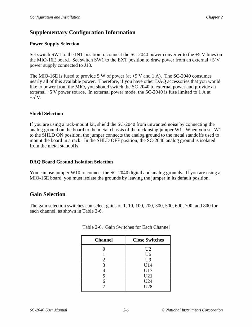
The gain selection switches can select gains of 1, 10, 100, 200, 300, 500, 600, 700, and 800 foreach channel, as shown in Table 2-6.
Table 2-6. Gain Switches for Each Channel
Channel Close Switches
0 U21 U62 U93 U144 U175 U216 U247 U28
Chapter 2 Configuration and Installation
© National Instruments Corporation 2-7 SC-2040 User Manual
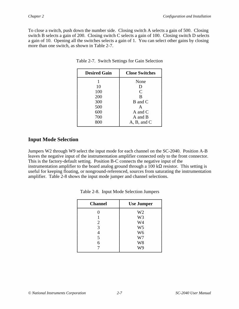
To close a switch, push down the number side. Closing switch A selects a gain of 500. Closingswitch B selects a gain of 200. Closing switch C selects a gain of 100. Closing switch D selectsa gain of 10. Opening all the switches selects a gain of 1. You can select other gains by closingmore than one switch, as shown in Table 2-7.
Table 2-7. Switch Settings for Gain Selection
Desired Gain Close Switches
1 None10 D100 C200 B300 B and C500 A600 A and C700 A and B800 A, B, and C
Input Mode Selection
Jumpers W2 through W9 select the input mode for each channel on the SC-2040. Position A-Bleaves the negative input of the instrumentation amplifier connected only to the front connector.This is the factory-default setting. Position B-C connects the negative input of theinstrumentation amplifier to the board analog ground through a 100 kΩ resistor. This setting isuseful for keeping floating, or nonground-referenced, sources from saturating the instrumentationamplifier. Table 2-8 shows the input mode jumper and channel selections.
Table 2-8. Input Mode Selection Jumpers
Channel Use Jumper
0 W21 W32 W43 W54 W65 W76 W87 W9
Configuration and Installation Chapter 2
SC-2040 User Manual 2-8 © National Instruments Corporation
Installation
Note: You must turn off power to the PC, and to the SC-2040 board if the board is externallypowered, before installing the board or making any connections to it.
To install the SC-2040, connect the 68-pin ribbon from the MIO-16E I/O connector to connectorJ12 on the SC-2040. The SC-2040 can be mounted in a rack-mount chassis using the mountingholes (indicated with an arrow on the board) in the four corners of the SC-2040 board.
The SC-2040 is installed. You are now ready to install and configure your software.
If you are using NI-DAQ, refer to your NI-DAQ manual. The software installation andconfiguration instructions are in Chapter 1, Introduction to NI-DAQ. Find the installation andsystem configuration section for your operating system and follow the instructions given there.
If you are using LabVIEW, the software installation instructions are in your LabVIEW releasenotes. After you have installed LabVIEW, refer to the Configuring LabVIEW section ofChapter 1 of your LabVIEW user manual for software configuration instructions.
If you are using LabWindows, the software installation instructions are in Part 1, Introduction toLabWindows, of the Getting Started with LabWindows manual. After you have installedLabWindows, refer to Chapter 1, Configuring LabWindows, of the LabWindows User Manualfor software configuration instructions.
Power-on Sequence
If the SC-2040 is powered by an external power source, you must turn on power to the SC-2040before turning on the computer. Similarly, you must turn off power to the SC-2040 after turningoff the computer. The red LED labeled DS1 indicates when power is applied to the board.
© National Instruments Corporation 3-1 SC-2040 User Manual
Chapter 3Signal Connections
This chapter describes the signal connections to the SC-2040 board, and cable wiring.
I/O Connector Pin Description
Warning: Connections that exceed any of the maximum ratings of input or output signals onthe MIO-16 can result in damage to the MIO-16 board and to the personalcomputer. This includes connecting any power signals to ground and vice versa.National Instruments is not liable for any damages resulting from any such signalconnections.
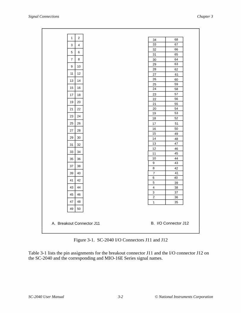
Corresponding signals on connectors J11 and J12 are connected together through the SC-2040.Connector J12 carries the signals to and from the MIO-16E board. Use connector J11 to accessthese signals. You can use this connector to monitor these signals, using a National InstrumentsCB-50, for example, or you can use this connector to connect to other DAQ accessories.Figure 3-1 shows these connectors.
Signal Connections Chapter 3
SC-2040 User Manual 3-2 © National Instruments Corporation
2
4
6
8
10
12
14
16
18
20
22
24
26
28
30
32
34
36
38
40
42
44
46
48
50
1
3
5
7
9
11
13
15
17
19
21
23
25
27
29
31
33
35
37
39
41
43
45
47
49
A. Breakout Connector J11 B. I/O Connector J12
3433
32
31
3029
28
27
26
2524
23
22
21
2019
18
17
16
15
14
13
12
11
10 9
8
6 7
5
4
3
2
1 35
36
37
38
39
40
41
42
4344
45
46
47
48
49
50
51
52
5354
55
56
57
58
59
60
61
62
6364
65
66
67
68
Figure 3-1. SC-2040 I/O Connectors J11 and J12
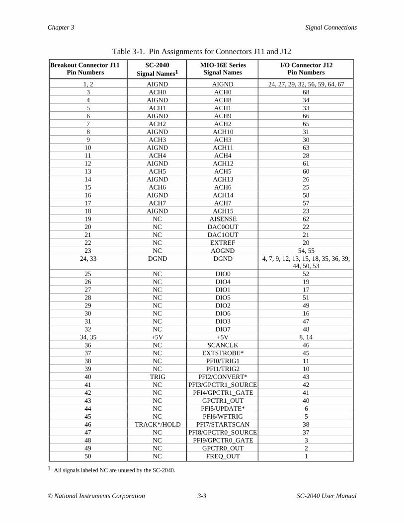
Table 3-1 lists the pin assignments for the breakout connector J11 and the I/O connector J12 onthe SC-2040 and the corresponding and MIO-16E Series signal names.
Chapter 3 Signal Connections
© National Instruments Corporation 3-3 SC-2040 User Manual
Table 3-1. Pin Assignments for Connectors J11 and J12
Breakout Connector J11Pin Numbers
SC-2040Signal Names1
MIO-16E SeriesSignal Names
I/O Connector J12Pin Numbers
1, 2 AIGND AIGND 24, 27, 29, 32, 56, 59, 64, 673 ACH0 ACH0 684 AIGND ACH8 345 ACH1 ACH1 336 AIGND ACH9 667 ACH2 ACH2 658 AIGND ACH10 319 ACH3 ACH3 30
10 AIGND ACH11 6311 ACH4 ACH4 2812 AIGND ACH12 6113 ACH5 ACH5 6014 AIGND ACH13 2615 ACH6 ACH6 2516 AIGND ACH14 5817 ACH7 ACH7 5718 AIGND ACH15 2319 NC AISENSE 6220 NC DAC0OUT 2221 NC DAC1OUT 2122 NC EXTREF 2023 NC AOGND 54, 55
24, 33 DGND DGND 4, 7, 9, 12, 13, 15, 18, 35, 36, 39,44, 50, 53
25 NC DIO0 5226 NC DIO4 1927 NC DIO1 1728 NC DIO5 5129 NC DIO2 4930 NC DIO6 1631 NC DIO3 4732 NC DIO7 48
34, 35 +5V +5V 8, 1436 NC SCANCLK 4637 NC EXTSTROBE* 4538 NC PFI0/TRIG1 1139 NC PFI1/TRIG2 1040 TRIG PFI2/CONVERT* 4341 NC PFI3/GPCTR1_SOURCE 4242 NC PFI4/GPCTR1_GATE 4143 NC GPCTR1_OUT 4044 NC PFI5/UPDATE* 645 NC PFI6/WFTRIG 546 TRACK*/HOLD PFI7/STARTSCAN 3847 NC PFI8/GPCTR0_SOURCE 3748 NC PFI9/GPCTR0_GATE 349 NC GPCTR0_OUT 250 NC FREQ_OUT 1
1 All signals labeled NC are unused by the SC-2040.
Signal Connections Chapter 3
SC-2040 User Manual 3-4 © National Instruments Corporation
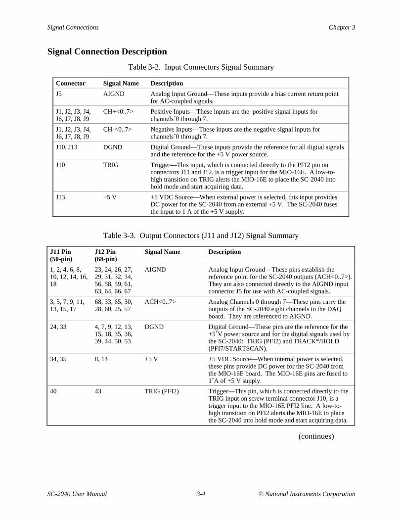
Signal Connection Description
Table 3-2. Input Connectors Signal Summary
Connector Signal Name Description
J5 AIGND Analog Input Ground—These inputs provide a bias current return pointfor AC-coupled signals.
J1, J2, J3, J4,J6, J7, J8, J9
CH+<0..7> Positive Inputs—These inputs are the positive signal inputs forchannels 0 through 7.
J1, J2, J3, J4,J6, J7, J8, J9
CH-<0..7> Negative Inputs—These inputs are the negative signal inputs forchannels 0 through 7.
J10, J13 DGND Digital Ground—These inputs provide the reference for all digital signalsand the reference for the +5 V power source.
J10 TRIG Trigger—This input, which is connected directly to the PFI2 pin onconnectors J11 and J12, is a trigger input for the MIO-16E. A low-to-high transition on TRIG alerts the MIO-16E to place the SC-2040 intohold mode and start acquiring data.
J13 +5 V +5 VDC Source—When external power is selected, this input providesDC power for the SC-2040 from an external +5 V. The SC-2040 fusesthe input to 1 A of the +5 V supply.
Table 3-3. Output Connectors (J11 and J12) Signal Summary
J11 Pin(50-pin)
J12 Pin(68-pin)
Signal Name Description
1, 2, 4, 6, 8,10, 12, 14, 16,18
23, 24, 26, 27,29, 31, 32, 34,56, 58, 59, 61,63, 64, 66, 67
AIGND Analog Input Ground—These pins establish thereference point for the SC-2040 outputs (ACH<0..7>).They are also connected directly to the AIGND inputconnector J5 for use with AC-coupled signals.
3, 5, 7, 9, 11,13, 15, 17
68, 33, 65, 30,28, 60, 25, 57
ACH<0..7> Analog Channels 0 through 7—These pins carry theoutputs of the SC-2040 eight channels to the DAQboard. They are referenced to AIGND.
24, 33 4, 7, 9, 12, 13,15, 18, 35, 36,39, 44, 50, 53
DGND Digital Ground—These pins are the reference for the+5 V power source and for the digital signals used bythe SC-2040: TRIG (PFI2) and TRACK*/HOLD(PFI7/STARTSCAN).
34, 35 8, 14 +5 V +5 VDC Source—When internal power is selected,these pins provide DC power for the SC-2040 fromthe MIO-16E board. The MIO-16E pins are fused to1 A of +5 V supply.
40 43 TRIG (PFI2) Trigger—This pin, which is connected directly to theTRIG input on screw terminal connector J10, is atrigger input to the MIO-16E PFI2 line. A low-to-high transition on PFI2 alerts the MIO-16E to placethe SC-2040 into hold mode and start acquiring data.
(continues)
Chapter 3 Signal Connections
© National Instruments Corporation 3-5 SC-2040 User Manual
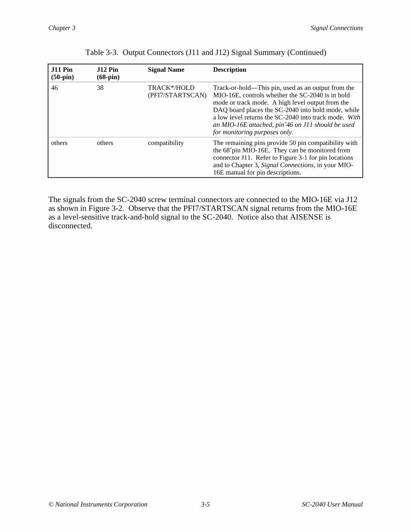
Table 3-3. Output Connectors (J11 and J12) Signal Summary (Continued)
J11 Pin(50-pin)
J12 Pin(68-pin)
Signal Name Description
46 38 TRACK*/HOLD(PFI7/STARTSCAN)
Track-or-hold—This pin, used as an output from theMIO-16E, controls whether the SC-2040 is in holdmode or track mode. A high level output from theDAQ board places the SC-2040 into hold mode, whilea low level returns the SC-2040 into track mode. Withan MIO-16E attached, pin 46 on J11 should be usedfor monitoring purposes only.
others others compatibility The remaining pins provide 50 pin compatibility withthe 68 pin MIO-16E. They can be monitored fromconnector J11. Refer to Figure 3-1 for pin locationsand to Chapter 3, Signal Connections, in your MIO-16E manual for pin descriptions.
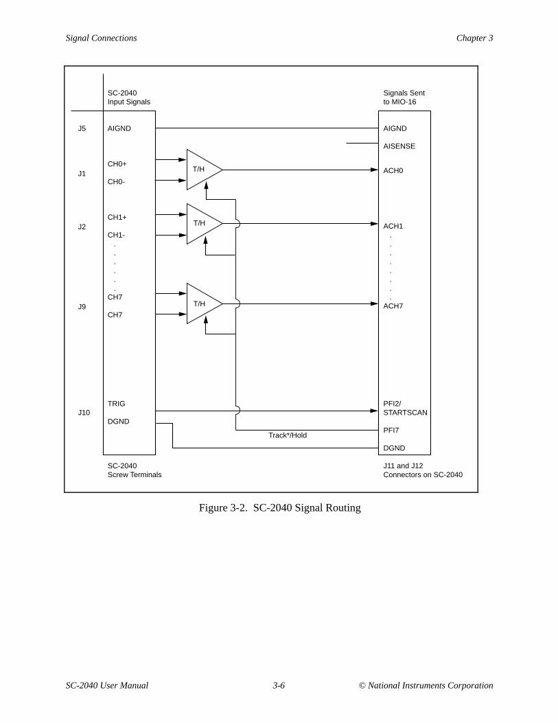
The signals from the SC-2040 screw terminal connectors are connected to the MIO-16E via J12as shown in Figure 3-2. Observe that the PFI7/STARTSCAN signal returns from the MIO-16Eas a level-sensitive track-and-hold signal to the SC-2040. Notice also that AISENSE isdisconnected.
Signal Connections Chapter 3
SC-2040 User Manual 3-6 © National Instruments Corporation
SC-2040Input Signals
AIGND
CH0+
CH0-
CH1+
CH1-......
CH7
CH7
TRIG
DGND
SC-2040Screw Terminals
Signals Sentto MIO-16
AIGND
AISENSE
ACH1........
ACH7
PFI2/STARTSCAN
PFI7
DGND
J11 and J12Connectors on SC-2040
ACH0T/H
T/H
T/H
J5
J1
J2
J9
J10
Track*/Hold
Figure 3-2. SC-2040 Signal Routing
Chapter 3 Signal Connections
© National Instruments Corporation 3-7 SC-2040 User Manual
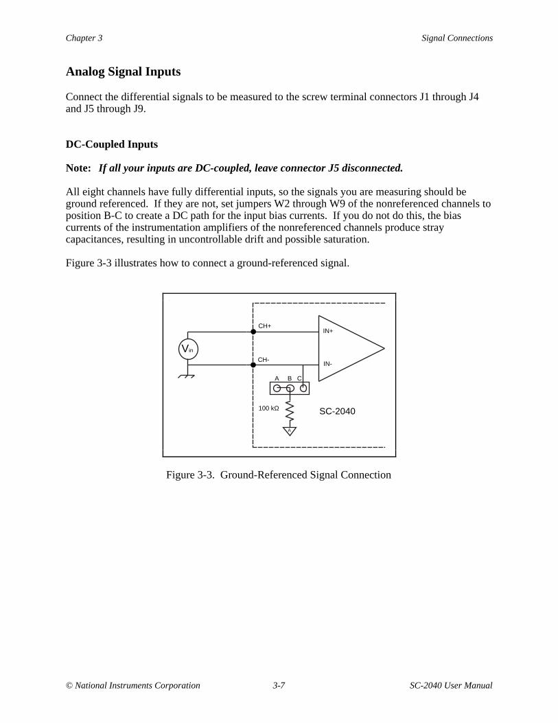
Analog Signal Inputs
Connect the differential signals to be measured to the screw terminal connectors J1 through J4and J5 through J9.
DC-Coupled Inputs
Note: If all your inputs are DC-coupled, leave connector J5 disconnected.
All eight channels have fully differential inputs, so the signals you are measuring should beground referenced. If they are not, set jumpers W2 through W9 of the nonreferenced channels toposition B-C to create a DC path for the input bias currents. If you do not do this, the biascurrents of the instrumentation amplifiers of the nonreferenced channels produce straycapacitances, resulting in uncontrollable drift and possible saturation.
Figure 3-3 illustrates how to connect a ground-referenced signal.
A
IN-
IN+
100 kΩ SC-2040
Vin
A B C
CH+
CH-
Figure 3-3. Ground-Referenced Signal Connection
Signal Connections Chapter 3
SC-2040 User Manual 3-8 © National Instruments Corporation
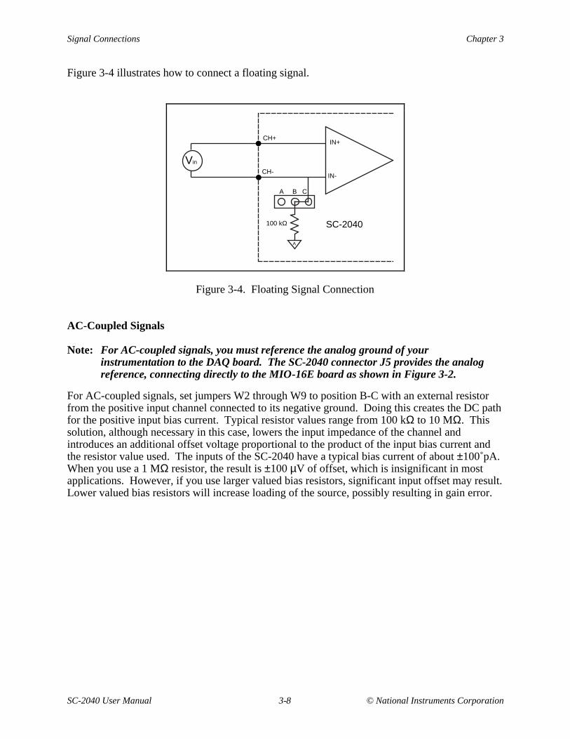
Figure 3-4 illustrates how to connect a floating signal.
IN-
IN+
SC-2040
Vin
CH+
CH-
A
100 kΩ
A B C
Figure 3-4. Floating Signal Connection
AC-Coupled Signals
Note: For AC-coupled signals, you must reference the analog ground of yourinstrumentation to the DAQ board. The SC-2040 connector J5 provides the analogreference, connecting directly to the MIO-16E board as shown in Figure 3-2.
For AC-coupled signals, set jumpers W2 through W9 to position B-C with an external resistorfrom the positive input channel connected to its negative ground. Doing this creates the DC pathfor the positive input bias current. Typical resistor values range from 100 kΩ to 10 MΩ. Thissolution, although necessary in this case, lowers the input impedance of the channel andintroduces an additional offset voltage proportional to the product of the input bias current andthe resistor value used. The inputs of the SC-2040 have a typical bias current of about ±100 pA.When you use a 1 MΩ resistor, the result is ±100 µV of offset, which is insignificant in mostapplications. However, if you use larger valued bias resistors, significant input offset may result.Lower valued bias resistors will increase loading of the source, possibly resulting in gain error.
Chapter 3 Signal Connections
© National Instruments Corporation 3-9 SC-2040 User Manual
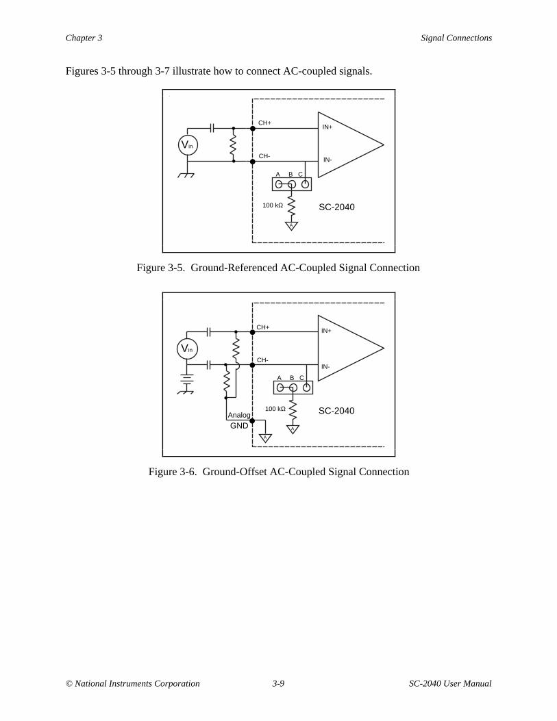
Figures 3-5 through 3-7 illustrate how to connect AC-coupled signals.
IN-
IN+
SC-2040
Vin
CH+
CH-
A
100 kΩ
A B C
Figure 3-5. Ground-Referenced AC-Coupled Signal Connection
IN-
IN+
SC-2040
GNDAnalog
Vin
CH+
CH-
A
100 kΩ
A B C
A
Figure 3-6. Ground-Offset AC-Coupled Signal Connection
Signal Connections Chapter 3
SC-2040 User Manual 3-10 © National Instruments Corporation
IN-
IN+
100 kΩ
Vin
SC-2040
CH+
CH-
A
A B C
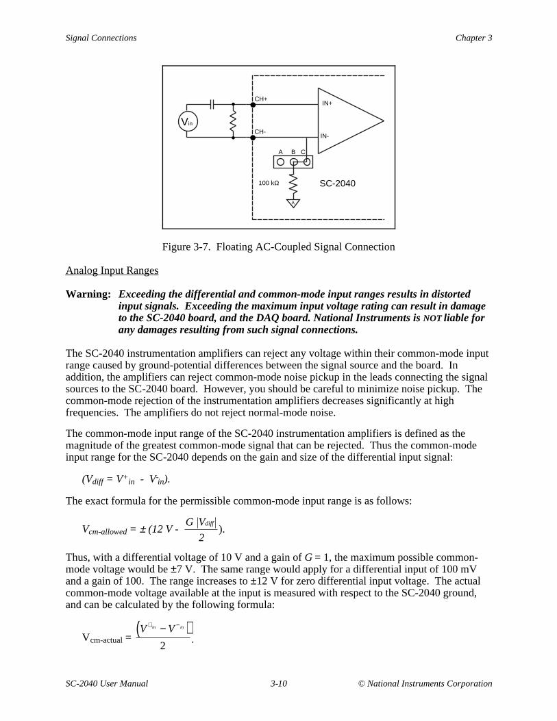
Figure 3-7. Floating AC-Coupled Signal Connection
Analog Input Ranges
Warning: Exceeding the differential and common-mode input ranges results in distortedinput signals. Exceeding the maximum input voltage rating can result in damageto the SC-2040 board, and the DAQ board. National Instruments is NOT liable forany damages resulting from such signal connections.
The SC-2040 instrumentation amplifiers can reject any voltage within their common-mode inputrange caused by ground-potential differences between the signal source and the board. Inaddition, the amplifiers can reject common-mode noise pickup in the leads connecting the signalsources to the SC-2040 board. However, you should be careful to minimize noise pickup. Thecommon-mode rejection of the instrumentation amplifiers decreases significantly at highfrequencies. The amplifiers do not reject normal-mode noise.
The common-mode input range of the SC-2040 instrumentation amplifiers is defined as themagnitude of the greatest common-mode signal that can be rejected. Thus the common-modeinput range for the SC-2040 depends on the gain and size of the differential input signal:
(Vdiff = V+in - V-
in).
The exact formula for the permissible common-mode input range is as follows:
Vcm-allowed = ± (12 V - G Vdiff
2).
Thus, with a differential voltage of 10 V and a gain of G = 1, the maximum possible common-mode voltage would be ±7 V. The same range would apply for a differential input of 100 mVand a gain of 100. The range increases to ±12 V for zero differential input voltage. The actualcommon-mode voltage available at the input is measured with respect to the SC-2040 ground,and can be calculated by the following formula:
Vcm-actual = V + in − V − in( )
2.
Chapter 3 Signal Connections
© National Instruments Corporation 3-11 SC-2040 User Manual
where V+in is the signal at the positive input (IN0+ through IN7+), and V-
in is the signal at thecorresponding negative input (IN0- through IN7-). Both V+
in and V-in are measured with respect
to the SC-2040 chassis ground.
Digital Signal Inputs
If you are using an external trigger, connect the trigger source and the digital reference to screwconnector J9. This signal should be in the range 0 to +5 V, with switching occurring around1.5 V.
Note: All digital signals on the SC-2040 are referenced to the +5 V power supply. If theMIO-16E supplies power, it provides this reference. If an external supply providespower, it provides this reference through connector J13.
A rising edge on the trigger will place the SC-2040 into hold mode, and the SC-2040 will returnto track mode when the MIO-16E indicates that the data acquisition is complete.
Although the TRIG signal is a digital signal, it is still susceptible to noise, particularly at itstransitions. This noise can cause the SC-2040 to enter hold mode on the wrong edge. Twopossible sources of noise are interference and reflection. The best way to reduce noisecorruption is to minimize the distance that the signal must travel. Furthermore, you canminimize interference by properly shielding the incoming trigger signal. You can minimizereflection by ensuring that the impedance of the source of the trigger signal matches theimpedance of the cable used to transmit the signal; inserting a small resistor (about 50 Ω) inseries with the signal source will minimize reflection.
Monitoring Signal Outputs
You can use connector J11 to monitor the signals being sent to and from the MIO-16E board.Figure 4-3 shows a sampled analog signal as the SC-2040 channel output.
You can also monitor the state of the SC-2040 through line PFI7/STARTSCAN. A high level onPFI7/STARTSCAN indicates the SC-2040 is in hold mode, while a low level indicates that theSC-2040 is in track mode.
Other Connection Considerations
Refer to the sections titled Analog Input Signal Connections and Cabling and Field Wiring inChapter 3 of your MIO-16E board user manual for additional signal connection information.
© National Instruments Corporation 4-1 SC-2040 User Manual
Chapter 4Theory of Operation
This chapter contains a functional overview of the SC-2040 board and explains the operation ofeach functional unit making up the SC-2040.
Functional Overview
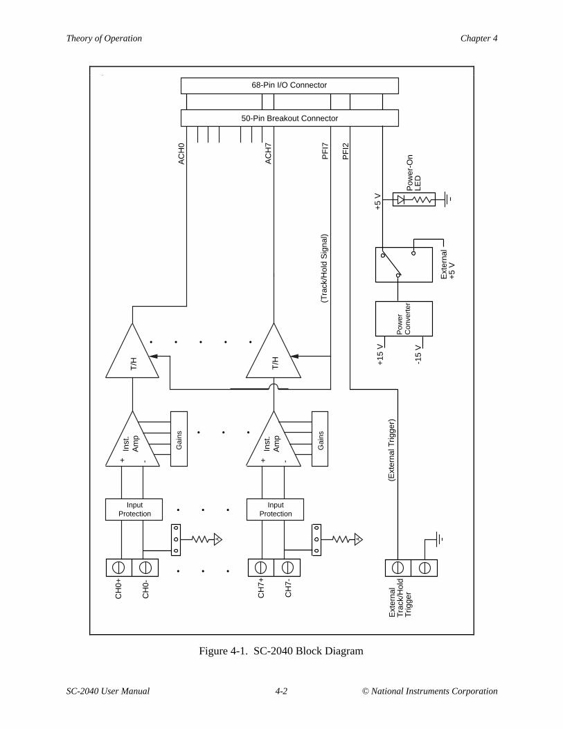
The SC-2040 consists of eight channels, each one comprising an instrumentation amplifier withDIP switch-programmable gains of 1, 10, 100, 200, 300, 500, 600, 700, or 800, and a track-and-hold amplifier. The analog inputs are overvoltage protected. The DAQ board or a user-suppliedexternal trigger switches the SC-2040 between hold mode and track mode as desired. All eightchannels are simultaneously placed in hold mode.
The block diagram in Figure 4-1 illustrates the key functional components of the SC-2040.
Theory of Operation Chapter 4
SC-2040 User Manual 4-2 © National Instruments Corporation
T/H
T/H
InputProtection
InputProtection
+ -
Inst
.A
mp
+ -
Inst
.A
mp
Gai
ns
Gai
ns • • •
• • • • •
• • •
• • •
A A
68-Pin I/O Connector
50-Pin Breakout Connector
AC
H0
AC
H7
PF
I7
PF
I2
(Tra
ck/H
old
Sig
nal)
+5
V+
15 V
-15
VP
ower
-On
LED
Ext
erna
l+
5 V
Pow
er
Con
vert
er
(Ext
erna
l Trig
ger)
Ext
erna
lT
rack
/Hol
dT
rigge
rCH
7+
CH
7-
CH
0-
CH
0+
Figure 4-1. SC-2040 Block Diagram
Chapter 4 Theory of Operation
© National Instruments Corporation 4-3 SC-2040 User Manual
Analog Circuitry
The analog input circuitry consists of eight channels with DIP-switch-programmableinstrumentation amplifiers followed by buffered track-and-hold amplifiers. In addition, you caninclude the voltage-regulation circuitry and input protection in the analog section. Each block isdescribed in the following paragraphs.
Input Protection
The first block an incoming analog signal encounters is the input protection. Each input terminalis protected against input voltages up to ±15 V powered off and ±30 V powered on. The inputprotection consists of a 1 kΩ resistor in series with each input line followed by low-leakagediodes to the supply rails (±15 V).
Amplification
Next in the signal path are the instrumentation amplifiers, which fulfill two purposes on theSC-2040 board. First, the instrumentation amplifiers convert differential input signals intosingle-ended signals referred to the SC-2040 analog ground for input common-mode signalrejection. With this conversion, the SC-2040 can extract the analog input signals from common-mode noise voltages before the DAQ board samples and converts the signals. Second, theinstrumentation amplifiers amplify input signals, resulting in an increase in measurementresolution and accuracy. Furthermore, the amplifiers exhibit low bias currents and goodbandwidth, even at high gains.
You can select gains for each channel independently with separate DIP switches. Gains are 1,10, 100, 200, and 500, although gains of 300, 600, 700, and 800 are available with reducedaccuracy. See Appendix A, Specifications, for details on the performance of the instrumentationamplifiers.
Track-and-Hold (T/H) Circuitry
The track-and-hold amplifiers operate as simple buffers when in track mode, but freeze theiroutputs when placed into hold mode. Because all of the track-and-hold amplifiers in eachSC-2040 board enter hold mode at the same time, they implement simultaneous sampling of allchannels. Simultaneous sampling is useful for preserving phase relationships between channels.
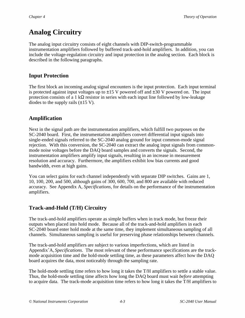
The track-and-hold amplifiers are subject to various imperfections, which are listed inAppendix A, Specifications. The most relevant of these performance specifications are the track-mode acquisition time and the hold-mode settling time, as these parameters affect how the DAQboard acquires the data, most noticeably through the sampling rate.
The hold-mode settling time refers to how long it takes the T/H amplifiers to settle a stable value.Thus, the hold-mode settling time affects how long the DAQ board must wait before attemptingto acquire data. The track-mode acquisition time refers to how long it takes the T/H amplifiers to
Theory of Operation Chapter 4
SC-2040 User Manual 4-4 © National Instruments Corporation
find the inputs again after having been in hold mode. Therefore, this delay indicates how longthe SC-2040 must remain in track mode before it is ready to re-enter hold mode. Returning theSC-2040 to hold mode before the track-mode acquisition delay has elapsed will cause theSC-2040 to "hold" erroneously. Figure 4-2 illustrates these timing concerns. Typical hold modesettling times and track acquisition times for 12-bit and 16-bit accuracies are given inAppendix A, Specifications.
holdtrack holdtrack
track acquisitiontime
hold setting timehold setting time
differential channelinput
T/H output
track*/hold signal(PF17)
Figure 4-2. T/H Amplifier Hold Settling Time and Track Acquisition Time
Triggering from the DAQ Board
This section applies to you only if you are triggering the SC-2040 from the MIO-16E board.
Note: No signal should be connected to connector J10 for MIO-16E triggering.
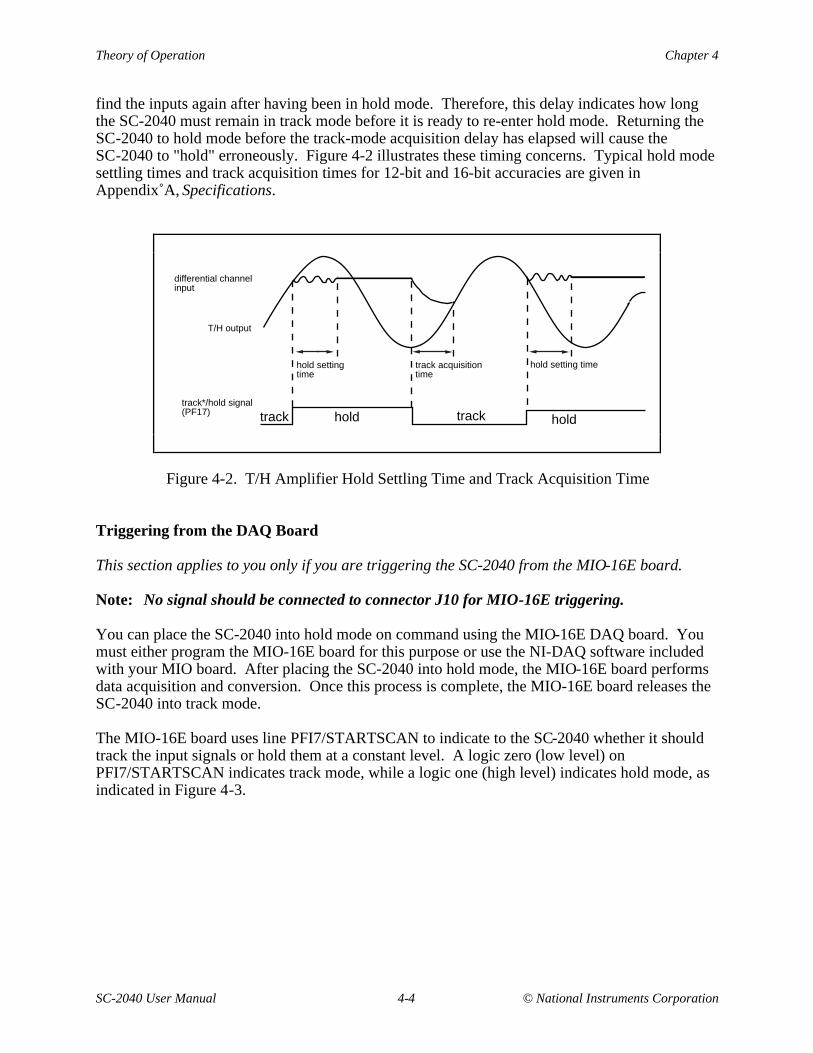
You can place the SC-2040 into hold mode on command using the MIO-16E DAQ board. Youmust either program the MIO-16E board for this purpose or use the NI-DAQ software includedwith your MIO board. After placing the SC-2040 into hold mode, the MIO-16E board performsdata acquisition and conversion. Once this process is complete, the MIO-16E board releases theSC-2040 into track mode.
The MIO-16E board uses line PFI7/STARTSCAN to indicate to the SC-2040 whether it shouldtrack the input signals or hold them at a constant level. A logic zero (low level) onPFI7/STARTSCAN indicates track mode, while a logic one (high level) indicates hold mode, asindicated in Figure 4-3.
Chapter 4 Theory of Operation
© National Instruments Corporation 4-5 SC-2040 User Manual
. . .
. . .
. . .
. . .
. . .
. . .
. . .
. . .
. . .
. . .
. . .
. .
. . .
. . .
. . .
. . .
. . .
. .
. . .
. . .
Differential Channel Input
PFI7 (track*/hold)
SC-2040 Channel Output
hold hold track
tDAQ Conversion t
DAQ Conversion
(DAQ board is scanning)
Figure 4-3. MIO-16E Controlled Triggering
External Triggering
This section applies to you only if you are triggering the board from an external signalconnected to J10.
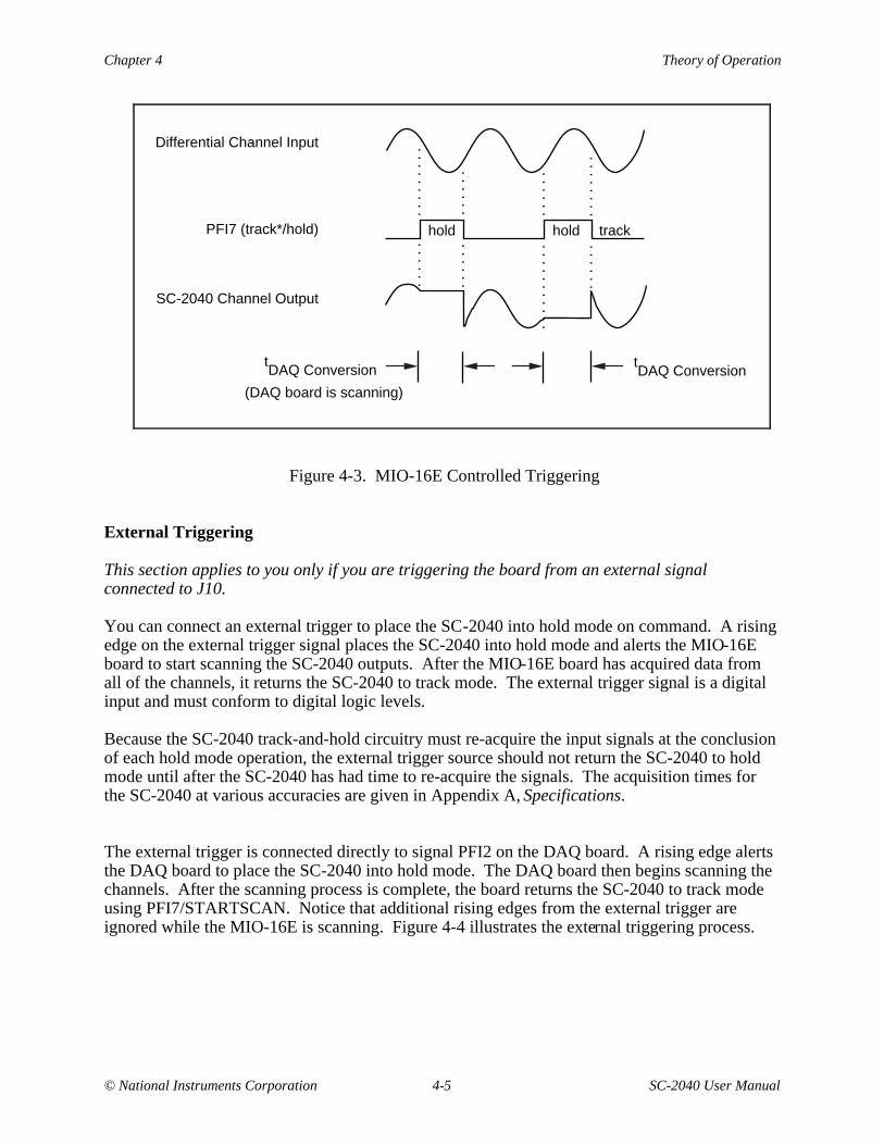
You can connect an external trigger to place the SC-2040 into hold mode on command. A risingedge on the external trigger signal places the SC-2040 into hold mode and alerts the MIO-16Eboard to start scanning the SC-2040 outputs. After the MIO-16E board has acquired data fromall of the channels, it returns the SC-2040 to track mode. The external trigger signal is a digitalinput and must conform to digital logic levels.
Because the SC-2040 track-and-hold circuitry must re-acquire the input signals at the conclusionof each hold mode operation, the external trigger source should not return the SC-2040 to holdmode until after the SC-2040 has had time to re-acquire the signals. The acquisition times forthe SC-2040 at various accuracies are given in Appendix A, Specifications.
The external trigger is connected directly to signal PFI2 on the DAQ board. A rising edge alertsthe DAQ board to place the SC-2040 into hold mode. The DAQ board then begins scanning thechannels. After the scanning process is complete, the board returns the SC-2040 to track modeusing PFI7/STARTSCAN. Notice that additional rising edges from the external trigger areignored while the MIO-16E is scanning. Figure 4-4 illustrates the external triggering process.
Theory of Operation Chapter 4
SC-2040 User Manual 4-6 © National Instruments Corporation
tDAQ Conversion t
DAQ Conversion
. . .
. .
hold holdtrack track
Differential Channel Input
PFI2 (external trigger)
PFI7 (track*/hold)
SC-2040 Channel Output
. . .
. .
. . .
. . .
.
. . .
. . .
. .
. . .
. .
. . .
. .
. . .
. .
. . .
. . .
. .
. . .
. . .
. . .
. . .
. .
. . .
. . .
. . .
(DAQ board is scanning)
Figure 4-4. External Triggering
Output Connection
The output of every channel is connected to the 68-pin rear signal connector and the 50-pinsupplemental I/O connector. The 68-pin connector carries signals to and from the DAQ board,and also provides +5 V power if selected by the power switch. The corresponding pins of the50-pin connector are tied to those of the 68-pin connector so that you can monitor these signalson the 50-pin connector. The pin connections of these connectors are given in Chapter 3, SignalConnections.
Power Supply
The SC-2040 contains an onboard power switch to either power the SC-2040 from the MIO-16Eboard or to draw power from an external +5 V supply. From the +5 V power, an onboardDC-to-DC converter generates a ±15 V source, which is used to power the analog circuitry. Ared LED indicates that the board is receiving power.
© National Instruments Corporation 5-1 SC-2040 User Manual
Chapter 5Calibration Procedures
This chapter discusses the calibration procedures for the SC-2040 board.
Note: In many applications, the SC-2040 factory-hardware calibration is sufficient to meetaccuracy requirements, and no further calibration, either hardware or software, isneeded.
Although hardware calibration is discussed in greater detail than software calibration, softwarecalibration is the preferred choice for the following reasons:
• The calibration adjustments on the SC-2040 are inaccessible under most normal operatingcircumstances.
• With software calibration, the board is calibrated in the exact environment in which it will beoperating. Software calibration compensates for system-introduced, in addition to board-introduced, errors. You can perform software calibration fairly frequently, which helpsreduce drift effects.
Because board-introduced errors are minimal with the SC-2040, the use of software rather thanhardware calibration does not significantly reduce dynamic range. The main drawback ofsoftware calibration is reduced throughput due to the increased processing time.
Software Calibration
Software calibration is very simple. Depending on your accuracy requirements, you may want toperform only offset adjustment; offset and gain adjustments; or offset, gain, and linearityadjustments.
Offset Adjustment
Offset adjustment requires you to apply an input signal of zero to the channel to be calibrated.Zero input can mean shorting the board inputs to zero, or it can mean applying zero excitation tothe transducer being used. In the former case, you can remove only board and DAQ boardoffset; in the latter case, transducer offset is removed as well. In either case, measurements aretaken with the zero input signal. Average these measurements to reduce uncertainty. Thisaverage represents the offset. Next, subtract the offset from all subsequent measurements.Notice that offset changes with gain; thus, during calibration, set the channel to the gain at whichthe subsequent measurements will be taken.
Calibration Procedures Chapter 5
SC-2040 User Manual 5-2 © National Instruments Corporation
Gain Adjustment
Gain adjustment requires you to apply two different input signals. One of the two points istypically zero, because zero is easy to generate with a high degree of accuracy. The other shouldbe near full scale, either a DC-voltage from a precision calibrator or a voltage generated byapplying a known excitation to the transducer being used. Of course, you should generate bothsignals—zero and full scale—from the same source.
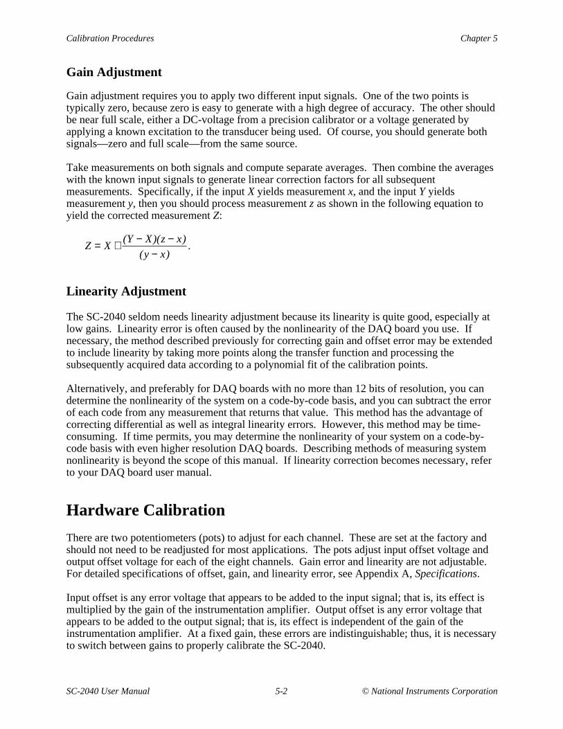
Take measurements on both signals and compute separate averages. Then combine the averageswith the known input signals to generate linear correction factors for all subsequentmeasurements. Specifically, if the input X yields measurement x, and the input Y yieldsmeasurement y, then you should process measurement z as shown in the following equation toyield the corrected measurement Z:
Z = X + (Y − X)(z − x)
(y − x).
Linearity Adjustment
The SC-2040 seldom needs linearity adjustment because its linearity is quite good, especially atlow gains. Linearity error is often caused by the nonlinearity of the DAQ board you use. Ifnecessary, the method described previously for correcting gain and offset error may be extendedto include linearity by taking more points along the transfer function and processing thesubsequently acquired data according to a polynomial fit of the calibration points.
Alternatively, and preferably for DAQ boards with no more than 12 bits of resolution, you candetermine the nonlinearity of the system on a code-by-code basis, and you can subtract the errorof each code from any measurement that returns that value. This method has the advantage ofcorrecting differential as well as integral linearity errors. However, this method may be time-consuming. If time permits, you may determine the nonlinearity of your system on a code-by-code basis with even higher resolution DAQ boards. Describing methods of measuring systemnonlinearity is beyond the scope of this manual. If linearity correction becomes necessary, referto your DAQ board user manual.
Hardware Calibration
There are two potentiometers (pots) to adjust for each channel. These are set at the factory andshould not need to be readjusted for most applications. The pots adjust input offset voltage andoutput offset voltage for each of the eight channels. Gain error and linearity are not adjustable.For detailed specifications of offset, gain, and linearity error, see Appendix A, Specifications.
Input offset is any error voltage that appears to be added to the input signal; that is, its effect ismultiplied by the gain of the instrumentation amplifier. Output offset is any error voltage thatappears to be added to the output signal; that is, its effect is independent of the gain of theinstrumentation amplifier. At a fixed gain, these errors are indistinguishable; thus, it is necessaryto switch between gains to properly calibrate the SC-2040.
Chapter 5 Calibration Procedures
© National Instruments Corporation 5-3 SC-2040 User Manual
Your accuracy needs determine how carefully the offsets need to be calibrated. A typicalrequirement might be for total offset referred to output to be less than half of an LSB of the DAQboard being used. For example, a 12-bit, 20 V system has a resolution of 20 V/212 = 4.88 mV.Calibration to under 2 mV would thus be sufficient for most applications. The SC-2040 isfactory calibrated to have total offset referred to output of less than 2 mV at low gains.
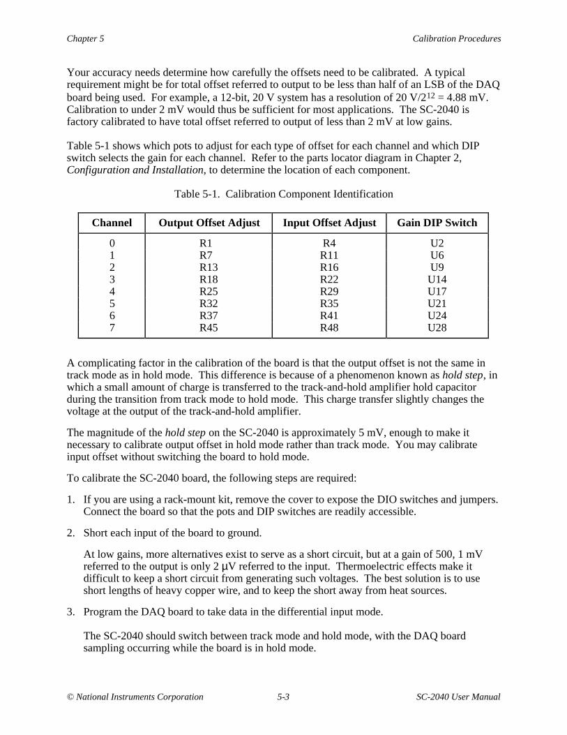
Table 5-1 shows which pots to adjust for each type of offset for each channel and which DIPswitch selects the gain for each channel. Refer to the parts locator diagram in Chapter 2,Configuration and Installation, to determine the location of each component.
Table 5-1. Calibration Component Identification
Channel Output Offset Adjust Input Offset Adjust Gain DIP Switch
0 R1 R4 U21 R7 R11 U62 R13 R16 U93 R18 R22 U144 R25 R29 U175 R32 R35 U216 R37 R41 U247 R45 R48 U28
A complicating factor in the calibration of the board is that the output offset is not the same intrack mode as in hold mode. This difference is because of a phenomenon known as hold step, inwhich a small amount of charge is transferred to the track-and-hold amplifier hold capacitorduring the transition from track mode to hold mode. This charge transfer slightly changes thevoltage at the output of the track-and-hold amplifier.
The magnitude of the hold step on the SC-2040 is approximately 5 mV, enough to make itnecessary to calibrate output offset in hold mode rather than track mode. You may calibrateinput offset without switching the board to hold mode.
To calibrate the SC-2040 board, the following steps are required:
1. If you are using a rack-mount kit, remove the cover to expose the DIO switches and jumpers.Connect the board so that the pots and DIP switches are readily accessible.
2. Short each input of the board to ground.
At low gains, more alternatives exist to serve as a short circuit, but at a gain of 500, 1 mVreferred to the output is only 2 µV referred to the input. Thermoelectric effects make itdifficult to keep a short circuit from generating such voltages. The best solution is to useshort lengths of heavy copper wire, and to keep the short away from heat sources.
3. Program the DAQ board to take data in the differential input mode.
The SC-2040 should switch between track mode and hold mode, with the DAQ boardsampling occurring while the board is in hold mode.
Calibration Procedures Chapter 5
SC-2040 User Manual 5-4 © National Instruments Corporation
4. Set the DAQ board to a high gain and measure its offset by shorting its input.
You must subtract this measured offset from all subsequent board measurements to ensureaccuracy.
For the offset of the DAQ board not to affect the calibration, you must subtract the offsetfrom all board offset measurements. Thus, you must first measure the offset to an accuracybetter than that to which the board is to be calibrated. Furthermore, setting the DAQ board toa high gain (100, for example) makes it possible to resolve offset changes that would beindiscernible at lower gains. Because the DAQ board offset will not be independent of gain,you should set the gain first, and then measure the offset. To measure the offset, disconnectthe board from the DAQ board, short circuit the board inputs to ground, and take some data.The measured value is the offset. For a reliable value, use software to average a few hundredreadings. After you have measured and recorded the offset, remove the short circuits andreconnect the board.
5. Measure the output of the first channel with its gain set to one and adjust its output offset potuntil the output is close to zero.
At this gain, most of the board offset is due to output offset. The input offset adjustment hasminimal effect. Set the DAQ board to read the channel. Acquire the data, averaging as instep 4. Adjust the output offset pot until the difference between the measured offset and theDAQ board offset is close to zero. There is no need to adjust it perfectly because the inputoffset adjustment in the next step might make a slight change in the measured gain-of-oneoffset.
6. Measure the output of the same channel with its gain set to 500 and adjust its input offset potuntil the output is close to zero.
At this gain, the input offset adjustment has the dominant effect. Acquire the data andaverage as before. Adjust the input offset pot until the difference between the measuredoffset and the DAQ board offset is close to zero. Again, it is not necessary to adjust the inputoffset perfectly because there will be a slight interdependence between the two offsets.
7. Repeat step 5, adjusting the offset as carefully as desired. Then repeat step 6, adjusting theoffset as carefully as desired. Switch back to a gain of one to ensure that the low-gain offsetis still calibrated. If necessary, repeat steps 5 and 6 until the offset is calibrated at both gains.
8. Repeat steps 5 through 7 for the additional channels you want to calibrate. There is nocalibration interdependence among the channels.
9. Replace the rack-mount chassis cover, if used.
© National Instruments Corporation A-1 SC-2040 User Manual
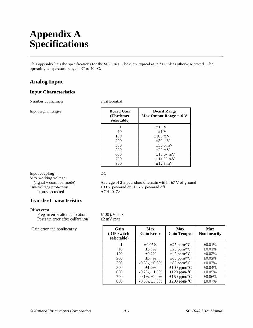
Appendix ASpecifications This appendix lists the specifications for the SC-2040. These are typical at 25° C unless otherwise stated. Theoperating temperature range is 0° to 50° C.
Analog Input
Input Characteristics
Number of channels 8 differential
Input signal ranges Board Gain(HardwareSelectable)
Board RangeMax Output Range ±10 V
1 ±10 V10 ±1 V
100 ±100 mV200 ±50 mV300 ±33.3 mV500 ±20 mV600 ±16.67 mV700 ±14.29 mV800 ±12.5 mV
Input coupling DCMax working voltage
(signal + common mode) Average of 2 inputs should remain within ±7 V of groundOvervoltage protection ±30 V powered on, ±15 V powered off
Inputs protected ACH<0..7>
Transfer Characteristics
Offset errorPregain error after calibration ±100 µV maxPostgain error after calibration ±2 mV max
Gain error and nonlinearity Gain(DIP-switch-selectable)
MaxGain Error
MaxGain Tempco
MaxNonlinearity
1 ±0.05% ±25 ppm/°C ±0.01% 10 ±0.1% ±25 ppm/°C ±0.01%100 ±0.2% ±45 ppm/°C ±0.02%200 ±0.4% ±60 ppm/°C ±0.02%300 -0.3%, ±0.6% ±80 ppm/°C ±0.03%500 ±1.0% ±100 ppm/°C ±0.04%600 -0.2%, ±1.5% ±120 ppm/°C ±0.05%700 -0.1%, ±2.0% ±150 ppm/°C ±0.06%800 -0.3%, ±3.0% ±200 ppm/°C ±0.07%
Specifications Appendix A
SC-2040 User Manual A-2 © National Instruments Corporation
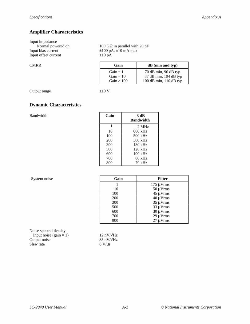
Amplifier Characteristics
Input impedanceNormal powered on 100 GΩ in parallel with 20 pF
Input bias current ±100 pA, ±10 mA maxInput offset current ±10 pA
CMRR Gain dB (min and typ)
Gain = 1 70 dB min, 90 dB typGain = 10 87 dB min, 104 dB typGain ≥ 100 100 dB min, 110 dB typ
Output range ±10 V
Dynamic Characteristics
Bandwidth Gain -3 dBBandwidth
1 2 MHz10 800 kHz
100 500 kHz200 300 kHz300 180 kHz500 120 kHz600 100 kHz700 80 kHz800 70 kHz
System noise Gain Filter1 175 µVrms
10 50 µVrms100 45 µVrms200 40 µVrms300 35 µVrms500 33 µVrms600 30 µVrms700 29 µVrms800 27 µVrms
Noise spectral densityInput noise (gain = 1) 12 nV/√Hz
Output noise 85 nV/√HzSlew rate 8 V/µs
Appendix A Specifications
© National Instruments Corporation A-3 SC-2040 User Manual
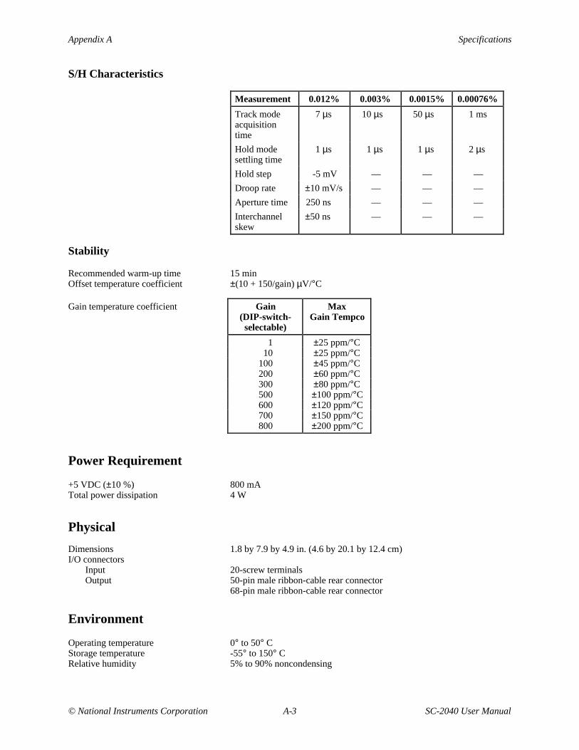
S/H Characteristics
Measurement 0.012% 0.003% 0.0015% 0.00076%
Track modeacquisitiontime
7 µs 10 µs 50 µs 1 ms
Hold modesettling time
1 µs 1 µs 1 µs 2 µs
Hold step -5 mV — — —
Droop rate ±10 mV/s — — —
Aperture time 250 ns — — —
Interchannelskew
±50 ns — — —
Stability
Recommended warm-up time 15 minOffset temperature coefficient ±(10 + 150/gain) µV/°C
Gain temperature coefficient Gain(DIP-switch-selectable)
MaxGain Tempco
1 ±25 ppm/°C 10 ±25 ppm/°C100 ±45 ppm/°C200 ±60 ppm/°C300 ±80 ppm/°C500 ±100 ppm/°C600 ±120 ppm/°C700 ±150 ppm/°C800 ±200 ppm/°C
Power Requirement
+5 VDC (±10 %) 800 mATotal power dissipation 4 W
Physical
Dimensions 1.8 by 7.9 by 4.9 in. (4.6 by 20.1 by 12.4 cm)I/O connectors
Input 20-screw terminalsOutput 50-pin male ribbon-cable rear connector
68-pin male ribbon-cable rear connector
Environment
Operating temperature 0° to 50° CStorage temperature -55° to 150° CRelative humidity 5% to 90% noncondensing

© National Instruments Corporation B-1 SC-2040 User Manual
Appendix BCustomer Communication
For your convenience, this appendix contains forms to help you gather the information necessaryto help us solve technical problems you might have as well as a form you can use to comment onthe product documentation. Filling out a copy of the Technical Support Form before contactingNational Instruments helps us help you better and faster.
National Instruments provides comprehensive technical assistance around the world. In the U.S.and Canada, applications engineers are available Monday through Friday from 8:00 a.m. to6:00 p.m. (central time). In other countries, contact the nearest branch office. You may faxquestions to us at any time.
Corporate Headquarters(512) 795-8248Technical support fax: (800) 328-2203
(512) 794-5678
Branch Offices Phone Number Fax NumberAustralia (03) 879 9422 (03) 879 9179Austria (0662) 435986 (0662) 437010-19Belgium 02/757.00.20 02/757.03.11Denmark 45 76 26 00 45 76 71 11Finland (90) 527 2321 (90) 502 2930France (1) 48 14 24 00 (1) 48 14 24 14Germany 089/741 31 30 089/714 60 35Italy 02/48301892 02/48301915Japan (03) 3788-1921 (03) 3788-1923Netherlands 03480-33466 03480-30673Norway 32-848400 32-848600Spain (91) 640 0085 (91) 640 0533Sweden 08-730 49 70 08-730 43 70Switzerland 056/20 51 51 056/20 51 55U.K. 0635 523545 0635 523154

Technical Support Form
Photocopy this form and update it each time you make changes to your software or hardware, and use the completedcopy of this form as a reference for your current configuration. Completing this form accurately before contactingNational Instruments for technical support helps our applications engineers answer your questions more efficiently.
If you are using any National Instruments hardware or software products related to this problem, include theconfiguration forms from their user manuals. Include additional pages if necessary.
Name
Company
Address
Fax ( ) Phone ( )
Computer brand Model Processor
Operating system
Speed MHz RAM MB Display adapter
Mouse yes no Other adapters installed
Hard disk capacity MB Brand
Instruments used
National Instruments hardware product model Revision
Configuration
National Instruments software product Version
Configuration
The problem is
List any error messages
The following steps will reproduce the problem
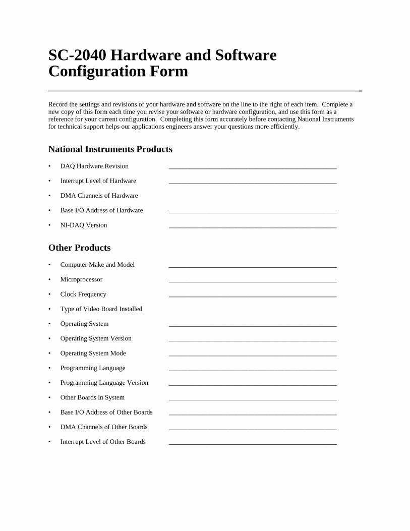
SC-2040 Hardware and SoftwareConfiguration Form Record the settings and revisions of your hardware and software on the line to the right of each item. Complete anew copy of this form each time you revise your software or hardware configuration, and use this form as areference for your current configuration. Completing this form accurately before contacting National Instrumentsfor technical support helps our applications engineers answer your questions more efficiently.
National Instruments Products
• DAQ Hardware Revision __________________________________________________
• Interrupt Level of Hardware __________________________________________________
• DMA Channels of Hardware
• Base I/O Address of Hardware __________________________________________________
• NI-DAQ Version __________________________________________________
Other Products
• Computer Make and Model __________________________________________________
• Microprocessor __________________________________________________
• Clock Frequency __________________________________________________
• Type of Video Board Installed
• Operating System __________________________________________________
• Operating System Version __________________________________________________
• Operating System Mode __________________________________________________
• Programming Language __________________________________________________
• Programming Language Version __________________________________________________
• Other Boards in System __________________________________________________
• Base I/O Address of Other Boards __________________________________________________
• DMA Channels of Other Boards __________________________________________________
• Interrupt Level of Other Boards __________________________________________________

Documentation Comment Form
National Instruments encourages you to comment on the documentation supplied with our products. Thisinformation helps us provide quality products to meet your needs.
Title: SC-2040 User Manual
Edition Date: September 1994
Part Number: 371191A-01
Please comment on the completeness, clarity, and organization of the manual.
If you find errors in the manual, please record the page numbers and describe the errors.
Thank you for your help.
Name
Title
Company
Address
Phone ( )
Mail to: Technical Publications Fax to: Technical PublicationsNational Instruments Corporation National Instruments Corporation6504 Bridge Point Parkway, MS 53-02 MS 53-02Austin, TX 78730-5039 (512) 794-5678
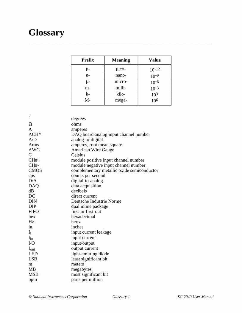
© National Instruments Corporation Glossary-1 SC-2040 User Manual
Glossary___________________________________________________
Prefix Meaning Value
p- pico- 10-12
n- nano- 10-9
µ- micro- 10-6
m- milli- 10-3
k- kilo- 103
M- mega- 106
˚ degreesΩ ohmsA amperesACH# DAQ board analog input channel numberA/D analog-to-digitalArms amperes, root mean squareAWG American Wire GaugeC CelsiusCH#+ module positive input channel numberCH#- module negative input channel numberCMOS complementary metallic oxide semiconductorcps counts per secondD/A digital-to-analogDAQ data acquisitiondB decibelsDC direct currentDIN Deutsche Industrie NormeDIP dual inline packageFIFO first-in-first-outhex hexadecimalHz hertzin. inchesII input current leakageIin input currentI/O input/outputIout output currentLED light-emitting diodeLSB least significant bitm metersMB megabytesMSB most significant bitppm parts per million
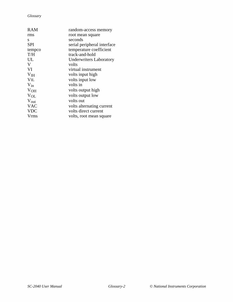
Glossary
SC-2040 User Manual Glossary-2 © National Instruments Corporation
RAM random-access memoryrms root mean squares secondsSPI serial peripheral interfacetempco temperature coefficientT/H track-and-holdUL Underwriters LaboratoryV voltsVI virtual instrumentVIH volts input highVIL volts input lowVin volts inVOH volts output highVOL volts output lowVout volts outVAC volts alternating currentVDC volts direct currentVrms volts, root mean square
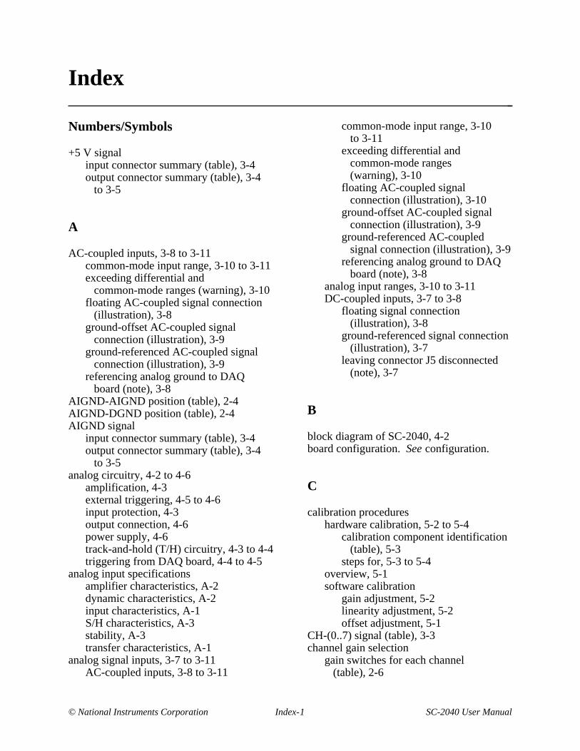
© National Instruments Corporation Index-1 SC-2040 User Manual
Index
Numbers/Symbols
+5 V signalinput connector summary (table), 3-4output connector summary (table), 3-4
to 3-5
A
AC-coupled inputs, 3-8 to 3-11common-mode input range, 3-10 to 3-11exceeding differential and
common-mode ranges (warning), 3-10floating AC-coupled signal connection
(illustration), 3-8ground-offset AC-coupled signal
connection (illustration), 3-9ground-referenced AC-coupled signal
connection (illustration), 3-9referencing analog ground to DAQ
board (note), 3-8AIGND-AIGND position (table), 2-4AIGND-DGND position (table), 2-4AIGND signal
input connector summary (table), 3-4output connector summary (table), 3-4
to 3-5analog circuitry, 4-2 to 4-6
amplification, 4-3external triggering, 4-5 to 4-6input protection, 4-3output connection, 4-6power supply, 4-6track-and-hold (T/H) circuitry, 4-3 to 4-4triggering from DAQ board, 4-4 to 4-5
analog input specificationsamplifier characteristics, A-2dynamic characteristics, A-2input characteristics, A-1S/H characteristics, A-3stability, A-3transfer characteristics, A-1
analog signal inputs, 3-7 to 3-11AC-coupled inputs, 3-8 to 3-11
common-mode input range, 3-10to 3-11
exceeding differential andcommon-mode ranges(warning), 3-10
floating AC-coupled signalconnection (illustration), 3-10
ground-offset AC-coupled signalconnection (illustration), 3-9
ground-referenced AC-coupledsignal connection (illustration), 3-9
referencing analog ground to DAQboard (note), 3-8
analog input ranges, 3-10 to 3-11DC-coupled inputs, 3-7 to 3-8
floating signal connection(illustration), 3-8
ground-referenced signal connection(illustration), 3-7
leaving connector J5 disconnected(note), 3-7
B
block diagram of SC-2040, 4-2board configuration. See configuration.
C
calibration procedureshardware calibration, 5-2 to 5-4
calibration component identification(table), 5-3
steps for, 5-3 to 5-4overview, 5-1software calibration
gain adjustment, 5-2linearity adjustment, 5-2offset adjustment, 5-1
CH-(0..7) signal (table), 3-3channel gain selection
gain switches for each channel(table), 2-6
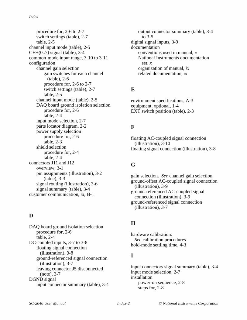
Index
SC-2040 User Manual Index-2 © National Instruments Corporation
procedure for, 2-6 to 2-7switch settings (table), 2-7table, 2-5
channel input mode (table), 2-5CH+(0..7) signal (table), 3-4common-mode input range, 3-10 to 3-11configuration
channel gain selectiongain switches for each channel
(table), 2-6procedure for, 2-6 to 2-7switch settings (table), 2-7table, 2-5
channel input mode (table), 2-5DAQ board ground isolation selection
procedure for, 2-6table, 2-4
input mode selection, 2-7parts locator diagram, 2-2power supply selection
procedure for, 2-6table, 2-3
shield selectionprocedure for, 2-4table, 2-4
connectors J11 and J12overview, 3-1pin assignments (illustration), 3-2
(table), 3-3signal routing (illustration), 3-6signal summary (table), 3-4
customer communication, xi, B-1
D
DAQ board ground isolation selectionprocedure for, 2-6table, 2-4
DC-coupled inputs, 3-7 to 3-8floating signal connection
(illustration), 3-8ground-referenced signal connection
(illustration), 3-7leaving connector J5 disconnected
(note), 3-7DGND signal
input connector summary (table), 3-4
output connector summary (table), 3-4to 3-5
digital signal inputs, 3-9documentation
conventions used in manual, xNational Instruments documentation
set, xorganization of manual, ixrelated documentation, xi
E
environment specifications, A-3equipment, optional, 1-4EXT switch position (table), 2-3
F
floating AC-coupled signal connection(illustration), 3-10
floating signal connection (illustration), 3-8
G
gain selection. See channel gain selection.ground-offset AC-coupled signal connection
(illustration), 3-9ground-referenced AC-coupled signal
connection (illustration), 3-9ground-referenced signal connection
(illustration), 3-7
H
hardware calibration.See calibration procedures.
hold-mode settling time, 4-3
I
input connectors signal summary (table), 3-4input mode selection, 2-7installation
power-on sequence, 2-8steps for, 2-8
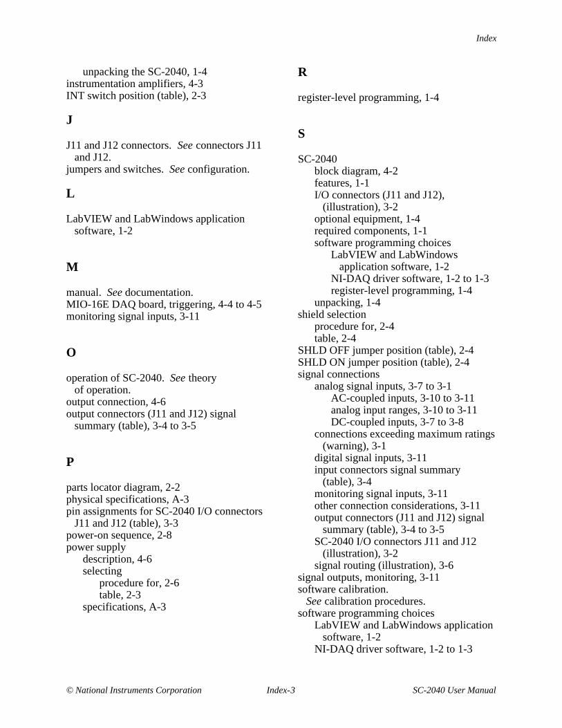
Index
© National Instruments Corporation Index-3 SC-2040 User Manual
unpacking the SC-2040, 1-4instrumentation amplifiers, 4-3INT switch position (table), 2-3
J
J11 and J12 connectors. See connectors J11and J12.
jumpers and switches. See configuration.
L
LabVIEW and LabWindows applicationsoftware, 1-2
M
manual. See documentation.MIO-16E DAQ board, triggering, 4-4 to 4-5monitoring signal inputs, 3-11
O
operation of SC-2040. See theoryof operation.
output connection, 4-6output connectors (J11 and J12) signal
summary (table), 3-4 to 3-5
P
parts locator diagram, 2-2physical specifications, A-3pin assignments for SC-2040 I/O connectors
J11 and J12 (table), 3-3power-on sequence, 2-8power supply
description, 4-6selecting
procedure for, 2-6table, 2-3
specifications, A-3
R
register-level programming, 1-4
S
SC-2040block diagram, 4-2features, 1-1I/O connectors (J11 and J12),
(illustration), 3-2optional equipment, 1-4required components, 1-1software programming choices
LabVIEW and LabWindowsapplication software, 1-2
NI-DAQ driver software, 1-2 to 1-3register-level programming, 1-4
unpacking, 1-4shield selection
procedure for, 2-4table, 2-4
SHLD OFF jumper position (table), 2-4SHLD ON jumper position (table), 2-4signal connections
analog signal inputs, 3-7 to 3-1AC-coupled inputs, 3-10 to 3-11analog input ranges, 3-10 to 3-11DC-coupled inputs, 3-7 to 3-8
connections exceeding maximum ratings(warning), 3-1
digital signal inputs, 3-11input connectors signal summary
(table), 3-4monitoring signal inputs, 3-11other connection considerations, 3-11output connectors (J11 and J12) signal
summary (table), 3-4 to 3-5SC-2040 I/O connectors J11 and J12
(illustration), 3-2signal routing (illustration), 3-6
signal outputs, monitoring, 3-11software calibration.
See calibration procedures.software programming choices
LabVIEW and LabWindows applicationsoftware, 1-2
NI-DAQ driver software, 1-2 to 1-3
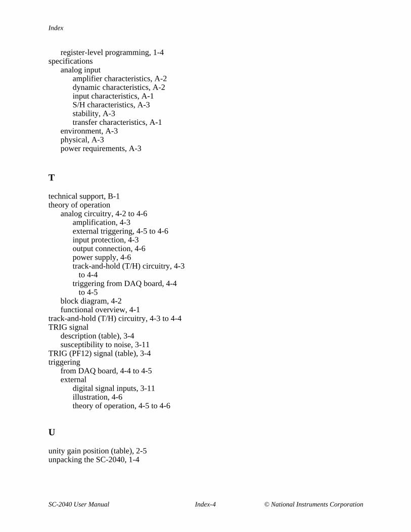
Index
SC-2040 User Manual Index-4 © National Instruments Corporation
register-level programming, 1-4specifications
analog inputamplifier characteristics, A-2dynamic characteristics, A-2input characteristics, A-1S/H characteristics, A-3stability, A-3transfer characteristics, A-1
environment, A-3physical, A-3power requirements, A-3
T
technical support, B-1theory of operation
analog circuitry, 4-2 to 4-6amplification, 4-3external triggering, 4-5 to 4-6input protection, 4-3output connection, 4-6power supply, 4-6track-and-hold (T/H) circuitry, 4-3
to 4-4triggering from DAQ board, 4-4
to 4-5block diagram, 4-2functional overview, 4-1
track-and-hold (T/H) circuitry, 4-3 to 4-4TRIG signal
description (table), 3-4susceptibility to noise, 3-11
TRIG (PF12) signal (table), 3-4triggering
from DAQ board, 4-4 to 4-5external
digital signal inputs, 3-11illustration, 4-6theory of operation, 4-5 to 4-6
U
unity gain position (table), 2-5unpacking the SC-2040, 1-4