Embed Size (px)
Citation preview

Vinayak Hegde, Nokia of America Corporation
LTE HANDOVER ENHANCEMENTS FOR HIGH SPEED CELLULAR RANGE TELEMETRY
Approved for public release; distribution is unlimited
412TW-PA-18041 Acknowledgment of Support: This project is managed by the Test Resource Management Center (TRMC) and funded through Spectrum
Access R&D Program via Picatinny Arsenal under Contract No. W15QKN-15-9-1004. The Executing Agent and Program Manager work out of
the AFTC
Disclaimer: Any opinions, findings and conclusions or recommendations expressed in this material are those of the author(s) and do not
necessarily reflect the views of the TRMC, the SAR&D Program and/or the Picatinny Arsenal.
Test Resource Management Center (TRMC)National Spectrum Consortium (NSC) / Spectrum Access R&D Program

2
• Provide test range coverage using a “cellular” paradigm (frequency re-use with inter-cell handover)
• Use of lower C-Band spectrum which is less congested
• Use of LTE’s spectrally efficient OFDM waveform capable of providing high throughput
• Seamless handover as multiple test articles move across the cells covering the test range
Cellular Range Telemetry
Technology focus
BS: Base Station. Site of an
eNodeB ground station
Ax – Bx –Cx : Sectors
Cellular Based AMT

3
Why is Handover needed?
• Handover in LTE refers to the procedure used by the LTE network to provide continuous and seamless data service as the UE moves through the different cells of the network. As the UE moves from the coverage of one cell to another cell, the handover procedure is initiated to maintain seamless mobility. The basic objectives of handover procedures are to maintain the connectivity and the data service as the UE moves in the coverage area of the network.
Aircraft Flying at Mach 2.5
Intra-Site Handover
Inter-Site Handover
Notional Flight Path
4
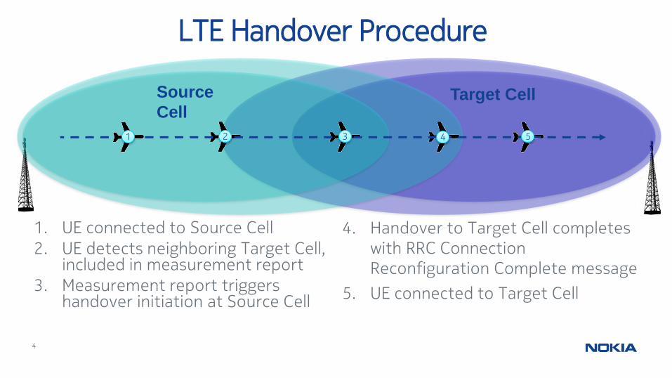
LTE Handover Procedure
2 3 4 51
Source
CellTarget Cell
4. Handover to Target Cell completes with RRC Connection Reconfiguration Complete message
5. UE connected to Target Cell
1. UE connected to Source Cell
2. UE detects neighboring Target Cell, included in measurement report
3. Measurement report triggers handover initiation at Source Cell
5
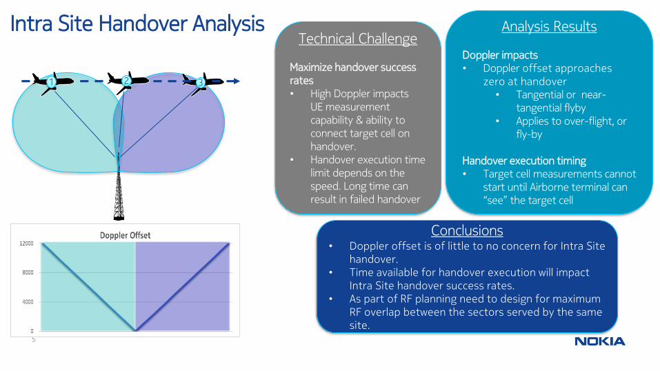
Intra Site Handover Analysis
321
Analysis Results
Doppler impacts • Doppler offset approaches
zero at handover• Tangential or near-
tangential flyby• Applies to over-flight, or
fly-by
Handover execution timing• Target cell measurements cannot
start until Airborne terminal can “see” the target cell
Conclusions• Doppler offset is of little to no concern for Intra Site
handover.• Time available for handover execution will impact
Intra Site handover success rates.• As part of RF planning need to design for maximum
RF overlap between the sectors served by the same site.
Technical Challenge
Maximize handover success rates• High Doppler impacts
UE measurement capability & ability to connect target cell on handover.
• Handover execution time limit depends on the speed. Long time can result in failed handover

6
Inter Site Handover Analysis
321
Technical Challenge
Maximize handover success rates• High Doppler impacts
UE measurement capability & ability to connect target cell on handover.
• Handover execution time limit depends on the speed. Long time can result in failed handover
Analysis Results
Doppler impacts • Maximized, due to extreme
Doppler offset from each site.• Transition from high negative
Doppler to high positive offset during handover.
Handover execution timing• Simpler timeline in this
scenario due to significant Site-to-Site RF coverage overlap
Conclusions• Doppler impact is the highest for Site-to-Site
handover.• For lower C-Band operation and speeds
approaching MACH 2, the Doppler estimation component needs to handle Doppler offsets as high as 12KHz for the serving and neighbor cells.

7
Doppler Equation
Analysis of Doppler Shift vs Speed in Lower C-Band
A Monte Carlo Characterization
Analysis ResultsMonte Carlo Doppler characterization with airborne test article having a velocity ceiling of MACH 2.5 and altitude between 150 m and 15 km• 90%-ile Doppler shift is 8 kHz.
Conclusions• 90%-ile Doppler shift is within the
LTE subcarrier spacing of 15 kHz. • The actual Doppler shifts at 4.7 GHz
is less stringent than the calculated Doppler shift.

8
Maximum Doppler Rate of Change Analysis
e.g, F-16 Specific Energy Curves
Technical Challenge
Maximize Cell Attach Success rates• Limits on rate of change
of Doppler influence the capability of the Airborne Terminal to attach to the network and maintain connection.
Analysis Results• Maximum rate of change of Doppler
happens when Aircraft executes a tight turn, heading directly toward site and reverses direction within the coverage of a sector
• Evaluated maximum Doppler rate of change at airspeed of highest turn rate
• Mach 0.75, 19 degrees/sec = 803 Hz/s (F16)
• Mach 0.75, 6 degrees/sec = 254 Hz/s (Cessna Citation)
Conclusions• Rate of change of Doppler are in the limits that can
be handled by the Airborne Terminal using sufficient doppler measurement updates.
• Need to design the Doppler estimation component with sufficient margins to handle such rate of changes of Doppler.
9
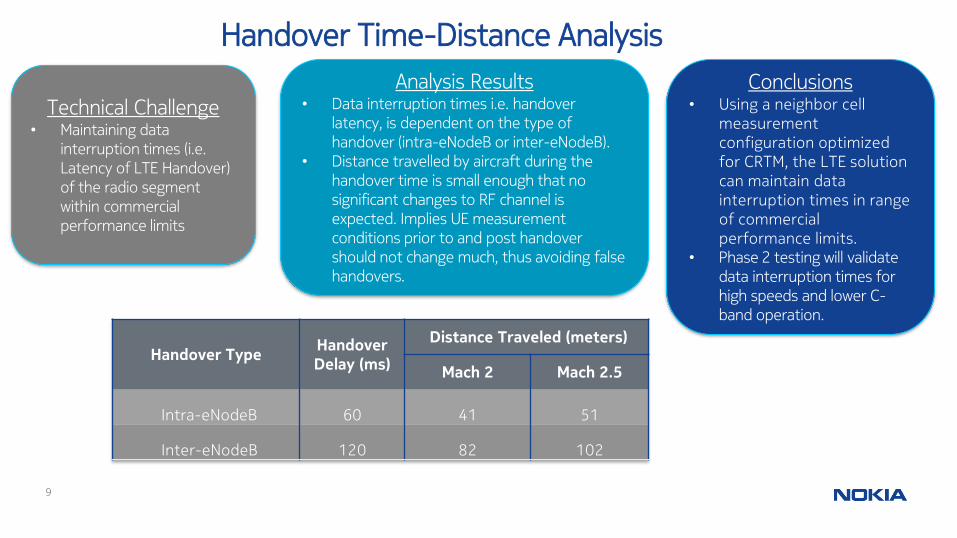
Handover Time-Distance Analysis
Handover TypeHandover Delay (ms)
Distance Traveled (meters)
Mach 2 Mach 2.5
Intra-eNodeB 60 41 51
Inter-eNodeB 120 82 102
Technical Challenge• Maintaining data
interruption times (i.e. Latency of LTE Handover) of the radio segment within commercial performance limits
Analysis Results• Data interruption times i.e. handover
latency, is dependent on the type of handover (intra-eNodeB or inter-eNodeB).
• Distance travelled by aircraft during the handover time is small enough that no significant changes to RF channel is expected. Implies UE measurement conditions prior to and post handover should not change much, thus avoiding false handovers.
Conclusions• Using a neighbor cell
measurement configuration optimized for CRTM, the LTE solution can maintain data interruption times in range of commercial performance limits.
• Phase 2 testing will validate data interruption times for high speeds and lower C-band operation.

10
Handover Test Results – Handover Success Rates
Handover Test Setup• UE operating in S-Band
• Doppler shifts under 2 KHz (i.e. up to MACH 1 speeds)
OBSERVATIONS
• Successfully able to extend 3GPP Doppler compensation limits and UE Measurement Capabilities with Air 2 Ground Doppler compensation design.
• Latest lab test results show the Airborne Transceiver’s cell tracker successfully tracking and compensating for Doppler shifts up to 6.5KHz
• Gives confidence that the Doppler compensation approach can work for MACH2 speeds in lower C-Band.
• Testing for > MACH 1 speed and lower C-Band operation are in progress

11
Handover Test Results – Handover Latency
Testcase Inra eNodeB Handover RSRP -115dBm
Air to Ground Data
Interruption Time ms
Ground to Air Data
Interruption Time ms
Air to Ground Data
Interruption Time ms
Ground to Air Data
Interruption Time ms
Cell 0 to Cell 1 (1) 63 82 Cell 1 to Cell 0 (1) 52 69
Cell 0 to Cell 1 (2) 62 86 Cell 1 to Cell 0 (2) 53 70
Cell 0 to Cell 1 (3) 53 70 Cell 1 to Cell 0 (3) 56 60
Average 59.33 79.33 Average 53.67 66.33
Testcase Inter eNodeB Handover RSRP -115dBm
Air to Ground Data
Interruption Time ms
Ground to Air Data
Interruption Time ms
Air to Ground Data
Interruption Time ms
Ground to Air Data
Interruption Time ms
eNodeB 0 to eNodeB 1 (1) 49 60 eNodeB 1 to eNodeB 0 (1) 48 65
eNodeB 0 to eNodeB 1 (2) 44 57 eNodeB 1 to eNodeB 0 (2) 50 70
eNodeB 0 to eNodeB 1 (3) 46 63 eNodeB 1 to eNodeB 0 (3) 57 63
Average 46.33 60 Average 51.67 66
No Backhaul Delay No Backhaul Delay
No Backhaul Delay
UDP Handover Cell0 -> Cell1 UDP Handover Cell1 -> Cell0
No Backhaul Delay
UDP Handover eNodeB0 -> eNodeB1 UDP Handover eNodeB1 -> eNodeB0
Handover Test Setup• UE operating in S-Band
• Static Channel
• Doppler shifts under 2 KHz (i.e. up to MACH 1 speeds)
OBSERVATIONS• Data service interruption times within expected range
(60ms) • Our inference from testing is, for > MACH 1 speed and
C-Band the impact to latency time should be marginal.• Testing in next phase will validate > MACH 1 latency

12
Conclusion
• This paper shows the challenges for extending 3GPP LTE seamless handover to work at the high speeds for Aeronautical Mobile telemetry.
• Nokia is building upon its commercial Air to Ground LTE solution to address these challenges for Cellular Range Telemetry.
• The studies and simulations performed by Nokia using its S-Band Air to Ground LTE equipment indicate that Doppler and handover timing constraints can be addressed with • modification to the Airborne Terminal’s Doppler estimation and
compensation algorithms• Optimization of the handover measurement configuration