Embed Size (px)
Citation preview
National Transportation Safety Board Office of Aviation Safety
Washington, D.C. 20594-2000 May 29, 2014
GEAR BOX EXAM FACTUAL REPORT ERA14LA130
A. Accident
Location: Apopka, Florida Date: February 23, 2014 Time: 1335 EST Vehicle: Victor M Cordero, RV-9A, S/N 90319, N19VC, Experimental Amateur Built Engine: Eggenfellner Subaru EJ25 Automobile Engine Conversion
B. Investigators
Stephen Stein Air Safety Investigator (IIC) National Transportation Safety Board 45065 Riverside Parkway Ashburn, VA 20147 John Clark Senior Technical Advisor National Transportation Safety Board 45065 Riverside Parkway Ashburn, VA 20147
C. Summary
On February 23, 2014, about 1335 Eastern Standard Time, an experimental amateur built RV-9A airplane, N19VC, operated by a private individual, was substantially damaged during an emergency landing in Apopka, Florida. The instrument rated private pilot received minor injuries and the passenger sustained serious injuries. Visual meteorological conditions prevailed for the

personal flight conducted under Title 14 Code of Federal Regulations Part 91. The pilot cancelled his instrument flight rules (IFR) flight plan and was operating under visual flight rules. The flight originated from Marsh Harbour International Airport (MYAM), Marsh Harbour, Bahamas at 1130 and was destined for Orlando Sanford International Airport (SFB), Orlando, Florida.
According to the pilot's written statement he cancelled his IFR clearance at 3,000 feet and
was cleared to maintain his "present heading" for runway 9L. Two minutes later, about 1330, the propeller suddenly stopped rotating, but the engine appeared to function normally. There were no annunciations or warnings on the engine monitoring unit. The pilot executed an emergency landing near Apopka Airport (X04). During the landing roll, the airplane nosed over and came to rest in an inverted attitude.
D. Details of Investigation
The pilot reported that the propeller stopped while in flight. He also reported that the engine continued to run. The engine, propeller speed reduction unit (PSRU), and power train hardware were examined at H3Aero Concepts in Groveland, Florida on May 6, 2014. Examination showed that the splined components were free of lubrication and severely worn. At the engine end of the spline components, the spline shaft teeth and the walls of the drive disk adapter grooves were worn to the point that the spline shaft would rotate freely within the adapter. The remaining material bent over at the tips of the thinned spline teeth and thinned walls. Further examination showed similar, but less severe wear at the PSRU end of the spline components. The PSRU input spline grooves were worn such that the widths of the walls between grooves were 40% less than the original width. The spline teeth on the PSRU-end of the spline shaft were worn such that the thicknesses of the teeth were more than 25% less than the original thickness. The spline shaft would wobble when inserted into the PSRU input spline. There was free play when the spline shaft was rotated while inserted into the input spline.
1.0 Airframe History
The experimental amateur built airplane was built from a series of kits provided by Vans Aircraft, Inc.1 and Eggenfellner Aircraft, LLC2. The airplane was registered as Experimental Amateur Built; N19VC; the airworthiness certificate was issued on July 18, 2011. The engine information system (EIS) showed that the total time for the airframe and engine was 324.5 hours.
2.0 Engine History
The experimental Eggenfellner Subaru H4 engine installation was designed and sold by Eggenfellner Aircraft. The design is based on an EJ-25, 2.5L Subaru water cooled 4-cylinder engine and is rated at 160 HP and 5400 rpm. The electronic ignition system was adapted by Eggenfellner Aircraft, Inc.
1 Van’s Aircraft, Inc; Aurora, OR 2 Eggenfellner Aircraft, LLC; Edgewater, FL; Eggenfellner Aircraft is no longer in business.
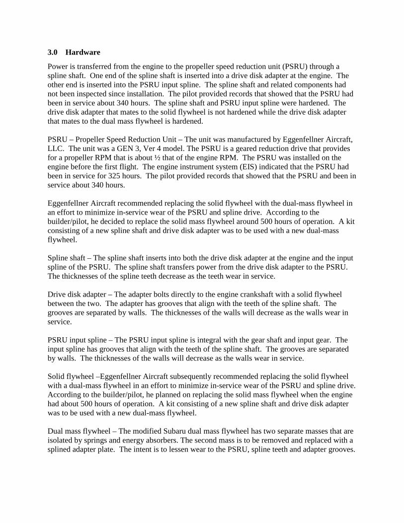
3.0 Hardware
Power is transferred from the engine to the propeller speed reduction unit (PSRU) through a spline shaft. One end of the spline shaft is inserted into a drive disk adapter at the engine. The other end is inserted into the PSRU input spline. The spline shaft and related components had not been inspected since installation. The pilot provided records that showed that the PSRU had been in service about 340 hours. The spline shaft and PSRU input spline were hardened. The drive disk adapter that mates to the solid flywheel is not hardened while the drive disk adapter that mates to the dual mass flywheel is hardened. PSRU – Propeller Speed Reduction Unit – The unit was manufactured by Eggenfellner Aircraft, LLC. The unit was a GEN 3, Ver 4 model. The PSRU is a geared reduction drive that provides for a propeller RPM that is about ½ that of the engine RPM. The PSRU was installed on the engine before the first flight. The engine instrument system (EIS) indicated that the PSRU had been in service for 325 hours. The pilot provided records that showed that the PSRU and been in service about 340 hours. Eggenfellner Aircraft recommended replacing the solid flywheel with the dual-mass flywheel in an effort to minimize in-service wear of the PSRU and spline drive. According to the builder/pilot, he decided to replace the solid mass flywheel around 500 hours of operation. A kit consisting of a new spline shaft and drive disk adapter was to be used with a new dual-mass flywheel. Spline shaft – The spline shaft inserts into both the drive disk adapter at the engine and the input spline of the PSRU. The spline shaft transfers power from the drive disk adapter to the PSRU. The thicknesses of the spline teeth decrease as the teeth wear in service. Drive disk adapter – The adapter bolts directly to the engine crankshaft with a solid flywheel between the two. The adapter has grooves that align with the teeth of the spline shaft. The grooves are separated by walls. The thicknesses of the walls will decrease as the walls wear in service. PSRU input spline – The PSRU input spline is integral with the gear shaft and input gear. The input spline has grooves that align with the teeth of the spline shaft. The grooves are separated by walls. The thicknesses of the walls will decrease as the walls wear in service. Solid flywheel –Eggenfellner Aircraft subsequently recommended replacing the solid flywheel with a dual-mass flywheel in an effort to minimize in-service wear of the PSRU and spline drive. According to the builder/pilot, he planned on replacing the solid mass flywheel when the engine had about 500 hours of operation. A kit consisting of a new spline shaft and drive disk adapter was to be used with a new dual-mass flywheel. Dual mass flywheel – The modified Subaru dual mass flywheel has two separate masses that are isolated by springs and energy absorbers. The second mass is to be removed and replaced with a splined adapter plate. The intent is to lessen wear to the PSRU, spline teeth and adapter grooves.

At the examination, the Eggenfellner Aircraft, LLC representative stated that all of the splines would fail if the dual-mass flywheel was not incorporated into the installation.
4.0 Other Findings
The wear surfaces of the spline components were free of a recommended antiseize compound.3 Upon disassembly of the spline shaft from the PRSU, approximately one teaspoon of red dust (consistent with ferrous fretting-wear debris) was observed in the cavity of the PSRU input spline. Examination of the spline shaft and drive disk adapter using a 5X to 50X stereo zoom microscope revealed the flanks of the spline shaft teeth that mate with the drive disk adapter were worn by about 75%, with the tips of the teeth forming sharp cusps that had been bent over consistent with rotation of the spline shaft within the drive disk adapter. Wear surface features on the spline shaft teeth were consistent with fretting wear that had progressed to adhesive wear. The grooves in the drive disk adapter were worn such that the wall between grooves was thinned by more than 75%, forming sharp cusps that had been bent over consistent with rotation of the spline shaft within the drive disk adapter. Wear surface features on the groove surfaces of drive disk adapter were consistent with fretting wear that had progressed to adhesive wear. Examination of the spline shaft teeth that mate with the PSRU input spline using a 5X to 50X stereo zoom microscope revealed the flanks of the spline shaft teeth were worn by more than 25%. Wear surface features on the spline shaft teeth were consistent with fretting wear that had progressed to adhesive wear. A deposit on the drive disk adapter was examined using a scanning electron microscope with energy dispersive spectrometer. The composition and morphology of the deposit was consistent with a copper/zinc-based anti-seize compound. A rolling element ball bearing pressed onto the drive disk adapter side of the spline shaft had a separated shield and no grease was present. The ball retainer was fractured in two locations and a ball was missing. The inner and outer bearing race surfaces and the outside surfaces of the balls and ball retainer were dark blue-black in color, consist with elevated temperature exposure.
3 Antiseize compounds help protect metal parts from galling and fretting caused by hight temperatures, heavy loads and vibration. Eggenfellner Aircraft had recommended using a copper based antiseize compound in this application.

5.0 Examination
Photo 1 – Overall view of Gen 3 Version 4 PSRU.
Photo 2 – Propeller hub.

Photo 3 – The spline shaft is inserted into the drive disk adapter. A puller was used to remove the spline shaft and bearing. Red dust coated the spline shaft. Much of the dust could be picked up with a magnet. Examination indicated that the dust was the consistent with fretting corrosion.
Photo 4 – There is more than 25% wear of the teeth on the PSRU end of the spline (left arrow). There is more than 75% wear of the walls on the drive disk adapter (right arrow).

Photo 5 –There was direct mechanical damage and more than 75% wear of the spline teeth on the engine end of the spline shaft. The tips of the spline teeth were rolled over. The cuts on the PSRU-end of the drive shaft were made to facilitate the use of a puller. There is more than 25% wear of the spline teeth on the PSRU end of the spline shaft.
Photo 6 –There was over 75% wear of the walls on the drive disk adapter. The tips of the walls were bent over.
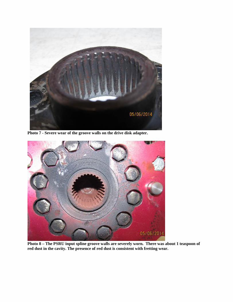
Photo 7 - Severe wear of the groove walls on the drive disk adapter.
Photo 8 – The PSRU input spline groove walls are severely worn. There was about 1 teaspoon of red dust in the cavity. The presence of red dust is consistent with fretting wear.

Photo 9 - The PSRU input spline is worn to the point that the walls are pointed.
Photo 10 – The PSRU input spline with dust removed.

Photo 11 – The upper arrow generally points to the many worn spline walls. The lower arrow points to the wear in the groove walls. The wear at the groove was more than 25%. Each spline had similar wear.
Photo 12 – Red dust collected with a magnet.

Photo 13 – PSRU opened. The oil in the case appeared clear. There was no sediment inside the case.
Photo 14 – Arrow shows polished area of wear.

Photo 15 - Arrow shows polished area of wear.
Photo 16 - Arrow shows polished area of wear.

Photo 17 – The spline shaft is pushed to the left, closing the gap between the PSRUinput spline and the spline shaft.
Photo 18- The spline shaft is pushed to the right, opening the gap between the PSRU input spline and the spline shaft.

Photo 19 – The left arrows point to the closed gap, the right arrows point to the open gap. Stephen Stein
John Clark