Embed Size (px)
Citation preview

DOCKET NO. SA- 516
EXHIBIT NO. 7A
NATIONAL TRANSPORTATION SAFETY BOARDWASHINGTON, D.C
STRUCTURES GROUP CHAIRMAN’S FACTUALREPORT OF INVESTIGATION
NATIONAL TRANSPORTATION SAFETY BOARDOffice of Aviation SafetyWashington, DC 20594
February 20, 1997
STRUCTURES GROUP CHAIRMAN'S FACTUAL REPORT
DCA-96-MA-070
A. ACCIDENT
Location : East Moriches, New YorkDate : July 17, 1996Time : 2031 Eastern Daylight TimeAircraft : Boeing 747-131, N93119
Operated as Trans World Airlines (TWA) Flight 800
B. STRUCTURES GROUP
Chairman
Member
Member
Member
Member
Member
Deepak JoshiNational Transportation Safety BoardWashington, DC
Jim PowersBoeing Commercial Airplane GroupSeattle, WA
Steve ChisholmBoeing Commercial Airplane GroupSeattle, WA
Roy HurlbutBoeing Commercial Airplane GroupSeattle, WA
Rob HarrowerBoeing Commercial Airplane Group Seattle, WA
Bob Whittington
Boeing Commercial Airplane GroupSeattle, WA
1

Member
Member
Bruce HockingBoeing Commercial Airplane GroupSeattle, WA
Barry SmithBoeing Commercial Airplane GroupSeattle, WA
Member Henry MisselBoeing Commercial Airplane GroupSeattle, WA
Member Warren SteyaertBoeing Commercial Airplane GroupSeattle, WA
Member Arnie ReimerBoeing Commercial Airplane GroupSeatile, WA
Member Kelvin DeanBoeing’ Commercial Airplane GroupSeattle, WA
Member
Member
Member
Member
Member
Dave OrthBoeing Commercial Airplane GroupSeattle, WA
Lewis ThomsonBoeing Commercial Airplane GroupSeattle, WA
Steve GreenAir Line Pilots Association (ALPA)Herndon, VA
Ray StettnerAir Line Pilots Association (ALPA)Herndon, VA
Vinnie CoccaAir Line Pilots Association (ALPA)Herndon, VA
2

Member Dennis SantiagoInternational Association of Machinists (IAM)JFK Intl Airport, NY
Member Charles HaleInternational Association of Machinists (IAM)JFK Intl Airport, NY
Member Ron GiochettiInternational Association of Machinists (IAM)JFK Intl Airport, NY
Member
Member
Member
Member
George DoddInternational Association of Machinists (IAM)JFK Intl Airport, NY
Dan RephloTrans World Airlines (TWA)Kansas City, MO
Terry McKinneyTrans World Airlines (TWA)Kansas City, MO
Neil ScovilleTrans World Airlines (TWA)Kansas City, MO
Member Gean LivingstonTrans World Airlines (TWA)Kansas City, MO
Member Morris PocchiariTrans World Airlines (TWA)Kansas City, MO
Member Tom TodinoFederal Aviation Administration (FAA)Garden City, NY
Member Steve KlepackFederal Aviation Administration (FAA)
3

Garden City, NY
C. SUMMARY
On July 17, 1996, at 2031 EDT, a Boeing 747-131, N93119 operated as TransWorld Airlines Flight 800 from John F. Kennedy Airport, New York, to CharlesDeGaulle Airport, Paris, France, impacted into the Atlantic Ocean at approximately40’39’52” N, 72°37’46” W near East Moriches, New York. The crew of 18 and the 212passengers received fatal injuries and the airplane was destroyed. The scheduled aircarrier flight was operated under Title 14, Code of Federal Regulations (CFR) Part 121.Visual meteorological conditions prevailed and an instrument flight rules (IFR) flightplan was filed.
D. DETAILS OF THE INVESTIGATION
1.0 Wreckage Recovery and Impact Information
The wreckage recovery began immediately after the accident with several vesselspicking up pieces that were floating on the surface of the water. Subsequently, thewreckage that sank was remotely surveyed using a variety of techniques, principally sidescan sonar and laser line scanning. The aircraft was flying on a true course ofapproximately 075°. The wreckage was distributed along a true course of approximately060 in three major dispersals, all of which lay predominantly to the south of the aircraft’sground track. The wreckage was generally distributed as far west as 72°40’ 48”W, as fareast as 72°35’ 38”W, as far north 40°40’ 12”N, and as far south as 40° 37’ 42”N.
The three major dispersals of wreckage resulted in three specific debris fieldsbeing identified. The westernmost was originally known as area 3, because it was the lastof the three to be located. Subsequently, this became the red zone. Its comers were:
40° 39’ 21.72”N, 072° 40’ 43.26”W40° 37’ 16.68”N, 072° 40’ 47.59”W40° 37’ 16.58”N, 072° 37’ 20.03”W40° 38’ 57.02”N, 072° 37’ 16.47”W
. 40° 38’ 57.73”N 072° 37’ 51.32”W40° 39’ 18.20”N 072° 37’ 50.60”W
The corresponding distance dimensions of this area are approximately 2.65nautical miles along the east west axis by 2.1 nautical miles along the north south axis.However the northeast comer of the rectangle overlaps Area 1 by approximately .375 nmsquare and is part of Area 1 (Green). (See Appendix A, Section A 1 for detail of wreckagerecovery areas and wreckage distribution).
4
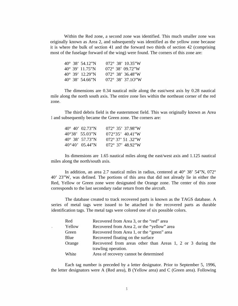
Within the Red zone, a second zone was identified. This much smaller zone wasoriginally known as Area 2, and subsequently was identified as the yellow zone becauseit is where the bulk of section 41 and the forward two thirds of section 42 (comprisingmost of the fuselage forward of the wing) were found. The corners of this zone are:
40° 38’ 54.12”N 072° 38’ 10.35”W40° 39’ 11.75”N 072° 38’ 09.72”W40° 39’ 12.29”N 072° 38’ 36.48”W40° 38’ 54.66”N 072° 38’ 37.1O”W
The dimensions are 0.34 nautical mile along the east/west axis by 0.28 nauticalmile along the north south axis. The entire zone lies within the northeast corner of the redzone.
The third debris field is the easternmost field. This was originally known as Area1 and subsequently became the Green zone. The corners are:
40° 40’ 02.73”N40°38’ 55.03”N40° 38’ 57.73”N40°40’ 05.44”N
Its dimensions are
072° 35’ 37.98”W072°35’ 40.41”W072° 37’ 51 .32”W072° 37’ 48.92”W
1.65 nautical miles along the east/west axis and 1.125 nauticalmiles along the north/south axis.
In addition, an area 2.7 nautical miles in radius, centered at 40° 38’ 54”N, 072°40’ 23”W, was defined. The portions of this area that did not already lie in either theRed, Yellow or Green zone were designated the Orange zone. The center of this zonecorresponds to the last secondary radar return from the aircraft.
The database created to track recovered parts is known as the TAGS database. Aseries of metal tags were issued to be attached to the recovered parts as durableidentification tags. The metal tags were colored one of six possible colors.
Red Recovered from Area 3, or the “red” area. Yellow Recovered from Area 2, or the “yellow” area
Green Recovered from Area 1, or the “green” areaBlue Recovered floating on the surfaceOrange Recovered from areas other than Areas 1, 2 or 3 during the
trawling operation.White Area of recovery cannot be determined
Each tag number is preceded by a letter designator. Prior to September 5, 1996,the letter designators were A (Red area), B (Yellow area) and C (Green area). Following
5

the hurricane which passed the area, it was considered prudent to change these letterprefixes, since it was considered that some wreckage may have shifted position due to thehurricane. Thus, after September 4, 1996, the following letters were used: X (Red area),Y (Yellow area) and Z (green area).
The letter D designates a piece that could not be associated with a specificwreckage field (White tag). The letter E designates a floating piece (Blue tag).
After the recovery ships concluded diving operations, a trawling program wasexecuted, using scallop boats with bottom dragging equipment to dredge the sea floor forparts. Any part recovered in this effort was given a colored tag appropriate to the area inwhich it was recovered; however, all pieces recovered in this effort were designated withunique letter prefixes. The letters T or M indicate a part recovered during the trawlingprior to January 1, 1997. The letter N and P indicates a part recovered during the trawlingafter December 31, 1996.
Following the letter designator, a number between 1 and 9999 was applied. Thesenumber series reflect the following information:
1-1999 Issued on the recovery ships prior to the hurricane
2000-2999 Issued at the Calverton hangar prior to the trawlingoperation. Exception: Z2551 -Z2650. These 100 tags wereissued on the warping tug.
3000-3999
4000-4999
5000-5999
6000-6999
.7000-7999
Issued on the recovery ships following the hurricane ofSeptember 4, 1996.
Issued at the Calverton hangar to wreckage recoveredduring the trawling operation.
Issued by SUPSALV personnel at Moriches
Issued on the trawlers working Area 1 (Green)
Issued on the trawlers working Area 3 (Red)Note: During the trawling operation, the Area 2 (Yellow)was not considered distinct from Area 3 (Red).
Note: Tag numbers T7064-T7084 were issued onboard theTradition while she was operating in Area 1 (Green).However, the tags were colored red in error. For accuracy,refer FBI lot #.
6

8000-8999
9000-9999
Issued on the trawlers working the eastern half of theOrange zone, and the area of the Orange zone that lies bothwithin and north of the AT&T cable safety zone.
Issued by the trawlers working the western half of theOrange zone.
Due to the enormous number of pieces recovered, not all parts were tagged. Largeparts were tagged consistently, as were smaller parts that were identifiable and consideredsignificant. However, a considerable volume of unidentifiable material was not tagged.
The FBI Evidence Response Team executed an evidence identification program,which placed a recovery date and recovery shipment (“lot”) number on each piece thatentered the hangar at Calverton, Long Island, New York. This program marked everypiece that was recovered. Often, the lot number can be traced to a single debris field.Occasionally, lots were mixed (red and/or green and/or yellow), thus making itimpossible to associate a specific debris field with a particular lot number.
A detail description of wreckage recovery operation and wreckage distribution isdocumented in Data Study Report and is prepared by the Data Management Team. Thisteam was responsible for proper placement of tags on recovered wreckage.
The wreckage was laid out on the hangar floor with a lengthwise gridcorresponding to the manufacturer’s longitudinal fuselage station designation system.Other areas of the hangar floor were laid out with the appropriate grids for placing partssuch as wing structure, wing center section with associated structure, and body fairings.Parts that were identified were placed in the appropriate position on the floor. Parts thatcould not be associated with a specific airplane position, but could be classified by typeof structure, were placed in one of several piles. Each of these piles was unique to aparticular type of structure and to a specific debris field. Parts that could not be associatedwith a type of structure, but could be associated with a debris field, were placed in amiscellaneous pile that was associated with the specific debris field.
Parts that were associated with the powerplants were transported to the hangarthat housed the powerplants for documentation by the PowerPlant Group. Likewise, partsthat were associated with the cabin interior were transported to another hangar where thecabin interior was documented and mocked up.
Major structures, substructures and significant components were documented. Thedocumentation was subdivided into 12 subgroups. These are: left fuselage, right fuselage,left wing, right wing, horizontal stabilizer, left elevator, right elevator, vertical stabilizer,rudder, wing center section, floor beams and landing gears. Each structure, prior todocumentation, was assigned a documentation number. The following nomenclature was
7

established for the documentation numbers:
LF-XXRF-xxLW-XXRW-XXH-XXLE-XXRE-XXV-XXR-XXCW-lxxCW-2XXCW-3XXCW-4XXCW-5XXCW-6XXCW-7XXCW-8XXCW-9XXCW-l0XXCW-11XXFBM-XXLG-XX
Left fuselageRight fuselageLeft main wingRight main wingHorizontal stabilizer (both sides)Left elevatorRight elevatorVertical stabilizerRudderWing Center Section upper skinWing Center Section lower skinWing Center Section right side-of-body ribWing Center Section left side-of-body ribWing Center Section front sparWing Center Section spanwise beam no. 3Wing Center Section spanwise beam no. 2Wing Center Section mid sparWing Center Section spanwise beam no. 1Wing Center Section rear sparWing Center Section butt line zero ribFloor beamLanding gear
The Structures Group documented the airplane structural pieces individually andcatalogued them in the Structures Group Factual Note Books. These books are comprisedof textual documentation, drawings and photographs organized by part documentationnumber. For example, the piece of wing center section structure upper skin designatedCW-101 has its textual documentation, sketches and photographs all located under thedivider labeled “CW- 101” in Book 1 of the Wing Center Section Structure. This divideris followed by the divider labeled “C W- 102” with its documentation, and so forth. Thebooks are comprised of the left fuselage, right fuselage, left wing, right wing, wing centersection structure, empennage, landing gear and engine pylons.
From this basic documentation, a Factual Summary Report was drafted for eachof the basic structures (fuselage, wings, empennage, wing center section, landing gears,engine struts). These reports comprise general descriptions of the significant featuresfound in each of these basic structures. More detail will be found in the Structures GroupFactual Note Books as described above.
The documentation for each individual piece, as well as each of the factualsummaries, were reviewed and accepted by the accredited representatives of each party tothe investigation.
8

This report and the factual summary reports include references to fire damage.The detailed description of all fire-related damage is included in the Fire and ExplosionsGroup Chairman’s Factual Report. Documentation of fire damage in the Structures GroupFactual Summaries refers to any evidence of fire-related damage, including thermaldiscoloration and the presence of soot as well as thermal damage to metal structure.
This report also includes detail sketches of structure and wreckagerecovery/distribution plots which is cataloged in Appendix A of this report. Appendix Ahas several sections, as indicated below:
Section Detail of Sketches
Al Wreckage Recovery and Wreckage DistributionA2 FuselageA3 WingA4 Center Wing Section (Also called as Wing Center Section)A5 EmpennageA6 Landing Gear and Landing Gear AssembliesA7 Engine Struts (Also called as Engine Pylons)
The Structures Group was also responsible for the documentation of fractures onimportant parts of the airplane wreckage. This documentation was done with the help of aMetallurgical Group and is cataloged in a separate book titled “Metallurgical FactualNotes”. A Sequencing Group was formed to document the aircraft breakup sequence.This documentation is titled Metallurgy/Structures Sequencing Group Notes. In additionto the above mentioned reports, there are various Metallurgical Group laboratory reportswhich were generated by the Metallurgical Group to document structure.
2.0 Fuselage
The fuselage of the airplane was severely fragmented and recoveredpredominantly from the three debris fields. (Some parts were recovered outside theseestablished debris fields during the trawling operation.) The Red debris field containedfuselage pieces from an area just forward of the center wing tank. Generally, these pieceswere from the circumference of the fuselage between fuselage station (STA) 840 and1000; all of the pieces in this area of the fuselage have not been accounted for. TheYellow debris field contained fuselage sections generally forward of STA 840. The Greendebris field contained fuselage sections generally aft of STA 1000. Some of the fuselagepieces from each of the above areas have not been identified.
Following are the acronyms used in this report:STA Body StationCWS Center Wing Section
9

s- StringerKBB Keel Beam BoxLBL/RBL Left/Right Buttock Line
2.1 Forward Fuselage
2.1.1 Section 41 and Forward End of Section 42
The forward section of the fuselage from STA 90 to approximately STA 840,comprising Section 41 and part of Section 42, was found in the Yellow debris field. Thefuselage skin and supporting structure extending below the right side passenger windowsat stringer 22R (S-22R) and the left side cargo floor (S-37L) broke into small sections andsuffered severe damage from inboard-acting compression/crushing forces. (See AppendixA Section A2 for detail sketches).
The fuselage section above S-22R and S-37L, including the crown, broke intolarger sections. The upper crown stringers (lR, O, lL, 2L, and 2AL) near STA 840 exhibitevidence of pure tension fracture. There was no evidence of pre-existing corrosion orcracking found on this section of the fuselage. There was no evidence of foreign objectimpact to the cockpit windows.
There was no evidence of in-flight or post-crash fire damage to pieces of thissection of the fuselage structure. There are numerous locations of dark/blackeneddiscoloration near the electrical standoffs and ground terminals (LF 1 lB and RF4).
2.1.2 Aft Portion of Section 42
The section of fuselage from approximately STA 840 to STA 1000, comprisingthe aft portion of Section 42, broke into several large pieces. Most of these pieces werefound in the Red debris field. A section of the fuselage skin aft of the R2 door (RF 1 ), justbelow the window belt, and above the cargo floor exhibiteda “peeling” deformation. Theaft, upper corner of the skin is curled outboard, down, and forward (with respect to thefuselage axis system), and then continues its curl wrapping around into itself. There issimilar peeling darnage to the corresponding region of skin on the left side of the fuselage(LF5), such that a nearly symmetrical condition has resulted..
Between STA 860 and 960, the main deck window belts and the fuselage skinabove the window belts on both sides (S-6 to S-23) exhibited longitudinal compressionbuckling deformation (LF12A, LF12B, LF38, LF59, LF74, LF85, RF20, RF21, andRF35). This condition is most severe immediately above the window belts anddiminishes going up the fuselage. There is also evidence of stringer compression failurealong a diagonal line from approximately STA 1000/S-17L up to STA 1060/S-3L(LF38).
10

Longitudinal fractures through skin rivet lines were examined by the Structuresgroup with assistance from an NTSB metallurgist for evidence of “net area tension”(direct circumferential tension, with crack initiation equally from both sides of the rivetholes). Several such areas were found on the lower right side skin (between LF6A andRF95, between LF6A and RF32, and between RF 32 and RF 1). The stringers at theforward end lower lobe of LF6A (Red zone) exhibit evidence of tension fractures. (SeeMetallurgy/Structure Sequencing Group Report for further details.)
Major longitudinal fractures in the Green zone pieces (aft of the Red zone) werealso examined for evidence of net area tension. No indications of net area tension failureswere found. All examined fractures which progressed along rivet lines were “running”fractures, generally in the aft direction.
Crack directions in the skin were determined wherever possible and generallyindicate that forward, right fuselage cracking proceeded upward toward the crown in theRed zone. The direction of the cracking continued across the crown, and then down theleft side to the window belt and L2 passenger door area. On the left side, fracture surfacesindicate that lower cracking appears to have progressed upward from the belly andproceeded to a juncture with the right side cracks at the left side window belt/L2 door.
Several pieces of fuselage belly skin were totally separated from the frame shearties and stringers (LF24A & LF95). The left side of the fuselage forward of the wingcenter tank front spar (STA 1000 to STA 900) and below the passenger floor (S-39L to28L) fractured into several small pieces and were recovered from the Green debris field.The skin in this area exhibited heavy damage (deformation/curling) and was totallyseparated from the frame shear ties and the majority of the stringers. One piece (LF63)exhibits evidence of outward bulging, or “pillowing”, of the skin.
The fuselage belly skin in Section 42 receives longitudinal load/support through1) the keel beam structure, and 2) the underwing drag splice fittings, which are located atthe intersection of the wing lower surface with the fuselage skin, (approximately right andleft S-38).
2.2 Center Fuselage (Section 44)
.2.2.1 Keel Beam Structure
Keel Beam Box (KBB) structure is located below the center wing tank andextends from approximately STA 985 (lower end of the center wing front spar) to STA1480 and from left buttock line (LBL) 9.0 to right buttock line (RBL) 9.0. The KBBbroke into several large sections. The forward section of the KBB from the wing frontspar aft to STA 1152 remains in one piece and exhibits slight soot damage. This sectionwas found in the Red debris area. The KBB structure from STA 1152 to STA 1480 broke
11

into several pieces and exhibits heavy sooting. These pieces were found in the Greendebris area.
STA 1000 to 1152 Keel Beam Structural Damage (LF 14A)
The two vertical web attachments and lower keel chords at the front spar lowerbulkhead were fractured (LF14A, LF55C, LF55D & LF55E). The lower chord fracturesat the front spar exhibit evidence of bending in the vertical plane (crack initiating at thetop of the chord’s cross-section). All attachments of the KBB upper chord to the CenterWing Section (CWS) lower surface were fractured. Both right and left KBB vertical websfractured along the stiffener at STA 1152. Both lower chords fractured at STA 1150. Thecross-bracing members below the mid-spar bulkhead beam and spanwise beams #2 and#3 remained intact. Metallurgical examination of the chords fractured at STA 1150revealed bending in a vertical plane (crack initiated at top of chords’ cross-sections) witha river pattern emanating from the upper surface of the fracture, which is indicative ofdownward bending.
Bolts attaching the KBB upper chords to the CWT at the front spar, spanwisebeam #3, spanwise beam #2, and the mid-spar bulkhead remained with the KBB upperchords. The tops of these bolts, except for those at the front spar, exhibited evidence ofbending in the aft direction. The mid-spar attachment bolts have the most dramaticdeformation and were bent aft approximately 60 degrees from the vertical.
STA 1152 to 1338 Keel Beam Box Structural Damage (LF14B and LF 14C)
The KBB left vertical web is missing aft of STA 1255. The left lower keel chordis fractured at STA 1230 and STA 1252 and the aft end of the vertical web is deflectedoutboard. Inner KBB cross-bracing members at spanwise beam #l (STA 1171.5) and atthe rear spar were severely damaged. Inner KBB cross-bracing intercostals/supportstructure at STA 1265 and at 1330 separated from the left hand keel structure. The lowerhorizontal web between keel chords aft of STA 1144 was missing.
STA 1338 to 1480 Keel Box Structural Damage (LF14D)
The right side aft KBB structure (LF14D) from STA 1363 to STA 1466 wascomprised of the lower keel chord segment, vertical web segment, upper chord segment,the STA 1416 A-frame outer chord and web segment, and remnants of the main bodylanding gear drag strut and jury strut support fitting. The lower keel chord segment wascracked through at STA 1400. The portion of the landing gear support fitting that attachesto the landing gear drag strut is missing. There was no evidence of sooting on LF 14D. Asmall section of the keel chord segments and fittings remained attached to the right andleft main body landing gear drag/jury struts (RF43).
Keel Beam Box Soot Profile
12

The outer surfaces of the keel box from the front spar to STA 1152 exhibitedevidence of dirt and/or light sooting. The right side outer surface, both fore and aft ofSTA 1129, exhibited evidence of sooting in an upward/forward direction and aftdirection. There was no evidence of sooting on the inner surfaces of the keel box from thefront spar to STA 1152. The right and left side outer surface of the keel box from STA1152 to STA 1265 exhibit ‘heavy sooting and diminishes aft of STA 1265. (See Fire andExplosion Group Factual Report for further details).
2.2.2 Underwing Drag Splice Fitting Damage
Both underwing drag splice fitting attachments were fractured. Each one brokethrough the wing (“male”) part at the aft-most splice bolt location just forward of thefront spar intersection. A section of the right side splice remained with the fuselagesection RF95 and a section of the left side splice remained with fuselage section LF51.The mating section of these fittings remained with wing center tank lower skin sectionsCW216 and CW221 .
2.2.3 Bulkhead Frames
The bulkhead frames are utilized in Section 44 to redistribute loads between thewing, fuselage, and the landing gear assemblies. These bulkhead frames are located atSTAS 1000, 1140, 1241, 1350, and 1480. All bulkhead frames were broken intonumerous parts of varying lengths and sizes.
The bulkhead frame at STA 1000 (front spar) separated from the CWT adjacent tothe front spar attachment points. A section of the front spar web and backup structure(LF38 and RF37) remained attached to the bulkhead frame. An edge of the spar web justinboard of the right side bulkhead fitting inner leg exhibited evidence of metal abrasionand aftward bending (approximately 90 degrees); witness marks are evident at the bendlocation. There are several witness marks on the wing box internal stiffener aft chordflange which exhibit similar metal abrasion with slight bending damage. The front sparweb immediately above the 90 degree bend exhibits inter-fastener, forward bending, and.the spar web is pulled away from the wing internal stiffener. This occurs along a verticallength of approximately 15 inches. The STA 1000 bulkhead frame failed in the regionbetween S-1 lR and S- 10R where upper and lower frames splice together. The lowersection of the bulkhead frame (RF37) exhibited significant sooting, but there was noevidence of sooting on the upper section (RF34).
The STA 1140 (mid spar) bulkhead frame broke away from the top of the wingbox on the left hand side (CW1 08) but remained attached to the large fuselage/wing boxsection on the right side (RFl 7).
13

The STA 1241 (rear spar) bulkhead frame broke apart on the left side just abovethe CWT upper spar chord (C WI 008 & CW1 O 16). The lower attachment fitting(picklefork) remained attached to various pieces of rear spar web and backup structure.The two attachment prongs of the picklefork had broken apart from each other. The rightside picklefork remained attached to the large fuselage/CWT section (RF 17). The”forward/aft-oriented flanges of the prongs were buckled out of plane and the rear sparweb segment was pushed aft at its lower edge, taking it out of the spar web plane.
The STA 1350 bulkhead supports the wing landing gear support beams andseparates the wing landing gear wheelwell from the body landing gear wheel well. Thisbulkhead broke into several large pieces.
A large segment of the STA 1350 lower bulkhead is attached to the RF38 part.The RF38 part is comprised of the following: 1) The lower portion of the STA 1350bulkhead, encompassing the right side landing gear beam to LBL 75 (This part has amajor fracture at RBL 75, from WL 186 down to the lower chord.); 2) The right sidefuselage skin structure from STA 1350 to 1480, from S-23R down to the longeron; 3) Asegment of the BL O web 20 inches forward and aft of the STA 1350 stiffened web; and4) A portion of the KBB upper surface from 8 inches forward to 8 inches aft of STA1350.
The left hand landing gear beam separated from the STA 1350 bulkheadand fractured into several large segments.
The upper section of the STA 1350 bulkhead frame contained a blacksmear, consistent with tire rubber, on the inboard chord from S- 15L up to a fracture pointat S-6L (LF39A). The bulkhead frame above the fracture point shows no evidence of thesubstance (LF69). A piece of tire rubber were found lodged under the stringer flange at S-9L.
The lower portion of the STA 1480 bulkhead frame broke into multiple pieces(LF45A&RF31), with no body landing gear trunnion support fittings attached. Most ofthe left side support fittings remained with the corresponding landing gear (LG 3). All ofthe right side support fittings and a portion of the bulkhead web remained attached to theright body landing gear (RF 119).
2.2.4 Fuselage Skins (Section 44)
The Section 44 fuselage structure is located above the wing and extends aft overthe wheel wells. The forward edge of theLF38 and RF37 segments from the Green debrisfield form the boundary with the structure recovered from the Red debris field. The RF37segment exhibits a small local outboard curling deformation at the forwardmost edge thatmates with “curled” segment RF 1 (red zone). The LF38 segment also shows similardeformation as RF37 and exhibits diagonal wrinkles.
14

The frame inner chords in the area over CWS, segments RF 17, RF37, and LF38,show signs of compression damage near STR 24. The side of body intercostal runningbetween the frames and the BL 98.5 longitudinal floor beam that remain attached to thesegments RFl 7 and LF38 are deformed in such a manner that the inboard end isdisplaced upward.
2.3 Aft Fuselage (Section 46)
The fuselage section 46 structure, from STA 1480 to STA 2360, was recoveredfrom the Green debris area. The upper fuselage structure broke into relatively largesections and the lower fuselage structure, including the aft main and bulk cargo doors,fragmented into smaller pieces. The longitudinal boundaries between these two levels ofdamage were approximately located along the window belt on the right side and stringers28L-31 L on the left side. The upper fuselage structure sections generally had pieces offrames either totally or partially detached from skin and stringers (RF9A). Skin panelsbounded by the area of S-22L to S-28L, between STA 1800 and STA 2100, arepractically void of all frames and stringers. The lower fuselage structure sections (LF41)typically exhibited inboard bulging of the skin bays (i.e., the area between adjacentstringers and adj scent frames) similar to the forward lower lobe of Section 42. This areais generally devoid of frame segments below the main deck floor. These segments oftenincluded stringers broken in two or damaged at each frame station, with this characteristicbeing most common toward the aft of Section 46 (LF52).
The aft pressure bulkhead at STA 2360 broke into several small and largesections, which were recovered from the Green debris area. The lower portion of thebulkhead exhibits evidence of compression damage sustained in the radial direction asdemonstrated by web and stiffener buckling (LF 10 F). Side segments of the pressurebulkhead exhibited evidence of compression damage in a circumferential direction, withweb and stiffeners accordioned together (LF 10A & LF 10E). The majority of the bulkheadpieces separated from the “Y” shaped ring chord, which attaches the bulkhead to thefuselage, along the bulkhead’s inner row of web splice fasteners. The bulkhead’s lowerregion (LF 10F), however, remained attached to the ring chord, with failure occurring inthe monocoque along a circumferential line passing through the forward fasteners of thestringer splice fittings.
2.4 Aft Fuselage (Section 48)
The Section 48 fuselage skin (aft of STA 2360) broke into large sections and themajority of these segments have intact stringers and some frames. The majority of thesepieces do not show substantial compression type damage (RF27, RFl15 & RFl06).
3.0 Wing
15

The wings were fractured into numerous pieces. A small percentage of fuselage andwing center wing tank were still attached to the wing structure when recovered. The winglanding gears and engines (covered in other summaries) were not connected to therecovered wing debris. The vast majority of the left wing pieces and all of the right wingpieces were found in the Green debris field. Some small pieces of the left wing were foundin the Red and Orange areas. The right wing sustained fire and soot darnage on the exteriorof the upper and lower skin surfaces The left wing lower surface showed sooting and somefire darnage, generally between engines #1 and #2. The sooting and fire damage are coveredextensively in the Fire and Explosion Group’s Report. Most pieces of the leading andtrailing edge flaps, ailerons, and spoilers were found in the Green debris area however,some pieces were found floating and were not associated with a debris field. (See AppendixA Section A3 for detail sketches).
3.1 Right Wing
The right wing had separated into two major sections. The inboard section includesapproximately 20 inches of center wing tank, a portion of fuselage and the wing outboardto approximately wing station (WS) 1224. The outboard wing section measuredapproximately 29 feet and comprised the wing from approximately WS 1242 (at front sparand leading edge) to the wing tip. The wing structure between the inboard and outboardsections (WS 1224 to WS 1482) had broken into several pieces. Fire and soot darnage wasobserved mainly on the inboard wing section, with some limited fire and soot damage onthe other pieces.
3.1.1 Inboard Right Wing Section
The upper and lower wing skins of the inboard wing section remained together onthe ocean bottom. Underwater video of the entire piece as originally found on the oceanbottom showed the wing resting on its lower skin. As a safety precaution to personnel, thewing skins were cut and split at several locations after recovery from the ocean. Both upperskin (RW8) and lower skin (RW3) show an inboard-to-outboard wave shape along theentire span (lower skin has a more pronounced wave). The inboard ends of the upper andlower skins remained attached to portions of the center wing upper and lower skins; theinboard end of the upper skin was also attached to a portion of the fuselage (BS 1140 to BS1340, RF17). The attached piece of center wing upper skin (CW104) exhibited upwardbending. The attached piece of center wing lower skin (CW201) and the inboard right winglower skin exhibited pronounced upward bending. Most of the stringers remained attachedto the lower skin and were bent in an “S” shape spanwise taking the shape of the darnagedwing skin. Sooting is prevalent along the length of the external surfaces and the upper skininside the vent stringer area.
The front spar from WS 1196 to the SOB had mainly separated from the upper andlower skins and was found in many pieces of various sizes. Only a 15-foot section outboard
16

of engine #3 and a 10-foot section inboard of engine #4 remained attached to the lower skin(RW3).
The majority of the mid spar of the right wing was missing from its attachments onthe upper and lower skin and was found in small pieces.
A large section of the rear spar between the #3 and #4 engines remained attached tothe lower skin and exhibited fire and impact damage (RW3). A 10-foot section of the rearspar between WS 440 and WS 560 (including the main landing gear “H” fitting) remainedattached to the upper skin (RW8), and a 6-foot section of the rear spar between WS 582 andWS 650 remained attached to the lower wing skin (RW3).
There is evidence of fire and soot damage to the upper wing skin and associatedstringers immediately outboard of engine #4 exhibiting heavy soot and some fire darnage(RW8). The inner surface of the upper skin inboard of the #4 engine exhibited soot in ventstringer passages but no fire darnage (reference to Fire and Explosion Group notes).
3.1.2 Outboard Right Wing Section
The outboard wing section, which measures from approximately WS 1242 (at frontspar and leading edge) to the wing tip, was found floating on the ocean surface (RWl andRW4). The exact recovery location of this section is unknown. However, due to therecovery of the right hand HF antenna (RW22) (which was originally attached to the wingtip) in the Green debris area it was determined that this section was also recovered from theGreen area. The front spar lower chord fracture surface at WS 1243 exhibited tensile failurecharacteristics and the upper chord fracture surface at WS 1242 exhibited compressionfailure characteristics. The front spar web was deformed aft from the fracture areas to WS1280. There was no evidence of any soot damage, fire damage, or pre-existing cracking orcorrosion on this wing structure.
3.1.3 Right Wing Between Inboard and Outboard Sections
The wing structure between the inboard and outboard sections had broken intoseveral pieces. The upper wing skin measured from WS 1224 (just outboard of #4 engine)to WS 1280 and had broken into numerous sections (RWl 1, RW19, RW20, RW21, andRW37). Layout of these pieces showed upward bending, and also panel segments (RWl 1,RW20, and RW21) were buckled in compression and bent upwards at the inboard andoutboard ends. No evidence of fire damage or soot accumulation was observed on thesepieces, although some stringers that remained attached to the upper skin (RW8) in this areaexhibited heavy sooting and some fire damage. A separated rib at WS 1252 .(RW24)exhibited heavy fire damage, and an adjacent 10 foot piece (RW25), which includessegments of the WS 1280 rib, a vent stringer, and a Z-stringer, was less sooted and burned.The lower wing skin piece (RW1O) from WS 1224 to WS 1482 shows a general spanwisecurl downwards and is twisted over its length. Most of the stringers show a buckling of the
17
free flange. There was no evidence of any pre-existing cracking or corrosion on these piecesof wing skin.
3.2 Left Wing
The left wing was more severely fragmented and the lower panel had a morepronounced spanwise curl than the right wing. Generally, the left wing had separated intoupper skin pieces and lower skin pieces; only one piece outboard of the #1 engine(LW5&6) had upper and lower skins still attached. Most of the upper skin was found, but insmall fragments. Almost all of the lower skin was recovered and comprised of largerpieces.
The left wing outboard of about WS 1230 (outboard of engine #1) broke into eightlarger pieces and numerous smaller pieces. Layout of these pieces showed upward bendingoutboard of about WS 1230 (LW8 & LW42) and possible downward bending outboard of.WS 1360 (LW5&6, LW44). Both upper and lower wing skin panels between WS 1230 andWS 1360 showed upward curling at the inboard end (upper panel LW42 and lower panelLW8). The front spar fracture at WS 1242 exhibited buckling damage to the upper chordand web. The lower wing panel outboard of WS 1360 shows downward curling at theinboard end and one large crease near WS 1423 (LW44), with both ends of the local panelbent downward about the crease. Buckled stringer upper chords (free flanges) wereobserved on panels LW8, LW44, and LW5.
The upper and lower skin (LW5&6) remained attached to the front spar betweenWS 1440 to WS 1548. The inboard end of the lower skin (LW5) at WS 1440 exhibitedevidence of downward bending, and towards the outboard end, (WS 1548), the front spar isfractured and the skin panel end is bent down over the outboard 10 inches (LW5).
There is evidence of sooting on the lower skin inner surface at WS 1230 near thefront spar (LW9). A section of the front spar that remained attached to the lower skin andthe corresponding fracture surfaces of the spar and the skin also exhibited evidence ofsooting. The adjacent section of the lower skin (LW8), which is bent upward at the inboardend, exhibited no evidence of sooting. These localized sooting areas show soot on the insidesurface only but not on the inside surface of the mating pieces. In some cases, the sootextends to and onto the fracture face, but is not evident on the mating piece or its fractureface.
The lower wing skin inboard of approximately WS 1230 was broken into numerouslarge pieces. These pieces exhibit a pronounced downward bending condition. There isevidence of exterior sooting on the lower skin pieces from WS 400 to WS 1200. There is noevidence of sooting on the inner surface of the wing lower skin, except on some curledpieces near the rear spar and #1 engine (LW40 and LW41) and in a small (2 square foot)area near the front spar just outboard of the #1 engine (LW9 outboard end).
18

The upper wing skin from the SOB out to approximately WS 1200 broke into manysmall segments. These segments vary from a few square inches to a maximum of twentysquare feet. Most of the larger pieces are curled upward from an inboard to outboarddirection (opposite the direction of the lower skin). There is no evidence of any soot or firedamage to the inner or outer surface of these upper wing skin segments.
The left wing SOB pickle fork fitting (CW1015) and a portion of the terminal fittingattached to small pieces of the rear spar (CW1 024) exhibit bending in the aft direction. Thefracture features are consistent with bending in the aft direction at both the middle of thepickle fork and the middle of the terminal fitting. The areas around the left wing rear sparupper surface and the left SOB where the pickle-fork fitting is attached suffered severedamage.
The majority of the stringers (including vent stringers) from the SOB to WS 1220had separated from the upper and lower skin. These stringers were bent and curled invarious directions and were pulled from the skin.
The entire mid spar had separated from the wing upper and lower skin. Some of themid spar was found in small segments.
Small segments of rear spar remained attached to the lower skin at WS 1230(3 feet,on LW8) and WS 1485 (5 feet, on LW5). The remaining rear spar was missing or found insmall pieces.
Five segments of the front spar remained attached to the lower skin from #1 engineoutboard to WS 1280 (LW8 and LW9). Another segment of the front spar remainedattached to the lower skin from WS 1400 To WS 1530 (LW5). A third piece of front sparremained attached to a piece of upper wing skin from WS 1280 to WS 1400 (LW1 O). Theremaining front spar was missing or found in small segments.
3.3 Wing Control Surfaces
Most pieces of the leading and trailing edge flaps, ailerons, and spoilers were foundin the Green debris area; however, some pieces were found floating and were not associatedwith a debris field. These pieces showed general impact damage. Many portions of thetrailing edge flaps, ailerons, and spoilers and some portions of the leading edge flapsshowed fire and/or soot damage,
3.3.1 Flaps
Most of the right-hand wing trailing edge flaps were identified/recovered Theinboard flaps separated into large pieces and show little or no fire or soot damage. There isevidence of severe impact damage, including damage to the honeycomb and associated skin(RW16, RW34, RW33). The outboard flaps separated into numerous smaller pieces and
19

show heavy fire damage. The entire outboard flap sections were recovered and identified,except for a very small area (RW26 to RW32).
The left side inboard fore flap broke in three distinct pieces (LW25). All of thesepieces suffered fire damage and severe impact damage. A large section of the inboard midflap remained attached to the flap track assembly (LW21). The mid flap box sufferedsevere impact damage. The upper and lower surfaces of the mid flap section also exhibitedevidence of fire darnage. Only a very small area of the left-hand outboard flaps wereidentified (a few square feet), and these small pieces were not individually documented.
3.3.2 Flap Tracks
All 8 trailing edge main flap support tracks were recovered (Trailing edge flapsupport tracks are numbered, left wing outboard (#1) to right wing outboard (#8)). Leftwing flap tracks #1, #2, and #3 exhibited impact darnage, with fractures occurring mostly inthe forward sections. Flap track assemblies #1 (LW23), #2 (LW43), #3 (LW22) separatedfrom the aircraft primary structure from their forward and aft mounts as individual pieces.All these pieces exhibited evidence of sooting. Flap track #4 (LW21 ) remained with asection of the mid flap and exhibited sooting. The right wing flap track assemblies, #5(RW13), #6 (RW23), #7 (RW14), and #8 (RW1 8), separated from the aircraft primarystructure from their forward and aft mounts as individual pieces. Very small portions of themid flap remained attached to flap track #7 and #8. There is no evidence of fire damage toany of these flap track structures.
3.3.3 Ailerons
All four ailerons were found in pieces, with the largest varying in length from 4 to 8feet. The left outboard aileron broke in several pieces (LW47, LW34, LW33, LW32) andexhibited evidence of fire damage on some pieces. The inboard aileron broke into twosections near the middle (LW35 and LW36) and had been severely damaged by impact andfire The right outboard aileron broke into three distinct pieces (RWl 5). These threesections suffered minor impact darnage on the skin surfaces but no fire darnage. Theinboard aileron actuator and associated mounting bracket (RW17) were recovered from theGreen area. The actuator and a small section of aileron structure separated from theremaining aileron structure, No evidence of fire damage was documented.
.
3.3.4 Spoilers
All four inboard spoilers and their actuators were recovered. The inboard-most oneach wing (LW24 and RW35) show fire and soot darnage, and the outboard-most on eachwing show impact tearing and fracture darnage.
The outboard spoilers on the right wing were still attached to the rear spar (RW3)but were badly burned. The outboard spoilers on the left wing were not identified.
20
3.3.5 Leading Edge Structure and Fixed Trailing Edge Structure
Fixed trailing edge structure, including supports for panels, spoilers, ailerons, etc.,have not been specifically assembled or cataloged. There are many tom, fractured, and/ orburned pieces in the hangar.
Some leading edge structure, both flaps and fixed components, were assembled(mostly for the left wing), but no significant patterns were observed. Numerous pieces ofthe right wing leading edge were identified but were not assembled or cataloged. Somepieces have significant fire damage.
4.0 Center Wing Section
List of acronyms and abbreviations:C w sSTA
LBL/RBLBBLFSMSRSLSOB/RSOBAFTSWBRHMLHS
Notes:
Center Wing Section (Also called as Wing Center Section)Body StationWater LineLeft or Right Butt LineBody Butt Line (also BL)Front SparMid SparRear SparSide-Of-Body (R or L), same as BBL 127.5Aft directionSpanWise BeamRight/Left Hand Side
1. See the attached figure for Center Wing Section configuration2. Detailed descriptions of all the damage to the CWS are presented in the various sectionsof the C WS documentation.3. For fire and sooting damage, see Fire and Explosion Group documentation.4. For metallurgical information, see Metallurgical Group documentation.5. For detail sketches, see Appendix A Section A4 of this report.
4.1 General Description
The center wing section (CWS) is a multi-cell box which connects the right and leftwings through the fuselage It is comprised of five cells formed by the Front Spar (FS),SpanWise Beam (SWB3), SWB2, the Mid Spar (MS), SWB1, and the Rear Spar (RS). TheCWS extends chordwise from the front spar at approximately STA 1000 to the RS atapproximately STA 1238 and spanwise between the left side-of-body (LSOB) rib at LBL127.5 to the right side-of-body (RSOB) rib at RBL 127.5. The SOB ribs separate the CWS
21

from the outboard wings. The MS from both of the wings connect through the CWS atfuselage STA 1140. There are three spanwise beams (SWB) in the CWS which extend fromthe left to right SOB ribs. SWB3 at STA 1042 is aft of the FS. SWB2 at STA 1096 is aft ofSWB3 and forward of the MS. SWB1 at STA 1180 is aft of the MS and fwd of the RS. TheCWS has upper and lower skin panels which are connected to all the spars and beams thusforming a closed box structure. The whole CWS box section is an airfoil shape and has thesame contour as that of the outboard wings at the side of body. On N93 119 (a 747-100) thecenter fuel tank is bounded by the RS on the back, a LSOB and RSOB on each side, andSWB3 on the front. The area between SWB3 and FS is a dry bay.
Typical design and construction of the FS, MS, and SWB’S consist of “I” shapedvertical stiffeners which are connected to a web with rivets. The upper and lower ends of thevertical stiffeners attach to shear ties which are bolted to the upper and lower skin of theCWS. There are tension fittings at locations where the spanwise beams intersect thelongitudinal floor beams and where the spanwise beams intersect the keel beam. The upper
and lower edges of the webs attach to “L” or “J” shaped chords. The horizontal flanges ofthese chords are fastened to the upper or lower skins of the CWS.
The RS and SOB ribs have “Z” shaped stiffeners which are connected to a web withrivets or bolts. The upper and lower skins have “Z” shaped stringers connected to the skinswith rivets or bolts.
The MS, RS, SWB’s, SOB ribs, and the upper skin panel utilize 7075 aluminumalloy. The FS web and the lower skin panel utilize 2024 aluminum alloy.
The CWS fractured into multiple pieces with the majority of the pieces recoveredfrom the green debris area. Approximately 75% of the FS, 60% of the SWB3, and themanufacturing access door from the SWB2 were found in the Red debris area. Most majorcomponents of the CWS have been over 90°/0 identified with the exception of the region ofLSOB rib. The right side of the CWS both interior and exterior is generally much moreheavily sooted than the left side. There are also localized area within the CWS which exhibitsignificant fire and heat damage. There is a wide range in size of the recovered pieceshowever some of the smaller fragments are associated with the LSOB region. The LSOB ribweb was fractured into numerous small pieces with an average size of approximately six toeight square inches. These pieces are curled and bowed and a general direction ofdeformation could not be determined. The web of the RSOB aft of MS exhibit evidence ofoutboard bowing. The entire upper skin from LSOB to RSOB exhibits a multiple wavedeformation pattern. The lower skin panel exhibited no general deformation pattern.
Examination of the damage to the upper part of SWB3 and FS of the CWS revealedthat the SWB3 fractured at the connection to the upper skin and rotated forward about theconnection to the lower skin impacting the aft surface of the FS. The FS fractured at theconnection to the upper skin panel and rotated forward into the forward cargo compartment.
22
4.2 Front Spar (FS)
The front spar fractured into four large sections, covering most of the span, alongwith several smaller pieces. Outboard of LBL 100 and RBL65, small FS segments werefound in the green debris area. The middle of the FS consisting of 75% of the total spar wasfound in the Red debris area. The section comprising the center of the FS web (BLO) hadtwo vertical ruptures, and the edges of the ruptures were curled forward at various locations.The FS web has punctures and small holes at various locations. The skin around the edge ofthe holes is either curled forward or aft.
Most of the FS stiffeners, which are attached to the aft side of the web, had impactdamage on the aft flanges. The damage is approximately 11”-14” below the upper shear tieswith the flanges generally crushed forward at these locations. This darnage is consistentacross the aft side of the FS web at various spanwise locations. Black impact marks wereobserved on the aft side of the spar web just to the right of BBL O and on the aft flange ofthe adjacent stiffener at RBL 11.07. The impact marks are spaced approximately 1.5” apartand each mark is oriented approximately 45 degrees down (from the left horizontal). Theimpact marks on the web were located approximately 45 degrees forward and down to theleft from the impact marks on the stiffener.
The left side bottom corner of the FS fractured into numerous small pieces. Thesepieces were curled 180 degrees forward and outboard. All of the pieces from this area wererecovered from the Green debris area. The web segment from just inboard of the left SOB -
to LBL 76.00 (CW504) had no significant scrapes or gouge marks, and was relativelystraight.
There was evidence of small fatigue cracks in the FS shear ties along the lowerchord at several locations. Details of this documentation are included in the MetallurgicalGroup notes.
There was evidence of small (less than l”) “spike-tooth” fractures1 at four locationson the web of the FS: RBL 5, RBL 6.8, RBL 30.99, and RBL 37.99. Details of thisdocumentation are included in the Metallurgical Group notes.
4.3 Spanwise Beam #3 (SWB3)
The SWB3 fractured into five large sections, extending across most of the span, andseveral smaller sections. The right outboard segment from RSOB to RBL 78 was found inthe Green debris area and exhibited fire damage. Three vertical stiffeners remained attachedto the web, but were separated from the upper shear ties. The area of SWB3 near RBL 95was laterally crushed and badly mangled, and the stiffeners were bent slighly forward. The
1 Fractures exhibiting a spike tooth characteristic are indicative of a very rapid strain rate produced by a high energyevent.
23

web/stiffener structure is bowed forward from the bottom. Spike-toothed fractures wereobserved at seven locations on SWB3 between RSOB and RBL 83.24.
The structure from inboard of RBL 57 to LBL 75.9 separated into three largesections and was found in the Red debris area. There was light to medium soot on thesesections. In general, the vertical stiffeners remained attached to the web but the lower shearties had separated from the lower skin. The web of the beam in this area was relativelystraight.
The section outboard of LBL 75.9 to LSOB fractured in numerous small pieces. Allof these pieces were found in the Green debris area and exhibited evidence of sooting. Theweb was curled 90 degrees forward at LBL 100.
The forward face of this beam constitutes the aft face of the dry bay area of theCWS. All the heads of the rivets that are used to assemble the web to the stiffeners arecoated with black sealant on the forward face. The spacing between the rivets is 1.5”, inboth vertical and horizontal directions. Most of the stiffeners exhibited impact damage andwere fractured anywhere from O” to 12“ below the upper skin.
4.4 Spanwise Beam #2 (SWB2)
The SWB2 fractured into four large and several smaller sections. All of the pieceswere found in the Green debris area, except for one piece near the center (CW703) that wasfound in the Red area. The location of one piece (CW706) was unknown (white tag). Theright outboard section from RBL 98.5 to the RSOB rib was heavily distorted and bent withmultiple folds. The section from RBL 91.10 to RBL 25.2 (CW702) remained attached tothe upper skin, and the web was fractured just under the upper chord from RBL 57 to theright outboard end. The lower edge of the web separated from the lower chord and theremaining fasteners in the web exhibited shear fractures. This piece exhibits spanwisecompression damage (accordion shape) to the web and attached stiffeners. The outboardedge of this web section was generally curled aft. Spike-tooth fractures were evident in thissection and the entire section was sooted with the exception of the lower edge of the web.
The manufacturing door with a small piece of web attached (CW703) was found inthe Red debris area. The rivets that attached the door to SWB2 exhibited shear and/ortension failures. The door exhibited an S-shape deformation, with forward bending exceptat the lower left comer, which was bent aft and shows impact damage on lower edge. Thedeformed shape of the door did not match the shape of its surrounding structure. The doorhad three penetrations in the forward direction. Light soot, as opposed to heavy soot on thesurround structure, was observed on the forward side of the door.
A section of lower chord and web from the right, inboard portion of SWB2(CW704) was found in the Yellow debris area. The lower chord separated from the CWSlower skin and the fasteners attaching the chord to the skin failed in tension, except one
24
fastener just outboard of RBL 9 which exhibited aft bending. The inboard edge of the web(inboard of the stiffener at RBL 9) had numerous horizontal fractures and was curled tightlyforward at several locations. The web just outboard of the stiffener and directly below thedoor (CW703) was bent 180 degrees aft. The web inboard and outboard of RBL 25 hasmultiple penetrations with very jagged features around the edge of the hole. Spike-toothfractures were observed on portions of the web section.
Section CW705, which consists of web and stiffeners just left of BL 0.0 including ahoneycomb access door, was recovered in the Green debris area. The stiffeners, web, anddoor exhibited forward bending. The access door was bowed forward and the middle of thedoor was missing, with the surrounding honeycomb shredded forward. Most of SWB2 leftof the door is missing.
4.5 Mid Spar
The mid spar fractured into one large section (RBL 85 to LBL 49) and severalsmaller pieces from the right and left outboard area (RSOB to RBL 68 and LBL 49 to LBL110, respectively). One of the right outboard pieces was recovered from the Yellow debrisarea (CW805), but the rest were found in the Green debris area. Reconstruction of thesepieces revealed no distinct deformation pattern of the web or stiffeners, but did containevidence of sooting. The lower end of the stiffener web flange on C W805 was bent inboardand aft.
The large section of the mid spar extended from RBL 85 to LBL 49 and from thelower chord to the upper chord (CW801 ), with 12 stiffeners remaining attached. Thissection of the mid spar exhibits evidence of fire damage and sooting. The lower chord isbent aft 45 degrees at LBL 17.27 and is fractured at RBL 34.00. The upper chord remainsattached to the upper skin panel from RBL 17.00 to LBL 17.00. The left side of the midspar was bent aft approximately 12” at LBL 44.65. The lower, left half of the mid spar bentdiagonally aft from LBL 17.00 at the upper chord to RBL 34.00 at the lower chord. Theextreme left lower comer at LBL 44.65 bent aft 90 degrees. The right access door wasbowed slightly forward. A portion of the left access door aft skin was burned and bent aft.The forward skin of this door is missing.
The mid spar section from LBL 49 to LBL 110 fractured into numerous pieces. Thebulkhead web attach flange of the stiffeners remained attached to the web for most of thepieces and the web is bowed aft both inboard and outboard about LBL 75. One section ofthe mid spar between LBL 60-90 exhibited an “S” shape deformation inboard to outboardand was sooted.
4.6 Spanwise Beam #1 (SWB1)
The SWB 1 fracturedsmaller sections. The smaller
into three large sections (on the left side) and numeroussections were located on the right side from RSOB to RBL
25

53.00 (CW903, CW909 to cW913) and were found in the Green debris area (exceptCW911, which has been tagged white).
CW909 included a 36-inch section of upper chord and the web between R13L 76 toRBL 40. Some of the fasteners common to the upper skin exhibited tension and/or shearfailure. The free flange of the chord at the outboard end was bent up. The lower web edge atRBL 60 had a portion of the web bent forward, and exhibited spike-tooth fractures. Only theweb flange of the LBL 49.6 stiffener remained and was bent forward. There was sooting onthe skin flange and the web flange of the upper chord at the aft side and some sooting on theforward side of the web.
Two inboard lower web edges at RBL 67 (CW911) were curled aft. The upperportion exhibits a 4-inch long spike-tooth fracture along its lower edge.
The fasteners through the upper shear tie common to the upper skin on the SWB 1section from BLO to RBL 53 remained attached and exhibited tensile failure.
The forward side of the access door remained intact and the aft face sheet wasmissing with very little damage to the honeycomb core.
The left side of SWB 1 fractured into three large sections, (CW901, 902, 907) andeach of the sections had evidence of heavy sooting with local areas of fire damage. A largesection (CW901) extending from the stiffener at LBL 57.51 to approximately BL O. Thisincludes the upper chord, the web, one access door, stiffeners at LBL 11 through LBL57.51, and stabilization straps. The upper 34” of the stiffeneratLBL57.51 is not attached tothe web and shows a shear failure of the rivets common to the web on CW902. The rest ofthe stiffeners remained attached to the web. The majority of the stiffener free flanges remainattached except at LBL 11.00. The stiffeners did not exhibit any notable bending in thefore/aft direction. The access door remained attached to the adjacent vertical stiffeners andweb. There is a hole in the honeycomb core and the core ribbon around the hole is shreddedin the aft direction.
4.7
CWCWspar
Rear Spar (RS)
The RS fractured into four large pieces (CW1OO1, CW1OO3, CW1OO4 and006) and numerous smaller pieces. All were found in the Green debris area. Section001 included the right hand rear spar terminal fitting (pickle fork fitting) and the rearweb from upper to lower surface and from RSOB to RBL 85.00. CW1001 remained
attached to a section of upper fuselage that was heavily burned. The pickle fork remainedattached to the web but the free flange of the fork legs buckled/crippled, with the lower sparchord being displaced 12” to 16” aft of its original location. There was no soot on theforward side of the web and the aft side of the web was dirty, typical of its normal exposureto the dirt inside the wing landing gearwheel well.
26

The section inboard of the right pickle fork fractured into numerous smallersections. Another section (CW101 O) consisted of a lower portion of the web and lower sparchord from RBL 10 to RBL 85. The skin flange of the lower spar chord and the attachedlower skin panel was bent upwards at RBL 52 at approximately a 20 degree angle. Thefasteners common to the spar chord, web, and missing stiffeners (at the lower chord)showed tension failures.
A section containing a portion of the web from LBL 11 to RBL 33 at the upper sparchord and LBL 19 to BL O at 10” above the lower chord suffered damage on the entireperiphery of the web, with the edges bent both forward and aft. The lower portion of theweb was bent forward approximately 180 degrees. The CWS scavenge pump is not attachedto the spacer plate or the spare web. The mounting spacer plate for the CWS fuel scavengepump remained in place on the aft side of the rear spar, but it had been deformed away fromthe spar web except at the 9-11 clock position. The three bolts that mount the spacer to thespar web were in place and the safety wires were still attached. There was a partially sootedoutline of the pump housing on the spacer plate and a difference in soot levels on theforward side of the spar web where the pump is mounted as compared with the remainder ofthe web. There is only a very light soot deposit on the spar web where the spacer plate hasbeen deformed from the web. The forward side of the lower portion of the web that is bentup 180 degrees has a location that shows impact damage to the web and to the fillet seals onthe fastener heads. This section shows heavy soot and fire damage on not only the forwardand aft surfaces but also on the web and stiffener fracture edges. It also shows markeddifference of soot levels as compared with the adjacent segments. The stiffener to webinterface at LBL 11 shows both sooted and unsooted regions on the interface where thestiffener is missing. The protruding portion of the fasteners that have failed also show sootaccumulation.(See Fire and Explosion group notes for details of the sooting and firedamage). Two segments of the rear spar (CW1OO9) remained attached to stiffeners thatremained attached to the keel beam box.
The left outboard end of the CWS rear spar consisted of small (CW1OO8, CW1015and CW1 O 16) segments of the outboard leg of the left rear spar pickle fork fitting near theSOB, along with a portion of the left rear spar terminal fitting and the web adjacent to thefitting. The terminal fitting on CW- 1008 was fractured on the inboard side at approximatelythe inboard edge of the pickle fork. The fasteners common to the pickle fork and terminalfitting on CW1OO8 remained intact. The outboard aft flange of the pickle fork (CW1 015)was broken from CW1 008, consistent with a counter-clockwise rotation of CW1 015 (asviewed from above). The fracture was primarily in the fillet radius between the two portionsof the fitting. The holes in the terminal fitting showed deformation downwards and inboard.Marks observed on the outboard side of the fail-safe strap on CW-1015 were coincidentwith the fastener locations on the adjacent outboard wing segment.
4.8 Upper Skin
27

The upper wing skin fractured into eight large sections and numerous smallersections. All of these items were found in the Green debris area.
The right forward section (CW101), included part of the upper skin panel, stringers,and floor beams, extends from the RSOB to LBL 30, and from S-22 to the F S Theunderside of the skin panel contains most of the stringers from S-22 to S-33 and includesthe skin flange of the FS upper chord. The panel is bowed up approximately 12” at RBL57.5 and the stringer at S-31, 32, and 33 are buckled and broken at RBL 57.5. The tensionfittings at SWB3 remain intact on the lower side of the skin panel as well as the portion thatremains attached to the floor beam on the upper side. (See sketch in CW602 for completedefinition of remaining tension fittings on the lower surface). The left outboard end of thepanel at LBL 30.00 has a very jagged fracture and has portions curled upwards as much as45 degrees. The stringer splice fittings at RBL 127.5 (which attaches to the RSOB) at S-30to S-33 remain attached to the stringers. The fastener holes common to the double pluschord are elongated inboard and outboard at the lower surface of the holes with a slightelongation on the upper surface of the holes. There are small metal fragments embedded inthe sealant on the lower surface of this panel. (See Metallurgy Group Report for furtherdescription of these fragments.) There is no evidence of pre-existing cracks or corrosion onthis panel. Some sooting is evident on the lower surface of the panel.
The left forward section of the upper skin fractured into smaIler sections. Theinboard fracture edge at LBL 30 is jagged and curls upwards at 45 degrees. The outboardedge bends down at a 45 degree angle on a 15” radius and has jagged edges. The-forwardportion of the upper skin is buckled in an “S” shape as viewed from the front (view lookingaft).
The mid section of the skin fractured into three large sections on the right andseveral smaller sections on the left. The right portion of the upper skin (C W1 04) remainsattached to RW-7 which was cut for reconstruction. The stringers at S-24 through S-26 haveno skin panel above them and approximately 25” of each stringer is bent upwards at 90degrees. There is evidence of heavy sooting in this area.
The fasteners remaining in the double plus chord free flange and the stringer endsplice fittings at S-31 through S-33,(CW104) exhibit shear failures in both inboard andupward directions. This section exhibits sooting and fire damage.
A large piece of mid upper skin extending from the rear spar to S-18 with itsinboard edge at RBL 80 (CW1 05) is still attached to the upper section of the fuselage(RF17) that is heavily burned. The fracture line running approximately at RBL 80 isextremely jagged, and the end of the panel and the attached stringers are bent upwards at 45degrees starting at RBL 100. The upper chords of the stub beams that attach to the RBL 98floor beam are buckled and bent aft. The inboard end of the stringers S-10 through S-13match the general deflection of the upper skin panel. The tension fittings at RBL 98 at bothSWB 1 and the MS remain attached on the upper and lower surfaces of the skin. A portion
28

of both the MS and SWB 1 remain attached to the upper skin near the RSOB. The portion ofSWB 1 is bent aft at its inboard end and the portion of MS is bent slightly forward at itsinboard end. There is heavy sooting and fire damage on the upper surface and some soot onthe lower surface.
A very large section of the upper skin mid section (CW1 02) includes of portion ofskin panel, stringers, and floor beams that extend from RBL 78 to LBL 45, and from SWB 1to S-22. It also has a large section of MS (CW801) and SWB2 (CW702) still attached. Theskin panel has multiple smaller fractures and bends of varying radii in several directions,but is generally bowed up at the inboard and outboard ends. The fracture edge at LBL 45has a local curl down. The forward edge of the panel at SWB2 is bent upwards at 35degrees and there is a fracture in the panel aft of SWB2. Just forward of SWB2, there is a 3inch x 1 inch vertical puncture in the skin, At LBL 20 just aft of the MS, there is a semi-circular 6 inch x 8 inch delamination on the skin lower surface that is bent downapproximately 4 inches from the inner surface of the panel. It remains attached on theinboard edge. Small metal particles were found imbedded in the sealant in the lowersurface of this panel. There is evidence of heavy fire damage.
The aft side of the upper skin fractured into two large pieces and several smallerpieces at the aft left corner. The right aft side (CW1 03) extends from LBL 5 to RBL 100and from RS to SWB 1. The upper surface of this panel is burned. Only the skin flange ofthe upper rear spar chord remains attached. The forward edge of the fracture goes throughthe fastener line at SWB 1.
The inboard edge of the panel is bent upwards 10 degrees starting approximately atRBL 8. The left side (CW1 35) extends forward from the rear spar to SWB1, and from LBL98.6 inboard to about LBL 5. The panel is bowed up approximately 12 inches about a fore-aft axis located at its mid span.
A significant portion of the left side of the upper skin, inboard of the LSOB,fractured into numerous small sections.
4.9 Lower Skin
The lower skin fractured into six large sections and several smaller sections. Allthese sections were found in the Green debris area.
The entire right side of the lower skin (CW201) extends from S-1 to S-23 was cutfrom the lower right hand wing skin (RW3) for reconstruction of the CWS. The inboardedge of the skin from rear spar to S-5 is curled down and the stringers are separated fromthe panel from S-1 to S-4. At S-5 the stringer matches the periphery of the panel andremains attached. Between S-6 and S-8 there is a portion of the panel that is fractured atRBL 110 and the outboard edge is bent downwards whereas the inboard edge between S-7and S-8 is bent upwards. The skin between S-11 and S-13 extending inboard, has a very
29

jagged fracture pattern and is bent both upwards and downwards at multiple locations. Theskin portion between S-1 5 and S-23 exhibits general upward bending with multiple smallercurvatures both upwards and downwards. Just forward of S-21, the skin is fractured fromRBL 127 to RBL 100 and the outboard edge of the skin forward of this fracture is bentdown. The skin splice stringer flanges remain attached to the skin panel with somefiisteners, and the majority of the remaining fractured fasteners indicate tension failures. Themajority of the fastener holes on the skin do not exhibit elongation except at SWB 1, S-1 7and S-22, where there is some elongation of holes fore and aft On the forward rightoutboard side of this section, there is evidence of pillowing of the skin between the stringersin an upward direction. There is evidence of fire darnage and soot accumulation. (See theFire and Explosion Group notes for further detail).
The forward side of the lower skin separated in two large and three smaller sections(RH comer). The forward left side (CW221) is a large section of skin panel with stringersthat extends from the LSOB to RBL 33 and from S-15 to the FS. Using the area at BLO asa reference, the panel bends down 15 degrees at LBL 43 going outboard and bends up at a10 degree angle at LBL 72. The depth of the bend is 7 inches at the FS and about 12 inchesat SWB 3. There are small fatigue cracks on the aft side of the FS shear ties at LBL 84 andLBL 92. There is also a small fatigue crack at the fillet radius of the FS chord near theIongeron splice at LBL 80. (For documentation of the fatigue cracks, see MetallurgicalGroup report.) The upper tension fitting on the upper surface of the skin panel at theIongeron splice is fractured through the tension bolt hole and is deformed at the forwardend. The lower tension fitting attached to the lower surface of the panel is intact, but thehole for the horizontal tension bolt is elongated vertically. The underwing longeron fittingexhibits a tension failure at the aft bolt hole with some bending to the left. There is somesoot on the inner and outer surfaces of the skin panel.
The mid section of the lower skin fractured into one large section (CW207) andnumerous smaller sections located on the right and left sides. The panel (CW207) is bentdown at the center (approximately LBL 50), and there is a fracture near the forward edgethat extends from the inboard edge aft of SWB2 to LBL 16. This fracture produced asection of skin panel that is bent sharply up at the aft edge and down at the forward edge.There are only a few rivets remaining in the skin panel and they exhibit shear failures. Onlya portion of the skin flange of the keel beam attach chord remains attached with somefasteners, and the remaining fractured fasteners exhibit tension failures. The fastener holethat is common to the keel beam tension fitting at SWB2 exhibits elongation in the forwarddirection on the lower surface. The upper and lower surfaces are sooted.
The aft section of the lower skin (aft of MS) fractured in two large sections andvarious smaller sections at the aft left comer. A large section (CW205) is bent in “S” shapeand is comprised of skin panel and stringers that extend from S-4 to the midspar (S-1 O) andfrom the LSOB to approximately RBL 92. The S-7 and S-8 stringers remain attached to thissection at the LSOB paddle fittings and are bent and twisted in several directions. There is apuncture in the skin panel 6 inches forward of SWB1 at LBL 37 with the surrounding skin
30
bent down. The right end of this section has the general shape of an upward deflected domethat is as high as 14 inches in relation to the adjacent structure. The dome is centered aboutRBL 57.5 between S-8 and S-9. The sections around this area including CW232, CW231,and CW201 exhibit this same general domed shape. A spike-tooth fracture occurred at RBL39 just forward of S-9. There is soot on the upper and lower surfaces of the panel.
Another large section (CW202) extends from RBL 98 to LBL 69 and fromapproximately S-1 to S-5 and has only a small section of S-5 skin flange remainingattached. The panel is bent in an inboard/outboard direction with the RH and LH sides bothbent downward from BLO. The right side is bent down approximately 10 degrees and theleft side is bent down starting at 10 degrees and gradually increasing to about 45 degrees.The few rivets remaining in the skin panel exhibit shear in an inboard and outboarddirection, but the fasteners at RBL 57.5 at S-2, 3, and 4 are bent aft ranging from 45 to 60degrees. On the right outboard side of this section, there is evidence of pillowing of the skinbetween the stringers in an upward direction. The keel beam attachment stiffeners at RBL &LBL 9.0 have pulled away from the lower skin and the fasteners exhibit evidence of tensionfailures. There is evidence of sooting on the lower surface of the skin.
4.10 Right Side-Of-Body Rib (RSOB)
The RSOB fractured into six larger sections and numerous smaller sections. Themajority of the pieces were recovered from the Green debris area. Recovery locations ofsome of the sections are unknown and are designated with white tags. These pieces wereassembled on the floor to determine the mode of failure. In general, the RSOB exhibitedevidence of outboard bulging in the forward and mid sections.
The RSOB forward section is comprised of CW308, CW309, CW31O, CW3 17, andCW335 which exhibit evidence of outboard bowing when assembled. In addition, otherforward smaller sections (CW3 13,CW314 and CW3 17) also exhibited evidence of bowing.One piece (CW3 14) is bowed inboard at the center with rivets remaining in the fastenerholes that exhibit shear failures. CW313 and CW317 are heavily bowed outboard at theircenters. CW313 has a few fasteners remaining in the holes that exhibit combinations oftension and shear failures. CW317 has rivets that exhibit tension failures and some thatexhibit shear failures. The webs of all three sections are sooted on the inboard side andclean on the outboard side.
The mid section of the RSOB is made up of CW303, CW304, and CW323. Thesegment CW303 extends forward 36 inches from the MS location up to SWB2, and is 40inches high. The upper edge of this segment remains attached to the double plus chordvertical flange located between CW301 and C W302. The web is generally flat except forthe lower fracture edge which has a slight inboard curvature (an indication of outboardbowing). There are soot deposits on this part. The section CW304 previously had a Yellowtag and was changed to a White tag. The aft fracture edge of this part mates with CW323. Asmall section CW323 has forward and aft sides bowed inboard 2 inches about SWB 1
31

stiffener. When assembled with other pieces this section exhibited evidence of outboardbowing.
The aft section of the RSOB includes CW305, CW306, CW3 11, and CW3 12. Thesection CW305 contains the first two stiffeners aft of SWB 1 and exhibits a significantoutboard bulge of heavy web and stiffeners. The fracture lines are clean. The remainingsections of the aft RSOB are relatively flat.
4.11 Left Side-Of-Body Rib (LSOB)
The web of the LSOB fractured into numerous small sections. The average size ofthe web pieces are approximately six to eight square inches. About 70 percent of the webremains either unrecovered or unidentified. Recovered pieces are curled and bowed, and ageneral direction of the bow could not be determined.
The lower chord of the LSOB rib fractured into numerous smaller lengths rangingfrom 2 inches to about 20 inches. These chord sections have “U” or “S” shapes. The lowerchord pieces were assembled to determine the mode of failure. The assembly exhibited ageneral inboard outboard wave shape running forward and aft. The MS stiffener fracturedinto two sections (CW407A and C W407B). The lower section (CW407B) remainedattached to the lower chord and is bowed outboard. The upper mid spar section (CW407A)is bent 90 degrees outboard at the lower end. There is no evidence of any fire damage orsoot accumulation on the pieces of the LSOB rib.
4.12 Body Butt Line 0.00 Rib (BBL O)
The BBL O rib extends from the MS to SWB 1 (forward bay), and from SWB 1 to theRS (aft bay) along the centerline of the center wing tank. The aft bay section fractured intoone large and several smaller pieces. The forward bay fractured into several pieces. All thepieces were found in the Green debris area.
A large section (CW1103) of the BBL O rib, extends from SWB1 aft to CW1102(about 8 inches forward of RS) and from the upper skin panel down to a few inches abovethe lower skin panel. This section is bowed about 5 inches to the left at its center. Theconnection at the forward end where the rib attaches to the SWB 1 is bent to the right. Allthe vertical stiffeners remain attached to the panel, except some have outer flanges missing,There is evidence of sooting on both sides of the part.
The BBL O rib between MS to SWB 1 fractured in several smaller sections. A segment(CW1 101) of the BBL O rib from the MS extending aft 20 inches has a general “S” shapealong the forward vertical edge. The bow in the upper end is centered about 11 inches fromthe top and bows to the right. The bottom has jagged fractures which are bent up and to theleft. A small section (CW1105) mates toCW-1101 and is fractured just above the lower ribchord on the lower side. The fractures around the periphery of the part do not follow
32

fastener lines. There is a flap of web on the front of the part about 4 inches wide that isfolded over to the right. CW-1 106 extends from the SWB 1 forward about 10 inches andfrom the upper chord down 52 inches, and is generally flat. The top 6 inches of the forwardedge is folded down to the left. All the sections between MS and SWB 1 exhibit evidence ofsooting.
5.0 Empennage
The horizontal and vertical stabilizers, elevators, and rudders fractured intonumerous sections. These sections were found either floating or in the Green debris area.
Following are the acronyms used in this report:Stab STA Stabilizer StationLBL/RBL Left/Right Buttock Line
Water LineLHWRHS Left/Right Side
5.1 Horizontal Stabilizer
The horizontal stabilizer fractured in six large sections and numerous smallersections. These sections were assembled on the hangar floor to document the darnage anddetermine the mode of failure All the fracture surfaces were examined and there was noevidence of any pre-existing cracking or corrosion. The fracture surfaces of the left (atapproximately Stab STA 210) and right (at approx. Stab STA 335) sides of the horizontalstabilizer exhibit evidence of compression and tension type fractures on the upper and lowerskins, respectively. The leading edge was severely damaged. Some of the items found in thehorizontal stabilizer are sections of seat track, a stator blade from turbine section, andglitter. (See Appendix A Section A5 for details of sketches),
5.1.1 Right Horizontal Stabilizer
The right horizontal stabilizer inboard section remained attached to the horizontalstabilizer center torque box (Hl ). The outboard fracture of this section was located nearStabilizer Station (Stab STA) 360, approximately. The upper skin in this area exhibitedevidence of slight buckling. A few of the lower skin stiffeners are bent in the forwarddirection. The rear spar remained attached to this section from the torque box to Stab STA285 and exhibited bending in aft direction at STA 285. The leading edge from the inboardend to Stab STA 235 was damaged. The remaining leading edge ribs inboard of Stab STA153 are bent inboard and the leading edge ribs between Stab STA 196 to 235 approximatelyare bent outboard. About 50 inches of the leading edge outboard of Stabilizer STA 235remained attached.
33
The outboard section of the right Horizontal Stabilizer (H3), from Stab STA310 tothe tip, remained in one section. The rear spar at the inboard end was bent aft. The front sparjust inboard of the Stab STA 385 was bent forward. The leading edge from the tip to StabSTA 385 remained attached to this section. The leading edge exhibited numerous dentsalong its length and was crushed aft at the inboard end for about 8 inches in length. Theoutboard-most 12 inches of the leading edge was crushed aft and outboard. This areaexhibited black rub marks on the leading edge skin in the lateral direction. An engine statorblade from turbine section penetrated the upper honeycomb surface near the outboardtrailing edge.
The leading edge section (H6) between HI and H3 is comprised of leading edgeskin and ribs. The ribs fractured and separated from the front spar. In general, the aft endsof the rib webs were bent slightly outboard. The bull nose skin was dented along its length.
The inboard nose section (H7) of the right Horizontal Stabilizer included the leadingedge to the auxiliary spar. The lower skin surface was torn and bent down and forward.
A section of the structure outboard of H7 exhibited evidence of red paint transfermarks on the upper skin (H8); only the remnants of the shattered logo light window remainin the window frame
5.1.2 Center Torque Box
The torque box remained intact but had a few puncture holes on the upper skin. Therear spar of the torque box suffered no impact damage. When viewed from the rear, theRHS and the LHS stabilizer hinge fitting lugs were rotated approximately 10 and 5 degreescounterclockwise, respectively. The front spar web of the torque box between LBL 14.5 andRBL 14.5 was tom and bent forward. Along the front spar, the RHS of the torque box isdisplaced slightly upwards relative to the LHS.
The Jack screw extends above the Jack screw fitting by ten threads and is fracturedat the bottom of the fitting. There was minor deformation observed on the support frames ofthe screw jack, the LHS upper support has an 1/8 inch gap between support frames
5.1.3 Left Horizontal Stabilizer
The left Horizontal Stabilizer fractured into three large sections and numeroussmaller sections. These sections were found in the Green debris area.
The aft portion of the left Horizontal Stabilizer from the torque box left side to StabSTA 187 (approx.) remained attached to the torque box. This section comprised the upperand lower skins and a 3-foot section of the rear spar. The upper and lower skins were bentup. The stringers from the lower skin were bent up and aft. The upper skin stringersremained attached to the skin and were bent up. The rear spar section remained attached to
34

the torque box and was bent aft. There are local soot deposits on the exterior and interiorsurfaces of the upper stringers and skin.
A large inboard section of the leading edge of the horizontal stabilizer (H5) includeda section of the front spar from Stab STA 143.60 to leading edge STA 233 (approximately).The front spar web was bent slightly aft at the lower corner near the root; no deformation ofthe outboard end was observed. Just forward of the front spar, outboard end, the upper skinwas torn and two pieces were bent up approximately 60 and 180 degrees, respectively.
Another section of inboard left Horizontal Stabilizer (H4) comprised an area from StabSTA 198 to 271 and included a 5-foot section of rear spar, a small section of the upper skin,and a section of left elevator (LEIA). The inboard portion of the rear spar section, from StabSTA 235 to 37 inches inboard, was bent aft approximately 20 degrees from the spar referenceline. The outboard portion of the rear spar, from Stab STA 260 to 11 inches outboard, wascurled aft approximately 45 degrees.
The outboard portion of the left Horizontal Stabilizer comprised the area from StabSTA 230 to the stabilizer tip. The upper and lower skins remained attached to the front andrear spar on (H2A). The lower skin and the stringers at the inboard end are bent up at StabSTA 230 to 285. The corresponding upper stringers near the rear spar are bent forwards.The rear spar remained intact from the tip to Stab STA 275. The front spar remained intactfrom the tip to Stab STA 347 and exhibit slight aft bending at the bottom of the spar web.The leading edge remained attached to the front spar from Stab STA 372 to stabilizer tip.The outboard and inboard ends of the leading edge upper surface from Stab STA 372 to 390and from STA 460 to tip were torn in numerous locations and directions. The leading edgebull nose was crushed aft from STA 525 to 560 and the inboard end exhibited evidence ofwitness marks in the lateral direction. There were numerous punctures on the upper skinsurface.
5.2 Elevators
In general, all the elevators separated from the horizontal stabilizer at the hinges,while the hinges themselves remained attached to the stabilizer structure. The only placewhere the elevators remained attached to the stabilizer were at locations common to theactuator fittings (LE1A, LE2B, and H1 -right inboard actuator). On the LE2B segment, theelevator was severely deformed. It remains in the upward direction relative to the stabilizer.At the hinge locations, the elevators leading edge upper skin was deformed up and aft,while the lower skin remained intact, except for LE1 A.
On both the left and right outboard elevators inboard of Elevator STA 356, thecounterbalance weight structure is deformed or missing. Predominately, this structure isbent in the upwards direction. At these same locations the stabilizer lower panels betweenthe hinge line and the stabilizer rear spar are missing. Outboard of Elevator STA 356 the
35
counter balance weight structure is bent upwards and the stabilizer panels between the hingeline and the rear spar remain with the stabilizer.
5.2.1 Right Elevator
The right, outboard elevator fractured into four large sections and two smallersections. All of these sections were found floating. The outboard section (RE2F) exhibitedevidence of fire darnage and soot on the upper skin outboard end. The RE2E part exhibitedevidence of slight fire darnage and soot.
Only one section of the right inboard elevator (REl) was recovered and identified.This section is the inboard portion and exhibits evidence of fire damage on the honeycombstructure.
5.2.2 Left Elevator
The left outboard elevator fractured into three main sections and one small section.Two of these sections were found floating in the ocean, the third was attached to part H2A.On the LHS elevators identified there was only minor sooting and no evidence of firedamage.
Only two large pieces of the left inboard elevator were identified/recovered. There islittle evidence of soot or fire damage. One large section (LEIA) remained attached to theleft horizontal stabilizer section (H4) and was found in the Green debris area. The othersection was found floating.
5.3 Vertical Stabilizer
The vertical stabilizer forward of the front spar to the leading edge fractured intotwo large sections (upper and lower) and several smaller pieces in between. The uppersection comprised the area from Fin STA 370 to Fin STA 582.65 and from the leading edgeto the front spar (Vi). The front spar chords were fractured near Fin STA 370 and exhibitedno lateral deformation. Some of the ribs extending aft from the front spar exhibiteddownward bending. The front spar web is torn and pushed forward below Fin STA 560 andaft above Fin STA 560. There is no evidence of damage to the leading edge except at FinSTA 370 and 570, where the leading edge skin was torn and bent.
The lower forward section (V2) comprised the area from Fin Waterline (WL) 2.92to Fin STA 220 and from the leading edge to the front spar. The right side of the front sparcap was bent slightly outboard at WL 2.92. There are two locations on the LHS skin alongtwo Fin Station ribs where the panels are bowed outboard. The leading edge is crushed aftat numerous locations. A 14-inch leading edge section near fin STA 220 was crusheddownward. About half of the front spar web was tom from the left and right spar chords andpushed forward.
36

The vertical stabilizer structure between the front and rear spars fractured intonumerous sections. The right body fittings from the rear spar to stringer 9 of the vertical fin,separated with the right skin and stringers remaining attached (V9). The right skin was bentoutboard at the upper ends. Remnants of the body bulkheads were still attached below thebody fittings and were bent aft. Vertical skin panel V8, which mates with V9, was relativelyflat except for slight bending outboard of the upper 10 inches of the panel. The left bodyfitting for the vertical fin separated, with the left skin and stringers remaining (V6). The leftskin and stringer panel (V5), which mates with V6, is relatively flat. The V4 part consists ofthe upper vertical fin left skin panel and stringers between the front and rear spars from FinSTA 370 to 520. The lower panels (V5, V6, V8, and V9) exhibit an outward deformation atthe lower fractured end, relative to the vertical fin surface.
5.4 Rudder
Four upper rudder segments and one lower rudder segment were identified. Allwere found in the Green debris area or floating.
Segment R1 comprised the upper rudder from Rudder STA 332 to the top and fromthe leading edge to the trailing edge. The outer skins had some punctures and minor surfaceabrasions. The leading edge seal shroud below the hinge exhibited impact damage.
Segment R2 comprised the upper rudder from Rudder STA 257 to 332.437 andfrom the leading edge to the trailing edge. The hinge fitting had minor impact damage andthe hinge bolt remained attached to the hinge fitting. The outer skins had some minorpunctures and surface abrasions and the right outer skin had a diagonal tear approximately 3inches wide by 24 inches long. The leading edge seal shroud exhibited impact damage.
Segment R3 comprised the upper rudder from Rudder STA 147.722 to 207.615 andfrom the leading edge to the trailing edge. The front spar had numerous areas of crackingand impact related damage. The leading edge seal shroud had a large amount of impactdamage. The hinge fitting had negligible damage with the pivot bolt remaining. The outerskins are cracked.
Segment R4 comprised a portion of the lower rudder from Rudder STA 82.792 to107.757 and approximately 82 inches forward of the trailing edge. Portions of ribs atRudder STA 82.792 and 95.275 remained attached. The outer skins exhibited cracking,punctures, and minor surface abrasions, and a portion of the left skin was missing.
Segment R5 comprised the upper rudder from rudder STA 182.651 to 232.579 andfrom leading edge to trailing edge. The rudder actuator assembly and the vertical stabilizerattach fittings remained attached to the front spar. The upper and lower rudder hinge fittingsremained attached. The upper vertical stabilizer hinge fitting failed approximately four
inches from the pivot, and the lower vertical stabilizer hinge fitting right half remained
37

attached to the rudder but not to the vertical stabilizer. Outer skin panels have cracking,punctures, and minor surface abrasions.
6.0 Landing Gear and Landing Gear Door Assemblies
6.1 General Description
The nose gear separated from the fuselage structure and was found in the Yellowdebris area. Three out of four nose landing gear doors were found in the Red debris areaand one was found in the Yellow debris area. All the main landing gear and main geardoors were found in the Green debris area. The nose gear suffered the least amount ofimpact damage as compared to the wing gears and body gears. All of the tires wererecovered and documented in the System Group Notes. Refer to Fire and ExplosionGroup Notes for soot documentation. (See Appendix A Section A6 for detail sketches.)
6.2 Landing Gear Assemblies
6.2.1 Nose Gear Assembly
The nose gear assembly (LG1) separated from the fuselage and suffered impactdamage. The outer cylinder, inner cylinder, axle, retract linkage, and trunnion fittingsremained intact. The trunnion fittings separated from the fuselage structure and an eightfoot-section of bulkhead at STA 340 remains attached to the retract fitting. The right tire,wheel, and outer hub separated from the nose gear assembly. Some portions of hydrauliclines remained attached.
6.2.2 Left Wing Gear Assembly
The left wing gear assembly (LG2) separated from the rear spar and the STA 1350landing gear beam. The outer cylinder, inner cylinder, and truck remained intact. The gearassembly had separated from the trunnion fittings. Some hydraulic lines and wiringremained attached. The downlock bungee was fractured and separated from the gearassembly. The inboard jury strut link fractured and separated from the side strut and theoutboard jury strut. The outboard jury strut link remained attached to the outer cylinder.Three of the four brake rods were fractured. The aft outboard axle fractured 8.5 inches“from the gear beam centerline. The retract stabilizing arms were bent and the aftstabilizing arm outboard section had separated from the gear assembly. The aft outboardtire, inner hub, outer hub, brake assembly, and outer portion of the axle had separatedfrom the gear assembly. The forward outboard tire suffered impact darnage and exhibitedseveral cuts. The forward inboard tire, inner hub, outer hub, and outer two-thirds of brakepads and rotors had separated from the gear assembly. The inboard aft tire, inner hub,outer hub, and brake assembly had separated from the gear assembly.
6.2.3 Left Body Gear Assembly
38

Left body gear assembly (LG3), outer cylinder separated from the inner cylinderand the axle beam fractured into two segments. The outer cylinder remained attached tothe trunnion fittings which separated from the STA 1480 bulkhead. The jury strut hadseparated from lower drag link. The outer cylinder gland nut had separated and the pistonhad separated from the outer cylinder. The axle beam and connecting rods were fracturedand many hydraulic lines remained attached. The retract piston pulled the aircraftstructure attach fitting out of the aircraft structure. Both inboard tires, inner hubs, outerhubs, and brake assembly had separated from the gear assembly. The forward outboardtire, inner hub, outer hub, and brake pads had separated from the gear assembly. The aftoutboard outer hub fractured and the tire separated from the gear assembly.
6.2.4 Right Body Gear Assembly
Right body gear assembly (LG4), outer cylinder separated from the inner cylinderand the axle beam fractured into two segments. The outer cylinder remained attached tothe trunnion fittings. The trunnion fittings tore from the STA 1480 bulkhead. The outercylinder to lower drag strut was fractured. The upper drag strut, jury strut, and a portionof the lower drag strut remained attached to the fuselage fitting which had separated fromthe fuselage. The outer cylinder gland nut was not attached. The outer cylinder sufferedimpact damage and was cracked vertically in the thread area. The axle beam andconnecting rods were fractured. The retract piston was not attached to the gear assembly.Both outboard tires and the aft inboard tire were not attached. The outer hubs werefractured allowing tires to depart the gear assembly.
6.2.5 Right Wing Gear Assembly
The right wing gear assembly (LG5) separated from the rear spar and the STA1350 landing gear beam. The outer cylinder, inner cylinder, and truck remained intact.The gear assembly had separated from the trunnion fittings. Some hydraulic lines andwiring remained attached. The downlock bungee was fractured. The jury strut hadseparated from the outer cylinder, but remained attached to the downlock actuator. Thejury strut fractured at the side strut joint. All brake rods fractured. The’ forward outboardaxle fractured eighteen inches from gear beam centerline. The retract stabilizing armswere bent. The outboard tires, inner hubs, outer hubs, and brake pads had separated fromthe gear assembly. The forward inboard outer hub fractured and the tire separated fromthe gear assembly, The aft inboard tire exhibited cuts on the tread.
6.3 Landing Gear Door Assemblies
Except for the right body gear outboard aft door, all of the landing gear doorswere accounted for. The documentation of the landing gear doors describes only thedamage to the door structure.
39

6.3.1 Nose Gear Doors (LG6)
Left Forward DoorThe forward and aft hinges were pulled out of the door structure and the middle
hinge remained attached. The outer skin has smooth denting between ribs structure.
Left Aft DoorThis door was severely damaged and crushed.
Right Forward DoorThe forward door broke into two segments. The inner skin, outer skin, and
internal structure fractured at approximately sixty-two inches aft of leading edge. Theforward hinge separated from the door structure. The center and aft hinge locations havefuselage hinge fittings attached. The rod fractured one inch from the door fitting.
Right Aft DoorThe outboard edge bent upward .75 inch at leading edge running aft to center
hinge location.
6.3.2 Left Wing Gear Doors (LG7)
Outboard DoorThe door structure suffered severe impact damage. The outboard door inboard
hinge beam fractured at the aft edge of the center hinge. Portions of the inner skin, outerskin, and the honeycomb core suffered impact damage and a portion was missing. Theouter skin has some punctures.
Inboard DoorPortions of inner skin, outer skin, and honeycomb core suffered impact damaged
or was missing. The outer skin suffered impact damage and exhibited some punctures atvarious locations. Inboard and outboard doors remained attached to each other at thehinge locations.
6.3.3 Left Wing Gear Wheel Well Doors (LG7)
Inboard DoorThe inboard door broke into two segments. The outer skin separated from the door
structure. The aft three hinge locations have fuselage hinge fittings attached. The forwardhinge location door hinge was fractured. At the second hinge location aft, the fuselagehinge was fractured. The aft inboard comer structure was crushed. The trailing edge has adent and puncture. The rod fractured one inch from the door fitting.
Inboard Forward Door
40

The inner skin was cracked and suffered a dent. The outboard hinges werefractured. The inboard and outboard sections of the leading edge door seals had separatedfrom the door and the rod had separated from the door.
Outboard DoorAll hinges had fractured. The outboard outer skin segment had separated from the
door. The rod fractured three inches from the door attach fitting. The aft inboard comerwas crushed and the trailing edge midway outboard transition corner was crushed. Theforward outboard comer was crushed and a portion had separated from the door. Theinner skin surface suffered impact damage and had two holes. A section of seal assemblywas found embedded in one hole, and a second hole was near the loose end of the sealassembly.
6.3.4 Left Body Gear Doors (LG8)
Outboard Forward DoorThe outboard hinges had fractured and separated from the door. The inner skin
suffered punctures, cracks, and flapping at various locations. The rod fractured at the doorfitting.
Inboard Forward DoorThe inboard frame had fractured at the hinge locations and the hinges had
separated from the door assembly. The outboard hinges were fractured. The leading edgedoor seal had separated from the door assembly. The rod had separated from the doorassembly. The forward transverse inner skin stiffener outboard twenty-four inches ofvertical flange had separated from the door assembly.
Inboard Aft DoorThe inboard aft door broke into two segments. Only the forward segment of the
door could be identified and the aft segment of the door could not be identified. Theforward segment separated approximately forty-one inches aft of leading the edge. Thefuselage hinge was fractured at the forward hinge location. The second door hinge aft ofthe leading edge was fractured,
Outboard Aft DoorThe outer skin was tom downward from the top approximately twelve inches and
suffered various dents. The hinges were fractured. Approximately three inches of rodremained attached. The seal retainer was cracked and deflected.
6.3.5 Right Body Gear Doors (LG9)
Outboard Forward Door
41
The outboard hinges remained attached to the fuselage structure which isapproximately 17 inches circumferentially x 130 inches fore-aft. The outer skin suffereddents and cracks. The rod was fractured 1.5 inches from the door fitting.
Inboard Forward DoorThe outboard hinges were fractured. The inboard and outboard sections of the
leading edge door seals and the support rod had separated from the door assembly.
Inboard Aft DoorThe inboard aft door broke into two segments. There is evidence of numerous
punctures, cracks, and skin flapping on the door structure. A fuselage fitting remainedattached at the aft hinge location. The second hinge forward of the trailing edge wasfractured. The third hinge forward of the trailing edge remains attached to the outer skin.Approximately eleven inches by four inches of the leading edge suffered impact damageand had separated from the door assembly.
Outboard Aft DoorNot attached to door assembly. Door could not be identified.
6.3.6 Right Wing Gear Wheel Well Doors (LG1O)
Inboard DoorThere is evidence of cracks and punctures in the outer skin of the door. The rod
was fractured at the threaded area adjacent to the door fitting. The aft rod arm hadseparated from the door assembly. The third and fourth hinges aft of the leading edge hadseparated from the door assembly.
Outboard DoorThis door suffered impact damage at the leading edge and trailing edge. All
hinges had fractured. The rod and fitting had separated from the door assembly. The aftinboard corner had separated from the door assembly. The inner skin is cracked runningforward where the rod fitting was located. The forward inboard corner structure hasseparated from the door assembly.
6.3.7 Right Wing Gear Doors (LG1O)
Outboard DoorThe outboard door broke into three segments. The outboard comers separated
from the door assembly. The forward edge was dented midway.
Inboard DoorThe inner skin was cracked and dented.
7.0 Engine Strut
42

7.1 General Description
All struts, strut to wing, and strut to engine primary structure was recovered fromthe Green debris area. See Figure A7.20 for identification and tag numbers. The conditionof each strut was first examined by the PowerPlant Group and is documented inPowerplant Group Factual Report. The necessary hardware of each strut wasdisassembled from the engines by the Powerplant Group for engine examination.Following is the factual documentation of the struts by the Powerplant Group prior todisassembly of the strut hardware.
StrutNo. 1:- The recovered piece of the strut was the structure between theforward and aft engine mounts, with both the forward and aft engine mounts stillattached. The forward engine mount had a piece of the left side of the fan case and strut.The access panels were missing from the left side.
Strut No. 2:- The strut was separated from the engine, although it was recoveredand returned with the engine. The right side of the pylon had crushing darnage with theskin pushed inward between the internal structure. The skin on the lower left side of thestrut was bent outward and the access panels on the left side were missing.
Strut No. 3:- The strut remained attached to the engine, extending just aft of thefan struts to in line with the turbine exhaust case engine mount rails on the left side andtwo rib bays further aft on the right side and bottom. The nose section of the strut wasmissing with the upper skin on the strut bent upwards and to the rear. The lower stringersof the strut were bent towards the right. The bottom of the strut over the engine mountwas buckled upwards and the adjacent skin on the right side was buckled inwards. Theaccess panels on the left side of the strut were missing.
Strut No. 4:- The strut was crushed on the right side and buckled inward on thecenter of the left side. The engine mount remained attached. to the strut. The front of thestrut was crushed axially aft about 5 inches. The assess panels were missing.
The Structure Group documented all the struts, strut to wing and strut to engineprimary structure after the disassembly of strut hardware by Powerplant Group.
7.2 Strut No. 1
The No. 1 strut suffered severe impact damage with separation of the aft sectionfrom the wing. Darnage occurred to the strut aft box structure from the rear enginebulkhead, nacelle station (NS) 222, to the aft torque bulkhead NS 269, (Fig.A7.2). Theupper link, strut upper spar fitting fractured at the forward fuse pin connection andexhibited tensile rupture (Fig. A7.3). Separation of the midspar to wing attachmentoccurred through both the inboard and outboard midspar primary chord sections common
43

to each midspar fitting. Fracture of each chord initiated at the forward most row offasteners of the midspar fitting horizontal duckbill flange. The fracture surface exhibitedtension failure with slight bending. Both fractures exhibited evidence of ductile failure.The midspar structure assembly was sooted but free of fire damage except for a remnantof the aft torque bulkhead web that remained attached (Fig. A7.3 and A7. 18).
The diagonal brace strut lower spar fitting fractured at the aft lug attachment andexhibited twisting and bending in an outboard direction (Fig. A7.3). The diagonal bracesustained impact damage to the center of the brace with localized crushing of the tubewall (Fig. A7.3). There was evidence of sooting along the aft length of the brace. Fusepins were intact at each end of the diagonal brace including the underwing diagonal bracefitting which remained attached (Fig. A7.5).
The engine separated from the strut at the front and rear engine mount as a resultof rupture of the fan case frame and the turbine exhaust case ring, respectively (Fig.A7.4), (Refer to Power Plant Group Chairman’s Factual Report). Both strut bulkheadsand their respective mount attachment suffered no impact damage. The remaining strutstructure suffered no impact darnaged except for the aft torque box section (Fig. A7.2).
Wing to strut fitting attachment
Both midspar underwing fittings (Fig. A7.3, A7. 18) remained attached to thelower skin and suffered no impact damage. Both the midspar fittings remained engagedwith their respective fuse pins (Fig. A7.5). The wing diagonal brace fitting and wing boxinternal support fitting separated as one unit from the wing (Fig. A7.3). Both supportfittings sustained impact damage. The outboard underwing vertical support fittings hadseparated in the forward direction with the front spar web, although both units stillremained filly attached to the underwing fitting with the fuse pin assembly intact (Fig.A7.5). Both the primary bolts remained intact (Fig. A7. 18). The upper link remainedattached to a section of front spar by the upper link fitting. Both the link and the fittingsustained slight damage and deformation including lateral inboard bending of the link.Fuse pins remained engaged at each end of the link assembly and suffered no impactdarnaged (Fig. A7.3). The side brace attachment fitting was fractured and bent at the winglower skin (Fig. A7.2).
7.3 Strut No. 2
All wing to strut, strut to engine, and strut structure was recovered. There wasevidence of impact damage to the upper link and upper spar fitting. The impact forceswere predominantly in an up and outboard direction which exhibited rupture of the upperlink and strut upper spar fitting through lateral bending and compression fractures (Fig.A7.7). The corresponding structural disconnect ruptured the upper spar, rear enginemount bulkhead, and midspar web (Fig. A7.8). Primary separation of the midspar chordsinitiated at the 121h and 1 ‘t row of fasteners ahead of the inboard and outboard midspar
44

fitting duckbill flanges, respectively (Fig. A7.7, Fig. A7. 18). The midspar chordsexhibited bending in an outboard direction. The lower spar, from nacelle Station 227 rearengine bulkhead, to the aft torque bulkhead exhibited severe impact damage, withseparation of the strut lower spar fitting (Fig. A7.6). The lower spar fitting remainedattached to the diagonal brace which ruptured at the clevis end common to the wingfitting (Fig. A7.7). Fracture of the diagonal brace also occurred approximately 35”forward of the aft fuse pin exhibiting bending and twisting (Fig. A7.7).
The forward section of the strut box ruptured at approximately NS 142 forward tothe forward bulkhead which separated and remained attached to the fan case frame (Fig.A7.7, A7.6). The side brace lug fractured in bending and tension at the wing sideattachment (Fig. A7.6). A section of the rear engine mount bulkhead structure remainedattached to the turbine exhaust case (Fig. A7.8). Forward and rear engine mountassemblies remained fully intact with no impact damage.
Wing to strut attachment fittings
The inboard midspar underwing support fitting remained attached to the wing boxlower skin (Fig. A7.7). There was evidence of some damage at the forward section of thefitting with slight lateral deformation along the longitudinal free flange. The fittingremained intact with the midspar duckbill fitting and the fuse pin assembly (Fig. A7.9).The midspar fitting exhibited no evidence of damage. A large section of the outboardmidspar underwing fitting separated (Fig. A7.18) from the wing lower skin. The outboardhalf of the fitting included a section of the inboard leg. The remaining inboard sectionremained attached to the wing box skin. The bulk of the fitting disconnected from thewing box skin with the front spar fitting and the fuse bolt that still remained engaged. Thefitting separated along the attaching fasteners of the lower skin with fracture separationoutboard and some sooting was also present along the forward face of the fitting. Thewing diagonal brace fitting was found attached to the lower wing skin with the forward12 inches fractured and separated with the wing skin due to impact (Fig. A7. 7). A 4-inchoutboard section of the diagonal brace clevis lug remained attached with the aft fuse pinstill engaged (Fig. A7.7). The recovered upper link fitting had separated from the frontspar web (Fig. A7.7). Both fitting and upper link remained secured by the fuse pin andwere extensively damaged. The fuse pin exhibited no impact damage.
7.4 Strut No. 3
All wing to strut, strut to engine, and strut structure was recovered. Both the strutmidspar fittings remained attached to the wing box underwing fitting with both fuse pinsengaged (fig A7. 11 ). The inboard midspar fitting was undamaged and remained attachedto the midspar chord section that had fractured approximately 20 inches forward of themidspar duckbill fitting flanges exhibiting tension and bending in an up and outboarddirection (Fig. A7. 19). The strut upper spar fitting (upper link) separated at the net sectionof the lug in tension (A7. 11 ). Both fuse pins remained engaged at each end of the upper
45
link (Fig. A7. 13). The aft end remained intact to the upper link fitting with both fittingsbeing deformed/damaged in an outboard direction (Fig. A7. 11).
The outboard midspar fitting engaged the midspar primary chord with allattachment fasteners fully in place. The aft vertical flange common to the aft torquebulkhead vertical chord had separated completely from the midspar fitting at the stemradius and was bent aft. At approximately 50 inches forward of the midspar duckbillflanges, the midspar chord separated in bending and tension with noticeable indicationsof outboard direction (Fig. A7. 19). The strut aft torque box section (NS222 to NS301)exhibited evidence of severe impact damage with full separation of the inboard side skinfrom the aft torque bulkhead to the rear engine bulkhead. The outboard side skin from NS236 to the aft torque bulkhead had also separated from the structure. The impact damagein this area exhibited, tearing, and general crushing of the structure (Fig. A7. 10). Themidspar web was also severely damaged (Fig. A7. 12). The diagonal brace was recoveredwith both the strut lower spar fitting and the wing diagonal brace fitting attached withtheir respective fuse pins. All three units were damaged (Fig. A7. 11). The strut lower sparfitting was extensively damaged with the aft attachment flange warped and cracked (Fig.A7. 11). The diagonal brace suffered impact damage and exhibited extensive crackingalong the longitudinal direction initiating from each clevis throat radius. The diagonalbrace exhibited twisting and bending laterally in the area of damage (Fig. A7. 11).
A 20-inch section of the forward strut box, from NS 148 forward to the forwardengine bulkhead (NS 128) suffered impact damage with full separation of the front enginemount bulkhead (Fig. A7. 10). The mount attachment was recovered and remainedattached to the fan case frame. Except for the bulkhead skin attachment structure, thebulkhead face and engine mount assembly, including the cone bolt attaching members,remained intact (Fig. A7. 12). The strut was recovered and remained attached to theengine turbine exhaust case. The rear engine bulkhead and lower engine attachment wererelatively undamaged.
Wing to strut attachment fittings
The strut No. 3 inboard midspar underwing fitting were recovered and remainedattached to the wing box lower skin. This fitting exhibited minor damage with somelocalized nicks and gouges to the longitudinal flanges just aft of the fuse pin housingboss. The damage is indicative of the strut midspar fitting clevis contact during springback when the midspar chord fractured (Fig. A7. 19). The outboard midspar underwingfitting partially separated along the longitudinal parting plane in an outboard direction(Fig. A7.1 1), with the forward section of the joint separating from the front spar with thevertical support fittings.
A 2-foot section of the inboard leg of the fitting remained in place on the wingskin. The separated forward joint still engaged the darnaged strut midspar fitting and fusepin assembly. The diagonal brace underwing fitting separated with the diagonal brace as a
46

combined unit (Fig. A7. 11). The diagonal brace underwing fitting suffered impactdamage. The outboard flange fracture and separation with nicks and gouges to the verticalflange and is consistent with diagonal brace clevis necking (Fig. A7. 11), The upper linkfitting separated from the front spar in an outboard direction with a 2-foot section of wingfront spar web remained attached. Both lower skin shear were ties fractured and thefitting upper flange to skin fasteners separated in tension. Each leg of the fitting sustainedminor deformation. Both fitting halves were secured with the fuse pin assembly whichremained undamaged. The forward fuse pin remained engaged at the forward end of theupper link (Fig. A7. 13). The side strut brace member fractured in bending in the aftdirection at the wing attachment fitting (Fig. A7. 10).
7.5 Strut No. 4
All wing to strut, strut to engine, and strut structure was recovered The inboardmidspar fitting was intact and remained attached to the wing box underwing fitting, withthe midspar fuse pin engaged. The inboard support of the inboard midspar fittingseparated just ahead of the midspar duckbill flanges at the strut midspar chord,(approximately 15 inches forward of the inboard fuse pin). The fracture exhibited tensionfailure and the chord was bend (Fig. A7. 19). The upper spar fitting lug fractured andseparated from the upper link connection at the forward joint (Fig. A7. 15). The fracturesurface exhibited tension/ductile failure. The link with both fuse pin assemblies remainedattached to the upper link pitch fitting at the front spar (Fig. A7. 17).
The outboard midspar fitting remained attached to the wing box underwing fittingwith the fuse pin engaged. The midspar fitting duckbill flanges had fractured along the 4throw of the fasteners of the upper flange from the fuse pin, and the lower flange hadseparated completely at the most aft juncture (Fig. A7. 19). Both flanges had indicationsof downward and inboard bending and twisting.
Fracture of the torque bulkhead chord, common to the vertical stem of theduckbill fitting, occurred at a section 16 inches below the fitting stem (Fig. A7. 19). Theaft torque bulkhead structure was not recovered except some remnants of chord attachedto the lower spar fitting and midspar fittings. The diagonal brace separated at the wingdiagonal brace fitting at approximately 12 inches forward of the fuse pin attachment. The12“ diagonal brace fragment remained attached to the wing fitting with the pin assembly.Fracture of the basic tube section is indicative of bending and twisting action (brace beingforced in the aft direction against the flanges of the wing fitting) (Fig. A7. 15). Themajority of the diagonal brace remained with the strut and engine case.
The diagonal brace, lower spar fitting, thrust link, and rear engine block fittingsuffered severe impact damage. All four units remained in place attached to the turbinecase assembly (fig. A7. 16). Both sides of the strut side skin suffered extensive damagewith the outboard section missing from the aft torque bulkhead forward of NS 193. Therear engine bulkhead ( N S 222) was extensively damaged including the upper spar and
47
upper forward nose skin (upper spar) with the outboard skin peeled back in an outboarddirection (fig. A7. 14). The inboard side skin separated from NS 236 to NS 269, and thissection was not recovered. The remainder of the side skin was heavily crushed with theforward bulkhead pushed aft, approximately 5 inches along the forward firewall web(Fig. A7.14).
The forward engine mount was intact and remained attached to the damagedforward bulkhead. Both tangential links were in place at the rear engine mount andturbine exhaust case. The right tangential link was deformed aft (Fig. A7. 16).
Wing to strut attachment fittings
The strut underwing fitting at each location, including the upper link fitting, wasfound in place with the wing box and suffered minor damage. The outboard strutunderwing fitting exhibited extensive inboard bending deformation of the fuse pinattachment lugs. All fittings sustained witness marks and gouge marks to the flange onthe aft side of the fuse pin boss from contact during the aft rotation of the midspar fittingclevis. Fuse pins remained engaged at each joint and exhibited no impact damage (Fig.A7. 15, A7. 19). The upper link was intact and remained attached to the wing box frontspar fitting (upper link fitting). The upper link sustained localized flange bending damageon each side of the inboard and outboard free flange. Both the fuse pins remainedengaged (Fig. A7. 17). The side brace support tube separated at the wing lower skinattachment fitting and was bent in aft direction.
All possible fracture surfaces were visually examined in detail and exhibitedductile failures.
Group Chairman (Structures)
48