Embed Size (px)
Citation preview
C4Jcm
4c
E
?’
NATIONALADVISORY COMMIITEEFOR AERONAUTICS
TECHNICAL NOTE 4391
M.&M TRANSFER COOLING NEAR THE STAGNATION POINT
By Leonard Roberts
Langley Aeronautical LaboratoryLangley Field, Va.
Washington
September 1958
.
https://ntrs.nasa.gov/search.jsp?R=19930085166 2018-11-09T08:17:56+00:00Z
TECHLIBRARYKAFE,NM
NATIONAL ADVISQRY C!(MW2TEET
MAss TRANSFER
IjllllllllllllllllllllllllulFOR AXRONAUTII ffDL?’zL3
TECHNICAL NOTE 4391
COOLING NEAR TEE STAGNATION POINT
By Leonsrd Roberts
SUMMARY
A simplified ar@ysis is made of mass transfer cooling - that is,injection of a foreign gas - near the stagnation point for two-dhens ionaland axisymmetric Iml.ies. The reduction in heat transfer is given interms of the properties of the coolant gas smd it is shown that the heattransfer may be reduced considerably by the introduction of a gas havingappropriate thermal and diffusive properties. The mechanism by whichheat transfer is reduced is discussed.
-ODUCTION
The reduction of heat transfer near the stagnation point of a blunt* body (two-dimensional or axisymmetric) is of primary importance when the
body attains high velocity. One method of cooling is to introduce gasof high specific heat into the lsminar boundary layer near the stagna-
. tion point and to allow this gas to flow over the nose of the body sothat lsrge amounts of heat are convected away from the nose.
A number of exact solutions based on various assumptions of fluidproperties are available for stagnation-point heat transfer with noinjection. (A comprehensive list of these references may be found inrefs. 1, 2, and 3.) It has also been shown that the variation of theproduct of density and coefficient of viscosity across the boundarylayer has an important effect on the heat transfer (ref. it).
The boundary-layer eqmtions for a binary mixture are well estab-lished (ref. 5) and several methods are available for the evaluation ofthe thermal and diffusive properties of a binsrymixkre (ref. 6).
Exact solutions (refs. 1 and 3) have recently been obtained forair-to-air injection nesr the stagnation point; these solutions haverequired lengthy numerical integration techniques and are necessarilylimited to discrete values of the parameters involved (for example, therate of injection of mass and the viscosity-law assumption).
2 UC~ TN 4391
The purpose of this paper is to present a simplified analysis by.
which the effect on the heat transfer of injection of air, or a foreigngas, may be found and, also, to show more clearly the important thermal *and diffusive properties of the foreign gas if it is to be effective asa coolant. Application of the present method to ablation cooling is
x
Y
z
Y
z
u
v
v
u
c
T
T
w
V
P
P
k
’12
made in reference 7.
SYMBOLS
coordinate along wall
coordinate normal to wall
transformed y-coordinate
arbitrary value of y outside boundary
arbitrary value of z outside boundary
component of velocity in x-direction
component of velocity in y-direction
modified velocity component, ~%
free-stresm velocity in x-direction
constant in velocity distribution
temperature
mean temperature (eq. (43))
concentration of foreign gas
mean concentration (eq. (42))
density of mixture
coefficient of viscosity
thermal conductivity of mixture
coefficient of binary diffusivity
.
layer
layer
.
.
NACA TN 4391
.G rate of mass injection per unit area
● %specific heat at constant pressure
% mean specific heat (eq.,(17))
‘Nu Nusselt nuniber
R Reynolds nurriber
N- Prandtl nuniber
%c Schmidt number
q heat-transfer rate per unit area
% velocity-boundsry-l&yer thickness
3
of wall
5T thermal-boundary-layer thickness
% concentration-boundary-layerthickness
.K function of Prandtl number and Schmidt nuniber(definedby
eqo (40)).
‘eff effective heat
Subscripts:
e external flow,
w wall
capacity of foreign gas
near stagnation point
c coolant, far inside wall
o no injection
1 foreign gas
2 air
b body
NACA TN 4391
DESCRIPTION OF THE BOUNDARY IAYER.
*
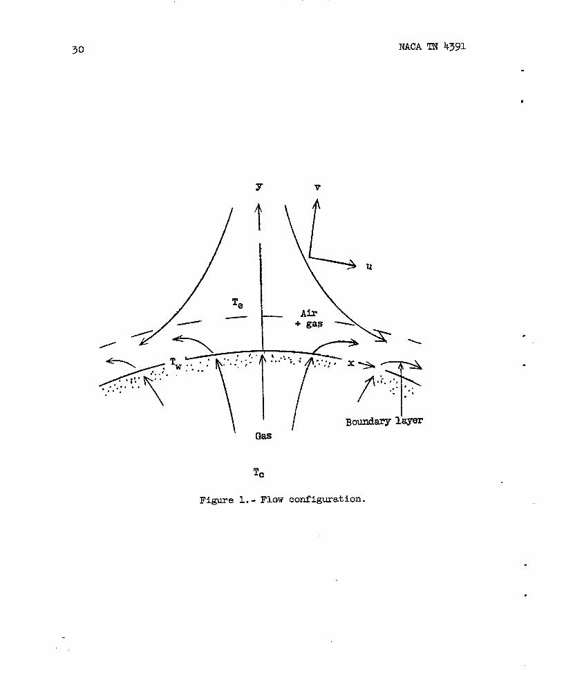
The flow considered is that shown in figure 1. In the steady statethe laminar boundary layer near the stagnation point is a thin layer offluid in which the velocity, temperature, and concentration of theforeign gas”vary rapidly from the external stream values to the wallvalues. In the neighborhood of the stagnation point the three super-imposed boundary layers (that is, the velocity, temperature, and con-centration boundsry layers) have constant, although different,thicknesses.
It is assumed that the component of velocity parallel to the wallis linesr in x and that the normal component of velocity, the tempera-ture, the concentration of the foreign gas, and the properties of themixture are all functions only of y, the distance normal to the wall.(This assumption results directly from the “similarity” nature of theflow and the absence of thermal and concentration gradients along thewall.) It is also assumed, consistent with the foregoing variation ofvelocity components, that the coolant gas is injected normally at thewall with a velocity independent of x.
When a given amount of coolant gas is inJected, it diffuses throughthe boundary layer and is convected with the air, as a mixture, underthe action of the pressure gradient imposed by the external flow and ●
the shearing stress due to the presence of the wall. The concentration—
of foreign gas at the wall is uniquely determined by the rate of injec-—
tion. The extent of the boundary-layer shielding depends upon the spe- ““ ‘“-cific heat of the foreign gas and upon the wall temperature as well asthe coolant and stagnation temperatures. ~ shielding also dependsupon the manner in which the coolant gas diffuses through the bound~
.+
layer. The analysis shows the relative importance of these quantities.
ANALYSIS
The method to be used is as follows: the wall conditions forcoolant injection are formulated in a simple manner (and the resultsare justified by a more detailed consideration of the flow within theporous wall presented in the appendix); use is then made of previous“exact” results for stagnation-point heat _*ransferwith no injection in
—.
order to determine the gross chsracteristi.csof the thermal and viscousboundary layers near the stagnation point. These results are then m“edin a simple approximate integral method to determine the effect of injec-tion on the heat transfer to the wall. *—
.
NACA TN k391 5
.
.-
The Coolant Flow
The boundary conditions at a porous wall through which a coolantis injected may be obtained very simply by ignoring the presence of thesolid pert of the wall; the justification for this is given in theappendti where more detailed considerations are made.
When the steady flow of coolant toward the surface of the wall isconsidered, the volume taken up by the solid wall being neglected, itis seen that there is a balance of diffusion and convection whichgoverns the flow of mass and
The transfer of mass is
heat within the wall.
given simply by
Pv= ~vw =a (1)
where & is constant.
The diffusion of air inward from the surface is balanced by theconvection towsrd the surface:
(1 - W)fi (2)
Diffusion of air Convection of airfrom surface towsrd surface
since W is the concentration of the foreign gas and (1 - W) is thatof air.
Similarly, the transfer of heat is given by
~ dT = CP,l(T - Tc)fiG
Diffusion of Convection of heatheat from toward surfacesurface
It is important to note here that, even though the specific heat of themixture % is given by
(3)
(with cp,l ad %,2
is Cp,l; in unit time
CP = Cp,lw+ CP,2(1 -w) (4)
constant), the value used correctly in equation (3)the heat transferred at any point y in a
6 NACA TN 4391
direction away from the surface is sufficient to raise an amount of.
foreign gas of specific heat Cp,l through _thetemperature range T - T=.9-
devaluatingequations (2) and (3) at the wall surface gives the fol-lowing boundary conditions which are required for the solution of theboundary-layer eqwtions:
[1-@)12 ~ = (1 - Ww)lidy w
[1kg SC -Tc)ilWw p;@w
(5)
(6)
Detailed study of the flow within the porous wall yields the smne bound-ary conditions. (See appendix.)
The Boundsry-Layer Integral Equations
The integral equations which describe the trmsfer of mass and heatin the boundsry layer are derived in a simple way without reference tothe general differential equations.
.-
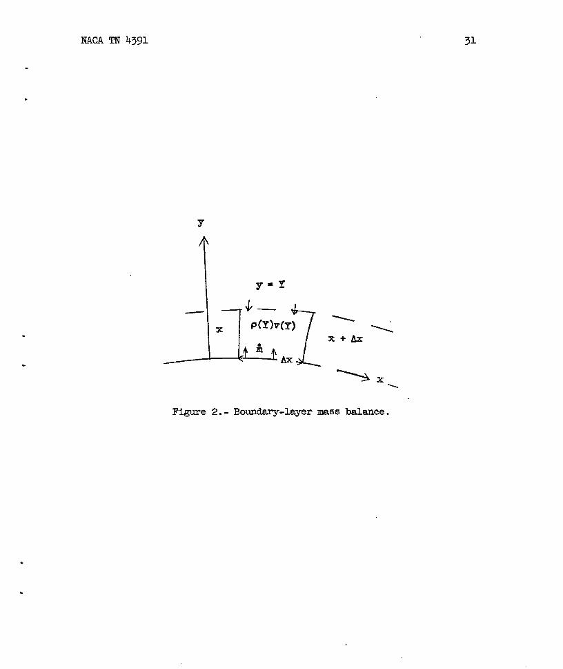
Consider a small rectangle of height Y (Y greater than anyboundary-layer thickness) and length Ax, in which p, W, and T areindependent of x, near the stagnation point of a two-dimensionalbody.(See fig. 2.) The continuity of mass maybe expressed as follows:
r..]Y
-[J]
Y+3(Y)V(Y) Ax + Ii& = pu dy W*
o X+AX o x
Flow in..from Injection Flow outexternal strean-” X+AX
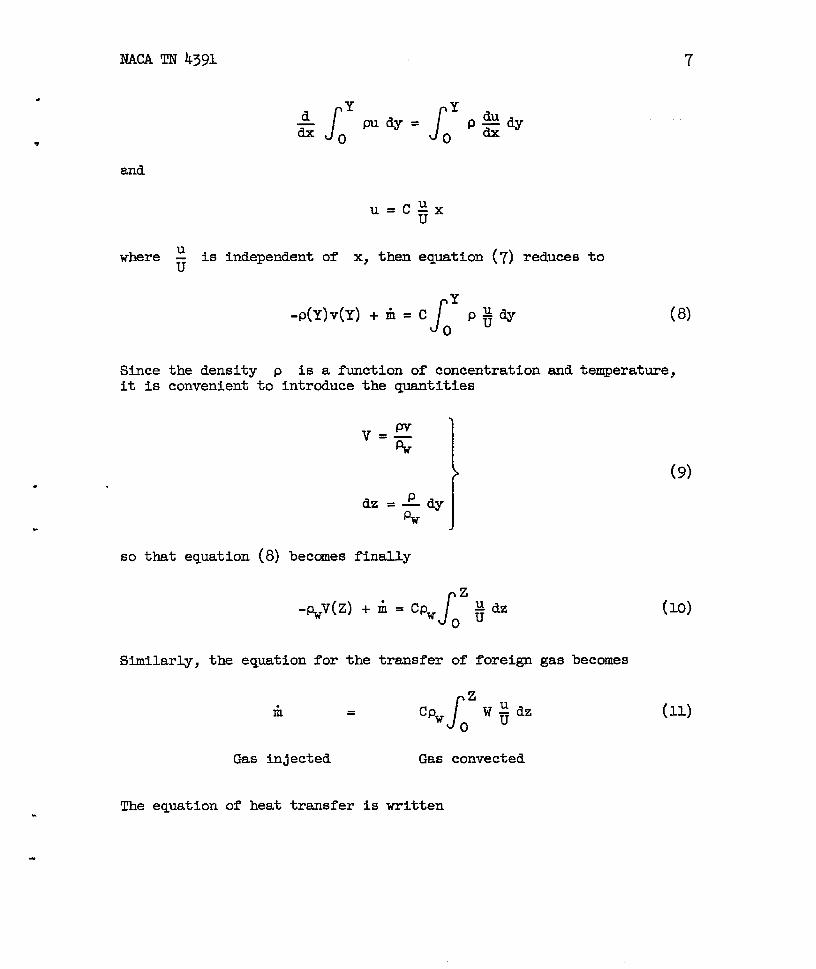
This equation, in the limit as & + O, becomes
nY-P(Y)V(Y) + Ii =~ Jdxow
When the form U = Cx of the external velocitythat
at Flow inat x
W (7)
is used and it is noted
.
.
. .
NAC!Am 4391
.
.
d
J
Y
J
Ypudy= ~ du
ZO #Yo
and
u= C;x
where
Sinceit is
~ is independent of x, then equation (7) reduces to
JY
-P(Y)V(Y) + Ii = co
P&9 (8)
the density p is a function of concentration and temperature,convenient to introduce the quantities
“zdz = :W
/
so that equation (8) beccmes finally
Jz
-P.J(z) + i = Cpw QdzOu
Similarly, the equation for the transfer of foreign gas becomes
i =
Gas injected
The equation of heat transfer.
Gas convected
is written
7
(9)
(lo)
(11)
8 NACA TN 4391
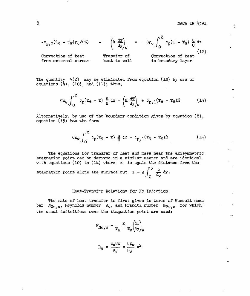
() J“p,2(Tf=-Tw~%v(z) - ‘f = ‘% ~zcP(T-TW)~dzw
(12)Convection of heat Transfer of Convection of heatfrom external stream heat to wall in boundary layer
The quantity V(Z) may be eliminatedequations (4), (10), and (11); thus,
from equation (12) by use of
Iz
cPw cp(Te - T)
()
;dz= k~*W
+ ~p,l(Te - TW)~o
(13)
Alternatively, by use of the boundary condition givenby equation (6),equation (13) has the form
Iz
C(+ cp(Te - T) ~dz = cp,l(Te - Tc)h (14)o
.
The equations for transfer of heat and mass near the axisymmetricstagnation point can be derived in a similar manner and are identicalwith equations (10) to (11) where x is again the distance from the .
J’Yp
stagnation point along the surface but z = 2 — dy.()%
Heat-Transfer Relations for No Injection
The rate of heat transfer is first given in terms of Nusselt num-ber NNU,W, Reynolds number ~, and Prandtl number Npr,w for which-
the usual definitions near the stagnation point are used:-
()%U,w=Te:q~w
“
9
.
.
NACA TN 4391
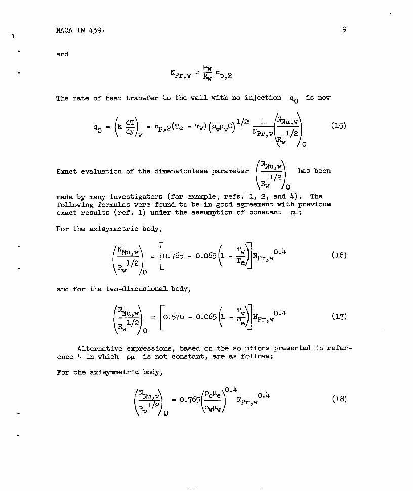
and
Npr,w = * cp,2
The rate of heat transfer to the wall with no injection ~ is now
()=kg
<)
1/2 1 Nu,w% @w=%2@e-T” Mp*9 —‘Pr,w 1/2
o
Exact evaluation of the dimensionless ()‘Nu,wparameter — has been1/2
%0
made by many investigators (for exsmple, refs.”1> 2, and 4). Thefollowing formulas were found to be in good agreement with previousexact results (ref. 1) under the assumption of constant W:
For the axisymmetric body,
()[‘Nu,w
(]
%= 0.765 - 0.065 1 -r ~n,w0”4
%1’2 ()e
and for the two-dimensional body,
(15)
(16)
(17)
Alternative expressions, based on the solutions presented in refer-ence h in which PU is not constant, are as follows:
For the axisymnetric body,
(18)
——
10
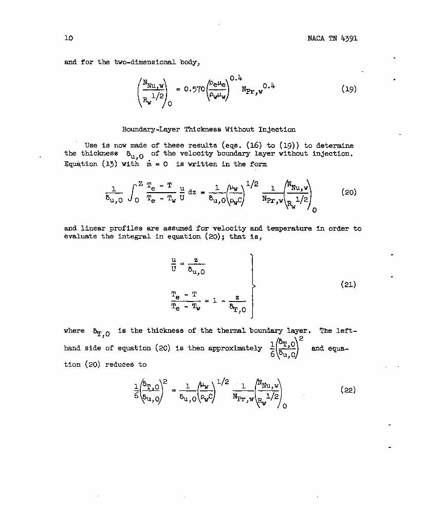
and for the two-dimensional body,
&z)o=”’’o(Rr”’Nprw
NACA TN 4391
.
.
(19)
Boundary-Layer Thickness Without Injection
Use is now made of these results (eqs. (16) to (19)) to determinethe thickness 5U,0 of the velocity boundary layer without injection.
Eq~tion (13) with & = O is written in the form
Iz~e-T
- -,&=& (&)’’2*&)o (20,1
%, o 0 ‘e
and linear profiles are assumed for velocity and temperature in order toevaluate the integral in equation (20); that is,
u z.=—u %, o
1
Te-T=1-—
Te - Tw %’,0I
.
(’l)
where ~,0 is the thickness
hand side of equation (20) is
tion (20) reduces to
of the thermal boundary layer. The left-
()2
1 5T,0then approximately -—6 5U,0
and equa-
(22)
.
.
NACA TN 4391 11
.
. ()‘Nu,wIf the value of when Nfi,w = 1 is signified by the super-1/2
%?~
script (1), then equations (16) to (19) show that
This eqwtioncoefficient.
u1/2%~
shows the effectWhen” Nw,w = 1,
are similar so that%;0 = ~;%, o
(23)
\%’”Jo
of the Prandt1 number oh the heat-transferthe thermal and viscous diffusive effects
thus, from equation (22)
%,o(-y’2=6&~) (24)
()pwc @
The nondimensional thicmess ~,. — is now assumed to be inde-+
pendent of the Prandtl number (since the momentum equation is onlyweakly dependent on the Prandtl nunher); thus, when equations (23) and(24) are inserted into eqyation (22), the following simple result isobtained:
%C,o= Nm,w -0.3%, o
This result is analogous to that for a flat plate (ref. 8):
(25)
5T— = NR,W -1/3au
.
NACATN 4391
Injection of Air.
Consider now the effect of injection of air into the boundary layer. .The boundary layer becomes thicker because of the increase in mass flowwhich results in reduced gradients in the boundary layer. In particular,the heat transfer to the wall is reduced since the heat convected par.allel to the wall in the boundary layer is increased.
The effect of air injection on the boundary-layer thickness isgiven by considering the mass flow in unit time per unit srea, asfollows:
Mass flowinjection
which gives
with ~SS flow with Massno in~ec_t_ion injected
(26) .
when linear profiles are assumed for u(
.
that is, (no injec-.n ;=&
\tion) and ~ =~
U% )(injection) .
It is assumedsince the ratio oflayer thickness depends on diffusive processes, that is, on the Prandtl-number.
that the relation given by equation (25) is stiI1.truethermal-boundary-layer-thicknessto velocity-boundary-
With %,1 = %,2 equation (13) maybe written by use of
equation (15) in the form
J‘Te-T~ , VW ‘f2 , NNU,W+ ;L3u ()[~dz=— — ——
0 ‘e -TWU au WC Npr,w?@1(~~c) 1/2
mcA TN 4391
Linear profiles forsiorisfor 5U (eq.
this equation, with
%.
13
temperature and velocity (eqs. (21)) and the e~res-(26] ) and 5U,0 (eq. (24))are used to simplify
the following result:
1 “Nu,w 1
L)(
Nu,w - ~-&N
)
-0.6—— =— —‘Pr,w
%@ ~,w 1/2 3 Pr,w * ’27)
o
In terms of the rate of heat transfer q, equation (27) has theform
=%-
Heat transferfor noinjection
(1 lN )-0.6- ~ Pr,w ~,2(Te - Tw)fi
(28)Boundsry-layer shieldingby convection
( INThe quantity 1 - –3 Pr,w)
‘0”6 (Te - Tw) may be interpreted as the
average temperature rise in the boundsry layer of the mass introducedat the wall surface. An alternative expression of this heat balance,obtained by using the boundary condition given by equation (6), is
When ~ is expressed
of equations (15) and (23),
Te - Tw
Te-Tc=
in terms of dimensionless quantities by use
equation (29) becomes
%r,w0.6 A
(~~c) 1’2
~Nu,w ‘1) + ~ fi
()p 33
0
(30)
14 NACA TN 4391
Eqyation (30) may be used to determine the rate of injectionrequired to maintain the wall temperature Tw at a given desired value
when Te and Tc exe specified.
Before proceeding to considerations of injection of foreign gas,the results given by eqution (27) are compared with available exactsolutions as a check on the validity of the several simplifying assump-tions that have been made.
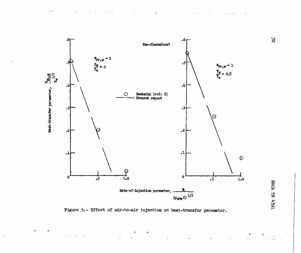
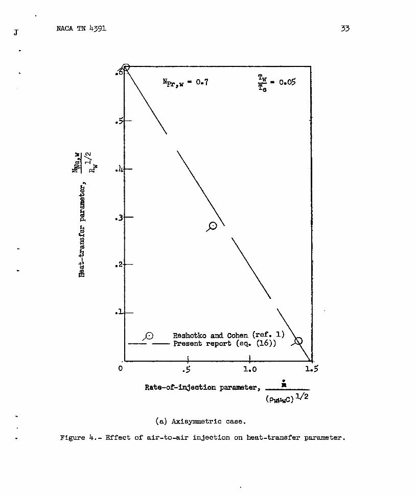
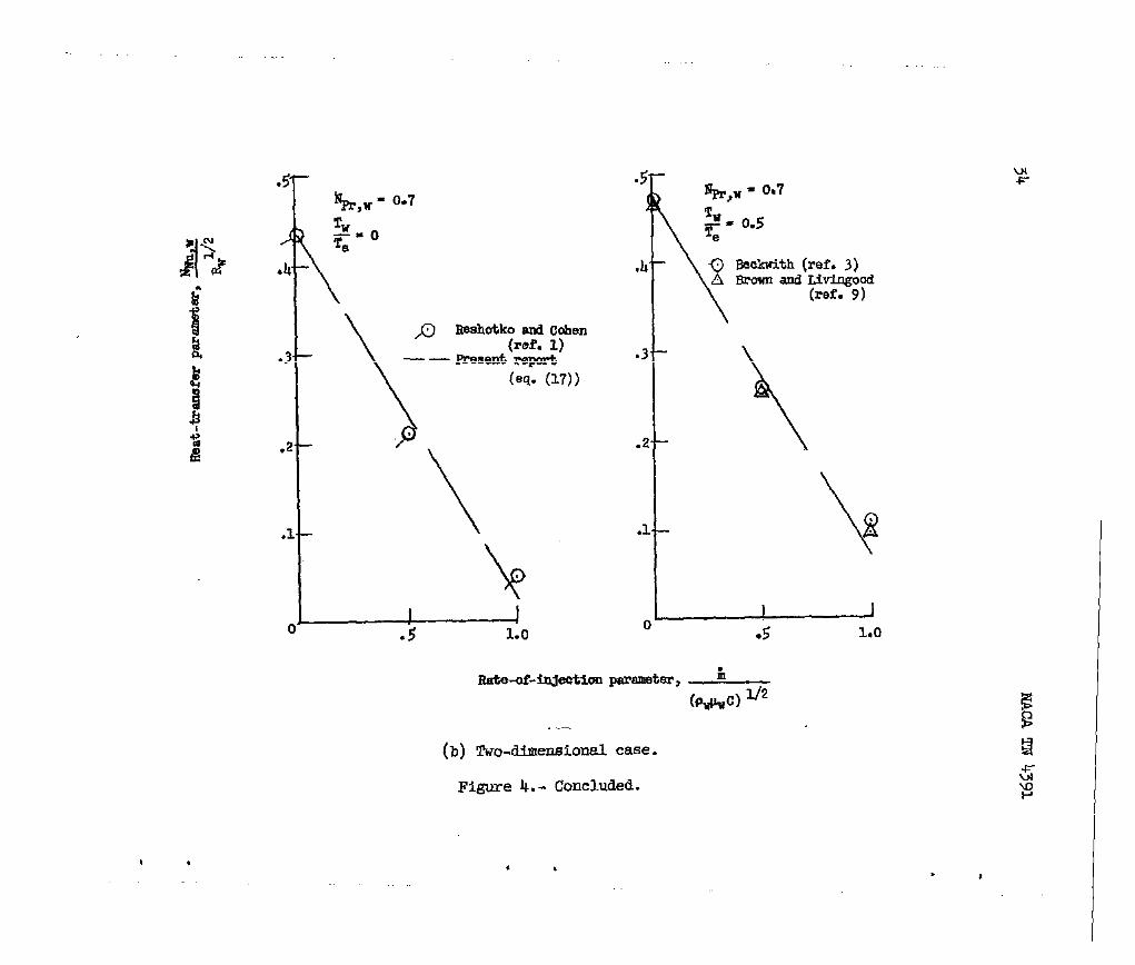
Firstly, under the assumption of constant PIL,equations (I-6)(eq. (17) for the two-dimensional flow) and (27) are used to give
N’NU,w
pas a fumction of t-hedimensionless ra~e”of inass,inJection
lil . A comparison of these results with the results of refer-
(p##) 1/2
ences 1 and 3 shows very good agreement except for the extreme ratesof injection with Prandtl number equal to unity. (See figs. 3, 4,and 5.)
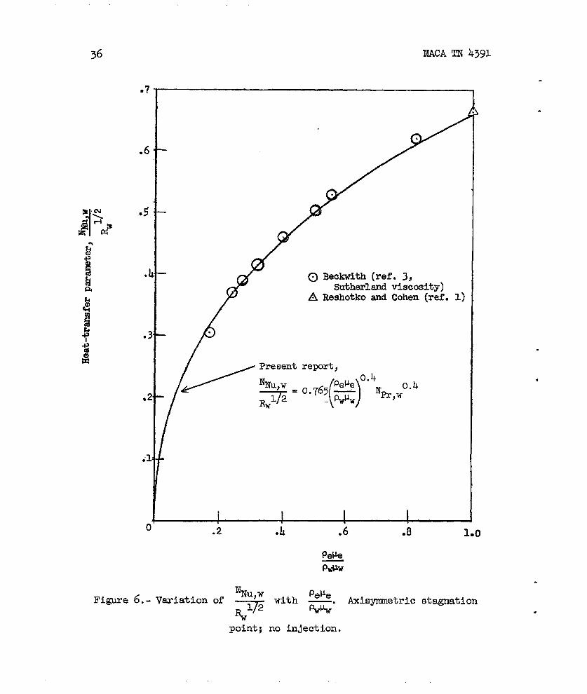
Secondly, for variable ~, equations (18)(or eq. (19)) and (27)are used and the results are compared with those of references 3 and 4.For a Prandtl number of 0.71 and no inJection reference h gives, for
“
the axisymmetric case,
and the present report
.
gives (fromeq. (18))
‘Nu)w PeVe 0-4
()
= 0.667 —
%1/2 P*
A comparison of the results obtainedby use of equation (18) with theresults of reference 3 in which the Sutherland viscosity law was usedis presented in figure 6.
.
The effects of injection are also compsred when PV is variable;again good agreement is found except for the high injection rates.(See fig. 5.)
..
.
.
.
NACA TN 4391 15
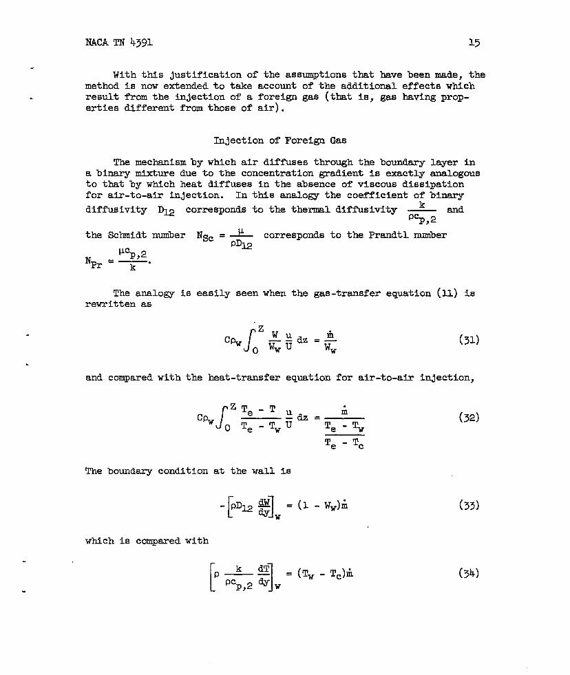
With this justification of the assumptions that have been made, themethod is now extended to tske account of the additional effects whichresult from the injection of a foreign gas (that is, gas having prop-erties different from those of air).
I@ection of Foreign Gas
The mechanismby which air diffuses through the boundary layer ina binary mixture due to the concentration gradient is exactly analogousto that by which heat diffuses in the absence of viscous dissipationfor air-to-air injection. In this analogy the coefficient of binsry
diffusivity D~ corresponds to the thermal diffusivity ~ and5,2
the Sclmidt number Nsc = ~ corresponds to the Prandtl numberPDE
Uu c1“ P)=
‘Pr ‘~-
The analo~ is easily seen when therewritten as
and compared with the heat-transfer
JZTe-T
C!pwOTe-Tw
gas-transfer equation (11) is
fi=—Ww
(31)
equation for air-to-air inJection,
Iil:dz=—u
(32)Te-~
Te - Tc
The boundary condition at the wall is
-p= *]W =(1 -Ww)i (33)
which is compared with
Fe51:(Tw-Tc)’
(34)
16 NACA TN 4391
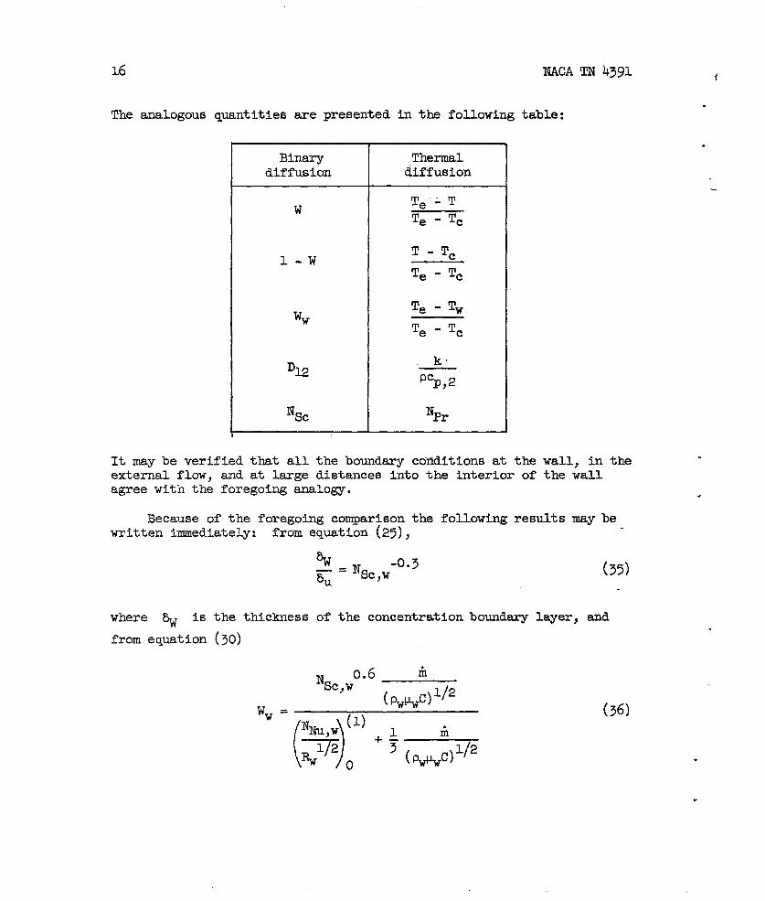
The analogous quantities are presented in the following table:
Binarydiffusion
Thermaldiffusion
T. -T
T - Tc
Te - Tc
Te - Tw
Te - Tc
k
P53,2
‘Pr
It may be verified that all the boundsry conditions at the wall, in theexte~al flow, and at large distances into the interior of the wallagree with the foregoing analogy. .
Because of the foregoing comparison the following results may bewritten immediately: from equation (25),
%— = Nsc,w-0.3Eu (35)
where ~ is the thickness of the concentration boundary layer, and
from equation (30)
0.6 Ii‘Sc ,W
( p##) 1/2Ww=
N~u,w(l)+~ A
()p
o~ (WC)V2
(36)
NACA TN 4391.17
.
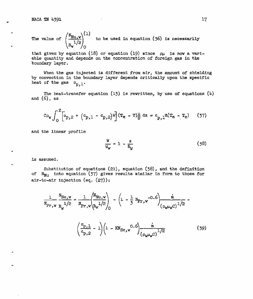
The value ofNNU ~ (1)
( ‘)
to be used in equation (36) is necessarily
. #2 ~
that given by equation (18) or equation (19) since p~ is now a vsri-able quantity and depends on the concentration of foreign gas in theboundsry layer.
When the gas injected is different from air, the amount of shieldingby convection in the boundsry layer depends critically upon the specificheat of the gas Cp,l”
The heat-transfer equation (13) is rewritten, by use of equations (4)and (6), as
and the linear profile
“
w—=Ww 1-: (38)
is assumed..
Substitution of equations (21), equation (38), and the definitionof NNU into equation (37) gives results similar in form to those for
air-to-air in~ection (eq. (27)):
( )(Cp,l ).
-11cp,2 - ‘s’~w0”6 *
(39)
18
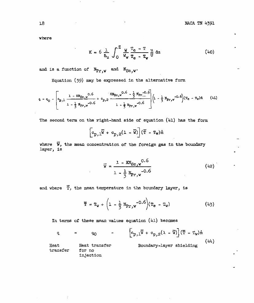
where
Jz
K=6$ yTe-T tzdzu OwwTe-~~
NACA TN 4391
(40)
and is a function of NPr,w ~d Nsc,v.
Equation (39) maybe expressed in the alternative form
[
0.6 %c,w --”10.6-$ Nti-o.6
1 -%c,w(-~H~=~- ~,1 + %,2 1
)“0”6 (Te - Tw)iI (41)
1 J%,W-O.G -0.63 Pr,w
1 -* %,W
The second term on the right-hand side of equation (41) has the form
[Cp,ly+ CP,2(1
where F, the mean concentration oflayer, is
. ..
-1R) (~- Tw)fi
the foreign ga8
1 - %c,w0.6
ii=1 -AN -0.6
3 Pr,w
in the boundary
and where ~, the mean temperature in the boundery layer, is
T (=Tw+ 1-~11 )‘0”6 (Te - Tw)3 Pr,w
In terms of these mean values equation (11) becomes
[~,lii + CP,2(I - fi)] (y - Tw)iI
.
.
(43)
—
.
(42)” “
(41+)Heat Heat transfer Boundary-layer shieldingtransfer for no
injection .
.
NACATNk3gl
. Thus, in order to achieve the maximum smount of shielding for giventemperature conditions and mass inJection, Cnal should be made as
. large asble; if
then fi
T - TV
.
.
Te - TV
that F
19
possible and, in ad~tion, ~ shoul~’be made as large as possi-
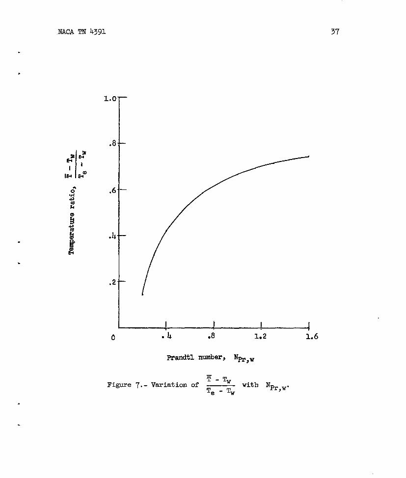
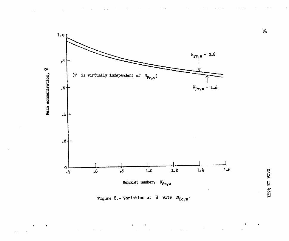
Cp,l’ cp,2 then W shouldbe large, and if Cp,l < cp,2should be small. The variations with Npr,w and NSC,W of
and ~ are s&wn in figures 7 and 8, respectively. It is seen
increases as %c ,W decreases and that ~-%Te - Tw
%r,w increases.
Maximum shielding in the boundsry layer is therefore
increases as
achieved when,—for cp,l> cp,2~ ‘Pr,w is large and NSC,W is small and, for
Cp,l < Cp,z> Nm,w IS lsrge and NW,W is large.
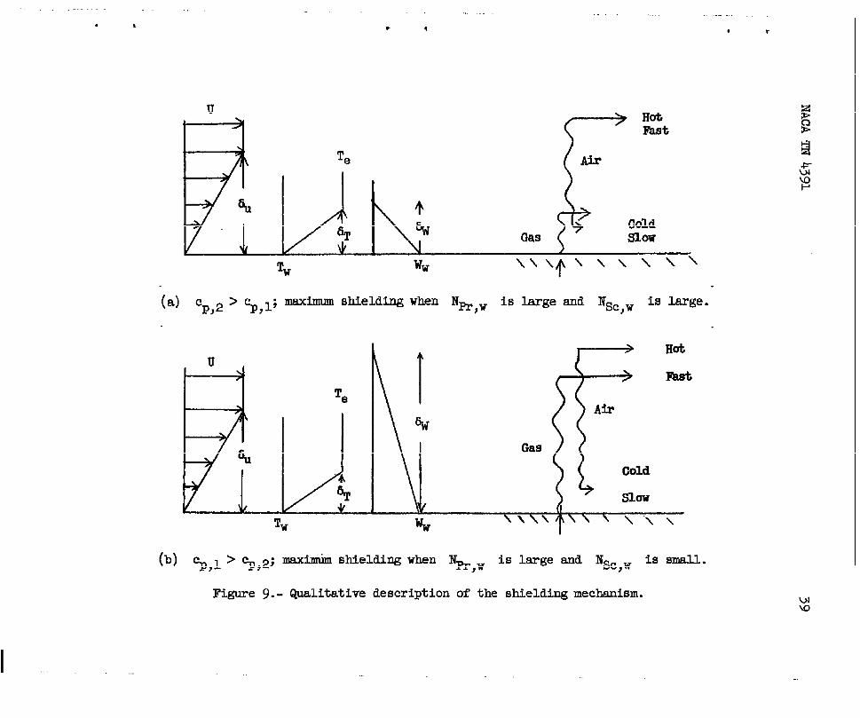
These diffusive effects on the shielding sre explained qualitativelyin the following way (fig. 9): the convective shielding is most effi-cient when the gas of higher specific heat is transported in the regionsof highest temperature and velocity, that is, in the part of the boundarylayer farthest from the wall.
Equation (27) shows that when Nm,w iS Wge the ve~ocitY boun~
layer is thicker than the thermal boundary layer and thus more of thehot gas mixture is convected. When %,1 > %,2 ‘d NSC,W is smau,equation (35) shows that the concentration-boundary-layerthickness isgreater than the velocity-boundary-layer thickness - that is, the foreigngas of higher specific heat diffuses qtickly through the boundeq l~erbefore being convected. On the other hand, when ~,1< %,2 and NSC,W
is large, the foreign gas remains near the wall and displaces the air ofhigher specific heat into the hot fast region where it is convected.
An important consideration in any cooling system is the weightpenalty which is incurred in order to maintain the wall at a desirabletemperature. The relation between the rate of mass flow fi and thetemperatures Te, Tw, and Tc is obtained by substitution of the
expressions
20
and
NACA TN 4391
.
H~=cp,2(Te -Tw)(~C)l/2~NNu’w
‘-N #/2 o
(from eqs. (6) and (13), respectively) into
tution results in the following expressions
( ))
%u,w :or equation (19) is used for~wl/2 o
For axisymmetric flow,
equation (41). This substi-
(when either equation (18)
P#e 0“4
,,()
0.765 — ‘Pr ,W-0.6
%#w(~~wc)l/2cp,2(Te -Tw)
G= (45)cp,lOw - Tc) + ~(~ - Tw)
and for two-dimensional flow,.
PeVe 0“4
(QJ
0.570— ‘Pr,W‘0”6(~C)1’2cp,2(Te -Tw)
Iii= (46) -cp,~(Tw - Tc) + ~(~ - Tw)
—
where
(47)~p =cp,l~+ cp,2(l -w
Probably the most important parameter is the total effective heatcapacity Heff of the coolant; this parameter is a measure of the total
heat absorbed when tiit mass of the coolant is used and is defined as
H % CP,l(TW - Tc) + ~m -Tv)eff=~= (48)
NACATN 4391
METHODOF U!JXUUITIONOF RATEOF MASSINJECTICN
21
The problem of most interest from practical considerations is thatof determining the rate of mass injection fi necessary to achieve adesired wall temperature Tw when the stagnation temperature Te and
the coolant temperature Tc are given. This calculation is made com-
plicated by the dependence of the mean specific heat ED (required for
eq. (45) or eq. (46)) on the rate ~;easssin ection; bo~h these quantitiesdepend on the concentration Ww. . t47), (42), ~d (35). )
The following method, however, gives results with relatively littlecomputation:
(1) The parameters Nm,w and NSC,w are found in terms of Ww
for the particular binary mtxture under consideration. (Simple empiricalmethods are given in ref. 6.)
(2) Equation (43)
‘-% ~ IN -0.6Te-Tw= - ~ Pr,w
is usedto give ~ (fig. 7)..
(3) Eqwtion (42)
1 0.6- %c,w
R=
1 - + ‘Pr,w-0.6
is used to give ~ (fig. 8).
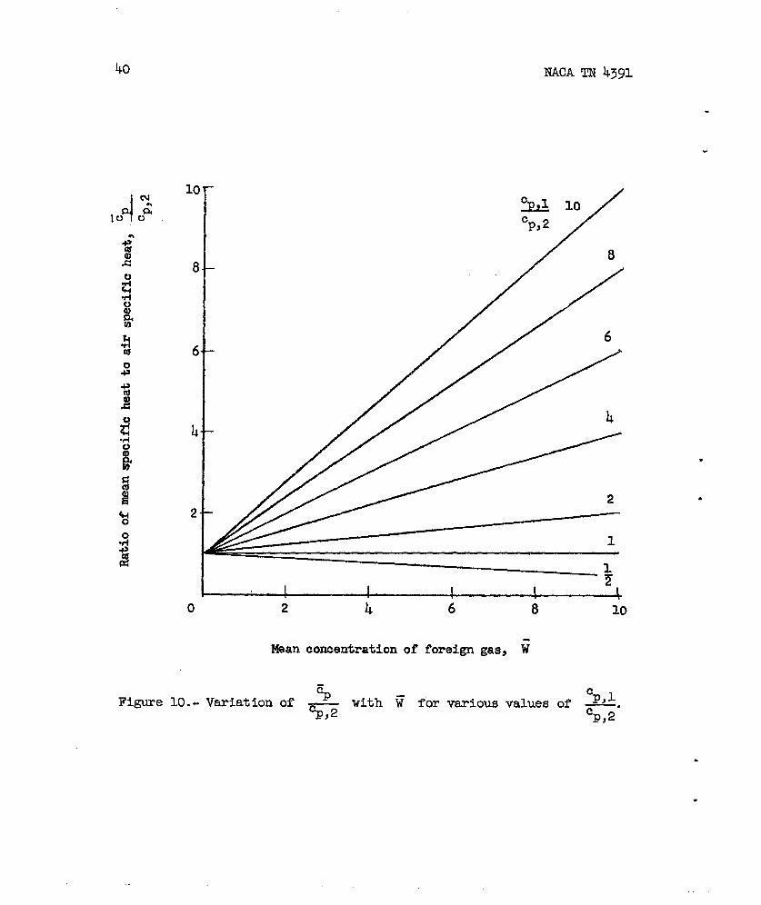
(4)Equation (47)
then gives ‘P (fig. 10).
22 MCA TN 4391
()0.4
(5) A plot of ~ ~ against WV can now be made(%%C)l/2 pe~e
from the results of the substitution of equations (43), (42), and (47)into either equation (45) or eq~tion (46)*
(6) A second plot of “%% 0“4
()against WV canbe‘*=
obtained aE a result of converting equation (36) into the following formfor the axisymmetric case:
Ii %%? 0“4()o. 765ww
1/2 PeVe(Plfwc) —
or into the following form for the
=0.6
%c ,WlV
-Tw
two-dimensional case:
.4Ii ()pw%r”’.
(P##)1/2 ‘eve
o. 570w~
0.6%c,w
Jww3
(49)
.
.
(5”).
The intersection of the curves found in steps (5) and (6) gives WV and.
(w)0.4
Ill .1/2PelJe
(*C)
(7) ~owj P@+ can be fo~d frcsn Ww and Twjand PeVe fromexternal conditions; thus, fi canbe calculated.
Step (7) may be omitted if the approximation
is made, in which caseh
is given directlyby steps (5)( p*c)l/2
.
.and (6) .
NACA TN 4391 23
.
.
.
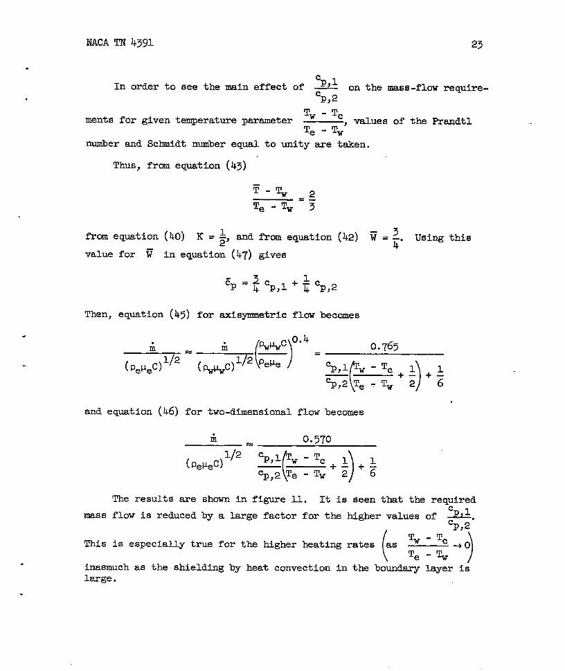
In order to see the main effect of CP,l on the mass-flow require-cp,2
Tw - Tcments for given temperature psrameter values of the Wandtl
Te - Tw’
number and Schnidt number equal to unity are taken.
Thus, frmn equation (43)
from equation (40) K =$ and from equa.tion (42) F =2. Using this4
value for ~ in equation (47’)gives
Then, equation (45) for axisymnetric flaw becomes
i Ii ()*C 0“4=
(p&ec)l’2(p+#)l/2‘ewe ‘
and equation (46) for two-dimensional flow
0.765
i 0.570%
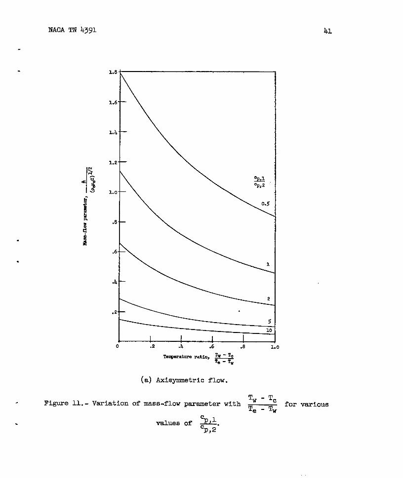
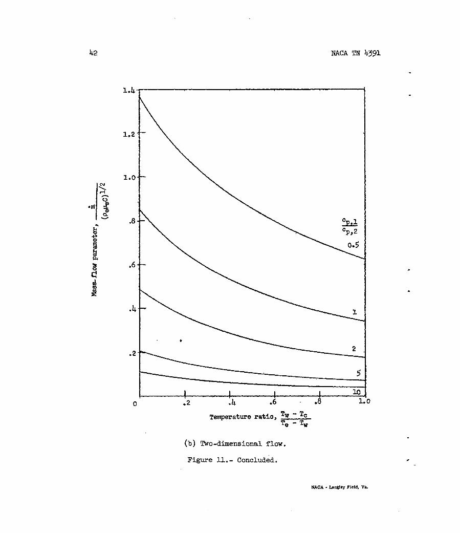
The results are shown in figure Il. It is seen that the required
mass flow is reduced by a large factor for the higher values of Cp,l.
cp,2.
(This is especially true for the higher heating rates as
)
%-TC+O
Te-~
inasmuch as the shielding by heat convection in the boundsry layer islarge.
.
24 NACA TN 4391
CONCLUDING REMARKS
.An approximate analysis has been presented whereby the reduction
in heat transfer near the stagnation point ~y be calculated with littledifficulty when the coolant properties are known. The agreement withavailable exact solutions for air-to-air injection is extremely good
,,
in view of the simple approach employed, and the qualitative trends ofthe results for foreign-gas injection in e@~aining the shielding mecha-nism suggest that-the approximate analysis will generally give reliableresults. It is expected that the simplifie~”calculation which showsthe dependence of the coolant mass requirement on wall temperature andcoolant specific heat will provide a good estimate for engineeringpurposes. —.
.
The conclusions of the analysis are summarized briefly as follows:
Maximum boundsry-layer shielding is achieved when the gas of higherspecific heat is convected in the hot fast-moving part of the boundarylayer farthest from the wall; this requires that the coolant gas intro-duced have
(a) High specific heat compared with that of air
(b) High binary diffusivity (that is, small Schmidt number)
(c) Lerge Prandtl number..
Of these three properties the first is the most important, whereasthe diffusive effects are of secondary importance.
.
—
Langley Aeronautical Laboratory,National Advisory Committee for Aeronautics,
Langley Field, Vs., July 3, 1958.
.
T
.
.
.
.
l?ACATN 4391
APPENDIX
FLOWWITHINTBEPOROUS
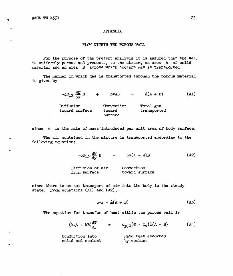
For the purpose of the present analysis
25
WALL
it is assumed that the wallis uniformly por&s and presents, to the-stream, an sxea A of solidmaterial and an area B across which coolant gas is transported.
The manner in which gas is transported through the porous materialis given by
~B-PDM dy + pvwB = ti(A+ B)
Diffusion Convection Total gastoward surface toward transported
mrface
(Al)
since fi is the rate of mass “introducedper unit area of body surface.
The air contained in the mixture is transported according to thefollowing equation:
-PDW $$B =
Diffusion of airfrom surface
since there is no net transport of airstate. From equations (Al) and (A2),
PV(l -W)B
Convectiontoward surface
into the body in the steady
pvB = k(A + B)
The eq~tion for transfer of heat within the porous wall is
(M)
(A3)
(A4)
Conduction into Rate heat absorbedsolid and coolant by coolant
.
26 N4CA TN 4391
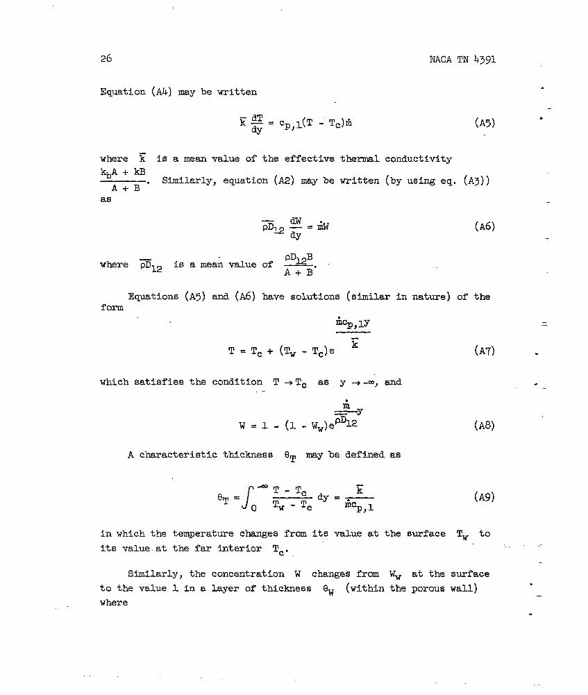
Equation (A4) may be written
(A5)
—&
where ~ is a mean value of the effective thermal conductivity
‘b! + ~. Similarly, equation (A2) may be written (by using eq. (A3))—
A+i5
as
where mu is a mean value
Equations (A5) and (A6)form
(A6)
have solutions (similar in nature) of the
fi~,lY
T=ii
Tc + (Tw - Tc)e
which satisfies the condition T +Tc as y +-m, and
A characteristic
in which the
its valueat
thickness Qm may be defined as
J-CQ
.gT=T-Tc
dyE=-
0 ‘w-Tc m~,l
(A7) .
(A8)
(A9)
temperature changes from its value at the surface TV to
the far interior T=.
Similarly, the concentration W changes from
to the value 1 in a layer of thickness QW (within
where
—.
.
.-
Ww at the surface
the porous wall)..
.
NACA TN 4391 27
.
&
.
.
J-l-w PDW8W = dy=—
0 l-WW &(Ale)
BIt is seen that both thicknesses depend on the ratio –. It is desirable
Ato limit the relatively high te,~rature region within the wall to anarrow region nesr the surface; the specific heat ~ must be lsrge.and ~ must be small, that is, both kb and k should be small. Con-
siderations of the bounda&y-layer flow outside the wall also lead to theconclusion that the specific heat %,1 should be Mge ~d k shofid
be small (so that the Prandtl number-&ybe as large as possible).these requirements result in two desirable features:
(a) Confinement of the high temperatures within the body to anarrow region near the surface and
(b) Maxhum convection of heat away from the stagnation pointshown in the body of the report)
The conditions at the surface as it is approached frcm withinwall are given as follows:
From equations (A2) and (A3)
-(PDJ-23.:= (1 - Ww.)&(A + B)
and from equation (A4)
()(k#+ld3) ~w w-
= %,l(TW - Tc)~(A + B)
Thus,
(as
the
(ml)
(Au?)
where the subscript w- denotes that the surface is approached throughnegative values of y. The rate of heat transfer from the stream
boundary layer is()kg (A+
@w
(eq. (A12)) becomes
.
Thus, there is a discontinuity
B) so that the boundsry condition
= ~,dTw - Tc)fi (~3)
in ~ at the surface when ~ ~ kb..
28 NACA TN 4391
Similmly, the condition of no net transfer of air to the body is .
given by
+% :):Aobtained when the surface isSince
●
+ B) = (1 - Ww)~Vw(A + B) (A14)
approached through positive values of y.
.
~-vw- = il= ~v~
equation (A14) may be written as
-P2$i)w= (1 - Ww)il
It is noted that v is discontinuous since there is a disc~tinuity
in the srea available for convection given by the ratio The=“
concentration gradient dW~ is also discontinuous for the same reason;
this is expectedly anal&y with the temperature gradient ~. Equa-—
tions (A13) and (A15) are seen to be identical with equations (3) and(2) when evaluated at the wall.
.
.
NACA TN 4391 29
REFERENCES
1. Reshotko, Eli, and Cohen, Clarence B.: Heat Transfer at the ForwardStagnation Point.of Blunt Bodies. NAC!ATN 3513, 1955.
2. Morduchow, Morris: Analysis and Calculation by Integral Methods ofLsminsr Compressible Boundary Layer With Heat Trapsfer and Withand Without Pressure Gradient. NACA Rep. IZ45, 1955.
3. Beckwith, IvanE.: Similsr Solutions for the Compressible BoundaryLayer on a Yawed Cylinder With Transpiration Cooling. NACA TN 4345,1958.
4.Fay, J. A., and Ridden, F. R.: Theory of Stagnation Point HeatTransfer in Dissociated Air. Jour. Aero. Sci., vol. 25, no. 2,Feb. 1958, pp. 73-85, 121.
5. Hall, Newman A.: Flow Eqtitions for Multicomponent Fluid Systems.Pm% I - General Equations. Part II - Binary Boundary Layer Equa-tions. Tech. Rep. No. 2 (Contract No. AF-18(600)-u26), HeatTransfer Lab., Univ. of Minnesota, Aug. 1955.
6. Carlson, W. o., and Schneider, P. J.: T&ansport Properties forBinary Gas Mixtures. Tech. Rep. No. 7 (Contract No. AF-18(600)-1226),Heat Transfer Lab., univ. of Minnesota, Jan. 1956.
7. Roberts, Leonard: A Theoretical Study of Stagnation-Point Ablation.NACA TN 4392, 1958.
8. Fluid Motion Panel of the Aeronautical Research Committee and Others:Modern Developments in Fluid Dynamics. Vol. II, S. Goldstein, cd.,The Clarendon Press (Oxford), 1938, pp. 623-627.
9. Brown, W. Byron, and Livingod, John N. B.: Solutions of Lsminar-Boundary-Layer Equations Which Result in Specific-Weight-Flow ‘Profiles Locally Exceeding Free-Stream Values. NACA TN 2800, 1952.
.
.
30 NACA TN 4391
Y v
TC
Figure l.- Flow configuration.
.
NACA TN 4391 31
Y
.
.
--s.
Figure 2.- Boundary-layer mass balance.
*
.
.
.
.&-
‘“-\o——
.3
.2
-1
.1 —
J *.
0-●5 1.0
BeOk!dth (ref. 3)F7eseuhmpOrt
.{
●!
.1
.:
.2
.1
0
Ratlxlf-illjectlmpar$meter,—
(M&’
.,\,
0
.5 1.0
Figure ~.- Effect of air-to-air injectionon heat-tranaferpamlmter .
, , , . .,“
J luK!Am 4391
.
33
.
*
.
.
.● ✎
0
—‘\ P
—
D ‘JRReshotko and Cohen (ref. 1)— — Resent report (eq. (16))
.5 1.0 1.5
Rate-of-injectionparameter, &(P@@) @
(a) Axisymmetric case.
Figure 4.- Effect of air-to-air injection on heat-tramsfer parameter.
.3
.2
●I
(
$,w = 0.7
TV
<-Q
\
J@ lmshotk~ry yisn
—— Prment rspart
(% (17))
.
\
\
J’?
.
.
.
\
Q Bedmith (ref. 3)hlwwnsndLii~
.5 1.0
Rate-of-illjeotim pmmtm, -.J!--(P*C) ~2
. .—
(b) !lko-dlmemioti case.
Figure 4.- ConQua&.
. :
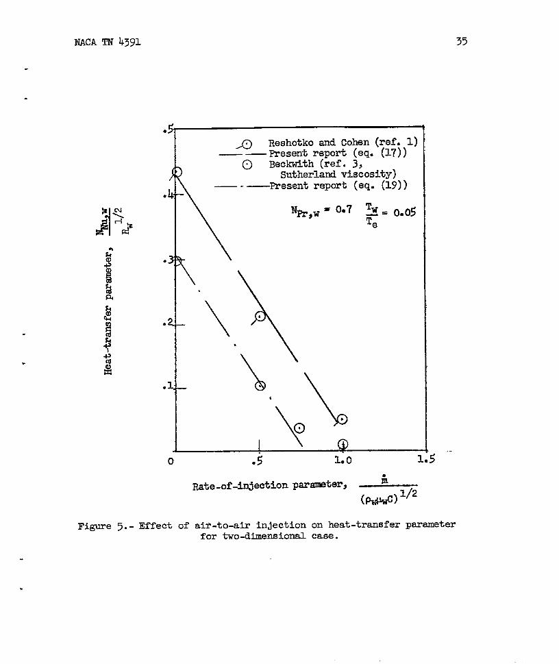
NACATN 4391 35
.
~ Reshotko and Cohen (ref. 1)— — present report (eq. (17))
)~ Beckwith (ref. 3,
\
Sutherlati viscosity)— -—Present report (eq. (19))
\
\.
-\.
%,w = 007 Tw—= 0.05Te
o
Figure 5.- Effect of
1.0} . .
1.5
iiRate-of-injection par-ter, _
(*) U2
air-to-air injectionfor two-dimensional
on heat-transfer parametercase.
36 WCA TN 4391
,● I
.(
.
●
●’
K ~ Beckwith (ref.3,Sutherlandviscosity)
~Reshotko and Cohen (ref.1)
%,0.4
()
PeWe= u. pJ3—
,p -%% “’’”0”4
(J .2 .4 .6 .8 1.0
.
.
‘Nu,w with pe~eFigure 6.- Variation of
p W*Axisymnetri.cstagnation
point; no injection.
,NACATN 4391
1.0
.8
.6
.r!l
.2
37
Prandtl number, %,w
~-TwFigure 7.- Variation of
Te - TV ‘ith %r,w”
1.0
.8
c=
.6
.1
.,
(ii is independent
~,W = 1.6
[ I I ! ! I
.6 ,8 1.0 1.2 1o11 1.6
Figure 8.-
. n
. .
I
uHotFast
Te
Cold
slow
%w~ \\\
“(a) CP,2 > Cp,l; m=imum shielding when NW,W iS ~ge =d NSC,W IS @ge.
u
E
%
Te
(> Hot
> Fast
A&
Gaa
Cold
slow
%\\\\ \ \ \“\\
(b) ~,1>%,2/ - maxhmim shielding when Nfi,w is large and NSC,W is small.
Figure 9.- Qualitativedescription of the shielding mechanism.
40 NACA TN 4391
.
.
--
0
Figure lo. -
~ 10c_ .-) /p,c
2
2 k 6 8
Mean concentrationof foreign gas, W
‘P“f ~
with ~ for various values
10
Cp,lof —.cp,2
.
.
.
.
NACA TN 4391 41
3..8
1.6
1.4
1.2
1.0
.0
.6
.IL
.2
( .2 .l! .6 .8 1.0
Tqmratumratio, _e u
(a) Axisymmetric flow.
Figure 11.-Tw - Tc
Variation of mass-flow psrameter with ~ for variouse - Tw
values of W.cp,2
42
1.4
1.2
1.0
.8
.6
.4
.2
0
NACA TN 4391
.
.
) I I I 10
.2 .-h .6 .8 1.”0
Tempsratwe ratio,‘w - Tc~
.(b) Two-dimensional flow.
Figure 11.- Concluded. “
NACA -Langley ~elfJ, WL