Embed Size (px)
Citation preview
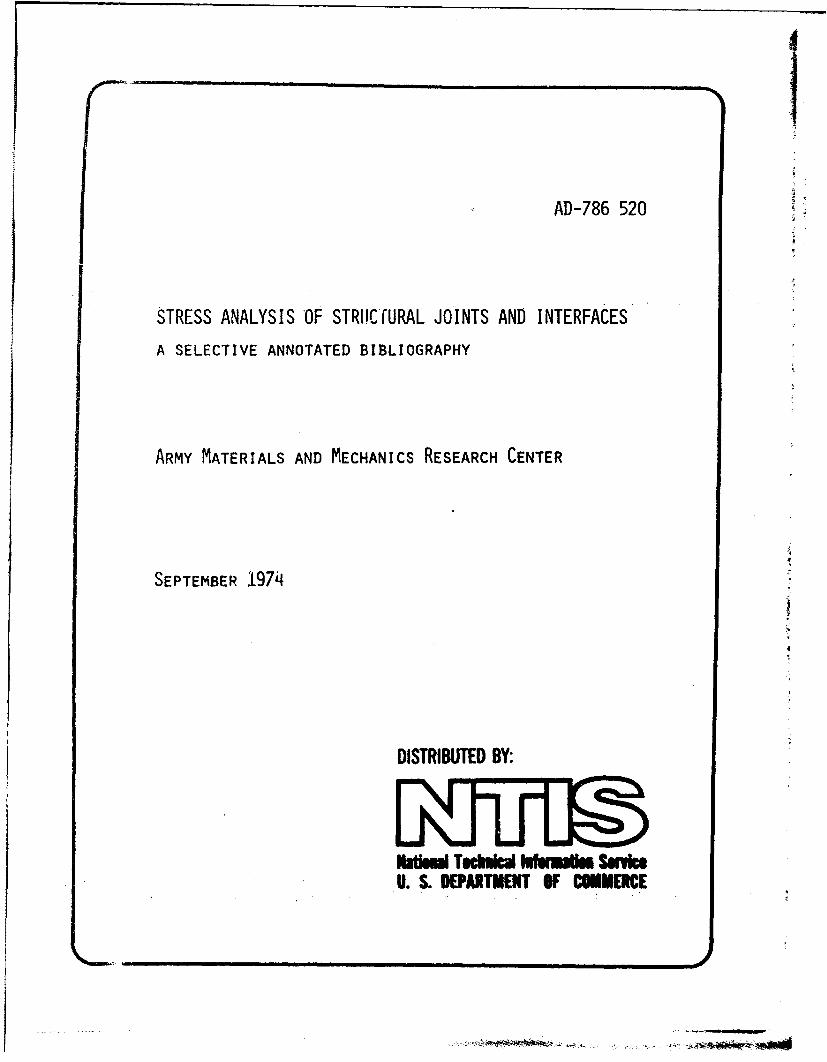
AD-786 520
STRESS ANALYSIS OF STRI'C URAL JOINTS AND INTERFACES
A SELECTIVE ANNOTATED BIBLIOGRAPHY
ARMY MATERIALS AND MECHANICS RESEARCH CENTER
SEPTEMBER 1974
4
DISTRIBUTED BY:
Natisul Tochulcal lufumiu Servic.. S. •PARTMENT OF COMMERCE
UNCLASSIFIEDSICUMIgTV CLAWFII'CAYION OF Tut! PAGE (Uften Dae ff"e...tj
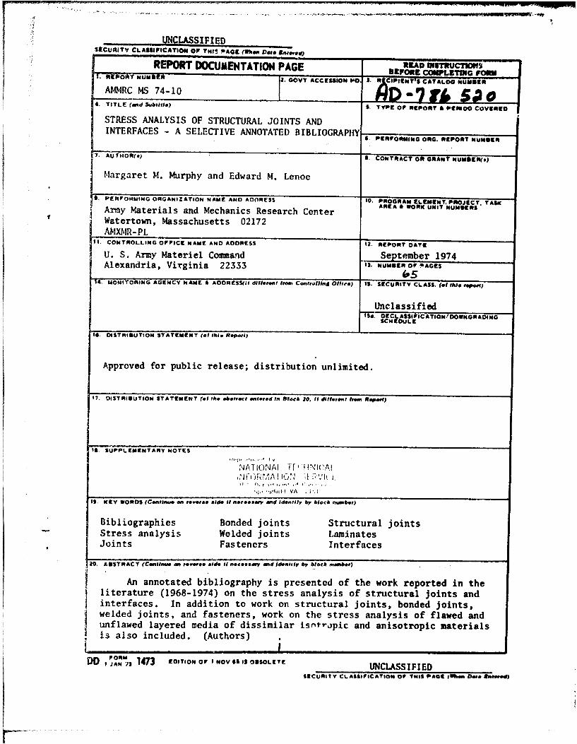
REPORT DOCUMENTATION PAGE M3UADI 9 1•=WC 'I1lroo-T NUM11 , GOVT ACCESSION 1O S. 3It ClPlENY'S CATALOG 61UINDER
AMiRC MS 74-10 "7 7t, I4. TITLE (and Sublitle) S. TYPEN OF pompONT o P O VIBES
STRESS ANALYSIS OF STRUCTURAL JOINTS ANDINTERFACES - A SELECTIVE ANNOTATED BIBLIOGRAPHY
6. Pan.I lo*M1i140 Oita. IRCPORiT MqUNIIER
7. AUTHOR(*) 6. CONTA ACT Olt GRANT NUMERN(s)
Margaret M. Murphy and Edward M. Lenoe
S. PERFOI.RMING 04GANI ZATION NAME ANo AolRESS ,0. PROGRAM ELENTPROuECT TASKAMCEA A WOmRK UNI T NMSArmy Materials and Mechanics Research Center
Watertown, Massachusetts 02172AMXMR- PL
II. CONTROLLING OFFICE IsNAME AND ADORESS 12. REPORT OATE
U. S. Army Materiel Comm&nd September 1974Alexandria, Virginia 22333 I1. HuNMER OffAPAGES
MA. UONITORING AGENCY NAME & ADORESS(lI diffeoren from Contrllini4 Oflfie) IS. SECURITY CLASS. (of INIs tiporf)
Unclassifiedt5d. DErCL- AlSS FI C ATI ON D OWNqGRqA DING
SCHED ULEr
I$. DISTMSYUTION STATEMENT (of fMt. Report)
Approved for public release; distribution unlimited.
17. OISTRIMUTION STATEME0NT (of thi .botvree entered In hlock 20. II ilfirnt from. RiPpoff)
IS. SUPPLEMENTARY NOTES
NATIONAI TF" HNWcAl,1 ) L• lul 1-' I Vh i
, I VA • i'V
It. KeY WORDS (Continue on rovers@ side if necisslly ad Identify by block number)
Bibliographies Bonded joints Structural joints
Stress analysis Welded joints LaminatesJoints Fasteners Interfaces
Z0. AIISTRACT (Conlinue an reersoi side If necemewa, mnd iden•lily by block nummy)
An annotated bibliography is presented of the work reported in theliterature (1968-1974) on the stress analysis of structural joints andinterfaces. In addition to work on structural joints, bonded joints,welded joints, and fasteners, work on the stress analysis of flawed andunflawed layered media of dissimilar isotripic and anisotropic materialsis also included. (Authors)
DO, I°h, 1473 ErO, TON OFqOVS, OUrSO~LETE UNCLASSIFIEDSECURITY CLASSIFICATION OF THIS PAGE 9ro DoI• is
.1
The findings in this report ere mot to be con€trued zzaa officiel DNpart•.at of the Army pouitioa, unle~s so
desigaiscod by oth-er hst *Jdocu..ente.
Mention of any trade nesea or manufacturers .an this reportshall not be construed as advertising nor *a an officialindorasment or approval of *uch prbAucst or erampaies by
the United Stetes Gove:nmest.
DIW4)SXTION rNSMd3CTIONS
When tkis r~port is -10 longtr needed, Department oil the ~Nit! dest.oy it in accordance witb the procedures Xllen is A 3 0-',. Nav,end Air Force eat-.nta ,iii dettroy it in accordance with apqzicale
directions, Dpartment of Deaftee coNttractors will destraov L.e rep-rtaccording to the requ;reusents of Secti-" 14 nf tý•e !.A.ai seacr:t,
-anua" for S-" eluatr-q'I Ct;!i jnZot.auton. Al- others will return tnr- ~ -*~ ~~q Patenula And W4eC~hAica Reaeawcb Cenier.
PREFACE
PURPOSE - This bibliography was prepared in suppor't of the 19/4 Army Sympo-sium on olid Mechanics, "The Role of Mechanics in Design - Structural Joints."The literature of joining technology is widely distributed in many books,journals, reports, etc. While there are numerous general bibliographies relat-ing to joints, the authors'are not aware of any recent endeavors. Thus thisbibliography aims to summarize the current literature in a compact form withspecial emphasis on solid mechanics.
SCOPE - Review of the literature revealed a tremendous number of publica-tions relating to mechanical behavior, design and analysis, structural test-ing, manufacturing and process controls, materials development, and nonde-structive evaluation and quality control. Restricting concern to design andanalysis, mechanical behavior, and structural testing reduced the volume ofliterature to 850 references. Nonetheless the required effort for a detailedand well annotated bibliography exceeded available manpower and could not havebeen accomplished within the desired time frame.
in an effort to reduce the volume of material it was decided to selectpertinent references related to the "solid mechanics" theme by emphasizingstress analysis of joints. The bibliography is not comprehensive in the re-spect that many articles which included and emphasized experimental resultswere not surveyed. By this somewhat arbitrary restriction, the body of litera-ture was reduced to manageable proportions. Papers dealing with elastostatic,e6astodynamic, and thermal stress analysis of flawed and unflawed layeredmedia were included with the idea that such analysis would provide furtherinsight into response of interfaces and joints. These articles were limitedto treatment of several layers of dissimilar isotropic and anisotropic, materi-als. So-called micromechanics solutions, related to idealized fiber rein-forced composites, were however excluded from this category.
ARRANGEMENT - The bibliography is arranged in broad subject areas. Refer-ences that could have been included in more than one subject area are enteredonly in the main subject area. Entries are in alphabetical order by author.
LIMITATIONS - Because of the vast body of literature available in many lan-guages only material publishcO between 1968 and 1974 in the English languagehas been included. In instances where the results of a specific researchstudy have been published in more than one format, an attempt has been made toannotate the most comprehensive publication and reference the others.
ACKNOWLEDGMENTS - The assistance of Mrs. M. Gould and the typing of themanuscript provided by Mrs. E. Dugan, Miss H. Johnson, and Miss C. Josey aregratefully acknowledged. The technical assistance of Mr. W. Matthewis and thepersevering efforts of Miss R. Markus to provide many of the apprences andher diligent proofreading of the manuscript are also greatly appreciated.
£ ii Preceding page blank
The basiz sources of information were standard bibliographic referencels including:
APPLIED MECHANICS REVIEWSAPPLIED SCIENCE AND TECIHNOLOGY INDEXCIHEM ICAL ABSTRACTSDEFENSE DOCUMENTATION CENTER. TECHNICAL ABSTRACT BULLETIN .(TAB)DISSERTATION ABSTRACTS INTERNATIONALENGINEERING INDEXINTERNATIONAL AEROSPACE ABSTRACTSMETALS ABSTRACTSNASA SCIENTIFIC AND TECHNICAL AEROSPACE REPORTS (STAR)U.S. ATOMIC ENERGY COI1,4ISSION. NUCLEAR SCIENCE ABSTRACTSU.S. GOVERNMENT REPORTS ANNOUNCEMENTS (GRA)
Fcrther references were found in texts, especially those publications coveringp~oceedings in the field.
Iiv
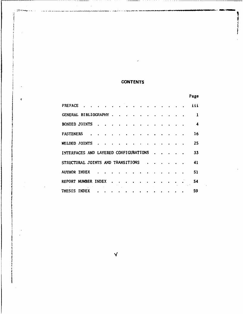
CONTENTS
Page
PREFACE ............. . . . . .. . ...... iii
GENERAL BIBLIOGRAPHY ............. . .. ... .1
BONDED JOINTS ........... . . . .. . .... .. .. 4
FASTENERS ................ . ........ . 16
WELDED JOINTS ............. . . .. . .... . .. 25
INTERFACES AND LAYERED CONFIGURATIONS . . . . . 33
STRUCTURAL JOINTS AND TRANSITIONS .. . . .... 41
AUTHOR INDEX ............ . . ...... . .. 51
REPORT NUMBER INDEX ......... .......... 54
THESIS INDEX ............ . ............ 59
iiV
4. Masubuchi, K., Simmons, F. B., and Munroe, R. E., "Analysis of ThermalStresses and Metal Movement During Welding." Battelle Memorial Institute,Columbus, Ohio. U. S. Army Missile Command Contract Report No. RSIC-820,July 1968. (AD 676 830)
A literature survey on thermal stresses during welding and buckling afterwelding is described. From the analyses, a~computer program was developedto calculate thermal stresses and resulting residual stresses due to amoving heat source and is included in the Appendix. Studies onthree-dimensional movement during welding of flat plate specimens aresumarized and interpreted. Results indicate that local metal movementduring welding is caused by bending moment and general metal movement iscaused by buckling.
5. Niranjan, V., "Bonded Joints: A Photoelastic Study." Toronto University,Institute for Aerospace Studies, Ontario. Research Report No. UTIAS-TN-138,July 1970.
The existing literature on bonded metal-to-metal joints on the stressdistributions in the adhesive layer is reviewed. The stress distributionis of significance for bonded joints designed to fail in the adhesive,either under static or fatigue loads. The stress distributions in themetal due to stress concentrations around the bonded joint are studied.These high stresses can be reduced in both the adhesive and the metal bychamfering the metal edges.
6. Pollard, B. and Cover, R. I., "Fatigue of Steel Weldments," Weld. J., 51(1972), S44s-SS4s.
A critical review of the literature published from 1938-1971 on thesubject of fatigue of steel weldments was made to determine the majorvariables which influence the fatigue behavior. The study showed that:(1) weld geometry is the most important factor in determining the fatigueproperties of a weld, (2) welding processes influence the fatigue strengthby producing welds of varying surface roughness and weld metal soundness,(3) residual stress only affects fatigue strength for alternating loads,(4) post weld treatments which produce compressive residual stresses mayincrease fatigue strength, (5) microstructure of the weld metal and theheat affected zone have a minor effect on fatigue strength. An extensivebibliography is included.
2
7. Sanders, W. W., Jr., "Fatigue Behavior of Aluminum Alloy Weldments,"Weld. Res. Counc. Bull., No. 171 (1972), 1-30.
A summary of an extensive literature search of both published andunpublished papers and reports on the fatigue behavior of Al alloy weldmentsis presented. The fatigue behavior of butt-welded and fillet-welded jointsis discussed and a "Summary of Fatigue Strength Data" for both configurationsare included in tabular form in the Appendix. The study shows that the mostcritical factor affecting fatigue strength is the weld reinforcement, withthe notch acuity at the toe of reinforcement being the single most importantconsideration. It is also shown that fatigue strength is reduced by lossof cross section due to internal defects and that in a good quality weld,the type of butt-weld joint does not seem to affect strength. A detailedbibliography is included.I
8. Schlothauer, J., "Bibliographic Data of German and Foreign Literature in theField of Adhesive-Bonded Metal Joints (1966-1968)." Deutsche Forschungsund Versuchsanstait fur Luftund Raumfahrt, Institut fur Flugzeugbau,Braunschweig, West Germany. Report No. DLR-MITT-69-10, July 1969.(N70-11083)
A bibliography containing available German ar' English references on thesubject of adhesive-bonded metal joints during the period 1966-1968.
9. Whitehurst, C. A. and Durkin, W. T., "A Study of the Thermal Conductance ofBolted Joints." Final Report. Louisiana State University, Division ofEngineering Research, Baton Rouge. National Aeronautics and SpaceAdministration Contract Report No. NASA-CR-102639, 1970. (N70-25816)
A review, evaluation, comparison, and utilization of current literatureregarding the phenomena of heat transfer across the interface ofdiscontinuous materials indicated the need for a simplified experimentaldesign oriented approach for predicting the thermal resistance of a boltedlap joint. Experimental work is compared with the current literature and aqualitative analysis is made of the present theories to demonstrate theinherent difficulties in combining the variables related to a theoreticallyapproximate solvable set of equations.
3
BONDED JOINTS
'O. Adams, R. D. and Peppiatt, N. A., "Effect of Poisson's Ratio Strains inAdherends on Stresses of an Tdealized Lap Joint," 3. Strain Anal.,8 (1973), 134-39.
Shear stresses in the adhesive layer and direct stresses in the adherendsacting at right angles to the direction of the applied load, which are causedby Poisson's ratio strains in the adherends, were investigated. The normalstresses along and across the adhereids are described by two simultaneoussecond-order partial-differential equations which were solved by both anapproximate analytical method and a finite difference technique and whichagreed closely. The adhesive shear stresses were obtained by differentiatingthese solutions. The transverse shear which occurs at the corners of the lanmaking them the most highly stressed parts of the adhesive, had a maximumvalue for metals % 1/3 of the maximum longitudinal shear stress. Bondingadherends of dissimilar stiffness produced greater stress concentrationthan similar adherends.
.1. Barker, R. M. and Hatt, F., "Analysis of Bonded Joints in VehicularStructures," AIAA J., 11 (1973), 1650-S4.
The behavior of arn adhesive joint bonding an advanced composite to ametallic substrate was evaluated by a linear elastic finite-element analysis.The adhesive layer is treatdd as a separate elastic medium of finite thick-ness to remove the stress singularity that exists when dissimilar materialsare joined. Results for both a single lap joint and a smoothly taperedjoint for two thickness of the adhesive layer are preseTited. In a lap jointthe load transfer mechanism is basically shear and high stresses occur inthe adhesive near the ends and the stresses increase as the thickness ofthe adhesive layer decreases. In a smoothly tapered joint, the load mechanismis a combination of shear and tension, peak shear stresses in the adhesiveare reduced and occur at only one end of the joint, thus it is a moreefficient joint. Recommendations for reducing stress concentrations andfor improved joint design are given.
See also: Barker, R. M. and Hatt, F., "Analysis of Bonded Joints inVehicular Structures," AIAA Paper 73-371, 1973.
4
12. Brock, L. M. and Achenbach, J. D., "Extension of an Interface Flaw underthe Influence of Transient Waves," tnt. J. Solids Strttctures, 9 (1973),S3-68.
The initiation of debonding which is caused by stress concentrationsthat are generated when a system of transient horizontally polarized shearwaves strikes the tip of an interface flaw, at an interface of two elasticsolids of different elastic constants and mass densities was examined. It
*• is shown that for a system of step-stress waves the zone of the interfaceyielding initially extei3s lineariy with time. The speed of the leadingedge of the zono of interface yielding is computed for various values ofthe parameters defining the materials and the system of waves. The time ofrupture and the interface stress ahead of the yield zone are presented byanalytical expressions.
13. Chang, D. J., "Stress Distribution in an Adhesive Joint." UnpublishedPh.D. dissertation, University of California, Loq Angeles, 1972.
Stress distribution in lap joints under cleavage and tension-shearloading was investigated or. the basis of classical two dimensional theoryof elasticity. The thickness of the .adhesive layer is assumed to be zero.The cleavage problem is reduced to a Fredholm integral equation of thesecond kind and the tension-shear problem to a pair of Fredholm integralequations of the second kind. Numerical results are presented for thedistribution of bond forces and for stress intensity factors at the edge ofthe bond covering practical material combinations and geometrical patterns.
14. Cherry, B. W. and Harrison, N. L., '"he Optimum Profile for a Lap Joint,"
J. Adhes., 2 (1970), 125-28.
Study was undertaken to attempt to show that with the correct choice ofthe profiles of the adherends, lap joints with uniform shear stress throuRh-out the joint can be manufactured. There are no shear stress concentrationsin the adhesive and maximum load carrying capacity of the adhesive isdeveloped. The calculation method is presented and practical applicaticnsare briefly discussed. The computations are based on elastic modulus andstrain! and are accordingly subject to limitations imposed by small-strainlinear elasticity theory.
DeLollis, N. J., "Theory of Adhesion-Mechanism of Bond Failure and Mechanismof Bond Improvement. Part 1 - Evolution and Present St•.cus of theTheories of Adhesion," Adhes. Age, 1;,, No. 12 (1968), 21-2S.
A mechanism of bond failure intended to correct practical and theoreticalknowledge of bond strengths and to supply reasons for failure and a practicalguide for developing optimum bond strength are proposed for structural-metal-adhesive designs. Resultt indicate that surface modifications improvebonds and weak boundary layers need not be significant factors in adhesion.Polymers studied include polye.thylene, silicone and polyurethane. Thepaper also briefly comments on the development and current status oftheories of adhesion.
DeVries, K. L., Williams, M. L., and Chang, M. D., "Adhesive Fracture of aLap Shear Joint," Exper. Mech., 14 (1974), 89-97.
A single-lap shear joint is analyzed by adhesive fracture which is com-pared on the basis of both maximum stress criteria and energy. Experimentaldata indicate the energy criteria yield more accurate results. In theanalysis stresses were introduced into an energy balance to determine theinitiation of adhesive fracture. From knowledge of the applied loads at theends of the test pieces, resulting internal loads upon the ends of the centerpart of the specimen near the tip were determined and from this the stresseswithin the central part of the lap area were calculated. The problem wn.formulated as one of plane strain consisting of two rectangular she:ts ofequal thickness, unit width, tab-end length, and central lenpth.
17. DeVries, K. L.. Williams, M. L., and Chang, M. D., "A Fracture MechanicsAnalysis of Adhesive Failure in a Single Lap Shear Joint." SESA Paper1990A, 1972.
The Goland-Reissner analysis was used to determine the stress distributionin a single lap shear joint and the initiation of adhesive fracture wasdetermined from an energy balance equation. Taking the deformation of jointsheets into account, the stress in the joint due to applied loads was deter-mined by the finite deflection theory of critically bent plates. The problemwas formulated as one in plane strain consisting of two rectangular sheetsof equal thickness and unit width. Contributions to the energy change withcrack length were calculated. The analysis is compared with a maximumstress criteria for a lap joint.
6
3. Dickson, J. N., Hsu, T., and McKenney, J. M., "Development of an Understand-ing of the Fatigue Phenomena of Bonded and Bolted Joints in AdvancedFilamentary Composite Materials. Volume 1. kaalysis Methods." FinalReport August 1970-April 1972. Lockheed-Georgia Company, LockheedAircraft Corporation, Marietta. Air Force Flight Dynamics LaboratoryContract Report No. AFFDL-TR-72-64-Vol. I, June 1972. (AD 750 132)
This report of the study is divided into three chapters: (1) ClosedForm Analysis Method, (2) Finite Element Analysis, (3) Photoelastic StressAnalysis. Emphasis was placed on the development of closed form analysisprocedures for bonded joints in laminated composites. A comprehensivelinear analysis method and associated computer program (BOXJO 1) wasdeveloped and the numerical results obtained were compared with finiteelement analyses, strain gage data, and photoelastic results. The programwas extended to include joints with ideally elastic-plastic adhesive stress-strain behavior. Finite element analyses used to evaluate the step lapbonded and bolted joints are presented and discussed. Photoelastic stressanalysis procedures are also described and discussed.
19. Erdogan, F. and Ratwani, M., "Stress Distribution in Bonded Joints,"J. Composite Mater., 5 (1971), 378-93.-
The problem of stress distribution in plates, one orthotropic and theother isotropic, bonded through stepped joints was analyzed. The adhesivelayer is regarded as a shear spring between the plates and load is appliedin the plane of the plates perpendicular to the joint line. Numericalexamples of resulting closed-form solution are given for: (1) a single-lapAl-epoxy-steel joint, (2) a multiply stepped Al-B epoxy joint, (3) asmoothly tapered Al-B epoxy joint. Bonding shear stress was greatest atthe end of a step. Results were relatively insensitive to boundary condi-tions when perpendicular to the joint line.
'0. Hamel, D. R., Korbacher, G. K., and Smith, D. M., "Fatigue StrengthOptimization of Bonded Joints," Trans. ASME, Ser. D: J. Basic Eng.,93 (1971), 649-56.
Bonded double strap joint specimens both with the conventional square(90") strap edge and with a 10° bevel on the strap edge were fatigue tested.The test data were plotted as S-N curves and compared with those of plainmetal specimens. Results indicated that the stress concentrations on thesquare strap edges were essentially lower than predicted theoretically andthe gain in fatigue strength due to bevelling of the edges is limited.
7
2i. Harrison, N. L. and Harrison, W. J., '"he Stresses in an Adhesive Layer,"J. Adhes., 3 (1972), 19S-212.
The finite element method is used for calculating the stresses near theends of a parallel-sided adhesive layer having aspect ratios of 10 orgreater and a Poisson's ratio of 0.49 or less. The material is treated aslinearly elastic and isotropic. The stress fields at distances > S thick-nesses from the free surface are uniform when the layer is subject to uniform,conditions of displacement at the adhering surfaces. The stresses in theuniform stress region determine the stress field throughout the layer. Whenthe stress field is expressed by functions of reduced coordinates of positionobtained by normalizing the Cartesian coordinates by the layer thickness,these functions are independent of the aspect ratio or the thickness foruniform boundary displacements. Shrinkage stresses and stresses in jointsunder both tension perpendicular to the plane of the adhesive layer andshear may be calculated by this method. Features of these stress fields aredescribed and presented in graphical contour plot form.
22. Hart-Smith, L. J., "Adhesive-Bonded Double-Lap Joints." Douglas AircraftCompany, Inc., McDonnell-Douglas Corporation, Long Beach, California.National Aeronautics and Space Administration Contract Report No.NASA-CR-112235, January 1973. (N74-1319S)
Analytical solutions that extend the elastic Volkersen solution andaccount, for adhesive plasticity, for the static load carrying capacity ofdouble-lap adhesive-bonded joints were derived. Results indicated that theinfluence of the adhesive on the maximum potential bond strength is depen-dent on the strain energy in shear per unit area of bond. Failures inducedby peel stresses at the joint ends were examined and this rode of failurewas found to be particularly important for composite adherends. The solu-tions may be used for design purposes.
23. Hart-Smith, L. J., "Adhesive-Bonded Single-Lap Joints." Douglas AircraftCompany, Inc., McDonnell-Douglas Corporation, Long Beach, Californ~ia.National Aeronautics and Space Administration Contract Report No.NASA-CR-112236, January 1973. (N74-13196)
Analytical solutions for the static loading carrying. capacity of single-lap bonded Joints were derived. For procedures and results see the previousentry in this bibliography.
S
24. Hart-Smith, L. J., "Adhesive Bonded Scarf and Stepped-Lap Joints."Douglas Aircraft Company, Inc., McDonnell-Douglas Corporation, Long Beach,California. National Aeronautics and Space Administration Contract ReportNo. NASA-CR-112237, January 1973. (N74-13197)
Continuum mechanics solutions for the static load-carrying capacity ofscarf and stepped-lap adhesive-bonded joints were derived. Adhesive plas-ticity and adherend stiffness imbalance and thermal mismatch were accountedfor. A simple algebraic formula which can be used as a close lower boundfor scarf joint solutions is presented. The critical adherend and adhesivestresses for each step in stepped-lap joints were computed using the pro-grams developed. Comparison of the scarf joint solutions and the double-lapjoint solutions showed marked differences in behavior. The potential bondshear strength of long overlaps continues to increase with infinitely longoverlaps on the scarf joints. The stepped-lap solution3 exhibit somecharacteristics of both scarf and double-lap joints. The program may beused to optimize the joint proportions.
2S Hart-Smith, L. J., "Non-Classical Adhesive-Bonded Joints in Practical Aero-space Construction." Douglas Aircraft Company, Inc., McDonnell-DouglasCorporation, Long Beach, California. National Aeronautics and SpaceAdministration Contract Report No. NASA-CR-112238, January 1973.(N74-12S55)
Solutions were derived for adhesive, joints with non-classical geometrieswith particular attention given to bonded doublers and to selective rein-forcement by unidirectional composites. Non-dimensional charts are presentedfor the efficiency limit imposed on the skin as a result of the eccentricityin the load path through the doubler. Relatively larger doublers were usedto minimize the effective eccentricity. Transfer stresses associated withselective reinforcement of metal structures by advanced composites areanalyzed. The adhesive joint analysis for shear flow in a multi-cell torquebox, adhesive plasticity, adherend stiffness and thermal imbalances arealso included. A simple analysis/design technique of solution in terms ofupper and lower bounds on an all-plastic adhesive analysis is introduced.
9
16. Hart-Smith, L. J., "Analysis and Design of Advanced Composite Bonded Joints."Final Report. Douglas Aircraft Company, Inc., McDonnell-Douglas Corpora-tion, Long Beach, California. National Aeronautics and Space Administra-tion Contract Report No. NASA-CR-2218, April 1974. (N74-20S64)
A summary of the work reported in the four previous entries in thisbibliography, on the analysis of various types of adhesive-bonded jointsis presented. Emphasis is placed on the non-dimensionalized solutions interms of the governing parameters to illustrate the overall joint behavioralphenomena in terms of the three characteristic failure modes - laminatedinduced, adhesive shear, and adhesive peel. Three detailed Appendixes areincluded, "Practical Design Configuration," "Scaling Effects in BondedJoints," and "Surface Preparation for Adhesive Bonding."
27. Jemian, W. A. and Wilcox, R. C., "Study of the Onset of Permanent Deformationin Structurally Bonded Joints." Final Report 19 November 1971-19 April1973. Auburn University, Department of Mechanical Engineering, Auburn,Alabama. U.S. Army Missile Command Contract Report, 1973. (AD 768 689)
The elastic sample compliance vs. crack length curve for lap-shearadhesive bonded samples was found to have a positive curvature and anincreasing slope as the crack length increased. The effects of variousparameters on this curve were determined. Results of finite element compu-tation showed that sample compliance is a linear function of adhesive thick-ness and sample stiffness depends directly upon overlap length, adherendthickness, adhesive and adherend moduli, and adhesive width. A standardfracture toughness testing procedure for lap-shear samples was outlined.
See also: Jemian, W. A. and Ventrice, M. B., "The Fracture Toughness ofAdhesive-Bonded Joints," J. Adhes., 1 (1969), 190-207.
28. Knauss, W. G.. "Fracture Mechanics and the Time Dependent Strength ofAdhesive Joints," J. Compos. Mater., 5 (1971), 176-92.
Fracture mechanics including the various modes by which fracture canprogress in joints formed with polymeric adhesives was investigated. In theanalysis the geometric and loading factors were separated from the strengthcharacteristics. Using the creep or relaxation behavior of the polymer andthe fracture energy of the bond interface or of the adhesive the time-dependence of the process in the absence of a corrosive atmosphere is dis-cussed. Analytical reasons and a criterion for the possible rate dependenceof the failure path location along different interfaces of adherends and theadhesive are given.
See also: Knauss, W. G., "Fracture Mechanics and the Time DependentStrength of Adhesive Joints." California Institute of Technology, Pasadena,California. National Aeronautics and Space Administration Contract ReportNo. NASA-CR-111761, September 1970. (N71-14080)
10
Lubkin, J. L. and Lewis, L. C., "Adhesive Shear Flow for an Axially-Loaded,Finite Stringer Bonded to an Infinite Sheet," Quart. J. Mech. Appl. Math.23 (1970), 521-33.
A mixed Volterra-Fredholm integral equation governing the adhesive shearflow is solved for a range of two dimensionless parameters. These para-meters describe the relative stiffness of the adhesive and sheet as well asthat of the adhesive and stringer. Results indicated uniform shear flow orlittle stress concentration when the adhesive is very flexible but very largestress concentrations are possible at one or both of the stringer ends ifthe adhesive layer is relatively thick.
Pahoja, M. ff., "Elastic Stress Analysis of an Adhesive Lap Joint Subjectedto Tension, Shear Force and Bending Moments." Unpublished Ph.D. disser-tation. University of Illinois, Department of Theoretical and AppliedMechanics, Urbana, 1972.
Stress analysis, treated as plane strain of a lap joint subjected togeneral loading - tension, shear force, and bending moments - is presented.Variation in the material properties and thickness of the two adherends isconsidered. The displacement field in the adhesive layer is expressed inseries form and the compatibility condition at the interface is used toexpress the displacement field in the adherends. The potential energy ofthe 'oint is calculated and minimized to obtain linear ordinary differentialequations and boundary conditions. Two specimens of a lap joint with 0.25"layer of a photoelastic plastic simulating adhesive were tested photoelas-tically with good agreement between theoretical and experimental results.
See also: Pahoja, M. H., "Stress Analysis of an Adhesive Lap JointSubjected to Tension, Shear Force and Bending Moments.,, University ofIllinois, Department of Theoretical and Applied Mechanics, Urbana. NavalAir Systems Command Contract Report No. UILU-ENG-72-6009, August 1972.(AD 753 469) 4
.• Peterson, J., "Toward Rational Design of Adhesive Joints," SAMPE Quart. 2, I
No. 3 (1971), 16-19.
An analysis to evaluate ordinary lapped adhesive joints without anextensive testing program is presented. The complex behavior of adhesivejoints can be reduced to elementary terms by consideration of memberstresses and strains. The analysis and comparison techniques for a jointtesting program can be used as a design tool to compare proposed joint con-figurations. The ideas are based on elementary strength of materialsconcepts.
11
'2. Renton, W. J. and Vinson, J. R., "The Analysis and Design of Composite MaterialBonded Joints under Static and Fatigue Loading." University of Delaware,Department of Mechanical and Aerospace Engineering, Newark. Air ForceOffice of Scientific Research Contract Report No. AFOSR-TR-73-1627,August 1973. (AD 766 932)
Extensive research was conducted to provide analytical methods and designmethodology for bonded joints in structures of laminated composite materialsunder static and fatigue loads. An analytical closed solution includingtransverse shear deformations and normal strain, adherend anisotropy, andadhesivc properties for adhesive joints and adherends was developed. Adigital computer program provides rapid design and analysis and an inclusiveparameter study provides trends and methodology. Shear and extensional stiff-ness and ultimate stresses of the adhesive in the joint configurations areprovided by the static tests developed. Fatigue tests were conducted forvarious geometries, loadings, and adherend materials. An extensive biblio-graphy is included.
-3. Rice, J. S., "Crack Stability of an Adhesive Layer," J. Franklin Inst., 294(1972), 1-11.
The stability of crack which is present in an adhesive layer that bondsan elastic plate to a rigid layer was investigated. The Wieghardt founda-tion was assumed as the model for the adhesive layer. The crack was loadedby internal pressure. Results are given for a relatively rigid and arelatively flexible plate. For brittle fracture crack theory in an elasticcontinuum there is an equivalence between the energy and stress intensitycriteria for fracture. This equivalence is not evident in the modelsproposed for the adhesive layer. For instance the energy criteria does notcontain the modulus of the adhesive layer unless higher order terms areincluded in the approximate model. Thus further analytical effort isrequired to arrive at an adequate model.
-14. Schijve, J., "Some Elementary Calculations on Secondary Bending in SimpleLap Joints." National Aerospace Laboratory, Amsterdam, Netherlands.Research Report No. NLR-TR-72036-U, March 1972. (N72-31911)
Formulas for calculating the permanent bending deformations of lapjoints resulting from tension loads are presented. Calculations indicatethat the effect of clamping conditions on secondary bending will generallybe small but a small amount of permanent bending deformation at the overlapwill have a significant effect on the secondary bending.
12
' u' .55. Terekhova, L. . and Skcryi, 1. A., "Stresses in Bonded Zoints of Thu-.3 • Cylindr ic--.,sz ahl2." Strtn th Mater., 4 1(973), l27)-74. Tns2t..,n
o ........ • .P 0 (19721,
Stresses ~~-'a the adhesive layeT qu-d the J;3"nted shells weredeoternined as a function of external loads, wnd the elasticity par-ameters ofthe adhesive and th shells. Calculations showed that the normal stressesin the bheils rev.-in ccnstant regardless of the modulus of elasticity forthe adhesive a, theo isngth of the joints and also that variation in thelength of the joint has no effect on the extent of the edge zones but themaximu- tangential stress in the adhesive layer chaniges slightly as thejoint length changes. Reducing the thickness of the shell by a factor oftwo increases the stress by SO.
36. Trantina, G. G., "Fracture Mechamics Approach to Adhesive Joints,"i. Conposite Mater., 6 (1972), 192-207.
A finite element stress analysis for a slant edge-cracked plate furnishedthe opening and shear mode stress intensity factors over a wide range ofslant angles and crae-k lengths in a study of crack extension in an adhesivesystem under combined mode loading. By varying the angle between the adhe-sive layer and the load line in a single-edge-notched specimen, combinedmode crack extension was observed and combined mode fracture toughness valueswere then determineo. The effect of the locatieon of the crack tip-bondLcenter or interface) is also discussed.
See also: Trantina, G. G., "Fracture Mechanics Approach tu AdhesiveJoints.' University of Illinois, Department of Theoretical and AppliedMechanics, Urbana. Naval Air Systems Command Contract Report No.IUILU-ENG-71-60014, August 1971. (AD 731 992)
37. Wah, T., "Stress Distribution in a Bonded Anisotropic Lap Joint," Trans.ASME, Set. H: J. Zng. Mater. Tech., 95 (1973), 174-81.
A theoretical analysis of a bonded lap joint in the elastic range ispresented. It is assumed that: the adhesive is isotropic, the joint issufficiently uide to be in a plane strain state, and bending is sy,.metrical.To simplify the problem it is supposed that the laminated adherenrd aresymmetrical so that the bending and stretching terms are uncoupled. Nwner-ical results are given and based on these a simplification of the analysisis suggested.
,. '1. 3
8 Westmann, R. A., "An Elementary Model for Yielding Slip in Adhesive Joints."Institut fuer Festkoerpermechanik, Freiburg, West Germany. ResearchReport No. WB-l/73, January 1973.
Stress and displacement analyses for an adhesive joint modeled by twoelastic half planes connected by an infinitely thin bond line of finitelength, were conducted and results are presented. It was assumed that theconnection transfers a normal and shear force as well as a resultant moment,Yielding and slip along the bond line accounted for inelasticity in theadhesive. The Barenblatt-Dugdale approach and singular integral equationswere used to obtain the pertinent stress and displacement components alongthe bond line. Failure of the joint was analytically predicted by employ-ing the concept of a critical COD or a critical plastic zone size. Resultsare compared with predictions made by the brittle fracture theory.
39. Westmann, R. A., "A Structural Model in Adhesive Mechanics." Institut fuerFestkoerpermechanik, Freiburg, West Germany. Research Report No.WB-6/73, May 1973.
A preliminary structural model for the approximate stress analysis ofadhesive joints is presented. A reinforced plate theory which accounts forboth shearing and plate thickness deformations was used for the model. Adouble cantilever beam test specimen was considered to assess the accuracyof the model. Expressions for the bond line tractions and crack tip stressintensity factors are presented and show good agreement with values obtainedby other methods for a range of geometric parameters.
40. Williams, M. L., "Cohesive-Adhesive Fracture in a Pressurized Double Blister,"
J. Adhes., 5 (1973), 81-87.
This is an approximate analysis of a three-layer medium which estimatesthe critical applied pressure and preferred locus of fracture initiation as
a function of geometrical and mechanical properties.
41. Williams, M. L., "The Fracture Threshold for an Adhesive Interlayer,"J. Appl. Polym. Sci., 14 (1970), 1121-26.
An energy balance criterion for a continuum mechanics model of adhesivefailure in a pressurized blister at the interface of an elastic materialand a rigid substrate was extended to include an additional elastic inter-layer between them. The energy calculations were simplified by usinglinear elastic beam theory, a Winkler-type elastic foundation (neglectingshear deformation and shear strain energy) was used, and most importantseparation along the line between the plate and adhesive layer was assumed.Results showed that the tensile modulus-to-thickness ratio of the adhesivelayer and the adhesive fracture energy of separation of the respectivematerials were the most critical design parameters.
14
iI
42. Iooley, G. R. and Carver, D. R., "Stress Concentration Factors for BondedLap Joints," J. Aircraft, 8 (1971), 817-20.
Stress analysis of a bonded, single lap joint by finite element methodwas completed and a modified version of the Nilson stress analysis programwas used for the case of plane stress. Stresses occurring in the adhesivelayer, and stress concentrations as a function of geometric and materialparamete. arc presenteu. Poissonis ratio was taken as 0.3 for each layerand a ratio of adherend and adhesive elastic modulus was varied from 0.1to 1000. Lap length and joint geometry were treated as independent variablesand overall length-to-thickness ratio was arbitrarily taker as 100. Theanalysis is based on linear displacement function within each element.
is
i ~ ~~~~ ........... . . ..
FASTENERS
•3. Birger, I. A., et al., "The Limiting Plastic Condition and Shear of Threads,"Russ. Eng. J., 48, No. 3 (1968), 35-40. Translation _,f Vestn. Mashinostr.,48, No. 3 (1968), 32.
Fine threads are preferred in some machine designs because the largethread diameter to pitch ratio in which the cross-sectional area of the boltis greater results in a stronger bolt. The shear strength with a high pitchratio can be increased when the engagement length, as the nut height, isincreased. The maximum number of threads carrying the load characterize thelimiting engagement strength when the threads are beginning to yieldplastically. A mathematical theory on the subject is presented and anintegral equation which is solvable with the aid of successive approximationswas developed. The limiting engagement strength is dependent on the ratiobetween the mechanical properties of the bolt and nut materials and thepitch and diameter of the thread. Joint strength can also be increased byusing a coarse thread and a buttress-type thread with a 0* angle to reducelateral deformation.
44. Bradley, T. L., Lardner, T. J., and Mikic, B. B., "Bolted Joint InterfacePressure for Thermal Contact Resistance," Trans. ASME, Ser. E: J. Appl.Mech, 38 (1971), 542-45.
As part of a study on thermal joint conductance, a three-dimensionalphotoelastic analysis using the stress freezing technique was used topredict the interface pressure - a factor needed to calculate the thermalcontact resistance across a bolted joint. Nine bolted joints wereinvestigated using smooth flat plates of photoelastic material and equalthickness. The integration of the interface pressure distribution over thearea of contact was within 10% of the applied load for all experimentalresults and usually was within 5%.
;S. Bragin, D. Ya., Shkanov, I. N., and Vasil'yev, G. V., "Problem ofCalculating Bolted Joints under Stress Relaxation and Creep ConditionsDuring Vibrations." Foreign Technology Division, Wright-Patterson AirForce Base, Ohio. Report No. FTD-HT-23-0276-73, May 1973. (AD 761 455)
Existing methods for calculating tight bolted joints for stressrelaxation are based on equations corresponding to a particular theory ofcreep which gives the most accurate quantitative description of creep andstress relaxation of fastening materials in the specific conditionsinvestigated. The equations are described and evaluated.
16
46. Brombolich, L. J., "Elastic-Plastic Analysis of Stresses Near Fastener Holes.'AIAA Paper 73-252, 1973.
A finite element analysis method of determining the stresses near fastenerholes is presented. Plasticity, load sequence effects, fastener interference,and the contact problem creat.i by the-inability to develop tensile radialstresses across the fastener plate boundary are considered. Severalapplications are presented and stress distributions in plates containingfasteners which are subject to cyclic, uniaxial, in-plane loading conditionsare discussed.
47. Chan, S. K. and Tuba, I. S., "A Finite Element Method for Contact Problemsof Solid Bodies - Part I. Theory and Validation," Int. J. Mech Sci., 13(1971), 615-25.
A modified finite element method for solving problems of elastic bodiesin contact is described. The method is general and could be extended tosolve problems in other classes of structures. The sample results showedgood agreement with corresponding exact solutions.
48. Chan, S. K. and Tuba, I. S., "A Finite Element Method for Contact Problemsof Solid Bodies - Part II. Application to Turbine Blade Fastenings,"Int. J. Mech. Sci., 13 (1971), 627-39.
The effects of clearances and frictional forces on blade root fasteningstress distributions were investigated by the finite element method and thecomputations were compared with the available photoelastic results.
49. Cruse, T. A., Konish, H. J., Jr., and Waszczak, J. P., "Strength Analysesfor Design with Composite Materials Using Metals Technology."Proceedings of the Colloquium on Structural Reliability, The Impact ofAdvanced Materials on Engineering Design, Pittsburgh, Pa., 9-12 October1972. Edited by J. L. Swedlow, T. A. Cruse, and J. C. Halpin.Pittsburgh: Carnegie-Mellon University (1972), 222-36.
Using a simple model obtained from lamination theory and restricted tomidplane symmetric laminates subject to in-plane loading, the effects ofsharp cracks and loaded holes on the strength of composite structures wereinvestigated. The strengths in bolted joints in boron and graphite epoxyplates were evaluated and the fracture of advanced fiber composites waspredicted. Results indicate that in order to use linear elastic fracturemechanics to characterize composites factors such as the lower bound oncrack length and the material dependence on finite dimension correctionfactors must be taken into account.
17
"7). Erisman, R. J., "How Dimensionless-Parameter Technique Aids in TheoreticalAnalysis of Bolted Joint Problems," Fasteners, 23, No. 4 (1968), 9-11.
Two equations are presented graphically in a form which gives mostparameters necessary for theoretical solutions to bolting problems. Designparameters include torque distribution, torque-tension ratios, friction-size/torque-tension relationships, and simplifications obtained in stressrelationships through dimensionless parameters.
$1. Fontenot, J. E., Jr., "The Thermal Conductance of Bolted Joints."Unpublished Ph.D. dissertation, Louisiana State University andAgricultural and Mechanical College, 1968.
Subsequent to a literature review, a comprehensive experimental andanalytical program was conducted to attempt to eliminate technological gaps.The survey indicated, for instance, development of a completely analyticalmethod was hampered by each of: (1) experimental data for stressdistributions under boltheads, (2) an adequate method for interface stressesin regions of apparent contact at bolted layers, (3) a theoretical methodfor predicting interface gaps under prescribed stresses. Accordingly thesedeficiencies were treated and a practical method of determining theinterface thermal conductance of a bolted joint, using a minimum of designinformation, was formulated. Computed values of thermal conductance wereused in a finite-difference heat transfer analysis of steady-statetemperature gradients across aluminum-and stainless steel joints in air andvacuum. Analysis was confirmed via experiments.
:2. Fried, E., "A Joint Heat Transfer Data Critical Study and Design Guidelines."General Electric Corporation, Space Systems Organization, Philadelphia,Pa. National Aeronautics and Space Administration Contract Report No.NASA-CR-119933, June 1971. (N71-38345)
Information on the prediction of bolted joint heat transfer was reviewedand guidelines and procedures for design engineers to predict withinreasonable limits this joint heat transfer for spacecraft applications arerecommended. Tables and graphs on bolted joints and related data arepresented and a glossary of terms is provided. Since analytical methods arenot completely developed to provide reliable predictions, empirical approacheswere used exclusively.
I
53. Gould, H. H. and Mikic, B. B., "Areas of Contact and Pressure Distributionin Bolted Joints." Massachusetts Institute of Technology, EngineeringProjects Laboratory, Cambridge, Mass. National Aeronautics and SpaceAdministration Contract Report No. NASA-CR-l02866, June 1970. (N70-41982)
Finite element method was used to compute the pressure distributions inthe contact zones and the radii at which flat and smooth asymmetric linearelastic plates of several thicknesses will separate. The radii ofseparation was also measured by two methods; one employed autoradiographictechniques and the other measured the polished area around the bolt hole ofthe plate caused by sliding under load in the contact zone. The resultsobtained are in agreement with experimental data and yield smaller zones ofcontact than indicated in the literature. The analysis method and thecomputer programs and instructions for their use are included.
54. Hamada, K., Ukaji, H., and Hayashi, T., "Stress Analysis of Bolted Flangesfor Pressure Vessels." Proceedings of the First International Conferenceon Pressure Vessel Technology, Delft, Netherlands, 29 September-2 October 1969. New York: American Society of Mechanical Engineers(1970), S13-27.
A design method, in accordance with the ASME code, of flanged joints for'pressure vessels under bolting and internal pressure loads was investigated.A new digital computer program for the analysis of stresses and distortionin flanges that can provide accurate evaluation of a tapered hub section,interaction with mating flange connected by bolts, and bending stress andstiffness of bolts due to flange rotation is described.
55. Harris, H. G., Ojalvo, I. U., and Hooson, R. E., "Stress and DeflectionAnalysis of Mechanically Fastened Joints." Grumman Aerospace Corporation,Bethpage, N. Y. Air Force Flight Dynamics Laboratory Contract ReportNo. AFFDL-TR-70-49, May 1970. (AD 709 221)
A set of stacked parallel plates which transfer planar loads amongthemselves by means of transverse fasteners were used in an analyticalmodel for predicting both linear and nonlinear stresses and deformation inmechanically fastened joints. The plates were treated by finite elementmethods of matrix structural analysis in which each element was assumed tobe in plane stress for both elastic and plastic states. The techniqueswere applied to several problems: (1) load-deflection behavior of single-fastener joints, (2) combined elastic-plastic behavior of plates withunloaded holes, (3) residual stress distribution in plates with squeezerivets, (4) effect of fastener bending and shear deformation on the bearingstress distribution between the fastener and plate, (5) prediction offatigue life of typical mechanically fastened joints.
19
56. Markovets, M. P., "Graphic-Analytic Method of Calculating the Time to Failureof Bolts under Stress Relaxation Conditions," Therm. Eng., 17, No. 6(1970), 77-79. Translation of Teploenergetika, 17, No. 6 (1970), 52-.4.
A method based on a comparison of stress relaxation and long-time strengthSdiagrams. With stepwlse long-term loading conditions, the reduction ofeffective cross section can be calculated by determining the times to failurefor corresponding loading from the long-time diagram. Time to failure iscalculated as the time when the reduction of the effective cross sectionreaches a critical value - an example is given.
57. Menker, C. M., "Influence of Bolt Loading on Deformation of Pressure VesselFlanges." Proceedings of the First International Conference on PressureVessel Technology, Delft, Netherlands, 29 September-2 October 1969.New York: American Society of Mechanical Engineers (1970), 143-53,
The question of whether rotationally symmetric deformations will occur inflanges of pressure vessels with both rotationally symmetric loading andgeometry was investigated. The effect of periodic loading - equal boltloads - on the deformation of a rotationally symmetric integral flange wasstudied. Results show that the periodic deformation of the flange can beneglected when compared with rotationally symmetric deformation.
58. Milov, A. B., "Calculation of the Contact Stiffness of Cylindrical Joints."Strength Mater., 5, No. 1 (1973), 74-77. Translation of Probl. Proch.,No. 1 (1973), 70-72.
Plane contact problems where the contact zone has considerable dimensionsare treated. Pressure distributions in the contact region are approximatedwith a cosine form. Comparison of the resulting expression for relativedeflection and contact angles is made for the two- and three-dimensionalelasticity solutions. These are problems of axisymmetrical loading of athin disc (plane problem) and compression of a solid cylinder by a "bandload" (three-dimensional problem). On the basis of the comparison acorrection coefficient accounting for the width of the loaded portion andthe effect of three dimensions, is presented.
20
I~
59. Oplinger, D. W. and Gandhi, K. R., "Stresses in Mechanically FastenedOrthotropic Laminates." Paper presented at the 2d Conference on FibrousComposites in Flight Vehicle Design, Dayton, Ohio, 21-24 May 1974.(Proceedings to be published as an Air Force Flight Dynamics LaboratoryReport)
Analytical results for elastic response and failure of mechanicallyfastened orthotropic plates containing both single and multiple fastenerzonfigurations are presented. The least squares collocation method inconjunction with a complex variables formulation for the two-dimensionalelastic response was used. An interactive approach was used to determinethe contact length, a nonlinear aspect of the problem. The effects oforthotropy and plate geometry as well as those of certain fastenerinteractions which may be present in rows of fasteners were considered. Thejoint configurations investigated were single pin, periodic array in finiterectangular plates, and an isolated pin in an infinite plate which corresporl sto the case of pins widely spaced and well removed from neighboringboundaries. Results showed the occurrence of an optimum value of s/D of2.0, which corresponds to a minimum in the ratio peak net section tensionto applied stress.
60. Popper, J. B., "A New Method of Screw Strength Calculation," Trans. ASME,Ser. B: J. Eng. Ind., 93 (1971), 1233-38.
Method for calculating the strength of screw fastenings, consideringthread geometry, combined tensile and shear stresses and uncertainty of theexact values of friction coefficient, is presented. The calculated strengt-is smaller but more realistic. Safety factors as low as 1.2 can be used.Equations derived indicate screw strength can be increased and even doubledby the use of preloading washers and by turning the screw back afterinitial tightening.
61. Potelezhko, V. P. and Solonets, B. P., "Investigation of Tightness ofRiveted Joints with Cover Plates," Strength. Mater., 3 (1971), 111-15.Translation of Probl. Proch., No. 1 (1971), 114-17.
The nature of the distribution of the unit pressure between the mainelements and the cover plates of a multiple riveted joint was investigatedusing elastic theory. Graphs are provided which permit determination ofrivet distance as a function of rivet-head diameter, and cover and mainplate thickness in order to maintain a given relative unit pressure ratioat the midpoint of the rivet spacing. Knowledge of this stress level isi.portant since joint tightness is essentially controlled by the magnitudeof this pressure.
21
62. Potelezhko, V. P. and Solonets, B. P., '"rightness of Riveted Joints,"Russ. Eng. J., 51 No. 8 (1971), 36-38. Translation of Vestn. Mashinostr.,SI, No. 8 (1971), 30-32.
The tightness of riveted joints was determined by the minimal pressure,"Iqn - at the mid-point in the shortest distance between rivets. The valueofqmi n is dependent on the diameter of the rivet head, "D", the thicknessof the joint components "h" and the rivet pitch, "t". The pressure and itsdistribution are not dependent on the materials that make the jointcomponents.
63. Puppo, A. H. and Haener, J. A., "Application of Micromechanics to Jointsand Cutouts." Whittaker Corporation, San Diego, Calif. U.S. ArmyAviation Laboratories Contract Report No. USAAVLABS-TR-69-25, April 1969.(AD 688 168)
Analytical and experimental methods were used to study the stressdistribution in loop and bolt joints in composite materials. The numericaltechnique to evaluate the stresses and displacements is described and simpleformulas for computing the stresses at critical regions were developed.Photoelastic technique was used for stress distribution tests. Failurelocation and ultimate loads for several composite joints are shown.
64. Roca, R. T. and Mikic, B. B., "Thermal Conductance in a Bolted Joint."AIAA Paper 72-282, 1972.
The effect of roughness at the contact region of a bolted joint on boththe large scale constriction, and the small scale constriction, which isinfluenced by the magnitude of the local pressure is shown analytically.The sum of the two constriction effects, the total resistance, may increaseor decrease with changing resistance. Examples are given where an optimumroughness minimizes total joint resistance.
65. Wade, L. V. and Stahl, P. A., "Effects of Specimen Radius on the StressState Near a Roof Bolt Anchor: A Finite Element Determination." Bureauof Mines, Washington, D. C. Research Report No. BuMines-RI-7748, June 1973.(PB 221 863)
The effects of the rock specimen size used in testing anchor performancewere determined. Results showed that the stress state at the anchoragehorizon varied significantly between o'd. cores and cores of larger d. butnot when the specimen d. was > 12". I e anchor horizon stress field was notsignificantly altered by the noninclus,on of bearing-plate stress field.The stress state was not significantly changed by the inclusion andsubsequent exclusion of the effects of gravity. More realistic mathematicalmodeling is possible through the use of three-dimensional finite elements.
22
16. Waszczalf,,J.P and Cruse, T. A., "FiucMode and Strength P~redictions ofAniotrpi Bot Barng pecmas." j Coapaf.it -ae. 17) 4211-25.
The problemt of a single bolt -in an orthotropic lamirnate of crosspliedconfiguration was treated by a finite element computer code. A cosinedistribution of normal stress acting on half of the hole surface was usedto simulate the bolt loading and friction effects were neglected. Threeanisotropic failure criterion: maximim stress, r~aximum strain anddistortional energy were evaluated. The distort:.onal energy criterion wasfound to be reliable and conservative in predictin.g loolt failure loads insimple bolt bearing tests.
67. Waszczak, J. P. and Crujse, T. A., "A Synthesis Procedure for MechanicallyFastened Joints in Advanced Composite Materials.,, Final ReportNovember 1971-August 1973. Carnegie-Mellon University, MechanicalEngineering Department, Pittsburgh, Pa. Air Force Materials LaboratoryContract Report No. AFMt-TR-73-145, Vol. 11, September 1973. CAD 771 795)
A general optimization procedure using simpli-fied results of the author'searie stdis rpoted in the Drevious entry of this bibliography. Based
on lamainate failure modes and minimum weight constraint, an optimizationrn-ýthodology as well as resulting joint configurations are described.
68. White, D. i. and Enderby, L. R., "Finite Element Stress Analysis of aWon-LiLnear Problem: A Connecting-Rod Eye Loaded by Means o~f a Pin,"J. Strain Anal., 5 (1970), 41-48.
A stress analysis method using existing linear elastic finite elementcomputer programs is given for a non-linear problem - a connecting rodunder a tensile load. The connecting rod eye wus idcali~ed as a plaiiestress problem and special overlapping elements were introduced to connectt .he eye and the pin at radially adjacent ncodes. These elements wereassigned stiffnesses which were changed in a prescribed manner after each rununtil compatability of forces and displacements, allowing for initialclearances, was obtained at each connecting point. Eight runs, wererequired to achieve correct displacements but results indicated that thecircumferential stresses did not change appreciably after the first few runs.There was good agreement between the calculated results and laborator-y testmeasurements made with electrical-resistance strain gauges.
2 3
69. Wilkinson, T. L., "Analysis of Nailed Joints with Dissiizilar M4embers,"Proc. ASCE, J. Struct. Div., 98, No. S-79 (1972), 21OOS-l3.
A theoretical model of analysis, based on the theory of beams on elasticfoundations, was derived in order to predict the slope of the load-slipcurve of two-smeber nailed wood joints under lateral load. The -11-tiodallows analysis of joints in which the properties and thic'.ýiness of themembers are dissimilar. The different sizes end "t~terials of tChe n-ails aswell as the different species of wood are accounted for by' incorporatin-g afoundation modulus determined from an cl.istic bearing constanit proportionalto the wood density. Elastic bearing constant values for various types ofjoints and experimental verification of the theoretical expressionsare presented.
70. Wilkinsol,. 1'. L.., "Theore'ical Lateral Resistance of Nailed Joints.,"P-,,c. ASICE, J. Struct. Div., 97, No. STS (1971), 1381-98.
T"he behavior of beams on elastic foundations was studied by a theoreticalanalysis and results compared with test data for deflection and proportional,limit stresses of nailed joints under lateral load. A simple theoreticalequation was derived whidý relates single shear load with joint slip foralaterally loaded smooth round nail in a two-membler wood joint. The elasticbearing constant, experimentally determined. was found to bo linearly Krelated to iverage specific gravity of the wood species.
71. Yip, F. C., "Theory of Thermal Contact Resistance in Vacuum with anApplication to Bolted Joints." AIAA Paper 72-281, 1972.
A new expression for thermal contact resistance in vacuuim for roughsurfaces of normal height distribution was derived and is applicable forboth uniform and nonunl1--.m stress distribution~s which may occu-r at theinterface. The effect Of two rLonuniform stress distributions on themic--rocotact resistance of a bolted joint was examined. Analytcical resultsshow little difference between uniform and nanunifoiAn stress distributions.A simplified solution which governs the thermal and mechanical propertiesand the metrology Of surfaces is proposed.
-4
WELDED JOINTS
72. Ankdrews, J. B., Arita, M., and lýasubuchi, K., "Analysis of Thermal Stressand Metal Movement During Welding." Massachusetts Institute ofTechnology, Department of Naval Architecture and Marine -Engineering,Cambridge, Mass. National Aeronautics and Space Administration ContractReport No. NASA-CR-6l35i, December 1970. (N71-26i43)
An analytical system for calculating thermal stresses during welding andthe associated residual stresses !!r outlinzwd. ilongitudinal stresses, thoseparallel to the weld line were analyzed. Using the computer progrardeveloped, the effect of material proper-ties anvJ welding pzara'neters on thethornmal stresses and metal movement were evaluated. Steel, Al, Nb, and Tamaterials were studied and a detailed analysis was made of the effects ofwelding parameters on thermal stresses during bead-on-plate welding of2219-0 Al. Tiemperature and strain changes were recorded and compared wihthose calculated with the computer program.
fi
73. Burmistrov, V. P., "Assessing the Effects of the Design and TechnologicalParameters on the Reliability of Joints in Components Made of PlateMetal," Automat. Weld., 24, No. 8 (1971'; 39-41. Tranislation ofAvt. Svarka, No. 8 (1971)-,39-40.The effects of batc-h-to-batch variations in mean weld strengths and
geometry of weld joints was assessed by simple reliability equations inconjunction with an experimental program. The mathematical model was basedon normal probability distributions and a first order linear expansion of aLagrange function of joint loads and spot weld strengths.
74. Butler, L. J., Pal, S., and Kulak, G. L., "Eccentrically L~oaded WeldedConnections." Proc. Am~er. Soc. Civil EgJ. Struct. Div., 98, No. STS(1972), 989-1005.
An. analytical method, using the true load-deformation response of thewelds rather than some idealized one, to predict the ultim,.ate load of eccen-trical ly loaded weld groups was developed. Thirteen full-size specimenswere tested to verify the validity of the method. By using the more accu-rate predictions presented, the safety factor can be brought into line withthat of other structural components and can be established at a constantvalue for all connections of this type.
3-2
I I-i.-- - IIII-III---I--I---- --- I--I---- --.- --
75. Byers, N. R. and Schultz, R. F., "Analysis of a Stub End by the FiniteElement Method," Weld. J., S1 (1972), 31s-35s.
Finite element method was used to analyze the axi-symmetric stressproblems in the stub end portion of a bolted flange pipe connection. Threedifferent stub end configurations with various material properties of theindividual elements as required to represent the weld material or the parentmetal were tested. The stresses and coordinates of the centroid for eachelement comprised the output of the computer program used. The resultingstresses were plotted as contours on the stub end with convergence of stressvalues observed as the element size was decreased. Results indicated therewere no significant differences (< 5%). A typical contour stress plot isshown.
76. Chihoski, R. A., "The Character of Stress Fields Around a Weld Arc Movingon Aluminum Sheet,'' Weld. J., 51 (1972), 9s-18s.
Using the solutions for temperature rise at points around a moving heatsource, isotherms were taken for representative configurations around amoving gas tungsten welding arc. Neglecting shear stresses, the isothermalstress distributions in approximating strips were calculated. The shapeand intensity of the tension and compression stresses which are approximatefor conditions around the heat source are described for two weld speeds.The elementary analysis provides a systematic explanation of common weldingexperiences such as cracks, shrinkage, part distortion, sudden changes incurrent demands and unexpected responses to welding gaps. Several experi-ments demonstrate qualitative correctness of the model.
77. Finnie, L. and Vaidyanathan, S., "Stress Analysis of Welded Joints withParticular Reference to Circumferential Welds in Cylinders." Universityof California, College of Engineering, Berkeley. Research Report No.UCRL-13569, 1972.
The differences in the residual stress distribution produced by a circum-ferential weld between axisymmetrical shells and a butt weld between twoflat plates are pointed out. The state of stress in the shells may beestimated from that in the plates. Experimental results on electron beamwelded Al parts obtained for a full penetration, single pass weld with novariation of alloy content across the weld showed good agreement with thepredictions. It is also shown that multipass welds, partial penetrationwelds, and welds with a filler metal different from the base metal can allbe taken into account using this approach. Two types of simple fracturetests - a small specimen constrained by a rigid fixture and a largerspecimen completely unconstrained during arc discharge - were used to showthat the extent of crack propagation depends on the fracture properties ofthe material. Experimental data are given to illustrate both types oftests.
26
;_._ • _ _.. .. _ _
78. Ginigor'ev, L. Ia., 'Thermal Stresses in a Cylineer in the Case of anArbitrary Temperature Distribution AlonR Tts Axis." Sov. Ar .Mech.. 8,No. 3 (1972), to be published. Translation of Pirkl. ekh., 8, No. 3(1972), 42-46.
Assuming a constant temperature across the cylinder, the thermoelasticproblem of the stresses in a cylinder was solved for an arbitrary linearexpansion coefficient. The problem of stress distribution in a welded butt• •..joint between two cylinders having different lin-ear expansion coefficientsis solved as an example.
79. Huber, R. A., Braidway, D., Wiedemann, C. ,M., and Turner, P. W., "ComputerPrograms for Calculating Peak Temperature Distribution in Welding."Union Carbide Corporation, Oak Ridge, Tenn. Atomic Energy CommissionContract Report No. Y-1627, October 1968.
Computer programs for solving the heat-transfer equations relating tor.noving heat sources zýncountered in welding operations were developed. Thetypes of problems solved for the engineer and designer are: (1) thermalmapping to determine the "temperature hill" enveloping the welding heatsource on a semi-infinite plate, (2) determining peak temperatures at some"distance from the centerline or from the bond line, (3) determining thesurface peak temperature at the edge of a plate paral]el to the weld,(4) determining the peak temperature on the bottom side of plates havingpartial-penetration welds.
80. Kozlov, V. S. and Savitskii, A. A., "Determining the Depth of PenetrationWelding by Radiation Methods," Weld. Prod., 18, No. 11 (1971), 10-12.Translation of Svar. Proizvod., No. 11 (1971), 7-8.
An infrared pyrometer wa@s used to continuously determine weld depths.The procedure relies on the fact that the penetration depth during weldingis related to the vertical temperature distribution in the material. Underthe assumption of temperature independent thermophysical constants, andusing the three-dimensional Fourier heat conduction equation, the relationbetween penetration depth and general temperature distribution can bederived.
81, Ma"unenko, V. I., Velikoivanenko, E. A., -.. • Shekera, V. M., "Kinetics of Athe Stres.sed and Strained State in Sheet Aetal WMen Cracks are Welded Up,"Automat. Weld., No. 2 (1970), 36-40. Tr&msiation of Avt. Svarka, No. 2(1970), 36-40.
Kinetic changes in the stress, strain, and temperature distributionsaround cracks in metal plates during welding-up operations are discussed interms of theoretical calculations and experiszntal tests. The develoumentof elast-_-p!astic d&forTations and stress states in the heat affected zone
* when cracks in shýet natal are welded were traceqd by calculation for botha rigid system and a system with free edges. Compressive strains tend todevelop in the region imaediately surrounding the weld. In the coolingstage transverse welds change less rapidly with time than longitudinalstrains.
82. Masubuchi, K. and Ich, N. T., "Computer Analysis of Degree of Constraint ofPractical Butt Joints," Weld. J., 49 (1970), 166s-76s.
Various finite element moreies were employed to determine appropriatemethods to represent constraints typical of joints. The degree of con-straint was simulated by various plate configurations containing straightslits, slits with circular ends, H-type and other slits. A constant strainelement Aith relatively coarse gridding (105 nodes) was succcssful asdcmonstrrated by some confi-Minr experiments.
83. Mehrotra, B. L., "Matrix Analysis of W'elded Tubular Joints." UnpublishedPh.D. dissertation, McGill University, 1970.
A nuLmerical procedure based on the finite element in the form of ageneral purpose computer program to analyze stresses, strains, and defornm- k.tions of any arbitrarily thin-walled three-dimensional structure havingrandom static loadings, boundary conditions, and variable wall thicknesses,including stiffening was developed and used to analyze joints betweenrectangular tubular members. Semi-empirical formulas were developed forpredicting joint hiodulus as well as stresses and deflections in theconnected branches for symmetrically welded full-width connections betweenrectangular tubes and a computer program is presented. A two-dimensionalplane-stress substitute model is suggested to show the joint behavior of itscounterpart three-dimensional full-width connection in the elastic rangeand then extended to the inelastic range. Full scale experiments were con-ducted iunder different loading and boundary conditions to verify the results.
)
2 28
I
%, 'ehrotra, B. L. apd Govil , K. K, "Shear Lag Antlliyis of Rectangular Full-width 'rube Junctions, " Proc. ASCE, 3. Strucýt. Cli-. 98, No. STI(17)
A shear lag analysis is suggested for analytically dettrmining the Jointstiffness of welded junctions between rectangular hollow tubes. A completestress anallysis of tynical connections is giver~ along with numerical valuesof joi-nt stiffness for most full width connections of sizes included in the1967 AIISC '14anual. Results were verified both experimentally ana by a three-dimensional finite element solution. Semi-expirical equations for eva-laa-ting the joint Stiffness are given. Curves showing the --pecial behavior ofthese Joints in load transfer to main menber are presented.
8S. Nagarajarao, N. R., Marek, P., and Tiall, L., "Welded Hybrid Steel Columns,"VWeld. I.., SI (1972), 462s-72s.
The analysis and results of an investigation to determine the strength ofhybrid steel columns composed cf 'low strength .iebs welded to high strengthflanges are presented. included in theoretical analysis were the tangentmodulus and ultimate load, the mechanical properties of the materials, theactual residual stress distribution, and local buckling. Five hylbrid shapesf.1abricated from flame-cut or universal mill plates we-re tested. Tensionspecirsan coupon, residual stress measurements, stub column tests, and pinnled-end column tests with a slenderness ratio of 65 were conducted. Resultsshowed that column strength of hybrid shapes can be predicted from the actualstress distribution by theoretical analysis.
86. Nickell, R. E. and Hibbitt, H. D., "Thermal and Mechanical Analys-is ofWelded Structures." Brown University, Department of Engineering,Providence, R. 1. Office of Naval Research Contract Report No. TIR-4,August 1973. (AD 771 946)
Stress amalysis of welded structures is discussed in terms of: (1) theleg;i timacy; of plasticity theories for treating the residual stress problem,(2)ý criceria for choosing plane stress, plane strain, generalized planestrain., or fully three-dimen~sional models, (3) methods for coping withpossible floating regions during cooling, (4) use of iinear constraints totreat weld metal deposition and intermittent contact. Because of theirimportance to the stress analysis uf the cooling rate and the welling torchefficiency, the heat transfer problem was examined critically. Finiteelement analysis is applicable if the sulution ac.cuvacy can be adequatel!'
estimated.
29
-- 87. Peacock, H. B., Jr., "An Investigation of Residual Stresses and Post-WeldHeat Treatment Cracking :n ,R.Ided U{ckel-Base Adloys." Unpublished"Ph.D. dissertation, Unti'nrs..ty of 'ecressee, 19701
As-welded and stress-relieved discs of inconel 600, Inconel X-750 and- Rena 41 were studied uising the Sachs boring technique to evaluate residual
stress distributions. The Inconel 600 was also studied by two other experi-mental methods. The residual stresses were shown to exceed the yieldstrea%-ch of the alleys. Subsequently biaxial stress -elaxation characterA.s-
Y-1 tics were obtained for the three metals. Heat treatments as well as relaxa--ion phenomena were shown to substantially reduce the residual stresses.Post weld heat-treatment cracking phenomena was also investigated onWaspalloy specimens and scanning electron fractographs revealed inter-granular fracture characteristics.
88. Podstrigach, Ya. S. and Csadchuk, V. A., "Investigation of the Stress Stateof Cylindrical Shells Associated with a Given Tensor of IncompatibleStrains, and Application to the Determination of Welding Strhsses,"Sov. Mater. Sci., 4 (1968). 292-98. Translation cf Fiz. Chem. Mekl. Mater-,4 (T9 4-o7.
Residual stresses caused by strain incompatibility at the weld zone were-1 analytically predicted. Using the known strain components, the basic rela-
tions used for determining residual stress produced during welding as a4-----• result of the contraction of the metal in the weld and because of structural
changes in the weld zone were derived. A cylindrical shell geometry wasused for the study. Results showed that nonuniform distribution of residualstrains along the shell wall thickness has a substantial effe,:t jn the resi-dual stress distribution.
-' j 89. Prokhorov, N. N., Magerramov, A. G., and Filimonova, N. M., "Effects of the'•i Thermal and Physical Properties of Metals on the Development of Stresses
and Strains During Welding," Weld. Prod., 19, No. 1 (1972), 2-6.Translation of Svar. Proiz-vad., No. 1 (1972), 2-4.
Computer-aided analysis of stress distribution in the weld, effect ofheating the metal, and development of stresses along the joint on coolingwas completed for severpl alloys. Stress and distortion were markedlyaffected by the thermal properties of the metal.
s---
),30
90. P-rokhorov, N. N.; P-rokhc-rov, N. Nikol, and Asat'_aai, D. Ml., 10acuil.tin- theProcecsses of Developr~ent of Internal1 Stresses and Strains When Con-ponentsBeing Welded arte Sbetdto Theirmal and M4echanical. Plroperties,"Automat. Weld,, 24, No. 11 (1971), 23-27. Translation of AvtL. Svarka,No. 11 (1971), 24-28.
The factors affecting the development of internal stresses and strainsin metal parts as a result of the thermal effects of welding are discussed.Th ese stresses and strans nay be minmi zed or eliniae b utbl eding of the -arts involved -d-ring the welding operation. The opti~m= amountof bending may be calculated from geometrical dimensions of the pants beingwelded and the physica! constants of the materials.
9!-. Sharapov, Yu. V., "Calculation of the Depth of Penetration for Welding witha S-tationary Arc," Weld, Prod., 18, No. 6 (1971). 72-75. Translation
The depth of penet.ration and the time of arc burning were cal:culated forwelding with a stationary arc. The effective efficiency of heating of themeta! was found to be 0.8-0.9, the overall efficiency of ptmetration,15-2001, and the depth oi penetration was calculated or. the basis of a long-acting point scurce ~ple othe non-heat-transmittiu budr ufcof a semi-ifiite bo-y
92. Shron, R. A., "Tensile Strength in, Creep of Welded Joints with a SoftInterlayer," Weld. Prod., 17, No. 5(1970), 8-13. Translation ofSVaT. Proizvoid, No. 5 (1970) G-8.
Both a theoretical solution and a procedure for calculating the high-tempe~rature strength of joints were dovised using the known findings ofcreep theory and ideas on the strength of joints with soft interlavers.In the ductile failure range, the creep strength and life of these jointsincrease as the relative thickness of the interlayer decreases. Thestrength and life of the soft interlayer are lower7 than for the sof-c t-rial under no restraint in the brittle fracture razngic.
93. Szelagowski, F., "State of Stress in, an Infinlte Streip Induced by nhrirnkageof the Joint," Bull. Acad. Pol. Sci., Ser. Sci. Tech., 18 (1~7),39-
An analytical approach for estimating the stresses associated wirh trans-verse shrinkage of weld joints is presented. Boundary conditions are formu-lated in terms of the corventional complex variable stress functions ofelasticity. A conformal mapping transformation is used to represent both
tuie weld joint aiui~ Ltic s~fLrps ldtiel sids Oi J Ut ica aU~ i la4 Va Rý:tppe'
plane. The mnaximnum normal stresses existing in the weld interlface region
are estimated by an evaluation of the boundary candition equations.
31
_At
4 Tcn'g H. arid C i-d-, W. 1".. L.tet o f penctrat~on 011r-ig Electi1-on BR-eai!Wel1ding, " T1rLans. ASME, _Ser. C: J, Heat Trans. , 93 ( 19 71) ,135-63.
A mathemaitical analysis of the deep welding mechanisr, is presenteai.Models previously used represented the deposition of electron beam energyby a steady line force. The calculations presented here show that due toan oscillating flow of the =Ioten! material, the electron beam en~ergy isdeposited or, a surface which varies from ciose to horizcontal to the sidesoff a cone-shaped cavity. Results showed that the depth of pe'retration
-:cu' e predicted with -20% accuracy from~ a kn-;eg fprocess COndition
col .1do zoeia roett
95. Turiyanskii, L. I., "Calculating the Strength of king Welds under ComplexStress Cond-itions," lield. Prod., 18, No. 11 (1971), 8-10. 17'ranslationof Svar. Proizvod., No. 11 (11971), 6-7.
Formulas for calculating the re~sultsni ;tresses at the critical "Cintsof circular welds under rhe simultaneous aý_tion of bending and torsion -werederived using theories of elasticity and st nz. Improved formulae forcalculating the tangential stresses in these welds in relation to thegeor-etry of the system and the physical and mechanical properties of themretals Involved were derived. Computing eouations for the strength ofweldis mzace under standard conditions are -iresented.
96. Vinokurov, V. A. and Grigorlyants, A. G., "The The~oretical Deterrination ofTemsporaryi and Residual S-tradins and Stresses on ifeld'Irg Titafium andAAluminum-Alloy Plates," Weld. Prod., 1S, No. S (1968), 2-6. Translationof Svar. Proizvod., No, 5 (1968), 2-4.
A method, using a digital computer, to provide a theoretical determnina-tion of strains and stresses on welding Ti and Al-alloy plates is described.The parameters are determined as the eiastic-plastic zones travel in the
p late.
j 32
INTERFACES AND LAYERED CONFIGURATIONS
97. Ashbaugh, N. E., "Stresses in Laminated Composites Containing a Broken Layer. iPart I. Analysis." University of California, La Jolla, Department ofthe Aerospace and Mechanical Sciences, San Diego. Air Force Office ofScientific Research Contract Report No. AFOSR-TR-72-0032, October, 1971.(AD 736 834)
The stress field around a stress-free crack in a bi-material laminatedcomposite with elastic constituents was determined when external loads openthe crack surfaces. The crack was made by a broken layer and had a finitelength. In this problem the only nonzero boundary stress is a normal stresson the crack surface but in this investigation the solution presentedapplies to a more general problem where either the normal displacement orthe normal stress can be prescribed. The stresses are given by integralexpressions containing the derivative of the normal displacement along thecrack surface.
98. Beunett, S. J., DeVries, K. L., and Williams, M. L., "Adhesive FractureMechanics," Int. J. Fract., 10 (1974), 33-43.
An axisymmetric finite element numerical analysis was conducted for twolayer blister specimens of different thickness and debond radii to establishthe energy balance for various arbitrary thicknesses. A continuous curvefor arbitrary specimen thickness was produced. The numerical proceduresfor energy balance analysis are included and may be used for analyzinggeometries other than blister test specimens.
99. Bogy, D. B. and Wang, K. C., "Stress Singularities at Interface Corners inBonded Dissimilar Isotropic Elastic Materials," Int. J. Solids Struct.,7 (1971), 993-1005.
The plane problem of two materially dissimilar isotropic, homogeneous,elastic wedges, bonded together along both their common faces in such a waythat the cross section forms a composite full-plane with a single cornerin the otherwise straight interface boundary, was investigated. Loadingwas due to a regular plane body force field with finite resultant appliedto a bounded subregion of one of the wedge domains. The effects of thematerial constants and corner angle on the order of the singularity in thestress field at the corner are emphasized. Numerical results are presentedfor several angles and all physically relevant composites. It is alsoshown that stress singularity associated with the traction and displacementproblems for the reentrant wedge element is the most severe.
33
100. Bregman, A. M. and Kassir, M. K., Thermal Fracture of Bonded DissimilarMedia Containing a Penny-Shaped Crack," Int. J. Fract., 10 (1974), 87-98.
The problem of uniform flow of heat disturbed by an insulated penny-shaped crack along the bonding surface of two semi-infinite elastic mediahaving different thermo-mechanical properties is formulated. The problemof the infinite space is reduced to that of A half-space depending on twofunctions. It is subsequently reduced to a problem of linear combinationsof two analytical functions (Hilbert problem) in a plane solvable byMuskhelishvili's method of complex variables. Stress intensity factorsand local stress field equations are derived and used in conjunction withGriffith's energy criteria to obtain the critical temperature gradientwhich produces initial crack extension along the bond surface. This stressanalysis is also applicable to a penny-shaped crack between two dissimilarsolids under shear loadings.
101. Brock, L. M. and Achenbach, J. D., "Dynamic and Quasi-Static Extension ofan Interface Flaw." Developments in Mechanics, Vol. 7. Proceedings ofthe 13th Midwestern Mechanics Conference held at the University ofPittsburgh, 13-15 August 1973. Pittsburgh: University of Pittsburgh(1973), 595-607.
An analytical study on the influence of the effects of inertia on theinitial stages of debonding at an interface of two elastic solids of dif-ferent elastic constants and mass densities is presented. The debondingis caused by stress concentrations that are generated when a system oftransient horizontally polarized shear waves strikes the tip of an inter-face flaw. It is assumed that the rupture of the adhesive is preceded byyielding of the adhesive. It is shown that for a system of step-stresswaves the zone of interface yielding initially extends linearly with time.Wave motions generated by actual interface failure were excluded from thisinvestigation. The speed of the loading edge of the interface yieldingzone are computed and compared with the corresponding values for thefully dynamic problem.
102. Brown, E. J. and Erdogan, F., "Thermal Stresses in Bonded MaterialsContaining Cuts on the Interface," Int. J. Eng. Sci., 6 (1968), 517-29.
A direct method of obtaining quasi-static thermal stresses in bondedmaterials containing fully or partially insulated flat cavities on theinterface was developed. Steady-state plane thermoelastic problems wereconsidered and the importance of the insulation is discussed. Resultsshowed that the normal stress is the dominant bonding stress in thermalstress problems and therefore potentially more dangerous than residualstress resulting from homogeneous temperature changes.
34
j03. Chen, E. P. and Sih, G. C., "Interfacial Delamination of a Layered Compositeunder Anti-Plane Strain," J. Compos. Mater., 5 (1971), 12-23.
A model having a number of bonded layers of different materials contain-ing a finite crack along one interface was used to study debonding failureof a laminar composite. The proposed model consisted of two inner layersof finite height and two outer layers of infinite height whose elasticproperties are the averages over a large number of layers of a differentmaterial under anti-plane shear and solved by the integral transformmethod. Numerical results using the proposed model in which the elastic
properties alternate from layer to layer revealed the variations of theamplitude of the local stress field with ratios of shear module, p,/P 2and layer thickness to half crack length, h/a. The case of a crackedlayer sandwiched between two elastic half-planes of another material isalso discussed.
.04. Erdogan, F., "Bonded Dissimilar Materials Containing Cracks Parallel tothe Interface," Eng. Fract. Mech., -3 (1971), 231-40.
The plane problem of two bonded semi-infinite elastic media with differ-ent thermomechanical properties, in which one of the half planes containeda crack parallel to the interface was considered. Results indicated(1) in a homogeneous medium with a crack parallel to a free surface, thestress intensity factor increases as the distance from the crack to thesurface decreases, (2) in bonded dissimilar materials with a crack paral-lel to the interface in the medium with higher modulus, the stress inten-sity factor increases as the distance from the crack to the interfacedecreases, but if the crack lies in the medium of lower modulus, thestress intensity factor decreases as the crack-to-interface distancedecreases, (3) in symmetric loading the crack tends to propagate to theside with less stiffness. Cracks were found to curve toward the freesurface or the interface if the adjoining medium had lower modulus, andaway from the interface if the modulus is higher.
05. Erdogan, F. and Biricikoglu, V., "Two Bonded Half Planes with a Crack GoingThrough the Interface." Lehigh University, Institute of Fracture andSolid Mechanics, Bethlehem, Pa. National Aeronautics and Space Adminis-tration Contract Report No. NASA-CR-2181, February 1973. (N73-16910)
The plane problem of two bonded elastic half planes containing a finitecrack perpendicular to and going through the interface was investigated.The problem was formulated as a system of singular integral equations withgeneralized Cauchy kernels. Crack surface displacements and both normaland shear components of the stress intensity factors are given.
35
S
106. Erdogan, F. and Civelek, M. B., "Contact Problem for an Elastic Reinforce-ment Bonded to an Elastic Plate." Lehigh University, Department ofMechanical Engineering and Mechanics, Bethlehem, Pa. National Aeronauticsand Space Administration Contract Report No. NASA-CR-132273, Februaryl'T73. (N73-26933)
The boundary between two materials where the stiffening layer is treatedas an elastic membrane and the base plate is assumed to be an elastic con-tinuum, was assumed to be either one of direct adhesion or through a thinadhesive layer which is treated as a shear spring. The solution for acase in which both the stiffener and the base plate are treated as mem-branes is also given. The contact stress was obtained for a series ofnumerical examples.
107. Erdogan, F. and Gupta, G. D., "Stresses Near a Flat Inclusion in BondedDissimilar Materials," Int. J. Solids Struct., 8 (1972), 533-47.
The plane elastic problem for bonded materials containing a flat inclu-sion located parallel to or on the interface which may be rigid or elasticwith negligible bending rigidity was investigated. The integral equationsfor rigid and elastic inclusions were developed and their solutionsdescribed. The stress state around the singular points was investigatedand a pair of stress intensity factors similar to that for crack problemsare defined. Numerical examples for two bonded half planes and for ahalf plane are given. Stress intensity factors are presented as functions
of the ratio of the distance from the interface to the length of theinclusion.
108. Erdogan, F. and Gupta, G. D., "The Torsion Problem of a Disk Bonded to aDissimilar Shaft," Int. J. Solids Struct., 8 (1972), 93-109.
The torsion of an infinitely long elastic shaft bonded to an elasticdisk of finite width and of different elastic constants was investigated.The general problem with axisymmetric edge cracks on the contact area isshown to reduce to a singular integral equation with a simple Cauchy-typesingularity. In the limit, when the contact is along the entire width ofthe disk, the dominant kernel of the integral equation is of generalizedCauchy-type and the solution has a singularity. A series of numericalexamples with or without edge cracks and under symmetric and axisymmetric
external loads are given. The results of a series of numerical exampleswith a variation of the torsion problem, two semi-infinite strips underantiplane shear loading, show the effect of the geometry and the materialproperties on the stress intensity factor.
36
109. Fichter, W. B., "Shear Stress Intensity Factors for Elastic Sheets with
Cover Plates." Natioial Aeronautics and Space Administration, LangleyResearch Center, Langley Station, Va. Research Report No. NASA-TN-D-7473,"hp4ri i 1974. ON74-21548)
Shear stress intensity factors for thre- problems concerning inexten-sible cover plates cither bonded to or embedded in an elastic sheet underuniaxial tersion wexe calculated. These factors are small when the ratioof shE--t thickness to cover plate length is small but as the ratioincreases these factors rapidly approach their asymptotic values for infi-nite sheet thickness. In the embedded cover plate, the stress intensityfactor iF also dependent on Poisson's ratio of the sheet .aterial when theratio of sheet thickness to cover plate length is small.
ilO. Hein, V. L. and Erdogan, F., "Stress Singularities in a Two-MaterialWedge," Int. J. Fract. Mee};., 7 (1971), 317-30.
A solution mothod for plane-strain and plane stress problems in a two-material wedge-shaped region of arbitrary angle is presented. The resultswere obtained by use of the Mellin transforms apv the theory of residues.Shno characteristic equation was investigated to determine the stress singv-larity resulting from certain combinations of geometry and materio! prop-erties and a formal solution is then presented for the case where loadingis in the form of a point dislocation along the interface. The resultsobtained show that for small values of r the dominant effect is due togeometry and the secondary effect caused by the choice of elastic con-stants of the m.terials.
Ill. Hutula, D. N. and Lemke, D. G., "Flexure of Laminated Reissner Plates,"J. Spacecr. Rockets, 9 (1972), 84-87.
The flexure of two isotropic Reissner flat plates, bonded by a thinadhesive layer and having both finite transverse noral and shear flexi-&bility was analyzed. Equations governing the stress distribution in theadhesive were developed in general tensor form and allowances were made fordifferent surface shear and normal tractions. Results indicate that thenormal stresses are governed by three Helmholtz equations which reduce toBessel equations in the case of axial symmetry. T1he stress variation inthe adhesive was predicted and results were obtained in terms of theDinnic function for a clamped circular plate.
'1---- =-_7
11.Jahgashtwii. A., ;'Buand Failure Betwec-a Elastic Piates and Rigtii Bodies."Co-niell Uriver-si-t, Departmeont of Th~caretic81 and Applied Me-chanics,Ithaca. N. Y. Ofifice of Naval Research Corntract Report No. TR-12,)4>.I 149.72, (AD 741 209)
The problem of continuous failure of borid between a thiin elastic plateand a rigid bociy was studied using the Timoshenko theory flexuralmctions (if thin plates and the theory of elasticity. The case of bondfailure dute to line and -point forces moving on the plate is investigated.
See also: Jahanshahi., A., "Continuous Bond Failure Due to a Movingforce," T-as .AS~T, Ser. E: J.A.i Mech. , 40 (1973), S41-45.
113. Lin, F_., "T11he Elastic Stress Analysis of a Hi-Material Plate with a CrackNormal to the Interfaces." University of Illinois, Departmenit of Theo-retical and Applied Mechanics, Urbana. Naval Air Systems CommandContract Report No. T/AM-Z'56, May 1972. (AD 748 '299)
T'he finitc element method was used to analyze the elastic stresses ofa bi-material plate with a crack normally approaching the interfaces andwith crack tips at the interface. P'rocedures and computer programs feythe plate under plane stress conditions were developed and the strengthof stress singularity and -the stress distribution discussed. 'the strainenergy release rate, G, was calculated by a potential energy method forcraciks approaching the interfaces and the strain energy release ratecoefficient, G/p2 , of an Al-epoxy system wa-s determined by an experimentalcomrpliance calibration procedure. The elastic stress function near thecrack tip was determined by a boundary collocation procedure applied tothe Zak and Williams stress fuinction.
114. Miller, MI. and Cartwright, D. J., "Stress Intensity Factors for a Crack inTwo Intersecting Uniformly Stressed Sheets," Int. J1. Eng. Sci.., 12(1974), 353-59.
A model for a crack grcwing simultaneously in the stiffener and themain sheet in which the stiffener is ýontinuously attached is presented.Stress intensity factors were determined for two unequal length cracksbisecting each other at the line of intersection of two Uniformly stressedmutually perpendicular infinite sheets. Compatibility of displacementiswas maintained along the lire of intersection of the sheets and theproblem was reduced to the solution of a singular integral equation. Theeffect of different elast-ic moduli in the sheet and stiffener is shown.
38
_: 7..
11S. Pu, S. L., Scanlon R. D., and Hussain, M. A., "Stress SingularitiesAssociated with a rack Inclined to a Bi-Material Interface."Developments in Mechanics, Vol. 7. Proceedings of the 13th Midwestern
F eeld at nthe Unversity of Pittsburgh, 13-15 August1973. Pittsburgh: Universi-y of Pittsburgh (1973), 349-64.
The nature of stress singularities associated with a crack inclined toa bizaterial interface under general loading conditions was investigated.The stress singularities were obtained from eigenvalues of a characteristicequation. Because study of these results indicated a physical paradox,the problem was reformulated incorporating boundary layer effects usingceuple stress theory. It was shown that there are only two possible anglesof inclination of a crack to an interface for which the singular stressfield of a crack in a homogeneous material could be preserved. This sug-gests chat there are only two possible paths of propagation of a crack asit approaches an interface.
116. Sih, G. C. and Ohen, E. P., "Torsion of a Laminar Composite Debonded overa Penny-Shaped Area," J. Franklin Inst., 293 (1972), 251-61.
The effect of an imperfectly bonded laminar composite - modeled by fourdifferent materials with the two outer layers being infinite in height anddebonding occurring at the interface of the two inner layers - was examinedin terms of intensification of the torsional stresses operative near theimperfection. The analysis is based on -the application of Hankel trans-forms and the solution of a pair of dual integral equations and is extendedto a muiti-layer system. Delamination takes place either in a stable orunstable manner depending on the size of the layer thickness relative tothe radius of the debonded ares. •he influence of lamination tends tolower the stress intensity around the interface imperfection as comparedto the stress state in a homogeneous solid solution containing the sameinperfection. Numerical results were obtained for two special laminategeometries and are discussed with reference to the pertinent parametersused in the current theory of fracture mechanics.
117. Swanson, S. R,, "Finite-Element Solutions for a Cracked Two-LayeredElastic Cylinder," Eng. Fract. Mech., 3 (i971), 283-89.
Stress intensity factors of a two-layered plane strain cylinder witha cracked inner bore under internal pressure loading were obtained usingthe finite element method. Solutions were obtained for two cylind.rgeometries and a range of crack sizes using the energy release rat withcrack extension calculated by the finite ele..-it code. Results showedgood comparison with check problems and the procedure is insensitive toelement mesh size. Stress intensity results showed that a maximum wasreached at an intermediate crack size. A simple approximate formula forKI, that compared well with numerical results and reduces cases available"-t -c literaturc to a . ..... , 1-- j - presA ntfl d.
39
ll. SwcaOu, 0. . aud tau, C. A., Jr., '"he Stress Distribution Around aCrack Perpendicular to an Interface Between Materials," Int. J. Fract.Me dh . 6 (1970), 3S7-65.
The problem of plane strain oi a crack terminating perpendicular to aplanar interface between two isotropic half spaces with different elasticmonstan-.1s was solved to obtain the stress distribution in the a.-ea of thecrack tip. The relative magnitudes of the various stress components andtheir radial drop off with di-tance frum the crack tip are shown to beaffected by the relative clastic u n.stants. It was also shown thatdifferences h?. ?oisson's ratio affec-t the relative intensities of thevarious sitrss components and that these changes vary with the modulusratio.
119. Wang, C. Y., "Fracture Mechanics for an Interiacial Crack BetweenAdhesively Bonded Disi.imilar Materials." Unpublished Ph.D. dissertation,University of Illinois at Urbana, Champaign, 1972.A plate composed of two disimilaer materials bonded together along a
i straight line with a center crack, representing an idealization of an
adhesive joint with an interfacial crack caused by faulty joining ted,-I niques vas studied. The str-i.•' energy and J integral methods combinedwith the finite element technique were extended to a bimaterial problemto calculate the strain energy rate value. Three categories of compositematerials with woduli ratio, h sub 2/;- sub ! I, 20, and 120 were nuner•i-
cally analyzed and results provided a complete crack-tip stress analysi'..The compliance method was used to experimentally verify the numericalresults.
See also: VJang, C. Y., "Fracture Mechanics for an Interfacial CrackBetween Adhesively Bonded Dissimilar Materials." University of Illinois,Departeint of Theoretical and Applied Mechanics, Urbana. Naval AirSystems Cosmand Contract Report No. T/AKM--353, March 1972. (AD 742 124)
40
STRUCTUPAL JOINTS AND TRANSITIONS
120. Awr-l'vanovit.,h, K,. •. "Stress rnd Strain Distribution in the litighbormodof the Join Between the Dished End aad the Cylindrical Body of a PressureVessel Made of Dissimilar Materials," Strength Mater., 4 (1972), 358-60.Translation of Probl. PToCh., %,. 3 102-0Z,
The problem of finding the stress and strain di3tribution in a vesselconsisting of a cylindrica! shell and a spherical dished end is reduc.-od tofinding the bending moment and shearing forces at the transition section.Indeterminacy at the joint is resolved by imposing compatible lineardisplacements, angular rotations, forces, and moments. It is shown, forinstance, that when the dished end and cylinder are joined at an angle, thebending stresses become less important for increasing thicknesses.
121. Pan, 4. Y. and Muki, R., "Load Lrarisfr from a Web to Two Parallel Sheets,"_App. Sci, Res., 25 (NovembErr •iS7), 1-25.
The elastostic transfer -f a tensile load from an infinite strip-shapedwieb of uniform rectangular cross section of two identical parallel sheetsof infinite extent is discussed. The two-dimensional theory of generalizedplane stress was used to analyze conditions within the sheet. Twoalternative models for the web - one where it is regarded as a two-dimensional continuum and the other it is regarded as a one-dimensionalelastic continuum - were considered. An integral Cauchy type singularkernel for the density of bond force between the web and the sheets wasobtained in each case. The equation was reduced to a Fredho!m integralsolution of the second kind.
3122. Fedenko, G. I., "Calculation of the Stress Concentration Produced by anInternal Pressure in the Region Where a Cylindrical Shell is Connected
-e to a Branched Pipe," Strength Mater., 4 (1972), 567-74. Translationof Probl. Proch., No. S (1972), 59-65.
The results of an integration of the differential equations which describethe equilibrium of a cylindrical shell weakened by a large aperture,yielded a closed form solution for the displacements, the forces, and themoments. The boundary conditions to be used in determining the integrationconstants are presented. Simple formulas for calculating the stressconcentration in an arbitrary point of the region where the cell isconnected to the branched pipe are given and the calculated results arecompared with experimental data.
41
-a' o. N W .. . ,.-.
F -~-~, ~cU!T ~ !Ti
123. Fousse, E. M., "Elastic Stress Analysis of BSazcd Joints." UnpIblishedPh.D. dissertation, Stanford University, 1971.
The elastic state of stress of thin butt-bLazed joints (t/d ratio < .10)mas investigated. With cylindrical coordinates and aial symmetr-, Love'sstress function was used to determine the stresses and isplacements when
the base metal was rigid. In this formulation, convergence problems at theouter boundary and inconsistencies for large values of t/d did not alle-wany satisfactory results to be obtained in the general cs- of an elasticbase metal. The elastic base problem was tr-ated using a perturbationtechnique and non orthogonal radial stress functions in a series expansionof Chebyshev polynomials. While the analysis does not allow prediction ofthe five to six fold strengthening over strength of unconstraived brazemetal observed in butt-brazed joints, it appears satisfactory for elasticstress estimates.
124. Greste, 0., "A Computer Program for the Analysis of Tubular Joints."University of California, Structural Engineering Laboratory, Berkeley.Research Report No. SESM-69-19, November 1969. (PB 189 SO) i
The finite element analysis of tubular K joints, consisting of two pipesintersecting a third, was investigated. Static-linear-elastic analysis wasperformed. The model is composed of triangular and quadrilateral shellelements. The finite element mesh refinement was four degrees of freedomand with si.itable equipment the meshes could be developed. A variety ofboundary tnd lc-uding conditions can be applied. Displacements, woments andmembrane forces, and surface stresses of the structure may be measured.
125. Greste, 0. and Clough, R. W., "Finite Element Analysis of Tubular Joints:A Report On a -easibiiity Study." University of California, StructuralEngineering Laboratory, Berkeley. Research Report No. SESM-67-7,April 1967. (PB 189 497)
The accuracy and reliability of a finite element shell analy.is programin the evaluation of stresses and deflections in typical tubular jointswere investigated. The results of the finite element solutions werecompared with to: obtained by a cylindrical shell analytical programand a set of available results.
24
* 42
_ I ...
126. Gameste, 0. and Clough, R. W., "Finite Element Axalysis of Tuibular K Joint.s.' t
University of California, Structural Engineering Laboratory., Berkeley.Research Renort No. SESl4-70-11, June 1970. (PA 193 560)
The finite element analysis of tubular K Joints, consisting of two smallerdiameter joints welded to a larger dianeter tube, was studied alc.4 with theautomatic gener'ation of data for the analysis. The mcdcl is composed oftriangular ard quadr~lateral shell elements having five degrees ofdisplacement and rotation freedom per node. In order to minimize thecomputations ne-eded, substructuring is used. A description of the jointgeametr.' and tite degree of mesh refinement desired are used in th.! analysiscomputer program to generate the finite element model for the joint. -theanalytical results are comipared with thE experimental data.
127. Holliday, G. H., "A Three-Dimensional Photoelastic Study of Welded *uuaT-Connections." Unpublished Ph.D. dissertation, Univer!;tty of Houston.,
Stress distributions of intersecting tubular connections were obtainedby three dimensional phutoelasticity. The problems encountered andreco,=ended practices for making tubular connections are discussed. Stressdistributioi*s, particularly near the intersection weld where stresses arehigh, are also investigated. It is shown that the maximum stress is notat the intersection, but slightly out board because of wall bending.Furthermore the localized bending leads to an oval deflection shape. T1husshell theories must be carefully applied to adequately consider bendingeffects.
128. Jones., R. Mi., "Buckling of Stiffened Two-Layered Shells of Revolution witha Circumferentially Cracked Unbonded Layer," AIAA J. 7 (1969), 1151-57.
Orrthotropic stiffness layer moidels were derived for buckling ofeccentrically stiffened two-layered shells of revolution with an unbonded,circumferentially cracked layer. *The models are used to assess theimportance or including the ablative layer in design calculations fortwo-layered (metallic plus ablative) re-entry vehicle shells. Resultsindicate that the ablative layer, even when circumferentially crackedand not bonded t.. the metallic layer, dominates the stifns and providesan available source of stiffness for design calculations. A numericalexample illustrating the application of the derived models is presented.
A: 43
129. Kaplan, S. M.. "Flexibility Coefficients for Structural Joint Assemblies,""J. Spacecr. Rockets, 8 f1971), 76-77.
Semieampiricai formulations for representing the bending, axial, andtorsional flexibility coefficients of structural joint assemblies weredeveloped. Joint flexibility is shown to be inversely proportional to thecube of the joint assembly diameter for the bending and torsional cases,and inversely proportional to this diameter for the axial case.
130. Kulkarni, S. V., "MechaniLs of Delaminations in Layered Cylind7ical Shells."Unpublished Ph.D. dissertation, Virginia Polytechnic Institute and State.University, 1972.
The dynamic properties of a delaminated shell of revolution were studiedin order to construct a model for the use of natural frequency as aparameter in delamination detection. Within the framework of linear thinshell theory and Kirchoff-Love's postulates, the governing equatioas for ashell revolution were cast into eight differential equations. Theclassical problem of the free vibrations of a clamped-clamped cylindricalshell was investigated.
The buckling of a partially debonded two layer cylindrical shell subjectedto axial compression was investigated. The problem was solved numericallyusing a "branched integration" technique. Critical loads for. differentlengths of debonding and i.nner and outer layer thickness ratios wereobtained. Significant differences in the buckling loads were observed andche mode shapes for different layer thicknesses indicated a distinct patternin each of the debonded layers but the layers tended to buckle withidentical mode shapes for certain values of the buckling loads.
See also: Kulkarni, S. V. and Frederick, D., "Frequency as a Parameterin Delamination Problems - A Preliminary Investigation," J. Compos. Mater.,S (1S71), 112-17, and
Kulkarni, S. V. and Frederick, D., "Buckling of Partially DebondedLayered Cylindrical Shells." Virginia Polytechnic Institute and StateUniversity, Department of Engineering Science and Mechanics, Blacksburg.Watervliet Arsenal Contract Report No. VPI-E-73-17, April 1973.(AD 760 725)
44
131. Lionberger, S. R. and Weaver, W., Jr., "Dynamic Response of Frames withNonrigid Connections," Proc. ASCE, J. Eng. Mech. Div., 95, No. EMI(1969), 95-114.
The non linear dynamic response of laterally loaded plane rectangularbuilding frames with rotationally flexible connections was approximatedby a stiffness method of analysis using a series of incremental linearanalyses. Joint rotations and translations at framing levels are thedisplacements in the analysis - axial strains are excluded. Effects offinite joint sizes are included by assuming that the portions of a frame
common to intersections are rigid. Incremental equations of motion aresolved using the linear acceleration method coupled with a block tridiagonalelimination scheme. A computer program was developed for the analysis andan example of its application is given.
132,. Mandel, J. A., Mathur, R. K., and Chang, Y. C., "Stress Waves at Rigid RightAngle Joint," Proc. ASCE, J. Eng. Mech. Div., 97, No. EM4 (1971), 1173-86.
Analytical and experimental studies of the effect of a rigid right anglejoint on the transmission of longitudinal and flexural stress waves wereconducted. In order to consider longitudinal and flexural stresssimultaneously, a theory combining Timoshenko and Elementary Theories wereused in analytical studies. The theory consisted of seven quasi-linearfirst order potential differential equations that are hyperbolic equationswhich are solved using the method of characteristics. The analyticalresults were checked by an experimental program and showed excellentagreement.
133. Mehrotra, B. L. and Govil, A. K., "Shear Lag Analysis of RectangularFull-Width Tube Junctions," Proc. ASCE, J. Struct. Div., 98, ST1(1972), 287-305.
Joint moduli as well as longitudinal membrane stresses and deflectionof the beam branches subjected to pure couples for square and rectangulartubular beam to square tubular column connections were calculated usingReissner's differential equation for the problem of shear lag in box beams.The deflection curve and two stress distributions obtained are comparedwith those obtained by other methods. The following assumptions can bemade: (1) the shear deformability of the beam flanges results in parabolicdisplacement profiles across the width, (2) the beam flanges are free atthe junction.
45
1134. Pin~kney, R. B., "Cyclic Plastic Analysis of Structurial Steel joints."University of California, Sarthquake Engirzeerinig Research Conter,Berkeley. Research Report No. EERC-73-15, August 1973. (PB 226 8.43)
Cyclic inelastic stress reversal in the joints between beams and columnsof an unbraced building frame can be induced by severe lateral loading dueto high winds or earthiquake. Aeccurate frame aualysis requires a knowledgeof joint behavior beyond the elastic range. Accordingly a meth~d ofpredicting the cyclic inelastic r-esponse of a structural steel joint wasinvestigattid in this study.
135. Prince, N. and Rashid, Y. R., "Structural Analysis of Shell Intersections."Pressure 'Vessel Technology, Part 1. DesiE! and Analyýsis. Proceedingsof the First International Conference, Delft, Netherlan, 29 September-2 October 1969. New York: kmerican Society of Mechanical Engine-rs(1969), 24S-54.
A finite element analysis, using a triangular plate alemnent whosemembrane and bending deformations were appro;ximated by cubic polynomialfunctions, for general three-dimensional elastic thin shells is presentedý.The shell surface is approximated by a network of these plate elementshX.-ing arbitrary orientation, which allows the treatment of shells ofarbitrary coafigurations and loading-, The solution of the resulting numberoff Lzknowns is discussed briefly and com~parisons with a simapler model anda known exact solution are presented.
23~6. Ilodabaugh, E. C., "Phase Report No. 115-1 On Stress Indices for Small BranchConnections with External Loadings." Battelle Memorial Institute,Columbus, Ohio. Oak Ridge National Laboratory Subcontcract Report forthe U. S. Atumic, Energy Co~mmission, Research Report No. ORNL-TM-31014,August 1970.
Stress indexes and 5implified design formiulas for st-ress analysis ofsmall branch connections were developed. Equations for reducing the setof nine moments which act on a branch connection are given and numericalvalues from a piping flexibility analysis of two resuiltant moments weyeobtained. Stress indexes to be used with these moments were developedempirically from existing test data and design rul-es for inclusion in theAN4SI standard are proposed. The effects of direct shear force loadingson, branch connections are also discussed.
46
13'. Romstad, K. M. and Subramanian, C. V., "Analysis of Frames with PartialConnection Rigidity," Proc. Amer. Soc. Civil Eng., J. Struct. Div., 96,No. ST1l (1970), 2283-2300.
A computer program for the analysis of frames with partially rigid
beam-to-coliumn connections is described. A bilinear model was used toapproximate the moment-rotation relationships for partially rigidconnections. Slopes of the model were graphically determined and used todefine connection rigidities. Element stiffness ratios which include theeffect of these partial rigidities were derived and then used in a directstiffness method of solution. Analysis for stability was carried out using Ithe classical method of determining bifurcation states. Examples of problemssolved are presented.
13l. Rose, J. L., Mortimer, R. W., and Blum, A., "Elastic-Wave Propagation in aJoined Cylindrical-Conical-Cylindrical Shell," Exp. Mech., 13(1973), 150-56.
Experimental and analytical studies of the problem of longitudinalimpact of a thin finite-joined shell, consisting of a cylinder-truncatedcone-cylinder were conducted on a model, a 1/100 scale replica of a portionof the Apollo/Saturn V vehicle. Longitudinal and circumferential strainpulses were monitored on each section of the joined shell. Velocity ofthe impacter ring prior to impact was.measured and used as a boundarycondition in the solution. A "bending" theory, including tranverse-shear,radial-inertia, and rotary-inertia effects, was used to analyze the finite-joined shell and appropriate transformation relations were developed at
each of the joints. By solving the governing equations numerically by themethod of characteristics the results were then obtained with goodagreement between the analytical and experimental profiles.
135j. Schneider, R. W., Jackson, W. M., and Nicolls, W. R., "Photoelastic Studyand Fatigue Tests of a Contoured, Integrally Reinforced BranchConnection," Trans. ASME, Ser. B: J. Eng. Ind., 93 (1971), 1021-29.
A contoured, integrally reinforced branch connection in a cylindricalpressure vessel was tested by means of three-dimensional photoelasticityusing the stress-freezing and slicing technique on three epoxy models.Internal pressure, a longitudinal moment on the branch, and a transversebending moment on the branch were modes of load applied, one to each model.Stress concentration factors from the photoelastic tests and stressintensification factors from the bending tests are compared. Stressconcentration factors for internal pressure, derived from the photoelastictests, are presented.
47
140. Scholes, A. and Strover, E. M., "The Piecewise-Linear Analysis of TwoConnecting Structures Including the Effect of Clearance at theConnections," Int. J. Numer. Methods Eng., 3 (1971), 45-51.
A systematic method of force-deflection analysis for structures havingconnections with clearance is presented. The class of structure may betermed piecewise linear if contact can be assumed to occur only at anumber of discrete points. A basic assumption of the linear analysis isthat the behavior of the connections is described by the movements of pairsof nodes and that as the load on the structure changes, clearance at thesenodes will open or close and each time this occurs the stiffness of thecombined structure changes because its configuration has changed.
141. Scordelis, A. C. and Bouwkamp, J. G., "Analytical Study of TubularTee-Joints," Proc. ASCE, J. Struct. Div., 96, No. ST1 (1970), 65-87.
The elastic analysis of tubular joints subjected to specific loads ordisplacements was investigated. The analytical models used simulated atypical tee-type tubular connection consisting of a web tube interweldedand normal to a chord tube which is assumed to be simply supported at itstwo ends, where end diaphragms exist which are infinitely rigid in theirown plane, but perfectly flexible normal to their own plane. In the methodof analysis a tubular cylindrical shell under a variety of loadings may beanalyzed for any input loading or displacement pattern. The computerprograms developed provide automatic solutions for cases with internalstresses or displacements and for the case in which either applied forcesor displacements are imposed on the shell at specific points. Results arecorrelated with data obtained by other investigators.
142. Stevens, J. H. and Layman, W. E., "Development of an Adhesively BondedBeryllium Propulsion Structure for the Mariner Mars 1971 Spacecraft."Jet Propulsion Laboratory, California Institute of Technology, Pasadena.National Aeronautics and Space Administration Contract Report No.NASA-CR-124742 (JPL-TM-33-517), January 1972. (N72-14871)
The design, testing, and fabrication of the support truss structure,consisting of Be tubes adhesively bonded to Mg end fittings, for thepropulsion system of the Mariner 9 spacecraft are described. Adhesivebonding, rather than riveting was used because of the low toughness of Be.The use of Mg in the end fittings resulted in a 50% wt. saving, as comparedwith Al, because geometric factors in the fitting design resulted in a lowstress area and the low density of Mg was beneficial.
48
113. Toprac, A. A., "Static and Fatigue Behavior of Tubular Connections: ASummary Report." Final Report 1967-1971. University of Texas, StructuresFatigue Research Laboratory, Austin. Naval Facilities EngineeringCommand Contract Report No. SFRL-TR-PSSO-12, April 1972. (AD 746 894)
Results of research studies on both static and fatigue strength oftubular joints. A literature review of theoretical and experimentalfindings is presented. Design considerations for the static strengthand fatigue life of these joints are suggested. Design curves indicatethe static strength of tubular joints with yield strength and a thicknessparameter as influencing factors. S-N curves (stress range vs. cycles tofailure) for the fatigue life of T-and K-connections are also presented.Data could be used in design of tubular structures with similar dimensions.
1-. VacharajiHiphan, P. and Trahair, N.S., "Warping and Distortion at I-SectionJoints," Proc. ASCE, J. Struct. Div., 100, No. ST3 (1974), 547-64.
The warping and distortion at the ends of members of doubly symmetricI-section were studied theoretically and experimentally, and the effecton these properties by the addition of web stiffeners or additional webswas investigated. Analytical expressions for the warping and distortionrestraint stiffnesses of single members are given. Study of the behaviorof rigid angle joints between I-section members showed that warping anddistortion at a joint are interdependent. A finite element model was usedto determine the effects of member length, joint angle, and stiffenerarrangement on the restraint against end warping. Approximations forestimating the warping restraints were shown to be conservative.
145. Van Campen, D. H., "Stress Distribution in an Arbitrarily Loaded Nozzle-to-Flat Plate Connection," Nucl. Eng. Design, 11 (1970), 495-516.
The mechanical and thermal stresses in arbitrarily loaded nozzle-to-plateconnections were determined using a finite element computation method.The general solution for the displacements is taken to be a series solutionand because of this a t.iangular ring element was developed with anonaxisymmetric strain distribution varying linearly over the cross-section.The proposed method is intended to be used for determining the peak stressesat nozzle-to-cylinder intersections for sufficiently small d/D ratios, < 1/4.
49
[l46. Wei, B. C. F., "Balanced Stresses in Post-Yielded Multi-MaterialStructural Joints." General Electric Company, Missiles and SpaceDivision, Philadelphia, Pa. National Aeronautics and SpaceAdministration Contract Report No. NASA-CR-109496, November 1969.(N70-26459)
The finite element method was applied to solve the stresses in anaxisymnetric post-yielded tongue-and-groove cylindrical post composedof a Ta tongue brazed to a stainless steel groove using a Co base alloy.The stress distribution in the mini-brazed area was also investigated.Bilinear sLress-strain relations were established to facilitate asolution to the problem. Stress variations are shown by iso-stressmaps in the joint. Results show that the stresses in the post-yieldedmultilateral joint are balanced, and for example, their peak values fromthe elasticity solutions are significantly reduced. Bilinear analysesunder the thermal loads were found to converge rapidly.
Iso
I• AUThOR INDEX
Numbers refer to entries in the bibliography
Achcnbach, J. D., 1-2, 101 Enderby, L. R., 68Adams, R. D., 10 Erdogan, F., 19, 102, 104, 105, 106,Amel'yanovitch, K. K., 120 107, 108, 110Andrews, .. B., 72 R. J., 50Arita, M., 72Asatiani, D. M., 90
sAhbauph, N. E. 97 Fan, H. Y., 121Fedenko, G. I., 122Fichter, W. B., 109
Barker, R. M., 11 Filimonova, N. R., 89, Bennett, S. J., 98 Finnie, L., 77
Birger, I, A., 43 Fontenot, J. E., Jr., 51Biricikoglu, V., 105 Fousse, E. M., 123Blum, A., 138 Pried, E., 52bogy, D. B., 99gouwkamp, J. 0., 141Bradley, T. L., 44 Gandhi, K. R., 59Bradway, 0.. 79 Giedt, W. H., 94Bragin, D. Ya., 45 Gould, H. H.., 53Bregiw., A. M., 100 Gov i1, A. •., 54, 133Brock, L. M., 12, 101 Creste, 0., 124, 12S, 126Brombolich, L. J.. 46 Grigor'ev, L a. 78Brown, E. J., 102 Grigor'yants, A. G., 96Buraistrov, V. P., 73 Gupta, G. D., 107, 108Butler, L. J., 74
yBers, N. R., 75Haener, j. A., 63Hamada, K., 54
Cartwright, D. J., 114 Hamel, D. R., 20Carver, D. R., 42 Harris, H. G., 55C Ghan, S. K., 47, 48 Harrison, N. L., 14, 21_Chang, D. J., 13 Harrison, W. J., 2.3 Chang, M. D., 16, 17 Hart-Sm•ith, L. J., 22, 23, 24, 2S,Chang, Y. C., 132 26Chen, E. P., 103, 116 Ilaitt, F., 11Cherry, a. W., 14 Hayashi, 1., 54Chihoski, R. A., 76 Hein, V. L., 110Civelek, M. B., 106 HLibbitt, H. D., 86Clough, R. W., 125, 126 Holliday, G. H., 127Cover, R. J., 6 Hooson, R. F., 55Cruse, T. A., 49, 66, 67 Hsieh, C. K., 2
Hsu, T., 18Huber, R. A., 79
j ~~~~Dovis, F. E ,"'~~ 2.ADe Lollis, N. J., 15 'Hutula, D. N., ill:rDe Vriý!5, K. L. , !•%, 17, 98
Diek-son, J. N. , 18-Durbin, W. T., 9 Ich. N. T., 82
•Y S5I
J "-+.*
. ;. _ _. .__ _ _ _ _ _ _ ... ~ .:: .- .-:•'. -• .. ' - "4
Jackson, W. 14., 139 Pahoja, 14. H., 30
jahanshahi, A. 112 Pal, S., 74Jeaian, W. A., 27 Peacock, H. B., Jr., 87
Jones, R. N., 128 Peppiatt, N. A., 10Peterson, J., 31Pinkney, R. B., 134
Kaplan, S. M., 129 Podstrigach, Ya. S., 88
Kassir, M. K., 100 Pollard, B., 6Knaus s, W. ., 28 Popped, J. B., 60Konish, H. J., Jr., 49 Potelezhko, V. P., 61, 62Korbacher, G. K., 20 Prince, N., 135
Kozlov, V. S., 90 Prokhorov, N. N., 89, 90Kulak, G. L., X Prokhorov, N. Nikol, 90Kulkarni, S. V., 130 Pu, S. L., 11S
Puppo, A. H., 63
- ia~h~e, T.J., 44
* Layman, W. E., 142 Ras-hid, Y. R.. 135Leake, D. G., 111 katwani, 14., 19
Lewis, L. C., 29 Rau, C. A., Jr., li8
Lin, F., 113 Renton, I. J., 32Lionberger, S. R., 131 Rice, J. S., 33Lu•kin, J. L., 29 Roes, R. T., 64
Rodabaugh, E. C., 136Roastad , K. H4., 137
Mc Kinney, J. N., 18 Rose, J. L., 138Magerramov, A. G., 89
. lakhnenko, V. 1., 81Mandel, J. A., 132 Samders, W. W., Jr-, 7
Marek. P., 85 Savitskii, A. A., 8&Markovets, M. P., 56 Scanlon, R, 0., 11SMasubuchi, K., 3, 4, 72, 82 Schijve, J., 34NMathur, R. K., 132 Schlothauer, J., 81mhrotra, B. L., 83, 84, 133 Schneider, R. W., 139
Menken, C. M., 57 Scholes, A., 140Mikic, B. a., 44, S53, 64 Schultz, R. F., 75
Miller. 4., 114 Scordelis, A. C., 141Milov, A. B.. 58 Sharapov, Yu. V., 91Mortimer, R. W., 138 Shakera, V. H., 81""'ki, R., 121 Shkanov, I. N., 45•Minroe, •. E., 4 Shron, R. Z., 92
Sih, G. C., 103. 116Siowns, F. B., 4
Nagarajarao, N. R., 85 Skoryi, 1. A., 35Nickell, R. E., 86 Smith, D. M., 20Nicolls, W. R., 139 Solonets, a. P., 61, 62Niranjan, V., S Stahl, P. A., 6S
Stevens, J. H., 142"Strover, E. i-, i4G
Ojalvo, I. U., 55 Subrasanian, C. V., 137Oplinger, D. W., 59 Swanson, S. R., !17
Osadchuk. V. A., 88 Swenson, D. 0., 118Szelagowski, F., 93
I .
!ILb as #a&., L. V.., 65
T"khovaa, L P., 35 Wah, T.. 371MS, H. , 94 *"1g 3 .¥., In
Topmec, A. A.: 14-3 Km•. C. , 99
Tvaiair, N. S., 144 Naszak, 3. P., 49, 66, 67Tratina, G. G., 36 Movor, V.. Jr., 131Tuba. i. S., 47, 48 Wei, S. C. F., 146Turkiyhski, L. 1., 95 KstaUm, R. A., 38, 39""uer, F. W.. 7* %hite, D. J., 68
Whitehurst, C. A., 9Viedeuan, C. H., 79
Ukaj, M.,, 54 Wilcox, R. C., 27WiLkinson, T. L., 69, 70Williams, M. L., 16, 17. AP, 41, 98
Vacmrajittiphasn, P., 144 Vooley, G. R., 42
Vsil'yev, G. V., 45 Yip, F. C., 71Velikoivaezko, E. A., 81
V~.o~uovV. A., 96
vinsOft. J. R., 32
53
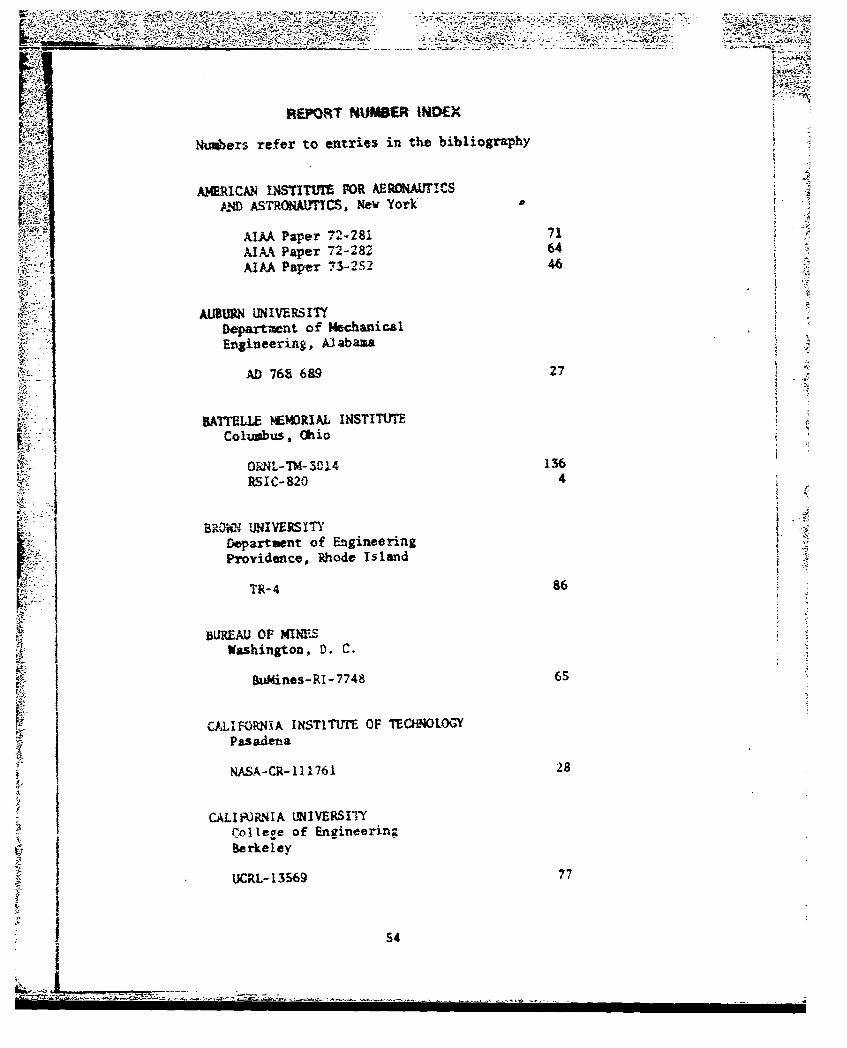
W~.ORT NMWASR IND~EX
Numers refer to entrieS in th~e bibliography
A)ERICAN U4$TTFUT 1OR AEnOIAUTICSLVD ASTROMAffCS, New York'
AJAA Paper "7L- 281 71PdA.A P aper 722264AIMA Paper 73-252 46
ALUNUNIVERSITYDepartment of MechanicalEtgineering, Alabaza
AD 768 6&9 27
BAITrLLE WM(I43tAL INSTITUTEColumbus. Ohio
0 i L-T M- $ 0.14 136RSIC-820 4
aRO0N UN IVE RS I inDepartment of EngineeringProvidence, Rh~ode Islan~d
TR- 4 86
BUREAU 0OF MINES-Washington, D. C.
Bui~ines-RI-7748 65
UALIFORNXA INSTITUTE~ OF TECKNOLOGYPas adenia
NASA-CR-111761 28
CALIFORNIA UN4IVE~RSITYP. 11coe of Engineerin2
t~ I Berkeley
UCr.L-13 569 7
J S4
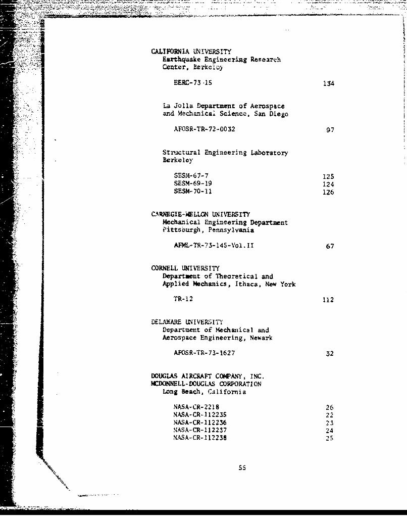
CALIFORNIA ANiERS1TY
Earthquake Engineering Res-arch"Center, Reike.
La Jolla Department of Aerospaceand Mechanical Science, San Diego
,.AOS-TR-72-0032 97
Structural Engineering LaboratoryBerke ey
SES?4-6 7-7 i2sSESM-69- 19 124SESM- 70-11 126
CN4-GIE-iELLN UNIVEWSITYMech&nica: Engineering DepartmntPittsburgh, Pennsylvania
j.AFML-TR-73-14S-Vol.II 67
CORMLL UNIVERSITYDepartment of Theoretical andApplied Mechanics, Ithaca, New York
TR-12 112
DELA•ARE i. IVER.I1TYDepartment of Mechaiiical andAe.ospace Engineering, Newark
AFOSR-TR-73-1627 32
DOUGLAS AIRCRAFT COMANY, INC.IMCDONNELL-LDOUGLAS CORPORATI ON
Long Beach, California
NASA-CR-2218 26WASA-CR-11223S 22
NASA-CR-112236 23NASA-CR-112237 24NASA-CR-112238 25
.755
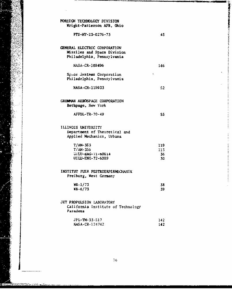
FOREIGN TEQINELOGY DIVISIONIWr~ight-Patterson AFB, Oh~io
PTD-HT-23-0276-73 45
GENERALL ELECTIC CORPORATIONmissiles and S'Pace DivisionPhiladelphia, Pennsylvania
NASA -f-10949614
Spi~ce' Systeoms CorporationPhiladelphia, Pennsylvania
NASA-CR-i119933 52
GRI134AN AEROSPACE CORPORATIONBetbpage. New York
AFFDL-TR-70-49 SS
ILLINOIS UN~IVERSTYDepartment of Theoretical andApplied Mechanics, Urbana
TIAM-3S3 119TIAM- 35611I uiL-cM;i~-~t~i436IJILU-J.-NG-72-6009 30
INSTITUFr FUER FESTKOERPERNE1"%MI KFreiburg, West Comay=
WB-1/73 38AWB-6/73 39
JET PROPULSION LABORATORYCalifornia Institute of TechnologyPasadena
JPL-T14-33-517 142NASA-CR-1247414 142
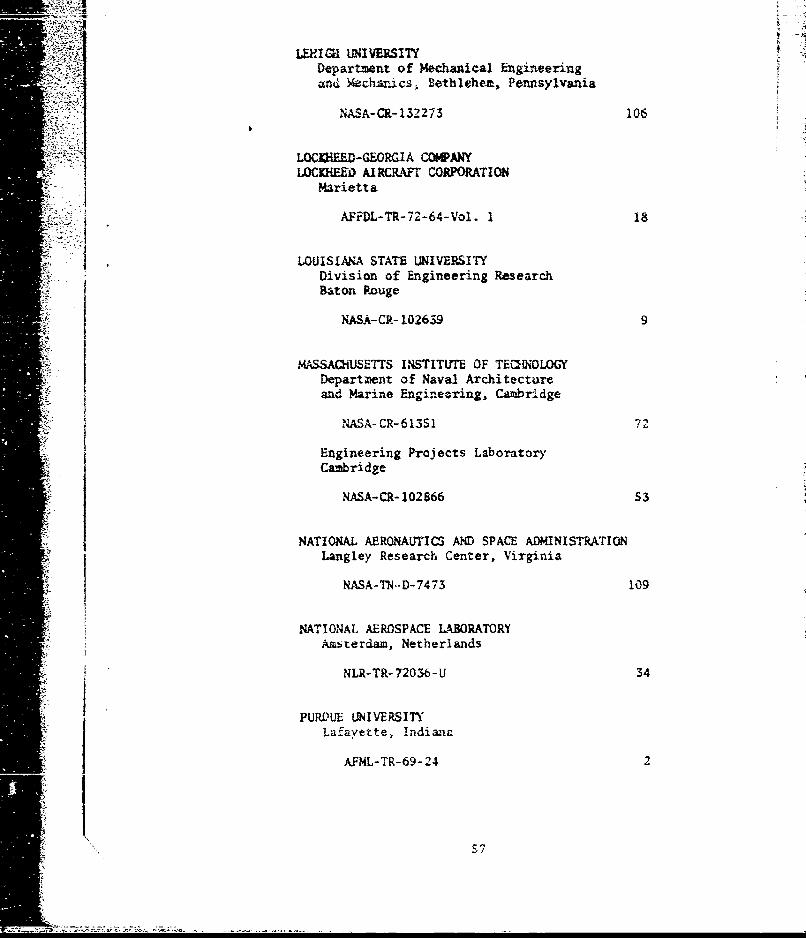
-- - Department of Mechanical Engineeringa•nd Wchsnics, Bethlehem, Pennsylvania
NASA-CR-132273 106
LOCKHUDH-GEORGIA COW ANYLOCKHEED AIRCRAFT CORPORATION
Marietta
AFPDL-TR- 72-64- Vol. 1 1
LOUISIANA STATE UNIVERSITYDivision of Engineering ResearchILBaton Rouge
NASA-CR- 102639 9
MASSAChUSETTS INSTITUTE OF TEaleOLOGYDepartment of Naval Architectureand Marine Engineering, Cambridge
NASA- CR-613S1 7
"Engineering Projects Laboratory"Cambridge
"NASA-CR- 102866 53
NATIONAL AERONAUTICS AND SPACE ADMINISTRATIONLangley Research Center, Virginia
NASA-TN--D-7473 109
NATIONAL AEROSPACE LABORATORYAmsterdam, Netherlands
NLR-TR- 72036-U 34
PURDUE UNIVERSITYLafayette, Indiana
AFML-TR-69- 24 2
:€1C
SOCIETY FOR EXflRLW-ITAL STRESS ANALYSISWestport, Connecticut
SESA Paper 1990A 17
TEWXA UNIVE•SITYStructures Fatigue ResearchLab*ratory, Austin
SFRL-TR-PSSO-12 143
TORONTO UNIVERSITYInstitute for Aerospace StudiesOnt ario
iUJTIAS-TN- 13 5
UNION CARBIDE CORPORATIONOak Ridge, Tennessee
V-1627 79
VIRGINIA POLYTEcMNIC INSTITu-M AND STATEUNIVERSITY, Department of Enr.gneeringSci .n.e and Mechanics, Blacksburg
VPI-E-73-17 130
WliITTAKER CORPORATIONSan Diego, California
USAAVLBSS-TR- 69- 25 63
I;;
[5
TRESIS !ND!EX
Num~bers rtfer to entries in tiie bib'iography
CHANG, D. J.............................13-- A Unive-rsity of California
FOWEWTNT J. E. , JR ..Louisiana State University
FCUSSE, 8. m..............................123Sta~ford University
HOLLIDAY, G. H...... ..... ... ... ..... ....127University of Houston
KULKAARNI, S. V. ........... ............. ... ..... ... ... ......130Virginia Polytechnic Institute
kZHRRTA, B. L ............................ 3?4cGiil University
PAHJA, M.H....... ... ... ..... ... .......University of Illinois
PEACCOCK, H. B.,R..........................87University of 'rennessee
WANG, C. Y.................119Univers-ity of Illiv~ois