Embed Size (px)
Citation preview
Specification 46DEFENCE ESTATESDelivering Estate Solutions to Defence Needs
Aviation fuel filtration
SPECIALIST SERVICESFUELS AND MECHANICALDEFENCE ESTATESMINISTRY OF DEFENCEDecember 1999
i

Spec 046Aviation fuel filtration
Spec 046Aviation fuel filtration
Foreword
This Specification was prepared under the patronage of the Defence Fuels andLubricants Distribution Committee.
This Specification is for the use of Top Level Budget Holders (TLBHs) forapplication by the Project Sponsors, Property Managers EstablishmentWorks Consultants (EWCs), Works Services Managers (WSMs) and other partiesinvolved in the specification and installation of aviation fuel filtration equipmentat petroleum storage depots, oil fuel depots and aviation fuel installations on theMinistry of Defence (MOD) Estate.
The principal users of this Specification are expected to be Project Sponsors, toinfluence the preparation of the Statement of Requirements: EWC specifiers andWSM designers, installers and maintainers for works which fall within theproperty services remit; and Project Managers, designers and installers forprojects.
For MOD Establishments occupied by United States Visiting Forces (USVF)additional requirements may apply in relation to United States MilitarySpecifications (Mil Spec).
This Specification incorporates the requirements of:
DBF STAN 49-3 Design and Performance Requirements of Fuel Filter WaterSeparators for Military Use
DBF STAN 49-5 Filter, Fluid, Pressure (Precoat Type for Aviation Fuels)
NATO STANAG 3583 Differential Pressure Gauges for Filter WaterSeparators
NATO STANAG 3967 Design and Performance Requirements for AviationFuel Filter Separator Vessels and Coalescer and Separator Elements.
and supercedes:
Standard Specification (M&E) No. 25 Precoat Filters, Filter WaterSeparators and Fuel Monitors for Aviation Fuel, DOE/PSA.
Amendments to this Specification will be advised by Defence Estates (DE)Technical Bulletin, issued to PROM and TLBH Works staff. It is theresponsibility of the user to check with the PROM or Project Sponsor ifamendments have been issued. There is a feedback sheet at Annex B forsuggested changes or developments to the document.
Spec 046 ForewordAviation fuel filtration
Technical advice and assistance can be obtained from DE. Approaches may bethrough local DE offices or directly to the Focal Point:
Head of Bulk Petroleum InstallationsSpecialist ServicesFuels and MechanicalDefence EstatesBlakemore DriveSUTTON COLDFIELDWest MidlandsB75 7RL
Notwithstanding that this document sets out the specification for filtrationequipment and is the MOD preferred solution, its use does not absolve a ProjectManager from any responsibility for the design, neither does its existenceconstrain him from using alternatives, provided such alternatives can bedemonstrated to provide a result of equal safety, quality and cost effectiveness.Attention is drawn to the requirement for Product Conformity Certification (PCC)for filter water separator vessels and elements. PCC shall be supported withdocumentary evidence that the vessel and elements are fully compliant with DEFSTAN 49-3 Design and Performance Requirements of Fuel Filter WaterSeparators for Military Use.
This Specification has been devised for the use of the Crown and its Contractorsin the execution of contracts for the Crown. The Crown hereby excludes allliability (other than liability for death or personal injury) whatsoever andhowsoever arising (including, but without limitation, negligence on the part of theCrown, its servants or agents) for any loss or damage however caused where theSpecification is used for any other purpose.
Compliance with a DE Specification will not of itself confer immunity from legalobligations.
Spec 046Aviation fuel filtration
Abbreviations
British StandardDefence EstatesDefence Estate OrganisationDefence Works ServicesEstablishment Works ConsultantIndex of Protection (for equipment), Institute of Petroleum(for publications)Ministry of DefenceProduct Conformity CertificationProperty ManagerTop Level Budget HolderWorks Services Manager
BSDEDEODWSEWCIP
MODPCCPROMTLBHWSM

Spec 046Aviation fuel filtration
Spec 046Aviation fuel filtration
Contents
FOREWORD
ABBREVIATIONS
CONTENTS
11.11.21.3
22.12.22.32.42.52.62.72.82.92.102.112.122.132.142.15
33.13.23.33.43.5
44.14.24.34.44.5
INTRODUCTIONSCOPEARRANGEMENTGENERAL REQUIREMENTS
PRECOAT FILTERSAPPLICATIONSCOPE OF SUPPLYDOCUMENTATION REQUIREMENTSPERFORMANCEPRESSURE CONTAINMENTFLANGE TERMINATIONAUXILIARY PIPINGAUXILIARY EQUIPMENTMEDIAELECTRIC MOTORSACCESSMATERIALS OF CONSTRUCTIONPAINTINGNAMEPLATESTESTING
FILTER WATER SEPARATORSAPPLICATIONSCOPE OF SUPPLYDOCUMENTATION REQUIREMENTSPRODUCT CONFORMITY CERTIFICATIONPERFORMANCE, DESIGN, CONSTRUCTION AND TESTINGREQUIREMENTS
FUEL MONITORSAPPLICATIONSCOPE OF SUPPLYDOCUMENTATION REQUIREMENTSMONITOR AND ELEMENT PERFORMANCE QUALIFICATIONDESIGN, CONSTRUCTION AND TESTING REQUIREMENTS
iii
V
1111
3333444445566666
777788
111 1111 11212
vii
Spec 046 ContentsAviation fuel filtration
AB
ANNEXESDATA SHEETSCHANGE SUGGESTION FORM
1521
Spec 046Aviation fuel filtration
1 Introduction
1.1 SCOPE
This Specification has been produced in order to specify the requirements for thedesign and construction of aviation fuel filtration equipment on the MOD Estate.It is equally applicable to new build and refurbishment works.
This Specification is applicable to:
petroleum storage depotsoil fuel depotsaviation fuel installations.
This Specification only applies to aviation fuels for use in jet aircraft ie.AVCAT/AVTUR. It does not apply to AVGAS nor ground fuels such as CIVGASor diesel.
1.2 ARRANGEMENT
Section 1 indicates the application of this Specification to the MOD Estate andindicates the general requirements that all fuel filtration equipment should meet.
Section 2 advises the requirements for specification, scope of supply, performanceand testing for precoat filters.
Section 3 defines the requirements for filter water separators in terms of scope ofsupply, performance, type of equipment and testing requirements.
Section 4 provides information concerning the scope of supply, performance andtesting requirements for fuel monitors.
Annex A contains the data sheets, which should be initiated by the organisationrequiring the equipment and completed by the equipment manufacturer.
Annex B contains the Change Suggestion Form.
1.3 GENERAL REQUIREMENTS
1.3.1 Environmental conditions
All equipment shall be designed for outdoor installation. Items shall beunaffected by frost, tropical rain and high humidity and shall be suitable for theambient temperatures stated in the data sheets.
1.3.2 Design pedigree
Only standard designs in current production, with a proven history of reliableoperation in hydrocarbon service should be offered. Prototype or unprovendesigns will not be considered.
Spec 046 1 IntroductionAviation fuel filtration
1.3.3 Preservation
Equipment shall be prepared for despatch to site as follows:
all openings to atmosphere shall be closed by means of flanges or plugssecurely bolted or screwed in placeoil filled compartments or equipment shall be emptied and a rust inhibitorappliedsuitable supports shall be provided for internal parts which might becomedamaged in transit.
Any special requirements for the removal of preservative shall be clearlyindicated on the equipment and repeated in the commissioning instructions.
1.3.4 Special tools and spare parts
The equipment manufacturer shall provide one set of commissioning spares andspecial tools, together with a list of recommended operating spares, for a two yearperiod.
Spec 046Aviation fuel filtration
2 Precoat filters
2.1 APPLICATION
The precoat filter is installed at the aviation fuel installation at the receiving endof all cross-country pipelines to remove pipeline solids contamination.
2.2 SCOPE OF SUPPLY
The precoat filter manufacturer's scope of supply shall include, but not be limitedto, the following for each monitor:
filterinitial media fillsystem for applying and maintaining correct media level on the mediasupportssystem for discharging spent media and contaminants to a slops tanksystem for mixing suspensions of media with aviation fueldifferential pressure gaugerelief valveautomatic air ventpumps and motors as required by the manufacturer's designauxiliary pipeworkinspection and testingpainting and preservationdocumentationspecial tools and spare parts.
The following items are excluded from the precoat filter manufacturer's scope ofsupply:
slops tanksite installation.
2.3 DOCUMENTATION REQUIREMENTS
Proposal requirements:
general arrangement drawing showing overall dimensions, weights, location,type and size of all termination points; foundation requirements and elementremoval distancescompleted data sheetscross-sectional drawing showing internal layout of the precoat filterschematic indicating the manufacturer's scope of supply.
Spec 046 2 Precoat filtersAviation fuel filtration
'As-installed' requirements:
all of the documentation submitted at the time of the proposal but revised toindicate a true record of the equipment suppliedrelief valve test certificationdifferential pressure gauge calibration certificatehydrostatic test certificationinstallation and commissioning proceduresoperation and maintenance manuals.
2.4 PERFORMANCE
The performance requirements are stated in Section 6 of DEF STAN 49-5 Filter,Fluid, Pressure (Precoat Type for Aviation Fuels).
The filter manufacturer shall complete the pressure drop and holding capacitysections of the data sheet. The holding capacity is defined as the time taken forthe maximum pressure drop to be reached at the rated flow rate for various inletcontamination levels.
2.5 PRESSURE CONTAINMENT
Precoat filters shall be designed and constructed to BS 5500 Specification forUnfired Fusion Welded Pressure Vessels or any other national pressure vesselcode (eg. ASME).
The design pressure and temperature shall be defined on the data sheet.
Any element or part of the vessel, which is subjected to differential pressure dueto normal flow of fuel shall be capable of being tested at twice the differentialpressure without any damage.
2.6 FLANGE TERMINATIONS
All termination flanges shall be in accordance with BS 1560 Part 3 Section 3.1Specification for Steel Flanges. Flanges shall be Class 150 unless otherwisestated on the data sheet. Bolt holes shall straddle centrelines.
2.7 AUXILIARY PIPING
Auxiliary piping shall be in accordance with FS 05 Specification for SpecialistWorks on Petroleum Installations - Mechanical, DWS.
2.8 AUXILIARY EQUIPMENT
The following equipment shall be fitted to each precoat filter:
a) Automatic air vent.
b) Pressure relief valve in accordance with FS 05 Specification for SpecialistWorks on Petroleum Installations - Mechanical, DWS sized and selected by theprecoat filter manufacturer.
c) Piston type differential pressure gauge complying with the requirements ofAnnex C of DEF STAN 49-3 Design and Performance Requirements of FuelFilter Water Separators for Military Use.
Spec 046 2 Precoat filtersAviation fuel filtration
d) A differential pressure sensing instrument capable of actuating a local audiblealarm and an audible and visual alarm in the control room. The instrumentshall be certified for the hazardous area classification, gas grouping andenvironmental protection as defined on the data sheet.
e) Sight glasses on the fuel inlet and outlet pipework in accordance with FS 05Specification for Specialist Works on Petroleum Installations - Mechanical,DWS.
f) Lockable drain valves at the low points of all tanks, vessels and pumps.
2.9 MEDIA
The following requirements apply to the precoat filter media:
a) The media shall be compatible with the fuel and its additives and shall notcause any change in the fuel that would prevent it from meeting itsspecification. The use of asbestos is not permitted.
b) Media retention shall be by an adequately supported stainless steel meshmaterial. The design of the retention system shall allow backflushing of themedia and be such that neither mechanical handling equipment ordisconnection of the main pipework is required.
c) The filter shall be arranged such that spent media and dirt shall bebackflushed to a slops tank. During backflushing, all flow shall be directed tothe slops tank and no filtered fuel shall be produced. The media system shall bearranged such that the main fuel flow is used for media depositioncommensurate with filtered fuel being produced. The time for a complete mediachange ie. backflushing and deposition shall not be longer than five minutes atthe rated fuel flow.
d) The need for a media change shall be initiated by the differential pressurereaching the value specified by the manufacturer on the data sheet.
2.10 ELECTRIC MOTORS
Motors shall be of the totally enclosed squirrel cage induction type complyingwith the relevant parts of BS 4999 General Requirements for Rotating ElectricalMachines and BS 5000 Rotating Electrical Machines of Particular Types or forParticular Applications. They shall be certified for the hazardous areaclassification, gas grouping and environmental protection as defined on the datasheet. They shall have characteristics to suit the electricity supply and therequired power output and shall be continuously rated. They shall be fitted withgrease lubricated ball or roller bearings, including a thrust bearing if required.Lubrication of bearings shall be possible without the need for any dismantling.
The motor shall have a rating not less than 115% of the power required at theduty point.
Motor windings insulation shall be Class F.
Motor condensation heaters shall be provided with connections, which shall bebrought out to a separate terminal box.
Spec 046 2 Precoat filtersAviation fuel filtration
2.11 ACCESS
The vessel design shall allow access for the inspection of all interior surfaceswhen opened for. maintenance purposes.
2.12 MATERIALS OF CONSTRUCTION
Materials in contact with the fuel shall not be affected by the fuel, by water, or bywater containing soluble fuel additives nor shall the materials have any effectupon the fuel. Metals and alloys that are fuel wetted shall be corrosion resistantor protected by a coating system in accordance with Spec 032 Internal Coating ofAviation Fuel Tanks, DEO. Dissimilar metals that will initiate and promotecorrosion, if in contact, shall not be allowed. Copper, copper alloys, light metalalloys containing more than 4% copper, zinc or zinc alloys, cadmium, lead andlead alloys shall not be used in components exposed to the fuel.
2.13 PAINTING
The equipment manufacturer shall paint all external surfaces to his standardpaint system suitable for an exposed saline environment. The paint system shallbe resistant to the fuel.
2.14 NAMEPLATES
Each precoat filter shall be provided with a permanently attached nameplatemade of non-corrodible material detailing:
manufacturer's name and serial numberdesign code, pressure (bar g) and temperature (°C)hydrostatic test pressure (bar g)rated capacity (m3/hr)quantity and stock number of the elementsdate of manufacture.
Additional information may be required to be displayed dependent on the designcode.
2.15 TESTING
2.15.1 Hydrostatic testing
All pressure containing parts shall be hydrostatically tested in accordance withthe relevant design code to which they are designed and constructed.
2.15.2 Motors
Motors shall be tested at the motor manufacturer's works in accordance with the'Routine Check Tests', as detailed in BS 4999 Part 143 General Requirements forRotating Electrical Machines: Specification for Tests.
2.15.3 Filtration
Filtration tests shall be undertaken in accordance with Section 14 of DEF STAN49-5 Filter, Fluid, Pressure (Precoat Type for Aviation Fuels).
Spec 046Aviation fuel filtration
3 Filter water separators
3.1 APPLICATION
Filter water separators are used to remove dirt, particulate and watercontamination from hydrocarbons. The separator is of a two stage design, thefirst set of elements coalesce water droplets in the fuel, whilst the second removesparticulate matter.
3.2 SCOPE OF SUPPLY
The filter water separator manufacturer's scope of supply shall include, but notbe limited to, the following for each separator:
separatorset of coalescer and separator elementsdifferential pressure gaugerelief valveautomatic air ventautomatic water drain valveautomatic fuel shut off valve (when specified on the data sheet)differential pressure shut-off feature (when specified on the data sheet)differential pressure alarm (when specified on the data sheet)inspection and testingpainting and preservationdocumentationspecial tools and spare parts.
The following items are excluded from the filter water separator manufacturer'sscope of supply:
site installation.
3.3 DOCUMENTATION REQUIREMENTS
Proposal requirements:
general arrangement drawing showing overall dimensions, weights, location,type and size of all termination points; foundation requirements and elementremoval distancescompleted data sheetscross-sectional drawing showing internal layout of all elements and flowpaths.
'As-installed' requirements:
all of the documentation submitted at the time of the proposal but revised toindicate a true record of the equipment suppliedrelief valve test certificationdifferential pressure gauge calibration certificate
Spec 046 3 Filter water separatorsAviation fuel filtration
hydrostatic test certificationinstallation and commissioning proceduresoperation and maintenance manuals.
3.4 PRODUCT CONFORMITY CERTIFICATION
Before any filter water separator vessel or elements can be offered to the MOD,the manufacturer shall have supplied to the Service Authority named in thecontract, Product Conformity Certification.
The requirements for Product Conformity Certification are defined in DEF STAN49-3 Design and Performance Requirements of Fuel Filter Water Separators forMilitary Use.
3.5 PERFORMANCE, DESIGN, CONSTRUCTION AND TESTING REQUIREMENTS
The requirements for performance, design, construction and testing are defined inDEF STAN 49-3 Design and Performance Requirements of Fuel Filter WaterSeparators for Military Use, unless modified by the following clauses.
3.5.1 Materials of construction
Materials in contact with the fuel shall not be affected by the fuel, by water, or bywater containing soluble fuel additives, nor shall the materials have any effectupon the fuel. Metals and alloys that are fuel wetted shall be corrosion resistantor protected by a coating system in accordance with Spec 032 Internal Coating ofAviation Fuel Tanks, DEO. Dissimilar metals that will initiate and promotecorrosion, if in contact, shall not be allowed. Copper, copper alloys, light metalalloys containing more than 4% copper, zinc or zinc alloys, cadmium, lead andlead alloys shall not be used in components exposed to the fuel.
3.5.2 Painting
The equipment manufacturer shall paint all external surfaces to his standardpaint system suitable for an exposed saline environment. The paint system shallbe resistant to the fuel. Inlet and outlet piping connections are to be permanentlymarked.
3.5.3 Auxiliary Equipment
The following equipment shall be fitted to each filter water separator:
a) Automatic air vent.
b) Pressure relief valve in accordance with FS 05 Specification for SpecialistWorks on Petroleum Installations - Mechanical, DWS sized and selected bythe precoat filter manufacturer.
c) Piston type differential pressure gauge complying with the requirements ofAnnex C of DEF STAN 49-3 Design and Performance Requirements of FuelFilter Water Separators for Military Use.
d) An armoured sight glass shall be installed on the sump to observe the level ofwater accumulation. The sight glass shall extend to; as close as possible to orbelow the bottom of the sump and shall contain a coloured density sensitiveball that floats on water and sinks in fuel. The sight glass shall be equippedwith stainless steel isolation valves and a bottom drain cock.
Spec 046 3 Filter water separatorsAviation fuel filtration
e) Inlet and outlet sample points complying with the requirements of Annex Bof DEF STAN 49-3 Design and Performance Requirements of Fuel FilterWater Separators for Military Use.
f) Manual drain valve complying with the requirements of Annex B of DEFSTAN 49-3 Design and Performance Requirements of Fuel Filter WaterSeparators for Military Use.
g) An automatic drain valve shall be fitted complying with the requirements ofAnnex B of DEF STAN 49-3 Design and Performance Requirements of FuelFilter Water Separators for Military Use. A facility shall be provided tofunctionally test the operation of the drain valve and (when fitted) the fuelshut-off valve.
h) An automatic fuel shut-off valve shall only be provided if specified on the datasheet. The valve shall be installed on the outlet pipework and shall behydraulically operated. The valve shall normally be open but shall close wheneither, the fuel flow through the valve exceeds the design flow of theseparator or if the water draining capacity of the automatic drain valve isexceeded. Normal operation of the separator shall continue automaticallyafter water has drained from the sump or the fuel flow has reduced.
i) When specified on the data sheet, a differential pressure shut-off featureshall be provided, which will stop the flow when the maximum differentialpressure across the filter is reached. After each shut-off, the feature shall bemanually reset to permit normal operation.
j) If specified on the data sheet, a differential pressure sensing instrument shallbe fitted, which shall be capable of providing an audible and visual alarm inthe control room. The instrument shall be certified for the hazardous areaclassification, gas grouping and environmental protection as defined on thedata sheet.
Spec 046 3 Filter water separatorsAviation fuel filtration
10
Spec 046Aviation fuel filtration
4 Fuel monitors
4.1 APPLICATION
Monitors shall be installed at aviation fuel installations downstream of the filterwater separators. The fuel monitor shall fail safe in that it shall shut off the flowof fuel in the event of excessive concentrations of free water being present in thefuel.
4.2 SCOPE OF SUPPLY
The fuel monitor manufacturer's scope of supply shall include, but not be limitedto, the following for each monitor:
monitorset of elementsdifferential pressure gaugerelief valveautomatic air ventinspection and testingpainting and preservationdocumentationspecial tools and spare parts.
The following items are excluded from the fuel monitor manufacturer's scope ofsupply:
site installation.
4.3 DOCUMENTATION REQUIREMENTS
Proposal requirements:
general arrangement drawing showing overall dimensions, weights, location,type and size of all termination points; foundation requirements and elementremoval distancescompleted data sheetscross-sectional drawing showing internal layout of all elements and flowpaths.
'As-installed' requirements:
all of the documentation submitted at the time of the proposal but revised toindicate a true record of the equipment suppliedrelief valve test certificationdifferential pressure gauge calibration certificatehydrostatic test certificationinstallation and commissioning proceduresoperation and maintenance manuals.
11
Spec 046 4 Fuel monitorsAviation fuel filtration
4.4 MONITOR AND ELEMENT PERFORMANCE QUALIFICATION
The monitor and elements shall be tested in accordance with the requirements of'Specifications and Qualification Procedures - Aviation Fuel Filter Monitors withAbsorbent Type Elements', IP.
The test fuel shall be F 34.
4.5 DESIGN, CONSTRUCTION AND TESTING REQUIREMENTS
The requirements for design, construction and testing are defined inSpecifications and Qualification Procedures - Aviation Fuel Filter Monitors withAbsorbent Type Elements, IP unless modified by the following clauses.
4.5.1 Flange terminations
All termination flanges shall be in accordance with BS 1560 Part 3 Section 3.1Specification for Steel Flanges. Flanges shall be Class 150 unless otherwisestated on the data sheet. Bolt holes shall straddle centrelines.
4.5.2 Auxiliary equipment
The following equipment shall be fitted to each fuel monitor:
a) Automatic air vent.
b) Pressure relief valve in accordance with FS 05 Specification for SpecialistWorks on Petroleum Installations - Mechanical, DWS sized and selected by thefuel monitor manufacturer.
c) Piston type differential pressure gauge complying with the requirements ofAnnex C of DEF STAN 49-3 Design and Performance Requirements of FuelFilter Water Separators for Military Use.
d) Lockable sample point valves on the inlet and outlet connections.
e) Lockable drain valves at the low points of all internal compartments.
4.5.3 Materials of construction
Materials in contact with the fuel shall not be affected by the fuel, by water, or bywater containing soluble fuel additives, nor shall the materials have any effectupon the fuel. Metals and alloys that are fuel wetted shall be corrosion resistantor protected by a coating system in accordance with Spec 032 Internal Coating ofAviation Fuel Tanks, DEO. Dissimilar metals that will initiate and promotecorrosion, if in contact, shall not be allowed. Copper, copper alloys, light metalalloys containing more than 4% copper, zinc or zinc alloys, cadmium, lead andlead alloys shall not be used in components exposed to the fuel.
4.5.4 Painting
The equipment manufacturer shall paint all external surfaces to his standardpaint system suitable for an exposed saline environment. The paint system shallbe resistant to the fuel.
12
Spec 046 4 Fuel monitorsAviation fuel filtration
4.5.5 Nameplates
Each fuel monitor shall be provided with a permanently attached nameplatemade of non-corrodible material detailing:
manufacturer's name and serial numberdesign code, pressure (bar g) and temperature (°C)hydrostatic test pressure (bar g)rated capacity (mVhr)quantity and stock number of the elementsdate of manufacture.
Additional information may be required to be displayed dependent on the designcode.
13
Spec 046 4 Fuel monitorsAviation fuel filtration
14
Spec 046Aviation fuel filtration
Annex A Data sheets
15
Spec 046 Annex A DatasheetsAviation fuel filtration
16
Spec 046Aviation fuel filtration
Annex A Datasheets
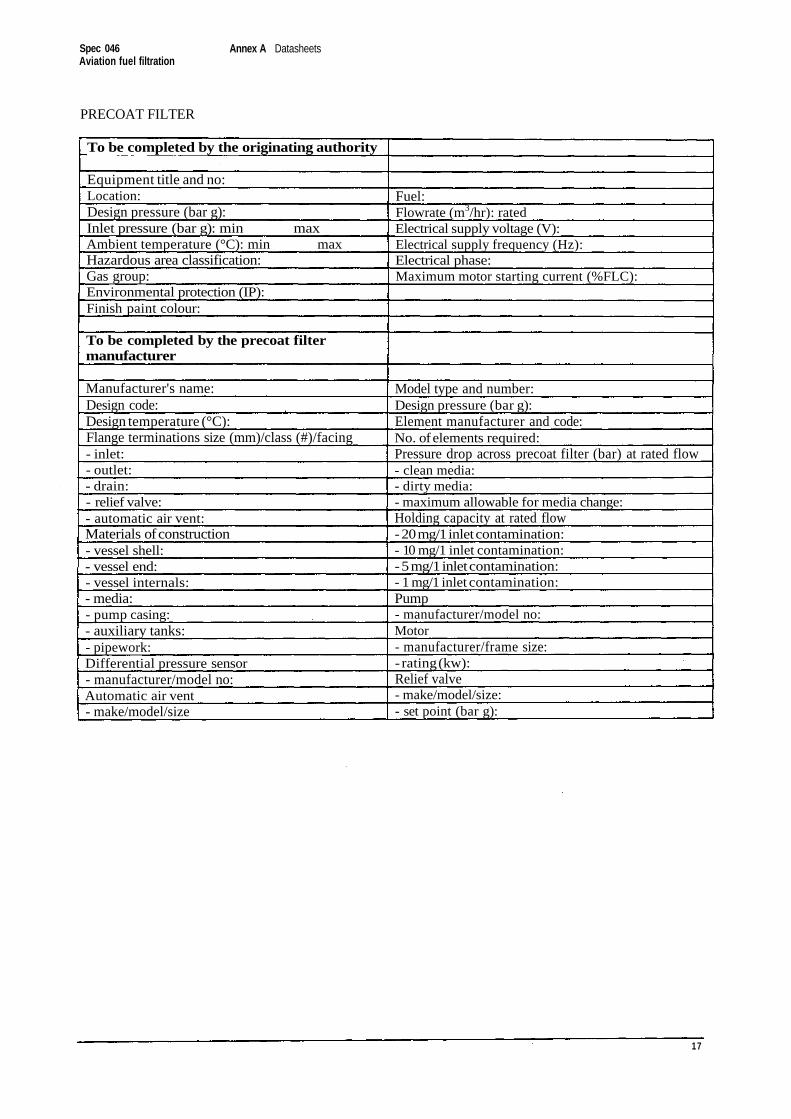
PRECOAT FILTER
To be completed by the originating authority
Equipment title and no:Location:Design pressure (bar g):Inlet pressure (bar g): min maxAmbient temperature (°C): min maxHazardous area classification:Gas group:Environmental protection (IP):Finish paint colour:
To be completed by the precoat filtermanufacturer
Manufacturer's name:Design code:Design temperature (°C):Flange terminations size (mm)/class (#)/facing- inlet:- outlet:- drain:- relief valve:- automatic air vent:Materials of construction- vessel shell:- vessel end:- vessel internals:- media:- pump casing:- auxiliary tanks:- pipework:Differential pressure sensor- manufacturer/model no:Automatic air vent- make/model/size
Fuel:Flowrate (m3/hr): ratedElectrical supply voltage (V):Electrical supply frequency (Hz):Electrical phase:Maximum motor starting current (%FLC):
Model type and number:Design pressure (bar g):Element manufacturer and code:No. of elements required:Pressure drop across precoat filter (bar) at rated flow- clean media:- dirty media:- maximum allowable for media change:Holding capacity at rated flow- 20 mg/1 inlet contamination:- 10 mg/1 inlet contamination:- 5 mg/1 inlet contamination:- 1 mg/1 inlet contamination:Pump- manufacturer/model no:Motor- manufacturer/frame size:- rating (kw):Relief valve- make/model/size:- set point (bar g):
17
Spec 046Aviation fuel filtration
Annex A Datasheets
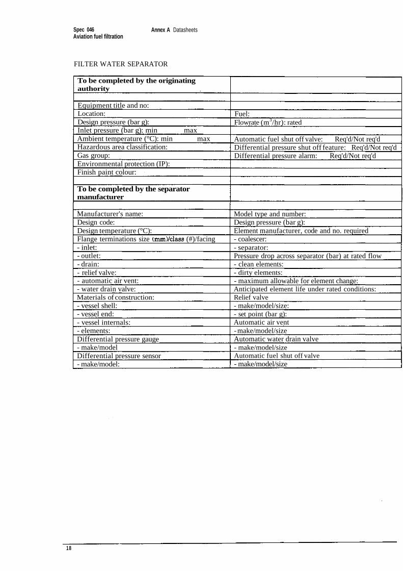
FILTER WATER SEPARATOR
To be completed by the originatingauthority
Equipment title and no:Location:Design pressure (bar g):Inlet pressure (bar g): min maxAmbient temperature (°C): min maxHazardous area classification:Gas group:Environmental protection (IP):Finish paint colour:
To be completed by the separatormanufacturer
Manufacturer's name:Design code:Design temperature (°C):Flange terminations size (#)/facing- inlet:- outlet:- drain:- relief valve:- automatic air vent:- water drain valve:Materials of construction:- vessel shell:- vessel end:- vessel internals:- elements:Differential pressure gauge- make/modelDifferential pressure sensor- make/model:
Fuel:Flowrate (m3/hr): rated
Automatic fuel shut off valve: Req'd/Not req'dDifferential pressure shut off feature: Req'd/Not req'dDifferential pressure alarm: Req'd/Not req'd
Model type and number:Design pressure (bar g):Element manufacturer, code and no. required- coalescer:- separator:Pressure drop across separator (bar) at rated flow- clean elements:- dirty elements:- maximum allowable for element change:Anticipated element life under rated conditions:Relief valve- make/model/size:- set point (bar g):Automatic air vent- make/model/sizeAutomatic water drain valve- make/model/sizeAutomatic fuel shut off valve- make/model/size
18
Spec 046Aviation fuel filtration
Annex A Data sheets
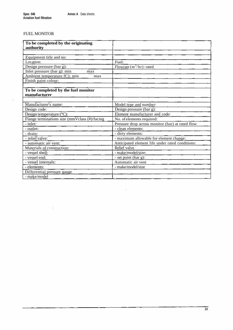
FUEL MONITOR
To be completed by the originatingauthority
Equipment title and no:Location:Design pressure (bar g):Inlet pressure (bar g): min maxAmbient temperature fC): min maxFinish paint colour:
To be completed by the fuel monitormanufacturer
Manufacturer's name:Design code:Design temperature (°C):Flange terminations size (mmVclass (#)/facing- inlet:- outlet:- drain:- relief valve:- automatic air vent:Materials of construction:- vessel shell:- vessel end:- vessel internals:- elements:Differential pressure gauge- make/model
Fuel:Flowrate (m3/hr): rated
Model type and number:Design pressure (bar g):Element manufacturer and code:No. of elements required:Pressure drop across monitor (bar) at rated flow- clean elements:- dirty elements:- maximum allowable for element change:Anticipated element life under rated conditions:Relief valve- make/model/size:- set point (bar g):Automatic air vent- make/model/size
19
Spec 046 Annex A DatasheetsAviation fuel filtration
20
Spec 046Aviation fuel filtration
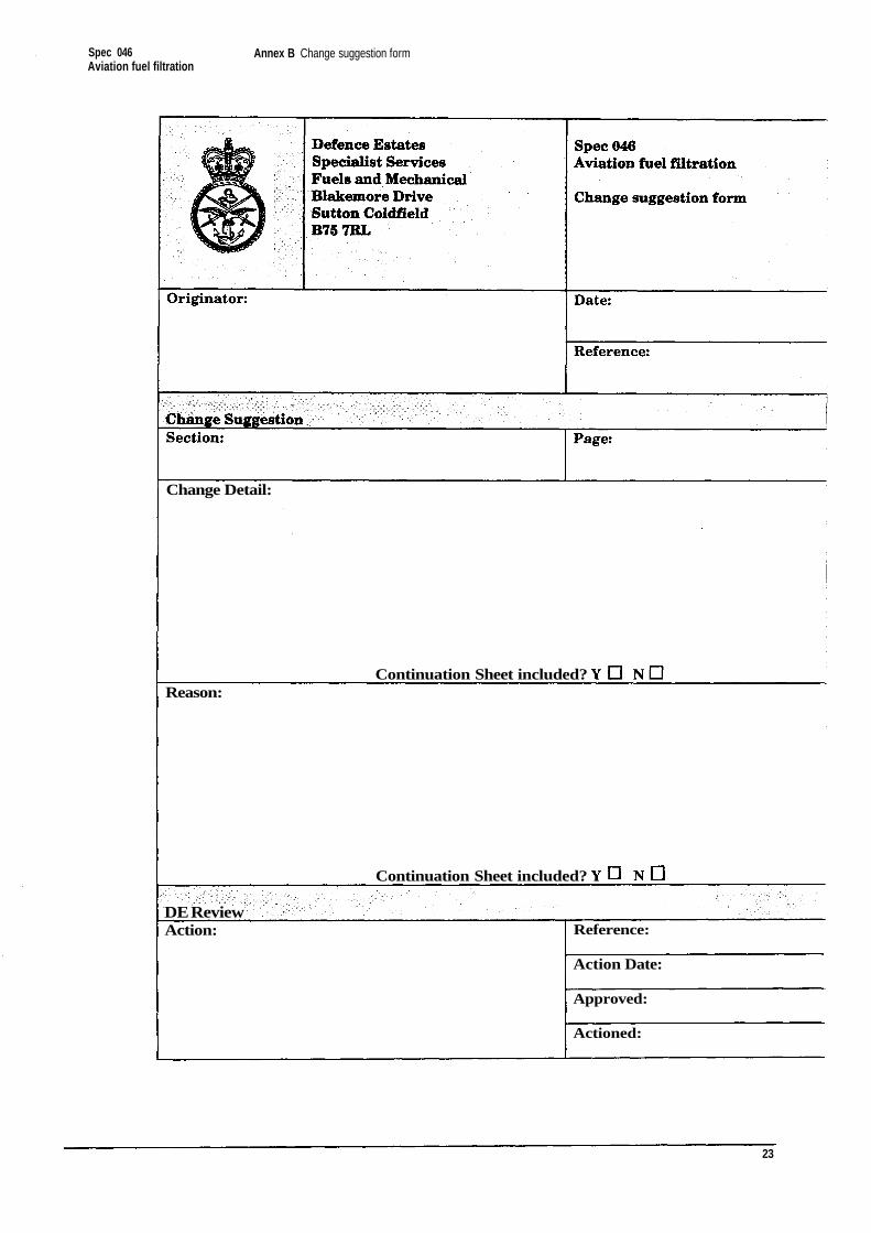
Annex B Change suggestionform
21
Spec 046 Annex B Change suggestion formAviation fuel filtration
22
Spec 046Aviation fuel filtration
Annex B Change suggestion form
Change Detail:
Reason:
DE ReviewAction: Reference:
Action Date:
Approved:
Actioned:
23
Continuation Sheet included?
Continuation Sheet included?
Spec 046 Annex B Change suggestion formAviation fuel filtration
24
![Implementation Limitations of STANAG 1008 Design ...1399 [3] is overlapped with STANAG-1008 [2]. The following analysis will be based on STANAG 1008 (edition 9) [2], which is the NATO](https://img.pdfslide.net/doc/110x75/61393125a4cdb41a985b8c5e/implementation-limitations-of-stanag-1008-design-1399-3-is-overlapped-with.jpg)