Embed Size (px)
Citation preview

BGE.COM
Natural gas and electric service guideFor commercial, industrial and residential customers

i i
One call to Miss Utility can savetime, money and lives.
Before you pick up any equipment, pick up the phone and call Miss Utility. Miss Utility will notify all applicable utility companies and see to it that your job site is marked for all underground utility lines. One simple phone call can save you the time
and hassle of dealing with job site mistakes and delays. Not to mention decrease liability, prevent damage, reduce injuries and possibly save lives. After all, safety is everyone’s job.
Call Miss Utility, at least 48 hours prior to work, at 811 or 1.800.257.7777.
Dig Safely CHECKLIST
1. Call Miss Utility at 811 or 1.800.257.7777 at least 48 hours prior to work.2. Allow the required time for utilities to mark the underground lines.3. Respect and protect all marks/flags.4. Excavate with care. Take all reasonable actions to properly protect, support and
backfill underground utility lines.5. Immediately notify the utility if an underground utility line is damaged.6. If damage creates an emergency, take immediate steps to safeguard life, health
and property.
Please check with your individual jurisdictions with regard to waiting times and specific digging guidelines.
For more information, contact Miss Utility or check online at www.missutility.net.
Before you dig, every dig. MISS UTILITY 811 or 1.800.257.7777
It’s the law.
i

i i
INTRODUCTION
BGE provides this manual as a briefing for the building community about installing natural gas and electric service—with guidelines important to developers, general contractors, builders, architects, engineers, and licensed electricians and plumbers.
Whether you're planning new construction, increasing your energy service needs, relocating BGE equipment, or converting an existing home or facility to natural gas, we welcome the opportunity to work with you on your next project. The information you'll find in this booklet is provided to help keep your project on track.
The procedures and specifications in this manual apply to both commercial and industrial projects and residential projects which include the following:
• New commercial or non-residential building.• Single residential homes (new or existing), apartments, condominiums and residential
developments.• Barns, garages, traffic signals, CATV power supplies, cell sites or traffic cameras.• Temporary service for residential projects, including construction or sales trailer. • Temporary service for commercial & industrial projects, including construction or.
sales trailer and apartments or condominiums.• Service increases to existing commercial or non-residential building.• Relocation/removal of existing BGE non-residential facilities.
Our goal is to work with you to install natural gas and electric service promptly and safely while meeting all construction codes and safety standards. Now and in the future, we’re committed to providing safe and reliable natural gas and electric service.
This publication is a guide to the BGE’s requirements and does not cover all the rules and regulations. We hope the information that follows answers your questions and guides you through the process. If there’s anything we haven’t made clear, please call us:
800.233.1854
A PDF version of this manual can be found on the New Construction Services section of bge.com
i
iii
TABLE OF CONTENT
GENERAL INFORmATION The Four Stages of Our Process . . . . . . . . . . . . . . . . . . . . . . . . . . . . . . . . . . . . . . . . . . . . . . 3–6Important Rules, Regulations and Responsibilities for Gas & Electric Service . . . . . . . . . . . 7–8Electric Retail Tariff . . . . . . . . . . . . . . . . . . . . . . . . . . . . . . . . . . . . . . . . . . . . . . . . . . . . . . . . . . 9Gas Service Tariff . . . . . . . . . . . . . . . . . . . . . . . . . . . . . . . . . . . . . . . . . . . . . . . . . . . . . . . . . . 10Outdoor Lighting . . . . . . . . . . . . . . . . . . . . . . . . . . . . . . . . . . . . . . . . . . . . . . . . . . . . . . . . . . . 11Temporary Electric Service . . . . . . . . . . . . . . . . . . . . . . . . . . . . . . . . . . . . . . . . . . . . . . . . . . . 11Relocation of BGE Lines and Equipment . . . . . . . . . . . . . . . . . . . . . . . . . . . . . . . . . . . . . . . . 11Temporary Electric Service from Pad-Mounted Transformer—Single Outdoor Meter . . . . . . . 12 Temporary Electric Service from Overhead Transformer—Single Outdoor Meter . . . . . . . . . . 13 Service Drop Clearances for Residential and Commercial Properties . . . . . . . . . . . . . . . . . . . 14 Small Generator Interconnections . . . . . . . . . . . . . . . . . . . . . . . . . . . . . . . . . . . . . . . . . . . . . . 15 PADmOUNTED EqUIPmENT INFORmATION Transformer Location Requirements . . . . . . . . . . . . . . . . . . . . . . . . . . . . . . . . . . . . . . . . . 17–22Traffic Protection for Pad-Mounted Transformers . . . . . . . . . . . . . . . . . . . . . . . . . . . . . . . . . . 23Transformer Pad Specifications . . . . . . . . . . . . . . . . . . . . . . . . . . . . . . . . . . . . . . . . . . . . . 24–25BGE Pad-Mounted Switchgear Location Requirements . . . . . . . . . . . . . . . . . . . . . . . . . . . . . 26Minimum Space Requirements for BGE 13KV Pad-Mounted Equipment . . . . . . . . . . . . . . . . 27Materials Available from BGE Contractor Supplier . . . . . . . . . . . . . . . . . . . . . . . . . . . . . . . . . . 28 COmmERCIAL & INDUsTRIALIntroduction . . . . . . . . . . . . . . . . . . . . . . . . . . . . . . . . . . . . . . . . . . . . . . . . . . . . . . . . . . . . . . . 31Conditions of Electric Supply . . . . . . . . . . . . . . . . . . . . . . . . . . . . . . . . . . . . . . . . . . . . . . . 32–34Electric Service Available . . . . . . . . . . . . . . . . . . . . . . . . . . . . . . . . . . . . . . . . . . . . . . . . . . . . 35Increase in Load to Existing Customers (Heavy-Up) . . . . . . . . . . . . . . . . . . . . . . . . . . . . . . . . 36Installations Requiring Special Consideration . . . . . . . . . . . . . . . . . . . . . . . . . . . . . . . . . . . . . 36Starting Equipment . . . . . . . . . . . . . . . . . . . . . . . . . . . . . . . . . . . . . . . . . . . . . . . . . . . . . . . . . 36Condition of Gas Supply . . . . . . . . . . . . . . . . . . . . . . . . . . . . . . . . . . . . . . . . . . . . . . . . . . . . . 37Gas Services Available . . . . . . . . . . . . . . . . . . . . . . . . . . . . . . . . . . . . . . . . . . . . . . . . . . . . . . 38Increase in Load to Existing Customer . . . . . . . . . . . . . . . . . . . . . . . . . . . . . . . . . . . . . . . . . . 38Gas and Electric Meter Requirements . . . . . . . . . . . . . . . . . . . . . . . . . . . . . . . . . . . . . . . . 39–40Electric Meter Socket Locations . . . . . . . . . . . . . . . . . . . . . . . . . . . . . . . . . . . . . . . . . . . . . . . 40Commercial & Industrial Meter—Traffic Protection . . . . . . . . . . . . . . . . . . . . . . . . . . . . . . . . . 41Sample Customer Site Plan—Single Commercial Site . . . . . . . . . . . . . . . . . . . . . . . . . . . . . . 42
CONDUITSpecifications for Customer Installation of Conduits . . . . . . . . . . . . . . . . . . . . . . . . . . . . . 45–473-Phase Transformer Pad Dimension Detail/Conduit Detail . . . . . . . . . . . . . . . . . . . . . . . . . . 481-Phase Transformer Pad Dimension Detail/Conduit Detail . . . . . . . . . . . . . . . . . . . . . . . . . . . 49Turning Conduits into Transformer Pads . . . . . . . . . . . . . . . . . . . . . . . . . . . . . . . . . . . . . . . . . 50Standard Duct Bank Arrangement/Installation . . . . . . . . . . . . . . . . . . . . . . . . . . . . . . . . . . . . . 51Plastic PVC Duct Spacers General Information . . . . . . . . . . . . . . . . . . . . . . . . . . . . . . . . . . 52Road Crossing Specifications . . . . . . . . . . . . . . . . . . . . . . . . . . . . . . . . . . . . . . . . . . . . . . . . . 53
1
2
3
4
ii iii
iii
TABLE OF CONTENT TABLE OF CONTENT
5
6
REsIDENTIAL Introduction . . . . . . . . . . . . . . . . . . . . . . . . . . . . . . . . . . . . . . . . . . . . . . . . . . . . . . . . . . . . . . . . 56Condition of Electric Supply . . . . . . . . . . . . . . . . . . . . . . . . . . . . . . . . . . . . . . . . . . . . . . . . 57–59Electric Services Available . . . . . . . . . . . . . . . . . . . . . . . . . . . . . . . . . . . . . . . . . . . . . . . . . . . . 60 Increase in Load to Existing Customers (Heavy-Up) . . . . . . . . . . . . . . . . . . . . . . . . . . . . . . . . 61 Conditions of Gas Supply . . . . . . . . . . . . . . . . . . . . . . . . . . . . . . . . . . . . . . . . . . . . . . . . . . . . 62Gas Service Available . . . . . . . . . . . . . . . . . . . . . . . . . . . . . . . . . . . . . . . . . . . . . . . . . . . . . . . 63Increase in Load to Existing Residential Gas Customers . . . . . . . . . . . . . . . . . . . . . . . . . . . . 63Gas and Electric Meter Requirements . . . . . . . . . . . . . . . . . . . . . . . . . . . . . . . . . . . . . . . . 64–65Clearances from Sidewalk, Driveway, Grade, and Trench . . . . . . . . . . . . . . . . . . . . . . . . . . . 66 Electric Meter Socket Locations . . . . . . . . . . . . . . . . . . . . . . . . . . . . . . . . . . . . . . . . . . . . . . . 67 Townhouse Meter Installation Guidelines . . . . . . . . . . . . . . . . . . . . . . . . . . . . . . . . . . . . . . . . 68Meter–Traffic Protection . . . . . . . . . . . . . . . . . . . . . . . . . . . . . . . . . . . . . . . . . . . . . . . . . . . . . 69Gas & Electric Metering Spacing Requirements . . . . . . . . . . . . . . . . . . . . . . . . . . . . . . . . . . . 70Additional Guidelines for Residential Developments . . . . . . . . . . . . . . . . . . . . . . . . . . . . . . . . 71Sample Customer Site Plan—Single Residential Site . . . . . . . . . . . . . . . . . . . . . . . . . . . . . . . 72Sample Customer Site Plan—Development . . . . . . . . . . . . . . . . . . . . . . . . . . . . . . . . . . . . . . 73 DEFINITIONs AND FREqUENTLy AskED qUEsTIONsDefinitions . . . . . . . . . . . . . . . . . . . . . . . . . . . . . . . . . . . . . . . . . . . . . . . . . . . . . . . . . . . . . 76–78Frequently Asked Questions . . . . . . . . . . . . . . . . . . . . . . . . . . . . . . . . . . . . . . . . . . . . . . . 79–80
iii

2 3
GENERAL INFORmATION
1
2
3
GENERAL INFORmATION
In order for BGE to work with you efficiently, we’ve found it helpful to organize the project into four distinct phases:
I. Initiation–Getting started.II. Design–Preparing a detailed work plan.III. Site Readiness–Site preparation by customer.IV. Construction–BGE facility installation,
and site restoration.
Each phase of the process includes requirements that will enable you to advance to the next step. As with any construction project, informing us promptly of any changes will allow us to keep you informed if there are additional charges and potential schedule delays.
Some steps will be relevant to new construction only. Large Industrial and Commercial projects and municipal road or utility relocation projects will follow a slightly different process. In these cases, the contract and customer charge will be issued at the completion of the design phase.
I. InitiationA. Initiating a Job Your service request begins with a completed service application. In order for BGE to meet the service date you require, submit the service application as early as possible in your planning process (e.g. permitting stage).
Complete the service application online or download the service applications located on our web site bge.com. Look for the applications in New Construction Services. All service applications are available at this site. You may also call BGE at 800.233.1854 and we will mail or fax the applications to you. They are as follows:
Residential Single Service Application is used for the following types of facilities or services:
• A single home.• A new home within a development (service lateral).• A development consisting of four or fewer lots.• Temporary service for a construction/sales trailer.
Residential Development Service Application is used for developments of five or more lots or units.
Commercial and Industrial Service Application is used for the following types of facilities or services:• A new commercial or non-residential building.
• Apartments or condominiums.• Temporary service for commercial and industrial
projects including apartments and condominiums.• Barns and garages on residential or commercial property.• Service increase to an existing commercial or non-
residential building.• Relocation of existing BGE facilities associated with
commercial or non-residential projects.
Residential Modification/Relocation Service Application is used for the following types of facilities or services:• Residential rehab.• Increase in residential service.• Relocation of any residential BGE equipment, such as
a pole, guy wire, meter, etc.
The submitted service application must include the necessary site/building drawings that include the following information:
• A site plan to scale (at least 1"=100') showing water, sewer, storm drain, building lines, property lines, and preferred meter and transformer location, (See Pad-mounted Equipment Information section pg. 16–28).
• Grading plans, architectural plans; electric and gas riser diagrams facilitate design and are used to evaluate construction standards and safety issues.
Mailing Your Site Plan:If you submitted your service application online, you must include the reference number provided on your confirmation with your site plan. Note: Failure to note the reference number on your site plan documents will delay the processing of your project.
Mail your site plan to the following address:BGE - Customer Planning DepartmentService Application Unit1068 N Front Street, Room 501Baltimore, MD 21202-1475
Submit as an electronic attachment (maximum size 5-megabytes per file) with your online service application in one of the acceptable BGE formats:
• MicroStation (all releases).• AutoCAD 2000 (or older version) in Model Space
and .dgn.• .dwg, or .dxf in a 2D format.• .dxf format with NAD 83 coordinates.• .pdf, .xls, .doc, .jpg, .zip.
Note: All digital civil site plans should be "final designs"
1
THE FOUR STAGES OF OUR PROCESS
4 5
THE FOUR STAGES OF OUR PROCESS (CONT'D)
and all X-REFs or reference files should be merged actively into one digital file.
Please zip large digital civil site files to reduce overall size or copy to a CD for delivery by mail.
Upon receipt of your completed service application, BGE will provide, via post card, a WMS Job Number to let you know we have received your service application. Please retain this number and refer to it in any correspondence with BGE about your job. You will be able to use the WMS Job Number to track your job from beginning to end. To follow the status of your job, access our website bge.com. Go to New Construction Services/Job Status and type in your WMS Job Number.
B. Planning Your JobThe Planning process will not begin prior to receipt of a completed service application.
The information obtained in your service application provides BGE an accurate description of your project, including the anticipated gas and/or electric requirements.
Step 1 Within approximately 10 days of our receipt of your completed application, a BGE representative will contact you to review job details and discuss the following:
• Scope of Work—To ensure we understand your project and have all necessary information.
• Verify Information Which should include a complete set of plans (site and architectural), load information, and any existing BGE facilities which may require relocating.
• Billing Information.• Proposed Transformer and Meter Location—As
marked on your site plan. Preferred locations will be considered, however, BGE will determine all final locations.
• Service Date—To ensure we can meet your requested service date as proposed.
• Outdoor Lighting—Street lighting requirements must be incorporated into the project at this phase. Please refer to the Outdoor Lighting section in this booklet for details.
Step 2 BGE will evaluate and determine if our existing gas and electric infrastructure is adequate to meet your request. BGE will then develop an engineering plan or preliminary routing sketch proposing our work plan to meet your request for service.
• A site visit may be required to discuss equipment details and metering requirements for more complex installations.
• If your service entrance will require it, you must provide three copies of the switchgear specifications for BGE's review and approval. (Refer to the BGE Gas & Electric Metering Manual under the New Construction Service section available at bge.com).
Step 3 BGE will estimate the job costs, labor, and materials required to complete your project. BGE will then determine the appropriate charges for the installation, and contact you with a final job cost.
Step 4 BGE will send a contract and preliminary routing sketch. The contract will reflect the charges to have BGE perform your service request, your requested voltage and load for electric, and your requested delivery pressure and capacity for gas. Our contract will also show an estimated number of work days for BGE to complete the project.
The Preliminary Routing Sketch will reflect agreed upon transformer and meter locations and a proposed route for BGE construction.
Step 5 Return the signed contract and signed preliminary routing sketch along with agreed upon payment. You will need to complete this step before BGE can proceed. The estimated number of work days for BGE to complete your job begins AFTER our receipt of the signed contract and payment.
Please note that anytime BGE is required to deviate from our standard practices and procedures, you’ll be responsible for all additional costs. For example: design revisions, multiple designs, job scope changes, more than one BGE site visit, etc.
II. DesignStep 1 After we receive your signed contract and payment, a BGE designer will contact you to confirm that the initial information you gave BGE is still accurate.
• Load information—If it has changed, make sure BGE has the correct connected load information: cubic feet per hour (CFH) and kilowatt (kW) needs.
• Voltage class and gas delivery pressure—Check to make certain that the equipment you’re using requires standard gas pressure and standard electric service or that you inform us otherwise.
GENERAL INFORmATION 1

5
• Transformer and meter locations—Let us know if the proposed transformer or agreed upon meter locations have changed.
• Responsible person—Confirm who are the responsible parties for managing your portion of the project: owner, electrician, HVAC contractor, plumber, construction superintendent, and who, if anyone, is authorized to sign the final design print, besides the owner.
• Detailed utility site plans—Confirm that BGE has the final plans, showing where easements, property lines, and other on-site utility lines are located: fuel, water, sewer, telephone, electric, geothermal systems, etc. This facilitates design turn-around time, and minimizes the possibility of changes later. Please notify BGE immediately if any detail of your plan requirements changes.
Step 2 BGE will prepare a detailed gas and electric installation design, including the specific plans needed for our construction crews to perform the work.
• The following categories may require additional input from BGE in order to define the final design:
• Duct systems which may interface with existing urban distribution duct systems (Baltimore City Department of Public Works).
• Customer-owned vaults for BGE equipment.• Customers supplied at primary voltage
levels (>600).• Shopping centers.• Strip commercial/retail buildings.• Any 4Kv or 34Kv distribution.
Step 3 BGE will send a copy of the final BGE design drawing to you.
Step 4 Return the signed design drawing, any right-of-way agreements, and any remaining payment due. At this point, full payment must be received before construction work will be scheduled.
Step 5 BGE will apply for the utility permits required for the installation of our facilities. The time this takes varies, depending on the location and type of permit. On average, the standard utility permit requires 4-8 weeks for approval. However, some permits may take considerably longer.
Any changes subsequent to the execution of the contract, such as significant changes in connected load, voltage class, delivery pressure, transformer and meter location,
or inadequate site conditions will delay our work and may result in additional costs for re-engineering, design, and/or construction and will have a negative impact on your service date.
III. Site Readiness A. Service & Meter EquipmentStep 1 Before you install your wiring and piping, and before we run the exterior line, please review the gas and electric meter location requirements listed in this manual.• Make sure you inform BGE of any changes from these
initial agreements:• Meter set date.• Meter set location.• Equipment or load specifications.• Delivery pressure.• Voltage class.
• If metering equipment is to be installed within 3 feet of an area subject to vehicular traffic (driveway, alley, roadway, garage, etc.), you will be required to provide protection for the equipment for commercial and industrial work— typically a concrete-filled steel bollard or bollards—at your cost. Other requirements may apply. For residential work, the required meter protection will be installed by BGE at the customer’s expense. (Refer to the BGE Gas & Electric Metering Manual under the New Construction Service section available at bge.com.)
Step 2 Install interior electrical wiring and/or gas piping. Step 3 It’s your responsibility to obtain all necessary jurisdictional inspections of all interior electrical wiring and gas piping to be connected to BGE meters. The county or city jurisdictional inspector will then release a certificate of approval to BGE. BGE cannot set any meters without a certificate of approval.
State and Federal work will require a third party authorization.
B. Site ConditionsStep 1 If applicable, customer ducts, manholes, and transformer pads must be installed as shown on your signed BGE design plan and in accordance with BGE specifications. Some materials are available and may be purchased and delivered to your site from BGE's Contractor Supplier. (See page 28.)
GENERAL INFORmATION 1
THE FOUR STAGES OF OUR PROCESS (CONT'D)
6 7
Step 2 Please make sure you have complied with the following agreed-upon site preparation for our equipment:• Site must be within six inches of final grade.• Install and mark in 3 foot intervals: water, sewer, storm
drain, and all other non-BGE utilities.• Locate and clearly mark all private underground
facilities on private property. Examples include: well water line, septic field, private lighting, underground sprinkler system, invisible fence wires, etc.
• Clear the site of all building materials, trees, stumps, and other obstructions along the route of the proposed BGE facilities.
• Locate and clearly mark proposed property/curb lines on your job site.
• Locate and clearly mark proposed transformer locations.
• Install transformer pads and conduits with pull strings if applicable.
• Install load cable/gas piping through building wall.
IV. ConstructionAll personnel working on the installation of the BGE gas and electric service lines are trained and certified. If aBGE-approved contractor does the construction work, a BGE inspector will monitor quality control on the site.
A. ConstructionStep 1 Once your site is ready, notify BGE to schedule construction of your project. Call BGE at 800.233.1854. Please have your WMS Job Number and job address ready.
Step 2 BGE will call Miss Utility to mark the existing public underground utility lines (electric, gas, cable TV, phones, water, sewer, etc.). Miss Utility requires 48-hour notice. Step 3 After Miss Utility marks the existing underground utility lines, BGE may need to dig test holes to verify the depth and location of underground lines to avoid damage during construction.
Step 4 BGE will install the gas and/or electric lines. Expect heavy equipment, such as backhoes, to be working around your facility. Crews from BGE or BGE contractor crews will install your lines from the gas and electric mains to the meter location. Construction equipment may be left overnight. Holes and trenches may be open during construction for connections and safety testing.
All trenches and holes will be clearly marked with safety cones and/or safety fencing. Step 5 BGE will install the gas meter assembly and electric meter socket box. If BGE has already received the certificate of approval from the jurisdictional authority, we will install the gas meter and/or the electric meter. Step 6 Your plumber connects the building piping to your main gas valve (the point-of-service connection). BGE will connect the electric load cable to the meter socket box.
Step 7 Install meter protection. If the meters are installed in locations subject to damage, the customer will be responsible for the installation of BGE-approved meter protection for commercial and industrial work. For residential work, the required meter protection will be installed by BGE at the customer’s expense.
B. Site Restoration Step 1 BGE will restore your property. During our construction, we minimize the disturbance of established lawns and pavement wherever practical. While we try our best not to disturb any existing paving, shrubbery, trees, plants, or lawn, it is not always possible. Step 2 Once construction is complete, BGE will restore the affected areas of your property as promptly as possible.
• If sidewalk or roadway sections have to be removed, temporary paving may be necessary. It may take several weeks before permanent paving is completed.
• During winter months, permanent paving may be postponed until the weather is warmer.
• Existing lawns will be reseeded. If the installation work is done in the winter, we’ll return in the spring—a more suitable time for seeding.
The time required for restoration of your property will depend on weather conditions and the extent of the disturbed area.____________________________________________Questions? Just call. And remember your WMS Job Number. BGE representatives will be working with you throughout the four phases of natural gas and electric installation, and can answer any questions. If you need assistance, call BGE at 800.233.1854, Monday through Friday, 7:00 a.m. to 4:30 p.m.
GENERAL INFORmATION 1
THE FOUR STAGES OF OUR PROCESS (CONT'D)
7
Access to Our Equipment and Our Customer’s EquipmentBGE requires that you give us permission to enter yourpremises at all reasonable times for the purpose of reading meters; operating, inspecting, modifying and repairing or removing any or all apparatus used in connection with the supply of gas and electricity; inspecting the service pole lines, maintaining underground gas and electric facilities; and, for billing purposes, determining the energy consumption and use of your equipment.
Location of Gas & Electric Transmission Facilities On or Adjacent to Rights-of-WayThe developer shall locate all gas and electric transmission rights-of-way (fee simple and easement) across, or adjacent to the property to be developed. In addition, any existing access to the gas and electric rights-of-way across the property to be developed must be identified and maintained. Proposed improvements on or near the transmission rights-of-way, or any impact to access, shall be submitted to the Real Estate Specialist within the Real Estate Unit for review prior to finalization of the site design. For further information, call 410.470.6706.
Rules Governing Customer’s InstallationAll wiring and gas piping upon the customer’s premises must be installed and maintained in accordance with applicable laws and the rules of the governmental authority having jurisdiction. In addition, you must follow BGE installation standards.
Point of Connection to BGE Gas and Electric ServiceAll your wiring and gas piping must be brought to whatever point of service connection we specify. If it becomes necessary to change this point, you must bring your wiring and/or piping to the new point of connection.
Certificates of Approval RequiredIt’s your responsibility to obtain whichever wiring and piping certificates of approval are legally prescribed. Before we can supply service, BGE must be notified in writing by either the inspection department of the governmental authority having jurisdiction or its authorized inspection agency.
Permissions and Rights-of-WayBy applying for electric and/or gas service, you’re giving us permission to install main or service line extensions on your property. We may require you to sign a Right-of-Way Agreement. If additional rights-of-way across other properties are required to bring service to your property, it will be your responsibility to acquire them and pay for any additional costs to obtain them. (We will assist by providing our standard forms.)
Our standard Rights-of-Way Agreement for developments allows BGE to place facilities along and adjacent to lot lines, driveways, and other physical features. Installations along front lot lines are normally within 10 feet of the lot line, and installations along side lot lines are normally within 5 feet of side lot lines.
Installation of Ducts in Advance of PavingIf you must pave prior to the installation of BGE facilities, you must install ducts at BGE’s proposed utility crossings. Your BGE representative will provide the preferred locations for these crossings. Installations of ducts are the customer’s responsibility.
Customer Additions and AlterationsOur gas and electric equipment has definite capacity limitations and can be damaged by overloads. Therefore you must notify BGE before increasing the load requirements or making alterations to the service entrance equipment; we’ll provide the proper equipment on the BGE system to serve the increased capacity.
IMPORTANT RULES, REGULATIONS AND RESPONSIBILITIES FOR GAS & ELECTRIC SERVICE
GENERAL INFORmATION 1
8 9
IMPORTANT RULES, REGULATIONS AND RESPONSIBILITIES FOR GAS & ELECTRIC SERVICE (CONT'D)
Customer’s Responsibility to Cooperate with BGEThe charge provisions for extensions are predicated upon cooperation by the customer in an effort to keep BGE’s cost as low as possible. Additional costs resulting from the customer’s failure to cooperate, such as the paving of roads, parking areas, or driveways prior to the installation of BGE facilities, shall be borne by the customer.Additional costs for non-standard construction will be billed to the customer/builder.
National Electrical Safety Code Clearance RequirementsThe National Electrical Safety Code requires specific distances between utility facilities, such as overhead lines, and other structures, such as buildings, decks, and pools. The distances vary based on the type of utility facilities and the type of structures being put up. Whether erecting a building, installing a pool or adding a deck, it is your responsibility to determine the distance requirements and abide by them. Failing to do so creates a dangerous situation that can also be costly to the responsible party to remedy later.
Maryland High Voltage Line ActThe Maryland High Voltage Line Act sets a 10-foot safety zone around overhead utility lines. Individuals or equipment are strictly prohibited from working within this safety zone. You must contact BGE at 800.685.0123 prior to starting any work in the safety zone. Any person who violates any provision of the High Voltage Line Act is subject to a fine, imprisonment, or both.
If work must be performed within 10 feet of an overheadutility line, with prior notice and approval, BGE will initiateproper safety measures, which may include the following:
• Relocating the lines.• Installing physical barriers to prevent any contact
with the lines.• De-energizing and grounding the lines.• Other proactive safety steps as necessary.
While it is BGE’s goal to help you work safely aroundoverhead utility lines, BGE is not required to bear anyexpense for any safety measure required by the Maryland High Voltage Line Act.
For more information about the Maryland High VoltageLine Act (HVLA) go to http://www.dllr.maryland.gov/labor/ mosh/electricallines.shtml or bge.com
In addition to the Maryland High Voltage Line Act, OSHA requires that when using a crane or derrick in performance of the work, a 20 foot clearance is required to be maintained from all overhead power lines. Contact BGE for assistance when using cranes or derricks at 1.877.427.2008. For more information go to www.osha.gov/cranes-derricks/index.html
http://www.osha.gov/index.html
It is your responsibility to know and abide by all OSHA and Maryland State Regulations when working in the vicinity of electric lines.
GENERAL INFORmATION 1
9
GENERAL INFORmATION 1
BGE provides retail electric service to customers based upon the conditions set forth in the Maryland Public Service Commission—Electric Retail Tariff. The following excerpt is the “Conditions of Supply” (Section 2) of the Electric Retail Tariff. This is provided for reference in outlining our general conditions of service.
Maryland P.S.C.—Electric Retail Tariff:Section 2 pg. 32.1 Limitations on Extensions: Service will be supplied only where, in the opinion of the Company, adequate service is available or can be made available under the provisions of these rules. The Company's obligation to extend its facilities is limited to the assumption of new investment to the extent warranted by the revenue anticipated from the business to be supplied. Where the business in prospect does not warrant the expenditure required to serve it, the Company will determine, from the circumstances of each case, what financing shall be required of the Customer, subject to the approval of the Commission. 2.2 Supply Points: It is the standard practice of the Company to provide (subject to the provisions of Sec. 8 Extensions);
(a) One service connection
1. For all the requirements of the Customer on a single property, where the supply is for his use in a group of buildings, the supply point is located, wherever practicable, at a location central to the group;
2. For any separate building of a group on the Customer's property, upon request, provided such service is for the entire requirements of that building;
3. For any separate building occupied by one or more Customers.
Where practicable, a single loop is provided for a pair of adjoining buildings.
(b) One meter installation—For all requirements of each Customer at each supply point; where two or more Customers are supplied from one service connection, a centralized meter location is required wherever practicable. Each meter installation shall have a separate application of the rate schedule. The Company provides and considers as "one service connection" and as "one meter installation" the combination of single-phase and three-phase services (as stated in Sec. 1.21 (e)); and two or more service connections of the same characteristics where required for a single Customer by reason of the size of the load (such as a lighting load in excess of the capacity of one phase distribution) or by reason of the character of the load (such as welders and X-rays where a combination on the same service with lighting is impracticable). Where, under unusual conditions, more than one service connection to a single building is required for supply to a separate Customer within the building, and the additional connection is permitted under Sec. 4.3, the Company provides such connection upon request under standard extension provisions and the service use therefrom is billed on separate application of the rate schedule.
The entire Electric Retail Tariff may be found on theRates and Tariffs page at bge.com.
ELECTRIC RETAIL TARIFF
10 11
GENERAL INFORmATION 1
BGE provides gas service to customers based upon the conditions set forth in the Maryland Public Service Commission—Gas Tariff. The following excerpt is the “Conditions of Supply” (Section 2) of the Gas Tariff. It further explains our general conditions of service.
Maryland P.S.C.—Gas Tariff:Section 2 pg. 3
Conditions of Supply2.1 Limitations on Extensions: Service is supplied only where, in the opinion of the Company, adequate service is available or can be made available under the provisions of these rules.
The Company's obligation to extend its facilities is limited to the assumption of new investment to the extent warranted by the revenue anticipated from the business to be supplied.
Where the business in prospect does not warrant the expenditure required to serve it, the Company determines from the circumstances of each case, what financing must be required of the Customer, subject to the approval of the Commission.
2.2 Supply Points: It is the standard practice of the Company to provide (subject to the provisions of Sec. 8 Extensions):
(a) One service
1. For all the requirements of the Customer on a single property; where the supply is for his use in group of buildings, the supply point is located, wherever practicable, at a location central to the group;
2. For each building on the Customer's property, upon request, provided the service to any building is in each instance for the major requirements of that building;
3. For any building occupied by two or more Customers.
(b) One meter (or metering unit) - for each Customer at each supply point; where two or more Customers are supplied from one service, a centralized meter location is required wherever practicable. Each meter shall have a separate application of the schedule.
Where, in the Company's judgment and under conditions specified by it, more than one service is required for a building or pair of adjoining buildings, the Company provides such additional service upon request and upon payment by the Customer to the Company of the charges stated in Sec. 8.2. Each meter shall have a separate application of the rate schedule.
A group of buildings with interconnected passageways is considered as one building.
Where, under unusual conditions, more than one
service (supply point) is necessary to supply the Customer's requirements for large connected loads on property comprising single or contiguous land parcels, the Company provides such service upon request under standard extension provisions.
Whenever the Customer requests and the Company in its judgment finds it practicable to provide more than one service on his property, the service use is metered at each supply point. The registrations of these meters are combined and the Customer is billed for the total use, computed as if all service had been furnished through one service on a single application of Schedule C, provided one of the supply points requires metering capacity of not less than 150 therms per hour and each additional supply point requires metering capacity of not less than 50 therms per hour. In determining contiguity hereunder of parcels abutting opposite sides of public or private roads or other ways, the boundaries of such parcels shall be considered as extending to the center of such roads or ways.
The entire Gas Tariff may be found on the Rates and Tariffs page at bge.com.
GAS SERVICE TARIFF

11
GENERAL INFORmATION 1
• If your project requires that gas and/or electric mains or service need to be relocated, a BGE representative will determine which infrastructure requirements apply.
• You are responsible for indicating where all private infrastructures are located (sprinkler systems, electric dog fences, low-voltage garden lighting, geothermal systems etc.), and where we can dig test holes, and for clearing anything in the path of BGE’s construction.
• Relocations are charged at 100% of estimated installed costs plus applicable interest charges related to income taxes.
OUTDOOR LIGHTING
TEMPORARY ELECTRIC SERVICE (DOUBTFUL PERMANENCY)
RELOCATION OF BGE LINES AND EQUIPMENT
BGE makes it easy to light your outdoor areas. We offer full-service solutions that include design, installation, service and maintenance of unmetered private area and street lighting. Whether you need to provide extra security lighting in a parking lot, or design an entire aesthetic lighting program – from new construction to renovations, expansions and upgrades, BGE can provide a complete lighting system to meet your needs.
For more information on BGE’s outdoor lighting program and available product line, please visit us at bge.com/outdoorlighting, or call us at 410.470.9446 or 800.685.0123.
For a period not to exceed two (2) years, BGE will provide either overhead or underground temporary electric service where existing facilities are available. You’ll be responsible for our costs to install and remove the service less the estimated salvage value of all equipment installed
for such use. In no event will the charges be less than what would have been paid for permanent service. Title to all such facilities installed is vested in BGE. (See pages 12–13).
12 13
GENERAL INFORmATION 1
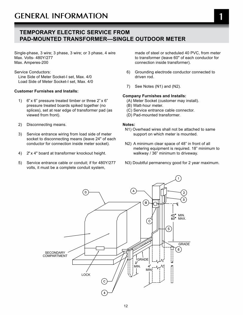
Single-phase, 3 wire; 3 phase, 3 wire; or 3 phase, 4 wireMax. Volts- 480Y/277Max. Amperes-200
Service Conductors:Line Side of Meter Socket-I set, Max. 4/0Load Side of Meter Socket-I set, Max. 4/0
Customer Furnishes and Installs:
1) 6” x 6” pressure treated timber or three 2” x 6” pressure treated boards spiked together (no splices), set at rear edge of transformer pad (as viewed from front).
2) Disconnecting means.
3) Service entrance wiring from load side of meter socket to disconnecting means (leave 24" of each conductor for connection inside meter socket).
4) 2" x 4" board at transformer knockout height.
5) Service entrance cable or conduit; if for 480Y/277 volts, it must be a complete conduit system,
made of steel or scheduled 40 PVC, from meter to transformer (leave 60" of each conductor for connection inside transformer).
6) Grounding electrode conductor connected to driven rod.
7) See Notes (N1) and (N2).
Company Furnishes and Installs:(A) Meter Socket (customer may install).(B) Watt-hour meter.(C) Service entrance cable connector.(D) Pad-mounted transformer.
Notes:N1) Overhead wires shall not be attached to same
support on which meter is mounted.
N2) A minimum clear space of 48” in front of all metering equipment is required. 18” minimum to walkway / 36” minimum to driveway.
N3) Doubtful permanency good for 2 year maximum.
SECONDARYCOMPARTMENT
LOCK
MIN.MIN.
MIN.MAX.
GRADE
GRADE
TEMPORARY ELECTRIC SERVICE FROM PAD-MOUNTED TRANSFORMER—SINGLE OUTDOOR METER
13
GENERAL INFORmATION 1
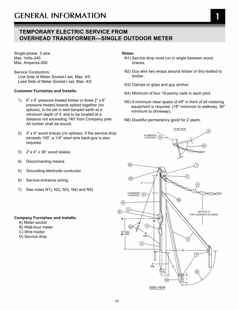
Single-phase, 3 wireMax. Volts-240Max. Amperes-200
Service Conductors:Line Side of Meter Socket-I set, Max. 4/0Load Side of Meter Socket-I set, Max. 4/0
Customer Furnishes and Installs:
1) 6” x 6” pressure treated timber or three 2” x 6” pressure treated boards spiked together (no splices), to be set in well-tamped earth at a minimum depth of 4’ and to be located at a distance not exceeding 140’ from Company pole. All lumber shall be sound.
2) 2” x 4” wood braces (no splices). If the service drop exceeds 100', a 1/4" steel wire back-guy is also required.
3) 2” x 4” x 36” wood stakes.
4) Disconnecting means.
5) Grounding electrode conductor.
6) Service entrance wiring.
7) See notes N1), N2), N3), N4) and N5).
Company Furnishes and Installs: A) Meter socket B) Watt-hour meter C) Wire holder D) Service drop
Notes:N1) Service drop must run in angle between wood braces.
N2) Guy wire two wraps around timber or thru-bolted to timber.
N3) Clamps or grips and guy anchor.
N4) Minimum of four 16-penny nails in each joint.
N5) A minimum clear space of 48" in front of all metering equipment is required. (18" minimum to walkway, 36" minimum to driveway).
N6) Doubtful permanency good for 2 years.
SEE PAGE 14FOR CLEARANCE TO GRADE
ALTERNATELOCATION
PLAN VIEW
ALTERNATELOCATION
SIDE VIEW
MIN.MIN.
MIN.
MIN.
N1
N2
N3
N4
N3
N1
N4
TEMPORARY ELECTRIC SERVICE FROM OVERHEAD TRANSFORMER—SINGLE OUTDOOR METER

14 15
GENERAL INFORmATION 1
NOTE G
NOTE BNOTE A
NOTE C
NOTE D
NOTE E
NOTE F
DRIVEWAY
STREET
BOTTOM OF SERVICE HEAD MUST BE HIGHER THAN LOOP WIRE AT BUILDING.
WHERE IT IS NECESSARY TO PLACE THE HOUSE BRACKET OR WIRE HOLDERS AT AN ELEVATION ABOVE THE CUSTOMER’S SERVICE HEAD, SUFFICIENT LOOP WIRE MUST BE ALLOWED TO CONNECT THE CUSTOMER’S SERVICE WIRES TO THE LOOP BOTTOM OF THE DRIP LOOP. CONNECTORS ON THE COVERED WIRE MUST BE TAPED.
WIRE HOLDER (BRACKET) FURNISHED AND INSTALLED BY COMPANY.
(A) The height of the service loop attachment must be of sufficient height to provide the required loop clearances listed below. On two story semi-attached and row houses, the point of attachment must be above the second floor windows. Where both single and three phase service loops are present, the clearance requirements must be maintained from the three phase loop, which occupies the lower position.
(B) 10' minimum vertical clearance for service loops crossing over decks, platforms or projections.
(C) Lawns and walkways subject to pedestrian traffic only must maintain a minimum clearance of 12' 0". (open wire) and 12' 0". (multiplex).
(D) Over a readily accessible roof, open wire and triplex loops must maintain a minimum clearance of 11' 6" (open wire) and 11' 0" in (multiplex). Open wire loops must maintain a minimum vertical clearance of 10 ft.-6 in. over an inaccessible roof. Multiplex loops may have a clearance of 3' 6" over an inaccessible roof.
A roof or balcony is considered readily accessible if it can be casually accessed through a doorway, ramp, window, stairway, or permanently mounted ladder. A permanently mounted ladder is not accessible if the bottom rung is 8' or more above the ground or other
permanently mounted surface. A roof or balcony is inaccessible if a person exerts extraordinary effort or employs tools to gain entry.
(E) Above residential driveways, a clearance of 16' 6" (open wire) and 16 ft.-0 in (multiplex) must be maintained. The clearance may be reduced to 12' 6" where the height of the building does not permit the loop to meet the initial open wire and multiplex requirement.
(F) Above streets, alleys, parking lots, etc, a clearance of 16' 6" (open wire) and 16' 0" (multiplex) must be maintained.
(G) A 3' clearance must be maintained in any direction from windows, doors, porches and fire escapes, or similar locations. 120/240 v single phase, 120/208 v three phase, and 277/480 v three phase multiplex loops are exempt from this requirement when installed above the top of window. The 3' requirement does not apply to service loops installed along side of windows that are not designed to open.
SERVICE DROP CLEARANCES FOR RESIDENTIAL AND COMMERCIAL PROPERTIES
Notes:

15
GENERAL INFORmATION 1
SMALL GENERATOR INTERCONNECTIONS
Small generators, especially those powered by renewable sources, are an essential part of Maryland’s energy supply needs. Examples of Small Generator Interconnection equipment include:
• Wind turbines• Photo voltaics (PV)• Micro-turbines• Small gas-turbine generators• Fuel cells• Solar panels• Small internal combustion-engine generators
(ICE)• Small steam turbine units (cogeneration)
More and more customers are supplementing their power supply with small generator equipment. Some residential customers simply want to have back-up power in the event of an outage. Others (mostly industrial and commercial customers) want to ensure power reliability or sell the power they generate to others on the power grid.
Small Generator Interconnection is a general name for the process of registering and connecting small-scale power generation equipment to BGE’s electric utility distribution system.
Effective June 9, 2008, the Maryland Public Service Commission (MD PSC) requires that all Small Generator Interconnection equipment that is/will be connected to BGE’s electric utility distribution system be approved by BGE pursuant to the requirements of Section 20.50.09 of the Code of Maryland Regulations.
The regulations ensure that all persons or entities in the State of Maryland who want to install generators up to 10,000 kW (which will be connected for normal operation to an electric utility distribution system in Maryland) now have a consistent way of applying to BGE for interconnection using standard application forms, fees and processes.
The regulations apply to:
All types of residential, industrial and commercial small generation resources which include, but are not limited to, generation technologies connected to an electric utility distribution system (such as internal combustion engine generators, cogeneration steam turbines, gas turbines, wind turbines, solar cells, fuel cells, micro-turbines and combined heat and power systems).
The regulations do not apply to:
Residential or small-scale back-up emergency generators which only start when power is lost (and are never connected to an electric utility distribution system) or if the generator operates in such a way that it is never connected to an electric utility distribution system for more than 100 milliseconds.
Generally speaking, customers with residential small generator equipment that is not connected to the power grid are not required to apply to BGE for approval to interconnect. Similarly, customers with back-up generators only used during outages (for 100 milliseconds or less) do not need to apply.
For more information and to apply for interconnection, visit us at bge.com.

16 17
2
PADmOUNTED EqUIPmENT INFORmATION
17
PADmOUNTED EqUIPmENT INFORmATION 2
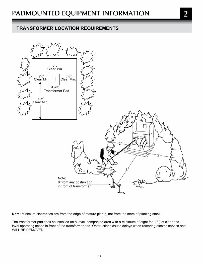
TRANSFORMER LOCATION REQUIREMENTS
Note: Minimum clearances are from the edge of mature plants, not from the stem of planting stock. The transformer pad shall be installed on a level, compacted area with a minimum of eight feet (8’) of clear and level operating space in front of the transformer pad. Obstructions cause delays when restoring electric service and WILL BE REMOVED.
Clear Min.
8’-0”
2’-0”
2’-0”
l
2’-0”
l(Front)
T
Clear Min.
Clear Min.
Clear Min.
Transformer Pad
Note:8’ from any obstruction in front of transformer
18 19
TRANSFORMER LOCATION REQUIREMENTS (CONT'D)
PADmOUNTED EqUIPmENT INFORmATION 2
General Transformer Location Requirements
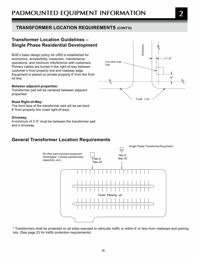
Transformer Location Guidelines – Single Phase Residential Development
BGE’s basic design policy for URD is established for economics, accessibility, inspection, maintenance, operations, and minimum interference with customers. Primary cables are buried in the right-of-way between customer’s front property line and roadway edge. Equipment is placed on private property 6' from the front lot line.
Between adjacent properties:Transformer pad will be centered between adjacent properties.
Road Right-of-Way:The front face of the transformer pad will be set back 6' from property line (road right-of-way).
Driveway:A minimum of 3’ 6” must be between the transformer pad and a driveway.
* Transformers shall be protected on all sides exposed to vehicular traffic or within 8' or less from roadways and parking lots. (See page 23 for traffic protection requirements).
Single Phase Transformer/Equipment
*Min 8’Max 20’
*Min 8’Max 30’
All other pad-mounted equipment (Switchgear, 3 phase transformers, capacitors, etc.)
19
PADmOUNTED EqUIPmENT INFORmATION 2
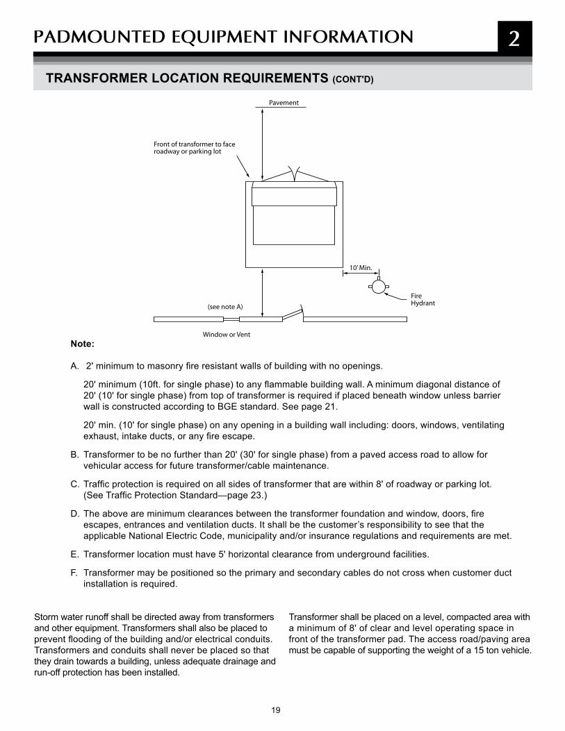
Note:
A. 2' minimum to masonry fire resistant walls of building with no openings.
20' minimum (10ft. for single phase) to any flammable building wall. A minimum diagonal distance of 20' (10' for single phase) from top of transformer is required if placed beneath window unless barrier wall is constructed according to BGE standard. See page 21.
20' min. (10' for single phase) on any opening in a building wall including: doors, windows, ventilating exhaust, intake ducts, or any fire escape.
B. Transformer to be no further than 20' (30' for single phase) from a paved access road to allow for vehicular access for future transformer/cable maintenance.
C. Traffic protection is required on all sides of transformer that are within 8' of roadway or parking lot. (See Traffic Protection Standard—page 23.)
D. The above are minimum clearances between the transformer foundation and window, doors, fire escapes, entrances and ventilation ducts. It shall be the customer’s responsibility to see that the applicable National Electric Code, municipality and/or insurance regulations and requirements are met.
E. Transformer location must have 5' horizontal clearance from underground facilities.
F. Transformer may be positioned so the primary and secondary cables do not cross when customer duct installation is required.
Storm water runoff shall be directed away from transformers and other equipment. Transformers shall also be placed to prevent flooding of the building and/or electrical conduits. Transformers and conduits shall never be placed so that they drain towards a building, unless adequate drainage and run-off protection has been installed.
Transformer shall be placed on a level, compacted area with a minimum of 8' of clear and level operating space in front of the transformer pad. The access road/paving area must be capable of supporting the weight of a 15 ton vehicle.
Pavement
10’ Min.
FireHydrant(see note A)
Window or Vent
Front of transformer to face roadway or parking lot
TRANSFORMER LOCATION REQUIREMENTS (CONT'D)
20 21
PADmOUNTED EqUIPmENT INFORmATION 2
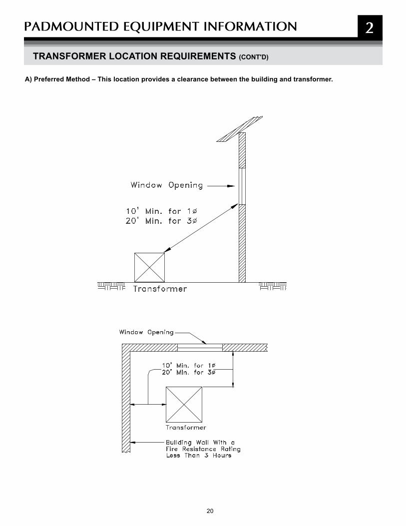
A) Preferred Method – This location provides a clearance between the building and transformer.
TRANSFORMER LOCATION REQUIREMENTS (CONT'D)
21
PADmOUNTED EqUIPmENT INFORmATION 2
TRANSFORMER LOCATION REQUIREMENTS (CONT'D)
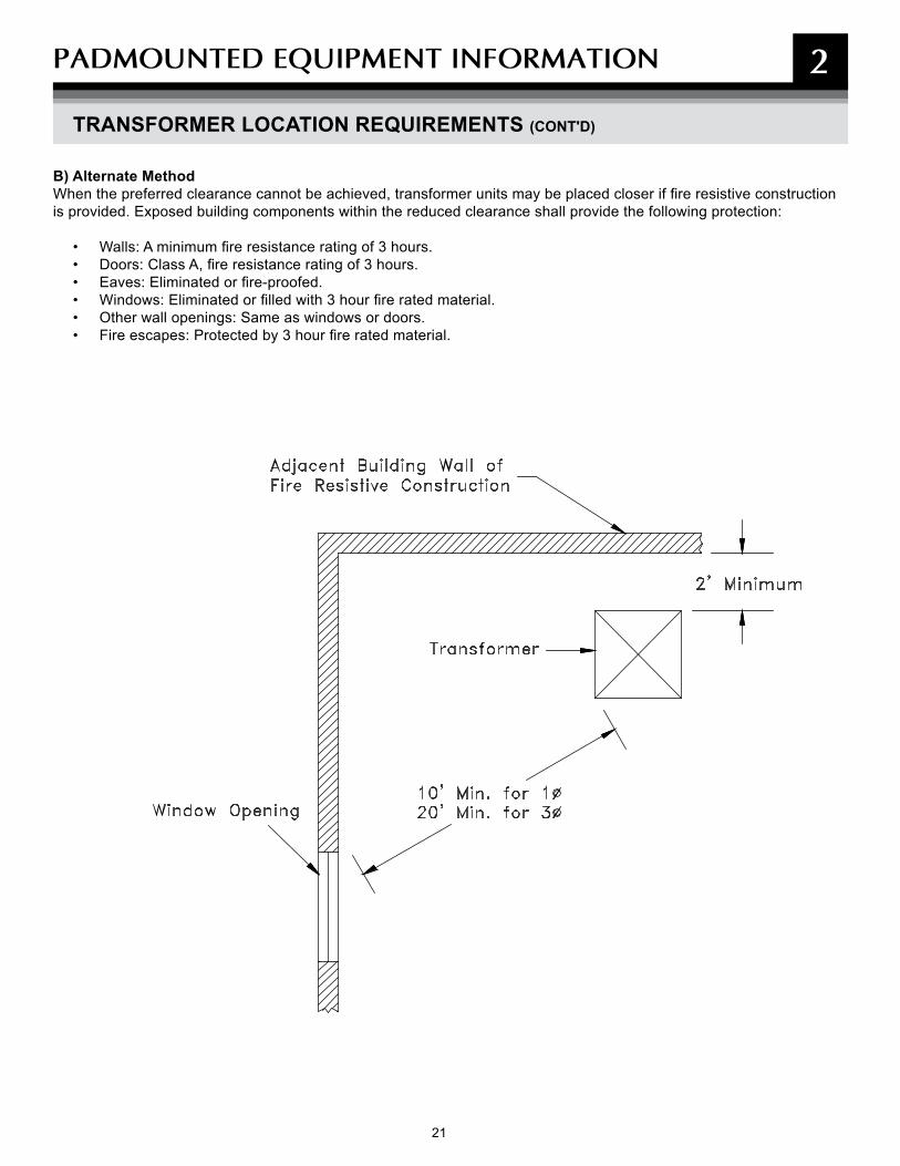
B) Alternate MethodWhen the preferred clearance cannot be achieved, transformer units may be placed closer if fire resistive construction is provided. Exposed building components within the reduced clearance shall provide the following protection:
• Walls: A minimum fire resistance rating of 3 hours.• Doors: Class A, fire resistance rating of 3 hours.• Eaves: Eliminated or fire-proofed.• Windows: Eliminated or filled with 3 hour fire rated material.• Other wall openings: Same as windows or doors.• Fire escapes: Protected by 3 hour fire rated material.
22 23
PADmOUNTED EqUIPmENT INFORmATION
TRANSFORMER LOCATION REQUIREMENTS (CONT'D)
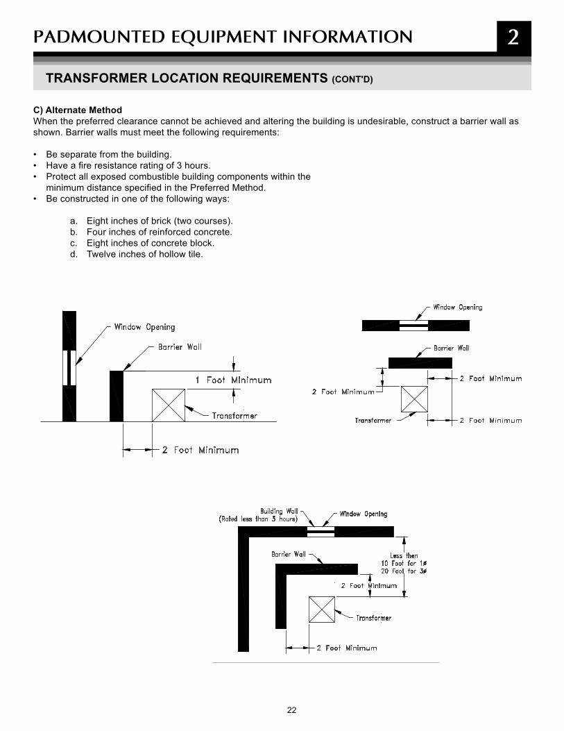
C) Alternate MethodWhen the preferred clearance cannot be achieved and altering the building is undesirable, construct a barrier wall as shown. Barrier walls must meet the following requirements:
• Be separate from the building.• Have a fire resistance rating of 3 hours.• Protect all exposed combustible building components within the
minimum distance specified in the Preferred Method.• Be constructed in one of the following ways:
a. Eight inches of brick (two courses).b. Four inches of reinforced concrete.c. Eight inches of concrete block.d. Twelve inches of hollow tile.
2
23
PADmOUNTED EqUIPmENT INFORmATION 2
TRAFFIC PROTECTION FOR PAD-MOUNTED TRANSFORMERS
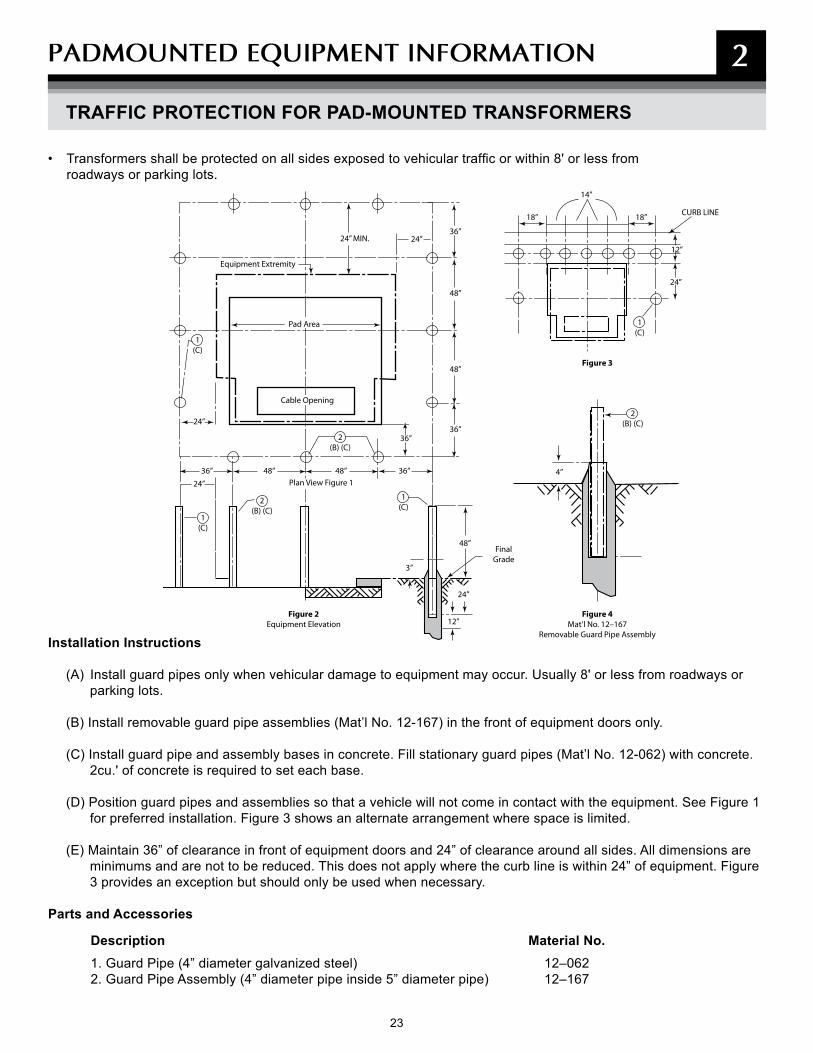
• Transformers shall be protected on all sides exposed to vehicular traffic or within 8' or less from roadways or parking lots.
Installation Instructions
(A) Install guard pipes only when vehicular damage to equipment may occur. Usually 8' or less from roadways or parking lots.
(B) Install removable guard pipe assemblies (Mat’l No. 12-167) in the front of equipment doors only.
(C) Install guard pipe and assembly bases in concrete. Fill stationary guard pipes (Mat’l No. 12-062) with concrete. 2cu.' of concrete is required to set each base.
(D) Position guard pipes and assemblies so that a vehicle will not come in contact with the equipment. See Figure 1 for preferred installation. Figure 3 shows an alternate arrangement where space is limited.
(E) Maintain 36” of clearance in front of equipment doors and 24” of clearance around all sides. All dimensions are minimums and are not to be reduced. This does not apply where the curb line is within 24” of equipment. Figure 3 provides an exception but should only be used when necessary.
Parts and Accessories
Description Material No. 1. Guard Pipe (4” diameter galvanized steel) 12–062 2. Guard Pipe Assembly (4” diameter pipe inside 5” diameter pipe) 12–167
14”
18” 18”
Figure 4Mat’l No. 12–167
Removable Guard Pipe Assembly
Figure 2Equipment Elevation
Final Grade
Plan View Figure 1
Cable Opening
Pad Area
Equipment Extremity
CURB LINE
24” MIN. 24”
24”
24”
24”
24”
3”
4”
2 (B) (C)
2 (B) (C)
2 (B) (C)
1(C)
1(C)
1(C)
1(C)
12”
12”
36”
36” 36”
36” 36”
48”
48”
48”
48” 48”
Figure 3
24 25
PADmOUNTED EqUIPmENT INFORmATION 2
TRANSFORMER PAD SPECIFICATIONS
• Customers are responsible for purchasing and installing the transformer pads for three-phase transformers. Pre-cast concrete transformer pads can be purchased and delivered to your site from BGE’s Contractor Supplier (See page 28).
• Two different pads are available:– BGE Material No. 12-668 for use with transformers
500 kVA and smaller.– BGE Material No. 12-790 for use with transformers
750 kVA and above.
• The dimensions of those pads are shown on page 25. BGE will provide the required pad size for each job.
• BGE allows “pour in place” transformer pads, in accordance with specifications on page 25 and should have two conduits provided for cables in all cases.
Note: A sump may be required under transformers that contain more than 300 gallons of oil (750 kVA or larger). The 40’ diameter sump (to 72” below grade) is required if the final grades will slope towards an adjacent building.
This is especially true if the area around the transformer is to be paved and drains installed. Contact the BGE Representative for the project to determine the final details of design and construction.
• The front of the transformer pad should be placed in such a way as to prevent the crossing of primary and service ducts. This simplifies the installation and maintenance of conduits.
• The pad shall be installed on a level area with a minimum of 8 feet of clear and level operating space in front of the transformer pad. BGE is responsible for the grounding of the transformer pad.
• The customer shall install the ground rod when the pad is installed on the site. If no space is being left in the pad opening, a PVC duct shall be installed to exit the pad side to allow for a grounding connection.
• If the duct count exceeds nine, the ducts shall be banded together within the transformer pad cutout to ensure all ducts remain in their correct spaces within the transformer. (See page 47).
25
PADmOUNTED EqUIPmENT INFORmATION
TRANSFORMER PAD SPECIFICATIONS (CONT'D)
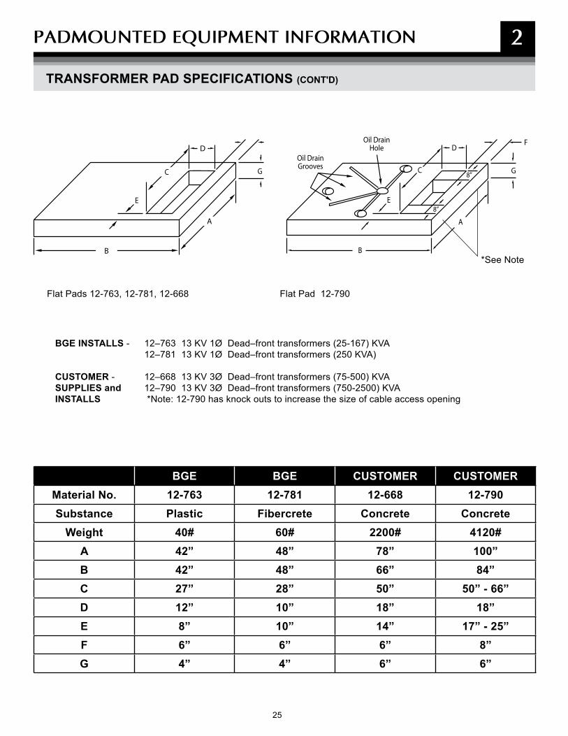
Flat Pads 12-763, 12-781, 12-668 Flat Pad 12-790
BGE INSTALLS - 12–763 13 KV 1Ø Dead–front transformers (25-167) KVA 12–781 13 KV 1Ø Dead–front transformers (250 KVA)
CUSTOMER - 12–668 13 KV 3Ø Dead–front transformers (75-500) KVASUPPLIES and 12–790 13 KV 3Ø Dead–front transformers (750-2500) KVAINSTALLS *Note: 12-790 has knock outs to increase the size of cable access opening
BGE BGE CUSTOMER CUSTOMERMaterial No. 12-763 12-781 12-668 12-790Substance Plastic Fibercrete Concrete Concrete
Weight 40# 60# 2200# 4120#A 42” 48” 78” 100”B 42” 48” 66” 84”C 27” 28” 50” 50” - 66”D 12” 10” 18” 18”E 8” 10” 14” 17” - 25”F 6” 6” 6” 8”G 4” 4” 6” 6”
B
E
C G
E
Oil DrainGrooves
Oil DrainHoleD
A
F
G
A
8”
8”C
B
D
*See Note
2
26 27
PADmOUNTED EqUIPmENT INFORmATION
BGE PAD-MOUNTED SWITCHGEAR LOCATION REQUIREMENTS
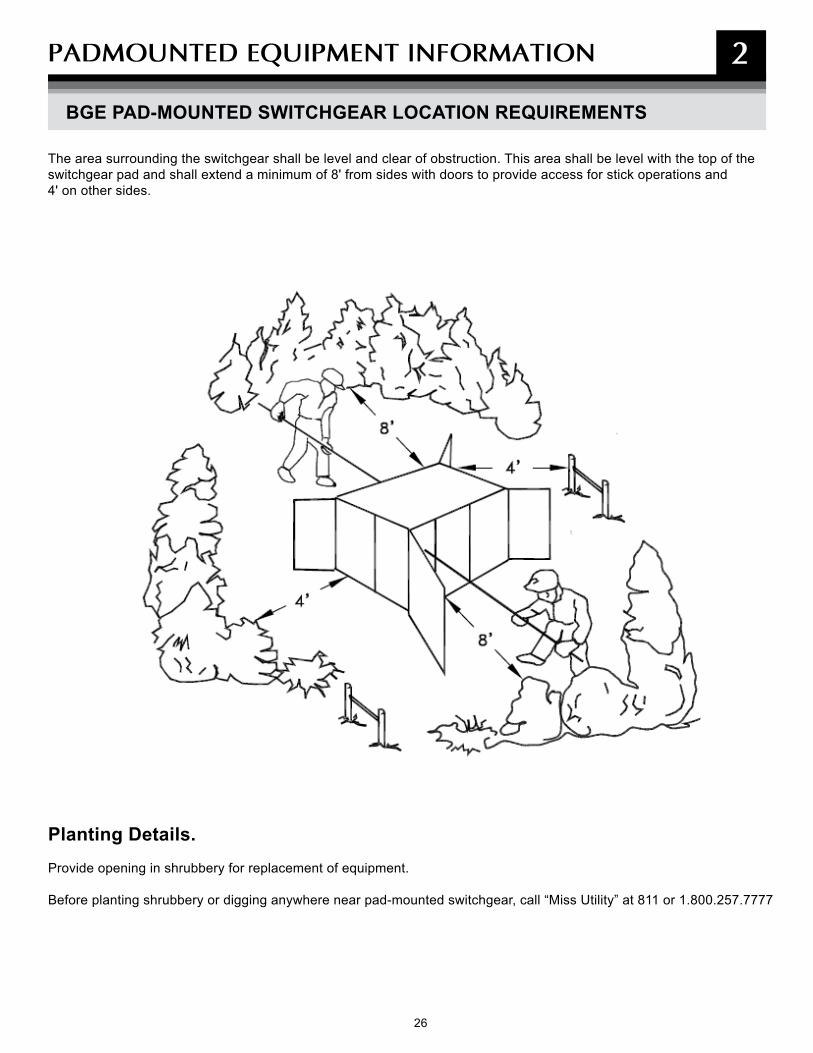
The area surrounding the switchgear shall be level and clear of obstruction. This area shall be level with the top of the switchgear pad and shall extend a minimum of 8' from sides with doors to provide access for stick operations and 4' on other sides.
Planting Details.Provide opening in shrubbery for replacement of equipment.
Before planting shrubbery or digging anywhere near pad-mounted switchgear, call “Miss Utility” at 811 or 1.800.257.7777
2
27
PADmOUNTED EqUIPmENT INFORmATION 2
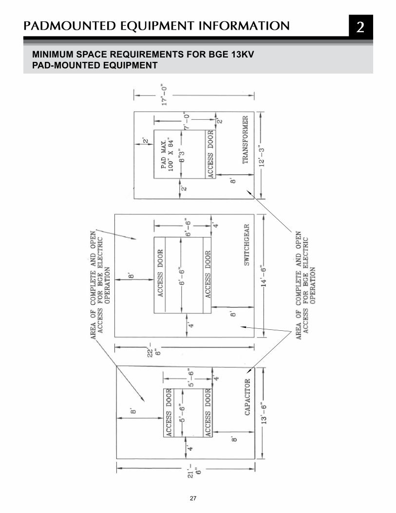
MINIMUM SPACE REQUIREMENTS FOR BGE 13KV PAD-MOUNTED EQUIPMENT

29 29
PADmOUNTED EqUIPmENT INFORmATION
MATERIALS AVAILABLE FROM BGE CONTRACTOR SUPPLIER
In order to make materials available and as easy as possible for you to obtain, the following materials are available for purchase through BGE’s Contractor supplier:
• Pad, Precast, Concrete 78 In. X 66 In. • Pad, Precast, Concrete 100 In. X 84 In. • Guard, Pipe 4 Inchs Std Galvanized• Guard, Removable Pipe Assembly• Tape, Marking, 3 In. Wide X 1000 Ft. • Cover, Manhole, 36 Inch• Frame, 6" Deep, Roadway, Used With 36'' Dia. Cover• Box, Splice, 15 KV• Box, Splice, 35 KV• BOX, SPLICING, 600 V, 16''W X 22"L X 30"D• Enclosure, Below Grade 600 V, 12"W X 12''L X 17''D • Enclosure, Below Grade 600 V, 20''W X 30''L X 16''D • Rod Ground• Box, Splice 15KV 30'' X 60'' X 36'' Deep• Pad Plastic Flat 42''x42''x4''• Pad Box 15KV For Pme Air Swgear • Gas Marking Tape
These materials are available by contacting: Choctaw-Kaul Distribution [email protected]
Direct on site delivery.
Variety of payment options are available.
All costs are fully disclosed and are subject to change without notice.
28
2

29 29
NOTEs

30 31
3
COmmERCIAL &INDUsTRIAL
30

31
COmmERCIAL & INDUsTRIAL 3
The procedures and specifications in this section apply to Commercial and Industrial projects which include the following:
• New commercial and non-residential building.
• Apartments or condominiums.
• Barns or garages on residential or commercial property.
• Service increases to existing commercial or non-residential building.
• Traffic signals, CATV power supplies, cell sites or traffic cameras.
• Relocation/removal of existing BGE non-residential facilities.
• Temporary service for commercial and industrial projects including apartments and condominiums.

32 33
COmmERCIAL & INDUsTRIAL 3
CONDITIONS OF ELECTRIC SUPPLY
Customer electrical loads are to be balanced in such a way that the imbalance between any two phases or legs is less than 10 percent. (Reference BGE Service Tariff sections 9.121 and 9.132. Customer‘s equipment has been significantly damaged by severe load imbalances.)
Electric Service Supply Points• BGE will supply one service connection:
a. For all the requirements of a single property when the supply is for a group of buildings, the supply point is located, wherever practicable, at a location central to the group. (A central service and meter location is required for flex office and warehouse buildings.)
b. For any separate building of a group, provided such service is for the entire requirements of that building.
c. For any separate building occupied by one or more customers.
• All commercial building structures less than 300 feet long require a single service point for meter installations, except for strip commercial building, which BGE will design on a case-by-case basis.
• Where practicable, a single loop will be provided for a pair of adjoining buildings.
• BGE will supply one meter installation for all requirements of each customer at each supply point:
a. Where two or more customers are supplied from one service connection, a centralized meter location is required wherever practicable.
b. Each meter installation must have a separate application of the rate schedule.
• BGE provides and considers as “one service connection” and as “one meter installation”:
a. The combination of single-phase and three-phase services.
b. Two or more service connections of the same characteristics where required for a single customer by reason of the size of the load (such as a lighting load in excess of the capacity of one phase distribution) or by reason of the character of the load (such as welders and X-rays where a combination on the same service with lighting is impracticable).
Note: Totalization of meters may be required. Customer charges apply.
All electric facility installation, lines, and equipment, must conform to the latest edition of the BGE Gas & Electric Metering Manual available under the New Construction Services section on bge.com.
Builder/Developer/Customer Responsibilities• Submit your completed Service Application as early as
possible in your planning process.
• Provide on premise, without charge, suitable space and supporting structure acceptable to BGE for metering and service equipment. BGE will approve compartments in switchgear to building metering instrument transformers, unmetered service equipment, or cable termination facilities.
• All service equipment other than that specifically stated is furnished, installed, and maintained by you (or the owner), including the service entrance, the service switch or circuit breaker (including the wiring to BGE’s metering equipment where the service switch or circuit breaker is located on the line side of the meter), and any protective equipment required on your distribution system. Where other than a self-contained meter is required, you provide the raceway between BGE’s instrument transformers and the meter.
• Where you elect to furnish and install prefabricated multi-meter socket assemblies, install approved devices. BGE will provide a list of approved devices. Connections will not be made to a device that has not been approved prior to its installation.
• Furnish and install a conduit bank for secondary cable (< 600V) from termination point to transformer pad, concrete-encased if required by BGE.
• Furnish and install a conduit bank for primary cables (> 600V) under paving or improved areas as required by BGE or any city/county regulations, concrete-encased, if required by BGE or any city/county regulations.
• Where applicable, provide suitable meter protection meeting approved BGE specifications at your cost.
• Furnish and install pull boxes or manholes for secondary duct bank if necessary due to the number of bends needed for the selected route.
33
COmmERCIAL & INDUsTRIAL 3
CONDITIONS OF ELECTRIC SUPPLY (CONT'D)
• Purchase/construct and install transformer pad(s) for three-phase transformers only. (See page 25).
• Install warning tape over conduit bank.
• Provide transformer vaults and manholes if required.
• Provide certificate of approval from local jurisdiction or authorized inspection agency to verify conformance. The job will not be released to construction until this is received.
• Baltimore City duct system privilege permits and the associated customer duct construction are the responsibility of the customer. BGE is not an agent. Lack of the proper permit may delay BGE construction.
BGE Responsibilities• Contact the customer within 10 days of our receipt of
the completed Service Application.
• Conduct initial site visit for planning and designing the job.
• Install electric service per extension/relocation contract or gas service sketch.
• Furnish and install the transformers required to step down to secondary distribution system voltage and regulators required on BGE’s distribution system. BGE also furnishes and maintains and, if practicable, installs its meter connection device.
• Furnish and install secondary cables in customer or Baltimore City DPW conduit.
• Terminate and energize all BGE cables.
• Furnish and install all meters after receipt of certificate of approval from the jurisdictional authority for both gas and electric.
• Install BGE’s transformers and appurtenant equipment for general distribution purposes, which normally are located on poles in streets, alleys, and lot lines or on ground level pads adjacent to lot lines, or in manholes or vaults in the street or sidewalk in cable and conduit areas. Where these facilities are necessary solely for your service requirements, they normally are located on your premises.
• Furnish and install single phase transformer pads.
Local Jurisdiction Responsibilities• Upon application by the licensed electrician, issue
the appropriate permit for the installation of customer wiring and equipment, if applicable.
• Inspect and approve customer’s wiring and equipment.
• Provide BGE with certificate of approval notification for customer’s wiring and equipment.
Electrical Service Entrance— Service at Secondary Distribution Systems Voltages• The service switch or circuit breaker must be installed
on the load side of the meter, except where the jurisdictional authority requires it to be installed on the line side. Where the installation is on the line side, the service switch or circuit breaker must be so designed that the unmetered wiring is inaccessible without breaking the seal, even during the renewal of switch fuses. Fusible disconnects of the pullout type are acceptable only where specifically approved by BGE.
• You must also provide on premise, without charge, space (including a vault, if required) satisfactory to BGE for the transformers and equipment necessary for your service.
Transformer Vaults• If BGE requires a vault on premise, you must provide one.
Overhead Electrical Service Entrance Location• Service entrances must be located such that the
service drop wires and service head are out of reach from doors, windows, porches, and the like.
• Service entrances for adjoining houses must, where practicable, be arranged such that each service drop will supply two houses. Where such houses have an area way between them, the service entrance must be located on the rear wall.
• In the event it becomes necessary to change the service entrance wiring, the service entrance location must conform to these requirements.
34 35
COmmERCIAL & INDUsTRIAL 3
CONDITIONS OF ELECTRIC SUPPLY (CONT'D)
Electrical Service Drop (or Loop) Attachment• Brackets for the attachment of the service drop (the
wire span to your building) are installed by BGE at a point meeting the drop clearance required by the inspection authority having jurisdiction. In addition, this point of attachment must be readily accessible to BGE at all times and must be sufficient to withstand the maximum pull for the required service drop.
• Where porches, awnings, or other obstructions render the point of attachment to a building inaccessible by extension ladder for installation and maintenance, suitable provisions for attaching the drop at a location accessible by extension ladder (and usually at the outer edge of these obstructions) must be provided by you.
• On multiple-story buildings, the point of attachment must be above the second floor windows.
• Where additions or alterations to a building render the point of attachment inaccessible, you must, at your expense, relocate the service entrance wiring and provide suitable means for supporting the drop.
Support Structure for Electrical Service Drop• Mast on low building: Where the building is of
insufficient height to provide the required clearance for the service drop, it’s your responsibility to provide and bolt to the building a mast of the proper length, clearance, and strength.
• Free-standing pole or timber: Where there are circumstances that do not permit the connection of a drop directly to your building, or there is otherwise insufficient support, or there is no building to which the drop may be connected, you must provide and erect a suitable pole or structure. This suitable structure must be in accordance with BGE’s layout. It must be the proper length to provide the required clearance for the drop and of sufficient size for the load. The point of BGE’s service connection to the customer-owned pole or structure is the load-end of the pole.
Overhead Electrical Service Entrance Conductors• Between the point of attachment of the service drop
and the meter, the conductors must be installed:
a. As service entrance cable, b. In rigid metal conduit, or c. In electrical metallic tubing. Except that, on
multiple meter installations, the horizontal runs of unmetered wiring beneath the meters must be installed in sealable wire troughs.
• A suitable service head must be provided and the conductors must extend beyond the service head sufficiently to enable BGE to make connections to the service drop.
• Where, with indoor metering, the length of service entrance cable inside the building is more than 5 feet, you must enclose it in rigid or flexible metal conduit, electrical metallic tubing, or a sealable wire from the point of entry into the building to the point of attachment to the meter connection devices.
For more details about overhead electric services, see the BGE Gas & Electric Metering Manual under the New Construction Services section available at bge.com.

35
COmmERCIAL & INDUsTRIAL 3
ELECTRIC SERVICES AVAILABLE
*Limited availability. Please consult with your BGE Representative.
Service at Primary Systems Voltage: For service supplied at BGE’s primary voltages (13 kV or 33 kV), please consult with your BGE Representative for details or see Primary Service Requirements under the New Construction Services section available at bge.com.
Talk to us early. Consult with BGE concerning the characteristics and availability of electric service at a particular location before proceeding with plans for any installation, whether new, additional, replacement, or relocation.
Standard ServiceThe characteristics of standard service, namely, alternating current at 60 hertz, are as follows (voltages are nominal):
VOLTAGE NO. OF PHASES NO. OF CONDUCTORS NOTES
120 1 2 1
120/208 1 3 2
120/240 1 3 2
120/208 3 4 –
277/480 3 4 3
240* 3 3 4
NOTES:
1. Single-phase, two-wire, 120-volt service may be used only for the supply of an installation having not more than two 15-ampere, two-wire branch circuits, or for small fixed loads such as illuminated signs or traffic lights, provided the total connected load current (excluding motor starting currents, if any) does not exceed 20-amperes. The addition of a third circuit, or the alteration of wiring for the installation of an additional meter, requires a change to three-wire service. Service supplying any apartment or separate living quarters must be three-wire. (Exception: A single-phase, two-wire, 120-volt service installed prior to January 1, 1952 may be used for the supply of three, four, five or six circuits in a residence or individual apartment, only one of which circuits may be as large as 20-amperes; but such two-wire service may not be used for the supply of an aggregate room air cooler capacity requiring more than 15-amperes running current. In the event of a replacement at any time of service entrance cable or conduit, a change to three-wire service and compliance with the provisions of Note 2 is required; existing conduit may be rewired.)
2. Single-phase, three-wire service may be used for the supply of a service not exceeding 60-amperes when served from the Network Secondary Distribution System. Location on the system of the point to be supplied and other conditions affect the permissibility of a service in excess of 200-amperes when served beyond the Network Secondary Distribution System. The wiring for each service must be so arranged that the loads connected to each outside leg and neutral are equal or within a balance of one circuit either way. Where more than one such service is required, the load must be balanced over the phases, as equally as commercial practice will permit.
3. Used where your connected load exceeds 150 kW, or where otherwise approved by BGE.
4. When your location is beyond BGE’s Network Secondary Distribution System, you may use this service. However, it is restricted to existing customer installations only. Use it in combination with single-phase service and as an alternative to these services:
120/208 volt, four-wire and 277/480 volt four-wire.

36 37
COmmERCIAL & INDUsTRIAL 3
• As the customer’s electric load increases, BGE will make appropriate alterations, if necessary, to its distribution system to provide for the increase.
• The extension charge, if any, for such work is determined as though the customer is newly taking service.
• You are responsible for indicating where all private infrastructures are located (sprinkler systems, electric dog fences, low-voltage garden lighting, etc.), and where we can dig test holes, and for clearing anything in the path of BGE’s construction.
Before installing motors or miscellaneous equipment, the Customer should consult the Company. It is important that the characteristics of motors, motor-starting equipment, and miscellaneous apparatus such as welders and X-rays, be such as not to impair the quality of service rendered by the Company to any of its Customers. The Company shall in any event be consulted prior to the preparation of plans for the installation of:
(a) A single-phase motor of 3 horsepower and larger. (b) A three-phase motor of 25 horsepower and larger.
(c) A motor requiring frequent starting.(d) A synchronous motor. (Motors of this type are
recommended for large installations for power factor correction.)
(e) A single-phase motor on a three-phase service. (f) Group-operated motors started automatically.
(Sequence starting may be required.)(g) Certain alternating current equipment such as
welders, X-rays, radio transmitters, rectifiers, signal systems and air condition9ing.
(h) Service at Primary Systems voltages.
If a motor requires a starting current higher than permissible, a starting device shall be used which will limit the starting current to the prescribed permissible value. The starter shall be provided with a no-voltage release mechanism to insure the return of the starter to the
starting position upon failure of voltage. A motor which can restart automatically after shutdown shall not be installed so that its automatic restarting can result in injury to persons or equipment.
INCREASE IN LOAD TO EXISTING CUSTOMERS (HEAVY-UP)
INSTALLATIONS REQUIRING SPECIAL CONSIDERATION
STARTING EQUIPMENT
37
COmmERCIAL & INDUsTRIAL 3
CONDITION OF GAS SUPPLY
All gas installation, lines, and equipment must conform to the latest edition of the BGE Gas & Electric Metering Manual under the New Construction Service section available at bge.com.
Builder/Developer/Customer Responsibilities• Complete the service application including gas load
information and required delivery pressure, such as Standard, 2 PSIG, or other as specified.
• Suitably mark location of gas service and meter assembly location per BGE specifications and approval.
• Provide BGE with a reasonable service date.• Install a concrete meter foundation pad, if required,
at your cost, according to BGE site and space requirements for the BGE gas metering assembly.
• Install on-site duct sleeves and buried warning tape as required by BGE for all natural gas infrastructures that will be installed in joint trench applications with the electric service. (Applicable only for plastic gas services sizes: 1/2-inch CTS; 3/4 inch IPS, 1 inch CTS; 1-1/4 inch CTS; 1-1/4 inch IPS and 2 inch IPS. No steel gas piping is allowed in conduit.)
• Install minimum 4 inch conduit and underground warning tape unless otherwise specified for natural gas service under paving, or under improved areas as required by BGE or any City or County regulations. (Applicable only for plastic gas services sizes: 1/2-inch CTS; 3/4 inch IPS ,1 inch CTS; 1-1/4 inch CTS; 1-1/4 inch IPS and 2 inch IPS. No steel gas piping is allowed in conduit.)
• Provide a certificate of approval from local jurisdiction or authorized inspection agency to verify conformance. The job will not be released to construction until this is received.
• Notify BGE when the site is within six inches of grade and ready for BGE equipment installation.
• Where applicable, provide BGE-approved meter protection at your cost.
BGE Responsibilities• Contact the customer within 10 days of receipt of the
completed service application.• Verify receipt of a signed customer contract for
gas service.• Conduct a pre-site inspection, if necessary.• Confirm delivery pressure (Standard, 2 PSIG, or other
as specified) from the certificate of approval, if available.• Install gas service per customer service agreement or
gas service sketch, complete the necessary test, and leak check on the service.
• After certificate of approval has been received from the local jurisdictional authority, schedule gas meter assembly for installation.
• Set the meter and provide gas up to the Customer’s main gas valve.
• Leave the Customer’s main gas valve in the “off” position and plug/cap/blank the point of service connection outlet and conduct a PSC leak test.
• Complete the new gas service tag, which notifies the customer to call the licensed plumber to introduce gas into the fuel line.
Licensed Plumber Responsibilities• Obtain all permits for customer’s gas piping and
equipment.• Install, inspect, and test new customer piping and
equipment in accordance with the National Fuel Gas Code and/or any requirements of the local jurisdiction having authority.
• Obtain all certificates of approval for customer’s gas piping and equipment, then contact BGE to verify receipt of the certificates.
• Upon the completion of the meter assembly, remove plug at the outlet of the Customer’s main gas valve and connect the customer’s fuel line.
• For multi-meter manifold installations, verify customer fuel lines.
• Open the Customer’s main gas valve and introduce gas into the fuel line.
• Test for leakage of the piping, equipment, connections, and valves using gas supplied at its supply pressure per the National Fuel Gas Code and/or any requirements of the local jurisdiction having authority.
• Place all gas equipment in operation in accordance with manufacturers’ instructions and specifications, and the National Fuel Gas Code and/or any requirements of the local jurisdiction having authority.
Local Jurisdiction Responsibilities• Inspect and approve the customer’s gas piping and
equipment.• Provide BGE with certificate of approval notification from
local jurisdiction for customer’s fuel lines.
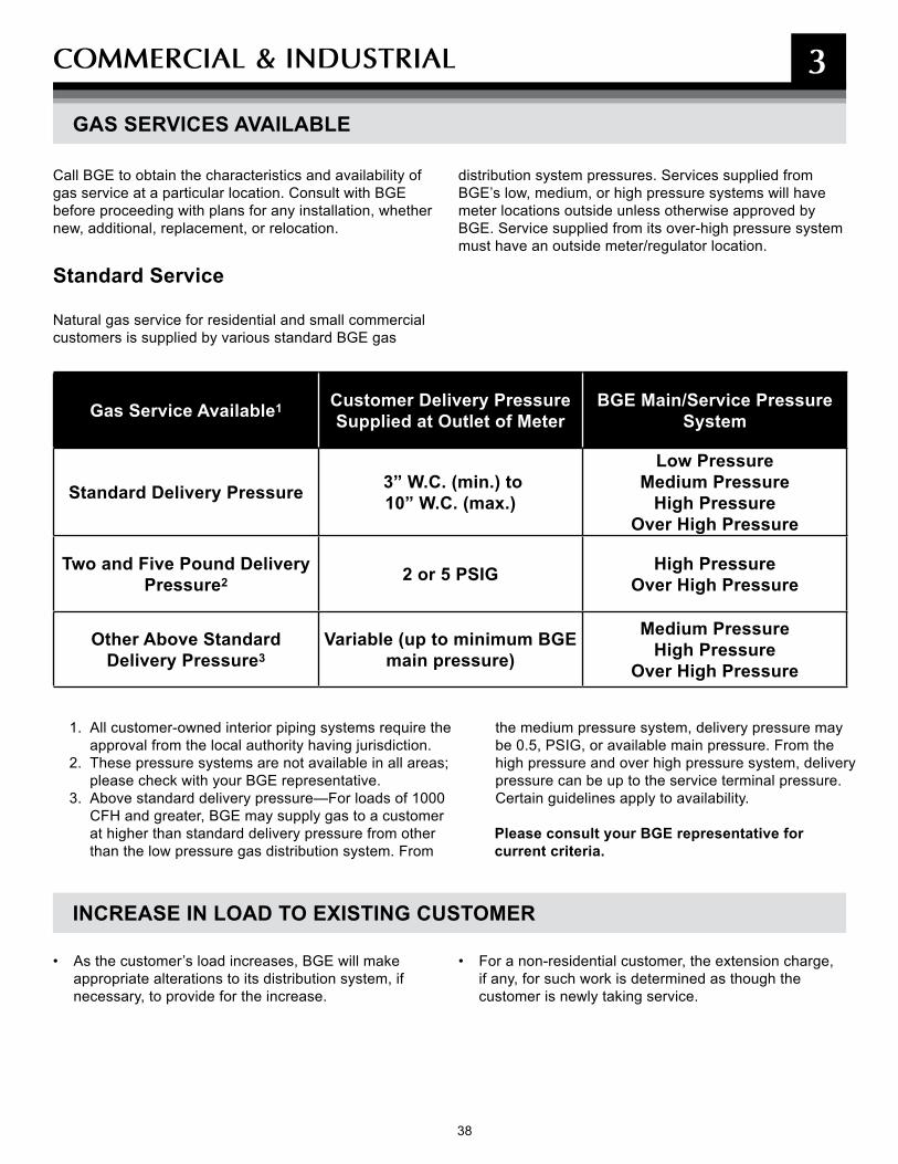
38 39
COmmERCIAL & INDUsTRIAL 3
GAS SERVICES AVAILABLE
Gas Service Available1 Customer Delivery Pressure Supplied at Outlet of Meter
BGE Main/Service Pressure System
Standard Delivery Pressure 3” W.C. (min.) to 10” W.C. (max.)
Low Pressure Medium Pressure
High Pressure Over High Pressure
Two and Five Pound Delivery Pressure2 2 or 5 PSIG High Pressure
Over High Pressure
Other Above Standard Delivery Pressure3
Variable (up to minimum BGE main pressure)
Medium Pressure High Pressure
Over High Pressure
1. All customer-owned interior piping systems require the approval from the local authority having jurisdiction.
2. These pressure systems are not available in all areas; please check with your BGE representative.
3. Above standard delivery pressure—For loads of 1000 CFH and greater, BGE may supply gas to a customer at higher than standard delivery pressure from other than the low pressure gas distribution system. From
the medium pressure system, delivery pressure may be 0.5, PSIG, or available main pressure. From the high pressure and over high pressure system, delivery pressure can be up to the service terminal pressure. Certain guidelines apply to availability.
Please consult your BGE representative for current criteria.
• As the customer’s load increases, BGE will make appropriate alterations to its distribution system, if necessary, to provide for the increase.
• For a non-residential customer, the extension charge, if any, for such work is determined as though the customer is newly taking service.
INCREASE IN LOAD TO EXISTING CUSTOMER
Call BGE to obtain the characteristics and availability of gas service at a particular location. Consult with BGE before proceeding with plans for any installation, whether new, additional, replacement, or relocation.
Standard Service
Natural gas service for residential and small commercial customers is supplied by various standard BGE gas
distribution system pressures. Services supplied from BGE’s low, medium, or high pressure systems will have meter locations outside unless otherwise approved by BGE. Service supplied from its over-high pressure system must have an outside meter/regulator location.
39
COmmERCIAL & INDUsTRIAL 3
General• Under normal conditions an outdoor meter location is
required. The customer and BGE will agree upon meter locations in advance of construction, subject to final approval by BGE.
• The outdoor meter shall be placed as close to the exterior building wall as possible for both new service lines and service lines that are replaced.
• Commercial and industrial gas meter assemblies may be located in places other than the front of the building, provided that BGE can readily access the assembly. A general rule of thumb is that a Company vehicle (truck) can access if the proposed location is accessible. Please contact a BGE representative in advance of the building's construction to confirm if the proposed location is readily accessible.
• The customer shall provide and maintain at least three feet of unobstructed space in front of each meter The space allotted for the meters must be clear of all obstructions, such as shutters, doors, rainspouts, shrubbery and gardens. The placement of obstructions such as concrete equipment pads, porches, patios, and decks shall be outside the aforementioned three foot space to prevent interference with the installation, servicing or reading of the metering equipment.
• Where indoor metering equipment is approved by BGE, the equipment must be located as near as practical to the point of entry of the service entrance wiring, but in an area free from moisture and extremes of temperature, and not in a bath or toilet room, bedroom, closet, restaurant kitchen, or any area with less than 6’–3” head room. Metering equipment shall not be located over doors, stoves, sinks, oil tanks, sump pumps, or other obstructions that make safe access difficult when installing and servicing the metering equipment or reading the meter.
• Meters will not be located where the only access is through a trap door.
• In the event it becomes necessary to change the service entrance wiring, gas service piping, or meter installation, the meter location must conform to current BGE standards.
• If metering equipment is to be installed within 3 feet of an area subject to vehicular traffic (driveway, alley,
roadway, garage, etc.), you will be required to provide protection for the equipment—typically a concrete-filled steel bollard or bollards—at your cost. Other requirements may apply. (See page 41).
• Additional requirements may apply; refer to the BGE Gas & Electric Metering Manual under the New Construction Service section available at bge.com
Gas Meter Location Requirements• Indoor gas meters must not be installed within 3 feet of
any customer equipment with an open flame or subject to electric arcing (e.g., water heaters, panels, etc.).
• Gas metering assemblies will not be installed in areas where the clearance from the front of the meter to the opposite wall is less than 3 feet; nor where it will be necessary to remove one meter to make possible the removal of another. Gas meters will be installed so that there is at least 4 feet clearance from the front of
the meter to the wall directly opposite where an electric meter is located.
• Outside gas meters must not be installed within 10 feet of an opening used for ventilation.
• Gas meters must not be installed in unventilated spaces.
• In the event it becomes necessary to change the meter installation, the new meter location must conform to current BGE standards.
• Additional requirements may apply; refer to the BGE Gas & Electric Metering Manual under the New Construction Services section available at bge.com.
Electric Meter Location Requirements• Where one customer is to be supplied, the meter must
not be located above the first floor level.
• Meters must not be installed under any first floor window.
• A meter socket must not be installed on an unfinished wall.
• No meter is permitted on any pole owned by BGE or jointly used by it and another public utility.
GAS AND ELECTRIC METER REQUIREMENTS
Location of Gas and Electric Meters

40 41
COmmERCIAL & INDUsTRIAL 3
ELECTRIC METER SOCKET LOCATIONS
• If, in BGE’s judgment, an outdoor location in the municipal duct area is impracticable, or where instrument current transformers for either an existing or a new installation are indoors, or where an outdoor location would result in metering equipment extending over a public right-of-way, an indoor location may be required.
• When more than one customer is supplied, each meter must be readily accessible to the customer served by it and to BGE personnel. Meter rooms must be provided except where specifically exempted by BGE.
All meters shall be grouped at one location in the basement. In a high-rise building (typically 4 floors or greater), the metering equipment may be located, with prior approval of the Company, in group(s) on every other floor. Each customer's service switch or breaker must be legibly and durably marked with paint at the meter location to designate the specific area served.
• Additional requirements may apply; refer to the BGE Gas & Electric Metering Manual under the New Construction Services section available at bge.com
FUEL OIL TANKOR ANY OTHERGROUNDED OBJECT
SIDEWALK
GRASS
WINDOWWELL
DRIVEWAY
MIN.
Clearance dimensions:A. Final grade to deck or overhang: 6’–3”B. Final grade to center line of the meter (in meter socket
box): 42” min. to 60” max. (meter pedestal – 28”)C. Top or bottom of steps to side/front of meter socket: 6’D. Side of any grounded object to side of meter socket: 18”E. Side of meter socket to side of window well or any
opening: 18”F. 18” minimum unpaved to sidewalkG. 36” minimum to driveway (less than 36” requires
meter protection)
Note: Generally, a meter should not be installed under any first floor window and must have sufficient clearance from the side of windows to allow room for shutters. Metering equipment must not be installed on an unfinished wall.
Shown below are minimum clearances BGE requires for installations of a watt-hour meter without requiring you to supply mechanical protection for it.
SERVICE CABLES SHALL NOT ENTER TOP OR BACK OF SOCKET BOX.
GAS AND ELECTRIC METER REQUIREMENTS (CONT'D)

41
COmmERCIAL & INDUsTRIAL 3
Measures shall be taken to protect metering equipment from vandalism, damage, and unauthorized tampering. When necessary, the customer shall provide enclosures or other safeguards to protect BGE equipment. Please contact a BGE representative to confirm if proper protection is required.
If any metering equipment will be installed within 3 feet of an area subject to vehicular traffic (driveway, alley, roadway, garage, etc.), protection will be required. The customer is required to provide protection for our equipment at their cost.
The following are general rules for bollards (pipe guards) to provide protection. Meters require protection on each side from vehicle traffic. For example, a meter located next to a driveway needs protection from cars pulling into or backing out of that driveway. The drawings below show typical bollard installations.
Note: Since bollards (pipe guards) are installed by the Customer, please call Miss Utility before digging.
• Steel pipe bollards 4" diameter that extend at least 48" from final grade and filled with concrete are adequate protection.
• Each bollard shall be placed in a minimum of a 12" x 12" x 36" high concrete footer. At least 24" of the bollard to be encased in the footer.
• From the piece of equipment protruding furthest from the metering assembly, the bollards should be located a minimum of 3 feet outwards from this point.
• There should be not more than 3 feet center-to-center spacing between each bollard. If required, additional bollards should be installed between the two outer bollards to provide additional protection.
• BGE may require the installation of a removable bollard if the location is interfering with the placement of the meter.
COMMERCIAL & INDUSTRIAL METER—TRAFFIC PROTECTION
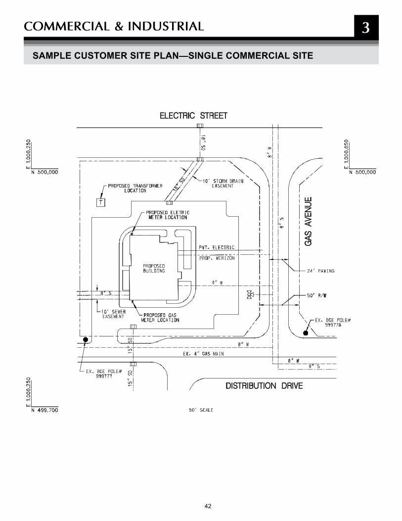
43 42 43
COmmERCIAL & INDUsTRIAL 3
SAMPLE CUSTOMER SITE PLAN—SINGLE COMMERCIAL SITE

43 43
NOTEs
44 45
4
CONDUITThis section does not cover all of the guidelines on the requirements for conduit and manhole construction. For a more comprehensive explanation, please refer to the new Conduit Construction Booklet. For your convenience, the booklet is available one line at: bge.com
45
CONDUIT 4
SPECIFICATIONS FOR CUSTOMER INSTALLATION OF CONDUITS
Note: Conduit from the meter termination point to the secondary side of the transformer is the standard method of installation for most three-phase commercial and industrial secondary services. The direct-buried method is still a method of installation where conduit installation would be impractical. When required by BGE, the customer is responsible for designing and building ducts and conduit systems.
Direct-Buried Electric Conduit
Primary and Secondary Electric Conduit
1. Secondary conduit will be 4" minimum inside dimension I.P.S.
2. Primary conduit size varies, contact BGE representative for actual sizes.
3. BGE shall specify the number, size and configuration of ducts.
4. All direct-buried ducts shall be UL schedule 40.
5. All bends shall be no less than 36" in radius. A total of two (2) 90 degree bends are allowed in the conduit line (i.e., conduit turn up at transformer pad is one (1) 90-degree bend). One (1) additional, wide-radius bend (minimum radius of five feet for this additional bend) will be allowed. If this still will not be sufficient for the conduit design/construction, contact your BGE representative. A hand hole, splice/pull box or manhole may be required.
6. The customer shall pull a mandrel (1/2" smaller in diameter than the conduit and 6" long) through each duct prior to BGE cable installation, followed by a pulling line (1800 lb minimum tensile strength mule line preferred) which shall remain in each duct.
7. Customers will connect all electric conduit with sealed/glue couplings and terminate their conduit with bell ends and plugs.
8. Electrical ducts should be sloped away from the customer's building whenever possible to reduce the potential for water intrusion into the building as a result of failed or missing duct seals.
9. Required depth of conduit from final grade to top of conduit/conduit bank: 30" for secondary, minimum 36" for primary, minimum 48" maximum
10. Backfill evenly around duct with clean dry earth and mechanically tamp in 12" lifts.
11. Lengths of secondary duct banks shall be minimized to limit pulling distances and electrical losses. Any secondary duct lengths over 100 feet shall be approved by BGE prior to construction.
12. The minimum longitudinal separation between foreign structures and conduit should be as follows:
– Telephone/cable television conduit–3" of concrete or 12" of earth
– Gas, water, sanitary and oil mains–12" of earth
13. Splice/pull boxes or manholes may be required by BGE depending on the specific installation.
14. If electric service is being supplied from a new transformer, the customer's duct shall enter the transformer as shown on page titled "Turning Conduit into Transformer Pads" in section two (2) of this booklet, page 50.
15. If electric service is being supplied from an existing transformer, the customer shall end the secondary duct 5' from the secondary side of the transformer at a location determined by BGE. BGE will continue the duct into the transformer based on field conditions.
4

46 47
CONDUIT 4
SPECIFICATIONS FOR CUSTOMER INSTALLATION OF CONDUITS (CONT'D)
Direct-Buried Gas Sleeves
1. PVC UL Schedule 40 conduit (solid wall, not split) may be used as a sleeve installed in advance of paving to facilitate future installation of small size (2" and smaller) gas services where casing is not required. The ends of the sleeve should not be sealed after insertion of the carrier pipe to avoid containment of gas in case of a gas leak. However, the end of the sleeve on a service line nearest the building should be sealed after installation of the carrier pipe and the opposite end of the sleeve left open.
2. Gas services common trenched with electric duct shall be in sleeves.
3. Gas sleeves shall not exceed one 45-degree bend, and must terminate a minimum of 5' from all buildings/structures. Note: 90-degree bends are not allowed.
4. Only one gas service per sleeve is permitted.
5. Gas sleeves will not be concrete encased.
6. Installation of gas piping into any electrical conduit bank is prohibited.
7. Installation of minimum 4" sleeve and underground warning tape unless otherwise specified for natural gas service under paving, or under improved areas as required by BGE or any city or county regulations. (Applicable only for plastic gas service sizes: 1/2" CTS; 3/4" IPS; 1" CTS; 1-1/4" CTS; 1-1/4" IPS and 2" IPS.)
8. Lengths of continuous runs for gas sleeves shall not exceed 300 feet.
9. Mechanical joints on gas services are not allowed inside of sleeves. Open trench space provision must be made to allow BGE room to make these connections.
10. Warning tape is required above all gas sleeves and can be purchased and delivered to your site from BGE's Contractor Supplier (See page 28).
11. PVC sleeves for gas shall be two (2) standard pipe sizes larger than the gas pipe.
12. Vertical separation for gas sleeves when crossing any foreign structure is a minimum of 12".
13. Radial separation between gas sleeves and electric cable or conduit is a minimum of 12".
47
CONDUIT 4
Concrete Encased Electric Conduit
1. Duct banks must be concrete encased if any ducts are stacked vertically (one on top of the other). All 2x2 duct banks and greater must be concrete encased.
2. If ducts are within municipality right-of-way, it may be required to concrete-encase. Check with local Department of Public Works for specific requirements.
3. BGE shall specify the number, size and configuration of ducts.
4. Schedule 20 PVC must be used for concrete encased ducts.
5. Bends shall be no less than 36” in radius. A total of two (2) 90-degree bends are allowed in the conduit line. If this still will not be sufficient for the conduit design/construction, contact your BGE representative. A manhole, splice/pull box or hand box may be required.
6. Duct spacers that maintain a 2” separation between ducts are required every 6 1/2 - 7'.
Required depth of conduit from final grade to top of conduit/conduit bank (unless otherwise approved by BGE): 30" for secondary, minimum. 36" for primary, minimum. 48" maximum.
7. Only standard 2,500-psi ready-mix concrete with 1/2" pea gravel will be approved for encasement.
8. After concrete cures for 24 hours, backfill around duct bank with clean select soil and mechanically tamp in 8” lifts.
9. The customer shall pull a mandrel (1/2" smaller in diameter than the conduit and 6" long) through each duct prior to BGE cable installation, followed by a pulling line (1800 lb mule line preferred), which shall remain in each duct.
10. Secondary customer switchgear installations that incorporate metering compartments that are supplied by eight or more ducts, require a pit to be installed under that compartment. The pit shall be 2' deep and measure 1" less than the width and depth of the compartment. Ducts must enter the pit from the bottom, not the sides. Refer to the BGE Gas & Electric Metering Manual under the New Construction Services section available at bge.com for more details.
11. If electric service is being supplied from a new transformer, the customer's duct shall enter the transformer as shown on page titled "Turning Conduit into Transformer Pads" in section two (2) of this booklet.
12. If electric service is being supplied from an existing transformer, the customer shall end the secondary duct five feet from the secondary side of the transformer at a location determined by BGE. BGE will continue the duct into the transformer based on field conditions.
SPECIFICATIONS FOR CUSTOMER INSTALLATION OF CONDUITS (CONT'D)
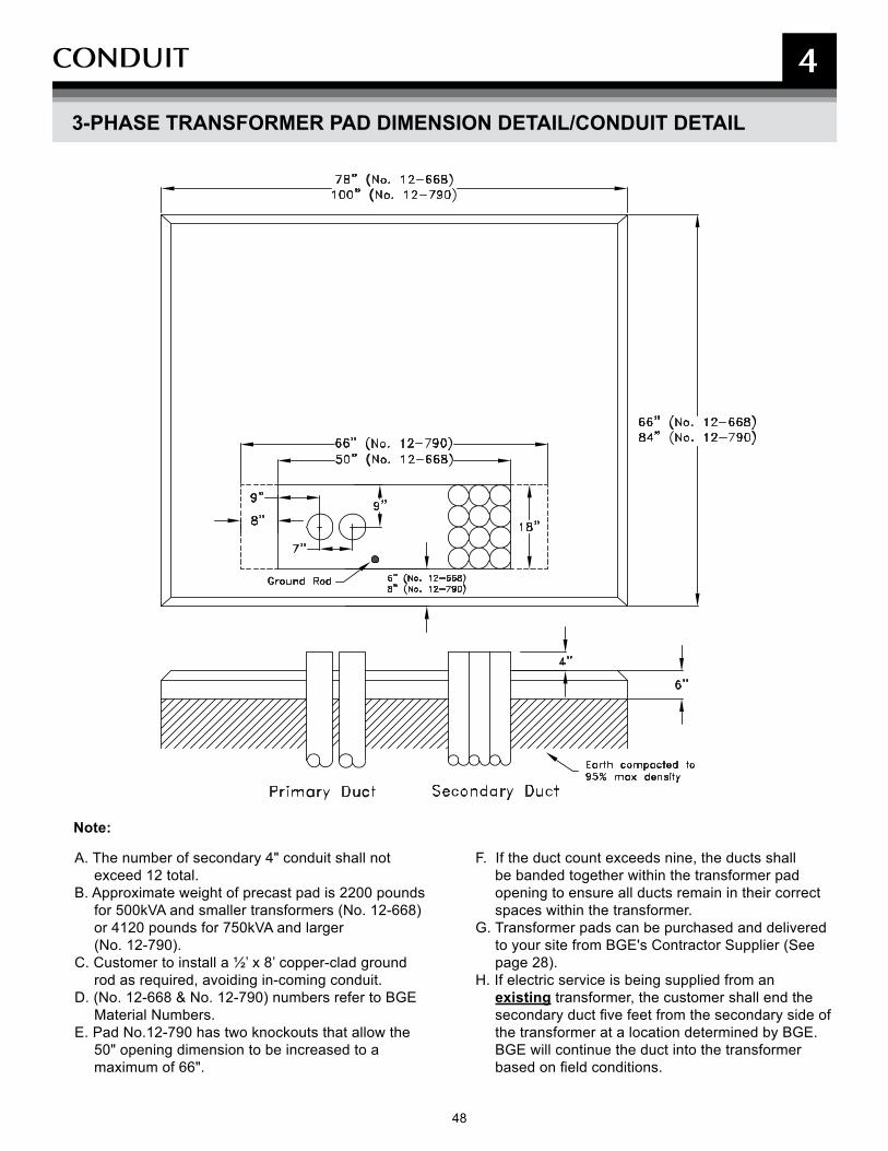
48 49
CONDUIT 4
3-PHASE TRANSFORMER PAD DIMENSION DETAIL/CONDUIT DETAIL
A. The number of secondary 4" conduit shall not exceed 12 total.
B. Approximate weight of precast pad is 2200 pounds for 500kVA and smaller transformers (No. 12-668) or 4120 pounds for 750kVA and larger (No. 12-790).
C. Customer to install a ½’ x 8’ copper-clad ground rod as required, avoiding in-coming conduit.
D. (No. 12-668 & No. 12-790) numbers refer to BGE Material Numbers.
E. Pad No.12-790 has two knockouts that allow the 50" opening dimension to be increased to a maximum of 66".
F. If the duct count exceeds nine, the ducts shall be banded together within the transformer pad opening to ensure all ducts remain in their correct spaces within the transformer.
G. Transformer pads can be purchased and delivered to your site from BGE's Contractor Supplier (See page 28).
H. If electric service is being supplied from an existing transformer, the customer shall end the secondary duct five feet from the secondary side of the transformer at a location determined by BGE. BGE will continue the duct into the transformer based on field conditions.
Note:
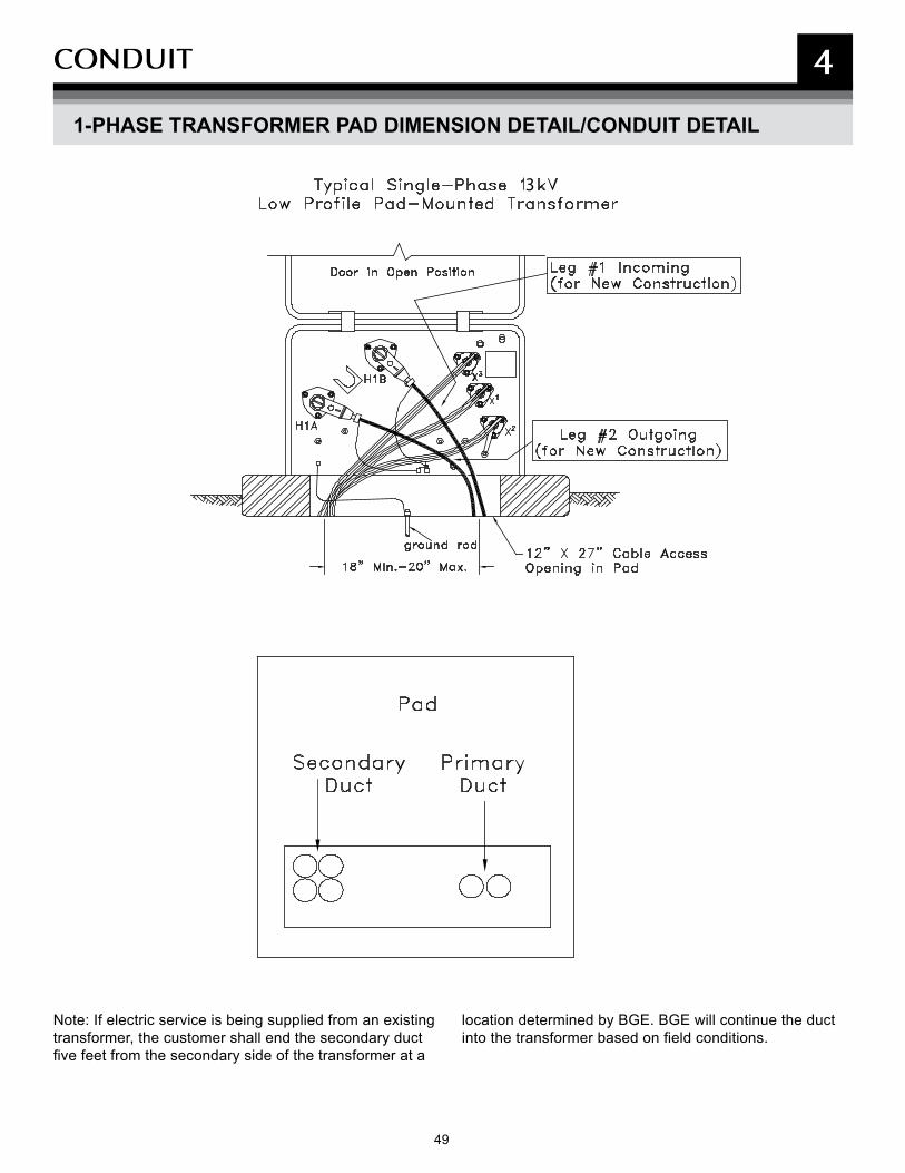
49
CONDUIT 4
1-PHASE TRANSFORMER PAD DIMENSION DETAIL/CONDUIT DETAIL
3
Note: If electric service is being supplied from an existing transformer, the customer shall end the secondary duct five feet from the secondary side of the transformer at a
location determined by BGE. BGE will continue the duct into the transformer based on field conditions.
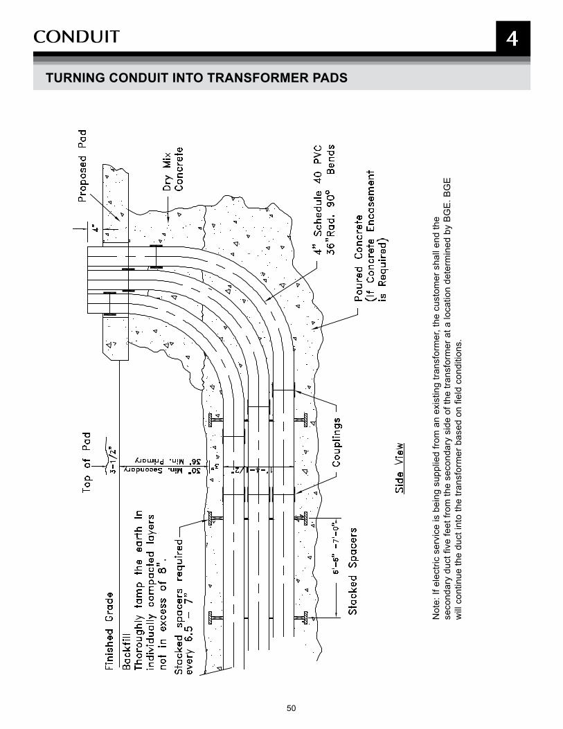
50 51
CONDUIT 4
TURNING CONDUIT INTO TRANSFORMER PADS
Not
e: If
ele
ctric
ser
vice
is b
eing
sup
plie
d fro
m a
n ex
istin
g tra
nsfo
rmer
, the
cus
tom
er s
hall
end
the
seco
ndar
y du
ct fi
ve fe
et fr
om th
e se
cond
ary
side
of t
he tr
ansf
orm
er a
t a lo
catio
n de
term
ined
by
BG
E. B
GE
w
ill c
ontin
ue th
e du
ct in
to th
e tra
nsfo
rmer
bas
ed o
n fie
ld c
ondi
tions
.

51
CONDUIT 4
STANDARD DUCT BANk ARRANGEMENT/INSTALLATION
4W X 2H
2W X 4H
Duct SpaceTypical
2W X 3H
2W X 2H
2W X 1H
3W X 3H
3W X 2H
3W X 1H
5" - 34"
4" - 30"
6"- 21"
4"- 17"
5"- 19"
3"
3"
26 1/
2"
29 1/
2"
23 1/
2"
3"2"
4"-
5"-
6"-
23 1/
2"
3"
4"-
2"
26 1/
2"
29 1/
2"6"
-
5"-
6"-
5"-
4"-
3"
3"
3"
21"
19"
17"
3"
5"- 19"
6"- 21"
4"- 17"
2"
5"-
3"2"
4"-
6"-
3"
5"- 19"
2"
4"- 17"
6"- 21"
3"
3" 3"2"
4"- 17"
6"- 21"
5"- 19"1/
2"
3"
10
1/2"
1/2"
1211
6"-
5"-
4"-
2" 17"
29 1/2"26 1/2"
23 1/2"
3"
4"-
2"
5"- 6"-
3"
3"
4"-
29 1/2"
26 1/2"
23 1/2"4"-
3" 2"
6"-
5"-
3"
3"3"
21"
19"
6"-
5"-
3" 2"
3" 2"
1/2"
29 1/2"
23 1/2"26 1/2"
4"-
3" 2"
6"-
5"-
3"
10
3"
1/2"
1/2"
11 12 6" - 38"
34"
5"-
3"
4"-
2"
30"
6"-
38"
3"
3"
3"
3"
3"
5"-
19"
4"-
17"
6"-
21"
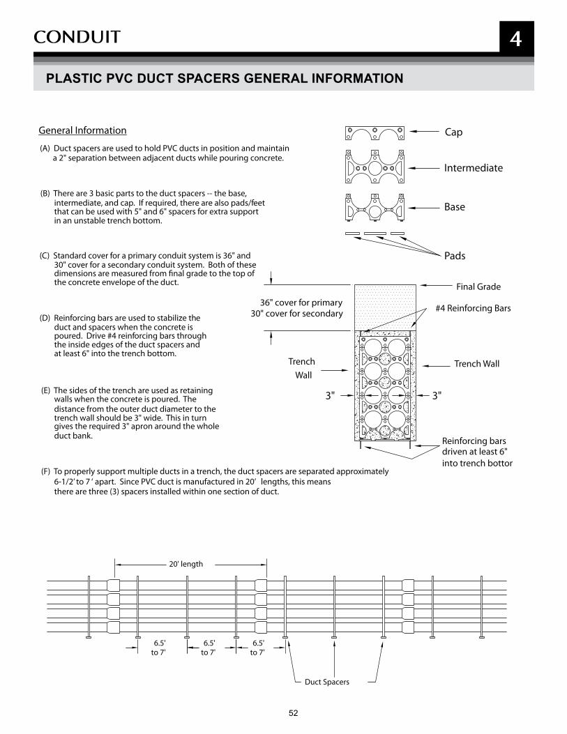
52 53
CONDUIT 4
PLASTIC PVC DUCT SPACERS GENERAL INFORMATION
Duct Spacers
(A) Duct spacers are used to hold PVC ducts in position and maintain a 2" separation between adjacent ducts while pouring concrete.
(B) There are 3 basic parts to the duct spacers -- the base, intermediate, and cap. If required, there are also pads/feetthat can be used with 5" and 6" spacers for extra supportin an unstable trench bottom.
6.5' to 7'
6.5' to 7'
6.5'to 7'
20' length
(F) To properly support multiple ducts in a trench, the duct spacers are separated approximately6-1/2’ to 7 ‘ apart. Since PVC duct is manufactured in 20’ lengths, this meansthere are three (3) spacers installed within one section of duct.
General Information
(D) Reinforcing bars are used to stabilize theduct and spacers when the concrete ispoured. Drive #4 reinforcing bars through the inside edges of the duct spacers and at least 6" into the trench bottom.
(E) The sides of the trench are used as retainingwalls when the concrete is poured. The distance from the outer duct diameter to the trench wall should be 3" wide. This in turn gives the required 3" apron around the wholeduct bank. Reinforcing bars
driven at least 6"
Final Grade
36" cover for primary30" cover for secondary
into trench bottom
Trench Wall
#4 Reinforcing Bars
3"3"
TrenchWall
(C) Standard cover for a primary conduit system is 36" and30" cover for a secondary conduit system. Both of thesedimensions are measured from �nal grade to the top ofthe concrete envelope of the duct.
Pads
Base
Intermediate
Cap

53
CONDUIT 4
ROAD CROSSING SPECIFICATIONS
Final Grade of Road Surface
24” Minimum
49.5” Minimum - 60” Maximum
Electronic Marker
Gas MainConsult BGE if gas main is larger than 2” plastic
Telephone &CATV Cables
PrimaryElectricCable(s)
SecondaryElectricCable(s)
Street Light Cable
Allowance for Rock Bottom
ElectronicMarker
ElectronicMarker
12” 12”
• A minimum 12” radial separation must be maintained between gas and any other utility.
• Allow a minimum 6” separation between primary ducts or between primary and secondary ducts.
• Place an electronic marker 12” above the end of the PVC duct crossing(s).
NOTES:
• All ducts to be 4” PVC SCH 40 unless otherwise noted. Ducts must extend a minimum 5’ beyond proposed paving.
• Place an electronic marker 12” above the end of each PVC duct crossing(s).
• Install a PVC duct plug on the end of each duct crossing(s).
NOTES:

55 54 55
NOTEs

55
5
REsIDENTIAL
55
NOTEs

57 56
REsIDENTIAL
56
The procedures and specifications in this section apply to residential projects which include the following:
• A single home
• A new home within a development (service lateral)
• A development consisting of 4 or fewer homes/lots
• Temporary service to a construction/sales trailer
• A development consisting of 5 or more homes/lots
5
57
REsIDENTIAL 5
CONDITION OF ELECTRIC SUPPLY
Customer electrical loads are to be balanced in such a way that the imbalance between any two phases or legs is less than 10 percent. (Reference BGE Service Tariff sections 9.121 and 9.132. Customer's equipment has been significantly damaged by severe load imbalances.)
Electric Service Supply Points• BGE will supply one service connection:
a. For all the requirements of a single property when the supply is for a group of buildings, the supply point is located, wherever practicable, at a location central to the group.
b. For any separate building of a group, provided such service is for the entire requirements of that building.
c. For any separate building occupied by one or more customers.
• Where practicable, a single loop will be provided for a pair of adjoining buildings.
• BGE will supply one meter installation for all requirements of each customer at each supply point:
a. Where two or more customers are supplied from one service connection, a centralized meter location is required wherever practicable.
b. Each meter installation must have a separate application of the rate schedule.
• BGE provides and considers as “one service connection” and as “one meter installation”:
a. The combination of single-phase and three-phase services.
b. Two or more service connections of the same characteristics where required for a single customer by reason of the size of the load (such as a lighting load in excess of the capacity of one phase distribution) or by reason of the character of the load (such as welders where a combination on the same service with lighting is impracticable).
Note: All electric facility installation, lines, and equipment, must conform to the latest edition of the BGE Gas & Electric Metering Manual available under the New Construction Services section on bge.com
Builder/Developer/Customer Responsibilities• Submit your completed Service Application as early as
possible in your planning process.
• Provide on premise, without charge, suitable space and supporting structure acceptable to BGE for metering and service equipment. BGE will approve compartments in switchgear to building metering instrument transformers, unmetered service equipment, or cable termination facilities.
• All service equipment other than that specifically stated is furnished, installed, and maintained by you (or the owner), including the service entrance, the service switch or circuit breaker (including the wiring to BGE’s metering equipment where the service switch or circuit breaker is located on the line side of the meter), and any protective equipment required on your distribution system. Where other than a self-contained meter is required, you provide the raceway between BGE’s instrument transformers and the meter.
• Where you elect to furnish and install prefabricated multi-meter socket assemblies, install approved devices. BGE will provide a list of approved devices. Connections will not be made to a device that has not been approved prior to its installation.
• Where applicable, furnish and install conduit, manholes and splice/pull boxes per BGE specifications.
• Where applicable, BGE will install approved meter protection at customer’s expense.
• Provide certificate of approval from local jurisdiction to verify conformance with these specifications. The job will not be released to construction until this is received.
• For townhouse developments, additional requirements may exist. See the Townhouse Meter Installation Guidelines in this booklet for details.
59 58
REsIDENTIAL 5
CONDITIONS OF ELECTRIC SUPPLY (CONT'D)
BGE Responsibilities• Contact the customer within 10 days of our receipt of
the completed service application.
• Conduct initial site visit for planning and designing job.
• Install electric service per extension/relocation contract or gas service sketch.
• Furnish and install the transformers required to step down to secondary distribution system voltage and regulators required on BGE’s distribution system. BGE also furnishes and maintains and, if practicable, installs its meter connection device.
• Furnish and install secondary cables in customer or Baltimore City DPW conduit.
• Terminate and energize all BGE cables.
• Furnish and install all meters after receipt of certificate of approval from the jurisdictional authority for both gas and electric.
• Install BGE’s transformers and appurtenant equipment for general distribution purposes, which normally are located on poles in streets, alleys, and lot lines or on ground level pads adjacent to lot lines, or in manholes or vaults in the street or sidewalk in cable and conduit areas. Where these facilities are necessary solely for your service requirements, they normally are located on your premises.
• Furnish and install single phase transformer pads.
Local Jurisdiction Responsibilities• Upon application by the licensed electrician, issue
the appropriate permit for the installation of customer wiring and equipment, if applicable.
• Inspect and approve customer’s wiring and equipment.
• Provide BGE with certificate of approval notification for customer’s wiring and equipment.
Electrical Service Entrance— Service at Secondary Distribution Systems Voltages• The service switch or circuit breaker must be installed
on the load side of the meter, except where the jurisdictional authority requires it to be installed on the line side. Where the installation is on the line side, the service switch or circuit breaker must be so designed that the unmetered wiring is inaccessible without breaking the seal, even during the renewal of switch fuses. Fusible disconnects of the pullout type are acceptable only where specifically approved by BGE.
• You must also provide on premise, without charge, space (including a vault, if required) satisfactory to BGE for the transformers and equipment necessary for your service. See Illustration Section in this booklet for details.
Transformer Vaults• If BGE requires a vault on premise, you must provide one.
Overhead Electrical Service Entrance Location• Service entrances must be located such that the
service drop wires and service head are out of reach from doors, windows, porches, and the like.
• Service entrances for adjoining houses must, where practicable, be arranged such that each service drop will supply two houses. Where such houses have an area way between them, the service entrance must be located on the rear wall.
• In the event it becomes necessary to change the service entrance wiring, the service entrance location must conform to these requirements.
Electrical Service Drop (or Loop) Attachment• Brackets for the attachment of the service drop (the
wire span to your building) are installed by BGE, unless notified otherwise, at a point meeting the drop clearance required by the inspection authority having jurisdiction. In addition, this point of attachment must
59
REsIDENTIAL 5
CONDITIONS OF ELECTRIC SUPPLY (CONT'D)
be readily accessible to BGE at all times and must be sufficient to withstand the maximum pull for the required service drop.
• Where porches, awnings, or other obstructions render the point of attachment to a building inaccessible by extension ladder for installation and maintenance, suitable provisions for attaching the drop at a location accessible by extension ladder (and usually at the outer edge of these obstructions) must be provided by you.
• On multiple-story buildings, the point of attachment must be above the second floor windows.
• Where additions or alterations to a building render the point of attachment inaccessible, you must, at your expense, relocate the service entrance wiring and provide suitable means for supporting the drop.
Support Structure for Electrical Service Drop• Mast on low building: Where the building is of
insufficient height to provide the required clearance for the service drop, it’s your responsibility to provide and bolt to the building a mast of the proper length, clearance, and strength.
• Free-standing pole or timber: Where there are circumstances that do not permit the connection of a drop directly to your building, or there is otherwise insufficient support, or there is no building to which the drop may be connected, you must provide and erect a suitable pole or structure. This suitable structure must be in accordance with BGE’s layout. It must be the proper length to provide the required clearance for the drop and of sufficient size for the load. The point of BGE’s service connection to the customer-owned pole or structure is the load-end of the pole.
Overhead Electrical Service Entrance Conductors• Between the point of attachment of the service drop
and the meter, the conductors must be installed:
a. As service entrance cable, b. In rigid metal conduit, or c. In electrical metallic tubing. Except that, on
multiple meter installations, the horizontal runs of unmetered wiring beneath the meters must be installed in sealable wire troughs.
• A suitable service head must be provided and the conductors must extend beyond the service head sufficiently to enable BGE to make connections to the service drop.
• Where, with indoor metering, the length of service entrance cable inside the building is more than 5 feet, you must enclose it in rigid or flexible metal conduit, electrical metallic tubing, or a sealable wire trough from the point of entry into the building to the point of attachment to the meter connection devices.
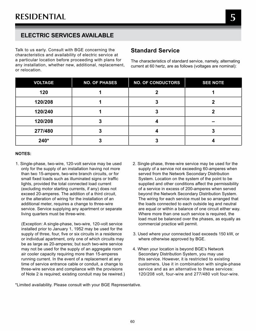
60 61
REsIDENTIAL 5
ELECTRIC SERVICES AVAILABLE
*Limited availability. Please consult with your BGE Representative.
Talk to us early. Consult with BGE concerning the characteristics and availability of electric service at a particular location before proceeding with plans for any installation, whether new, additional, replacement, or relocation.
Standard ServiceThe characteristics of standard service, namely, alternating current at 60 hertz, are as follows (voltages are nominal):
VOLTAGE NO. OF PHASES NO. OF CONDUCTORS SEE NOTE
120 1 2 1
120/208 1 3 2
120/240 1 3 2
120/208 3 4 –
277/480 3 4 3
240* 3 3 4
NOTES:
1. Single-phase, two-wire, 120-volt service may be used only for the supply of an installation having not more than two 15-ampere, two-wire branch circuits, or for small fixed loads such as illuminated signs or traffic lights, provided the total connected load current (excluding motor starting currents, if any) does not exceed 20-amperes. The addition of a third circuit, or the alteration of wiring for the installation of an additional meter, requires a change to three-wire service. Service supplying any apartment or separate living quarters must be three-wire.
(Exception: A single-phase, two-wire, 120-volt service installed prior to January 1, 1952 may be used for the supply of three, four, five or six circuits in a residence or individual apartment, only one of which circuits may be as large as 20-amperes; but such two-wire service may not be used for the supply of an aggregate room air cooler capacity requiring more than 15-amperes running current. In the event of a replacement at any time of service entrance cable or conduit, a change to three-wire service and compliance with the provisions of Note 2 is required; existing conduit may be rewired.)
2. Single-phase, three-wire service may be used for the supply of a service not exceeding 60-amperes when served from the Network Secondary Distribution System. Location on the system of the point to be supplied and other conditions affect the permissibility of a service in excess of 200-amperes when served beyond the Network Secondary Distribution System. The wiring for each service must be so arranged that the loads connected to each outside leg and neutral are equal or within a balance of one circuit either way. Where more than one such service is required, the load must be balanced over the phases, as equally as commercial practice will permit.
3. Used where your connected load exceeds 150 kW, or where otherwise approved by BGE.
4. When your location is beyond BGE’s Network Secondary Distribution System, you may use this service. However, it is restricted to existing customers. Use it in combination with single-phase service and as an alternative to these services: 120/208 volt, four-wire and 277/480 volt four-wire.
61
REsIDENTIAL 5
INCREASE IN LOAD TO EXISTING CUSTOMERS (HEAVY-UP)
• As the customer’s electric load increases, BGE will make appropriate alterations, if necessary, to its distribution system to provide for the increase.
• For a residential customer, BGE provides whatever distribution equipment may be necessary to accommodate the increase in load at its expense, except that the cost of breaking and replacing paving, hole hogging, directional boring and installing ducts, is fully chargeable to the customer.
• You are responsible for indicating where all private infrastructures are located (sprinkler systems, electric dog fences, low-voltage garden lighting, etc.), and where we can dig test holes, and for clearing anything in the path of BGE’s construction.

62 63
REsIDENTIAL 5
CONDITIONS OF GAS SUPPLY
All gas installation, lines, and equipment must conform to the latest edition of the BGE Gas & Electric Metering Manual under the New Construction Service section available at bge.com
Builder/Developer/Customer Responsibilities• Complete Service Application including gas appliance
load information and required delivery pressure, such as Standard, 2 PSIG, or other as specified.
• Suitably mark location of gas service and meter assembly location per BGE specifications and approval. BGE will install gas service and a meter assembly at the front of the building or the side wall, up to a maximum of 5’ back from the front wall.
• Provide BGE with a reasonable service date.• Notify BGE when the site is within six inches of final
grade.• Provide a certificate of approval from local jurisdiction to
verify conformance with their specifications. The job will not be released to construction until this is received.
• Where applicable, BGE will install approved meter protection at customer’s expense.
• For townhouse developments, additional requirements may exist.
BGE Responsibilities • Contact customer within 10 days of our receipt of the
completed service application.• Conduct a pre-site inspection, if necessary.• Install gas service per extension/relocation contract or
gas service sketch.• Confirm delivery pressure (Standard or 2 PSIG) from
the certificate of approval, if available.• Install service and gas meter bar assembly with a
customer’s main gas valve.• Provide gas service to the customer by following either
two options:
If the meter certificate has NOT been received, BGE will:• Base the delivery pressure (Standard or 2 PSIG) on the
customer service agreement/contract;• Complete the necessary tests and leak checks on the
service;• Leave the service valve in the “off” position (operated by
BGE only);• Set the meter bar assembly and install a meter nut plug
at the meter inlet connection and perform a leak test;• Leave the customer’s main gas valve in the “off” position
and plug its outlet;
• Complete the new gas service tag which notifies the customer to call the licensed plumber to have the fuel line inspected. Note that the gas meter will not be set.
If the meter certificate has been received, BGE will:• Base the delivery pressure (Standard or 2 PSIG) on the
customer service agreement/contract;• Complete the necessary tests and leak checks on
the service;• Leave the service valve in the “on” position (operated
by BGE only);• Set the meter bar assembly including the meter and
leak test;• Leave the customer’s main gas valve in the “off” position
and plug its outlet;• Complete the new gas service tag which notifies the
customer to call the licensed plumber to introduce gas into the fuel line.
Licensed Plumber Responsibilities
• Obtain all permits for customer’s gas piping and equipment.
• Install, inspect, and test new customer piping and equipment in accordance with the National Fuel Gas Code and/or any requirements of the local jurisdiction having authority.
• Obtain all certificates of approval from local jurisdiction for customer’s gas piping and equipment, then contact BGE to verify receipt of the certificates.
• Upon the completion of the meter assembly, remove plug at the outlet of the customer’s main gas valve and connect the customer’s fuel line.
• For multi-meter manifold installations, label customer fuel lines.
• Open the customer’s main gas valve and introduce gas into the fuel line.
• Test for leakage of the piping, equipment, connections, and valves using gas supplied at its supply pressure per the National Fuel Gas Code and/or any requirements of the local jurisdiction having authority.
• Place all gas equipment in operation in accordance with manufacturers’ instructions and specifications, and the National Fuel Gas Code and/or any requirements of the local jurisdiction having authority.
Local Jurisdiction Responsibilities• Inspect and approve the customer’s gas piping and
equipment.• Provide BGE with certificate of approval notification from
local jurisdiction for customer’s fuel lines.
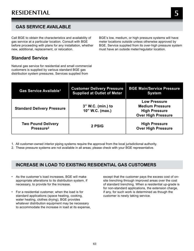
63
REsIDENTIAL 5
GAS SERVICE AVAILABLE
Call BGE to obtain the characteristics and availability of gas service at a particular location. Consult with BGE before proceeding with plans for any installation, whether new, additional, replacement, or relocation.
Standard Service Natural gas service for residential and small commercial customers is supplied by various standard BGE gas distribution system pressures. Services supplied from
BGE’s low, medium, or high pressure systems will have meter locations outside unless otherwise approved by BGE. Service supplied from its over-high pressure system must have an outside meter/regulator location.
Gas Service Available1 Customer Delivery Pressure Supplied at Outlet of Meter
BGE Main/Service Pressure System
Standard Delivery Pressure 3” W.C. (min.) to 10” W.C. (max.)
Low Pressure Medium Pressure
High Pressure Over High Pressure
Two Pound Delivery Pressure2 2 PSIG High Pressure
Over High Pressure
1. All customer-owned interior piping systems require the approval from the local jurisdictional authority.2. These pressure systems are not available in all areas; please check with your BGE representative.
INCREASE IN LOAD TO EXISTING RESIDENTIAL GAS CUSTOMERS
• As the customer’s load increases, BGE will make appropriate alterations to its distribution system, if necessary, to provide for the increase.
• For a residential customer, when the load is for standard applications (space heating, cooking, water heating, clothes drying), BGE provides whatever distribution equipment may be necessary to accommodate the increase in load at its expense,
except that the customer pays the excess cost of on-site trenching through improved areas over the cost of standard trenching. When a residential up-grade is for non-standard applications, the extension charge, if any, for such work is determined as though the customer is newly taking service.
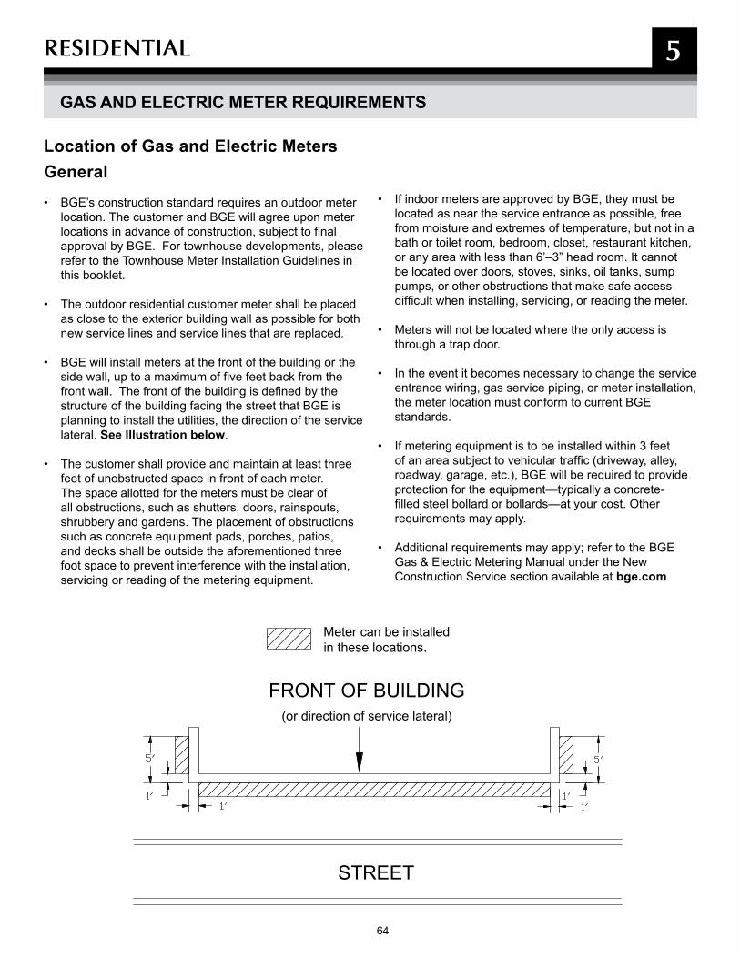
64 65
REsIDENTIAL 5
GAS AND ELECTRIC METER REQUIREMENTS
General• BGE’s construction standard requires an outdoor meter
location. The customer and BGE will agree upon meter locations in advance of construction, subject to final approval by BGE. For townhouse developments, please refer to the Townhouse Meter Installation Guidelines in this booklet.
• The outdoor residential customer meter shall be placed as close to the exterior building wall as possible for both new service lines and service lines that are replaced.
• BGE will install meters at the front of the building or the side wall, up to a maximum of five feet back from the front wall. The front of the building is defined by the structure of the building facing the street that BGE is planning to install the utilities, the direction of the service lateral. See Illustration below.
• The customer shall provide and maintain at least three feet of unobstructed space in front of each meter.The space allotted for the meters must be clear of all obstructions, such as shutters, doors, rainspouts, shrubbery and gardens. The placement of obstructions such as concrete equipment pads, porches, patios, and decks shall be outside the aforementioned three foot space to prevent interference with the installation, servicing or reading of the metering equipment.
• If indoor meters are approved by BGE, they must be located as near the service entrance as possible, free
from moisture and extremes of temperature, but not in a bath or toilet room, bedroom, closet, restaurant kitchen, or any area with less than 6’–3” head room. It cannot be located over doors, stoves, sinks, oil tanks, sump pumps, or other obstructions that make safe access difficult when installing, servicing, or reading the meter.
• Meters will not be located where the only access is through a trap door.
• In the event it becomes necessary to change the service entrance wiring, gas service piping, or meter installation, the meter location must conform to current BGE standards.
• If metering equipment is to be installed within 3 feet of an area subject to vehicular traffic (driveway, alley, roadway, garage, etc.), BGE will be required to provide protection for the equipment—typically a concrete-filled steel bollard or bollards—at your cost. Other requirements may apply.
• Additional requirements may apply; refer to the BGE Gas & Electric Metering Manual under the New Construction Service section available at bge.com
Location of Gas and Electric Meters
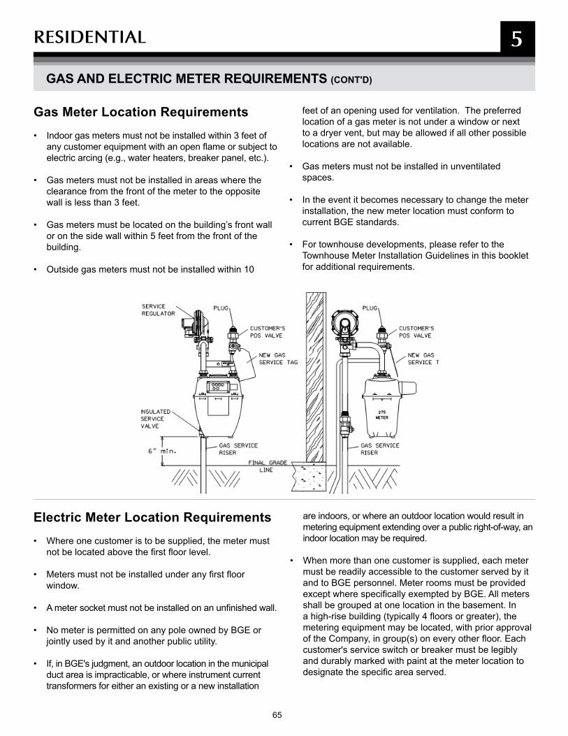
65
REsIDENTIAL 5
GAS AND ELECTRIC METER REQUIREMENTS (CONT'D)
Gas Meter Location Requirements• Indoor gas meters must not be installed within 3 feet of
any customer equipment with an open flame or subject to electric arcing (e.g., water heaters, breaker panel, etc.).
• Gas meters must not be installed in areas where the clearance from the front of the meter to the opposite wall is less than 3 feet.
• Gas meters must be located on the building’s front wall or on the side wall within 5 feet from the front of the building.
• Outside gas meters must not be installed within 10
feet of an opening used for ventilation. The preferred location of a gas meter is not under a window or next to a dryer vent, but may be allowed if all other possible locations are not available.
• Gas meters must not be installed in unventilated spaces.
• In the event it becomes necessary to change the meter installation, the new meter location must conform to current BGE standards.
• For townhouse developments, please refer to the Townhouse Meter Installation Guidelines in this booklet for additional requirements.
Electric Meter Location Requirements• Where one customer is to be supplied, the meter must
not be located above the first floor level.
• Meters must not be installed under any first floor window.
• A meter socket must not be installed on an unfinished wall.
• No meter is permitted on any pole owned by BGE or jointly used by it and another public utility.
• If, in BGE's judgment, an outdoor location in the municipal duct area is impracticable, or where instrument current transformers for either an existing or a new installation
are indoors, or where an outdoor location would result in metering equipment extending over a public right-of-way, an indoor location may be required.
• When more than one customer is supplied, each meter must be readily accessible to the customer served by it and to BGE personnel. Meter rooms must be provided except where specifically exempted by BGE. All meters shall be grouped at one location in the basement. In a high-rise building (typically 4 floors or greater), the metering equipment may be located, with prior approval of the Company, in group(s) on every other floor. Each customer's service switch or breaker must be legibly and durably marked with paint at the meter location to designate the specific area served.
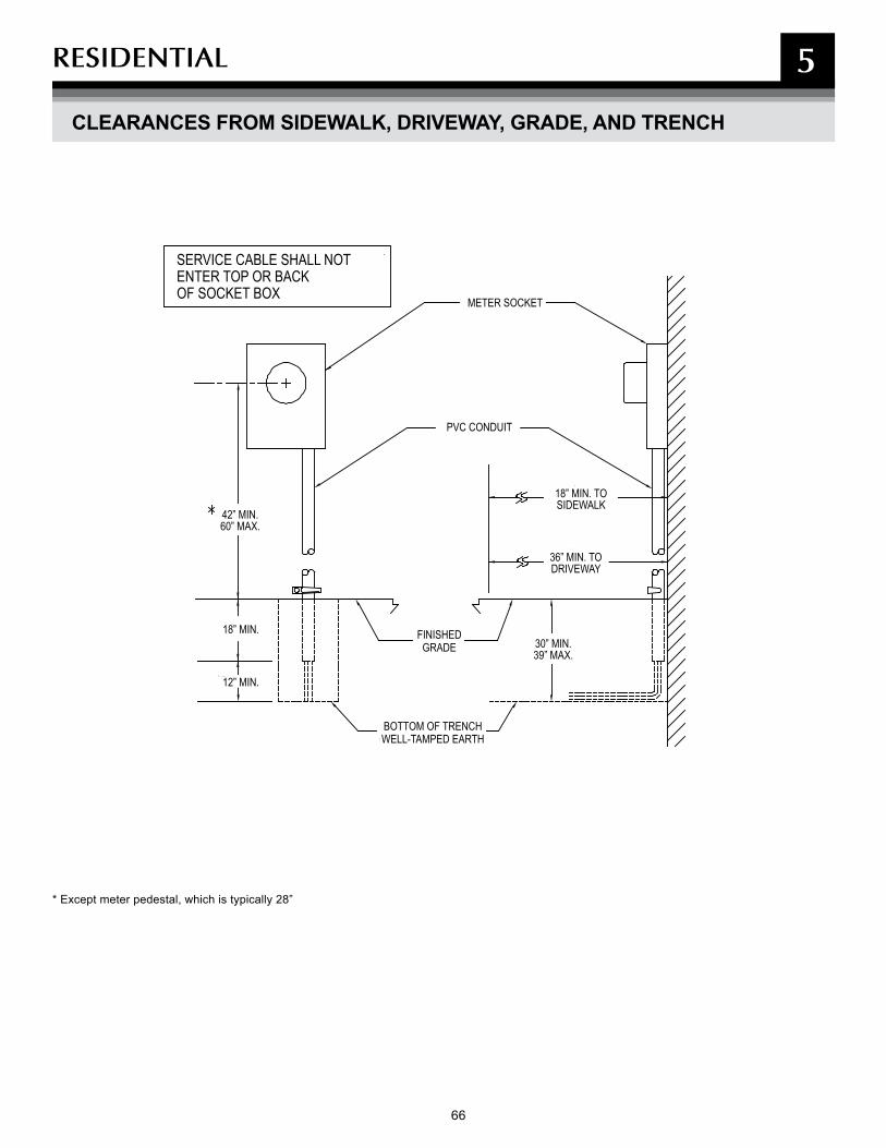
66 67
REsIDENTIAL 5
CLEARANCES FROM SIDEWALK, DRIVEWAY, GRADE, AND TRENCH
SERVICE CABLE SHALL NOTENTER TOP OR BACKOF SOCKET BOX
METER SOCKET
PVC CONDUIT
FINISHEDGRADE
BOTTOM OF TRENCHWELL-TAMPED EARTH
18” MIN. TO SIDEWALK
36” MIN. TO DRIVEWAY
30” MIN.39” MAX.
42” MIN.60” MAX.
18” MIN.
12” MIN.
* Except meter pedestal, which is typically 28”
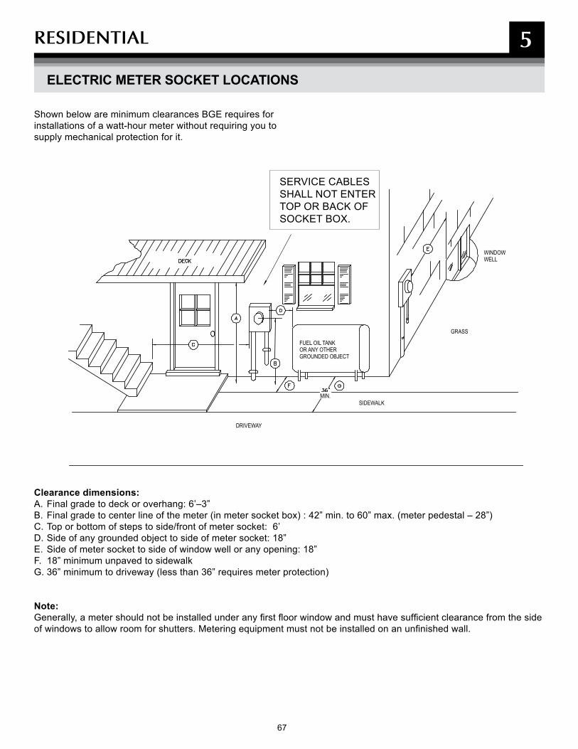
67
REsIDENTIAL 5
ELECTRIC METER SOCKET LOCATIONS
Clearance dimensions:A. Final grade to deck or overhang: 6’–3”B. Final grade to center line of the meter (in meter socket box) : 42” min. to 60” max. (meter pedestal – 28”)C. Top or bottom of steps to side/front of meter socket: 6’D. Side of any grounded object to side of meter socket: 18”E. Side of meter socket to side of window well or any opening: 18”F. 18” minimum unpaved to sidewalkG. 36” minimum to driveway (less than 36” requires meter protection)
Note: Generally, a meter should not be installed under any first floor window and must have sufficient clearance from the side of windows to allow room for shutters. Metering equipment must not be installed on an unfinished wall.
Shown below are minimum clearances BGE requires for installations of a watt-hour meter without requiring you to supply mechanical protection for it.
FUEL OIL TANKOR ANY OTHERGROUNDED OBJECT
SIDEWALK
GRASS
WINDOWWELL
DRIVEWAY
MIN.
SERVICE CABLES SHALL NOT ENTER TOP OR BACK OF SOCKET BOX.
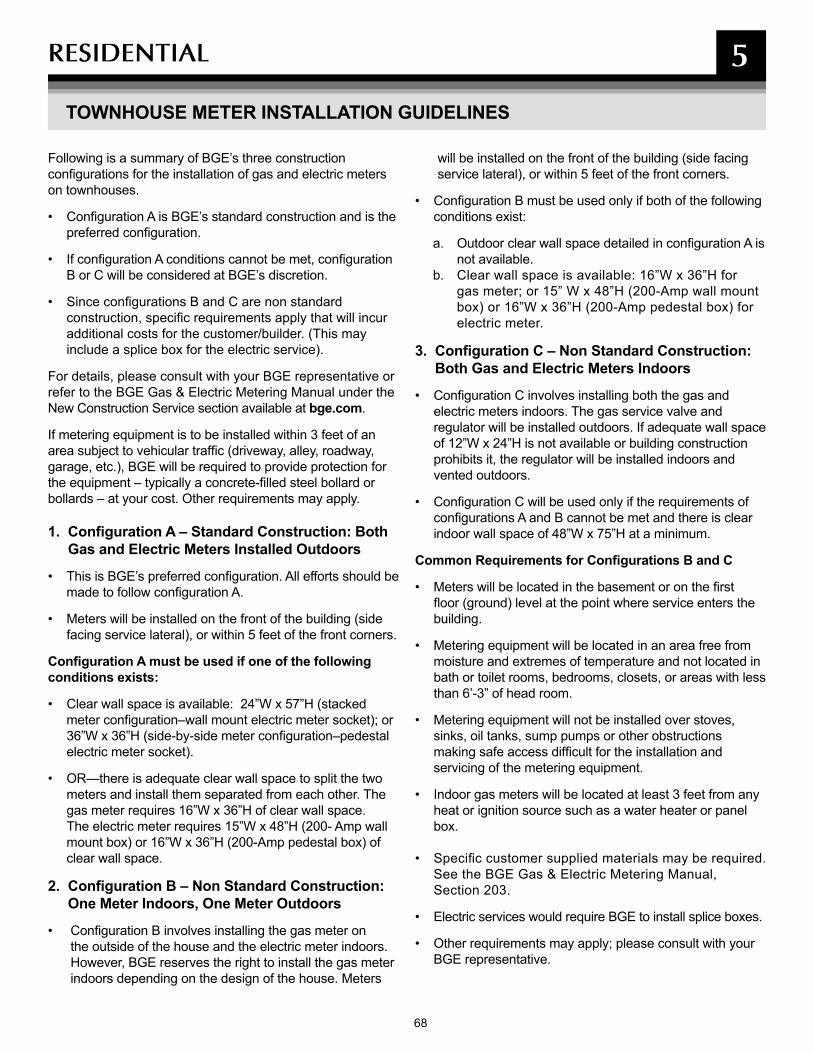
68 69
REsIDENTIAL 5
TOWNHOUSE METER INSTALLATION GUIDELINES
Following is a summary of BGE’s three construction configurations for the installation of gas and electric meters on townhouses.
• Configuration A is BGE’s standard construction and is the preferred configuration.
• If configuration A conditions cannot be met, configuration B or C will be considered at BGE’s discretion.
• Since configurations B and C are non standard construction, specific requirements apply that will incur additional costs for the customer/builder. (This may include a splice box for the electric service).
For details, please consult with your BGE representative or refer to the BGE Gas & Electric Metering Manual under the New Construction Service section available at bge.com.
If metering equipment is to be installed within 3 feet of an area subject to vehicular traffic (driveway, alley, roadway, garage, etc.), BGE will be required to provide protection for the equipment – typically a concrete-filled steel bollard or bollards – at your cost. Other requirements may apply.
1. Configuration A – Standard Construction: Both Gas and Electric Meters Installed Outdoors
• This is BGE’s preferred configuration. All efforts should be made to follow configuration A.
• Meters will be installed on the front of the building (side facing service lateral), or within 5 feet of the front corners.
Configuration A must be used if one of the following conditions exists:
• Clear wall space is available: 24”W x 57”H (stacked meter configuration–wall mount electric meter socket); or 36”W x 36”H (side-by-side meter configuration–pedestal electric meter socket).
• OR—there is adequate clear wall space to split the two meters and install them separated from each other. The gas meter requires 16”W x 36”H of clear wall space. The electric meter requires 15”W x 48”H (200- Amp wall mount box) or 16”W x 36”H (200-Amp pedestal box) of clear wall space.
2. Configuration B – Non Standard Construction: One Meter Indoors, One Meter Outdoors
• Configuration B involves installing the gas meter on the outside of the house and the electric meter indoors. However, BGE reserves the right to install the gas meter indoors depending on the design of the house. Meters
will be installed on the front of the building (side facing service lateral), or within 5 feet of the front corners.
• Configuration B must be used only if both of the following conditions exist:
a. Outdoor clear wall space detailed in configuration A is not available.
b. Clear wall space is available: 16”W x 36”H for gas meter; or 15” W x 48”H (200-Amp wall mount box) or 16”W x 36”H (200-Amp pedestal box) for electric meter.
3. Configuration C – Non Standard Construction: Both Gas and Electric Meters Indoors
• Configuration C involves installing both the gas and electric meters indoors. The gas service valve and regulator will be installed outdoors. If adequate wall space of 12”W x 24”H is not available or building construction prohibits it, the regulator will be installed indoors and vented outdoors.
• Configuration C will be used only if the requirements of configurations A and B cannot be met and there is clear indoor wall space of 48”W x 75”H at a minimum.
Common Requirements for Configurations B and C
• Meters will be located in the basement or on the first floor (ground) level at the point where service enters the building.
• Metering equipment will be located in an area free from moisture and extremes of temperature and not located in bath or toilet rooms, bedrooms, closets, or areas with less than 6’-3” of head room.
• Metering equipment will not be installed over stoves, sinks, oil tanks, sump pumps or other obstructions making safe access difficult for the installation and servicing of the metering equipment.
• Indoor gas meters will be located at least 3 feet from any heat or ignition source such as a water heater or panel box.
• Specific customer supplied materials may be required. See the BGE Gas & Electric Metering Manual, Section 203.
• Electric services would require BGE to install splice boxes.
• Other requirements may apply; please consult with your BGE representative.
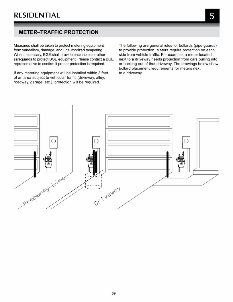
69
REsIDENTIAL 5
METER–TRAFFIC PROTECTION
Measures shall be taken to protect metering equipment from vandalism, damage, and unauthorized tampering. When necessary, BGE shall provide enclosures or other safeguards to protect BGE equipment. Please contact a BGE representative to confirm if proper protection is required.
If any metering equipment will be installed within 3 feet of an area subject to vehicular traffic (driveway, alley, roadway, garage, etc.), protection will be required.
The following are general rules for bollards (pipe guards) to provide protection. Meters require protection on each side from vehicle traffic. For example, a meter located next to a driveway needs protection from cars pulling into or backing out of that driveway. The drawings below show bollard placement requirements for meters next to a driveway.
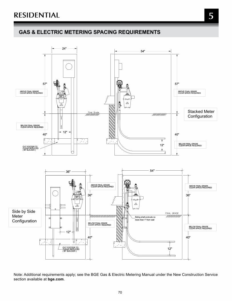
70 71
REsIDENTIAL 5
GAS & ELECTRIC METERING SPACING REQUIREMENTS
Note: Additional requirements apply; see the BGE Gas & Electric Metering Manual under the New Construction Service section available at bge.com.
Stacked Meter Configuration
Side by SideMeter Configuration
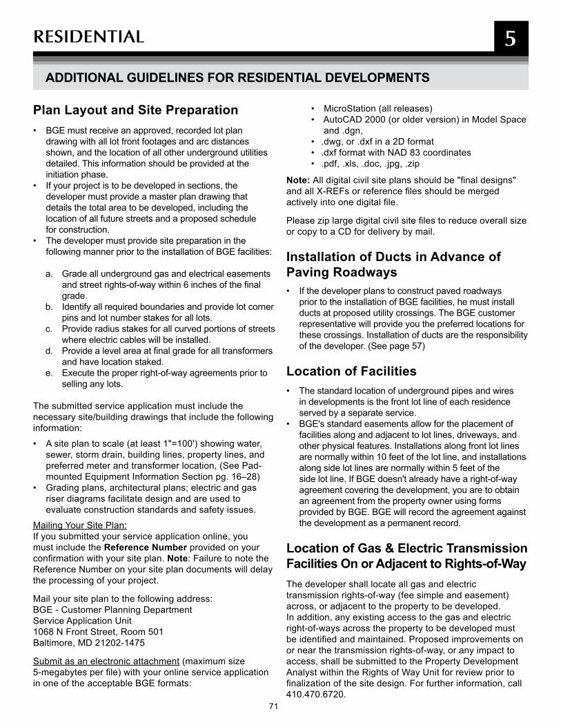
71
REsIDENTIAL 5
ADDITIONAL GUIDELINES FOR RESIDENTIAL DEVELOPMENTS
Plan Layout and Site Preparation• BGE must receive an approved, recorded lot plan
drawing with all lot front footages and arc distances shown, and the location of all other underground utilities detailed. This information should be provided at the initiation phase.
• If your project is to be developed in sections, the developer must provide a master plan drawing that details the total area to be developed, including the location of all future streets and a proposed schedule for construction.
• The developer must provide site preparation in the following manner prior to the installation of BGE facilities:
a. Grade all underground gas and electrical easements and street rights-of-way within 6 inches of the final grade.
b. Identify all required boundaries and provide lot corner pins and lot number stakes for all lots.
c. Provide radius stakes for all curved portions of streets where electric cables will be installed.
d. Provide a level area at final grade for all transformers and have location staked.
e. Execute the proper right-of-way agreements prior to selling any lots.
The submitted service application must include the necessary site/building drawings that include the following information:
• A site plan to scale (at least 1"=100') showing water, sewer, storm drain, building lines, property lines, and preferred meter and transformer location, (See Pad-mounted Equipment Information Section pg. 16–28)
• Grading plans, architectural plans; electric and gas riser diagrams facilitate design and are used to evaluate construction standards and safety issues.
Mailing Your Site Plan:If you submitted your service application online, you must include the Reference Number provided on your confirmation with your site plan. Note: Failure to note the Reference Number on your site plan documents will delay the processing of your project.
Mail your site plan to the following address:BGE - Customer Planning DepartmentService Application Unit1068 N Front Street, Room 501Baltimore, MD 21202-1475
Submit as an electronic attachment (maximum size 5-megabytes per file) with your online service application in one of the acceptable BGE formats:
• MicroStation (all releases)• AutoCAD 2000 (or older version) in Model Space
and .dgn,• .dwg, or .dxf in a 2D format• .dxf format with NAD 83 coordinates• .pdf, .xls, .doc, .jpg, .zip
Note: All digital civil site plans should be "final designs" and all X-REFs or reference files should be merged actively into one digital file.
Please zip large digital civil site files to reduce overall size or copy to a CD for delivery by mail.
Installation of Ducts in Advance of Paving Roadways• If the developer plans to construct paved roadways
prior to the installation of BGE facilities, he must install ducts at proposed utility crossings. The BGE customer representative will provide you the preferred locations for these crossings. Installation of ducts are the responsibility of the developer. (See page 57)
Location of Facilities• The standard location of underground pipes and wires
in developments is the front lot line of each residence served by a separate service.
• BGE's standard easements allow for the placement of facilities along and adjacent to lot lines, driveways, and other physical features. Installations along front lot lines are normally within 10 feet of the lot line, and installations along side lot lines are normally within 5 feet of the side lot line. If BGE doesn't already have a right-of-way agreement covering the development, you are to obtain an agreement from the property owner using forms provided by BGE. BGE will record the agreement against the development as a permanent record.
Location of Gas & Electric Transmission Facilities On or Adjacent to Rights-of-WayThe developer shall locate all gas and electric transmission rights-of-way (fee simple and easement) across, or adjacent to the property to be developed. In addition, any existing access to the gas and electricright-of-ways across the property to be developed must be identified and maintained. Proposed improvements on or near the transmission rights-of-way, or any impact to access, shall be submitted to the Property Development Analyst within the Rights of Way Unit for review prior tofinalization of the site design. For further information, call410.470.6720.
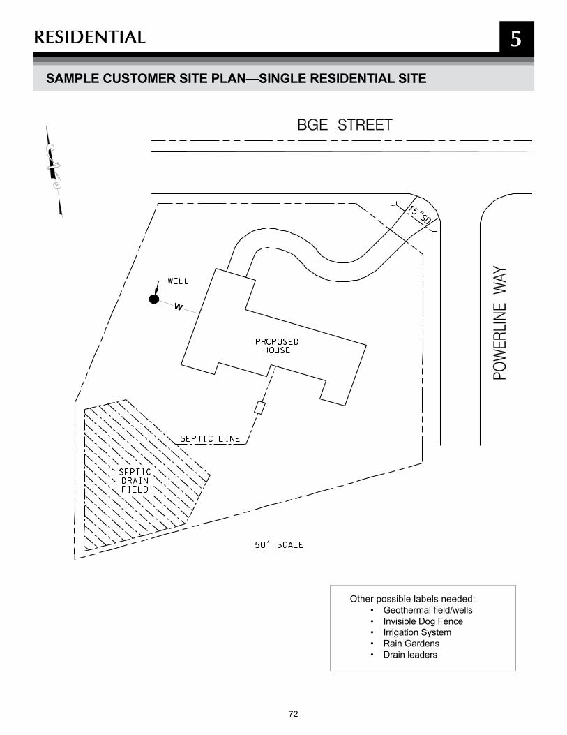
72 73
REsIDENTIAL 5
SAMPLE CUSTOMER SITE PLAN—SINGLE RESIDENTIAL SITE
Other possible labels needed:• Geothermal field/wells• Invisible Dog Fence• Irrigation System• Rain Gardens• Drain leaders
w

73
REsIDENTIAL 5
SAMPLE CUSTOMER SITE PLAN—DEVELOPMENT

75
NOTEs
74 75
75
6
DEFINITIONs & FREqUENTLy AskED qUEsTIONs
NOTEs
75

76 77
Following are definitions for various terms used in this manual and their source or sources where appropriate. Where no reference is provided, the definition given is that which is applicable to BGE’s practices.
Approach Main – Extensions of mains necessary to reach the boundary of a residential subdivision, industrial park, shopping center, a commercial or industrial property on which multiple buildings are to be located, or a single residential or commercial building lot.
BGE – Baltimore Gas and Electric Company or an employee properly qualified to represent Baltimore Gas & Electric Company.
Bollard – A concrete filled steel pipe, set in a concrete footer, to protect BGE equipment from vehicular damage.
BTU – British Thermal Unit
C & I – Commercial & Industrial
Certificate of Approval – Confirmation from municipalities/counties indicating approval that the electrical wiring/gas plumbing has passed inspection. After receiving this approval, BGE may install the meter.
CFH – Cubic Feet per Hour
CIAC (Contribution in Aid of Construction) – A non-refundable charge for electric service, determined by BGE, to serve the requested load.
Concrete Enclosed Duct Bank – Structure consisting of duct(s) spaced at pre-determined distance from each other and enclosed in concrete.
Conduit – A structure containing one or more ducts.
Conduit System – Any combination of duct, conduit, conduits, manholes, handholes, and vaults joined to form an integrated whole.
Connected Load – The amount of electrical power used by any electrical unit or appliance.
Customer – Any present or prospective user of BGE’s gas or electric service, or any person or entity representing him, such as the architect, engineer, electrical contractor, land developer, builder, etc.
Customer Main Gas Valve – Valve, owned by customer,
installed at the outlet of the meter set. For applications where a bypass is not installed, this valve serves as the connection point between utility piping and customer piping—that is “Point of Service.” See also Point of Service.
Delivery Pressure – The gas pressure which BGE provides to the customer and upon which the customer’s piping and equipment must be sized.
Delivery Pressure (Standard) – For design purposes it has been established as 3” w.c. to 10” w.c. at the outlet of the meter (at the customer’s main gas valve).
Delivery Pressure (2 PSIG) – For design purposes, it has been established as 2 pounds per square inch gauge with a plus / minus of 1% at the outlet of the meter (at the customer’s main gas valve).
Developer – Party responsible for constructing and providing improvements in a development, e.g., streets, sidewalks, and utility-ready lots.
Development – Planned project which is developed byDeveloper/Applicant in a recorded plot plan of one or more lots for construction of single-family residences, detached or otherwise, mobile homes, or apartment houses, all of which are intended for year-round occupancy.
Distribution Line – Electric supply line from which energy is delivered to transformers. Pipeline that delivers gas to a customer service line.
Distribution System – The mains, services, regulating and metering equipment, and appurtenances used to distribute gas or electricity from the source of supply to customers.
Doubtful Permanency (Service) – A service intended for two (2) years or less, such as for construction, exhibit, or carnival purposes. The temporary facility will be removed at the completion of its use.
Dry mix concrete – One part concrete to two parts gravel that when mixed with 4 parts water will provide a "Concrete 1-2-4 mix."
Duct – A single enclosed raceway for conductors or cable.
Excess Flow Valve (EFV) – A valve designed to potentially restrict the flow of natural gas through your underground service line if the pipe becomes separated. It is not designed to activate if you encounter any problems
DEFINITIONs AND FREqUENTLy AskED qUEsTIONs 6
DEFINITIONS

77
with internal piping or appliances on the inside of your house.
Ground – A conducting connection between an electrical circuit or piece of equipment and the earth, or to a conducting body that serves in place of the earth.
High Pressure (HP) – Refers to that part of BGE’s gas distribution system where the maximum operating pressure is established as 99 psig and the minimum operating pressure is 25 psig.
Improved Areas – Areas that have landscaping, lawns, or paved surfaces.
Load Information Sheet – A page within the BGE Service Application on which the customer lists, in detail, their gas and/or electric load requirements. The loads are used to determine the proper size of the BGE pipes, wires, and meters which need to be installed to provide adequate service to the customer.
Low Pressure (LP) – That part of BGE’s gasdistribution system where the maximum operating pressure is established as 10 inches water column and the minimum operating pressure is 3 inches water column.
Main – That part of a line which is located: (a) along a street or road which is a public highway used as a thoroughfare by the general public, and (b) along a private road or across private property and used for the supply in common of at least two separately metered buildings.
Medium Pressure (MP) – That part of BGE’s gas distribution system where the maximum operating pressure is 10 psig and the minimum operating pressure is 2 psig.
Meter – If used without other qualification, any device that is used by a utility to measure a quantity of gas or electricity.
Meter Assembly, Gas – That part of the BGE’s gas distribution system from the end of the service line to the Point of Service comprising all pipe, valves, fittings, meters, regulators, and appurtenances required.
Meter Socket – A device that provides support and means of electrical connection to a watt-hour meter. It has a wiring chamber, with provisions for conduit entrances and exits, and a means of sealing the meter in place. The word “socket” in this manual refers to meter socket.
Multiple Occupancy Building – A unified structure
containing five or more individual dwelling units.
Network Secondary Distribution Service – A type ofelectric service generally available only in certain parts of downtown Baltimore from a grid of interconnected secondary conductors.
Over High Pressure (OHP) – The part of BGE’s gas distribution system where the maximum operating pressure is typically established as 300 psig, but may be lower dependent upon specific line’s design, and the minimum operating pressure is 125 psig.
Point of Connection – In general, that point where facilities installed by BGE are connected to the customer’s facilities.
a. The point of connection for overhead secondary services is at the service head on the customer’s building or structure and adjacent to the first point of attachment of the service drop to the building or structure.
b. The point of connection for underground secondary services including URD from underground mains is (1) for outdoor meter locations—at the meter mounting equipment, or (2) for indoor meter locations—just within the building wall at the point where the service run enters the building or at the splice box just outside the building.
Point of Service (Gas) – Location at the outlet side of BGE’s meter assembly where the connection between the customer’s piping and BGE’s meter assembly is made.
Preliminary Routing Sketch – An engineering plan showing BGE’s proposed route of construction, and transformer and meter locations as drawn on the customer’s site/utility plan.
Premise – A tract of land or real estate, including buildings and other appurtenances on it.
Pressure Test – An operation performed to verify thegas tight integrity of gas piping following its installationor modification.
PSIG – Pounds per square inch, gauge
Readily Accessible – Capable of being reached quickly for operation, maintenance, or inspections, without requiring those for whom ready access is a requisite to climb over or remove obstacles or to resort to portable ladders, chairs, etc.
6DEFINITIONs AND FREqUENTLy AskED qUEsTIONs
DEFINITIONS (CONT'D)
78 79
Residential Service – Gas and/or electric service supplied exclusively for domestic purposes in individually metered dwelling units, where permanent residency is established, including the separately metered non-commercial use facilities of a residential customer (e.g., garages, water pumps, etc.).
Secondary Service – Service metered at nominal voltages of 600 volts or less.
Service – The conductors and equipment that deliver energy from BGE’s system to the wiring or piping system of the premise being served. It also means maintenance of voltage, frequency, and gas pressure (within acceptable tolerances) by BGE at the point of delivery.
Service Drop – The overhead conductors from BGE’s last pole or other aerial support to and including the splices, if any, connecting the customer’s service entrance conductors at the building or other structure.
Service Entrance – The customer’s installation from theservice drop or service lateral connection to and including the service equipment.
Service Entrance Conductors – The customer’s conductors from point of connection at the service dropor service lateral to the service equipment.
Service Equipment – The customer’s equipment thatcontrols the electric service and contains the switchingand over-current protective devices, usually located nearthe entry point of the service entrance conductors intothe building.
Service Lateral – The underground service conductors or piping connecting BGE’s distribution system to the customer’s service entrance.
Site Ready – The customer's site must be prepared to enable construction crews and equipment to be deployed to the site and construction activities to commence. The site ready criteria addresses grade, installation of facilities (water, well, septic, sewer, storm drain), location of private underground facilities and property lines, removal of obstructions in the cable path, and installation of transformer pads and duct, if required.
Source of Ignition – Devices or equipment that, because of their intended mode of use or operation, are capable of providing sufficient thermal energy to ignite flammable gas air mixtures.
Splice Box – A subsurface enclosure that is used for the purpose of installing, operating or maintaining underground conductors, splices and terminations.
Standard Service – The minimum level of service, as determined by BGE, for the load to which gas and/or electric service is being requested by the customer. Typically, this service is underground at standard voltages and pressures to the BGE designated point of connection. All electric service is alternating current (AC) at 60 hertz (cycles per second).
Start of Construction Date – The first day the crews are on the customer's site to actually perform construction activities.
Tariff – Schedule of BGE rates, charges, and general rules and regulations for providing gas & electric service. BGE’s Gas and Electric Tariffs is available at bge.com, and is on file with Maryland’s Public Service Commission (PSC).
Temporary/Construction Service – A service intended to be used for a limited period, such as for construction, exhibit, or carnival purposes. The temporary facility will be removed at the completion of its use. This may also be referred to as doubtful permanency service.
Transformer – Equipment that converts primary voltage to a lower secondary voltage.
Transformer Vault – An isolated enclosure, above or below ground, with fire resistant walls, ceilings and floor, in which transformers and related equipment are installed and not continuously attended during operation.
Underground Distribution – A distribution system where the conductors and pipes are buried with or without enclosing ducts. Transformers, switches and other equipment are normally above ground, or enclosed in vaults or other enclosures.
URD (Underground Residential Distribution) –An underground distribution system, primarily supplying single phase, three wire service laterals to residential dwelling units. Most conductors are buried. Transformers and primary switches are contained in above ground pad-mounted enclosures.
W.C. – Water Column. A unit of measure for pressure(1 psig = 27.7” w.c.).
WMS Job Number – An identification number assigned to each job in the BGE Work Management System.
6
DEFINITIONS (CONT'D)
DEFINITIONs AND FREqUENTLy AskED qUEsTIONs
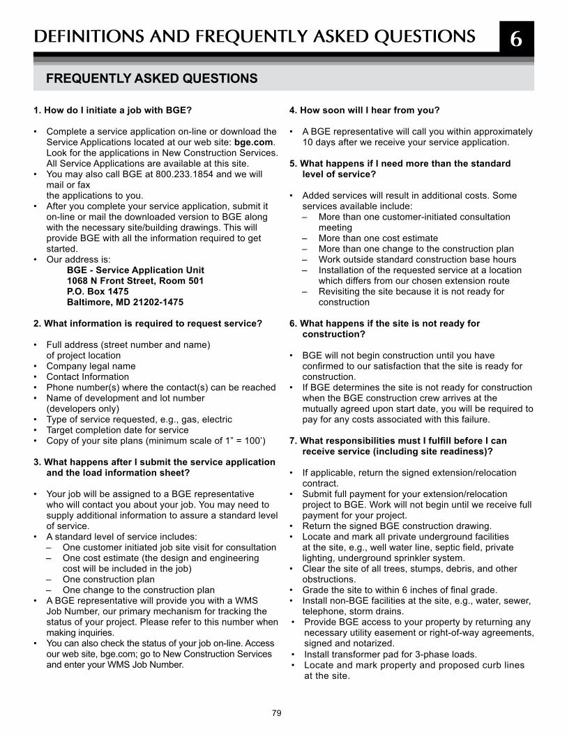
79
1. How do I initiate a job with BGE?
• Complete a service application on-line or download the Service Applications located at our web site: bge.com. Look for the applications in New Construction Services. All Service Applications are available at this site.
• You may also call BGE at 800.233.1854 and we will mail or fax the applications to you.
• After you complete your service application, submit it on-line or mail the downloaded version to BGE along with the necessary site/building drawings. This will provide BGE with all the information required to get started.
• Our address is: BGE - Service Application Unit1068 N Front Street, Room 501P.O. Box 1475Baltimore, MD 21202-1475
2. What information is required to request service?
• Full address (street number and name) of project location
• Company legal name • Contact Information• Phone number(s) where the contact(s) can be reached• Name of development and lot number
(developers only)• Type of service requested, e.g., gas, electric• Target completion date for service• Copy of your site plans (minimum scale of 1” = 100’)
3. What happens after I submit the service application and the load information sheet?
• Your job will be assigned to a BGE representative who will contact you about your job. You may need to supply additional information to assure a standard level of service.
• A standard level of service includes:– One customer initiated job site visit for consultation– One cost estimate (the design and engineering
cost will be included in the job)– One construction plan– One change to the construction plan
• A BGE representative will provide you with a WMS Job Number, our primary mechanism for tracking the status of your project. Please refer to this number when making inquiries.
• You can also check the status of your job on-line. Access our web site, bge.com; go to New Construction Services and enter your WMS Job Number.
4. How soon will I hear from you?
• A BGE representative will call you within approximately 10 days after we receive your service application.
5. What happens if I need more than the standard level of service?
• Added services will result in additional costs. Some services available include:– More than one customer-initiated consultation
meeting– More than one cost estimate– More than one change to the construction plan– Work outside standard construction base hours– Installation of the requested service at a location
which differs from our chosen extension route– Revisiting the site because it is not ready for
construction
6. What happens if the site is not ready for construction?
• BGE will not begin construction until you have confirmed to our satisfaction that the site is ready for construction.
• If BGE determines the site is not ready for construction when the BGE construction crew arrives at the mutually agreed upon start date, you will be required to pay for any costs associated with this failure.
7. What responsibilities must I fulfill before I can receive service (including site readiness)?
• If applicable, return the signed extension/relocation contract.
• Submit full payment for your extension/relocation project to BGE. Work will not begin until we receive full payment for your project.
• Return the signed BGE construction drawing.• Locate and mark all private underground facilities
at the site, e.g., well water line, septic field, private lighting, underground sprinkler system.
• Clear the site of all trees, stumps, debris, and other obstructions.
• Grade the site to within 6 inches of final grade.• Install non-BGE facilities at the site, e.g., water, sewer,
telephone, storm drains.• Provide BGE access to your property by returning any
necessary utility easement or right-of-way agreements, signed and notarized.
• Install transformer pad for 3-phase loads.• Locate and mark property and proposed curb lines
at the site.
6
FREQUENTLY ASKED QUESTIONS
DEFINITIONs AND FREqUENTLy AskED qUEsTIONs

80 81 81
• Coordinate with Verizon and CATV and other non-BGE utilities.
• Perform any other work reasonably required by us to provide satisfactory conditions for construction, or to assure compliance with the Maryland Public Service.
• Commission Electric and Gas Tariffs for Baltimore Gas and Electric and our construction standards.
• Ensure that the appropriate electrical and/or plumbing permit applications have been submitted to the local permitting agency for your building wiring and/or gas piping.
• Install approved meter protection where required at your cost.
• Ensure that areas around BGE facilities are free and clear of obstructions per BGE specifications.
8. I am thinking about building a deck onto my home or finishing my basement. How do I get a “ballpark estimate” to relocate the gas and/or electric service or meter to my house?
• Contact BGE at 800.233.1854. The call center representative will be able to provide an estimate for relocation of standard residential service lines. Or, you may call and request a service application. A BGE representative will contact you and calculate the estimated cost once we receive your completed service application.
9. How much notice does BGE need to install an underground gas or electric service to my new house?
• The entire process, which includes initiation, design, site readiness and construction, can take between 4 to 12 weeks depending on the scope of work, permitting requirements and weather conditions. For this reason, it is important to contact BGE by submitting a service application as early as possible in your planning process (e.g., permitting stage).
10. How do I upgrade or relocate my existing service?
• Electric– First, contact a licensed electrician. Your
electrician will obtain an electrical permit for wiring changes to your equipment.
– Second, submit a service application to BGE with a drawing reflecting the new gas/electric location for the relocated service.
– Third, your electrician will contact us to set up an appropriate order for changing your existing service. After your electrician has completed wiring changes, he will contact the electrical inspection department of your local jurisdiction for
inspection. When the wiring has been inspected and approved, the local jurisdictional inspection department will send us a certificate of approval. The certificate of approval ensures your job meets approved electrical codes. After BGE receives certification, we will complete your wiring connection at the meter. For safety precautions, we will require access to your panel box.
• Gas– First, contact a licensed plumber who
will obtain a permit with the plumbing inspection department.
– The second and third steps are the same as those for Electric.
11. What information do I need to check the status of a certificate?
• You will need your WMS Job Number, the job address, date the inspection occurred, and the electrical permit number, or, if gas, the plumbing permit number.
12. Does BGE install underground telephone and cable TV with their utilities?
• Yes, we often do. BGE has agreements with many of these service providers but you should contact your local provider and apply for service with them.
13. Can BGE supply street lighting or private area lighting for my project?
• BGE can provide a complete lighting system to meet your needs.
• For more information on BGE’s outdoor lighting program and available product line, please visit us at bge.com/outdoorlighting, or call us at 410.470.9446 or 800.685.0123.
14. If I am developing a new townhouse community, what consideration should I give to BGE for service and metering?
• You will need to pay close attention to "BGE’s Conditions of Supply and Location of Gas and Electric Meters” in this booklet. These areas detail what responsibilities you have in allowing adequate room for our gas and electric equipment.
• A BGE representative will work closely with you to ensure that the area dedicated to BGE metering is clearly agreed upon by you and BGE.
• Please provide BGE with any architectural drawings that you may have as early as possible.
• Final design drawing must be signed and returned to BGE before work will begin.
6
FREQUENTLY ASKED QUESTIONS (CONT'D)
DEFINITIONs AND FREqUENTLy AskED qUEsTIONs

81 81
NOTEs

82
NOTEs
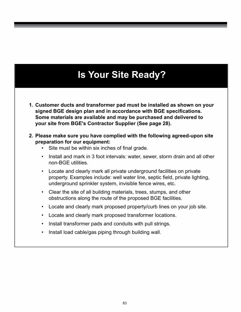
83
Is Your Site Ready?
1. Customer ducts and transformer pad must be installed as shown on your signed BGE design plan and in accordance with BGE specifications. Some materials are available and may be purchased and delivered to your site from BGE's Contractor Supplier (See page 28).
2. Please make sure you have complied with the following agreed-upon site preparation for our equipment:
• Site must be within six inches of final grade.• Install and mark in 3 foot intervals: water, sewer, storm drain and all other
non-BGE utilities.• Locate and clearly mark all private underground facilities on private
property. Examples include: well water line, septic field, private lighting, underground sprinkler system, invisible fence wires, etc.
• Clear the site of all building materials, trees, stumps, and other obstructions along the route of the proposed BGE facilities.
• Locate and clearly mark proposed property/curb lines on your job site.• Locate and clearly mark proposed transformer locations.• Install transformer pads and conduits with pull strings.• Install load cable/gas piping through building wall.
NOTEs

P.O. Box 1475Baltimore, Maryland 21203