Embed Size (px)
Citation preview
Natural Gas Compressor Station
Equipment Forms
These equipment forms are for natural gas compressor stations that are seeking a
Rule 13 permit and do not qualify for the general permit.
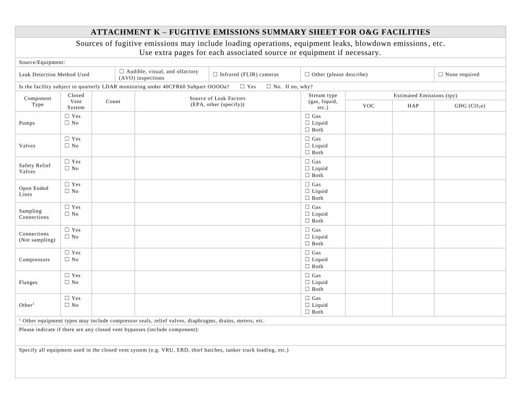
ATTACHMENT K – FUGITIVE EMISSIONS SUMMARY SHEET FOR O&G FACILITIES
Sources of fugitive emissions may include loading operations, equipment leaks, blowdown emissions , etc.
Use extra pages for each associated source or equipment if necessary. Source/Equipment:
Leak Detection Method Used ☐ Audible, visual, and olfactory
(AVO) inspections ☐ Infrared (FLIR) cameras ☐ Other (please describe) ☐ None required
Is the facility subject to quarterly LDAR monitoring under 40CFR60 Subpart OOOOa? ☐ Yes ☐ No. If no, why?
Component
Type
Closed
Vent System
Count Source of Leak Factors
(EPA, other (specify))
Stream type
(gas, liquid, etc.)
Estimated Emissions (tpy)
VOC HAP GHG (CO2e)
Pumps
☐ Yes
☐ No
☐ Gas
☐ Liquid
☐ Both
Valves
☐ Yes
☐ No
☐ Gas
☐ Liquid
☐ Both
Safety Relief Valves
☐ Yes
☐ No
☐ Gas
☐ Liquid
☐ Both
Open Ended
Lines
☐ Yes
☐ No
☐ Gas
☐ Liquid
☐ Both
Sampling
Connections
☐ Yes
☐ No
☐ Gas
☐ Liquid
☐ Both
Connections (Not sampling)
☐ Yes
☐ No
☐ Gas
☐ Liquid
☐ Both
Compressors
☐ Yes
☐ No
☐ Gas
☐ Liquid
☐ Both
Flanges
☐ Yes
☐ No
☐ Gas
☐ Liquid
☐ Both
Other1
☐ Yes
☐ No
☐ Gas
☐ Liquid
☐ Both
1 Other equipment types may include compressor seals, relief valves, diaphragms, drains, meters, etc.
Please indicate if there are any closed vent bypasses (include component):
Specify all equipment used in the closed vent system (e.g. VRU, ERD, thief hatches, tanker truck loading, etc.)
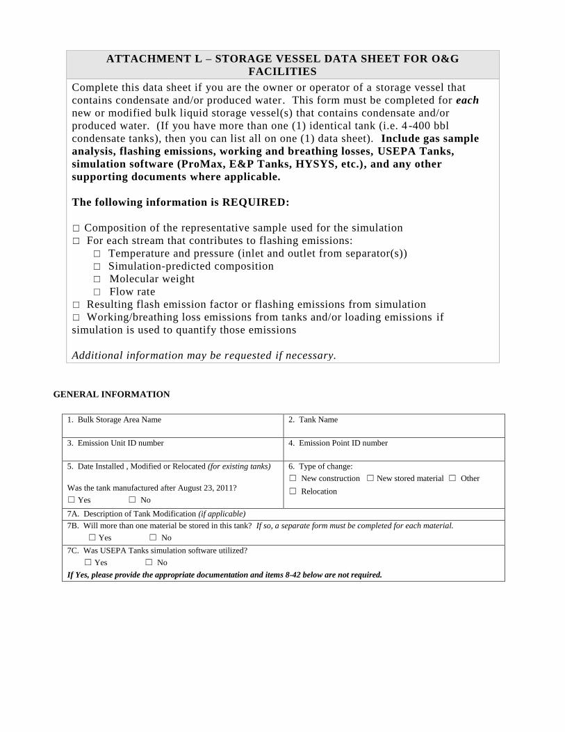
ATTACHMENT L – STORAGE VESSEL DATA SHEET FOR O&G
FACILITIES
Complete this data sheet if you are the owner or operator of a storage vessel that
contains condensate and/or produced water. This form must be completed for each
new or modified bulk liquid storage vessel(s) that contains condensate and/or
produced water. (If you have more than one (1) identical tank (i.e. 4 -400 bbl
condensate tanks), then you can list all on one (1) data sheet). Include gas sample
analysis, flashing emissions, working and breathing losses, USEPA Tanks,
simulation software (ProMax, E&P Tanks, HYSYS, etc.), and any other
supporting documents where applicable.
The following information is REQUIRED:
☐ Composition of the representative sample used for the simulation
☐ For each stream that contributes to flashing emissions:
☐ Temperature and pressure (inlet and outlet from separator(s))
☐ Simulation-predicted composition
☐ Molecular weight
☐ Flow rate
☐ Resulting flash emission factor or flashing emissions from simulation
☐ Working/breathing loss emissions from tanks and/or loading emissions if
simulation is used to quantify those emissions
Additional information may be requested if necessary.
GENERAL INFORMATION
1. Bulk Storage Area Name 2. Tank Name
3. Emission Unit ID number
4. Emission Point ID number
5. Date Installed , Modified or Relocated (for existing tanks)
Was the tank manufactured after August 23, 2011?
☐ Yes ☐ No
6. Type of change:
☐ New construction ☐ New stored material ☐ Other
☐ Relocation
7A. Description of Tank Modification (if applicable)
7B. Will more than one material be stored in this tank? If so, a separate form must be completed for each material.
☐ Yes ☐ No
7C. Was USEPA Tanks simulation software utilized?
☐ Yes ☐ No
If Yes, please provide the appropriate documentation and items 8-42 below are not required.
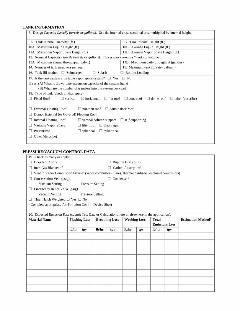
TANK INFORMATION
8. Design Capacity (specify barrels or gallons). Use the internal cross-sectional area multiplied by internal height.
9A. Tank Internal Diameter (ft.) 9B. Tank Internal Height (ft.)
10A. Maximum Liquid Height (ft.) 10B. Average Liquid Height (ft.)
11A. Maximum Vapor Space Height (ft.) 11B. Average Vapor Space Height (ft.)
12. Nominal Capacity (specify barrels or gallons). This is also known as “working volume”.
13A. Maximum annual throughput (gal/yr) 13B. Maximum daily throughput (gal/day)
14. Number of tank turnovers per year 15. Maximum tank fill rate (gal/min)
16. Tank fill method ☐ Submerged ☐ Splash ☐ Bottom Loading
17. Is the tank system a variable vapor space system? ☐ Yes ☐ No
If yes, (A) What is the volume expansion capacity of the system (gal)?
(B) What are the number of transfers into the system per year?
18. Type of tank (check all that apply):
☐ Fixed Roof ☐ vertical ☐ horizontal ☐ flat roof ☐ cone roof ☐ dome roof ☐ other (describe)
☐ External Floating Roof ☐ pontoon roof ☐ double deck roof
☐ Domed External (or Covered) Floating Roof
☐ Internal Floating Roof ☐ vertical column support ☐ self-supporting
☐ Variable Vapor Space ☐ lifter roof ☐ diaphragm
☐ Pressurized ☐ spherical ☐ cylindrical
☐ Other (describe)
PRESSURE/VACUUM CONTROL DATA
19. Check as many as apply:
☐ Does Not Apply ☐ Rupture Disc (psig)
☐ Inert Gas Blanket of _____________ ☐ Carbon Adsorption1
☐ Vent to Vapor Combustion Device1 (vapor combustors, flares, thermal oxidizers, enclosed combustors)
☐ Conservation Vent (psig) ☐ Condenser1
Vacuum Setting Pressure Setting
☐ Emergency Relief Valve (psig)
Vacuum Setting Pressure Setting
☐ Thief Hatch Weighted ☐ Yes ☐ No 1 Complete appropriate Air Pollution Control Device Sheet
20. Expected Emission Rate (submit Test Data or Calculations here or elsewhere in the application).
Material Name
Flashing Loss Breathing Loss Working Loss Total
Emissions Loss
Estimation Method1
lb/hr tpy lb/hr tpy lb/hr tpy lb/hr tpy
1 EPA = EPA Emission Factor, MB = Material Balance, SS = Similar Source, ST = Similar Source Test, Throughput Data, O = Other (specify)
Remember to attach emissions calculations, including TANKS Summary Sheets and other modeling summary sheets if applicable.
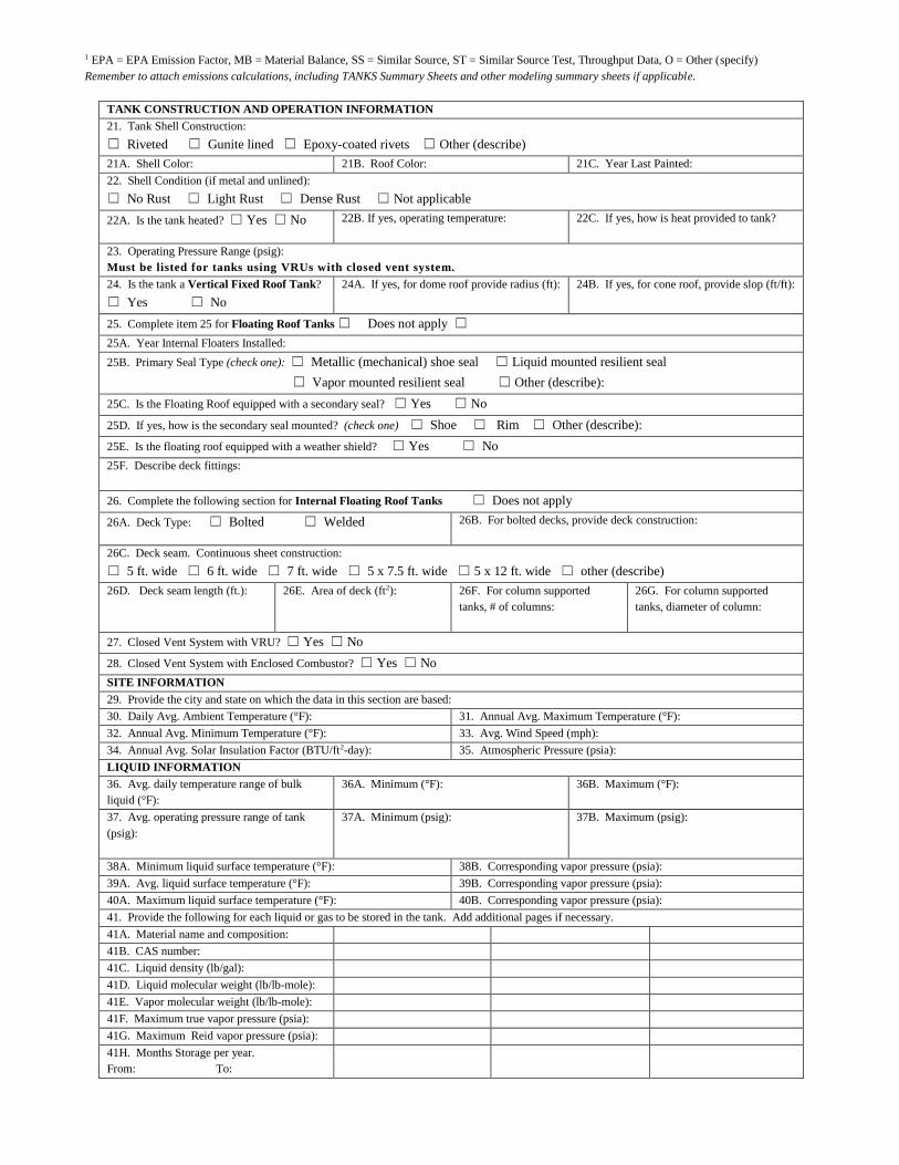
TANK CONSTRUCTION AND OPERATION INFORMATION
21. Tank Shell Construction:
☐ Riveted ☐ Gunite lined ☐ Epoxy-coated rivets ☐ Other (describe)
21A. Shell Color: 21B. Roof Color: 21C. Year Last Painted:
22. Shell Condition (if metal and unlined):
☐ No Rust ☐ Light Rust ☐ Dense Rust ☐ Not applicable
22A. Is the tank heated? ☐ Yes ☐ No 22B. If yes, operating temperature:
22C. If yes, how is heat provided to tank?
23. Operating Pressure Range (psig):
Must be listed for tanks using VRUs with closed vent system.
24. Is the tank a Vertical Fixed Roof Tank?
☐ Yes ☐ No
24A. If yes, for dome roof provide radius (ft):
24B. If yes, for cone roof, provide slop (ft/ft):
25. Complete item 25 for Floating Roof Tanks ☐ Does not apply ☐
25A. Year Internal Floaters Installed:
25B. Primary Seal Type (check one): ☐ Metallic (mechanical) shoe seal ☐ Liquid mounted resilient seal
☐ Vapor mounted resilient seal ☐ Other (describe):
25C. Is the Floating Roof equipped with a secondary seal? ☐ Yes ☐ No
25D. If yes, how is the secondary seal mounted? (check one) ☐ Shoe ☐ Rim ☐ Other (describe):
25E. Is the floating roof equipped with a weather shield? ☐ Yes ☐ No
25F. Describe deck fittings:
26. Complete the following section for Internal Floating Roof Tanks ☐ Does not apply
26A. Deck Type: ☐ Bolted ☐ Welded 26B. For bolted decks, provide deck construction:
26C. Deck seam. Continuous sheet construction:
☐ 5 ft. wide ☐ 6 ft. wide ☐ 7 ft. wide ☐ 5 x 7.5 ft. wide ☐ 5 x 12 ft. wide ☐ other (describe)
26D. Deck seam length (ft.):
26E. Area of deck (ft2):
26F. For column supported
tanks, # of columns:
26G. For column supported
tanks, diameter of column:
27. Closed Vent System with VRU? ☐ Yes ☐ No
28. Closed Vent System with Enclosed Combustor? ☐ Yes ☐ No
SITE INFORMATION
29. Provide the city and state on which the data in this section are based:
30. Daily Avg. Ambient Temperature (°F): 31. Annual Avg. Maximum Temperature (°F):
32. Annual Avg. Minimum Temperature (°F): 33. Avg. Wind Speed (mph):
34. Annual Avg. Solar Insulation Factor (BTU/ft2-day): 35. Atmospheric Pressure (psia):
LIQUID INFORMATION
36. Avg. daily temperature range of bulk
liquid (°F):
36A. Minimum (°F): 36B. Maximum (°F):
37. Avg. operating pressure range of tank
(psig):
37A. Minimum (psig): 37B. Maximum (psig):
38A. Minimum liquid surface temperature (°F): 38B. Corresponding vapor pressure (psia):
39A. Avg. liquid surface temperature (°F): 39B. Corresponding vapor pressure (psia):
40A. Maximum liquid surface temperature (°F): 40B. Corresponding vapor pressure (psia):
41. Provide the following for each liquid or gas to be stored in the tank. Add additional pages if necessary.
41A. Material name and composition:
41B. CAS number:
41C. Liquid density (lb/gal):
41D. Liquid molecular weight (lb/lb-mole):
41E. Vapor molecular weight (lb/lb-mole):
41F. Maximum true vapor pressure (psia):
41G. Maximum Reid vapor pressure (psia):
41H. Months Storage per year.
From: To:
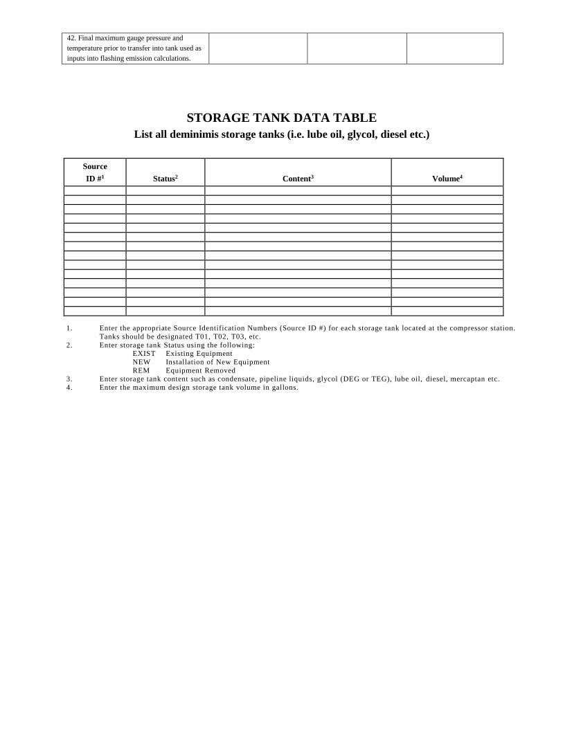
42. Final maximum gauge pressure and
temperature prior to transfer into tank used as
inputs into flashing emission calculations.
STORAGE TANK DATA TABLE
List all deminimis storage tanks (i.e. lube oil, glycol, diesel etc.)
Source
ID #1
Status2
Content3
Volume4
1. Enter the appropriate Source Identification Numbers (Source ID #) for each storage tank located at the compressor station.
Tanks should be designated T01, T02, T03, etc.
2. Enter storage tank Status using the following: EXIST Existing Equipment
NEW Installation of New Equipment
REM Equipment Removed 3. Enter storage tank content such as condensate, pipeline liquids, glycol (DEG or TEG), lube oil, diesel, mercaptan etc.
4. Enter the maximum design storage tank volume in gallons.
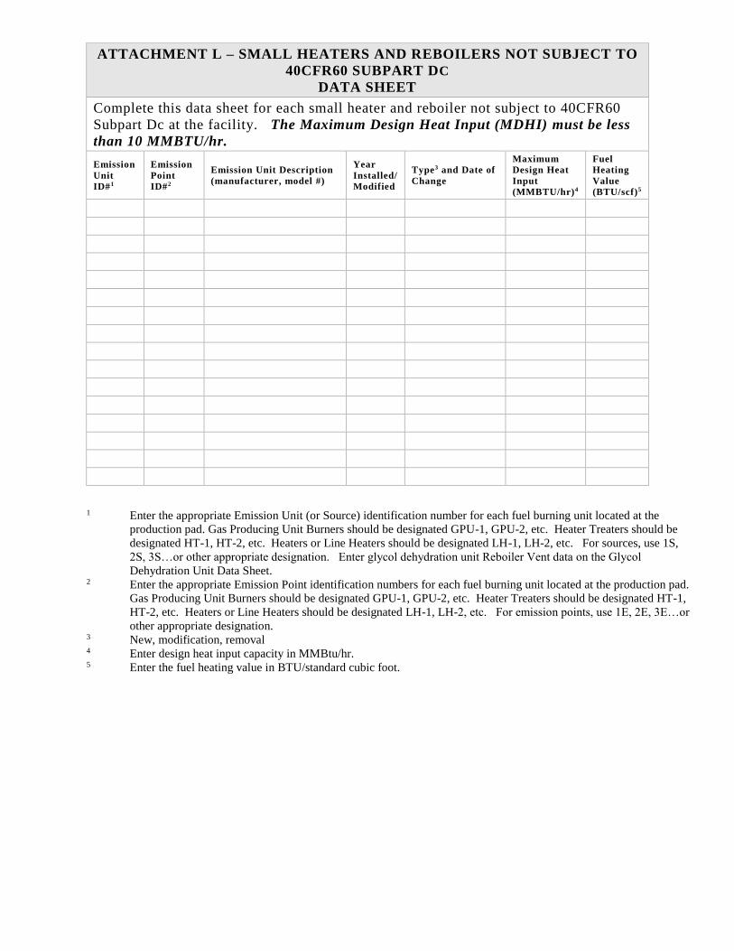
ATTACHMENT L – SMALL HEATERS AND REBOILERS NOT SUBJECT TO
40CFR60 SUBPART DC
DATA SHEET
Complete this data sheet for each small heater and reboiler not subject to 40CFR60
Subpart Dc at the facility. The Maximum Design Heat Input (MDHI) must be less
than 10 MMBTU/hr.
Emission
Unit
ID#1
Emission
Point
ID#2
Emission Unit Description
(manufacturer, model #)
Year
Installed/
Modified
Type3 and Date of
Change
Maximum
Design Heat
Input
(MMBTU/hr)4
Fuel
Heating
Value
(BTU/scf)5
1 Enter the appropriate Emission Unit (or Source) identification number for each fuel burning unit located at the
production pad. Gas Producing Unit Burners should be designated GPU-1, GPU-2, etc. Heater Treaters should be
designated HT-1, HT-2, etc. Heaters or Line Heaters should be designated LH-1, LH-2, etc. For sources, use 1S,
2S, 3S…or other appropriate designation. Enter glycol dehydration unit Reboiler Vent data on the Glycol
Dehydration Unit Data Sheet.
2 Enter the appropriate Emission Point identification numbers for each fuel burning unit located at the production pad.
Gas Producing Unit Burners should be designated GPU-1, GPU-2, etc. Heater Treaters should be designated HT-1,
HT-2, etc. Heaters or Line Heaters should be designated LH-1, LH-2, etc. For emission points, use 1E, 2E, 3E…or
other appropriate designation.
3 New, modification, removal
4 Enter design heat input capacity in MMBtu/hr.
5 Enter the fuel heating value in BTU/standard cubic foot.
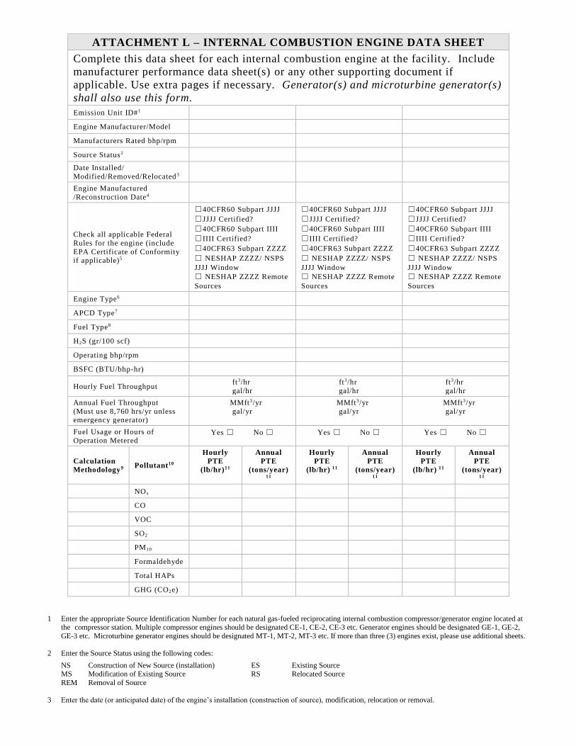
ATTACHMENT L – INTERNAL COMBUSTION ENGINE DATA SHEET
Complete this data sheet for each internal combustion engine at the facility. Include
manufacturer performance data sheet(s) or any other supporting document if
applicable. Use extra pages if necessary. Generator(s) and microturbine generator(s)
shall also use this form.
Emission Unit ID#1
Engine Manufacturer/Model
Manufacturers Rated bhp/rpm
Source Status2
Date Installed/
Modified/Removed/Relocated 3
Engine Manufactured
/Reconstruction Date4
Check all applicable Federal
Rules for the engine (include
EPA Certificate of Conformity if applicable)5
☐40CFR60 Subpart JJJJ
☐JJJJ Certified?
☐40CFR60 Subpart IIII
☐IIII Certified?
☐40CFR63 Subpart ZZZZ
☐ NESHAP ZZZZ/ NSPS
JJJJ Window
☐ NESHAP ZZZZ Remote
Sources
☐40CFR60 Subpart JJJJ
☐JJJJ Certified?
☐40CFR60 Subpart IIII
☐IIII Certified?
☐40CFR63 Subpart ZZZZ
☐ NESHAP ZZZZ/ NSPS
JJJJ Window
☐ NESHAP ZZZZ Remote
Sources
☐40CFR60 Subpart JJJJ
☐JJJJ Certified?
☐40CFR60 Subpart IIII
☐IIII Certified?
☐40CFR63 Subpart ZZZZ
☐ NESHAP ZZZZ/ NSPS
JJJJ Window
☐ NESHAP ZZZZ Remote
Sources
Engine Type6
APCD Type7
Fuel Type8
H2S (gr/100 scf)
Operating bhp/rpm
BSFC (BTU/bhp-hr)
Hourly Fuel Throughput ft3/hr
gal/hr ft3/hr
gal/hr ft3/hr
gal/hr
Annual Fuel Throughput
(Must use 8,760 hrs/yr unless
emergency generator)
MMft3/yr
gal/yr MMft3/yr
gal/yr
MMft3/yr
gal/yr
Fuel Usage or Hours of
Operation Metered Yes ☐ No ☐ Yes ☐ No ☐ Yes ☐ No ☐
Calculation
Methodology9 Pollutant10
Hourly
PTE
(lb/hr)11
Annual
PTE
(tons/year)
11
Hourly
PTE
(lb/hr) 11
Annual
PTE
(tons/year)
11
Hourly
PTE
(lb/hr) 11
Annual
PTE
(tons/year)
11
NOx
CO
VOC
SO2
PM10
Formaldehyde
Total HAPs
GHG (CO2e)
1 Enter the appropriate Source Identification Number for each natural gas-fueled reciprocating internal combustion compressor/generator engine located at the compressor station. Multiple compressor engines should be designated CE-1, CE-2, CE-3 etc. Generator engines should be designated GE-1, GE-2,
GE-3 etc. Microturbine generator engines should be designated MT-1, MT-2, MT-3 etc. If more than three (3) engines exist, please use additional sheets.
2 Enter the Source Status using the following codes:
NS Construction of New Source (installation) ES Existing Source MS Modification of Existing Source RS Relocated Source
REM Removal of Source
3 Enter the date (or anticipated date) of the engine’s installation (construction of source), modification, relocation or removal.
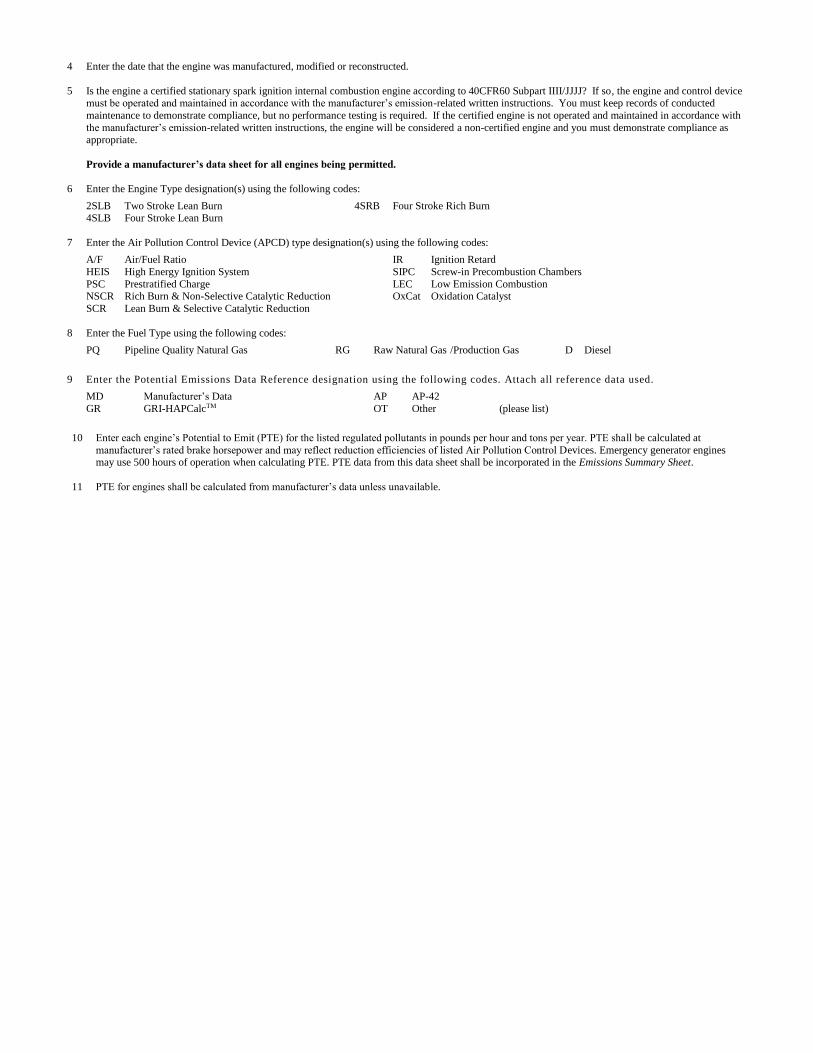
4 Enter the date that the engine was manufactured, modified or reconstructed.
5 Is the engine a certified stationary spark ignition internal combustion engine according to 40CFR60 Subpart IIII/JJJJ? If so, the engine and control device must be operated and maintained in accordance with the manufacturer’s emission-related written instructions. You must keep records of conducted
maintenance to demonstrate compliance, but no performance testing is required. If the certified engine is not operated and maintained in accordance with
the manufacturer’s emission-related written instructions, the engine will be considered a non-certified engine and you must demonstrate compliance as appropriate.
Provide a manufacturer’s data sheet for all engines being permitted.
6 Enter the Engine Type designation(s) using the following codes:
2SLB Two Stroke Lean Burn 4SRB Four Stroke Rich Burn 4SLB Four Stroke Lean Burn
7 Enter the Air Pollution Control Device (APCD) type designation(s) using the following codes:
A/F Air/Fuel Ratio IR Ignition Retard
HEIS High Energy Ignition System SIPC Screw-in Precombustion Chambers
PSC Prestratified Charge LEC Low Emission Combustion NSCR Rich Burn & Non-Selective Catalytic Reduction OxCat Oxidation Catalyst
SCR Lean Burn & Selective Catalytic Reduction
8 Enter the Fuel Type using the following codes:
PQ Pipeline Quality Natural Gas RG Raw Natural Gas /Production Gas D Diesel
9 Enter the Potential Emissions Data Reference designation using the following codes. Attach all reference data used.
MD Manufacturer’s Data AP AP-42
GR GRI-HAPCalcTM OT Other (please list)
10 Enter each engine’s Potential to Emit (PTE) for the listed regulated pollutants in pounds per hour and tons per year. PTE shall be calculated at
manufacturer’s rated brake horsepower and may reflect reduction efficiencies of listed Air Pollution Control Devices. Emergency generator engines may use 500 hours of operation when calculating PTE. PTE data from this data sheet shall be incorporated in the Emissions Summary Sheet.
11 PTE for engines shall be calculated from manufacturer’s data unless unavailable.
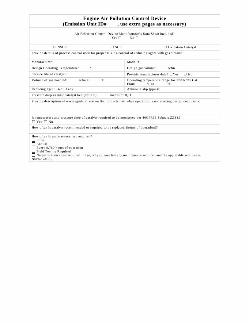
Engine Air Pollution Control Device
(Emission Unit ID# , use extra pages as necessary)
Air Pollution Control Device Manufacturer’s Data Sheet included?
Yes ☐ No ☐
☐ NSCR ☐ SCR ☐ Oxidation Catalyst
Provide details of process control used for proper mixing/control of reducing agent with gas stream:
Manufacturer: Model #:
Design Operating Temperature: oF Design gas volume: scfm
Service life of catalyst: Provide manufacturer data? ☐Yes ☐ No
Volume of gas handled: acfm at oF Operating temperature range for NSCR/Ox Cat:
From oF to oF
Reducing agent used, if any: Ammonia slip (ppm):
Pressure drop against catalyst bed (delta P): inches of H2O
Provide description of warning/alarm system that protects unit when operation is not meeting design conditions:
Is temperature and pressure drop of catalyst required to be monitored per 40CFR63 Subpart ZZZZ?
☐ Yes ☐ No
How often is catalyst recommended or required to be replaced (hours of operation)?
How often is performance test required?
Initial Annual
Every 8,760 hours of operation
Field Testing Required No performance test required. If so, why (please list any maintenance required and the applicable sections in
NSPS/GACT,
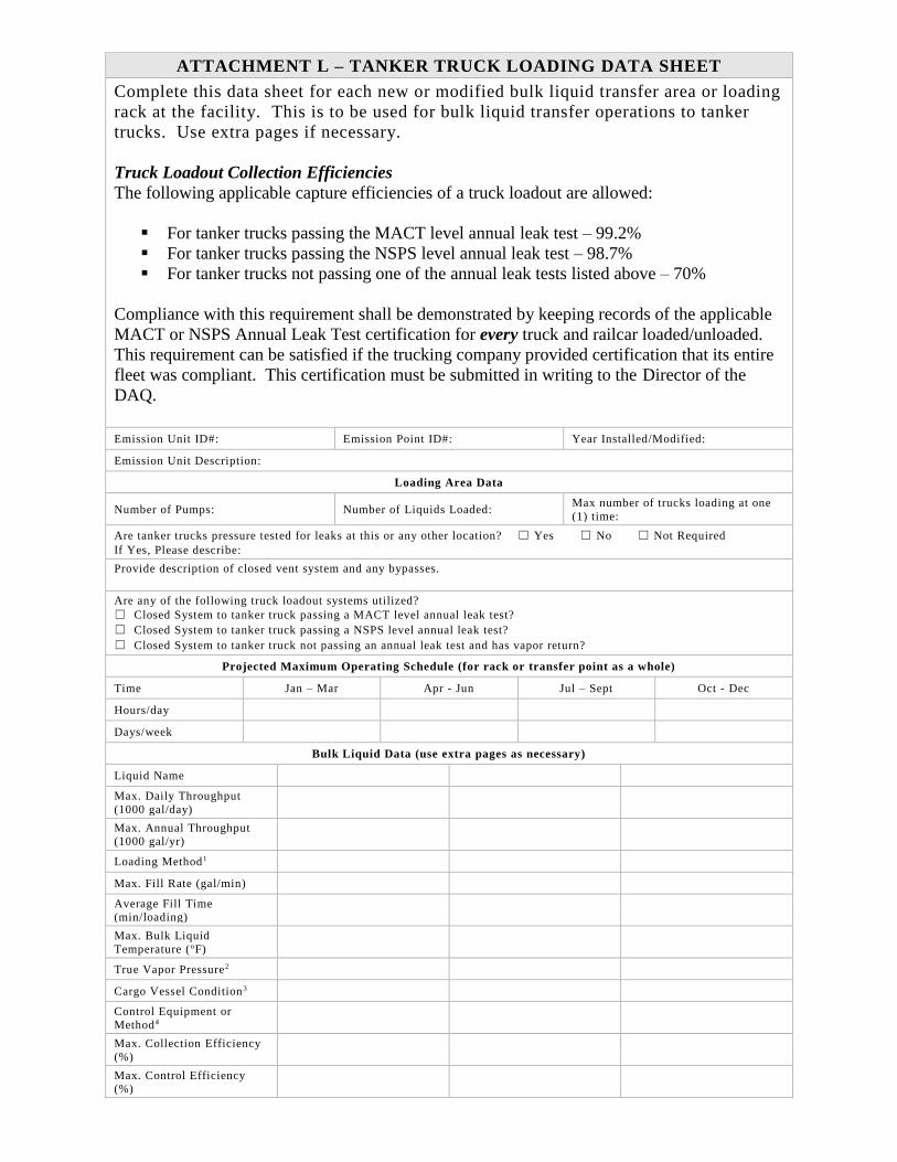
ATTACHMENT L – TANKER TRUCK LOADING DATA SHEET
Complete this data sheet for each new or modified bulk liquid transfer area or loading
rack at the facility. This is to be used for bulk liquid transfer operations to tanker
trucks. Use extra pages if necessary.
Truck Loadout Collection Efficiencies
The following applicable capture efficiencies of a truck loadout are allowed:
▪ For tanker trucks passing the MACT level annual leak test – 99.2%
▪ For tanker trucks passing the NSPS level annual leak test – 98.7%
▪ For tanker trucks not passing one of the annual leak tests listed above – 70%
Compliance with this requirement shall be demonstrated by keeping records of the applicable
MACT or NSPS Annual Leak Test certification for every truck and railcar loaded/unloaded.
This requirement can be satisfied if the trucking company provided certification that its entire
fleet was compliant. This certification must be submitted in writing to the Director of the
DAQ.
Emission Unit ID#: Emission Point ID#: Year Installed/Modified:
Emission Unit Description:
Loading Area Data
Number of Pumps: Number of Liquids Loaded: Max number of trucks loading at one
(1) time:
Are tanker trucks pressure tested for leaks at this or any other location? ☐ Yes ☐ No ☐ Not Required
If Yes, Please describe:
Provide description of closed vent system and any bypasses.
Are any of the following truck loadout systems utilized?
☐ Closed System to tanker truck passing a MACT level annual leak test?
☐ Closed System to tanker truck passing a NSPS level annual leak test?
☐ Closed System to tanker truck not passing an annual leak test and has vapor return?
Projected Maximum Operating Schedule (for rack or transfer point as a whole)
Time Jan – Mar Apr - Jun Jul – Sept Oct - Dec
Hours/day
Days/week
Bulk Liquid Data (use extra pages as necessary)
Liquid Name
Max. Daily Throughput
(1000 gal/day)
Max. Annual Throughput (1000 gal/yr)
Loading Method1
Max. Fill Rate (gal/min)
Average Fill Time
(min/loading)
Max. Bulk Liquid
Temperature (oF)
True Vapor Pressure2
Cargo Vessel Condition3
Control Equipment or
Method4
Max. Collection Efficiency
(%)
Max. Control Efficiency (%)
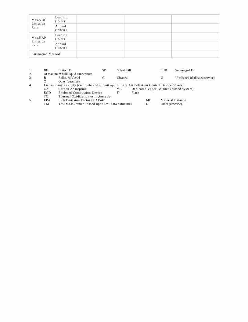
Max.VOC
Emission
Rate
Loading
(lb/hr)
Annual (ton/yr)
Max.HAP Emission
Rate
Loading
(lb/hr)
Annual
(ton/yr)
Estimation Method5
1 BF Bottom Fill SP Splash Fill SUB Submerged Fill 2 At maximum bulk liquid temperature
3 B Ballasted Vessel C Cleaned U Uncleaned (dedicated service)
O Other (describe) 4 List as many as apply (complete and submit appropria te Air Pollution Control Device Sheets)
CA Carbon Adsorption VB Dedicated Vapor Balance (closed system)
ECD Enclosed Combustion Device F Flare TO Thermal Oxidization or Incineration
5 EPA EPA Emission Factor in AP-42 MB Material Balance
TM Test Measurement based upon test data submittal O Other (describe)
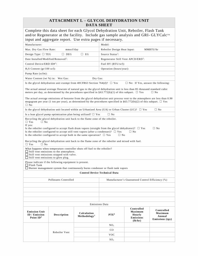
ATTACHMENT L – GLYCOL DEHYDRATION UNIT
DATA SHEET
Complete this data sheet for each Glycol Dehydration Unit, Reboiler, Flash Tank
and/or Regenerator at the facility. Include gas sample analysis and GRI- GLYCalcTM
input and aggregate report. Use extra pages if necessary.
Manufacturer: Model:
Max. Dry Gas Flow Rate: mmscf/day Reboiler Design Heat Input: MMBTU/hr
Design Type: ☐ TEG ☐ DEG ☐ EG Source Status1:
Date Installed/Modified/Removed 2: Regenerator Still Vent APCD/ERD3:
Control Device/ERD ID#3: Fuel HV (BTU/scf):
H2S Content (gr/100 scf): Operation (hours/year):
Pump Rate (scfm):
Water Content (wt %) in: Wet Gas: Dry Gas:
Is the glycol dehydration unit exempt from 40CFR63 Section 764(d)? ☐ Yes ☐ No: If Yes, answer the following:
The actual annual average flowrate of natural gas to the glycol dehydration unit is less than 85 thousand standard cubic
meters per day, as determined by the procedures specified in §63.772(b)(1) of this subpart. ☐ Yes ☐ No
The actual average emissions of benzene from the glycol dehydration unit process vent to the atmosphere are less than 0.90
megagram per year (1 ton per year), as determined by the procedures specified in §63.772(b)(2) of this subpart. ☐ Yes
☐ No
Is the glycol dehydration unit located within an Urbanized Area (UA) or Urban Cluster (UC)? ☐ Yes ☐ No
Is a lean glycol pump optimization plan being utilized? ☐ Yes ☐ No
Recycling the glycol dehydration unit back to the flame zone of the reboiler.
☐ Yes ☐ No
If yes:
Is the reboiler configured to accept flash drum vapors (straight from the glycol dehydrator)? ☐ Yes ☐ No
Is the reboiler configured to accept still vent vapors (after a condenser)? ☐ Yes ☐ No
Is the reboiler configured to accept both in the same operation? ☐ Yes ☐ No
Recycling the glycol dehydration unit back to the flame zone of the reboiler and mixed with fuel.
☐ Yes ☐ No
What happens when temperature controller shuts off fuel to the reboiler? Still vent emissions to the atmosphere.
Still vent emissions stopped with valve.
Still vent emissions to glow plug.
Please indicate if the following equipment is present. Flash Tank
Burner management system that continuously burns condenser or flash tank vapors
Control Device Technical Data
Pollutants Controlled Manufacturer’s Guaranteed Control Efficiency (%)
Emissions Data
Emission Unit
ID / Emission
Point ID4
Description Calculation
Methodology5 PTE6
Controlled
Maximum
Hourly
Emissions
(lb/hr)
Controlled
Maximum
Annual
Emissions (tpy)
Reboiler Vent
NOx
CO
VOC
SO2
PM10
GHG (CO2e)
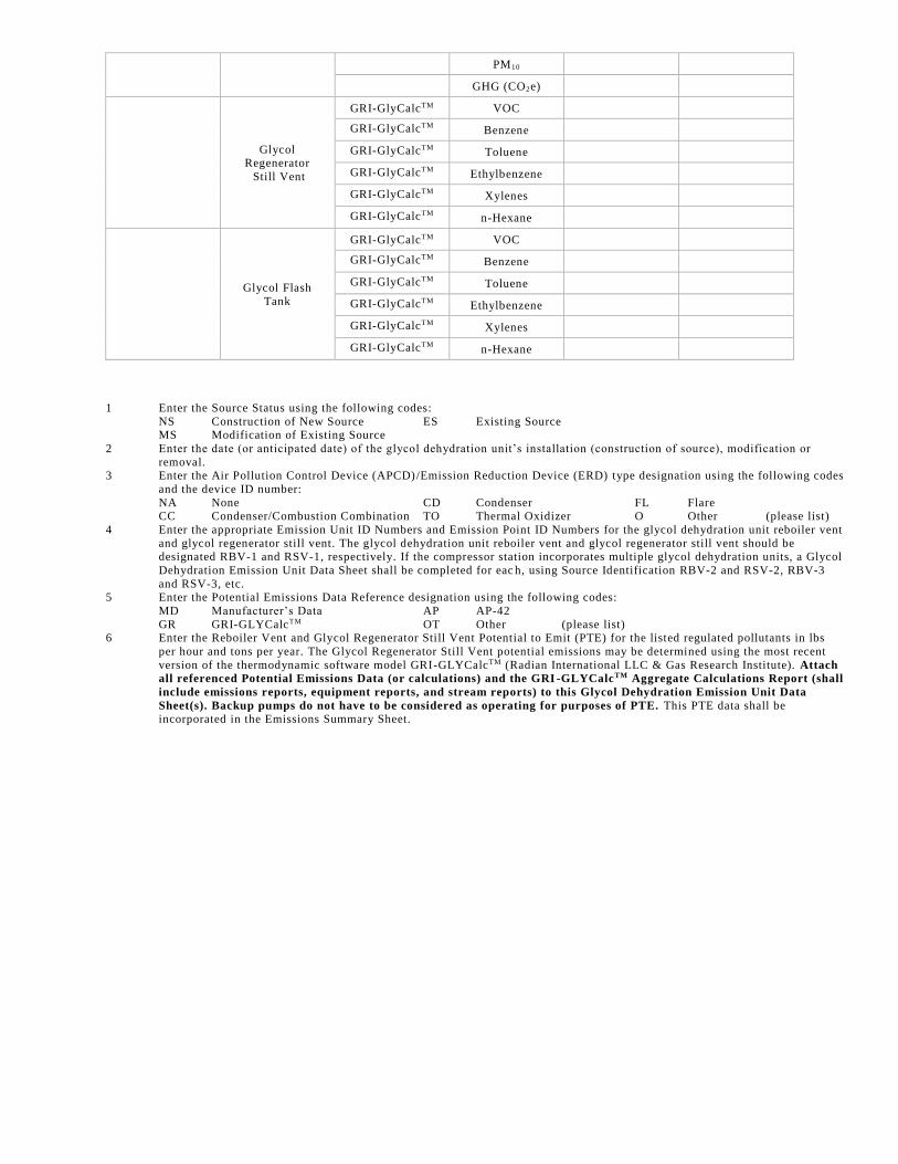
Glycol Regenerator
Still Vent
GRI-GlyCalcTM VOC
GRI-GlyCalcTM Benzene
GRI-GlyCalcTM Toluene
GRI-GlyCalcTM Ethylbenzene
GRI-GlyCalcTM Xylenes
GRI-GlyCalcTM n-Hexane
Glycol Flash
Tank
GRI-GlyCalcTM VOC
GRI-GlyCalcTM Benzene
GRI-GlyCalcTM Toluene
GRI-GlyCalcTM Ethylbenzene
GRI-GlyCalcTM Xylenes
GRI-GlyCalcTM n-Hexane
1 Enter the Source Status using the following codes:
NS Construction of New Source ES Existing Source MS Modification of Existing Source
2 Enter the date (or anticipated date) of the glycol dehydration unit’s installation (construction of source), modification or
removal. 3 Enter the Air Pollution Control Device (APCD)/Emission Reduction Device (ERD) type designation using the following codes
and the device ID number:
NA None CD Condenser FL Flare CC Condenser/Combustion Combination TO Thermal Oxidizer O Other (please list)
4 Enter the appropriate Emission Unit ID Numbers and Emission Point ID Numbers for the glycol dehydration unit reboiler vent
and glycol regenerator still vent. The glycol dehydration unit reboiler vent and glycol regenerator still vent should be designated RBV-1 and RSV-1, respectively. If the compressor station incorporates multiple glycol dehydration units, a Glycol
Dehydration Emission Unit Data Sheet shall be completed for eac h, using Source Identification RBV-2 and RSV-2, RBV-3
and RSV-3, etc. 5 Enter the Potential Emissions Data Reference designation using the following codes:
MD Manufacturer’s Data AP AP-42
GR GRI-GLYCalcTM OT Other (please list) 6 Enter the Reboiler Vent and Glycol Regenerator Still Vent Potential to Emit (PTE) for the listed regulated pollutants in lbs
per hour and tons per year. The Glycol Regenerator Still Vent potential emissions may be determined using the most recent
version of the thermodynamic software model GRI-GLYCalcTM (Radian International LLC & Gas Research Institute). Attach
all referenced Potential Emissions Data (or calculations) and the GRI -GLYCalcTM Aggregate Calculations Report (shall
include emissions reports, equipment reports, and stream reports) to this Glycol Dehydration Emission Unit Data
Sheet(s). Backup pumps do not have to be considered as operating for purposes of PTE. This PTE data shall be incorporated in the Emissions Summary Sheet.
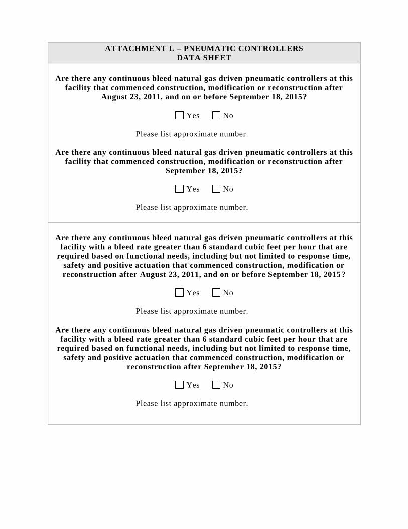
ATTACHMENT L – PNEUMATIC CONTROLLERS
DATA SHEET
Are there any continuous bleed natural gas driven pneumatic controllers at this
facility that commenced construction, modification or reconstruction after
August 23, 2011, and on or before September 18, 2015?
Yes No
Please list approximate number.
Are there any continuous bleed natural gas driven pneumatic controllers at this
facility that commenced construction, modification or reconstruction after
September 18, 2015?
Yes No
Please list approximate number.
Are there any continuous bleed natural gas driven pneumatic controllers at this
facility with a bleed rate greater than 6 standard cubic feet per hour that are
required based on functional needs, including but not limited to response time,
safety and positive actuation that commenced construction, modification or
reconstruction after August 23, 2011, and on or before September 18, 2015?
Yes No
Please list approximate number.
Are there any continuous bleed natural gas driven pneumatic controllers at this
facility with a bleed rate greater than 6 standard cubic feet per hour that are
required based on functional needs, including but not limited to response time,
safety and positive actuation that commenced construction, modification or
reconstruction after September 18, 2015?
Yes No
Please list approximate number.
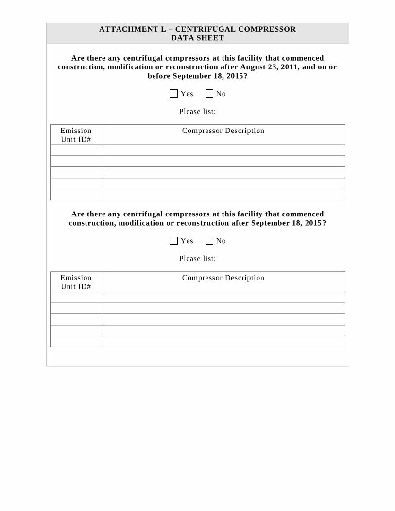
ATTACHMENT L – CENTRIFUGAL COMPRESSOR
DATA SHEET
Are there any centrifugal compressors at this facility that commenced
construction, modification or reconstruction after August 23, 2011, and on or
before September 18, 2015?
Yes No
Please list:
Emission
Unit ID#
Compressor Description
Are there any centrifugal compressors at this facility that commenced
construction, modification or reconstruction after September 18, 2015?
Yes No
Please list:
Emission
Unit ID#
Compressor Description
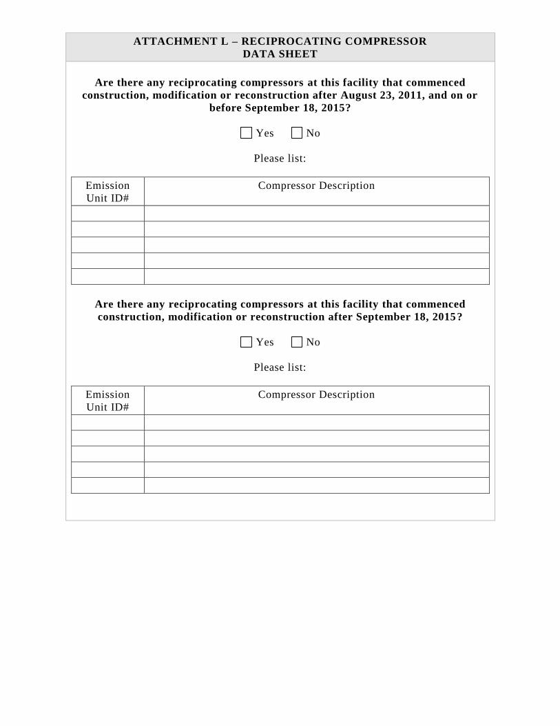
ATTACHMENT L – RECIPROCATING COMPRESSOR
DATA SHEET
Are there any reciprocating compressors at this facility that commenced
construction, modification or reconstruction after August 23, 2011, and on or
before September 18, 2015?
Yes No
Please list:
Emission
Unit ID#
Compressor Description
Are there any reciprocating compressors at this facility that commenced
construction, modification or reconstruction after September 18, 2015?
Yes No
Please list:
Emission
Unit ID#
Compressor Description
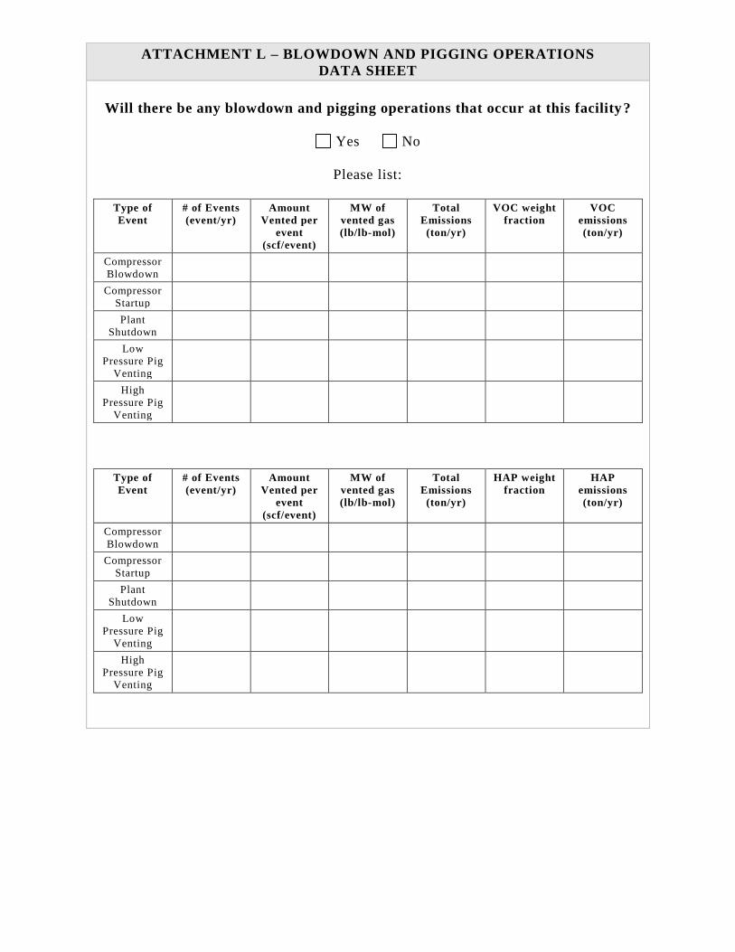
ATTACHMENT L – BLOWDOWN AND PIGGING OPERATIONS
DATA SHEET
Will there be any blowdown and pigging operations that occur at this facility?
Yes No
Please list:
Type of
Event
# of Events
(event/yr)
Amount
Vented per
event
(scf/event)
MW of
vented gas
(lb/lb-mol)
Total
Emissions
(ton/yr)
VOC weight
fraction
VOC
emissions
(ton/yr)
Compressor
Blowdown
Compressor
Startup
Plant
Shutdown
Low
Pressure Pig
Venting
High
Pressure Pig
Venting
Type of
Event
# of Events
(event/yr)
Amount
Vented per
event
(scf/event)
MW of
vented gas
(lb/lb-mol)
Total
Emissions
(ton/yr)
HAP weight
fraction
HAP
emissions
(ton/yr)
Compressor
Blowdown
Compressor
Startup
Plant
Shutdown
Low
Pressure Pig
Venting
High
Pressure Pig
Venting
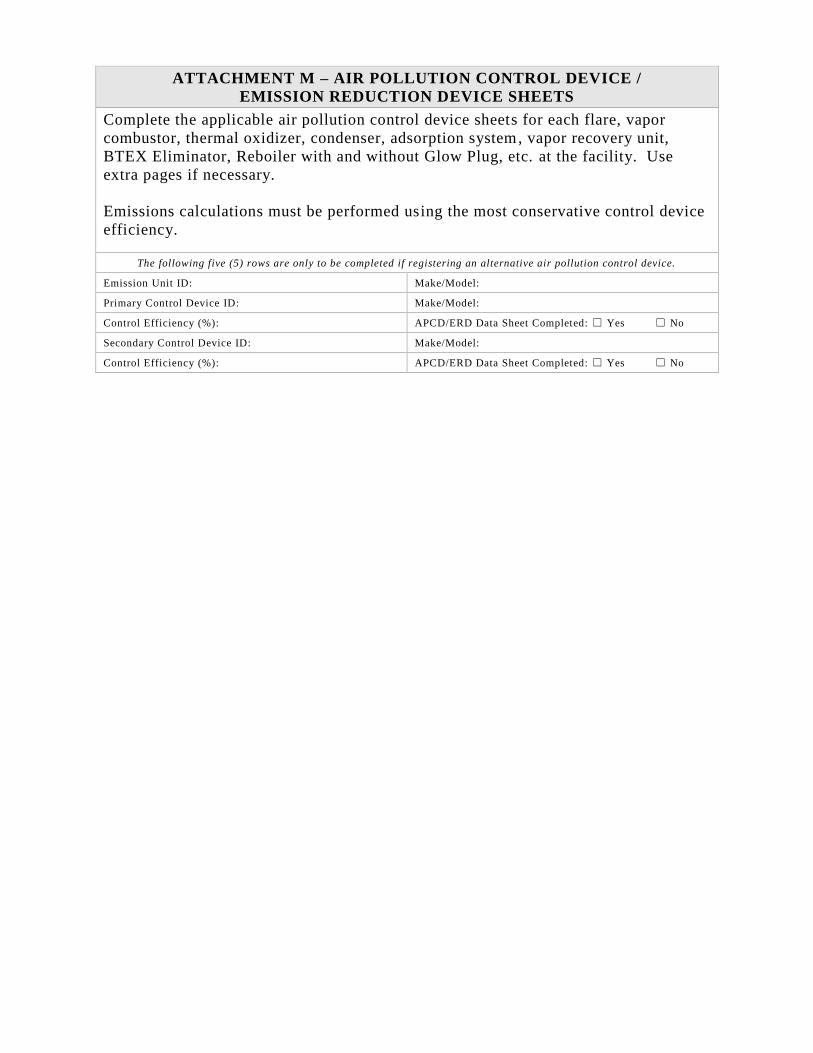
ATTACHMENT M – AIR POLLUTION CONTROL DEVICE /
EMISSION REDUCTION DEVICE SHEETS
Complete the applicable air pollution control device sheets for each flare, vapor
combustor, thermal oxidizer, condenser, adsorption system, vapor recovery unit,
BTEX Eliminator, Reboiler with and without Glow Plug, etc. at the facility. Use
extra pages if necessary.
Emissions calculations must be performed using the most conservative control device
efficiency.
The following five (5) rows are only to be completed if registering an alternative air pollution control device.
Emission Unit ID: Make/Model:
Primary Control Device ID: Make/Model:
Control Efficiency (%): APCD/ERD Data Sheet Completed: ☐ Yes ☐ No
Secondary Control Device ID: Make/Model:
Control Efficiency (%): APCD/ERD Data Sheet Completed: ☐ Yes ☐ No
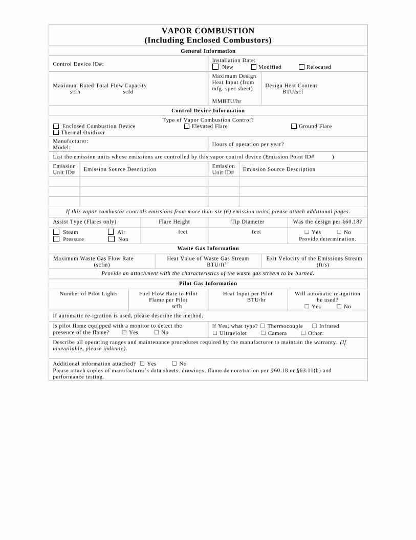
VAPOR COMBUSTION
(Including Enclosed Combustors)
General Information
Control Device ID#: Installation Date:
New Modified Relocated
Maximum Rated Total Flow Capacity scfh scfd
Maximum Design Heat Input (from
mfg. spec sheet)
MMBTU/hr
Design Heat Content BTU/scf
Control Device Information
Type of Vapor Combustion Control? Enclosed Combustion Device Elevated Flare Ground Flare
Thermal Oxidizer
Manufacturer:
Model: Hours of operation per year?
List the emission units whose emissions are controlled by this vapor control device (Emission Point ID# )
Emission Unit ID#
Emission Source Description Emission Unit ID#
Emission Source Description
If this vapor combustor controls emissions from more than six (6) emission units, please attach additional pages.
Assist Type (Flares only) Flare Height Tip Diameter Was the design per §60.18?
Steam Air
Pressure Non
feet feet ☐ Yes ☐ No
Provide determination.
Waste Gas Information
Maximum Waste Gas Flow Rate (scfm)
Heat Value of Waste Gas Stream BTU/ft3
Exit Velocity of the Emissions Stream (ft/s)
Provide an attachment with the characteristics of the waste gas stream to be burned.
Pilot Gas Information
Number of Pilot Lights
Fuel Flow Rate to Pilot Flame per Pilot
scfh
Heat Input per Pilot BTU/hr
Will automatic re-ignition be used?
☐ Yes ☐ No
If automatic re-ignition is used, please describe the method.
Is pilot flame equipped with a monitor to detect the
presence of the flame? ☐ Yes ☐ No
If Yes, what type? ☐ Thermocouple ☐ Infrared
☐ Ultraviolet ☐ Camera ☐ Other:
Describe all operating ranges and maintenance procedures required by the manufacturer to maintain the warranty. (If
unavailable, please indicate).
Additional information attached? ☐ Yes ☐ No
Please attach copies of manufacturer’s data sheets, drawings, flame demonstration per §60.18 or §63.11(b) and
performance testing.
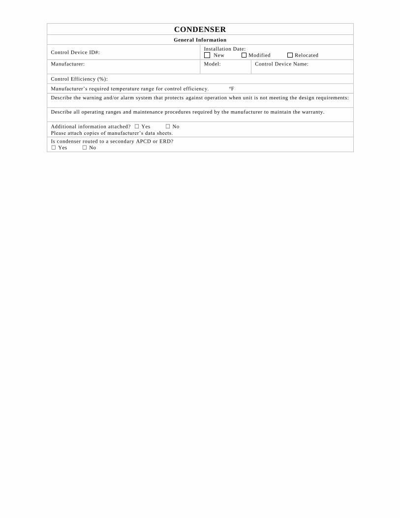
CONDENSER
General Information
Control Device ID#: Installation Date:
New Modified Relocated
Manufacturer:
Model:
Control Device Name:
Control Efficiency (%):
Manufacturer’s required temperature range for control efficiency. oF
Describe the warning and/or alarm system that protects against operation when unit is not meeting the design requirements:
Describe all operating ranges and maintenance procedures required by the manufacturer to maintain the warranty.
Additional information attached? ☐ Yes ☐ No
Please attach copies of manufacturer’s data sheets.
Is condenser routed to a secondary APCD or ERD?
☐ Yes ☐ No
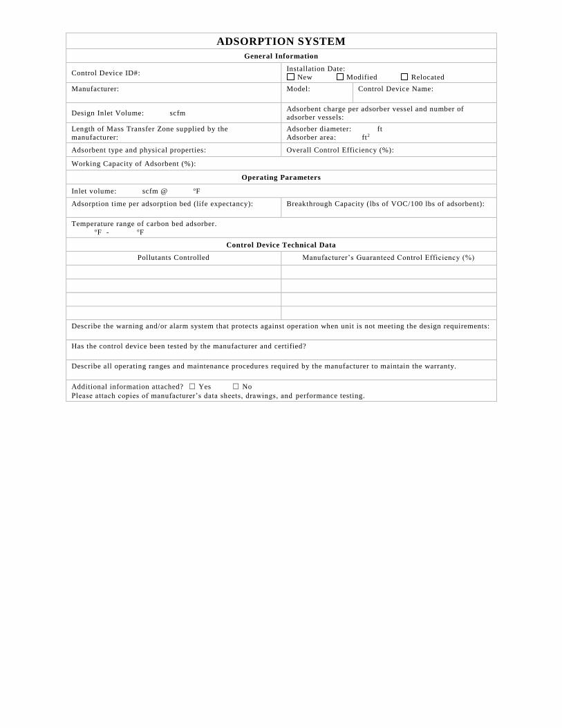
ADSORPTION SYSTEM
General Information
Control Device ID#: Installation Date:
New Modified Relocated
Manufacturer:
Model:
Control Device Name:
Design Inlet Volume: scfm Adsorbent charge per adsorber vessel and number of adsorber vessels:
Length of Mass Transfer Zone supplied by the
manufacturer:
Adsorber diameter: ft
Adsorber area: ft2
Adsorbent type and physical properties: Overall Control Efficiency (%):
Working Capacity of Adsorbent (%):
Operating Parameters
Inlet volume: scfm @ oF
Adsorption time per adsorption bed (life expectancy):
Breakthrough Capacity (lbs of VOC/100 lbs of adsorbent):
Temperature range of carbon bed adsorber.
oF - oF
Control Device Technical Data
Pollutants Controlled Manufacturer’s Guaranteed Control Efficiency (%)
Describe the warning and/or alarm system that protects against operation when unit is not meeting the design requirements:
Has the control device been tested by the manufacturer and certified?
Describe all operating ranges and maintenance procedures required by the manufacturer to maintain the warranty.
Additional information attached? ☐ Yes ☐ No
Please attach copies of manufacturer’s data sheets, drawings, and performance testing.
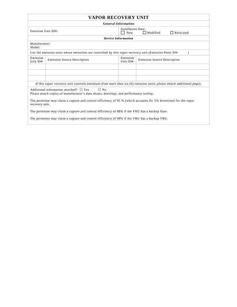
VAPOR RECOVERY UNIT
General Information
Emission Unit ID#: Installation Date:
New Modified Relocated
Device Information
Manufacturer:
Model:
List the emission units whose emissions are controlled by this vapor recovery unit (Emission Point ID# )
Emission Unit ID#
Emission Source Description Emission Unit ID#
Emission Source Description
If this vapor recovery unit controls emissions from more than six (6) emission units, please attach additional pages.
Additional information attached? ☐ Yes ☐ No
Please attach copies of manufacturer’s data sheets, drawings, and performance testing.
The permittee may claim a capture and control efficiency of 95 % (which accounts for 5% downtime) for the vapor
recovery unit.
The permittee may claim a capture and control efficiency of 98% if the VRU has a backup flare .
The permittee may claim a capture and control efficiency of 98% if the VRU has a backup VRU.