Embed Size (px)
Citation preview

2008inGAPInnovative Natural Gas Processes and Products P.O. box 1033 Blindern0317 OsloNorway
Phone: +47 22 85 55 35Fax: +47 22 85 54 41
desi
gn |
easy
.no
ANN
UAL R
EPO
RT

Resume The inGAP centre of Innovative Natural Gas Processes and Products was of-ficially launched on March 19, 2007. During the first year, focus was set on building the organization and laying the basis for later achievements through construction of in-situ characterization installations, especially at the Swiss-Norwegian beamline at ESRF, Grenoble, and through development of impor-tant techniques such as 3D-TEM and powder ALD. In 2008, the new equipment has been set into use, focusing in particular on three processes of special interest to the industry partners: The Fischer-Tropsch process, the Methanol-to-olefins process and the Olefins technology process. In addition, an activity was initiated in the New chemistry area, focusing on metal-organic framework compounds with potential for catalytic applications.
Portraits which inGAP personnel made of each other during the first inGAP seminar.
2

Centre vision •Valuecreationinnatural-gasprocessesthroughrationaldesignof
processes and products based on atomistic and mechanistic insight in catalyst and reactor parameters under operative conditions
Main challenges•Toestablishawell-functioningframeworktostudycatalyticprocessesin
a cross-disciplinary manner
•Toattracthighlyqualifiedscientistsandstudentstoworkinthecentre
Centre goals•Toprovideadvancedmethodologyandfundamentalinsightintocatalyst
technology to industry partners, thereby promoting higher productivity in existing plants, a systematic approach to development of improved cata-lysts and processes and the basis for creating new natural gas processes and products
•Fundingandresearchtrainingofatleast18PhDstudentsand10-12temporary researchers during an 8 year period
•Atleast80publicationsinhigh-rankedjournals,and80oralandposterpresentations at conferences
•HostinganInternationalSchoolofCatalysis
•Personnelexchange(8man-years)betweenindustry,instituteandaca-demia
•Anumberofpatentapplications
3

Managing Director
Research plan/strategyinGAP’s strategy is to establish a cross-disciplinary centre that integrates experiments, theory and technology within the field of catalytic processes.
Industrial catalysts comprise several length scales and levels of complexity; active sites possibly being influenced by promoters (modifiers), possiblyinteractingwiththesupport(orframework),allbeingincorporated into a formulated matrix. The very type of activesite(acidic,metal,redox),promoters,supports(high surface, porous, crystalline, basic), binders isstrongly process dependent. Therefore the present
focus is on systems of particular relevance for natural gas processes; i.e., metal-support catalysts and microporous catalysts.
Each industry partner has defined a process of particular interest to them, and identified technical challenges in these processes which are addressed on a fundamental level in joint industry-institute-academia projects. To supporttheprojectsthatdirectlyaddresseachoftheseprocesses,severalfundamentalprojectshavebeendefinedaddressingtopicssuchassynthesisofmodelmaterialsand methods development. Further, investments are made in instruments and equipment of particular importance for the study of each of the processes.
AmajorgoalofinGAPistomergethevariousactivitiesandpartnerexpertiseinto a common pool of knowledge. Therefore, the management team has a special responsibility of disseminating important achievements, especially on themethodologyside,betweentheprojects.
After nearly two years of operation, inGAP is well on track towards our overall goals.
photo © Morten Brakestad
4

Table of contents
ORGANISATION ......................................................... 6
SCIENTIFIC ACTIVITIES AND RESULTS ....................... 9NATURAL GAS TO SYNGAS ..................................... 10NATURAL GAS TO FUELS ....................................... 12NATURAL GAS TO PETROCHEMICALS .................... 24NEW CHEMISTRY ................................................. 39METHODS ............................................................ 40
INTERNATIONAL COLLABORATION ......................... 41
RECRUITMENT .......................................................... 42
COMMUNICATION ................................................... 42
SUPPLEMENTS .......................................................... 43
FINANCING ............................................................... 48
PUBLICATIONS .......................................................... 51
5

ORGANISATION Organisation structureTheinGAPcentreisorganisedthroughaprojectbasedmatrix.Eachprojecthasbeenallocatedto an Innovation Area, with an Innovation Area Manager. The Areas are:
•NG(NaturalGas)tosyngas•NGtofuels•NGtopetrochemicals•Newchemistry•Methods
The Innovation Area Managers are part of inGAP’s management team, together with the Managing Director and the Administrative Leader. The Innovation Area Managers report to the Managing Director. In order to reduce the number of persons involved in management tasks, and for the Innovation Area Managers to have “hands-on” knowledge of their area, all theManagersarealsoprojectleadersofaprojectwithintheirgiveninnovationarea.
TherearetwotypesofprojectswithininGAP:
EachindustrypartnerhasdefinedaRestrictedTechnologyArea(RTA)project,forwhich1. theyaregivenprioritytointellectualpropertyrights(IPR).
Non-RTAprojects,whichareofglobalinteresttotheCentrepartners,mainlyfocusing2. on method development as well as preparation, characterization and testing of model materials.
ORGANISATION
Steering Board Board leader: Erling Rytter
NG to syngasLeader: Bjørnar Arstad
NG to fuelsLeader: Morten Rønnekleiv
New chemistryLeader: Edd Blekkan
MethodsLeader: Poul Norby
NG to petrochemicalsLeader: Richard Blom
InternationalAdvisory Board
Management teamManaging Director: Unni Olsbye
Administrator: Søren Jakcobsen /Sigurd Brændeland
6

The inGAP Steering Board had the following members in 2008:
AnInternationalAdvisoryBoard(IAB)hasbeenappointedfrom01/2008,foraperiodof2years. Each Advisor covers a research area closely related to inGAPs main activities. The IAB consistsofthefollowingpersonsduring2008-2009(inalphabeticalorder):
•Prof.FerdiSchüth,Max-Planckinstitute(Nanomaterials)
•Prof.GaborSomorjai,Univ.California(Surfacecharacterization)
•Prof.BertWeckhuysen,Univ.Utrecht(Insitucharacterization)
The IAB assists the Steering Board in evaluating activities and recommending long-term strategies and priorities.
The Steering Board has members from each of the consortium partners and has the overall responsibility for all inGAPs activities. The Board Leader is appointed for 2 years at a time and fortheyears2007-2008theBoardLeaderisErlingRytter(StatoilHydro).
Partner Representative Deputy
UiO Helmer Fjellvåg Anders Elverhøi
NTNU Anders Holmen Edd Blekkan
SINTEF Aage Stori Duncan Akporiaye
StatoilHydro Erling Rytter Morten Rønnekleiv
INEOS ChlorVinyls Steinar Kvisle Terje Fuglerud
Borealis Klaus-Joachim Jens Eberhard Dreher
7

Partners inGAP is a consortium between the following partners:
Hostinstitution:
•UniversityofOslo(UiO)
Industry:
•StatoilHydroASA•INEOSChlorVinyls•Borealis
Non-industry:
•NorgesTekniske-NaturvitenskapeligeUniversitet(NTNU)•SINTEF
From01/2009theDanishcatalystmanufacturercompanyHaldorTopsøeAS(HTAS)willjointheconsortiumasindustrypartner.
Partner CollaborationPartner collaboration in inGAP is ensured by three elements:
Project collaboration. One very important goal for inGAP is to combine the partners’ expertise and knowledge to advance understanding on selected processes. To achieve this goalallinnovationareasandmostprojectsinvolveseveralpartners.Inthiswaytransferofcompetence between partners is assured and, hence, a united centre accomplished.
Personnel exchange. All Ph.D. students employed within the centre will spend 6 months in one of the industry partners’ research facilities. Since the exchange takes place in the last part of the Ph.D. program, the industry partner gets a highly skilled chemist in the laboratory and one that has been working on problems related to that partner’s processes. At the same time this gives the student a chance to experience the challenges in high scale production chemistry and boost motivation even further.
Internal seminars. Two inGAP seminars were organized in 2008. The first inGAP seminar took place in April, with a foremost aim of making personal contacts and sharing inGAP’s vision with all centre members. The second seminar was organized in November. In addition to making personal contacts and sharing inGAP’s vision, the aim of the second seminar was extended to disseminating recent project results by oral and poster presentations,being scientifically inspired by plenary lectures by our international scientific advisors, and discussing the further strategy of the centre for reaching our overall goal.
8

SCIENTIFIC ACTIVITIES AND RESULTS
inGAP’s vision can be shortened to: “Innovation through fundamental insight”. In catalysis, the workhorse of petrochemical industry, fundamental insight is primarily met by studies of well-defined catalysts under working conditions, so-called Operando or in-situ characterization, in combination with mechanistic and kinetic reaction studies as well as quantum-chemical modeling. One prerequisite of fundamental insight is thus to have access to operando equipment as well as in-house expertise in the use of such equipment.
In2007,amajorgoalofinGAPwastoinstallfeedsystemsandeffluentanalysisunitsforcharacterization equipment in in-house laboratories as well as at the ESRF synchrotron (Swiss-Norwegianbeamline)inGrenoble,France.In2008,thisequipmenthasbeenputinto use, and focus was set on two processes for which inGAP personnel has the widest experience: The Fischer-Tropsch and Methanol-to-Olefins reactions. Results from such studiesarereportedbelow,togetherwithaselectionofresultsobtainedinotherprojects.
Anoverviewofthemethodsinstalledand/ordevelopedinthecentreduring2007-2008isshown at the end of this chapter.
SCIENTIFIC ACTIVITIES AND RESULTS
An aerial view of the European Synchrotron Radiation facility in Grenoble.
9

Sorption enhanced steam methane reforming (SE-SMR)
Fossilfuelsarelikelytocontinuetobeamajorenergysourcein the near future and techniques for reducing greenhouse gas emissions while still producing energy from such sources should be implemented. During the last years a process termed sorption-enhanced methane steam reforming (SE-SMR) has gained increased attention as a potentialeconomical, favorable process for hydrogen production with simultaneouscaptureofCO2 [1, 2 and references therein]. The produced hydrogen may be used directly for power generation or, after more purification, in e.g. PEM fuel cells. SE-SMR is carried out catalytically with a co-present sorbent powder in the reactor.Central equations for the SE-SMRprocess are given below.
CH4(g)+H2O(g)CO(g)+3H2(g)Reforming(1)
CO(g)+H2O(g)CO2(g)+H2(g)Water-gasshift(2)
MO(s)+CO2(g)MCO3(s)Sorption(3) (MO=metaloxide) CH4(g)+2H2O(g)+MOMCO3(s)+4H2(g)Overall(4)
SE-SMR takes place at temperatures around 600 °Cor lower. Equations 1 and 2 describe the catalytic transformation (reforming) of methane and water intoCO,CO2 and hydrogen. Equation 3, which takes place simultaneously with 1 and 2, describes the reaction between CO2 and the sorbent leading to a carbonate compound. Due to reaction 3, reactions 1 and 2 are driven towards right/products according to standardchemical equilibrium principles. The reverse of eq. 3 describes regeneration of the sorbent, which is typically carriedoutat850-950°Cdependingstronglyonmaterialtype,kinetics,andpartialpressureofCO2 in the reactor. Eq. 4 describes the sum of reactions that take place in the reformer reactor in the SE-SMR reaction. The
thermodynamic equilibrium for most investigated SE-SMR systems indicates that around 98 % hydrogen may be formed, with the rest being unconverted methane [1].
So far only separate parts of the SE-SMR process have been tested and reported in the open literature. The present Project has been focused on developing andbuildingalab-scalecirculatingfluidizedbed(CFB)reactorfor demonstrating continuous hydrogen production by sorption enhanced steam methane reforming. Figure 1 below shows the principle of the process, the lab reactor we completed during 2008. The catalyst used in the present work was a 60wt.%NiO/NiAl2O4 which was reduced in hydrogen before use. The sorbent used in the presentworkwasbasedonnaturaldolomitefromSeljeliin northern Norway due to its availability, low price, and goodquality(limitedamountofsulphuramongothers).Beforeuse,thedolomitewasheattreatedat900°Cfor6hoursin10%H2/90%N2. Thereafter a measured amount of catalyst and sorbent was mixed in a volumetric ratio of 20vol.%:80vol.% (catalyst:sorbent) before introductioninto the reactor system. In our experiments the SE-SMR reaction (eq. 1-3, 4) took place around 600 °Cand theregeneration(reverseofeq.3)of sorbent tookplace around 910 °C. The feed into the reformer wasmethane and steam in a 1:4 ratio. Other gas flows into the reactor system for loop seal, riser and regenerator were nitrogen.
Figure2shows theCO2 separation efficiency, which is defined as the amount of CO2 leaving the regenerator relative to the maximum possible theoretical amount. InthisexperimenttheefficiencyofCO2 separation was roughly around 60-65% on average. Since the efficiency should preferably be higher we are currently developing
NATURAL GAS TO SYNGASN
ATU
RAL G
AS TO
SYN
GAS
10
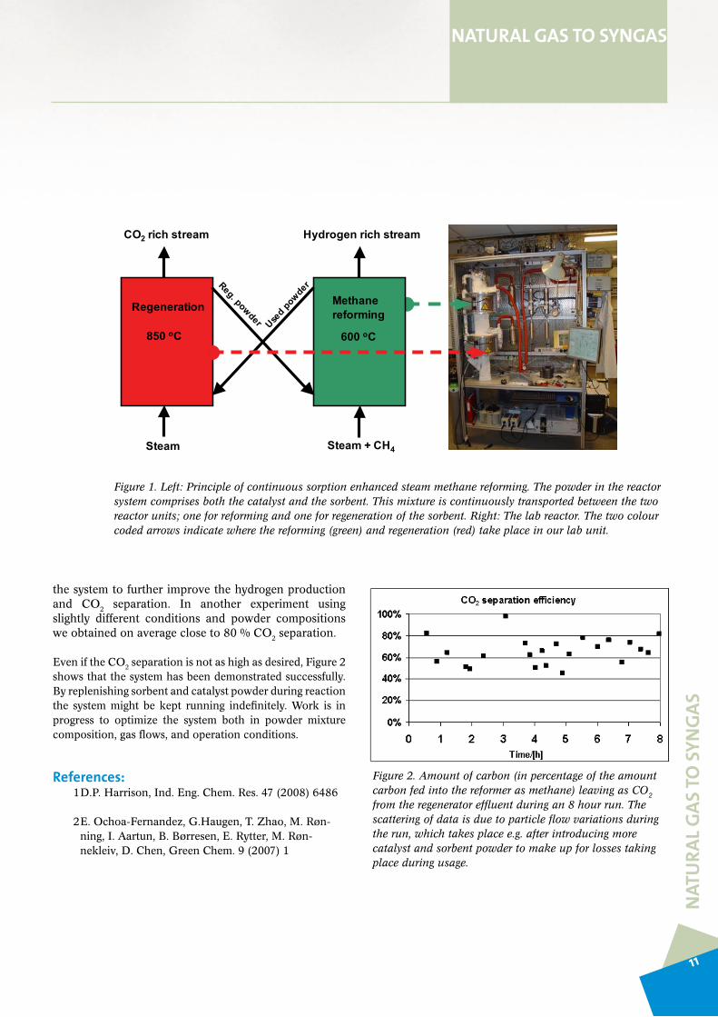
Figure 1. Left: Principle of continuous sorption enhanced steam methane reforming. The powder in the reactor system comprises both the catalyst and the sorbent. This mixture is continuously transported between the two reactor units; one for reforming and one for regeneration of the sorbent. Right: The lab reactor. The two colour coded arrows indicate where the reforming (green) and regeneration (red) take place in our lab unit.
the system to further improve the hydrogen production and CO2 separation. In another experiment using slightly different conditions and powder compositions weobtainedonaveragecloseto80%CO2 separation.
EveniftheCO2 separation is not as high as desired, Figure 2 shows that the system has been demonstrated successfully. By replenishing sorbent and catalyst powder during reaction the systemmightbekept running indefinitely.Work is inprogress to optimize the system both in powder mixture composition, gas flows, and operation conditions.
References:1D.P.Harrison,Ind.Eng.Chem.Res.47(2008)6486
2E.Ochoa-Fernandez,G.Haugen,T.Zhao,M.Røn-ning,I.Aartun,B.Børresen,E.Rytter,M.Røn-nekleiv,D.Chen,GreenChem.9(2007)1
NATURAL GAS TO SYNGAS
NAT
URA
L GAS
TO S
YNGA
S
Figure 2. Amount of carbon (in percentage of the amount carbon fed into the reformer as methane) leaving as CO2 from the regenerator effluent during an 8 hour run. The scattering of data is due to particle flow variations during the run, which takes place e.g. after introducing more catalyst and sorbent powder to make up for losses taking place during usage.
Used powderReg. powder
Hydrogen rich stream
Steam + CH4
850 oC 600 oC
Steam
Regeneration Methane reforming
CO2 rich stream
11

Study of deactivation mechanisms for Co-based Fischer-Tropsch catalysts
Approach and resultsThere are three main characteristics for making a catalyst commercially successful and those are activity, selectivity andstability.SinceFischer-Tropschsynthesis(FTS)countsslightly less than a century of industrial application it may be considered as a well studied reaction. However, thedeactivation resistance of the catalyst plays a key role in the success of FTS commercialization.
Catalystdeactivation is amajor challenge inFT synthesisbecause these catalysts are exposed to a number of various deactivation routes. Recent studies are proposing re-oxidation of active sites[1], polymeric surface carbon formation[2] and sintering[3] as possible causes of deactivation. Detailed characterization of used FT catalyst could reveal information about the deactivation phenomena. However, severalfactors are making the analysis of used FT catalysts difficult. The amount of wax, which is the main reaction product, is limiting the range of techniques that can be used. The high sensitivity of the active phase towards oxygen hampers the handling procedure. This leads to low reliability of the results that are obtained through a procedure involving sampling, dewaxing and characterization at inert conditions. Thus, recent catalyst deactivation research has turned the attention to advanced in-situ (operando) characterizationtechniques. Proper selection of techniques will allow monitoring of changes occurring inside the reactor during FTS and provide information that will assist in improved understanding of the deactivation phenomena. Catalystcharacterization at realistic working conditions is necessary to obtain reliable data about the deactivation processes which are taking place during the FT reaction.
The last year the objective has been to establish reliableprocedures for characterization of used catalyst. A procedure for separating the used catalyst from the silicon carbide diluent by magnetic means has been established. An inert atmosphere de-waxing procedure was established and is being optimized. Additionally, a wide range of characterization techniques have been applied in order to identify and deconvolute a wide range of deactivation mechanisms. The techniques areXRD (X-ray diffraction),XAS(X-rayAbsorptionSpectroscopy,XANES&EXAFS),Raman spectroscopy, TPx (Temperature programmedtechniques) andchemisorption.Techniques likeTEMandXPSwillbecoveredinotherinGAPsub-projects.
Fresh and used catalysts from our laboratory fixed-bed reactorandfromtheslurrypilotplantatStatoilHydrohavebeen characterized ex-situ in terms of particle size and degree of reduction. Suitable techniques for such measurements are HRXRDandXANES,respectively.Theresultsshowthatthechanges in the catalysts during reaction are small. Further analysis of the data obtained on these samples is in progress. A continued optimization of the dewaxing procedure and introduction of new characterisation techniques are planned.
NAT
URA
L GAS
TO F
UEL
SNATURAL GAS TO FUELS
12

In order to avoid unwanted modification of the used samples due to sampling or dewaxing procedure increased attention has been given to in-situ techniques. Achieving realistic FT conditions (200-400ºC,20bar, syngas)with simultaneousdata collection is challenging. We have designed andconstructedamodifiedClausentype[5]in-situ cell in order to combine the photon based techniques and FT reaction under realistic conditions. This cell was successfully tested at the end of the year on the BM01B station at SNBL (ESRF,Grenoble, Figure 1). A quartz capillary was used
NAT
URA
L GAS
TO F
UEL
S
NATURAL GAS TO FUELS
asamicroscalefixedbedreactor(l=60mm,d=1mm)where the FT process was simulated. The cell geometry allows combined simultaneous XRD, XAS and Raman data collection. XANES curves had shown that cobalt reduction isgoingthroughtheCo3O4 →CoO→Costeps(Figure3).The catalyst was reduced under ambient pressure at 450oCand subsequently subjected to a reaction environment of20 bar and 210oC for severalminutes (Figure 2). Furtherextention of the studies is planned for 2009.
Figure 1. Graphical representation of the in situ setup assembly in SNBL – station BM01B (ESRF). The station combines XAS (XANES, EXAFS), HRXRD & Raman measurements and the setup uses a mass flow controllered gas distributing system, an air blower for heating and a Mass Spectrometer for product detection. The reactor is a 1mm in diameter quartz capillary which allows plug flow.
13

In situ Raman spectroscopy was performed at the Raman lab atNTNU.Reductionofastandardcatalystwasperformedinacommercialinsitucell(Figure3)atambientpressure.Active modes corresponding to the Co3O4 phase were detected at the initial steps of reduction in the temperature range up to 220°C. Compared to the normal reductionprocedure (4 hours at 400-450 °C, undilutedH2) Ramanspectroscopy is able to confirm that cobalt oxide particles
NAT
URA
L GAS
TO F
UEL
SNATURAL GAS TO FUELS
Figure 2. In-situ XANES spectra starting from the reduction of the catalyst through the initial reaction period.
are in strong interaction with the support[4] and these data will be correlated to the reduction route established by XAS.
Several parameters have a pronounced influence on the FT catalyst deactivation. Thus, it is essential to involve several characterization techniques in order to distinguish the influence of external conditions and identify the individual deactivation routes.
14
NAT
URA
L GAS
TO F
UEL
S
NATURAL GAS TO FUELS
References1.E.Blekkanet.al.Catalysis,20(2007)13–32.
2.Moodleyetal.AppliedCatalysisAGeneral354(2009)102–110.pdf
3.M.J.Overettetal.Prepr.Pap.-Am.Chem.Soc.,Div.Petr.Chem.53(2008)126.
4.X.X.Gaoetal.CatalysisToday,131(2008)211–218.
5.J.D.Grunwaldt&B.S.ClausenTopicsinCatalysis,18(2002)37-43.
Figure 3. Raman scattering in-house set up.
15

NAT
URA
L GAS
TO F
UEL
SNATURAL GAS TO FUELS
Characterization methods for used Fisher-Tropsch catalysts
X-ray diffraction, approach and resultsFischer-Tropsch catalysts with their nanoscale active particles can experience changes during the life-time of the catalyst. X-ray diffraction on powder samples is a fast and powerful way to characterize crystalline materials. The stability of the active cobalt species can therefore be monitored by frequent investigation. Especially the evolution of the crystallite size of the metal catalyst over time may give an important indication of the changes occurring within the system.
However, the investigation iscomplicatedby the fact thatthe catalyst system is immersed in hydrocarbon wax and by the presence of the catalyst support. The wax is partially crystalline and exhibit reflections which can overlap with the peaks attributable to the cobalt species of the catalyst. In addition, very little of the actual catalyst system may be present within the wax matrix. As the cobalt metal accounts for a minor part of the catalyst system, it will be even more difficult to accurately observe its contribution to the diffraction pattern.
Two approaches have been explored to circumvent these challenges. The observation of the weak metal reflections can be improved by switching to high intensity X-ray sources like a synchrotron (Figure 1). This is not alwaysstraightforwardly possible. Alternatively, the concentration of the catalyst system exposed to the X-rays can be improved by removing as much of the wax matrix as possible. This has the additional benefit of reducing the perturbation of the powder diffraction pattern by the presence of large amounts ofwax.However,thewaxalsoplaysaroleofprotectingthenanometer sized metal particles which are easily oxidized by contact with air from the environment. It therefore needs to be established that the wax removal does not affect the state of the catalyst system adversely. This was done by comparing the crystallite sizes of non-treated and treated samples.
Two methods of wax removal were tested. The first is facile tocarryout.Itessentiallyconsistsofmeltingthecatalyst/wax mixture and decanting as much of the liquefied wax as possible after the heavier catalyst particles had agglomerated at the bottom of the vessel. The catalyst material will still be covered by significant amounts of wax after this treatment, but it is sufficiently concentrated for a successful collection of diffraction data (Figure 2). In addition, the continuedpresence of wax in and around the catalyst particles offers continued protection from the environment. More complete removal of the wax can be achieved by chemical means in dissolving the wax in a suitable organic solvent. In this way most or all of the wax can be removed. This will allow performing even more characterization of the material using techniques which do not tolerate the presence of any type of potentially volatile hydrocarbon, e.g. high resolution TEM. This way of wax removal requires more stringent reaction conditions, e.g. working in absolutely inert environments, andhandlingoftheresultantmaterial.Consequently,foraquick analysis of samples the first, physical method of wax removal is preferred, while the second, chemical method is utilized for samples that shall be investigated by a variety of techniques.
The analysis of samples treated in the various manners revealed crystallite sizes which corresponded very well with eachother(Table1).Asaresultallofthemethodsmentionedabove can be considered eligible for the treatment of wax covered Fischer-Tropsch catalysts, enabling the application of more profound methods of characterization.
16

NAT
URA
L GAS
TO F
UEL
S
NATURAL GAS TO FUELS
Figure 1. Comparison of X-ray diffraction data using conventional lab XRD equipment (left, 9 hours for the complete measurement), a synchrotron source and a high-resolution analyzer crystal detector system (center, approximately 15 minutes for the measurement) and a synchrotron source and an image plate based detector (right, ca. 2 minutes for the measurement).
Figure 2. Comparison of an as-received (orange) and de-waxed (blue) sample. The de-waxed sample shows much reduced intensity of the reflections due to wax, allowing analysis of the weak cobalt reflection which is overlapping with a reflection of the support (inset).
Sample treatment X-ray source Integral breadth crystallite size of the cobalt metal
As-received, filled into capillary by freeze-powdering
Synchrotron 1.8 nm
Physical wax removal Conventional 3.2 nmPhysical wax removal Synchrotron 2.4 nmChemical wax removal Synchrotron 1.9 nm
Table 1. Comparison of the results of the crystallite size analysis of a catalyst sample exposed to various types of pre-treatment.
17

NAT
URA
L GAS
TO F
UEL
SNATURAL GAS TO FUELS
TEM studies, approach and resultsTheTransmissionElectronMicroscope(TEM)isapowerfultool for the direct study of heterogeneous catalysts with a resolutiondown to the atomic scale. However, there aresignificant challenges in achieving the full potential of the technique. These include sample preparation and sample handling.
It is desirable to study the supported cobalt nanoparticles used in Fischer Tropsch catalysts in a state that is as close as possible to that in which the catalyst operates. One challenge is to observe the particles after reduction, as they oxidise rapidly on exposure to air. This can be achieved by transfer of the catalyst to the TEM from a glove-box. Based on experience gained by examining other types of air-sensitive material, this can be done either by using a dedicated sample transfer holder or using a standard sample holder that is transferred from the glove box to the TEM goniometer in an inert atmosphere.
FT reaction conditions cannot be achieved in the TEM. However,itispossibletoperformin-situ,dynamicstudiesin order to gain an insight into the behaviour of the catalyst particles when they are being exposed to different gases at elevated temperature and modest gas pressures. A working visithasbeenmadetotheCentreforElectronNanoscopy(CEN)atDTUinDenmark,whereanaberrationcorrectedenvironmental TEM is available, to study reduction processes in FT catalyst systems. This work was performed withThomasHansen andRafalDuninBorkowsky at theCEN.Thisisoneofthefewlaboratoriesintheworldwherethis kind of analysis can be performed.
Figure 1.Scanning transmission electron image showing a fresh catalyst that has been prepared as a thin section by ultramicrotomy. In the dark-field image, the catalyst nanoparticle aggregates show bright contrast relative to the support.
18

NAT
URA
L GAS
TO F
UEL
S
NATURAL GAS TO FUELS
Study of Fisher-Tropsch in micro-structured reactors
Approach and resultsMicrostructured reactor technology is an emerging technology for the Fischer-Tropsch synthesis (FTS).Commercial FTS in fixed-bed and slurry reactors benefitfrom large scale production. However, e.g. offshoreproduction would benefit from compact and modular conversion technology. Microstructured reactors have a large number of small, parallel channels with enhanced mass transfer properties and intensified heat transfer, enabling isothermal operation of the highly exothermic FTS reactions. To study its potential for FTS and to verify claims from technology providers, a microstructured reactor is fabricated at Forschnungszentrum Karlsruhe.
Figure 1. Microstructured reactor for Fischer-Tropsch synthesis
FTSwasperformedwith apowderCoRe/γ-Al2O3 catalyst inamicrostructuredreactor(Figure1)andcomparedwithresults obtained with the same catalyst in a lab-scale fixed-bed reactor under similar conditions.
Table 1 shows the results obtained in the microstructured reactor and the fixed-bed reactor. The results obtained with undiluted catalyst in the microstructured reactor are similar toresultswithdiluted(SiC)catalystinthefixedbedreactor.These are promising results, considering the modular scalability properties of microstructured reactors. In addition, the microstructured reactor has lower deactivation rate at higher temperatures and can be operated at severe conditions without temperature runaways in the catalyst.
Table 1. Productivity and selectivity from FTS in a fixed-bed reactor (FBR) and a microstructured reactor (MSR) with 20Co0.5Re5Ni/Al2O3.
(1) Relative deactivation rate at this time on stream, ( )trr
∆×∆
Reactor FBR MSR
Temperature (°C) 210 215 225 240 210 215 225 240Pressure (bar) 20 20 20 20 20 20 20 20GHSV (ml / g h) 10500 12300 14400 20500 12300 14400 14400 20500CO-conv (%) 47 48 59 80 47 51 72 83Sel C5+ (%) 83 83 84 81 84 83 84 82Sel CH4 (%) 8 9 9 12 9 9 9 12HC rate (g / g h) 1.0 1.2 2.0 3.3 1.1 1.5 2.1 3.4Rel. deact. rate(1)*(10-3)
1.5 0.9 5.4 10.0 12 1.0 2.9 4.5
TOS (h) 60 114 128 150 70 40 118 140
19

NAT
URA
L GAS
TO F
UEL
SNATURAL GAS TO FUELS
Slurry attrition testing of Fischer-Tropsch catalysts
Approach and resultsThe objective of the activity is to develop a method formeasuring strength, i.e. attrition resistance, of Fischer-Tropsch catalysts under realistic slurry conditions. Attrition resistance is a critical parameter for operation of modern slurry reactors. Some generation of fine material is inevitable under the turbulent environments in the reactor, and these fines may cause loss of catalyst material from the reactor, contamination of downstream upgrading steps, impurities in the products and clogging of separation systems. On the other hand, modern FT-catalysts are very strong and measuring attrition in the laboratory is challenging, Further
it is known that the FT-slurry environments include steam and small amounts of organic acids that likely will influence the mechanical and chemical integrity of the particles.
In 2008 experiments were performed first at room temperature with catalyst and oil, thereafter at ca. 20 bar and 220 oC.TheoilusedsimulatespropertiesofFT-liquidat the target temperature and pressure. A method was also developed for addition of steam through an internal evaporation device. Much effort was spent on developing a method for measuring attrited fines, and an optical transparency(haze)methodwasfoundsuitable.
Figure 1. Haze measurements of fines.
20

NAT
URA
L GAS
TO F
UEL
S
NATURAL GAS TO FUELS
The main conclusions are:•Theslurryreactorsystemoperatesasexpectedsimu-
lating FT-conditions. Particular care must be exer-cised when samples are withdrawn from the reactor not to destroy the particles due to pressure drop and expansion of trapped gas.
•Highstirringspeedisneeded.Evenat2000rpmtheattrition is limited and may not simulate an acceler-ated test of FT-reactor conditions.
•Itispossibletomeasurethefinesgeneratedbyusingahazeanalysiswithexcellentreproducibility.Chang-esinparticlesizedistribution(Malvern)cannotbeseen.
•Additionofsteamhastheapparenteffectofincreas-ing attrition rate.
It has been decided that higher attrition rates will be needed to come closer to an accelerated FT-slurry test with an attrition mechanism more close to large scale operation. The work will continue with an improved impeller design and novel Malvern particle size method.
In Figure 1 it is demonstrated that in the sample cuvette larger particles settle during the first 4-6 min. Thereafter stable values are obtained characteristic of fines < 1 µm. A comparatively weak (upper curves) and strong (lowercurves)catalystwasused.Thereproducibility isexcellent.Figure2showsthestablehaze(attrition)valueasafunctionoftimeintheslurryreactorforthestrongcatalyst.Upto96hwereusedintheexperiment.Certainlyagradualincreasein the fines content can be seen.
Figure 2. Stable haze (attrition) value.
21

NAT
URA
L GAS
TO F
UEL
SNATURAL GAS TO FUELS
Model compounds for metal-support catalysts made by Atomic Layer Deposition
Approach and resultsThe catalytic reaction takes place on the surface of the heterogeneous catalyst. Therefore several such catalysts are madeofnanoparticlesonan(inert)mesoporoussubstrate.For these, the surface/volume ratio is large, the surfacereactivity of nanoparticle is high, and the nanoparticles can be finely dispersed over the large surface of the porous support. Atomic layer deposition (ALD) is a versatiletechnique to deposit homogeneously thin layers or means to provide nanoparticles on different types of surfaces, even on mesoporous substrates. ALD is a gas phase deposition technique and the film is built layer by layer at the atomic scale, through gas-surface reactions that ensure conformal and uniform coatings, high dispersion and a precise control of the thickness and composition [1]. In this project, themain goal is to synthesise and study model materials for catalysis. The two main catalytic processes of interest are the ammonia synthesis and the Fischer-Tropsch process.
Approach and resultsFirst, catalysts for the ammonia synthesis will be elaborated and studied. The ammonia synthesis is the second largest chemical industrial process, yet an important research field in catalysis. A most interesting catalyst for this reaction is CoMo-oxide. Catalysts accelerate not only the forwardreaction, but also the reverse. In this sense, ammonia decomposition could be a key to a new fuel cell based on ammonia [2].Theobjectiveof this study is toelaborateacatalystbycoatingmesoporoussubstrateswithCoMo-oxidebythemeansofALD.Duringthefirstyearoftheproject,theprocessofALDgrowthofMolybdenum-oxide(MoO3)has been developed and controlled. As cobalt-oxide films havebeenobtainedbyALDatUiOpreviously,thenextstepconsistsinelaboratingCoMo-oxidethinfilmsbyALDandcontrollingtheentireCo-Mo-OsystemanddepositionsofstoichiometricCo-Mo-oxides.Thisstudyisinprocess.Then
Figure 1. Working mechanisms of the NH3 fed SOFC [2]
22

NAT
URA
L GAS
TO F
UEL
S
NATURAL GAS TO FUELS
nanoparticles of Co-Mo-oxide will be deposited by ALDon different mesoporous materials, reduced and activated to provide metallic Co-Mo catalyst. Finally, the catalyticproperties will be tested.
The second study consists of the elaboration of model materials for the Fischer-Tropsch process. The aim here is to study the catalytic properties of the catalysts as function of the diameter of the pores of the substrate. Disks with uniform pore size will be coated by ALD with an oxide. Depending on the thickness of the oxide-films, ALD will e.g. allow the tuning of pore diameter between 10 and 200 nm. Next,Co-oxidewillbedepositedalsobyALDandactivatedthroughH2 reduction.
References1.Meng Ni, Dennis Leung, Journal of Power sources 185(2008)233-240.
2.MikkoRitala,MarkkuLeskelä,in:H.SNalwa(Ed.),HandbookofThinFilmMaterials,Vol.1,AcademicPress,SanDiego,CA(2001)103-159.
Figure 2. Schematic representation of the process
23

NATURAL GAS TO PETROCHEMICALS
Methanol – To – Olefins; The MTO-RTA project
Partners and tasksThe MTO project focuses on key issues connected withmaterial determined properties of the acidic, microporous SAPO-34 catalyst. The tasks are divided between the three project partners who concentrate on issues according totheir particular field of expertise;
•TheUniversityofOslo(UiO):Advancedcharacterisa-tion of selected samples
•SINTEF:Catalystsynthesisandassociatedcharac-terisation
•INEOS:Hydrothermalageing,characterisationandtesting in MTO
Scientific objectivesThe goal is to understand the mechanisms responsible for deactivation of SAPO-34 catalyst as a means towards improvedcatalyticsystems.Theobjectivesare:
•Studyeffectofacidsitedensityanddistributiononstability.
•StudySi-mobilityunderhydrothermalandMTOconditions.
•Studyeffectofcrystalimperfectsonstability.
MethodologyDuringthefirstyearsoftheproject,themainemphasishasbeen synthesis of model materials with controlled amounts of silicon, while using different synthesis routes and types of templates. An aim has simultaneously been to achieve batchesofthedifferentmaterialswithjustminordifferencesin particle size and morphology. The structural properties of the materials have been investigated by X-ray diffraction, in the home laboratory, as well using advanced tools at Swiss Norwegian Beam Lines at ESRF, Grenoble. Studies
on activity under hydrothermal and MTO conditions have been investigated at INEOS, e.g. by means of TEOM.
ResultsSynthesis methods for SAPO-34 have been established that produce samples with controlled crystallite size and Si-content. The symmetry of the structures (triclinic,rhombohedral)hasbeendeterminedbyXRD.Forcertaintemplates and synthesis conditions (with andwithoutHFaddition to the reactant gel) deviations from the normalcrystalformsareobserved.Thedegreeofintergrowth(SAPO-18/SAPO-34)isanotherimportantmaterialparameter.Theintergrowths are manifested in the XRD patterns through particular Bragg reflections, typically accompanied by deviations from the normal gaussian peak shape including also broad features in the background. Detailed studies of these intergrowths have been done on the basis of high resolution synchrotron diffraction data, partly involving modelling by means of the DIFFAX program.
In 2008 robust methods for producing 29Si enriched SAPO-materials have been developed; one based on 29Si as starting reactant, another based on 29SiO2. Experiments have confirmed that the materials synthesized according to these procedures behave similarly to those prepared by traditional routes. The developed procedures will be used for a series of 29Si solid state NMR studies in 2009.
The correlation between acid site density and the activity in MTO has been investigated and the findings indicate that each Si generate one strong acid site up to about 8% Si.
A detailed description of some selected results from the projectisgivenseparately.
NAT
URA
L GAS
TO P
ETRO
CHEM
ICAL
S
24

In Situ Studies of the SAPO-34 MTO Catalyst
Themethanoltoolefin(MTO)conversionprocessproducessome of the most valuable chemical building blocks from acheapandpotentiallyrenewablestartingmaterial.Usingtechniques and equipment developed as part of the inGAP projectwehavedirectlyobservedthephysicalbehaviourofthe catalyst for the first time under real working conditions.
Using high power X-rays generated at the EuropeanSynchrotron Radiation facility (ESRF) we have collectedstructural data on the SAPO-34 silicoaluminophosphate framework catalyst in real time during the MTO process. The X-rays at the ESRF allow us to collect a full set of data approximately every 100 seconds (Figure 1) whilerunning the reaction in a capillary flow cell linked to a mass spectrometer analyzing the output gases. Raman spectra have been collected simultaneously with a similar acquisition time to the X-ray data.
Analysis of the crystallographic data from the MTO process shows that SAPO-34 undergoes a significant expansion inonedirection (thec-axisextendsbynearly3%overall)during the reaction. This can be linked to the production of ethene as observed in the mass spectrum, which peaks soon after the addition of methanol then falls off as the catalyst expands(Figure2).
Westudiedthedrivingforcefortheexpansionofthecatalystby mapping the electron density in the SAPO-34 cages using the difference Fourier technique. This shows us where chemical material which is not part of the framework model is to be found. The maps show clear evidence of organic material building in the cages during the MTO process (Figure3).
NATURAL GAS TO PETROCHEMICALS
Figure 1. A) 3-dimensional representation of the powder diffraction patterns during MTO reaction, showing the significant changes in intensity for some of the reflections. B) 2-dimensional plot showing a significant shift in the position of some reflections, reflecting the anisotropic expansion of the unit cell during reaction.
NAT
URA
L GAS
TO P
ETRO
CHEM
ICAL
S
25

Figure 2. Ethene production in mass spectrum vs time plotted alongside c-axis variation for SAPO-34 during the MTO process at 500°C
Figure 3. Images of the residual electron density in the SAPO-34 cage, determined from difference Fourier maps. From left to right: 440°C before reaction, 4 minutes into reaction and 20 minutes into reaction. Red spheres = oxygen, green = phosphorus, blue = aluminum. The white contours represent residual electron density.
NATURAL GAS TO PETROCHEMICALSN
ATU
RAL G
AS TO
PET
ROCH
EMIC
ALS
� ���
���
���������
���������
���������������
����
������
���
���
�
����������������
���!
�"��
�"�#
����
����
�$
������
��������
26

Figure 4. FWHM of the (101) peak of SAPO-34 plotted against time during the MTO process at 500°C.
By studying the widths of the X-ray diffraction peaks during the process we can assess the strain caused by the build up of intermediates and coke during the reaction. The curve observed for this is very similar to that for the structural expansion(Figure4).
ExperimentsinwhichthecatalystwassubjectedtorepeatedcyclesofMTOprocessingandcalcination(burningoutoftheorganicmaterialat550°C)showthatthecatalystcanbounce back to its original size after use and be ready for another cycle of MTO conversion. Experiments at higher temperature suggest though that complete recovery of the structure may be prevented under more extreme reaction conditions(Figure5).
The new data provide a significant and novel insight into the real processes going on in the MTO reaction and the stresses experienced by the catalyst.
NATURAL GAS TO PETROCHEMICALS
NAT
URA
L GAS
TO P
ETRO
CHEM
ICAL
S
� ��� ��� #��
�����
�����
����%
���"�
&'
(�
�����
������������
��)(������
�������
� ��� ��� #��
�"���
�"��"
�"�"�
���(������)(���)�*(�
���
����
�$
������������
�
���
���
#��
���
"��
+��
!��
�����������
����
����
���
��,
�����������������������������������������������������������������
����������������� !�"���#������������������������������� ��������$%� %��%��&'�(!)�
��������$�������������*����(�+,���-%��*��������������.%��������*�����*�����*�����%��
��������*��%�.������%��.������*��%�����.�����������.�����*��������*���%��*����
Figure 5.Plot of c-axis variation against time for a reaction in which the SAPO-34 catalyst was regenerated in O2/He. The different atmospheres used are denoted by the colour and shape of the plot and the temperature is plotted alongside the data.
27

NAT
URA
L GAS
TO P
ETRO
CHEM
ICAL
S
Model compounds – microporous
Scientific ProblemTo obtain inGAP’s vision, we need to obtain both new fundamentalinsightaboutthestructure/reactionmechanismrelationship and we need to be able to synthesize the next generation catalyst that we hopefully will be able to suggest on the basis of the mechanistic studies. This part of the projectfocusesonthesynthesisofSAPO-34typematerials(CHA-topologywithaluminumphosphatelatticeandwitha variable degree of Si substitution) There is a parallelprojectstudyingSSZ-13typematerials(CHA-topologywitha silicate lattice and with a variable degree of Al substitution anddistribution).
The challenge is to synthesize the material with a controlled continuous T-atom substitution and at the same time control the local environment around the hetero-atom.
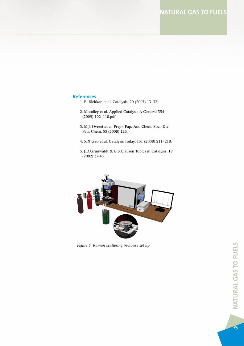
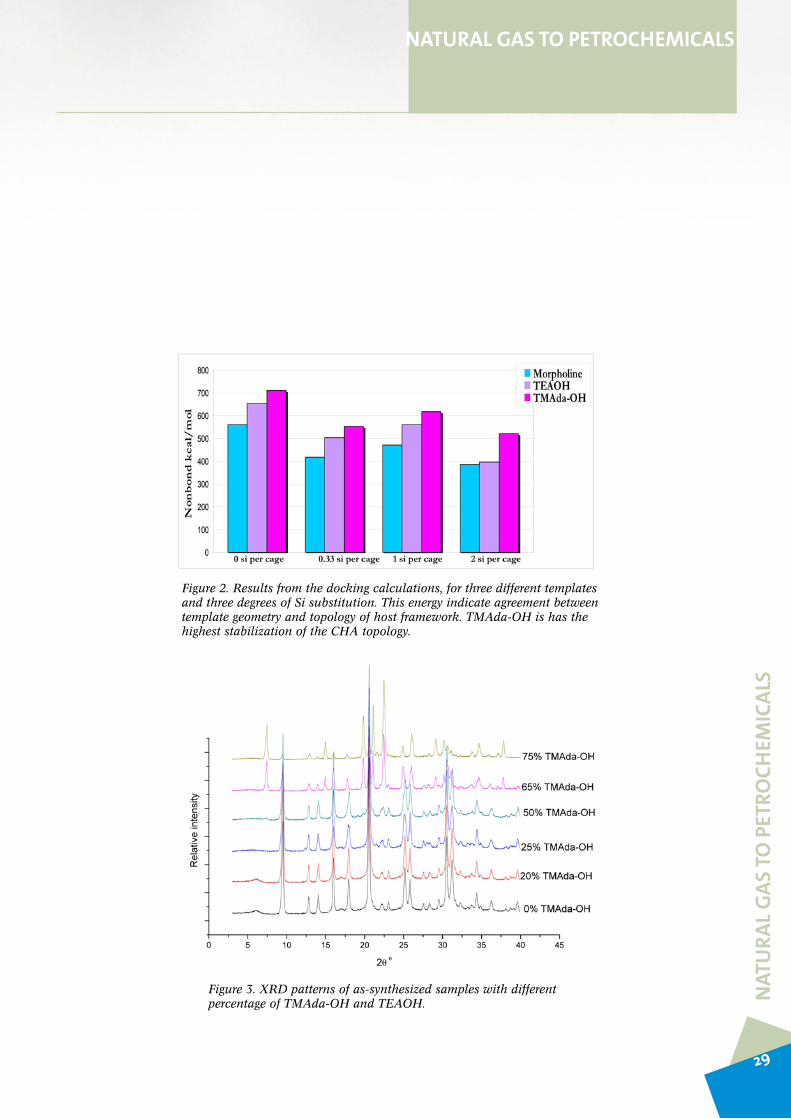
ApproachSeveral organic amines have been used as template for the synthesis of SAPO-34. Organic template plays an important role in the synthesis of molecular sieves, such as structure directing, space-filling and charge-compensation. The template will also affect elemental composition, local microscopic structure and morphology. The strongly structuredirectingtemplateTMAda-OHisforthefirsttimeused in SAPO-34 synthesis. The energy stabilization of the structurehasbeencalculated.TMAda-OHis the templatethat gives the highest stability for the of the SAPO-structure independentoftheamountofSisubstitution(Figure2).
TMAda-OHhasnotbeenusedbeforeastemplateforSAPO-34 synthesis. In this study SAPO-34 is synthesized using N,N,N trimethyl-1-adamantammonium as single template or in a mixture of it with tetraethyl ammonium hydroxide of(TEA-OH).Figure3presenttheresultsfromasystematicreplacement of the template. The goal is to synthesize phase pure SAPO-34 with a systematic variation in stability.
NATURAL GAS TO PETROCHEMICALS
Figure 1. SAPO-34 structure with TMAda-OH as template (left) and TEAOH (middle) and Morpholine (right) as template
28
NAT
URA
L GAS
TO P
ETRO
CHEM
ICAL
S
NATURAL GAS TO PETROCHEMICALS
Figure 2. Results from the docking calculations, for three different templates and three degrees of Si substitution. This energy indicate agreement between template geometry and topology of host framework. TMAda-OH is has the highest stabilization of the CHA topology.
Figure 3. XRD patterns of as-synthesized samples with different percentage of TMAda-OH and TEAOH.
29

NAT
URA
L GAS
TO P
ETRO
CHEM
ICAL
SNATURAL GAS TO PETROCHEMICALS
Part of this study is dedicated to preferred T-atom distribution in the CHA topology. The local distribution of Al atomsin silica based materials and the Si atoms in AlPO based materials are important for both catalytic properties stability. The main contribution of the differences in lattice energy is related to the electrostatic term. This can be simulated relatively fast with sufficient accuracy with molecular mechanics. Results from calculations on Si distribution in chabazitewith theGULP program is shown in Figure4. A significant stabilization of Al-pairs is observed for the situationwhere thecharge iscompensatedbyOHgroupson the oxygen connecting the Si-Al. Si substitution in AlPO materials is more complicated than Al-substitution, because Si-Sinextnearestneighboursareallowed.Computationallyfast methods are therefore needed in order to cover the large number of models and the large unit cells required. Selected low energy configurations will then be studied in more detail by quantum mechanical models.
Quantum mechanical calculations are needed to identify the most stable location of the protons in a cluster formed by a two Al-atom substitution in a four-ring. Figure 5 illustrates the most stable configuration.
Experimental determination of T-atom distribution is challenging. 29Si{1H} NMR has been demonstrated tobe a powerful tool for the mapping of Al-distribution in silica-based materials. This will be done in parallel to the theoretical studies. Most of this work will be done in parallel projects.
ReferencesVistad,OB;Akporiaye,DE;Lillerud,KP“Identifica-
tion of a key precursor phase for synthesis of SAPO-34 and kinetics of formation investigated by in situ X-ray diffraction”, J Phys. Chem. B 2001105(50):12437-
Vistad,OB;Akporiaye,DE;Taulelle,F;Lillerud,KP,”InSituNMRofSAPO-34Crystallization”,Chem. Mater. 2003, 15, 1639-1649
Vistad,OB;Akporiaye,DE;Taulelle,F;Lillerud,KP.”Morpholine,aninSitu13CNMRpHMeterforHydrothermalcrystallogenesisofSAPO-34“,Chem. Mater. 2003, 15, 1650-1654
Bordiga,S;Regli,L;Lamberti,C;Zecchina,A;Bjor-gen, Mn; Lillerud, KP. “FTIR Adsorption Studies ofH2OandCH3OHintheIsostructuralH-SSZ-13andH-SAPO-34:FormationofH-BondedAdductsandProtonatedClusters”.J. Phys. Chem. B 2005, 109(16),7724-7732.
Bordiga,S;Regli,L;Cocina,D;Lamberti,C;Bjorgen,M;Lillerud,KP.”AssessingtheAcidityofHighSilicaChabaziteH-SSZ-13byFTIRUsingCOasMolecularProbe:ComparisonwithH-SAPO-34”J. Phys. Chem. B 2005,109(7),2779-2784.
SchröderK.-P.;SauerJ.J.Phys.Chem.1993,97,6579-6581
Bordiga,S;Regli,L;Cocina,D;Lamberti,C;Bjorgen,M;Lillerud,KP.”AssessingtheAcidityofHighSilicaChabaziteH-SSZ-13byFTIRUsingCOasMolecularProbe:ComparisonwithH-SAPO-34”J. Phys. Chem. B 2005,109(7),2779-2784.
SchröderK.-P.;SauerJ.J.Phys.Chem.1993,97,6579-6581
30

NAT
URA
L GAS
TO P
ETRO
CHEM
ICAL
S
NATURAL GAS TO PETROCHEMICALS
Figure 4. Relative lattice energy as a function of the Al-Al distance in chabazite, calculated by the GULP program. The framework charge (-2 per hexagonal cell) is compensated (a) by protonation of O atoms or (b) by increasing all Si charges.
Figure 5. The structure on the left is calculated to be most stable structure and is about 102 KJ mole–1 more stable than the right one which is breaking Lowenstein’s rule.
31

NAT
URA
L GAS
TO P
ETRO
CHEM
ICAL
SNATURAL GAS TO PETROCHEMICALS
Acid strength influence on the MTO reaction over catalysts with CHA topology
Scientific challengeRational catalyst design requires detailed knowledge about the influence of individual parameters on reaction selectivity and mechanism. Single-parameter variation studies are rare in zeolite/zeotype catalysis, because of the difficultyto synthesize materials which at the same time meet the requirements of well-defined crystal shape, size, topology and density of acid sites. In the present study, our goal was to elucidate the role of acid strength alone on the Methanol-to-olefins(MTO)reaction,usingcatalystswithCHAtopology,i.e.;H-SAPO-34andH-SSZ-13.
ApproachH-SAPO-34andH-SSZ-13weresynthesisedwiththesamedensityofacidsites(Si/Al∼(Al+P)/Si∼ 12, i.e. one acid sitepercage)andcrystalsize(0.2-2microns).ThematerialswerecharacterizedbyXRD,SEM,IRspectroscopyandICPanalyses, and tested for activity, selectivity and stability for theMTOreaction300-425ºCandWHSV=6.0h−1.
The conversion of methanol versus time on stream over both catalystswas investigated at various temperatures (Figure1).H-SSZ-13possessesahigheractivityforreaction,witha shorter induction period and higher maximum conversion at the lower temperatures (Figure 1). Total methanolconversion capacities for the two catalysts are shown in Figure2.WhileH-SSZ-13hasahigherconversioncapacityat the lower temperatures, H-SAPO-34 has the highestoverall conversion capacity under the conditions tested, at 400ºC.
Theproduct spectrumof theCHA topology isdominatedby C2 andC3 hydrocarbonswith a smaller fraction of C4 hydrocarbons, and a very small amount of C5+ products. Figure4 shows theC2/C3 ratio as a function of methanol conversion (during deactivation) for both catalysts atthe various temperatures. The C2/C3 ratio increases with temperature over both catalysts. It is further observed thatalthoughtheinitialC2/C3 ratio is similar over the two catalysts for a given temperature, it increases rapidly, and the increase ismore abundant, overH-SSZ-13 comparedto H-SAPO-34. Analysis of retained hydrocarbons andcokeinthetwocatalystsaftervarioustimesonstream(notshown) showed thatH-SSZ-13containedmore cokeandaheavierhydrocarbonfractionthanH-SAPO-34underallconditions.
Inconclusion,H-SAPO-34andH-SSZ-13areverysimilarcatalysts for the methanol-to-olefins reaction. The results are consistent with a notion that the higher acid strength of H-SSZ-13 will lower the reaction barriers and thusincrease the rates of the reactions. The different evolution in product selectivity with time on stream suggests that the solid structures alone act very similarly as catalyst, but the differences in acid strength causes differences in the coke, which affect the product selectivity in the catalysts.
32

NAT
URA
L GAS
TO P
ETRO
CHEM
ICAL
S
NATURAL GAS TO PETROCHEMICALS
Figure 1. Conversion of methanol over H-SAPO-34 (left panel) and H-SSZ-13 (right panel) at various reaction temperatures and WHSV = 6.0 g g-1 h-1. The arrows indicate an increase in reaction temperature.
Figure 2 . Total amount of methanol converted by the time the catalyst was deactivated to 20% conversion in units of g methanol converted/g catalyst at various reaction temperatures.
����������������������������������������������������
���������������
�������������������������
���������������
0 60 120 180 240 3000
20
40
60
80
100
0 60 120 180 240 3000
20
40
60
80
100
Met
hano
l con
vers
ion
(%)
TOS (min)
H-SSZ-13 300°C 325°C 350°C 375°C 400°C
H-SAPO-34 300°C 325°C 350°C 375°C 400°C 425°C
Met
hano
l con
vers
ion
(%)
TOS (min)0 60 120 180 240 300
0
20
40
60
80
100
0 60 120 180 240 3000
20
40
60
80
100
Met
hano
l con
vers
ion
(%)
TOS (min)
H-SSZ-13 300°C 325°C 350°C 375°C 400°C
H-SAPO-34 300°C 325°C 350°C 375°C 400°C 425°C
Met
hano
l con
vers
ion
(%)
TOS (min)
33

NAT
URA
L GAS
TO P
ETRO
CHEM
ICAL
SNATURAL GAS TO PETROCHEMICALS
The results from this study have been published in:
F.Bleken,M.Bjørgen,L.Palumbo,S.Bordiga,S.Svelle,K.P.Lillerud,U.Olsbye The effect of acid strength on the conversion of methanol to olefins over acidic microporous catalysts with the CHA topologyTopicsinCatalysis52(3)(2009)218-228.
100 80 60 40 20 00.0
0.2
0.4
0.6
0.8
1.0
1.2
1.4
100 80 60 40 20 00.0
0.2
0.4
0.6
0.8
1.0
1.2
1.4Te
mpe
ratu
re
Efflu
ent C
2/C
3 ra
tio
MeOH conversion
300°C 325°C 350°C 375°C 400°C 425°C
H-SAPO-34
Efflu
ent C
2/C
3 ra
tio
MeOH conversion
H-SSZ-13
Tem
pera
ture
Figure 3. C2/C3 ratio in the effluent versus methanol conversion during life duration tests for the conversion of methanol over H-SAPO-34 (left panel) and H-SSZ-13 (right panel).
34

Olefin Technology
Scientific challengeThe reactions involved in the oxidative dehydrogenation of ethane are extremely fast and occur at a high temperature. Special challenges are thus connected to the mixing of reagents, heating, cooling and stabilization of reaction conditions, and there is therefore a need to develop special reactorsforthisapplication.ComputationalFluidDynamics(CFD)andheatandreactionmodelingofthesereactorsarenecessary to choose the best reactor and the best conditions for the process. A better understanding of the reaction kinetics for dehydrogenation of ethane, in the presence and absence of oxygen containing species, is important in optimizing the process conditions and the reactor model. Thehighreactiontemperatures(upto800-900°C)involvedleads to considerations regarding the choice of analytical method, sample and sample environment.
ApproachIn this study we have looked into the possibility of using in situinfraredemissionspectroscopy(IRES)tostudythehightemperature reactions involved in the gas phase reactions duringoxidativedehydrogenation/crackingofethane.
ResultsA literature study reveals that IRES only to a very limited extent has been used as an analytical technique for gas mixtures involving hydrocarbons. To our knowledge, small cells(closedsystems)havenotbeenreportedforstudiesofgases using IRES, and also no report on reaction kinetic studies has been found using such a method.
In the present study we have shown that a small, closed quartzcell(4mmI.D.)withacontinuousflowofgascanbeusedtoobservegasesinvolvedinoxidativedehydrogenation/cracking of ethane, like ethane, ethene, methane, CO2 andH2Oat high temperatures using IRES (Figure1). COcould just barely be detected in this cell, due to the lowtransparencyofquartzintheregionofCOstretch.
3200 3100 3000 2900 28001.0
1.2
1.4
1.6
1.8
2.0
2.2
Inte
nsity
Methane (CH4)
3200 3150 3100 3050 3000 2950 2900 2850 28001.00
1.25
1.50
1.75
2.00
Ethane (C2H
6)
Inte
nsity
3300 3200 3100 3000 2900 28001.0
1.1
1.2
1.3
1.4
1.5
1.6
Ethylene (C2H
4)
Inte
nsity
2500 2450 2400 2350 2300 2250 22001.00
1.05
1.10
1.15
Carbon dioxide (CO2)
Inte
nsity
2250 2220 2190 2160 2130 2100 20701.000
1.005
1.010
1.015
1.020
Carbon monoxide(CO)
Inte
nsity
4100 4000 3900 3800 3700 3600 3500 34001.00
1.05
1.10
1.15
1.20
1.25
1.30
Wavenumber(cm-1)
Water(H2O)
Inte
nsity
Wavenumber(cm-1)
Figure 1. In situ infrared emission spectra of methane, ethane, ethene, CO2, CO and H2O as measured in a 4 mm quartz cell at elevated temperatures
NAT
URA
L GAS
TO P
ETRO
CHEM
ICAL
S
NATURAL GAS TO PETROCHEMICALS
35

Figure 2. In situ infrared emission spectra of methane in argon at 500, 600 and 700°C, respectively. Right: The intensity of the band at 3018 cm-1 as a function of methane concentration.
IRES measurements of different concentrations of methane inargonattemperaturesbetween500and700°Cshowthatthere exist a linear relationship between the intensity of theC-Hstretchingvibrationatabout3018cm-1(withroto-vibrationalcontour)andthemethaneconcentration(Figure2).ThisimpliesthatIRESisasuitablein situ quantitative analytical technique for methane at high temperatures.
It has further been shown that the IRES method can be used as an in situquantitativeanalyticaltechniqueforCO2 at700°CafterreducingtheatmosphericCO2 content to an acceptable level.
However,thelackoftransparencyofthequartzcellbelow2150 cm-1 excludes the observation of spectroscopic features present in this region for different compounds. Promising results have been obtained by replacing the quartz cell with a BaF2 cell that allows us to extend the IR transparent region to 700 cm-1. The access to this region plays an important role in our study.
NAT
URA
L GAS
TO P
ETRO
CHEM
ICAL
SNATURAL GAS TO PETROCHEMICALS
36

Process intensification reactor
Scientific challengeMany processes concerning conversion of natural gas are highly endothermic or highly exothermic. Consequently,a large part of the cost for modern synthesis gas plants is related to heat exchangers rather than to the reactor itself. In a fluidized bed reactor the rate of heat transfer between gas and particles is high, as solids typically have a heat capacity that is several orders of magnitude higher than gases. This will prevent rapid temperature changes, and gives a large margin for safety in avoiding temperature runaways for highly exothermic reactions.
ApproachA compact, fluidized bed reactor, utilizing an efficient heat exchange between a highly endothermic and a highly exothermic reaction has been suggested. A feasibility study of the proposed reactor concept is being carried out through acombinedmodelling/experimentalapproach.
ResultsAn initial evaluation of the feasibility of the compact, fluidized bed reactor with respect to production capacity and energy transfer has been carried out. The critical question is regarded as to whether it is possible to construct such a reactor with high gas velocities and a sufficient amount of solids to make a sufficient heat exchange. By using a simplified reactor geometry, parameters like gas velocity, particle size and average particle volume fraction have systematicallybeenvariedbyCFDmodelling.Thereactorconcept is based on internal circulation and separation of the solids, and Figure 1 shows an example of how the particle density distribution is affected in a central part of thereactorataninletgasvelocityof28m/s,aparticlesizeof 500μm and a particle volume fraction of 15%.
Figure 1 Example of 2D CFD modelling of particle circulation in the compact, fluidized bed reactor after a) 0.1s, b) 0.3s, c) 0.5s and d) 2.0s.
a b c d
NAT
URA
L GAS
TO P
ETRO
CHEM
ICAL
S
NATURAL GAS TO PETROCHEMICALS
37

Vinyl chloride monomer (vcm)
INEOSChlorVinyls(previouslyHydroPolymers)operatesanumberof plantswhereVCM is produced frometheneandchlorine.TheVCMplantatRafnes,Norway, isbasedon ethene produced from ethane that is extracted from NaturalgasintheNorthSea.VCMispolymerizedtoPVC.VCM technology is amature technology but there is stillroom for process improvements, e.g., increased product yields, reduced by-product formation, catalyst stability, etc. Elementsofthisareaddressedinthisproject.
Scientific ProblemOxychlorination of ethene to EDC is one of the processsteps inabalancedVCMplant.Thecatalyticcycleof theoxychlorination process is shown in Scheme 1. As indicated in the Scheme, three distinct reaction steps take place: First cupper(II)chloride is reduced to cupper(I)chloridebyetheneformingthedesiredproductEDC,thenCu(I)isre-oxidisedoftoCu(II)byoxygen,andfinallythecatalyticcycle is completed by hydrochlorolysis of the oxychloride. Although the kinetics of the total oxychlorination reaction is known, the knowledge of the mechanisms and kinetics of each individual reaction step is still largely unknown. The overall objective of the VCM project is therefore tofill in the unknown mechanistic and kinetic gaps in the oxychlorination cycle and construct a microkinetic model of the surface reactions based on these findings. Such a model will provide valuable insight on how to run the oxychlorination process in an optimal way. Even small improvements in the selectivity, yield and reliability will have large economical benefits.
ApproachA preliminary microkinetic model will be constructed based on the literature values available. The kinetic constants for individual reaction steps will be obtained from pulse reactionsusingafixedbedreactor.Heatofadsorptionwillbe measured by micro-calorimetry or equivalent methods. Molecular modelling may be required for estimation of lacking parameters in the model. The effect of conventional promoters, K and Mg on the kinetic parameters will be studied. In parallel, the reaction mechanism will be studied by in situ XANES and FTIR. The micro-kinetic model will be revised according to the new insight gained by the mechanistic studies. From these studies, also the missing knowledge will be identified. Experimental ways to fill these gaps will be sought within the inGAP consortium. Of possible methods that can give further insight on the surface mechanisms involved are in situ techniques such as RAMAN or micro reactor studies using isotope labelled gases (SSITKA).Themodelwillbevalidatedagainstdataobtained in a steady state micro reactor. Our aim is to obtain a complete picture of the total process within the inGAP period.
ResultsUntilnowworkhasbeendonetoupdatetheprojectteamon the state-of-art on the oxychlorination process. A PhD student that will work with the micro-kinetic modelling was employedatNTNUinNovember2008andaPhDstudentthat will work with the reaction mechanism was employed atUiO inOctober2008.Hewill stayat theUniveristyofTorinoinProfessorCarloLamberti’sgroupduringthefirstpart of his PhD.
NAT
URA
L GAS
TO P
ETRO
CHEM
ICAL
SNATURAL GAS TO PETROCHEMICALS
38

NEW CHEMISTRY
Metal-organic framework compounds with potential catalytic applications
Porous crystals are strategic materials with industrial applications within petrochemistry, catalysis and selective separation1. Their unique property is based on the molecular scaleporouscharacter.However, aprincipal limitationofzeolites and similar oxide based materials are the relatively small size of the pores, typically in the range of medium sized molecules.MetalOrganicFrameworks(MOFs)providedabreakthrough in this respect, with their potentially unlimited pore sizes and surface areas2. MOFs are frameworks where organic compounds link inorganic metal atoms or nano-sized metal oxide clusters to form extended networks3. This mixed organic inorganic internal surface opens new possibilities for selective adsorption and functionalization not obtainable in oxide based microporous materials. MOFs have,however,onemajordisadvantage,theirweakthermal4 andchemicalstability.Wehavedevelopedanewzirconiumbased inorganic building brick that allows the synthesis of very high surface area MOFs with unprecedented stability5. ThehighstabilityisbasedonthecombinationofstrongZr-Obondsandtheabilityof the innerZr6-cluster to rearrange reversibly upon removal or addition of μ3-OH groups,without any changes in the connecting carboxylates.
MOFs made with linkers containing only one benzene ring or similar inert hydrocarbons form neutral compounds with very high surface area, but with weak interactions with
adsorbing molecules. It is considerably more challenging to synthesize MOFs with functionalized linkers. Recently we havemadeUiO-66andthemoreopenUiO-67,surfacearea1200 and 3000 m2/grespectively,withaminefunctionalizedinternal surface.
1. Davis, M. E. Ordered porous materials for emerging applications. Nature, 417,813–821(2002).
2Férey,G.,Mellot-Draznieks,C.,Serre,C.&Millange,F.CrystallizedFrameworkswithGiantPores:AreThere Limits to the Possible? Acc. Chem. Res., 38, 217-225(2005).
3Férey,G.Hybridporoussolids:past,present,future.Chem. Soc. Rev., 37,191-214(2008).
4Férey,G.BuildingUnitsDesignandScaleChemistry.J. Solid State Chem., 152,37-48(2000).
5.J.HafizovicCavka,S.Jakobsen,U.Olsbye,N.Guil-lou,C.Lamberti,S.Bordiga,K.P.LillerudANewZirconiumInorganicBuildingBrickFormingMetalOrganic Frameworks with Exceptional Stability J. Am. Chem. Soc. 130(42) 13850-13851(2008).
Figure 1 The Zr-MOF structure UiO-66, left neutral lattice, right functionalized with NH2 groups attached to the benzene ring.
NEW
CH
EMIS
TRY
39

MET
HO
DSMETHODS
The following methods and equipment had been, or was being, installed or developed, by inGAP by the end of 2008:
EquipmentOperando equipment at the Swiss-Norwegian beamline at the ESRF synchrothron in Grenoble(France).TheequipmentisusedintheFischer-TropschandMethanol-to-olefinsprojects,asreportedabove.
Mass spectrometeratUiO.Thisunitisusedfore.g.mechanisticstudiesoftheMethanol-to-olefins reaction, as reported above.
3D option for Transmission Electron Microscopy at SINTEF. This unit is used in the Fischer-Tropschproject.
Atomic Layer Deposition reactoratUiO.SuchequipmentisusedinthePh.D.project:“Modelcompounds–metal/support”.
MicrocalorimeteratNTNU.Theunitwasunderinstallationbytheendof2008.
Catalytic pre-treatment cell for XPS at SINTEF. The unit was under installation by the end of 2008.
In-situ cell for IR instrument at SINTEF. The unit was under installation by the end of 2008.
Sulfide adsorption instrument at UiO. The unit was under installation by the end of2008.
MethodsInfrared emission spectroscopyinOlefinsTechnologyproject
Attrition testing under simulated operating conditionsinFischer-Tropschproject
40

INTERNATIONAL COLLABORATION
INTERNATIONAL COLLABORATION
International collaboration in inGAP is based on the following elements:
International Scientific Advisory board The Advisors are both sources of scientific inspiration though plenary lectures at annual inGAP seminars, and collaboration partners, hostingPh.D.studentsfromtheCentre.In2008,aPh.D.studentfromaCentrepartnerstarteda6months researchperiodat theUniversityofUtrecht (TheNetherlands),andanotherPh.D.studentwillspend4monthsattheUniversityofBerkeley(US)in2009.
Sabbatical leavesProf.Karl-PetterLillerudspentoneyearattheUniversityofVersailles(France)in2007-2008.Assoc.Prof.HildeJ.VenvikspendsoneyearattheUniversityofWisconsin(US)in2008-2009.
Project collaboration In addition to the international collaboration partners mentioned above,theCentrehason-goingcollaborationswiththeUniversityofTurin(UNITO)(Italy),theSwiss-NorwegianBeamlines(SNBL)attheEuropeanSynchrothronRadiationFacility(ESRF)inGrenoble(France),theUniversityofCambridge(UK),theHumboldtUniversityinBerlin(Germany),CNRSLyon(France)andtheUniversityofCalifornia(USA).
OnePh.D.studentwithintheCentreispresentlyspendingoneyearattheUniversityofTurin (Italy) as apartofhisPh.D.AnotherPh.D. studentwithin theCentre spentonemonthattheCNRSLyon(France)during2008toreceivetraininginusingnewequipmentpurchased within inGAP.
41

RECRUITMENT
RECRUITMENT
inGAP has a goal of educating 18 Ph.D. students and 10-12 Postdoc fellows or researchers duringtheexpected8yearlifespanoftheCentre.Thattranslatesinto11Ph.D.sand6-8Postdocsduringthefirst5yearsofoperation(i.e.thesignedcontracttime).Bytheendof2008,8Ph.D.studentsand2PostdocfellowswereworkingintheCentre.3ofthePh.Dstudents are female, making the female share 38 %. Both Postdoc fellows employed this far aremale.However,4newPostdocfellowshavesignedcontractswithinGAPtobegintheirwork in 2009. By the end of 2009, the female share of Postdocs will thus reach 33%.
In total, inGAP is well on track compared to the goals of employment for the first five years.
COMMUNICATION
COMMUNICATION
Scientific communication from inGAP to the international scientific community is assured by oral and poster presentations at international conferences, as well as publications in the open literature.
inGAP has further created a web site (www.ingap.uio.no) This site works both as aninternal portal for all inGAP personnel and as a presentation of inGAP activities for the international scientific community.
42

SUPPLEMENTS
SUPPLEMENTS
Name Nationality Period Sex M/F Topic Partner
Nikolaos Tsakoumis
Greek 1/2-2008 to 31/1-2011 M Fischer-Tropsch Technology NTNU
Eleni Patanou French 3/3-2008 to 2/3-2012 F Microkinetics/microcalorimetry
NTNU
Alexey Voronov Russian 1/4-2008 to 31/3-2011 M Study of deactivation mechanisms
NTNU
Hassan Jamil Dar Pakistani 1/8-2008 to 31/10-2011 M Olefin technology NTNUMiroslav Surma 1/12-2008 to 30/3-2012 M VCM technology NTNUMahsa Zokaie Iranian 9/11-2007 to 8/11-2011 F Model compounds-
microporousUiO
Madeleleine Diskus
French 1/10-2007 to 30/9-2010 F Model compounds-M/support
UiO
Naresh Muddada Indian 23/10-2008 to 22/10-2012 M Oxychlorination UiO
PhDstudentswithfinancialsupportfromtheCentrebudget
Name Nationality Period Sex M/F Topic Partner
Murugan Balasundaram
Indian 1/08-2008 to 30/7-2010 M HTMR UiO
Rune E. Johnsen Danish 1/12-2008 to 30/11-2010 M In-situ@UiO UiO
PhDstudentswithfinancialsupportfromtheCentrebudget
43

Name Funding Nationality Sex M/F Institutution
Anastasia Virnovskaia VISTA Norwegian F UiOKai Chung Szeto NFR/Frinat Norwegian M UiOJasmina Hafizovic NFR/KOSK Norwegian F UiOFredrica Mudu NFR/Renergi Italian F UiOLinn Edda Sommer NFR/KOSK German F UiOChristoph Sprung NFR/Renergi German M UiOFrancesca Bleken NFR/Frinat Norwegian F UiOBjørn Christian Enger NFR/Renergi Norwegian M NTNUSara Eiras Boullosa NFR/Renergi Spanish F NTNUNina Hammer NTNU Norwegian F NTNUAstrid Lervik Mejdell NTNU/Gasstek Norwegian F NTNUSilje Fosse Håkonsen NFR/Kosk Norwegian F NTNUHilde Meland NFR/SUP Norwegian F NTNUHamidreza Bakhtiary NFR/Petrom Iranian M NTNUXuyen Kim Phan NFR/Renergi Vietnamese F NTNUAnh Hoang Dam NFR/Renergi Vietnamese M NTNULi He NFR/Climit Chinese F NTNUFatemeh Hayer NFR/Gassmak Iranian F NTNUFan Huang NFR/Gassmak Chinese M NTNUSaima Sultana Kazi NFR/Renergi bangladeshi F NTNUShreyas Rane NFR/Gassmak Indian M NTNUTayyaba Noor NFR/Kosk Pakistani F NTNUOana Mihai NFR/Kosk Romenian F NTNUIlya Gorelkin NFR/Gassmak Russian M NTNUNavaneethan Muthuswamy NFR/Nanomat Indian M NTNUPaul Radstake NFR/Gassmak Dutch M NTNUJia Yang NFR/Kosk Chinese F NTNUZarka Sarubova NFR/Kosk Czech F NTNU
Ph.D.studentsworkingoncentre-relatedprojectswithfinancialsupportfromothersources
44

Name Nationality Sex M/F Institution
Merete Hellner Nilsen Norwegian F UiOStig Rune Sellevåg Norwegian M UiO
David Wragg English M UiO
Tiejun Zhao Chinese M NTNU
Santhosh Kumar Matam Indian M NTNU
Anna Lind Finnish F NTNU
Estelle Vanhaecke French F NTNU
Hongmin Wang Chinese M NTNU
Espen Wangen Norwegian M NTNU
Postdoctoralresearchersworkingoncentre-relatedprojectswithfinancialsupportfromothersources
Name Nationality Sex M/F
Xin Dai Chinese FEinar Eilertsen Norwegian MOle Vaaland Saure Norwegian MShewangizaw Teketel Ethiopian MWegard Skistad Norwegian MElin Melina Visur Norwegian FMarius Westgård Erichsen Norwegian M
MasterdegreestudentsworkingonprojectsrelatedtotheCentre
45

Partner Name Main research area
INEOS ChlorVinyls Terje Fuglerud Catalyst testing and characterisationLola Irene Sanna Catalyst testing and characterisationSteinar Kvisle Catalyst testing and characterisationArne Grønvold Catalyst testing and characterisationSiri-Mette Olsen Catalyst testing and characterisationTone Kleivane Catalyst testing and characterisation
NTNU Hilde Venvik Catalyst testing and characterisationAnders Holmen Catalyst testing and characterisationMagnus Rønning Catalyst testing and characterisationDe Chen Catalyst testing and characterisationEdd Blekkan Catalyst testing and characterisation
SINTEF Anna Maria Lind Catalyst synthesisAnne Andersen Catalyst synthesisArild Andersen Catalyst testingArne Karlsson Catalytst testing and characterisationAud I. Spjelkavik Catalyst synthesisAud M. Bouzga Catalyst characterisationBjørnar Arstad Catalyst testing and characterisationBritt Sommer Catalyst CharacterizationDuncan Akporiaye Catalyst synthesis and characterisationEdvard Bergene Catalytst testing and characterisationElisabeth Tangstad Catalytst testing and characterisationHarald Laux Rector ConstructionIvar M. Dahl Catalyst CharacterizationJasmina Hafizovic Catalyst synthesis and characterisationJoachim M. Graff Catalyst CharacterizationJody Veenendaahl Rector ConstructionJohn C. Walmsley Catalyst characterisationJon Olav Grepstad Rector ConstructionJon Tschudi Catalst CharacterizationKari Anne Andrassen Catalytst testing and CharacterisationKnut A. Bø Reactor ConstructionKnut Thorshaug Catalytst testing and characterisationLars G.W. Tvedt Reactor ConstructionMarit S. Stange Catalyst CharacterizationOdd.A. Lindvåg Catalyst TestingPascal Dietzel Catalyst synthesis and characterisation
Senior personnel
46

Per Erik Vullum Catalyst CharacterizationPer H. Sæther Reactor ConstructionRichard Blom Catalytst testing and characterisationRune Myrstad Catalytst testing and characterisationSabita Sarkar Reactor ConstructionSandro U. Nanot Catalytst testing and characterisationSile Fosse Håkonsen Catalytst testing and characterisationSpyridon Diplas Catalyst characterisationStig Rune Ulla Reactor ConstructionThijs Peters Catalyst Testing/Reactor ConstructionTorbjørn Gervan Catalytst testing and characterisationØrnulv Vistad Catalyst synthesis and characterisation
StatoilHydro Erling Rytter Catalyst synthesis, testing and characterisationØyvind Borg Catalyst synthesis, testing and characterisationSigrid Eri Catalyst synthesis, testing and characterisationTorild H. Skagseth Catalyst synthesis, testing and characterisationMorten Rønnekleiv Gas conversion R&D managementPål Søraker Catalyst synthesis, testing and characterisationJens Bragdø Smith Gas conversion process research and materials R&DDaniel Käck Materials testing and characterisationJahn Arild Svendsen Gas conversion process researchKnut Ingvar Åsen Gas conversion process researchKjersti Wilhelmsen Gas conversion process researchAstrid Iversen Technical supportAlf Olav Larsen Technical supportJorun Zahl Albertsen Materials testing and characterisationElisabeth Slevolden Materials testing and characterisation
UiO Poul Norby Catalyst synthesis and characterisationHelmer Fjellvåg Catalyst synthesis and characterisationOla Nilsen Catalyst synthesis and characterisationKarl Petter Lillerud Catalyst synthesis and characterisationSharmala Aravinthan Catalyst testing and characterisationUnni Olsbye Catalyst testing and characterisationStian Svelle Catalyst testing and characterisationSøren Jakobsen AdministrationSigurd Brændeland AdministrationOle Swang Quantum-chemical modeling
Partner Name Main research area
47

Fina
l acc
ount
(200
8) -
Fina
ncin
g (k
NO
K)FINANCING
Item
U
iO a
ctiv
ity
num
ber
RCN
Gra
ntH
ost:
UiO
NTN
USI
NTE
FBo
real
isIn
eos
Chlo
rVin
yls
Stat
oilH
ydro
Tota
l pu
blic
fin
anci
ng
Tota
l fin
anci
ngPu
bl. F
in./
Tota
l fin.
Upp
er
limit
ESA
rule
s
Type
of p
artn
er
1200
02
PP
RLa
rge
Ent.
Larg
e En
t.La
rge
Ent.
1. N
G to
syng
as1.1
New
app
roac
h to
met
al
dust
ing
stud
ies
1200
02
938
49
4796
0,49
1,00
1.2
Circ
ulat
ing
fluid
bed
for
syng
as p
rod
1200
0310
7
75
0
857
857
1,00
1,00
1.3
HTM
R12
0004
18
5
77
018
595
50,
191,
00
2
. NG
to fu
els
2.1 F
isch
er-T
rops
ch Te
chno
logy
1200
0516
1
412
27
5057
333
230,
170,
65
2.2
Stud
y of
dea
ctiv
atio
n m
echa
nism
s12
0006
75
818
893
893
1,00
1,00
2.
3 M
odel
com
poun
ds-M
/su
ppor
t 12
0007
100
1091
11
9111
911,
001,
00
3. N
G to
pe
troc
hem
ical
s3.
1 MTO
tech
nolo
gy12
0008
265
200
10
02
465
1467
0,32
0,65
3.
2 O
lefin
tech
nolo
gy12
0009
1000
29
9
1200
1299
2499
0,52
0,65
3.
3 VCM
tech
nolo
gy12
0010
0
37
59
1
3762
80,
061,
00
3.4
Mod
el co
mpo
unds
-m
icro
poro
us12
0011
100
1091
11
9111
911,
001,
00
3.
5 H
ydro
ther
mal
-el
ectr
oche
mic
al sy
nthe
sis
1200
27
112
11
211
21,
001,
00
3.
6 Pr
oces
s int
ensi
ficat
ion
reac
tor
1200
28
340
34
034
0
3.
7 O
xych
lorin
atio
n
1618
2
198
198
1,00
1,00
4. N
ew ch
emis
try
4.1 C
once
pt e
valu
atio
n12
0030
30
0
300
300
1,00
1,00
5. M
etho
ds/
equi
pmen
t5.
1 In-
situ
@U
iO12
0012
810
0
108
108
1,00
1,00
5.
2 Tec
hn p
ositi
on a
t UiO
1200
13
520
52
052
01,
001,
00
5.3 T
heor
etic
al m
odel
ling
at U
iO12
0014
16
2
162
162
1,00
1,00
5.
4 M
icro
kine
tics/
mic
roca
lorim
etry
1200
1583
90
9
99
299
21,
001,
00
5.
5 In
situ
@sn
bl12
0016
207
75
282
282
1,00
1,00
5.
7 TEM
1200
1860
6060
1,00
1,00
5.
8 AL
CVD
1200
1951
15
6666
1,00
1,00
5.
9 M
S12
0022
105
105
105
1,00
1,00
5.
10 M
icro
calo
rimet
er12
0023
323
323
323
1,00
1,00
5.
11 D
RIFT
S eq
uipm
ent
1200
2440
0
40
040
01,
001,
00
5.12
Che
mis
orpt
ion
inst
rum
ent
1200
2518
2
18
218
21,
001,
00
6
. Adm
inis
trat
ion
6.1 A
dmin
istr
atio
n99
0000
2519
3711
6
26
7226
721,
001,
00
6.2 W
orks
hop
and
sem
inar
s90
0178
481
481
481
1,00
1,00
Tota
l bud
get
6243
3890
2704
1202
1200
1593
3569
1404
020
402
0,69
0,75
48

Fina
l acc
ount
200
8- C
ost
Item
U
iO a
ctiv
ity
num
ber
RCN
Gra
ntH
ost:
UiO
NTN
USI
NTE
FBo
real
isIn
eos
Chlo
rVin
yls
Stat
oilH
ydro
Tota
l pu
blic
fin
anci
ng
Tota
l fin
anci
ngPu
bl. F
in./
Tota
l fin.
Upp
er
limit
ESA
rule
s
Type
of p
artn
er
1200
02
PP
RLa
rge
Ent.
Larg
e En
t.La
rge
Ent.
1. N
G to
syng
as1.1
New
app
roac
h to
met
al
dust
ing
stud
ies
1200
02
938
49
4796
0,49
1,00
1.2
Circ
ulat
ing
fluid
bed
for
syng
as p
rod
1200
0310
7
75
0
857
857
1,00
1,00
1.3
HTM
R12
0004
18
5
77
018
595
50,
191,
00
2
. NG
to fu
els
2.1 F
isch
er-T
rops
ch Te
chno
logy
1200
0516
1
412
27
5057
333
230,
170,
65
2.2
Stud
y of
dea
ctiv
atio
n m
echa
nism
s12
0006
75
818
893
893
1,00
1,00
2.
3 M
odel
com
poun
ds-M
/su
ppor
t 12
0007
100
1091
11
9111
911,
001,
00
3. N
G to
pe
troc
hem
ical
s3.
1 MTO
tech
nolo
gy12
0008
265
200
10
02
465
1467
0,32
0,65
3.
2 O
lefin
tech
nolo
gy12
0009
1000
29
9
1200
1299
2499
0,52
0,65
3.
3 VCM
tech
nolo
gy12
0010
0
37
59
1
3762
80,
061,
00
3.4
Mod
el co
mpo
unds
-m
icro
poro
us12
0011
100
1091
11
9111
911,
001,
00
3.
5 H
ydro
ther
mal
-el
ectr
oche
mic
al sy
nthe
sis
1200
27
112
11
211
21,
001,
00
3.
6 Pr
oces
s int
ensi
ficat
ion
reac
tor
1200
28
340
34
034
0
3.
7 O
xych
lorin
atio
n
1618
2
198
198
1,00
1,00
4. N
ew ch
emis
try
4.1 C
once
pt e
valu
atio
n12
0030
30
0
300
300
1,00
1,00
5. M
etho
ds/
equi
pmen
t5.
1 In-
situ
@U
iO12
0012
810
0
108
108
1,00
1,00
5.
2 Tec
hn p
ositi
on a
t UiO
1200
13
520
52
052
01,
001,
00
5.3 T
heor
etic
al m
odel
ling
at U
iO12
0014
16
2
162
162
1,00
1,00
5.
4 M
icro
kine
tics/
mic
roca
lorim
etry
1200
1583
90
9
99
299
21,
001,
00
5.
5 In
situ
@sn
bl12
0016
207
75
282
282
1,00
1,00
5.
7 TEM
1200
1860
6060
1,00
1,00
5.
8 AL
CVD
1200
1951
15
6666
1,00
1,00
5.
9 M
S12
0022
105
105
105
1,00
1,00
5.
10 M
icro
calo
rimet
er12
0023
323
323
323
1,00
1,00
5.
11 D
RIFT
S eq
uipm
ent
1200
2440
0
40
040
01,
001,
00
5.12
Che
mis
orpt
ion
inst
rum
ent
1200
2518
2
18
218
21,
001,
00
6
. Adm
inis
trat
ion
6.1 A
dmin
istr
atio
n99
0000
2519
3711
6
26
7226
721,
001,
00
6.2 W
orks
hop
and
sem
inar
s90
0178
481
481
481
1,00
1,00
Tota
l bud
get
6243
3890
2704
1202
1200
1593
3569
1404
020
402
0,69
0,75
The
mat
ic -a
rea/
activ
ity
UiO
act
ivity
nu
mbe
rH
ost:
UiO
NTN
USI
NTE
FBo
real
isIn
eos
Chlo
rVin
yls
Stat
oilH
ydro
Tota
l
1. N
G to
syng
as1.1
New
app
roac
h to
met
al
dust
ing
stud
ies
1200
02
948
39
96
1.2
Circ
ulat
ing
fluid
bed
for
syng
as p
rod
1200
03
857
85
7
1.3
HTM
R12
0004
54
14
200
210
955
2
. NG
to fu
els
2.1 F
isch
er-T
rops
ch Te
chno
logy
1200
05
10
9171
5
15
1733
23
2.2
Stud
y of
dea
ctiv
atio
n m
echa
nism
s12
0006
893
893
2.
3 M
odel
com
poun
ds-M
/su
ppor
t 12
0007
11
91
1191
3
. NG
to
petr
oche
mic
als
3.1 M
TO te
chno
logy
1200
08
271
36
7
829
14
67
3.
2 O
lefin
tech
nolo
gy12
0009
33
794
1672
24
99
3.3 V
CM te
chno
logy
1200
10
14
034
45
4
628
3.
4 M
odel
com
poun
ds-
mic
ropo
rous
1200
11
1191
11
91
3.
5 H
ydro
ther
mal
-el
ectr
oche
mic
al sy
nthe
sis
1200
27
112
11
2
3.
6 Pr
oces
s int
ensi
ficat
ion
reac
tor
1200
28
340
34
0
3.
7 O
xych
lorin
atio
n
19
8
198
4
. New
ch
emis
try
4.1 C
once
pt e
valu
atio
n12
0030
30
0
300
5
. Met
hods
/eq
uipm
ent
5.1 I
n-si
tu@
UiO
1200
12
108
10
8
5.
2 Tec
hn p
ositi
on a
t UiO
1200
13
520
52
0
5.3 T
heor
etic
al m
odel
ling
at
UiO
1200
14
162
16
2
5.
4 M
icro
kine
tics/
mic
roca
lorim
etry
1200
15
99
2
99
2
5.
5. In
situ
@sn
bl12
0016
14
713
5
28
2
5.7 T
EM12
0018
60
60
5.
8 AL
CVD
1200
19
66
66
5.9
MS
1200
22
105
10
5
5.10
Mic
roca
lorim
eter
1200
23
32
3
32
3
5.11
DRI
FTS
equi
pmen
t12
0024
40
0
400
5.
12 C
hem
isor
ptio
n in
stru
men
t12
0025
18
2
182
6
. Ad
min
istr
atio
n6.
1 Adm
inis
trat
ion
9900
00
2299
197
176
26
72
6.
2 Wor
ksho
p an
d se
min
ars
9001
78
345
136
481
To
tal b
udge
t
7667
4753
4933
012
8317
6620
402
49
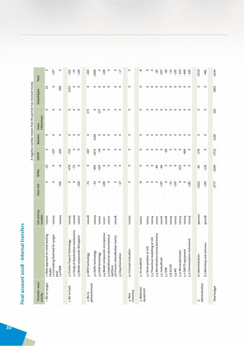
Fina
l acc
ount
200
8 - I
nter
nal t
rans
fers
A ne
gativ
e nu
mbe
r mea
ns th
at th
e pa
rtne
r has
reci
eved
mon
ey
The
mat
ic -a
rea/
activ
ity
UiO
act
ivity
nu
mbe
rH
ost:
UiO
NTN
USI
NTE
FBo
real
isIn
eos
Chlo
rVin
yls
Stat
oilH
ydro
Tota
l
1. N
G to
syng
as1.1
New
app
roac
h to
met
al d
ustin
g st
udie
s12
0002
0-1
00
00
100
1.2
Circ
ulat
ing
fluid
bed
for s
ynga
s pr
od12
0003
00
-107
00
0-1
07
1.3
HTM
R12
0004
-356
-4-2
000
056
00
2. N
G to
fuel
s2.
1 Fis
cher
-Tro
psch
Tech
nolo
gy12
0005
0-6
79-7
150
012
33-1
61
2.2
Stud
y of
dea
ctiv
atio
n m
echa
nism
s12
0006
0-7
50
00
0-7
5
2.3
Mod
el co
mpo
unds
-M/s
uppo
rt
1200
07-1
000
00
00
-100
3. N
G to
pe
troc
hem
ical
s3.
1 MTO
tech
nolo
gy12
0008
-71
0-3
670
173
0-2
65
3.
2 O
lefin
tech
nolo
gy12
0009
-33
-495
-167
212
000
0-1
000
3.
3 VCM
tech
nolo
gy12
0010
0-1
03-3
40
137
00
3.
4 M
odel
com
poun
ds-m
icro
poro
us12
0011
-100
00
00
0-1
00
3.5
Hyd
roth
erm
al-e
lect
roch
emic
al
synt
hesi
s12
0027
00
00
00
0
3.
6 Pr
oces
s int
ensi
ficat
ion
reac
tor
1200
280
00
00
00
3.
7 O
xych
lorin
atio
n
-17
00
00
0-1
7
4
. New
ch
emis
try
4.1 C
once
pt e
valu
atio
n12
0030
00
00
00
0
5. M
etho
ds/
equi
pmen
t5.
1 In-
situ
@U
iO12
0012
-80
00
00
-8
5.
2 Tec
hn p
ositi
on a
t UiO
1200
130
00
00
00
5.
3 The
oret
ical
mod
ellin
g at
UiO
1200
140
00
00
00
5.
4 M
icro
kine
tics/
mic
roca
lorim
etry
1200
150
-83
00
00
-83
5.
5. In
situ
@sn
bl12
0016
-147
-60
00
00
-207
5.
7 TEM
1200
180
0-6
00
00
-60
5.
8 AL
CVD
1200
19-5
10
00
00
-51
5.
9 M
S12
0022
-105
00
00
0-1
05
5.10
Mic
roca
lorim
eter
1200
230
-323
00
00
-323
5.
11 D
RIFT
S eq
uipm
ent
1200
240
0-4
000
00
-400
5.
12 C
hem
isor
ptio
n in
stru
men
t12
0025
-182
00
00
0-1
82
6
. Ad
min
istr
atio
n6.
1 Adm
inis
trat
ion
9900
00-2
262
-81
-176
00
0-2
519
6.
2 Wor
ksho
p an
d se
min
ars
9001
78-3
45-1
360
00
0-4
81
To
tal b
udge
t
-3
777
-204
9-3
731
1200
310
1803
-624
4
50

PUBLICATIONSInvited lectures at international conferences:
U.OlsbyeConversion of methanol to hydrocarbons over acidic zeolite and zeotype catalysts: Mechanistic insight as a first step towards ra-tional designKeynote lecture13thNordicSymposiumonCatalysisGøteborg,October5-7,2008
Presentations at international conferences:
Arstad,Bjørnar;Blom,Richard;Bakken,Egil;Dahl, Ivar; Jakob-sen, Jana; Røkke, Petter.Sorption-Enhanced methane steam reforming in a circulating fluidized bed reactor system. Poster presentationGHGT-9,WashingtonDC16-20November2008,Poster
Arstad,Bjørnar;Blom,Richard;Bakken,Egil;Dahl, Ivar; Jakob-sen, Jana; Røkke, Petter.Sorption-Enhanced methane steam reforming in a circulating fluidized bed reactor system. Energy Procedia(2008)Submitted,Proceding
Popular science lectures:
U.OlsbyeKatalyse gir mer for pengeneForskningens festaftenOslo, September 23, 2008
Publications by inGAP:
HafizovicCavka,Jasmina;Jakobsen,Soren;Olsbye,Unni;Guillou,Nathalie;Lamberti,Carlo;Bordiga,Silvia;Lillerud,KarlPetter. A New Zirconium Inorganic Building Brick Forming Metal Organic Frameworks with Exceptional Stability. Journal of theAmericanChemicalSociety (2008), 130(42), 13850-13851.
Arslan,Ilke,Walmsley,JohnC;Rytter,Erling;Bergene,EdvardaneMidgley, Paul A Toward three-dimensional nanoengineering of heterogeneous catalysts.JournaloftheAmericanChemicalSo-ciety(2008),130(17),5716-5719.
Book chapters by inGAP:
Kvisle,Steinar.Fuglerud,Terje.Kolboe,Stein.Olsbye,Unni,Lillerud,
Karl-Petter,Vora,Bipin.Methanol-To-Olefins.HandbookofHet-erogeneousCatalysis 2ed,Vol 8 2950-2965, EdGerhardErtl,Helmut Knøzinger, Ferdi Schuth and Jens Weitkamp. Wiley-VCHVerlagGbH&Co,2008
Popular science lectures from inGAP associated projects:
K. Thorshaug, S. Svelle, Katalysesymposiet 2007: Fokus på zeolit-ter,Kjemi,2(2008)22-23
Presentations on international conferences from inGAP associated projects:
B.C.Enger,R.Lødeng,A.Holmen:Modified nickel catalysts in the partial oxidation of methane at moderate temperatures. Poster. 13^th Nordic Symposium on Catalysis, 5-7 October,Gøteborg,Sweden.
B.C.Enger,R.Lødeng,A.Holmen:Nickel and nickel-cobalt spi-nel catalysts in the partial oxidation and steam reforming of methane, Oral presentation. 235^th ACS National Meeting,April6-102008,NewOrleans,LA,USA.
B.C.Enger,R.Lødeng,A.Holmen:Methane activation and syngas formation on low-loading Ni catalysts. Poster. 14. International CongressonCatalysis.July13-18,2008,COEX,Seoul,Korea.
Borg, Øyvind; Dietzel, Pascal D. C.; Spjelkavik, Aud I.; Tveten,ErikZ.;Walmsley, JohnC.;Eri, Sigrid;Holmen,Anders;Ryt-ter, Erling. Fischer-Tropsch synthesis: Effect of Co particle size and support on product distribution. Poster presentation, 14th InternationalCongressonCatalysis,Seoul,SouthKorea,13-18July 2008.
DeChen,Activities in NTNU network of carbon nanomaterials, oral presentation, Seminar on network of carbon nanomaterials, NFR, Oslo, 28 Aug. 2008.
De Chen, Multifunctional materials for hydrogen production from multifuels,oralpresentation,NorwegianHydrogensemi-nar, Bergen, 26-28, 2008
PUBLICATIONS
51
DeChen,Engineering of metal nanoparticles on carbon nano-fibers, Invited lecture, 3rd. International symposium on carbon for catalysis, Berlin, 9-12, Nov. 2008.
EddA.Blekkan,ØyvindBorg,VidarFrøseth,AndersHolmen. The effects of water on supported cobalt catalysts in the Fischer-Tropsch synthesis.14thInt.CongressonCatalysis,Seoul,KoreaJuly 13-18 2008.
Edd A. Blekkan. Fischer-Tropsch synthesis. GTS Lunch seminar June 17 2008.
Edd A. Blekkan. Norwegian downstream technology - education, research and industrial development. Gassmaks-seminar on “New business opportunities in a changing gas market”
Trondheim–TjeldbergoddenSep.23-242008.
Edd A. Blekkan. Chemistry of heavy oil upgrading.VISTA-semi-nar,StatoilHydroResearchCentre,TrondheimOct.14,2008.
Edd A. Blekkan. Biofuels.MiT-NTNUseminar,MiT,BostonOct.28-29, 2008.
EspenStandalWangen,AnneHoff,EddAndersBlekkan.Upgrad-ing of vacuum residue from Athabasca bitumen. 13th Nordic SymposiumonCatalysis,Gothenburg,SwedenOct.5-72008.
EstelleVanhaecke,FanHuang,DeChen,MagnusRønning,Syn-thesis and optimization of carbon nanostructures on foils. Poster, 3rd. International symposium on carbon for catalysis, Berlin, 9-12, Nov. 2008.
FanHuang,EstelleVanhaecke,DeChen,Synthesis of a conduc-tive polymer - CNT/CNF composites. Poster, 3rd. International symposium on carbon for catalysis, Berlin, 9-12, Nov. 2008.
H.Bakhtiary,F.Hayer,H.J.Venvik,A.Holmen:Kinetics and reac-tor modelling of methanol synthesis from synthesis gas in the fixed-bed reactor.Poster.13^thNordicSymposiumonCataly-sis,5-7October,Gøteborg,Sweden
HildeDyrbeck,KristianØstli,EddA.Blekkan.Selective hydrogen combustion in the presence of hydrocarbons:Catalysts sup-ported on hydrotalcite-like materials. 14th Int. Congress onCatalysis,Seoul,KoreaJuly13-182008.
IngvarKvande,MagnusRønning,DeChen,Structure-Properties - Performance Relationship of Carbon Nanofiber Supported Pt Catalysts, Carbon 228, ProceedingofCarbon2008,Nagano,Japan, 13-18 July, 2008.
Ingvar Kvande, Stein Trygve Briskeby, Tie-Jun Zhao, MikhailTsypkin, Inger Marie Skoe, John C. Walmsley, Magnus Røn-ning,Reidar Tunold, Svein Sunde,DeChen, Investigation of the adsorption strength of O and CO on Pt/CNF catalysts by a kinetic study of the hydrogen oxidation reaction, oral pre-sentation, International Symposium onCreation andControlofAdvancedSelectiveCatalysis,Kyoto,Japan,8-12July,2008.Abstract book.
IngvarKvande,JiaYang,SteinTrygveBriskeby,MagnusRønning,AndersHolmen,DeChenJohnC.Walmsle,SveinSunde,CO adsorption and desorption behaviour of carbon nanofiber sup-ported platinum catalysts, Oral presentation, 3rd. International symposium on carbon for catalysis, Berlin, 9-12, Nov. 2008.
J.P.denBreejen,P.B.Radstake,G.L.Bezemer,V.Frøseth,A.Hol-men,J.H.Bitter,K.P.deJong:Cobalto n carbon nanofibers as model catalyst: On the origin of the cobalt particle size effect in Fischer-Tropsch synthesis.Lecture.CarboCatIII,November9–122008,Berlin,Germany
JunZhu, JinghongZhou, TiejunZhao, Xinggui Zhou,DeChen,WeikangYuan.A novel heterogeneous catalyst for Heck reac-tion—Study of the metal-support interaction in Pd/CNF cata-lysts. Poster, The 20th International SymposiumonChemicalReaction Engineering, Kyoto, 7-10 Sep. 2008.
Jun Zhu, Tiejun Zhao, Ingvar Kvande, ChenDe, Xinggui Zhou,WeikangYuan,Catalysis with various morphology of palldium nanoparticles on carbon nanofiber: Nanoparticle shape de-pendence and stability, oral presentation, International Sympo-siumonnanocatalysis,DalianChina,13-18July,2008.
LiHe,MortenBeinset,HeleneBerntsen,TiejunZhao,DeChen,Multifunctional reactor for hydrogen production from multi-fuels, Keynote lecture, 12th Asia Pacific confederation of chemi-calengineeringcongress,Dalian,China,4-6Aug.2008.
LuWenxin,SuiZhijun,ZhouJinghong,LiPing,ZhouXingguiandDe Chen, Effect of hydrogen on the Synthesis of Carbon Nanofibers by CO Disproportionation on Ultra-Fine Fe3O4, Vol. 3, 265, Proceeding of 12th Asia Pacific confederation ofchemicalengineeringcongress,Dalian,China,4-6Aug.2008.
MagnusRønning,Combining results from XAS, Raman, STEM and TEOM to obtain reliable information about propane de-hydrogenation catalysts.
Swiss-Norwegian workshop on Simultaneous Raman-X-ray dif-fraction/absorption studies for the in situ investigations, Grenoble, June 18-19, 2008.
Magnus Rønning, Nanomaterials in Catalysis -Activities at NTNU.
Nanotechnology Workshop; UC Berkeley-StatoilHydro-NTNU,Rotvoll, Trondheim, Sep. 1 2008.
M.Lualdi,S.Løgdberg,S.Nassos,S.Järås,A.Holmen:Direct use of H_2 poor syngas in the Fischer-Tropsch synthesis. Poster. 13^thNordicSymposiumonCatalysis,5-7October,Gøteborg,Sweden.
MargreteHånesWesenberg.Konvertering av naturgass. Oral Pre-sentation,PetroleumsdagenUiO,Oslo,8February2008.
NinaHammer,MarcoSchubert,DeChen,MagnusRønning,Car-bon-carbon composite material as a catalytic reactor, Car-bon 89, ProceedingofCarbon2008,Nagano,Japan,13-18July,2008.
NinaHammer,MarcoSchubert,DeChen,MagnusRønning,Car-bon-carbon composite material as a catalytic reactor, Invited lecture,Carbon2008,Nagano,Japan,13-18July,2008.
PingLi,Yi-LiHuang,DeChen,Xing-GuiZhou,Tie-JunZhao,Wei-KangYuan,Hydrogen evolution from decalin over pre-cious metal catalysts supported on carbon nanofibers, oral presentation,Carbon2008,Nagano,Japan,13-18July,2008.
Poul Norby. In situ synchrotron powder X-ray diffraction stud-ies of catalytic materials.InvitedtalkattheIUCr2008meet-ing,(XXICongressandGeneralAssemblyoftheInternationalUnionofCrystallography).Osaka,Japan,23-31August2008
52

R.Lødeng,E.Bjørgum,B.C.Enger,A.Holmen;B.Krogh,B.T.Bør-resen, E. Rytter: Oxidative catalyric conversion of CH_4 to H_2 at low temperatures.Poster.14^THInternationalCongressonCatalysis.July13-18,2008,COEX,Seoul,Korea.
Rønning, Magnus Nanostructured materials in environmental catalysis. Invited speaker, 1stNanotechnology@NTNU; KavliSeminar.Sep-11-12,2008NTNU.
Rytter,Erling;Borg,Øyvind;Eri,Sigrid;Skagseth,TorildH.Signifi-cance of the Olefin to Paraffin Ratio in Cobalt Based Fischer-Tropsch Catalysis.OralPresentation,CATSA2008,KhayaIb-hubesi, South Africa, 9-12 November 2008.
SaraLøgdberg,ØyvindBorg,SvenJärås,EddA.Blekkan,AndersHolmen.Activity response upon external water addition to a narrow-pore CoRe/ γ-Al2O3 Fischer-Tropsch catalyst.14th Int. CongressonCatalysis,Seoul,KoreaJuly13-182008.
SarkaZarubova,Signe JohannaSexe,DeChen,SimonBallance,JanErikMichels,BjørnE.Christensen,MagnusRønning,The application of carbon nanofiber – carbon felt composite in bioseparation. Poster, 3rd. International symposium on carbon for catalysis, Berlin, 9-12, Nov. 2008.
S.BoullosaEiras,T.Zhao,A.Lind,D.Chen,A.Holmen:Multi-functional oxides with core-shell nanostructure as promising catalyst supports.Lecture.13.NordicSymposiumonCatalysis,5-7October,Gøteborg,Sweden.
S.Løgdberg,Ø.Borg,D.Tristantini,E.A.Blekkan,B.Gevert, S.Järås,A.Holmen:Fuel Production by Fischer-Tropsch synthe-sis with CO/H_2 from different feeds.5thInternationalCon-ferenceonEnvironmentalCatalysis,31^stAugust–3^rdSep-tember 2008, Belfast, Northern Ireland.
S.Svelle,F.Joensen,P.Beato,M.Kustova,M.S.Holm,U.Olsbye,K.-P.Lillerud,M.BjørgenDesilication of zeolite H-ZSM-5 for improved lifetime and selectivity in the methanol to gasoline reaction, presentation, 13th Nordic Symposium on Catalysis,Göteborg, Sweden, October 5-7, 2008.
SvatoplukChytil,WilhelmR.Glomm,JohnC.Walmsley,andEddA. Blekkan. Platinum supported on mesoporous silica SBA-15: preparation, characterization and catalytic properties. 1st InternationalWorkshopNAPEN2008“NAnoPorousmaterialsin ENergy and ENvironment”, October 12-15 (2008) Chania,Greece.
Tiejun Zhao, Sara Boullosa Eiras, Anna Lind,De Chen, AndersHolmen,Multifunctional ceria-zirconia-silica (alumina) nano-structures derived by spray drying- sol-gel method, Poster, In-ternationalSymposiumonnanocatalysis,DalianChina,13-18July, 2008.
T.Zhao, J.Zhu, I.Kvande,A.Holmen,D.Chen.X.Zhou,W-K.Yuan: Towards the growth mechanism of well controlled plate-let carbon nanofibers.Poster.CarboCatIII,November9–122008, Berlin, Germany
Xing-GuiZhou,Yun-FeiSun,Zhi-JunSui, Jing-HongZhou,PingLi,DeChen.Catalytic decomposition of methane over nickel catalysts: A kinetic study. Poster, The 20th International Sym-posium on Chemical Reaction Engineering, Kyoto, 7-10 Sep.2008.
Xing-GuiZhou,Wen-XinLu,Zhi-JunSui,Jing-HongZhou,PingLi,DeChen.Kinetic study on synthesis of platelet carbon nano-fiber by CO disproportionation on ultra-fine Fe3O4 powder. Poster,The20thInternationalSymposiumonChemicalReac-tion Engineering, Kyoto, 7-10 Sep. 2008.
Yun-FeiSun,Zhi-JunSui,JingHongZhou,PingLi,DeChen,XingGuiZhou,A kinetic study on catalytic decomposition of meth-ane over supported Ni catalysts. Poster, 12th Asia Pacific con-federationofchemicalengineeringcongress,Dalian,China,4-6Aug. 2008.
Yun-FeiSun,Zhi-JunSui,JingHongZhou,PingLi,DeChen,XingGuiZhou,Catalytic Decomposition of Methane over Support-ed Ni Catalysts with Different Particle Sizes, Poster, 12th Asia Pacific confederation of chemical engineering congress, Dalian, China,4-6Aug.2008.
Yi-AnZhu,Xing-GuiZhou,DeChen,Wei-KangYuan,First prin-ciples study of CH3 dissociation on Ni (100),Vol.5,061,Pro-ceeding of 12th Asia Pacific confederation of chemical engineer-ingcongress,Dalian,China,4-6Aug.2008.
Ø.Borg,P.D.C.Dietzel,A.I.Spjelkavik,E.Z.Tveten,A.Holmen,S. Eri, E. Rytter: Cobalt particle size effects in γ-Al_2 O_3 sup-ported Fischer-Tropsch catalysts.Poster.14.InternationalCon-gressonCatalysis.July13-18,2008,COEX,Seoul,Korea.
Publications from inGAP associated projects:
Berger,RobJ.;Kapteijn,Freek;Moulijn,JacobA.;Marin,GuyB.;DeWilde, Juray;Olea,Maria;Chen,De;Holmen,Anders;Li-etti, Luca; Tronconi, Enrico; Schuurman, Yves. Dynamic meth-ods for catalytic kinetics.AppliedCatalysis,A:General(2008),342(1-2),3-28.
Bichon,Philippe;Haugom,Gro;Venvik,HildeJ.;Holmen,Anders;Blekkan, Edd A. Steam Reforming of Ethanol Over Supported Co and Ni Catalysts. Topics inCatalysis (2008), 49(1-2), 38-45.
Bjoergen,Morten;Joensen,Finn;SpangsbergHolm,Martin;Olsbye,Unni;Lillerud,Karl-Petter;Svelle,Stian. Methanol to gaso-line over zeolite H-ZSM-5: Improved catalyst performance by treatment with NaOH.AppliedCatalysis,A:General(2008),345(1),43-50.
Borg,Øyvind;Hammer,Nina;Eri,Sigrid;Lindvåg,OddA.;Myrstad,Rune;Blekkan,EddA.;Rønning,Magnus;Rytter,Erling;Hol-men, Anders; Fischer-Tropsch synthesis over un-promoted and Re-promoted γ-Al2O3 supported cobalt catalysts with different pore sizes.AcceptedforpublicationinCatalysisToday(2008).
Borg,Oeyvind;Dietzel, PascalD.C.; Spjelkavik,Aud I.; Tveten,ErikZ.;Walmsley,JohnC.;Diplas,Spyridon;Eri,Sigrid;Hol-men, Anders; Rytter, Erling. Fischer-Tropsch synthesis: Cobalt particle size and support effects on intrinsic activity and prod-uct distribution.JournalofCatalysis(2008),259(2),161-164.
Borg,Oeyvind;Walmsley, JohnC.;Dehghan, Roya; Tanem, Bjo-ernS.;Blekkan,EddA.;Eri,Sigrid;Rytter,Erling;Holmen,An-ders. Electron Microscopy Study of γ-Al2O3 Supported Cobalt Fischer-Tropsch Synthesis Catalysts.CatalysisLetters (2008),126(3-4),224-230.
Borg, Oeyvind; Fossan, Aase-Lill; Lindvaag, Odd A.; Myrstad, Rune;Eri,Sigrid;Rytter,Erling;Holmen,Anders.Fischer-Trop-sch synthesis on Co supported on modified alumina. Preprints -AmericanChemicalSociety,DivisionofPetroleumChemistry(2008),53(2),64-65.
Chytil,Svatopluk;Haugland,Lise;Blekkan,EddA..On the me-chanical stability of mesoporous silica SBA-15. Microporous andMesoporousMaterials(2008),111(1-3),134-142.
53

Enger,BjoernChristian; Loedeng,Rune;Holmen,Anders.A re-view of catalytic partial oxidation of methane to synthesis gas with emphasis on reaction mechanisms over transition metal catalysts.AppliedCatalysis,A:General(2008),346(1-2),1-27.
Enger,BjornChristian;Walmsley,John;Bjorgum,Erlend;Lodeng,Rune;Pfeifer,Peter;Schubert,Klaus;Holmen,Anders;Venvik,HildeJ.Performance and SEM characterization of Rh impreg-nated microchannel reactors in the catalytic partial oxidation of methane and propane.ChemicalEngineeringJournal(Am-sterdam,Netherlands)(2008),144(3),489-501.
Enger, BjornChristian; Borg,Oyvind; Fossan, Ase-Lill; Lindvag,OddA.;Myrstad,Rune;Eri,Sigrid;Rytter,Erling;Holmen,An-ders. Fischer-Tropsch synthesis on Co supported on modified alumina. Abstracts of Papers, 236th ACSNationalMeeting,Philadelphia,PA,UnitedStates,August17-21,2008(2008)
Enger, Bjorn Christian; Lodeng, Rune; Holmen, Anders.Nickel and nickel-cobalt spinel catalysts in the partial oxidation and steam reforming of methane.AbstractsofPapers,235thACSNationalMeeting,NewOrleans,LA,UnitedStates,April6-10,2008(2008),PETR-082.
Enger, Bjorn Christian; Lodeng, Rune;Holmen, Anders.Ni and Ni-Co spinel catalysts in the partial oxidation and steam re-forming of methane. Preprints - AmericanChemical Society,DivisionofPetroleumChemistry(2008),53(1),80-81.
Johnsen Rune E.; Norby, Poul, A comparative in situ Rietveld re-finement study: thermal decomposition and transformation of CoAl and CoZnAl layered double hydroxides, .Appl.Cryst.(2008).41,991-1002[doi:10.1107/S0021889808029579]
Gao, Tao; Glerup, Marianne; Krumeich, Frank; Nesper, Reinhard; Fjellvag, Helmer; Norby, PoulMicrostructures and spectro-scopic properties of cryptomelane-type manganese dioxide nanofibers, JOURNALOFPHYSICALCHEMISTRYC(2008),112, 1932-7447
Gao,Tao;Fjellvag,Helmer;Norby,PoulRaman scattering prop-erties of a protonic titanate HxTi2-x/4 square O-x/4(4)cen-ter dot H2O (square, vacancy; x=0.7) with lepidocrocite-type layered structure JOURNALOFPHYSICALCHEMISTRYB(2008),112,1520-6106
Gao,Tao;Wu,Qinglan;Fjellvag,Helmer;Norby,Poul,Topological properties of titanate nanotubes OFPHYSICALCHEMISTRYC(2008),112,1932-7447
Haakonsen, Silje Fosse; Holmen, Anders.Oxidative dehydroge-nation of alkanes.HandbookofHeterogeneousCatalysis(2ndEdition)(2008),73384-3400.
Huber, Florian;Walmsley, John;Venvik,Hilde;Holmen,Anders.The effect of platinum in Cu-Ce-Zr and Cu-Zn-Al mixed ox-ide catalysts for water-gas shift.AppliedCatalysis,A:General(2008),349(1-2),46-54.
Huber,Florian;Venvik,Hilde;Ronning,Magnus;Walmsley,John;Holmen, Anders.Preparation and characterization of nano-crystalline, high-surface area CuCeZr mixed oxide catalysts from homogeneous co-precipitation. Chemical EngineeringJournal(Amsterdam,Netherlands)(2008),137(3),686-702.
Kumar,M.Santhosh;Chen,De;Walmsley,JohnC.;Holmen,An-ders. Dehydrogenation of propane over Pt-SBA-15: Effect of Pt particle size. Catalysis Communications (2008), 9(5), 747-750.
Kvande, Ingvar; Oye, Gisle; Hammer, Nina; Ronning, Magnus;Raaen, Steinar;Holmen,Anders; Sjoeblom, Johan;Chen,De. Deposition of Au colloids on plasmachemically modified car-bon nanofibers.Carbon(2008),46(5),759-765.
Kvande,I.;Chen,D.;Yu,Z.;Ronning,M.;Holmen,A..Optimiza-tion and scale-up of CNF production based on intrinsic ki-netic data obtained from TEOM. JournalofCatalysis (2008),256(2),204-214.
Lesaint,Cédric;Glomm,WilhelmR.;Borg,Øyvind;Eri,Sigrid;Ryt-ter, Erling; Øye, Gisle. Synthesis and characterization of mes-oporous alumina with large pore size and their performance in Fischer-Tropsch synthesis.AppliedCatalysisA(2008),351,131-135.
Mekonnen,Wakshum;Arstad,Bjornar;Klette,Hallgeir;Walmsley,JohnC.;Bredesen,Rune;Venvik,Hilde;Holmestad,Randi.Mi-crostructural characterization of self-supported 1.6 γ m Pd/Ag membranes.JournalofMembraneScience(2008),310(1+2),337-348.
Ochoa-Fernandez, Esther; Ronning, Magnus; Yu, Xiaofeng; Grande, Tor;Chen,De.Compositional Effects of Nanocrystalline Lith-ium Zirconate on Its CO2 Capture Properties. Industrial&EngineeringChemistryResearch(2008),47(2),434-442.
Rivallan,Mickael;Berlier,Gloria;Ricchiardi,Gabriele;Zecchina,Adriano;Nechita,Mircea-Teodor;Olsbye,Unni. Characterisa-tion and catalytic activity in de-NOx reactions of Fe-ZSM-5 zeolites prepared via ferric oxalate precursor.AppliedCataly-sis,B:Environmental(2008),84(1-2),204-213.
Rossetti,I.;Fabbrini,L.;Ballarini,N.;Oliva,C.;Cavani,F.;Cerico-la,A.;Bonelli,B.;Piumetti,M.;Garrone,E.;Dyrbeck,H.;Blek-kan, E. A.; Forni, L. V2O5-SiO2 systems prepared by flame pyrolysis as catalysts for the oxidative dehydrogenation of propane.JournalofCatalysis(2008),256(1),45-61.
Ryden, Magnus; Lyngfelt, Anders; Mattisson, Tobias; Chen, De;Holmen,Anders;Bjoergum,Erlend.Novel oxygen-carrier ma-terials for chemical-looping combustion and chemical-looping reforming: LaxSr1-xFeyCo1-yO3-γ perovskites and mixed-metal oxides of NiO, Fe2O3 and Mn3O4. International Journal ofGreenhouseGasControl(2008),2(1),21-36.
S. Kolboe, S. Svelle Does an ethene/benzenium ion complex ex-ist? A discrepancy between B3LYP and MP2 predictions, Jour-nalofPhysicalChemistryC,112(2008)6399-6400.
Sanz-Navarro,CarlosF.;Aastrand,Per-Olof;Chen,De;Ronning,Magnus;vanDuin,AdriC.T.;Jacob,Timo;Goddard,WilliamA., III. Molecular Dynamics Simulations of the Interactions between Platinum Clusters and Carbon Platelets. Journal of PhysicalChemistryA(2008),112(7),1392-1402.
Sanz-Navarro, Carlos F.; Astrand, Per-Olof; Chen, De; Ronning,Magnus;vanDuin,AdriC.T.;Mueller,JonathanE.;Goddard,WilliamA.,III.Molecular Dynamics Simulations of Carbon-Supported Ni Clusters Using the Reax Reactive Force Field. JournalofPhysicalChemistryC(2008),112(33),12663-12668.
Shao,Lei;Zhao,Tiejun;Chen,De;Hagg,May-Britt. Crosslink-ing and stabilization of carbon nanotubes filled PMP nano-composite membranes for gas separations. Abstracts of Papers, 236thACSNationalMeeting,Philadelphia,PA,UnitedStates,August17-21,2008(2008),PMSE-180.
54

Shao,Lei;Zhao,Tiejun;Chen,De;Hagg,May-Britt.Crosslinking and stabilization of carbon nanotube filled PMP nanocompos-ite membranes for gas separations.PMSEPreprints(2008),99 305-307.
Venvik,HildeJ.;Blekkan,EddA.Preface.CatalysisToday(2008),138(3-4),123.
Virnovskaia,Anastasia;Rytter,Erling;Olsbye,Unni. Kinetic and Isotopic Study of Ethane Dehydrogenation over a Semicom-mercial Pt,Sn/Mg(Al)O Catalyst. Industrial&EngineeringChemistryResearch(2008),47(19),7167-7177.
Xiong, Jianmin; Borg, Oeyvind; Blekkan, Edd Anders; Holmen,Anders. Hydrogen chemisorption on rhenium-promoted γ-alumina supported cobalt catalysts. Catalysis Communica-tions(2008),9(14),2327-2330.
Yu,Zhixin;Chen,De;Ronning,Magnus;Vralstad,Torbjorn;Ochoa-Fernandez, Esther;Holmen,Anders.Large-scale synthesis of carbon nanofibers on Ni-Fe-Al hydrotalcite derived catalysts. I. Preparation and characterization of the Ni-Fe-Al hydrotal-cites and their derived catalysts.AppliedCatalysis,A:General(2008),338(1-2),136-146.
Yu, Zhixin; Chen,De; Ronning,Magnus; Totdal, Bard;Vralstad,Torbjorn; Ochoa-Fernandez, Esther; Holmen, Anders.Large-scale synthesis of carbon nanofibers on Ni-Fe-Al hydrotalcite derived catalysts. II: Effect of Ni/Fe composition on CNF syn-thesis from ethylene and carbon monoxide.AppliedCatalysis,A:General(2008),338(1-2),147-158.
Yu, Zhixin; Fareid, Lars Erik; Moljord, Kjell; Blekkan, Edd A.;Walmsley, John C.; Chen, De.Hydrodesulfurization of thio-phene on carbon nanofiber supported Co/Ni/Mo catalysts. AppliedCatalysis,B:Environmental(2008),84(3-4),482-489.
Zhao,Tiejun;Ochoa-Fernandez,Esther;Roenning,Magnus;Chen,De. Comparison study onnanocrystalline alkali and alkali-earth based materials as high-temperature CO2 acceptors. PreprintsofSymposia-AmericanChemicalSociety,DivisionofFuelChemistry(2008),53(1),12-13.
Patents from inGAP associated partners:
Edwin, Emil; Brustad, Morten; Aaser, Knut-Ivar; Rytter, Erling; Mikkelsen, Oyvind; Johansen, Johan Arnold. Carbon nano-fibre production.PCTInt.Appl.(2007),46pp.CODEN:PIXXD2WO2007141558 A2 20071213 CAN 148:56502 AN 2007:1420217CAPLUS
Guest lectures:
Hans-JoachimFreundFritzHaberInstituteoftheMaxPlanckSocietyChemistry on Supported Nanoparticles: Model StudiesOslo, May 21, 2008
Patricio Ruiz CatholicUniversityofLouvainDynamic effects in catalytic oxidation reactions in the presence of O2Oslo, May 21, 2008
Lioubov Kiwi-Minsker GGRC-ÉcolePolytechniqueFédéraledeLausanneIntensification of Catalytic Processes in Energy Conversion by Microreactors: Opportunities and Limits Oslo, August 5, 2008
Giovanna GhiottiUniversityofTorinoFT-IR characterization of metal catalysts supported on mixed oxides derived from Layered DoubleHydroxidesOslo, October 31, 2008
Advisory board lectures:
GaborSomorjaiUniversityofBerkeleySelectivity in Catalytic Conversion of Hydrocarbons by Control of MetalNanoparticle Size (0.8-10 nm) Shape and Composition. The MolecularPerspectiveInGAP seminar, November 4-5, 2008
Ferdi SchuethMax-Planck-InstitutfürKohlenforschung,MülheimanderRuhrNanoscale design for the synthesis of catalytic materialsInGAP seminar, November 4-5, 2008
BertWeckhuysenUtrechtUniversitySpace- and time-resolved in-situ spectroscopy of catalytic solidsInGAP seminar, November 4-5, 2008
55

2008inGAPInnovative Natural Gas Processes and Products P.O. box 1033 Blindern0317 OsloNorway
Phone: +47 22 85 55 35Fax: +47 22 85 54 41
desi
gn |
easy
.no
ANN
UAL R
EPO
RT