Embed Size (px)
Citation preview
Natural manganese deposits as catalyst for decomposing hydrogen peroxide 1
2
A.H. Knola, K. Lekkerkerker-Teunissena, J.C. van Dijkb 3
4 a Dunea N.V., PO Box 756, 2700 AT Zoetermeer, the Netherlands ([email protected]) 5 b TUDelft, Stevinweg 1, 2628 CN Delft, the Netherlands 6
7
8
9
Abstract 10
Drinking water companies more and more implement Aadvanced oOxidation Pprocesses 11
(AOP) in their treatment schemes to increase the barrier against organic micropollutants 12
(OMPs). It is necessary to decompose the excessive hydrogen peroxide after applying AOP 13
to avoid negative effects in the following, often biological, treatment steps. A drinking water 14
company in the western part of the Netherlands investigated decomposition of about 5.75 15
mg/L hydrogen peroxide in pre-treated Meuse river water with different catalysts on pilot 16
scale. 17
In down flow operation, the necessary reactor Eempty Bbed Ccontact Ttime (EBCT) with the 18
commonly used Ggranulated Aactivated Ccarbon (GAC) and waste ground water filter gravel 19
(MCFgw) were the sameequal with 149 seconds, corresponding with a conversion rate 20
constant r of 0.021 s-1. The EBCT of the fine coating of ground water filter gravel (MC) was 21
significantly shorter with a little more than 10 seconds (r = 0.30 s-1). 22
In up flow operation, with a flow rate of 20 m/h, the EBCT of coating MC increased till about 23
100 seconds (r = 0.031 s-1), from which can be concluded, that the performance of this waste 24
material is better compared with GAC, in both up and down flow operation. 25
The necessary EBCT at average filtration rate of full scale dual layer filter material (MCFsw) 26
amounted to 209 s (r = 0.015 s-1). Regarding the average residence time in the full scale 27
filters of 700 s, applying AOP in front of the filters could be an interesting alternative which 28
makes a separate decomposition installation superfluous, on the condition that the primary 29
functions of the filters are not affected. 30
31
Key words 32
Hydrogen peroxide, decomposition, manganese, GAC, AOP, drinking water, Meuse river 33
water 34
35
Introduction 36
All over the world surface water is to some extend contaminated with organic micropollutants 37
(OMPs) (Houtman et al., 2010) It is expected that the amount and concentrations of OMPs 38
will increase, due to population growth, aging and global warming (Wuijts et al., 2013). A 39
drinking water company in the western part of the Netherlands identified the threat of OMPs 40
in their source the Afgedamde Maas, a side branch of the Meuse river. The managed aquifer 41
recharge (MAR) by dune filtration and the dosing of powdered activated carbon (PAC) are 42
currently the main barriers against OMPs. After careful consideration advanced oxidation 43
process (AOP) was selected as the most optimal technique to extend the treatment scheme 44
[Abrahamse, 2007] and research was carried out with ozone and UV based AOP, in 45
combination with hydrogen peroxide. When AOP is installed before MAR it is expected that 46
this two processes will provide a synergistic, hybrid system [Lekkerkerker-Teunissen, 2012]. 47
48
A drawback of applying AOP is the remaining hydrogen peroxide in the treated water. After 49
dosing 6 mg/L hydrogen peroxide in the AOP influent water, about 5.75 mg/L hydrogen 50
peroxide is remaining in the AOP effluent water. This AOP effluent water flows out in 51
infiltration ponds which recharge the dunes. It is established that even a concentration of 2 52
mg/L affects about 80% of the organisms in the infiltration ponds [Reeze, 2010]. Because the 53
infiltration ponds are situated in a protected nature area (Natura 2000), it is of utmost 54
Opmerking [T1]: Comment PLC
Opmerking [T2]: KC
Opmerking [T3]: KC
Opmerking [T4]: KC
Opmerking [T5]: PLC
Opmerking [T6]: PLC, KC
Met opmaak: Engels (V.S.)
Opmerking [T7]: PLC, KC

2
importance to lower the hydrogen peroxide concentration till a level that will not affect the 55
ecology. As a company standard, the maximum allowed concentration of hydrogen peroxide 56
in the infiltrated water is established at 0.25 mg/L. 57
58
Hydrogen peroxide in water has a tendency to decompose in water and oxygen, because the 59
reaction products are more stable than the hydrogen peroxide itself [Petrucci, 2007]: 60
2 H2O2 2 H2O + O2 61
H [kJmol-1]Σμѳ [kG] 2*-134.1 2*-237.2 + 0.0 62
Overall the chemical drive of this so-called decomposition reaction is 206.2 kJmol-1kG. 63
However, the decomposition is very slow, the reason why hydrogen peroxide solutions are 64
commercially available. Decomposition is strongly affected by light and catalysts as catalase, 65
(spores of) metal oxides and activated carbon. In full-scale application, homogeneous 66
catalysis (enzymatic with for example catalase or iron) is not practical. The most promising 67
technique is therefore heterogeneous catalysis. Common catalysts include manganese 68
oxide, silver, platinum and activated carbon. The surface of these catalysts provides a 69
favorable environment to catalyze the decomposition, though the mechanism is not well 70
understood. According to Masel et al. (2001) the reaction rate is increased as this alternative 71
route has a lower activation energy than without the catalystApparently the reaction rate is 72
increased as this alternative route has a lower activation energy than without the catalyst 73
[Masel, 2001]. Decomposition starts with adsorption of hydrogen peroxide on the catalyst. 74
The rate of adsorption, and with that the decomposition rate, is higher at higher water 75
temperature and with a larger catalyst surface. 76
Filtration over granulated activated carbon (GAC) is a proven technology to decompose 77
hydrogen peroxide [Kruithof, 2007]. The decomposition reaction with pure manganese 78
dioxide in granular form is slow and time demanding (Bazri, 2008). However, it was known 79
that dissolved manganese in surface and groundwater deposits as manganese oxide 80
compounds on grains in sand filters. However, (Miller e.a., 1999) reported decomposition of 81
hydrogen peroxide in the presence of sandy material from an aquifer and riverbed. The sand 82
was naturally coated with metal oxides, from which manganese oxide was most active. It was 83
known that dissolved manganese in surface and groundwater deposits as natural 84
manganese oxide compounds on grains in sand filters of drinking water treatment plants. 85
(Merkle e.a., 1996) measured a high specific surface area of naturally coated filter material, 86
which increase with the amount of manganese coating. Decomposing hydrogen peroxide 87
with existing or waste filter material fowill contribute to a sustainable society. As a proof of 88
principle, 1% hydrogen peroxide solution was add to grains of a full-scale double layer sand 89
filter of a drinking water treatment plant. Microscopic examination yielded promising results: 90
(oxygen)bubbles were formed at the surface of the grains.Microscopic examination yielded 91
promising results: at pre-treatment plant, (oxygen)bubbles were formed at the surface of 92
grains of a full-scale double layer sand filter after adding 1% hydrogen peroxide solution. 93
94
This research focused on the decomposition of about 5 and 10 mg/L hydrogen peroxide till 95
0.25 mg/L in the pilot plant installation. Three different catalysts were investigated: commonly 96
applied GAC and two types of manganese coated filter material. The main parameter 97
determined for the three decomposing materials was the reactor empty bed contact time 98
(EBCT), based on the conversion rate of the decomposition. 99
100
Materials and methods 101
Column reactors 102
Catalytic decomposition was investigated in vertical column reactors, with outside diameters 103
of 0.20, 0.40 and 0.60 m, called R20, R40 and R60, respectively. Sample points over the 104
height of the columns made it possible to analyse the hydrogen peroxide after different 105
contact times. 106
The two reactors R60 were fed with pre-treated Meuse river water, abstracted before the full-107
scale double layer sand filters. The reactors R20 and R40 were fed with the effluent of these 108
Opmerking [T8]: PLC
Opmerking [T9]: PLC
Opmerking [T10]: PLC
Opmerking [T11]: PLC
Opmerking [T12]: KC
Opmerking [T13]: KC
3
full-scale double layer sand filters. The flow through the reactors could be varied between 1.0 109
and 3.0 m3/h, which corresponds with flow rates between 4 and 100 m/h. The standard 110
operation was down flow, but up flow operation also was applied with flow rates up till 40 111
m/h. Before the water flowed in the reactors, 10% hydrogen peroxide was dosed into the 112
water with a membrane pump with a maximum capacity of 3.0 l/h. The applied 113
concentrations were about 5 and 10 mg/L in the influent water. 114
115
Decomposing material 116
Three different catalysts were investigated: fresh GAC and two types of used manganese 117
coated filter material. The filter materials were collected from full-scale filters at drinking 118
water treatment plants.Three different catalysts were used: GAC and two types of 119
manganese coated filter material. 120
The GAC type was extruded activated carbon with a diameter of 0.8 mm, especially suitable 121
for catalytic processes. The manganese coated filter material were obtained from two 122
different drinking water treatment facilities. 123
The first material was manganese coated filter material from a groundwater treatment 124
plant (MCFgw). This filter material is regularly replaced by fresh sand as a result of the rapid 125
growth of the grain size by the coating, resulting in a lower purification performance. A 126
sample is taken at the end of the filter life time of 7 years. Especially ground water may 127
contain a high content of manganese, which may be makes the replaced grains suitable for 128
decomposing hydrogen peroxide. The first material was manganese coated filter material 129
from a groundwater treatment plant (MCFgw), replaced at the end of the filter life time. The 130
second manganese coated filter material was obtained from a surface water treatment plant 131
(MCFsw). The MCFsw was collected from a double layer sand filter, with a filter life time of 132
31 years. The MCFsw was collected from the double layer sand filters. 133
In order to clean the grains after filling the reactor, MCFgw was backwashed with water 134
before the first tests. During backwashing, a part of the coating was separated from 135
the grains and formed a top layer. This top layer of fine coating was removed from the 136
reactor and also used as catalyst (MC).During the first backwashing of MCFgw, a part of the 137
coating was separated from the grains. This coating (MC) was also used as catalyst. With 138
XRD analysis, besides calcium and iron compounds, the manganese containing compounds 139
ramsdellite and birnessite were detected in MC (Hendrix, 2014). Specifications of the 140
manganese containing materials are shown in Table 1. 141
142
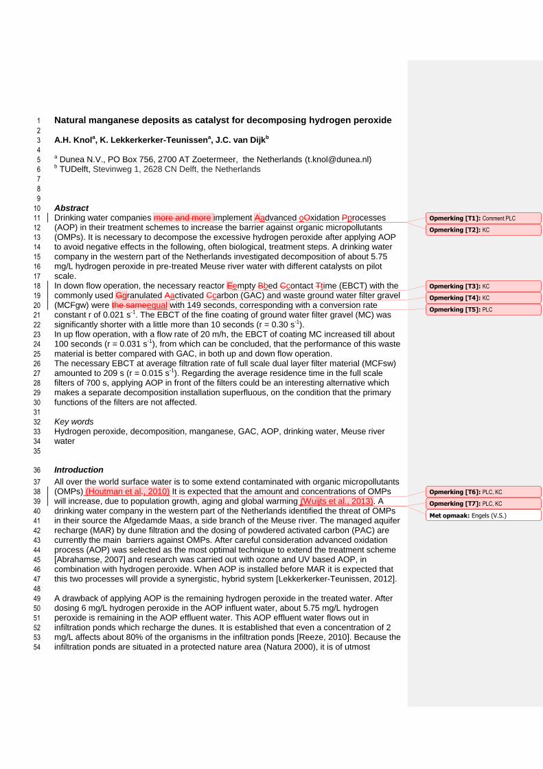
Table 1: Specifications of different tested filter gravels 143
144
Parameter Unit Course gravel MCFgw
Coating MC
Anthracite/sand, MCFsw
10% Grain mm 1.01 0.25 2.06/0.97
Uniformity 60%/10% - 2.26 2.02 1.18/1.13
Manganese content g/kg 14.0 100.0 0.15/0.09
145
146
Analyses 147
The hydrogen peroxide concentration in water was analysed on site with a 148
spectrophotometer. The measurement is based on the reaction of hydrogen peroxide with 149
titanium(IV)oxysulphate solution, following DIN 38409 H15. Samples were collected and 150
measured in a volumetric flask, after adding 5.0 ML of the titanium(IV)oxysulphate solution 151
by a pipette. When higher concentrations were expected than 6 mg/L, the samples were 152
diluted with milli-q water. The samples were measured at a wavelength of 420 nm and 153
corrected for background absorbance, which were determined by analysing the samples 154
Met opmaak: Engels (V.S.)
Met opmaak: Engels (V.S.)
Met opmaak: Engels (V.S.)
Opmerking [T14]: PLC
Met opmaak: Engels (V.S.)
Met opmaak: Engels (V.S.)
Met opmaak: Engels (V.S.)
Met opmaak: Engels (V.S.)
Opmerking [T15]: PLC
Opmerking [T16]: PLC
Met opmaak: Kop 2
Met opmaak: Kop 2
Met opmaak: Kop 2
Met opmaak: Kop 2
Met opmaak: Kop 2

4
without the addition of titanium(IV)oxysulphate solution. At a hydrogen peroxide 155
concentration of 5.8 mg/L the standard deviation σ was 0.02 mg/L. 156
157
Results and discussion 158
Activated carbon 159
With GAC in down flow operation, 5 mg/L hydrogen peroxide was decomposed completely in 160
just more than 120 s empty bed contact time (EBCT), see Figure 1. In the same EBCT, 10 161
mg/L hydrogen peroxide was decomposed for about 90 %. This experiment confirmed that 162
activated carbon is well-functioning catalyst for decomposing hydrogen peroxide, even at the 163
low water temperature of 1.8 °C. 164
165
0,0
1,0
2,0
3,0
4,0
5,0
6,0
7,0
8,0
9,0
10,0
0 50 100 150 200
H2O
2 in
mg
/L
EBCT in s
5 mg/L
10 mg/L
166 167 Figure 1: Decomposition of hydrogen peroxide with ROW 0.8 cat in R20 (bed height 1.4 m, flow rate 168 40 m/u, water temperature 1.8 °C) 169
170
Manganese coated filter material 171
Specifications 172
The manganese content of MCFgw is about 100 times higher than from MCFsw due to the 173
higher manganese concentration in groundwater (Table 1). The specific surface area is twice 174
as high. MC is characterized by a high manganese content and specific surface area and 175
small grain size. 176
177
Table 1: Specifications of different tested filter gravels 178
179
Parameter Unit Course gravel MCFgw
Coating MC
Anthracite/sand, MCFsw
10% Grain mm 1.01 0.25 2.06/0.97
Uniformity 60%/10% - 2.26 2.02 1.18/1.13
Manganese content gkg-1 14.0 100.0 0.15/0.09
Specific surface area* m2g-1 4.0 64 1.9/2.1
* BET surface area by N2 adsorption 180
Opmerking [T17]: KC
Opmerking [T18]: KC
Opmerking [T19]: KC
5
With XRD analysis, besides calcium and iron compounds, the manganese containing 181
compounds ramsdellite and birnessite were detected in MC (Hendrix, 2014). 182
Decomposition rate 183
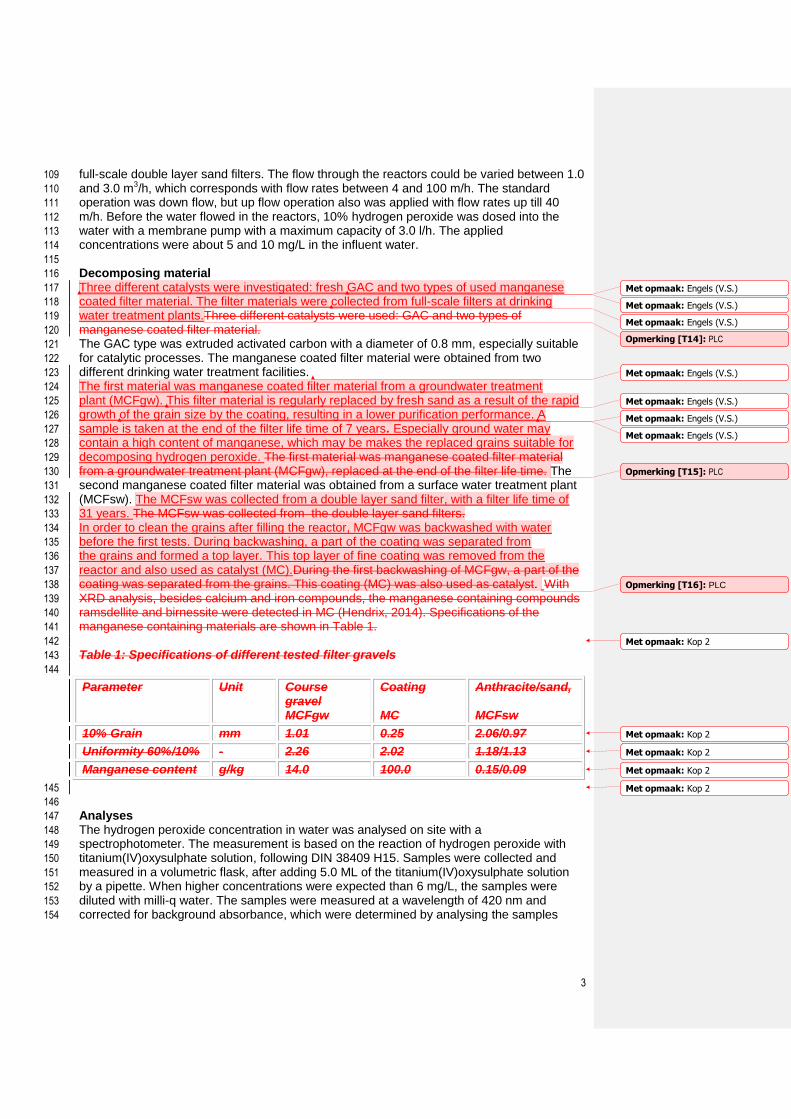
The decomposition rate of the different manganese containing materials are investigated in 184
down flow operation. The decomposition of 5 mg/L hydrogen peroxide with anthracite and 185
gravel MCFsw is plotted in Figure 2. 186 187
0,0
1,0
2,0
3,0
4,0
5,0
6,0
7,0
8,0
9,0
10,0
0 100 200 300 400
H2O
2 i
n m
g/L
EBCT in s
H = 0.85 m
H = 1.25 m
188 189 Figure 2: Decomposition over MCFsw in R60s with a bed height of 0.85 m (0.6 m gravel 0.8–1.2 mm & 190 0.25 m anthracite 1.4-2.4 mm) and a bed height of 1.25 m (1.0 m gravel 0.8–1.2 mm & 0.25 m 191 anthracite 1.4-2.4 mm), a flow velocity of 4.4 m/h, and a water temperature of 12.4 °C 192
193
In about 250 till 350 s the hydrogen peroxide in both reactors was decomposed completely. 194
The EBCT of the 0.25 m anthracite layer was about 200 s, which means that the anthracite 195
had a major contribution to the decomposition. The total EBCT of 700 s of the 0.85 m bed 196
layer was the same as the average EBCT in the full scale filters, which means that at least 197
400 s EBCT remains for the primary functions of the rapid sand filters (removal of iron and 198
manganese, nitrification and mineralization). This observation confirms that applying AOP in 199
front of the rapid sand filters can be an interesting option in practice and could make a 200
separate decomposing installation superfluous, provided that the primary filter functions are 201
not disturbed. 202
Decomposing with the coarse gravel MCFgw was investigated with a dose of 5 mg/L and 10 203
mg/L (Figure 3). 204
205
Opmerking [T20]: KC

6
0,0
1,0
2,0
3,0
4,0
5,0
6,0
7,0
8,0
9,0
10,0
0 100 200 300 400
H2O
2 i
n m
g/L
EBCT in s
5 mg/L
10 mg/L
206 207 Figure 3: Decomposition over MCFgw in R40 (bed height 2.3 m, flow rate 25 m/h, water temperature 208 3.3 °C) 209
210
A dose of 5 mg/L hydrogen peroxide was completely decomposed in an EBCT of 180 s. A 211
dose of 10 mg/L was decomposed in 260 s. Despite the manganese content of MCFgw of 14 212
gkg-1, about 100 times higher compared to MCFsw, and twice as large specific surface area, 213
4.0 m2g-1 compared to 1.9/2.1 m2g-1, the difference in the decomposing time between 214
MCFgw and MCFsw was no more than 30%. Possibly a part of the manganese oxides in 215
MCFgw were enclosed and did not contribute to the decomposition.Despite the manganese 216
content of MCFgw of 14 g/kg, about 100 times higher compared to MCFsw, the difference in 217
the decomposing time between MCFgw and MCFsw was no more than 30%. 218
219
The results of decomposition with the fine coating MC was investigated with a dose of 5 mg/L 220
hydrogen peroxide and printed in Figure 4. 221
222
223 224
0,0
1,0
2,0
3,0
4,0
5,0
6,0
7,0
8,0
9,0
10,0
0 20 40 60 80 100
H2
O2
in
mg
/L
EBCT in s
Opmerking [T21]: KC
7
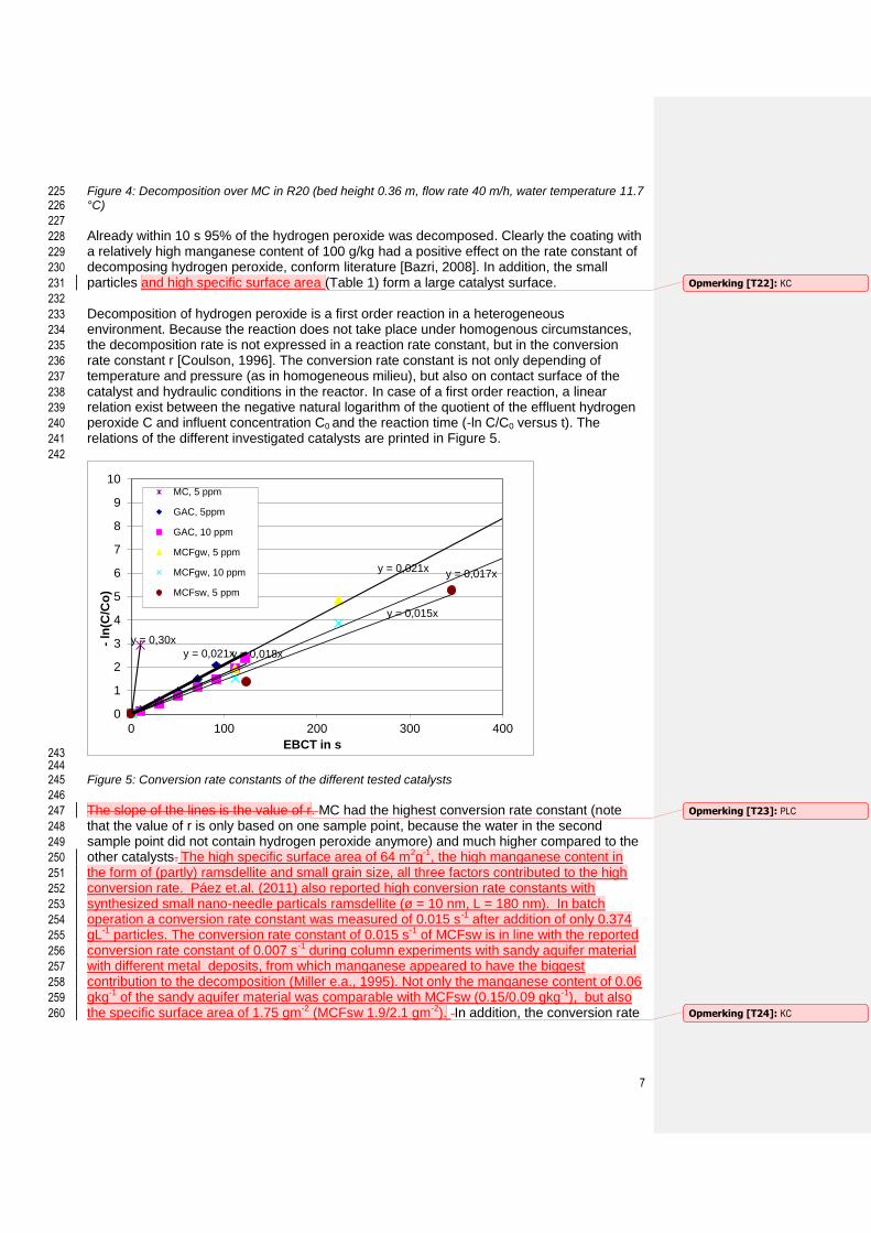
Figure 4: Decomposition over MC in R20 (bed height 0.36 m, flow rate 40 m/h, water temperature 11.7 225 °C) 226
227
Already within 10 s 95% of the hydrogen peroxide was decomposed. Clearly the coating with 228
a relatively high manganese content of 100 g/kg had a positive effect on the rate constant of 229
decomposing hydrogen peroxide, conform literature [Bazri, 2008]. In addition, the small 230
particles and high specific surface area (Table 1) form a large catalyst surface. 231
232
Decomposition of hydrogen peroxide is a first order reaction in a heterogeneous 233
environment. Because the reaction does not take place under homogenous circumstances, 234
the decomposition rate is not expressed in a reaction rate constant, but in the conversion 235
rate constant r [Coulson, 1996]. The conversion rate constant is not only depending of 236
temperature and pressure (as in homogeneous milieu), but also on contact surface of the 237
catalyst and hydraulic conditions in the reactor. In case of a first order reaction, a linear 238
relation exist between the negative natural logarithm of the quotient of the effluent hydrogen 239
peroxide C and influent concentration C0 and the reaction time (-ln C/C0 versus t). The 240
relations of the different investigated catalysts are printed in Figure 5. 241
242
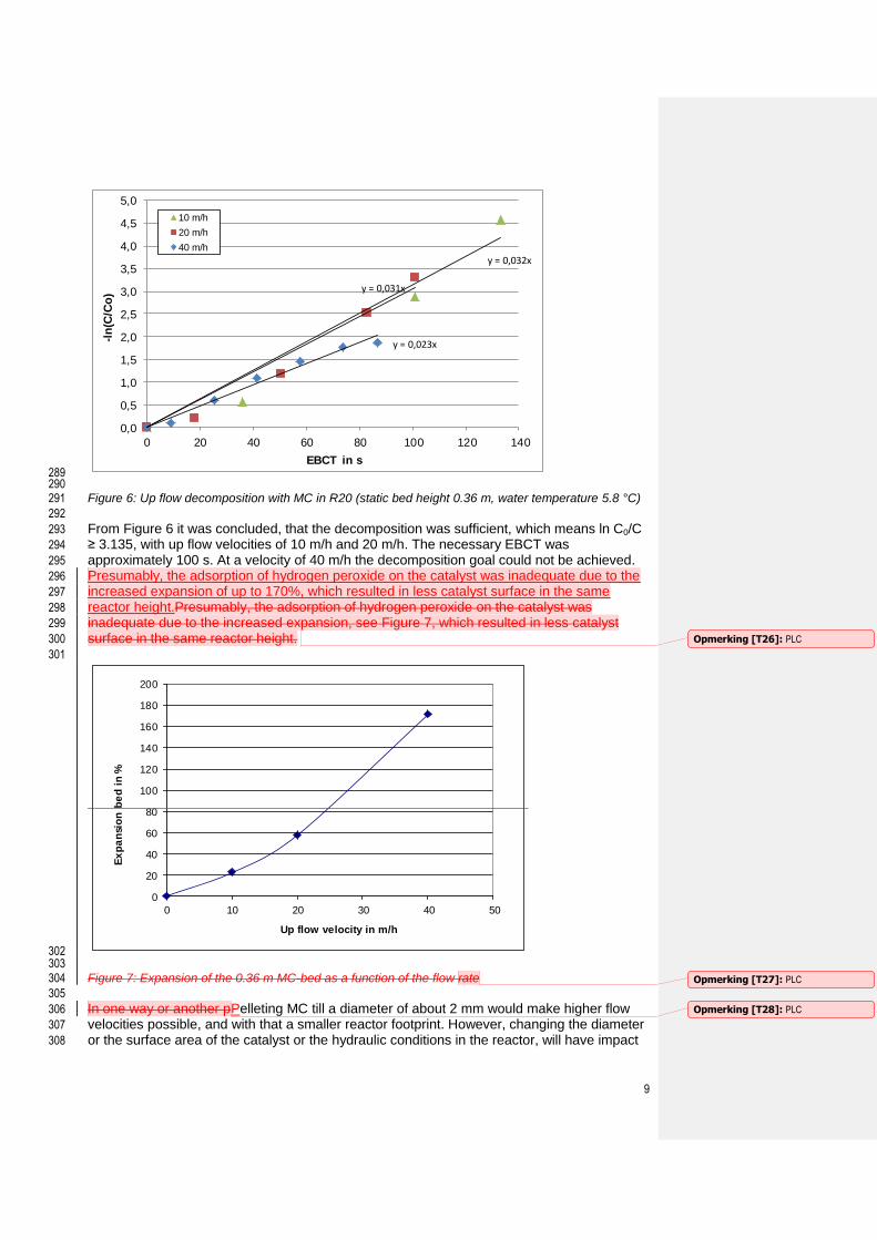
243 244 Figure 5: Conversion rate constants of the different tested catalysts 245
246
The slope of the lines is the value of r. MC had the highest conversion rate constant (note 247
that the value of r is only based on one sample point, because the water in the second 248
sample point did not contain hydrogen peroxide anymore) and much higher compared to the 249
other catalysts. The high specific surface area of 64 m2g-1, the high manganese content in 250
the form of (partly) ramsdellite and small grain size, all three factors contributed to the high 251
conversion rate. Páez et.al. (2011) also reported high conversion rate constants with 252
synthesized small nano-needle particals ramsdellite (ø = 10 nm, L = 180 nm). In batch 253
operation a conversion rate constant was measured of 0.015 s-1 after addition of only 0.374 254
gL-1 particles. The conversion rate constant of 0.015 s-1 of MCFsw is in line with the reported 255
conversion rate constant of 0.007 s-1 during column experiments with sandy aquifer material 256
with different metal deposits, from which manganese appeared to have the biggest 257
contribution to the decomposition (Miller e.a., 1995). Not only the manganese content of 0.06 258
gkg-1 of the sandy aquifer material was comparable with MCFsw (0.15/0.09 gkg-1), but also 259
the specific surface area of 1.75 gm-2 (MCFsw 1.9/2.1 gm-2). In addition, the conversion rate 260
y = 0,30x
y = 0,021x y = 0,018x
y = 0,021x y = 0,017x
y = 0,015x
0
1
2
3
4
5
6
7
8
9
10
0 100 200 300 400
- ln
(C/C
o)
EBCT in s
MC, 5 ppm
GAC, 5ppm
GAC, 10 ppm
MCFgw, 5 ppm
MCFgw, 10 ppm
MCFsw, 5 ppm
Opmerking [T22]: KC
Opmerking [T23]: PLC
Opmerking [T24]: KC

8
of the same catalyst depended on the initial hydrogen peroxide concentration. This 261
observation is reported earlier under heterogeneous conditions by Coulson [1996]. 262
In Table 2 the necessary EBCT is calculated for the investigated catalysts with an initial 263
concentration C0 = 5.75 mg/L (corresponding to a dose in the AOP influent of 6 mg/L) and an 264
effluent concentration C = 0.25 mg/L (the allowed concentration in the infiltration ponds), 265
which means that ln C0/C = 3.135 and t = 3.135/r. Here, it was assumed that the calculated 266
conversion rate constants at about 5.0 mg/L hydrogen peroxide will not differ much from the 267
conversion rate at 5.75 mg/L. 268
269 Table 2: EBCT of catalysts to decompose a peroxide concentration of C0 = 5.75 mg/L till C = 0.25 270 mg/L 271 272
Catalyst r (s-1) EBCT (s)
MCFsw 0.015 209
GAC 0.021 149
MCFgw 0.021 149
MC 0.30 10.4
273
The necessary EBCT in the full scale dual layer filters (MCFsw) amounts about 200 s. The 274
EBCTs of GAC and MCFgw equals about 150 s. The EBCT of MC is much lower with 275
approximately 10 s. 276
Mode of operation 277
278
All experiments were carried out in down flow operation. For full scale operation, however, 279
down flow operation over fine material has the disadvantage of fast clogging of filter material 280
with suspended particles and potential increase of the resistance due to oxygen bubble 281
formation, depending of the oxygen saturation degree of the water. These disadvantages 282
could be solved by up flow operation. 283
Up flow operation of the coating MC was investigated using three different flow rates. A flow 284
velocity of 40 m/h appeared to be the maximum velocity, without carrying the coatings with 285
the effluent of the reactor. The coatings became in fluidised state at a flow velocity of 4 m/h. 286
The decomposition of 5.8 mg/L hydrogen peroxide is plotted in Figure 6. 287
288
Opmerking [T25]: KC
9
y = 0,032x
y = 0,031x
y = 0,023x
0,0
0,5
1,0
1,5
2,0
2,5
3,0
3,5
4,0
4,5
5,0
0 20 40 60 80 100 120 140
-ln
(C/C
o)
EBCT in s
10 m/h
20 m/h
40 m/h
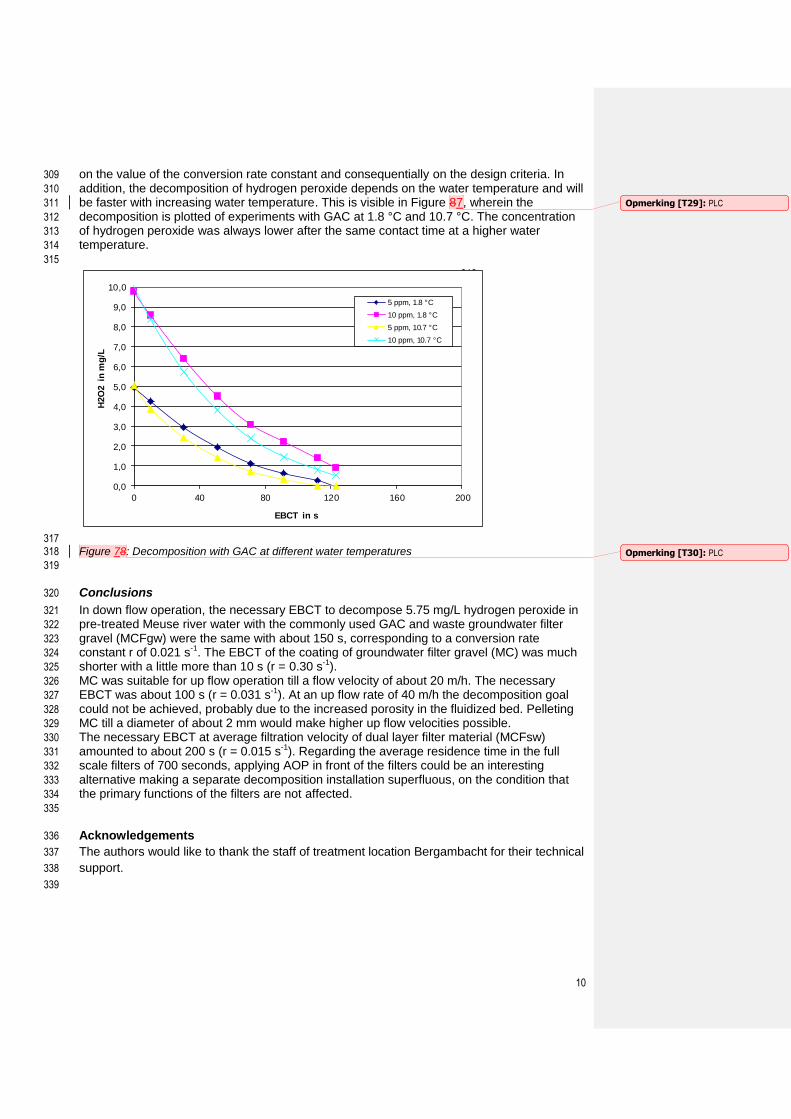
289 290 Figure 6: Up flow decomposition with MC in R20 (static bed height 0.36 m, water temperature 5.8 °C) 291
292
From Figure 6 it was concluded, that the decomposition was sufficient, which means ln C0/C 293
≥ 3.135, with up flow velocities of 10 m/h and 20 m/h. The necessary EBCT was 294
approximately 100 s. At a velocity of 40 m/h the decomposition goal could not be achieved. 295
Presumably, the adsorption of hydrogen peroxide on the catalyst was inadequate due to the 296
increased expansion of up to 170%, which resulted in less catalyst surface in the same 297
reactor height.Presumably, the adsorption of hydrogen peroxide on the catalyst was 298
inadequate due to the increased expansion, see Figure 7, which resulted in less catalyst 299
surface in the same reactor height. 300
301
0
20
40
60
80
100
120
140
160
180
200
0 10 20 30 40 50
Ex
pa
nsi
on
be
d i
n %
Up flow velocity in m/h
302 303
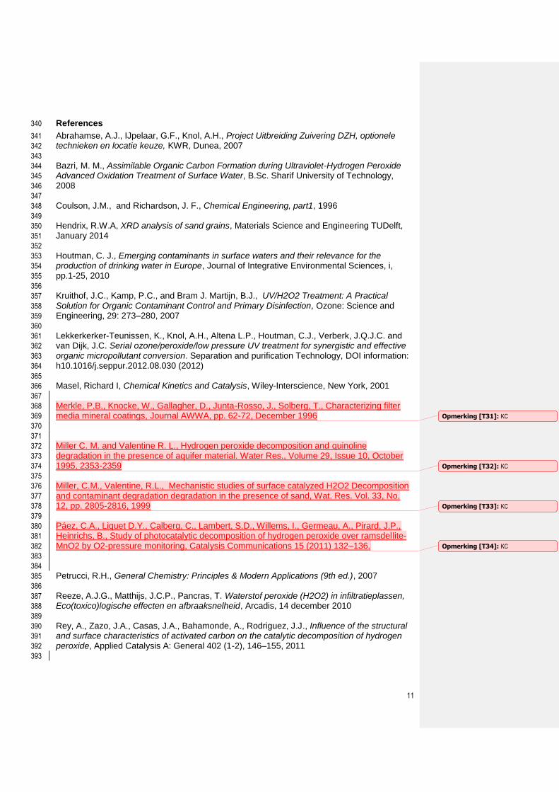
Figure 7: Expansion of the 0.36 m MC-bed as a function of the flow rate 304
305
In one way or another pPelleting MC till a diameter of about 2 mm would make higher flow 306
velocities possible, and with that a smaller reactor footprint. However, changing the diameter 307
or the surface area of the catalyst or the hydraulic conditions in the reactor, will have impact 308
Opmerking [T26]: PLC
Opmerking [T27]: PLC
Opmerking [T28]: PLC
10
on the value of the conversion rate constant and consequentially on the design criteria. In 309
addition, the decomposition of hydrogen peroxide depends on the water temperature and will 310
be faster with increasing water temperature. This is visible in Figure 87, wherein the 311
decomposition is plotted of experiments with GAC at 1.8 °C and 10.7 °C. The concentration 312
of hydrogen peroxide was always lower after the same contact time at a higher water 313
temperature. 314
315
316
317 Figure 78: Decomposition with GAC at different water temperatures 318
319
Conclusions 320
In down flow operation, the necessary EBCT to decompose 5.75 mg/L hydrogen peroxide in 321
pre-treated Meuse river water with the commonly used GAC and waste groundwater filter 322
gravel (MCFgw) were the same with about 150 s, corresponding to a conversion rate 323
constant r of 0.021 s-1. The EBCT of the coating of groundwater filter gravel (MC) was much 324
shorter with a little more than 10 s (r = 0.30 s-1). 325
MC was suitable for up flow operation till a flow velocity of about 20 m/h. The necessary 326
EBCT was about 100 s (r = 0.031 s-1). At an up flow rate of 40 m/h the decomposition goal 327
could not be achieved, probably due to the increased porosity in the fluidized bed. Pelleting 328
MC till a diameter of about 2 mm would make higher up flow velocities possible. 329
The necessary EBCT at average filtration velocity of dual layer filter material (MCFsw) 330
amounted to about 200 s (r = 0.015 s-1). Regarding the average residence time in the full 331
scale filters of 700 seconds, applying AOP in front of the filters could be an interesting 332
alternative making a separate decomposition installation superfluous, on the condition that 333
the primary functions of the filters are not affected. 334
335
Acknowledgements 336
The authors would like to thank the staff of treatment location Bergambacht for their technical 337
support. 338
339
0,0
1,0
2,0
3,0
4,0
5,0
6,0
7,0
8,0
9,0
10,0
0 40 80 120 160 200
H2O
2 i
n m
g/L
EBCT in s
5 ppm, 1.8 °C
10 ppm, 1.8 °C
5 ppm, 10.7 °C
10 ppm, 10.7 °C
Opmerking [T29]: PLC
Opmerking [T30]: PLC
11
References 340
Abrahamse, A.J., IJpelaar, G.F., Knol, A.H., Project Uitbreiding Zuivering DZH, optionele 341
technieken en locatie keuze, KWR, Dunea, 2007 342
343
Bazri, M. M., Assimilable Organic Carbon Formation during Ultraviolet-Hydrogen Peroxide 344
Advanced Oxidation Treatment of Surface Water, B.Sc. Sharif University of Technology, 345
2008 346
347
Coulson, J.M., and Richardson, J. F., Chemical Engineering, part1, 1996 348
349
Hendrix, R.W.A, XRD analysis of sand grains, Materials Science and Engineering TUDelft, 350
January 2014 351
352
Houtman, C. J., Emerging contaminants in surface waters and their relevance for the 353
production of drinking water in Europe, Journal of Integrative Environmental Sciences, i, 354
pp.1-25, 2010 355
356
Kruithof, J.C., Kamp, P.C., and Bram J. Martijn, B.J., UV/H2O2 Treatment: A Practical 357
Solution for Organic Contaminant Control and Primary Disinfection, Ozone: Science and 358
Engineering, 29: 273–280, 2007 359
360
Lekkerkerker-Teunissen, K., Knol, A.H., Altena L.P., Houtman, C.J., Verberk, J.Q.J.C. and 361
van Dijk, J.C. Serial ozone/peroxide/low pressure UV treatment for synergistic and effective 362
organic micropollutant conversion. Separation and purification Technology, DOI information: 363
h10.1016/j.seppur.2012.08.030 (2012) 364
365
Masel, Richard I, Chemical Kinetics and Catalysis, Wiley-Interscience, New York, 2001 366
367
Merkle, P.B., Knocke, W., Gallagher, D., Junta-Rosso, J., Solberg, T., Characterizing filter 368
media mineral coatings, Journal AWWA, pp. 62-72, December 1996 369
370
371
Miller C. M. and Valentine R. L., Hydrogen peroxide decomposition and quinoline 372
degradation in the presence of aquifer material. Water Res., Volume 29, Issue 10, October 373
1995, 2353-2359 374
375
Miller, C.M., Valentine, R.L., Mechanistic studies of surface catalyzed H2O2 Decomposition 376
and contaminant degradation degradation in the presence of sand, Wat. Res. Vol. 33, No. 377
12, pp. 2805-2816, 1999 378
379
Páez, C.A., Liquet D.Y., Calberg, C., Lambert, S.D., Willems, I., Germeau, A., Pirard, J.P., 380
Heinrichs, B., Study of photocatalytic decomposition of hydrogen peroxide over ramsdellite-381
MnO2 by O2-pressure monitoring, Catalysis Communications 15 (2011) 132–136. 382
383
384
Petrucci, R.H., General Chemistry: Principles & Modern Applications (9th ed.), 2007 385
386
Reeze, A.J.G., Matthijs, J.C.P., Pancras, T. Waterstof peroxide (H2O2) in infiltratieplassen, 387
Eco(toxico)logische effecten en afbraaksnelheid, Arcadis, 14 december 2010 388
389
Rey, A., Zazo, J.A., Casas, J.A., Bahamonde, A., Rodriguez, J.J., Influence of the structural 390
and surface characteristics of activated carbon on the catalytic decomposition of hydrogen 391
peroxide, Applied Catalysis A: General 402 (1-2), 146–155, 2011 392
393
Opmerking [T31]: KC
Opmerking [T32]: KC
Opmerking [T33]: KC
Opmerking [T34]: KC
12
Wuijts, S., van der Grinten, E., Meijers, E., Bak-Eijsberg, C.I., Zwolsman, J.J.G, Impact of 394
climate change on surface water as a resource for drinking water: From problem areas to 395
measures, Dutch Ministry of Infrastructure and Environment, 2013 396
397
IJpelaar, G, Robuustheid van de zuivering bij DZH, Management samenvatting prioritaire 398
stoffen 2005-2007, 2008 399
Met opmaak: Engels (V.S.)
Met opmaak: Engels (V.S.)
Met opmaak: Engels (V.S.)
Opmerking [T35]: PLC, KC