Embed Size (px)
Citation preview

NAU Hydraulic Testing System
2015
HYDRAULIC TESTING CORPORATION (HTC) BRANDON SCHMALZEL, MARIAH PAZ, BENOIT COUSINEAU COTE, YOUSEF AL AQUEEL, AND ALI ABDULLAH
HYDRAULIC TESTING CORPORTATION (HTC) |

1
1.0 Project Overview
1.1 Introduction The Hydraulics Testing Team (HTC) has produced a self-supporting hydraulics testing system that can demonstrate hydraulic principles, such as hydraulic head, flow rates, pressures, and more. The system is primarily designed for the professors and students of the hydraulics and fluid mechanics courses at Northern Arizona University (NAU). The Water Resources I course (CENE 333) currently designs a “Guerilla Project,” where the students design their own hydraulics experiment, in which they test one or multiple hydraulic parameters. One of the current issues with this project is that the students perform their experiments inside and create spill hazards. A second issue is that the students are unable to get adequate head to test some of their projects.
For this reason, the system is designed to be portable and easy to manipulate for students and professors. This allows for the system to be easily relocated to classrooms and outside areas on NAU’s campus. In addition, the system is designed to allow for a diversity of interchangeable hydraulics parts to be tested. Along with the structural system, HTC designed a hydraulic experiment to illustrate how the hydraulic testing system can be used. The hydraulic experiment uses valves, piezometers, and fittings to analyze all the concepts involved in the Bernoulli Equation. The general goal of this project was to produce a self-supporting hydraulics system and experiment that can be used by NAU’s hydraulics and fluid mechanics courses. 1.2 Limitations and Constraints One constraint was the price limit of $1,000 for all building and material costs of the hydraulic apparatus system. HTC pushed to design the system within the required budget by reusing materials found around NAU’s Facility Services department. The estimated total cost of the project was $1,200. 15% was added to this total cost for other contingencies.

2
2.0 Developing Required Parameters
The needs and requirements of the stakeholders were first assessed to assure that all variables of the project were met. The team and stakeholders immediately developed the following requirements of the project:
1 minute hydraulic testing time Free-standing system Structural material must be steel Interchangeable hydraulic parts Test free-falling head and constant head Use piezometers to analyze pressure
After developing the following general parameters of the project, HTC was able to begin the brainstorming process of the design.

3
3.0 Design HTC developed various designs throughout the design stage. These designs evolved into the final result that met all requirements of the stakeholders. 3.1 Design 1
The first design developed involved the hydraulic testing apparatus system scaling down from the roof of the NAU Engineering Building. This required the use of the roof on the east side of the building as shown in Figure 1 below. The top reservoir would be set on top of the roof and a lower reservoir placed on the bottom. The pipe system would run along the wall and a pump would push the water from the bottom reservoir back to the top.
Figure 1: East Wall of the NAU Engineering Building
The issue with this design was that HTC could not get immediate roof access permission from NAU Facility Services for the Fall 2015 semester. However, this is still a possible design for future senior Capstone projects.
3.2 Design 2 The second design developed involved the hydraulic testing apparatus system scaling down from the side bridge that connects the second story NAU Engineering Building and NAU Forestry Building (Figure 2). A tall trash container would act as the top reservoir at the top of the bridge and the hydraulic system would scale down the wall of the bridge. A bottom reservoir would be set at the bottom with a pump that would send the water back to the top reservoir.

4
Figure 2: Bridge Connecting the NAU Engineering Building and the NAU Forestry Building
One issue with this design was that it was not free standing and the system did not create its own head. Another issue was that the material of the trash container would not last a long period of time. 3.3 Design 3 The third design developed involved two structural systems with the hydraulic system connected to it (Figure 3). One system was the prototype that can be taken inside classrooms and is one half the size of the larger system. The second system would be the larger outdoor system. This design would contain two levels of scissor jacks that would allow the systems to create enough head and be freestanding.
Figure 3: Structural Hydraulic Testing System
5
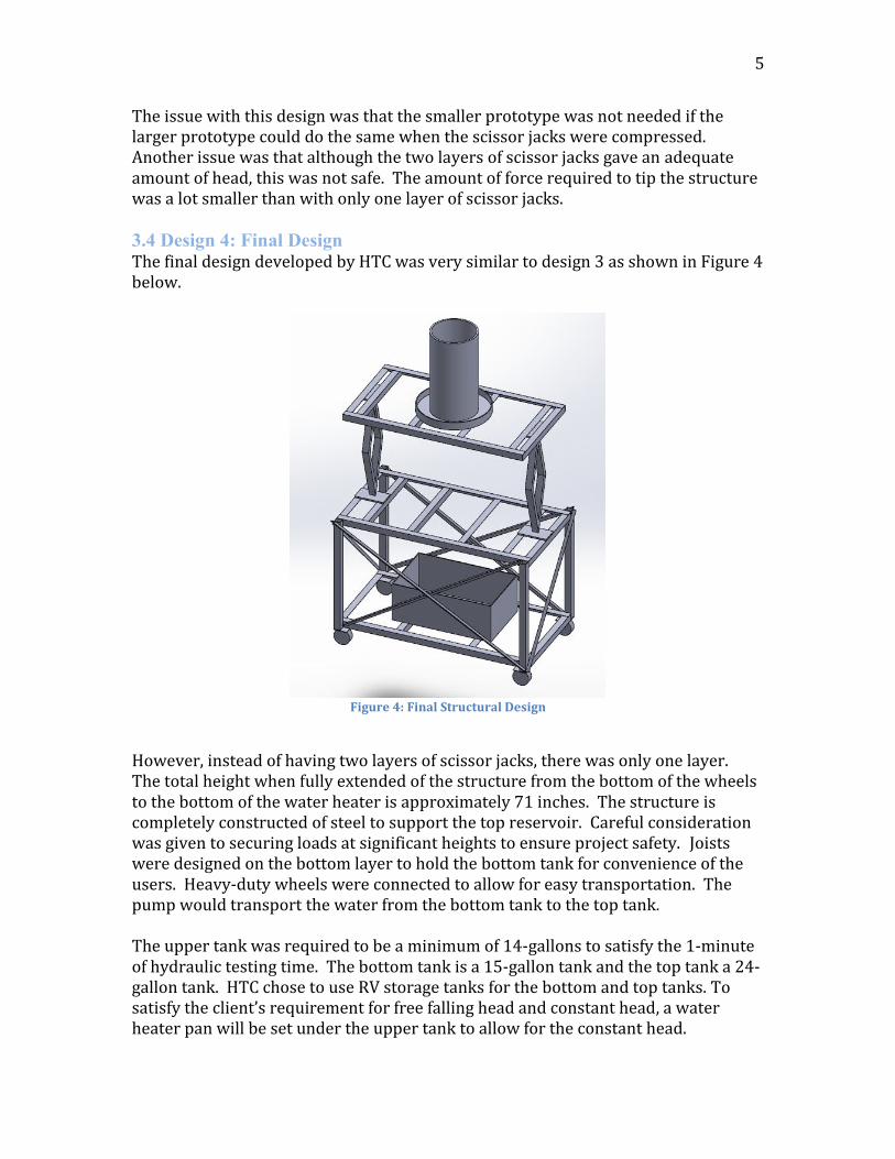
The issue with this design was that the smaller prototype was not needed if the larger prototype could do the same when the scissor jacks were compressed. Another issue was that although the two layers of scissor jacks gave an adequate amount of head, this was not safe. The amount of force required to tip the structure was a lot smaller than with only one layer of scissor jacks. 3.4 Design 4: Final Design The final design developed by HTC was very similar to design 3 as shown in Figure 4 below.
Figure 4: Final Structural Design
However, instead of having two layers of scissor jacks, there was only one layer. The total height when fully extended of the structure from the bottom of the wheels to the bottom of the water heater is approximately 71 inches. The structure is completely constructed of steel to support the top reservoir. Careful consideration was given to securing loads at significant heights to ensure project safety. Joists were designed on the bottom layer to hold the bottom tank for convenience of the users. Heavy-duty wheels were connected to allow for easy transportation. The pump would transport the water from the bottom tank to the top tank. The upper tank was required to be a minimum of 14-gallons to satisfy the 1-minute of hydraulic testing time. The bottom tank is a 15-gallon tank and the top tank a 24-gallon tank. HTC chose to use RV storage tanks for the bottom and top tanks. To satisfy the client’s requirement for free falling head and constant head, a water heater pan will be set under the upper tank to allow for the constant head.

6
The hydraulic system was designed following the structural system and can be seen in Figure 5 below. The water pipe system was required to contain piezometers, valves, fittings, and a pump. The first pipe output is fixed from the upper tank, however, it is flexible and the students can design their water system the way they desire following the first pipe output.
Figure 5: Hydraulic System
The pipe system in Figure 6 displays the path of the system. The piezometers are marked with heights and allow for the pressure to be easily measured. The valves allow for the experiment to be testing through either side of the system desired.

7
Figure 6: Hydraulic System

8
4.0 Purchasing and Construction
4.1 Purchasing Quality materials were obtained by HTC that meet the design parameters. The construction was dependent upon the steel for the structure, so that was the first material purchased. HTC found the steel for a reasonable price at a local steel manufacture in Flagstaff called Mayorga’s Welding. The sizes and quantity of steel needed was given to the manufacturer and the parts were easily available pre-cut two days later. All other parts for the structure were ordered through online sources because the parts were unavailable locally. The parts for the water system were purchased easily through Home Depot. The price list of the parts is shown in Figure 7 below. As shown, the total price of the system was kept below the $1,000 budget.
EXPENSES
Structure Expenses Item Qty Cost
2"x2"x1/8" steel angles 824" length 824 in. $ 206.00
1"x1"x1/8" steel angles 187" length 187 in. $ 56.10
2"x2"x0.2" square tubing 36" length 4 $ 40.00
3/4"x4ftx8ft plywood 3 $ 149.94
1/4" bolt 50 $ 8.57
1/4" nut 50 $ 6.00
30" scissor jack 2 $ 86.98
5" caster wheels 4 $ 180.84
Tools and Equipment $ 33.36
Total Structure Cost
$ 767.79
Piping Systems Expenses Qty Cost
15 Gallon Drum Tank 1 $ 99.99
26 Gallon Tank 1 $ 130.09
1/2" Lock PVC Fitting 20 $ 40.00
1/2" PVC Piping 30 ft $ 9.00
960GPH Pond Pump 1 $ 140.55
Overflow Drain Pan 1 $ 29.99
Tubing 2 $ 30.32
Total Piping System
$ 479.94
Total Project Cost $ 1,247.73

9
4.2 Construction All materials and construction occurred at the CECMEE Field Station on the south end of NAU. No major tool purchases were required, as they were available by NAU. The construction process began laying out the steel angles and determining where holes needed to be drilled in order to properly build the structure. After carefully measuring and marking each steel component, the team punched and drilled the holes using a drill press. Each of the three platforms of the structure were then laid out and assembled using only nuts and bolts. Holes were drilled into the square tubing and the structure began to take form. At this point, the structure was assembled minus the scissor jacks, cross braces, and casters. However, the structure was shaky and had little strength as the joint strength was only provided by the small ¼” bolts. The next step of the construction process involved using Metal Inert Gas (MIG) welding to fuse the steel together as one piece. Welding adds structural strength and rigidity and was completed only after a level confirmed each component was perfectly horizontal or vertical. The scissor jacks arrived shortly after this initial welding phase was complete. The team used an angle grinder to remove paint from scissor jacks’ feet so they could be welded to the second and third platform of the structure. Cross braces were measured and cut and finally welded to the structure. The cross braces were added in a slightly different fashion from the original CAD design to allow access to the bottom reservoir. The structure was then tipped on its side and steel plates were drilled and then welded under the four vertical square tubing sections. The caster wheels were then bolted to this steel plate. Applying paint was the last phase of construction for the structure. Paint helps to prevent the oxidation and deterioration of the steel, which is especially important for steel that is often exposed to water. The structure was first angle grinded to ensure each surface was smooth and no sharp edges remained. The Team then cleaned the steel with wet rags to remove any existing oxidation. A coat of primer was then added to every exposed surface of the steel. Finally, a coat of blue was added to the steel after the primer dried, and yellow was spray painted onto the scissor jacks. These colors were picked to match the school colors of NAU. Once the structure was completed, work began on the water system. First, plywood was cut to size and added to each of the three platforms of the structure. Top and bottom tanks were added and secured to the structure, as well as an overflow tray which fit on top of the plywood and under the top tank. Pipe fittings and valves were added to the tanks to allow for connections of pipe systems to the unit. A hole was cut into the bottom tank so that a 960 gallons per hour pump could be placed in. Black tubing was connected to the outflow of the pump and ran up to the top tank. Additional pipe fittings and tubing were connected to the outflow tray leading to the bottom reservoir. A pipe system designed by The Team with piezometers was added

10
using the connection at the top reservoir. This enabled the team to complete an operational and comprehensive test of the unit.
(This space intentionally left blank.)

11
5.0 Testing and Analysis 5.1 Structure Analysis Structural analysis was computed to determine the tipping moment located at the center of mass. This calculation was preformed to identify the force that a student or professor could apply on the structure to tip it. Tipping of the structure could perhaps damage the area around it or even injury a student or professor. Figure 7 shows the structure with applied forces and moments. The calculations below shows the process that was used to find the tipping moment of the structure. As seen in the calculations, it would take approximately 756 pounds to tip the structure above its center of mass. This is a sufficient because it would take couple of people to tip the structure. Calculations preformed for the tipping moment: Step 1: Find 𝑀1
𝑀1 = 𝐹𝑇 ∗ 18" Step 2: Find 𝑀2
𝑀2 = 800 𝑙𝑏 ∗ 17" Step 3: Set the moment equal to each other
𝑀1 = 𝑀2 Step 4: Plug in the values and solve for 𝐹𝑇
𝐹𝑇 = (800 𝑙𝑏) ∗(17")
18"
Step 5: Final solution
𝐹𝑇 = 756 𝑙𝑏
Figure 7: Tipping moment diagram

12
5.2 Water System Analysis The analysis preformed on the water system was mainly used to determine the appropriate reservoir size and pump power for the system. Equations 1 through 5 show the appropriate equations used to find the hydraulic deliverable of the water system [1]. Equation 1: Kinetic Energy equal Potential energy
𝟏
𝟐𝐦𝐕𝟐 = 𝐦𝐠𝐡
𝑽 = 𝑽𝒆𝒍𝒐𝒄𝒊𝒕𝒚 𝒐𝒇 𝒕𝒉𝒆 𝒇𝒍𝒖𝒊𝒅 𝒎 = 𝒎𝒂𝒔𝒔 𝒐𝒇 𝒕𝒉𝒆 𝒇𝒍𝒖𝒊𝒅 𝒈 = 𝑮𝒓𝒂𝒗𝒊𝒕𝒚 𝒉 = 𝒉𝒆𝒂𝒅
Equation 2: Velocity in a free-falling system
𝐕 = √𝟐𝐠𝐡 𝑽 = 𝑽𝒆𝒍𝒐𝒄𝒊𝒕𝒚 𝒐𝒇 𝒕𝒉𝒆 𝒇𝒍𝒖𝒊𝒅 𝒈 = 𝑮𝒓𝒂𝒗𝒊𝒕𝒚 𝒉 = 𝒉𝒆𝒂𝒅
Equation 3: Area of a pipe
𝐀 =𝐝𝟐𝛑
𝟒
𝑨 = 𝑨𝒓𝒆𝒂 𝒐𝒇 𝒂 𝒑𝒊𝒑𝒆 𝒅 = 𝑫𝒊𝒂𝒎𝒆𝒕𝒆𝒓 𝒐𝒇 𝒕𝒉𝒆 𝒑𝒊𝒑𝒆
Equation 4: Continuity Equation
𝑄=𝑉𝐴 𝑄= Flowrate 𝑉= Velocity A= Area of the pipe
Equation 5: Pressure Equation
𝐏 = 𝟎. 𝟒𝟑𝟑 ∗ 𝐡 ∗ 𝐒𝐆 P= Pressure H=Head SG=Specific Gravity
Using these equations, the team was able to identify that the water system would be a tank with a minimum volume of 13 gallons, and a pump that produces a minimum of 733 gallons per hour. The team decided to purchase a pump that produces 750 gallons per hour and that can lift water approximately 7.5 feet. In addition to the purchasing of the pump, the team also purchased a top reservoir that can hold a volume of 15 gallons of water and a bottom reservoir that holds 26 gallons of water. Table 1 shows the values that were assumed and solved for to identify these deliverables.

13
Table 1: Hydraulic Calculations
Hydraulics Calculations
Pipe Area (in) 0.20
Pressure (psi) 2.69
Flowrate (gph) 733.53
Testing Time (s) 63.8
Assumed Pipe Diameter (in) 0.50
Height (ft) 6.2
Reservoir Volume (gallons) 13
5.3 Water System Testing Testing of the water system was preformed once all of the parts were installed onto the structure. When testing, the team noticed that the calculated pump that produced 750 gallons per hour was not sufficient to lift enough water to the top reservoir and allow it to overflow. This meant that pump needed to be adequately larger than the flowrate leaving the pipe systems. The team decided to purchase a large pump that could produce more flowrate at the maximum elevation. A pump with a flowrate of 960 gallons per hour and a lift power of approximately 12 feet produced carries enough water to the top reservoir to overflow the 15 gallon tank. The water system and structure was then given to the professor of CENE 333 Water Resources 1 Alarick Reiboldt. The students of the course used the hydraulics testing system to present and test their individual hydraulic testing systems. The team observed and coop operated with the students and professor to test several hydraulic components. Below shows a list of hydraulic components that were successfully accomplished.
Piezometer Pinot tubes Change in velocity due to pipe diameter Change in velocity and flowrate due to change of head Friction losses from the different systems
14
6.0 Staffing and Cost of Engineering Service
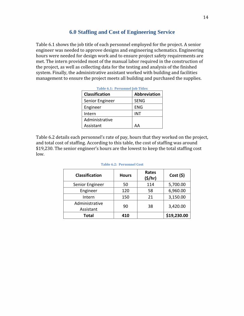
Table 6.1 shows the job title of each personnel employed for the project. A senior engineer was needed to approve designs and engineering schematics. Engineering hours were needed for design work and to ensure project safety requirements are met. The intern provided most of the manual labor required in the construction of the project, as well as collecting data for the testing and analysis of the finished system. Finally, the administrative assistant worked with building and facilities management to ensure the project meets all building and purchased the supplies.
Table 6.1: Personnel Job Titles
Classification Abbreviation
Senior Engineer SENG
Engineer ENG
Intern INT
Administrative Assistant AA
Table 6.2 details each personnel’s rate of pay, hours that they worked on the project, and total cost of staffing. According to this table, the cost of staffing was around $19,230. The senior engineer’s hours are the lowest to keep the total staffing cost low.
Table 6.2: Personnel Cost
Classification Hours Rates ($/hr)
Cost ($)
Senior Engineer 50 114 5,700.00
Engineer 120 58 6,960.00
Intern 150 21 3,150.00
Administrative Assistant
90 38 3,420.00
Total 410 $19,230.00

15
7.0 Acknowledgements
The HTC would like to acknowledge and thank the following personnel for their help, instructions and effort made to achieve the goals and objectives of the project. These personnel are Dr. Bridget Bero, E.I.T. Alarick Reiboldt and P.E Mark Lamer.
(This space intentionally left blank.)

16
8.0 References
[1] “Engineering ToolBox,” Engineering ToolBox. [Online]. Available at: http://www.engineeringtoolbox.com/. [Accessed: Dec-2015].
(This space intentionally left blank.)

17
8.0 Appendices
Figure 7: Design 1
Figure 8: Design 2

18
Figure 10: Original Gantt Chart
Figure 9: Design 3 (Final)

19
Figure 11: Current Gantt Chart