Embed Size (px)
Citation preview

. o - 2. . . + . -
-: -~- 4
"NAVAL AIRDEVELOPMENT
CENTERWARMINSTER. PA 18974
REPORT ho. NADC-72056-VT 8 JUW, 1972
SIMARY OF TEST RESULTS FOR ALRUINUM ALLffBOX B FATIGUE PROGRAM, TEST PHASES
I-IV
F"L REPOTAIR.ASK A320320Nj202B/2FO0422204
WORK UNIT NO. 3201
Approved for public release; distribution unlimited.
I 'I

1UNCLASS [FIE"
DOCUMENT CONTROL DATA. R & D
Air Vehicle Tecba-leogy Departmaent _ '_cjassifiee
* I~ *.Nonre
Summary oZ Test Results For Al"inum Alloy Box Beam Fazigue Program,Test Phases !-IV
-1 -40 El)jA 'T,- .- I p. rj ~ J.r. -.-
Final Report
WILLTI.A. M ,.YAN
Q ,•, t " . * O & " ; PIt ..I-
8 June 1972 4,' 1 8
•o,- ,, .�cWork Unit 1":. 3201 NADC-72056-Vr
""ion-
Approved fc- public release; distribution unlimited
.. a%..L A`.- Ss.:esns Command
Navy Dep3rtmentNone Wa0--itigton, D.C. 20360
The results of a four-phase fatigue program for bLnding tests of 7075-T6Saluminum alloy box beams for positive loadb onl, and for positive and negative
loads for both constant-and variabit-load azplittzd,:; are presented. The r,:lativedamaging effect of four airplane flight-maneuver-loads specrra uas determined,en-i the eff-Lcts on fatigue life for variaciors in spectrum block size, stress leve'.stress direction, and load sequencc were establishLd and the resuits reported on.
When compared to full-scale aircraft structure:: of like material under zonst.an-amplitude unidirectional loading on a percent of ultimate *trength basis the beamsrepresented th( upper bound of those data for full-scale structures and exhibitedsimilar fatigue characteristics. The beams were Lhus established as a suitableidealized structure for the investigation of those pa:-anetcrs whicil affect thestructuzral fatigue life.
The smallest feasibie block size should be used for the tests of full-scalcstructures. The 20-hour block size under f"ixed-seiuenc4 loading was found to mo:.tcloseiv sixnulite random-sequence loading, which approximate, in flight loading.
Qualitatively, the significant effects of tre parar-eter variations on fatiguelife can be attributed to the compressive residual stresIos produced at the edgesof the fastenc tioles by the application of the highest .,pectrum lords and thesubsequent changes that occur in these residua? stresses.
D , 147"3 UNA..! 1) ,DD S ... ", I','lASS 1FIED
"SN'f*. ,

UNCLASSIFIED
L'•N A r"tll•
Fatigue
Aluminum AlloysMetals
Box BeamsConstant-Amplitude TestsVariable-Amplitude Tests
"1 -
: I
II
I II I
II
Si 'I I-I
l I I pi
DDIo,,, 1473 ,:,-I1, 1o ,-I:CASII'

DEPARTMENT OF THE NAVYNAVAL AIR DEVELOPMENT CEN1ER
WARMINSTER. PA. 18974
Air Vehicle Technology Department
REPORT NO. NADC-72056-VT 8 June 1972
SUMMARY OF TEST RESULTS FOR ALUMINUM AILOY BOX BEAMFATIGUE PRIGRAM, TEST PHASES I-IV
FINAL REPORTAiRTASK A320320N/202B/2FO0422204
WORK UNIT 14O.3201
The results of a four-phase fatigue program for bending tests of 7075-T6aluminum-alloy box beams for positive loads only and for positive andnegative loads for both constant-and variable-load amplitudes arepresented. The relative damaging effect of four airplane flight-maneuver-loads spectra was determined, and the effects on fatigue life for variationsin sr-ectrum block size, stress level, stress direction, and load sequencewere established and the results reported on.
Reported ty: _ __ _ _ _
W. BREYA&Aerospace Engineer
/
Approved by: _ _ _ _ _
C. G/ -ERAssot(iate DirectorAero Structures Group
Approved for public release; distribution unlimited.
* I
''aIi'8
III :,

NADC- 72056-VT
TABLE OF CONTENTS
INTRODUCTION ..... . ... ... ° ............. 1
TEST SPECIMENS. . . . . . . . . . . . . . . . . . . . . . . . . 2
TEST PROGRAM . ............. ........... 3
1METOD . . . . . . . . . . . . . .. 4
RESULTS*. . . . . . . .. . . . . . . 6
CONCLUDING RE.. .. .. .. .. .... . 9
RECOUIINDATIONS . . .. . . . .. . .. . . ...... . 11
REFERENCES ......................... . 12

NADC- 72056-VT
LIST OF T"ABLES AND FIGURES
TABLES
NO. PAGE
1 Properties of Material and Beam Specimens .... ......... 13
2 Flight Loads Maneuver Spectra For 1,000 Hours ......... ..
3 Results of Static Failing-Load Tests ..... ............ ... 16
4 Fatigut- L~v.'s in Equivaic.nt Flight Hours for Lo-Hi Fixed-S.quenct. Positive Loads Fatigue Tests, Phase . ..... ...... j7
5 Fati-uv Lives in Equivalent Flight Hours For Randaini-S.-qu,-ncc-F.atigue Tests, Positive Loads, Phase .i ............ ...
6 Comparison of Average Fatigue Lives in Equivalenr FlighrHours for Random-and Fixe6d-Sequencc (Lo-!i]) Fatigue T.sts,Positive Loads Only . . . ................. 19
Results of Fatigue. Tests for Positive and Negative Loadsof MIL-A-8866 Spectra, Phast- III, 11% Margi,- of Safttv 20
8 Fatigtt- Lives in Equivalent Flight Hours For Positive rnedNegative Load (Full Spectrum) Fatigue Tests, Phase 711,117. Margin of Safety.... ........ .................. 23
9 Comparison of Average Fatigue Lives in Equival-nt Fli-ght ijoursfnr Positive Loads Only and for Full Spectrum Loads, !!Z Mar-,inof Safety.................. ............................. 24
10 Results of Fatigue Tests for Extended Str-ss-Lc':t-! and Bllock-Sizt- Rang•s, Phase WV, Positive Loads Only, Lo-Hi Fi::cd-Sequence Loadin. ................... . . . . 25
11 Fatigue Lives in Equivalent Flight Hours for .ExL.ndt-d Str-ss-Level and Block-Size Ranges, Phase IV, Positivv Loads OnyIv,Lo-Hi Fixed-Sequence Loading ............... .............. 26
Vi

NADC-7205-0-VT
LIST OF TABLES AND FIGURES (CONCLUDED)
FIGURES
NO. PA•-.
1 Box beam specimen design . .................. 27
2 Comparison of loading schematics for fixed-and random-sequencefatigue tests, MIL-A-8866 spectra, positive leads only. . ... 26
3 Schematic diagrams of fixed-sequence loading orders for positiveand negative load spectrum fatigue tests. . . . . . . . ... . . 29
4 Load vs. median-life curves, log-log plots. . ......... 30
5 Const3nt-life diagram for beams based on stresses ....... 31
6 Pictorial presentation of beam fatigue-life data for testspectra of MIL-A-8866, lo-hi fixed-sequence positive loadtests of Phase I .. .. . .................. 32
7 Pictorial presentation of beam fatigue-life data for random-and fixed-sequence fatigue tests. . .............. 33
8 Comparison of average fatigue lives for positive only andpositive and negative loads for MIL-A-8866 spectra, lo-hifixed-sequence loading, 11% margin of safety . . . . . . . . . 34
9 Comparison of average fatigue lives for positive only andpositive and negative loads for MIL-A-8866 spectra, random-sequence loading, 11% margin of safety .......... . 35
10 Effect of block size variation o life for limit load stressconditions, Spectrum A, positive loads only, lo-hi fixed-sequence loading. . . ........................ 6
11 Pictorial presentation of Spectrum A beam fatigue-life datafor extended stress level and block size ranges, Phase IV, positivepositive loads only, lc-hi fixed-sequence loading . . . . . . . 37
I
J!1

NADC- 72056-VT
INTRODUCTION
An initial fatigue investigation by the National Bureau of Standards(NBS), reference 1, resulted in the design of a simple box beam structureof 7075-T6 aluminum alloy. The load-lifetime results obtained in bendingfor this beam specimen fell within the scatter band of full-scale struc-tures data available at that time. A second fatigue investigationperformed by the NBS, reference 2, using box beams of identical designfurther established that the bending fatigue characteristics weresimilar to those of typical full-scale aircr3ft structures of the samematerial.
Because of the relative economy in fabrication, the speed in testing,and the apparent similarity in ch3racteristics between the beam structureand practical full-scale 7075-T6 aluminum alloy structures, an extensivestudy of the fatigue characteristics of the NBS designed 7075-T6 aluminum-alley box beams was undertaken in late 1960 by the Aero StructuresDepartment. This unit is now the Aero Structures Division of the AirVehicle Technology Department (AVTD). The proper definitiolu 'if para-meters affecting the life of a structure is essential to the attainmentof structural reliability, the primary goal in the design and analysisof aircraft structures.
It is impractical to test full-scale structures in sufficientquantity to obtain statistically valid data for parametric definitions;therefore, the establishment of the box beam pcgram fulfilled this need.
The overall objective of this investigation was to provide Ztruc-tural fatigue data that could be used in the design, analysis, and testof complete aircraft to obtain more assurance of structural reliability.Consrapt-and variable-amplitude fatigue tests were performed to determinethe follc, ing:
1. The shape of the load-lifetime curve at the extremely shortlife end.
2. The relative damaging effects of the manuver loads spectraspecified as spectra A, B, and C in reference 3 (MIL-A-8866).
3. The effects of the test spectrum block size.
4. The effect of stress level.
5. The effect of load sequence within each block.
6. The effect of stress reversals
Sj1

NADC-72056-VT
7. The validity of various cumulative damage hypotheses forpredicting the lives of structures.
The experimental work for the program was divided into four phases.
Phase I--Determination of constant-and variable-load-amplitudefatigue test data for unidirectional loading. Lo-hi fixed-sequenceloading was used for load spectrum tests.
Phase Il--Determination of effects on life due to randomizationof loads within the loading blocks for unidirectional loading. Loadspectrum tests were identical to those of Phase I except that the loadsequence within the loading blocks was randomized on a cycle by cyclebasis.
Phase Ill--Determination of effects on life of combined posi-tive and negative loading for constant-and variable-load-amplitudefatigue tests. Lo-hi and hi-lo fixed-sequence loading was used for theload spectrum tests. Randomization of loads on a cycle by cycle basiswithin the loading blocks was also investigated.
Phase IV--The determination of the effects on life of extendedblock size and limit-load-stress level ranges for Spectrum A under lo-hi,fixed-sequence unidirectional loading.
The Phases III and IV data are to be considered preliminary innature until final review and analysis is completed. A final reportwill be issued subsequent to this report which will contain the analysesof data for Phases III and IV and the entire program.
TEST SPECIMENS
The beams used in this program, as stated previously, were designedby the NBS. The design of. the test specimen is shown in figure 1.Design details of the beam are given in reference 4. The beam specimenrepresented a typical airframe structure with regard to material, fabri-cation process, and the presence of stress concentrations resulting fromconventional riveted construction.
The beams were fabricated from three separate lots of material,which was purchased from two different producers. Presumably, eachlot of material was from one batch and run of the alloy. All of thebeams were fabricated at the AVTD using conventional aircraft manu-facturing procedures; they were not handled or finished with the careand precision of material specimens. External defects in the material,such as nicks or scratches, were not removed.
2
NADC-72056-VT
Th- mechanical properties of the material of each lot were deter-mined by performing static tensile tests on at least three standardmaterial coupons cut from the beam cover plate material. Table 1 givesa comparison of typical properties obtained experimentally for materiallot 2, reference 5, with the standard handbook values of refeience 6.The beam sectional properties from reference 4 are also given in table 1.
The static strength for the batch of specimens fabricated fromeach material lot was determined by testing to static failure at leasttwo beams from each batch.
TEST PROGRAM
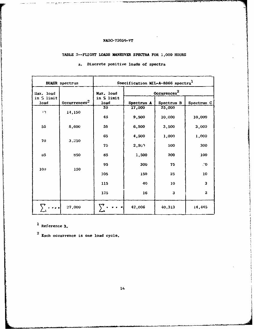
The overcil box beam program consisted of four test phases. Theexperimental work under Phases I and III was divided into threecategories: static-strength tests,constant-load-amplitude fatiguetests, and variable-load-amplitude fatigue tests. Phases II and IVconsisted only of variable-load-amplitude fatigue tests. The flightmaneuver loads spectra used in the program are shown in tables 2a and2b. The breakdown of these spectra into the load frequencies ir agiven block size and the manner of spacing the infrequently applied highloads within the spectra are detailed in references 4 and 7. Detailsof the test program for Phase I are contained in reference 3.
Statistically designed factorial experiments were used for perform -ing the variable-load-amplitude fatigue tests. The same factorial designwas used for performing the variable-load-amplitude Eatigue tests ofPhases I and II; a lo-hi fixed-sequence loading was used tor the Phase Itests and a cycle by cycle randomization of loads within the blocks wasused for the Phase II tests. A schematic depicting the fixed-and random-sequences is shown in figure 2. Details for the Phase I experiment arecontained in reference 3 and for the Phase II experiment in reference 8.
The details of the test program for the constant-load-amplitudefatigue tests of Phase III are contained in reference 5. A 3 x 3 x 3factorial experiment was used for the Phase III variable-load-amplitudefatigue tests for the full spectrum of positive and negative loads. Thefactors of block size (20, 60, and 100 equivalent flight hours), loadsequence (lo-hi and hi-lo fixed-sequence and random-sequence), and loadspectrum (Spectra A, B and C of MIL-A-8866) were investigated. Tworeplications were made for each test point, a total of 54 beams wasused for this phase. Figure 3 shows the loading orders used for thefixed-sequence tests.
3

NADC-72056-VT
A 4 x 3 factorial experiment was used for the variable-load-ampli-tude fatigue tests of Phase IV for Spectraum A. The factcr3 of blocksize (20, 100, 200, and 500 equivalent flight hours) and nominal limitload stress level (35, 45, and 54 KSI) were investigated. Two repli-cations were made for each test point; a total of 24 beams was requiredfor the experiment. However, lives of four beams were used fromPhase I tests; therefore, only 20 beams were actually tested for theexperiment. The nominal stress levels used in this phase were reducedto approach more closely those used in the design of aircraft structures.
The original test plan for this phase included tests for Spectra Band C, in addition to Spectrum A and for tests up to a 200 hour blocksize. However, these tests were eliminated due to funding limitationsand long times required for tests. Since only four test points (eightbeam tests) for the two spectra were completed, these data are notpresented because they were not sufficient for statistical analysis.
A total of 256 beams were used for the entire program. These wereallocated as follows: 7 for static-strength tests, 63 for constant-load-amplitude fatigue tests, and 186 for variable-load-amplitude fatiguetests (16 beams were included for retests). In addition, there were otherbeams that were used for special purposes such as for a local strain
investigation for Phase I and some for comparative tests for lot 3 beams.
METHOD
The beams were simply supported at the end; and loaded at the midspanby means of a hydraulic actuator. The method of supporting the beamsand reacting the beam loads at the ends of the beam were described inreference 4. The loading systems used for the Phase I tests wereadequately described in this reference.
For the random-sequence tests of Phase II, a fully automatic fatigue-loading system, which was specifically designed and purchased for theprogram, was used. This was a four-channel electro-hydraulic servovalve-controlled closed-loop automatic control system, the details are toundin references 7 and 8.
The tests to the full spectrum of positive and negative loads ofPhase III, with the exception of Spectrum B fixed-sequence tests, wereperformed using the automatic fatigue loading system used for the Phase IItests. However, the beams were tested singly due to the nature of theloading. In the random-sequence tests the loads were randomized cycle
4

NADC-72056-VT
by cycle across the positive and negative load portions of each block.The load frequencies within blocks were maintained the same as for thefixed-sequence tests.
The fixed sequence tests for Spectrum B of Phase III were performedusing an AVTO dynamometer-load-control system and an AVTD designed pro-grammer for applying the positive loads of the spectrum in a parallel-bt*an.arrangement. This system was the same as that used for the Phase I fixed-sequence tests and described in reference 4. 'he small number of infre-quently occurring negative loads in the spectrum were applied by meansof a hand-pump-operated hydraulic jack. For these tests only, the "0"
spectrum load as applied was equivalent to approximately a -57. negativelimit load due to a "0" load tare weight condition acting on the heamI.s.The effects on life of this condition were considered negligible.
The beams for Phase III were fabricated of material from lots 2 Fncd3. At the start of the program for the Phase I tests, the basis forest-ablishing the test loads for the variable-load-amplitude fatigue ,Žstswas the use of an average static failing load for all the beams te:;tedito failure by the NBS and the AVTD. This value was 6,860#. (See refer-ence 4). This value was anly slightly changed by the addition of beamsfailed from lot 2 and the beam loads for Phase I1 tests were maintainedthe same as for Phase I. The addition of the failing loads of the beamsfrom lot 3 to all previous failures reduced the average static failingload because the lot 3 values were the lowest iii ranking order, How-ever, again, to maintain consistency of loads througibout the programand because the change was not considered significant, the value of6,8604 for the average static failing load was maintained as the basisof determining the test loads for the variable-load-amplitude fatiguetests of Phase III for lot 3 beams.
For the variable-load-amplitude fatigue tests oi Phase III(exceptfor Spectrum B fixed-sequence tests) the loading rates for each levelof tLhe full spectrum of positive and negative loads were established togive a maximum strain rate during the load cycle of lO,00X4In!In./Sec.This same basis was used for the Phase !I tests and is further explainedin reference 8. However, due to difficulty with the response time ofload recording equipment, most tests were performed at one-half themaximum rate and some at less than one-half of maximum..
All of the tests for Phase IV of the program were performed usingthe automatic fatigue loading system and the two beam test setup foreach test point in a parallel-beam arrangement. The beams for these
5

NADC- 72056-VT
tests were from lot 3 material and, as discussed previously, for Phase IVloads were based on an average static failing load of 6,860#. Testlimit loads were based on a ratio of limit load stresses to the 0% M.S.limit load stress of Phase I as loads were proportional to stressesthroughout the stress range covered.
The objective was to use the same loading rate for all spectrum tests.Thus, the loading rates for the tests were established on developing thesame miximum strain rate during the load cycle klO,O00.(in./In./Sec.) aswas used for the tests of Phases II and III. A bar graph visual loadindicator system was developed during this test phase which enabled sometests to be performed developing the full strain rate. Other tests wereperformed at reduced rates.
RESULTS
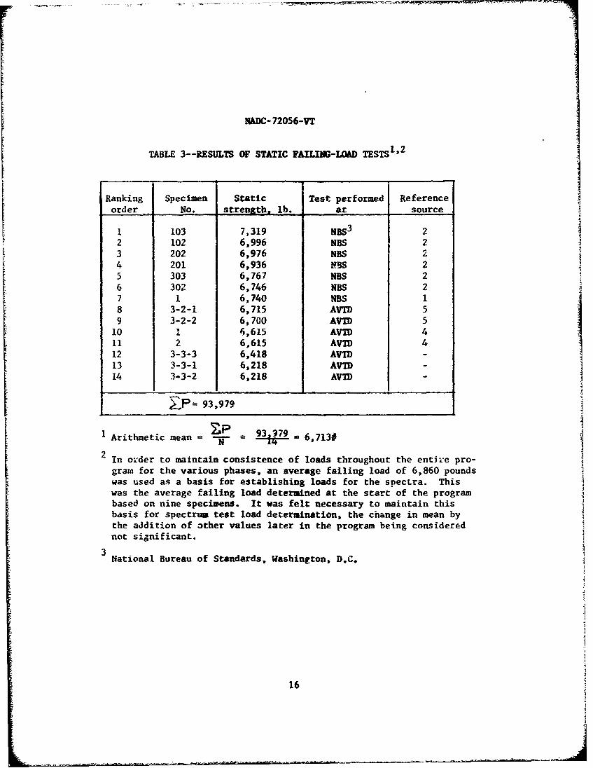
The results of all static failing-load tests for beams from the
various beam lots performed both by the NBS and the AVTD are given intable 3. The three last values in the tabl- are for beams that werefabricated fr.1,,t lot 3 material.
Three types of load-lifetime curves were developed during the pro-gram; one for loading from (+Ig to P), refereitce 4. one for loading from(-Ig to P) and one for a lg mean load (ig ±-P), reference 5. These datawhich are presented as a family of curves in reierence 5, are also repro-duced in figure 4. At the extreme short life end, (low cycle region) thecurves tend to become as-pmrotic to the line representing the static-strength of the structure. erom a family of load-lifetime curves basedon stresses in reference 5, a constant-life diagram babed on outer fibernominal stress was developed and is shown in figure 5. A comparison ofthe (+lg to P) load-lifetime curve for the beam structure with that forfull-scale aircraft structures, madc. of 7075-T6 aluminum alloy and testedat the AVIT) on the common basis of percent of static strength is presentedin reference 4. This comparison shows that the curve for the beam struc-ture is the outermost curve when compared to curves for full-scalestructures; that is, the beam fatigue lives are greater because it is anidealized structure.
The results, in equivalent flight hours to failure for the fixed-sequence, variable-load-amplitude fatigue tests of Phase I from refer-ence 4, are given in table 4. Detail results for each beam are alsogiven in this refecence. A pictorial presentation of these average lifedata showing the effects of the paranmcters investigated is shown in figure 6.
6
NADC-72056-VT
The BUAER spectrum was insensitive to the variations of both block sizeand stress level; therefore, it was not included in figure 6. A statis-tical analysis of the factorial experiment of Phase I, by means of theanalysis-of-variance method, is givren in appendix C of reference 4. Adiscussion of the effects of the various parameters on the fatigue lifeis also found in this reference. Qualitatively, the changes in fatiguelife due to variations in block size and nominal stress level can beattributed to the compeessive residual stresses developed at the edgesof the fastener holes and the rrdistributions of these stresses. Adetailed discussion of this is also contained in the reference.
The results for the random-sequence fatigue tests of Phase II fromreference 8 are summarized in table 5. A comparison of the averagefatigue lives for both the random-and fixed-sequence (lo-hi) fatigue testsis given in table 6. A pictorial presentation showing a superposition ofthe random-sequence data on the fixed-sequence data is shown in figure 7.for all of the test spectra. Reference 8 contains the statisticalanalyses of the factorial experiment for the random-sequence tests bythe analysis-of-variance method. Data from the Phase I fixed-sequencetests were combined with the random-sequence data of Phase II to studythe effects of load sequence. A discussion of the comparison ofrandom-and fixed-sequence loading is given in the reference.
The results of the Phase III fatigue tests for the positive and nega-tive loads of the MIL-A-8866 spectra are given ia table 7. It is notedthat for the hi-lo fixed-sequence testo, final failure occurred in allcases on the application of the Ist high load cycle (initial cycle ofblock) in the block where failure occurred. The specific loads in thespectrum at which beam failure occurred for the 54 beams tested oereas follows: 40 at 125% L.L., 10 at 115% L.L., I at 105% L.L., I at95% L.L. and 2 at 85% L.L. One of the 85% L.L. failures, was, however,due to an inadvertent overload to 125% L.L. while loading to the 85% L.L.level.
The individual lives to failure and the average life for each testpoint for the Phase IIl tests are given in table 8. The table showsthat a much shorter life is obtained for the fighter spectrum (Spectrum A)under a lo-hi than for a hi-lo order of loading for the fixed-sequencetests. Tables 9a and 9b show comparisons between the average fatiguelives for the full spectrum loads under fixed-and random-sequence loadingwith the positive loads only results from Phase I (reference 4) forfixed-sequence loading, and with the positive loads only results forrandom-sequence loading from Phase II (reference 8). These comparisons
7

NADC-72056-VT
show that significant reductions in the fatigue lives occur forSpectra A and C when the negative loads are introduced into the loadspectrum. For fixed-sequence loading and Spectrum A, an approximate4 to I reduction in the fatigue life is obtained as a minimum. Agraphic presentation of these comparison data is shown in figure 8and 9, which readily show the large reduction in life in going frompositive loads only to the full spectrum of positive and negative loads.For Spectrum B, the reductions in life are not as large nor as con-sistent, probably because there are only 8.25 negative load cycles per1,000 hours for this spectrum as compared to 1,003 negative load cyclesper 1,000 hours for Spectra A and C.
The results of the Phase IV fatigue tests for extended stress-leveland block-size ranges for Spectrum A are presented in table 10. Tnebeam failures, which took place at or near the end of a loading blockunder the application of the highest loads in the spectrum, occurredas folLows for the 20 beams: 10 failed at 125% L.L., 5 at 115% L.L.,3 at 105% L.L., and one each at 95% L.L. and 85% L.L. The fatiguelives to failure and the average life for each test point is given intable 11.
A graphical comparison of these data, showing the effect of blocksize variation on life for a given limit load nominal stress is shownin figure 10. A pictorial presentation of these life data, showingthe effects of the parameters investigated, is shovn in figure II.
Figure 10 shows an increase in life when the block size increasesfrom 20 to 100 hours; a similar relationship was found in the firstphase of the program and was reported in reference 4. However, whenthe block size increases from 100 hours to 500 hours there occurs adrop-off in life. This substantiates that the highest spectrum loadis beneficial only when applied successively up to some optimum numberof cycles after which the load becomes more damaging than beneficialfor a given structure. Discussion pertaining to the build up of thebeneficial compressive residual stresses at the edges of the fastenerholes and supporting evidence to this fact are contained in reference 4.
It should be noted from figure 11 the increase in life that occurswith a decrease in the nominal limit load stress for a given block sizeand, in particular, the large increase in life when decreasing thestress level from 45 KSI to 35 KSI. This figure also shows the effectof block size variation on fatigue life for a given limit load stresscondition, this effect having been discussed in the preceding paragraph.
8
NADC-72056-VT
CONCLUDING REMARKS
Constant-and variable-lood-amplitude fatigue tests were performedin unidirel:tional and partially reversed bending on built-up box beamsfabricated of 7075-T6 aluminum alloy structural elements. When com-pared to full-scale aircraft structures of like material under constant-amplitude unidirectional loading on a percent of ultimate strength basisthe beams represented the upper bound of those data for full scale struc-
tures and exhibited similar fatigue characteristics. The beams werethus established as suitable idealized structure for the investigationof those parameters which affect the structural fatigue Life.
The data presented herein and the final reports previously issuedand referenced support the following concluding remarks: The resultsfrom the constant-load-amplitude tests for both unidirectional andpartially reversed loading support the following:
1. The most severe loading conditions was that for IgtP(complete load reversal about a lg mean load) which resulted in theshortest fatigue lives, the only exception was at the lowest load levelswhere the -Ig to P loading became more severe.
2. The effective stress-concentration factor Kt increased witha reduction in load (or increase in fatigue life) for both the Ig to Pand lg.+P loading conditions. This was attributed to a reduction inplastic deformation of the material around the iastener holes and tothe deleterious effects of fretting.
3. A direct relationship between fretting and fatigue life andan inverse relationship between fretting and load were found for thetwo partially reversed loading conditions; i.e., the fretting increasedwith increased life and an accompanying reduction in the maximum load.
A series of factorial experiments were performed to develop thevariable-load-amplitude fatigue data for the BUAER spectrum and SpectraA, B, and C of MIL-A-8866. These test results support the following:
1. Under fixed-sequence loading for positive loads only, therewas a statistically significant increase in fatigue life for an 11%increase in the static margin of safety and for an increase in blocksize from 20 to 100 equivalent flight hours for Spectra A, B and C ofMIL.-A-8866.
2. The various test spectra were found to have a statisticallysignificant effect on fatigue life under fixed-sequence loading forpositive loads only. The relative order of severity, in decreasingorder, were:
9
NA.DC- 72056-VT
Spectrum ABUAER SpectrumSpectrum BSpectrum C
3. The random-sequence application of loads on a cycle byLycle basis within the loading blocks produced a shorter fatigue lifethan that obtained under lo-hi fixed-sequence loading for positive loadsonly. A maximum reduction in average fatigue life of approximately50 percent occurred.
4. The smallest feasible block size should be used for thetests of full-scale structures. The 20-hour block size under fixed-sequence loading was found to most closely simulate random-sequenceloading, T,,hich approximates in flight loading.
5. Qualitatively, the significant effects of the parametervariations on fatigue lift, can be attributed to the compressive resi-dual stresses produced at Lhe edges of the fzstener holes by theapplication of the highest spectrum loads and the subsequent changesthat occur in these residua! stresses.
6. The introduction of the negative loads into the testspectrum produced significant reductions in the fatigue lives, espe-cially for Spectra A and C. For Spectrum A under fixed-sequenceloading there is a minimi.n reduction in the life of approximately 4 to I.
7. A much shorter fatigue life is obtained for a lo-hi orderof loading than for a hi-lo order for Spectrum A under fixed-sequence1oadinA.
8. An increase in life occurs with an increase in the blocksize from 2. to LOU equivalent fLight howirs for Spectrum A withnominal limit load stress levels in the range of b6 KSI down to 35 ISI.However, increasing the bLocK size from 100 to 500 equivalent flight hourscauses a decrease in life. This is attrioured to tnere bein3 an aptimumnumber of high loads causing beneficial effects in a spectrum of about100 hour block size. For higher block sizes the application of highloads in the spectrum are more damaging than beneficial.
9. For Spectrum A loads, there is a marked increase in thefatigue life with reduction in nominal limit load stress level, thelargest increase taking place in reducing from 45 KSI to 35 KSI.
10
NADC- 72056-VT
RECOMENDATIONS
It was previously recommended in the final reports released atthe completion of the fixed-sequence tests and the random-sequencetests for positive loads only that the block size requirement of100 equivalent flight hours in specification MIL-A-8867 for thelo-hi fixed-sequence fatigue tests of aircraft wings be reduced to20 equivalent flight hours. The results obtained from tests for thefull spectrtm of positive and negative loads for the spectra of
HIL-A-8866 and those for extended nominal limit load stress leveland block size ranges reported herein further substantiate thisrecommendat ion.
The results for the tests which included the negative loadsportion of the flight maneuver loads test spectra have shown signi-ficant reduction in the fatigue lives with the irtroduction of thenegative loads into the test spectra. It is, therefore, recommendedthat the negative loads be included in the test spectra for thefatigue tests of aircraft wings in the laboratory. The use of thesmaller block size and the inclusion of negative loads in the test
spectra should produce fatigue lives which would be a more realisticinterpretation of the flight loads environment. Hopefully, thelaboratory fatigue lives obtained would be more representative of theuseful service life of the aircraft.
11

NADC-72056-VT
REFERENCES
1. Howard, Darnley H.; and Katz, Silas: Repeated Load Tests ofAircraft Wing Beam Specimens Under Bending ane Bending TorsionLoads. NBS Report 4720, 1956.
2. Mordfin, Leonard; and Halsey, Nixon: Programmed Maneuver-SpectrumFatigue Tests of Aircraft Beam Specimens. NBS Report 7472,May 1962.
3. Anon: Airplane Strength and Rigidity, Reliability Requirements,Repeated Loads, and Fatigue. Specification MIL-A-8866 (ASG), 1960. j
4. Breyan, William: Effects of Spectrum Block Size and Stress Levelon Fatigue Characteristics of Aluminum Alloy Box Beams UnderFixed-Sequence Unidirectional Loading. Report No. NADC-ST-6811,September 1968.
5. Breyan, William: Conctant-Load-Amplitude Fatigue Characteristicsof Aluminum Alloy Box Beams Under Partially Reversed Loading.Report No. NADC-ST-7011, October 1970.
6. Anon: Mctallic Materials and Elements For Aerospace VehicleStructures. MIL-HDBK-5A, 1966.
7. Breyan, William: "Effects of Block Size, Stress Level, and Loading
Sequence on Fatigue Characteristics of Aluminum Alloy Box Beams",
Effects of Environment and Complex Load History on Fatigue Life,ASTM STP 462, American Society for Testing and Materials, 1970,pp. 127-166.
8. Breyan, W.; and Roeser, E.P.: Effects of Spectrum Block Size andStress Level on Fatigue Characteristics of Aluminum Alloy Box BeamsUnder Random-Sequence Unidirectional Loading. Report No. NADC-ST-7013, December 1971.
12

NADO- 72056-VT
TABLE I--PROPETIES OF MATERIAL AND BEAN SPECIMENS
Tensile Properties of Beam Cover-Pl3te Material (Reference W
(7075-T6 bare extruded aluminum-alloy bar, lot 2)
Handbook values, psi,
Property from reference 6 Experimental values, psi
Ftu-- ultimate stress 81,000 89,400
Fty-- yield stress 73,000 81,500
E-- modulus of elasticity 10.3 x 10⁶
Calculated Sectional Properties (reference 4 )
3 distance from outer compression fiber (bottom of bean) to
centroid = 0.926 in.
c distance from " to outer fiber ol beam, in.
ct (to outer tension fiber) = 1.07-1
cc (to outer compression fiber) = 0.926
moment of inertia about y-axis at the midpoint lo,.ation = 0.886 in.(calculated assuming aluminum equivalent for stetel bar, net area ontension portion, and plugged holes on compression portion)
3I/c section modulus at beam midpoint, in.
I/ct (to outer tension fiber) = 0.825
I/cc (to outer compression fiber) = 0.957 ICross-sectional areas, in.
Gross area = 2.093
Net area at beam midpoint through rivet and bolt holes - 1.413
Net area through rivet holes only = 1.811
Weight of Beams
Nr.minal beam weight = 15 lbs.
13
NADC-72056-VT
TABLE 2--FLIGHT LOADS MANEUVER SPECTRA FOR 1,000 HOURS
a. Discrete positive loads of spectra IBUAER spectrum Snecification MIL-A-8866 spectra1 1tax. load Max. load Occurences 2
_
in 5; limit in 0 limitload Occurrences2 load Spectrum A Spectrum B Spectrum C
35 17,000 25,00014,150
45 9,500 10,000 10,000
55 8,600 55 6,500 3,500 3,000
65 4,500 1,000 1,00070 3.250
75 2,54') 500 300
65 850 85 1,500 200 100
95 300 75 '0loo 150
105 150 25 10
115 40 10 3
125 16 3 2
... 27,000 •--- 42,006 -10,313 14,445
Reference 3.
!• 2 Each occurrence is one load cycle.
14
I
NADC-72056-VT
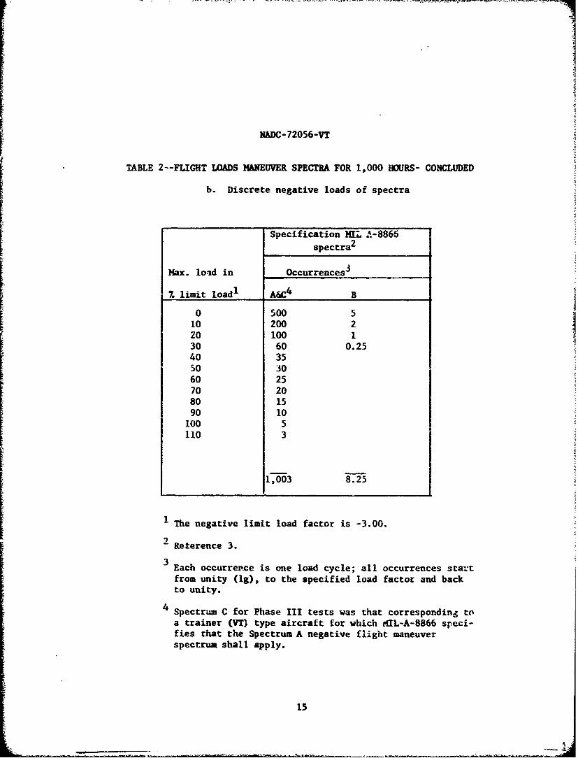
TABLE 2--FLIGHT LOADS MANEUVER SPECTRA FOR 1,000 HOURS- CONCLUDED
b. Discrete negative loads of spectra
Specification NIL A-8866spectra
2
Max. load in Occurrences 3
% limit load1 A&C4 B
0 500 510 200 220 100 130 60 0.2540 35so 3060 2570 2080 1590 10100 5110 3
1,003 8.25
1 The negative limit load factor is -3.00.
- Reterence 3.3
Each occurrence is one load cycle; all occurrences startfrom unity (lg), to the specified load factor and backto unity.
4 Spectrum C for Phase III tests was that corresponding toa trainer (VT) type aircraft for which MIL-A-8866 speci-fies that the Spectrum A negative flight maneuverspectrum shall apply.
15
- - ----- --- - -,. - -= -'--. • . ,t • ••-. -.# ... ,,-• • .i ,. . , • • •r
NADC- 72056-VT
TABLE 3--RESULTS OF STATIC FAILING-LOAD TESTS1 ' 2
Ranking Specimen Static Test performed Referenceorder No. strength, lb. at source
1 103 7,319 NBS 3 22 102 6,996 NBS 23 202 6,976 NBS 24 201 6,936 NBS 25 303 6,767 NBS 26 302 6,746 NBS 27 1 6,740 NBS 18 3-2-1 6,715 AVTD 59 3-2-2 6,700 AVID 5
10 1 6,615 AVID 411 2 6,615 AVTD 412 3-3-3 6,418 AVID -
13 3-3-1 6,218 AVID14 3-3-2 6,218 AV-D
LP= 93,979
1 Arithmeticmean = 97 9 fr 6,713#
in order to maintain consistence of loads throughout the entire pro-
grata for the various phases, an average failing load of 6,860 poundswas used as a basis for establishing loads for the specLra. Thiswas the average failing load determined at the start of the programbased on nine specimens. It was felt necessary to maintain thisbasis for spectrum test load determination, the change in mean bythe addition of other values later in the program being considerednot significant.
3 ,National Bureau of Standards, Washington, D.C.
16

KADC- 72056-VT
TABLE 4--FATIGUE LIVES IN EQUIVALENT FLIGHT HOURS 1 FOR LO-HIFIXMD-SEQMCE POSI• v WMDS FATIGUE TESTS, PHASE I
BUAER Specification MIL-A-8866
spectrum Spectrum A Spectrum B Spectrum C
Spectruablock 11 0x 11, 07, 14 07. 117. 07.size,hours M.S, MIS. M.S. MIS. M.S. M.S. M.S. M.S.
4859 3819 3299 1359 12,299 9,499 22,899 11,89920
50i9 4679 3359 1399 13.299 10,299 22,899 12,299
Av life 4939 4249 .3329 1379 12.799 9,899 22,899 12.099
4199 4019 4259 1499 1.-,959 6,659 33,899 16,61960
5579 4499 4439 1619 18.839. 7.019 35.133 17,579
Av life 4889 4259 4349 ,.559 17.399 6.39" 34,516 17.099
3297 3797 7099 3499 21,299 7,899 31,299 18,899100 1
3499 4299 7099 3899 22.5991 8.299 50.899 25,899
Av life 3398 4048 7099 3699 21,949 8,099 41,099 22,399
1 T.e two values at each test point are equivalent flight hours tofailure for two replications. Values are given to the closestnumber of hours actually sustained.
1~7

NADC-72056-VT
TABLE 5--FATIGUE LIVES IN EQUIVALENT FLIGHT HOURS FOR RANDOM-SEOUENCE FATIGUE TESI'r, 1A)SITIVE LOADS, PHASE II
BUAER Specification MIL-A-E866
Spectrum spectrum Spectrum A Spectrum B Spectrum Cblock
size, 1II1% 070 11% 011i% 0%1r O
hoursS:4. S. M.S. IM.S. M.S. M.S. M. S. M.S. %A.S.
S"t.568 1,917 3,238 1,776 7,587 S,587 27,28S 6,888
2• I5,346 2,121 3,265 1,825 8,531 20,899 27,S96 89888
Av life 4,957 2,019 3,251 1,80oo 8,059 9,743 27,5D2 7,888
2,665 1,888 3,108 2,170 7,7S1 7,936 21,381 9,861
60 4,424 2,458 3,414 2,260 28,393 8,261 26,790 12,048
Av life 3,544 2,173 3,261 2,215 13,087 8,098 24,085 11,13.1
2,396 1,934 3,004 2,191 11,888 6,883 37,265 !6,265
100 --,891 2,106 4,253 2,821 18,556 7,556 48,265 16,3S0
Av life 2,643 2,020 3,629 2 O,506 15,222 7,222_ 42,765 16,532
The two values at each test point are equivalent flight hours failure
for two replications. Values are given to the closest number of hours
actually sustained.
181

NADC-72056-.VT
ix 0 (D -4 C
-q -- -v-- I
ci c a) IT mC E &0 xS
0
a 0~ 0 0 04
0 . . 4 W o I z
(n 19

NADC-72056-VT
00 4
0 0 0 14 1
coc
Cd 0 `4 -4 -4 r- 4 4 4 4 -q -4 -4 -
F'rL LIZII
00
_ _ _ 4-J
4--i

NADC-?2036.-VT
100
54b44b
x~. 0, P- r444r MP 4
0 -0
z :-. M *0 &~4J 44 4 444,+ + A404-4 ~ 40 00 a aii 0 a0
0 -1 400 -- q- qu4Me ý tr
00 -,4 "4 m
V0 30 t ým t - oL
04 a
-401 00CC4Q9 t t- N 00 4 4 0 00 0~ Lm .4 ) 0 C 0 0 .0 0 NOo )Z > - OD goC1 0 40 co0 4 ý r 0 g G 0I
e4_ _ _VaO_0 _ _ __t_7_ _in_ _ __W_ _m_ __4 0C4ODaD&0000
21 C. V

[ NADC-72056-VT
'f4-4 0 c4 I" w 0D -A4
00 0 0 41 0 t. (
00 W W 4r oc,4C WV a. r.4 0S
04J W0 k. u-0 0CS " 4.40 14 * 000%u -.4 > .1 1 :-C4
00 w to00 0 S0A0 44- > 00 10 o
4 ..0. C W
00 4' u' 04D 0 u,~C-4
- 0 in C: c a
0 1 0'-0 0.:3.A n& tn o n w% -tO a. 0 e.
0-.4 410 C4-4 V4 ''4- CM Ni CM 040 4
,3 n4r4 CO r4J 0.4 r- 0- rca44 . _ _ _- 0".44. .
__4_ %4 Li 0)410E-44 04 w ca $
0 lev :)" A 0m-*0a- 0 w04
CC v C 0 0.-'3I-4C1)0 -4 41~~I-~ '' u .
w 0 41
I.-1x .4440 .. (4.40 .0 4
o 04) 0e A& l C % t0 0 toE- 0) " - -t f f. m0 u 00 U1 4
" 44 O r-.4 CnfN" t-o VO 410
.- 4-4 o'-4 4 4
0.44 0.4U 00 (P C8 c0a.
H. 0; W* 0 0 01>4C40$4ý. 0r r n 011 0 0 0.10 ~ ~ ~ ~ ~ ~ ~ -4- 00000c 4 0 m - 0 6
04-4 4 .... f 0 to %4VV*a141c u
-3A " 4141 InOý'') ' 0 4 13 "A le 24 % -0-.40 6i4! 0) b08 600) 0J 0 O00. 4461I'' 6 OW S 1
E-' 0.- ca m .) 000 24
41 04) c Id)dj~ 4J CO 0.caU ~ ~ ~ ~ ~ 3 U4 00-000c 4%o oo 4 L 0 Ee~ E C" 4 C
E- w~ CL4 1- AC 4 0E J0 0 -r40
to rn. a D4 A > 4 .~0O a 44e 1" w r 10
-4 4J Crl 4 44
22U >> 4Q

NADC- 72056-VT
> C-4~. CCr4 1'4NCdC#L ~ Oi.t-
im~ 4J n -i C,~~ C~'
0:z -, .14 -3 c- %D a, 41~ 'C
ca4- 44~~ c:r-ciI
w'''d CWeU En~c 0~- 0 -
cc 00 1~ i4~ J
00x -4 *.4) .4-a r,~~ tr C IJ t - 4a
0, -4 m ON-)mV3:
ZE-Y
I-J t j
-4- a' L'. I C-.t.CjLo Ca no %D 0 cn *7- I:L
000 11~ r.. - >
-4 -4
H -4
.- J ) -4 -4 '3 r '. - -n
Lr) -4 0 0- `4jcr 0 LA C\ C4 0 - ' -tIt-
C' _ _ -4 _ _
--
L23

- ~ ~ ~ ~ ~ ~ ~ m -- - -.--1---v.-- & . ~ --
NADC-72056-VT
TABLE 9--C0MPARISON OF AVERAGE FATIGUE LIVES IN EUIVALENT FLIGHTHOURS FOR POSITIVE LWADS ONLY AND FOR FULL SPECTRUM LOADS,11% MARGIN OF SAFETY
a. Fixed-sequence loading (bo-hi)
Spectrumblock MIL-A-8866 test spectrasize, Spectrum Spectrum Spectrumhours Type of loads A B C
20 Poo. only 3,3291 12,799 22,899Pos. & neg. 839 10,899 6,538
60 Pos. only 4,349 17,399 34,516Pos. & neg. 808 14,609 3,955
100 Pos. only 7,099 21,949 41,099Pos. & neg. 1, 547 6,749 15,443
b. Random-sequence loading
Spectrum
block MIL-A-8866 test qpectrasize, Spectrum Spectrum Spectrumhours Type bf loads A B C
2C Pos. only 3,2513 8,059 27,592Pos. & neg. 9972 14.581 4,084.
60 Pos. only 3,261 18,087 24,085Pos. & neg. 1,072 15,138 4,654
100 Pos. only 3,62= 15,222 42,765... Pos. & neg. 849 8,549 4,547
1 From Phase I tests, reference 4.
2From Phase III tests
3From Phase II tests, reference 8
24

NADC-72056-VT
-. 4 >o0m,0
0 00 to~ to n rq 0)ro r4 "4 C
f"~u 0 4>0- NNCQC V-4 3 QC9N0 o~ 0' *-4-C
-4 ~ ~ ~ ~ ~ ~ ~ ~ 0 V-4 -.4 -4A =-.4 4ý 4 4J14 -00 F-4 VS
>Z P4t 1
wl o 1404 M 0 W 0 Vt- v W t In N -4-4
mi.- 02 0 0
4 43 ul14 r4 .4
0~ L200 Ch 02 %C)a T)0 )I D hG )
'4-4 .0 000 0l4M0VM0-4W0WWt
i-O .4 w.)5- 0 0 0)-. t 4-.4.444
> S 14
-I0 In----- 0 202020z CIS4 I
4-4 1414 lV
00-.-a. 00 00 0000 00 00 0>.4-5 -i-44a a -4-4J-a L r''qf I
-~ 0 00202020
Q 4V41, 0020202020200 v4)4)4)4R ) : N 000 NOOC0O0000 00000>>
CL-trr-.4 1 40413NI o 1O- 4 -4 NI I IN IN 0 0 545-44545-4
m l )U)OKIn,. N a1 r o i0
00 IV V I ) I -r 0 1W t 4- 1 1 1 $ . 4U$
25

NADC- 7205r-VT
TABLE ll--FATIGUE LIVES IN MQUIVALEIT PJLIGHT HOURS' FOR EXTENDEDSTRESS-L•VL AND BIOCK-SIZZ RANGES, PHASE IV, POSITIVE
LOADS ONLY, LO-HI FIXED-SIQICB LWADING
Sp'ectrum A
__s___c__u_ Specification MIL-A-8866"Spectrum
Sblock Nominal L.L. stress,S~size,
hours 35 45 54
20 11,859 6,959 3,299213,839 9,539 3,359
_Av life "1_2,849 8,249 3,329
100 16,399 6,199 7,0992__._24,999 7,399 7,099
Av life 20,699 6,799 7,099
200 12,199 5,799 2,999
18,799 _6,.199 3,399AV life 15,499 __5,999 3,199
500 8,498 1,490 99721,493 1,499 1,499
."Av life 14,998 1,494 1,248
The two values at each test point are equival1nt flight
hours to failure for two replications. Values are givento the closest number of hours actuall sustained.
These data points are from Phase I (reference 4) ofthe program.
26

NADC-?2056-VT
0 0
a I- I I,1( 4 .i-
I
,o. Sr • 4
0 1
41
I ' I I 4
uu I
a-dinI
SI •t-4 ~ Va
0'W i,(.427

UMDC-72056-VT
Limit Load NM 7.33
cycle
Load
n 1 (base load)0 _ __ _ __
One loading Time orblock Cycles
Fixed-sequence, lo-hi, loading (reference 3)
* ne cycle; all loadlevels not shownwithin block
Loz-A
n = 1 (base load)-
One loading Time or --
block cyc es
Random-sequence loadin'-
Figure 2-- Comparisin of londing schematics f'r fixed-anc!random-sequence fatigue tests, MIIP-A-'i166 spectra,positive loads only
28

NADC-72056-VT
IW-Hi Order '
+ LoadOncyl
SUg baseload
Time or Cycles
One load block-Load
+ Woad
- Loadi
Figure 3-Schematic diagrams of fixed-sequence loading ordersfor positive and negative load fatigue teats
29

0 a r4
a'
414
toJ, 41 %W
4JdJA
.841I 41 0
0.4
C4 -
N
C44
V44
j 30

NADC- 72056-VT
07
-!4
I'I I, I -It.
31.~

NA.DC-720506-VT
jA
o %0 C'0c
'4j
u w 4j7 \ ~--K--0
. ~0'~-. C
'.0o0
-4 -g 0)
CC
4.-4
10(N ( th 4 .- X
CC CC" "UL
>* 0..5.44
(it~
CID C.
4,0
Wal 00 Ta~l iC
32 tZLn001U

NADe-72056-VT
vtI
0%
-4 -4
44 C)
CIS-
- 3.
.- 41
to0 -0 e
0 -0
414E
* V
*~ Alp~
44-
0 0 )
-lqV~ 001la
33

NADC- 72056-VT
400_
ou
u C%4 -4 0a
0to m r
EQ
C 0
V.4 w~0O -44.
r i
0 w0 0-004j-
a)4 1-
-4. fIO.J0 .4
-. 40> I"
Ci S4 ca cc4
> -a mJ ->, ., 01-
cc 00A.0
Mi >
V ) 4J -L4 4.4
00 v-4 ii
>0 >4 41a-A "4 0- m- -
(0 0 34 m
0 0 0I0C-
Ci Ci 0)>n 'T 4-i
.. 4 .,. 0142i COlAni aile ia1
4-i 4i *34

rNADC-72056-VT0
"II
EU E
X 4 !..-to0 tr0
C 0-
Cr)
13 00cc) 0*c)
a) 41 N 4M .twu-4o
0 -4-m
0 4d 0) 00u
to nO CD4 1I 0UTAfb Z~f~e1 C
35i 1-

NADC-73056-VT
rr
wo 4 .44
- 9"4
-~0 to tto V) V f
.94 Vwe 4
44 .;j 4A 4 .4I
fa4-IL$4$4$4 ci~a
ii0 no 10,V* 00 00 0Is 0 - -
Is J 0 A v
v-4#-4 -4 0%
so~ ~ ~ C1 00 4
I* V4 I C40
sinfoq zqS1I; ZuOiWAlnb- 4&swi~; o4 *IT
36

HADC- 72056-VT
24
20
16-
12
0
*i kýOQi
Curve:s cross plotLed from
Figure 10.
Figure 1l--Pictorial presentation of Spectrum A beam fatigue-life
data for extended stress-level and block-size ranges,
Phase IV, positive lo ds only, lo-hi fixed-sequence loading