Embed Size (px)
Citation preview
NAVAL
POSTGRADUATE SCHOOL
MONTEREY, CALIFORNIA
THESIS
MODEL OF THE US CENTCOM JOINT TARGETING ARCHITECTURE: DEVELOP TARGETS
by
David Germakian Derek Jaskowiak
June 2004
Thesis Advisor: John Osmundson Second Reader: William Kemple
Approved for public release; distribution is unlimited.

THIS PAGE INTENTIONALLY LEFT BLANK

REPORT DOCUMENTATION PAGE Form Approved OMB No. 0704-0188 Public reporting burden for this collection of information is estimated to average 1 hour per response, including the time for reviewing instruction, searching existing data sources, gathering and maintaining the data needed, and completing and reviewing the collection of information. Send comments regarding this burden estimate or any other aspect of this collection of information, including suggestions for reducing this burden, to Washington headquarters Services, Directorate for Information Operations and Reports, 1215 Jefferson Davis Highway, Suite 1204, Arlington, VA 22202-4302, and to the Office of Management and Budget, Paperwork Reduction Project (0704-0188) Washington DC 20503. 1. AGENCY USE ONLY (Leave blank)
2. REPORT DATE June 2004
3. REPORT TYPE AND DATES COVERED Master’s Thesis
4. TITLE AND SUBTITLE: Model of the Us Centcom Joint Targeting Architecture: Develop Targets 6. AUTHOR(S) David Germakian and Derek Jaskowiak
5. FUNDING NUMBERS
7. PERFORMING ORGANIZATION NAME(S) AND ADDRESS(ES) Naval Postgraduate School Monterey, CA 93943-5000
8. PERFORMING ORGANIZATION REPORT NUMBER
9. SPONSORING /MONITORING AGENCY NAME(S) AND ADDRESS(ES) N/A
10. SPONSORING/MONITORING AGENCY REPORT NUMBER
11. SUPPLEMENTARY NOTES The views expressed in this thesis are those of the author and do not reflect the official policy or position of the Department of Defense or the U.S. Government. 12a. DISTRIBUTION / AVAILABILITY STATEMENT Approved for public release; distribution is unlimited.
12b. DISTRIBUTION CODE
13. ABSTRACT (maximum 200 words)
This thesis was conducted in support of a larger research effort to improve US CENTCOM’s joint targeting architecture. The ultimate goal of this research project is to develop a working Extend model, which accurately describes CENTCOM’s targeting process, in order to assist the Joint Intelligence Interoperability Board (JIIB) in their JIIB Systems Baseline Assessment (JSBA) for fiscal year 2004, as well as for all subsequent JSBAs. This thesis explains the advantages of using a systems engineering approach to developing a process model, and ultimately an Extend model. It provides a brief description of the entire CENTCOM targeting cycle; however, it focuses on the “Develop Targets” activity. The two major products of this research effort are an accurate and detailed paper model using Microsoft Visio, and a baseline Extend model of the “Develop Targets” activity. The Extend model and its capabilities are described in full detail, and it will serve as the foundation from which the other activities in this targeting process will be modeled. Additionally, recommendations for future improvement of the model are explained.
15. NUMBER OF PAGES
115
14. SUBJECT TERMS Extend, Targeting Architecture, CENTCOM, JIIB, JSBA, Model, Joint, JFMCC, JFSOCC, JFACC, DJFLCC, JFC, JICCENT, Jaskowiak, Germakian
16. PRICE CODE
17. SECURITY CLASSIFICATION OF REPORT
Unclassified
18. SECURITY CLASSIFICATION OF THIS PAGE
Unclassified
19. SECURITY CLASSIFICATION OF ABSTRACT
Unclassified
20. LIMITATION OF ABSTRACT
UL
NSN 7540-01-280-5500 Standard Form 298 (Rev. 2-89) Prescribed by ANSI Std. 239-18
i

THIS PAGE INTENTIONALLY LEFT BLANK
ii
Approved for public release; distribution is unlimited.
MODEL OF THE US CENTCOM JOINT TARGETING ARCHITECTURE: DEVELOP TARGETS
David G. Germakian
Ensign, United States Navy Reserve B.A., Harvard University, 2003
Derek C. Jaskowiak
Ensign, United States Navy Reserve B.S., United States Naval Academy, 2003
Submitted in partial fulfillment of the requirements for the degree of
MASTER OF SCIENCE IN SYSTEMS TECHNOLOGY (JOINT COMMAND, CONTROL AND COMMUNICATIONS (C3))
from the
NAVAL POSTGRADUATE SCHOOL June 2004
Authors: David Germakian Derek Jaskowiak
Approved by: John Osmundson
Thesis Advisor
William Kemple Second Reader/Co-Advisor
Dan Boger Chairman, Department of Information Sciences
iii

THIS PAGE INTENTIONALLY LEFT BLANK
iv
ABSTRACT This thesis was conducted in support of a larger research effort to improve US
CENTCOM’s joint targeting architecture. The ultimate goal of this research project was
to develop a working Extend model, which accurately describes CENTCOM’s targeting
process. This model will assist the Joint Intelligence Interoperability Board (JIIB) in
their JIIB Systems Baseline Assessment (JSBA) for fiscal year 2004, as well as for all
subsequent JSBAs. This thesis explains the advantages of using a systems engineering
approach to developing a process model, and ultimately an Extend model. It provides a
brief description of the entire CENTCOM targeting cycle; however, it focuses on the
“Develop Targets” activity. The two major products of this research effort are an
accurate and detailed paper model using Microsoft Visio, and a baseline Extend model of
the “Develop Targets” activity. The Extend model and its capabilities are described in
full detail, and it will serve as the foundation from which the other activities in this
targeting process will be modeled. Additionally, recommendations for future
improvement of the model are explained.
v

THIS PAGE INTENTIONALLY LEFT BLANK
vi
TABLE OF CONTENTS
I. INTRODUCTION........................................................................................................1 A. THESIS STATEMENT...................................................................................2 B. THESIS APPROACH .....................................................................................2 C. THESIS RELEVANCE...................................................................................4 D. SUMMARY OF RESULTS ............................................................................5 E. ORGANIZATION OF THE REMAINDER OF THE THESIS..................6
II. JIIB................................................................................................................................7 A. HISTORY AND ORGANIZATION OF JIIB...............................................7 B. JSBA FY02 .......................................................................................................8 C. JSBA FY04 .....................................................................................................10 D. ROLE OF NPS IN JSBA FY04.....................................................................11
III. PROCESS MODELING ...........................................................................................13 A. HISTORY/BENEFITS ..................................................................................13 B. CENTCOM TARGETING ARCHITECTURE..........................................14 C. DODAF ...........................................................................................................15 D. FUNCTIONAL THREADS ..........................................................................15
1. Extend .................................................................................................21
IV. CENTCOM TARGETING PROCESS....................................................................23 A. OVERALL TARGETING ARCHITECTURE...........................................23 B. DEVELOP TARGETS ACTIVITY .............................................................25
1. Provide Targeting Support ...............................................................26 a. Initial Target Selection Process..............................................26 b. Acquire Additional Target Intel .............................................26 c. Disseminate Appropriate Target Information .......................27
2. Receive and Integrate Candidate Targets .......................................28 a. DJFLCC CTL Development ...................................................28 b. JFACC CTL ............................................................................29 c. JFC CTL..................................................................................29
3. Prioritize and Staff Candidate Targets............................................29 a. DJFLCC Approved and Prioritized CTL and Daily
Diverts......................................................................................30 b. JFACC Prioritized and Staffed CTL......................................30 c. JFC Prioritized and Staffed CTL ..........................................30
C. ORGANIZATIONS WITHIN DEVELOP TARGETS..............................31 1. ACE .....................................................................................................31 2. BCD .....................................................................................................32 3. CID Targets ........................................................................................32 4. COID Targets .....................................................................................32 5. DCCC..................................................................................................32
vii6. DJFLCC..............................................................................................33
7. DOCC..................................................................................................33 8. F2C2 ....................................................................................................34 9. JFACC ................................................................................................34 10. JFC ......................................................................................................34 11. JFMCC................................................................................................35 12. JFSOCC..............................................................................................35 13. JGAT Cell ...........................................................................................35 14. JICCENT............................................................................................35 15. JICCENT (Rear)................................................................................36 16. JICCENT DARS ................................................................................36 17. JICCENT Targets..............................................................................36 18. JICCENT WMD Cell ........................................................................37 19. JOC......................................................................................................37 20. JTCB ...................................................................................................37 21. MAW...................................................................................................38 22. NIMA ..................................................................................................38 23. NMJIC Targeting Cell.......................................................................38 24. S&R Sensors .......................................................................................38 25. SOF......................................................................................................39 26. WOC....................................................................................................39
D. SYSTEMS UTILIZED DURING DEVELOP TARGETS.........................39 1. AFATDS..............................................................................................39 2. JDISS...................................................................................................40 3. ASAS ...................................................................................................41 4. JCMT ..................................................................................................41 5. GCCS ..................................................................................................42 6. IPA.......................................................................................................42 7. JMCIS .................................................................................................43 8. S&R Systems ......................................................................................44 9. TBMCS ...............................................................................................44 10. JTT ......................................................................................................44 11. RRS......................................................................................................45 12. GALE ..................................................................................................45 13. TARCHECK ......................................................................................46
E. COMMUNICATION METHODS ...............................................................46 1. DMS.....................................................................................................46 2. GBS......................................................................................................47 3. JWICS.................................................................................................48 4. SIPRNET ............................................................................................48 5. Courier ................................................................................................48 6. Voice ....................................................................................................49
V. EXTEND MODEL OF DEVELOP TARGETS......................................................51 A. MODEL DEVELOPMENT ..........................................................................51
1. Model Architecture............................................................................52 2. Cloning Items .....................................................................................55
viii
3. Standardized Model Procedures ......................................................55 4. Model Database Inputs......................................................................56
B. EXTEND BLOCKS .......................................................................................60 1. Activity Delay .....................................................................................61 2. Batch....................................................................................................61 3. Batch (10)............................................................................................61 4. Catch ...................................................................................................62 5. DB Lookup..........................................................................................62 6. Exit ......................................................................................................62 7. Get Attribute ......................................................................................63 8. Input Random Number .....................................................................63 9. Program ..............................................................................................63 10. Queue FIFO........................................................................................63 11. Select DE Output................................................................................63 12. Select DE Output (5)..........................................................................64 13. Set Attribute .......................................................................................64 14. Throw..................................................................................................64 15. Unbatch...............................................................................................64 16. Unbatch (Variable) ............................................................................65
C. MODULAR BLOCKS...................................................................................65 1. Communications Delays ....................................................................66
a. Network Delay .........................................................................66 b. Courier Delay ..........................................................................68 c. Voice Delay..............................................................................69
2. Timer Send Block...............................................................................71 3. Miscellaneous H-blocks .....................................................................72
a. Timer........................................................................................72 b. DARS .......................................................................................73
D. DATA DICTIONARY...................................................................................74 1. Attributes ............................................................................................74 2. Modular Blocks ..................................................................................75 3. Names of Catch Blocks ......................................................................76
VI. RESULTS AND CONCLUSIONS ...........................................................................79 A. IMPORTANCE OF EXTEND MODEL .....................................................79 B. EXTEND MODEL RESULTS......................................................................80 C. MODEL IMPROVEMENTS........................................................................85
1. Increase Accuracy..............................................................................85 2. Alternate Metrics ...............................................................................86 3. Enhancing the Timer Block to Process Multiple Runs...................87
LIST OF REFERENCES......................................................................................................89
INITIAL DISTRIBUTION LIST .........................................................................................93
ix

THIS PAGE INTENTIONALLY LEFT BLANK
x
LIST OF FIGURES
Figure 1. Functional Threads...........................................................................................16 Figure 2. Information Exchange Requirement Template Model ....................................17 Figure 3. Interoperability Analysis Flow ........................................................................20 Figure 4. US CENTCOM Joint Targeting Process .........................................................23 Figure 5. Develop Targets Level 1..................................................................................53 Figure 6. Develop Targets Level 2..................................................................................53 Figure 7. Develop Targets – Information Processing (1.3) Level 3................................54 Figure 8. Extend Blocks 1 ...............................................................................................62 Figure 9. Extend Blocks 2 ...............................................................................................64 Figure 10. Extend Blocks 3 ...............................................................................................65 Figure 11. Modular H-blocks ............................................................................................66 Figure 12. Network Delay H-blocks .................................................................................67 Figure 13. Extend Blocks Inside Net H-block ..................................................................68 Figure 14. Courier Delay H-block.....................................................................................68 Figure 15. Extend Blocks Within Courier H-Block ..........................................................69 Figure 16. Voice Delay H-blocks......................................................................................70 Figure 17. Extend Blocks Within Voice H-block .............................................................70 Figure 18. Extend Blocks Within Timer Send H-block ....................................................72 Figure 19. Extend Blocks Within Timer H-block .............................................................72 Figure 20. Extend Blocks Within DARS H-block ............................................................74 Figure 21. Extend File Output Block’s Data Table Containing Model Run Time ...........81 Figure 22. Exponential Distribution..................................................................................82
xi

THIS PAGE INTENTIONALLY LEFT BLANK
xii
LIST OF TABLES
Table 1. Database for Communication Delay Distributions ..........................................57 Table 2. Database for Activity Delay Distributions.......................................................58 Table 3. Sample Timer Output.......................................................................................73 Table 4. Varying Bandwidth Extend Model Run Times ...............................................83
xiii

THIS PAGE INTENTIONALLY LEFT BLANK
xiv
ACRONYM LIST
ABCS Army Battle Command System ACE Analysis and Control Element ADOCS Advanced Deep Operations Coordination System AFATDS Advanced Field Artillery Tactical Data System AOC Air Operations Center ASAS-L All Source Analysis System Light ASAS-RM All Source Analysis System Remote Workstation ATO Air Tasking Order BCD Battlefield Coordination Detachment C4ISR Command, Control, Communications, Computer, Intelligence,
Surveillance, and Reconnaissance CDL Collateral Damage List CENTCOM Central Command CID Combat Intelligence Division CMA Collection Management Authority COE Common Operating Environment COID Combat Operations Intelligence Division CONOPS Concept of Operations CONUS Continental United States COTS Commercial off the Shelf CTL Candidate Target List DARS Daily Aerial Reconnaissance and Surveillance DB Database DBS Data Broadcast System DCAP Data Collection and Analysis Plan DCCC Defense Collection Coordination Center DIICOE Defense Information Infrastructure Common Operating Environment DIN Defense Intelligence Network DISA Defense Information Systems Agency DJFLCC Deputy Joint Forces Land Component Commander DMS Defense Message System DOCC Deep Operations Coordination Cell DOD Department of Defense DODAF Department of Defense Architectural Framework F2C2 Friendly Forces Coordination Center FDDI Fiber Distributed Data Interface FIFO First In First Out FSCL Fire Support Coordination Line GALE Generic Area Limitation Environment GBS Global Broadcast System GCCS-A Global Command and Control System - Army GCCS-I3 Global Command and Control System - Integrated Imagery and
Intelligence
xv
GCCS-M Global Command and Control System - Maritime HPSCI House Permanent Select Committee on Intelligence HUMINT Human Intelligence IER Information Exchange Requirement IMINT Imagery Intelligence IOS Intelligence Operations Server IPA Image Product Achieve IS Information System ISR Intelligence, Surveillance, and Reconnaissance JBC Joint Battle Center JCMT Joint Collection Management Tools JDISS Joint Deployable Intelligence Support System JFACC Joint Forces Air Component Commander JFC Joint Forces Command JFMCC Joint Forces Maritime Component Commander JFSOCC Joint Forces Special Operations Component Commander JGAT Joint Guidance, Apportionment, and Targeting JICCENT Joint Intelligence Center CENTCOM JIIB Joint Intelligence Interoperability Board JIIWG Joint Intelligence Interoperability Working Group JITC Joint Interoperability Test Center JMCIS Joint Maritime Command Information System JOC Joint Operations Center JQRR Joint Quarterly Readiness Review JSBA JIIB Systems Baseline Assessment JTCB Joint Target Coordination Board JTF Joint Task Force JTL Joint Target List JTT Joint Targeting Toolbox JWICS Joint Worldwide Intelligence Communications System MASINT Measurement and Signature Intelligence MAW Marine Aircraft Wing MIDB Modern Integrated Database MP&BF Maps, Plots, and Briefing Folders NCA National Command Authority NGA National Geospacial Intelligence Agency NIMA National Imagery and Mapping Agency NITF News Industry Text Format NMJIC National Military Joint Intelligence Center NPS Naval Postgraduate School OIF Operation Iraqi Freedom OPLAN Operation Plan OPORD Operation Order FRAGO Fragmentary Order PM Program Manager
xvi
PSYOP Psychological Operations ROE Rules of Engagement RSS Remote Replication System S&R Surveillance and Reconnaissance SCI Sensitive Compartmentalized Information SIGINT Signals Intelligence SIPRNET Secret Internet Protocol Routing Network SJA Staff Judge Advocate SOF Special Operations Forces SOR System of Record TACLAN Tactical Local Area Network TARCHECK Target Check TBMCS Theater Battle Management Corps System TIFF Tagged Image File Format UML Unified Modeling Language VTCS Video Tele-conference WMD Weapons of Mass Destruction WOC Wing Operations Center
xvii

THIS PAGE INTENTIONALLY LEFT BLANK
xviii

ACKNOWLEDGMENTS
We would like to extend our appreciation to Professor Rich Kimmel and the NPS
JIIB team for involving us so heavily in this project, and arranging for the opportunity to
present our work at the Joint Battle Center in Suffolk, VA. We also offer a special thanks
to Dr. John Osmundson and Dr. William Kemple for their expertise in scoping, guiding
and critically reviewing our work throughout this research effort. Elizabeth Jaskowiak
proved to be a great help in revising this document. Finally, we sincerely appreciate our
classmates in CC4103 who assisted us in getting this project off the ground by beginning
to develop the paper model.
xix

THIS PAGE INTENTIONALLY LEFT BLANK
xx
I. INTRODUCTION
This thesis was conducted in support of a much larger research effort to improve
US CENTCOM’s joint targeting architecture. The ultimate goal of this research project
is to develop a working Extend model, which accurately describes CENTCOM’s
targeting process, in order to assist the Joint Intelligence Interoperability Board (JIIB) in
their JIIB Systems Baseline Assessment (JSBA) for fiscal year 2004, as well as for all
subsequent JSBAs. This project was initiated to address interoperability problems during
Operation Iraqi Freedom (OIF), which are highlighted in CENTCOM’s joint quarterly
readiness review (JQRR). However, in order to determine potential solutions and process
improvement methods for CENTCOM in the form of both alternate architectural
structures and cost-to-benefit analyses, it was essential that the process, including all
information exchanges and systems, be fully understood.
The necessary understanding of CENTCOM’s joint targeting process was
achieved by studying a set of three documents, US CENTCOM Objective Architecture
Concerning Targeting, Volume I – Volume III. These documents were created in 1997.
They are quite outdated, and do a poor job of describing the architecture by leaving many
gaps and holes in the process. However, due to the fact that these are the most current
documents that exist, they are what had to be used to begin this effort. This substantiates
the need for a current, accurate and well-described model. The approach, as will be
discussed later, will use these 1997 documents as a starting point. Through an iterative
process of talking with operators actually involved in the process, the model will be
refined to better represent the current architecture being employed.
The overall targeting cycle includes the following six primary activities:
• Establish Guidance and Assign Resources
• Develop Targets
• Prioritize Targets
• Publish ATO
• Manage Targets
• Conduct Combat Assessment
1

This thesis will provide a brief description of the entire cycle; however, it will
focus on the “Develop Targets” activity. The two major products of this research effort
are an accurate and detailed paper model using Microsoft Visio, and a working extend
model. Both of these models can be found at the Internet site
<http://library.nps.navy.mil/uhtbin/hyperion/04Jun_Germakian>. The Visio paper model
(400 KB) is listed as “Develop Targets Paper Model in Visio.” The Extend model is
available at this site in two forms. To view and run the Extend model in Extend, Extend
version 6.0 or higher is required. This is a 10MB file and is listed as “Develop Targets
Extend Model.” If Extend is unavailable, then the model can be viewed in Power Point
(400 KB). Power Point serves merely as a visual representation of the Extend model’s
architecture, and not as working simulation. The link to this file is “CENTCOM
Targeting Architecture develop targets extend model.”
This written document will provide the reader an understanding of the project’s
importance, what process modeling is and why it is useful, what the Extend simulation
and modeling tool is and why that is useful. It will also provide a detailed understanding
of what is transpiring during the “Develop Targets” activity, and ultimately a summary of
results and conclusions leading to potential methods for model and process improvement.
A. THESIS STATEMENT
The goal of this thesis is to support a research effort being conducted at the Naval
Postgraduate School to develop a working Extend model of CENTCOM’s joint targeting
architecture. After research and analysis, an accurate paper model and working Extend
model were created for the “Develop Targets” activity. The primary measure of
effectiveness was time to complete each activity.
B. THESIS APPROACH The approach taken to develop a working Extend model of the “Develop Targets”
activity was as follows. Initially, a thorough study of the entire targeting architecture was
conducted using information from the document set: US CENTCOM Objective
Architecture Concerning Targeting, Volume I – Volume III. Through a careful reading of
2
the process description, graphics and charts, and information exchanges, a paper model
was created in Microsoft Visio. This paper model contained numerous holes, or gaps in
the flow of information, and multiple iterations were required in order to fill these in to
the best of our ability. Once complete, the Visio paper model drove the creation of the
Extend model.
We attended an intensive course in modeling and simulation using Extend, and
used this tool to create a working model of the “Develop Targets” activity. Again, this
involved an iterative process of building many paper models and “throwaway” Extend
prototype models before generating a final version in Extend.
In parallel, the other major activities in the targeting architecture were being
modeled using the same process. Bi-monthly group meetings were conducted to assure
the overall model would link together properly. These meetings were important to ensure
that this model would address the issues and concerns that the JIIB had about the joint
targeting architecture. In order to do this properly, it was necessary to make sure the
model was analyzing the most effective measures and contained the appropriate level of
detail.
The “Develop Targets” activity was the first completed, and all results discussed
in this thesis pertain strictly to this activity. The capabilities of the “Develop Targets”
model were briefed at the Joint Battle Center (JBC) located in Suffolk, VA on May 17,
2004. The model received many positive reviews and demonstrated NPS student
involvement on the project. However, it is important to note that the JIIB project will not
stop here. In fact, once all six activities of the Extend model are combined and
functioning properly, there will still be a significant amount of work required. Recall that
this model is based off of an outdated document, with the gaps filled in to the best of our
ability. The primary purpose of this initial, baseline model is to make the JIIB aware of
the tools that exist to help them refine the targeting architecture. The baseline model will
provide a taste of how effectively this process can be altered and analyzed once a detailed
and accurate model is developed. The next step would be to update the model by talking
3
to the operators. This will allow the intricacies of the current process to be understood.
From this information, the baseline Extend model can be further refined to include these
exact details.
C. THESIS RELEVANCE The development of an accurate paper and Extend model of the joint targeting
process would be of enormous benefit because currently no accurate and easily
understood documentation exists. The accompanying written material will allow for
further understanding of the models by those needing the information. The relevance of
this research effort will become more apparent as one becomes more familiar with the
power of process modeling and Extend, which is described later in this document.
The Goldwater-Nichols Act of 1986 has driven the DoD to operate as a joint force
(NDU). However, the realization of a smooth and effective joint force requires an
ongoing effort as described in Joint Vision 2020. The joint force has become and will
remain the key to operational success long into the future because of its flexibility and
responsiveness (Joint Vision 2). The effectiveness of joint warfare is undeniable, which
is why we have seen joint efforts in the past three major conflicts.
…the employment of the capabilities of the Total Force (active, reserve, guard, and civilian members) increases the options for the commander and complicates the choices of our opponents. To build the most effective force for 2020, we must be fully joint: intellectually, operationally, organizationally, doctrinally, and technically (Joint Vision 2).
The movement toward a joint force has become a reality, but in order to do so
effectively, it is important to have sound doctrine. A second key aspect needed to
optimize joint warfighting capabilities is to ensure interoperability.
Interoperability is the foundation of effective joint, multinational, and interagency operations. The joint force has made significant progress toward achieving an optimum level of interoperability, but there must be a concerted effort toward continued improvement. Such improvements will include the refinement of joint doctrine as well as further development of common technologies and processes. (Joint Vision 15)
4
Due to the three recent major conflicts occurring within US CENTCOM’s area of
responsibility, it is clear why they have stated a need to refine their joint targeting
process. However, the implications of the development and documentation of such a
process will be of use to nearly all US Unified Commands, as they will inevitably be
tasked with an increasing number of joint operations requiring a targeting process.
Furthermore, the effort associated with taking the detailed paper model and
description to the next level by building a working Extend model will be of incredible
value to US CENTCOM and the JIIB. It will allow them to understand exactly how their
process functions so that they can determine the best method for improvement; whether it
be by restructuring the process, or investing in system upgrades to solve interoperability
issues. Adjustments and changes to the process can be made using the model, and the
effects can be analyzed. This will, in turn, result in the most efficient and cost-effective
means of determining how to improve their process in the future. For example, rather
than just thinking that by investing millions of dollars to increase the bandwidth of a
certain system they can reduce the length of the targeting cycle dramatically, only to find
out later that it actually had no significant effect, they could easily test this scenario in the
model and observe the results. As long as the model is updated it will always be useful
as a process analysis tool.
.
D. SUMMARY OF RESULTS The creation of this model was of great benefit to the NPS JIIB team by serving as
a foundation from which the other activities could be modeled in a similar fashion. Many
of the kinks with Extend were worked out, which will make the future modeling effort for
the other activities smoother.
Also, this model demonstrates its ability to track one of the key metrics, time to
complete tasks, throughout the process. The baseline Extend model of “Develop
Targets” generates the time it takes for information to flow to different parts of the
model. Ultimately, this demonstrates the capabilities that exist for a model of this sort.
Once additional research is conducted to produce more accurate parameters within the
model, the practical utility of the model will be evident.
5
E. ORGANIZATION OF THE REMAINDER OF THE THESIS
Chapter II: JIIB
• Discusses the history, purpose, and organization of the JIIB
• Specifies the objective required of the Naval Postgraduate school in the JSBA FY 04
Chapter III: Process Modeling
• Lends insight into the benefits of process modeling and current lack of process modeling efforts with respect to C4ISR architectures
• Explains the value of using a systems engineering approach to develop a process model
• Discusses the advantages of evolving the paper model into a computer simulation model using the Extend environment
Chapter IV: CENTCOM Targeting Process
• Provides a brief overview of CENTCOM’s joint targeting process
• Details the specifics of the “Develop Targets” activity
• Describes the organizations, systems, and communication methods involved throughout this activity
Chapter V: Extend Model of Develop Targets
• Demonstrates the method through which the Extend model was constructed
• Explains the overall model architecture
• Provides a more detailed look at how functions are performed in the model
• Discusses how we used the Extend software to create this model
Chapter VI: Results and Conclusions
• Explains the usefulness of the baseline “Develop Targets” model
• Discusses the results generated from varying bandwidth in the model
• Highlights the importance of further research to make communication and process delay parameters as accurate as possible
• Mentions the future capability of the model to track alternate metrics
6
II. JIIB
The Joint Intelligence Interoperability Board (JIIB) is charted to promote
intelligence systems interoperability to enhance intelligence support of the warfighter
(Joint Intelligence).
A. HISTORY AND ORGANIZATION OF JIIB The JIIB enforcement of interoperability is based solely on the language in the
FY98 Authorization Bill of the House Permanent Select Committee on Intelligence
(HPSCI). This bill directed the creation of a C4I interoperability management focal
point. The JIIB charter recognizes the Joint C4I Battle Center (JBC) as an advisory
member to perform system interoperability and functional assessment of identified
intelligence systems (JSBA FY04 Project).
The JIIB is chaired by the Deputy Director for Intelligence Assessments,
Doctrine, Requirements and Capabilities (J2P). It consists of planner-level
representatives from the Services, advisors from various agencies, and the Program
Managers (PMs) of Joint and Service related intelligence systems. The board meets
quarterly to provide a venue for direct PM-to-PM liaison and convenes the Joint
Intelligence Interoperability Working Group (JIIWG) as required to address specific JIIB
tasks (JSBA FY04 Project).
To satisfy its task of identifying interoperability shortfalls among Service and
Joint systems, the JIIB Systems Baseline Assessment (JSBA) was developed. The first
JSBA was published in 1999 to provide a baseline to compare future intelligence
interoperability assessments. A few years later, the JIIB requested that the JBC
determine the status of interoperability and document changes since the previous baseline
in 1999. The JBC responded with the JSBA FY02. The results of JSBA FY02 were
delivered to the JIIB in March 2003. During that same period of time, the JIIB decided to
conduct a JSBA every two years. Currently, JSBA FY04 is being assembled (Joint
Intelligence).
7
B. JSBA FY02
The JIIB requested the JBC conduct a baseline assessment of the current Joint and
Service intelligence systems to determine the existing status of interoperability and
document changes since the baseline set in 1999. In response, the JBC executed the
JSBA FY02. The JSBA FY02 assessed the technical interoperability of current Joint and
Service intelligence systems of record (SOR) to exchange critical intelligence
information in a Joint Task Force (JTF) environment. It successfully appraised
interoperability progress made by the JIIB SOR since the JBC initial JSBA in 1998 and
1999. It also extended the assessment’s scope to include Sensitive Compartmented
Information (SCI) level intelligence systems and Multi-Level Security (MLS) systems
(Joint Intelligence)
The JSBA FY02 project assessed the following Joint and Service C4I systems as
directed by the JIIB:
Service Systems (U.S. Secret level)
• Navy Global Command and Control System-Maritime (GCCS-M)
• Army All Source Analysis System Remote Work Station (ASAS RWS)
• Army All Source Analysis System-Light (ASAS-L)
• Air Force Theater Battle Management Core System (TBMCS)
• Marine Corps Intelligence Operations Server (IOS)
• Global Command and Control System-Army (GCCS-A)
• Joint Systems (U.S. Secret level)
• Global Command and Control System-Integrated Imagery and Intelligence (GCCS-I3)
• Special Operations Forces Tactical Local Area Network (TACLAN)
• Joint Deployable Intelligence Support System (JDISS)
• Advanced Deep Operations Coordination System (ADOCS)
• Joint Systems (U.S. Top Secret/SCI level)
• Global Command and Control System-Integrated Imagery and Intelligence (SCI GCCS-I3)
• Joint Deployable Intelligence Support System (JDISS-UNIX) (Joint Intelligence)
8
These systems are considered vital for intelligence exchange at the JTF level. The
systems transfer e-mail, message traffic, overlays, imagery, and other standard
intelligence products used to conduct intelligence support operations (Joint Intelligence).
The major finding of the JSBA FY02 was a large improvement in technical
interoperability between intelligence systems since the 1999 JSBA project. This is
largely due to the creation of a common set of hardware and software for the Navy, Air
Force, Marines, and the Joint Force Headquarters. This software and hardware allowed
GCCS-I3, JDISS, GCCS-M, IOS, and TBMCS to transfer information almost seamlessly.
It is important to note that while the potential for interoperability has been demonstrated,
most of the successes cannot currently be easily duplicated during field operations (Joint
Intelligence).
9
Despite the interoperability advances, there remain limitations. The first
limitation to interoperability is a critical shortage of system experts who are
knowledgeable of both required intelligence functions and the complex technical
configuration of the different intelligence systems needed for the Joint environment.
Current intelligence training and system documentation tends to be oriented heavily
towards Service applications and lacks sufficient focus on Joint operations. A second
inadequacy is the divergent Army doctrine identified during the 1999 JSBA. While other
Service and Joint systems have tended to consolidate functions on common suites of
hardware and Defense Information Infrastructure Common Operating Environment (DII
COE) compliant software, the Army battle command systems (ABCS) concept currently
utilizes eight separate systems. The final considerable interoperability shortcoming is the
significant expansion of interoperability requirements. Combatant Commands have
identified several new intelligence interoperability requirements since the 1999
assessment. The most noteworthy of these requirements are the need to exchange
information across security domains, the replication of key data sharing, and targeting
functions between the Joint headquarters and components. Additionally, there exists the
continued problem of dealing with mobile targets and unconventional forces, which may
require major revisions to the Modernized Integrated Database (MIDB), and other army
databases to support the war on terror. The greatest future challenge identified by the
JSBA FY02

will be building a consensus between the Combatant Commanders and the Services
regarding the selection and prioritization of technological improvements to the SORs
(Joint Intelligence).
C. JSBA FY04 While still maintaining its goal to identify interoperability shortfalls among
Service and Joint systems, the JSBA FY04 has a different focus than the previous JSBAs.
It will focus on two CENTCOM initiated Joint Quarterly Readiness Reviews (JQRRs).
The first identifies several interoperability deficiencies between systems that comprise
the joint targeting architecture. The second highlights interoperability deficiencies in the
Intelligence, Surveillance, and Reconnaissance (ISR) collection management applications
across the joint spectrum. Two other areas of focus are potential interoperability
problems introduced by fielding multiple versions of the Global Command and Control
System (GCCS) and fielding multiple versions of the MIDB (JSBA FY04 Project).
JSBA FY04 will be worked on by several different organizations. Both the
Meyer Institute of Systems Engineering and the Information Sciences (IS) Department
from the Naval Postgraduate School (NPS) are participating. Also contributing to the
JSAB FY04 is Joint Forces Command (JFC), Joint Battle Center (JBC), and Joint
Interoperability Test Center (JITC) (JSBA FY04 Project).
The JSBA FY04 will be conducted in six phases over FY04-05.
Phase 1: Operational Context
Phase 2: Modeling & Simulation
Phase 3: Technical Assessment
Phase 4: Operational Field Study
Phase 5: Analysis and Reporting
Phase 6: Planning for JSBA 06 (JSBA FY04 Project)
10
The first phase, Operational Context, defines the context, systems capabilities,
documentations requirements, data collection and analysis plan (DCAP), scope,
scenarios, and field studies. The next phase, Modeling and Simulation, will create and
populate the necessary process, technical, and data models needed to characterize system
behavior, based on the results from the first phase. Technical Assessment is the third
phase. This phase will be conducted at the JBC. The program offices will assist the JIIB
in conducting a controlled assessment of the JIIB systems. This phase also includes a
series of functional tasks in a simulated JTF communications environment to address the
specific technical interoperability issues identified in phases one and two (JSBA FY04
Project)
Phase four, Operational Field Test/Operational Field Study, will use pre-existing
joint exercises to validate the findings from previous phases. The primary exercise will
be Exercise Unified Endeavor 2004. The fifth phase, Analysis and Reporting, will
produce a “Quick look” report, which will combine the interim reports completed at the
end of each phase. The final report will be delivered to the JIIB in March of 2005. The
final phase, planning, will take place in Apr-May 05. A JIIWG will be convened to
produce a plan for JSBA FY06 (JSBA FY04 Project).
D. ROLE OF NPS IN JSBA FY04
The Naval Postgraduate School will use a systems engineering approach that will
elucidate key joint intelligence issues, examine and trade alternate approaches, and
provide a direct connection to select, on-going joint intelligence processes and activities
in order to satisfy the JIIB’s requirements (JSBA FY04 Project). The JQRRs highlight
interoperability deficiencies in ISR collection management applications across the joint
spectrum and deficiencies between systems that comprise the joint targeting architecture.
Both targeting and collection management processes will be the focus of the NPS
modeling effort for JSBA 04. However, targeting is the initial operational process to be
researched and modeled (JIIB Activity Report). The task of researching and modeling the
CENTCOM targeting architecture was broken down into smaller sections. This thesis is
responsible for successfully researching and modeling one of these segments. NPS will
develop process models in an Extend environment to support an assessment of the 11

targeting architecture and technical interoperability of current Joint and Service
intelligence SOR to exchange critical intelligence information in a JTF environment (JIIB
Activity Report).
12
III. PROCESS MODELING
Current documents that exist for a vast majority of DoD systems, and information
systems in particular, are deficient in describing their processes in a manner that is easily
understood, or dissected. Furthermore, with no standard architecture for developing and
describing C4ISR systems, each Military Service, major command, and Defense Agency
resorts to using different methodologies. This has resulted in system architectures that
cannot be readily shared and understood, leading to problems with defining information
exchanges and even joint interoperability issues (All-DoD 1).
A. HISTORY/BENEFITS Process modeling can be thought of as a systems engineering approach to
understanding the flow of information through a system or process. An advantage of
using the Systems Engineering Process Modeling approach has to do with its “ability to
analyze complex systems problems in terms of fundamental parameters, formulate
alternate architectural solutions, perform trade-off analyses of the alternate solutions, and
select a best solution based on a reasonable set of selection criteria” (Osmundson 68).
This trade study methodology has proven to be extremely effective in the aerospace
industry, resulting in more informed acquisition decisions (Osmundson 68). However,
“application of similar systems engineering principles has been lacking in the area of
information systems…especially in the design and analysis of complex, time-critical
networked, distributed information systems, including military command, control,
communications, computer, intelligence, surveillance, and reconnaissance (C4ISR)
systems” (Osmundson 68).
The development of detailed process models has several benefits:
• Results in the creation of current and accurate documentation.
• Saves resources (time, money, manpower, etc.) during architecture
development and assessments.
• Reduces risk by ability to model changes before capital investment.
13
• Provides more comprehensive analyses.
• Permits analysis of overall system and individual processes with minimal
expense and time.
B. CENTCOM TARGETING ARCHITECTURE The specific process that will be addressed throughout this paper is US Central
Command’s Targeting Architecture. U.S. Central Command’s Objective Architecture
Concerning Targeting is a document from 1997, which details the organizations,
procedures, information and systems involved in the targeting process. But the
architecture that was employed to describe this process is not easily translated into an
accurate paper model due to information gaps. Also, important modeling concerns, such
as timing, are rarely mentioned. If a standard UML type architecture had been used to
describe the targeting process, the paper model would have been much easier to
complete.
A common argument for why these architectures are rarely produced for
information systems stems from the belief that communication systems infrastructures
would be far too expensive to change. This point is refuted by noting the importance of
“the systems engineering precept that it is useful to know what an unconstrained solution
to a problem is as well as the potential trades in performance and cost from constrained
and unconstrained solutions” (Osmundson 69). For example, a process model designed
to represent CENTCOM’s Targeting Architecture could be extremely useful in
highlighting areas that hold up or cause a backlog in the flow of information. Once these
areas are revealed, further data from simulations and cost analysis could lead to decisions
on whether or not to change processes and/or invest in more advanced systems that can
process and distribute the information more quickly. A common misconception when it
comes to improving military C4ISR systems is to simply increase bandwidth. However,
this solution is costly and has the potential to overload system operators with unnecessary
information. Clearly, the development of an accurate process model would be extremely
useful in order to optimize the system being analyzed.
14
C. DODAF
The DoD is attempting to improve the way its systems are described through the
implementation of Department of Defense Architectural Framework (DODAF)
documents. Information systems are designed to get the correct information to the
intended recipient both accurately and within a specified timeline. Current documents
that describe most information system architectures make this aspect of process modeling
very difficult. However, the DODAF system is based on the unified modeling language
(UML) (All-DoD 17), which “utilizes use case and sequence diagrams among other
constructs to help determine information producers and recipients” (Osmundson 70).
From these standardized documents across commands, services, and agencies, the IERs
can be translated into a thread-based representation, and subsequently into a paper model.
In the case of modeling CENTCOM’s Targeting Architecture, these convenient DODAF
documents are non-existent. This means that a large effort must ensue just to translate
the given architecture into a thread-based representation and eventually a paper model. A
push is being made to require compliance in creating DODAF documents for each DoD
system or process, but currently no mandate exists (All-DoD 17).
D. FUNCTIONAL THREADS The functional thread sequence, through which an iterative process will
eventually become a detailed paper model, shares many similarities with the UML
sequence mentioned previously. A thread-based representation of a process not only
accurately defines the IERs, but also provides insight into system time behavior, which
becomes a key parameter in analyzing the performance of distributed, time-sensitive
tasks. An example of a functional thread diagram is shown in Figure 1 (Kimmel 4).
15
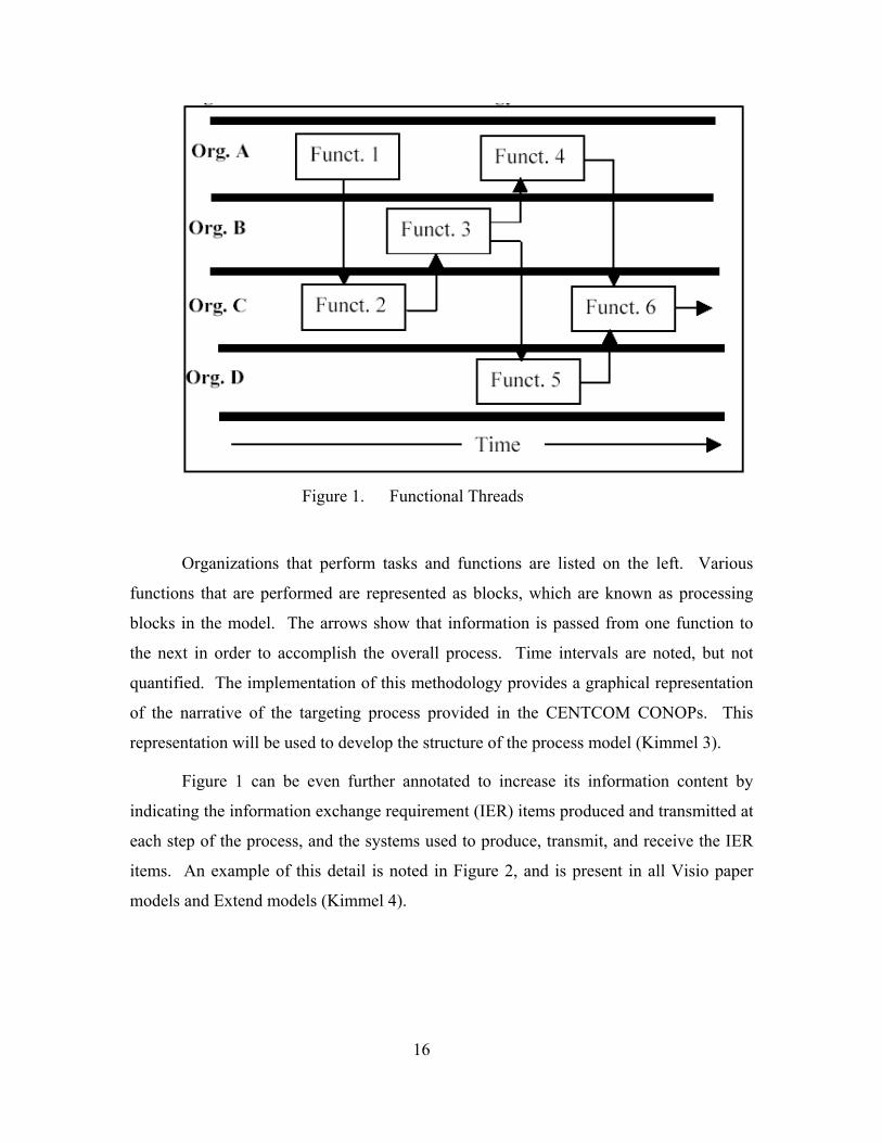
Figure 1. Functional Threads
Organizations that perform tasks and functions are listed on the left. Various
functions that are performed are represented as blocks, which are known as processing
blocks in the model. The arrows show that information is passed from one function to
the next in order to accomplish the overall process. Time intervals are noted, but not
quantified. The implementation of this methodology provides a graphical representation
of the narrative of the targeting process provided in the CENTCOM CONOPs. This
representation will be used to develop the structure of the process model (Kimmel 3).
Figure 1 can be even further annotated to increase its information content by
indicating the information exchange requirement (IER) items produced and transmitted at
each step of the process, and the systems used to produce, transmit, and receive the IER
items. An example of this detail is noted in Figure 2, and is present in all Visio paper
models and Extend models (Kimmel 4).
16
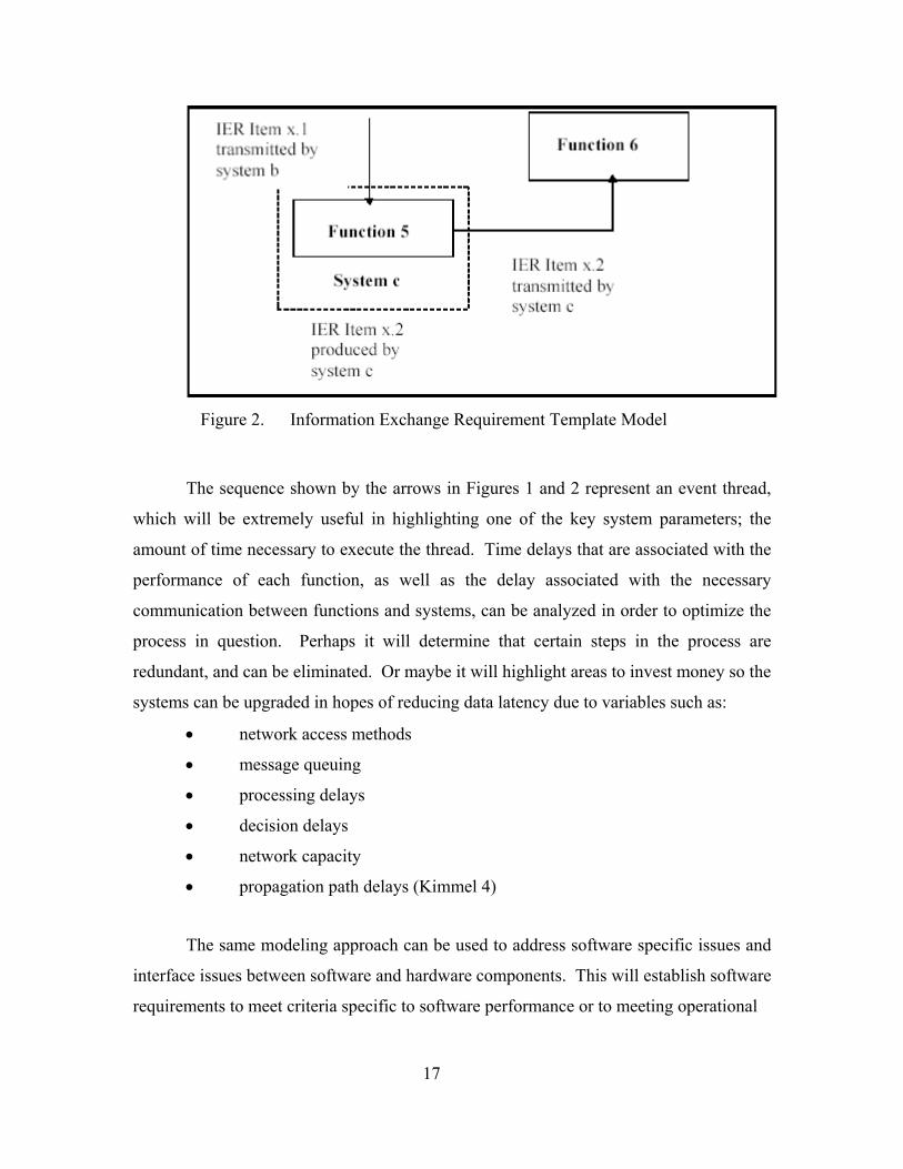
Figure 2. Information Exchange Requirement Template Model
The sequence shown by the arrows in Figures 1 and 2 represent an event thread,
which will be extremely useful in highlighting one of the key system parameters; the
amount of time necessary to execute the thread. Time delays that are associated with the
performance of each function, as well as the delay associated with the necessary
communication between functions and systems, can be analyzed in order to optimize the
process in question. Perhaps it will determine that certain steps in the process are
redundant, and can be eliminated. Or maybe it will highlight areas to invest money so the
systems can be upgraded in hopes of reducing data latency due to variables such as:
• network access methods
• message queuing
• processing delays
• decision delays
• network capacity
• propagation path delays (Kimmel 4)
The same modeling approach can be used to address software specific issues and
interface issues between software and hardware components. This will establish software
requirements to meet criteria specific to software performance or to meeting operational
17
objectives, including information structure and transmission protocols. In summary, this
modeling framework establishes the mechanism for examining interoperability effects
including:
• Effect of lack of connectivity between input and output systems on
process quality and completion times.
• Effect of lack of common formats used for input and output IER items on
process quality and completion times.
• Identification of critical processing nodes where interoperability factors
are crucial.
• Process/system blocking resulting from lack of interoperability.
• Process synchronization difficulties due to the timing of functions and the
production of IER items not being consistent with overall need times,
especially under high tempo conditions (Kimmel 4).
Most processes worth analyzing, including CENTCOM’s targeting architecture,
will include thousands of functional threads. This provides great opportunity to optimize
the system and reduce data latency; however, it would be impractical for humans to
model these processes and attempt to analytically solve the resulting equations. A far
more efficient method for modeling and simulating these processes is through the use of a
computer simulation tool.
E. COMPUTER SIMULATION
Simulations involve designing a model of a system and carrying out experiments
on it while taking the time domain into consideration. The major advantage of using
computer simulation environments to create and run models is to enable hypotheses, such
as altering link bandwidth or IERs. These can be tested at a fraction of the cost of
actually implementing these changes in the system in question.
Computer simulations are also advantageous due to the ability of the user to easily
conduct a “step-wise refinement” of the process (Extend v6 E4). Step-wise refinement
18
often results in accurate approximations to complex problems in a very time efficient
manner, and could more effectively communicate how the system really works.
Constructing models in these computer simulation environments facilitates
changing the model and quickly testing the effects of these changes. Some examples of
changes that can easily be made and tested are:
• Adding, replacing, or deleting activities and delays
• Changing the process flow
• Changing the process and delay times (Extend v6)
Additionally, computer simulations of process models can be constructed in order
to take interoperability issues into account. While interoperability tests have not been
directly incorporated into this baseline “Develop Targets” model, its framework does
facilitate the future addition of these checks. At appropriate locations in the model, tests
that are sensitive to interoperability issues can be inserted. The goal is to determine the
effect that interoperability deficiencies have on overall or local process performance.
Whether or not systems and information formats are interoperable is a technical question
that is answered external to the process model, and is an input to the model. The effect
such incompatibilities have is a process question that can be answered by process
modeling using the following method. Figure 3 illustrates how consideration of
interoperability is accomplished (Kimmel 5).
19
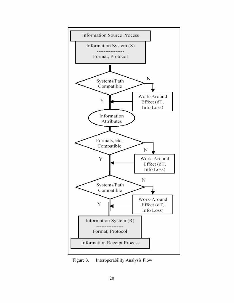
Figure 3. Interoperability Analysis Flow
20
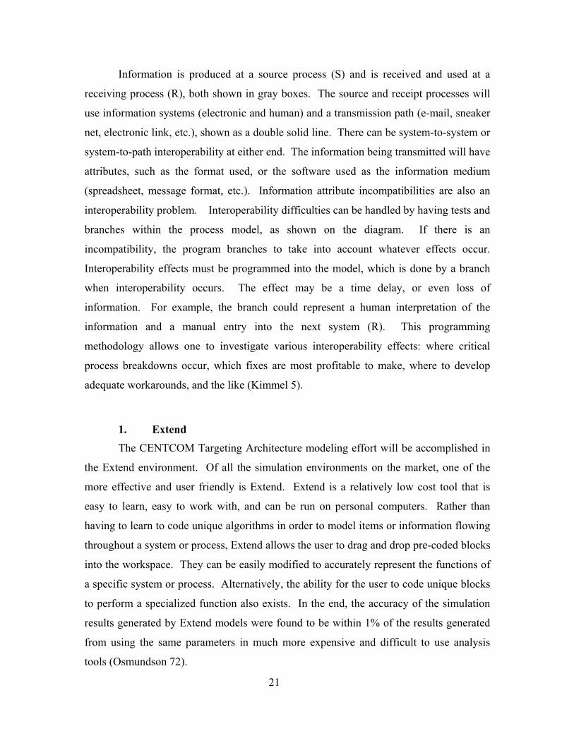
Information is produced at a source process (S) and is received and used at a
receiving process (R), both shown in gray boxes. The source and receipt processes will
use information systems (electronic and human) and a transmission path (e-mail, sneaker
net, electronic link, etc.), shown as a double solid line. There can be system-to-system or
system-to-path interoperability at either end. The information being transmitted will have
attributes, such as the format used, or the software used as the information medium
(spreadsheet, message format, etc.). Information attribute incompatibilities are also an
interoperability problem. Interoperability difficulties can be handled by having tests and
branches within the process model, as shown on the diagram. If there is an
incompatibility, the program branches to take into account whatever effects occur.
Interoperability effects must be programmed into the model, which is done by a branch
when interoperability occurs. The effect may be a time delay, or even loss of
information. For example, the branch could represent a human interpretation of the
information and a manual entry into the next system (R). This programming
methodology allows one to investigate various interoperability effects: where critical
process breakdowns occur, which fixes are most profitable to make, where to develop
adequate workarounds, and the like (Kimmel 5).
1. Extend
The CENTCOM Targeting Architecture modeling effort will be accomplished in
the Extend environment. Of all the simulation environments on the market, one of the
more effective and user friendly is Extend. Extend is a relatively low cost tool that is
easy to learn, easy to work with, and can be run on personal computers. Rather than
having to learn to code unique algorithms in order to model items or information flowing
throughout a system or process, Extend allows the user to drag and drop pre-coded blocks
into the workspace. They can be easily modified to accurately represent the functions of
a specific system or process. Alternatively, the ability for the user to code unique blocks
to perform a specialized function also exists. In the end, the accuracy of the simulation
results generated by Extend models were found to be within 1% of the results generated
from using the same parameters in much more expensive and difficult to use analysis
tools (Osmundson 72).
21

THIS PAGE INTENTIONALLY LEFT BLANK
22
IV. CENTCOM TARGETING PROCESS
This section is intended to provide a broad understanding of what is transpiring
throughout the entire joint targeting process. The ultimate goal of this cycle is to produce
an air tasking order (ATO) and then conduct a combat assessment of the target to
determine if a re-strike is required (Volume II 1-1).
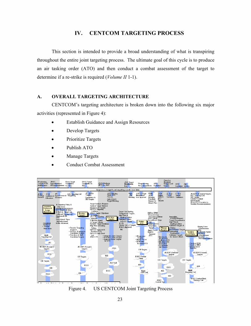
A. OVERALL TARGETING ARCHITECTURE CENTCOM’s targeting architecture is broken down into the following six major
activities (represented in Figure 4):
• Establish Guidance and Assign Resources
• Develop Targets
• Prioritize Targets
• Publish ATO
• Manage Targets
• Conduct Combat Assessment
Figure 4. US CENTCOM Joint Targeting Process
23
It is important to keep in mind this is not simply an end-to-end process that
happens only at the beginning of a conflict. This process must be viewed as an iterative
cycle in which it is not uncommon to have three or four air tasking orders in process at
any given time (Volume II 1-1).
During the “Establish Guidance and Assign Resources” activity the overall
guidance and priorities for targets are disseminated and the necessary operational
firepower required to satisfy this guidance is obtained (Volume II 1-7). The “Develop
Targets” activity identifies potential targets, unconstrained by assets needed to destroy
them, and begins to build up intelligence information about each target (Volume II 1-13).
The “Prioritize Targets” activity is necessary to merge the candidate target lists (CTLs)
from the component commanders, NCA, and JFC into a single, joint CTL. They are
prioritized based on commander’s guidance and current battle area situation (Volume II 1-
24). This prioritized, joint CTL is then used in the “Publish ATO” activity to create an
ATO for use the following air tasking day. The ATO is important because it informs the
component commanders of the air support they should receive, while coordinating all
flying operations for that day (Volume II 1-33). While considerable effort goes into
producing the ATO, the continuously evolving nature of the tactical environment often
makes the ATO’s exact execution impossible. The “Manage Targets” activity handles
the changes in asset availability, weather conditions, combat losses and emerging targets
by ensuring that the objectives of the ATO are satisfied through alternate, yet
coordinated, means of execution (Volume II 1-42). Finally, the “Conduct Combat
Assessment” activity is necessary to determine whether the target was destroyed, and to
gauge its effect on the overall campaign. Also, this activity serves to analyze the
effectiveness of the weapons, tactics and strategies employed, and makes re-strike
recommendations if necessary (Volume II 1-53).
A basic understanding of CENTCOM’s joint targeting architecture is important
when analyzing and modeling any of the six major activities. The remainder of this
thesis will focus specifically on the “Develop Targets” activity, which is described in far
greater detail in the following section.
24
B. DEVELOP TARGETS ACTIVITY
The “Develop Targets” activity involves a systematic examination and evaluation
of potential enemy military, political, and economic target systems, and identifies their
components and interrelationships. Potential military destructive and nondestructive
actions are considered. Ultimately, candidate target selection is made based on the
target’s contribution to the established campaign and command objectives within the
scope of the command guidance. “Develop Targets” is divided into three sub-activities
(Volume II 1-14):
• Provide Targeting Support
• Receive and Integrate Candidate Targets
• Prioritize and Staff Candidate Targets
The following narrative is best understood in conjunction with the accompanying
Visio paper model. This Visio model (400 KB) is available on the Internet site
<http://library.nps.navy.mil/uhtbin/hyperion/04Jun_Germakian> under the link “Develop
Targets Paper Model in Visio.” The Visio paper model was an important first step in
ultimately developing a working model of this activity in Extend. It transformed the
written information in CENTCOM’s documentation of the joint targeting architecture
into a visual representation of this process in the form of an organizational architecture.
In this form, it was easier to understand not only the key organizations involved
throughout the process, but also allowed IERs, functional threads, and information gaps
to be readily identified. Ultimately, the paper model made the creation of the Extend
model more fluid.
Together, the Visio paper model and the following narrative provide a sense of
when the processes occur throughout the activity and highlight the data elements that
flow between the organizations. This model and process may not be entirely accurate
due to information gaps in the documentation, which is why future iterations will be
necessary. Furthermore, any assumptions regarding the flow of information between
organizations are annotated in the text, and defined by a red information exchange lines
in the Visio diagram, as opposed to documented information exchange lines that are blue.
25
1. Provide Targeting Support During the “Provide Targeting Support” sub-activity, each member of US
CENTCOM’s targeting community participates in an early examination of potential
theater targets. Their goal is to select those targets that best support the component
commander’s war effort based on the JFC’s strategy, objectives and guidance. Target
nominations are selected from a USCENTCOM Preplanned JTL, and intelligence needs
are satisfied throughout the target folder development process. JICCENT Targets is the
organization that drives “Provide Targeting Support.” Throughout this sub-activity
existing target databases are updated, collection requirements are both generated and
satisfied, and the best employment of available assets is determined (Volume II 1-13).
a. Initial Target Selection Process
• This relies heavily upon information that was created and disseminated to component commanders and targeteers during the “Establish Guidance and Assign Resources” activity. The following information, which has been previously disseminated, serves as the basis upon which the initial target lists will be developed: Joint Target Policy and Objectives, Preplanned Joint Target List, FSCL, OPLAN/OPORD/FRAGO, Joint No-Fire Target List, JFC Weight of Effort and Collateral Damage List. This “initial guidance package” is assumed to have already been distributed to all targeteers involved in developing targets and is not depicted in the Visio diagram of “Develop Targets.”
• Initial target nominations are produced by JICCENT Targets, CID targets, COID targets, and the ACE upon receipt of the startup target database from the NMJIC. These target nominations do not yet take into consideration the assets needed to destroy them, but rather select a number of targets for which additional information will be gathered. Although not mentioned in the documentation, it was assumed that the JFMCC and JFSOCC also begin their initial target selection process at this time.
b. Acquire Additional Target Intel
• The component commanders and targeteers identify shortfalls in targeting materials and relay this information in the form of target material requests through JICCENT Targets to JICCENT (rear)
26
Target Materials Branch and NIMA. The information exchange from JICCENT Targets to NIMA is assumed, but likely to occur since it is known that NIMA submits target materials back through JICCENT Targets.
• The requested target material products (Basic Target Graphics and Quick Response Graphics) are processed and disseminated back down to the component commanders, and ultimately the targeteers in the form of graphic, textual, tabular, digital, video and other JICCENT (rear) presentations of target intelligence in support of operations.
• Concurrently, JICCENT Targets reaches back to NMJIC Targets for support on the analysis of specific targets and target systems. The NMJIC serves as the pipeline to CONUS-based intelligence agencies, which can sometimes provide more detailed target analysis. Upon completion these requests are assumed to be pushed forward through JICCENT Targets to deployed targeteers as necessary.
• The targeteers and component commanders review the target materials, and subsequent intelligence shortfalls are submitted to JICCENT DARS, the daily aerial reconnaissance and surveillance conference, in the form of collection requirements. Although documented to flow from the ACE, JFACC and JICCENT Targets to JICCENT DARS, it is assumed that these collection requirements are also generated by the targeteers. JICCENT DARS tasks the SOF and S&R sensors to fulfill organic surveillance and reconnaissance collection requirements. The DCCC is tasked with national asset collection requirements. Completed collection requirements are pushed back through JICCENT DARS to the component commanders. It is assumed that the targeteers also receive the completed collection requirements.
• Concurrently, JICCENT Targets also integrates WMD target information into the evolving target database through information gathered from S&R sensors.
c. Disseminate Appropriate Target Information
• JICCENT Targets compiles and disseminates tactical target
material to component commanders and targeteers. This information consists of the targeting systems and materials that a targeteer will have available when deployed.
27
• Simultaneously, an updated target database and specific criteria regarding the JFC’s specific guidance for target categories and
standards on which targeting nominations may be made are distributed to the targeteers. It is assumed that this same information is sent to the maritime and special operations component commanders as well.
2. Receive and Integrate Candidate Targets During “Receive and Integrate Candidate Targets” sub-activity, the selection of
deep operations targets is conducted by Army forces, Marine forces, the Deputy Joint
Force Land Component Commander (DJFLCC), JFACC and JFC targeting staffs. JFC
guidance and objectives, location of the FSCL, rules of engagement, and target
intelligence gathered in the previous sub-activity are all taken into consideration prior to
the development of DJFLCC, JFACC and JFC initial candidate target lists (CTLs).
These preliminary CTLs are unconstrained by the availability of attack resources.
Development of the JFC, JFACC and DJFLCC CTLs should be occurring in parallel,
although this is not represented well in the Visio diagram due to the fact that the DJFLCC
process is described in the most detail. Also note that JFMCC and JFSOCC targets are
incorporated into the JFACC CTL via Liaisons located at the AOC (this information
exchange is not modeled).
a. DJFLCC CTL Development
• An updated target database, ROEs, any changes in the FSCL, and
JFC guidance and objectives serve as the foundation for the unconstrained nomination of ground targets by the ACE, SJA, and Army and Marine forces. Each of these organizations sends its candidate ground target list to the DOCC.
• The DOCC, which is also aware of ROEs and changes to the FSCL, integrates its own ground target nominations with those received from the aforementioned agencies.
• It is assumed that the initial ground target nominations are passed from the DOCC to the ACE and DJFLCC Staff. Based on a 72 to 96 hour intelligence estimate from the ACE, the DJFLCC staff conducts an operations-intelligence war gaming session to determine the DJFLCC scheme of maneuver and fire support for the next 72 to 96 hours. Accurate targeting guidance and objectives are relayed to the DOCC.
28
• The DOCC develops an initial DJFLCC CTL based on the targeting guidance and objectives.
• The DOCC also distributes any disapproved targets to the component targeting elements so that they are aware, and can re-submit for approval, if needed.
• The ACE begins its preparation and research of maps, plots and briefing folders to further enhance DJFLCC CTL target intelligence.
b. JFACC CTL
• The BCD cell is notified of any changes to the FSCL.
• The JFACC AOC Combat Plans Target Development Section, consisting of members of the 609 AIS, is responsible for all air component targeting and begins development the JFACC CTL.
• The JGAT cell disseminates JFACC targeting objectives and guidance to the air components; MAW, WOC and JFMCC. It is assumed that these objectives and guidance must have been based on the JFACC CTL, and therefore, the JGAT cell should have received some form of input from AOC Combat Plans.
c. JFC CTL
• The JFC is notified of any changes to the FSCL and integrates its
own target nominations list with ground target nominations submitted by JFSOCC and F2C2.
• JICCENT Targets, which has also created an initial list of targets, integrates ground target nominations from the JFC and NMJIC to begin development of the JFC CTL.
• JICCENT Targets prepares and disseminates disapproved targets and target objectives and guidance to the targeting components involved: NMJIC targets, JFC, F2C2 and JFSOCC.
• JICCENT Targets also begins its preparation and research of maps, plots and briefing folders to further enhance JFC CTL target intelligence.
3. Prioritize and Staff Candidate Targets During this final sub-activity, each component prioritizes and staffs their final
CTL before submitting it to the AOC. Again, DJFLCC has the most detailed process,
and it was assumed that the JFC and JFACC also prioritize and staff their final CTLs
29
before they are sent to the AOC. In addition to producing a DJFLCC approved and
prioritized CTL, a daily divert list is developed and submitted to the AOC to identify high
priority ground force targets should JFACC sorties become available. Although neither
documented, nor modeled, the JFC and JFACC may also develop a list similar to
DJFLCC daily diverts.
a. DJFLCC Approved and Prioritized CTL and Daily Diverts
• The initial DJFLCC CTL compiled by the DOCC is submitted to
the DJFLCC staff for recommendations from personnel such as the SJA, engineer, and PSYOPs officer. These recommendations are incorporated, and the CTL is prioritized and re-submitted to the DJFLCC staff for final approval.
• The DOCC also develops the Daily Divert List, which is sent along with the prioritized and staffed CTL to the AOC BCD cell.
• Final maps, plots and briefing folders that were produced by the ACE are received by the DJFLCC.
b. JFACC Prioritized and Staffed CTL
• AOC Combat Plans is assumed to prioritize and staff the JFACC
CTL, and send it to CID targets.
• Final maps, plots and briefing folders are produced by CID targets and sent to the AOC.
c. JFC Prioritized and Staffed CTL
• JICCENT Targets is assumed to prioritize and staff the JFC CTL,
and send it to CID targets.
• Final maps, plots and briefing folders that were produced by JICCENT Targets are received by the JFC.
The principle outputs at the conclusion of the “Develop Targets” activity
are prioritized and staffed CTLs, and current maps, plots and briefing folders.
These will serve as the major inputs that drive the following activity, “Prioritize
Targets.” 30

C. ORGANIZATIONS WITHIN DEVELOP TARGETS
All of the tasks required to complete “Develop Targets” are not accomplished at a
single location or by a single organization. At the top of the chain of command in the
area of responsibility is the Joint Force Commander (JFC). The organization is then
broken down into the component commands of: Deputy Joint Force Land Component
Commander (DJFLCC) (the JFC retains functional responsibility for the joint force
land component), Joint Force Air Component Commander (JFACC), Joint Force
Maritime Component Commander (JFMCC), and Joint Force Special Operations
Component Commander (JFSOCC) (Volume I 1-7). Each of the component commanders
represents a different area of the joint battlefield. The DJFLCC is in charge of ground
operations, the JFACC is in charge of air operations, the JFMCC is in charge operations
at sea, and the JFSOCC is in charge of the special operations forces that are in the area of
responsibility. These component commands are further divided into numerous
organizations to conduct their missions. They also utilize outside organization when they
do not have all the information required to accomplish their tasks (Volume I 3-2). The
following are the organizations that perform a role in “Develop Targets.”
1. ACE The Analysis and Control Element (ACE) is the intelligence node for the
DJFLCC (Volume III D-3). The ACE performs many roles for the DJFLCC. First, it
assists in the development of all intelligence estimate products and special studies for
deep operations. Second, it produces target and briefing folders, wargames friendly
ground force operational plans, and determines deep attack, high-value, and high-payoff
targets. It also coordinates with the ACE intelligence collection manager to satisfy
priority intelligence requirements, conducts detailed intelligence analyses of enemy
forces, and develops a prioritized candidate target list based on DJFLCC targeting
guidance and objectives. Finally, it conducts damage assessments of targets struck, and
validates candidate targets 8 and 4 hours before mission strike (Volume 1 3-10,11).
The ACE performs several duties during “Develop Targets.” The first job for the
ACE is conducting operations-intelligence wargaming sessions to determine DJFLCC
scheme of maneuver and fire support for next 72-96 hours. Later in “Develop Targets,” 31
the ACE, based on DJFLCC approved courses of action, receives guidance from the
DOCC and DJFLCC subordinate commands for candidate target development. Finally, it
identifies high-value targets, recommends high-payoff targets, and researches, prepares
and distributes special studies as part of its target folders. (Volume II 13-23).
2. BCD The Battlefield Coordination Detachment (BCD) is located in Ft. Bragg, North
Carolina. Its mission is to facilitate the synchronization of joint air operations with Army
ground maneuver and fires, to coordinate joint air support, and to facilitate the exchange
of operational and intelligence data (Volume 1 3-5). It also conducts extensive
coordination during the planning phase of operations (Volume II 13-23). The BCD is
divided into seven areas of operation. They are Current Intelligence, Future Intelligence,
Operations, Air Lift, Plans, Airspace Management, and Air Defense Artillery. It is
staffed with 15 officers and 17 enlisted personnel (Volume 1 3-5). During the “Develop
Target” activity, the BCD receives the DJFLCC approved and prioritized candidate target
list via AFATDS (Volume II 13-23).
3. CID Targets The Combat Information Division (CID) Targets is the targeting node within the
Air Operations Center (AOC) under the JFACC. It provides target development and
conducts battle damage assessment in the targeting cycle (Volume III D-3). During the
planning phase of operations, CID Targets conducts extensive coordination. (Volume II
13-23).
4. COID Targets The Combat Operations Intelligence Division (COID) Targets is very similar to
CID Targets. It is also a targeting node within the AOC under the JFACC. However,
instead of planning an operation, COID Targets provides target management during the
execution of the ATO (Volume III D-3).
5. DCCC The Defense Collection Coordination Center (DCCC) provides a central node for
consolidating requirements for national collection. It is collocated with the NJMIC 32
(Volume III D-4). The DCCC receives integrated component collection requirements that
are presented by JICCENT collection manager at the DARS Conference for national asset
collection (Volume II 13-23).
6. DJFLCC The Deputy Joint Force Land Component Commander (DJFLCC) is designated
the duties, functions, and responsibilities of the Joint Force Land Component
Commander (JFLCC). This is because the JFLCC is designated the Joint Forces
Commander. The DJFLCC has a staff, and the staff is responsible for providing inputs to
targeting recommendations that result in the DJFLCC approved and prioritized candidate
target list. The DJFLCC also has a Staff Judge Advocate (SJA) who provides guidance
for the legal aspects of targeting, such as collateral damage, the law of armed conflict,
and the rules of engagement (Volume III D-4).
During “Develop Targets,” the DJFLCC has many roles. His guidance and
objectives allow for fixed and mobile targets to be nominated, and his targeteers provide
coordinates to JFACC targeteers during target nomination. The DJFLCC planners work
with ACE intelligence personnel to discuss, dissect, and fuse information concerning
friendly operations to develop the best course of action for the ground component forces.
Finally, one of the primary products of the “Develop Targets” activity is the production
of a DJFLCC approved and prioritized candidate target list (Volume II 13-23).
7. DOCC The Deep Operations Coordination Cell is the division within the DJFLCC staff
tasked with planning, coordinating, and executing deep attacks (Volume III D-4). Its
headquarters are located at Fort McPherson in Atlanta, Georgia. The DOCC coordinates
targeting guidance and objectives input into the ATO, ATO execution, and fire
support coordination measures. It also maintains the DJFLCC daily divert list. It is
divided into the three sections of Target Development, Battle Management, and Fire
Support. The DOCC is staffed with 15 officers, 2 warrant officers, 11 noncommissioned
officers, 24 Air Force augmenters, along with additional personnel assigned depending
on the scope of the operation (Volume 1 3-8).
33
The DOCC serves as a focal point for the DJFLCC to receive Army and Marine
CTLs as well as developing its own targets. During "Develop Targets," it consolidates
the received targets into a single integrated list of ground targets. The DOCC also
coordinates the predicted locations of maneuver forces to counter the targets on the move
(Volume II 13-23).
8. F2C2 The Friendly Forces Coordination Center (F2C2) passes coalition-nominated deep
attack targets to United States target planners at the AOC. It serves as a link between
targeting, planners, operators, and coalition forces. During “Develop Targets,” the F2C2
sends the coalition target nominations to JICCNET Targets (Volume II 13-23).
9. JFACC The Joint Forces Air Component Commander (JFACC) is responsible for
planning, coordinating, allocating, and tasking, as well as recommending to the JFC air
sorties to various missions or geographical areas (Volume III D-4). Being one of the four
component commanders, the JFACC has many activities in “Develop Targets.” One of
the primary outputs of “Develop Targets” is the JFACC approved CTL. This approval
CTL incorporates the targets provided by the JFMCC and JFSOCC. Under the JFACC,
the AOC conducts air component targeting, and the JFACC Combats Plans is responsible
for the air component targeting regardless of service (Volume II 13-23).
10. JFC The Joint Force Commander (JFC) is the person who is authorized to execute
command authority or operational control over a joint force (Volume III D-5). The JFC is
the person to whom the component commanders (DJLFCC, JFACC, JFSOCC, and
JFMCC) report (Volume I 3-2). The JFC has a staff that provides targeting
recommendations that aid the JFC in guidance, apportionment, and weight of effort. The
JFC also has a SJA who provides guidance for the legal aspects of targeting (Volume III
D-5).
34
11. JFMCC
The Joint Force Maritime Component Commander is responsible for making
recommendations on the proper employment of maritime forces and assets, planning and
coordinating maritime operations, or accomplishing similar missions as may be assigned
(Volume III D-5). In “Develop Targets,” the JFMCC sends its target nominations to be
incorporated in the JFACC CTL that is sent to the next activity of prioritize targets
(Volume II 13-23).
12. JFSOCC The Joint Force Special Operations Component Commander (JFSOCC) is
responsible for making recommendations on the proper employment of special operations
forces and assets, planning and coordinating special operations, or accomplishing a
similar operational mission as assigned by the JFC (Volume III D-5). As one of the four
component commanders, during “Develop Targets” the JFSOCC sends target
nominations to be incorporated into the JFACC CTL (Volume II 13-23).
13. JGAT Cell The Joint Guidance, Apportionment, and Targeting (JGAT) Cell approves the
joint integrated prioritized target list (JIPTL) and determines a cut line above which
prioritized targets can be serviced by available weapons. Once this list is approved by the
JFACC, it become the target nomination list. (Volume III D-5) Organizationally, the
JGAT Cell is in the JFACC Air Operations Center (AOC) (Volume II 1-64). During the
“Develop Targets” activity of the joint targeting architecture, the JGAT Cell sends the
JFACC targeting objectives and guidance to JFMCC, WOC, and MAW (Volume II 13-
23).
14. JICCENT The Joint Intelligence Center at CENTCOM (JICCENT) refers to the forward-
deployed portion of JICCENT that serves as the intelligence center at the joint
headquarters. It is responsible for providing and producing intelligence required to
support the JFC and staff, components, task forces, elements, and the national
35

intelligence community (Volume III D-5). It is organizationally positioned under the JFC
and contains Targets, WMD, and DARS branches (Volume II 1-66).
15. JICCENT (Rear) The JICCENT (Rear) is the portion of the JICCENT remaining at MacDill Air
Force Base while the joint force is deployed in the theater (Volume III D-5). During
“Develop Targets,” JICCENT (rear) is able to process information it has received from
the front, and push results and additional information from its large databases back to
assist in mission accomplishment. During “Develop Targets,” JICCENT (rear) initially
produces target materials, basic target graphics, and quick reaction graphics and sends
them to the front over GBS. Its also receives all identified shortfalls in targeting
materials to examine whether it has the information needed. A third method JICCENT
(rear) supports the targeting process is through a Joint Mapping Coordination Center
(JMCC) which provides specialized mapping and imagery support to the Command and
ensures NIMA satisfies the Commands imagery and mapping requirements (Volume II
13-23).
16. JICCENT DARS The JICCENT Daily Aerial Reconnaissance and Surveillance (DARS)
Conference determines the best use of organic collection resources to satisfy collection
requirements (Volume III D-5). The DARS Conference is the mechanism JICCENT uses
to exercise collection and production management authority throughout the theater. The
component commanders’ managers use this DARS Conference to consolidate
surveillance and reconnaissance requirements. Among those component commanders,
the JFACC battlespace managers use the DARS developed collection plan to task organic
collection assets using the ATO process (Volume II 13-23).
17. JICCENT Targets
The JICCENT Targets branch conducts theater-level targeting and battle damage
assessment. It consolidates theater and national level targets and passes them to the
JFACC AOC for inclusion in the ATO (Volume III D-5). JICCENT Targets is located
within JICCENT (forward) along with the WMD Cell and DARS. JICCENT Targets
36
plays a significant role in “Develop Targets.” First, it receives proposed component and
national agency target nominations and integrates them into a Preplanned JTL. It then
submits target analysis requests to the NJMIC. Based on the tactical environment and
intelligence reports, JICCENT Targets provides an updated target database and joint
criteria for target selection to the components. One of JICCENT Targets larger roles is to
“Develop Targets” for the JFC. It accepts nominations from the JFC, JFSOCC, F2C2,
and NMJIC Targeting Cell, while developing its own unconstrained list of targets.
These nominations are combined to form the JFC CTL, which is then ready for
JFC staff coordination. Targets not approved are returned to the submitting command or
F2C2 to re-enter the cycle and compete again for priority on the CTL. (Volume II 13-23).
18. JICCENT WMD Cell The JICCENT Weapons of Mass Destruction (WMD) Cell provides analytical
support for the tracking and identification of WMDs (Volume III D-6). During target
development, once a S&R Sensor detects a WMD, it is passed to the JICCENT Targets
Branch via the SIPRNET or JWICS (Volume II 2-30).
19. JOC The Joint Operations Center (JOC) is responsible for planning, monitoring, and
guiding the execution of the JFC’s decisions (Volume III D-6). The JOC is a key
decision making node in the targeting architecture and is organizationally under the JFC
along with JICCENT (forward) (Volume II 1-49).
20. JTCB
The Joint Target Coordination Board (JTCB) is a group responsible for targeting
oversight that includes coordinating targeting information, providing targeting guidance
and priorities, and preparing and refining joint target lists (Volume III D-6). To fulfill its
oversight role, the JTCB meets daily during crisis and hostilities. The board is chaired by
the Deputy Joint Force Commander, with membership comprising the
USCENTCOM Director of Intelligence (J2) and Director of Operations (J3),
DJFLCC, JFACC, JFMCC, JFSOCC, and other component-level representatives
(Volume II 1-10).
37
21. MAW
The Marine Aircraft Wing (MAW) provides aircraft and tactical air control in the
amphibious operations area. When they are available, MAW aircraft are tasked to
support the JFACC in meeting the JFC’s apportionment decisions (Volume III D-6).
22. NIMA The National Imagery and Mapping Agency (NIMA) is a combat support agency
that provides timely, relevant and accurate imagery, imagery intelligence, and geospatial
information (Volume III D-7). NIMA’s strategic goals are to provide seamless access to
tailorable imagery, make this information available quickly, obtain the best available
information, and use private sector services and the best available technologies (Volume
III C2-145). During “Develop Targets,” NIMA sends target materials to JICCENT
Targets (Volume III E-16). In late 2003, NIMA changed its name to the National
Geospatial-Intelligence Agency (NGA). It is headquartered in Bethesda, Maryland, and
operates major facilities in the St. Louis, MO. and Washington, D.C. areas. The Agency
also fields support teams worldwide (NGA).
23. NMJIC Targeting Cell The National Military Joint Intelligence Center (NMJIC) Targeting Cell responds
to requests for information, aids in target list development, and assist with battle damage
assessment (Volume III D-19). This cell stands up during crisis situations, and can
provide specific targets, guidance, and targeting support by way of special studies,
analyses and databases. It is CENTCOM’s targeting community pipeline to CONUS
based intelligence agencies. For the “Develop Targets” activity during the targeting
architecture, the NMJIC Targeting Cell distributes the startup target database, and
receives, processes, and transmits several key pieces of information (Volume II 13-23).
24. S&R Sensors Surveillance and Reconnaissance (S&R) sensors refer to the many technical
means of collecting intelligence data within the battlespace (Volume III D-7).
38
25. SOF
Special Operations Forces (SOF) are specialized military units designed to
confront a wide variety of situations ranging from peacetime threats to open warfare.
Special Forces main duties include counter-proliferation, counter-terrorism,
reconnaissance, small-scale direct action, psychological operations, civil affairs, foreign
internal defense, and "unconventional" warfare (Special).
A SOF can act as a surveillance and reconnaissance asset that provides near-real-
time reporting and allows expeditious adjustments to the ATO. It also plays a critical
role as human sensors in identifying emerging high-payoff targets for potential
immediate attack (Volume II 1-47,61).
26. WOC The Wing Operations Center (WOC) is the central information node supporting
Air Force flying operations (Volume III D-7).
D. SYSTEMS UTILIZED DURING DEVELOP TARGETS In order to better coordinate and communicate, the organizations in “Develop
Targets” use many different systems to develop and transmit their information. The four
primary types of systems are surveillance and reconnaissance, intelligence data handling,
targeting, and command and control (Volume II 2-28). The following are system utilized
during “Develop Targets.”
1. AFATDS The Advanced Field Artillery Tactical Data System (AFATDS) is a totally
integrated fire support C2 system (AFADTS 1998). It is a network of computer
workstations that processes and exchanges information from the forward observer to the
fire support element for all fire support assets. These assets include field artillery,
mortars, naval gunfire, attack helicopters, and close air support. The major features of
AFATDS are automatic processing of fire requests, generation of multiple tactical fire
solutions for missions, monitoring of mission execution, and support for the creation and
distribution of fire plans (AFATDS 2001). 39
Through the use of distributed processing capabilities, fire missions will flow
through the fire support chain during which target attack criteria will be matched to the
most effective weapon systems available at the lowest echelon. The automation provided
by AFATDS will enhance the maneuver commander's ability to dominate the battle by
providing the right mix of firing platforms and munitions to defeat enemy targets based
on the commander's guidance and priorities. During battle, AFATDS will provide up-to-
date battlefield information, target analysis, and unit status, while coordinating target
damage assessment and sensor operations. AFATDS will also meet field artillery needs
by managing critical resources; supporting personnel assignments; collecting and
forwarding intelligence information; and controlling supply, maintenance, and other
logistical functions (AFATDS 1998).
2. JDISS The Joint Deployable Intelligence Support System (JDISS) program provides a
family of hardware and software capabilities that allow connectivity and interoperability
with intelligence systems deployed during peace, crisis, and war (Pike JDISS). JDISS
provides access to imagery, finished intelligence products, and assists in putting together
the order of battle. JDISS allows Joint, National, and Coalition users to access databases
across the intelligence community. JDISS is not an intelligence system, it is an
intelligence support system. It has no intelligence database, no strictly intelligence
applications, no map graphics, and no capability to process NRT intelligence (Shannon).
The core software for JDISS is:
• E-mail/chatter
• Word processing/message generator
• Imagery manipulation
• Communications interfaces/map graphics
• Briefing tools/utilities
• Desktop video/voice (Pike JDISS)
40
JDISS is the primary intelligence data handling system used in “Develop
Targets.” It is utilized by organizations in JICCENT and the NMJIC Targeting Cell. The
flexibility to transmit many different types of data and the important role JICCENT plays
in “Develop Targets” leads to JDISS being used frequently (Volume II 13-23).
3. ASAS The All-Source Analysis System (ASAS) is a program to automate the processing
and analysis of intelligence data from all sources. ASAS is a tactically deployable,
ruggedized, and automated information system (Pike ASAS). ASAS contributes to
attaining information superiority through a network of computer workstations that
process and exchange sensor data, fuse multi-source data into a single intelligence
picture, and support management of intelligence sensors. ASAS is tactically deployable
to support intelligence and electronic warfare operations at battalion through echelons
above corps (ASAS).
4. JCMT
The Joint Collection Management Tools (JCMT) is a migration system for all-
source collection management, combining IMINT, SIGINT, MASINT, and HUMINT
tasking. This software-only package provides the tools for gathering, organizing, and
tracking intelligence collection. JCMT is used by national, theater, and tactical
organizations of all services. JCMT parses over 30 collection management messages into
its databases; it can also store any message type for user review. JCMT also accesses
numerous technical references and national SIGINT and HUMINT standing requirements
(Pike JCMT).
JCMT works by collection requirements being generated by war fighters and then
allocated to a Collection Management Authority (CMA). The CMA uses the JCMT to
provide an overview of the requirements database. JCMT assists the CMA in determining
the appropriate collection platform or mix of assets required to perform the mission.
Finally, the CMA's collection management system provides the reconnaissance feedback
to the war fighters who originated the requests for information (Pike JCMT). In
41
“Develop Targets,” JCMT is used very sparingly, only to distribute Collection
requirements. The primary intelligence data handling system used in “Develop Targets”
is JDISS (Volume II 2-28).
5. GCCS The Global Command and Control System (GCCS) is an integrated, reliable, and
secure command and control system linking the National Command Authority down to
the Joint Task Force and Component Commanders. It provides seamless battlespace
awareness and a fused battlespace picture by exchanging data, imagery, intelligence,
status of forces, and planning information. GCCS employs client/server architecture
using commercial software and hardware, open systems standards, office automation,
government developed military planning software, and worldwide web technology. Also,
it rides on the (SIPRNET) communications backbone, or it can be accessed from dial-in
remote terminals (GCCS). GCCS incorporates the core planning assessment tools
required by combatant commanders and their subordinate joint force commanders and
meets the readiness support requirements of the Services (Logistics).
GCCS is the primary C2 system used in the “Develop Targets” activity in the
CENTCOM targeting architecture. In this particular activity, GCCS is used to distribute
the FSCL, FSCL changes, joint target policy and objectives, and the rules of engagement.
All of the information GCCS distributes is sent over the SIPRNET (Volume II 2-28).
GCCS-A is also used in the “Develop Targets” activity. GCCS-A is
fundamentally GCCS with additional Army functionality. It will provide a single
seamless command and control system and is being integrated with the GCCS.
6. IPA The Image Product Archive (IPA) supports the storage and dissemination of
imagery and imagery products, providing a library of information to imagery customers
worldwide. IPA supports both data push and data pull via user profiling and stores
imagery in NITF 2.0, TIFF, and other formats. IPA is capable of importing, storing,
exporting and managing imagery, and image-based products. It has the capability to
retain digital imagery data in on-line, near-line, and off-line storage media. The IPA
42
supports up to 1300 image requests per day and up to 900GB for on-line imagery storage.
The IPA should not take longer than eight minutes to transfer a full frame (930MB)
national image to any requesting Client, assuming Fiber Distributed Data Interface, FDDI
interface(s) and no LAN contention (Pike IPL).
At the highest level of abstraction, the imagery production process is similar for
all types of imagery. Imagery data is collected and sent to an initial processor; from this
processor the data is sent through a dissemination system to a library or database. The
imagery files are copied from the database to an exploitation system where intelligence
products are generated; the resulting imagery products are returned to the database.
Authorized users can access the images they need from this database. This entire process
takes place within SCI enclaves for most types of imagery, even though most imagery is
at the Secret Collateral level (Pike IPL).
7. JMCIS Joint Maritime Command Information System (JMCIS) was the Navy’s primary
C2 system afloat. In recent years this system has been replaced by the Navy’s version of
GCCS. The JMCIS provided a single integrated C4I system that received, processed,
displayed, maintained and assessed the unit characteristics, employment scheduling,
material condition, combat readiness, warfighting capabilities, positional information and
disposition of own and Allied forces. This allowed decision makers to optimize the
allocation of resources. JMCIS had state-of-the-art command center support capabilities
that kept pace with changing threats and evolving requirements. JMCIS provided current
geolocational information on hostile and neutral land, sea and air forces integrated with
intelligence and environmental information, and near real time weapons targeting data to
submarines (Pike JMCIS).
The JMCIS implemented a hardware and software architecture consistent with the
Common Operating Environment (COE) specifications defined by the Global Command
and Control System (GCCS). The hardware configuration for JMCIS systems were a
Navy standard desktop tactical-support computer. Fleet units relied on support from
centers ashore for processing high volume data from non-organic sensors, and for the
43
picture of the battle space beyond the range of the afloat force's organic sensors (Pike
JMCIS). All of these functions of JMCIS are currently handled by Navy’s version of
GCCS.
8. S&R Systems Surveillance and reconnaissance (S&R) systems represent all of the S&R assets
available to the joint force (Volume III D-10).
9. TBMCS The Theater Battle Management Core Systems (TBMCS) provides Joint and
Service Combat Air Forces with automated command, control, communications,
computer, and intelligence systems to plan and execute theater-level air campaigns.
TBMCS is the theater air module of the GCCS. One of the TBMCS applications
provides an integrated air picture updated from a number of theater and strategic sensors
and organizations. This integrated air picture, along with the fused intelligence provided
by interaction with other Service intelligence systems, supports increased situational
awareness (TBMCS).
The mission of TBMCS at the force level is to provide the Joint and Combined
Air Component Commander with the automated tools necessary to effectively and
efficiently plan, monitor, and execute the air campaign. This includes planning and
issuing the air tasking and air control orders that ensure the Theater Commander's intent
is supported through the application of airpower using the latest intelligence. TBMCS
capabilities should also ensure that air operations are de-conflicted. The mission of
TBMCS at the unit level is to provide the wing and base commanders and their battle
staffs with timely and accurate information for effective decision-making. TBMCS is also
supposed to provide the secure, automated, deployable, and distributed Wing-Level
Command and Control System with connectivity to force-level TBMCS systems
(TBMCS).
10. JTT The Joint Targeting Toolbox (JTT) is part of an intelligence suite that can be
integrated onto the TBMCS. The JTT is employed to effectively apply the right weapon
44
on the right target at the right time (Ferens). It is the primary targeting application for the
GCCS that allows complete targeting interoperability within the joint community. JTT is
a group of software modules that supports the entire targeting cycle, with the goal of
leveraging off of current targeting applications by packaging their functionality into a
non-duplicative collection of interoperable targeting tools (Joint Targeting).
JTT provides a capability to rapidly receive, correlate, manipulate, display and
disseminate target intelligence data from multi-discipline sources and apply the resulting
information to the battle planning, mission execution and assessment processes. JTT
brings all Services’, Commands’, and government agencies’ targeting requirements
together in one tool (Joint Targeting). JTT can perform all phases of the targeting cycle
in near real time. It has a capability that allows users to label data with appropriate
classifications, which is important to maintain interoperability and for multi-level
database replication from high side to collateral networks in a matter of seconds (Ferens).
11. RRS
The Remote Replication System (RRS) is a large format color printer to produce
maps on short notice. The RRS uses copies of existing maps in digital form to print
large-format maps and charts. While RRS is far faster than traditional cartographic
methods, it is not designed for high-speed, mass printings to support tactical forces. It
prints at a rate of approximately one sheet per minute and is suited to analytical work at
JICCENT (rear), JICCENT (forward), and the JOC (Volume II 2-60). A RSS system
located at MacDill can deploy forward to the theater map depot as needed. (Volume II 13-
23).
12. GALE The Generic Area Limitation Environment (GALE) has the capability to
manipulate and display geospatial and environmental information to predict area
limitations for mobile targets (Volume III D-8). GALE displays a received image and
provides an analytical means to perform area delimitation against types of mobile targets
such as theater ballistic missiles (Volume II 2-9).
45
13. TARCHECK
The Target Check (TARCHECK) system is used to examine possible collateral
damage from an attack. TARCHECK reads a candidate target list from a flat file
downloaded from a targeting system to a disk. It then does a radius comparison around
each nominated target to determine the potential collateral damage site. This system then
creates a collateral damage report. Mobile targets, special operation force teams, and
joint no-fire target lists can also be added to the database for comparison (Volume II 13-
23).
In “Develop Targets,” TARCHECK supports the SJA in his/her targeting role. It
is used to enable the DOCC SJA to effectively address legal implications and risks
associated with targeting. It is also used to review the candidate target list in the DOCC
(Volume II 13-23).
E. COMMUNICATION METHODS The systems previously discussed are how the organizations participating in
“Develop Targets” turn the information they receive into usable knowledge. However,
these systems need a communication backbone in order to exchange information. The
specifications of these various methods of communication are very important for
producing an accurate model. The following are the different communications methods
employed during “Develop Targets.”
1. DMS The Defense Message System (DMS) is the designated messaging system created
by the Defense Information Systems Agency (DISA) for the DoD and supporting
agencies. It provides message service to all DoD users, including deployed tactical users,
and interfaces to other U.S. government agencies, allied forces and Defense contractors.
It is a flexible, commercial off-the-shelf (COTS)-based application providing multi-
media messaging and directory (DISA). It provides multimedia-messaging services for
270 U.S. military installations around the world.
46
DMS looks like a typical e-mail application and is designed to feature familiar
user-friendly functionality, such as global Directory Service, and transmission support for
digital files of any type and size (DMS 2001). DMS provides a fully integrated,
supportable, secure, and accountable network for E-mail and organizational/official
messages for the DoD. It ensures that capability keeps pace with technology for years to
come (DMS 2004). The scalability of DMS partially depends on the network, with
bandwidth being the key issue, and it also depends on the scalability of actual
components and the processes on which they reside. A network pipe with infinite
capacity, if available, still might be limited by the ability to source the bits rapidly
enough (DMS 2001).
2. GBS
The Global Broadcast Service (GBS) capitalizes on the popular commercial direct
broadcast satellite technology to provide critical information to the nation's war fighters.
The GBS system is a space based, high data rate communications link for the asymmetric
nature of modern warfare. This system will "push" a high volume of intelligence,
weather and other information to widely dispersed, low cost receive terminals, similar to
the set-top-box used with commercial data broadcast systems (DBS). One reason GBS is
so attractive is the ability to provide high-volume data directly into 18-inch antennas.
Mobile force elements are no longer restricted by the requirement for large, fixed
antennas to receive information formerly relegated only to command centers. The system
will include a capability for the users to request or "pull" specific pieces of information.
These requests will be processed by an information management center where each will
be prioritized, the desired information requested and then scheduled for transmission. It
will interface with other major DoD information systems, such as the Global Command
and Control System (GCCS), as well as other theater information management systems
(Global Broadcast). Overall, GBS provides a highway to move information forward to
the theater from rear area support centers at command and national nodes. (Volume II 13-
23).
47
3. JWICS
The Joint Worldwide Intelligence Communications System (JWICS) is a network
designed to meet the requirements for secure (TS/SCI) multi-media intelligence
communications worldwide. It provides DODIIS users a SCI level high-speed
multimedia network using high-capacity communications to handle data, voice, imagery,
and graphics. It enables point-to-point and multipoint video teleconferences (VTCS),
broadcast of the Defense Intelligence Network (DIN), and variable bandwidth packet
switched data communications. While most sites have video and data capability on T1
lines, some have strictly data capability (64 kbps lines) (Pike JWICS).
In-theater capabilities, as of 1997, have insufficient capacity for immediate
support to a major theater war. Connectivity between reach back components has
increased to full T1, however in-theater connections are still much smaller. In the event
of time-critical targeting information arriving over JWICS, the information must be
manually disseminated to a collateral environment. While this is not a difficult process, it
takes time that could be saved through increased connectivity. (Volume II 2-66,68).
4. SIPRNET The Secret Internet Protocol Router Network (SIPRNET) is the DoD’s secret-
level network. As of 2000, the SIPRNET uses smart multiplexers and 512 kilobits per
second (kbps) channels. Other transmission services will be acquired or leased as needed.
High-speed packet switched service will be provided through the use of IP routers. Since
its inception in 1994, the SIPRNET has matured to be the core of our warfighting
command and control capability. Many expeditionary commanders ask for SIPRNET
ahead of secure voice when deploying their forces (Pike SIPRNET). Similar to JWICS,
the bandwidth varies between different locations that are connected to the SIPRNET. It
has the capability to transmit data, voice, and imagery, as well as support collaborative
planning (Information).
5. Courier The use of a courier is to exchange information by physically transferring a copy
in some media such as floppy disk or hard copy (Volume III D-8).
48

6. Voice
A voice communication refers to spoken communications, usually telephonic, and
the use of facsimile machine over the same telephone lines (Volume III D-11).
49

THIS PAGE INTENTIONALLY LEFT BLANK
50
V. EXTEND MODEL OF DEVELOP TARGETS
The Visio paper model of the “Develop Targets” activity was a stepping-stone
towards completion of our ultimate goal of a model in Extend. As mentioned earlier,
Extend is designed to be an easy to use, flexible, extendable simulation tool that can
model every aspect of an organization. Extend can be used to create dynamic models
from building blocks, explore the processes involved, and see how they relate.
Assumptions within the model can be changed to arrive at an optimum solution. By
mimicking an organization’s operations, Extend allows the user to understand the system
better, explore alternative strategies, optimize performance, and train personnel. This is
done at a fraction of the cost and time it would take to experiment with the real system
(Extend Overview). The Extend model is available in two forms at the Internet site
<http://library.nps.navy.mil/uhtbin/hyperion/04Jun_Germakian>. The model (10 MB) is
available in Extend version 6.0 or higher at the link “Develop Targets Extend Model.” If
Extend is unavailable, the model can be viewed, but not run, in Power Point (400 KB) at
the link “CENTCOM Targeting Architecture develop targets extend model.”
A. MODEL DEVELOPMENT
We had three objectives in converting the Visio paper model to an Extend model.
The first objective was to accurately transpose the information from the Visio paper
model to the new medium of Extend. Without an accurate transposition, any data pulled
from the model would be erroneous. A second objective was to have the ability to
accurately monitor the time delay caused by each segment of the model. This allows the
user to see where potential bottlenecks are in the targeting process. In the same vein, we
wanted the ability to easily modify the model to acquire additional time measurements.
The final objective of the Extend model is to highlight interoperability deficiencies
between different information nodes and organizations. Interoperability deficiencies are
one of the primary focuses of the JQRRs that are driving JSBA FY04.
It is important to note that in this baseline model of the “Develop Targets” activity
we have items representative of entire target lists rather than individual targets. This
decision was made in order to simplify the model and ensure that our three objectives
51

were met. Our framework will not hinder the other activities that follow “Develop
Targets” in which items will be required to represent individual targets. As long as
attributes are set up front, through the use of the clone, batch and unbatch functions in
Extend, the model will be flexible enough to transition to individual targets in subsequent
activities. Even the “Develop Targets” activity, as it is currently designed, can handle
individual targets by slightly altering the flow of certain items and modifying activity
delay times.
1. Model Architecture The first step in creating the Extend model involved selecting an overall model
architecture. We had to decide what aspects of the Visio paper model to build the Extend
model around. After much deliberation, it was decided to choose an activity-based
architecture. Extend gives its users the ability to simplify the appearance of its models
through the use of Hierarchical blocks (H-blocks). H-blocks nest a group of blocks into a
single block. In a model like ours, with hundreds of blocks, you can use H-blocks to
simplify the appearance of the model by grouping them together. The Visio paper model
revealed seven primary sub-activities within the “Develop Targets” activity. By using an
activity-based architecture, the highest level of the “Develop Targets” model would have
seven blocks, each representing a sub-activity. However, each of those H-blocks would
contain the detailed information allowing the model to accurately represent the actual
“Develop Targets” activity.
While developing the architecture of the model, it became clear there were going
to be several layers of H-blocks. The use of several layers allows any user to “drill
down” into the model and look at specific sections of the model, without having to see all
of the detail of the entire model at once. In order for the user to easily know which level
he is at, we chose to coordinate the color of all H-blocks at the same level. This model
uses three levels and the colors from the highest to lowest layer are purple, blue, and
green. The purple blocks represent each of the five major activities in the CENTCOM
targeting architecture, where “Develop Targets” is a single block. Once all of the
portions of the CENTCOM targeting architecture are complete, this top level will consist
of five purple blocks. Currently, in Figure 5, the “Start” block initiates the model. The
52
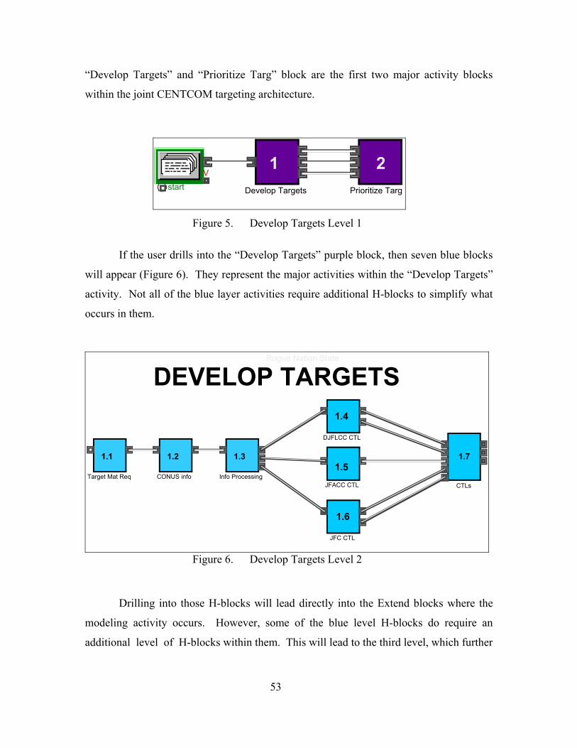
“Develop Targets” and “Prioritize Targ” block are the first two major activity blocks
within the joint CENTCOM targeting architecture.
start V
1Develop Targets
2Prioritize Targ
Figure 5. Develop Targets Level 1
If the user drills into the “Develop Targets” purple block, then seven blue blocks
will appear (Figure 6). They represent the major activities within the “Develop Targets”
activity. Not all of the blue layer activities require additional H-blocks to simplify what
occurs in them.
1.1
Target Mat Req
1.2
CONUS info
1.3
Info Processing
1.4
DJFLCC CTL
1.7
CTLs
1.5JFACC CTL
DEVELOP TARGETS
1.6
JFC CTL
Rogue Nation State
Figure 6. Develop Targets Level 2
Drilling into those H-blocks will lead directly into the Extend blocks where the
modeling activity occurs. However, some of the blue level H-blocks do require an
additional level of H-blocks within them. This will lead to the third level, which further
53
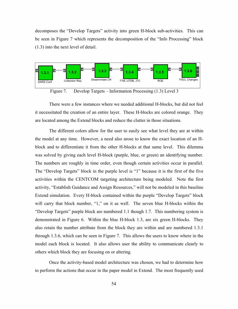
decomposes the “Develop Targets” activity into green H-block sub-activities. This can
be seen in Figure 7 which represents the decomposition of the “Info Processing” block
(1.3) into the next level of detail.
1.3.1
DARS Conf
1.3.2
Collection Req
1.3.3
Dissemintate CR
1.3.5
ROE
1.3.6
FSCL Changes
1.3.4
TTM, UTDB, JTC
Figure 7. Develop Targets – Information Processing (1.3) Level 3
There were a few instances where we needed additional H-blocks, but did not feel
it necessitated the creation of an entire layer. These H-blocks are colored orange. They
are located among the Extend blocks and reduce the clutter in those situations.
The different colors allow for the user to easily see what level they are at within
the model at any time. However, a need also arose to know the exact location of an H-
block and to differentiate it from the other H-blocks at that same level. This dilemma
was solved by giving each level H-block (purple, blue, or green) an identifying number.
The numbers are roughly in time order, even though certain activities occur in parallel.
The “Develop Targets” block in the purple level is “1” because it is the first of the five
activities within the CENTCOM targeting architecture being modeled. Note the first
activity, “Establish Guidance and Assign Resources,” will not be modeled in this baseline
Extend simulation. Every H-block contained within the purple “Develop Targets” block
will carry that block number, “1,” on it as well. The seven blue H-blocks within the
“Develop Targets” purple block are numbered 1.1 though 1.7. This numbering system is
demonstrated in Figure 6. Within the blue H-block 1.3, are six green H-blocks. They
also retain the number attribute from the block they are within and are numbered 1.3.1
through 1.3.6, which can be seen in Figure 7. This allows the users to know where in the
model each block is located. It also allows user the ability to communicate clearly to
others which block they are focusing on or altering.
Once the activity-based model architecture was chosen, we had to determine how
to perform the actions that occur in the paper model in Extend. The most frequently used
54
method was to develop a “throw away” model. A “throw away” model was a small
Extend model that could carry out a single function we were investigating. This method
allowed us to quickly see the limitations of the Extend software and develop methods to
bypass the shortfalls. With every idea that was proved to work in a “throw away” model,
we were better able to envision how the overall “Develop Targets” model would
function.
2. Cloning Items Several times throughout the Extend model, an organization will receive inputs
from several other organizations, process that information, and produce a new output to
be sent elsewhere. We desired items being sent through the model to have the ability to
retain individual attributes even after being batched. Our original thought was to activate
a new program block to send out new items whenever a new output was produced. This
makes sense to a user viewing the model because it is clear that one form of information
enters an organization, and a new item is produced. However, after building a few
“throw away” models, we discovered that attributes are lost if a program block is used.
We found a solution to this problem by using unbatch blocks. These blocks give
the user the ability to make multiple copies, or clones, of items that pass through it. What
sets the unbatch block apart from the program block is that cloned items retain their
attributes. For example, an item represents a message with an attribute for message size.
If this item were cloned using the unbatch block and disseminated to multiple
organization, the attribute for message size would be retained in each clone. However, if
a program generator were used in this same situation, the attribute of message size would
not transfer to the new items. While unbatch blocks are less visually intuitive to the user,
proper labeling will allow users to understand what they represent.
3. Standardized Model Procedures As model development progressed, there rose a need standardize the way several
aspects of the model were handled. First, we placed a FIFO Delay block immediately
before every Activity Delay block. The Extend software will display an error message if
an activity block currently processing one item is sent a second item. The FIFO Delay
55
blocks provide a location for items to wait until the Activity Delay block is ready for
them. Second, there are many instances where it is documented that an organization
receives a piece of information, but it is not documented what they do with that
information. Our solution was to send these items into an Exit block. This allows the
model to run without error, even with certain information essentially going to a dead end.
It also allows future users who discover a use for that information within that
organization to simply remove the exit and send the information where it is needed.
Third, information sent between organizations was often documented using more than
one communication path, such as voice and courier. For this situation, we set up a
hierarchy of communications. In the event of dual communications, the priority from
highest to lowest are Net Delay, Courier Delay, and Voice Delay. This hierarchy states a
network delay would take precedence over both the voice and courier delays, while the
courier delay would take precedence over the voice delay. This allows the model to
maintain a consistent interpretation of the paper model.
4. Model Database Inputs In order to enhance the flexibility of our model, we used a database to store
information regarding the values and distributions of attributes. A model without a
database can still function similarly, however, it is considered to be “hardwired.” This
means that in order to vary attributes, a user would have to dig down three or four levels
in the model. The analysis of the effects of changes on attributes, such as bandwidth and
process time, would be an extremely time consuming task for just the “Develop Targets”
portion of a hardwired model. Once the entire targeting process is represented, analysis
of a hardwired version would be too tedious for anyone to consider it a valuable tool.
To combat the problems associated with hardwiring such a large and variable
model, a database was created. This database contains several tables, which store the
values and distributions of all the attributes that can be altered throughout the model. In
an effort to best create tables that could handle the constantly evolving state of the model,
as future activities and delays are incorporated, it was decided to break down the tables so
that each one corresponded only to a numbered section of the model at level two. For
example, there are seven level two H-blocks in the “Develop Targets” activity (1.1
56
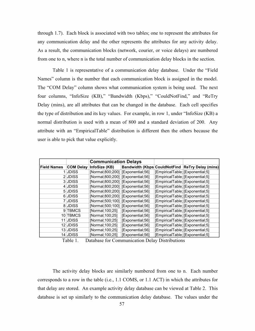
through 1.7). Each block is associated with two tables; one to represent the attributes for
any communication delay and the other represents the attributes for any activity delay.
As a result, the communication blocks (network, courier, or voice delays) are numbered
from one to n, where n is the total number of communication delay blocks in the section.
Table 1 is representative of a communication delay database. Under the “Field
Names” column is the number that each communication block is assigned in the model.
The “COM Delay” column shows what communication system is being used. The next
four columns, “InfoSize (KB),” “Bandwidth (Kbps),” “CouldNotFind,” and “ReTry
Delay (mins), are all attributes that can be changed in the database. Each cell specifies
the type of distribution and its key values. For example, in row 1, under “InfoSize (KB) a
normal distribution is used with a mean of 800 and a standard deviation of 200. Any
attribute with an “EmpiricalTable” distribution is different then the others because the
user is able to pick that value explicitly.
Communication DelaysField Names COM Delay InfoSize (KB) Bandwidth (Kbps)CouldNotFind ReTry Delay (mins)
1 JDISS [Normal;800;200] [Exponential;56] [EmpiricalTable; [Exponential;5]2 JDISS [Normal;800;200] [Exponential;56] [EmpiricalTable; [Exponential;5]3 JDISS [Normal;800;200] [Exponential;56] [EmpiricalTable; [Exponential;5]4 JDISS [Normal;800;200] [Exponential;56] [EmpiricalTable; [Exponential;5]5 JDISS [Normal;800;200] [Exponential;56] [EmpiricalTable; [Exponential;5]6 JDISS [Normal;800;200] [Exponential;56] [EmpiricalTable; [Exponential;5]7 JDISS [Normal;500;100] [Exponential;56] [EmpiricalTable; [Exponential;5]8 JDISS [Normal;500;100] [Exponential;56] [EmpiricalTable; [Exponential;5]9 TBMCS [Normal;100;25] [Exponential;56] [EmpiricalTable; [Exponential;5]
10 TBMCS [Normal;100;25] [Exponential;56] [EmpiricalTable; [Exponential;5]11 JDISS [Normal;100;25] [Exponential;56] [EmpiricalTable; [Exponential;5]12 JDISS [Normal;100;25] [Exponential;56] [EmpiricalTable; [Exponential;5]13 JDISS [Normal;100;25] [Exponential;56] [EmpiricalTable; [Exponential;5]14 JDISS [Normal;100;25] [Exponential;56] [EmpiricalTable; [Exponential;5]Table 1. Database for Communication Delay Distributions
The activity delay blocks are similarly numbered from one to n. Each number
corresponds to a row in the table (i.e., 1.1 COMS, or 1.1 ACT) in which the attributes for
that delay are stored. An example activity delay database can be viewed at Table 2. This
database is set up similarly to the communication delay database. The values under the 57
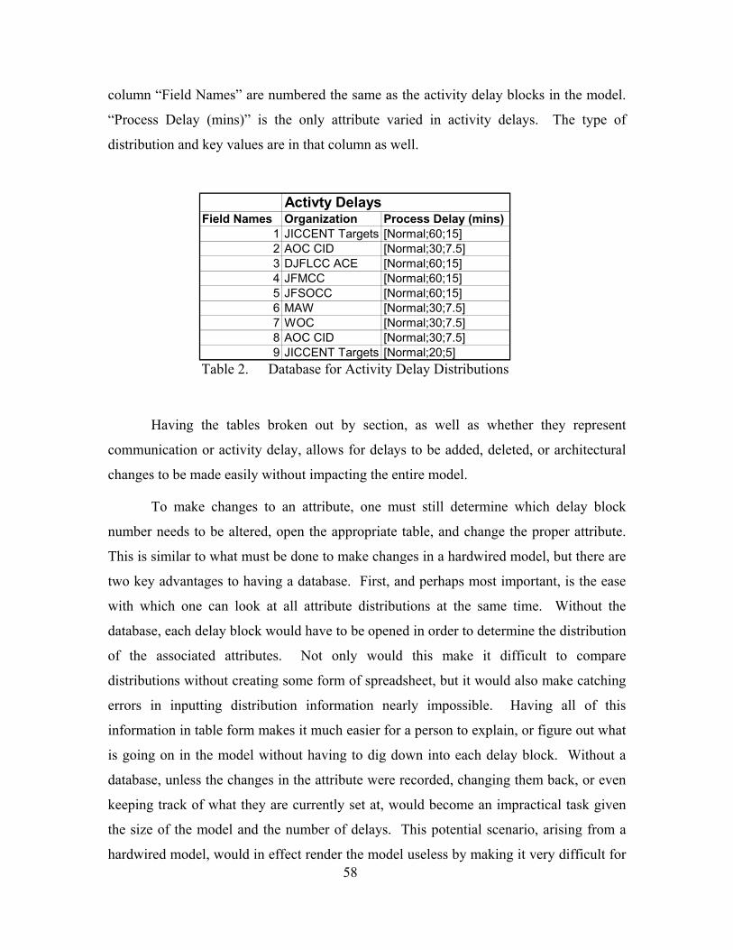
column “Field Names” are numbered the same as the activity delay blocks in the model.
“Process Delay (mins)” is the only attribute varied in activity delays. The type of
distribution and key values are in that column as well.
Table 2. Database for Activity Delay Distributions
aving the tables broken out by section, as well as whether they represent
commu
ine which delay block
numbe
hardwired model, would in effect render the model useless by making it very difficult for
Activty DelaysField Names Organization Process Delay (mins)
1 JICCENT Targets [Normal;60;15]2 AOC CID [Normal;30;7.5]3 DJFLCC ACE [Normal;60;15]4 JFMCC [Normal;60;15]5 JFSOCC [Normal;60;15]6 MAW [Normal;30;7.5]7 WOC [Normal;30;7.5]8 AOC CID [Normal;30;7.5]9 JICCENT Targets [Normal;20;5]
H
nication or activity delay, allows for delays to be added, deleted, or architectural
changes to be made easily without impacting the entire model.
To make changes to an attribute, one must still determ
r needs to be altered, open the appropriate table, and change the proper attribute.
This is similar to what must be done to make changes in a hardwired model, but there are
two key advantages to having a database. First, and perhaps most important, is the ease
with which one can look at all attribute distributions at the same time. Without the
database, each delay block would have to be opened in order to determine the distribution
of the associated attributes. Not only would this make it difficult to compare
distributions without creating some form of spreadsheet, but it would also make catching
errors in inputting distribution information nearly impossible. Having all of this
information in table form makes it much easier for a person to explain, or figure out what
is going on in the model without having to dig down into each delay block. Without a
database, unless the changes in the attribute were recorded, changing them back, or even
keeping track of what they are currently set at, would become an impractical task given
the size of the model and the number of delays. This potential scenario, arising from a
58
a person to use it as a tool to analyze how changes may affect the process. Secondly,
once a person becomes familiar with the numbering system, changes to these
distributions can be made extremely quickly and easily so the effect of changes to
attributes can be studied.
The only change that had to be made going from the initial “hardwired” model to
the final database oriented model involved the units of time that were tracked throughout
the pro
entered into the table as a distribution around a mean measured
in Kbp
onality of a database. Each delay is represented by its own
record,
” field from all the tables thereby deleting the string variable
name r
cess. Initially, seconds were the global time unit for the model; however, the
smallest global time unit that a database is compatible with is minutes. Since ultimately
the length of the process that is being analyzed is on the order of a few days, it was
decided that reporting delay times in minutes rather than seconds would not have much of
an effect on the results.
Certain attributes are still input with respect to seconds. An example of this is
link bandwidth, which is
s. The delay block itself has been modified to account for the fact that the model
is working in minutes.
One item to be addressed is a glitch associated with the Extend software when
implementing the functi
one through n, within the table. If more than one delay has the same name, which
is not uncommon given the nature of this model (i.e., multiple JDISS communications
delays could be present in a single section), all the parameters for the attribute will be
drawn from the set of parameters defined in the record representing the first delay with
the identical string name.
Three methods of combating this problem were devised. The first would involve
eliminating the “delay type
epresentative of the type of communication or activity delay from the table. This
option was not pursued due to the fact it would require the user to look at the table in
conjunction with the model to make any changes to specific blocks, since only a number,
as opposed to a number and a name, would now represent these blocks. A second
workaround would involve renaming the string variable that represents each delay so that
they are all unique. For example there could be JDISS 1, JDISS 2, JDISS 3, and so on.
59
A final method to solve this issue would involve connecting a constant block to the
“input record” value on the database lookup block. This constant block would be
configured to correspond with the record number that should be looked up.
Although very similar to the second method, the latter procedure was selected for
the following two reasons. First, it makes it slightly easier for the user to check for input
errors w
everting back to the record of the first delay with that exact
name i
XTEND BLOCKS
he architecture, colors, numbers, standard procedures, and databases all help to
g in the model. However, all of the modeling actions
are bei
ithin the model. Since the constant block sits one level higher than the internal
section of the database lookup block, it is quicker to ensure that data is being pulled from
the correct record in the table. The constant value being input is displayed on the block
itself. The second reason has to do with model flexibility. If delays were added, deleted
or rearranged, it is easier to modify the numbers in the constant blocks than to rename all
the delays in the table itself.
Even after incorporating the constant block, the database lookup block itself still
indicated that the record was r
n the table. However, using information blocks to identify what values for the
attributes were actually being assigned, we determined that the appropriate record and
corresponding distribution was being associated with the item each time the model was
run.
B. E
T
better understand what is occurrin
ng performed by blocks from the Extend libraries. With a few exceptions, this
model uses a small number of Extend blocks to accomplish the accurate modeling of the
“Develop Targets” activity. The blocks most frequently used are:
• Activity Delay
• Batch
• Batch (10)
• Catch
• DB Lookup
• Exit
• Get Attribute
60
• Input Random Number
Output
tput (5)
(Variable)
e fo will describe each of these commonly used Extend
locks in greater detail.
olds an item for a specified amount of delay time, then releases it. The delay
time is onnected, the value at the D connector when the item
is rece
llows items from several sources to be joined as a single item. This is useful for
synchronizing resources and combining various parts of a job. In the dialog, you specify
the num
llows items from up to ten sources to be joined into a single item. More than one
item m ut before an output is created. In the dialog, you specify
the number of items from each of the inputs that is required to produce each output item.
• Program
• Queue FIFO
• Select DE
• Select DE Ou
• Set Attribute
• Throw
• Unbatch
• Unbatch
Th llowing 16 sections
b
1. Activity Delay H
the value in the dialog or, if c
ived (Extend v6 A59). Most of the activity delay blocks throughout the model
receive either exponentially or normally distributed delay times via a DB Lookup block.
2. Batch A
ber of items from each of the inputs that is required to produce one output item.
You can also specify that items at one or more inputs will not be brought into the block
until one or more of the other inputs has its requirements filled (Extend v6 A61). The
primary use of this block is to collect different inputs at a single organization before that
organization processes the information and produces a new item.
3. Batch (10) A
ay be required at each inp
61
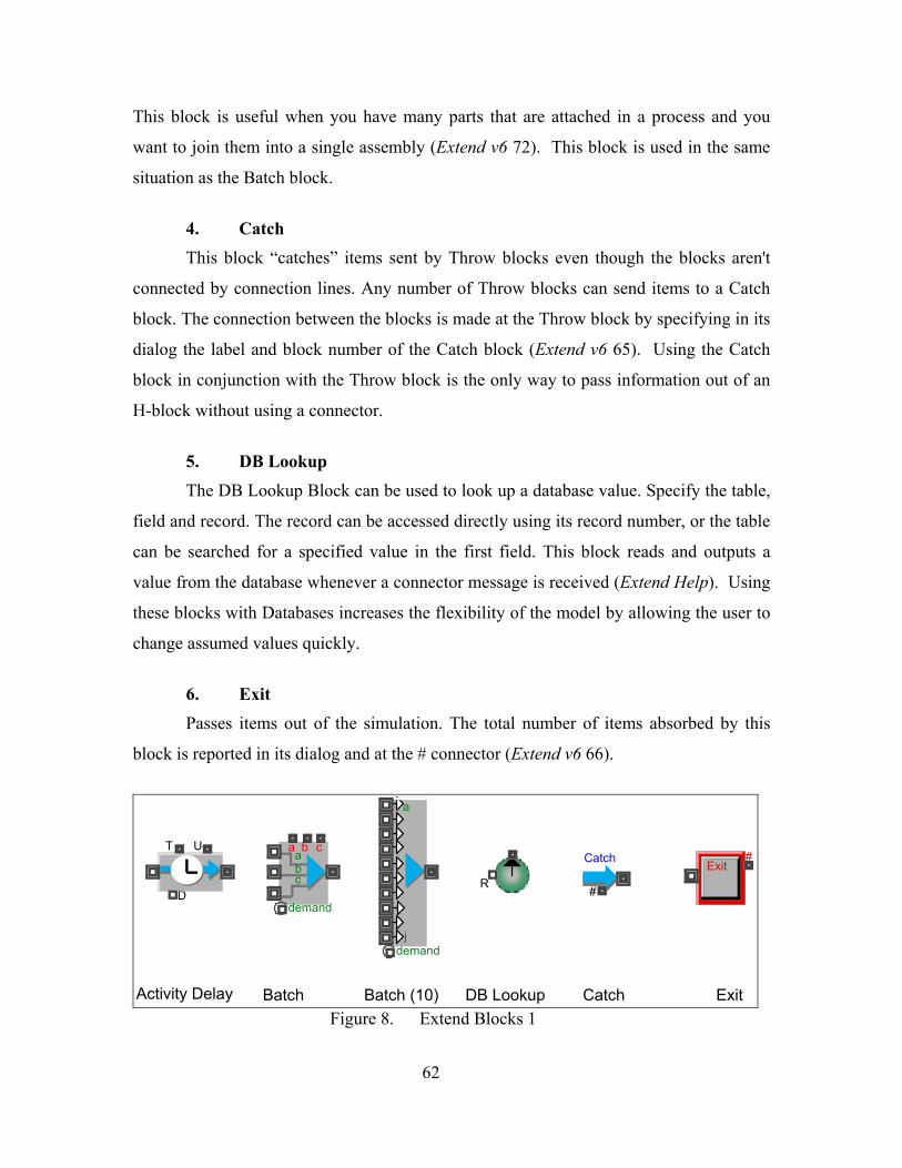
This bl
items sent by Throw blocks even though the blocks aren't
connected by connection lines. Any number of Throw blocks can send items to a Catch
block. The connection between the blocks is made at the Throw block by specifying in its
dialog
e used to look up a database value. Specify the table,
field and record. The record can be accessed directly using its record number, or the table
can be value in the first field. This block reads and outputs a
value f
ulation. The total number of items absorbed by this
block is reported in its dialog and at the # connector (Extend v6 66).
ock is useful when you have many parts that are attached in a process and you
want to join them into a single assembly (Extend v6 72). This block is used in the same
situation as the Batch block.
4. Catch This block “catches”
the label and block number of the Catch block (Extend v6 65). Using the Catch
block in conjunction with the Throw block is the only way to pass information out of an
H-block without using a connector.
5. DB Lookup The DB Lookup Block can b
searched for a specified
rom the database whenever a connector message is received (Extend Help). Using
these blocks with Databases increases the flexibility of the model by allowing the user to
change assumed values quickly.
6. Exit Passes items out of the sim
Ddemand
bc
demandj
Catch
#
Exit#
Activity Delay Batch Batch (10) Catch Exit
R
DB Lookup Figure 8. Extend Blocks 1
T U a b ca
a
62
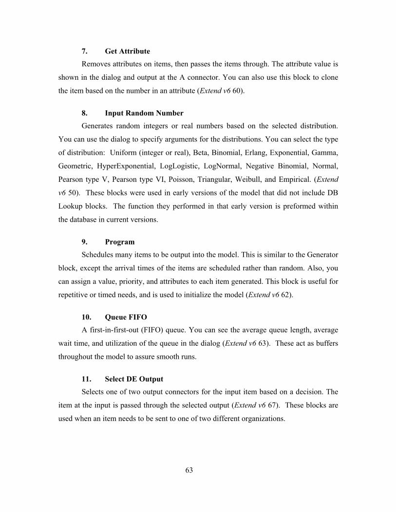
7. Get Attribute
Removes attributes on items, then passes the items through. The attribute value is
shown in the dialog and output at the A connector. You can also use this block to clone
the item based on the number in an attribute (Extend v6 60).
8. Input Random Number Generates random integers or real numbers based on the selected distribution.
You can use the dialog to specify argum utions. You can select the ty
of distribution: Uniform (integer or real), Beta, Binomial, Erlang, Exponential, Gamma,
Geometric, HyperExponential, LogLogistic, LogNormal, Negative Binomial, Normal,
Pearson
ersion is preformed within
the data e in
queue. You can see the average queue length, average
wait time, and utilization of the queue in the dialog (Extend v6 63). These act as buffers
through smooth runs.
e blocks are
used when an item needs to be sent to one of two different organizations.
ents for the distrib pe
type V, Pearson type VI, Poisson, Triangular, Weibull, and Empirical. (Extend
v6 50). These blocks were used in early versions of the model that did not include DB
Lookup blocks. The function they performed in that early v
bas current versions.
9. Program
Schedules many items to be output into the model. This is similar to the Generator
block, except the arrival times of the items are scheduled rather than random. Also, you
can assign a value, priority, and attributes to each item generated. This block is useful for
repetitive or timed needs, and is used to initialize the model (Extend v6 62).
10. Queue FIFO A first-in-first-out (FIFO)
out the model to assure
11. Select DE Output Selects one of two output connectors for the input item based on a decision. The
item at the input is passed through the selected output (Extend v6 67). Thes
63
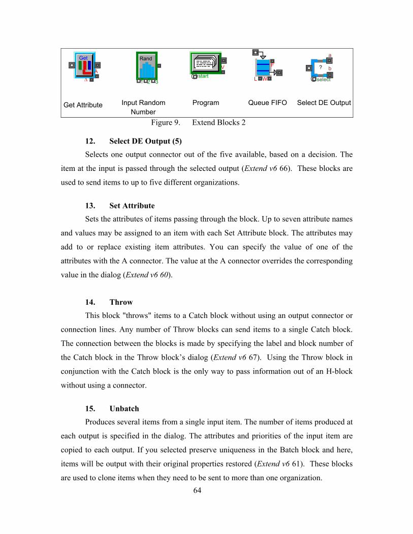
G Rand
L W select
Get Attribute Program Queue FIFO Select DE Output
A∆
et
1 2 3start
V Fb?
a
Input Random Number
Figure 9. Extend Blocks 2 12. Select DE Output (5) Selects one output connector out of the five available, based on a decision. The
item at the input is passed through the selected output (Extend v6 66). These blocks are
used to send items to up to five different organizations.
13. Set Attribute
Sets the attributes of items passing through the block. Up to seven attribute names
and values may be assigned to an item ibute block. The attributes may
add to or replace existing item attributes. You can specify the value of one of the
attribut ith lue at the A connector overrides the corresponding
value i
his block "throws" items to a Catch block without using an output connector or
connec
5. Unbatch
ms from a single input item. The number of items produced at
each o
with each Set Attr
es w the A connector. The va
n the dialog (Extend v6 60).
14. Throw
T
tion lines. Any number of Throw blocks can send items to a single Catch block.
The connection between the blocks is made by specifying the label and block number of
the Catch block in the Throw block’s dialog (Extend v6 67). Using the Throw block in
conjunction with the Catch block is the only way to pass information out of an H-block
without using a connector.
1
Produces several ite
utput is specified in the dialog. The attributes and priorities of the input item are
copied to each output. If you selected preserve uniqueness in the Batch block and here,
items will be output with their original properties restored (Extend v6 61). These blocks
are used to clone items when they need to be sent to more than one organization. 64
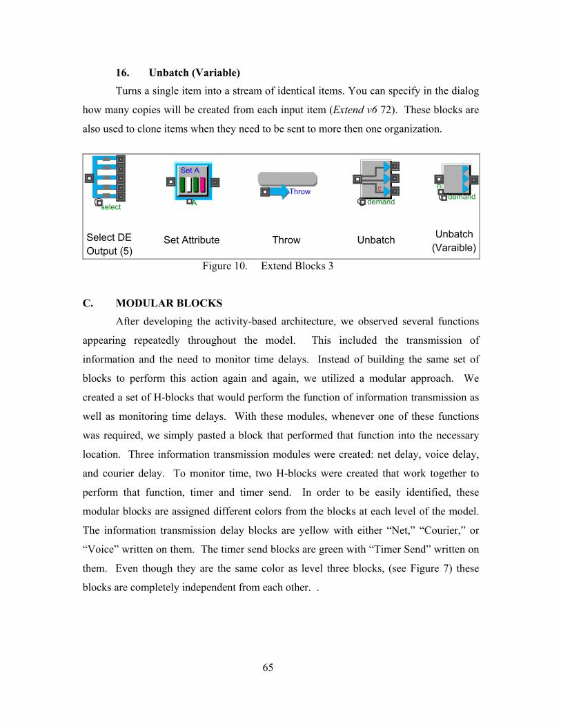
16. Unbatch (Variable)
Turns a single item into a stream of identical items. You can specify in the dialog
how m opies will be created from each input item (Extend v6 72). These blocks are
also us they need to be sent to more then one organization.
any c
ed to clone items when
AThrow
demand
a
bn
demand
Var
SelectOutpu
select
Set A
c
Unbatch Throw Unbatch
DE Set Attributet (5) (Varaible)
Figure 10. Extend Blocks 3
C. MODULAR BLOCKS After developing the activity-based architecture, we observed several functions
appearing repeatedly throughout the model. This included the transmission of
information and the need to monitor time delays. Instead of building the same set of
blocks to perform this action again and again, we utilized a modular approach. We
created a set of H-blocks that would perform the function of information transmission as
well as monitoring time delays. With these modules, whenever one of these functions
was required, we simply p hat function into the necessary
location. Three information transmission modules were created: net delay, voice delay,
ocks were created that work together to
perform
asted a block that performed t
and courier delay. To monitor time, two H-bl
that function, timer and timer send. In order to be easily identified, these
modular blocks are assigned different colors from the blocks at each level of the model.
The information transmission delay blocks are yellow with either “Net,” “Courier,” or
“Voice” written on them. The timer send blocks are green with “Timer Send” written on
them. Even though they are the same color as level three blocks, (see Figure 7) these
blocks are completely independent from each other. .
65
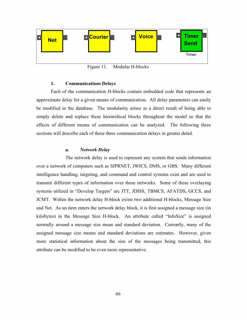
TimerVoiceNet Send
Timer
Courier
Figure 11. Modular H-blocks
. Communications Delays
Each of the communication H-blocks contain embedded code that represents an
approximate delay for a given means of communication. All delay parameters can easily
be modified in the database. The modularity arises as a direct result of being able to
simply delete and replace these hierarchical blocks throughout the model so that the
effects of different mean alyzed. The following three
sections will describe each of these three communication delays in greater detail.
S, and
JCMT. Within the network delay H-block exists two additional H-blocks, Message Size
and Net. As a y block, it is first assigned a message size (in
kilobytes) in
1
s of communication can be an
a. Network Delay The network delay is used to represent any system that sends information
over a network of computers such as SIPRNET, JWICS, DMS, or GBS. Many different
intelligence handling, targeting, and command and control systems exist and are used to
transmit different types of information over these networks. Some of these overlaying
systems utilized in “Develop Targets” are JTT, JDISS, TBMCS, AFATDS, GCC
n item enters the network dela
the Message Size H-block. An attribute called “InfoSize” is assigned
normally around a message size mean and standard deviation. Currently, many of the
assigned message size means and standard deviations are estimates. However, given
more statistical information about the size of the messages being transmitted, this
attribute can be modified to be even more representative.
66
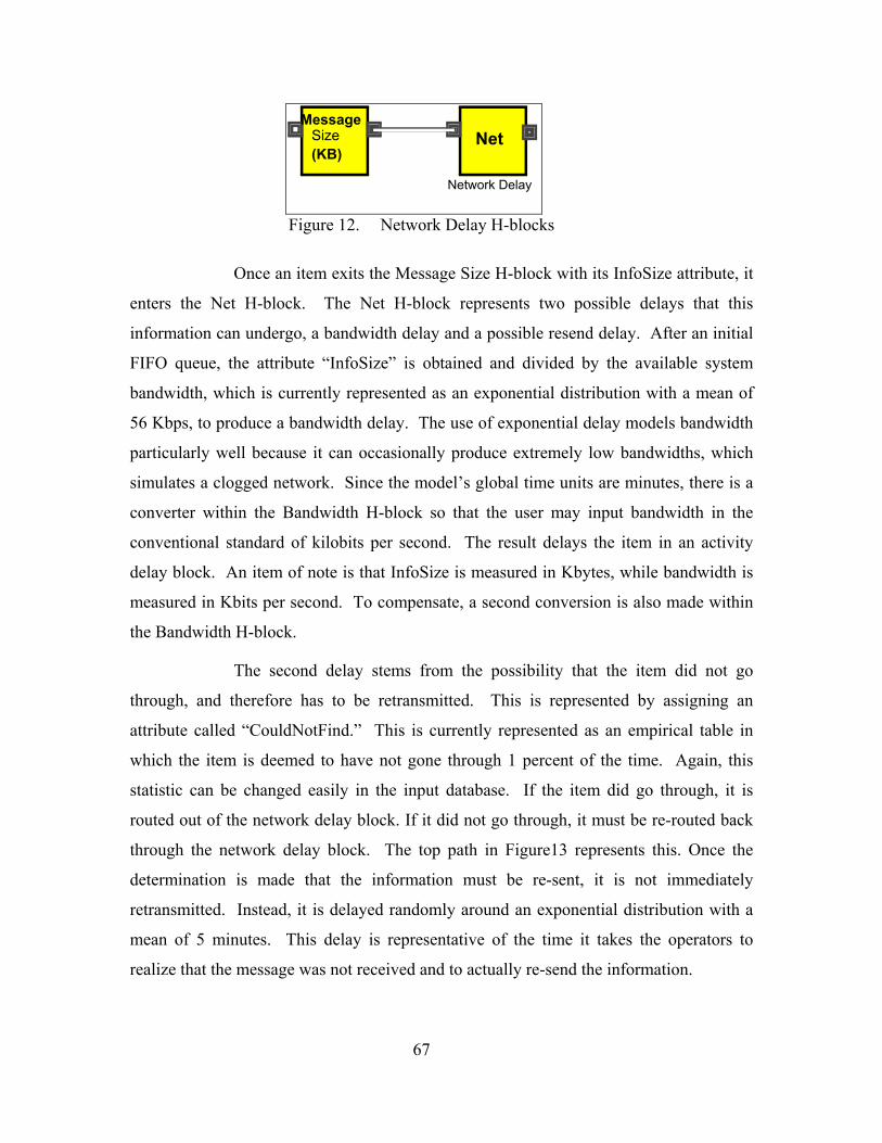
Net
Network Delay
MessageSize(KB)
Figure 12. Network Delay H-blocks
Once an item exits the Message Size H-block with its InfoSize attribute, it
enters the Net H-block. The Net H-block represents two possible delays that this
information can under send delay. After an initial
FIFO queue, the attribute “InfoSize” is obtained and divided by the available system
bandwidth, wh
tFind.” This is currently represented as an empirical table in
which the item is deemed to have not gone through 1 percent of the time. Again, this
statistic can be
go, a bandwidth delay and a possible re
ich is currently represented as an exponential distribution with a mean of
56 Kbps, to produce a bandwidth delay. The use of exponential delay models bandwidth
particularly well because it can occasionally produce extremely low bandwidths, which
simulates a clogged network. Since the model’s global time units are minutes, there is a
converter within the Bandwidth H-block so that the user may input bandwidth in the
conventional standard of kilobits per second. The result delays the item in an activity
delay block. An item of note is that InfoSize is measured in Kbytes, while bandwidth is
measured in Kbits per second. To compensate, a second conversion is also made within
the Bandwidth H-block.
The second delay stems from the possibility that the item did not go
through, and therefore has to be retransmitted. This is represented by assigning an
attribute called “CouldNo
changed easily in the input database. If the item did go through, it is
routed out of the network delay block. If it did not go through, it must be re-routed back
through the network delay block. The top path in Figure13 represents this. Once the
determination is made that the information must be re-sent, it is not immediately
retransmitted. Instead, it is delayed randomly around an exponential distribution with a
mean of 5 minutes. This delay is representative of the time it takes the operators to
realize that the message was not received and to actually re-send the information.
67

F
L W
0
D
T U
Delay time
A∆
Get
Info SizeCon2OutCon2Out
BW
Bandwidth
A
Set A
1 2 3
Rand
Con1InCon1In
A∆
Get
select
b?
a
Could not find
F
L W
0
a
b
Set the CouldNotFind variable to 0.01.
D
T U
Delay time
1 2 3
Rand
F
L W
0
If the information does not reach it desired location, it is exponentially delayed before it is re-transmitted.
(Seconds)
F
L W
0
Network Delay
Figure 13. Extend Blocks Inside Net H-block
b. Courier Delay Th rmation exchange that
requires a pers mation from one place to another. Within a
Courier Delay
e courier delay block is used to represent any info
on to physically walk infor
H-block there exist two additional H-blocks: a Dist. Walked H-block and
Courier H-Block. As the item enters the Dist. Walked block it is assigned an attribute
called “Distance,” which represents the distance, in feet, that the person must walk to
deliver the information. In the real world, there are different distances a courier must
walk to deliver his information depending on each particular situation. However, in this
model, it is assumed the distance a courier must walk is exponentially distributed with a
mean of 300 feet.
Dist.
Walked(ft)
Courier
Courier Delay
Figure 14. Courier Delay H-block
Once “D Courier H-block and can
encounter a m mum of three different delays. The item goes immediately into a FIFO
queue to preve
istance” is set, this item enters the
axi
nt it from being lost if the courier delay block is currently busy. If the
system is not busy, the item will enter its first delay, at an activity delay block in which it
is delayed by an amount of time equal to the distance in feet that must be traveled divided
by a random walking speed. The random walking speed is represented as a normal
68
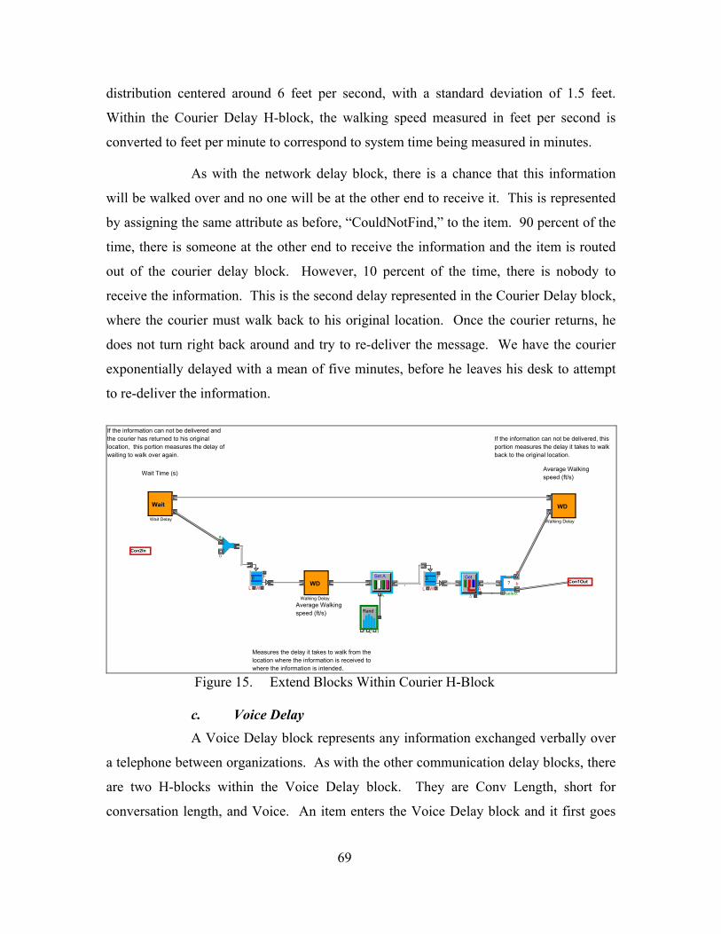
distribution centered around 6 feet per second, with a standard deviation of 1.5 feet.
Within the Courier Delay H-block, the walking speed measured in feet per second is
converted to feet per minute to correspond to system time being measured in minutes.
As with the network delay block, there is a chance that this information
will be walked over and no one will be at the other end to receive it. This is represented
by assigning the same attribute as before, “CouldNotFind,” to the item. 90 percent of the
time, there is someone at the other end to receive the information and the item is routed
out of the courier delay block. However, 10 percent of the time, there is nobody to
receive the information. This is the second delay represented in the Courier Delay block,
where the courier must walk back to his original location. Once the courier returns, he
does not turn right back around and try to re-deliver the message. We have the courier
exponentially delayed with a mean of five minutes, before he leaves his desk to attempt
to re-deliver the information.
the courier has returned to his original location, this portion measures the delay of
F
L W
0
WD
Walking Delay
Wait
Wait Delay
WD
Walking DelayAverage Walking speed (ft/s)
Average Walking speed (ft/s)
Measures the delay it takes to walk from the location where the information is received to where the information is intended.
If the information can not be delivered, this portion measures the delay it takes to walk back to the original location.
A
Set A
1 2 3
Rand
A∆
GetF
L W
0
select
b?
a
If the information can not be delivered and
waiting to walk over again.
Wait Time (s)
a
b
Con1OutCon1Out
Con2InCon2In
Figure 15. Extend Blocks Within Courier H-Block
c. Voice Delay
anged verbally over
a telephone be ith the other communication delay blocks, there
are two H-blo
A Voice Delay block represents any information exch
tween organizations. As w
cks within the Voice Delay block. They are Conv Length, short for
conversation length, and Voice. An item enters the Voice Delay block and it first goes
69
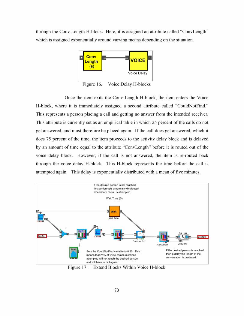
through the Conv Length H-block. Here, it is assigned an attribute called “ConvLength”
which is assigned exponentially around varying means depending on the situation.
ConvLength
(s)VOICE
Voice Delay
Figure 16. Voice Delay H-blocks
Once the item exits the Conv Length H-block, the item enters the Voice
H-block, wher
e it is immediately assigned a second attribute called “CouldNotFind.”
This represents a person placing a call and getting no answer from the intended receiver.
This attribute is currently set as an empirical table in which 25 percent of the calls do not
get answered, and must therefore be placed again. If the call does get answered, which it
does 75 percent of the time, the item proceeds to the activity delay block and is delayed
by an amount of time equal to the attribute “ConvLength” before it is routed out of the
voice delay block. However, if the call is not answered, the item is re-routed back
through the voice delay H-block. This H-block represents the time before the call is
attempted again. This delay is exponentially distributed with a mean of five minutes.
Sets the CouldNotFind variable to 0.25. This means that 25% of voice communications attempted will not reach the desired person and will have to call again.
D
T U
Delay time
A∆
Get
ConvLength
A
Set A
1 2 3
Rand
A∆
Get
If the desired person is not reached, this portion sets a normally distributed time before re-call is attempted.
Wait Time (S)
select
b?
a
Could not find
a
b
Wait
Wait Delay
F
L W
0
If the desired person is reached, then a delay the length of the conversation is produced.
F
L W
0
Con1OutCon1OutCon2InCon2In
Figure 17. Extend Blocks Within Voice H-block
70
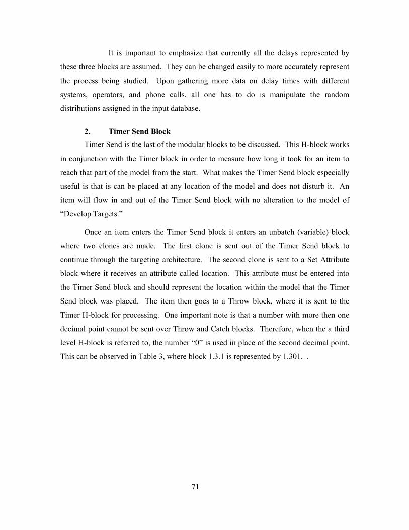
It is important to emphasize that currently all the delays represented by
these three blocks are assumed. They can be changed easily to more accurately represent
the process being studied. Upon gathering more data on delay times with different
systems, operators, and phone calls, all one has to do is manipulate the random
distributions assigned in the input database.
2. Timer Send Block Timer Send is the last of the modular blocks to be discussed. This H-block works
in conjunction with the Timer block in order to measure how long it took for an item to
reach that part of the model from the start. What makes the Timer Send block especially
useful is that is can be placed at any location of the model and does not disturb it. An
item will flow in and out of the Timer Send block with no alteration to the model of
“Develop Targets.”
Once an item enters the Timer Send block it enters an unbatch (variable) block
where two clones are made. The first clone is sent out of the Timer Send block to
continue through the targeting architecture. The second clone is sent to a Set Attribute
block where it receives an attribute called location. This attribute must be entered into
the Timer Send block and should represent the location within the model that the Timer
Send block was placed. The item then goes to a Throw block, where it is sent to the
Timer H-block for processing. One important note is that a number with more then one
decimal point cannot be sent over Throw and Catch blocks. Therefore, when the a third
level H-block is referred to, the number “0” is used in place of the second decimal point.
This can be observed in Table 3, where block 1.3.1 is represented by 1.301. .
71
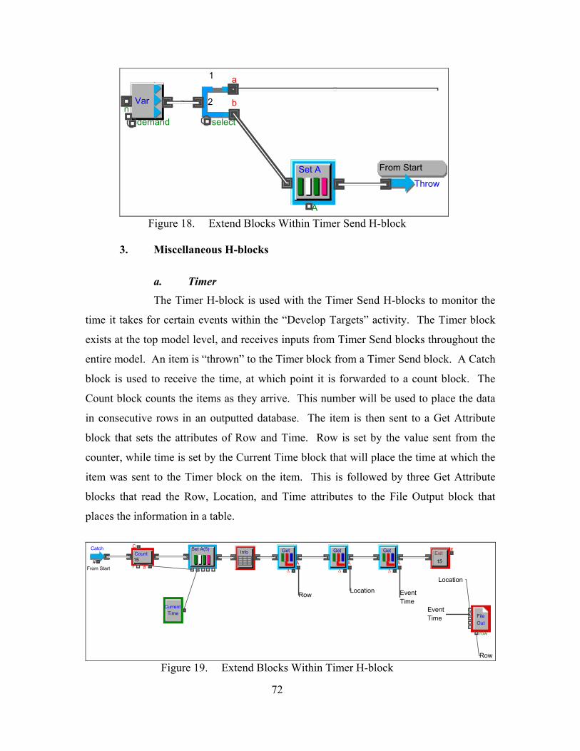
ndemand
Var
select
b?
a
2
1
Throw
From Start
A
Set A
Figure 18. Extend Blocks Within Timer Send H-block
3. Miscellaneous H-blocks
a. Timer The Timer H-block is used with the Timer Send H-blocks to monitor the
time it takes for certain events within the “Develop Targets” activity. The Timer block
exists at the top model level, and receives inputs from Timer Send blocks throughout the
entire model. An item is “thrown” to the Timer block from a Timer Send block. A Catch
block is used to receive the time, at which point it is forwarded to a count block. The
Count block counts the items as they arrive. This number will be used to place the data
in consecutive rows in an outputted database. The item is then sent to a Get Attribute
block that sets the attributes of Row and Time. Row is set by the value sent from the
counter, while time is set by the Current Time block that will place the time at which the
item was sent to the Timer block on the item. This is followed by three Get Attribute
blocks that read the Row, Location, and Time attributes to the File Output block that
places the information in a table.
row
FileOut
Exit#
15
Catch
#From Start
Count
#15
CurrentTime
A∆
Get
EventTime
Set A(5)
A∆
Get
A∆
GetInfo
Row
Row
Location
Location
EventTime
C
r
Figure 19. Extend Blocks Within Timer H-block
72
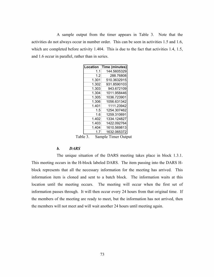
A sample output from the timer appears in Table 3. Note that the
activities do not always occur in number order. This can be seen in activities 1.5 and 1.6,
which are completed before activity 1.404. This is due to the fact that activities 1.4, 1.5,
and 1.6 occur in parallel, rather than in series.
Location Time (minutes)1.1 144.56053291.2 288.76808
1.301 510.36329151.302 931.85901031.303 943.6721091.304 1011.9584461.305 1036.7239011.306 1056.6313421.401 1111.23942
1.5 1254.3074621.6 1259.310691
1.402 1334.1248271.403 1422.0927641.404 1610.569813
1.7 1632.065372Table 3. Sample Timer Output
b. DARS The unique situation of the DARS meeting takes place in block 1.3.1.
This meeting occurs in the H-block labeled DARS. The item passing into the DARS H-
block represents that all the necessary information for the meeting has arrived. This
information item is cloned and sent to a batch block. The information waits at this
location until the meeting occurs. The meeting will occur when the first set of
information passes through. It will then occur every 24 hours from that original time. If
the members of the meeting are ready to meet, but the information has not arrived, then
the members will not meet and will wait another 24 hours until meeting again.
73
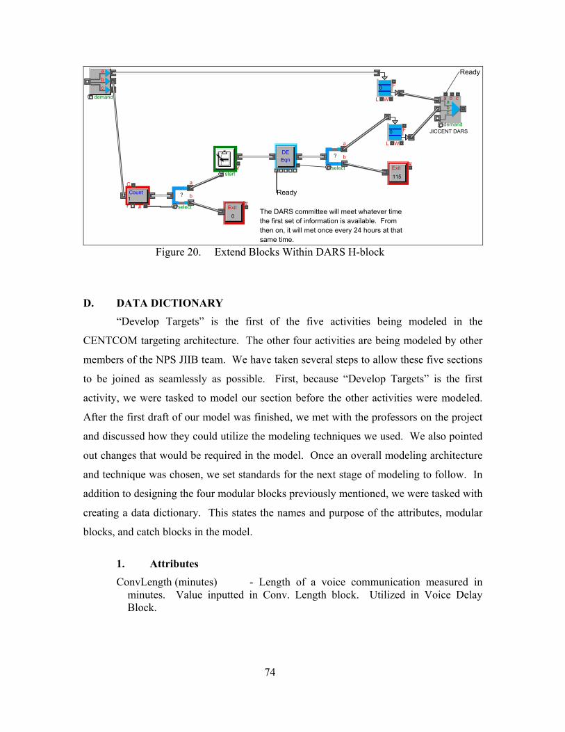
demand
a b cabc
JICCENT DARS
F
L W
0
F
L W
0
demand
abc
DEEqn
startV
The DARS committee will meet whatever time the first set of information is available. From then on, it will met once every 24 hours at that same time.
Ready
Ready
select
b?
a
Exit#
115
Count
#1
select
b?
a
Exit#
0
C
r
Figure 20. Extend Blocks Within DARS H-block
D. DATA DICTIONARY
“Develop Targets” is the first of the five activities being modeled in the
CENTCOM targeting architecture. The other four activities are being modeled by other
members of the NPS JIIB team. We have taken several steps to allow these five sections
to be joined as seamlessly as possible. First, because “Develop Targets” is the first
activity, we were tasked to model our section before the other activities were modeled.
After the first draft of our model was finished, we met with the professors on the project
and discussed how they could utilize the modeling techniques we used. We also pointed
out changes that would be required in the model. Once an overall modeling architecture
and technique was chosen, we set standards for the next stage of modeling to follow. In
addition to designing the four modular blocks previously mentioned, we were tasked with
creating a data dictionary. This states the names and purpose of the attributes, modular
blocks, and catch blocks in the model.
1. Attributes ConvLength (minutes) - Length of a voice communication measured in
minutes. Value inputted in Conv. Length block. Utilized in Voice Delay Block.
74
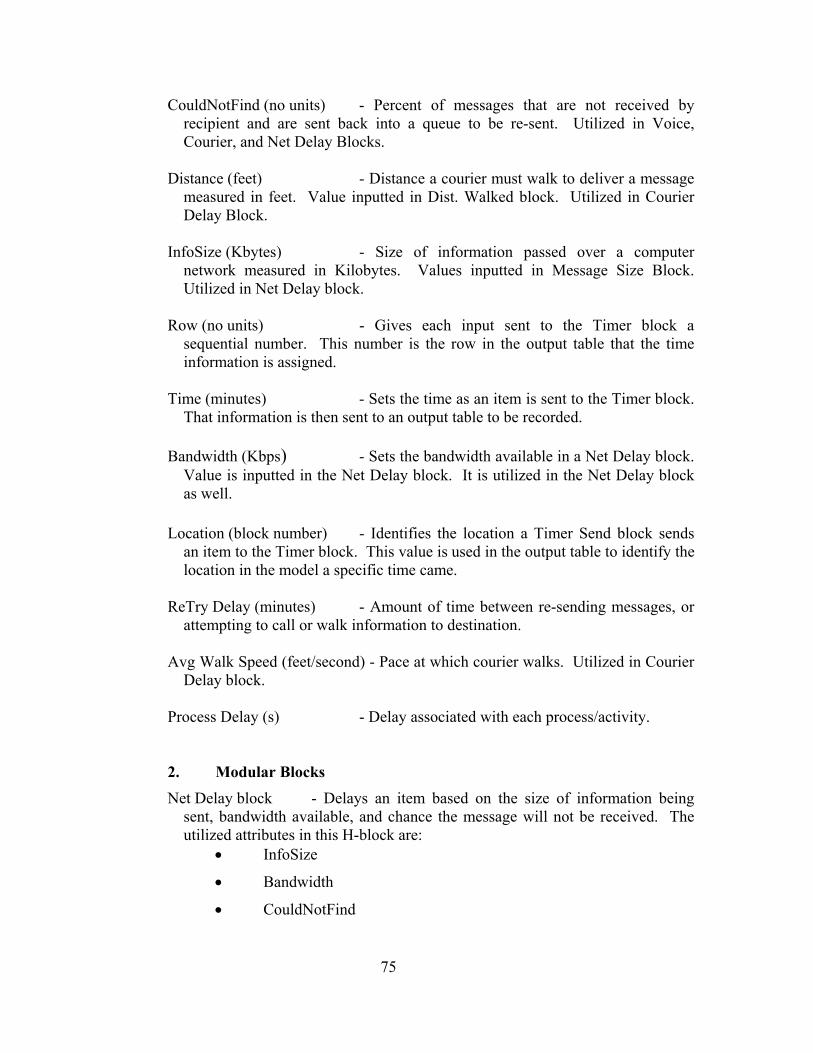
CouldNotFind (no units) - Percent of messages that are not received by recipient and are sent back into a queue to be re-sent. Utilized in Voice, Courier, and Net Delay Blocks.
Distance (feet) - Distance a courier must walk to deliver a message
measured in feet. Value inputted in Dist. Walked block. Utilized in Courier Delay Block.
InfoSize (Kbytes) - Size of information passed over a computer
network measured in Kilobytes. Values inputted in Message Size Block. Utilized in Net Delay block.
Row (no units) - Gives each input sent to the Timer block a
sequential number. This number is the row in the output table that the time information is assigned.
Time (minutes) - Sets the time as an item is sent to the Timer block.
That information is then sent to an output table to be recorded. Bandwidth (Kbps) - Sets the bandwidth available in a Net Delay block.
Value is inputted in the Net Delay block. It is utilized in the Net Delay block as well.
Location (block number) - Identifies the location a Timer Send block sends
an item to the Timer block. This value is used in the output table to identify the location in the model a specific time came.
ReTry Delay (minutes) - Amount of time between re-sending messages, or
attempting to call or walk information to destination. Avg Walk Speed (feet/second) - Pace at which courier walks. Utilized in Courier
Delay block. Process Delay (s) - Delay associated with each process/activity. 2. Modular Blocks
Net Delay block - Delays an item based on the size of information being sent, bandwidth available, and chance the message will not be received. The utilized attributes in this H-block are:
• InfoSize
• Bandwidth
• CouldNotFind
75
Courier Delay block - Delays an item based on the distance a courier must walk to deliver a message, and the chance the message will not be received. The utilized attributes in this H-block are:
• Distance
• CouldNotFind
Voice Delay block - Delays an item based on the length of the conversation
needed to transmit the necessary information, and the chance the call will not be answered. The utilized attributes in this H-block are:
• ConvLength
• CouldNotFind
Timer Send - Sends an item to the Timer block to record the time at
which the item passed through the Timer Send block. The utilized attributes in this H-block are:
• Location
3. Names of Catch Blocks Catch blocks have a label (name) and catch items from a “Catch Group.” Throw
blocks throw items to a Catch Group and also to a specific catch block by label.
Therefore, you can send many different items to different locations using a Catch Group,
but the “Catch block label” must be unique. The Catch Groups utilized in the “Develop
Targets” activity are:
• MP&BFs
• ROE
• Target Database
• Timer
• WMD Targets
The following are unique Catch block labels used in the “Develop Targets” activity. In
parentheses is the Catch Group to which the Catch block label belongs.
• From Start (Timer)
• WMD (WMD Targets)
• Maps & Plots (MP&BFs)
• Maps & Plots 2 (MP&BFs)
76

• Target Database (Target Database)
• ROE (ROE)
77

THIS PAGE INTENTIONALLY LEFT BLANK
78
VI. RESULTS AND CONCLUSIONS
A. IMPORTANCE OF EXTEND MODEL The development of this Extend model was important for two primary reasons.
The first is it will serve as a useful foundation from which the other four activities can be
modeled in order to represent the entire targeting cycle. The second is it demonstrates the
ability of the model to track one of the key metrics, time to complete certain tasks within
the cycle.
Creating the Extend model for the “Develop Targets” activity prior to modeling
any of the other five activities will save the NPS JIIB group valuable time in the long run.
Given the parallel effort of several activities being modeled simultaneously by different
people, it is likely that had the effort commenced at the same time, many similar
problems would have been encountered. By generating the “Develop Targets” activity
roughly two weeks prior to the development of models for the other activities, many
ways to work-around certain problems were discovered and briefed to the rest of the NPS
JIIB group. Many of these issues have been mentioned in the previous chapter, such as
whether or not to implement a database, and, once implemented, how to effectively use it.
Ultimately, this baseline model for the “Develop Targets” activity will serve as a valuable
skeleton for the development of the overall model of CENTCOM’s targeting architecture.
The principle metric tracked by this model is the elapsed time, in minutes. Since
this Extend model was developed in an activity-oriented manner, the “Develop Targets”
activity was broken down into seven major sub-activities (1.1 through 1.7). By
developing a timer block to stamp an item with the current time and throw this value to a
table, it is very easy to keep track of the average time it takes to complete any process.
As the model is currently configured, this table lists the cumulative time from when the
process started to when each major sub-activity was completed. If the user wants to
know how much time elapsed during activity 1.3, the cumulative time associated with 1.3
in the output table must be subtracted from the cumulative time associated with 1.2 in the
same table. Furthermore, the flexibility of the model will allow for Extend’s standard
79
Timer blocks to be placed anywhere in the model. These blocks will measure the amount
of time it takes an item to get from any point A to any point B.
The advantage of being able to track time to complete certain sections of this
process is that it will hopefully identify chokepoints or bottlenecks in the process. Then,
alternate architectures, communication systems, or bandwidths can be tested without
incurring any additional cost. This will to help determine which change, if any, would be
most cost effective in enhancing the efficiency of the process.
One of the end goals of the Extend model was to determine interoperability
shortfalls, or suggest means for process improvement. However, the delay parameters’
lack of precision used within the baseline “Develop Targets” model would render a
detailed analysis futile. Consequently, the results section discusses the model’s ability to
demonstrate the effect of changing attributes, such as bandwidth. Future iterations of this
model, with improvement to delay parameter accuracy, will better allow the user to
identify interoperability shortfalls.
B. EXTEND MODEL RESULTS
The first task in creating the Extend model of the “Develop Targets” activity was
to accurately describe the process. The next step was determining a means to generate
useful information that would aid decision makers. The primary metric utilized by this
Extend model is time. The model outputs quantified time measurements. Each H-block
that represents a layer of the model has a Timer Send block embedded within it that
records at what time that block finished its portion of the model. These times are
collected in the timer block and sent to a File Output block. This records the information
in a data table within Extend. Figure 21 shows how the data is recorded. The user can
then select the data he wants and paste it into an Excel spreadsheet for data analysis.
80
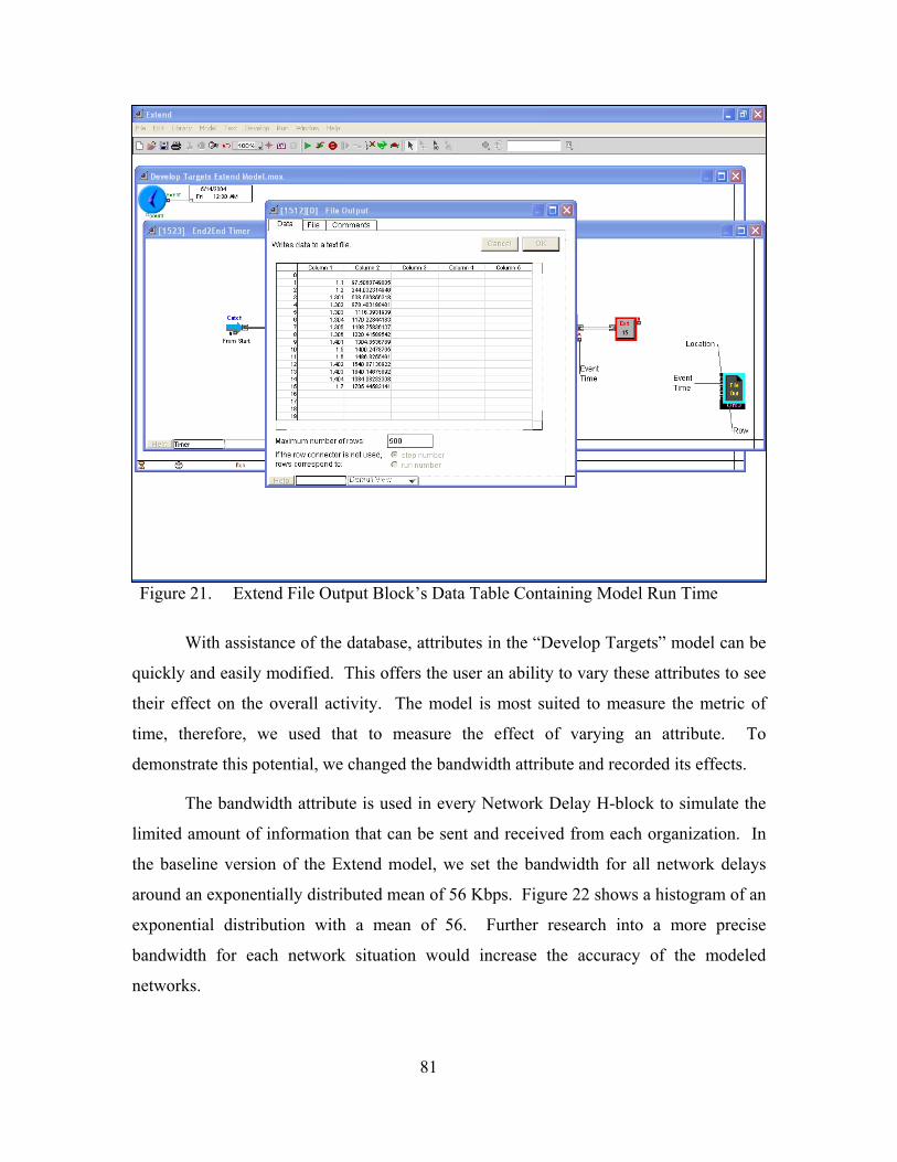
Figure 21. Extend File Output Block’s Data Table Containing Model Run Time
With assistance of the database, attributes in the “Develop Targets” model can be
quickly and easily modified. This offers the user an ability to vary these attributes to see
their effect on the overall activity. The model is most suited to measure the metric of
time, therefore, we used that to measure the effect of varying an attribute. To
demonstrate this potential, we changed the bandwidth attribute and recorded its effects.
The bandwidth attribute is used in every Network Delay H-block to simulate the
limited amount of information that can be sent and received from each organization. In
the baseline version of the Extend model, we set the bandwidth for all network delays
around an exponentially distributed mean of 56 Kbps. Figure 22 shows a histogram of an
exponential distribution with a mean of 56. Further research into a more precise
bandwidth for each network situation would increase the accuracy of the modeled
networks.
81
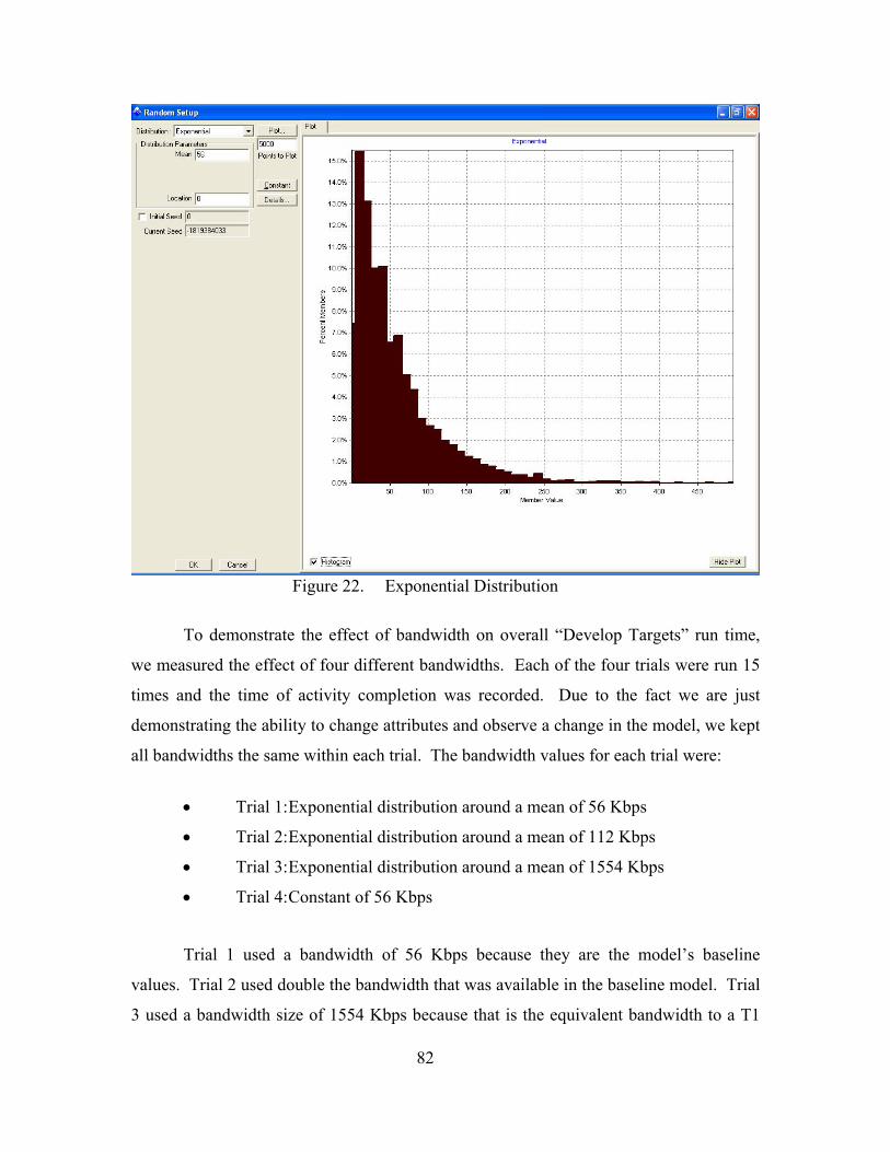
Figure 22. Exponential Distribution
To demonstrate the effect of bandwidth on overall “Develop Targets” run time,
we measured the effect of four different bandwidths. Each of the four trials were run 15
times and the time of activity completion was recorded. Due to the fact we are just
demonstrating the ability to change attributes and observe a change in the model, we kept
all bandwidths the same within each trial. The bandwidth values for each trial were:
• Trial 1: Exponential distribution around a mean of 56 Kbps
• Trial 2: Exponential distribution around a mean of 112 Kbps
• Trial 3: Exponential distribution around a mean of 1554 Kbps
• Trial 4: Constant of 56 Kbps
Trial 1 used a bandwidth of 56 Kbps because they are the model’s baseline
values. Trial 2 used double the bandwidth that was available in the baseline model. Trial
3 used a bandwidth size of 1554 Kbps because that is the equivalent bandwidth to a T1
82
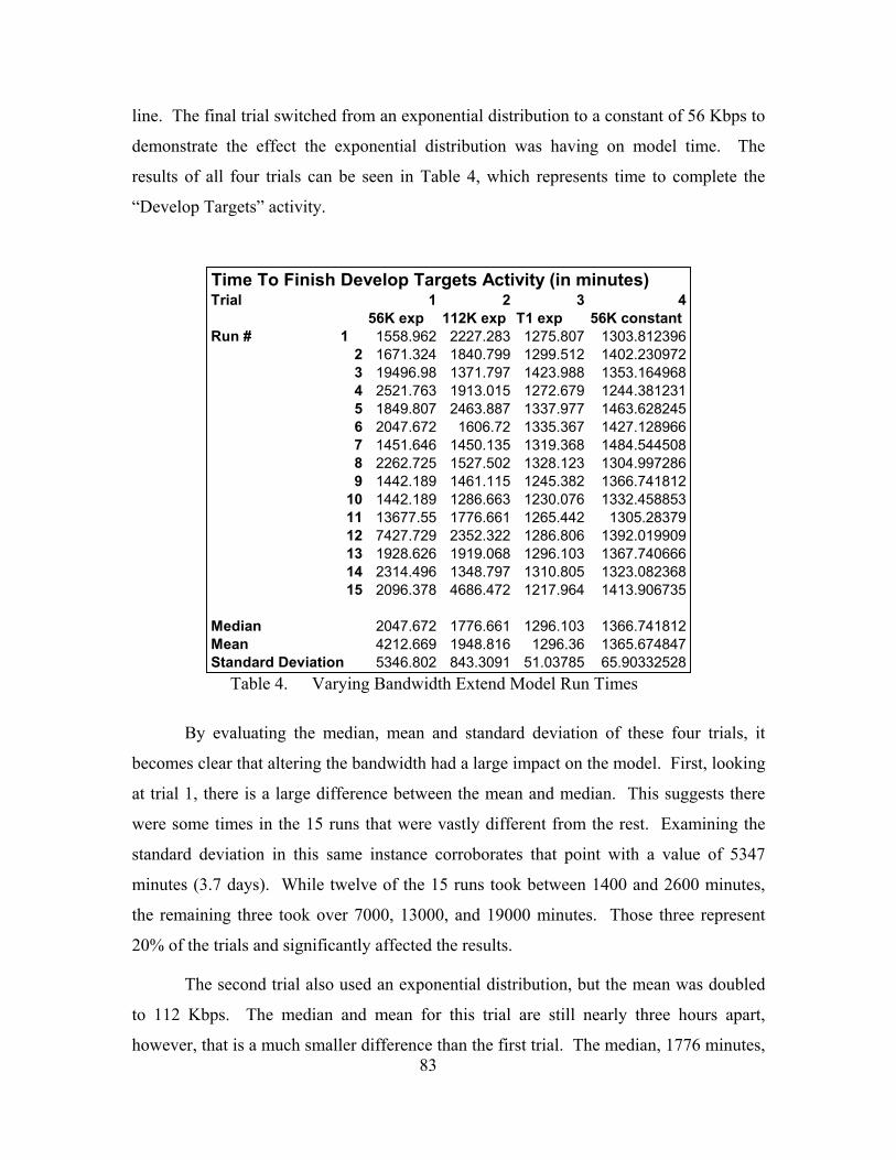
line. The final trial switched from an exponential distribution to a constant of 56 Kbps to
demonstrate the effect the exponential distribution was having on model time. The
results of all four trials can be seen in Table 4, which represents time to complete the
“Develop Targets” activity.
Table 4. Varying Bandwidth Extend Model Run Times
Time To Finish Develop Targets Activity (in minutes)Trial 1 2 3 4
56K exp 112K exp T1 exp 56K constantRun # 1 1558.962 2227.283 1275.807 1303.812396
2 1671.324 1840.799 1299.512 1402.2309723 19496.98 1371.797 1423.988 1353.1649684 2521.763 1913.015 1272.679 1244.3812315 1849.807 2463.887 1337.977 1463.6282456 2047.672 1606.72 1335.367 1427.1289667 1451.646 1450.135 1319.368 1484.5445088 2262.725 1527.502 1328.123 1304.9972869 1442.189 1461.115 1245.382 1366.741812
10 1442.189 1286.663 1230.076 1332.45885311 13677.55 1776.661 1265.442 1305.2837912 7427.729 2352.322 1286.806 1392.01990913 1928.626 1919.068 1296.103 1367.74066614 2314.496 1348.797 1310.805 1323.08236815 2096.378 4686.472 1217.964 1413.906735
Median 2047.672 1776.661 1296.103 1366.741812Mean 4212.669 1948.816 1296.36 1365.674847Standard Deviation 5346.802 843.3091 51.03785 65.90332528
By evaluating the median, mean and standard deviation of these four trials, it
becomes clear that altering the bandwidth had a large impact on the model. First, looking
at trial 1, there is a large difference between the mean and median. This suggests there
were some times in the 15 runs that were vastly different from the rest. Examining the
standard deviation in this same instance corroborates that point with a value of 5347
minutes (3.7 days). While twelve of the 15 runs took between 1400 and 2600 minutes,
the remaining three took over 7000, 13000, and 19000 minutes. Those three represent
20% of the trials and significantly affected the results.
The second trial also used an exponential distribution, but the mean was doubled
to 112 Kbps. The median and mean for this trial are still nearly three hours apart,
83 however, that is a much smaller difference than the first trial. The median, 1776 minutes,
and the mean, 1948 minutes, are slightly longer than a day. While we do not know the
exact length of the “Develop Targets” activity, we estimate it requires around a day; these
times are close to what we would expect. The standard deviation is also still very large at
843 minutes (14 hours), but again, this is much smaller than the first trial. While the
standard deviation shows there is still a large variation with each run, only one run was
particularly different from the others, at 4686 minutes.
The third trial used an exponential distribution with a mean of 1,554 Kbps. This
number
t value of 56
Kbps.
irst, it is clear that
varying
is significant because it is the bandwidth available on a T1 line. The T1 is one of
the more popular standards for digital communication in the United States (Comer 117).
The median and mean for this trial were nearly identical at 1296 minutes. Those times
are slightly less than a day, which is what the overall time for the “Develop Targets”
activity is expected to be. Also, the standard deviation was only 51 minutes, which is
what we would expect in an activity that takes about a day to accomplish.
The final trial did not use an exponential distribution, but a constan
This was a way we could see some of the potential consequences of using an
exponential distribution. The mean and median for this run were nearly identical with
values of 1366 and 1365, respectively. This length is also around the timeframe of a day
which we believe the “Develop Targets” activity will require. The standard deviation is a
manageable 65 minutes. This indicates most of the run times were similar. It is
important to remember that even though we have made the bandwidth constant, all of the
other attributes are still either exponentially or normally distributed.
These results reveal several characteristics about the model. F
an attribute, such as bandwidth, will substantially affect the “ Develop Targets”
model run time. Second, using an exponential distribution for bandwidth might not be
the best distribution. This is especially true when the mean value of the exponential
distribution is as low as 56 Kbps. As Figure 22 shows, it produces an available
bandwidth that is often too low to support the level of detail in this model. This is
discussed further in the Model Improvements section. However, as the mean value of the
exponential distribution gets larger, it appears the exponential distribution produces more
expected results. This can be seen with the slightly reduced standard deviation in trial 2,
84
and the minimal standard deviation in trial 3. It is important to note that the standard
deviation in trial 3 is even smaller than when there is no variance in the bandwidth as
shown in trial 4. With a number as large as 1544 kbps set as the mean for the exponential
distribution, the chances of a very small bandwidth are minute. Therefore, it appears that
exponential distributions can be used to demonstrate the variations that occur in
bandwidth, if the mean bandwidth is large enough.
C. MODEL IMPROVEMENTS
hat this is just a baseline model, and there is room
for sign
e Accuracy
f tracking time to complete activities within the
overall
ne key problem area with the current “Develop Targets” model has to do with
the ass
It is important to keep in mind t
ificant improvement in future iterations. This section will serve to highlight some
of the potential means of upgrading the model.
1. Increas
Currently, the model is capable o
process. However, many of the attributes that have been entered into the
database, such as link bandwidth, message size, distance, and process delay, are based
largely on assumptions. The true value of the timing function of the model will be
realized as these parameters are refined and made to be more accurate and representative
of what is actually occurring. This can be done as more time and research is spent talking
to actual operators and generating tables of statistics for each of the attributes in the
model.
O
umption that all communication link bandwidths are exponentially distributed
about a mean of 56 Kbps. It was recommended that link bandwidths best fit an
exponential distribution; however, at 56 Kbps, it is not uncommon to get several runs
where this bandwidth is as low, or less than, 1 Kbps. This means that for a message of 10
MB to be transmitted over a link operating at 1 Kbps would delay the process more than
2.5 hours. This demonstrates the need to increase the detail in the communications delay
blocks. The network delay blocks are currently configured to delay the process by over
2.5 hours when a 10 MB file is being sent over a link operating at 1 kbps. This logic may
not be entirely accurate since there is the possibility for either the link bandwidth to
85
increase or decrease over this time period, or perhaps alternate means of transmitting the
information will be sought out. If through further research it is found that either or both
of these scenarios occur, the network delay blocks can be configured to account for this.
Furthermore, activities that occur throughout this process are currently
represe
. Alternate Metrics hat is being tracked by the baseline model.
Interop
ble to implement interoperability checks in the way of
messag
the model to generate time that more accurately reflect reality.
nted by a single activity delay block, which delays the process by a set amount of
time. For example, there is currently a single, normal distribution, which represents how
long it takes each of the targeteers to develop their initial candidate target lists. While
this logic is suitable for the baseline model, there is ample room for improvement by
actually studying every task completed by each organization throughout the process.
This will ultimately lead to developing hierarchical blocks that contain several activity
delay blocks to more accurately represent the activity. Again, this comes down to how
detailed a model the user needs to produce in order to answer the questions posed of
them.
2Time is the primary metric t
erability checks is another tasking that the final model is capable of handling.
Given the labeling system of the model, there are currently ways to notice and test for
potential interoperability problems. For example, each network delay is labeled with
which system (JDISS, GCCS, AFATDS, etc) is actually being used according to the
documentation. By looking at the model it is readily apparent over what systems
information is flowing into an organization, and over what systems it is flowing out. By
understanding the compatibility of these systems, areas where interoperability problems
could exist might be highlighted.
In the future, it is conceiva
e format type checks. For example, before any item is received by a system, it
must go through a loop in which it is tested for compatibility. If it is compatible, the item
will flow through and there will be no hold-up in the process. However, if it is deemed
incompatible, the process can be set to stop and note the error, or continue with some sort
of delay associated with reformatting the item to render it compatible. This will enable
86
One final metric that could be added to this model has to do with manpower.
Each activity could be assigned a limited number of workers in the form of a resource
labor p
ock, in its current configuration, will output the time to complete each
section a tab that an average
can be
ool. The number of workers, and their tasking situation, could result in additional
delays that would be unaccounted for otherwise. The discovery of bottlenecks in the
process due to manpower could result in a re-distribution of workers present in the
organizations.
3. Enhancing the Timer Block to Process Multiple Runs
The timer bl
to le for a single run. However, if many runs are desired so
attained in a monte-carlo type scenario, each run’s time outputs will overwrite the
previous run’s times. Given the purpose of this model, monte-carlo runs will be used
quite frequently to generate results. In order to record each run’s time statistics to a
separate table, an attribute must be set at the very beginning to denote what number run
the item is associated with, and each timer throw block will get that attribute and write
that time to a column in the table that corresponds to the run number.
87

THIS PAGE INTENTIONALLY LEFT BLANK
88
LIST OF REFERENCES
ADVANCED FIELD ARTILLERY TACTICAL DATA SYSTEM (AFATDS). FY01. 24 May 2004. <http://www.globalsecurity.org/military/library/budget/fy2001/dot-e/army/01afatds.html>.
Advanced Field Artillery Tactical Data System (AFATDS). 12 Sep 1998. 24 May 2004.
<http://www.fas.org/man/dod-101/sys/land/afatds.htm>. All-DoD Core Architecture Data Model (CADM) Volume I – Overview Description.
Office of the Assistant Secretary of Defense (Networks and Information Integration). Architecture and Interoperability Directorate, Office of the Chief Information Officer (CIO). Interim Draft Report: Sep 2003.
ALL SOURCE ANALYSIS SYSTEM (ASAS). FY99. 24 May 2004.
<http://www.globalsecurity.org/military/library/budget/fy1999/dot-e/army/99asas.html>.
Comer, Douglas E. Computer Networks and Internets. 3rd Ed. Prentice Hall: New Jersey,
2001. Defense Message System. 27 Feb. 2001. 24 May 2004.
<http://searchcrm.techtarget.com/gDefinition/0%2C294236%2Csid14_gci526303%2C00.html>.
DEFENSE MESSAGE SYSTEM (DMS). 24 May 2004.
<http://www.redstone.army.mil/documents/dmswhite.html>. DISA Fact Sheets: Defense Message System (DMS). 07 May 2004. 24 May 2004.
<http://www.disa.mil/pao/fs/dms3.html>. Extend Overview. 2004. 24 May 2004.
<http://www.imaginethatinc.com/prods_overview.html>. EXTEND v6 User’s Guide. Imagine That, Inc. 2002. Ferens, Daniel., and Gerard Mangenot. Joint Targeting Toolbox Provides Vital Support
to the Warfighter. 24 May 2004. <http://www.afrlhorizons.com/Briefs/Sept02/IF0203.html>.
Global Broadcast Service. 06 July 1999. 24 May 2004.
<http://www.fas.org/spp/military/program/com/gbs.htm>.
89
GLOBAL COMMAND AND CONTROL SYSTEM (GCCS). FY98. 24 May 2004. <http://www.globalsecurity.org/military/library/budget/fy1998/dot-e/other/98gccs.html>.
Information Technology for the 21st Century. 1998. 24 May 2004.
<http://www.stl.nps.navy.mil/it21_files/frame.htm#slide0089.htm>. JIIB ACTIVITY REPORT – FEB 04. Naval Postgraduate School. Feb. 2004. Joint Intelligence Interoperability Board Systems Baseline Assessment Report. Joint
C4ISR Battle Center, January 2003. JIIB System Baseline Assessment (JSBA) FY04 Project. Naval Postgraduate School. Joint Targeting Toolbox. 25 Mar. 2004. 24 May 2004.
<http://www.rl.af.mil/tech/programs/jtt/>. Joint Vision 2020. US Government Printing Office. Washington DC: June 2000. Kimmel, Rich. Process Model Design for the Joint Intelligence Interoperability Board
(JIIB): Targeting Architecture. Naval Postgraduate School. 15 Apr. 2004. LOGISTICS AUTOMATION SYSTEMS & ENABLERS. 13 Apr. 1998. 24 May 2004.
<http://www.almc.army.mil/SLS/reserves/RCMCSS%20CSS%20Automation%20Systems%20-%20handout%20%28tlog%29.htm>.
National Defense University Library (NDU). 24 May 2004.
<http://www.ndu.edu/library/goldnich/goldnich.html>. NGA: About NGA: Fact Sheets. 24 May 2004.
<http://www.nima.mil/portal/site/nga01/>. Osmundson, John S. A Systems Engineering Methodology for Information Systems.
Systems Engineering. Vol. 3. No. 2. (2000): 68-81. Pike, John. All Source Analysis System [ASAS]. 25 Nov. 1998. 24 May 2004.
<http://www.fas.org/irp/program/process/asas.htm>. Pike, John. Image Product Library [IPL]. 08 May 2000. 24 May 2004.
<http://www.fas.org/irp/program/disseminate/ipl.htm>. Pike, John. Joint Collection Management Tools (JCMT). 08 May 2000. 24 May 2004.
<http://www.fas.org/irp/program/task/jcmt.htm>. Pike, John. Joint Deployable Intelligence Support System [JDISS]. 26 Jan. 2000. 24 May
2004. <http://www.fas.org/irp/program/process/jdiss.htm>.
90
Pike, John. Joint Maritime Command Information System (JMCIS). 28 Sep 1998. 24 May
2004. <http://www.fas.org/irp/program/core/jmcis.htm>. Pike, John. Joint Worldwide Intelligence Communications System [JWICS]. 18 Jan. 1999.
24 May 2004. <http://www.fas.org/irp/program/disseminate/jwics.htm>. Pike, John. Secret Internet Protocol Router Network (SIPRNET). 03 Mar. 2000. 24 May
2004. <http://www.fas.org/irp/program/disseminate/siprnet.htm>. Shannon, William. Joint Deployable Intelligence Support System (JDISS). FY02. 24
May2004. <http://www.globalsecurity.org/intell/library/reports/2001/compendium/jdiss.htm>.
Special Operations Forces (SOF). 14 Nov. 2003. 24 May 2004.
<http://www.ciponline.org/facts/sof.htm>. THEATER BATTLE MANAGEMENT CORE SYSTEM (TBMCS). FY99. 24 May 2004.
<http://www.globalsecurity.org/military/library/budget/fy1999/dot-e/airforce/99tbmcs.html>.
Volume I, Introduction. U.S. Central Command’s Objective Architecture Concerning
Targeting. US CENTCOM, 1997. Volume II, Objective Architecture: Operational and Systems View. U.S. Central
Command’s Objective Architecture Concerning Targeting. USCENTCOM, 1997. Volume III, References. U.S. Central Command’s Objective Architecture Concerning
Targeting. USCENTCOM. 1997.
91

THIS PAGE INTENTIONALLY LEFT BLANK
92

INITIAL DISTRIBUTION LIST
1. Defense Technical Information Center Ft. Belvoir, Virginia
2. Dudley Knox Library Naval Postgraduate School Monterey, California
3. Rich Kimmel Naval Postgraduate School Monterey, California
4. John Osmundson Naval Postgraduate School Monterey, California
5. Bill Kemple
Naval Postgraduate School Monterey, California
6. Dan Boger
Naval Postgraduate School Monterey, California
93