Embed Size (px)
Citation preview

NAVAL
POSTGRADUATE SCHOOL
MONTEREY, CALIFORNIA
THESIS
Approved for public release; distribution is unlimited
A SYSTEM OF SYSTEMS INTERFACE HAZARD ANALYSIS TECHNIQUE
by
Patrick Redmond
March 2007
Thesis Co-Advisors: J. Bret Michael Paul Shebalin

THIS PAGE INTENTIONALLY LEFT BLANK

i
REPORT DOCUMENTATION PAGE Form Approved OMB No. 0704-0188 Public reporting burden for this collection of information is estimated to average 1 hour per response, including the time for reviewing instruction, searching existing data sources, gathering and maintaining the data needed, and completing and reviewing the collection of information. Send comments regarding this burden estimate or any other aspect of this collection of information, including suggestions for reducing this burden, to Washington headquarters Services, Directorate for Information Operations and Reports, 1215 Jefferson Davis Highway, Suite 1204, Arlington, VA 22202-4302, and to the Office of Management and Budget, Paperwork Reduction Project (0704-0188) Washington DC 20503. 1. AGENCY USE ONLY (Leave blank)
2. REPORT DATE March 2007
3. REPORT TYPE AND DATES COVERED Master’s Thesis
4. TITLE AND SUBTITLE A System of Systems Interface Hazard Analysis Technique 6. AUTHOR(S) Patrick Redmond
5. FUNDING NUMBERS
7. PERFORMING ORGANIZATION NAME(S) AND ADDRESS(ES) Naval Postgraduate School Monterey, CA 93943-5000
8. PERFORMING ORGANIZATION REPORT NUMBER
9. SPONSORING /MONITORING AGENCY NAME(S) AND ADDRESS(ES) N/A
10. SPONSORING/MONITORING AGENCY REPORT NUMBER
11. SUPPLEMENTARY NOTES The views expressed in this thesis are those of the author and do not reflect the official policy or position of the Department of Defense or the U.S. Government. 12a. DISTRIBUTION / AVAILABILITY STATEMENT Approved for public release; distribution is unlimited.
12b. DISTRIBUTION CODE
13. ABSTRACT (maximum 200 words) The next generation of military capabilities will hinge on systems of systems technologies, entailing the
integration of numerous large scale systems into a complex system of systems whose capability exceeds the capabilities of the individual systems. The increase in capability is due to the emergent properties of the system of systems. However, these emergent properties also introduce hazards that must be adequately dealt with before the system of systems can be employed. The current state of hazard analysis processes is insufficient to deal with the complexity and size of a system of systems. This thesis aims to define the nature and types of hazards associated with systems of systems and to define a technique for identifying specific hazards within a system of systems.
In addition to developing a theoretical process, this thesis applies it to a real world case study, the Ballistic Missile Defense System. A software application was developed to prove the concept of the hazard analysis technique. The technique has been designed from the top down to be compatible with current system safety processes and as such, is directly compatible with systems of systems currently in development and familiar to practicing system safety engineers.
15. NUMBER OF PAGES
151
14. SUBJECT TERMS Systems of Systems, System Safety, System Hazard Analysis, Emergent Hazards
16. PRICE CODE
17. SECURITY CLASSIFICATION OF REPORT
Unclassified
18. SECURITY CLASSIFICATION OF THIS PAGE
Unclassified
19. SECURITY CLASSIFICATION OF ABSTRACT
Unclassified
20. LIMITATION OF ABSTRACT
UL NSN 7540-01-280-5500 Standard Form 298 (Rev. 2-89) Prescribed by ANSI Std. 239-18

ii
THIS PAGE INTENTIONALLY LEFT BLANK

iii
Approved for public release; distribution is unlimited
A SYSTEM OF SYSTEMS INTERFACE HAZARD ANALYSIS TECHNIQUE
Patrick J. Redmond Flight Lieutenant, Royal Australian Air Force B.Eng., University of New South Wales, 2002
Submitted in partial fulfillment of the requirements for the degrees of
MASTERS OF SCIENCE IN SOFTWARE ENGINEERING
and MASTERS OF SCIENCE IN SYSTEMS ENGINEERING
from the
NAVAL POSTGRADUATE SCHOOL
March 2007
Author: Patrick Redmond
Approved by: Prof. J. Bret Michael Co-Advisor
Prof. Paul Shebalin Co-Advisor
Prof. Peter Denning Chairman, Department of Computer Science Prof. Wayne Hughes Chairman, System Engineering and Analysis Curriculum Committee

iv
THIS PAGE INTENTIONALLY LEFT BLANK

v
ABSTRACT
The next generation of military capabilities will hinge on systems of
systems technologies, entailing the integration of numerous large-scale systems
into a complex system of systems whose capability exceeds the capabilities of
the individual systems. The increase in capability is due to the emergent
properties of the system of systems. However, these emergent properties also
introduce hazards that must be adequately dealt with before the system of
systems can be employed. The current state of hazard analysis processes is
insufficient to deal with the complexity and size of a system of systems. This
thesis aims to define the nature and types of hazards associated with systems of
systems and to define a technique for identifying specific hazards within a system
of systems.
In addition to developing a theoretical process, this thesis applies hazard
analysis to a real-world case study, the Ballistic Missile Defense System. A
software application was developed to prove the concept of the hazard analysis
technique. The technique has been designed from the top down to be compatible
with current system safety processes and as such, is directly compatible with
systems of systems currently in development and familiar to practicing system
safety engineers.

vi
THIS PAGE INTENTIONALLY LEFT BLANK

vii
TABLE OF CONTENTS
I. INTRODUCTION............................................................................................. 1 A. OVERVIEW .......................................................................................... 1 B. OBJECTIVES....................................................................................... 2
II. BACKGROUND.............................................................................................. 3 A. INTRODUCTION.................................................................................. 3 B. SYSTEMS ............................................................................................ 3
1. Overview................................................................................... 3 2. Characteristics of a System.................................................... 4
a. Purpose.......................................................................... 4 b. Integrated Components................................................ 4 c. Life Cycle ....................................................................... 5
C. SYSTEMS OF SYSTEMS .................................................................... 5 1. Overview................................................................................... 5 2. Characteristics of a System of Systems................................ 6
a. Complexity..................................................................... 6 b. Emergent Behavior ....................................................... 6 c. Autonomy ...................................................................... 7
D. HAZARDS............................................................................................ 7 1. Overview................................................................................... 7 2. Terminology ............................................................................. 7
a. Failure ............................................................................ 7 b. Fault ............................................................................... 7 c. Mishap............................................................................ 8 d. Hazard ............................................................................ 8 e. Hazard Causal Factor ................................................... 9 f. Mishap Risk ................................................................... 9 g. Residual Mishap Risk ................................................. 10
E. SYSTEM SAFETY.............................................................................. 10 1. Overview................................................................................. 10 2. Safety...................................................................................... 11 3. How Safe is Safe Enough?.................................................... 11 4. System Safety Objectives ..................................................... 11 5. A System Safety Process...................................................... 12
a. Overview...................................................................... 12 b. Documentation of the System Safety Approach ...... 12 c. Identification of Hazards ............................................ 13 d. Assessment of Mishap Risk....................................... 13 e. Identification of Mishap Risk Mitigation Measures .. 13 f. Reduction of Mishap Risk to an Acceptable Level... 14 g. Verification of Mishap Risk Reduction...................... 14 h. Review of Hazards and Acceptance of Residual
Mishap Risk ................................................................. 14

viii
i. Tracking of Hazards and Residual Mishap Risk....... 14 F. SYSTEM HAZARD ANALYSES ........................................................ 14
1. Overview................................................................................. 14 2. System Hazard Analysis Objectives .................................... 15 3. System Hazard Analysis Techniques .................................. 16
a. Fault Tree Analysis ..................................................... 16 b. Event Tree Analysis .................................................... 19 c. Hazards and Operability Analysis ............................. 20
G. SYSTEMS OF SYSTEMS HAZARD ANALYSIS AND THE SYSTEM SAFETY PROCESS ........................................................... 23 1. Overview................................................................................. 23 2. Documentation of the System Safety Approach................. 23 3. Identification of Hazards ....................................................... 23 4. Assessment of Mishap Risk ................................................. 24 5. Identification of Mishap Risk Mitigation Measures............. 24 6. Reduction of Mishap Risk to an Acceptable Level ............. 24 7. Verification of Mishap Risk Reduction ................................ 25 8. Review of Hazards and Acceptance of Residual Mishap
Risk ......................................................................................... 25 9. Tracking of Hazards and Residual Mishap Risk ................. 25 10. Conclusion ............................................................................. 25
H. THE PROBLEM ................................................................................. 26 I. CONCLUSION ................................................................................... 26
III. SYSTEMS OF SYSTEMS HAZARDS .......................................................... 29 A. INTRODUCTION................................................................................ 29 B. SYSTEMS OF SYSTEMS HAZARD SPACE..................................... 29 C. TYPES OF SYSTEMS OF SYSTEMS HAZARDS ............................. 32
1. Overview................................................................................. 32 2. Single System Hazards ......................................................... 33 3. Integration Hazards ............................................................... 33
a. Overview...................................................................... 33 b. Interface Hazards ........................................................ 33 c. Proximity Hazards....................................................... 36 d. Resource Hazards....................................................... 37
4. Reconfiguration Hazards ...................................................... 39 5. Interoperability Hazards........................................................ 42
D. CONCLUSION ................................................................................... 43
IV. INTERFACE HAZARD ANALYSIS .............................................................. 45 A. INTRODUCTION................................................................................ 45 B. SCOPE............................................................................................... 45 C. INTERFACE HAZARD ANALYSIS TECHNIQUE OVERVIEW ......... 45 D. SYSTEMS OF SYSTEMS ARCHITECTURE ..................................... 46 E. SYSTEM MODELS ............................................................................ 49
1. Overview................................................................................. 49 2. Guide Words and Network Terminology.............................. 50

ix
3. Mishap Identification ............................................................. 51 4. Input Analysis ........................................................................ 51 5. Output Analysis ..................................................................... 54
F. NETWORK ANALYSIS...................................................................... 55 G. ASSESSMENT OF MISHAP RISK .................................................... 58
1. Overview................................................................................. 58 2. Consequence ......................................................................... 58 3. Probability .............................................................................. 58
H. RESIDUAL MISHAP RISK................................................................. 60 I. SYSTEMS OF SYSTEMS EVOLUTION ............................................ 63 J. CONCLUSION ................................................................................... 64
V. APPLICATION OF TECHNIQUE TO CASE STUDY.................................... 67 A. INTRODUCTION................................................................................ 67 B. SOFTWARE DEVELOPMENT........................................................... 67
1. Overview................................................................................. 67 2. Functional Requirements...................................................... 68 3. Design..................................................................................... 68
C. SYSTEM OF SYSTEMS HAZARD ANALYSIS ................................. 73 1. Overview................................................................................. 73 2. System of Systems Architecture.......................................... 74 3. System Models....................................................................... 75 4. Preliminary Hazard List ......................................................... 79 5. System of Systems Evolution............................................... 81
D. LESSONS LEARNT........................................................................... 82 E. CONCLUSION ................................................................................... 83
VI. CONCLUSION.............................................................................................. 85 A. KEY FINDINGS AND ACCOMPLISHMENTS.................................... 85 B. FUTURE WORK................................................................................. 87
APPENDIX A. INTERFACE HAZARD ANALYSIS TECHNIQUE .......................... 89
APPENDIX B. QUALITATIVE PROBABILITY COMBINATIONS.......................... 93
APPENDIX C. BALLISTIC MISSILE DEFENSE SYSTEM OVERVIEW .............. 101 A. OVERVIEW ...................................................................................... 101 B. PURPOSE........................................................................................ 101 C. SYSTEM OF SYSTEMS ARCHITECTURE ..................................... 103 D. COMPONENT SYSTEMS ................................................................ 104
1. Command and Control, Battle Management and Communications.................................................................. 104
2. Aegis Ballistic Missile Defense .......................................... 105 3. Airborne Laser ..................................................................... 106 4. Forward-Based X-Band Radar ............................................ 107 5. Ballistic Missile Defense System Space Systems ............ 108 6. Ground-based Midcourse Defense .................................... 108 7. Terminal High Altitude Area Defense................................. 109
x
8. Multiple Kill Vehicles ........................................................... 109 9. Patriot Advanced Capability-3 ............................................ 110 10. Kinetic Energy Interceptors ................................................ 110
E. SYSTEM EVOLUTION..................................................................... 110
APPENDIX D. BALLISTIC MISSILE DEFENSE SYSTEM CASE STUDY DATA 113
LIST OF REFERENCES........................................................................................ 131
INITIAL DISTRIBUTION LIST ............................................................................... 133

xi
LIST OF FIGURES
Figure 1. MIL-STD-882D System Safety Process ............................................. 12 Figure 2. Fault Tree Analysis Process............................................................... 17 Figure 3. Fault Tree Analysis Example.............................................................. 19 Figure 4. Event Tree Analysis Example............................................................. 20 Figure 5. Systems of Systems Hazard Space ................................................... 31 Figure 6. Systems of Systems Hazard Taxonomy............................................. 33 Figure 7. Interface Hazard Examples ................................................................ 34 Figure 8. Interface Hazard Model of the Blackhawk Friendly Fire Incident........ 35 Figure 9. Proximity Hazard Example ................................................................. 37 Figure 10. Resource Hazard Examples............................................................... 38 Figure 11. Reconfiguration Hazard Example....................................................... 41 Figure 12. Interoperability Hazard Example ........................................................ 43 Figure 13. Interface Hazard Analysis Technique Overview ................................. 46 Figure 14. Example System of Systems Network................................................ 47 Figure 15: Example System of Systems Architecture Diagram ........................... 48 Figure 16. System Input/Output (I/O) Model ........................................................ 50 Figure 17. System Input/Output/Mishap (IOM) Model ......................................... 50 Figure 18. Input to Mishap Link ........................................................................... 52 Figure 19. Multiple Inputs to Mishap Link ............................................................ 52 Figure 20. Input to Output Link ............................................................................ 53 Figure 21. Multiple Inputs to Single Output Link .................................................. 53 Figure 22. Single Input to Multiple Outputs Link .................................................. 53 Figure 23. Failure to Output Link ......................................................................... 54 Figure 24. Failure to Multiple Outputs Link .......................................................... 54 Figure 25. Example Interface Hazard Assembled from System Models.............. 55 Figure 26. Example Network Analysis ................................................................. 57 Figure 27. Example Network Analysis Showing Options at Each Stage.............. 57 Figure 28. Worst Case Probability Chain for Fifth Order Interface Hazards ........ 62 Figure 29. Class Diagram for Interface Hazard Analysis Concept
Demonstrator...................................................................................... 69 Figure 30. Interface Hazard Analysis Application Screen Shot – GUI ................. 71 Figure 31. Interface Hazard Analysis Application Screen Shot – Hazard
Display................................................................................................ 73 Figure 32. The Interface Hazard Analysis Technique.......................................... 89 Figure 33. Ballistic Missile Defense System Layered Defense Structure .......... 102 Figure 34. Ballistic Missile Defense System Architecture .................................. 103 Figure 35. Command and Control, Battle Management and Communications
Control Center .................................................................................. 105 Figure 36. Aegis Ballistic Missile Defense ......................................................... 106 Figure 37. Airborne Laser.................................................................................. 107 Figure 38. Forward-Based X-Band Radar ......................................................... 108 Figure 39. Terminal High Altitude Area Defense ............................................... 109

xii
THIS PAGE INTENTIONALLY LEFT BLANK

xiii
LIST OF TABLES
Table 1. Example System Hazard Analysis Report .......................................... 16 Table 2. HAZOP Process ................................................................................. 21 Table 3. HAZOP Guide Words for Software or System Interface Analysis....... 22 Table 4. Example System of Systems Architecture Table................................ 49 Table 5. Network Analysis Symbology ............................................................. 56 Table 6. Example Qualitative Probability Combinations ................................... 59 Table 7. Example Event Probabilities for the Interface Hazard from Figure
26. ...................................................................................................... 60 Table 8. Ballistic Missile Defense System Component Systems...................... 74 Table 9. Ballistic Missile Defense System Architecture Table .......................... 75 Table 10. Ballistic Missile Defense System Transmission Paths........................ 75 Table 11. Ballistic Missile Defense System Message Types.............................. 76 Table 12. Ballistic Missile Defense System Message Names ............................ 76 Table 13. Guide Words for Input and Output Analysis ....................................... 77 Table 14. Mishap List for the Aegis Destroyer.................................................... 78 Table 15. Selected Interface Hazards from the Ballistic Missile Defense
System Case Study ............................................................................ 80 Table 16. Example Hazard following the addition of the Advanced Technology
System ............................................................................................... 82 Table 17. MIL-STD-882D Mishap Probability Levels.......................................... 94 Table 18. Qualitative Probability Combinations - Limits ..................................... 97 Table 19. Qualitative Probability Levels – Middle Values ................................... 97 Table 20. Qualitative Probability Combinations – Middle Values........................ 97 Table 21. Qualitative Probability Combinations – Lower Limit – Average Risk
1.52 .................................................................................................... 98 Table 22. Qualitative Probability Combinations – Middle Values, Optimistic
Interpretation – Average Risk 1.60 ..................................................... 98 Table 23. Qualitative Probability Combinations – Middle Values, Conservative
Interpretation – Average Risk 1.92 ..................................................... 99 Table 24. Qualitative Probability Combinations – Upper Limit – Average Risk
2.00 .................................................................................................... 99 Table 25. Ballistic Missile Defense System Component System Mishaps ....... 115 Table 26. Ballistic Missile Defense System Component System Inputs ........... 118 Table 27. Ballistic Missile Defense System Component Systems Outputs ...... 120 Table 28. Aegis Destroyer Links from Input to Mishap ..................................... 121 Table 29. Aegis Destroyer Failed Outputs........................................................ 122 Table 30. Airborne Laser Links from Input to Mishap ....................................... 122 Table 31. Airborne Laser Failed Outputs.......................................................... 123 Table 32. Command and Control Center Links from Inputs to Outputs ............ 124 Table 33. Forward-based X-Band Radar Links from Input to Mishap............... 124 Table 34. Forward-based X-Band Radar Failed Outputs ................................. 125 Table 35. Ground-based Midcourse Interceptors Links from Input to Mishap .. 126

xiv
Table 36. Kinetic Energy Interceptors Links from Input to Mishap.................... 126 Table 37. Multiple Kill Vehicles Links from Input to Mishap.............................. 127 Table 38. Patriot Advanced Capability-3 Links from Input to Mishap ............... 127 Table 39. Sea-based X-Band Radar Links from Input to Mishap...................... 127 Table 40. Sea-based X-Band Radar Failed Outputs ........................................ 128 Table 41. Space-based Sensors Failed Outputs .............................................. 128 Table 42. Terminal High Altitude Area Defense Links from Input to Mishap .... 129

xv
ACKNOWLEDGMENTS
I’d like to thank the Royal Australian Air Force for providing me the
opportunity to pursue full time study. These opportunities are rare and costly and
I appreciate the privilege.
I’d also like to thank my advisors, Prof. Bret Michael and Prof. Paul
Shebalin. Their guidance has been invaluable. I greatly appreciate their flexibility
in reviewing this work so close to the deadline. Without their guidance and
contributions, this thesis would not have been possible.
Finally, I’d like to thank Miss Cheryl Emmons for supporting me through
the long nights of research, drafting and coding and for taking care of the things
this work caused me to neglect. Thank you for your understanding, patience and
support.

xvi
THIS PAGE INTENTIONALLY LEFT BLANK
1
I. INTRODUCTION
A. OVERVIEW There are currently several large, high-profile Department of Defense
acquisition programs that are seeking to develop systems of systems to address
mission needs that might otherwise prove impossible to support. A system of
systems is an integrated set of systems that uses each system in a coordinated
fashion to achieve a mission that the individual systems cannot achieve on their
own. The Ballistic Missile Defense System (BMDS) and the U.S. Army’s Future
Combat System (FCS) are example of systems of systems. These systems of
systems are extremely large, complex and hazardous. They employ
interdependencies that further complicate systems operation. A responsible
employment of a system of systems requires a system safety program that
ensures that the risk of employment is tolerable.
However, system hazard analysis techniques are unable to cope with the
size or complexity of systems of systems. In addition to being a collection of large
scale systems, a system of systems is also able to dynamically reconfigure,
which results in virtually endless system of systems states and configurations.
New hazard analysis techniques are required to deal with systems of systems.
These techniques must be capable of handling the large scale of a system of
systems and produce meaningful results while remaining economically practical.
In Chapter II, the background to the issue is provided, including the
characteristics of systems of systems that render most hazard analysis technique
ineffective and the requirements that any new hazard analysis technique must
meet. It is here that the problem to be resolved is fully defined.
Chapter III identifies and defines the types of systems of systems hazards.
It breaks the full set of hazards down into subcategories that can be more
manageably addressed. The large scale of systems of systems, and the
potentially large number of hazards means that the analysis must be subdivided
2
into manageable pieces. This chapter provides the means for doing so by
subdividing the full set of hazards into coherent hazard types that can be
addressed individually.
In Chapter IV, a hazard analysis technique is defined to address a specific
type of system of systems hazard. This technique will meet the requirements
outlined in Chapter II. Namely, it must be effective, practical and compatible with
other hazard analysis techniques.
The hazard analysis technique defined in Chapter IV will be applied to the
Ballistic Missile Defense System in Chapter V as a case study. The purpose of
this case study is to validate the effectiveness of the hazard analysis technique.
B. OBJECTIVES The objectives of this thesis are to:
(i) identify and define the nature of systems of systems hazards, (ii) define a technique that can be used to identify and analyze a
specific type of system of systems hazard, and (iii) apply this technique to a case study to demonstrate the concept.

3
II. BACKGROUND
A. INTRODUCTION Perhaps the highest profile, most controversial and most expensive
Defense program is the Ballistic Missile Defense System, which uses a large
number of current and developmental systems in a network centric environment
in order to destroy ballistic missiles in flight. The BMDS is a system of systems,
as is the U.S. Army’s FCS. These systems of systems are both highly complex
and hazardous.
A system of systems is built on systems technology. A system is in itself a
complex entity. The Ballistic Missile Defense System utilizes the Aegis system,
which is one of the most complex weapon systems ever acquired by the United
States Navy. Integration of such a system into a complex network of systems
only adds to the overall complexity of the BMDS.
In addition to being highly complex, a system of systems can also be
hazardous. In fact, all of the mishaps that are possible within the systems are
also possible within the system of systems, but there are many new causes. In
order to ensure that the deployed system of systems is safe to operate, a
technique must be developed to identify the new hazards.
This chapter provides the background information necessary for the
research that follows. It will describe the basics of systems and systems of
systems technology, as well as the issues associated with system safety. The
system of systems hazard analysis problem will be described, and the questions
to be answered defined.
B. SYSTEMS 1. Overview The concept of a system is relatively new. Systems have only been
purpose-built since the middle of the twentieth century. However, there are some
examples of systems from the early twentieth century though they were not
thought of as systems at the time of their creation. As knowledge of science and

4
engineering rapidly expanded in the post-war period, engineers sought to take
advantage of the old adage “the whole is greater than the sum of the parts”. That
is, to integrate several disciplines and technologies in order to achieve a goal that
could not be achieved without cooperation. What they sought to develop was a
system, “a construct or collection of different elements that together produce
results not obtainable by the elements alone.”1
Systems have characteristics that set them apart from components, units
and other products of engineering processes. The IEEE defines a system as:
[a] set or arrangement of elements [people, products (hardware and software) and processes (facilities, equipment, material and procedures)] that are related and whose behavior satisfies operational needs and provides for the life cycle sustainment of the products.2
From this, it is clear that the characteristics of a system include, but are
not limited to, a purpose, integrated components and a life cycle.
2. Characteristics of a System a. Purpose Man-made systems are constructed to fulfill a specific purpose.
Systems are expensive and time consuming to develop and should only be
developed with a specific purpose in mind. In fact, the systems engineering
process requires that a purpose or role either be known or obtainable.3
b. Integrated Components A system is not merely a product that fulfills a purpose. A system
utilizes multiple disciplines and technologies to achieve its purpose. Subsystems
and components are used to harness each of these disciplines. The first products
to be engineered as systems were the early generation intercontinental ballistic
missiles (ICBM). The ICBM utilizes liquid or solid fuel rockets, an aerodynamic
1 A Consensus of the INCOSE Fellows Retrieved February 27, 2007 from
http://www.incose.org/practice/fellowsconsensus.aspx. 2 IEEE 1220-2005 Standard for Application and Management of the Systems Engineering
Process (2005) §3.1.34. 3 Ibid., §5.1.1.
5
case with control surfaces, electronic guidance equipment and the warhead. Not
only are each of these subcomponents highly integrated, they are also highly
complex in their own right.
c. Life Cycle A system exists for a life cycle. That is, it is conceived, developed,
produced, used and disposed. Not only does this require a system be designed
to survive for a long life cycle (e.g. greater than fifty years for the B-52), but
support systems have to be developed. A system is more than the obvious. It
includes all of the support systems, procedures, documentation, data and
personnel required to support it through a full life cycle.
C. SYSTEMS OF SYSTEMS 1. Overview The natural evolution from systems development was to integrate several
systems into a system of systems. The system of systems concept has taken a
high profile in recent years due to some large-scale, high-priority Defense
programs that employ the technology, in particular, the BMDS and FCS. These
systems of systems take established systems, each with their own purpose and
with a certain level of autonomy, and attempt to integrate them in order to
achieve capabilities and both levels of performance and dependability that the
individual systems cannot achieve on their own. A system of systems is
an amalgamation of legacy systems and developing systems that provide an enhanced military capability greater than any of the individual systems within the system of systems.4
Systems of systems share some characteristics with systems, but there
are a number of characteristics which distinguish them, and which can lead to
increased effort through the integration process. Like systems, a system of
systems is integrated in order to meet a need or to fulfill a purpose and the
system of systems will exhibit behaviors not present in any of the systems alone.
However, unlike systems, a system of systems is exponentially more complex.
4 D.S. Caffal, and J.B. Michael (2005). Architectural Framework for a System-of-Systems
IEEE International Conference on Systems, Man and Cybernetics, pp. 1876-1881.

6
The difference is so significant that systems of systems development is not
merely a larger version of systems development, but rather a new problem
altogether. Also, subsystems that are integrated to form a system are unable to
perform functions individually and are most likely unable to even operate on their
own. This is not the case for a system of systems, where the systems that make
up the system of systems are all capable of operating on their own and
performing functions that may be related to the purpose of the system of
systems.
There are a large number of characteristics of a system of systems, more
than will be discussed here. The characteristics that are discussed here are
those that have a direct influence on the safety of systems of systems.
2. Characteristics of a System of Systems a. Complexity Systems are complex. It logically follows that an integrated set of
systems will be more so. Systems of systems employ complex interactions and
dependencies between complex systems and as such, the complexity of a
system of systems is exponentially greater than the complexity of a system.
Systems may enter and leave the system of systems, may perform different
roles, may be connected to one system and not another and then vice versa. The
states of a system of systems are virtually infinite. This complexity means that
new analysis techniques are required to manage the sheer size of the problem.5
b. Emergent Behavior A system of systems can perform functions that the component
systems alone cannot achieve. The difference between what the systems can
achieve individually and what the system of systems can achieve is termed
emergent behavior.6 While some emergent behaviors are the desired effect of
creating a system of systems, they can also cause problems. Some emergent
5 G. Despotou, R. Alexander, and M. Hall-May (2003). Key Concepts and Characteristics of Systems of Systems, Technical Report DARP/BG/2003/1, University of York, §3.4.
6 Ibid., §3.7.

7
behaviors are intentional, others are not. Unintended emergent behaviors can
have significant consequences and efforts must be made to ensure that the
consequences are minimized.7
c. Autonomy A system is constructed of components that are unable to operate
on their own, and even if they could, they would not fulfill a useful purpose. In
contrast, a system of systems is constructed of systems that operate on their
own on a regular basis and are able to perform functions independently that may
be unrelated to the functions of the system of systems.8
D. HAZARDS 1. Overview There is risk associated with the operation of systems and systems of
systems. The risk is associated with the hazards present in the system or system
of systems. When dealing with systems, the terminology used by engineers to
describe risk can have meanings that are contrary to the common usage of the
terms in other contexts. What follows is an overview of the most important terms.
2. Terminology a. Failure A failure is an instance of a system, unit or component not
operating as designed. Failures may be overt (that is, the effects may be known
to operators or other system components) or insidious (that is, the effects of the
failure are not detected).
b. Fault A fault is a design or manufacturing flaw that exists within a system
or component that may or may not have caused a failure. Faults may be present
within a system for extended periods of time before manifesting as a failure. For
example, a crack in a metal brace is a fault. It becomes a failure when the crack
grows to the size where the brace breaks.
7 G. Despotou, R. Alexander, and M. Hall-May (2003). Key Concepts and Characteristics of
Systems of Systems, Technical Report DARP/BG/2003/1, University of York, §3.7. 8 Ibid., §3.1.

8
c. Mishap A mishap, or accident, is an event that causes injury or death to
personnel, loss or damage to property, or damage to the environment.9 Most
systems control or produce some form of energy. A mishap is an uncontrolled
release of that energy. For example, a nuclear meltdown is an uncontrolled
release of nuclear energy and is a mishap associated with a nuclear power plant.
An aircraft crash is the uncontrolled release of the potential energy associated
with being at altitude. However, not all uncontrolled releases of energy are
mishaps. The release must cause damage. An uncontrolled release of energy
that does not cause damage is a ‘near miss’ and may have, under different
circumstances, caused damage.10 When defining a mishap, the type of energy
release and the victim (personnel, property or the environment) must be defined.
The conditions that lead to the mishap are not part of the mishap definition.
Instead, they form part of the hazard definition.
d. Hazard Hazard is a term in common usage that has a different meaning
within systems terminology. In common usage, a hazard is a potential danger.
For example, in golf, a hazard is a sand bunker or water feature that the player
wishes to avoid. Within systems terminology, a hazard is more than just the
potential danger. A full description of a hazard must also include the conditions
that can lead to the mishap. A systems definition of a hazard within the golfing
context would be that the ball is close enough to the hazard to induce the player
into choosing to hit over it and that the ball does not make it over due to a
significant head wind. A hazard is a set of conditions that may lead to a mishap,
not just the potential danger. MIL-STD-882D defines a hazard as:
9 MIL-STD-882D Standard Practice for System Safety (2000) §3.2.6. 10 N. Leveson (1995). Safeware: System Safety and Computers Boston: Addison Wesley, p.
176.

9
[a]ny real or potential condition that can cause injury, illness or death to personnel; damage to or loss of a system, equipment or property; or damage to the environment. [emphasis added]11
e. Hazard Causal Factor A hazard causal factor is an event, condition, failure, fault or any
other aspect that is a required for a hazard to occur.
f. Mishap Risk Mishap risk is a somewhat confusing term. By strict definition,
mishap risk is:
[a]n expression of the impact and possibility of a mishap in terms of potential mishap severity and probability of occurrence.12
However, it is difficult to assign a probability of occurrence to a
mishap alone. The hazards that can lead to that mishap must be known in order
to know the conditions and events that lead to the mishap. It is the conditions and
events that have a probability of occurrence. The probability of occurrence of a
mishap is a function of the probability of occurrence of the hazards that lead to
the mishap. While it is possible to generate the probability of occurrence of a
mishap from the hazards that lead to the mishap (and there are likely to be
several hazards), it is more useful to leave the probability of occurrence at the
hazard level. For example, a nuclear meltdown can occur either due to a control
rod failure, or due to a failure of the pumps that circulate the coolant. The mishap
is the nuclear meltdown, and the mishap probability is the probability that either
the control rods fail or the pumps fail. To reduce the probability of a nuclear
meltdown, you must address either the probability of control rod failure or the
probability of pump failure.
As such, in general practice, a mishap risk is calculated for a
hazard, not a mishap. The mishap risk (or hazard risk) is an expression of the
severity of the mishap caused by the hazard and the probability of occurrence of
the conditions that lead to the hazard.
11 MIL-STD-882D Standard Practice for System Safety (2000) §3.2.3. 12 Ibid., §3.2.7.

10
g. Residual Mishap Risk The residual mishap risk is the risk that exists in the fielded
system.13 Once the hazards of a system have been identified, effort is made to
ensure that each of these hazards is acceptable. The system design may be
changed, or changes made to the operating procedure in an effort to reduce the
probability or consequence of a hazard. Once all these efforts have been
employed, there is still risk left in the system. This is the residual mishap risk.
Residual mishap risk is an important concept as it is this risk that is accepted by
the system operator or developer. In general, there is a threshold for residual
mishap risk. Above a certain level, the risk of operating a system (the residual
mishap risk) may not outweigh the benefits of operating the system.
E. SYSTEM SAFETY 1. Overview Systems are inherently dangerous. Almost without exception, a system
will control some type of dangerous force, be it electrical, chemical, potential or
nuclear. Systems engineering focuses primarily on developing system
performance and function, occasionally to the detriment of safety. System safety
is a program that runs concurrently with systems engineering that aims to
increase the safety of a system while still permitting system function. Systems
safety engineering is a specialty on its own, and most defense acquisition
programs require a system safety program by regulation. It is a complex
discipline that can take substantial resources, but it has proven to increase the
safety of deployed systems.14
13 MIL-STD-882D Standard Practice for System Safety (2000) §3.2.9. 14 N. Leveson (1995). Safeware: System Safety and Computers Boston: Addison Wesley, pp.
145-150.

11
2. Safety MIL-STD-882D defines safety as:
[f]reedom from those conditions that can cause death, injury, occupational illness, damage to or loss of equipment or property, or damage to the environment.15
For the most part, developing and employing a system involves exposure
to these conditions. The only way of avoiding this is to avoid the system. For
example, irrespective of how it is designed and built, there is always a chance
that an aircraft will crash. Successful employment of a system involves not only
recognizing the exposure (intentional or otherwise) to these conditions, but also
employing active techniques to minimize the likelihood or impact of these
conditions.
3. How Safe is Safe Enough? There is risk in everything we do. Driving a motor vehicle is a particularly
dangerous activity, and yet it is done by millions everyday. BASE jumping is also
a particularly dangerous activity, but this activity is undertaken by far fewer
people. The decision is based upon an assessment of risk versus reward or
necessity. Driving a motor vehicle is an essential task, and hence the risks
involved are readily undertaken. BASE jumping is not an essential task, and
hence it is only undertaken by those who view the benefit of the thrill worth the
risks involved. When dealing with systems, it is not possible to remove all risk.
The point at which a system becomes safe enough is the point at which the
benefit of the system outweighs the risks. This will vary not only with the type of
system involved, but also on the role of the system. For example, military aircraft
operations will accept much higher levels of risk during a time of conflict than
during training exercises.
4. System Safety Objectives According to Leveson, there are two system safety objectives: either to
“make something safer,” or “to convince a government licenser that it is already
15 MIL-STD-882D Standard Practice for System Safety (2000) §3.2.10.

12
safe.”16 In many instances, there are government regulations that require the
developer or operator of a system to conclusively demonstrate that a system
meets a mandated safety level. For example, the Federal Aviation Administration
mandates failure probability objectives for aircraft that operate within the United
States. If it cannot be demonstrated that an aircraft type meets these objectives,
then the aircraft cannot be operated. Alternatively, the developer of a system
may employ system safety techniques in order to make its product safer, usually
for economic reasons. For example, a developer of electronic products may
choose to invest in a system safety program in the hope that it will reduce the
cost of lawsuits due to accidents, or a car manufacturer may seek to make their
vehicles safer in order to make them more attractive to consumers, and hence
increase sales.
5. A System Safety Process a. Overview The system safety process is a specific application of the risk
management process with the objective of increasing the safety of the system.
Although there are numerous system safety standards, the variations to the core
process are minimal. For the purpose of this research, the system safety process
defined by MIL-STD-882D Standard Practice for System Safety will be used. This
process is shown in Figure 1, and described below.
Figure 1. MIL-STD-882D System Safety Process
b. Documentation of the System Safety Approach The system safety approach must be documented and approved by
program authorities. The documentation must identify each hazard analysis and
16 N. Leveson (1995). Safeware: System Safety and Computers Boston: Addison Wesley, p.
152.

13
mishap risk assessment process to be used and must also indicate how the
system safety program integrates into the overall system program. The
documentation also defines how risks are communicated to and accepted by the
appropriate authority and the method for tracking hazards and residual mishap
risk.17
c. Identification of Hazards Hazards must be identified through a systematic hazard analysis
process. All aspects of the system must be considered, including the hardware,
the software, the environment and the system purpose, over all phases of the
system life cycle. Identification of hazards is a collaborative process that involves
all program members.18
d. Assessment of Mishap Risk Once each hazard has been identified, the probability that the
hazard will occur and the consequence of occurrence must be determined.
Probabilities may be determined qualitatively. When determining consequence,
the effect on people, property and the environment must be considered. The
probability and consequence can be combined into a mishap risk priority index.19
e. Identification of Mishap Risk Mitigation Measures Measures that reduce the mishap risk must be identified for each
hazard with an unacceptable risk level. Each of these measures should be
assessed to determine its level of effectiveness in reducing mishap risk. In
general, risks should be mitigated in accordance with the safety design order of
precedence:20
(i) Eliminate hazards through design selection, (ii) Incorporate safety devices, (iii) Provide warning devices, and (iv) Develop procedures and training.
17 MIL-STD-882D. Standard Practice for System Safety (2000) §4.1. 18 Ibid., §4.2. 19 Ibid., §4.3. 20 Ibid., §4.4.

14
f. Reduction of Mishap Risk to an Acceptable Level Once the most appropriate measures for mitigating mishap risk
have been identified, the measures must be implemented. This may involve
creating and adding safety requirements to the system specification, making
changes to the system design or developing training procedures that avoid
hazards.21
g. Verification of Mishap Risk Reduction Any mishap risk reduction that has been performed must be verified
by analysis, inspection or test in order to ensure that the desired effect has been
achieved.22
h. Review of Hazards and Acceptance of Residual Mishap Risk
At the completion of the mishap risk reduction activities, the
appropriate authority must review the system hazards and accept the residual
mishap risk. The residual mishap risk is the risk that remains once all mishap risk
mitigation strategies have been employed. If the appropriate authority is unable
to accept the residual mishap risk, further mishap risk reduction measures need
to be employed.23
i. Tracking of Hazards and Residual Mishap Risk The hazards and residual mishap risk must be tracked as the
system evolves throughout the life cycle. This includes updating probability
assessments if they prove to be erroneous, adding or removing hazards as the
system is modified and tracking closure actions to ensure they are completed.24
F. SYSTEM HAZARD ANALYSES 1. Overview The primary task within a system safety program is a hazard analysis.
Hazard analyses can be performed at different times within the system life cycle,
at different levels within the system design and for the purpose of identifying 21 MIL-STD-882D. Standard Practice for System Safety (2000) §4.5. 22 Ibid., §4.6. 23 Ibid., §4.7. 24 Ibid., §4.8.

15
different types of hazards. A system safety program should be designed for a
specific application, and is likely to include a number of different hazard analyses
and several techniques for performing each hazard analysis. The most common
hazard analysis is a system hazard analysis, which commences early in the life
cycle (as soon as sufficient data is available for the relevant hazard analysis
technique) and continues as the system evolves. A system hazard analysis deals
with hazards at the system level (as opposed to the subsystem or unit level).
There are a large number of system hazard analysis techniques, the most
common of which are described below.
2. System Hazard Analysis Objectives The purpose of a system hazard analysis is to identify and assess
system-level hazards. System-level hazards are primarily hazards associated
with the interfaces and interactions between subsystems, but may also include
potentially safety-critical human errors.25 There are a large number of techniques
for conducting a system hazard analysis. Any system hazard analysis technique
must not only be able to identify hazards in a cost-effective fashion, it must also
employ a formal approach that either provides complete coverage of the system,
or clearly identifies the aspects of the system that have not been analyzed. The
choice of a system hazard analysis technique is application specific, and will
depend upon the criticality and complexity of the system as well as the amount of
system information that is available. Several commonly used system hazard
analysis techniques are described below.
The primary output of a system hazard analysis is a system hazard
analysis report. This report is effectively a list of all system hazards, including an
assessment of the risk associated with each hazard and the recommended
strategy for mitigating each hazard. An abridged example of a system hazard
25 National Aeronautics and Space Administration. (1999). System Safety Handbook (DHB-S-001) Edwards, CA: Dryden Research Flight Center, p. 28.

16
analysis report is shown in Table 1. Any system hazard analysis technique must
be able to populate such a table. The data to be included in the table is as
follows:26
(i) System/Subsystem/Unit. List every system, subsystem and unit to be analyzed.
(ii) Component Failure Mode. For each system, subsystem and unit, list all failure modes that can result in a hazard.
(iii) Hazard Description. Describe the hazard that results from each component failure mode.
(iv) Effect of Hazard. Determine the effect of each hazard in terms of the damage that the subsequent mishap may cause to personnel, property or the environment.
(v) Risk Assessment. Determine the risk of each hazard in terms of severity and probability before any hazard mitigation activities have been conducted.
(vi) Recommended Action. Identify the actions that must be taken in order to reduce the hazard risk to an acceptable level.
(vii) Effect of Recommended Action. Determine the risk of each hazard once all hazard mitigation activities have been conducted.
(i)
System/ Subsystem/
Unit
(ii)
Component Failure Mode
(iii)
Hazard Description
(iv)
Effect of
Hazard
(v)
Risk Assessment
(vi)
Recommended Action
(vii)
Effect of Recommended
Action
Control Rods Actuator Fails
Control rod state becomes uncontrollable, reactor overheats.
Large scale loss of life
Catastrophic
Remote
Implement fail safe design, control rods close on failure.
Marginal
Remote
… … … … … … …
Table 1. Example System Hazard Analysis Report
3. System Hazard Analysis Techniques a. Fault Tree Analysis Fault Tree Analysis (FTA) is a top-down approach to identifying the
causes of system hazards. The process requires knowledge of substantial
26 Office of Management and Budget. (1995). System Safety Hazard Analysis Report (DI-SAFT-80101B) Washington, DC.

17
system detail, and cannot be performed completely early in the process
(although it can be commenced and still prove fruitful), but does provide full
system coverage, permits quantitative analysis and combinations of failures, and
is very cost effective in identifying system hazards. An overview of the process is
shown in Figure 2.
Figure 2. Fault Tree Analysis Process27
The steps are as follows:
(i) Identify FTA Objective. Establish the purpose of the analysis and the types of mishaps to be analyzed. The objective may be to determine the probability of a mishap occurring, or to determine the most effective method of reducing a mishaps probability.
(ii) Define Fault Tree (FT) Top Event. Identify the system mishap to be analyzed within a specific fault tree. The fault tree will identify the causes and probability of the chosen mishap.
(iii) Define FTA Scope. Determine which systems will be included as contributors to the system mishap, and which will be excluded, as well as the version of the system to be analyzed and the system boundary conditions such as initial states and input ranges.
(iv) Define FTA Resolution. Determine the level to which the failure causes for the top event will be developed. The objective of the FTA may be achieved by developing the FT to the subsystem level, or it may require that the unit level be considered.
27 From National Aeronautics and Space Administration. (2002). Fault Tree Handbook with
Aerospace Applications (Version 1.1) Washington, DC: NASA Office of Safety and Mission Assurance, p. 22.
18
(v) Define FTA Ground Rules. Establish a consistent method for naming FT events and gates.
(vi) Construct FT. Starting with the top event, define the combination of lower level failures or events that will cause the top event to occur. If the top event is a system level mishap, the first level of failures will be at the subsystem level, the second level at the unit level and so on. Continue to decompose lower level events until the FTA objective can be achieved.
(vii) Evaluate FT. Evaluate the FT qualitatively and quantitatively. A qualitative analysis will determine subsets of events that can cause the top event (not every event within a FT is required to cause the top event) and will identify events whose elimination will prevent the top event. A quantitative analysis can determine the overall probability of the top event and the probability of each of the subsets that cause the top event.
(viii) Interpret/Present Results. Assess the importance of the FTA results and report them to the relevant decision maker. An example fault tree is shown in Figure 3. The top event is the
‘System Mishap’. The fault tree shows that the system mishap can be caused by
either a combination of failures F1 and F2, or by a combination of failures F3 and
F4. In order to prevent the system mishap, one of failures F1 or F2 and one of
failures F3 or F4 must be prevented. Preventing failure F1 alone does not prevent
the system mishap. Depending upon the objective of the FTA, the FT may be
further broken down. For example, failure F4 may actually be the combination of
several failures within the subsystem that exhibits failure F4.
Fault tree analysis is one of the most efficient system hazard
analysis techniques. The process begins with a system mishap, and then
expands upon the causes of that system mishap. Every step of the FTA is
therefore guaranteed to provide further insight into a system mishap. This is not
true of other system hazard analysis processes that do not employ the top down
approach. With a bottom up approach, significant effort may be expended
analyzing a subsystem failure that does not result in a system mishap.

19
Figure 3. Fault Tree Analysis Example
b. Event Tree Analysis Event tree analysis is a bottom-up hazard analysis technique that
seeks to determine the consequences of a given subsystem or unit failure. It can
be visualized as the reverse of a Fault Tree Analysis. The process that is shown
in Figure 2 can also be applied to an Event Tree Analysis. However, rather than
starting with a top event, Event Tree Analysis starts with a component failure or
partial performance. Figure 4 shows an example Event Tree Analysis. The
purpose of this tree is to determine the outcome of a ‘Component 1 Failure.’
Other events in the tree are the components that either depend upon Component
1, or are able to catch the Component 1 Failure and prevent a more serious
mishap.

20
Figure 4. Event Tree Analysis Example
Event Tree Analysis should only be used for specific purposes,
when the outcome of a component’s failure is essential to know, or if the
probability of failure of a particular component is high. Event Tree Analysis
should not be used to cover the entire system, as it has some significant flaws.
Firstly, it cannot deal with unrelated initiating failures that may compound further
along the failure chain. Secondly, a significant amount of effort can be expended
on Event Tree Analyses that provide no fruitful results. A long and complicated
Event Tree Analysis may actually result in no hazards being identified. Event
Tree Analyses should be used to supplement other hazard analysis techniques.28
c. Hazards and Operability Analysis Hazards and Operability (HAZOP) Analysis applies a systematic
exploration of system parameters and the manner in which they can fail. For
each system parameter, a list of guide words is applied in order to determine how
the system may fail and what the effects of that failure are. The HAZOP process
is summarized in Table 2, but the backbone of the process is:
Guide Word + Parameter = Deviation29
For example, when dealing with a coolant system, the parameter
may be “Flow” and the guide word could be “None,” which results in the
deviation, “No Flow”. Other guide words could be more, reverse, less, etc.
28 C. Ericson (2005). Hazard Analysis Techniques for System Safety Hoboken, NJ:
Wiley-Interscience, p. 233. 29 Ibid., p. 369.

21
Step Task Description
1 Define System
Define, scope and bound the system. Define the mission, mission phases and mission environments. Understand the system design and operation. Note that all steps are applicable for a software HAZOP.
2 Plan HAZOP
Establish HAZOP analysis goals, definitions, worksheets, schedule and process. Divide the system under analysis into the smallest segments desired for the analysis. Identify items to be analyzed and establish indenture levels for items/functions to be analyzed.
3 Select Team
Select team leader and all team members to participate in HAZOP analysis and establish responsibilities. Utilize team member expertise from several different disciplines (e.g. design, test, manufacturing, etc.).
4 Acquire Data
Acquire all of the necessary design and process data needed (e.g., functional diagrams, code, schematics and drawings) for the system, subsystems and functions. Refine the system information and design representation for HAZOP analysis.
5 Conduct HAZOP
a. Identify and list the items to be evaluated.
b. Establish and define the appropriate parameter list.
c. Establish and define the appropriate guideword list.
d. Establish the HAZOP analysis worksheet.
e. Conduct the HAZOP analysis meetings.
f. Record the HAZOP analysis results on the HAZOP worksheets.
g. Have the HAZOP analysis worksheets validated by a system engineer for correctness.
6 Recommend Corrective Action
Recommend corrective action for hazards with unacceptable risk. Assign responsibility and schedule for implementing corrective action.
7 Monitor Corrective Action
Review the HAZOP at scheduled intervals to ensure that corrective action is being implemented.
8 Track Hazards Transfer identified hazards into the hazard tracking system.
9 Document Hazop Document the entire HAZOP process on the worksheets. Update for new information and closure of assigned corrective actions.
Table 2. HAZOP Process30
30 From C. Ericson (2005). Hazard Analysis Techniques for System Safety Hoboken, NJ: Wiley-Interscience, p. 369.

22
The choice of guide words is dependent upon the system to be
analyzed. For most applications, there are lists of guide words that have
historically proven to be effective in identifying hazards. An example list of guide
words for software and system interfaces is shown in Table 3.
Guide Word Meaning
None Intended result not achieved
More Too much of some parameter
Less Not enough of a parameter
As Well As Unintended activity or material
Part Of Parts of the parameter are missing
Reverse Value is opposite of intended value
Other Than Something other than intended result happens
Omission Intended output missing
Commission Unintended output
Early Output occurs too soon
Late Output occurs too late
Coarse Incorrect Output’s value is wrong
Subtle Incorrect Output’s value is wrong, but cannot be detected
Table 3. HAZOP Guide Words for Software or System Interface Analysis31
The HAZOP process provides a systematic approach to identifying
system hazards by ensuring that all system parameters and all failure modes are
addressed, as well as providing structure to brainstorming sessions. However, it
31 J. Reese, and N. Leveson (1997). Software Deviation Analysis Proceedings of the 19th International Conference on Software Engineering pp. 250-260.

23
does have some limitations, namely that it does not consider multiple event
failures, it can take considerable effort and time to complete, and a poor choice
of guide words can result in some hazards being overlooked.32
G. SYSTEMS OF SYSTEMS HAZARD ANALYSIS AND THE SYSTEM SAFETY PROCESS 1. Overview A system of systems hazard analysis should be conducted within the
system safety program in order to maximize compatibility with system hazard
analyses and to minimize the impact on the training, experience and knowledge
base of the system safety engineering community. Some or all of the activities
within the system safety process may not be capable of handling the size and
complexity of a system of systems. Each of the system safety process steps will
be assessed to determine whether a new process will be required for that step to
accommodate systems of systems.
2. Documentation of the System Safety Approach The documentation of the system safety approach for a system of systems
can be developed in the same manner as the documentation for a system.
Although the actual approach to be documented will differ, the list of elements to
be documented remains the same; that is, the documentation must still cover the
hazard analysis and mishap risk assessment processes, as well as the means
for communicating risk, and so on. Documentation of the system safety approach
does not require a new process in order to be applied to systems of systems.
3. Identification of Hazards Systems of systems hazards cannot be economically and systematically
identified by any established hazard identification process. This is due to the size
and complexity of systems of systems. Hazard identification processes, such as
HAZOP, require engineers to analyze each aspect of the system by hand to
determine what hazards may exist. While this could be done for a system of
systems, it is not practical as it would take a very long time. Not only are systems
32 C. Ericson (2005). Hazard Analysis Techniques for System Safety Hoboken, NJ:
Wiley-Interscience, pp. 376 – 379.

24
of systems exponentially larger and more complex than systems, they also have
a large number of configurations, each of which must be analyzed individually.
Identification of hazards requires a new process in order to be applied to systems
of systems.
In addition, it is difficult to determine the emergent behaviors of a system
of systems before the systems are integrated. As such, the hazards that are
associated with the emergent behaviors cannot be determined until the system is
integrated.
4. Assessment of Mishap Risk The assessment of mishap risk is dependent upon how the hazards are
identified. Given that systems of systems will require a new process in order to
identify hazards, it is therefore also true that systems of systems will require a
new process to assess the mishap risk. However, the basic structure of the
assessment should not change. That is, each hazard should be assigned a
qualitative probability and consequence in a manner consistent with a systems
assessment. This will allow direct comparisons between hazards identified by
any new process and hazards identified by an established process. Assessment
of mishap risk will require a new process in order to be applied to systems of
systems.
5. Identification of Mishap Risk Mitigation Measures The measures that may be used to mitigate system of systems hazard risk
are similar to those used to mitigate system hazard risk. There may, however, be
more aspects of the hazard to attack given the increased complexity of systems
of systems hazards. Identification of mishap risk mitigation measures does not
require any new processes or measures in order to be applied to systems of
systems.
6. Reduction of Mishap Risk to an Acceptable Level The mishap risk reduction measures can be implemented for systems of
systems in the same manner as for systems. The effort required to mitigate a
complex system of systems hazard may be more than that required to mitigate a

25
system hazard, but the methods to be applied are the same. That is, safety
requirements can still be added to system specifications, the design can still be
changed to reduce the hazard probability and training procedures can still be
implemented. Reduction of mishap risk to an acceptable level does not require
any new processes in order to be applied to systems of systems.
7. Verification of Mishap Risk Reduction Verification of mishap risk reduction techniques are the same for systems
of systems as they are for systems. Analysis, inspection and test are all valid
methods for verifying system of systems hazard risk reduction. Verification of
mishap risk reduction does not require any new processes in order to be applied
to systems of systems.
8. Review of Hazards and Acceptance of Residual Mishap Risk An appropriate authority must accept the residual mishap risk for a system
of systems. However, the size and complexity of a system of systems means
that, unlike a system, a hazard analysis is unlikely to be complete. It is thus
difficult to know what the residual risk is. For a system, the residual risk is clearly
defined by the identified hazards and the knowledge that the hazard assessment
is complete. For a system of systems, an estimate of the residual risk must be
made with the knowledge that the hazard assessment is likely to be incomplete.
Review of hazards and acceptance of residual mishap risk will require a new
process in order to be applied to systems of systems.
9. Tracking of Hazards and Residual Mishap Risk Tracking of hazards and residual mishap risk is significantly more difficult
for systems of systems than it is for systems. Modifications to a system within a
system of systems may have far reaching and unknown effects on the hazard
space of the system of systems, far beyond the extent of the localized
modification. In order for the hazards of a system of systems to be tracked
efficiently throughout the lifecycle, a new process is required.
10. Conclusion The hazard assessment of systems of systems should fit within the
system safety process. In order for this to occur, several new processes are

26
required to complete some of the steps within the system safety process; other
steps can be completed without any new processes. In order to complete the
system safety process for a system of systems, new processes are required for:
(i) Identification of hazards, (ii) Assessment of mishap risk, (iii) Review of hazards and acceptance of residual mishap risk, and (iv) Tracking of hazards and residual mishap risk.
H. THE PROBLEM A system of systems is typically a hazardous and extremely complex
entity that must be engineered to meet acceptable safety standards. The size
and complexity of a system of systems is such that system hazard analysis
techniques are not effective.33 New hazard analysis techniques must be
developed that are able to deal with the size and complexity of a system of
systems, that can keep pace with the evolution of a system of systems over the
life cycle and that can either cover the full scope of a system of systems or
conducts the analysis in such a way that it is clear what aspects of the system of
systems have not been assessed and what the residual mishap risk is.
I. CONCLUSION Systems of systems are complex and hazardous entities. The complexity
of a system of systems is sufficient to render system hazard analysis techniques
incapable of providing full coverage, and thus applying these techniques may
leave some hazards undetected. A new hazard analysis technique is required.
The new hazard analysis technique must fit within the system safety
program framework. For some steps of the system safety process, there are
established techniques available that can be applied to systems of systems. The
following steps need new techniques to be developed:
33 B. Michael, A. Nerode, and D. Wijesekera (2006). On the Provision of Safety Assurance via Safety Kernels for Modern Weapon Systems Proceedings of the Fifth Workshop on Software Assessment p. 103.

27
(i) Identification of hazards, (ii) Assessment of mishap risk, (iii) Review of hazards and acceptance of residual mishap risk, and (iv) Tracking of hazards and residual mishap risk. In the following chapters, a hazard analysis technique will be developed
that can identify certain types of systems of systems hazards. This technique will
then be applied to the Ballistic Missile Defense System in order to validate the
effectiveness of the technique.

28
THIS PAGE INTENTIONALLY LEFT BLANK

29
III. SYSTEMS OF SYSTEMS HAZARDS
A. INTRODUCTION In order to effectively identify, analyze and mitigate systems of systems
hazards, the type and nature of these hazards must first be defined. This chapter
will describe the nature of the systems of systems hazard space and then break
systems of systems hazards down into subtypes that can be directly addressed
with identification and analysis techniques.
B. SYSTEMS OF SYSTEMS HAZARD SPACE A system of systems introduces new hazards that are not present in the
individual systems. These hazards are varied and complex, significantly more so
than the individual system hazards. In order to determine what hazards are
present in a system of systems, it must first be determined what type of hazards
may be present.
Organization of a set of systems into a system of systems creates
emergent behavior, but does not change the physical nature of the component
systems. For a mishap to occur a system must control or create energy and that
energy must be released in an unsafe manner. Integrating a set of systems does
not introduce any new energy sources. As such, no new potential mishaps are
introduced. More specifically:
{System of Systems Mishaps} = Union of {System Mishaps}
Note that while the potential mishaps do not change, the probability that a
mishap will occur may be changed dramatically. A mishap that is bordering on
impossible within a single system may be significantly more probable when
combined into a system of systems. In addition, the emergent behaviors of the
system of systems create new means by which the mishaps can occur, that is,
they create new hazards.
{System of Systems Hazards} ≠ Union of {System Hazards}

30
These relationships are not new; they are an extension of the relationships
between a system and its integrated components. A system of systems is similar
to a system in that they both entail the integration of less complex components or
systems into a more complex system or system of systems that exhibits
emergent behaviors that the components or systems cannot perform on their
own.
As an example, consider the simplest of interactions between a forward
observer (such as an AWAC aircraft) that is providing target data to a destroyer
armed with Tomahawk surface to surface missiles. The destroyer has the
potential to launch a Tomahawk against the wrong target which, if the location
turns out to be civilian or friendly, results in a mishap. This mishap can occur
whether or not the destroyer is part of the larger system of systems. However, if
the destroyer is not part of the larger system of systems, a launch against an
incorrect target must be caused within the destroyer system. Once the destroyer
becomes part of the system of systems, there are new ways that the erroneous
launch can occur. That is, the forward observer can provide incorrect target
information to the destroyer. The creation of the system of systems (albeit
simple) has not introduced a new mishap, but it has introduced a new hazard.
The theoretical hazard space of a system of systems is shown
diagrammatically in Figure 5. Each system that is part of a system of systems
brings with it its own hazards. That is, the hazard space of System of Systems 1
is at least equal to the hazard space of individual systems A, B and C. Each of
the hazards present in these systems may still occur within a system of systems
context and are hence part of the set of system of systems hazards. However,
there are also hazards within the system of systems that cannot be allocated to a
single system. These are emergent hazards. In the above example, when a
forward observer provides incorrect target data to a destroyer, and the destroyer
launches a Tomahawk at the incorrect target, the resultant hazard cannot be
solely attributed to either the forward observer or the destroyer. It is a hazard that
belongs to the system of systems.

31
Figure 5 also demonstrates that system of systems hazards are context
dependent. One of the advantages of a system of systems is that it is
reconfigurable, both dynamically and through system replacement, removal or
addition. This allows the system of systems to adapt to changing functional
requirements or operational scenarios. For example, consider if System of
Systems 1 is reconfigured such that System A is replaced by System E and
System F is added. The hazard space is now altered to System of Systems 2.
While the core of the System of Systems (Systems B and C) remains the same,
and the function may remain ostensibly the same, the hazard space has been
altered dramatically. In addition to the new hazards introduced by the new
configuration, there may also be hazards introduced by the transition between
configurations.
Figure 5. Systems of Systems Hazard Space

32
C. TYPES OF SYSTEMS OF SYSTEMS HAZARDS 1. Overview Given that a system of systems introduces new hazards that are not
present in the component systems, it must be determined what types of hazards
are introduced. It is evidently possible for a system of systems hazard to be
extremely complex. The more that is known about the types of hazards that may
exist, the more likely it is that the hazards that do exist will be found.
Systems of systems hazards are easily separable into two distinct
categories, single system hazards and emergent hazards. A single system
hazard is a hazard that is attributable to a single system alone, an emergent
hazard is a hazard that results from the integration of several systems into a
system of systems and hence cannot be attributed to a single system. Emergent
hazards can be further subdivided into reconfiguration hazards, integration
hazards and interoperability hazards. The taxonomy of systems of systems
hazards is shown in Figure 6. These hazard types are further defined below.
Definition: A system of systems hazard is any hazard that may occur
within a system of systems.
Definition: An emergent hazard is any hazard that may occur within a
system of systems that is not attributable to a single system.

33
Figure 6. Systems of Systems Hazard Taxonomy
2. Single System Hazards A single system hazard is a hazard that is attributable to a single system
alone. These hazards are identified by the system hazard analysis process and
are outside the scope of a system of systems hazard analysis. The purpose of a
system of systems hazard analysis is to identify all systems of systems hazard
except for single system hazards.
Definition: A single system hazard is any hazard that may occur within a
system of systems that is attributable to a single system and may occur whether
or not that system is operating within the system of systems context.
3. Integration Hazards a. Overview Integration hazards are a type of emergent hazard that result from
the integration of systems into a system of systems. The vast majority of systems
of systems hazards are integration hazards, which can be further subcategorized
into three types, interface hazards, proximity hazards and resource hazards.
b. Interface Hazards Definition: An interface hazard is a hazard in which one system
causes a mishap in another system by transferring a failure or partial
performance over a defined interface, possibly through another system.
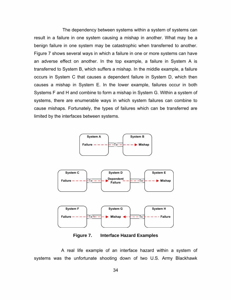
34
The dependency between systems within a system of systems can
result in a failure in one system causing a mishap in another. What may be a
benign failure in one system may be catastrophic when transferred to another.
Figure 7 shows several ways in which a failure in one or more systems can have
an adverse effect on another. In the top example, a failure in System A is
transferred to System B, which suffers a mishap. In the middle example, a failure
occurs in System C that causes a dependent failure in System D, which then
causes a mishap in System E. In the lower example, failures occur in both
Systems F and H and combine to form a mishap in System G. Within a system of
systems, there are enumerable ways in which system failures can combine to
cause mishaps. Fortunately, the types of failures which can be transferred are
limited by the interfaces between systems.
Figure 7. Interface Hazard Examples
A real life example of an interface hazard within a system of
systems was the unfortunate shooting down of two U.S. Army Blackhawk

35
helicopters over Iraq by two U.S. Air Force F-15s. The Blackhawk helicopters
were present in the No-Fly zone when the F-15s commenced their patrol. The
F-15s were unable to positively identify the helicopters, which appeared as an
unidentified contact on their radar screens. There was an Airborne Warning and
Control (AWAC) aircraft in the region that also had contact with the helicopters.
Although the AWAC aircraft correctly identified the helicopters as friendly, when
the information was passed to the F-15s the helicopters were designated as
unidentified. Based on this information, the F-15s destroyed the Blackhawk
helicopters.34
The Blackhawk friendly fire incident is an example of an interface
hazard. Although there were other contributing causes (not discussed), a
significant contributing factor was the dependence of the F-15 upon the AWAC
aircraft. The failure within the AWAC aircraft (misidentifying the radar contact)
was transferred to the F-15 via a defined interface (in this instance, radio
communications). A diagrammatic representation of this incident as an interface
hazard is shown in Figure 8.
Figure 8. Interface Hazard Model of the Blackhawk Friendly Fire Incident
34 R. Alexander, M. Hall-May, and T. Kelly (2004). Characterisation of Systems of Systems Failures. Proceedings of the 22nd Annual System Safety Conference. Unionville, VA, System Safety Society.

36
c. Proximity Hazards Definition: A proximity hazard is a hazard in one system that is
caused by the operation, failure or partial performance of another system that is
transferred to the victim system by a means other than a defined interface.
A system of systems utilizes a network of systems that is, more
often than not, geographically distributed. However, the systems of a system of
systems operate with a certain amount of autonomy. As such, it is possible that
systems may come within close physical proximity of one another. In some
systems of systems, systems may come in close proximity as a part of regular
operations. An interface hazard occurs when one system adversely affects
another system via a defined interface. When systems come within close35
proximity of each other, it is possible for one system to adversely affect another
system without using a defined interface. This is a proximity hazard.
Figure 9 demonstrates the concept of a proximity hazard. System B
radiates some form of energy. This radiation may be the result of a failure, but
may also be the result of normal operation. Systems A1 and A2 are identical
systems. System A1 suffers a mishap as it is close enough to System B to suffer
adverse effects. System A2 does not suffer a mishap as it sufficiently removed
from System B to avoid the propagated energy. The types of propagated energy
that may cause mishaps in other systems are many and varied, but likely
suspects are electromagnetic energy, heat or gas from rocket exhausts and
kinetic energy from projectile weapons. The effects of electromagnetic energy
may be overt, such as damage to another system through sheer magnitude of
energy, or subtle, such as the corruption of data signals through increased noise.
35 Note: Close is a relative term that depends upon the nature of the systems involved.
“Close” when dealing with the ignition of a rocket engine is significantly shorter than “close” when dealing with HF transmissions.

37
Figure 9. Proximity Hazard Example
A proximity hazard occurred in 1967 off the coast of Vietnam as a
U.S. Navy jet was landing on the U.S.S. Forrestal. The radar systems on the
Forrestal caused a short and the uncommanded release of a weapon from the
landing aircraft. The weapon struck a fully armed and fueled aircraft sitting on the
deck. In the resultant explosion, 134 sailors died and the carrier was severely
damaged.36 Aircraft and the weapons they carry are now designed to be less
susceptible to electromagnetic radiation. The Forrestal accident occurred
because the landing aircraft was within close proximity to the carrier and the
carrier was propagating energy that had the potential to cause adverse effects in
other systems.
d. Resource Hazards Definition: A resource hazard is a hazard that results from
insufficient shared resources or resource conflicts.
Systems within a system of systems share resources. When
systems, subsystems or components are integrated, unless it is through an
36 National Aeronautics and Space Administration. (1995). Electronic Systems Failures and Anomalies Attributed to Electromagnetic Interference (NASA-RP-1374). NASA Marshall Space Flight Center.

38
outdated point to point wiring, then it is through shared resources. If the systems
are dependent upon the resource, or dependent upon the integration that the
resource provides, then mishaps may result from a compromise of that resource.
Examples of resources that may be shared are bandwidth, airspace, network
addresses or memory. There are two types of resource hazards, insufficient
resources or resource conflicts. These types of resource hazards are shown in
Figure 10. On the left is an example of insufficient resources. Both System A and
System B have a requirement for a certain amounts of Resource A. The sum of
the systems’ resource requirements is greater than the amount of resource
available. If either System A or System B is dependent upon access to the
resource, then the performance of that system may be degraded or hazardous.
On the right is an example of a resource conflict. System C and System D have a
requirement for a certain part of Resource B. In this instance, Resource B exists
in sufficient amounts to cover the magnitude of the systems’ resource
requirements. However, System C and System D have requested access to the
same section of Resource B. Again, if either system is dependent upon access to
Resource B, a hazardous situation may occur.
Figure 10. Resource Hazard Examples
Within the system of systems context, the most likely resource
hazard to result from insufficient resources is a hazard that results from

39
insufficient bandwidth. The distributed nature of a system of systems means that
communications must travel through the atmosphere, which places a limit on the
bandwidth available (as opposed to cable based communications, where
bandwidth can be increased by adding cables, atmospheric bandwidth is fixed).
An example of this type of hazard may occur when a large number of Unmanned
Aerial Vehicles (UAVs) are operating in the same area. If the bandwidth is
insufficient to support the number of UAVs, one or more of the UAVs may lose
communications and become uncontrollable, resulting in a potentially hazardous
situation.
Resource conflicts are particularly applicable to the Air Traffic
Control systems of systems that have been envisioned, but not implemented.
These systems of systems automatically allocate airspace to inbound aircraft,
and some may actually take control of the aircraft. The Air Traffic Control process
is effectively the allocation of a limited resource (airspace) to systems (aircraft). A
hazardous situation occurs if two or more aircraft are allocated the same
airspace. Another example may occur when two previously separate systems of
systems networks merge or overlap. The new network is an amalgamation of the
previous two, and resource conflicts may occur if two systems have been
allocated identical network addresses.
4. Reconfiguration Hazards Definition: A reconfiguration hazard is a hazard that results from the
transfer of a system of systems from one state to another.
One aspect of systems of systems which makes them so capable is their
ability to dynamically reconfigure as operational needs demand. A system of
systems evolves and morphs in both short and long time frames. In the long time
frame, new systems are developed and added, old systems are retired. In the
short time frame, systems are added or removed from the operating network
dynamically depending upon the demands of the task at hand. For example, in
times of an elevated threat of ballistic missile launch, the Ballistic Missile Defense
System may incorporate more Aegis destroyers and space assets than at normal
40
threat levels. While this ability brings with it more capability, it also creates a
unique type of hazard, the reconfiguration hazard.
Reconfiguration hazards result from changes in state of a system of
systems, from one set of systems to a different set of systems, in particular,
when the system of systems includes a command and control system. If the
command and control system relies upon knowledge of system states, then
hazards can result in the transition from one system of systems configuration to
another if the state knowledge is lost or unknown for new systems.
Figure 11 graphically demonstrates the concept of reconfiguration
hazards. In this example, the system of systems reconfigures from SoS1, which
consists of System A and System B, to SoS2, which consists of System A and
System C. Each system of systems configuration has its own hazard space when
in steady state operation. However, the transfer between states introduces new
hazards that do not belong to either system of systems hazard space. These
reconfiguration hazards belong to the transition process and exist only during
and slightly after the transition.

41
Figure 11. Reconfiguration Hazard Example
Reconfiguration hazards may be the most complicated of the systems of
systems hazards, though tangible examples do exist. Prime candidates for
reconfiguration hazards are systems that have several states, some of which are
hazardous and some of which are not. Within the Ballistic Missile Defense
System, there are several systems that have safe and hazardous states. A
possible reconfiguration hazard exists between the Command and Control
centers and the Ground-based Midcourse Interceptors. The Ground-based
Midcourse Interceptors have the ability to kill threat ballistic missiles in the
midcourse phase of flight, which means that interceptors based in a confined
geographical location have the ability to kill ballistic missiles in orbit that may be
targeted at almost any place on earth. As such, it is possible that the interceptors
may come under the control of more than one Command and Control center. A
hazard may occur when the Command and Control center that currently
commands the interceptor places the missile in a maintenance or diagnostic
state and subsequently, a second Command and Control center detects a threat
42
missile and takes control of the interceptor. Without proper knowledge of the
state of the missile, the second Command and Control center, which now has
control of the missile, may attempt to launch it from an unsafe state. This hazard
results from the reconfiguration of the Ballistic Missile Defense System, and is
caused by the loss of state knowledge through the transition.
5. Interoperability Hazards Definition: An interoperability hazard is a hazard that occurs when the
command, response or data of one system is interpreted by a second system in
a manner that is inconsistent with the intent of the first system.
Interoperability mishaps happen with alarming frequency, in particular
when armed forces of different nations are operating in a combined environment.
The mishaps generally occur when the intent of one party is not clearly
communicated to the other. Neither party is solely at fault. The party that gave
the command may have done so in accordance with their rules, as may have the
party who responds to the command, and yet a mishap still occurs.
Interoperability hazards occur in much the same way. Neither system
necessarily fails, but a mishap occurs when the command, data or response of
one system is interpreted by a second system in a manner that is inconsistent
with the intent of the first system. This is shown in Figure 12. System BV1 and
System BV2 are different versions of the same system. The difference may be
due to operation by a different nation, or a system upgrade that has been applied
to one system and not the other. System A transmits Message A to both System
BV1 and BV2 expecting the same response. However, differences in System BV1
and BV2 cause the systems to interpret the message differently, but not because
of a system failure. The different interpretation by System BV2 results in a mishap.

43
Figure 12. Interoperability Hazard Example
Interoperability hazards can result from incorrect assumptions about how
another system operates, for example, an assumption about the coordinate
system that is used by another system. Some systems employ a coordinate
system with 0 degrees corresponding to true north, others use magnetic north
and still others use 0 degrees to represent due east. An incorrect assumption
about which coordinate system another system uses may result in a
miscommunication of intent, and a potential hazard if the coordinates correspond
to an intended target for a missile, or to the airspace assigned to an aircraft
under Air Traffic Control.
D. CONCLUSION There are many types of systems of systems hazards. The purpose
behind defining the different types of systems of systems hazards is to gain a
greater understanding of these hazards in order to better devise technique for
detecting them.
A system of systems hazard is any hazard that may occur within a system
of systems. Systems of systems hazards can be broken down into two main
types: single system hazards and emergent hazards. A single system hazard is
any system of systems hazard that is attributable to a single system. An
emergent hazard is any system of systems hazard that cannot be attributed to a
single system.
Within emergent hazards, there are three main categories, integration
hazards, reconfiguration hazards and interoperability hazards. Reconfiguration
hazards result from the transition of a system of systems from one state to

44
another. Interoperability hazards occur when the interpretation of a message by
the receiving system is different from the intent of the transmitting system.
Integration hazards further divide into interface hazards, proximity hazards and
resource hazards. An interface hazard occurs when a failure in one system is
transferred to another system resulting in a mishap. A proximity hazard occurs
when one system is able to adversely affect another system outside of a defined
interface. Resource hazards occur when there are insufficient shared resources
or when there is a resource conflict.
Now that the types and nature of systems of systems hazards have been
defined, techniques can be developed to identify and analyze them within real
systems of systems. In the next chapter, a technique will be developed that deals
with interface hazards. This technique will then be applied to the Ballistic Missile
Defense System as a case study to validate the effectiveness of the technique.
45
IV. INTERFACE HAZARD ANALYSIS
A. INTRODUCTION Given the complexity of the emergent hazards defined in the previous
chapter, it is likely that they will each require a purpose-built assessment
technique. In this chapter, a technique will be developed to assess interface
hazards within a system of systems. The technique must be cost effective and
capable of dealing with significant system of systems evolution. In addition, a
technique is described to assess the residual mishap risk from interface hazards.
B. SCOPE The hazard analysis technique to be developed in this chapter aims to
identify and assess interface hazards. It is not intended to identify or assess any
other type of system of systems hazards.
Specifically, the technique to be developed in this chapter will achieve the
following for interface hazards:
(i) Identification of hazards, (ii) Assessment of mishap risk, (iii) Assessment of residual mishap risk, and (iv) Tracking of hazards through system of systems evolution.
C. INTERFACE HAZARD ANALYSIS TECHNIQUE OVERVIEW The interface hazard analysis technique is shown in Figure 13. This
technique is designed to complete the system safety program tasks that other
techniques are unable to complete for systems of systems, that is, hazard
identification and assessment, assessment of residual mishap risk and hazard
tracking. The details of the technique are given in Appendix A; what follows is a
narrative and description that explains each step.

46
Figure 13. Interface Hazard Analysis Technique Overview
The interface hazard analysis technique steps are as follows, and detailed
below:
(i) Establish System List. List all systems that may be part of the system of systems.
(ii) Define System of Systems Architecture. Determine the types of connections each system may have with other systems.
(iii) Define Guidewords and Network Terminology. Define a list of guidewords that will be used to determine system input and output failures and a list of message types, paths and message names.
(iv) Develop System Models. For each system, develop a model that lists all mishaps, output failures and connections between inputs and mishaps or outputs.
(v) Analyze Network. Search the network for connections between systems that can result in mishaps.
(vi) Assess Mishap Risk. For each identified hazard, determine the mishap risk in terms of consequence and probability.
(vii) Assess Residual Mishap Risk. Determine the total risk remaining in the system for all interface hazards.
D. SYSTEMS OF SYSTEMS ARCHITECTURE Systems of systems exhibit complicated run-time networks. There are a
large number of factors that can affect the shape of the network: mission, role,
weather, geography and so on. In order to perform an efficient and useful

47
analysis, the system of systems network must be simplified. The interface hazard
analysis technique will deal with possible links between systems, rather than the
actual run time links. For the purposes of this analysis, the set of possible links
defines the system architecture. An example of a system of systems run-time
network is shown in Figure 14. This is how the system of systems may look at
run time. The systems are geographically distributed and while some systems
are able to connect to other systems, geography, weather or operational
necessity may prevent them from doing so. In order to perform the analysis, the
possible connections must be determined. A hazard analysis deals with events
that are possible, though they may not be probable. As such, if it is possible for a
connection to occur, it should be included in the architecture.
Figure 14. Example System of Systems Network
Figure 15 shows how the system of systems network shown in Figure 14
can be represented as a set of possible connections. There is only one of each
system type in the diagram, and rather than deal with which systems actually

48
connect to each other, it describes how each system may connect to other
systems. As such, there is only one link between each pair of systems. In
addition, there are only four ways in which a pair of system types can interact:
(i) 1:1 (ii) 1:n (iii) n:1 (iv) m:n
Figure 15: Example System of Systems Architecture Diagram
The diagram shown in Figure 15 may be readable for a system of systems
that only includes five system types, but for a larger system of systems, it may
become unwieldy, unreadable and unusable. A much simpler, and more usable,
representation is shown in Table 4. This table is a summary of the diagram
shown in Figure 15. It simply and quickly answers the question “How does
System 1 interact with System 2?” This is the pertinent question for interface
hazard analyses, which will become more apparent as the technique is further
developed.

49
S1 S2 S3 S4 S5
S1 m:n 1:n m:n 1:1 m:n
S2 n:1 - 1:1 n:1 1:1
S3 m:n 1:1 - 1:1 1:1
S4 1:1 1:n 1:1 - 1:n
S5 m:n 1:1 1:1 n:1 -
Table 4. Example System of Systems Architecture Table E. SYSTEM MODELS
1. Overview The system architecture describes how the systems may connect, or
communicate, with each other. In order to determine the interface hazards
present within a system of systems, the individual system behaviors must be
modeled in a manner that is both accurate and cost effective. Systems that
operate within a system of systems are complex entities. For a system such as
Aegis, an accurate model of the full system may never be developed even for
training purposes, let alone for a system safety program. System models are
expensive and are unlikely to be fully and accurately developed just for a system
safety program. A simple model must be developed that meets the needs of an
interface hazard analysis while remaining cost effective.
The simplest system model is the Input/Output (I/O) Model shown in
Figure 16. This model describes a system as a ‘black box’. That is, it is only
concerned with the inputs and outputs of the system, and how they relate. It does
not describe how the system transforms the inputs into outputs.

50
Figure 16. System Input/Output (I/O) Model The System I/O Model is inadequate for performing an interface hazard
analysis. Firstly, an interface hazard analysis requires knowledge of more than
just system inputs and outputs. A third concern is mishaps, which may or may
not form part of the output set. This third concern modifies the System I/O Model
into that shown in Figure 17, the System Input/Output/Mishap (IOM) Model. This
model describes a system in terms of the inputs whose failure can cause
mishaps or output failures, the outputs that can fail, the mishaps, and the
relationships between them.
Figure 17. System Input/Output/Mishap (IOM) Model
For the purposes of an interface hazard analysis, a System IOM Model
consists of:
(i) A list of all system mishaps, (ii) A list of system input failures and how they link to mishaps or
output failures, and (iii) A list of system output failures. The generation of each of these lists is described below.
2. Guide Words and Network Terminology To ensure that each of the lists that form the system model are consistent
and compatible, a standardized set of terms must be used. The system model
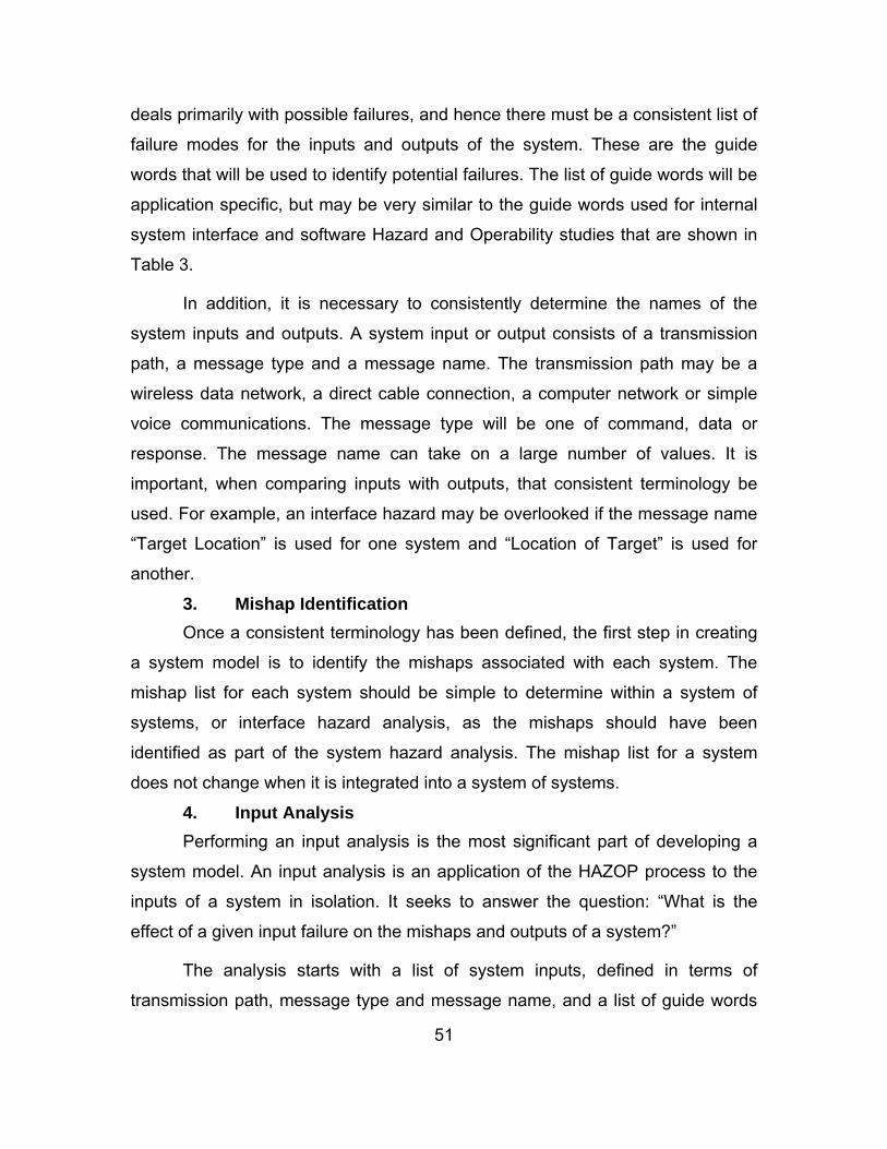
51
deals primarily with possible failures, and hence there must be a consistent list of
failure modes for the inputs and outputs of the system. These are the guide
words that will be used to identify potential failures. The list of guide words will be
application specific, but may be very similar to the guide words used for internal
system interface and software Hazard and Operability studies that are shown in
Table 3.
In addition, it is necessary to consistently determine the names of the
system inputs and outputs. A system input or output consists of a transmission
path, a message type and a message name. The transmission path may be a
wireless data network, a direct cable connection, a computer network or simple
voice communications. The message type will be one of command, data or
response. The message name can take on a large number of values. It is
important, when comparing inputs with outputs, that consistent terminology be
used. For example, an interface hazard may be overlooked if the message name
“Target Location” is used for one system and “Location of Target” is used for
another.
3. Mishap Identification Once a consistent terminology has been defined, the first step in creating
a system model is to identify the mishaps associated with each system. The
mishap list for each system should be simple to determine within a system of
systems, or interface hazard analysis, as the mishaps should have been
identified as part of the system hazard analysis. The mishap list for a system
does not change when it is integrated into a system of systems.
4. Input Analysis Performing an input analysis is the most significant part of developing a
system model. An input analysis is an application of the HAZOP process to the
inputs of a system in isolation. It seeks to answer the question: “What is the
effect of a given input failure on the mishaps and outputs of a system?”
The analysis starts with a list of system inputs, defined in terms of
transmission path, message type and message name, and a list of guide words

52
that describe how an input may fail. Each guide word is applied to each input in
turn, and the effects of that failure on mishaps and outputs assessed. The result
is a list of links, from inputs to outputs or inputs to mishaps. It is of no concern at
this point whether any other system could actually cause the input failure. Each
system must undergo the input analysis process in isolation.
A link can be created between an input and a mishap, as in Figure 18, or
multiple inputs and a mishap, as in Figure 19. While there may be many inputs
within a link, there should only ever be one mishap. If a set of inputs cause more
than one mishap, then a second link, with the same inputs but the alternate
mishap, should be created.
Figure 18. Input to Mishap Link
Figure 19. Multiple Inputs to Mishap Link
In addition to causing mishaps, failed inputs can also cause failed outputs.
A single failed input may cause a single failed output, as in Figure 20, or it may
take more than one failed input to cause a failed output, as in Figure 21.
Alternatively, a single failed input may cause numerous failed outputs, as in
Figure 22. A link must have a single failed input, or a single failed output, or both.

53
If the link involves multiple inputs and multiple outputs, then it can be separated
into two or more links that meet the single input or single output requirement.
Figure 20. Input to Output Link
Figure 21. Multiple Inputs to Single Output Link
Figure 22. Single Input to Multiple Outputs Link
An input analysis generates a list of dependent events, that is, none of the
links that are identified are initiators. They all depend upon other events
transpiring. The events that may trigger one of the links from inputs to outputs, or
from inputs to mishaps, will be generated in the output analysis.

54
5. Output Analysis An output analysis is a HAZOP analysis of the outputs of a system to
determine which system outputs can fail as a result of a system failure, and how
those outputs fail. It uses the same guidewords as the input analysis, and applies
them to each of the system outputs in order to determine whether that type of
failure is possible. A list of system failures that can cause the output failure can
be used to calculate the probability of the output failing, or in developing
mitigation strategies to reduce that probability.
System output failures may occur singly, as in Figure 23, or in groups, as
in Figure 24. System outputs should only be grouped if they are inseparable, that
is, the set of conditions or system failures which causes one output failure
causes every output failure in the group. If it is possible for a subset of the output
failures to occur from the conditions and system failures, then a second group of
system output failures should be created.
Figure 23. Failure to Output Link
Figure 24. Failure to Multiple Outputs Link

55
F. NETWORK ANALYSIS The input analysis and output analysis generates the building blocks for
defining interface hazards. It is clear from the description of the links above that a
link can be drawn from an initiating failure to a mishap. The purpose of a network
analysis is to assemble the links into interface hazards and to ensure that all
possible combinations are assessed. Figure 25 shows how the results of an input
and output analysis can be assembled to form an interface hazard.
Figure 25. Example Interface Hazard Assembled from System Models
The network analysis technique to be used to identify interface hazards is
similar to a Fault Tree Analysis. The analysis starts with an end event, a link from
an input to a mishap, and works backwards, adding links from inputs to outputs
and failures to outputs. The result is a tree that describes all the ways in which an
interface hazard can cause a mishap.
The basic building blocks of a network analysis are shown in Table 5.
These symbols are used instead of the IOM Model as there can be a large
number of elements in the network analysis and the IOM models are
cumbersome.

56
Table 5. Network Analysis Symbology
An example of how these symbols may be used to define an interface
hazard out of the basic elements is shown in Figure 26, which is the symbolic
representation of the interface hazard shown in Figure 25. This is a very simple
example that shows only one way for the mishap to occur. In reality, there may
be many ways for a link to be created between initiating failures and the two
inputs that are required to fail for the mishap to occur. Figure 27 is an example of
how a network analysis tree is more likely to look. Each dashed box represents
the different links which may continue the tree at that point. In this example, there
are ten ways that the mishap can occur. Note that the interface hazard described
by Figure 25 and Figure 26 is also in Figure 27, shown by the option in red.
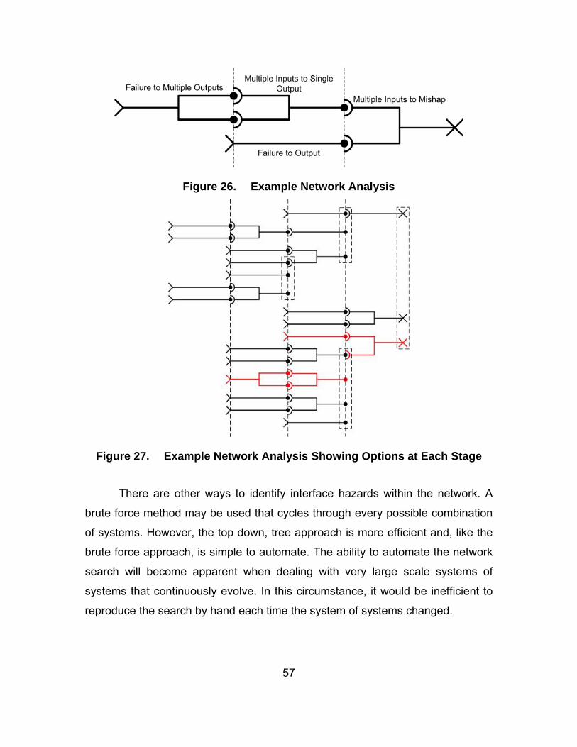
57
Figure 26. Example Network Analysis
Figure 27. Example Network Analysis Showing Options at Each Stage
There are other ways to identify interface hazards within the network. A
brute force method may be used that cycles through every possible combination
of systems. However, the top down, tree approach is more efficient and, like the
brute force approach, is simple to automate. The ability to automate the network
search will become apparent when dealing with very large scale systems of
systems that continuously evolve. In this circumstance, it would be inefficient to
reproduce the search by hand each time the system of systems changed.

58
G. ASSESSMENT OF MISHAP RISK 1. Overview The set of system of systems hazards includes hazards that are identified
by the interface hazard analysis technique and hazards that are identified by
system hazard analysis techniques. The end result is a list of hazards that must
exist in a common database and must be comparable. Hazards that have been
identified by a system hazard analysis technique undergo a mishap risk
assessment, resulting in a statement of the consequence and probability of the
hazard in question. Hazards identified by the interface hazard analysis technique
must have a similar assessment.
2. Consequence The consequence of an interface hazard is the consequence of the
mishap at the top of the network analysis tree. Systems of systems mishaps are
likely to have been identified during the system hazard analysis process for each
individual system and hence the assessment of consequence is also likely to be
already complete.
3. Probability The probability of a interface hazard occurring is a function of the
component elements, that is, the links between inputs and outputs, the links
between inputs and mishaps, and the links between failures and outputs. Each
identified link must be assigned a probability of occurrence. For links between
failures and outputs, this probability is the probability that the failure will occur
and that that failure will translate to an output failure. For links between inputs
and outputs, the probability is the probability that the input failure will be
retransmitted as an output failure. For links between inputs and mishaps, the
probability is the probability that the mishap will occur given that the input failures
have occurred. Each of these probabilities should be assessed qualitatively in
accordance with MIL-STD-882D or a similar safety standard.
Once each link in the interface hazard has been identified, and each link
has been assigned a qualitatively probability, the probability of the interface

59
hazard can be determined by combining all probabilities involved. The
combination of qualitative probabilities is discussed fully in Appendix B, however
the basic principle is to assign a qualitative result to the logical conjunction (i.e.,
the AND function) of two qualitative probabilities, producing a table like that of
Table 6. A two dimensional table is sufficient for all qualitative probability
combinations as the AND function is associative.37
AND Frequent Probable Occasional Remote Improbable
Frequent Frequent Probable Occasional Remote Improbable
Probable Probable Occasional Remote Remote Improbable
Occasional Occasional Remote Remote Improbable Improbable
Remote Remote Remote Improbable Improbable Improbable
Improbable Improbable Improbable Improbable Improbable Improbable
Table 6. Example Qualitative Probability Combinations
Consider the example from Figure 26. Suppose the events in Figure 26
are assessed as having the probabilities shown in Table 7. As each event is
required for the interface hazard to occur, the hazard probability is (using the
qualitative probability combination scheme from Table 6):
As such, the probability of the interface hazard shown in Figure 26 is
Improbable.
37 That is, ( ) ( )a b c a b c a b c× × = × × = × × , or ( ) ( )a b c a b c a b c∧ ∧ = ∧ ∧ = ∧ ∧ .

60
Element Probability
Failure to Multiple Outputs Remote
Multiple Inputs to Single Output Frequent
Failure to Output Occasional
Multiple Inputs to Mishap Frequent
Table 7. Example Event Probabilities for the Interface Hazard from Figure 26.
H. RESIDUAL MISHAP RISK
The residual mishap risk is a significant system of systems factor. It is the
risk that is assumed by the certifying authority and the operators. A system of
systems should never be operated without knowing what the residual mishap risk
is.
A system hazard analysis may have complete system coverage, and as
such, the residual mishap risk can be calculated from the identified risks. A
system of systems hazard analysis is unlikely to have complete coverage. A
hazard analysis for a system of systems, including the interface hazard analysis
technique presented here, is more likely to use a targeted search method that
has a high probability of finding the significant hazards. As such, there will be
unknowns at the completion of the analysis, resulting in some degree of
uncertainty about the actual amount of residual mishap risk.
When dealing with incomplete information, there are three subcategories.
You either have the information (known), you are aware that you do not have
some information (known unknowns), or you are unaware that you do not have
some information (unknown unknowns). In calculating the residual mishap risk
for a system of systems, each of these types of information must be taken into
account. The information that you have should be analyzed. The information that
you do not have, but are aware you do not have, should be assessed as either

61
acceptable or unacceptable to remain unknown. In the latter case, effort should
be made to gain the information. Information that you do not have and do not
know that you do not have should be minimized through the use of a high-quality,
well-funded exploratory process conducted by the appropriate personnel.
Within an interface hazard assessment, the known information is the list of
identified hazards. These hazards can be analyzed to generate an overall risk
assessment for the system of systems in terms of interface hazards. However,
there are two other factors that affect the residual mishap risk. The first is the
interface hazards that are present in the system of systems and are part of the
system models but have not been identified by the network analysis. The second
is the interface hazards that exist in the system of systems that are not identified
because the system models do not accurately represent the systems. The first is
a type of known unknown, the second a type of unknown.
Steps can be taken to minimize the impact of interface hazards that are
part of the system models but not identified by the network analysis. A network
analysis starts with a top-level event, a link from an input to a mishap, and works
backwards to determine the events that can cause that mishap. As each new
event is added to the tree, the probability that the hazard will occur decreases.
As such, at a given level of decomposition, an assessment can be made about
all interface hazards that occur beyond that level of decomposition. This
assessment will depend upon the qualitative probability combination scheme that
is chosen by the analyst.
Consider a qualitative probability combination table that has the result of
the combination of two frequent events as less than frequent (e.g., Table 21 or
Table 22). The worst-case scenario for an interface hazard with five elements is
a direct chain of events, like that shown in Figure 28. The probability of this
hazard is improbable. If you add another event to the left of this chain, the
probability is still improbable. In fact regardless of how many events you add to
the left of this chain, the probability will always be improbable. In addition, if you
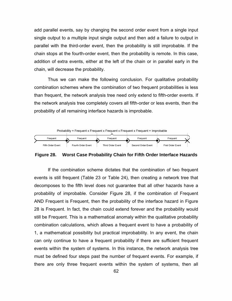
62
add parallel events, say by changing the second order event from a single input
single output to a multiple input single output and then add a failure to output in
parallel with the third-order event, then the probability is still improbable. If the
chain stops at the fourth-order event, then the probability is remote. In this case,
addition of extra events, either at the left of the chain or in parallel early in the
chain, will decrease the probability.
Thus we can make the following conclusion. For qualitative probability
combination schemes where the combination of two frequent probabilities is less
than frequent, the network analysis tree need only extend to fifth-order events. If
the network analysis tree completely covers all fifth-order or less events, then the
probability of all remaining interface hazards is improbable.
Figure 28. Worst Case Probability Chain for Fifth Order Interface Hazards
If the combination scheme dictates that the combination of two frequent
events is still frequent (Table 23 or Table 24), then creating a network tree that
decomposes to the fifth level does not guarantee that all other hazards have a
probability of improbable. Consider Figure 28, if the combination of Frequent
AND Frequent is Frequent, then the probability of the interface hazard in Figure
28 is Frequent. In fact, the chain could extend forever and the probability would
still be Frequent. This is a mathematical anomaly within the qualitative probability
combination calculations, which allows a frequent event to have a probability of
1, a mathematical possibility but practical improbability. In any event, the chain
can only continue to have a frequent probability if there are sufficient frequent
events within the system of systems. In this instance, the network analysis tree
must be defined four steps past the number of frequent events. For example, if
there are only three frequent events within the system of systems, then all

63
interface hazards that extend past the seventh order will have probabilities of
improbable. That is, in the worst-case scenario, the three frequent events will
combine to form a chain whose probability is still frequent. Four more events will
ensure that this probability is reduced to improbable.
The above assumptions, regarding interface hazards beyond a certain
order, refer only to the interface hazards that remain unidentified due to the
network analysis. There are other interface hazards that may remain unidentified
because of shortfalls in the system models. Regardless of how deep or thorough
the network analysis is, these interface hazards will never be identified. These
are the unknown unknowns, and they must be minimized. In order to minimize
the likelihood of overlooking interface hazards in this manner, the development of
the system models must be thorough. This involves a combination of ensuring
that the engineers who perform the analyses are experienced and
knowledgeable, the list of guide words is appropriate for the application and all
aspects of the system inputs and outputs are considered.
In summary, the residual mishap risk of a system of systems due to
interface hazards is the culmination of the identified risks, the knowledge that all
risks not identified by the network analysis but present in the system models
have a maximum probability and the risks that result from unknown system data.
I. SYSTEMS OF SYSTEMS EVOLUTION Systems of systems evolve over the life cycle. New systems are added,
old ones removed and current systems are modified. In order to remain relevant
and cost effective, a hazard analysis technique must be able to cope with
changes to the system of systems.
The interface hazard analysis technique presented above is able to
address system changes. The system models that are developed during the
input and output analyses are independent of other systems. That is, an input
failure is linked to a mishap regardless of whether there is another system that
can cause the input failure to occur. An output failure is defined regardless of

64
whether there is another system that is susceptible to that failure. In addition, the
process that searches for interface hazards, the network analysis, is automated
and hence requires little effort to rerun.
Thus the interface hazard analysis technique remains relevant throughout
the systems of systems life cycle. In the event of a change to a system or an
addition or removal of a system, only the relevant system model need be altered,
removed or added. All other system models remain the same.
J. CONCLUSION The interface hazard analysis technique has been developed to identify
and assess interface hazards, assess the residual mishap risk of interface
hazards and to track hazards through systems of systems evolution. This
technique will fulfill the shortfalls in the system safety program when applied to
systems of systems.
The technique has several advantages. Firstly, it does not require complex
system models to be developed. A HAZOP analysis of the inputs and outputs of
a system will produce a sufficient system model. The system models can then be
analyzed within a network to produce the interface hazards. The network
analysis is a simple process that can be automated.
Interface hazards are assessed in the same manner as system hazards,
that is, they are assessed in terms of probability and consequence. The
consequence assessment is the same as for system hazards. The probability
assessment involves the combination of the qualitative probabilities of the
component events.
The residual mishap risk associated with interface hazards is a function of
the identified hazards, the hazards not identified by the network analysis (whose
probability is limited) and the hazards not identified due to shortfalls in the system
models. The first two can be qualitatively assessed. The last can be minimized
through an expert application of the interface hazard analysis technique.

65
The interface hazard analysis technique can keep track of interface
hazards throughout the system life cycle, even in the face of significant systems
of systems evolution. The main reason for this is that the system models are
independent of each other. They are developed in isolation from the system of
systems and do not require alteration when new systems are added. In addition,
the network analysis technique is simple to automate, which simplifies repetition
of the analysis.
The interface hazard analysis technique is defined in Appendix A. Now
that the technique has been described, it will be applied to a case study in the
following chapter in order to validate its effectiveness.

66
THIS PAGE INTENTIONALLY LEFT BLANK

67
V. APPLICATION OF TECHNIQUE TO CASE STUDY
A. INTRODUCTION A case study is required to ensure that the interface hazard analysis
technique is able to detect interface hazards. The Ballistic Missile Defense
System will be used to validate the effectiveness of this technique.
In this chapter, the development of a software application that employs the
interface hazard analysis technique will be described. This software application
was developed to prove not only the capabilities of the interface hazard analysis
technique, but also to prove that a software application that employs the
technique was conceptually feasible.
The software application will then be applied to the Ballistic Missile
Defense System and interface hazards generated. An overview of the Ballistic
Missile Defense System is provided in Appendix C. Representative data will be
used to generate system models for the Ballistic Missile Defense System and the
case study will be kept sufficiently small to conform to the time constraints of
postgraduate research. The intent is that the case study will further confirm the
feasibility of the interface hazard analysis technique and the corresponding
software.
B. SOFTWARE DEVELOPMENT 1. Overview In order to validate that the interface hazard analysis technique was
practical and capable of producing results, a software application was developed.
The application was built as a concept demonstrator. It allows the user to enter
system models and then performs a network analysis. While it performs the
function of an interface hazard analysis, it is not intended to be used in practice.
It does not include the usual level of error checking and user functions that would
be expected of an application of this type. It’s purpose is to demonstrate that the
interface hazard analysis technique described above is feasible.

68
2. Functional Requirements The software application was designed in order to meet the following basic
requirements:
(i) the application shall allow the user to enter the system model data, (ii) the application shall perform a network analysis on the system
model data, (iii) the application shall display the interface hazards found during the
network analysis to the user, and (iv) the application shall allow changes to the system model data to
simulate the evolution of a system of systems. 3. Design The application was developed in Java and employs a GUI to allow the
user to enter the system model data and to display the identified interface
hazards. The core of the application is the object orientated modeling of a system
of systems and the functions that perform the network analysis. The object
orientated model of a system of systems is shown in Figure 29.
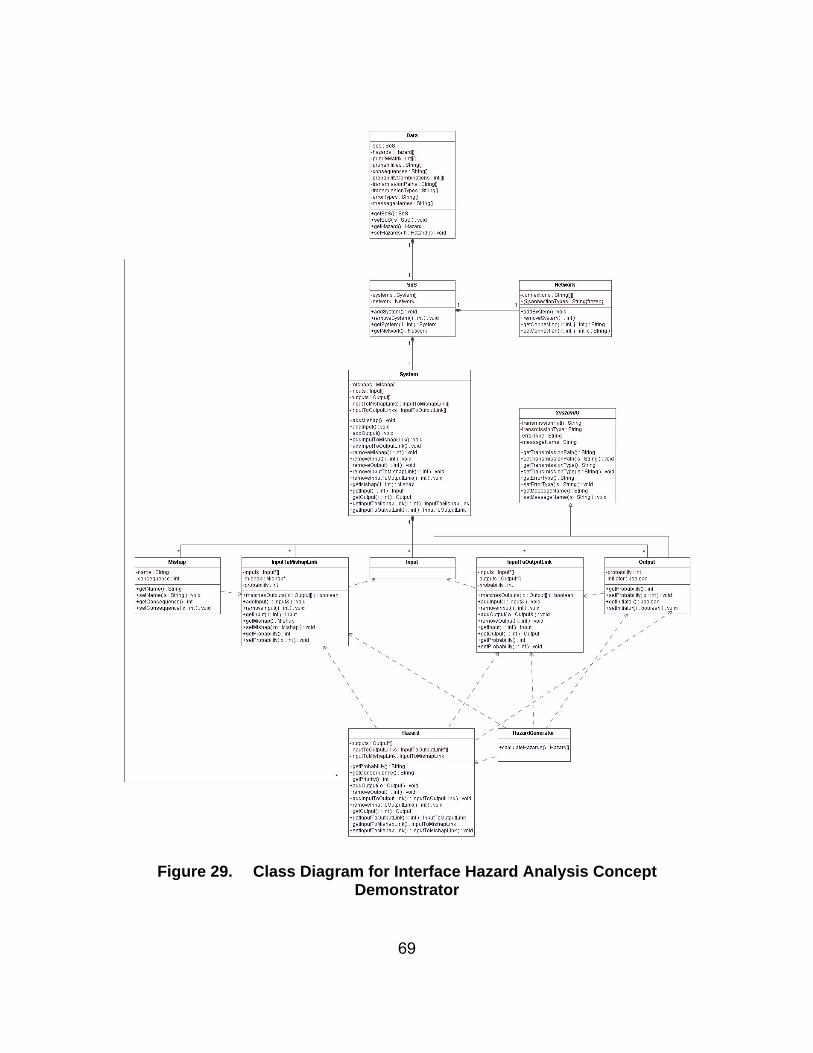
69
Figure 29. Class Diagram for Interface Hazard Analysis Concept Demonstrator

70
The model of the system of systems follows the real world structure. The
highest level object is a data object that contains a number of application settings
and the main system of systems object. Within the system of systems object
there is an array of systems and a network object. The purpose of the network
object is to track the types of connections that exist between systems. Each
system object represents a system that may be present in the system of
systems.
The system object is an implementation of the IOM model. It consists of
mishaps, inputs, outputs, links from inputs to outputs and links from inputs to
mishaps. These are the pieces that will later be constructed into network analysis
trees. The inputs, outputs and mishaps are objects that represent the real world
nature of the systems. The links are simulations of the real world systems
performance. They contain the pointers38 to inputs, outputs and mishaps
necessary to describe the links as well as a value that represents the probability
that the link will occur. Outputs come in two forms; they may either be used later
in a system link or as an initiating event.
A separate hazard generating object is used to perform the network
analysis. It creates hazard objects that contain pointers to the links and outputs
that describe the hazard. A hazard object is able to calculate the hazard
probability, consequence and priority based on its component events. Due to
time constraints, the hazard generating object that was used in the concept
demonstrator employed a brute force algorithm that searched a number of basic
interface hazard schemes. It did not employ a more intelligent and efficient, tree
structured search algorithm. Such an algorithm is not a particularly complex task,
and its generation was not considered necessary to demonstrate the concept.
38 In Java, this is of little consequence as all object references are pointers. However, this
may make a difference if the application is implemented in another language.

71
The GUI used a relatively simple set of text boxes, drop down boxes and
check boxes in order to collect the system model data. The data is stored within
its own object and may be written to an XML file for later restoration. An example
of the application GUI is shown in Figure 30. This example is typical of the
application and is used to collect the input to output links for each system model.
Figure 30. Interface Hazard Analysis Application Screen Shot – GUI
The application also includes interfaces to collect the following data:
(i) Analysis settings such as the qualitative probability levels, the consequence levels, the calculation of priority from probability and consequence, and the combination of two qualitative probabilities.
(ii) A complete list of systems within the system of systems. (iii) A system architecture table.

72
(iv) A list of mishaps for each system. (v) System Input/Output settings such as the transmission paths, the
message types, the message names and the guide words or error types. All are customizable.
(vi) A list of inputs for each system. (vii) A list of outputs for each system, including those that can initiate an
interface hazard. (viii) A list of links from inputs to outputs for each system. (viii) A list of links from inputs to mishaps for each system. In addition, the application displays the results of the network analysis to
the user through both text and graphics. A screen shot of the hazard display is
shown in Figure 31.

73
Figure 31. Interface Hazard Analysis Application Screen Shot – Hazard Display
Overall, the interface hazard analysis application is not a particularly
complex application. The majority of the application deals with data entry and
storage. The application was developed over a period of two months and
consists of approximately 5,500 lines of code. Although its operation was
successfully verified with test data, the application will also be tested on the
Ballistic Missile Defense System case study.
C. SYSTEM OF SYSTEMS HAZARD ANALYSIS 1. Overview The Ballistic Missile Defense System employs systems of systems
technology to achieve a complex mission within a hazardous environment and as

74
such, is ideal for validating the interface hazard analysis technique. The data that
will be used to perform this validation has been generated from the functional
roles of the systems that comprise the system of systems and may or may not be
representative of actual system performance. In addition, the system data has
been simplified to reduce the time taken to perform the analysis to a manageable
level. Neither of these facts affects the validity of the case study.
2. System of Systems Architecture The systems that comprise the system of systems are shown in Table 8.
Symbol System Role
S1 Aegis Destroyer Sensor and Weapon System
S2 Airborne Laser Sensor and Weapon System
S3 Command and Control Center CandC
S4 Forward-based X-Band Radar Sensor
S5 Ground-based Midcourse Interceptors Weapon
S6 Kinetic Energy Interceptors Weapon
S7 Multiple Kill Vehicles Weapon
S8 Patriot Advanced Capability-3 Weapon
S9 Sea-based X-Band Radar Sensor
S10 Space-based Sensors Sensor
S11 Terminal High Altitude Area Defense Weapon
Table 8. Ballistic Missile Defense System Component Systems
These systems interact as shown in Table 9.
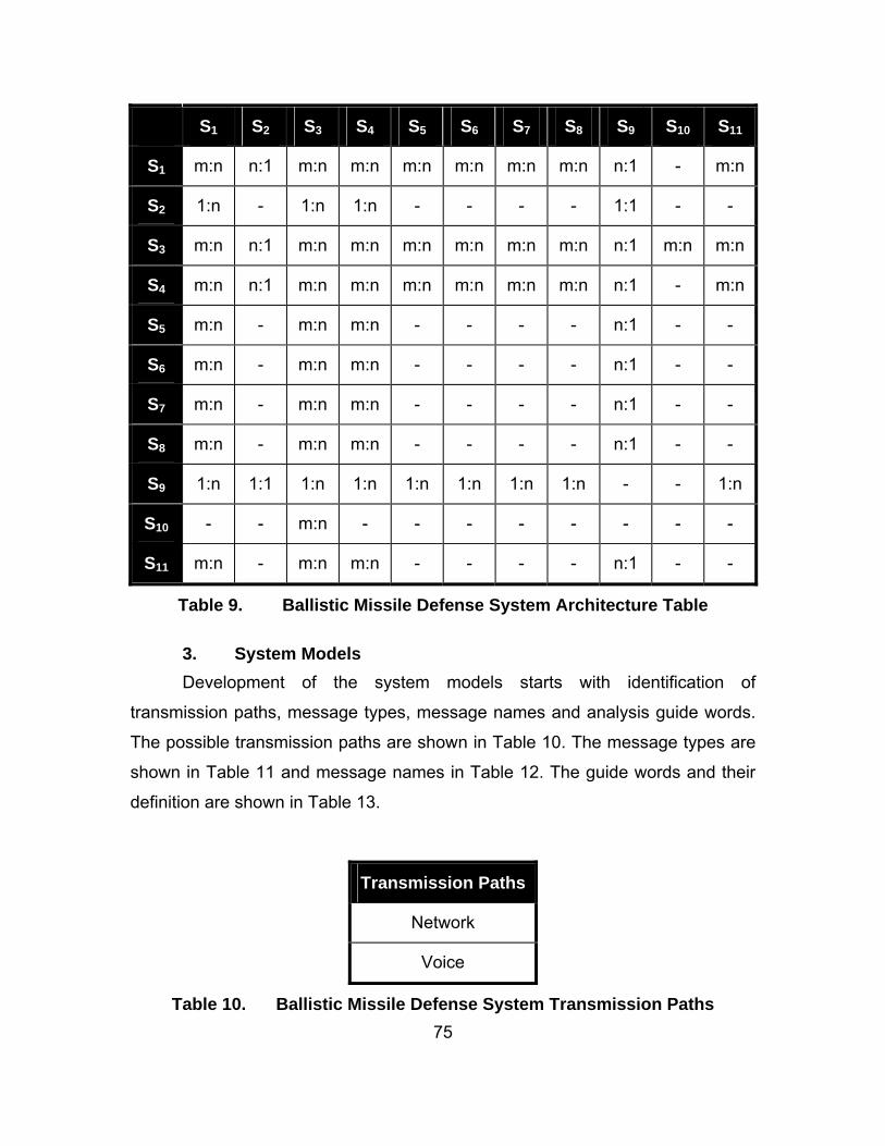
75
S1 S2 S3 S4 S5 S6 S7 S8 S9 S10 S11
S1 m:n n:1 m:n m:n m:n m:n m:n m:n n:1 - m:n
S2 1:n - 1:n 1:n - - - - 1:1 - -
S3 m:n n:1 m:n m:n m:n m:n m:n m:n n:1 m:n m:n
S4 m:n n:1 m:n m:n m:n m:n m:n m:n n:1 - m:n
S5 m:n - m:n m:n - - - - n:1 - -
S6 m:n - m:n m:n - - - - n:1 - -
S7 m:n - m:n m:n - - - - n:1 - -
S8 m:n - m:n m:n - - - - n:1 - -
S9 1:n 1:1 1:n 1:n 1:n 1:n 1:n 1:n - - 1:n
S10 - - m:n - - - - - - - -
S11 m:n - m:n m:n - - - - n:1 - -
Table 9. Ballistic Missile Defense System Architecture Table
3. System Models Development of the system models starts with identification of
transmission paths, message types, message names and analysis guide words.
The possible transmission paths are shown in Table 10. The message types are
shown in Table 11 and message names in Table 12. The guide words and their
definition are shown in Table 13.
Transmission Paths
Network
Voice
Table 10. Ballistic Missile Defense System Transmission Paths

76
Message Types
Command
Data
Response
Table 11. Ballistic Missile Defense System Message Types
Message Names Message Meaning
Cue Command a sensor system to track a target
Fire Command a weapon system to fire on a target
System Location The geographic location of the transmitting system
System Status The status of the transmitting system
Target Detected Communicate that a target has been detected
Target Track A data set that describes the ballistic path of a target
Target Type The type of target that has been detected
Table 12. Ballistic Missile Defense System Message Names

77
Guide Word Meaning
None Intended result not achieved.
More Too much of some parameter.
Less Not enough of a parameter.
As Well As Unintended activity or material.
Part Of Parts of the parameter are missing.
Reverse Value is opposite of intended value.
Other Than Something other than intended result happens.
Omission Intended output missing.
Commission Unintended output.
Early Output occurs too soon.
Late Output occurs too late.
Coarse Incorrect Output’s value is wrong.
Subtle Incorrect Output’s value is wrong, but cannot be detected.
Table 13. Guide Words for Input and Output Analysis
The next step is to define a list of mishaps for all systems. These mishaps
can be obtained from the system hazard analysis. An example mishap list for the
Aegis Destroyer is shown in Table 14. The complete list for all systems is shown
in Appendix D, Table 25.

78
System Mishap Consequence
Radiation causes harm to
personnel
Critical
Radiation causes harm to
property
Critical
Missile exhaust causes harm to
personnel
Critical
Missile impacts friendly system Catastrophic
Missile impacts friendly building Catastrophic
Missile impacts friendly terrain Marginal
Aegis Destroyer
Missile impacts hostile terrain Negligible
Table 14. Mishap List for the Aegis Destroyer
The inputs and outputs for each system are shown in Appendix D Table
26 and Table 27, respectively. This data can be collected from system design
documentation (such as Interface Design Descriptions) and the system of
systems network specification. For the purposes of an input or output analysis, it
is necessary to collate this data into a single, usable source so that each input or
output can be systematically analyzed using the guide words. Note that the
inputs and outputs are formed from the defined transmission paths, message
types and message names.
Once the system inputs and the guide words have been defined, the input
analysis can be performed. For each system input, apply each guide word and
determine the effects on system mishaps and outputs. For example, within the
Forward-based X-Band Radar System, the input “Network Data Cue” and the
guide word “None” combine to form the input failure “Network Data Cue None”.
This type of input failure does not cause a system mishap, nor does it cause a

79
system output to fail. However, the same input, when combined with the
“Commission” guide word may lead to a system mishap if the cueing of the radar
system causes personnel in front of the antenna to be exposed to radiation. The
result of this is a link from the input “Network Data Cue Commission” to the
mishap “Radiation Causes Harm to Personnel”. Within the Command and
Control System, the input “Network Data Target Track” combined with the guide
word “Subtle Incorrect” leads to a dependent output failure “Network Data Target
Track Subtle Incorrect”. This is a link from an input to an output. The full list of
system input to mishap and input to output links are shown in Appendix D Table
28 through Table 42. Together, these tables describe the system models for
each of the systems within the Ballistic Missile Defense System.
4. Preliminary Hazard List The system model data was entered into the interface hazard analysis
application and a network analysis performed. Note that the application can only
detect a limited number of a interface hazard schemes due to the abridged
version of the network analysis algorithm. From the system model data, the
application detected 364 interface hazards ranging from priority two to priority
twenty. Some selected hazards are shown in Table 15. From these results, it is
clear that the interface hazard analysis technique, and the interface hazard
analysis application, are both capable of detecting interface hazards. The
application should be developed further in order to be usefully applied to a full
scale system of systems.

80
Hazard Probability Consequence Priority
Network Data Target Type Subtle Incorrect failure in Aegis Destroyer
causes Missile Impacts Friendly System mishap in Patriot Advanced Capability-3
Probable Catastrophic 2
Network Data Target Track Subtle Incorrect failure in Forward-based X-Band Radar
causes Missile Impacts Friendly Building mishap in Kinetic Energy Interceptors
Remote Catastrophic 8
Network Data Target Type Subtle Incorrect failure in Airborne Laser
causes Network Data Target Type Subtle Incorrect failure in Command and Control Center
causes Missile Impacts Friendly System mishap in Aegis Destroyer
Remote Catastrophic 8
Network Data Target Detected Commission failure in Airborne Laser
causes Network Command Cue Commission failure in Command and Control Center
causes Radiation Causes Harm to Personnel mishap in Sea-based X-Band Radar
Remote Critical 10
Table 15. Selected Interface Hazards from the Ballistic Missile Defense System Case Study

81
From the analysis, it is clear that the most significant hazard within the
Ballistic Missile Defense System is the incorrect designation of a target as a
threat (Network Data Target Type Subtle Incorrect) when it is in fact a friendly
system. This has occurred on several occasions with the Patriot system that
confused low flying aircraft with cruise missiles. It is possible that the Ballistic
Missile Defense System may misidentify aircraft or rockets carrying a non-
threatening payload (particularly from China or Russia) as a threat. Any resultant
destruction of such a system could be catastrophic. However, it is likely that the
Missile Defense Agency has already taken this into account, and begun to
mitigate the hazard. What the interface hazard analysis does reveal is the large
number of ways in which such a mishap can occur.
5. System of Systems Evolution To demonstrate the ability of the interface hazard analysis technique to
deal with system of systems evolution, a mythical “Advanced Technology
System” was added to the system of systems network. The Advanced
Technology System is a detection system that detects launches of ballistic
missiles. It does not provide track data accurate enough for a launch, it only
detects launches and gives the general location. It interfaces only with the
Command and Control Center and there are a large number of devices. It is a
passive system, and hence there are only minor mishaps associated with it.
In adding the Advanced Technology System to the system of systems,
only its system model was added. None of the other system models were altered
in anyway. The system model consists of just one failed output: Network Data
Target Detected Commission with probability: Remote.
When the network analysis was run again, eighteen extra hazards were
identified. These hazards involved other systems, demonstrating the interface
hazard analysis technique successfully identifies new hazards when new
systems are added without altering current system models. An example hazard is
shown in Table 16.

82
Hazard Probability Consequence Priority
Network Data Target Detected Commission failure in Advanced Technology System
causes Network Command Fire Commission failure in Command and Control Center
causes Missile Exhaust Causes Harm to Personnel failure in Ground-based Midcourse Interceptor
Remote Critical 10
Table 16. Example Hazard following the addition of the Advanced Technology System
D. LESSONS LEARNT
A significant result of this case study is the large number of hazards that
are identified from a relatively small set of systems, each with a restricted set of
inputs and outputs. In particular, a large number of hazards are very similar. This
is due to the types of systems present in the Ballistic Missile Defense System,
which perform the role of a sensor, a weapon or both. The application should be
modified to group similar hazards together to ensure that all hazard types receive
adequate visibility.
In addition, while the generation of a simple, linear system model is not
particularly onerous, the system models can become difficult to generate and
comprehend when dealing with multiple input failures leading to multiple outputs
or mishaps. For example, if there are ten inputs and ten guide words then there
are 100 single input/guide words combinations. When considering two inputs,
there are 9,000 combinations, when considering three, there are 720,000
combinations. This makes it very difficult to ensure that the system models are
complete.

83
E. CONCLUSION Both the interface hazard analysis technique and the interface hazard
analysis application were successful in detecting Ballistic Missile Defense
System interface hazards. Although the application employed a limited network
analysis technique, it was still able to detect a significant number of interface
hazards. The concept of a software application that can detect interface hazards
using the interface hazard analysis technique was successfully demonstrated.
In addition, the interface hazard analysis technique proved both useable
and effective. The system models that were required were not difficult to
generate, even from a basic understanding of the Ballistic Missile Defense
System. The input and output analyses were relatively simple to perform,
although it may be more difficult to identify links that involve multiple inputs or
outputs when the number of inputs and outputs are expanded beyond the
modest set used in this case study.
In all, both the interface hazard analysis technique and the concept of a
software application to employ this technique should be considered effective.

84
THIS PAGE INTENTIONALLY LEFT BLANK

85
VI. CONCLUSION
A. KEY FINDINGS AND ACCOMPLISHMENTS The existence of systems of systems hazards, and in particular emergent
hazards, has been acknowledged since the first systems of systems were
conceived. In this thesis, the types of emergent hazards have been identified and
defined. Systems of systems hazards can be broken down into two main
categories. Single system hazards are those that are attributable to a single
system only and require no system interaction in order to occur, and emergent
hazards are those that require the interaction of two or more systems.
Emergent hazards were the focus of this research. System hazard
analysis techniques are largely unable to identify emergent hazards. New
techniques must be developed to identify and analyze emergent hazards. Before
this can be done, the types of emergent hazards must be further defined. There
are three sub categories of emergent hazards. Reconfiguration hazards are
unique to systems of systems and do not have a parallel within the system
space. They are caused by the transition of a system of systems from one state
to another. Interoperability hazards result from miscommunications. A receiving
system interprets a message or signal in a manner that conflicts with the intent of
the transmitting system. The third subcategory is integration hazards. These
hazards can best be described by the subtypes of the category. There are three
subtypes, interface hazards, resource hazards and proximity hazards. An
interface hazard results from a failure or partial performance in one system
causing a mishap in a second system. A resource hazard occurs when there are
insufficient levels of shared resources to support the systems present, or when
there is a conflict over a certain part of the shared resource. A proximity hazard
occurs when one system causes a mishap in another without using a defined
interface.
The purpose of identifying the types of emergent hazards is to focus the
development of hazard analysis techniques. In this thesis, a process was defined

86
that specifically targets interface hazards. This is a small part of the puzzle. A full
system of systems hazard analysis must address all hazard types. Other
techniques must be used in conjunction with the interface hazard analysis
technique defined in this thesis.
The interface hazard analysis technique is based upon the
Input/Output/Mishap (IOM) system model. The IOM model is an extension of the
more traditional Input/Output (IO) model. An interface hazard consists of not just
inputs and outputs but mishaps as well. The IOM model for a system is a set of
links between inputs and outputs, links between inputs and mishaps, and outputs
that can fail due to a system failure. These three elements can be used to
construct an interface hazard. They form a path for a system failure, which may
otherwise be innocuous, to transfer to another system where it may cause a
mishap.
The interface hazard analysis technique has two important characteristics.
Firstly, the system model is relatively simple and quick to develop. System
models can be extremely complex, and hence expensive to create. A simple but
effective system model is essential to ensure a cost effective hazard analysis.
The IOM model meets this requirement. Additionally, the interface hazard
analysis technique must be able to keep pace with the evolution of the system of
systems. The interface hazard analysis technique achieves this by using system
models that are independent of other systems and an automated search process.
In the event that a system is added, removed or modified, only that system model
needs to be added, removed or modified; all other system models can remain the
same.
The technique also provides methods for assessing mishap risk and
estimating the residual risk. The mishap risk is a function of its component
elements, each of which has its own probability. The probabilities are assessed
qualitatively, and combined using a qualitative probability scheme. The
assessment of risk in this manner allows interface hazards to be compared
directly with hazards identified by other techniques.

87
The size of a system of systems in combination with its virtually infinite
configurations makes it impractical to conduct a complete system of systems
hazard. For interface hazards, the residual mishap risk was assessed by
considering known hazards, limiting the probability of unidentified hazards, and
minimizing unknowns through effective techniques and qualified practitioners.
Finally, a software application was developed for use in proving that the
interface hazard analysis technique is valid. The software application was
developed in a relatively short period of time and was relatively small in nature,
but was successfully applied to the Ballistic Missile Defense System and
successfully identified interface hazards.
B. FUTURE WORK There are two major areas for further research. Firstly, the system of
systems hazard taxonomy is not complete. There are other types of emergent
hazards. This taxonomy needs to be further expanded and defined. The follow on
from this is that techniques must be developed that identify and analyze each of
these hazard types. This thesis proposes a technique for identifying only one
hazard type. At the very least, four more hazard analysis techniques are
required, though it may be possible that one technique could cover more than
one hazard type.
An assumption that was made regarding system of systems hazard
analysis is that the analysis will never provide full coverage. That is, there are
parts of a system of systems that will never be analyzed. Considering that there
will be several hazard analysis techniques, and limited budgets, a decision may
be required to perform one technique and not another. Such a decision should be
based upon an assessment of which technique is most likely to identify the
highest priority hazards. A method for determining the most effective technique
for a given application should also be developed.
The success of the interface hazard analysis technique depends largely
upon the guide words that are used. A robust and proven set of guide words
should be developed to ensure more accurate system models.

88
In addition, while the interface hazard analysis technique is capable of
detecting hazards, this data needs to be integrated into the system safety
requirements traceability matrix.
A promising area of research is the application of formal specifications to
system interfaces.39 These techniques may provide methods for preventing or
resolving system of systems interface hazards.
39 D.S. Caffal, and J.B. Michael, (2005) Formal Methods in a System-of-Systems
Development. IEEE International Conference on Systems, Man and Cybernetics. pp. 1856-1863.

89
APPENDIX A. INTERFACE HAZARD ANALYSIS TECHNIQUE
Figure 32. The Interface Hazard Analysis Technique
Establish System List
1. List all systems that may be part of the system of systems.
Define System of Systems Architecture
2. For each system pair, identify the connection that may occur as one
of:
(i) One to One (1:1)
(ii) One to Many (1:n)
(iii) Many to One (n:1)
(iv) Many to Many (m:n)
Define Guidewords and Network Terminology
3. Define a standardized list of network terminology. Describe all
system inputs and outputs in these terms. The network terminology should
include options for each of the following:

90
(i) Transmission Path40
(ii) Message Type (e.g. data, command)
(iii) Message Name
4. Define a list of guidewords that will be used to assess the inputs
and outputs of a system. The guidewords describe the failures that the inputs
and outputs may suffer. A quality set of guidewords is essential to the success of
the technique.
Define Mishap Lists
5. List all mishaps for each system.
Analyze Inputs
6. List all inputs for each system using the network terminology.
7. For each input, apply each guideword and determine the effect of
the resultant failure on the outputs of the system. Consider multiple inputs as
causes for single output failures and single input failures causing multiple output
failures. If a link can be found, add it to the system model. Assess the probability
of the link occurring. That is, the probability that the output failure occurs given
that the input failure has occurred.
8. For each input, apply each guideword and determine whether the
resultant failure can cause one of the system mishaps. Consider multiple inputs
combining to cause a mishap. If a link can be found, add it to the system model.
Assess the probability of the link occurring, that is, the probability that the mishap
will occur given that the input failure has occurred.
Analyze Outputs
9. For each output, apply each guideword and determine whether the
resultant failure can be caused by a failure within the system. Consider multiple
output failure occurring from a single set of system failures. Add all output
40 All transmission paths must be considered, including in-band paths (e.g., defined interfaces) and out-band paths (e.g., voice communication to subvert system checks).

91
failures to the system model. Assess the probability of the output failure
occurring, that is, the probability of the necessary system failures occurring and
the probability of the system failures leading to the output failure.
Analyze Network
10. For each system, assemble a system model that consists of all
identified:
(i) Links between input failures and outputs failures,
(ii) Links between input failures and mishaps, and
(iii) Output failures caused by internal system failures.
11. Construct a network analysis tree for each link between an input
failure and a mishap. Assemble the tree out of links between input failures and
output failures, and output failures caused by internal system failures. Continue
constructing the tree until all tree branches terminate in an output failure caused
by an internal system failure or to sufficient depth such that any hazards that
remain unidentified have a maximum probability that is acceptable.
12. Summarize the network analysis by creating a list of all identified
interface hazards.
Assess Mishap Risk
13. Construct a table that applies the AND function to two qualitative
probability levels.
14. For each identified interface hazard, assess the mishap risk in
terms of probability and consequence. Use the probabilities of the individual
interface hazard elements and the qualitative probability combination table in
order to calculate the overall probability.
92
Assess Residual Mishap Risk
15. Once all risk mitigation activities have been conducted, assess the
residual mishap risk in the system of systems due to interface hazards. Consider
the following in the assessment:
(i) Risk due to identified hazards,
(ii) Risk due to hazards not covered by the extent of the network
trees, and
(iii) Risk due to hazards not identified due to shortfalls in the
system models.
Report Results
10. Link the resultant artifacts from the hazard analysis back to the
system safety requirement traceability matrix.

93
APPENDIX B. QUALITATIVE PROBABILITY COMBINATIONS
The Hazard Analysis process requires that engineers assign a qualitative
value to the likelihood of an events occurrence. When dealing with a System of
Systems, these events can be combined to form a single hazard. The probability
of the hazard is a function of the probabilities of the component events. As each
event is required for the hazard to occur, the probability of the hazard is
assessed using the AND function. This appendix outlines how qualitative
probabilities may be combined using the AND function.
The probability of the hazard is defined as:
P(Hazard) = P(Event1) AND P(Event2) AND … AND P(Eventn)
Each event is assigned a qualitative probability in accordance with
MIL-STD-882D. Qualitative probabilities are used because of the expense and
difficulty of obtaining quantitative probabilities. The purpose of this assessment is
to determine whether relative probability, that is whether one hazard has a higher
probability than another, not absolute probability.
Table 17 shows the qualitative probability levels from MIL-STD-882D.
Columns (I) and (II) are taken directly from MIL-STD-882D. The description of
each level includes a loose mathematical definition. The definition is not
complete because it does not adequately describe the boundaries between
probabilities. For example, it is unclear what the probability level would be for an
event with probability 10-1. Column (III) has been added to indicate the two
methods that can be used to fully define the spectrum of probabilities. A
probability value on the boundary can either be assigned to the higher or lower
probability level. Although the distinction may appear insignificant, a strict
definition is important when combining qualitative probabilities automatically.

94
(I) Name
(II) MIL-STD-882D Definition
(III) Strict Definition
Frequent Likely to occur often within the life of an item, with a probability of occurrence greater than 10-1 in that life.
1 ≥ P > 10-1 or
1 ≥ P ≥ 10-1
Probable Will occur several times within the life of an item, with a probability occurrence less than 10-1 but greater than 10-2 in that life.
10-1 ≥ P > 10-2 or
10-1 > P ≥ 10-2
Occasional Likely to occur sometime in the life of an item, with a probability of occurrence less than 10-2 but greater than 10-3 in that life.
10-2 ≥ P > 10-3 or
10-2 > P ≥ 10-3
Remote Unlikely but possible to occur in the life of an item, with a probability of occurrence less than 10-3 but greater than 10-6 in that life.
10-3 ≥ P > 10-6 or
10-3 > P ≥ 10-6
Improbable So unlikely, it can be assumed occurrence may not be experienced, with a probability of occurrence less than 10-6 in that life.
10-6 ≥ P ≥ 0 or
10-6 > P ≥ 0
Table 17. MIL-STD-882D Mishap Probability Levels41
There are six options for interpreting a qualitative probability numerically in
order to combine with another qualitative probability and then map the result
back to a qualitative probability. Each qualitative probability can be interpreted
either as a worst case scenario, i.e., at the upper limit of the range, or a best
case scenario at the lower limit of the range, or at some point between the two.
When interpreting limits and mapping the result back to a qualitative probability,
the limits can be interpreted conservatively and boundary probabilities assigned
to the higher probability level, or optimistically and boundary probabilities
41 MIL-STD-882D Standard Practice for System Safety (2000) §A.4.4.3.2.2.

95
assigned to the lower probability level. The result of each option is a table that
details the result of applying the AND function to two qualitative probability levels.
For example, using the optimistic interpretation, Frequent AND Probable
results in:
( ) ( )1 1 21 2
1 1 21 2
1 31 2
1 10 10 10
1 10 10 10
10 10
P P
P P
P P
− − −
− − −
− −
≥ > × ≥ >
× ≥ × > ×
≥ × >
Thus, the combination of Frequent AND Probable results in a probability
ranging from, but not including, 10-3 up to and including 10-1. At the low end, a
probability of just greater than 10-3 maps to a qualitative probability level of
Occasional. At the high end, with a probability of 10-1, the probability level is
Probable. This process can be repeated for each interpretation of the
MIL-STD-882D limits to produce the upper and lower bounds shown in Table 18.
In addition to the boundary conditions, a middle value may also be
considered. That is, a value that is equally spaced between the upper and lower
bounds of the probability level. Table 19 shows the middle values that will be
used to analyze the middle ground of qualitative probability combinations. These
middle values are then combined in Table 20. The interpretation of the values in
Table 20 will depend upon whether the MIL-STD-882D limits are interpreted
optimistically or conservatively.

96
Impr
obab
le
10-6
≥ P
≥ 0
or
10-6
> P
≥ 0
10-7
≥ P
≥ 0
or
10-7
> P
≥ 0
10-8
≥ P
≥ 0
or
10-8
> P
≥ 0
10-9
≥ P
≥ 0
or
10-9
> P
≥ 0
10-1
2 ≥ P
≥ 0
or
10-1
2 > P
≥ 0
Rem
ote
10-3
≥ P
> 1
0-7
or
10-3
> P
≥ 1
0-7
10-4
≥ P
> 1
0-8
or
10-4
> P
≥ 1
0-8
10-5
≥ P
> 1
0-9
or
10-5
> P
≥ 1
0-9
10-6
≥ P
> 1
0-12
or
10-6
> P
≥ 1
0-12
10-9
≥ P
≥ 0
or
10-9
> P
≥ 0
Occ
asio
nal
10-2
≥ P
> 1
0-4
or
10-2
> P
≥ 1
0-4
10-3
≥ P
> 1
0-5
or
10-3
> P
≥ 1
0-5
10-4
≥ P
> 1
0-6
or
10-4
> P
≥ 1
0-6
10-5
≥ P
> 1
0-9
or
10-5
> P
≥ 1
0-9
10-8
≥ P
≥ 0
or
10-8
> P
≥ 0
Prob
able
10-1
≥ P
> 1
0-3
or
10-1
> P
≥ 1
0-3
10-2
≥ P
> 1
0-4
or
10-2
> P
≥ 1
0-4
10-3
≥ P
> 1
0-5
or
10-3
> P
≥ 1
0-5
10-4
≥ P
> 1
0-8
or
10-4
> P
≥ 1
0-8
10-7
≥ P
≥ 0
or
10-7
> P
≥ 0
Freq
uent
1 ≥
P >
10-2
or
1 ≥
P ≥
10-2
10-1
≥ P
> 1
0-3
or
10-1
> P
≥ 1
0-3
10-2
≥ P
> 1
0-4
or
10-2
> P
≥ 1
0-4
10-3
≥ P
> 1
0-7
or
10-3
> P
≥ 1
0-7
10-6
≥ P
≥ 0
or
10-6
> P
≥ 0
AN
D
Freq
uent
Prob
able
Occ
asio
nal
Rem
ote
Impr
obab
le
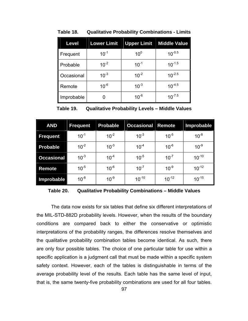
97
Table 18. Qualitative Probability Combinations - Limits
Level Lower Limit Upper Limit Middle Value
Frequent 10-1 100 10-0.5
Probable 10-2 10-1 10-1.5
Occasional 10-3 10-2 10-2.5
Remote 10-6 10-3 10-4.5
Improbable 0 10-6 10-7.5
Table 19. Qualitative Probability Levels – Middle Values
AND Frequent Probable Occasional Remote Improbable
Frequent 10-1 10-2 10-3 10-5 10-8
Probable 10-2 10-3 10-4 10-6 10-9
Occasional 10-3 10-4 10-5 10-7 10-10
Remote 10-5 10-6 10-7 10-9 10-12
Improbable 10-8 10-9 10-10 10-12 10-15
Table 20. Qualitative Probability Combinations – Middle Values
The data now exists for six tables that define six different interpretations of
the MIL-STD-882D probability levels. However, when the results of the boundary
conditions are compared back to either the conservative or optimistic
interpretations of the probability ranges, the differences resolve themselves and
the qualitative probability combination tables become identical. As such, there
are only four possible tables. The choice of one particular table for use within a
specific application is a judgment call that must be made within a specific system
safety context. However, each of the tables is distinguishable in terms of the
average probability level of the results. Each table has the same level of input,
that is, the same twenty-five probability combinations are used for all four tables.

98
The average probabilities of the outputs of each table can then be used to
determine whether one table is more conservative or optimistic than another,
which will aide the choice of table for a specific application. If the application
places a large emphasis on safety, a more conservative table should be chosen.
To compute the average probability, each probability level is assigned a numeric
value (1 for Improbable through 5 for Frequent). The higher the average
probability, the more conservative the table is. The four possible tables are
shown in Table 21 through Table 24 and are shown in order from the most
optimistic to the most conservative.
AND Frequent Probable Occasional Remote Improbable
Frequent Probable Occasional Remote Improbable Improbable
Probable Occasional Remote Remote Improbable Improbable
Occasional Remote Remote Remote Improbable Improbable
Remote Improbable Improbable Improbable Improbable Improbable
Improbable Improbable Improbable Improbable Improbable Improbable
Table 21. Qualitative Probability Combinations – Lower Limit – Average Risk 1.52
AND Frequent Probable Occasional Remote Improbable
Frequent Probable Occasional Remote Remote Improbable
Probable Occasional Remote Remote Improbable Improbable
Occasional Remote Remote Remote Improbable Improbable
Remote Remote Improbable Improbable Improbable Improbable
Improbable Improbable Improbable Improbable Improbable Improbable
Table 22. Qualitative Probability Combinations – Middle Values, Optimistic Interpretation – Average Risk 1.60

99
AND Frequent Probable Occasional Remote Improbable
Frequent Frequent Probable Occasional Remote Improbable
Probable Probable Occasional Remote Remote Improbable
Occasional Occasional Remote Remote Improbable Improbable
Remote Remote Remote Improbable Improbable Improbable
Improbable Improbable Improbable Improbable Improbable Improbable
Table 23. Qualitative Probability Combinations – Middle Values, Conservative Interpretation – Average Risk 1.92
AND Frequent Probable Occasional Remote Improbable
Frequent Frequent Probable Occasional Remote Improbable
Probable Probable Occasional Remote Remote Improbable
Occasional Occasional Remote Remote Remote Improbable
Remote Remote Remote Remote Improbable Improbable
Improbable Improbable Improbable Improbable Improbable Improbable
Table 24. Qualitative Probability Combinations – Upper Limit – Average Risk 2.00

100
THIS PAGE INTENTIONALLY LEFT BLANK

101
APPENDIX C. BALLISTIC MISSILE DEFENSE SYSTEM OVERVIEW
A. OVERVIEW In order to explore the nature of systems of systems hazards and to
validate any hazard analysis techniques in a practical manner, a case study is
required. For the purposes of this research, the Ballistic Missile Defense System
will be used to demonstrate hazard types and to assess hazard analysis
techniques.
The ballistic missile defense program was initiated in 2002 in response to
the threat posed by several developing nations that possessed simple, single
warhead intercontinental ballistic missiles. An evolutionary acquisition strategy
has been employed and the scope of the program has grown to include all types
of ballistic missile threats. The composition of the Ballistic Missile Defense
System will grow and change in the coming years as new systems are acquired
and integrated.
The Ballistic Missile Defense System is a true system of systems. It
employs a variety of systems in a distributed network that cooperate to complete
system of systems goal. The state of the system of systems can change
dynamically as systems either join the network, or depart to perform other roles.
The Ballistic Missile Defense System is arguably the largest, most complex and
most expensive defense program ever undertaken.
B. PURPOSE According to the Missile Defense Agency:
[t]he fundamental objective of the Ballistic Missile Defense program is to develop the capability to defend forces and territories of the United States, its allies and friends against all classes and ranges of ballistic missile threats.42
42 BMD Basics – Overview Retrieved February 27, 2007 from
http://www.mda.mil/mdalink/html/basics.html.

102
The operational concept for the Ballistic Missile Defense System is a
layered defense that provides the capability to strike against ballistic missiles in
the boost, midcourse and terminal phases. At each phase, the commander of the
Ballistic Missile Defense System has several options for destroying the threat
ballistic missile.43 The layered defense structure is shown in Figure 33.
Figure 33. Ballistic Missile Defense System Layered Defense Structure44
Each of the threat missile phases presents different challenges and
advantages. In the boost phase, the missile is at its lowest velocity (it may even
be stationary) and is hence easiest to hit. However, launch sites of the threat
missile can vary greatly geographically and the missile does not remain in the
boost phase for long, requiring an early detection and a rapid response. During
the midcourse phase, the missile is moving significantly faster than during the
boost phase, but the altitude of the missile means that collateral damage is highly
unlikely and hence less discriminate weapons can be used. In the terminal
phase, the missile is moving faster still, but the location of the missile is
geographically restricted to the location of the United States, its allies and their
forces. No phase represents the optimal solution, each has significant
challenges. As such, the Ballistic Missile Defense System aims to engage threat
missiles in all phases of flight.
43 Missile Defense Agency. (2005). A Day in the Life of the BMDS (3rd Ed). 44 After Ibid.

103
C. SYSTEM OF SYSTEMS ARCHITECTURE The architecture of the Ballistic Missile Defense System is fairly simple. It
employs a range of sensors and engagement options that are paired by several
command and control centers. There is no rigid structure, and the network
permits any sensor to be linked to any engagement option. This architecture is
shown in Figure 34.
Figure 34. Ballistic Missile Defense System Architecture
In the architecture shown in Figure 34, there are four sensor systems and
four weapon systems that integrate into the Ballistic Missile Defense System
through two command and control centers. Some weapon systems, Weapon1
and Weapon3, are linked to both command and control centers, the other
systems are linked to only one center. In the example shown, Sensor4 detects

104
the threat missile and notifies CandC1. CandC1 allocates Weapon1 to engage the
threat missile, and creates a link between Weapon1 and Sensor4. This is an
overly simplified example, the threat missile is likely to be detected by several
sensors, and several weapons will be assigned to engage the threat missile (at
least one for each phase of flight), but it serves to show how the Ballistic Missile
Defense System network is created and operates.
D. COMPONENT SYSTEMS 1. Command and Control, Battle Management and
Communications The Command and Control, Battle Management and Communications
element is the backbone of the Ballistic Missile Defense System. Its purpose is to
ensure the flow of critical information between system elements by tracking all
potential ballistic missile threats, directing weapon systems to engage threat
missiles and pairing weapons systems with sensor systems to engage threat
missiles in all phases of flight. The Command and Control, Battle Management
and Communications element consists of four major subsystems: Situational
Awareness, Planner, Battle Management and Network. Together, these
subsystems:
provide the Ballistic Missile Defense System with planning capability to optimally locate sensors and weapon systems to counter identified threats; situational awareness of the evolving battle and status of defensive assets at all leadership levels; sensor netting to detect identify, track and discriminate threats; global integrated fire control to pair the right sensors and weapon systems against multiple threats for the highest probability of kill and to best manage a relatively limited shot magazine; and global communications networks to efficiently manage and distribute essential data.45
45 Missile Defense Agency. (2005). A Day in the Life of the BMDS (3rd Ed), p. 15.

105
Figure 35. Command and Control, Battle Management and Communications Control Center46
2. Aegis Ballistic Missile Defense Aegis destroyers were originally developed to provide a forward air to
surface capability for the protection of aircraft carriers, in particular to counter the
air to surface anti-ship missile threat. They have been modified to perform the
role of both sensor and weapon system within the Ballistic Missile Defense
System. A Long Range Surveillance and Track capability is added to Aegis
destroyers to allow Aegis to trigger other Ballistic Missile Defense System
sensors, and to provide track data to ground-based midcourse defense elements.
Aegis destroyers so equipped are forward deployed to extend the battle space
and provide early warning.
In addition to their primary role as sensors, Aegis destroyers can be
outfitted with the Standard Missile-3 which allows them to engage short and
medium range ballistic missiles. This capability is currently considered an
emergency capability only. The role of Aegis is expected to evolve and increase
as new technologies are tested and employed.47
46 Missile Defense Agency. (2005). A Day in the Life of the BMDS (3rd Ed), p. 14. 47 Ibid., p. 17.

106
Figure 36. Aegis Ballistic Missile Defense48
3. Airborne Laser The airborne laser is a megawatt-class, chemical oxygen iodine laser
mounted on a Boeing 747 aircraft that is capable of destroying ballistic missiles
at a distance of several hundred kilometers. The airborne laser engages threat
ballistic missiles in the boost phase only. In addition to its engagement capability,
the airborne laser also carries six infrared sensors that are used to detect the
heat plume from a ballistic missile launch. The airborne laser is also capable of
receiving target coordinates from the command and control centers. At the time
of writing, the laser had been successfully fired to sufficient power and duration
on the ground, and the aircraft platform with the laser controls and sensors has
been successfully test flown, but the full system has not been tested.49
48 From Program Images Retrieved February 27, 2007 from
http://www.mda.mil/mdalink/html/nmdimg.html#fm6.ANC. 49 Missile Defense Agency. (2005). A Day in the Life of the BMDS (3rd Ed), p. 19.

107
Figure 37. Airborne Laser50
4. Forward-Based X-Band Radar The Forward-Based X-Band Radar is used to detect ballistic missile
threats and provide precise tracking information to the Ballistic Missile Defense
System. It is able to track ballistic missiles in the boost phase, discriminate
between threat and non-threat projectiles and pass track data to the Ballistic
Missile Defense System for engagement by midcourse and terminal weapon
systems. It can either scan autonomously or be cued by other sensor systems.51
50 From Program Images Retrieved February 27, 2007 from
http://www.mda.mil/mdalink/html/nmdimg.html#fm6.ANC. 51 Missile Defense Agency. (2005). A Day in the Life of the BMDS (3rd Ed), p. 21.

108
Figure 38. Forward-Based X-Band Radar52
5. Ballistic Missile Defense System Space Systems The Ballistic Missile Defense System will employ several space-based
sensors, though this capability is limited at present. The intent of the space
systems sensors is to employ infrared and optical sensors to track ballistic
missile threats through all phases of flight and to hand off track data to command
and control elements for threat missile engagement. In addition, the Missile
Defense Agency is currently exploring the economic feasibility of deploying a
space-based interceptor. Such a weapon would not be limited by geography like
land, sea and air-based interceptors.53
6. Ground-based Midcourse Defense The ground-based midcourse defense system is designed to detect, track
and engage intermediate and long range ballistic missiles in the midcourse
phase of flight. Unlike other Ballistic Missile Defense System elements, the
ground-based midcourse defense element is a command and control center,
sensor and weapon system. It is able to engage ballistic missile threats without
the support of the remaining elements, or it can provide sensor and weapon
options to the larger system of systems. The ground-based midcourse defense 52 From Missile Defense Agency. (2005). A Day in the Life of the BMDS (3rd Ed), p. 20. 53 Ibid., p. 23.

109
element utilizes other system sensors as well as adding a sea-based X-band
radar. A ground-based interceptor is used to engage ballistic missiles in the
midcourse phase at high altitudes and speeds. The booster places an
exoatmospheric kill vehicle on a collision path with the threat missile. The kill
vehicle uses kinetic energy to destroy the incoming threat.54
7. Terminal High Altitude Area Defense The Terminal High Altitude Area Defense element provides a regional
defense against threat ballistic missiles. It receives tracking data from the
Ballistic Missile Defense System and is capable of launching a kinetic energy kill
vehicle that can destroy ballistic missiles in all phases of flight, either within or
just outside the atmosphere. The Terminal High Altitude Area Defense element
also tracks the threat missile and guides the kill vehicle to impact.55
Figure 39. Terminal High Altitude Area Defense56
8. Multiple Kill Vehicles Multiple kill vehicles are designed specifically to counter the threat of
ballistic missiles with multiple, independent re-entry vehicles. A multiple kill
54 Missile Defense Agency. (2005). A Day in the Life of the BMDS (3rd Ed), p. 25. 55 Ibid., p. 27. 56 From Program Images Retrieved February 27, 2007 from
http://www.mda.mil/mdalink/html/nmdimg.html#fm6.ANC.

110
vehicle is a carrier vehicle that boosts several kill vehicles into orbit in order to
engage threat missiles in the midcourse phase of flight. Each kill vehicle is
independently targeted and the carrier vehicle has the ability to assign targets to
kill vehicles in flight. It is intended that multiple kill vehicles will be compatible with
the ground-based midcourse defense boosters and potentially the Standard
Missile-3. Multiple kill vehicles rely on the Ballistic Missile Defense System for
target track data.57
9. Patriot Advanced Capability-3 The Patriot Advanced Capability-3 missile system is a terminal defense
weapon that provides a regional defense against ballistic missiles in the terminal
phase of flight. The Patriot system has been successfully employed in operations
in the Middle East. Patriot will be used to defend mobile and forward deployed
forces. It relies on the Ballistic Missile Defense System for threat detection, but is
able to track threat missiles that are in range of its radars.58
10. Kinetic Energy Interceptors Although not yet developed, the purpose of the kinetic energy interceptor
program is to develop next generation, kinetic energy kill vehicles that can
engage threat ballistic missiles in the boost and midcourse phases of flight.
Kinetic energy interceptors will be both land and sea-based and will integrate
with current and future delivery platforms.59
E. SYSTEM EVOLUTION The Missile Defense Agency has employed an evolutionary acquisition
model in the development of the Ballistic Missile Defense System. After the initial
acquisition of core components, block upgrades are performed on a two year
cycle. Each block has a specific scope for upgrading the Ballistic Missile Defense
System capability.60 The scope, functions and hazards of the Ballistic Missile
Defense System, as a system of systems, will change over time. Any hazard
57 Missile Defense Agency. (2005). A Day in the Life of the BMDS (3rd Ed), p. 29. 58 Ibid., p. 31. 59 Ibid., p. 33. 60 Ibid., p. 9.
111
analysis technique must be capable of keeping pace with the evolution of the
system of systems and provide an economical method for updating the safety
assessment.

112
THIS PAGE INTENTIONALLY LEFT BLANK

113
APPENDIX D. BALLISTIC MISSILE DEFENSE SYSTEM CASE STUDY DATA
The following tables contain attribute values developed by the author. The
values do not necessarily correspond to those values assigned by the Missile
Defense Agency.
System Mishap Consequence
Radiation causes harm to
personnel
Critical
Radiation causes harm to
property
Critical
Missile exhaust causes harm to
personnel
Critical
Missile impacts friendly system Catastrophic
Missile impacts friendly building Catastrophic
Missile impacts friendly terrain Marginal
Aegis Destroyer
Missile impacts hostile terrain Negligible61
Laser destroys friendly system Catastrophic
Laser radiates friendly system Critical
Airborne Laser
Laser radiates friendly building Critical
Radiation causes harm to
personnel
Critical Forward-based X-Band
Radar
Radiation causes harm to
property
Critical
61 This is not just an operational mishap. Damage to hostile property and personnel fall within
the purview of operational hazards, however, the impact could also cause environmental damage and hence must be considered a system safety mishap.

114
System Mishap Consequence
Missile exhaust causes harm to
personnel
Critical
Missile impacts friendly system Catastrophic
Missile impacts friendly building Catastrophic
Missile impacts friendly terrain Marginal
Ground-based Midcourse
Interceptors
Missile impacts hostile terrain Negligible
Missile exhaust causes harm to
personnel
Critical
Missile impacts friendly system Catastrophic
Missile impacts friendly building Catastrophic
Missile impacts friendly terrain Negligible
Kinetic Energy
Interceptor
Missile impacts hostile terrain Negligible
Multiple Kill Vehicles Missile exhaust causes harm to
personnel
Critical
Missile exhaust causes harm to
personnel
Critical
Missile impacts friendly system Catastrophic
Missile impacts friendly building Catastrophic
Missile impacts friendly terrain Marginal
Patriot Advanced
Capability-3
Missile impacts hostile terrain Negligible

115
System Mishap Consequence
Radiation causes harm to
personnel
Critical Sea-based X-Band
Radar
Radiation causes harm to
property
Critical
Missile exhaust causes harm to
personnel
Critical
Missile impacts friendly system Catastrophic
Missile impacts friendly building Catastrophic
Missile impacts friendly terrain Marginal
Terminal High Altitude
Area Defense
Missile impacts hostile terrain Negligible
Table 25. Ballistic Missile Defense System Component System Mishaps

116
System Input
Network Command Cue
Network Command Fire
Network Data Target Track
Network Data Target Type
Aegis Destroyer
Voice Command Fire
Network Command Fire
Network Data Target Track
Network Data Target Type
Airborne Laser
Voice Command Fire
Network Data System Location
Network Data System Status
Network Data Target Detected
Network Data Target Track
Network Data Target Type
Command and Control Center
Voice Data Target Detected
Network Command Cue
Network Data Target Track
Forward-based X-Band Radar
Network Data Target Type
Network Command Fire
Network Data Target Track
Ground-based Midcourse Interceptor
Network Data Target Type

117
System Input
Voice Command Fire
Network Command Fire
Network Data Target Track
Network Data Target Type
Kinetic Energy Interceptors
Voice Command Fire
Network Command Fire
Network Data Target Track
Network Data Target Type
Multiple Kill Vehicles
Voice Command Fire
Network Command Fire
Network Data Target Track
Network Data Target Type
Patriot Advanced Capability-3
Voice Command Fire
Network Command Cue
Network Data Target Track
Sea-based X-Band Radar
Network Data Target Type
Network Command Cue
Network Data Target Track
Space-based Sensors
Network Data Target Type
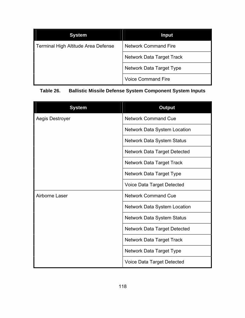
118
System Input
Network Command Fire
Network Data Target Track
Network Data Target Type
Terminal High Altitude Area Defense
Voice Command Fire
Table 26. Ballistic Missile Defense System Component System Inputs
System Output
Network Command Cue
Network Data System Location
Network Data System Status
Network Data Target Detected
Network Data Target Track
Network Data Target Type
Aegis Destroyer
Voice Data Target Detected
Network Command Cue
Network Data System Location
Network Data System Status
Network Data Target Detected
Network Data Target Track
Network Data Target Type
Airborne Laser
Voice Data Target Detected

119
System Output
Network Command Cue
Network Command Fire
Network Data Target Detected
Network Data Target Track
Network Data Target Type
Command and Control Center
Voice Command Fire
Network Command Cue
Network Data System Location
Network Data System Status
Network Data Target Detected
Network Data Target Track
Network Data Target Type
Forward-based X-Band Radar
Voice Data Target Detected
Network Data System Location Ground-based Midcourse Interceptors
Network Data System Status
Network Data System Location Kinetic Energy Interceptors
Network Data System Status
Network Data System Location Multiple Kill Vehicles
Network Data System Status
Network Data System Location Patriot Advanced Capability-3
Network Data System Status

120
System Output
Network Command Cue
Network Data System Location
Network Data System Status
Network Data Target Detected
Network Data Target Track
Network Data Target Type
Sea-based X-Band Radar
Voice Data Target Detected
Network Command Cue
Network Data System Location
Network Data System Status
Network Data Target Detected
Network Data Target Track
Space-based Sensors
Network Data Target Type
Network Data System Location Terminal High Altitude Area Defense
Network Data System Status
Table 27. Ballistic Missile Defense System Component Systems Outputs

121
Input Mishap Probability
Network Command Cue
Commission
Radiation Causes Harm to
Personnel
Remote
Network Command Cue
Commission
Radiation Causes Harm to
Property
Remote
Network Command Fire
Commission
Missile Exhaust Causes Harm
to Personnel
Occasional
Network Data Target Track
Subtle Incorrect
Missile Impacts Friendly
Building
Improbable
Network Data Target Track
Subtle Incorrect
Missile Impacts Friendly
Terrain
Remote
Network Data Target Track
Subtle Incorrect
Missile Impacts Hostile Terrain Probable
Network Data Target Type
Subtle Incorrect
Missile Impacts Friendly
System
Probable
Voice Command Fire
Commission
Missile Exhaust Causes Harm
to Personnel
Remote
Table 28. Aegis Destroyer Links from Input to Mishap

122
Output Probability
Network Command Cue Commission Remote
Network Data System Location Subtle Incorrect Occasional
Network Data System Status Subtle Incorrect Remote
Network Data Target Detected Commission Probable
Network Data Target Track Subtle Incorrect Occasional
Network Data Target Type Subtle Incorrect Probable
Voice Data Target Detected Commission Occasional
Table 29. Aegis Destroyer Failed Outputs
Input Mishap Probability
Network Data Target Track Subtle Incorrect
Laser radiates friendly system Remote
Network Data Target Track Subtle Incorrect
Laser radiates friendly building Remote
Network Data Target Type Subtle Incorrect
Laser destroys friendly system Probable
Table 30. Airborne Laser Links from Input to Mishap

123
Output Probability
Network Command Cue Commission Remote
Network Data System Location Subtle Incorrect Occasional
Network Data System Status Subtle Incorrect Remote
Network Data Target Detected Commission Remote
Network Data Target Track Subtle Incorrect Occasional
Network Data Target Type Subtle Incorrect Remote
Voice Data Target Detected Commission Improbable
Table 31. Airborne Laser Failed Outputs

124
Input Output Probability
Network Data Target Detected Commission
Network Command Cue Commission
Probable
Network Data Target Detected Commission
Network Command Fire Commission
Occasional
Network Data Target Detected Commission
Voice Command Fire Commission
Remote
Network Data Target Track Subtle Incorrect
Network Data Target Track Subtle Incorrect
Frequent
Network Data Target Type Subtle Incorrect
Network Data Target Type Subtle Incorrect
Probable
Voice Data Target Detected Commission
Network Command Cue Commission
Frequent
Voice Data Target Detected Commission
Network Command Fire Commission
Occasional
Voice Data Target Detected Commission
Voice Command Fire Commission
Occasional
Table 32. Command and Control Center Links from Inputs to Outputs
Input Mishap Probability
Network Command Cue
Commission
Radiation Causes Harm to
Personnel
Remote
Network Command Cue
Commission
Radiation Causes Harm to
Property
Improbable
Table 33. Forward-based X-Band Radar Links from Input to Mishap
Output Probability
Network Command Cue Commission Occasional
Network Data System Location Subtle Incorrect Improbable

125
Network Data System Status Subtle Incorrect Remote
Network Data Target Detected Commission Remote
Network Data Target Track Subtle Incorrect Occasional
Network Data Target Type Subtle Incorrect Occasional
Voice Data Target Detected Commission Remote
Table 34. Forward-based X-Band Radar Failed Outputs

126
Input Mishap Probability
Network Command Fire Commission
Missile Exhaust Causes Harm to Personnel
Occasional
Network Data Target Track Subtle Incorrect
Missile Impacts Friendly Building
Improbable
Network Data Target Track Subtle Incorrect
Missile Impacts Friendly Terrain
Improbable
Network Data Target Track Subtle Incorrect
Missile Impacts Hostile Terrain Improbable
Network Data Target Type Subtle Incorrect
Missile Impacts Friendly System
Probable
Voice Command Fire Commission
Missile Exhaust Causes Harm to Personnel
Occasional
Table 35. Ground-based Midcourse Interceptors Links from Input to Mishap
Input Mishap Probability
Network Command Fire Commission
Missile Exhaust Causes Harm to Personnel
Remote
Network Data Target Track Subtle Incorrect
Missile Impacts Friendly Building
Remote
Network Data Target Track Subtle Incorrect
Missile Impacts Friendly Terrain
Occasional
Network Data Target Track Subtle Incorrect
Missile Impacts Hostile Terrain Occasional
Network Data Target Type Subtle Incorrect
Missile Impacts Friendly System
Occasional
Voice Command Fire Commission
Missile Exhaust Causes Harm to Personnel
Remote
Table 36. Kinetic Energy Interceptors Links from Input to Mishap

127
Input Mishap Probability
Network Command Fire Commission
Missile Exhaust Causes Harm to Personnel
Improbable
Voice Command Fire Commission
Missile Exhaust Causes Harm to Personnel
Remote
Table 37. Multiple Kill Vehicles Links from Input to Mishap
Input Mishap Probability
Network Command Fire Commission
Missile Exhaust Causes Harm to Personnel
Remote
Network Data Target Track Subtle Incorrect
Missile Impacts Friendly Building
Occasional
Network Data Target Track Subtle Incorrect
Missile Impacts Friendly Terrain
Probable
Network Data Target Track Subtle Incorrect
Missile Impacts Hostile Terrain Improbable
Network Data Target Type Subtle Incorrect
Missile Impacts Friendly System
Frequent
Voice Command Fire Commission
Missile Exhaust Causes Harm to Personnel
Occasional
Table 38. Patriot Advanced Capability-3 Links from Input to Mishap
Input Mishap Probability
Network Command Cue
Commission
Radiation Causes Harm to
Personnel
Occasional
Network Command Cue
Commission
Radiation Causes Harm to
Property
Improbable
Table 39. Sea-based X-Band Radar Links from Input to Mishap

128
Output Probability
Network Command Cue Commission Occasional
Network Data System Location Subtle Incorrect Occasional
Network Data System Status Subtle Incorrect Remote
Network Data Target Detected Commission Remote
Network Data Target Track Subtle Incorrect Probable
Network Data Target Type Subtle Incorrect Occasional
Voice Data Target Detected Commission Remote
Table 40. Sea-based X-Band Radar Failed Outputs
Output Probability
Network Command Cue Commission Remote
Network Data System Location Subtle Incorrect Remote
Network Data System Status Subtle Incorrect Remote
Network Data Target Detected Commission Occasional
Network Data Target Track Subtle Incorrect Probable
Network Data Target Type Subtle Incorrect Occasional
Table 41. Space-based Sensors Failed Outputs

129
Input Mishap Probability
Network Command Fire Commission
Missile Exhaust Causes Harm to Personnel
Occasional
Network Data Target Track Subtle Incorrect
Missile Impacts Friendly Building
Occasional
Network Data Target Track Subtle Incorrect
Missile Impacts Friendly Terrain
Probable
Network Data Target Track Subtle Incorrect
Missile Impacts Hostile Terrain Remote
Network Data Target Type Subtle Incorrect
Missile Impacts Friendly System
Occasional
Voice Command Fire Commission
Missile Exhaust Causes Harm to Personnel
Probable
Table 42. Terminal High Altitude Area Defense Links from Input to Mishap

130
THIS PAGE INTENTIONALLY LEFT BLANK

131
LIST OF REFERENCES
A Consensus of the INCOSE Fellows Retrieved February 27, 2007 from http://www.incose.org/practice/fellowsconsensus.aspx.
Alexander, R., and Kelly, T. (2006). Can We Remove the Human from Hazard Analysis?, Proceedings of the 24th International Systems Safety Conference. Unionville, VA, System Safety Society.
Alexander, R., and Kelly, T. (2006). Hazard Analysis through Simulation for Systems of Systems, Proceedings of the 24th International Systems Safety Conference. Unionville, VA, System Safety Society.
Alexander, R., Hall-May, M., and Kelly, T. (2004). Characterisation of Systems of Systems Failures. Proceedings of the 22nd Annual System Safety Conference. Unionville, VA, System Safety Society.
BMD Basics – Overview Retrieved February 27, 2007 from http://www.mda.mil/mdalink/html/basics.html.
Caffal, D.S., and Michael, J.B. (2005) Architectural Framework for a System-of-Systems IEEE International Conference on Systems, Man and Cybernetics pp. 1876-1881.
Caffal, D.S., and Michael, J.B., (2005) Formal Methods in a System-of-Systems Development. IEEE International Conference on Systems, Man and Cybernetics. pp. 1856-1863.
Despotou, G., Alexander, R., and Hall-May, M. (2003). Key Concepts and Characteristics of Systems of Systems, Technical Report DARP/BG/2003/1, University of York, York, United Kingdom.
Ericson, C. (2005). Hazard Analysis Techniques for System Safety, Hoboken, NJ: Wiley-Interscience.
Hall-May, M. and Kelly, T. (2005). Defining and Decomposing Safety Policy for Systems of Systems, Proceedings of the 24th International Conference on Computer Safety, Reliability and Security. In Winther, R., Gran, B.A., and Dahll, G., eds., Lecture Notes in Computer Science, Vol. 3688, Berlin: Springer, pp. 37-51.
Hall-May, M., and Kelly, T. (2005). Planes, Trains and Automobiles – An Investigation into Safety Policy for Systems of Systems, Proceedings of the 23rd International Systems Safety Conference. Unionville, VA, System Safety Society.

132
IEEE 1220-2005 Standard for Application and Management of the Systems Engineering Process (2005).
Leveson, N. (1995) Safeware: System Safety and Computers Boston: Addison Wesley.
Michael, J. B. (2004). Gaining the Trust of Stakeholders in Systems of Systems: A Brief Look at the Ballistic Missile Defense System, Proceedings of the Center for National Software Studies Workshop on Trustworthy Software. In Technical Report NPS-CS-04-006, Dept. of Computer Science, Naval Postgraduate School, Monterey, CA.
Michael, J. B., Nerode, A., and Wijesekera, D. (2006) On the Provision of Safety Assurance via Safety Kernels for Modern Weapon Systems Proceedings of the Fifth Workshop on Software Assessment. In Technical Report NPS-CS-06-008, Dept. of Computer Science, Naval Postgraduate School, Monterey, CA.
MIL-STD-882D Standard Practice for System Safety (2000).
Missile Defense Agency. (2005). A Day in the Life of the BMDS (3rd Ed).
National Aeronautics and Space Administration. (1995). Electronic Systems Failures and Anomalies Attributed to Electromagnetic Interference (NASA-RP-1374). NASA Marshall Space Flight Center.
National Aeronautics and Space Administration. (1999). System Safety Handbook (DHB-S-001) Edwards, CA: Dryden Research Flight Center.
National Aeronautics and Space Administration. (2002). Fault Tree Handbook with Aerospace Applications (Version 1.1) Washington, DC: NASA Office of Safety and Mission Assurance.
Office of Management and Budget. (1995). System Safety Hazard Analysis Report (DI-SAFT-80101B) Washington, DC.
Program Images Retrieved February 27, 2007 from http://www.mda.mil/mdalink/html/nmdimg.html#fm6.ANC.
Reese, J. and Leveson, N. (1997). Software Deviation Analysis Proceedings of the 19th International Conference on Software Engineering pp. 250-260.
133
INITIAL DISTRIBUTION LIST
1. Defense Technical Information Center Ft. Belvoir, Virginia
2. Dudley Knox Library Naval Postgraduate School Monterey, California
3. Arch McKinlay Naval Ordnance Safety and Security Activity Indiana Head, Maryland
4. Mike Brown EG&G Gaithersburg, Maryland
5. John Harauz Jonic Systems Engineering, Inc Willowdale, Ontario, Canada
6. Professor J. Bret Michael Naval Postgraduate School Monterey, California
7. Professor Paul Shebalin Naval Postgraduate School Monterey, California
8. Squadron Leader Derek Reinhardt Royal Australian Air Force RAAF Williams, Laverton, Australia