Embed Size (px)
Citation preview

NAVAL
POSTGRADUATE
SCHOOL
MONTEREY, CALIFORNIA
THESIS
Approved for public release; distribution is unlimited
SOFTWARE-DEFINED RADIO GLOBAL SYSTEM FOR MOBILE COMMUNICATIONS TRANSMITTER
DEVELOPMENT FOR HETEROGENEOUS NETWORK VULNERABILITY TESTING
by
Carson C. McAbee
December 2013
Thesis Co-Advisors: Murali Tummala John McEachen

THIS PAGE INTENTIONALLY LEFT BLANK
i
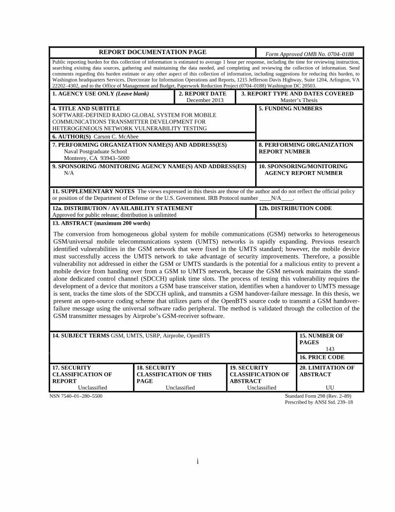
REPORT DOCUMENTATION PAGE Form Approved OMB No. 0704–0188Public reporting burden for this collection of information is estimated to average 1 hour per response, including the time for reviewing instruction, searching existing data sources, gathering and maintaining the data needed, and completing and reviewing the collection of information. Send comments regarding this burden estimate or any other aspect of this collection of information, including suggestions for reducing this burden, to Washington headquarters Services, Directorate for Information Operations and Reports, 1215 Jefferson Davis Highway, Suite 1204, Arlington, VA 22202–4302, and to the Office of Management and Budget, Paperwork Reduction Project (0704–0188) Washington DC 20503.
1. AGENCY USE ONLY (Leave blank)
2. REPORT DATE December 2013
3. REPORT TYPE AND DATES COVERED Master’s Thesis
4. TITLE AND SUBTITLE SOFTWARE-DEFINED RADIO GLOBAL SYSTEM FOR MOBILE COMMUNICATIONS TRANSMITTER DEVELOPMENT FOR HETEROGENEOUS NETWORK VULNERABILITY TESTING
5. FUNDING NUMBERS
6. AUTHOR(S) Carson C. McAbee
7. PERFORMING ORGANIZATION NAME(S) AND ADDRESS(ES) Naval Postgraduate School Monterey, CA 93943–5000
8. PERFORMING ORGANIZATION REPORT NUMBER
9. SPONSORING /MONITORING AGENCY NAME(S) AND ADDRESS(ES) N/A
10. SPONSORING/MONITORING AGENCY REPORT NUMBER
11. SUPPLEMENTARY NOTES The views expressed in this thesis are those of the author and do not reflect the official policy or position of the Department of Defense or the U.S. Government. IRB Protocol number ____N/A____.
12a. DISTRIBUTION / AVAILABILITY STATEMENT Approved for public release; distribution is unlimited
12b. DISTRIBUTION CODE
13. ABSTRACT (maximum 200 words)
The conversion from homogeneous global system for mobile communications (GSM) networks to heterogeneous GSM/universal mobile telecommunications system (UMTS) networks is rapidly expanding. Previous research identified vulnerabilities in the GSM network that were fixed in the UMTS standard; however, the mobile device must successfully access the UMTS network to take advantage of security improvements. Therefore, a possible vulnerability not addressed in either the GSM or UMTS standards is the potential for a malicious entity to prevent a mobile device from handing over from a GSM to UMTS network, because the GSM network maintains the stand-alone dedicated control channel (SDCCH) uplink time slots. The process of testing this vulnerability requires the development of a device that monitors a GSM base transceiver station, identifies when a handover to UMTS message is sent, tracks the time slots of the SDCCH uplink, and transmits a GSM handover-failure message. In this thesis, we present an open-source coding scheme that utilizes parts of the OpenBTS source code to transmit a GSM handover-failure message using the universal software radio peripheral. The method is validated through the collection of the GSM transmitter messages by Airprobe’s GSM-receiver software.
14. SUBJECT TERMS GSM, UMTS, USRP, Airprobe, OpenBTS 15. NUMBER OF
PAGES 143
16. PRICE CODE
17. SECURITY CLASSIFICATION OF REPORT
Unclassified
18. SECURITY CLASSIFICATION OF THIS PAGE
Unclassified
19. SECURITY CLASSIFICATION OF ABSTRACT
Unclassified
20. LIMITATION OF ABSTRACT
UU
NSN 7540–01–280–5500 Standard Form 298 (Rev. 2–89) Prescribed by ANSI Std. 239–18

ii
THIS PAGE INTENTIONALLY LEFT BLANK
iii
Approved for public release; distribution is unlimited
SOFTWARE-DEFINED RADIO GLOBAL SYSTEM FOR MOBILE COMMUNICATIONS TRANSMITTER DEVELOPMENT FOR HETEROGENEOUS NETWORK VULNERABILITY TESTING
Carson C. McAbee
Lieutenant, United States Navy B.S., United States Naval Academy, 2005
Submitted in partial fulfillment of the requirements for the degree of
MASTER OF SCIENCE IN ELECTRICAL ENGINEERING
from the
NAVAL POSTGRADUATE SCHOOL December 2013
Author: Carson C. McAbee
Approved by: Murali Tummala Thesis Co-Advisor
John McEachen Thesis Co-Advisor
R. Clark Robertson Chair, Department of Electrical and Computer Engineering

iv
THIS PAGE INTENTIONALLY LEFT BLANK
v
ABSTRACT
The conversion from homogeneous global system for mobile communications (GSM)
networks to heterogeneous GSM/universal mobile telecommunications system (UMTS)
networks is rapidly expanding. Previous research identified vulnerabilities in the GSM
network that were fixed in the UMTS standard; however, the mobile device must
successfully access the UMTS network to take advantage of security improvements.
Therefore, a possible vulnerability not addressed in either the GSM or UMTS standards is
the potential for a malicious entity to prevent a mobile device from handing over from a
GSM to UMTS network, because the GSM network maintains the stand-alone dedicated
control channel (SDCCH) uplink time slots. The process of testing this vulnerability
requires the development of a device that monitors a GSM base transceiver station,
identifies when a handover to UMTS message is sent, tracks the time slots of the SDCCH
uplink, and transmits a GSM handover-failure message. In this thesis, we present an
open-source coding scheme that utilizes parts of the OpenBTS source code to transmit a
GSM handover-failure message using the universal software radio peripheral. The
method is validated through the collection of the GSM transmitter messages by
Airprobe’s GSM-receiver software.

vi
THIS PAGE INTENTIONALLY LEFT BLANK
vii
TABLE OF CONTENTS
I. INTRODUCTION........................................................................................................1 A. THESIS OBJECTIVE .....................................................................................1 B. RELATED WORK ..........................................................................................2 C. ORGANIZATION ...........................................................................................3
II. GSM VULNERABILITIES AND FUNDAMENTALS ............................................5 A. GSM VULNERABILTIES ..............................................................................5
1. Rogue Base Station ..............................................................................5 2. Weak A5/1 and A5/2 Encryption ........................................................6 3. Solution in UMTS Networks ...............................................................6
B. HANDOVER TO UTRAN ..............................................................................6 1. Handover to UTRAN Messaging ........................................................6 2. Handover Failure Messaging ..............................................................7
C. GSM PHYSICAL AND LOGICAL CHANNELS ........................................9 1. Broadcast Channel (BCH) and Common Control Channel
(CCCH) ...............................................................................................12 2. Stand-Alone Dedicated Control Channel (SDCCH) .......................13
D. GSM MESSAGING .......................................................................................13 1. GSM Layer Three Messaging ...........................................................16 2. GSM Layer Two Messaging ..............................................................16
E. GSM BURST FORMING .............................................................................16 1. Block Coder ........................................................................................16 2. ½-Rate Convolution Encoder ............................................................18 3. Interleaver ..........................................................................................19 4. Burst Mapping ...................................................................................19
F. GSM MODULATION ...................................................................................20 1. Differential Encoder ..........................................................................20 2. GMSK Modulation ............................................................................21
III. GSM TRANSMITTER DESIGN FOR VULNERABILITY TESTING ..............23 A. HANDOVER TO UTRAN VULNERABILITY .........................................23 B. SYSTEM REQUIREMENTS FOR VULNERABILITY TESTING ........24 C. GSM TRANSMITTER ..................................................................................25
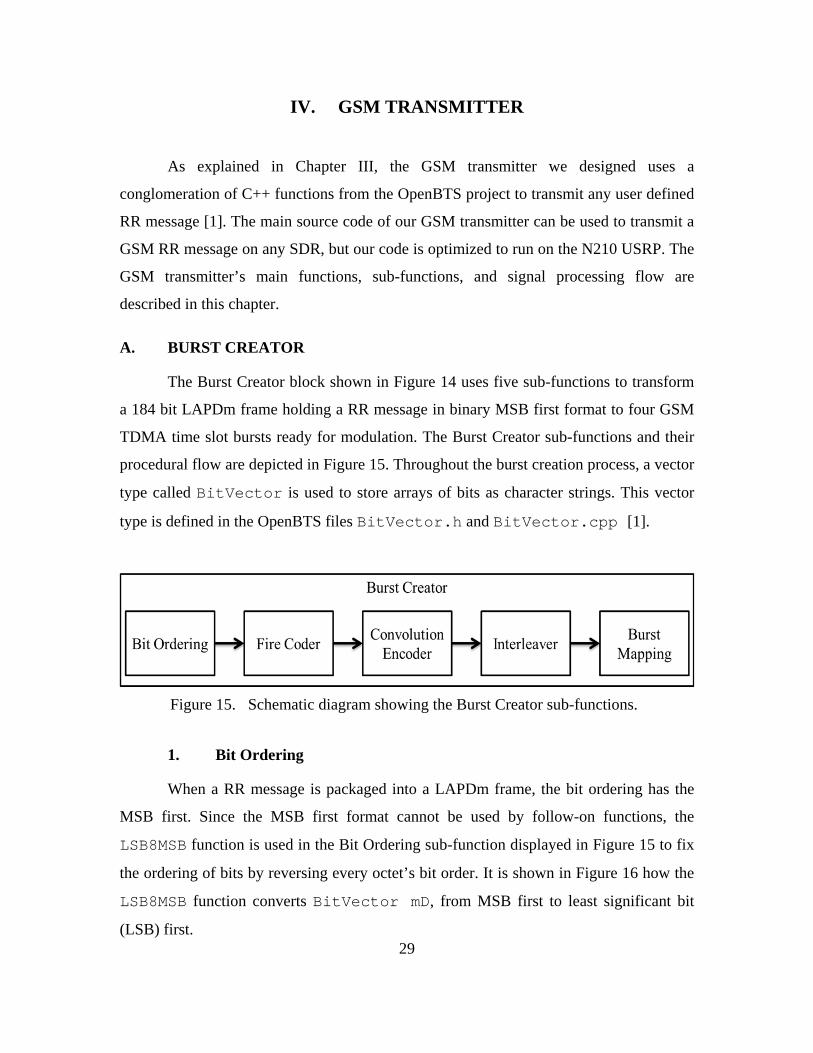
IV. GSM TRANSMITTER ..............................................................................................29 A. BURST CREATOR .......................................................................................29
1. Bit Ordering .......................................................................................29 2. Fire Coder ...........................................................................................30 3. Convolution Encoder .........................................................................32 4. Interleaver ..........................................................................................32 5. Burst Mapping ...................................................................................33
B. BURST MODULATOR ................................................................................34 1. Modulator ...........................................................................................35 2. Burst Scalar ........................................................................................37
viii
3. Table Filler .........................................................................................38 4. Re-sampler ..........................................................................................39
C. BURST TRANSMITTER .............................................................................41 1. USRP Initialization Coding ...............................................................41 2. Transmission Coding .........................................................................42
V. TESTING AND EVALUATION ..............................................................................45 A. BTS TRANSMISSION OF BCH ..................................................................46
1. Code Creation.....................................................................................46 2. Setup ....................................................................................................46
a. ASCOM TEMS GSM Message Collection .............................46 b. Airprobe’s GSM-receiver ........................................................47 c. Experiment Setup ....................................................................48
3. Results .................................................................................................48 a. GNU Radio Collection ............................................................49 b. Signal Analyzer Collection .....................................................49 c. Wireshark Collection ..............................................................51
B. HANDOVER FAILURE MESSAGE TRANSMISSION ...........................53 C. QUEUEING THE HANDOVER FAILURE MESSAGE
TRANSMISSION ...........................................................................................54 1. Code Creation.....................................................................................54
a. Handover Failure Message Creation .....................................54 b. Transmission Queuing Using Packet Capture Library
(PCAP) Code ...........................................................................55 c. Setup ........................................................................................55
2. Results .................................................................................................56 a. Wireshark Collection ..............................................................56 b. GNU Radio Collection ............................................................57 c. Signal Analyzer Collection .....................................................58
3. Timing Issues ......................................................................................59
VI. CONCLUSIONS ........................................................................................................63 A. SIGNIFICANT CONTRIBUTIONS ............................................................64 B. FUTURE WORK ...........................................................................................65
APPENDIX A. XGOLDMON .....................................................................................67
APPENDIX B. BURST CREATOR AND GSM TRANSMITTER C++ CODE REPLICATING BTS .................................................................................................71 A. GSM_MESSAGE_HEXADECIMAL_TO_BINARY.PY ..........................71 B. GSM_BURST_CREATOR.CPP ..................................................................74 C. GSM_BTS_TRANSMITTER.CPP ..............................................................76
APPENDIX C. GSM TRANSMITTER C++ CODE FOR TRIGGERED HANDOVER FAILURE MESSAGE .....................................................................107
LIST OF REFERENCES ....................................................................................................117
INITIAL DISTRIBUTION LIST .......................................................................................119

ix
LIST OF FIGURES
Figure 1. Sequence of operations when a mobile device is conducting a successful handover from GSM to UMTS (after [8], [16] and [17]). .................................7
Figure 2. Sequence of operations when a mobile device fails to hand over from GSM to UMTS (after [8]). .................................................................................8
Figure 3. The structured format of a GSM RR handover failure message (after [7]). ......9 Figure 4. The structured format of a GSM LAPDm type B frame used to send GSM
RR messages (after [13]). ..................................................................................9 Figure 5. A graphical depiction of all five GSM TDMA time slot burst formats
(after [19]). .......................................................................................................10 Figure 6. A diagram of the mapping process from logical GSM channels to physical
GSM channels (after [20]). ..............................................................................12 Figure 7. Mapping scheme for the 51 frame long BCH and CCCH onto physical
time slot zero (after [20]). ................................................................................14 Figure 8. A diagram showing the mapping scheme for the 102 frame long SDCCH/8
onto physical time slot one (after [20]). ...........................................................14 Figure 9. A depiction of the downlink and uplink time slot spacing between the
SDCCH/8 channels (after [20]). ......................................................................15 Figure 10. The block diagram for the GSM fire coder process used for RR messages
(after [12]). .......................................................................................................17 Figure 11. The graphic depiction of the shift register model for the GSM ½-rate
convolutional encoder (after [12]). ..................................................................18 Figure 12. A diagram of the interleaving and burst mapping process used on
messages transmitted on the SDCCH or BCCH (after [12]). ..........................20 Figure 13. Diagram of the exploitation of a potential vulnerability initiated during the
handover to UTRAN process. ..........................................................................25 Figure 14. Schematic diagram detailing the process flow within the GSM transmitter. ..26 Figure 15. Schematic diagram showing the Burst Creator sub-functions. ........................29 Figure 16. Example of LSB8MSB() function converting the bit ordering from MSB
first to LSB first. ..............................................................................................30 Figure 17. Graphic depiction of how the hexadecimal numbers stored in variable
wCoefficients are equivalent to g(D), the generator polynomial from Equation (1). ....................................................................................................31
Figure 18. Graphical depiction of the parity bit calculator used in the GSM transmitter Fire Coder sub-function. ................................................................31
Figure 19. The shift registers representation of the ½-rate convolutional encoder created by the Convolution Encoder sub-function. ..........................................32
Figure 20. The Interleaver sub-function processing diagram showing the interleaving of bit number 449. ............................................................................................33
Figure 21. Procedure of converting interleaved burst mI[0] to GSM TDMA time slot Burst 0. ......................................................................................................34
Figure 22. Schematic diagram showing the Burst Modulator sub-functions. ...................34

x
Figure 23. Graphical depiction of a synchronization burst converted to a NRZ signal using NRZ Converter task and then rotated using the Burst Rotator task. ......36
Figure 24. Graphical representation of the effects of convolving the in-phase and quadrature phase samples from the Burst Rotator task with a Gaussian pulse. ................................................................................................................37
Figure 25. Graphical illustration of the process of GSM TDMA time slot table filling. ..38 Figure 26. Graphical portrayal of the GSM TDMA time slot burst re-sampling
process conducted by the Re-sampler sub-function block where (a) shows the procedure contained within the Concatenate Burst task, (b) displays the poly-phase filter used in the re-sampling, and (c) illustrates the effect of the Filter Burst task on the concatenated bursts. .........................................40
Figure 27. Block diagram showing the process flow of in-phase and quadrature phase samples though the USRP transmitter (after [23]). ..........................................43
Figure 28. Example capture of ASCOM TEMS message collection equipment capturing (a) the System Information Type 1 RR message, and (b) the message contents of the System Information Type 1 RR message. ................47
Figure 29. Photograph of the experimental setup used for testing the GSM transmitter code sending mimicked GSM BTS messages to Airprobe’s GSM-receiver. ..48
Figure 30. Frequency spectrum plot collected by GNU Radio of the baseband signal created by the GSM transmitter code mimicking the GSM BTS BCH prior to USRP transmission. The blue signal shows the instantaneous frequency spectrum while the green signal is the peak collected signal. ..........................49
Figure 31. A scope plot collected by GNU Radio of the in-phase samples, in blue (Ch 1), and quadrature phase samples, in green (Ch 2), created by the GSM transmitter to mimic a GSM BTS BCH. ..........................................................50
Figure 32. Signal analyzer frequency spectrum collection showing the carrier center frequency of the GSM transmitter’s modulated samples transmitter using the N210 USRP. ...............................................................................................50
Figure 33. A screen capture showing System Information Type 1 RR message with frame number five collected using Airprobe’s GSM-receiver and displayed in Wireshark. ...................................................................................51
Figure 34. A screen capture showing System Information Type 2 RR message with frame number 56 collected using Airprobe’s GSM-receiver and displayed in Wireshark. ....................................................................................................52
Figure 35. A screen capture showing a System Information Type 3 RR message with frame number 107 collected using Airprobe’s GSM-receiver and displayed in Wireshark. ....................................................................................................52
Figure 36. A screen shot of a Wireshark capture showing Airprobe’s GSM-receiver successful collection of a handover failure message where (a) is the captured packet using Airprobe’s GSM-receiver, (b) is the hexadecimal representation of the transmitted handover failure message, and (c) is the type B LAPDm frame structure. ......................................................................53
Figure 37. Photograph of the experimental setup used for testing the modified GSM transmitter code which is programed to trigger the transmission of a
xi
handover failure message based on the reception of a handover to UTRAN message by the Samsung Galaxy S2 phone. ....................................................56
Figure 38. A screen capture showing the Wireshark collection of a Samsung Galaxy S2 phone receiving a handover to UTRAN RR message from its servicing BSC. .................................................................................................................57
Figure 39. Scope plot, collected by GNU Radio, of the in-phase samples, in blue (Ch 1), and the quadrature phase samples, in green (Ch 2), of a modulated handover failure message, created by the GSM transmitter code, prior to USRP transmission. .........................................................................................58
Figure 40. Signal analyzer frequency spectrum collection showing the carrier center frequency of a transmitted handover failure message by our modified GSM transmitter code after being triggered by a Samsung Galaxy S2. ..........58
Figure 41. Stem plot of one-way ping times from the computer to the USRP over an Ethernet cable. ..................................................................................................60
Figure 42. Histogram of elapsed time between receipt of a handover to UTRAN message on the computer’s loopback address from a Samsung Galaxy S2 and the transfer of the first IP packet containing handover failure burst samples to the USRP over an Ethernet cable. ..................................................61
Figure 43. Samsung Galaxy S2 debug information settings tutorial where (a) shows the ServiceMode Main Menu screen, (b) displays the ServiceMode Common screen, and (c) shows the Service Mode Debug Info screen. ..........68
Figure 44. Samsung Galaxy S2 settings tutorial where (a) shows the PhoneUtil screen and (b) displays the SysDump screen. .............................................................69

xii
THIS PAGE INTENTIONALLY LEFT BLANK
xiii
LIST OF TABLES
Table 1. List of logical channels used by a GSM network (from [19]). ........................11 Table 2. Common downlink channel combinations used by a GSM network (from
[19])..................................................................................................................11 Table 3. Rotational direction of a GSM TDMA time slot burst symbol derived from
the previous and current symbols. ...................................................................35 Table 4. USRP variables and their values used during testing of GSM transmitter. .....42

xiv
THIS PAGE INTENTIONALLY LEFT BLANK
xv
LIST OF ACRONYMS AND ABBREVIATIONS
3GPP 3rd Generation Partnership Project
BCCH broadcast control channel
BCH broadcast channel
BSC base station controller
BTS base tranceiver station
CCCH common control channel
FCCH frequency correction channel
GSM global system for mobile communications
LAPDm link access procedure on Dm channel
MSB most significant bit
MSC mobile switching center
NPS Naval Postgraduate School
NRZ non-return to zero
PCAP packet capture library
PCH paging channel
RR radio resource management
SCH synchronization channel
SDCCH stand-alone dedicated control channel
SDR software defined radio
TDMA time-division multiple access
UMTS universal mobile telecommunications system
USRP universal software radio peripheral
UTRAN universal terrestrial radio access network

xvi
THIS PAGE INTENTIONALLY LEFT BLANK

xvii
EXECUTIVE SUMMARY
The increased usage of cell phones for data transmission has led to the deployment and
installation of universal mobile telecommunications system (UMTS) networks co-located
with traditional global system for mobile communications (GSM) networks. When the
UMTS standards were developed, they fixed a number of security flaws embedded in the
GSM standards but maintained the interoperability between the two standards. This
interoperability of standards exposed both networks to vulnerabilities exploitable by
malicious actors.
In this thesis, we (i) propose a potential vulnerability caused by the
interoperability of the GSM/UMTS standards, (ii) develop the structure needed to create
a device for testing GSM/UMTS network vulnerabilities, and (iii) provide the code for a
software defined radio (SDR) GSM transmitter. The vulnerability proposed in this thesis
prevents mobile devices from handing over from the GSM network to the UMTS
network by exploiting the GSM network message authentication procedures and the
weakness of the encryption algorithms used by the stand-alone dedicated control channel
(SDDCH). The testing of the vulnerability requires the creatation of a device capable of
transmitting and receiving GSM messages in accordance with the 3rd Generation
Partnership Project (3GPP) GSM standards.
Specifically, we need the testing device to collect the radio resource management
(RR) message sent from the GSM network to the mobile device instructing the mobile
device to hand over to the UMTS network, and we need the device to transmit the RR
handover failure message during a pre-determined time slot. Ideally, we would use cell
phones to act as our GSM/UMTS network vulnerability testing device, but their
manufacturers prevent the consumer from altering device firmware, making them
unconfigurable. The proprietary nature of the mobile device industry has, therefore,
necessitated the use of an SDR as our configurable GSM transmit and receive device in
this thesis. An SDR provides us the ability to create any GSM message, package those
messages into frames, encode the frames into bursts, and modulate the bursts in
accordance with the 3GPP GSM standards using only software we construct.
xviii
GSM transmission and reception using an SDR is well established but poorly
documented. The OpenBTS project is an open source software package, which when
coupled with an SDR provides GSM service to commercial cell phones [1]. The
OpenBTS project, however, prevents users from transmitting any desired message,
making it inadequate for vulnerability testing. Therefore, in this thesis, we reverse
engineered and modified the OpenBTS code in order to create a GSM transmitter capable
of transmitting any GSM RR message.
The GSM transmitter we created in C++ code takes a link access procedure on
Dm channel (LAPDm) frame containing a RR message from data bits to modulated in-
phase and quadrature phase samples ready for transmission by a N210 universal software
radio peripheral (USRP). The C++ code we developed first block encodes the LAPDm
frame data bits, then passes the encoded bits through a ½-rate convolutional encoder,
interleaves the convolved bits and maps the bits to a normal burst. Once formed into a
normal burst, the code we developed diffentially encodes the burst, converts the burst bits
to ( ) symbols, convolves the symbols using a Gaussian pulse, resamples the in-phase
and quadrature phase samples in order to transmit the burst at the N210 USRP sampling
rate and type converts the samples from C++ type float to type short in preparation for
sending the samples to the N210 USRP.
After confirming the GSM transmitter was capable of transmitting a GSM RR
message in accordance with the 3GPP GSM standards by collecting the sent RR
messages using Airprobe’s GSM-receiver software, we developed and demonstrated a
method for testing the forementioned GSM/UMTS interoperability vulnerability. The
method involved collecting a handover to UTRAN message using a Samsung Galaxy S2
phone coupled with xgoldmon code that triggers the GSM transmitter to send a GSM
handover failure message. Packet capture library (PCAP) functions were added to
faciliate the GSM transmitter code to listen to the computer’s loopback address and
trigger the transmission of a handover failure message.
Since our proposed testing method was unsuccessful at inserting the handover
failure message into the correct time slots on the base transceiver station, we explored the
code’s timing issues. We collected multiple runs of the GSM transmitter code triggered
xix
by a handover to UTRAN message and found an inconsistency in the code runtime, which
confirmed the need for a timing function that synchronizes the receiver and transmitter
processes. Also, we found the maximum transmission time for samples from the GSM
transmitter to reach the N210 USRP, which must be taken into account to ensure the
samples are transmitted by the N210 USRP at the correct time.
LIST OF REFERENCES
[1] D. Burgess, H. Samra, R. Sevlian, A. Levy, and P. Thompson. (2013). OpenBTS
Public Release [Online software]. Available: http://wush.net/svn/range/software/public

xx
THIS PAGE INTENTIONALLY LEFT BLANK

xxi
ACKNOWLEDGMENTS
Dr. Tummala and Dr. McEachen, thank you for your expertise and direction
throughout this thesis research process. Your guidance encouraged and challenged me to
test my intellectual limits.
Bob Broadston, Donna Miller, and Phil Hopfner, thank you for all the support and
extra work required in assisting me in acquiring testing equipment and troubleshooting
software.
Jesus Rodriquez, thank you for your assistance in setting up the cell phone
network on the Naval Postgraduate campus and ensuring its full functionality throughout
my research process.

xxii
THIS PAGE INTENTIONALLY LEFT BLANK
1
I. INTRODUCTION
The increased usage of cell phones for data transmission has led to the
deployment and installation of universal mobile telecommunications system (UMTS)
networks co-located with traditional global system for mobile communications (GSM)
networks. When the UMTS standards were developed, they fixed a number of security
flaws embedded in the GSM standards but maintained the interoperability between the
two standards. This interoperability of standards opened the flood gates for possible
malicious attacks. The testing of such vulnerabilities requires the creation of a
configurable device capable of both sending and receiving any GSM message.
Currently, cell phones are relatively cheap, making them a potentially perfect
choice for a GSM vulnerability testing device, but their manufacturers prevent the
consumer from altering device firmware, making them unconfigurable. The proprietary
nature of the mobile device industry has, therefore, necessitated the use of a software
defined radio (SDR) as our configurable GSM transmit and receive device.
A SDR provides us the ability to create any GSM message, package those
messages into frames, encode the frames into bursts, and modulate the bursts in
accordance with the 3rd Generation Partnership Project (3GPP) GSM standards because
all the processes are coded in software we construct. The only non-configurable portion
of the SDR is its hardware that transforms the modulated digital samples, created in
software, to a transmitted analog waveform at any desired carrier frequency.
A. THESIS OBJECTIVE
In this thesis, we propose and investigate a potential vulnerability caused by the
interoperability of the GSM and UMTS standards, which when exploited prevents mobile
devices from handing over from the GSM network to the UMTS network. This potential
vulnerability hinges on the weakness of the encryption algorithms employed by the GSM
standards and the ability to create a device capable of transmitting and receiving GSM
messages in accordance with the 3GPP GSM standards.
2
The testing of the proposed vulnerability requires the creation of a device capable
of collecting and transmitting GSM radio resource management (RR) messages.
Specifically, we need the device to collect the RR message sent from the GSM network
to the mobile device instructing the mobile device to hand over to the UMTS network,
and we need the device to transmit the RR handover failure message during a pre-
determined time slot.
Since configurable devices capable of GSM RR message collection already exist,
the objective of this thesis is to develop an open source GSM transmitter using an SDR to
encode and transmit any RR message in accordance with the 3GPP GSM standards. In
addition to creating a GSM transmitter, we also propose an integration technique that
combines our GSM transmitter with a GSM receiver, resulting in a triggered GSM
transmitter capable of automatically sending a GSM message after reception of a pre-
determined GSM message from a base station controller (BSC).
B. RELATED WORK
GSM transmission and reception using an SDR is well established but poorly
documented. The OpenBTS project is an open source software package which, when
coupled with a SDR, provides GSM service to commercial cell phones [1]. The
OpenBTS project, however, prevents users from transmitting any desired message, thus
making it inadequate for vulnerability testing. The Airprobe [2] project, another open
source software project, uses GNU Radio [3] and an SDR to collect the base transceiver
station (BTS) downlink channel but, unfortunately, lacks the capability to transmit GSM
messages. In this thesis, we reverse engineer the OpenBTS code and re-package the code
to create a GSM transmitter capable of triggered transmission of any GSM RR message.
In addition to research involving the use of an SDR to transmit and receive GSM
messages, Southern [4] and Meyer [5] have examined the security impacts of
interoperating GSM and UMTS networks. Specifically, their works examined the
weakness of the GSM encryption algorithms discussed by Ekdahl [6] on GSM/UMTS
heterogeneous networks. In this thesis, we uncover a potential undocumented
3
vulnerability caused by interoperating GSM and UMTS networks coupled with the weak
GSM encryption algorithms discussed in [6].
The 3GPP GSM standards [7]-[13] provide the technical specifications for
transforming the GSM message bits into a modulated burst. The C++ computer code
developed in this thesis for transforming the RR message bits into a modulated burst
specifically follows the 3GPP GSM standards.
C. ORGANIZATION
The aspects of the 3GPP standards that are pertinent to the development of the
GSM transmitter are outlined in Chapter II. The topics covered include known GSM
vulnerabilities, GSM to universal terrestrial radio access network (UTRAN) handover
procedures, GSM physical and logical channel structure, and the GSM burst transmission
processing from message creation to burst modulation.
The possible vulnerability of allowing handovers from the GSM network to the
UMTS network is explored in Chapter III, and a generic solution is developed for the
design of a device capable of testing the described vulnerability. Finally, a detailed
process diagram is presented containing all the functions and sub-functions needed to
create a GSM transmitter capable of RR message generation and transmission using the
Ettus N210 universal software radio peripheral (USRP).
The thorough desciption of how the GSM transmitter computer code we
developed transitions an RR message from a binary bit string into a GSM burst ready for
transmission by the N210 USRP is provided in Chapter IV. It begins with the
transformation of the data bits into GSM bursts, continues with the re-sampling and burst
scaling, and concludes with burst transmission using the N210 USRP.
The validation of the GSM transmitter’s capability to transmit an RR message is
demonstrated in Chapter V. Initially, the need for the GSM transmitter to mimic a GSM
BTS in order to confirm encoding and modulation techniques is discussed. Then testing
of the GSM handover failure RR message transmission is presented and results
4
explained. Next, the GSM transmitter queuing process is described and tested. Finally,
timing issues caused by using an SDR as a GSM burst transmitter are analyzed.
Additional information about the xgoldmon software used in Chapter V is
contained in Appendix A, the C++ code developed for the GSM transmitter mimicking a
GSM BTS is listed in Appendix B, and the C++ code used for the queued transmission of
a handover failure message is displayed in Appendix C.
5
II. GSM VULNERABILITIES AND FUNDAMENTALS
Heterogeneous networks composed of both GSM and UMTS networks continue
to increase rapidly as UMTS capable phones become the norm. Even though many of the
GSM vulnerabilities were fixed in the roll out of the UMTS networks, the backward
compatibility continues to allow malicious users to exploit unwitting cell phone users. A
brief overview of the current GSM vulnerabilities, the solutions incorporated in the
UMTS networks to fix the GSM security flaws, and a description of the GSM signal
messaging process from message generation through burst modulation are provided in the
following sections.
A. GSM VULNERABILTIES
Since the creation of GSM networks, researchers have been diligently working to
identify and correct any discovered vulnerabilities. Many of the current vulnerabilities
stem from the one-way authentication employed by a GSM phone and the weakness of
the encryption algorithms used for secure communication between GSM towers and
GSM phones.
1. Rogue Base Station
The vulnerability of one-way authentication between a GSM phone and the
servicing GSM network is often referred to as the rogue base station vulnerability. The
GSM standards only require the mobile device to authenticate itself to the GSM network
but not for the network to authenticate itself to the phone. Since the phone never
authenticates the servicing network, the phone is left vulnerable to malicious actors
creating fake base stations and luring unsuspecting users to attach to their network. Once
a user is attached, the malicious actor can capture the mobile device’s international
mobile subscriber identity (IMSI) and even force the mobile device not to use encryption
[5], [14].
6
2. Weak A5/1 and A5/2 Encryption
When the GSM standards were first introduced, the encryption algorithms, A5/1
and A5/2, used for securing message signaling and protecting active call content were
kept secret from the public. This idea of security through obscurity backfired because in
1994 the A5/1 encryption algorithm was leaked to the public, and by 1999 both
algorithms had been reverse engineered by Briceno, Goldberg and Wagner [15]. Since
the discovery of the A5/1 and A5/2 encryption algorithm designs, myriad individuals
have created techniques for breaking the encryption to include an ability to crack the
algorithms in real time [4], [6].
3. Solution in UMTS Networks
Since the forementioned vulnerabilities exist in the GSM standards, when the
UMTS network standards were created, the developers changed the authentication
process and encryption algorithms. The UMTS standards require both the network and
phone to authenticate one another, which fixed the rogue base station vulnerability
prevalent in the GSM standards. Additionally, the UMTS standards changed the
encryption algorithm to use the block coder, KASUMI, and made the encrypting process
open source, which allowed the public to ensure the security of the algorithm [4].
B. HANDOVER TO UTRAN
Before we explore potential vulnerabilities associated with mixing GSM and
UMTS networks, we must first understand how they were designed to interoperate. The
handover to UTRAN procedure allows a mobile device to hand over from a GSM
network to a UMTS network. This process is accomplished through the sending and
receiving of RR messages between the GSM BTS and mobile device on the logical stand-
alone dedicated control channel (SDCCH) [8].
1. Handover to UTRAN Messaging
The successful execution of a handover from the GSM network to the UMTS
network involves a seven step process derived from [8], [16] and [17] and shown in
Figure 1. First the GSM network sends the Inter System to UTRAN handover command
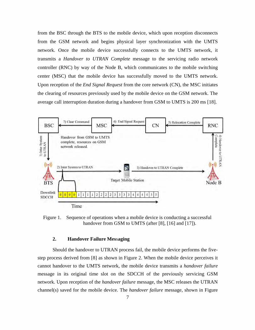
7
from the BSC through the BTS to the mobile device, which upon reception disconnects
from the GSM network and begins physical layer synchronization with the UMTS
network. Once the mobile device successfully connects to the UMTS network, it
transmits a Handover to UTRAN Complete message to the servicing radio network
controller (RNC) by way of the Node B, which communicates to the mobile switching
center (MSC) that the mobile device has successfully moved to the UMTS network.
Upon reception of the End Signal Request from the core network (CN), the MSC initiates
the clearing of resources previously used by the mobile device on the GSM network. The
average call interruption duration during a handover from GSM to UMTS is 200 ms [18].
Figure 1. Sequence of operations when a mobile device is conducting a successful handover from GSM to UMTS (after [8], [16] and [17]).
2. Handover Failure Messaging
Should the handover to UTRAN process fail, the mobile device performs the five-
step process derived from [8] as shown in Figure 2. When the mobile device perceives it
cannot handover to the UMTS network, the mobile device transmits a handover failure
message in its original time slot on the SDCCH of the previously servicing GSM
network. Upon reception of the handover failure message, the MSC releases the UTRAN
channel(s) saved for the mobile device. The handover failure message, shown in Figure

8
3, is a layer three RR message packaged into a type B link access procedure on Dm
channel (LAPDm) frame [7], [13]. The LAPDm type B frame contains a three-octet
header with fields containing the link protocol discriminator (LPD), the service access
point identifier (SAPI), the command/response (C/R), a transmitter-receive sequence
number N(R), a transmitter-send sequence number N(S), a more bit (M), and a length
indicator extension bit (EL). The structured format of the LAPDm type B frame and how
a layer three RR message is packaged within the frame is shown in Figure 4.
Figure 2. Sequence of operations when a mobile device fails to hand over from GSM to UMTS (after [8]).
The values within the handover failure message are relatively constant. The skip
indicator is always set to hexadecimal value 0, and the protocol discriminator value,
which defines the layer three message type, is always set to hexadecimal value 6 for RR
messages. The message type field identifies the type of RR message. All possible RR
messages are listed in Table 9.1.1 of [7]. The hexadecimal value 40 indicates that the
message is a handover failure RR message. The final field, RR cause, allows the mobile

9
device to inform the GSM network of the cause for the failed handover. A list of all
possible RR cause information elements is located in Table 10.5.2.31.1 of [7].
Figure 3. The structured format of a GSM RR handover failure message (after [7]).
Figure 4. The structured format of a GSM LAPDm type B frame used to send GSM RR messages (after [13]).
C. GSM PHYSICAL AND LOGICAL CHANNELS
The GSM standard defines logical channels as either traffic channels (TCH) or
signaling channels transmitted in designated time slots on the physical channel. The
physical channel uses a combination of frequency and time-division multiplexing to
create time slots filled with one of the burst types shown in Figure 5. These time slots are
then modulated and transmitted over the air interface from the BTS to the mobile device
on the downlink channel or in the opposite direction for the uplink channel. The

10
bandwidth allotted to either the uplink channel or downlink channel is 200 kHz. The
uplink and downlink channel center frequencies are separated by 45 MHz, and a time slot
on either channel has a period of 576.9 µs. Since the GSM sample rate is 270.833 kHz,
the number of bits per time slot is 156.25, and the bit period is 3.69 µs. Eight time slots,
labeled zero through seven, are combined to form a time-division multiple access
(TDMA) frame [19].
Figure 5. A graphical depiction of all five GSM TDMA time slot burst formats (after [19]).
The list of logical channels used by the GSM network is shown in Table 1. The
list of a few combinations of logical channels mapped to time slots on the physical
channel and ultimately transmitted on the downlink channel is shown in Table 2. In this
thesis, we focus on the physical time slot zero downlink combination and the SDCCH
time slot combination.
11
Table 1. List of logical channels used by a GSM network (from [19]).
Group Channel Name Direction
Traffic Channel (TCH)
TCH Full-rate TCH (TCH/F)
Half-rate TCH (TCH/H)
Signaling Channels
Broadcast Channel (BCH)
Broadcast Control Channel (BCCH)
Frequency Correction Channel (FCCH)
Synchronization Channel (SCH)
Common Control Channel (CCCH)
Random Access Channel (RACH)
Access Grant Channel (AGCH)
Paging Channel (PCH)
Notification Channel (NCH)
Dedicated Control Channel (DCCH)
Stand-alone Dedicated Control Channel (SDCCH)
Slow Associated Control Channel (SACCH)
Fast Associated Control Channel (FACCH)
Table 2. Common downlink channel combinations used by a GSM network (from [19]).
Physical Time Slots on BTS Carrier Frequency
Downlink Channels
1–7 1 TCH/F + SACH 1–7 2 TCH/H + SACCH 1–7 8 SDCCH + SACCH
0 1 FCCH + 1 SCH + 1 BCCH + 1 AGCH + 1 PCH
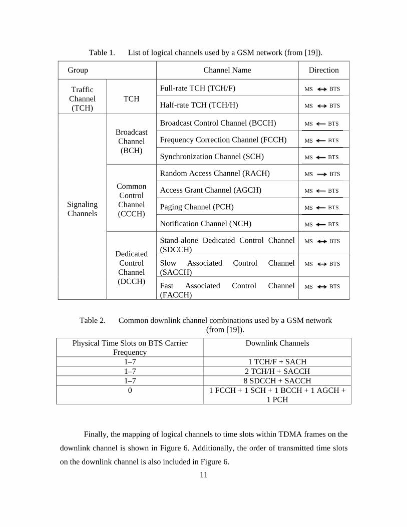
Finally, the mapping of logical channels to time slots within TDMA frames on the
downlink channel is shown in Figure 6. Additionally, the order of transmitted time slots
on the downlink channel is also included in Figure 6.
12
Figure 6. A diagram of the mapping process from logical GSM channels to physical GSM channels (after [20]).
1. Broadcast Channel (BCH) and Common Control Channel (CCCH)
The BCH is used by the GSM network to communicate the network
characteristics to the mobile device. It also aids in the time and frequency
synchronization of the mobile device with the GSM network. The BCH is transmitted
during time slot zero of the BTS and has a frame structure length of 51 TDMA frames as
shown in Figure 7. Each TDMA frame time slot contains one of the five different bursts
previously described and displayed in Figure 5. The first burst transmitted in frame zero
of the BCH is the frequency correction burst, which is one time slot long and contains
142 consecutive zero bits. When the frequency correction burst is modulated, it resembles
a sine wave 67.7 kHz above the center frequency, which allows the mobile device to tune
in frequency with the BTS [20].
The next transmitted burst is the synchronization burst, which is also one time slot
in length but contains the BTS identity code (BSIC), the reduced TDMA frame number
(RFN) and a 64 bit long training sequence instead of the normal 26 bit long training
sequence used in the normal burst [11]. The synchronization burst allows the mobile
device to synchronize in time with the BTS because of the extra-long training sequence
and the transmission of the current frame number [20].
13
The broadcast control channel (BCCH) uses the normal burst structure for
transmitting the RR system information type messages. These system information type
messages sent on the BCCH help to inform the mobile devices of the GSM network’s
settings. The other type of burst shown in Figure 7 titled CCCH are made up of the
paging channel (PCH) and the access grant channel (AGCH) messages sent from the
network to the mobile device using the normal burst structure. Finally, the idle time slot
is filled with a predefined 142 bit long sequence called a dummy burst. Since the BTS
must transmit during every time slot, it transmits dummy bursts anytime it does not have
any other burst to send [20].
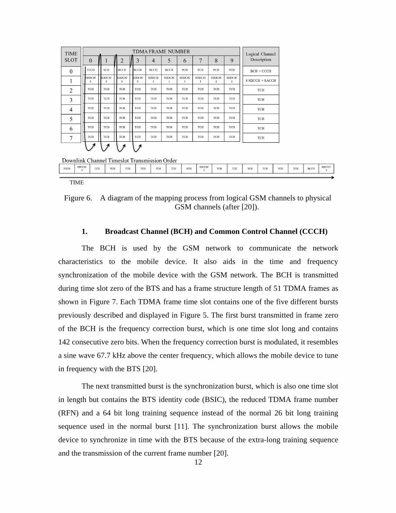
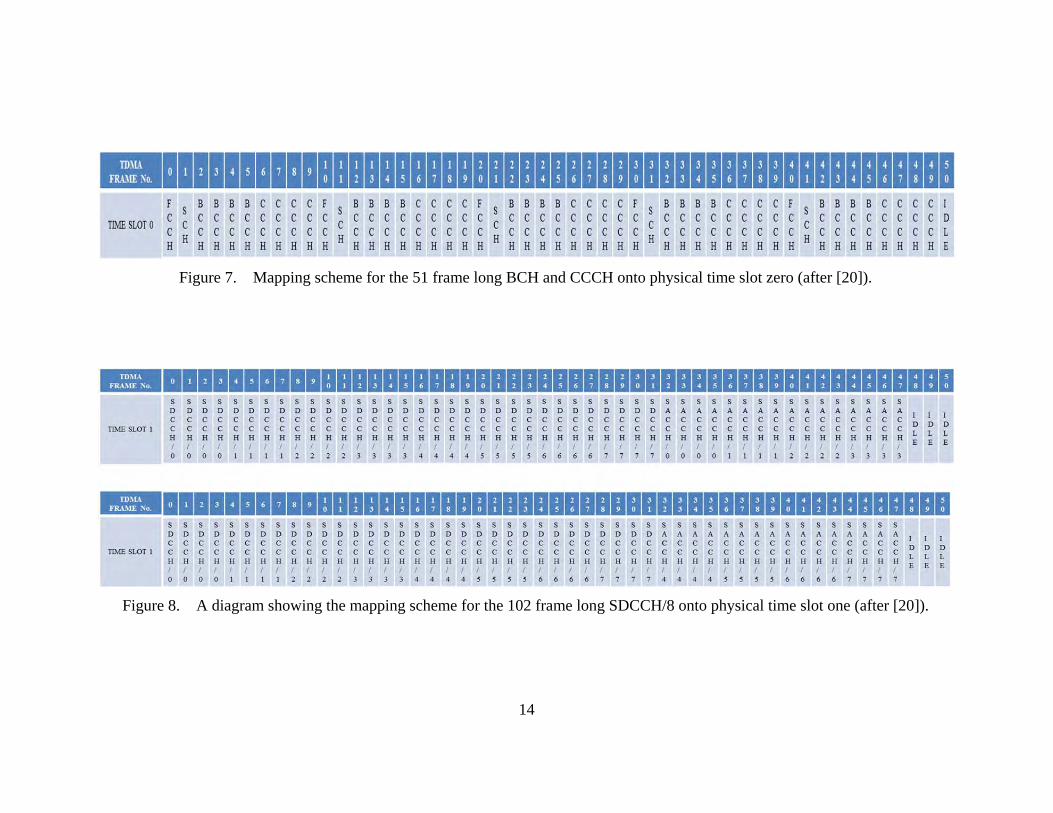
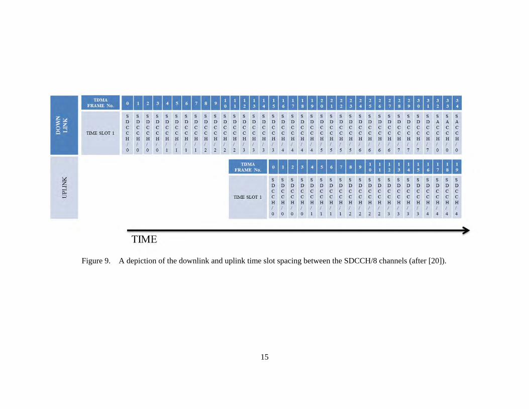
2. Stand-Alone Dedicated Control Channel (SDCCH)
The SDCCH is the logical channel responsible for RR messaging between the
network and mobile device. The SDCCH is usually transmitted in time slot one of the
uplink and downlink GSM TDMA physical channel. The frame structure used on the
SDCCH contains 102 TDMA frames as shown in Figure 8. The channel operates by
assigning a mobile device to a numbered time slot from zero to seven. During the mobile
device’s time slot on the downlink channel, the mobile device listens for any messages
sent to it by the BTS. The uplink channel operates identically to the downlink channel
except the mobile device transmits its RR messages, and the TDMA frames are shifted in
time by 15 time slots as shown in Figure 9 [20]. The time difference between the last bit
of the time slot burst being sent to the mobile device on the downlink SDCCH and the
first bit transmitted by the mobile device on the uplink channel is 55.0323 ms.
D. GSM MESSAGING
GSM messaging allows the network and mobile device to discover each other and
setup and teardown phone calls, along with myriad other functions resulting in the mobile
device successfully communicating on the GSM network.
14
Figure 7. Mapping scheme for the 51 frame long BCH and CCCH onto physical time slot zero (after [20]).
Figure 8. A diagram showing the mapping scheme for the 102 frame long SDCCH/8 onto physical time slot one (after [20]).
15
Figure 9. A depiction of the downlink and uplink time slot spacing between the SDCCH/8 channels (after [20]).

16
1. GSM Layer Three Messaging
The GSM layer three signaling protocol consists of three sub-layers: radio
resource management (RR), mobility management (MM), and connection management
(CM). The RR messaging controls the handovers initiated by the GSM network through
the sending of messages over the SDCCH to the mobile device. These are the critical
messages for this thesis because we need to construct the RR handover failure message,
as shown in Figure 3, in order to test a possible vulnerability present in heterogeneous
GSM/UMTS networks. The layer three RR messages are packaged within a layer two
frame, called a LAPDm frame, prior to encoding and modulation [19].
2. GSM Layer Two Messaging
The GSM layer two messaging protocol is achieved through the use of the
LAPDm protocol, which provides successful transfer of signaling information between
the GSM network and the mobile device over the air interface. When the RR message is
packaged into a layer two frame, as shown in Figure 4, a three-octet layer two header is
used to communicate the address, type, and length of the frame. This information helps to
reassemble layer three messages and pass them to the correct service access point (SAP)
for further processing. Since the LAPDm frame is a constant 184 bits in length, fill bits
are used to ensure that the LAPDm frame is full prior to burst forming. The fill bits used
for empty octets have hexadecimal value 2B [13], [19].
E. GSM BURST FORMING
After the creation, formatting, and packaging of the GSM data message into a
LAPDm frame, it needs to be formed into a GSM TDMA time slot burst. The burst
forming process includes block coding, convolution encoding, interleaving, and burst
mapping.
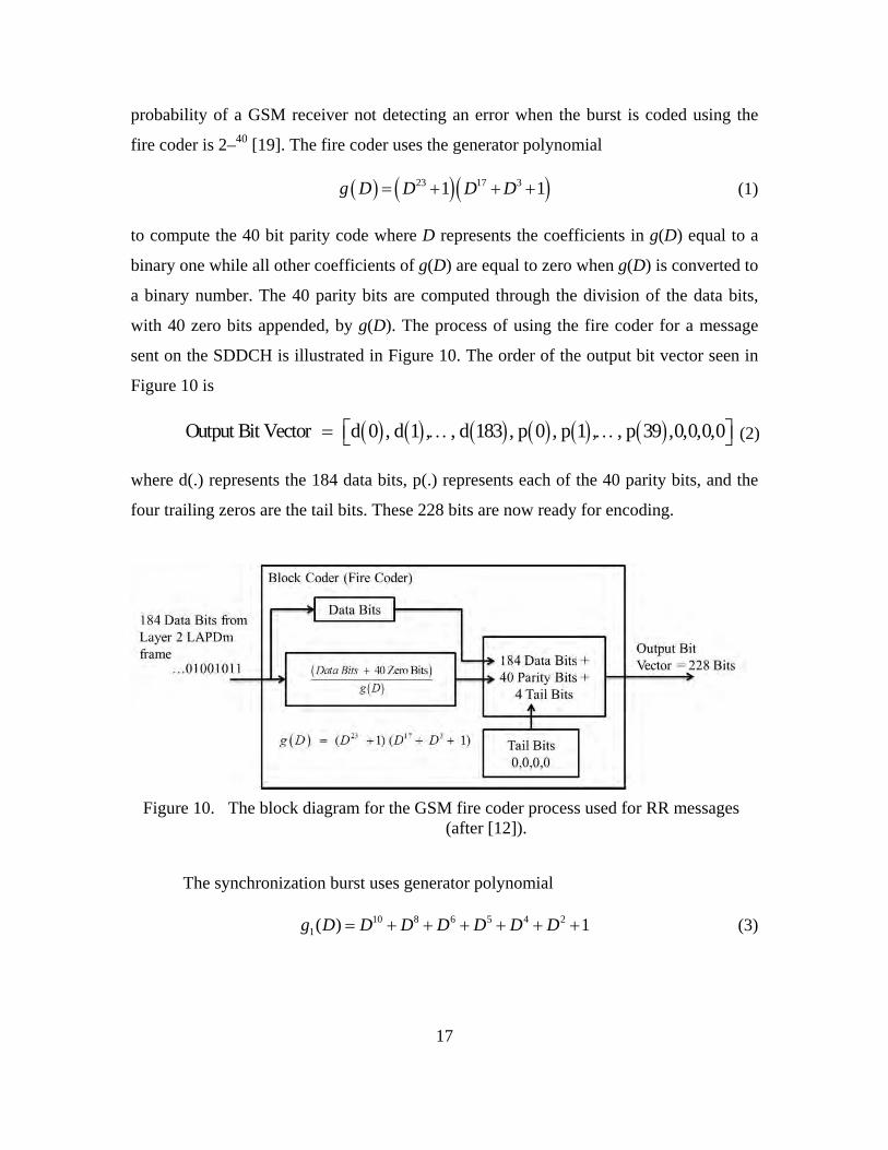
1. Block Coder
The 3GPP GSM standard [12] uses a block coder called a fire coder to detect bit
errors in the GSM TDMA time slot bursts transmitted on the SDCCH and BCCH. The
17
probability of a GSM receiver not detecting an error when the burst is coded using the
fire coder is 2–40 [19]. The fire coder uses the generator polynomial
23 17 31 1g D DD D (1)
to compute the 40 bit parity code where D represents the coefficients in g(D) equal to a
binary one while all other coefficients of g(D) are equal to zero when g(D) is converted to
a binary number. The 40 parity bits are computed through the division of the data bits,
with 40 zero bits appended, by g(D). The process of using the fire coder for a message
sent on the SDDCH is illustrated in Figure 10. The order of the output bit vector seen in
Figure 10 is
Output Bit Vector d 0 , d 1 , , d 183 , p 0 , p 1 , , p 39 , 0, 0, 0, 0 (2)
where d(.) represents the 184 data bits, p(.) represents each of the 40 parity bits, and the
four trailing zeros are the tail bits. These 228 bits are now ready for encoding.
Figure 10. The block diagram for the GSM fire coder process used for RR messages (after [12]).
The synchronization burst uses generator polynomial
10 8 6 5 4 21( ) 1g D D D D D D D (3)
18
for its block coder instead of ( )g D . Otherwise, the process for computing the
synchronization burst parity bits resembles the procedure shown in Figure 10 except only
25 input data bits enter the block coder and only 10 parity code bits are generated.
2. ½-Rate Convolution Encoder
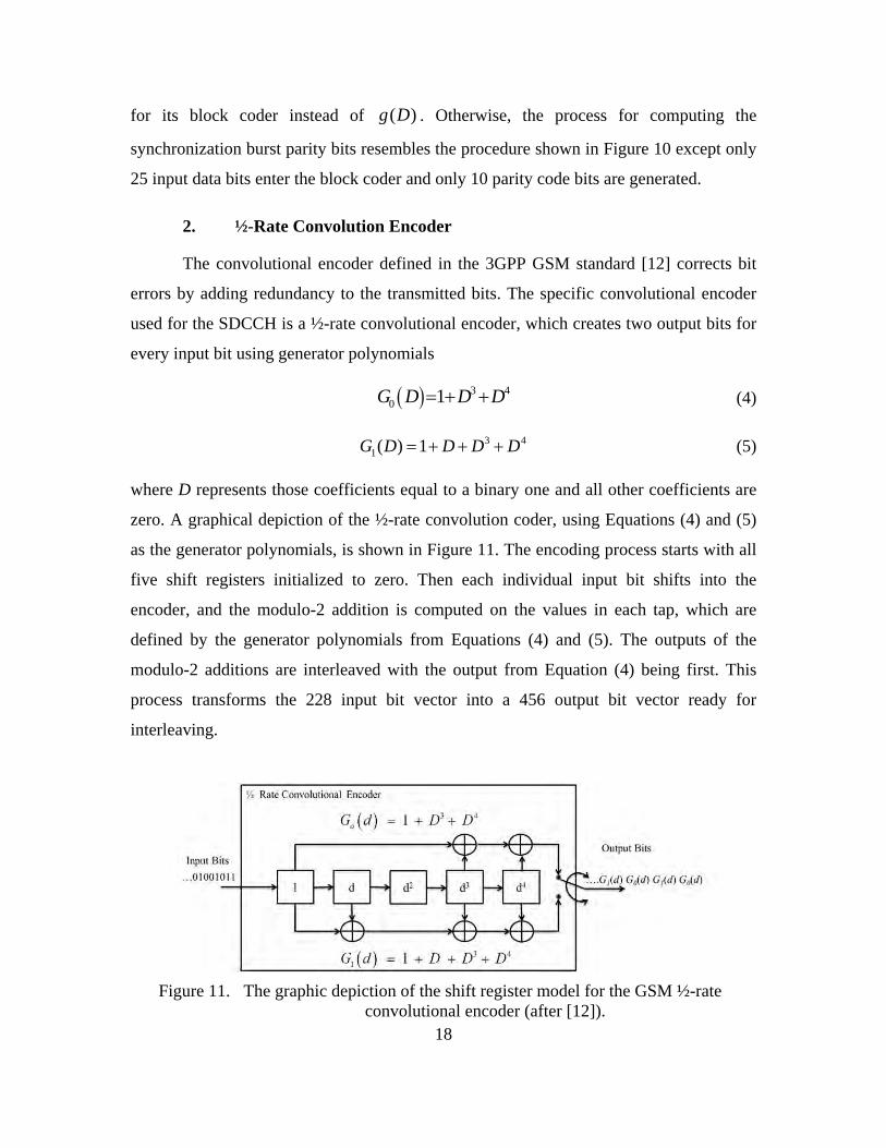
The convolutional encoder defined in the 3GPP GSM standard [12] corrects bit
errors by adding redundancy to the transmitted bits. The specific convolutional encoder
used for the SDCCH is a ½-rate convolutional encoder, which creates two output bits for
every input bit using generator polynomials
3 40 1 G D DD (4)
3 41( ) 1G D D D D (5)
where D represents those coefficients equal to a binary one and all other coefficients are
zero. A graphical depiction of the ½-rate convolution coder, using Equations (4) and (5)
as the generator polynomials, is shown in Figure 11. The encoding process starts with all
five shift registers initialized to zero. Then each individual input bit shifts into the
encoder, and the modulo-2 addition is computed on the values in each tap, which are
defined by the generator polynomials from Equations (4) and (5). The outputs of the
modulo-2 additions are interleaved with the output from Equation (4) being first. This
process transforms the 228 input bit vector into a 456 output bit vector ready for
interleaving.
Figure 11. The graphic depiction of the shift register model for the GSM ½-rate convolutional encoder (after [12]).
19
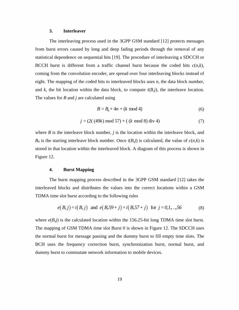
3. Interleaver
The interleaving process used in the 3GPP GSM standard [12] protects messages
from burst errors caused by long and deep fading periods through the removal of any
statistical dependence on sequential bits [19]. The procedure of interleaving a SDCCH or
BCCH burst is different from a traffic channel burst because the coded bits c(n,k),
coming from the convolution encoder, are spread over four interleaving blocks instead of
eight. The mapping of the coded bits to interleaved blocks uses n, the data block number,
and k, the bit location within the data block, to compute i(B,j), the interleave location.
The values for B and j are calculated using
= + 4 + ( mod 4)0B B n k (6)
= (2( (49 ) mod 57) + ( ( mod 8) div 4)j k k (7)
where B is the interleave block number, j is the location within the interleave block, and
B0 is the starting interleave block number. Once i(B,j) is calculated, the value of c(n,k) is
stored in that location within the interleaved block. A diagram of this process is shown in
Figure 12.
4. Burst Mapping
The burst mapping process described in the 3GPP GSM standard [12] takes the
interleaved blocks and distributes the values into the correct locations within a GSM
TDMA time slot burst according to the following rules
and for e B, j = i B, j e B,59+ j = i B,57+ j j =0,1,…,56 (8)
where e(B,j) is the calculated location within the 156.25-bit long TDMA time slot burst.
The mapping of GSM TDMA time slot Burst 0 is shown in Figure 12. The SDCCH uses
the normal burst for message passing and the dummy burst to fill empty time slots. The
BCH uses the frequency correction burst, synchronization burst, normal burst, and
dummy burst to commutate network information to mobile devices.

20
Figure 12. A diagram of the interleaving and burst mapping process used on messages transmitted on the SDCCH or BCCH (after [12]).
F. GSM MODULATION
After the creation of each GSM TDMA time slot burst, they are converted to
symbols through differential encoding and modulated using the Gaussian minimum-shift
keying (GMSK) scheme defined in the 3GPP GSM standard [10].
1. Differential Encoder
The differential encoder in the 3GPP GSM standard [10] forces the current
transmitted symbol to be dependent both on itself and the previous symbol and converts
the binary output of the differential encoder to a non-return to zero (NRZ) sequence ( 1
). The differential encoder accomplishes both functions by first encoding as
1ˆ ( 0,1 )i i i id d d d (9)
where denotes modulo-2 addition and id represents the current input data bit. After
the differential encoding, the encoded data bits are converted as
ˆ1 2 ( 1, 1 )i i ia d a (10)

21
resulting in the NRZ sequence ( 1 ).
2. GMSK Modulation
The symbols from the differential encoder are sent through a frequency filter,
which generates the phase ( )t of the modulated signal. This phase is computed as
( ) ( )bt iT
ii
t a g u du
(11)
where g(u) is the impulse response defined as the convolution of h(t), the impulse
response of a low-pass Gaussian filter, with a rectangular step function / brect t T . The
variable is the modulation index, which is 0.5 for a GSM signal for the purpose of
maintaining a maximum phase shift of / 2 between bit periods Tb. The rectangular step
function used to compute g(u) in Equation (11) is
1 for
2
0 for 2
b
b
b b
Tt
Ttrect
T Tt
(12)
and the Gaussian filter h(t) has impulse response
2
2 2exp
2 ln(2)( ) , where = , =0.3
22
bb
bb
t
Th t BT
BTT
(13)
where B represents the 3-dB bandwidth of the filter h(t). Finally, the computed phase
( )t from Equation (11) is input to the phase modulator as follows
0 0
2( ) cos 2 ( ) c
b
Ex t f t t
T (14)
where f0 is the center frequency, Ec is the energy per modulating bit, and 0 is a random
phase component, which remains constant for the duration of an entire GSM TDMA time
22
slot burst. The output of Equation (14) represents the modulated GSM burst sample ready
for transmission at the GSM sample rate of 270.833 kHz.
A brief overview of the current vulnerabilities plaguing GSM networks along
with implemented solutions used on UMTS networks to correct the vulnerabilities were
explained in this chapter. Additionally, the GSM signal messaging for mobile device
handover from GSM to UMTS and handover failure were presented. Finally, GSM
message creation from the layer three messages to burst transmission on a physical
channel was discussed for an unencrypted GSM RR message.
23
III. GSM TRANSMITTER DESIGN FOR VULNERABILITY TESTING
As countries convert their homogeneous GSM networks to heterogeneous
GSM/UMTS networks, vulnerabilities are created in the mixing of the technologies
which must be addressed by the 3GPP standards. As discussed in Chapter II, many of the
GSM vulnerabilities were fixed in the 3GPP UMTS standards; however, the mobile
device must successfully access the UMTS network to take advantage of the
improvements. Therefore, a possible vulnerability not addressed in either the GSM or
UMTS standards is the potential for a malicious entity to prevent a mobile device from
handing over from a GSM to UMTS network because the GSM network maintains the
SDCCH uplink time slots. These time slots are maintained for use in the event a handover
failure occurs, yet their existence allows for potential exploitation due to the weakness in
the encryption algorithms used on the SDCCH to validate the authenticity of sent traffic.
In this thesis, we assume no encryption is used on the network. This is a valid assumption
because, as discussed in Chapter II, a primary vulnerability of GSM is the weakness the
of A5/2 and A5/1 encryption schemes.
A. HANDOVER TO UTRAN VULNERABILITY
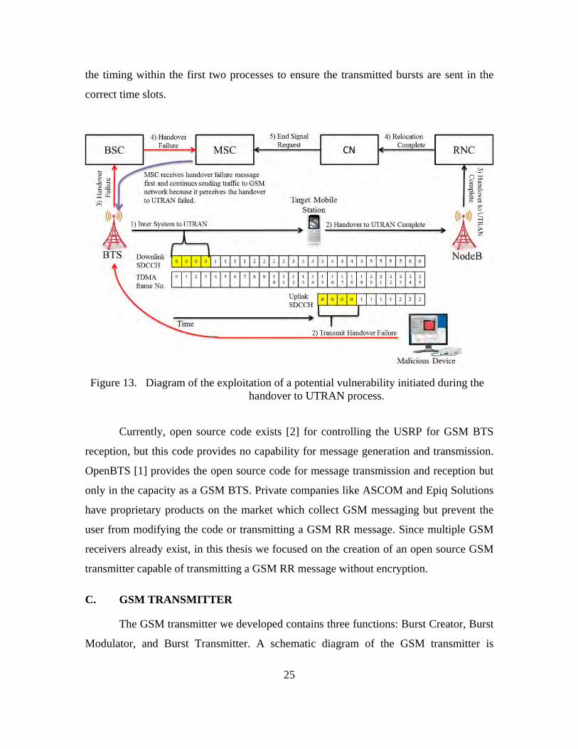
The success and failure handover processes shown in Figure 1 and Figure 2
provide the basis for the hypothesis that vulnerability exists with the current handover to
UTRAN procedures described in Chapter II. During the handover to UTRAN process, the
GSM network continues to keep the mobile station’s four time slots vacant on the
SDCCH uplink channel in the event a handover failure occurs and the mobile station
must return to the original GSM network. The potential vulnerability, shown in Figure
13, results from the GSM network’s continuous collection and processing of any
appropriately formatted messages sent during the time slots of the mobile device coupled
with the network’s sole validation mechanism of sender authenticity being a known
breakable encryption algorithm.
24
As displayed in Figure 13, upon receipt of the layer three RR message initiating a
handover to a designated UMTS network, the mobile device conducts a hard handover
and immediately attempts to establish communications with the new network.
Concurrently, during the attempted handover, a malicious device could transmit a
properly formatted and encrypted handover failure message in the time slots on the
SDCCH uplink channel reserved for the mobile device. If the BSC assumes the handover
failure message was sent from the mobile device, then it should process and transport the
message to the MSC. If the handover failure message reaches the MSC prior to the end
signal request message sent from the UMTS network, which the mobile device initiated
through the sending of a handover complete message to the RNC, then the MSC should
continue to send the mobile device’s traffic to the GSM network instead of the UMTS
network. The reserved UTRAN channel(s) should be released. Since the MSC released
the UTRAN channel(s), the mobile device should cease receiving traffic on the UMTS
network and conclude a handover failure occurred thereby returning to the original GSM
network.
As was explained in Chapter II, the elapsed time between the handover to UTRAN
message being sent by the BTS to the mobile device and the mobile device establishing
communication with the UTRAN Node B is on average 200 ms [18], while the time
frame between the handover to UTRAN message on the downlink SDDCH and the next
available time slot for the mobile device to transmit a handover failure message on the
SDDCH uplink is approximately 54 ms. Therefore, the handover failure message
receives an approximate 146 ms head start over the handover complete message in
reaching the MSC.
B. SYSTEM REQUIREMENTS FOR VULNERABILITY TESTING
The testing of the handover to UTRAN vulnerability requires the creation of three
processes. The first process collects the downlink of the BTS and identifies when a
mobile device receives a handover to UTRAN message. The second process constructs,
encodes, modulates, and transmits a GSM burst signal. Finally, the third process controls
25
the timing within the first two processes to ensure the transmitted bursts are sent in the
correct time slots.
Figure 13. Diagram of the exploitation of a potential vulnerability initiated during the handover to UTRAN process.
Currently, open source code exists [2] for controlling the USRP for GSM BTS
reception, but this code provides no capability for message generation and transmission.
OpenBTS [1] provides the open source code for message transmission and reception but
only in the capacity as a GSM BTS. Private companies like ASCOM and Epiq Solutions
have proprietary products on the market which collect GSM messaging but prevent the
user from modifying the code or transmitting a GSM RR message. Since multiple GSM
receivers already exist, in this thesis we focused on the creation of an open source GSM
transmitter capable of transmitting a GSM RR message without encryption.
C. GSM TRANSMITTER
The GSM transmitter we developed contains three functions: Burst Creator, Burst
Modulator, and Burst Transmitter. A schematic diagram of the GSM transmitter is

26
displayed in Figure 14. The Burst Creator function takes the layer three and layer two
message bits and converts them from binary bits, with the most significant bit (MSB)
first, into four GSM TDMA time slot bursts. The Burst Modulator takes the raw bits from
the GSM TDMA time slot bursts and converts them into in-phase and quadrature phase
samples of C++ type short at the sample rate of 400 kHz. Finally, the Burst Transmitter
converts the in-phase and quadrature phase samples into an analog signal and transmits
the signal at the desired carrier frequency using a N210 USRP. Many of the functions of
the GSM transmitter code were borrowed from the transmission process of the OpenBTS
project code [1]. Currently, no documentation exists on how the OpenBTS code works;
therefore, we reverse engineered the code to identify the correct functions needed to
transmit any desired RR message at any specified time.
Figure 14. Schematic diagram detailing the process flow within the GSM transmitter.
27
In this chapter, a potential vulnerability stemming from the interoperability of
GSM and UMTS networks coupled with weak GSM encryption on the SDCCH was
presented. This potential vulnerability denies mobile devices from successfully
completing a handover from a GSM to a UMTS network. Without the ability to hand
over to the UMTS network, a mobile device must continue to communicate on the GSM
network leaving it vulnerable to the security issues described in Chapter II. The proposed
vulnerability warrants testing, which requires the creation of a device capable of
receiving a handover to UTRAN message and transmitting a handover failure message.
The system requirements for such a device were proposed in this chapter along with the
schematic diagram of an open source GSM transmitter.

28
THIS PAGE INTENTIONALLY LEFT BLANK
29
IV. GSM TRANSMITTER
As explained in Chapter III, the GSM transmitter we designed uses a
conglomeration of C++ functions from the OpenBTS project to transmit any user defined
RR message [1]. The main source code of our GSM transmitter can be used to transmit a
GSM RR message on any SDR, but our code is optimized to run on the N210 USRP. The
GSM transmitter’s main functions, sub-functions, and signal processing flow are
described in this chapter.
A. BURST CREATOR
The Burst Creator block shown in Figure 14 uses five sub-functions to transform
a 184 bit LAPDm frame holding a RR message in binary MSB first format to four GSM
TDMA time slot bursts ready for modulation. The Burst Creator sub-functions and their
procedural flow are depicted in Figure 15. Throughout the burst creation process, a vector
type called BitVector is used to store arrays of bits as character strings. This vector
type is defined in the OpenBTS files BitVector.h and BitVector.cpp [1].
Figure 15. Schematic diagram showing the Burst Creator sub-functions.
1. Bit Ordering
When a RR message is packaged into a LAPDm frame, the bit ordering has the
MSB first. Since the MSB first format cannot be used by follow-on functions, the
LSB8MSB function is used in the Bit Ordering sub-function displayed in Figure 15 to fix
the ordering of bits by reversing every octet’s bit order. It is shown in Figure 16 how the
LSB8MSB function converts BitVector mD, from MSB first to least significant bit
(LSB) first.
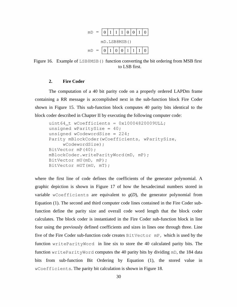
30
Figure 16. Example of LSB8MSB() function converting the bit ordering from MSB first to LSB first.
2. Fire Coder
The computation of a 40 bit parity code on a properly ordered LAPDm frame
containing a RR message is accomplished next in the sub-function block Fire Coder
shown in Figure 15. This sub-function block computes 40 parity bits identical to the
block coder described in Chapter II by executing the following computer code:
uint64_t wCoefficients = 0x10004820009ULL; unsigned wParitySize = 40; unsigned wCodewordSize = 224; Parity mBlockCoder(wCoefficients, wParitySize, wCodewordSize); BitVector mP(40); mBlockCoder.writeParityWord(mD, mP); BitVector mU(mD, mP); BitVector mUT(mU, mT);
where the first line of code defines the coefficients of the generator polynomial. A
graphic depiction is shown in Figure 17 of how the hexadecimal numbers stored in
variable wCoefficients are equivalent to g(D), the generator polynomial from
Equation (1). The second and third computer code lines contained in the Fire Coder sub-
function define the parity size and overall code word length that the block coder
calculates. The block coder is instantiated in the Fire Coder sub-function block in line
four using the previously defined coefficients and sizes in lines one through three. Line
five of the Fire Coder sub-function code creates BitVector mP, which is used by the
function writeParityWord in line six to store the 40 calculated parity bits. The
function writeParityWord computes the 40 parity bits by dividing mD, the 184 data
bits from sub-function Bit Ordering by Equation (1), the stored value in
wCoefficients. The parity bit calculation is shown in Figure 18.
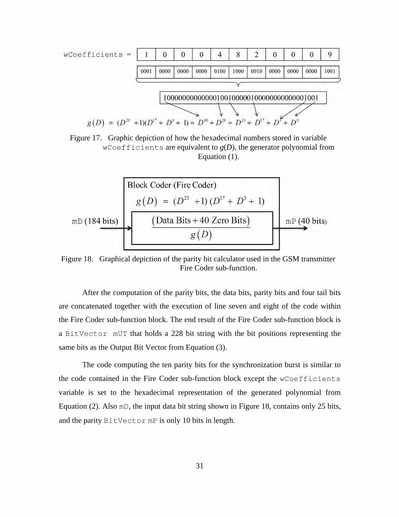
31
Figure 17. Graphic depiction of how the hexadecimal numbers stored in variable wCoefficients are equivalent to g(D), the generator polynomial from
Equation (1).
Figure 18. Graphical depiction of the parity bit calculator used in the GSM transmitter Fire Coder sub-function.
After the computation of the parity bits, the data bits, parity bits and four tail bits
are concatenated together with the execution of line seven and eight of the code within
the Fire Coder sub-function block. The end result of the Fire Coder sub-function block is
a BitVector mUT that holds a 228 bit string with the bit positions representing the
same bits as the Output Bit Vector from Equation (3).
The code computing the ten parity bits for the synchronization burst is similar to
the code contained in the Fire Coder sub-function block except the wCoefficients
variable is set to the hexadecimal representation of the generated polynomial from
Equation (2). Also mD, the input data bit string shown in Figure 18, contains only 25 bits,
and the parity BitVector mP is only 10 bits in length.
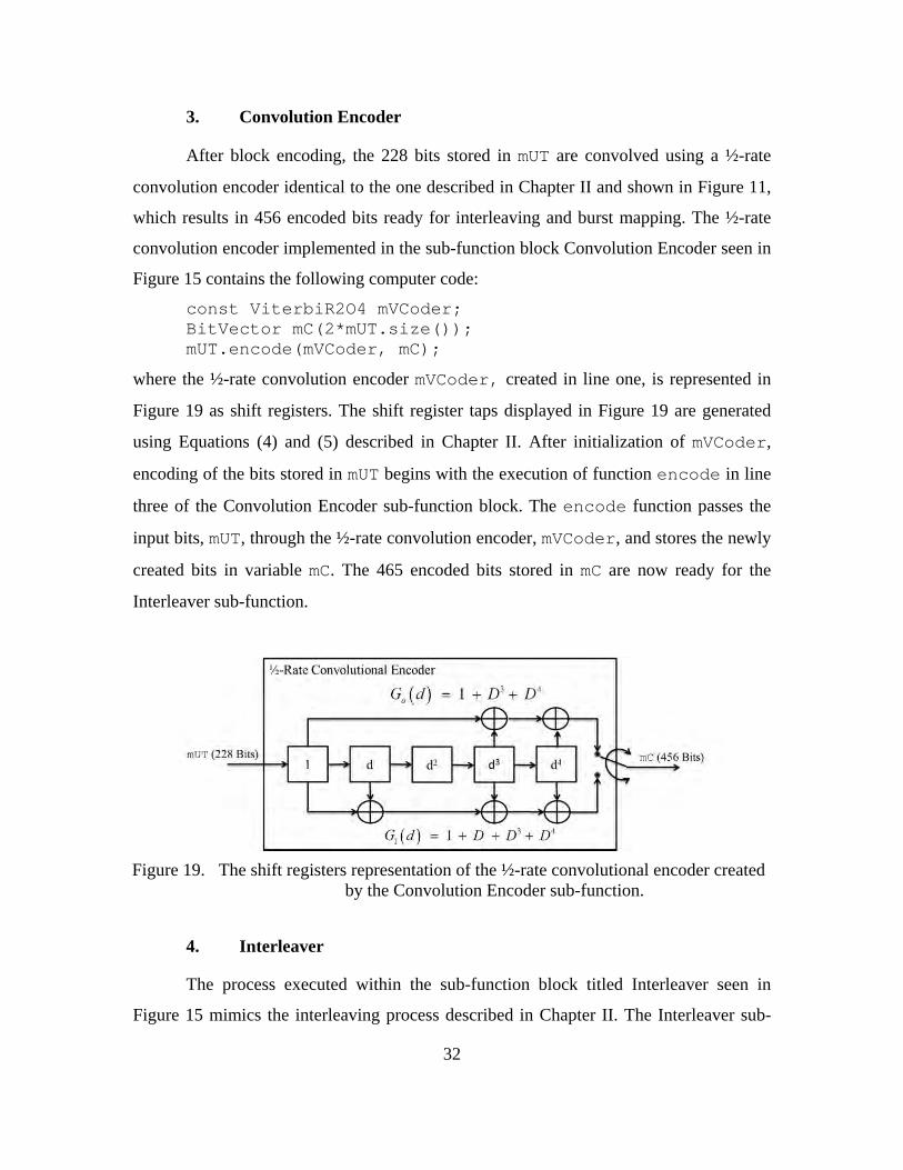
32
3. Convolution Encoder
After block encoding, the 228 bits stored in mUT are convolved using a ½-rate
convolution encoder identical to the one described in Chapter II and shown in Figure 11,
which results in 456 encoded bits ready for interleaving and burst mapping. The ½-rate
convolution encoder implemented in the sub-function block Convolution Encoder seen in
Figure 15 contains the following computer code:
const ViterbiR2O4 mVCoder; BitVector mC(2*mUT.size()); mUT.encode(mVCoder, mC);
where the ½-rate convolution encoder mVCoder, created in line one, is represented in
Figure 19 as shift registers. The shift register taps displayed in Figure 19 are generated
using Equations (4) and (5) described in Chapter II. After initialization of mVCoder,
encoding of the bits stored in mUT begins with the execution of function encode in line
three of the Convolution Encoder sub-function block. The encode function passes the
input bits, mUT, through the ½-rate convolution encoder, mVCoder, and stores the newly
created bits in variable mC. The 465 encoded bits stored in mC are now ready for the
Interleaver sub-function.
Figure 19. The shift registers representation of the ½-rate convolutional encoder created by the Convolution Encoder sub-function.
4. Interleaver
The process executed within the sub-function block titled Interleaver seen in
Figure 15 mimics the interleaving process described in Chapter II. The Interleaver sub-
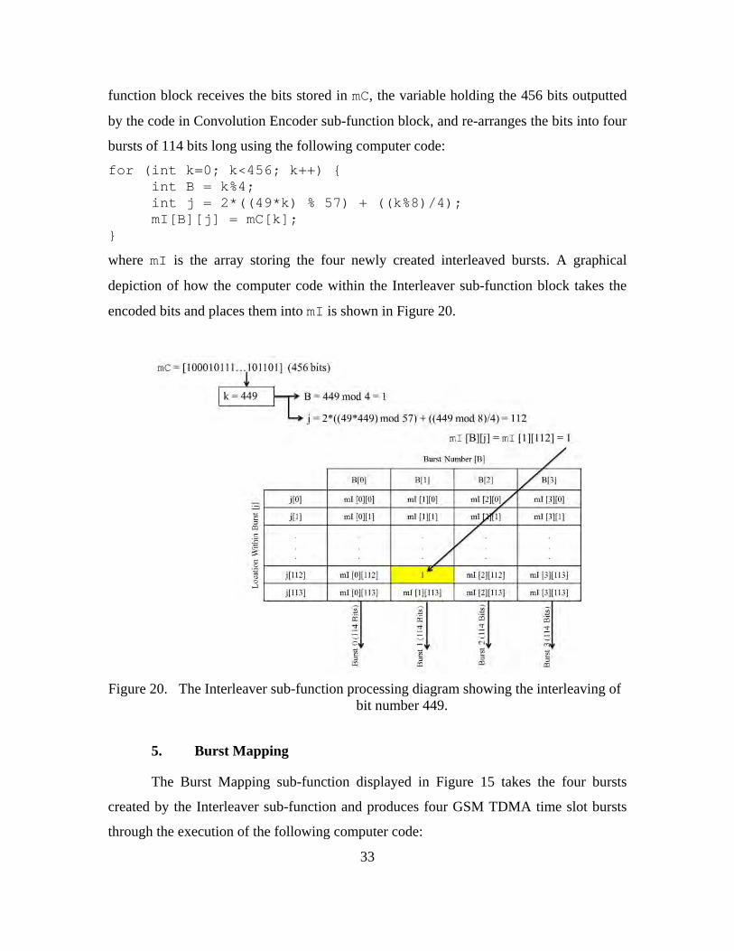
33
function block receives the bits stored in mC, the variable holding the 456 bits outputted
by the code in Convolution Encoder sub-function block, and re-arranges the bits into four
bursts of 114 bits long using the following computer code:
for (int k=0; k<456; k++) { int B = k%4; int j = 2*((49*k) % 57) + ((k%8)/4); mI[B][j] = mC[k]; }
where mI is the array storing the four newly created interleaved bursts. A graphical
depiction of how the computer code within the Interleaver sub-function block takes the
encoded bits and places them into mI is shown in Figure 20.
Figure 20. The Interleaver sub-function processing diagram showing the interleaving of bit number 449.
5. Burst Mapping
The Burst Mapping sub-function displayed in Figure 15 takes the four bursts
created by the Interleaver sub-function and produces four GSM TDMA time slot bursts
through the execution of the following computer code:
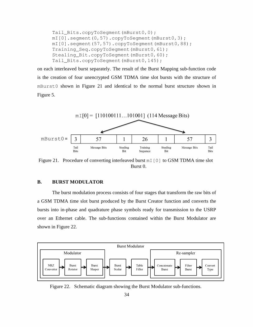
34
Tail_Bits.copyToSegment(mBurst0,0); mI[0].segment(0,57).copyToSegment(mBurst0,3); mI[0].segment(57,57).copyToSegment(mBurst0,88); Training_Seq.copyToSegment(mBurst0,61); Stealing_Bit.copyToSegment(mBurst0,60); Tail_Bits.copyToSegment(mBurst0,145);
on each interleaved burst separately. The result of the Burst Mapping sub-function code
is the creation of four unencrypted GSM TDMA time slot bursts with the structure of
mBurst0 shown in Figure 21 and identical to the normal burst structure shown in
Figure 5.
Figure 21. Procedure of converting interleaved burst mI[0] to GSM TDMA time slot Burst 0.
B. BURST MODULATOR
The burst modulation process consists of four stages that transform the raw bits of
a GSM TDMA time slot burst produced by the Burst Creator function and converts the
bursts into in-phase and quadrature phase symbols ready for transmission to the USRP
over an Ethernet cable. The sub-functions contained within the Burst Modulator are
shown in Figure 22.
Figure 22. Schematic diagram showing the Burst Modulator sub-functions.
35
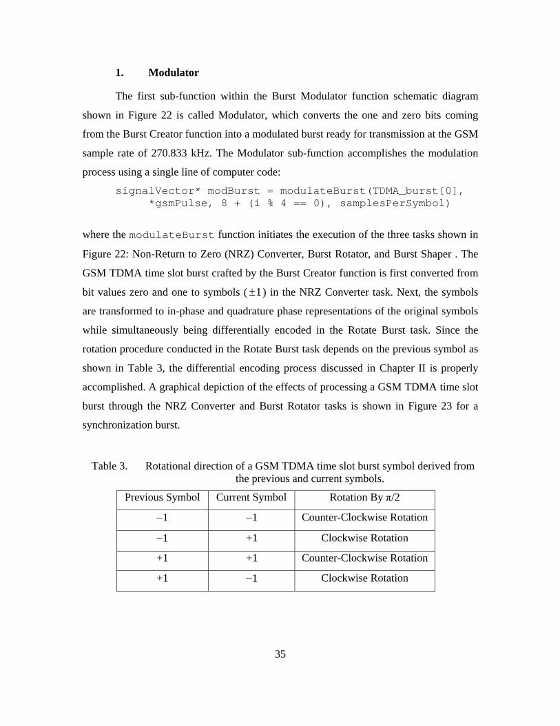
1. Modulator
The first sub-function within the Burst Modulator function schematic diagram
shown in Figure 22 is called Modulator, which converts the one and zero bits coming
from the Burst Creator function into a modulated burst ready for transmission at the GSM
sample rate of 270.833 kHz. The Modulator sub-function accomplishes the modulation
process using a single line of computer code:
signalVector* modBurst = modulateBurst(TDMA_burst[0], *gsmPulse, 8 + (i % 4 == 0), samplesPerSymbol)
where the modulateBurst function initiates the execution of the three tasks shown in
Figure 22: Non-Return to Zero (NRZ) Converter, Burst Rotator, and Burst Shaper . The
GSM TDMA time slot burst crafted by the Burst Creator function is first converted from
bit values zero and one to symbols ( 1 ) in the NRZ Converter task. Next, the symbols
are transformed to in-phase and quadrature phase representations of the original symbols
while simultaneously being differentially encoded in the Rotate Burst task. Since the
rotation procedure conducted in the Rotate Burst task depends on the previous symbol as
shown in Table 3, the differential encoding process discussed in Chapter II is properly
accomplished. A graphical depiction of the effects of processing a GSM TDMA time slot
burst through the NRZ Converter and Burst Rotator tasks is shown in Figure 23 for a
synchronization burst.
Table 3. Rotational direction of a GSM TDMA time slot burst symbol derived from the previous and current symbols.
Previous Symbol Current Symbol Rotation By π/2
1 1 Counter-Clockwise Rotation
1 +1 Clockwise Rotation
+1 +1 Counter-Clockwise Rotation
+1 1 Clockwise Rotation
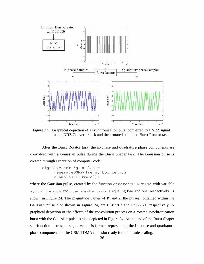
36
Figure 23. Graphical depiction of a synchronization burst converted to a NRZ signal using NRZ Converter task and then rotated using the Burst Rotator task.
After the Burst Rotator task, the in-phase and quadrature phase components are
convolved with a Gaussian pulse during the Burst Shaper task. The Gaussian pulse is
created through execution of computer code:
signalVector *gsmPulse = generateGSMPulse(symbol_length, mSamplesPerSymbol);
where the Gaussian pulse, created by the function generateGSMPulse with variable
symbol_length and mSamplesPerSymbol equaling two and one, respectively, is
shown in Figure 24. The magnitude values of W and Z, the pulses contained within the
Gaussian pulse plot shown in Figure 24, are 0.182762 and 0.966021, respectively. A
graphical depiction of the effects of the convolution process on a rotated synchronization
burst with the Gaussian pulse is also depicted in Figure 24. At the end of the Burst Shaper
sub-function process, a signal vector is formed representing the in-phase and quadrature
phase components of the GSM TDMA time slot ready for amplitude scaling.

37
Figure 24. Graphical representation of the effects of convolving the in-phase and quadrature phase samples from the Burst Rotator task with a Gaussian pulse.
2. Burst Scalar
The next stage of the Burst Modulator function, Burst Scalar, increases the
amplitude of the modulated GSM TDMA time slot burst through the multiplication of the
signal by 9600, the default value used by OpenBTS [1]. This scaling factor allows the
software to dynamically change the amplitude of the signal without having to change the
gain factor configured on the USRP. The ability to dynamically change the signal
amplitude allows the transmitter to match the power required to transmit the GSM
TDMA time slot burst from the USRP to the BTS. The code contained within the Burst
Scalar task block is:
scaleVector(*modBurst,fullScaleInputValue);
where the variable fullScaleInputValue equals 9600.
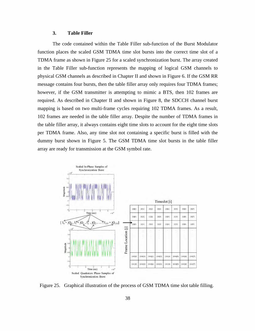
38
3. Table Filler
The code contained within the Table Filler sub-function of the Burst Modulator
function places the scaled GSM TDMA time slot bursts into the correct time slot of a
TDMA frame as shown in Figure 25 for a scaled synchronization burst. The array created
in the Table Filler sub-function represents the mapping of logical GSM channels to
physical GSM channels as described in Chapter II and shown in Figure 6. If the GSM RR
message contains four bursts, then the table filler array only requires four TDMA frames;
however, if the GSM transmitter is attempting to mimic a BTS, then 102 frames are
required. As described in Chapter II and shown in Figure 8, the SDCCH channel burst
mapping is based on two multi-frame cycles requiring 102 TDMA frames. As a result,
102 frames are needed in the table filler array. Despite the number of TDMA frames in
the table filler array, it always contains eight time slots to account for the eight time slots
per TDMA frame. Also, any time slot not containing a specific burst is filled with the
dummy burst shown in Figure 5. The GSM TDMA time slot bursts in the table filler
array are ready for transmission at the GSM symbol rate.
Figure 25. Graphical illustration of the process of GSM TDMA time slot table filling.
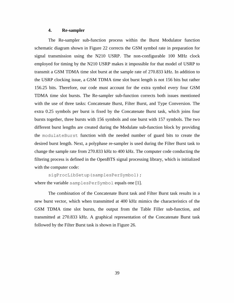
39
4. Re-sampler
The Re-sampler sub-function process within the Burst Modulator function
schematic diagram shown in Figure 22 corrects the GSM symbol rate in preparation for
signal transmission using the N210 USRP. The non-configurable 100 MHz clock
employed for timing by the N210 USRP makes it impossible for that model of USRP to
transmit a GSM TDMA time slot burst at the sample rate of 270.833 kHz. In addition to
the USRP clocking issue, a GSM TDMA time slot burst length is not 156 bits but rather
156.25 bits. Therefore, our code must account for the extra symbol every four GSM
TDMA time slot bursts. The Re-sampler sub-function corrects both issues mentioned
with the use of three tasks: Concatenate Burst, Filter Burst, and Type Conversion. The
extra 0.25 symbols per burst is fixed by the Concatenate Burst task, which joins four
bursts together, three bursts with 156 symbols and one burst with 157 symbols. The two
different burst lengths are created during the Modulate sub-function block by providing
the modulateBurst function with the needed number of guard bits to create the
desired burst length. Next, a polyphase re-sampler is used during the Filter Burst task to
change the sample rate from 270.833 kHz to 400 kHz. The computer code conducting the
filtering process is defined in the OpenBTS signal processing library, which is initialized
with the computer code:
sigProcLibSetup(samplesPerSymbol);
where the variable samplesPerSymbol equals one [1].
The combination of the Concatenate Burst task and Filter Burst task results in a
new burst vector, which when transmitted at 400 kHz mimics the characteristics of the
GSM TDMA time slot bursts, the output from the Table Filler sub-function, and
transmitted at 270.833 kHz. A graphical representation of the Concatenate Burst task
followed by the Filter Burst task is shown in Figure 26.
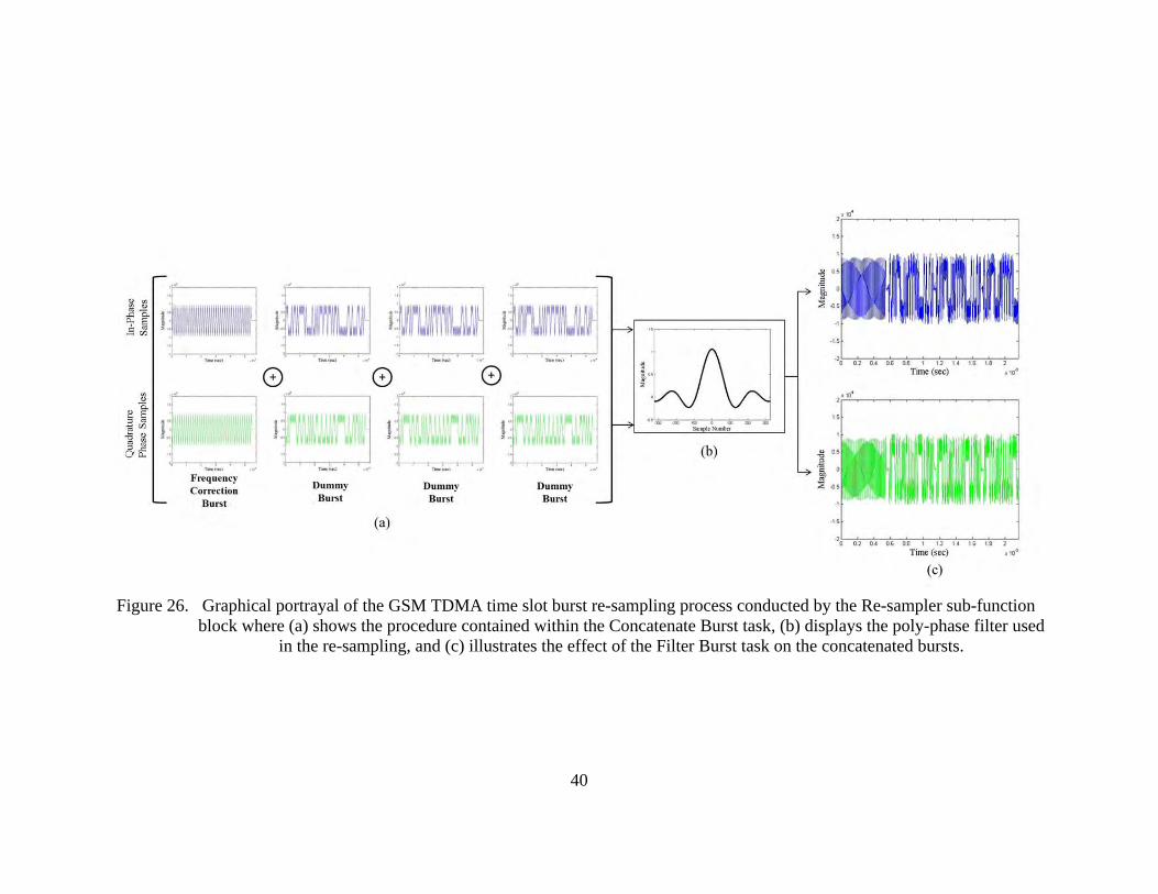
40
Figure 26. Graphical portrayal of the GSM TDMA time slot burst re-sampling process conducted by the Re-sampler sub-function block where (a) shows the procedure contained within the Concatenate Burst task, (b) displays the poly-phase filter used
in the re-sampling, and (c) illustrates the effect of the Filter Burst task on the concatenated bursts.
41
The last task within the Re-Sample sub-function is Type Conversion, which
changes the C++ type float to C++ type short. During all the Burst Modulator sub-
functions until the Type Conversion task, all in-phase and quadrature phase samples are
of C++ type float, which means each phase sample is consisting of four bytes. These in-
phase and quadrature phase samples are converted to C++ type short, which consists of
only two bytes for each phase sample. This decrease in byte size used to represent each
sample allows the packaging of twice as many samples into the IP packets sent to the
USRP over an Ethernet cable. The end result of the type conversion is faster arrival rates
of samples at the USRP.
C. BURST TRANSMITTER
The Burst Transmitter function takes the in-phase and quadrature phase samples
from the Re-sampler sub-function and packages them into packets for transmission over
the Ethernet cable connecting the computer to the USRP. Once the IP packets reach the
USRP, the onboard digital up converter (DUC) interpolates the digital signal and
transitions the signal from digital to analog through the use of a 16-bit digital-to-analog
converter (DAC). Finally, the DAC output is filtered to prevent aliasing, amplified, and
transmitted as an analog waveform [21], [22].
1. USRP Initialization Coding
Prior to any modulation or transmission of any GSM TDMA time slot burst, our
code must first initiate communication with the USRP. The code establishing initial
communication and setting the starting parameters for the USRP is:
uhd::usrp::multi_usrp::sptr usrp; usrp = uhd::usrp::multi_usrp::make(args); uhd::stream_args_t stream_args; stream_args.cpu_format = “sc16”; uhd::tx_streamer::sptr tx_stream = usrp-> get_tx_stream(stream_args); usrp->set_tx_rate(tx_sample_rate); double actual_tx_rate = usrp->get_tx_rate(); usrp->set_tx_gain(tx_gain); uhd::tune_result_t tr = usrp->set_tx_freq(tx_freq); double actual_tx_freq = usrp->get_tx_freq();
42
usrp->set_tx_antenna(ant);
where the values used for variables tx_sample_rate, tx_gain, tx_freq, and
ant used for testing our GSM transmitter code are displayed in Table 4. The reason for
the two different frequencies for the tx_freq variable is because we test our GSM
transmitter code by sending messages on both an uplink and downlink channel. The
particular downlink and uplink frequencies shown in Table 4 equate to the absolute radio-
frequency channel number (ARFCN) 17 for the downlink and ARFCN 3 for the uplink.
The Naval Postgraduate School (NPS) test range BTS uses ARFCN 3; therefore, we
chose that same channel for the uplink so we could attempt to have our transmitter code
send RR messages to the NPS BTS. We chose ARFCN 17 for the uplink in order to
minimize interference with the NPS BTS. After the initialization of the USRP, samples
can be transmitted from the computer to the USRP over the Ethernet connection.
Table 4. USRP variables and their values used during testing of GSM transmitter.
GSM Transmitter USRP Variables GSM Transmitter USRP Variable Values
tx_sample_rate 400 kHz
tx_gain 15 dB
tx_freq Downlink Channel = 938.4 MHz
Uplink Channel = 890.6 MHz
Ant “TX/RX”
2. Transmission Coding
The code, within the Burst Transmitter sub-function called Ethernet, which
packages up the in-phase and quadrature phase samples and transmits the packets over
the Ethernet connection is:
size_t num_tx_samps = tx_stream-> send(smpls_out + 192 * 2, num_resmpl – 192, md, uhd::device::SEND_MODE_FULL_BUFF)
where the first variable input to the function send identifies the starting location within
the array of complex samples coming from the Burst Modulator function that is sent to
43
the USRP. The second variable input to the function send identifies how many complex
samples from the starting location are sent to the USRP. The purpose for the offset in the
start of the first sample is because the Re-sampler sub-function uses the last 384 samples
from the previously re-sampled concatenated bursts as input into the next newly created
burst. Since those 384 samples were previously transmitted, an offset is introduced prior
to sending the samples to the USRP. The SEND_MODE_FULL_BUFF input to the
function send in the Ethernet sub-function code informs the computer to fragment the
received samples for transmission to the USRP into the maximum sized packets in order
to minimize delay between the computer and USRP [21].
Once the packaged complex signal reaches the USRP, it is de-interleaved by the
field-programmable gate array (FPGA) in order to separate the in-phase and quadrature
phase components. Next, the individual phase components are digitally up-converted
converted to an analog signal and filtered in parallel. Finally, the signals are mixed to the
desired carrier frequency. A schematic of the signal flow through the USRP is shown in
Figure 27 [23].
Figure 27. Block diagram showing the process flow of in-phase and quadrature phase samples though the USRP transmitter (after [23]).
A concise overview of all of the processes, sub-processes and tasks contained in
our GSM transmitter shown in Figure 15 was described in this chapter. First, we
described the Burst Creator block computer code, which transforms the 184 bit LAPDm
frame into four GSM TDMA time slot bursts ready for modulation. Next, we explained
the Burst Modulator block computer code and showed the procedure of transforming a

44
GSM TDMA time slot burst into a re-sampled burst ready for the USRP to transmit at the
sample rate of 400 kHz. Finally, we explored the process the complex samples undergo
after entering the USRP.

45
V. TESTING AND EVALUATION
The testing of the proposed GSM transmitter first requires a GSM receiver
capable of collecting, demodulating, and decoding a GSM message. Currently, the GSM
receivers with the aforementioned capabilities require a GSM transmitting device to
modulate all the bursts a BTS sends over its BCH because the GSM receivers
synchronize in time and frequency with the frequency correction bursts and
synchronization bursts prior to decoding any other messages. We demonstrate that our
GSM transmitter code properly transmits a GSM burst by first configuring the GSM
transmitter code to broadcast all the messages sent over a BTS BCH. Next, we test the
handover failure message transmission to validate that the message is encoded and
transmitted correctly by the GSM transmitter we developed. Finally, we implement a
queuing process within our code to trigger the sending of a handover failure message
after a handover to UTRAN message is received.
The equipment used in this thesis to create and evaluate the proposed GSM
transmitter includes: (i) a fully functioning GSM/UMTS network, (ii) the ASCOM TEMS
GSM/UMTS message collection equipment, (iii) an Agilient Technologies Signal
Analyzer, (iv) a Samsung Galaxy S2 smart phone and (v) Ettus N210 and B100 USRPs.
The GSM/UMTS network consists of a GSM BTS and a UMTS Node B, which are both
located on the NPS campus but connected to a BSC, RNC and MSC positioned at the
Yuma Proving Ground. This NPS GSM/UMTS heterogeneous network provided us a
fully functioning and commercial-equivilent network capable of UTRAN handovers.
The ASCOM TEMS GSM/UMTS message collection equipment gives us the
ability to collect and decode any GSM/UMTS layer two/three message, which we used to
correctly format GSM messages for the GSM transmitter to send. We also utilized the
Agilient Technologies Signal Analyzer to test that the USRP was transmitting at the
correct center frequency. The Samsung Galaxy S2 smart phone was used to collect the
Inter System to UTRAN handover command from the NPS BTS and pass it to the GSM
transmitter. Finally, the N210 USRP was used as the transmitter for the GSM transmitter
46
code we developed, and the B100 USRP was utilized as the GSM receiver that collected
the messages sent by the GSM transmitter.
A. BTS TRANSMISSION OF BCH
The first proof-of-concept test involves transmitting the BCH and CCCH
messages shown in Figure 7. The devices available for GSM collection initialize all
collection off the frequency correction bursts and synchronization bursts. If a known
GSM collection device properly demodulates and decodes the broadcast messages
coming from our GSM transmitter code, then we have demonstrated the capability of our
GSM transmitter to correctly encode and modulate a GSM burst.
1. Code Creation
The code for the GSM transmitter must contain the ability to transmit the
frequency correction bursts, synchronization bursts, dummy bursts, and normal bursts in
order to successfully transmit the BCH and CCCH messages. All the aforementioned
burst types are modulated, re-sampled and transmitted as discussed in Chapter IV, but
only the normal burst uses Equation (1) as its generator polynomial in the block coding
process described in Chapter IV. The frequency correction bursts and dummy bursts are
not block coded, and the synchronization burst uses 1( )g D from Equation (2) as its
generated polynomial. The C++ computer code generated for this experiment is shown in
Appendix B.
2. Setup
Prior to transmitting any GSM burst, we identified and created the BCCH
message bursts and the PCH bursts. We also found a GSM receiver capable of
demodulating and displaying the received messages from our GSM transmitter. The GSM
receiver we chose is Airprobe’s GSM-receiver.
a. ASCOM TEMS GSM Message Collection
The creation of properly formatted System Information Type 1, 2,
2quarter, 3 and 4 RR messages to transmit on the BCCH was a requirement because

47
Airprobe’s GSM-receiver needs properly formatted messages to correctly reassemble the
contents. We used ASCOM TEMS Investigation hardware and software to collect the
Type 1, 2, 2quarter, 3 and 4 RR messages sent over the NPS GSM lab BTS BCH. The
collection of a System Information Type 1 RR message sent over the NPS GSM BTS
BCH is shown in Figure 28. Additionally, we collected PCH messages from the NPS
GSM BTS using the ASCOM TEMS equipment to transmit in the CCCH time slots.
Figure 28. Example capture of ASCOM TEMS message collection equipment capturing (a) the System Information Type 1 RR message, and (b) the message contents
of the System Information Type 1 RR message.
b. Airprobe’s GSM-receiver
Next, we needed to find a GSM receiver capable of collecting our GSM
transmitter and providing viewable results. To accomplish this task we chose Airprobe’s
GSM-receiver software coupled with Wireshark as the message viewing software and the
B100 USRP as the radio frequency collection device. We chose Airprobe’s GSM-
receiver because it displays all the received transmitted messages, while comparable
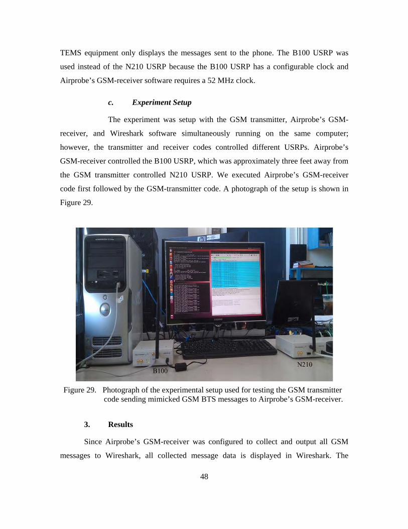
48
TEMS equipment only displays the messages sent to the phone. The B100 USRP was
used instead of the N210 USRP because the B100 USRP has a configurable clock and
Airprobe’s GSM-receiver software requires a 52 MHz clock.
c. Experiment Setup
The experiment was setup with the GSM transmitter, Airprobe’s GSM-
receiver, and Wireshark software simultaneously running on the same computer;
however, the transmitter and receiver codes controlled different USRPs. Airprobe’s
GSM-receiver controlled the B100 USRP, which was approximately three feet away from
the GSM transmitter controlled N210 USRP. We executed Airprobe’s GSM-receiver
code first followed by the GSM-transmitter code. A photograph of the setup is shown in
Figure 29.
Figure 29. Photograph of the experimental setup used for testing the GSM transmitter code sending mimicked GSM BTS messages to Airprobe’s GSM-receiver.
3. Results
Since Airprobe’s GSM-receiver was configured to collect and output all GSM
messages to Wireshark, all collected message data is displayed in Wireshark. The
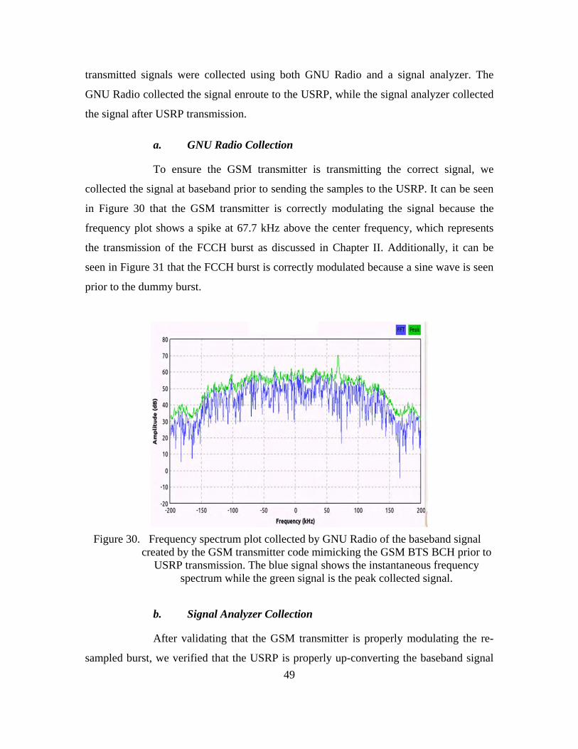
49
transmitted signals were collected using both GNU Radio and a signal analyzer. The
GNU Radio collected the signal enroute to the USRP, while the signal analyzer collected
the signal after USRP transmission.
a. GNU Radio Collection
To ensure the GSM transmitter is transmitting the correct signal, we
collected the signal at baseband prior to sending the samples to the USRP. It can be seen
in Figure 30 that the GSM transmitter is correctly modulating the signal because the
frequency plot shows a spike at 67.7 kHz above the center frequency, which represents
the transmission of the FCCH burst as discussed in Chapter II. Additionally, it can be
seen in Figure 31 that the FCCH burst is correctly modulated because a sine wave is seen
prior to the dummy burst.
Figure 30. Frequency spectrum plot collected by GNU Radio of the baseband signal created by the GSM transmitter code mimicking the GSM BTS BCH prior to
USRP transmission. The blue signal shows the instantaneous frequency spectrum while the green signal is the peak collected signal.
b. Signal Analyzer Collection
After validating that the GSM transmitter is properly modulating the re-
sampled burst, we verified that the USRP is properly up-converting the baseband signal
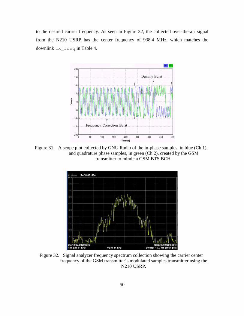
50
to the desired carrier frequency. As seen in Figure 32, the collected over-the-air signal
from the N210 USRP has the center frequency of 938.4 MHz, which matches the
downlink tx_freq in Table 4.
Figure 31. A scope plot collected by GNU Radio of the in-phase samples, in blue (Ch 1), and quadrature phase samples, in green (Ch 2), created by the GSM
transmitter to mimic a GSM BTS BCH.
Figure 32. Signal analyzer frequency spectrum collection showing the carrier center frequency of the GSM transmitter’s modulated samples transmitter using the
N210 USRP.
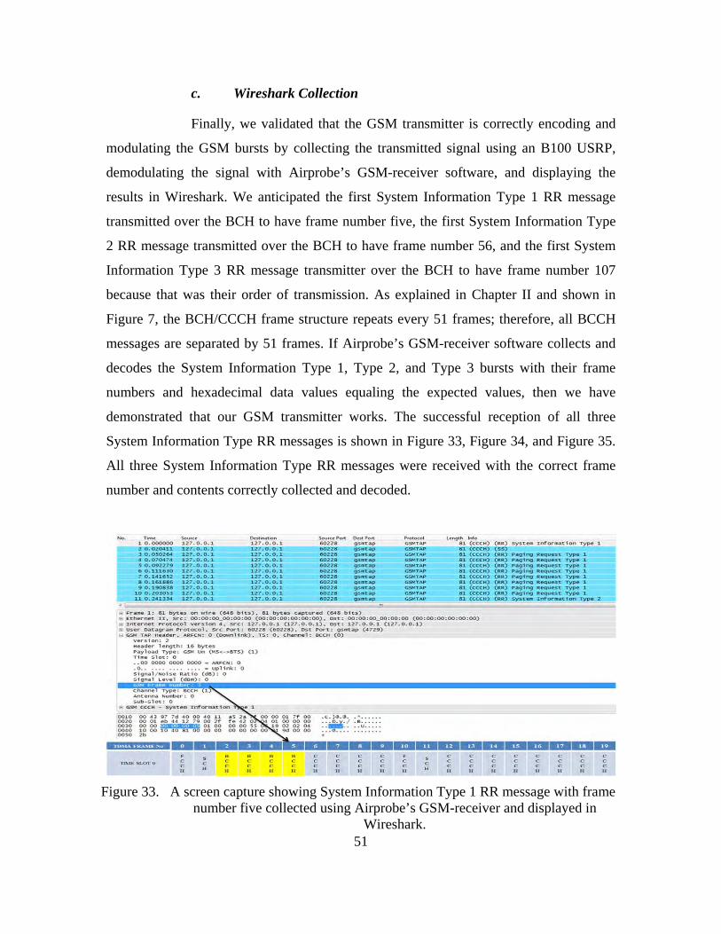
51
c. Wireshark Collection
Finally, we validated that the GSM transmitter is correctly encoding and
modulating the GSM bursts by collecting the transmitted signal using an B100 USRP,
demodulating the signal with Airprobe’s GSM-receiver software, and displaying the
results in Wireshark. We anticipated the first System Information Type 1 RR message
transmitted over the BCH to have frame number five, the first System Information Type
2 RR message transmitted over the BCH to have frame number 56, and the first System
Information Type 3 RR message transmitter over the BCH to have frame number 107
because that was their order of transmission. As explained in Chapter II and shown in
Figure 7, the BCH/CCCH frame structure repeats every 51 frames; therefore, all BCCH
messages are separated by 51 frames. If Airprobe’s GSM-receiver software collects and
decodes the System Information Type 1, Type 2, and Type 3 bursts with their frame
numbers and hexadecimal data values equaling the expected values, then we have
demonstrated that our GSM transmitter works. The successful reception of all three
System Information Type RR messages is shown in Figure 33, Figure 34, and Figure 35.
All three System Information Type RR messages were received with the correct frame
number and contents correctly collected and decoded.
Figure 33. A screen capture showing System Information Type 1 RR message with frame number five collected using Airprobe’s GSM-receiver and displayed in
Wireshark.
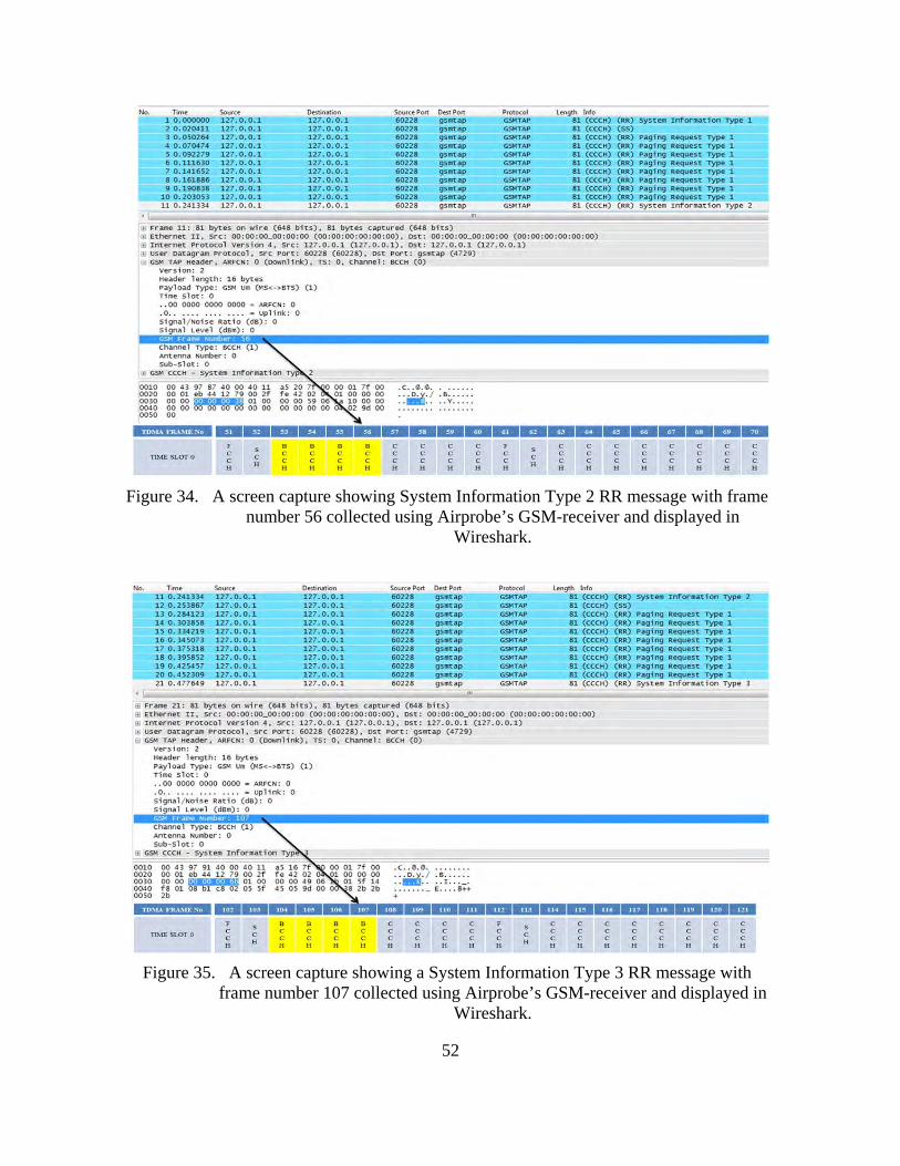
52
Figure 34. A screen capture showing System Information Type 2 RR message with frame number 56 collected using Airprobe’s GSM-receiver and displayed in
Wireshark.
Figure 35. A screen capture showing a System Information Type 3 RR message with frame number 107 collected using Airprobe’s GSM-receiver and displayed in
Wireshark.
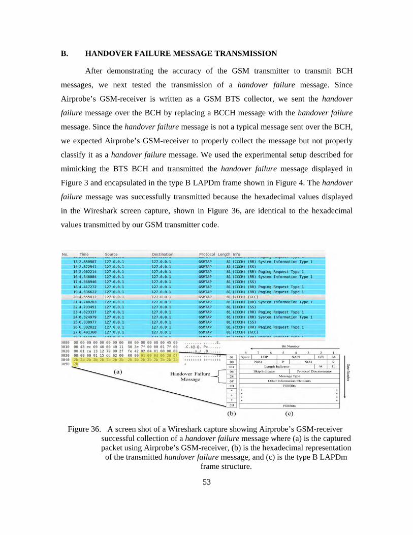
53
B. HANDOVER FAILURE MESSAGE TRANSMISSION
After demonstrating the accuracy of the GSM transmitter to transmit BCH
messages, we next tested the transmission of a handover failure message. Since
Airprobe’s GSM-receiver is written as a GSM BTS collector, we sent the handover
failure message over the BCH by replacing a BCCH message with the handover failure
message. Since the handover failure message is not a typical message sent over the BCH,
we expected Airprobe’s GSM-receiver to properly collect the message but not properly
classify it as a handover failure message. We used the experimental setup described for
mimicking the BTS BCH and transmitted the handover failure message displayed in
Figure 3 and encapsulated in the type B LAPDm frame shown in Figure 4. The handover
failure message was successfully transmitted because the hexadecimal values displayed
in the Wireshark screen capture, shown in Figure 36, are identical to the hexadecimal
values transmitted by our GSM transmitter code.
Figure 36. A screen shot of a Wireshark capture showing Airprobe’s GSM-receiver successful collection of a handover failure message where (a) is the captured packet using Airprobe’s GSM-receiver, (b) is the hexadecimal representation of the transmitted handover failure message, and (c) is the type B LAPDm
frame structure.
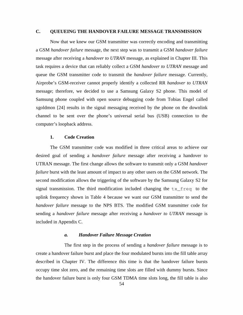
54
C. QUEUEING THE HANDOVER FAILURE MESSAGE TRANSMISSION
Now that we knew our GSM transmitter was correctly encoding and transmitting
a GSM handover failure message, the next step was to transmit a GSM handover failure
message after receiving a handover to UTRAN message, as explained in Chapter III. This
task requires a device that can reliably collect a GSM handover to UTRAN message and
queue the GSM transmitter code to transmit the handover failure message. Currently,
Airprobe’s GSM-receiver cannot properly identify a collected RR handover to UTRAN
message; therefore, we decided to use a Samsung Galaxy S2 phone. This model of
Samsung phone coupled with open source debugging code from Tobias Engel called
xgoldmon [24] results in the signal messaging received by the phone on the downlink
channel to be sent over the phone’s universal serial bus (USB) connection to the
computer’s loopback address.
1. Code Creation
The GSM transmitter code was modified in three critical areas to achieve our
desired goal of sending a handover failure message after receiving a handover to
UTRAN message. The first change allows the software to transmit only a GSM handover
failure burst with the least amount of impact to any other users on the GSM network. The
second modification allows the triggering of the software by the Samsung Galaxy S2 for
signal transmission. The third modification included changing the tx_freq to the
uplink frequency shown in Table 4 because we want our GSM transmitter to send the
handover failure message to the NPS BTS. The modified GSM transmitter code for
sending a handover failure message after receiving a handover to UTRAN message is
included in Appendix C.
a. Handover Failure Message Creation
The first step in the process of sending a handover failure message is to
create a handover failure burst and place the four modulated bursts into the fill table array
described in Chapter IV. The difference this time is that the handover failure bursts
occupy time slot zero, and the remaining time slots are filled with dummy bursts. Since
the handover failure burst is only four GSM TDMA time slots long, the fill table is also

55
only four TDMA time slots in length. Next, we minimize interference with other users on
the GSM network by only amplifying the handover failure bursts and dummy bursts
immediately before and after the handover failure bursts. We have to amplify the
surrounding dummy bursts because the resampling process uses those bursts in the
resampling of the handover failure bursts. If we chose not to amplify the surrounding
dummy burst, then the resampling process truncates the handover failure bursts.
b. Transmission Queuing Using Packet Capture Library (PCAP) Code
PCAP provides us with the ability to listen on the loopback address of the
computer and analyze the GSM signaling messages sent from the Samsung Galaxy S2
phone to the computer. We identify that handover to UTRAN message was received by
the phone because the bytes in positions 122 to 126 of the message sent by the phone to
the computer’s loopback address equate to the hexadecimal values 0663. Once our GSM
transmitter code determines the handover to UTRAN message was received, it queues the
transmitter section of the code to immediately modulate the handover failure message
and transmit the bursts via the USRP.
c. Setup
The setup for transmission of a queued GSM handover failure message
starts with initialization of the Samsung Galaxy S2 phone and the xgoldmon code as
provided in Appendix A. Once the Samsung phone and xgoldmon code are running, the
next step is to start the modified GSM transmitter code, which initializes the N210 USRP
and begins waiting for the handover to UTRAN message. We encourage the phone to
conduct a handover to UTRAN by initializing the phone to use only the GSM network,
which is accomplished by changing the phone’s network configuration settings to GSM
only. After the phone establishes connection on the GSM network, we change the
phone’s network settings to allow connections to both the GSM and UMTS networks.
Immediately after changing the settings and while the phone is still associated with the
GSM network, we initiate a call on the GSM network. After call establishment, we wait
for the network to transition the phone to the UMTS network by sending a handover to
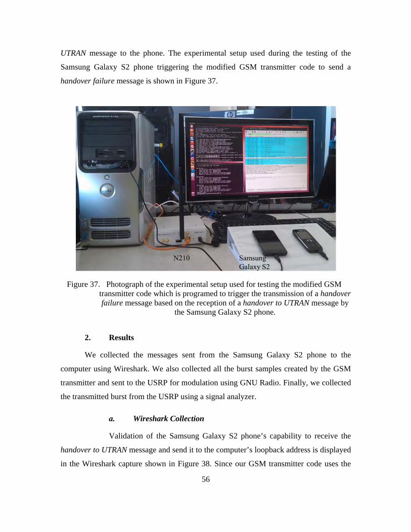
56
UTRAN message to the phone. The experimental setup used during the testing of the
Samsung Galaxy S2 phone triggering the modified GSM transmitter code to send a
handover failure message is shown in Figure 37.
Figure 37. Photograph of the experimental setup used for testing the modified GSM transmitter code which is programed to trigger the transmission of a handover failure message based on the reception of a handover to UTRAN message by
the Samsung Galaxy S2 phone.
2. Results
We collected the messages sent from the Samsung Galaxy S2 phone to the
computer using Wireshark. We also collected all the burst samples created by the GSM
transmitter and sent to the USRP for modulation using GNU Radio. Finally, we collected
the transmitted burst from the USRP using a signal analyzer.
a. Wireshark Collection
Validation of the Samsung Galaxy S2 phone’s capability to receive the
handover to UTRAN message and send it to the computer’s loopback address is displayed
in the Wireshark capture shown in Figure 38. Since our GSM transmitter code uses the
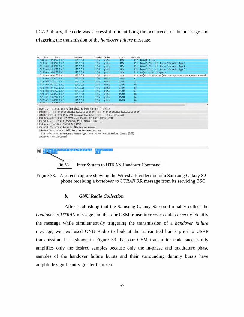
57
PCAP library, the code was successful in identifying the occurrence of this message and
triggering the transmission of the handover failure message.
Figure 38. A screen capture showing the Wireshark collection of a Samsung Galaxy S2 phone receiving a handover to UTRAN RR message from its servicing BSC.
b. GNU Radio Collection
After establishing that the Samsung Galaxy S2 could reliably collect the
handover to UTRAN message and that our GSM transmitter code could correctly identify
the message while simultaneously triggering the transmission of a handover failure
message, we next used GNU Radio to look at the transmitted bursts prior to USRP
transmission. It is shown in Figure 39 that our GSM transmitter code successfully
amplifies only the desired samples because only the in-phase and quadrature phase
samples of the handover failure bursts and their surrounding dummy bursts have
amplitude significantly greater than zero.
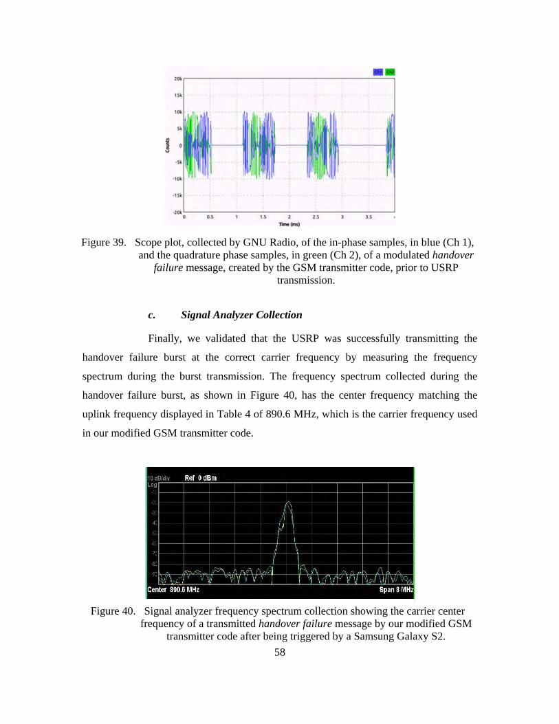
58
Figure 39. Scope plot, collected by GNU Radio, of the in-phase samples, in blue (Ch 1), and the quadrature phase samples, in green (Ch 2), of a modulated handover
failure message, created by the GSM transmitter code, prior to USRP transmission.
c. Signal Analyzer Collection
Finally, we validated that the USRP was successfully transmitting the
handover failure burst at the correct carrier frequency by measuring the frequency
spectrum during the burst transmission. The frequency spectrum collected during the
handover failure burst, as shown in Figure 40, has the center frequency matching the
uplink frequency displayed in Table 4 of 890.6 MHz, which is the carrier frequency used
in our modified GSM transmitter code.
Figure 40. Signal analyzer frequency spectrum collection showing the carrier center frequency of a transmitted handover failure message by our modified GSM
transmitter code after being triggered by a Samsung Galaxy S2.
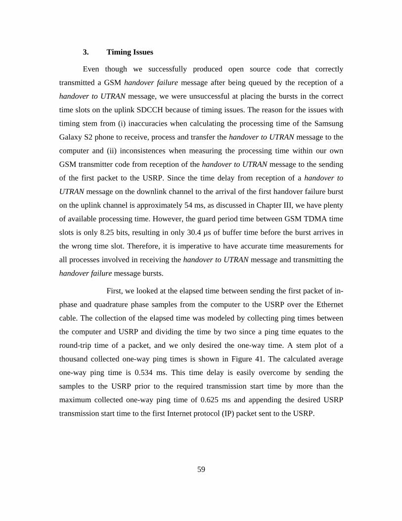
59
3. Timing Issues
Even though we successfully produced open source code that correctly
transmitted a GSM handover failure message after being queued by the reception of a
handover to UTRAN message, we were unsuccessful at placing the bursts in the correct
time slots on the uplink SDCCH because of timing issues. The reason for the issues with
timing stem from (i) inaccuracies when calculating the processing time of the Samsung
Galaxy S2 phone to receive, process and transfer the handover to UTRAN message to the
computer and (ii) inconsistences when measuring the processing time within our own
GSM transmitter code from reception of the handover to UTRAN message to the sending
of the first packet to the USRP. Since the time delay from reception of a handover to
UTRAN message on the downlink channel to the arrival of the first handover failure burst
on the uplink channel is approximately 54 ms, as discussed in Chapter III, we have plenty
of available processing time. However, the guard period time between GSM TDMA time
slots is only 8.25 bits, resulting in only 30.4 µs of buffer time before the burst arrives in
the wrong time slot. Therefore, it is imperative to have accurate time measurements for
all processes involved in receiving the handover to UTRAN message and transmitting the
handover failure message bursts.
First, we looked at the elapsed time between sending the first packet of in-
phase and quadrature phase samples from the computer to the USRP over the Ethernet
cable. The collection of the elapsed time was modeled by collecting ping times between
the computer and USRP and dividing the time by two since a ping time equates to the
round-trip time of a packet, and we only desired the one-way time. A stem plot of a
thousand collected one-way ping times is shown in Figure 41. The calculated average
one-way ping time is 0.534 ms. This time delay is easily overcome by sending the
samples to the USRP prior to the required transmission start time by more than the
maximum collected one-way ping time of 0.625 ms and appending the desired USRP
transmission start time to the first Internet protocol (IP) packet sent to the USRP.
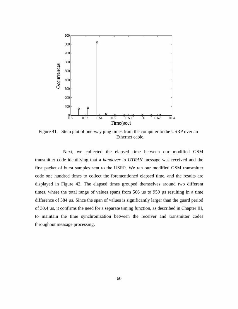
60
Figure 41. Stem plot of one-way ping times from the computer to the USRP over an Ethernet cable.
Next, we collected the elapsed time between our modified GSM
transmitter code identifying that a handover to UTRAN message was received and the
first packet of burst samples sent to the USRP. We ran our modified GSM transmitter
code one hundred times to collect the forementioned elapsed time, and the results are
displayed in Figure 42. The elapsed times grouped themselves around two different
times, where the total range of values spans from 566 µs to 950 µs resulting in a time
difference of 384 µs. Since the span of values is significantly larger than the guard period
of 30.4 µs, it confirms the need for a separate timing function, as described in Chapter III,
to maintain the time synchronization between the receiver and transmitter codes
throughout message processing.
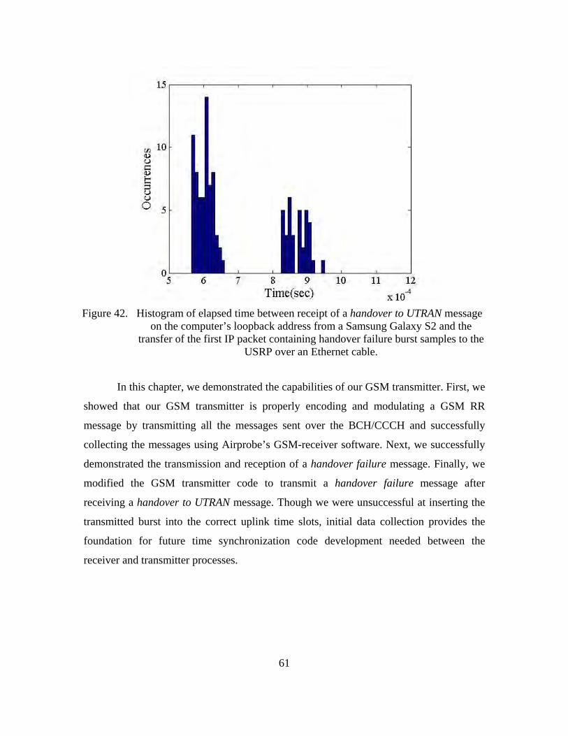
61
Figure 42. Histogram of elapsed time between receipt of a handover to UTRAN message on the computer’s loopback address from a Samsung Galaxy S2 and the
transfer of the first IP packet containing handover failure burst samples to the USRP over an Ethernet cable.
In this chapter, we demonstrated the capabilities of our GSM transmitter. First, we
showed that our GSM transmitter is properly encoding and modulating a GSM RR
message by transmitting all the messages sent over the BCH/CCCH and successfully
collecting the messages using Airprobe’s GSM-receiver software. Next, we successfully
demonstrated the transmission and reception of a handover failure message. Finally, we
modified the GSM transmitter code to transmit a handover failure message after
receiving a handover to UTRAN message. Though we were unsuccessful at inserting the
transmitted burst into the correct uplink time slots, initial data collection provides the
foundation for future time synchronization code development needed between the
receiver and transmitter processes.

62
THIS PAGE INTENTIONALLY LEFT BLANK
63
VI. CONCLUSIONS
The integration of GSM and UMTS networks into heterogeneous networks
provides malicious individuals the potential to deny an unsuspecting user the ability to
access the UMTS network thereby preventing them from taking advantage of the security
enhancements incorporated in the UMTS standards. The validation of this potential
vulnerability requires the creation of a device that can collect and decode a BTS BCH,
identify the transmission of a handover to UTRAN message, and transmit a handover
failure message in the correct time slots on the SDDCH uplink channel.
In this thesis, a GSM transmitter capable of transmitting a GSM RR message
using a SDR was proposed and experimentally validated. The GSM transmitter we
created in C++ code takes a LAPDm frame containing a RR message from data bits to
modulated in-phase and quadrature phase samples ready for transmission by a N210
USRP. The C++ code we developed first block encodes the LAPDm frame data bits, then
passes the encoded bits through a ½-rate convolutional encoder, interleaves the
convolved bits and maps the bits to a normal burst. Once formed into a normal burst, the
code we created diffentially encodes the burst, converts the burst bits to ( ) symbols,
convolves the symbols using a Gaussian pulse, resamples the in-phase and quadrature
phase samples in order to transmit the burst at the N210 USRP sampling rate and type
converts the samples from C++ type float to type short in preparation for sending the
samples to the N210 USRP.
After creating a GSM transmitter capable of transmission of a GSM RR message
in accordance with the 3GPP GSM standards, we developed and demonstarted a method
for collecting a handover to UTRAN message that triggers the GSM transmitter to send a
GSM handover failure message. A Samsung Galaxy S2 phone coupled with xgoldmon
code was configured to collect the handover to UTRAN message and send the message to
the computer’s loopback address. PCAP software functions were added to the GSM
transmitter code in order to listen to the computer’s loopback address and trigger the
transmission of a handover failure message.
64
Finally, the timing issues involved in collecting a handover to UTRAN message
by a Samsung Galaxy S2 phone and the transmission of a handover failure message by
the GSM transmitter we developed were investigated. We collected multiple runs of the
GSM transmitter code triggered by a handover to UTRAN message and found an
inconsistency in the code runtime, which confirmed the need for a timing function that
synchronizes the receiver and transmitter processes. Also, we found the maximum
transmission time for samples from the GSM transmitter to reach the N210 USRP, which
must be taken into account to ensure the samples are transmitted by the N210 USRP at
the correct time.
A. SIGNIFICANT CONTRIBUTIONS
Three significant contributions were made in this thesis. First, we proposed a
potential vulnerability in the handover process from GSM to UMTS caused by the weak
encryption algorithms employed by the GSM standards. The proposed vulnerability in the
handover process from GSM to UMTS extends the ideas presented in [4] and [5] by
giving additional motivation for GSM networks to employ stronger encryption and
provides the developers of the 3GPP standards a reason to re-evaluate how the GSM and
UMTS networks interoperate.
Second, we created open source GSM transmitter computer code that takes the
data bits from any GSM RR message encapsulated within a LAPDm frame as its input
and outputs a radio frequency burst in accordance with the 3GPP GSM standards. The
open source computer code we created to transmit any RR message provides the
transmitter functionality described in Chapter III, which is vital for the creation of a GSM
vulnerability testing device. Additionally, the code can be incorporated with any SDR
provided the SDR can obtain a sample rate of either 273.833 kHz or 400 kHz.
Finally, we reconfigured our open source GSM transmitter code to start
transmitting only after being triggered by a message sent from a Samsung Galaxy S2
phone to the host computer’s loopback address. The integration of the Samsung Galaxy
S2 phone with the GSM transmitter code provides a concept model of how a GSM
receiver and GSM transmitter could be integrated to create a GSM vulnerability testing
65
device. This type of integrated device is vital for testing the proposed vulnerability
discussed in Chapter III and the additional vulnerabilities described in [5] and [14].
B. FUTURE WORK
Even though we provided, in this thesis, an initial step toward the creation of a
GSM vulnerability testing device and gave the description of a potential vulnerability
involving handovers between GSM to UMTS networks, additional effort is required to
fully validate the vulnerability testing device and confirm the weakness of the handover
to UTRAN procedure.
In this thesis, we provided C++ computer code to transmit GSM RR message
bursts in accordance with the 3GPP GSM standards for encoding and modulation. The
primary limitation of the developed GSM transmitter is its inability to transmit the GSM
RR message in the correct SDCCH time slot on the uplink channel. The creation of
computer code to track the start of each burst on the downlink channel and use that
information to compute the wait time between the end of the last received message burst
on the SDCCH and the transmission start time for the first transmitted burst on the
SDCCH uplink channel is needed.
We also developed a methodology for reliably collecting the handover to UTRAN
message on the downlink channel and a technique for transmitting a handover failure
burst on the uplink channel. A limitation of our methodology stems from the device we
chose to use as our handover to UTRAN message receiver. We used the Samsung Galaxy
S2 as both our GSM receiver and as our trigger source for the handover failure
transmitter, which worked reliably in collecting a handover to UTRAN message sent by
the BTS to the phone but was incapable of collecting a handover to UTRAN message sent
to any other mobile device on the GSM network. A more robust GSM message receiver
and queuing source would be Airprobe’s GSM-receiver; however, as discussed in
Chapter V, source code changes are required in order for Airprobe’s GSM-receiver to
successfully decode a handover to UTRAN message. If Airprobe’s GSM-receiver code
were modified to identify the handover to UTRAN message, it would give us the ability to
66
trigger the GSM transmitter to transmit the handover failure burst after any mobile device
had started transitioning from GSM to UMTS.
Finally, we presented a potential vulnerability involving handovers between GSM
to UMTS networks, which draws from previously reported issues in [4], [5] and [14].
This potential vulnerability requires further testing and validation. We suggest
implementation of timing code within the triggered GSM transmitter code developed in
Chapter V in order to fully realize the handover vulnerability described in Chapter III.
67
APPENDIX A. XGOLDMON
This appendix contains the setup requirements and execution of the xgoldmon
code when using a Samsung Galaxy S2 phone. Prior to using the xgoldmon code, the
Samsung Galaxy S2 phone must first be configured to send all received messages from
the BTS over the USB to the computer. All the instructions for phone setup and
xgoldmon code execution originate from the readme file contained within the xgoldmon
source code [24].
The configuration of the Samsung Galaxy S2 is executed in the following three
steps. The first step involves changing the debugging settings on the phone. These
changes are accomplished by opening the phone’s call window and typing
*#*#197328640#*#* into the window, which causes the ServiceMode Main Menu screen
to open as shown in Figure 43. From the ServiceMode Main Menu, we choose option six,
common, in order to bring up the ServiceMode Common screen. Finally, we pick option
two, debug info, which opens the ServiceMode Debug Info screen where we change the
PCM logging and I2S logging to ON. After changing these two settings, we exit the
ServiceMode menu.
The second step requires the changing of the PhoneUtil settings. The PhoneUtil
menu is initialized by typing *#7284# into the call screen. Then change the UART and
USB settings in the PhoneUtil menu from PDA to Modem as shown in Figure 44. The
third step requires changing the Ramdump Mode setting in the SysDump menu, which is
initialized by typing *#9900# into the call screen. Then we change the Ramdump Mode
Enabled to High as shown in Figure 44.
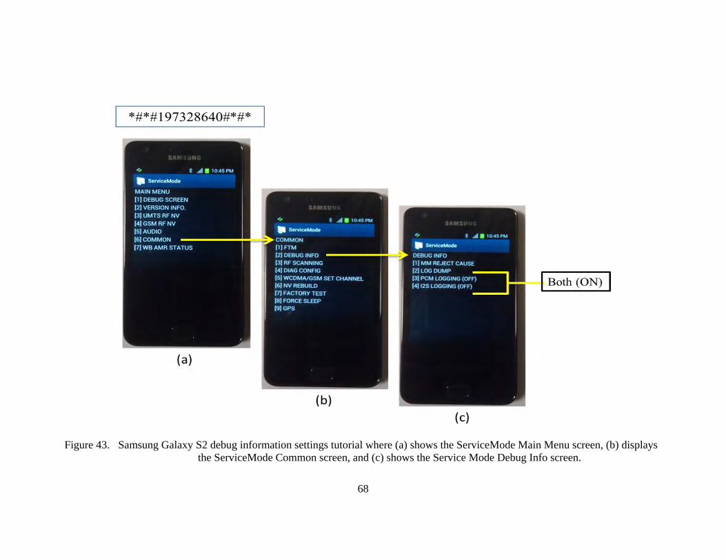
68
Figure 43. Samsung Galaxy S2 debug information settings tutorial where (a) shows the ServiceMode Main Menu screen, (b) displays the ServiceMode Common screen, and (c) shows the Service Mode Debug Info screen.
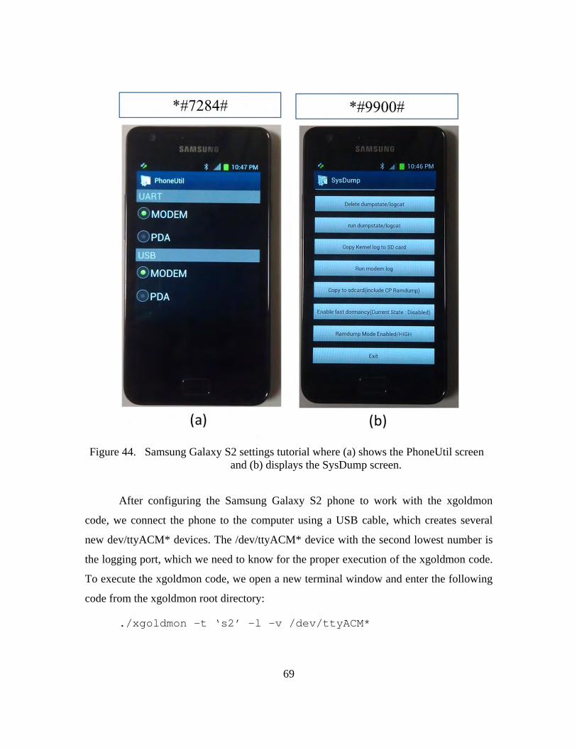
69
Figure 44. Samsung Galaxy S2 settings tutorial where (a) shows the PhoneUtil screen and (b) displays the SysDump screen.
After configuring the Samsung Galaxy S2 phone to work with the xgoldmon
code, we connect the phone to the computer using a USB cable, which creates several
new dev/ttyACM* devices. The /dev/ttyACM* device with the second lowest number is
the logging port, which we need to know for the proper execution of the xgoldmon code.
To execute the xgoldmon code, we open a new terminal window and enter the following
code from the xgoldmon root directory:
./xgoldmon –t ‘s2’ –l –v /dev/ttyACM*

70
where the asterick after ttyACM is the second lowest number of the new dev/ttyACM
devices created after plugging the phone into the computer. Finally, open Wireshark
using a new terminal window and start collecting on the loopback address.

71
APPENDIX B. BURST CREATOR AND GSM TRANSMITTER C++ CODE REPLICATING BTS
This appendix contains the code for transmitting the messages sent over a GSM
BTS BCH/CCCH. The first code is written in python and titled
GSM_message_hexadecimal_to_binary.py. This code is used to transition the
hexadecimal message values collected with the ASCOM TEMS software/hardware into
binary strings ready for encoding and burst mapping by the
GSM_Burst_Creator.cpp code. The GSM_Burst_Creator.cpp code takes the
binary output from the GSM_message_hexadecimal_to_binary.py code and
encodes, interleaves, and maps the bits onto a GSM normal burst with training sequence
number one. Finally, the GSM_BTS_Transmitter.cpp C++ code modulates, re-
samples, and transmits the GSM bursts created by the GSM_Burst_Creator.cpp
code.
Many of the functions in the GSM_Burst_Creator.cpp and the
GSM_BTS_Transmitter.cpp C++ codes were originally written in OpenBTS [1];
therefore, they require the following OpenBTS C++ source code files for proper
execution: sigProcLib.cpp, BitVector.cpp, GSMCommon.cpp, and
Timeval.cpp. The GSM_BTS_Transmitter.cpp code also requires the following
dependencies when using an Ubuntu Linux load: libboost-all-dev, libusb-1.0–0-dev,
python-cheetah, doxygen, and python-docutils. Finally, the
GSM_BTS_Transmitter.cpp code requires installation of Ettus UHD software.
A. GSM_MESSAGE_HEXADECIMAL_TO_BINARY.PY
#!/usr/bin/env python #---------------------------------------------------------------------- # Name: GSM_message_hexadecimal_to_binary # Purpose: Convert a list of hexadecimal to a list of binary values # Author: Carson McAbee # Created: 21 JUL 2013 #---------------------------------------------------------------------- #
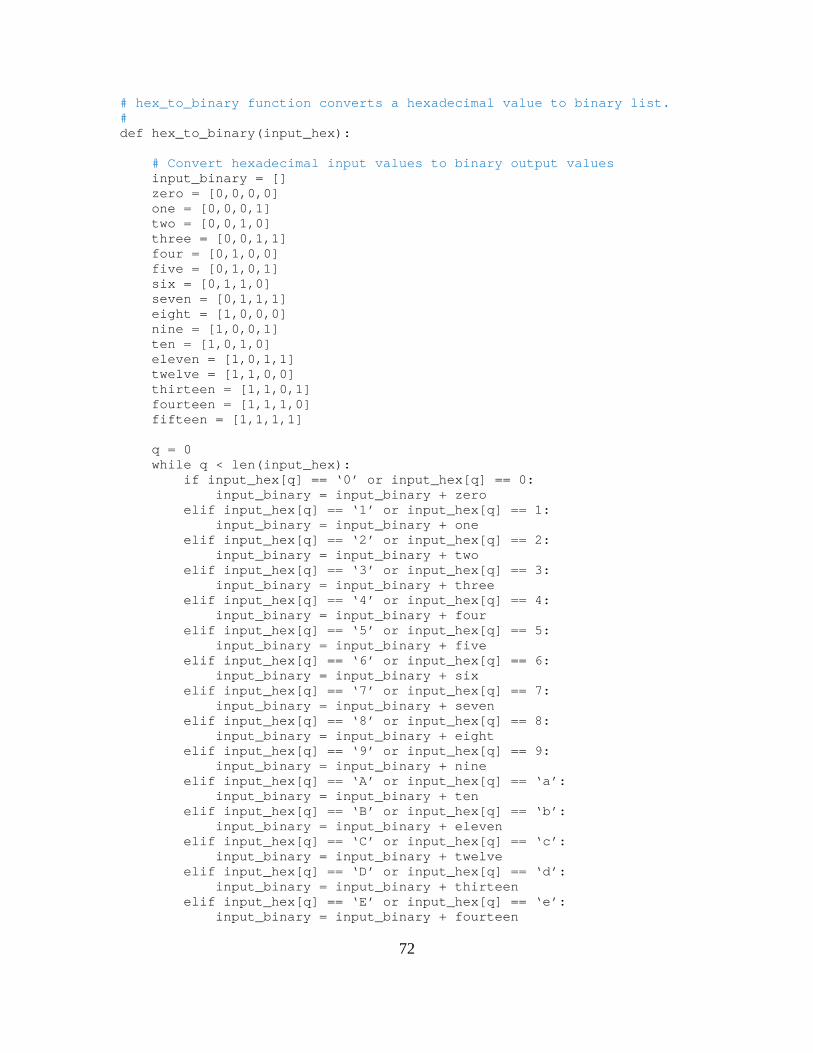
72
# hex_to_binary function converts a hexadecimal value to binary list. # def hex_to_binary(input_hex): # Convert hexadecimal input values to binary output values input_binary = [] zero = [0,0,0,0] one = [0,0,0,1] two = [0,0,1,0] three = [0,0,1,1] four = [0,1,0,0] five = [0,1,0,1] six = [0,1,1,0] seven = [0,1,1,1] eight = [1,0,0,0] nine = [1,0,0,1] ten = [1,0,1,0] eleven = [1,0,1,1] twelve = [1,1,0,0] thirteen = [1,1,0,1] fourteen = [1,1,1,0] fifteen = [1,1,1,1] q = 0 while q < len(input_hex): if input_hex[q] == ‘0’ or input_hex[q] == 0: input_binary = input_binary + zero elif input_hex[q] == ‘1’ or input_hex[q] == 1: input_binary = input_binary + one elif input_hex[q] == ‘2’ or input_hex[q] == 2: input_binary = input_binary + two elif input_hex[q] == ‘3’ or input_hex[q] == 3: input_binary = input_binary + three elif input_hex[q] == ‘4’ or input_hex[q] == 4: input_binary = input_binary + four elif input_hex[q] == ‘5’ or input_hex[q] == 5: input_binary = input_binary + five elif input_hex[q] == ‘6’ or input_hex[q] == 6: input_binary = input_binary + six elif input_hex[q] == ‘7’ or input_hex[q] == 7: input_binary = input_binary + seven elif input_hex[q] == ‘8’ or input_hex[q] == 8: input_binary = input_binary + eight elif input_hex[q] == ‘9’ or input_hex[q] == 9: input_binary = input_binary + nine elif input_hex[q] == ‘A’ or input_hex[q] == ‘a’: input_binary = input_binary + ten elif input_hex[q] == ‘B’ or input_hex[q] == ‘b’: input_binary = input_binary + eleven elif input_hex[q] == ‘C’ or input_hex[q] == ‘c’: input_binary = input_binary + twelve elif input_hex[q] == ‘D’ or input_hex[q] == ‘d’: input_binary = input_binary + thirteen elif input_hex[q] == ‘E’ or input_hex[q] == ‘e’: input_binary = input_binary + fourteen
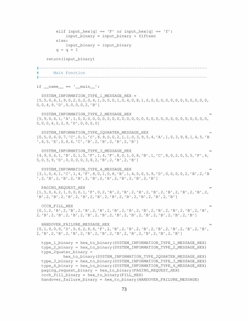
73
elif input_hex[q] == ‘F’ or input_hex[q] == ‘f’: input_binary = input_binary + fifteen else: input_binary = input_binary q = q + 1 return(input_binary) #--------------------------------------------------------------------- # Main Function #--------------------------------------------------------------------- if __name__ == ‘__main__’: SYSTEM_INFORMATION_TYPE_1_MESSAGE_HEX = [5,5,0,6,1,9,0,2,0,2,0,4,1,0,0,0,1,0,4,0,8,1,0,0,0,0,0,0,0,0,0,0,0,0,0,0,0,4,9,’D’,0,0,0,0,2,’B’] SYSTEM_INFORMATION_TYPE_2_MESSAGE_HEX = [5,9,0,6,1,’A’,1,0,0,0,0,0,0,0,0,0,0,0,0,0,0,0,0,0,0,0,0,0,0,0,0,0,0,0,0,0,0,4,0,2,9,’D’,0,0,0,0] SYSTEM_INFORMATION_TYPE_2QUARTER_MESSAGE_HEX = [0,5,0,6,0,7,’C’,0,1,’C’,8,9,0,0,2,1,1,0,3,9,5,4,’A’,1,0,3,9,8,1,4,5,’B’,6,5,’E’,0,8,6,’C’,’B’,2,’B’,2,’B’,2,’B’] SYSTEM_INFORMATION_TYPE_3_MESSAGE_HEX = [4,9,0,6,1,’B’,0,1,5,’F’,1,4,’F’,8,0,1,0,8,’B’,1,’C’,8,0,2,0,5,5,’F’,4,5,0,5,9,’D’,0,0,0,0,3,8,2,’B’,2,’B’,2,’B’] SYSTEM_INFORMATION_TYPE_4_MESSAGE_HEX = [3,1,0,6,1,’C’,1,4,’F’,8,0,1,0,8,’B’,1,4,5,0,5,9,’D’,0,0,0,0,2,’B’,2,’B’,2,’B’,2,’B’,2,’B’,2,’B’,2,’B’,2,’B’,2,’B’,2,’B’] PAGING_REQUEST_HEX = [1,5,0,6,2,1,0,0,0,1,’F’,0,2,’B’,2,’B’,2,’B’,2,’B’,2,’B’,2,’B’,2,’B’,2,’B’,2,’B’,2,’B’,2,’B’,2,’B’,2,’B’,2,’B’,2,’B’,2,’B’,2,’B’] CCCH_FILL_HEX = [0,1,2,’B’,2,’B’,2,’B’,2,’B’,2,’B’,2,’B’,2,’B’,2,’B’,2,’B’,2,’B’,2,’B’,2,’B’,2,’B’,2,’B’,2,’B’,2,’B’,2,’B’,2,’B’,2,’B’,2,’B’,2,’B’,2,’B’] HANDOVER_FAILURE_MESSAGE_HEX = [0,1,0,0,0,’D’,0,6,2,8,6,’F’,2,’B’,2,’B’,2,’B’,2,’B’,2,’B’,2,’B’,2,’B’,2,’B’,2,’B’,2,’B’,2,’B’,2,’B’,2,’B’,2,’B’,2,’B’,2,’B’,2,’B’] type_1_binary = hex_to_binary(SYSTEM_INFORMATION_TYPE_1_MESSAGE_HEX) type_2_binary = hex_to_binary(SYSTEM_INFORMATION_TYPE_2_MESSAGE_HEX) type_2quater_binary = hex_to_binary(SYSTEM_INFORMATION_TYPE_2QUARTER_MESSAGE_HEX) type_3_binary = hex_to_binary(SYSTEM_INFORMATION_TYPE_3_MESSAGE_HEX) type_4_binary = hex_to_binary(SYSTEM_INFORMATION_TYPE_4_MESSAGE_HEX) paging_request_binary = hex_to_binary(PAGING_REQUEST_HEX) ccch_fill_binary = hex_to_binary(FILL_HEX) handover_failure_binary = hex_to_binary(HANDOVER_FAILURE_MESSAGE)
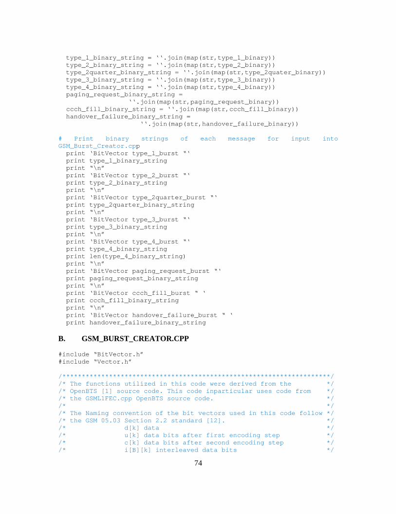
74
type_1_binary_string = ‘‘.join(map(str,type_1_binary)) type_2_binary_string = ‘‘.join(map(str,type_2_binary)) type_2quarter_binary_string = ‘‘.join(map(str,type_2quater_binary)) type_3_binary_string = ‘‘.join(map(str,type_3_binary)) type_4_binary_string = ‘‘.join(map(str,type_4_binary)) paging_request_binary_string = ‘‘.join(map(str,paging_request_binary)) ccch_fill_binary_string = ‘‘.join(map(str,ccch_fill_binary)) handover_failure_binary_string = ‘‘.join(map(str,handover_failure_binary)) # Print binary strings of each message for input into GSM_Burst_Creator.cpp print ‘BitVector type_1_burst “‘ print type_1_binary_string print “\n” print ‘BitVector type_2_burst “‘ print type_2_binary_string print “\n” print ‘BitVector type_2quarter_burst “‘ print type_2quarter_binary_string print “\n” print ‘BitVector type_3_burst “‘ print type_3_binary_string print “\n” print ‘BitVector type_4_burst “‘ print type_4_binary_string print len(type_4_binary_string) print “\n” print ‘BitVector paging_request_burst “‘ print paging_request_binary_string print “\n” print ‘BitVector ccch_fill_burst “ ‘ print ccch_fill_binary_string print “\n” print ‘BitVector handover_failure_burst “ ‘ print handover_failure_binary_string
B. GSM_BURST_CREATOR.CPP
#include “BitVector.h” #include “Vector.h” /*********************************************************************/ /* The functions utilized in this code were derived from the */ /* OpenBTS [1] source code. This code inparticular uses code from */ /* the GSML1FEC.cpp OpenBTS source code. */ /* */ /* The Naming convention of the bit vectors used in this code follow */ /* the GSM 05.03 Section 2.2 standard [12]. */ /* d[k] data */ /* u[k] data bits after first encoding step */ /* c[k] data bits after second encoding step */ /* i[B][k] interleaved data bits */
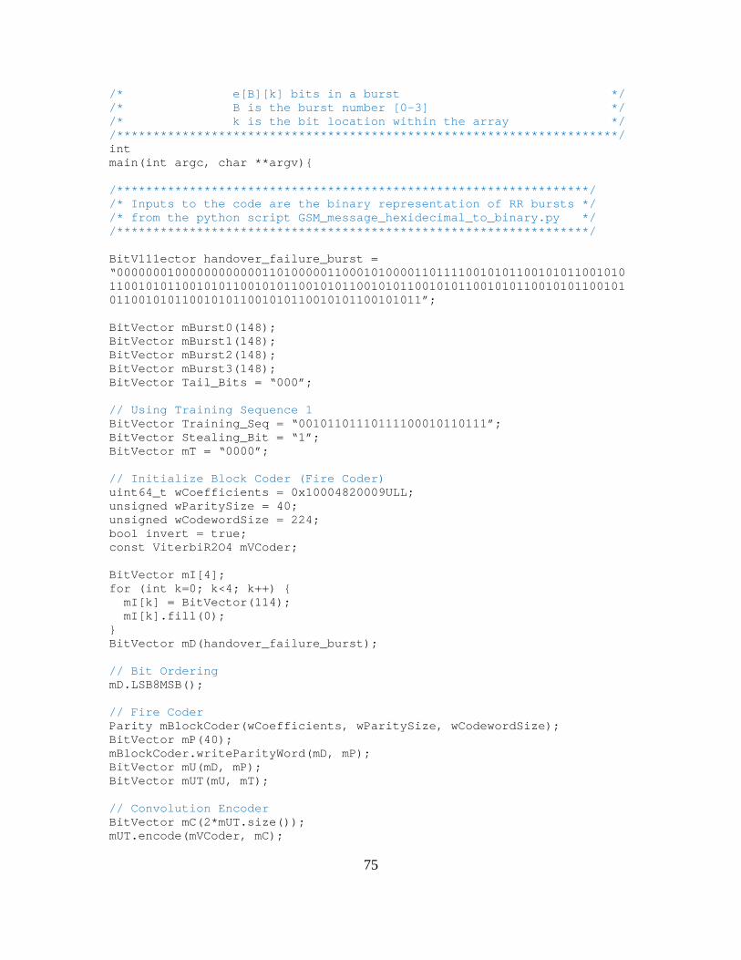
75
/* e[B][k] bits in a burst */ /* B is the burst number [0–3] */ /* k is the bit location within the array */ /*********************************************************************/ int main(int argc, char **argv){ /*****************************************************************/ /* Inputs to the code are the binary representation of RR bursts */ /* from the python script GSM_message_hexidecimal_to_binary.py */ /*****************************************************************/ BitV111ector handover_failure_burst = “0000000100000000000011010000011000101000011011110010101100101011001010110010101100101011001010110010101100101011001010110010101100101011001010110010101100101011001010110010101100101011”; BitVector mBurst0(148); BitVector mBurst1(148); BitVector mBurst2(148); BitVector mBurst3(148); BitVector Tail_Bits = “000”; // Using Training Sequence 1 BitVector Training_Seq = “00101101110111100010110111”; BitVector Stealing_Bit = “1”; BitVector mT = “0000”; // Initialize Block Coder (Fire Coder) uint64_t wCoefficients = 0x10004820009ULL; unsigned wParitySize = 40; unsigned wCodewordSize = 224; bool invert = true; const ViterbiR2O4 mVCoder; BitVector mI[4]; for (int k=0; k<4; k++) { mI[k] = BitVector(114); mI[k].fill(0); } BitVector mD(handover_failure_burst); // Bit Ordering mD.LSB8MSB(); // Fire Coder Parity mBlockCoder(wCoefficients, wParitySize, wCodewordSize); BitVector mP(40); mBlockCoder.writeParityWord(mD, mP); BitVector mU(mD, mP); BitVector mUT(mU, mT); // Convolution Encoder BitVector mC(2*mUT.size()); mUT.encode(mVCoder, mC);

76
// Interleaver for (int k=0; k<456; k++) { int B = k%4; int j = 2*((49*k) % 57) + ((k%8)/4); mI[B][j] = mC[k]; } // Burst Mapping Tail_Bits.copyToSegment(mBurst0,0); mI[0].segment(0,57).copyToSegment(mBurst0,3); mI[0].segment(57,57).copyToSegment(mBurst0,88); Training_Seq.copyToSegment(mBurst0,61); Stealing_Bit.copyToSegment(mBurst0,60); Tail_Bits.copyToSegment(mBurst0,145); Tail_Bits.copyToSegment(mBurst1,0); mI[1].segment(0,57).copyToSegment(mBurst1,3); mI[1].segment(57,57).copyToSegment(mBurst1,88); Training_Seq.copyToSegment(mBurst1,61); Stealing_Bit.copyToSegment(mBurst1,60); Tail_Bits.copyToSegment(mBurst1,145); Tail_Bits.copyToSegment(mBurst2,0); mI[2].segment(0,57).copyToSegment(mBurst2,3); mI[2].segment(57,57).copyToSegment(mBurst2,88); Training_Seq.copyToSegment(mBurst2,61); Stealing_Bit.copyToSegment(mBurst2,60); Tail_Bits.copyToSegment(mBurst2,145); Tail_Bits.copyToSegment(mBurst3,0); mI[3].segment(0,57).copyToSegment(mBurst3,3); mI[3].segment(57,57).copyToSegment(mBurst3,88); Training_Seq.copyToSegment(mBurst3,61); Stealing_Bit.copyToSegment(mBurst3,60); Tail_Bits.copyToSegment(mBurst3,145); // Prints out bursts for later input into GSM transmitter code std::cout << “BitVector(“ << mBurst0 << “),” << “// Handover_Failure_burst0” << std::endl; std::cout << “BitVector(“ << mBurst1 << “),” << “// Handover_Failure_burst1” << std::endl; std::cout << “BitVector(“ << mBurst2 << “),” << “// Handover_Failure_burst2” << std::endl; std::cout << “BitVector(“ << mBurst3 << “),” << “// Handover_Failure_burst3” << std::endl; } // end main loop
C. GSM_BTS_TRANSMITTER.CPP
#include <uhd/utils/thread_priority.hpp>
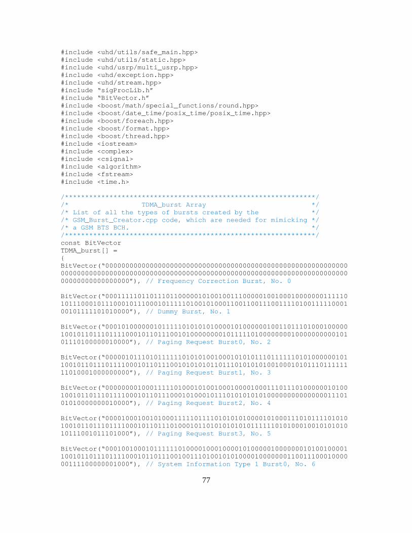
77
#include <uhd/utils/safe_main.hpp> #include <uhd/utils/static.hpp> #include <uhd/usrp/multi_usrp.hpp> #include <uhd/exception.hpp> #include <uhd/stream.hpp> #include “sigProcLib.h” #include “BitVector.h” #include <boost/math/special_functions/round.hpp> #include <boost/date_time/posix_time/posix_time.hpp> #include <boost/foreach.hpp> #include <boost/format.hpp> #include <boost/thread.hpp> #include <iostream> #include <complex> #include <csignal> #include <algorithm> #include <fstream> #include <time.h> /**************************************************************/ /* TDMA_burst Array */ /* List of all the types of bursts created by the */ /* GSM_Burst_Creator.cpp code, which are needed for mimicking */ /* a GSM BTS BCH. */ /**************************************************************/ const BitVector TDMA_burst[] = { BitVector(“0000000000000000000000000000000000000000000000000000000000000000000000000000000000000000000000000000000000000000000000000000000000000000000000000000”), // Frequency Correction Burst, No. 0 BitVector(“0001111101101110110000010100100111000001001000100000001111101011100010111000101110001011111010010100011001100111001111010011111000100101111101010000”), // Dummy Burst, No. 1 BitVector(“0001010000001011111010101010000101000000100110111010001000001001011011101111000101101110010100000000101111101000000001000000000010101110100000010000”), // Paging Request Burst0, No. 2 BitVector(“0000010111010111111010101001000101010111011111101010000001011001011011101111000101101110010101010110111010101010010001010111011111111010001000000000”), // Paging Request Burst1, No. 3 BitVector(“0000000010001111101000101001000100001000111011101000000101001001011011101111000101101110001010001011101010101010000000000000001110101010000000010000”), // Paging Request Burst2, No. 4 BitVector(“0000100010010100011111011110101010100001010001110101111010101001011011101111000101101110100010110101010101011111101010001001010101010111001011101000”), // Paging Request Burst3, No. 5 BitVector(“0001001000101111110100001000100001010000010000000101001000011001011011101111000101101110010011101001010100001000000011001110001000000111100000001000”), // System Information Type 1 Burst0, No. 6
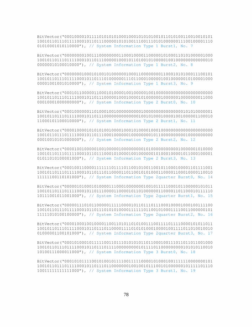
78
BitVector(“0001000010111101010101000100010101010010110101001100100101011001011011101111000101101110000010101001110011101010000001110010000111001010001010110000”), // System Information Type 1 Burst1, No. 7 BitVector(“0000000010011100000000110001000011000001010001101010000010001001011011101111000101101110000010001011010010100000100100000000000001000000010100010000”), // System Information Type 1 Burst2, No. 8 BitVector(“0000000100010100101000000100011000000001100010101000111001011001011011101111000101101110100000011101100010000010010000001010000100000001001001010000”), // System Information Type 1 Burst3, No. 9 BitVector(“0001011000001100010100001001000001001000000000000000000000001001011011101111000101101110000010001000010100000010000001000000001100000010001000000000”), // System Information Type 2 Burst0, No. 10 BitVector(“0001000000110100010010000000000100000000000000001010100000011001011011101111000101101110000000000000010010100010000100100000110001011000101100010000”), // System Information Type 2 Burst1, No. 11 BitVector(“0000100001010101001000010001010000100010000000000000000000001001011011101111000101101110001000000100000000101100000000001000000000000010010101000000”), // System Information Type 2 Burst2, No. 12 BitVector(“0000100100000100100000100000000010100000000000100000010100001001011011101111000101101110001010000100100000010100010000101100010000101011010100001000”), // System Information Type 2 Burst3, No. 13 BitVector(“0001001100001111111011110110010100110010110001000011011110011001011011101111000101101110110000110110010101000110000110001000011001011111100110101000”), // System Information Type 2quarter Burst0, No. 14 BitVector(“0000010100010100001110001000000010010111110001011000001010111001011011101111000101101110000110000101101000000110000110110001011111010111001011001000”), // System Information Type 2quarter Burst1, No. 15 BitVector(“0000011101011000001111100001011011101110001000010001001111001001011011101111000101101110101010000111111011001010001111001100000010111111010100100000”), // System Information Type 2quarter Burst2, No. 16 BitVector(“0000100010010000110011010110101001110011110111100001010110111001011011101111000101101110110000111101010100010000100111101101001001001000001100101000”), // System Information Type 2quarter Burst3, No. 17 BitVector(“0001010001011111001101110101010110110001001110110110110010001001011011101111000101101110111100000000010111101100000000010101011001010100111000011000”), // System Information Type 3 Burst0, No. 18 BitVector(“0001010111100101001011110011111000010100010011111100000001011001011011101111000101101110110000000100100101110010100000010111110111010011111111111000”), // System Information Type 3 Burst1, No. 19
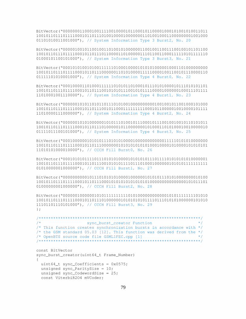
79
BitVector(“0000000110001001111001000010110001011000010001010010100110111001011011101111000101101110100100001000000011010010001100000000100100001101010011001000”), // System Information Type 3 Burst2, No. 20 BitVector(“0000010010110010011010010100000011001001100111001001011011001001011011101111000101101110110000110100000111011001100011111010111111001000101100101000”), // System Information Type 3 Burst3, No. 21 BitVector(“0001010100101001111110100010000101010100000100011010000000001001011011101111000101101110000001101010000111110000100110010111000011001111101010001000”), // System Information Type 4 Burst0, No. 22 BitVector(“0001000011010001111110101011010001011101010000101110101011011001011011101111000101101110010101011100101011110000100000010001110111111010001001110000”), // System Information Type 4 Burst1, No. 23 BitVector(“0000001010110101101110101001000000000010010010110010001010001001011011101111000101101110010110001111111110001011000001001000010111111010000111000000”), // System Information Type 4 Burst2, No. 24 BitVector(“0000001010100000010101110100101110001011100100100101101010111001011011101111000101101110100000101100000001010001101010001001000001001111011100101000”), // System Information Type 4 Burst3, No. 25 BitVector(“0001000000101010111010101000010000000000001111101010100000001001011011101111000101101110000000101010101010100010000101000010101010111010101000010000”), // CCCH Fill Burst0, No. 26 BitVector(“0001010101111011101010100001010101011101111010101010100000011001011011101111000101101110010101011110111010001000000101010111111111101010000001000000”), // CCCH Fill Burst1, No. 27 BitVector(“0000000000101110101010100001000000101010111010100000000101001001011011101111000101101110001010101010101010100000000000000010101110101000000001000000”), // CCCH Fill Burst2, No. 28 BitVector(“0000001000000101011111111110101000000000000101011111111010101001011011101111000101101110100000010101010101111011101010100000010101011101101110101000”), // CCCH Fill Burst3, No. 29 }; /*******************************************************************/ /* sync_burst_creator Function */ /* This function creates synchronization bursts in accordance with */ /* the GSM standard 05.03 [12]. This function was derived from the */ /* OpenBTS source code file GSML1FEC.cpp [1] */ /*******************************************************************/ const BitVector sync_burst_creator(uint64_t Frame_Number) { uint64_t sync_Coefficients = 0x0575; unsigned sync_ParitySize = 10; unsigned sync_CodewordSize = 25; const ViterbiR2O4 mVCoder;
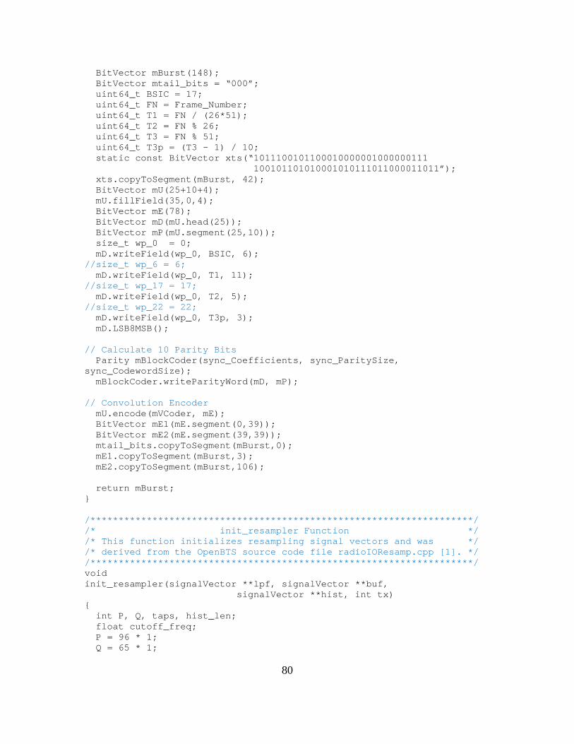
80
BitVector mBurst(148); BitVector mtail_bits = “000”; uint64_t BSIC = 17; uint64_t FN = Frame_Number; uint64_t T1 = FN / (26*51); uint64_t T2 = FN % 26; uint64_t T3 = FN % 51; uint64_t T3p = (T3 - 1) / 10; static const BitVector xts(“1011100101100010000001000000111 100101101010001010111011000011011”); xts.copyToSegment(mBurst, 42); BitVector mU(25+10+4); mU.fillField(35,0,4); BitVector mE(78); BitVector mD(mU.head(25)); BitVector mP(mU.segment(25,10)); size_t wp_0 = 0; mD.writeField(wp_0, BSIC, 6); //size_t wp_6 = 6; mD.writeField(wp_0, T1, 11); //size_t wp_17 = 17; mD.writeField(wp_0, T2, 5); //size_t wp_22 = 22; mD.writeField(wp_0, T3p, 3); mD.LSB8MSB(); // Calculate 10 Parity Bits Parity mBlockCoder(sync_Coefficients, sync_ParitySize, sync_CodewordSize); mBlockCoder.writeParityWord(mD, mP); // Convolution Encoder mU.encode(mVCoder, mE); BitVector mE1(mE.segment(0,39)); BitVector mE2(mE.segment(39,39)); mtail_bits.copyToSegment(mBurst,0); mE1.copyToSegment(mBurst,3); mE2.copyToSegment(mBurst,106); return mBurst; } /********************************************************************/ /* init_resampler Function */ /* This function initializes resampling signal vectors and was */ /* derived from the OpenBTS source code file radioIOResamp.cpp [1]. */ /********************************************************************/ void init_resampler(signalVector **lpf, signalVector **buf, signalVector **hist, int tx) { int P, Q, taps, hist_len; float cutoff_freq; P = 96 * 1; Q = 65 * 1;
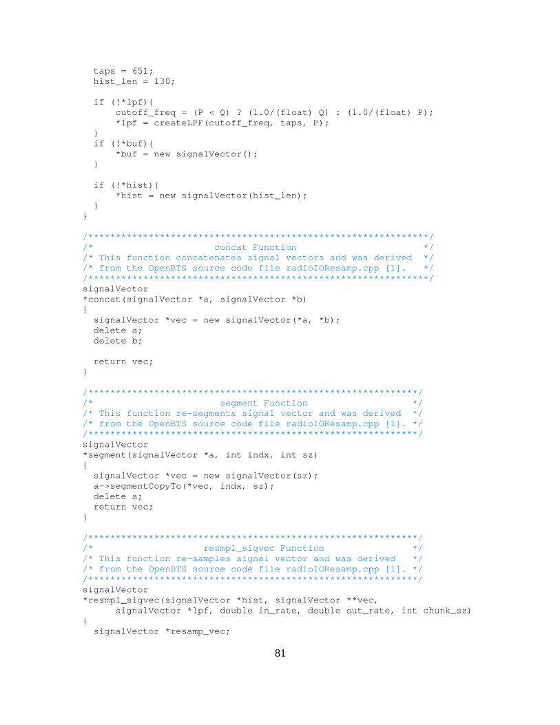
81
taps = 651; hist_len = 130; if (!*lpf){ cutoff_freq = (P < Q) ? (1.0/(float) Q) : (1.0/(float) P); *lpf = createLPF(cutoff_freq, taps, P); } if (!*buf){ *buf = new signalVector(); } if (!*hist){ *hist = new signalVector(hist_len); } } /**************************************************************/ /* concat Function */ /* This function concatenates signal vectors and was derived */ /* from the OpenBTS source code file radioIOResamp.cpp [1]. */ /**************************************************************/ signalVector *concat(signalVector *a, signalVector *b) { signalVector *vec = new signalVector(*a, *b); delete a; delete b; return vec; } /************************************************************/ /* segment Function */ /* This function re-segments signal vector and was derived */ /* from the OpenBTS source code file radioIOResamp.cpp [1]. */ /************************************************************/ signalVector *segment(signalVector *a, int indx, int sz) { signalVector *vec = new signalVector(sz); a->segmentCopyTo(*vec, indx, sz); delete a; return vec; } /************************************************************/ /* resmpl_sigvec Function */ /* This function re-samples signal vector and was derived */ /* from the OpenBTS source code file radioIOResamp.cpp [1]. */ /************************************************************/ signalVector *resmpl_sigvec(signalVector *hist, signalVector **vec, signalVector *lpf, double in_rate, double out_rate, int chunk_sz) { signalVector *resamp_vec;
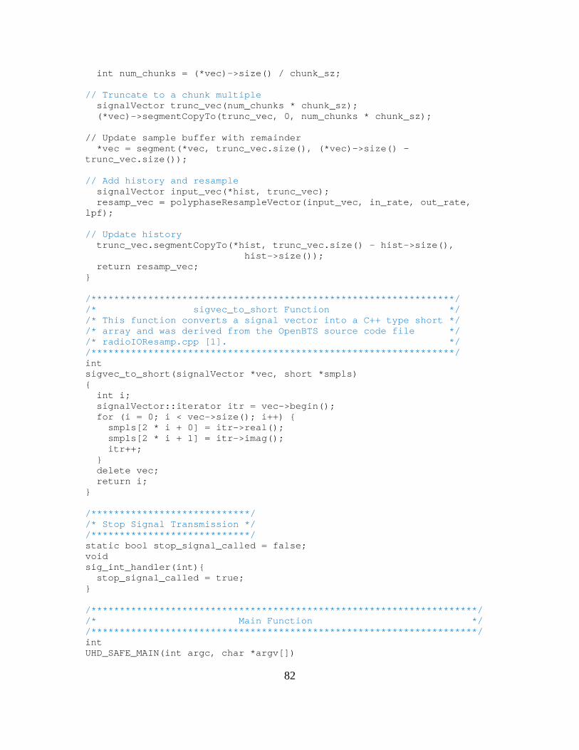
82
int num_chunks = (*vec)->size() / chunk_sz; // Truncate to a chunk multiple signalVector trunc_vec(num_chunks * chunk_sz); (*vec)->segmentCopyTo(trunc_vec, 0, num_chunks * chunk_sz); // Update sample buffer with remainder *vec = segment(*vec, trunc_vec.size(), (*vec)->size() - trunc_vec.size()); // Add history and resample signalVector input_vec(*hist, trunc_vec); resamp_vec = polyphaseResampleVector(input_vec, in_rate, out_rate, lpf); // Update history trunc_vec.segmentCopyTo(*hist, trunc_vec.size() - hist->size(), hist->size()); return resamp_vec; } /****************************************************************/ /* sigvec_to_short Function */ /* This function converts a signal vector into a C++ type short */ /* array and was derived from the OpenBTS source code file */ /* radioIOResamp.cpp [1]. */ /****************************************************************/ int sigvec_to_short(signalVector *vec, short *smpls) { int i; signalVector::iterator itr = vec->begin(); for (i = 0; i < vec->size(); i++) { smpls[2 * i + 0] = itr->real(); smpls[2 * i + 1] = itr->imag(); itr++; } delete vec; return i; } /****************************/ /* Stop Signal Transmission */ /****************************/ static bool stop_signal_called = false; void sig_int_handler(int){ stop_signal_called = true; } /********************************************************************/ /* Main Function */ /********************************************************************/ int UHD_SAFE_MAIN(int argc, char *argv[])

83
{ uhd::set_thread_priority_safe(); /************************/ /* Initialize Variables */ /************************/ bool repeat = true; std::string args = ““; double tx_sample_rate = 400e3; double tx_freq = 938400000; //ARFCN 17 downlink frequency float tx_gain = 1; double tx_bandwidth = 200000; std::string ant = “TX/RX”; int samplesPerSymbol = 1; int numARFCN = 1; double fullScaleInputValue = (32000)*(0.3); int mOversamplingRate = numARFCN/2 + numARFCN; // Initialize Signal Processing Library sigProcLibSetup(samplesPerSymbol); // Create GSM Pulse signalVector *gsmPulse = generateGSMPulse(2,1); // Initialize vector which holds re-sampler’s low pass filter signalVector *tx_lpf = 0; // Initialize vector which holds re-sampler’s history vector signalVector *tx_hist = 0; // Initialize vector which holds re-sampler’s input buffer signalVector *tx_vec = 0; // Initialize re-sampler init_resampler(&tx_lpf, &tx_vec, &tx_hist, true); /*******************/ /* Initialize USRP */ /*******************/ uhd::usrp::multi_usrp::sptr usrp; usrp = uhd::usrp::multi_usrp::make(args); // Create transmit streamer uhd::stream_args_t stream_args; stream_args.cpu_format = “sc16”; uhd::tx_streamer::sptr tx_stream = usrp->get_tx_stream(stream_args); // Set the transmit sample rate (Hz) usrp->set_tx_rate(tx_sample_rate); double actual_tx_rate = usrp->get_tx_rate(); // Set the transmit gain (dB) usrp->set_tx_gain(tx_gain); // Set the transmit frequency (Hz)
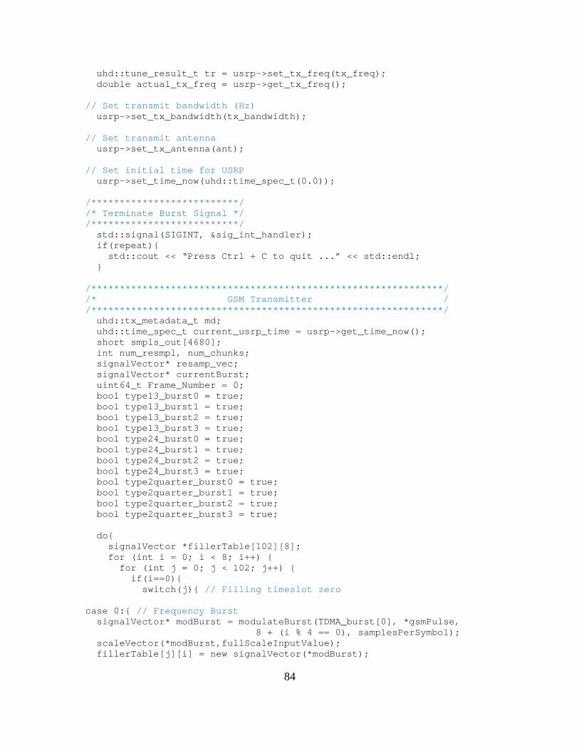
84
uhd::tune_result_t tr = usrp->set_tx_freq(tx_freq); double actual_tx_freq = usrp->get_tx_freq(); // Set transmit bandwidth (Hz) usrp->set_tx_bandwidth(tx_bandwidth); // Set transmit antenna usrp->set_tx_antenna(ant); // Set initial time for USRP usrp->set_time_now(uhd::time_spec_t(0.0)); /**************************/ /* Terminate Burst Signal */ /**************************/ std::signal(SIGINT, &sig_int_handler); if(repeat){ std::cout << “Press Ctrl + C to quit ...” << std::endl; } /**************************************************************/ /* GSM Transmitter / /**************************************************************/ uhd::tx_metadata_t md; uhd::time_spec_t current_usrp_time = usrp->get_time_now(); short smpls_out[4680]; int num_resmpl, num_chunks; signalVector* resamp_vec; signalVector* currentBurst; uint64_t Frame_Number = 0; bool type13_burst0 = true; bool type13_burst1 = true; bool type13_burst2 = true; bool type13_burst3 = true; bool type24_burst0 = true; bool type24_burst1 = true; bool type24_burst2 = true; bool type24_burst3 = true; bool type2quarter_burst0 = true; bool type2quarter_burst1 = true; bool type2quarter_burst2 = true; bool type2quarter_burst3 = true; do{ signalVector *fillerTable[102][8]; for (int i = 0; i < 8; i++) { for (int j = 0; j < 102; j++) { if(i==0){ switch(j){ // Filling timeslot zero case 0:{ // Frequency Burst signalVector* modBurst = modulateBurst(TDMA_burst[0], *gsmPulse, 8 + (i % 4 == 0), samplesPerSymbol); scaleVector(*modBurst,fullScaleInputValue); fillerTable[j][i] = new signalVector(*modBurst);
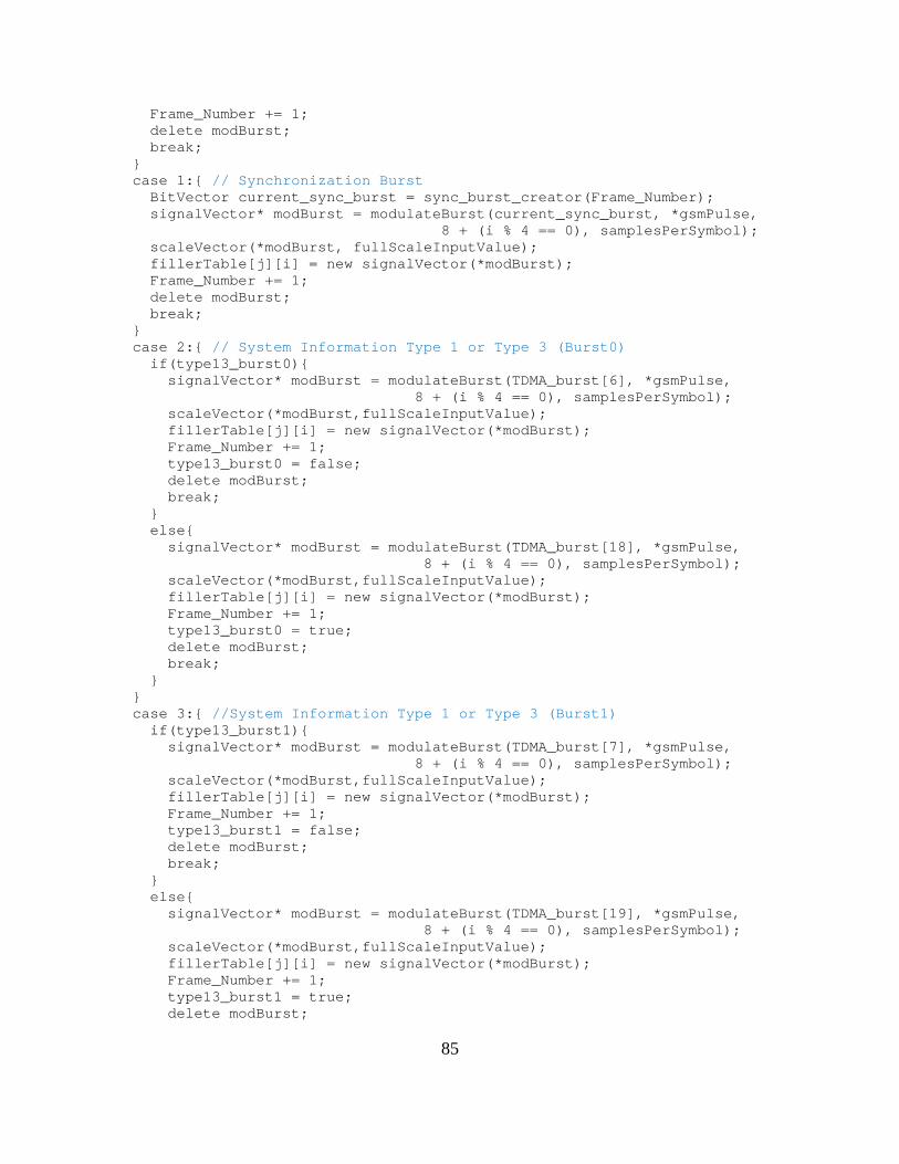
85
Frame_Number += 1; delete modBurst; break; } case 1:{ // Synchronization Burst BitVector current_sync_burst = sync_burst_creator(Frame_Number); signalVector* modBurst = modulateBurst(current_sync_burst, *gsmPulse, 8 + (i % 4 == 0), samplesPerSymbol); scaleVector(*modBurst, fullScaleInputValue); fillerTable[j][i] = new signalVector(*modBurst); Frame_Number += 1; delete modBurst; break; } case 2:{ // System Information Type 1 or Type 3 (Burst0) if(type13_burst0){ signalVector* modBurst = modulateBurst(TDMA_burst[6], *gsmPulse, 8 + (i % 4 == 0), samplesPerSymbol); scaleVector(*modBurst,fullScaleInputValue); fillerTable[j][i] = new signalVector(*modBurst); Frame_Number += 1; type13_burst0 = false; delete modBurst; break; } else{ signalVector* modBurst = modulateBurst(TDMA_burst[18], *gsmPulse, 8 + (i % 4 == 0), samplesPerSymbol); scaleVector(*modBurst,fullScaleInputValue); fillerTable[j][i] = new signalVector(*modBurst); Frame_Number += 1; type13_burst0 = true; delete modBurst; break; } } case 3:{ //System Information Type 1 or Type 3 (Burst1) if(type13_burst1){ signalVector* modBurst = modulateBurst(TDMA_burst[7], *gsmPulse, 8 + (i % 4 == 0), samplesPerSymbol); scaleVector(*modBurst,fullScaleInputValue); fillerTable[j][i] = new signalVector(*modBurst); Frame_Number += 1; type13_burst1 = false; delete modBurst; break; } else{ signalVector* modBurst = modulateBurst(TDMA_burst[19], *gsmPulse, 8 + (i % 4 == 0), samplesPerSymbol); scaleVector(*modBurst,fullScaleInputValue); fillerTable[j][i] = new signalVector(*modBurst); Frame_Number += 1; type13_burst1 = true; delete modBurst;
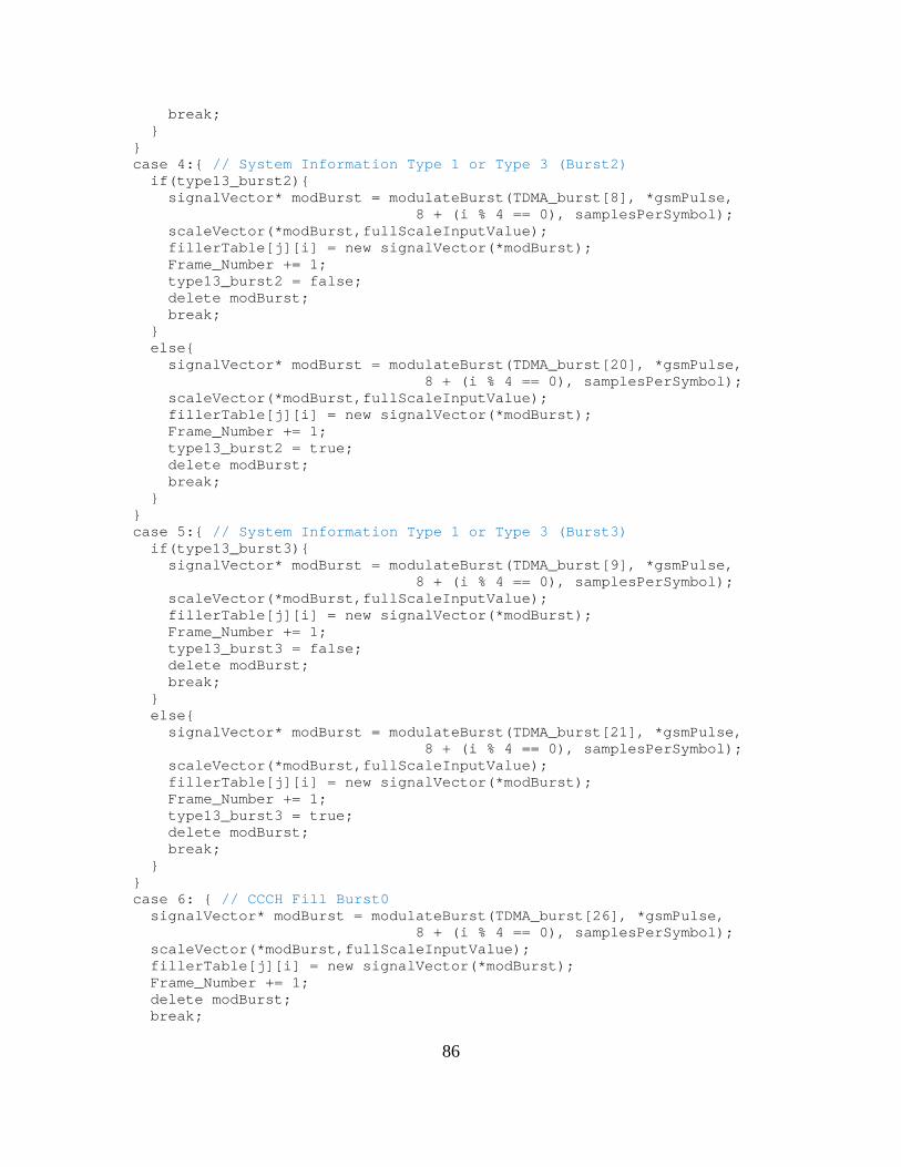
86
break; } } case 4:{ // System Information Type 1 or Type 3 (Burst2) if(type13_burst2){ signalVector* modBurst = modulateBurst(TDMA_burst[8], *gsmPulse, 8 + (i % 4 == 0), samplesPerSymbol); scaleVector(*modBurst,fullScaleInputValue); fillerTable[j][i] = new signalVector(*modBurst); Frame_Number += 1; type13_burst2 = false; delete modBurst; break; } else{ signalVector* modBurst = modulateBurst(TDMA_burst[20], *gsmPulse, 8 + (i % 4 == 0), samplesPerSymbol); scaleVector(*modBurst,fullScaleInputValue); fillerTable[j][i] = new signalVector(*modBurst); Frame_Number += 1; type13_burst2 = true; delete modBurst; break; } } case 5:{ // System Information Type 1 or Type 3 (Burst3) if(type13_burst3){ signalVector* modBurst = modulateBurst(TDMA_burst[9], *gsmPulse, 8 + (i % 4 == 0), samplesPerSymbol); scaleVector(*modBurst,fullScaleInputValue); fillerTable[j][i] = new signalVector(*modBurst); Frame_Number += 1; type13_burst3 = false; delete modBurst; break; } else{ signalVector* modBurst = modulateBurst(TDMA_burst[21], *gsmPulse, 8 + (i % 4 == 0), samplesPerSymbol); scaleVector(*modBurst,fullScaleInputValue); fillerTable[j][i] = new signalVector(*modBurst); Frame_Number += 1; type13_burst3 = true; delete modBurst; break; } } case 6: { // CCCH Fill Burst0 signalVector* modBurst = modulateBurst(TDMA_burst[26], *gsmPulse, 8 + (i % 4 == 0), samplesPerSymbol); scaleVector(*modBurst,fullScaleInputValue); fillerTable[j][i] = new signalVector(*modBurst); Frame_Number += 1; delete modBurst; break;

87
} case 7: { // CCCH Fill Burst1 signalVector* modBurst = modulateBurst(TDMA_burst[27], *gsmPulse, 8 + (i % 4 == 0), samplesPerSymbol); scaleVector(*modBurst,fullScaleInputValue); fillerTable[j][i] = new signalVector(*modBurst); Frame_Number += 1; delete modBurst; break; } case 8: { // CCCH Fill Burst2) signalVector* modBurst = modulateBurst(TDMA_burst[28], *gsmPulse, 8 + (i % 4 == 0), samplesPerSymbol); scaleVector(*modBurst,fullScaleInputValue); fillerTable[j][i] = new signalVector(*modBurst); Frame_Number += 1; delete modBurst; break; } case 9: { // CCCH Fill Burst3 signalVector* modBurst = modulateBurst(TDMA_burst[29], *gsmPulse, 8 + (i % 4 == 0), samplesPerSymbol); scaleVector(*modBurst,fullScaleInputValue); fillerTable[j][i] = new signalVector(*modBurst); Frame_Number += 1; delete modBurst; break; } case 10:{ // Frequency Burst signalVector* modBurst = modulateBurst(TDMA_burst[0], *gsmPulse, 8 + (i % 4 == 0), samplesPerSymbol); scaleVector(*modBurst,fullScaleInputValue); fillerTable[j][i] = new signalVector(*modBurst); Frame_Number += 1; delete modBurst; break; } case 11:{ // Synchronization Burst BitVector current_sync_burst = sync_burst_creator(Frame_Number); signalVector* modBurst = modulateBurst(current_sync_burst, *gsmPulse, 8 + (i % 4 == 0), samplesPerSymbol); scaleVector(*modBurst,fullScaleInputValue); fillerTable[j][i] = new signalVector(*modBurst); Frame_Number += 1; delete modBurst; break; } case 12: { // Paging Request Type 1 Burst0 signalVector* modBurst = modulateBurst(TDMA_burst[2], *gsmPulse, 8 + (i % 4 == 0), samplesPerSymbol); scaleVector(*modBurst,fullScaleInputValue); fillerTable[j][i] = new signalVector(*modBurst); Frame_Number += 1; delete modBurst; break;
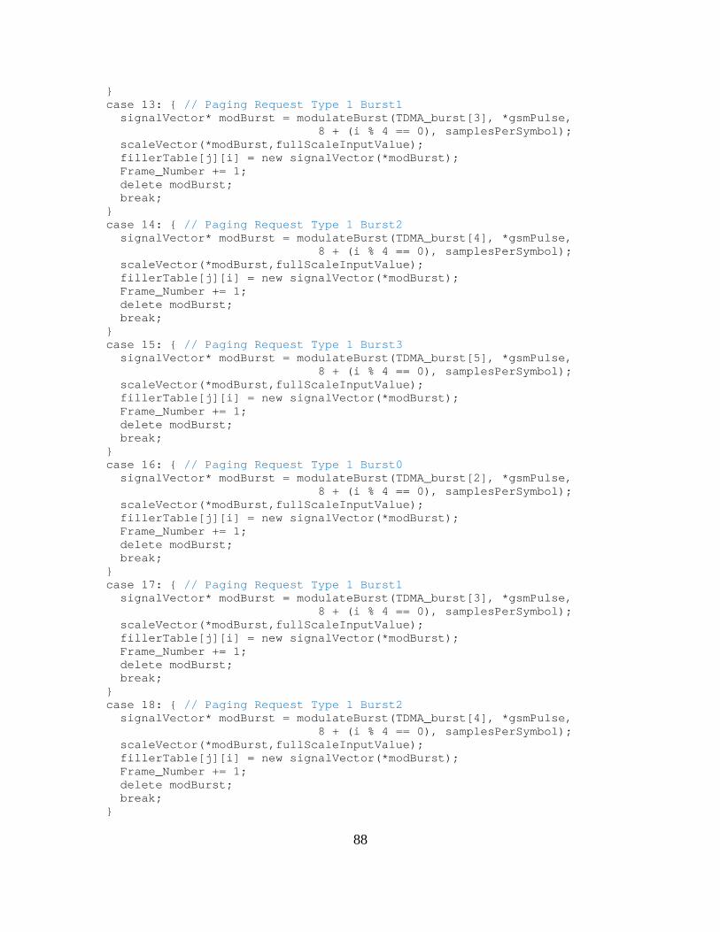
88
} case 13: { // Paging Request Type 1 Burst1 signalVector* modBurst = modulateBurst(TDMA_burst[3], *gsmPulse, 8 + (i % 4 == 0), samplesPerSymbol); scaleVector(*modBurst,fullScaleInputValue); fillerTable[j][i] = new signalVector(*modBurst); Frame_Number += 1; delete modBurst; break; } case 14: { // Paging Request Type 1 Burst2 signalVector* modBurst = modulateBurst(TDMA_burst[4], *gsmPulse, 8 + (i % 4 == 0), samplesPerSymbol); scaleVector(*modBurst,fullScaleInputValue); fillerTable[j][i] = new signalVector(*modBurst); Frame_Number += 1; delete modBurst; break; } case 15: { // Paging Request Type 1 Burst3 signalVector* modBurst = modulateBurst(TDMA_burst[5], *gsmPulse, 8 + (i % 4 == 0), samplesPerSymbol); scaleVector(*modBurst,fullScaleInputValue); fillerTable[j][i] = new signalVector(*modBurst); Frame_Number += 1; delete modBurst; break; } case 16: { // Paging Request Type 1 Burst0 signalVector* modBurst = modulateBurst(TDMA_burst[2], *gsmPulse, 8 + (i % 4 == 0), samplesPerSymbol); scaleVector(*modBurst,fullScaleInputValue); fillerTable[j][i] = new signalVector(*modBurst); Frame_Number += 1; delete modBurst; break; } case 17: { // Paging Request Type 1 Burst1 signalVector* modBurst = modulateBurst(TDMA_burst[3], *gsmPulse, 8 + (i % 4 == 0), samplesPerSymbol); scaleVector(*modBurst,fullScaleInputValue); fillerTable[j][i] = new signalVector(*modBurst); Frame_Number += 1; delete modBurst; break; } case 18: { // Paging Request Type 1 Burst2 signalVector* modBurst = modulateBurst(TDMA_burst[4], *gsmPulse, 8 + (i % 4 == 0), samplesPerSymbol); scaleVector(*modBurst,fullScaleInputValue); fillerTable[j][i] = new signalVector(*modBurst); Frame_Number += 1; delete modBurst; break; }
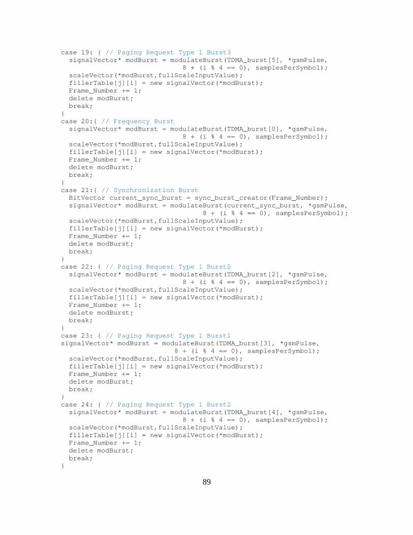
89
case 19: { // Paging Request Type 1 Burst3 signalVector* modBurst = modulateBurst(TDMA_burst[5], *gsmPulse, 8 + (i % 4 == 0), samplesPerSymbol); scaleVector(*modBurst,fullScaleInputValue); fillerTable[j][i] = new signalVector(*modBurst); Frame_Number += 1; delete modBurst; break; } case 20:{ // Frequency Burst signalVector* modBurst = modulateBurst(TDMA_burst[0], *gsmPulse, 8 + (i % 4 == 0), samplesPerSymbol); scaleVector(*modBurst,fullScaleInputValue); fillerTable[j][i] = new signalVector(*modBurst); Frame_Number += 1; delete modBurst; break; } case 21:{ // Synchronization Burst BitVector current_sync_burst = sync_burst_creator(Frame_Number); signalVector* modBurst = modulateBurst(current_sync_burst, *gsmPulse, 8 + (i % 4 == 0), samplesPerSymbol); scaleVector(*modBurst,fullScaleInputValue); fillerTable[j][i] = new signalVector(*modBurst); Frame_Number += 1; delete modBurst; break; } case 22: { // Paging Request Type 1 Burst0 signalVector* modBurst = modulateBurst(TDMA_burst[2], *gsmPulse, 8 + (i % 4 == 0), samplesPerSymbol); scaleVector(*modBurst,fullScaleInputValue); fillerTable[j][i] = new signalVector(*modBurst); Frame_Number += 1; delete modBurst; break; } case 23: { // Paging Request Type 1 Burst1 signalVector* modBurst = modulateBurst(TDMA_burst[3], *gsmPulse, 8 + (i % 4 == 0), samplesPerSymbol); scaleVector(*modBurst,fullScaleInputValue); fillerTable[j][i] = new signalVector(*modBurst); Frame_Number += 1; delete modBurst; break; } case 24: { // Paging Request Type 1 Burst2 signalVector* modBurst = modulateBurst(TDMA_burst[4], *gsmPulse, 8 + (i % 4 == 0), samplesPerSymbol); scaleVector(*modBurst,fullScaleInputValue); fillerTable[j][i] = new signalVector(*modBurst); Frame_Number += 1; delete modBurst; break; }
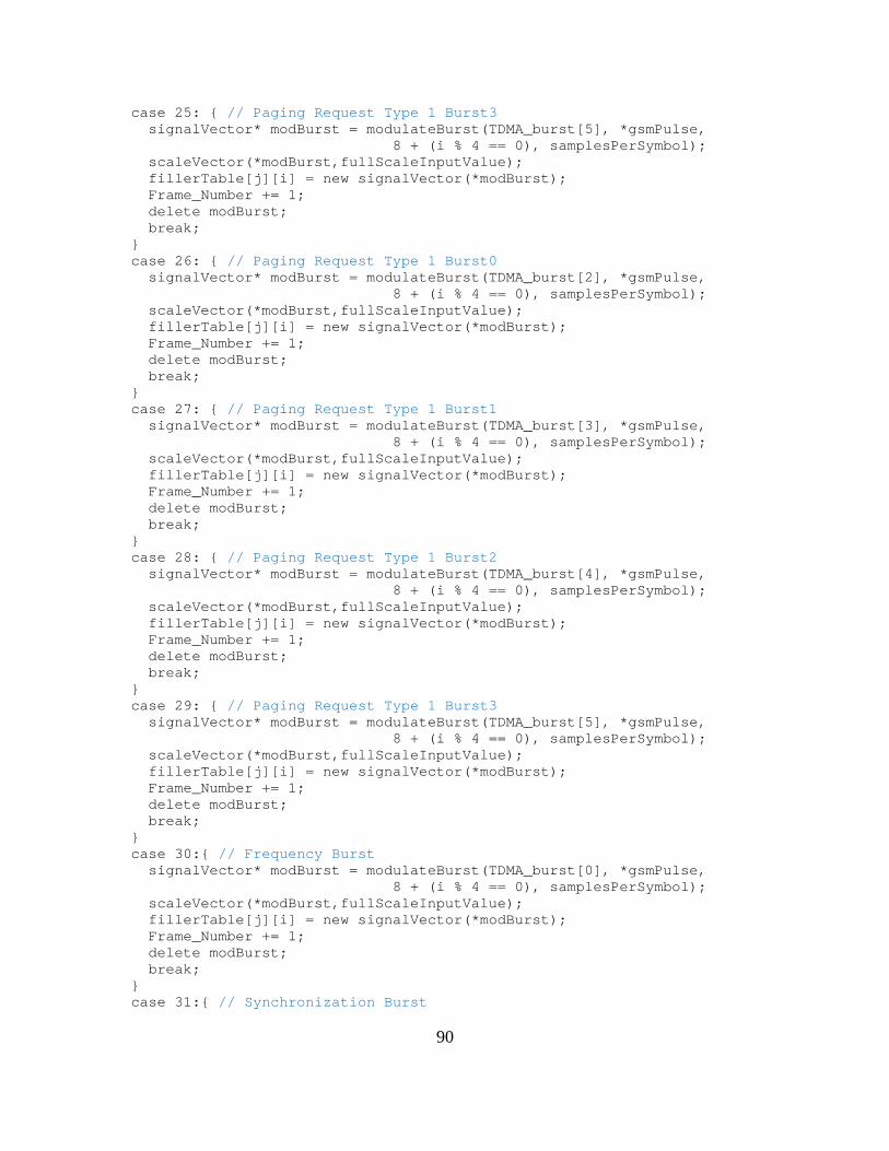
90
case 25: { // Paging Request Type 1 Burst3 signalVector* modBurst = modulateBurst(TDMA_burst[5], *gsmPulse, 8 + (i % 4 == 0), samplesPerSymbol); scaleVector(*modBurst,fullScaleInputValue); fillerTable[j][i] = new signalVector(*modBurst); Frame_Number += 1; delete modBurst; break; } case 26: { // Paging Request Type 1 Burst0 signalVector* modBurst = modulateBurst(TDMA_burst[2], *gsmPulse, 8 + (i % 4 == 0), samplesPerSymbol); scaleVector(*modBurst,fullScaleInputValue); fillerTable[j][i] = new signalVector(*modBurst); Frame_Number += 1; delete modBurst; break; } case 27: { // Paging Request Type 1 Burst1 signalVector* modBurst = modulateBurst(TDMA_burst[3], *gsmPulse, 8 + (i % 4 == 0), samplesPerSymbol); scaleVector(*modBurst,fullScaleInputValue); fillerTable[j][i] = new signalVector(*modBurst); Frame_Number += 1; delete modBurst; break; } case 28: { // Paging Request Type 1 Burst2 signalVector* modBurst = modulateBurst(TDMA_burst[4], *gsmPulse, 8 + (i % 4 == 0), samplesPerSymbol); scaleVector(*modBurst,fullScaleInputValue); fillerTable[j][i] = new signalVector(*modBurst); Frame_Number += 1; delete modBurst; break; } case 29: { // Paging Request Type 1 Burst3 signalVector* modBurst = modulateBurst(TDMA_burst[5], *gsmPulse, 8 + (i % 4 == 0), samplesPerSymbol); scaleVector(*modBurst,fullScaleInputValue); fillerTable[j][i] = new signalVector(*modBurst); Frame_Number += 1; delete modBurst; break; } case 30:{ // Frequency Burst signalVector* modBurst = modulateBurst(TDMA_burst[0], *gsmPulse, 8 + (i % 4 == 0), samplesPerSymbol); scaleVector(*modBurst,fullScaleInputValue); fillerTable[j][i] = new signalVector(*modBurst); Frame_Number += 1; delete modBurst; break; } case 31:{ // Synchronization Burst
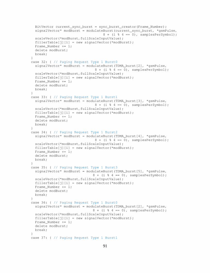
91
BitVector current_sync_burst = sync_burst_creator(Frame_Number); signalVector* modBurst = modulateBurst(current_sync_burst, *gsmPulse, 8 + (i % 4 == 0), samplesPerSymbol); scaleVector(*modBurst,fullScaleInputValue); fillerTable[j][i] = new signalVector(*modBurst); Frame_Number += 1; delete modBurst; break; } case 32: { // Paging Request Type 1 Burst0 signalVector* modBurst = modulateBurst(TDMA_burst[2], *gsmPulse, 8 + (i % 4 == 0), samplesPerSymbol); scaleVector(*modBurst,fullScaleInputValue); fillerTable[j][i] = new signalVector(*modBurst); Frame_Number += 1; delete modBurst; break; } case 33: { // Paging Request Type 1 Burst1 signalVector* modBurst = modulateBurst(TDMA_burst[3], *gsmPulse, 8 + (i % 4 == 0), samplesPerSymbol); scaleVector(*modBurst,fullScaleInputValue); fillerTable[j][i] = new signalVector(*modBurst); Frame_Number += 1; delete modBurst; break; } case 34: { // Paging Request Type 1 Burst2 signalVector* modBurst = modulateBurst(TDMA_burst[4], *gsmPulse, 8 + (i % 4 == 0), samplesPerSymbol); scaleVector(*modBurst,fullScaleInputValue); fillerTable[j][i] = new signalVector(*modBurst); Frame_Number += 1; delete modBurst; break; } case 35: { // Paging Request Type 1 Burst3 signalVector* modBurst = modulateBurst(TDMA_burst[5], *gsmPulse, 8 + (i % 4 == 0), samplesPerSymbol); scaleVector(*modBurst,fullScaleInputValue); fillerTable[j][i] = new signalVector(*modBurst); Frame_Number += 1; delete modBurst; break; } case 36: { // Paging Request Type 1 Burst0 signalVector* modBurst = modulateBurst(TDMA_burst[2], *gsmPulse, 8 + (i % 4 == 0), samplesPerSymbol); scaleVector(*modBurst,fullScaleInputValue); fillerTable[j][i] = new signalVector(*modBurst); Frame_Number += 1; delete modBurst; break; } case 37: { // Paging Request Type 1 Burst1
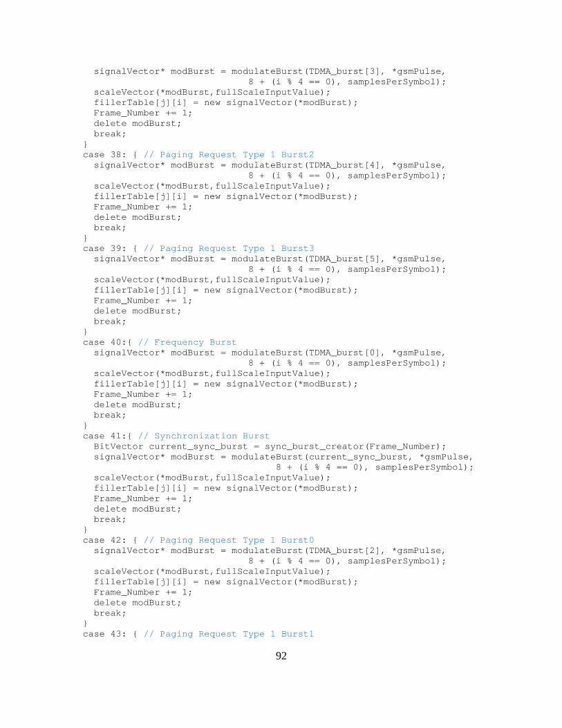
92
signalVector* modBurst = modulateBurst(TDMA_burst[3], *gsmPulse, 8 + (i % 4 == 0), samplesPerSymbol); scaleVector(*modBurst,fullScaleInputValue); fillerTable[j][i] = new signalVector(*modBurst); Frame_Number += 1; delete modBurst; break; } case 38: { // Paging Request Type 1 Burst2 signalVector* modBurst = modulateBurst(TDMA_burst[4], *gsmPulse, 8 + (i % 4 == 0), samplesPerSymbol); scaleVector(*modBurst,fullScaleInputValue); fillerTable[j][i] = new signalVector(*modBurst); Frame_Number += 1; delete modBurst; break; } case 39: { // Paging Request Type 1 Burst3 signalVector* modBurst = modulateBurst(TDMA_burst[5], *gsmPulse, 8 + (i % 4 == 0), samplesPerSymbol); scaleVector(*modBurst,fullScaleInputValue); fillerTable[j][i] = new signalVector(*modBurst); Frame_Number += 1; delete modBurst; break; } case 40:{ // Frequency Burst signalVector* modBurst = modulateBurst(TDMA_burst[0], *gsmPulse, 8 + (i % 4 == 0), samplesPerSymbol); scaleVector(*modBurst,fullScaleInputValue); fillerTable[j][i] = new signalVector(*modBurst); Frame_Number += 1; delete modBurst; break; } case 41:{ // Synchronization Burst BitVector current_sync_burst = sync_burst_creator(Frame_Number); signalVector* modBurst = modulateBurst(current_sync_burst, *gsmPulse, 8 + (i % 4 == 0), samplesPerSymbol); scaleVector(*modBurst,fullScaleInputValue); fillerTable[j][i] = new signalVector(*modBurst); Frame_Number += 1; delete modBurst; break; } case 42: { // Paging Request Type 1 Burst0 signalVector* modBurst = modulateBurst(TDMA_burst[2], *gsmPulse, 8 + (i % 4 == 0), samplesPerSymbol); scaleVector(*modBurst,fullScaleInputValue); fillerTable[j][i] = new signalVector(*modBurst); Frame_Number += 1; delete modBurst; break; } case 43: { // Paging Request Type 1 Burst1
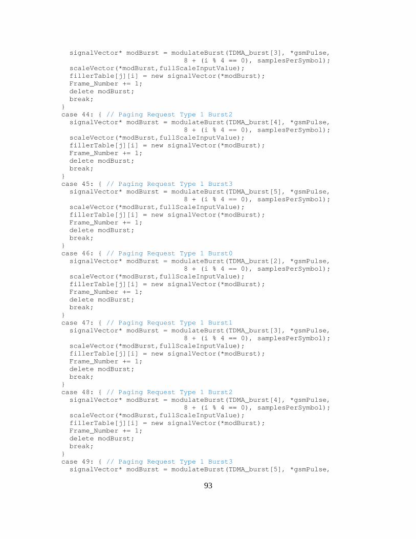
93
signalVector* modBurst = modulateBurst(TDMA_burst[3], *gsmPulse, 8 + (i % 4 == 0), samplesPerSymbol); scaleVector(*modBurst,fullScaleInputValue); fillerTable[j][i] = new signalVector(*modBurst); Frame_Number += 1; delete modBurst; break; } case 44: { // Paging Request Type 1 Burst2 signalVector* modBurst = modulateBurst(TDMA_burst[4], *gsmPulse, 8 + (i % 4 == 0), samplesPerSymbol); scaleVector(*modBurst,fullScaleInputValue); fillerTable[j][i] = new signalVector(*modBurst); Frame_Number += 1; delete modBurst; break; } case 45: { // Paging Request Type 1 Burst3 signalVector* modBurst = modulateBurst(TDMA_burst[5], *gsmPulse, 8 + (i % 4 == 0), samplesPerSymbol); scaleVector(*modBurst,fullScaleInputValue); fillerTable[j][i] = new signalVector(*modBurst); Frame_Number += 1; delete modBurst; break; } case 46: { // Paging Request Type 1 Burst0 signalVector* modBurst = modulateBurst(TDMA_burst[2], *gsmPulse, 8 + (i % 4 == 0), samplesPerSymbol); scaleVector(*modBurst,fullScaleInputValue); fillerTable[j][i] = new signalVector(*modBurst); Frame_Number += 1; delete modBurst; break; } case 47: { // Paging Request Type 1 Burst1 signalVector* modBurst = modulateBurst(TDMA_burst[3], *gsmPulse, 8 + (i % 4 == 0), samplesPerSymbol); scaleVector(*modBurst,fullScaleInputValue); fillerTable[j][i] = new signalVector(*modBurst); Frame_Number += 1; delete modBurst; break; } case 48: { // Paging Request Type 1 Burst2 signalVector* modBurst = modulateBurst(TDMA_burst[4], *gsmPulse, 8 + (i % 4 == 0), samplesPerSymbol); scaleVector(*modBurst,fullScaleInputValue); fillerTable[j][i] = new signalVector(*modBurst); Frame_Number += 1; delete modBurst; break; } case 49: { // Paging Request Type 1 Burst3 signalVector* modBurst = modulateBurst(TDMA_burst[5], *gsmPulse,
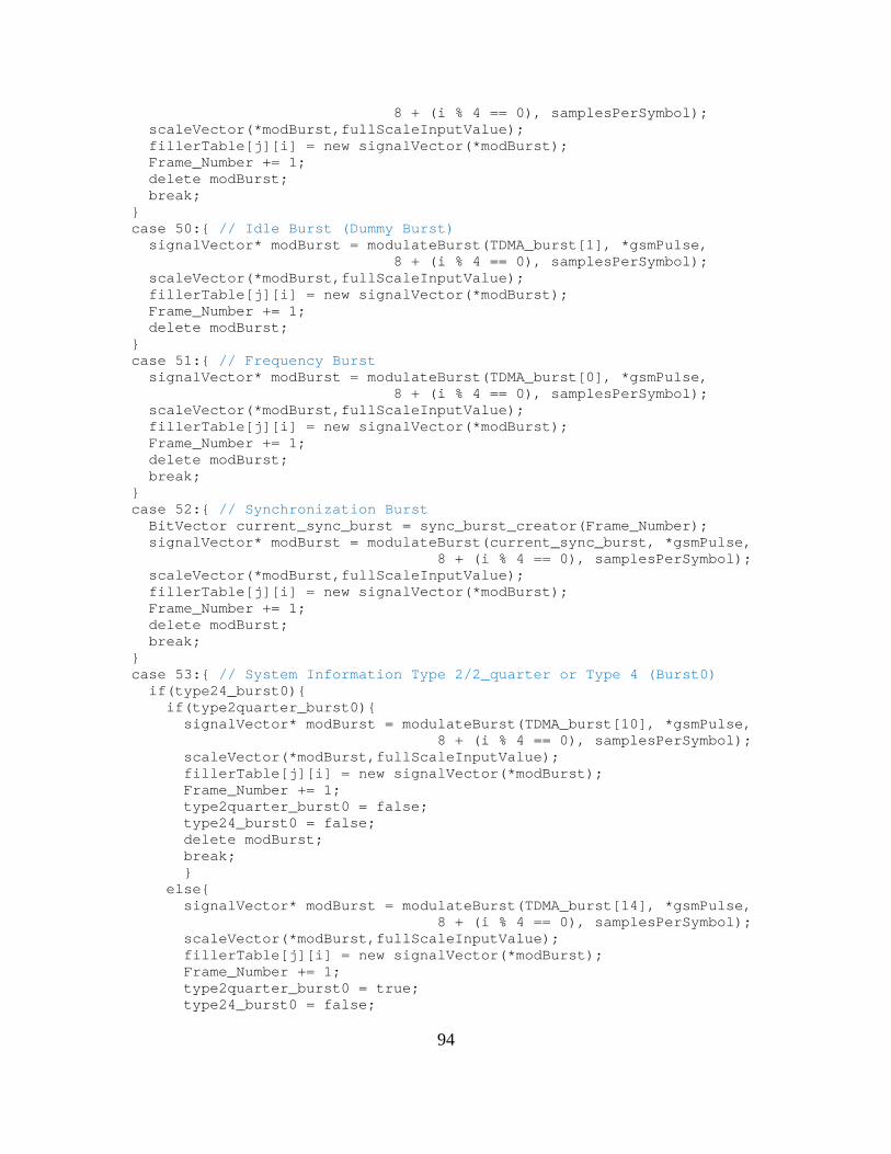
94
8 + (i % 4 == 0), samplesPerSymbol); scaleVector(*modBurst,fullScaleInputValue); fillerTable[j][i] = new signalVector(*modBurst); Frame_Number += 1; delete modBurst; break; } case 50:{ // Idle Burst (Dummy Burst) signalVector* modBurst = modulateBurst(TDMA_burst[1], *gsmPulse, 8 + (i % 4 == 0), samplesPerSymbol); scaleVector(*modBurst,fullScaleInputValue); fillerTable[j][i] = new signalVector(*modBurst); Frame_Number += 1; delete modBurst; } case 51:{ // Frequency Burst signalVector* modBurst = modulateBurst(TDMA_burst[0], *gsmPulse, 8 + (i % 4 == 0), samplesPerSymbol); scaleVector(*modBurst,fullScaleInputValue); fillerTable[j][i] = new signalVector(*modBurst); Frame_Number += 1; delete modBurst; break; } case 52:{ // Synchronization Burst BitVector current_sync_burst = sync_burst_creator(Frame_Number); signalVector* modBurst = modulateBurst(current_sync_burst, *gsmPulse, 8 + (i % 4 == 0), samplesPerSymbol); scaleVector(*modBurst,fullScaleInputValue); fillerTable[j][i] = new signalVector(*modBurst); Frame_Number += 1; delete modBurst; break; } case 53:{ // System Information Type 2/2_quarter or Type 4 (Burst0) if(type24_burst0){ if(type2quarter_burst0){ signalVector* modBurst = modulateBurst(TDMA_burst[10], *gsmPulse, 8 + (i % 4 == 0), samplesPerSymbol); scaleVector(*modBurst,fullScaleInputValue); fillerTable[j][i] = new signalVector(*modBurst); Frame_Number += 1; type2quarter_burst0 = false; type24_burst0 = false; delete modBurst; break; } else{ signalVector* modBurst = modulateBurst(TDMA_burst[14], *gsmPulse, 8 + (i % 4 == 0), samplesPerSymbol); scaleVector(*modBurst,fullScaleInputValue); fillerTable[j][i] = new signalVector(*modBurst); Frame_Number += 1; type2quarter_burst0 = true; type24_burst0 = false;

95
delete modBurst; break; } } else{ signalVector* modBurst = modulateBurst(TDMA_burst[22], *gsmPulse, 8 + (i % 4 == 0), samplesPerSymbol); scaleVector(*modBurst,fullScaleInputValue); fillerTable[j][i] = new signalVector(*modBurst); Frame_Number += 1; type24_burst0 = true; delete modBurst; break; } } case 54:{ // System Information Type 2/2_quarter or Type 4 (Burst1) if(type24_burst1){ if(type2quarter_burst1){ signalVector* modBurst = modulateBurst(TDMA_burst[11], *gsmPulse, 8 + (i % 4 == 0), samplesPerSymbol); scaleVector(*modBurst,fullScaleInputValue); fillerTable[j][i] = new signalVector(*modBurst); Frame_Number += 1; type2quarter_burst1 = false; type24_burst1 = false; delete modBurst; break; } else{ signalVector* modBurst = modulateBurst(TDMA_burst[15], *gsmPulse, 8 + (i % 4 == 0), samplesPerSymbol); scaleVector(*modBurst,fullScaleInputValue); fillerTable[j][i] = new signalVector(*modBurst); Frame_Number += 1; type2quarter_burst1 = true; type24_burst1 = false; delete modBurst; break; } } else{ signalVector* modBurst = modulateBurst(TDMA_burst[23], *gsmPulse, 8 + (i % 4 == 0), samplesPerSymbol); scaleVector(*modBurst,fullScaleInputValue); fillerTable[j][i] = new signalVector(*modBurst); Frame_Number += 1; type24_burst1 = true; delete modBurst; break; } } case 55:{ // System Information Type 2/2_quarter or Type 4 (Burst2) if(type24_burst2){ if(type2quarter_burst2){ signalVector* modBurst = modulateBurst(TDMA_burst[12], *gsmPulse,

96
8 + (i % 4 == 0), samplesPerSymbol); scaleVector(*modBurst,fullScaleInputValue); fillerTable[j][i] = new signalVector(*modBurst); Frame_Number += 1; type2quarter_burst2 = false; type24_burst2 = false; delete modBurst; break; } else{ signalVector* modBurst = modulateBurst(TDMA_burst[16], *gsmPulse, 8 + (i % 4 == 0), samplesPerSymbol); scaleVector(*modBurst,fullScaleInputValue); fillerTable[j][i] = new signalVector(*modBurst); Frame_Number += 1; type2quarter_burst2 = true; type24_burst2 = false; delete modBurst; break; } } else{ signalVector* modBurst = modulateBurst(TDMA_burst[24], *gsmPulse, 8 + (i % 4 == 0), samplesPerSymbol); scaleVector(*modBurst,fullScaleInputValue); fillerTable[j][i] = new signalVector(*modBurst); Frame_Number += 1; type24_burst2 = true; delete modBurst; break; } } case 56:{ // System Information Type 2/2_quarter or Type 4 (Burst3) if(type24_burst3){ if(type2quarter_burst3){ signalVector* modBurst = modulateBurst(TDMA_burst[13], *gsmPulse, 8 + (i % 4 == 0), samplesPerSymbol); scaleVector(*modBurst,fullScaleInputValue); fillerTable[j][i] = new signalVector(*modBurst); Frame_Number += 1; type2quarter_burst3 = false; type24_burst3 = false; delete modBurst; break; } else{ signalVector* modBurst = modulateBurst(TDMA_burst[17], *gsmPulse, 8 + (i % 4 == 0), samplesPerSymbol); scaleVector(*modBurst,fullScaleInputValue); fillerTable[j][i] = new signalVector(*modBurst); Frame_Number += 1; type2quarter_burst3 = true; type24_burst3 = false; delete modBurst; break;
97
} } else{ signalVector* modBurst = modulateBurst(TDMA_burst[25], *gsmPulse, 8 + (i % 4 == 0), samplesPerSymbol); scaleVector(*modBurst,fullScaleInputValue); fillerTable[j][i] = new signalVector(*modBurst); Frame_Number += 1; type24_burst3 = true; delete modBurst; break; } } case 57: { // CCCH Fill Burst0 signalVector* modBurst = modulateBurst(TDMA_burst[26], *gsmPulse, 8 + (i % 4 == 0), samplesPerSymbol); scaleVector(*modBurst,fullScaleInputValue); fillerTable[j][i] = new signalVector(*modBurst); Frame_Number += 1; delete modBurst; break; } case 58: { // CCCH Fill Burst1 signalVector* modBurst = modulateBurst(TDMA_burst[27], *gsmPulse, 8 + (i % 4 == 0), samplesPerSymbol); scaleVector(*modBurst,fullScaleInputValue); fillerTable[j][i] = new signalVector(*modBurst); Frame_Number += 1; delete modBurst; break; } case 59: { // CCCH Fill Burst2 signalVector* modBurst = modulateBurst(TDMA_burst[28], *gsmPulse, 8 + (i % 4 == 0), samplesPerSymbol); scaleVector(*modBurst,fullScaleInputValue); fillerTable[j][i] = new signalVector(*modBurst); Frame_Number += 1; delete modBurst; break; } case 60: { // CCCH Fill Burst3 signalVector* modBurst = modulateBurst(TDMA_burst[29], *gsmPulse, 8 + (i % 4 == 0), samplesPerSymbol); scaleVector(*modBurst,fullScaleInputValue); fillerTable[j][i] = new signalVector(*modBurst); Frame_Number += 1; delete modBurst; break; } case 61:{ // Frequency Burst signalVector* modBurst = modulateBurst(TDMA_burst[0], *gsmPulse, 8 + (i % 4 == 0), samplesPerSymbol); scaleVector(*modBurst,fullScaleInputValue); fillerTable[j][i] = new signalVector(*modBurst); Frame_Number += 1;
98
delete modBurst; break; } case 62:{ // Synchronization Burst BitVector current_sync_burst = sync_burst_creator(Frame_Number); signalVector* modBurst = modulateBurst(current_sync_burst, *gsmPulse, 8 + (i % 4 == 0), samplesPerSymbol); scaleVector(*modBurst,fullScaleInputValue); fillerTable[j][i] = new signalVector(*modBurst); Frame_Number += 1; delete modBurst; break; } case 63: { // Paging Request Type 1 Burst0 signalVector* modBurst = modulateBurst(TDMA_burst[2], *gsmPulse, 8 + (i % 4 == 0), samplesPerSymbol); scaleVector(*modBurst,fullScaleInputValue); fillerTable[j][i] = new signalVector(*modBurst); Frame_Number += 1; delete modBurst; break; } case 64: { // Paging Request Type 1 Burst1 signalVector* modBurst = modulateBurst(TDMA_burst[3], *gsmPulse, 8 + (i % 4 == 0), samplesPerSymbol); scaleVector(*modBurst,fullScaleInputValue); fillerTable[j][i] = new signalVector(*modBurst); Frame_Number += 1; delete modBurst; break; } case 65: { // Paging Request Type 1 Burst2 signalVector* modBurst = modulateBurst(TDMA_burst[4], *gsmPulse, 8 + (i % 4 == 0), samplesPerSymbol); scaleVector(*modBurst,fullScaleInputValue); fillerTable[j][i] = new signalVector(*modBurst); Frame_Number += 1; delete modBurst; break; } case 66: { // Paging Request Type 1 Burst3 signalVector* modBurst = modulateBurst(TDMA_burst[5], *gsmPulse, 8 + (i % 4 == 0), samplesPerSymbol); scaleVector(*modBurst,fullScaleInputValue); fillerTable[j][i] = new signalVector(*modBurst); Frame_Number += 1; delete modBurst; break; } case 67: { // Paging Request Type 1 Burst0 signalVector* modBurst = modulateBurst(TDMA_burst[2], *gsmPulse, 8 + (i % 4 == 0), samplesPerSymbol); scaleVector(*modBurst,fullScaleInputValue); fillerTable[j][i] = new signalVector(*modBurst); Frame_Number += 1;
99
delete modBurst; break; } case 68: { // Paging Request Type 1 Burst1 signalVector* modBurst = modulateBurst(TDMA_burst[3], *gsmPulse, 8 + (i % 4 == 0), samplesPerSymbol); scaleVector(*modBurst,fullScaleInputValue); fillerTable[j][i] = new signalVector(*modBurst); Frame_Number += 1; delete modBurst; break; } case 69: { // Paging Request Type 1 Burst2 signalVector* modBurst = modulateBurst(TDMA_burst[4], *gsmPulse, 8 + (i % 4 == 0), samplesPerSymbol); scaleVector(*modBurst,fullScaleInputValue); fillerTable[j][i] = new signalVector(*modBurst); Frame_Number += 1; delete modBurst; break; } case 70: { // Paging Request Type 1 Burst3 signalVector* modBurst = modulateBurst(TDMA_burst[5], *gsmPulse, 8 + (i % 4 == 0), samplesPerSymbol); scaleVector(*modBurst,fullScaleInputValue); fillerTable[j][i] = new signalVector(*modBurst); Frame_Number += 1; delete modBurst; break; } case 71:{ // Frequency Burst signalVector* modBurst = modulateBurst(TDMA_burst[0], *gsmPulse, 8 + (i % 4 == 0), samplesPerSymbol); scaleVector(*modBurst,fullScaleInputValue); fillerTable[j][i] = new signalVector(*modBurst); Frame_Number += 1; delete modBurst; break; } case 72:{ // Synchronization Burst BitVector current_sync_burst = sync_burst_creator(Frame_Number); signalVector* modBurst = modulateBurst(current_sync_burst, *gsmPulse, 8 + (i % 4 == 0), samplesPerSymbol); scaleVector(*modBurst,fullScaleInputValue); fillerTable[j][i] = new signalVector(*modBurst); Frame_Number += 1; delete modBurst; break; } case 73: { // Paging Request Type 1 Burst0 signalVector* modBurst = modulateBurst(TDMA_burst[2], *gsmPulse, 8 + (i % 4 == 0), samplesPerSymbol); scaleVector(*modBurst,fullScaleInputValue); fillerTable[j][i] = new signalVector(*modBurst); Frame_Number += 1;
100
delete modBurst; break; } case 74: { // Paging Request Type 1 Burst1 signalVector* modBurst = modulateBurst(TDMA_burst[3], *gsmPulse, 8 + (i % 4 == 0), samplesPerSymbol); scaleVector(*modBurst,fullScaleInputValue); fillerTable[j][i] = new signalVector(*modBurst); Frame_Number += 1; delete modBurst; break; } case 75: { // Paging Request Type 1 Burst2 signalVector* modBurst = modulateBurst(TDMA_burst[4], *gsmPulse, 8 + (i % 4 == 0), samplesPerSymbol); scaleVector(*modBurst,fullScaleInputValue); fillerTable[j][i] = new signalVector(*modBurst); Frame_Number += 1; delete modBurst; break; } case 76: { // Paging Request Type 1 Burst3 signalVector* modBurst = modulateBurst(TDMA_burst[5], *gsmPulse, 8 + (i % 4 == 0), samplesPerSymbol); scaleVector(*modBurst,fullScaleInputValue); fillerTable[j][i] = new signalVector(*modBurst); Frame_Number += 1; delete modBurst; break; } case 77: { // Paging Request Type 1 Burst0 signalVector* modBurst = modulateBurst(TDMA_burst[2], *gsmPulse, 8 + (i % 4 == 0), samplesPerSymbol); scaleVector(*modBurst,fullScaleInputValue); fillerTable[j][i] = new signalVector(*modBurst); Frame_Number += 1; delete modBurst; break; } case 78: { // Paging Request Type 1 Burst1 signalVector* modBurst = modulateBurst(TDMA_burst[3], *gsmPulse, 8 + (i % 4 == 0), samplesPerSymbol); scaleVector(*modBurst,fullScaleInputValue); fillerTable[j][i] = new signalVector(*modBurst); Frame_Number += 1; delete modBurst; break; } case 79: { // Paging Request Type 1 Burst2 signalVector* modBurst = modulateBurst(TDMA_burst[4], *gsmPulse, 8 + (i % 4 == 0), samplesPerSymbol); scaleVector(*modBurst,fullScaleInputValue); fillerTable[j][i] = new signalVector(*modBurst); Frame_Number += 1; delete modBurst;
101
break; } case 80: { // Paging Request Type 1 Burst3 signalVector* modBurst = modulateBurst(TDMA_burst[5], *gsmPulse, 8 + (i % 4 == 0), samplesPerSymbol); scaleVector(*modBurst,fullScaleInputValue); fillerTable[j][i] = new signalVector(*modBurst); Frame_Number += 1; delete modBurst; break; } case 81:{ // Frequency Burst signalVector* modBurst = modulateBurst(TDMA_burst[0], *gsmPulse, 8 + (i % 4 == 0), samplesPerSymbol); scaleVector(*modBurst,fullScaleInputValue); fillerTable[j][i] = new signalVector(*modBurst); Frame_Number += 1; delete modBurst; break; } case 82:{ // Synchronization Burst BitVector current_sync_burst = sync_burst_creator(Frame_Number); signalVector* modBurst = modulateBurst(current_sync_burst, *gsmPulse, 8 + (i % 4 == 0), samplesPerSymbol); scaleVector(*modBurst,fullScaleInputValue); fillerTable[j][i] = new signalVector(*modBurst); Frame_Number += 1; delete modBurst; break; } case 83: { // Paging Request Type 1 Burst0 signalVector* modBurst = modulateBurst(TDMA_burst[2], *gsmPulse, 8 + (i % 4 == 0), samplesPerSymbol); scaleVector(*modBurst,fullScaleInputValue); fillerTable[j][i] = new signalVector(*modBurst); Frame_Number += 1; delete modBurst; break; } case 84: { // Paging Request Type 1 Burst1 signalVector* modBurst = modulateBurst(TDMA_burst[3], *gsmPulse, 8 + (i % 4 == 0), samplesPerSymbol); scaleVector(*modBurst,fullScaleInputValue); fillerTable[j][i] = new signalVector(*modBurst); Frame_Number += 1; delete modBurst; break; } case 85: { // Paging Request Type 1 Burst2 signalVector* modBurst = modulateBurst(TDMA_burst[4], *gsmPulse, 8 + (i % 4 == 0), samplesPerSymbol); scaleVector(*modBurst,fullScaleInputValue); fillerTable[j][i] = new signalVector(*modBurst); Frame_Number += 1; delete modBurst;
102
break; } case 86: { // Paging Request Type 1 Burst3 signalVector* modBurst = modulateBurst(TDMA_burst[5], *gsmPulse, 8 + (i % 4 == 0), samplesPerSymbol); scaleVector(*modBurst,fullScaleInputValue); fillerTable[j][i] = new signalVector(*modBurst); Frame_Number += 1; delete modBurst; break; } case 87: { // Paging Request Type 1 Burst0 signalVector* modBurst = modulateBurst(TDMA_burst[2], *gsmPulse, 8 + (i % 4 == 0), samplesPerSymbol); scaleVector(*modBurst,fullScaleInputValue); fillerTable[j][i] = new signalVector(*modBurst); Frame_Number += 1; delete modBurst; break; } case 88: { // Paging Request Type 1 Burst1 signalVector* modBurst = modulateBurst(TDMA_burst[3], *gsmPulse, 8 + (i % 4 == 0), samplesPerSymbol); scaleVector(*modBurst,fullScaleInputValue); fillerTable[j][i] = new signalVector(*modBurst); Frame_Number += 1; delete modBurst; break; } case 89: { // Paging Request Type 1 Burst2 signalVector* modBurst = modulateBurst(TDMA_burst[4], *gsmPulse, 8 + (i % 4 == 0), samplesPerSymbol); scaleVector(*modBurst,fullScaleInputValue); fillerTable[j][i] = new signalVector(*modBurst); Frame_Number += 1; delete modBurst; break; } case 90: { // Paging Request Type 1 Burst3 signalVector* modBurst = modulateBurst(TDMA_burst[5], *gsmPulse, 8 + (i % 4 == 0), samplesPerSymbol); scaleVector(*modBurst,fullScaleInputValue); fillerTable[j][i] = new signalVector(*modBurst); Frame_Number += 1; delete modBurst; break; } case 91:{ // Frequency Burst signalVector* modBurst = modulateBurst(TDMA_burst[0], *gsmPulse, 8 + (i % 4 == 0), samplesPerSymbol); scaleVector(*modBurst,fullScaleInputValue); fillerTable[j][i] = new signalVector(*modBurst); Frame_Number += 1; delete modBurst; break;
103
} case 92:{ // Synchronization Burst BitVector current_sync_burst = sync_burst_creator(Frame_Number); signalVector* modBurst = modulateBurst(current_sync_burst, *gsmPulse, 8 + (i % 4 == 0), samplesPerSymbol); scaleVector(*modBurst,fullScaleInputValue); fillerTable[j][i] = new signalVector(*modBurst); Frame_Number += 1; delete modBurst; break; } case 93: { // Paging Request Type 1 Burst0 signalVector* modBurst = modulateBurst(TDMA_burst[2], *gsmPulse, 8 + (i % 4 == 0), samplesPerSymbol); scaleVector(*modBurst,fullScaleInputValue); fillerTable[j][i] = new signalVector(*modBurst); Frame_Number += 1; delete modBurst; break; } case 94: { // Paging Request Type 1 Burst1 signalVector* modBurst = modulateBurst(TDMA_burst[3], *gsmPulse, 8 + (i % 4 == 0), samplesPerSymbol); scaleVector(*modBurst,fullScaleInputValue); fillerTable[j][i] = new signalVector(*modBurst); Frame_Number += 1; delete modBurst; break; } case 95: { // Paging Request Type 1 Burst2 signalVector* modBurst = modulateBurst(TDMA_burst[4], *gsmPulse, 8 + (i % 4 == 0), samplesPerSymbol); scaleVector(*modBurst,fullScaleInputValue); fillerTable[j][i] = new signalVector(*modBurst); Frame_Number += 1; delete modBurst; break; } case 96: { // Paging Request Type 1 Burst3 signalVector* modBurst = modulateBurst(TDMA_burst[5], *gsmPulse, 8 + (i % 4 == 0), samplesPerSymbol); scaleVector(*modBurst,fullScaleInputValue); fillerTable[j][i] = new signalVector(*modBurst); Frame_Number += 1; delete modBurst; break; } case 97: { // Paging Request Type 1 Burst0 signalVector* modBurst = modulateBurst(TDMA_burst[2], *gsmPulse, 8 + (i % 4 == 0), samplesPerSymbol); scaleVector(*modBurst,fullScaleInputValue); fillerTable[j][i] = new signalVector(*modBurst); Frame_Number += 1; delete modBurst; break;
104
} case 98: { // Paging Request Type 1 Burst1 signalVector* modBurst = modulateBurst(TDMA_burst[3], *gsmPulse, 8 + (i % 4 == 0), samplesPerSymbol); scaleVector(*modBurst,fullScaleInputValue); fillerTable[j][i] = new signalVector(*modBurst); Frame_Number += 1; delete modBurst; break; } case 99: { // Paging Request Type 1 Burst2 signalVector* modBurst = modulateBurst(TDMA_burst[4], *gsmPulse, 8 + (i % 4 == 0), samplesPerSymbol); scaleVector(*modBurst,fullScaleInputValue); fillerTable[j][i] = new signalVector(*modBurst); Frame_Number += 1; delete modBurst; break; } case 100: { // Paging Request Type 1 Burst3 signalVector* modBurst = modulateBurst(TDMA_burst[5], *gsmPulse, 8 + (i % 4 == 0), samplesPerSymbol); scaleVector(*modBurst,fullScaleInputValue); fillerTable[j][i] = new signalVector(*modBurst); Frame_Number += 1; delete modBurst; break; } case 101: { // Idle Burst (Dummy Burst) signalVector* modBurst = modulateBurst(TDMA_burst[1], *gsmPulse, 8 + (i % 4 == 0), samplesPerSymbol); scaleVector(*modBurst,fullScaleInputValue); fillerTable[j][i] = new signalVector(*modBurst); Frame_Number += 1; delete modBurst; } default:{ // Default fills bursts with Dummy Burst signalVector* modBurst = modulateBurst(TDMA_burst[1], *gsmPulse, 8 + (i % 4 == 0), samplesPerSymbol); scaleVector(*modBurst,fullScaleInputValue); fillerTable[j][i] = new signalVector(*modBurst); Frame_Number += 1; delete modBurst; } } // end switch } // end if else{ // Fill remaining timeslot [1–7] with Dummy Burst signalVector* modBurst = modulateBurst(TDMA_burst[1], *gsmPulse, 8 + (i % 4 == 0), samplesPerSymbol); scaleVector(*modBurst, fullScaleInputValue); fillerTable[j][i] = new signalVector(*modBurst); Frame_Number += 1; delete modBurst; } // end else
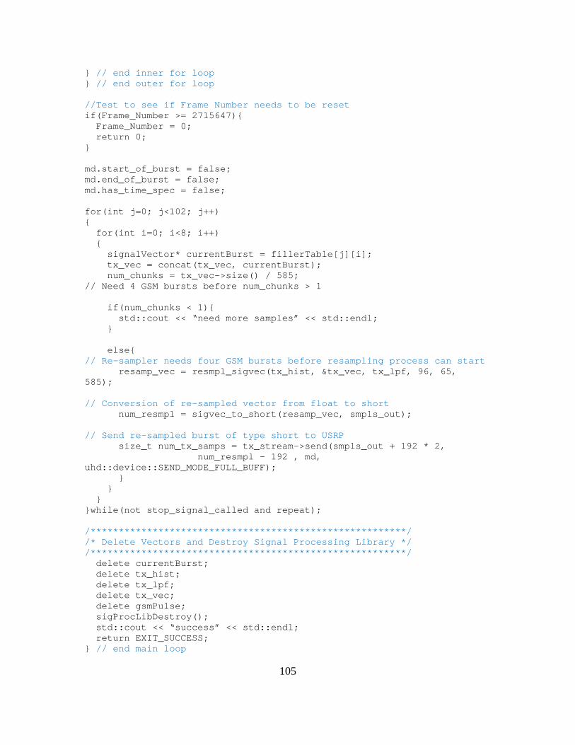
105
} // end inner for loop } // end outer for loop //Test to see if Frame Number needs to be reset if(Frame_Number >= 2715647){ Frame_Number = 0; return 0; } md.start_of_burst = false; md.end_of_burst = false; md.has_time_spec = false; for(int j=0; j<102; j++) { for(int i=0; i<8; i++) { signalVector* currentBurst = fillerTable[j][i]; tx_vec = concat(tx_vec, currentBurst); num_chunks = tx_vec->size() / 585; // Need 4 GSM bursts before num_chunks > 1 if(num_chunks < 1){ std::cout << “need more samples” << std::endl; } else{ // Re-sampler needs four GSM bursts before resampling process can start resamp_vec = resmpl_sigvec(tx_hist, &tx_vec, tx_lpf, 96, 65, 585); // Conversion of re-sampled vector from float to short num_resmpl = sigvec_to_short(resamp_vec, smpls_out); // Send re-sampled burst of type short to USRP size_t num_tx_samps = tx_stream->send(smpls_out + 192 * 2, num_resmpl - 192 , md, uhd::device::SEND_MODE_FULL_BUFF); } } } }while(not stop_signal_called and repeat); /********************************************************/ /* Delete Vectors and Destroy Signal Processing Library */ /********************************************************/ delete currentBurst; delete tx_hist; delete tx_lpf; delete tx_vec; delete gsmPulse; sigProcLibDestroy(); std::cout << “success” << std::endl; return EXIT_SUCCESS; } // end main loop

106
THIS PAGE INTENTIONALLY LEFT BLANK
107
APPENDIX C. GSM TRANSMITTER C++ CODE FOR TRIGGERED HANDOVER FAILURE MESSAGE
This appendix contains the code for the triggered GSM handover failure message
transmitter. Prior to using this code, the handover failure message must first be converted
from hexadecimal values to binary values by executing the
GSM_message_hexadecimal_to_binary.py code described in Appendix B.
Next, the binary output from the GSM_message_hexadecimal_to_binary.py
code is run through the GSM_Burst_Creator.cpp code to encode the data bits and
interleave them onto four GSM TDMA normal bursts. Finally, the four GSM TDMA
normal bursts are modulated, re-sampled and transmitted using the
GSM_Handover_Failure_Triggered_Transmitter.cpp code contained in
this appendix. Many of the functions in this code were originally written in OpenBTS [1];
therefore, it requires the following OpenBTS C++ source code files for proper execution:
sigProcLib.cpp, BitVector.cpp, GSMCommon.cpp, and Timeval.cpp. It
also requires the following dependencies when using an Ubuntu Linux load: libboost-all-
dev, libusb-1.0–0-dev, python-cheetah, doxygen, and python-docutils. Finally, the
GSM_Handover_Failure_Triggered_Transmitter.cpp requires installation
of Ettus UHD software.
A. GSM_HANDOVER_FAILURE_TRIGGERED_TRANSMITTER.CPP
#include <uhd/utils/thread_priority.hpp> #include <uhd/utils/safe_main.hpp> #include <uhd/utils/static.hpp> #include <uhd/usrp/multi_usrp.hpp> #include <uhd/exception.hpp> #include <uhd/stream.hpp> #include “sigProcLib.h” #include “BitVector.h” #include <boost/math/special_functions/round.hpp> #include <boost/date_time/posix_time/posix_time.hpp> #include <boost/foreach.hpp> #include <boost/format.hpp> #include <boost/thread.hpp> #include <iostream> #include <complex> #include <csignal> #include <algorithm> #include <fstream>
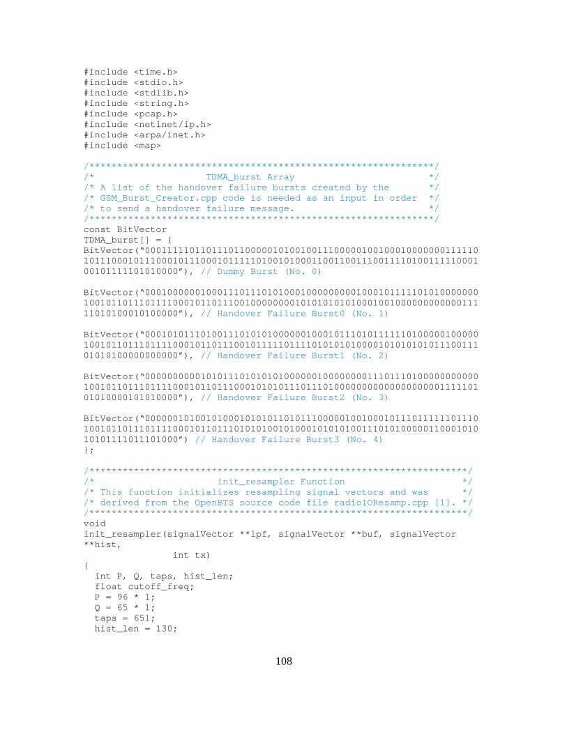
108
#include <time.h> #include <stdio.h> #include <stdlib.h> #include <string.h> #include <pcap.h> #include <netinet/ip.h> #include <arpa/inet.h> #include <map> /**************************************************************/ /* TDMA_burst Array */ /* A list of the handover failure bursts created by the */ /* GSM_Burst_Creator.cpp code is needed as an input in order */ /* to send a handover failure message. */ /**************************************************************/ const BitVector TDMA_burst[] = { BitVector(“0001111101101110110000010100100111000001001000100000001111101011100010111000101110001011111010010100011001100111001111010011111000100101111101010000”), // Dummy Burst (No. 0) BitVector(“0001000000100011101110101000100000000010001011111010100000001001011011101111000101101110010000000010101010101000100100000000000011111010100010100000”), // Handover Failure Burst0 (No. 1) BitVector(“0001010111010011101010100000010001011101011111101000001000001001011011101111000101101110010111110111101010101000010101010101110011101010100000000000”), // Handover Failure Burst1 (No. 2) BitVector(“0000000000101011101010101000000100000000111011101000000000001001011011101111000101101110001010101110111010000000000000000000111110101010000101010000”), // Handover Failure Burst2 (No. 3) BitVector(“0000001010010100010101011010111000001001000101110111111011101001011011101111000101101110101010010100010101010011101010000011000101010101111011101000”) // Handover Failure Burst3 (No. 4) }; /********************************************************************/ /* init_resampler Function */ /* This function initializes resampling signal vectors and was */ /* derived from the OpenBTS source code file radioIOResamp.cpp [1]. */ /********************************************************************/ void init_resampler(signalVector **lpf, signalVector **buf, signalVector **hist, int tx) { int P, Q, taps, hist_len; float cutoff_freq; P = 96 * 1; Q = 65 * 1; taps = 651; hist_len = 130;
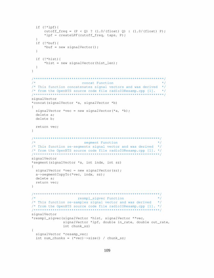
109
if (!*lpf){ cutoff_freq = (P < Q) ? (1.0/(float) Q) : (1.0/(float) P); *lpf = createLPF(cutoff_freq, taps, P); } if (!*buf){ *buf = new signalVector(); } if (!*hist){ *hist = new signalVector(hist_len); } } /**************************************************************/ /* concat Function */ /* This function concatenates signal vectors and was derived */ /* from the OpenBTS source code file radioIOResamp.cpp [1]. */ /**************************************************************/ signalVector *concat(signalVector *a, signalVector *b) { signalVector *vec = new signalVector(*a, *b); delete a; delete b; return vec; } /************************************************************/ /* segment Function */ /* This function re-segments signal vector and was derived */ /* from the OpenBTS source code file radioIOResamp.cpp [1]. */ /************************************************************/ signalVector *segment(signalVector *a, int indx, int sz) { signalVector *vec = new signalVector(sz); a->segmentCopyTo(*vec, indx, sz); delete a; return vec; } /************************************************************/ /* resmpl_sigvec Function */ /* This function re-samples signal vector and was derived */ /* from the OpenBTS source code file radioIOResamp.cpp [1]. */ /************************************************************/ signalVector *resmpl_sigvec(signalVector *hist, signalVector **vec, signalVector *lpf, double in_rate, double out_rate, int chunk_sz) { signalVector *resamp_vec; int num_chunks = (*vec)->size() / chunk_sz;
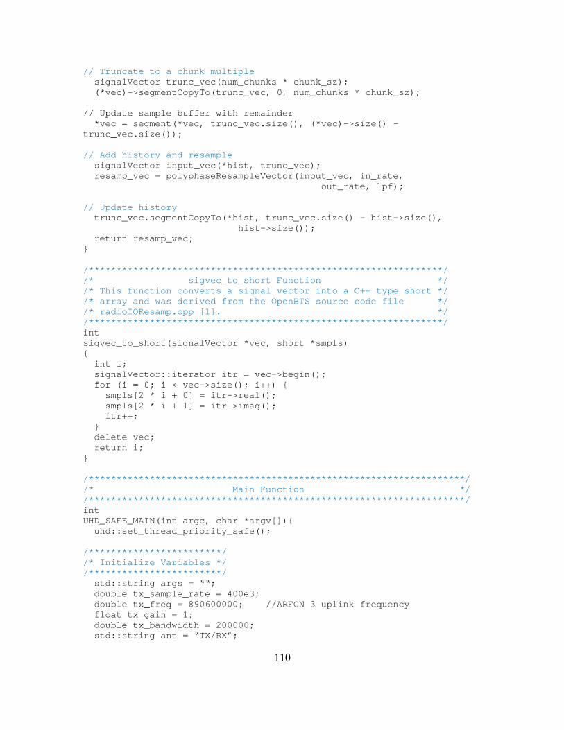
110
// Truncate to a chunk multiple signalVector trunc_vec(num_chunks * chunk_sz); (*vec)->segmentCopyTo(trunc_vec, 0, num_chunks * chunk_sz); // Update sample buffer with remainder *vec = segment(*vec, trunc_vec.size(), (*vec)->size() - trunc_vec.size()); // Add history and resample signalVector input_vec(*hist, trunc_vec); resamp_vec = polyphaseResampleVector(input_vec, in_rate, out_rate, lpf); // Update history trunc_vec.segmentCopyTo(*hist, trunc_vec.size() - hist->size(), hist->size()); return resamp_vec; } /****************************************************************/ /* sigvec_to_short Function */ /* This function converts a signal vector into a C++ type short */ /* array and was derived from the OpenBTS source code file */ /* radioIOResamp.cpp [1]. */ /****************************************************************/ int sigvec_to_short(signalVector *vec, short *smpls) { int i; signalVector::iterator itr = vec->begin(); for (i = 0; i < vec->size(); i++) { smpls[2 * i + 0] = itr->real(); smpls[2 * i + 1] = itr->imag(); itr++; } delete vec; return i; } /********************************************************************/ /* Main Function */ /********************************************************************/ int UHD_SAFE_MAIN(int argc, char *argv[]){ uhd::set_thread_priority_safe(); /************************/ /* Initialize Variables */ /************************/ std::string args = ““; double tx_sample_rate = 400e3; double tx_freq = 890600000; //ARFCN 3 uplink frequency float tx_gain = 1; double tx_bandwidth = 200000; std::string ant = “TX/RX”;
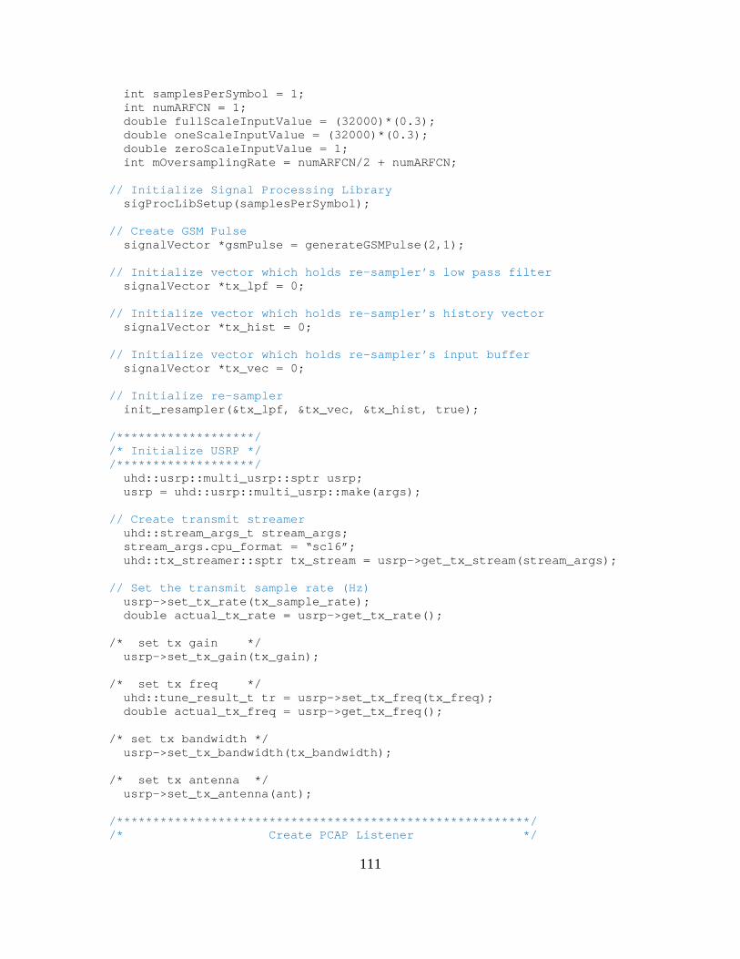
111
int samplesPerSymbol = 1; int numARFCN = 1; double fullScaleInputValue = (32000)*(0.3); double oneScaleInputValue = (32000)*(0.3); double zeroScaleInputValue = 1; int mOversamplingRate = numARFCN/2 + numARFCN; // Initialize Signal Processing Library sigProcLibSetup(samplesPerSymbol); // Create GSM Pulse signalVector *gsmPulse = generateGSMPulse(2,1); // Initialize vector which holds re-sampler’s low pass filter signalVector *tx_lpf = 0; // Initialize vector which holds re-sampler’s history vector signalVector *tx_hist = 0; // Initialize vector which holds re-sampler’s input buffer signalVector *tx_vec = 0; // Initialize re-sampler init_resampler(&tx_lpf, &tx_vec, &tx_hist, true); /*******************/ /* Initialize USRP */ /*******************/ uhd::usrp::multi_usrp::sptr usrp; usrp = uhd::usrp::multi_usrp::make(args); // Create transmit streamer uhd::stream_args_t stream_args; stream_args.cpu_format = “sc16”; uhd::tx_streamer::sptr tx_stream = usrp->get_tx_stream(stream_args); // Set the transmit sample rate (Hz) usrp->set_tx_rate(tx_sample_rate); double actual_tx_rate = usrp->get_tx_rate(); /* set tx gain */ usrp->set_tx_gain(tx_gain); /* set tx freq */ uhd::tune_result_t tr = usrp->set_tx_freq(tx_freq); double actual_tx_freq = usrp->get_tx_freq(); /* set tx bandwidth */ usrp->set_tx_bandwidth(tx_bandwidth); /* set tx antenna */ usrp->set_tx_antenna(ant); /*********************************************************/ /* Create PCAP Listener */
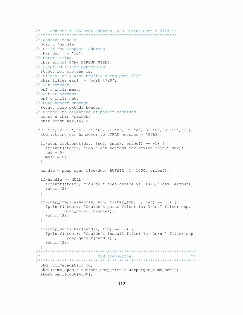
112
/* IP Address = LOOPBACK Address, UPD Listen Port = 4729 */ /*********************************************************/ // Session handle pcap_t *handle; // Sniff the Loopback Address char dev[] = “lo”; // Error string char errbuf[PCAP_ERRBUF_SIZE]; // Compiled filter expression struct bpf_program fp; // Filter, only what traffic using port 4729 char filter_exp[] = “port 4729”; // Our netmask bpf_u_int32 mask; // Our IP Address bpf_u_int32 net; // PCAP header storage struct pcap_pkthdr header; // Pointer to beginning of packet received const u_char *packet; char const hex[16] = {‘0’,’1’,’2’,’3’,’4’,’5’,’6’,’7’,’8’,’9’,’A’,’B’,’C’,’D’,’E’,’F’}; std::string gsm_handover_to_UTRAN_message = “0663”; if(pcap_lookupnet(dev, &net, &mask, errbuf) == -1) { fprintf(stderr, “Can’t get netmask for device %s\n,” dev); net = 0; mask = 0; } handle = pcap_open_live(dev, BUFSIZ, 1, 1000, errbuf); if(handle == NULL) { fprintf(stderr, “Couldn’t open device %s: %s\n,” dev, errbuf); return(2); } if(pcap_compile(handle, &fp, filter_exp, 0, net) == -1) { fprintf(stderr, “Couldn’t parse filter %s: %s\n,” filter_exp, pcap_geterr(handle)); return(2); } if(pcap_setfilter(handle, &fp) == -1) { fprintf(stderr, “Couldn’t install filter %s: %s\n,” filter_exp, pcap_geterr(handle)); return(2); } /*****************************************************************/ /* GSM Transmitter */ /*****************************************************************/ uhd::tx_metadata_t md; uhd::time_spec_t current_usrp_time = usrp->get_time_now(); short smpls_out[4680];
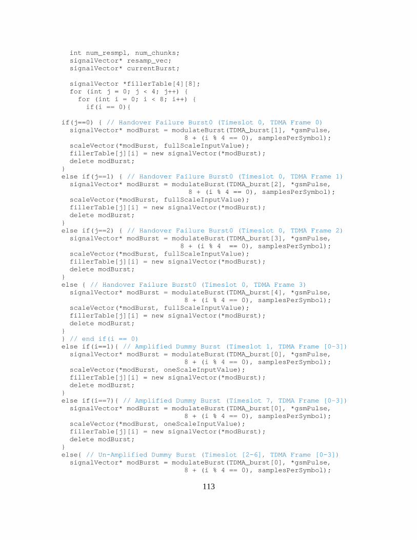
113
int num_resmpl, num_chunks; signalVector* resamp_vec; signalVector* currentBurst; signalVector *fillerTable[4][8]; for (int j = 0; j < 4; j++) { for (int i = 0; i < 8; i++) { if(i == 0){ if(j==0) { // Handover Failure Burst0 (Timeslot 0, TDMA Frame 0) signalVector* modBurst = modulateBurst(TDMA_burst[1], *gsmPulse, 8 + (i % 4 == 0), samplesPerSymbol); scaleVector(*modBurst, fullScaleInputValue); fillerTable[j][i] = new signalVector(*modBurst); delete modBurst; } else if(j==1) { // Handover Failure Burst0 (Timeslot 0, TDMA Frame 1) signalVector* modBurst = modulateBurst(TDMA_burst[2], *gsmPulse, 8 + (i % 4 == 0), samplesPerSymbol); scaleVector(*modBurst, fullScaleInputValue); fillerTable[j][i] = new signalVector(*modBurst); delete modBurst; } else if(j==2) { // Handover Failure Burst0 (Timeslot 0, TDMA Frame 2) signalVector* modBurst = modulateBurst(TDMA_burst[3], *gsmPulse, 8 + (i % 4 == 0), samplesPerSymbol); scaleVector(*modBurst, fullScaleInputValue); fillerTable[j][i] = new signalVector(*modBurst); delete modBurst; } else { // Handover Failure Burst0 (Timeslot 0, TDMA Frame 3) signalVector* modBurst = modulateBurst(TDMA_burst[4], *gsmPulse, 8 + (i % 4 == 0), samplesPerSymbol); scaleVector(*modBurst, fullScaleInputValue); fillerTable[j][i] = new signalVector(*modBurst); delete modBurst; } } // end if(i == 0) else if(i==1){ // Amplified Dummy Burst (Timeslot 1, TDMA Frame [0–3]) signalVector* modBurst = modulateBurst(TDMA_burst[0], *gsmPulse, 8 + (i % 4 == 0), samplesPerSymbol); scaleVector(*modBurst, oneScaleInputValue); fillerTable[j][i] = new signalVector(*modBurst); delete modBurst; } else if(i==7){ // Amplified Dummy Burst (Timeslot 7, TDMA Frame [0–3]) signalVector* modBurst = modulateBurst(TDMA_burst[0], *gsmPulse, 8 + (i % 4 == 0), samplesPerSymbol); scaleVector(*modBurst, oneScaleInputValue); fillerTable[j][i] = new signalVector(*modBurst); delete modBurst; } else{ // Un-Amplified Dummy Burst (Timeslot [2–6], TDMA Frame [0–3]) signalVector* modBurst = modulateBurst(TDMA_burst[0], *gsmPulse, 8 + (i % 4 == 0), samplesPerSymbol);

114
scaleVector(*modBurst, zeroScaleInputValue); fillerTable[j][i] = new signalVector(*modBurst); delete modBurst; } } // end inner for loop } // end outer for loop md.start_of_burst = false; md.end_of_burst = false; md.has_time_spec = false; for(;;){ std::string str; packet = pcap_next(handle, &header); if(packet == NULL){ continue; } for(int i = 0; i<header.len; i++) { const char ch = packet[i]; str.append(&hex[(ch & 0xF0) >> 4], 1); str.append(&hex[(ch & 0xF)], 1); } std::string gsm_message; gsm_message.append(str.begin()+122,str.begin()+126); if(gsm_message == gsm_test_message){ std::cout << “Recieved Handover to UTRAN Message” << std::endl; break; } } // Set initial usrp time usrp->set_time_now(uhd::time_spec_t(0.0)); /********************************************************************/ /* Set a wait time between receiving handover to UTRAN message */ /* and sending handover failure message so bursts arrive in correct */ /* timeslot of SDCCH. */ /********************************************************************/ boost::this_thread::sleep( boost::posix_time::milliseconds(38) ); for(int j=0; j<4; j++){ for(int i=0; i<8; i++){ signalVector* currentBurst = fillerTable[j][i]; tx_vec = concat(tx_vec, currentBurst); num_chunks = tx_vec->size() / 585; if (num_chunks < 1){ //std::cout << “need more samples” << std::endl; } else { // Re-sampler needs four GSM bursts before resampling process can start resamp_vec = resmpl_sigvec(tx_hist, &tx_vec, tx_lpf, 96, 65, 585);
115
// Conversion of re-sampled vector from float to short num_resmpl = sigvec_to_short(resamp_vec, smpls_out); // Send re-sampled burst of type short to USRP size_t num_tx_samps = tx_stream->send(smpls_out + 192 * 2, num_resmpl - 192 , md, uhd::device::SEND_MODE_FULL_BUFF); } // end else } // end inner for } // end outer for /*********************************************************************/ /*Delete Vectors, Destroy Signal Processing Library, and Cleanup PCAP*/ /*********************************************************************/ pcap_freecode(&fp); pcap_close(handle); delete tx_hist; delete tx_lpf; delete tx_vec; delete gsmPulse; sigProcLibDestroy(); std::cout << “TRANSMIT SUCCESS” << std::endl; return EXIT_SUCCESS; } // end main loop

116
THIS PAGE INTENTIONALLY LEFT BLANK
117
LIST OF REFERENCES
[1] D. Burgess, H. Samra, R. Sevlian, A. Levy, and P. Thompson. (2013). OpenBTS public release [Online software]. Available: http://wush.net/svn/range/software/public
[2] P. Krysik. (2013). Airprobe [Online software]. Available:
https://svn.berlin.ccc.de/projects/airprobe [3] E. Blossom, M. Ettus, T. Rondeau, and J. Blum. (2013). GNURadio [Online
software]. Available: http://www.gnuradio.org [4] E. Southern, A. Ouda, and A. Shami, “Solutions to security issues with legacy
integration of GSM into UMTS,” International Conference for Internet Technology and Secured Transactions, pp. 614–619, Dec. 11–14, 2011.
[5] U. Meyer and S. Wetzel, “On the impact of GSM encryption and man-in-the-
middle attacks on the security of interoperating GSM/UMTS networks,” International Symposium on Personal, Indoor and Mobile Radio Communications, vol. 4, pp. 2876–2883, Sept. 5–8, 2004.
[6] P. Ekdahl and T. Johansson, “Another attack on A5/1,” IEEE Trans. Information
Theory, vol. 49, no. 1, pp. 284–289, Jan. 2003. [7] 3rd Generation Partnership Project Radio Resource Control Protocol Technical
Specification, 3GPP TS 44.018 (Release 11), 2012. [8] 3rd Generation Partnership Project Mobile Radio Interface Layer 3 Technical
Specification, 3GPP TS 44.118 (Release 11), 2012. [9] 3rd Generation Partnership Project Mobile Radio Interface Layer 3 Technical
Specification, 3GPP TS 04.18 (Release 99), 2006. [10] 3rd Generation Partnership Project Modulation Technical Specification, 3GPP
TS 05.04 (Release 99), 2001. [11] 3rd Generation Partnership Project Multiplexing and Multiple Access on the
Radio Path Technical Specification, 3GPP TS 05.02 (Release 99), 2003. [12] 3rd Generation Partnership Project Channel Coding Technical Specification,
3GPP TS 05.03 (Release 99), 2005. [13] 3rd Generation Partnership Project Data Link Layer Technical Specification,
3GPP TS 44.006 (Release 11), 2012.
118
[14] L. Perkov, A. Klisura, and N. Pavkovic, “Recent advances in GSM insecurities,”
Proceedings of the 34th International Convention, pp. 1502–1506, May 23–27, 2011.
[15] I. Briceno, M. Goldberg, and D. Wagner, (2013, Oct.). A pedagogical
implementation of A5/1 [Online]. Available: http://www.scard.org/gsm/a51.html [16] 3rd Generation Partnership Project UTRAN Functions and Examples on
Signaling Procedures Technical Report, 3GPP TR 25.931: (Release 11), 2012. [17] G. Alsenmyr, J. Bergstrom, M. Hagberg, A. Milen, W. Muller, H. Palm, H.
Velde, P. Wallentin, and F. Wallgren, “Handover between WCDMA and GSM,” Ericsson Review, vol. 80, no. 1, pp. 6–11, 2003.
[18] A. Mohammed, H. Kamal, and S. AbdelWahab, “2G/3G Inter-RAT Handover
Performance Analysis,” Second European Conference on Antennas and Propagation, pp. 1, 8, 11–16, Nov. 2007.
[19] J. Eberspächer, H. Vögel, C. Bettstetter, and C. Hartmann, GSM Architecture,
Protocols and Services, 3rd ed. West Sussex, United Kingdom: John Wiley & Sons Ltd, 2009.
[20] S. K. Das, Mobile Handset Design, Singapore: John Wiley & Sons (Asia) Pte Ltd,
2010. [21] Ettus Research. (2013, Oct.). USRP N200/N210 networked series specifications
[Online]. Available: http//www.ettus.com [22] D. Shen. (2013). Tutorial 4: The USRP board [Online]. Available:
http://radioware.nd.edu/documentation/hardware/the-usrp-board [23] National Instruments. (2013, Mar.). An Introduction to software defined radio
with NI LabVIEW and NI USRP [Online]. Available: ftp://ftp.ni.com/pub/events/campus_workshop/niusrp_hands_on_student_manual.pdf
[24] T. Engel. (2013). Xgoldmon [Online software]. Available:
https://github.com/2b-as/xgoldmon

119
INITIAL DISTRIBUTION LIST
1. Defense Technical Information Center Ft. Belvoir, Virginia 2. Dudley Knox Library Naval Postgraduate School Monterey, California


![[eBook] OpenBTS Guide](https://img.pdfslide.net/doc/110x75/55cf9463550346f57ba1abfd/ebook-openbts-guide.jpg)