Embed Size (px)
Citation preview

Falcon 4 Navigation charts tutorial Rev 1.03
Last Reviewed: 6th Nov 2006 11:20Z
Falcon 4 Navigation charts Tutorial. 1
Navigation Chart Tutorial
Rev 1.03 Nov 6th 2006
Olivier “Red Dog”Beaumont

Falcon 4 Navigation charts tutorial Rev 1.03
Last Reviewed: 6th Nov 2006 11:20Z
Falcon 4 Navigation charts Tutorial. 2
Content Navigation Chart Tutorial....................................................................................... 1 1. Introduction..................................................................................................... 3 2. Basic Radio Navigation in Falcon. ........................................................................ 5
2.1. Tacan mechanisation .............................................................................. 7 2.2. Setting up the cockpit .............................................................................. 9 2.3. The main navigation instrument: the HSI.................................................. 11 2.4. How to intercept a radial. ....................................................................... 16 2.5. Tracking a radial once established ........................................................... 24 2.6. What about the wind ? ........................................................................... 25 2.7. Station passage. ................................................................................... 25 2.8. IFR instrument scanning......................................................................... 26 2.9. Things to remember. ............................................................................. 27
3. Advanced Radio Navigation in Falcon................................................................. 28 3.1 Following the ILS to the minima. .............................................................. 29 3.2. DME ARC ............................................................................................. 32 3.3. Tacan approach .................................................................................... 34 3.4. Holding procedures................................................................................ 36
3.4.1 Direct Entry..................................................................................... 38 3.4.2 Teardrop Entry................................................................................. 39
3.4.3 Parallel Entry ................................................................................... 40 3.5. Circle to land ........................................................................................ 41
4. Navigation charts Review................................................................................. 43 4.1 Airport Diagram charts ............................................................................ 45 4.2 Approach charts ..................................................................................... 49
4.2.1. Titles ............................................................................................. 52 4.2.2. Header: ......................................................................................... 52 4.2.3. Plan view. ...................................................................................... 55 4.2.4. Side view ....................................................................................... 66 4.2.5. Minimum........................................................................................ 68
4.3 Departure charts (SID)............................................................................ 69 4.3.1. SID Review .................................................................................... 71
4.4 Special charts ........................................................................................ 75
5. A full training flight around Kimpo airport using the charts.................................... 82 5.1. Flight planning....................................................................................... 83 5.2. Starting engine...................................................................................... 87 5.3. Flying the SID ....................................................................................... 89 5.4. Transition to normal flight ....................................................................... 92 5.5. The approach ........................................................................................ 93 5.6. Let’s make another one........................................................................... 97 5.7. Conclusions......................................................................................... 103 6. List of abbreviations used. ............................................................................. 104 7. Credits and sources ...................................................................................... 107

Falcon 4 Navigation charts tutorial Rev 1.03
Last Reviewed: 6th Nov 2006 11:20Z
Falcon 4 Navigation charts Tutorial. 3
1. Introduction

Falcon 4 Navigation charts tutorial Rev 1.03
Last Reviewed: 6th Nov 2006 11:20Z
Falcon 4 Navigation charts Tutorial. 4
The purpose of this tutorial is to document the Falcon 4 navigation charts I have been creating for the past 2 years. Those charts refer to specific symbols, abbreviation and IFR (Instrument Flight Rules) procedures that the average F4 flyer might not be current with. Let’s try to clear it up a little. First, let me stress the point that I’m not in any way a specialist of the matter. I’m just an IFR freak, flying flight sims for more than a decade (geez I could almost say two decades!), especially IFR flight sims like Elite or alike. So my experience and knowledge is pretty limited and I am responsible for any mistake in this document – You have been warned, it’s not a tutorial about real life IFR flying – just the way I do it in Falcon. Now, F4 is very far from being an IFR flight sim, but since BMS1.3, we had some nice weather effect (unfortunately taken back since) but the idea was appealing to me and I decided to press further by doing a chart set for each South Korean airbase. I took the liberty to take some distances from real life IFR procedure to adapt them to Falcon. And you will certainly notice that most of the mentioned procedures comes from the civil side of aviation, I am perfectly aware that fighter pilots may not loose their time flying such procedures, but it’s the best I got to base the Falcon charts on. Beside the weather aspect, the idea was also to give reference points to members of the same multiplayer flights by naming (and giving relevant F4 GPS coordinates) specific waypoints around the airports. The purpose here is obvious. Each member would follow the published route alone and rendezvous with the other member of the flight by holding at a certain point. And finally, the lack of decent ATC in Falcon can also be avoided by following the charts. It’s even possible to assign a human controller in multiplayer to act as ATC and vectors the flight around the airports, completely bypassing the original ATC. You have it figured out by now; most of what will be explained might be relevant to human flights only. There is no way at this time that the AI controlled flights or the AI ATC might play the charts game. Meanwhile, having one AI wingman doesn’t really complicate the problem if you make it stick your wing closely (otherwise, it will turn around you in circle keeping his speed up). The other annoying aspect will be the Falcon ATC, but as you will see, there are workarounds and at worst it can be completely ignored. The best solution is when multiplayer squadron assign a human flight controller who endorses the charts. That what we are putting in place in our squadron and it works pretty well. The charts were created with a BMS based version of old Falcon with Baz-T elevation patch. But they should be compliant to any F4 flavours – even with F4AF. Although Leadpursuit seems to change their tacan channels with each new patch. And I don’t want to keep track of those futile changes. So you might need to change the tacan channel but the procedures remain valid. Disclaimer: It took me about 2 years to create a chart set for each South Korean airbase. It is obvious that during that time, my experience and my way of viewing things changed a little. Add to that the Falcon code changed as well… As a consequence some early charts are quite different from late charts. Beside while writing this document, I realized some charts had errors needing correction. This will be done but probably one at a time, depending on my availability for such a task.

Falcon 4 Navigation charts tutorial Rev 1.03
Last Reviewed: 6th Nov 2006 11:20Z
Falcon 4 Navigation charts Tutorial. 5
2. Basic Radio Navigation in Falcon.

Falcon 4 Navigation charts tutorial Rev 1.03
Last Reviewed: 6th Nov 2006 11:20Z
Falcon 4 Navigation charts Tutorial. 6
We can’t really hope to explain how to use the charts in Falcon without talking a little bit about radio navigation, can we? Radio navigation is a very vast subject and there are publications and tutorials available on the web to learn how to master IFR flights. One of the best resources for us is the lessons in Microsoft Flight Simulator. There are also a lot of Jepessen publications very useful. (See sources …) Opposed to VFR (Visual Flight Rules), IFR (Instrument Flight Rules) use radio beacons aids and allow the pilots to fly without any visual reference. In real life, there are quite a few different beacons:
• NDB: Non Directional Beacon • VOR: VHF Omni Directional Range • DME: Distance measuring equipment • VORDME: beacon combining the VOR and the DME. • TACAN: TACtical Air Navigation system. • ILS: Instrument Landing System
…. Falcon supports only TACANs and a pseudo ILS system. With the downside that ILS are collocated with a tacan and tacan stations can only be collocated to an airbase. It’s often the case in reality as well. But some radio-navigation aids can be placed outside of the airbase perimeters and act as stand alone beacons. In Falcon, implementing those is possible as well by using an INS steerpoint but we will come back to this later on. For Falcon, we will consider the TACAN as a VORDME: A beacon emitting in all directions (360°) with a fixed range and a distance measuring capability. In the cockpit, we read the Tacan information through the HSI Instrument.
Falcon 4 Navigation charts tutorial Rev 1.03
Last Reviewed: 6th Nov 2006 11:20Z
Falcon 4 Navigation charts Tutorial. 7
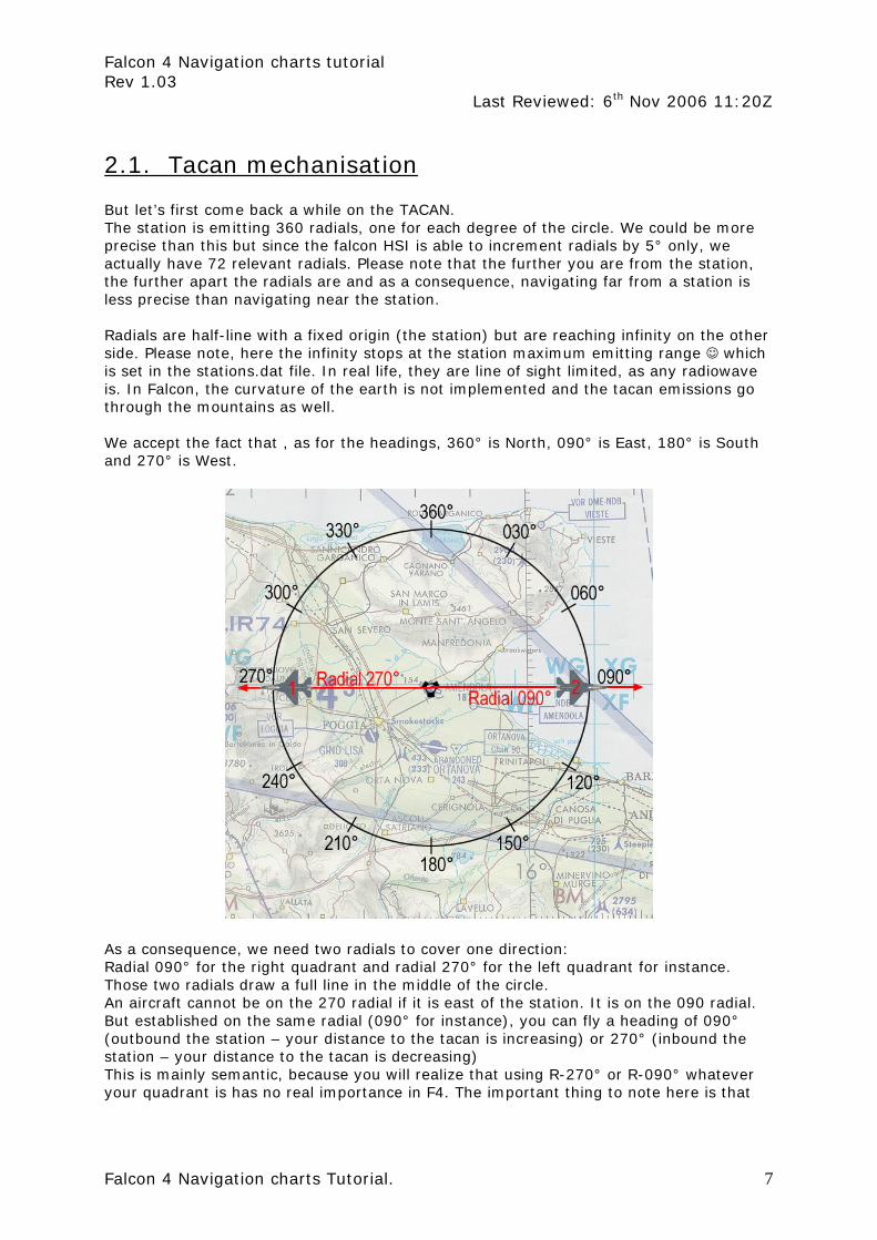
2.1. Tacan mechanisation But let’s first come back a while on the TACAN. The station is emitting 360 radials, one for each degree of the circle. We could be more precise than this but since the falcon HSI is able to increment radials by 5° only, we actually have 72 relevant radials. Please note that the further you are from the station, the further apart the radials are and as a consequence, navigating far from a station is less precise than navigating near the station. Radials are half-line with a fixed origin (the station) but are reaching infinity on the other side. Please note, here the infinity stops at the station maximum emitting range ☺ which is set in the stations.dat file. In real life, they are line of sight limited, as any radiowave is. In Falcon, the curvature of the earth is not implemented and the tacan emissions go through the mountains as well. We accept the fact that , as for the headings, 360° is North, 090° is East, 180° is South and 270° is West.
As a consequence, we need two radials to cover one direction: Radial 090° for the right quadrant and radial 270° for the left quadrant for instance. Those two radials draw a full line in the middle of the circle. An aircraft cannot be on the 270 radial if it is east of the station. It is on the 090 radial. But established on the same radial (090° for instance), you can fly a heading of 090° (outbound the station – your distance to the tacan is increasing) or 270° (inbound the station – your distance to the tacan is decreasing) This is mainly semantic, because you will realize that using R-270° or R-090° whatever your quadrant is has no real importance in F4. The important thing to note here is that

Falcon 4 Navigation charts tutorial Rev 1.03
Last Reviewed: 6th Nov 2006 11:20Z
Falcon 4 Navigation charts Tutorial. 8
when you talk to somebody, being a wingman or ATC, you need to stay coherent and use the correct terminology. So even if you are flying a heading of 270° to the station but you’re still east of the station, you need to state that you are on the 090 radial inbound the station. I know this is probably confusing at this time, but read on. Tacans also have a distance measuring equipment (DME) that gives the distance in Nautical Miles (Nm) between your aircraft and the selected station. That indication is given in the top left window labelled “miles” in the HSI. There is a maximum distance at which the tacan is emitting according to different parametres in real life. In Falcon, the range varies between 25Nm and 150Nm. Past that distance, the HSI will be flagged with large red indicators to notify the pilot that the data received are not useable. See the HSI description further down for more information.

Falcon 4 Navigation charts tutorial Rev 1.03
Last Reviewed: 6th Nov 2006 11:20Z
Falcon 4 Navigation charts Tutorial. 9
2.2. Setting up the cockpit Obviously, the fist thing you’d need to do is to set the correct information in the system. Tacan channel, tacan band etc. With the original Falcon, we only had access to the BACKUP navigation system of the F-16. With current versions however we now have access to both the backup system and the “normal” system. I mention it because I know a lot of you still use the old backup system while you should really start learning how to use the UFC to set all the navigation data in the cockpit. The backup system is implemented on the AUX-COMM cockpit panel. When the CNI
switch is in the backup position – tacan channels and band are to be inputted from this very panel by clicking the channel numbers and X or Y band. You also need to specify if you will track a ground station or an airborne station. That is done with the T/R or A/A TR switch. The A/A TR being for airborne emitters like the tankers. Now again, it’s not the correct way to do it, it’s a backup way only used when the main system is inop.
The correct system to input the tacan channel and band into the cockpit is trough the Up Front Controller (UFC) by using the ICP and the DED. For that to work, obviously the CNI switch of the AUX COMM panel needs to be placed in the UFC position, but that’s an item required to be done at the ramp start (see checklists). Depress the T-ILS button #1 of the ICP to enter the Tacan/ILS page of the DED:
The tacan channel can then be typed in the scratchpad by using the ICP buttons. First check that the asterisks are correctly placed around the scratchpad (DCS up or down if necessary) and depress the ICP numeric keys 5 and 4 then the ENTER key supposing you

Falcon 4 Navigation charts tutorial Rev 1.03
Last Reviewed: 6th Nov 2006 11:20Z
Falcon 4 Navigation charts Tutorial. 10
want to input Amendola AB tacan channel. In the example below, the picture on the left shows the T-ILS page with a 118Y AA tacan selected.
Next is to set the correct band. In F4, we have the X band (for ground) and Y band (for air). Strictly speaking it’s not 100% accurate, but it’s the way it’s supposed to work in F4. To change the band, simply input “0” (zero) in the scratchpad and press ENTER. That will toggle the band from Y to X to Y … (see figure above right) The last thing you need to set as the tacan is concerned is the T/R or A/A TR. That is done by depressing the DCS switch to the right (SEQ position). The value will toggle from T/R to A/A TR and back. Okay; the basic steps are done. Now is a great time to introduce the main navigation instrument of the F-16 cockpit: the Horizontal Situation Indicator. Well a note of warning first. When you’re simply following your pre planned route, your main instrument will of course be the MFD on the HSD page. But when you will be doing radio-navigation relative to a steerpoint or a tacan station, you will need to use the HSI. Before giving a rundown of the instrument purpose, you need to know that the HSI has 4 different working modes. Those modes are set on the small panel just left of the HSI:
TCN MODE: The instrument uses the set tacan station as a reference and gives bearing and distance relative to that station. TCN/ILS MODE: Same as above but gives steering cues for the Tacan collocated ILS. NAV MODE: The HSI in this case will not use a radio-navigation station as a reference but the currently selected INS steerpoint. That is very handy when you want to navigate to a waypoint and arriving with a set heading. In this mode, the steerpoint is considered a virtual tacan. NAV/ILS MODE: same as above but providing ILS steering cues at the same time. That position will be used for instance when returning at the pre-planned airbase and shooting an ILS approach. Note that both ILS position are not really implemented correctly since
the ILS in Falcon is tied to the Tacan (depending on the Falcon version) which is obviously not the case in the real life.

Falcon 4 Navigation charts tutorial Rev 1.03
Last Reviewed: 6th Nov 2006 11:20Z
Falcon 4 Navigation charts Tutorial. 11
2.3. The main navigation instrument: the HSI. Still there? Perfect. Let’s move on to the main course, the Horizontal Situation Indicator.
The instrument gives you a god’s eye view of your aircraft (in the centre of the instrument) and its position relative to the selected reference (radio-navigation station in TCN mode or Steerpoint in NAV mode)
• The Heading tape: Gives your heading on the 12 o’clock position. • The DME window: Gives the slant range between you and the selected station. • The Course window: Gives the currently selected radial. • The Course knob: Set the desired radial • The Heading knob: Allow to set the heading bug on a selected heading. • The Course arrow: points to the selected course on the heading tape. • The CDI (Course Deviation Indicator): Gives the position of the selected radial
relative to the position of your aircraft. • Station bearing pointer: Points directly to the selected station. This arrow is really
interesting both for the beginner and the advanced user. Firstly it clearly gives the bearing to the station and for the most advanced user it can be used as an ADF (Automatic Direction Finder) able to track a virtual NDB. More on this later.
• Station bearing pointer tail: That’s the tail of the red pointer, giving the reciprocal heading of the station bearing.
• To/From indicator: For reasons I will explain later, the TO/FROM is not to be used in Falcon. It’s bugged in most of the Falcon version.
• Heading Bug: Moves accordingly to the HDG knob. It’s a reference heading that is used by the autopilot system in ROLL HDG SEL mode. It can also be used as a reminder of headings (wind corrections, …) when you don’t use the autopilot.
Let’s start with a simple ☺ example, Taking fig1 above:

Falcon 4 Navigation charts tutorial Rev 1.03
Last Reviewed: 6th Nov 2006 11:20Z
Falcon 4 Navigation charts Tutorial. 12
The airplane #2 is on the 090 radial. But the HSI can display two readings, depending which radial is selected: First, notice that the actual heading is 090°, since you see the position of AC#2 on fig1; you know the aircraft is EAST of the station and is going away. We say it’s OUTBOUND. The station bearing pointer points at 6 o’clock, meaning the station is right behind AC#2. The set course is 090 and the course arrow is aligned with the 090° on the heading tape. The CDI is centred; meaning AC#2 is spot on the radial. If the pilot were to continue flying on the
090° heading (considering a no wind condition) the aircraft would continue flying away from the station established on the 090° radial. The second picture on the left is taken at exactly the same moment (please forget the DME reading that has increased – the sim was not freezed ☺ ) but this time the course 270° has been selected. The aircraft is still on a 090° heading OUTBOUND the station. The Course arrow points at the 270° mark on the heading tape and the CDI is centred, meaning we are still on the 090° radial. This is where which radial you are on gets tricky ! Obviously, it is easier to radio-navigate with option 1 when the course arrow is pointing to the actual
heading. So you will want to align as much as possible the Course arrow with the actual heading to avoid thinking about reciprocal radials. In case of option 1 above, it is clear
AC#2 – Option 1 : Set R-090°
AC#2 – Option 2 : Set R-270°

Falcon 4 Navigation charts tutorial Rev 1.03
Last Reviewed: 6th Nov 2006 11:20Z
Falcon 4 Navigation charts Tutorial. 13
we want to fly outbound using the 090° radial. Because first, we are flying outbound and secondly we are indeed on the radial 090°. Notice the TO/FROM indicator. On the first picture it is on the right side of the course arrow and it points up, meaning the Falcon code is trying to make us believe we are in TO. This is highly inacurrate since it should point downward as we are in FROM. Indeed, the station is behind us and we are moving away from it. On the second picture, it is on the left side of the course arrow and it points down, meaning we are in FROM this time But we haven’t changed course, so why does the TO/FROM indicator give contradictory information? There has been a bug with this TO/FROM indicator since day one of Falcon and unfortunately it has never been corrected because there was always something more important to do. Which has always been correct ☺). [edit: since this was written the bug was finally squashed in OF but remain in other versions: FF, AF, SPx,…] Let’s take the indicator from FS2004 for instance, on the same situation:
We are flying a beech baron established on Radial 090° from a VORDME. The RMI is set to 090° as indicated by the course arrow and we are on the radial, as indicated by the centred CDI. Now look at the TO/FROM indicator which in this case is white… it points backwards, meaning we are FROM the station. This is what the F4 HSI should display in the above example. Now let’s turn the Course knob to select R-270 on the RMI and see what happens with the TO/FROM indicator. If it were to work as in Falcon (unlikely) it would rotate with the course arrow and finally points UP once the radial 270 is set which would be highly incorrect. Now what really happens is that, the TO/FROM indicator rotates with the course arrow but it changes its state at the 360° mark (actually 90° off the selected radial) and continue its rotation until R270° is set where it points downward as it should. See the two pictures on the left. As you see in both images, taken at the same moment but with a different radial selected, the TO_FROM indicator remains coherent and correctly indicates the FROM state we are in. This is how the F4 HSI should work as well. Unfortunately, the F4 TO/FROM indicator always is completely useless in F4. So don’t use it at all. I will refer to INBOUND and OUTBOUND course instead in this document.

Falcon 4 Navigation charts tutorial Rev 1.03
Last Reviewed: 6th Nov 2006 11:20Z
Falcon 4 Navigation charts Tutorial. 14
Let’s go back to Falcon by considering the following example: AC#3 is on the WEST of the station and is flying toward the station with an actual heading of 090°. It’s actually on the 270° radial. But it will be easier to use the 090° course in the HSI because the reading will be clearer. Indeed, if we select course 090° in the HSI, the course arrow points at the 12 o’clock position and is the same as the heading – as pictured below. On the contrary, if course 270° is set, the course arrow points at the 6 o’clock position and although it is more correct, it’s not easier to work with.
As a conclusion, even though the radials are half-line with a fixed origin, it’s always better to use the radial pointing at the heading as long as you always keep in mind the true radial you are on. So far, we have been considering very easy cases where the aircraft is already tracking a radial – with the CDI centred – it is called ‘tracking’ a radial and it’s the easy part. The hard part happens before that stage when the pilot tries to intercept the desired radial. Initially, when the pilot sets the required radial in the HSI, he gets something like this:
So what does the instrument tell us? 1. The tacan is somewhere behind on the right
hand side. On the 230° bearing. So we are going away from the station
2. The selected course is 090° 3. The 090° radial is on my right (CDI is offset
to the right) So we are LEFT of course. 4. I’m flying on a 112° heading 5. The station is at 2 Nm from me. 6. Anything else? Yes: discard the TO/FROM
indicator ☺

Falcon 4 Navigation charts tutorial Rev 1.03
Last Reviewed: 6th Nov 2006 11:20Z
Falcon 4 Navigation charts Tutorial. 15
With a little experience, you will have a rather good idea of your position in space relative to the station. If it’s clear for you, go direct to the next section. If not, read on… A good trick to visualize in space your position before starting a radial interception is to centre the CDI by turning the CRS knob. Once the CDI is centred, you know for sure on which radial you currently are… Bear in mind that the CDI will be centred on two reciprocal radials (310° and 130° for instance) and that you are usually moving at high speed in your F-16 and the CDI may not remain centred for long. The picture above was taken on the threshold of Amendola runway 11. Let’s centre the CDI to check the radial we are on:
We are on R-135 (reciprocal is R-315°) Knowing that information, you know you are somewhere on a line originating at the station and extending on the 135° direction. The DME indication gives you the distance to the station, fixing the point on that imaginary line where you exactly are. You will have understood it, to succeed in correctly intercepting a radial; you first need to know exactly where you are relative to the emitting station, hence the relevant radial.

Falcon 4 Navigation charts tutorial Rev 1.03
Last Reviewed: 6th Nov 2006 11:20Z
Falcon 4 Navigation charts Tutorial. 16
2.4. How to intercept a radial. Once you know where you are and you know which radial you need to intercept, you need to fly towards the imaginative line drawn in space by the radial. The shortest route to that interception point is to fly a heading at 90° from that line. With such a perpendicular heading, you will reach the radial very fast but you will have lots of difficulties to make a smooth interception because the CDI will pass from one side to the other very fast. Let’s consider the following example:
We have to intercept R-035° outbound Amendola tacan. We are on the ground, ready to take-off on RWY 29 and once airborne, we will make a right turn to heading 310° as the procedure implies. Once we flew away a little from the airbase, we will make a large 180° to the right and attack the radial with a 90° angle and see what happens on point 1, 2 and 3. The HSI is in tacan mode, radial set to 035° and we are rolling on the runway.

Falcon 4 Navigation charts tutorial Rev 1.03
Last Reviewed: 6th Nov 2006 11:20Z
Falcon 4 Navigation charts Tutorial. 17
At point 1, we show a 90° attack angle (A) on the 035° radial. The “A” angle is clearly pictured on the HSI by the angle created by the actual heading (125°) and the set course (035°). Note the position of the station bearing pointer. As you are nearing the radial, it will descend to the 215° mark that will be reached when the radial is intercepted.
Nearing the radial, the CDI will start to move towards the centre of the dial. The greatest the interception angle, the fastest the CDI will move. When the CDI is centred with the yellow arrow, it means you are spot on the radial. That is point 2. Note that the course arrow points to the left, meaning that the 035° radial extend to the left side. So if you were to intercept it OUTBOUND, you should turn LEFT. If you were to intercept it INBOUND, you should turn RIGHT, towards the tail of the arrow, or toward the station bearing pointer.
Now of course you are flying a 125° heading, so you’re just a fraction of a second on the radial. After that time, the CDI will start to move on the other side of the course arrow. You have just passed the radial and are now on the other side. That is position #3. Notice the station bearing pointer that continue its progression past 215° now that you overshot the radial. Notice that according to your distance to the station, the amount of time it takes the needle to swing from one side to the other will be different. Really fast at close range, slower but still faster
than desired due to the 90 intercept at longer ranges Fine, you probably have it figured out by now; intercepting a radial with a 90° attack angle won’t provide a smooth ride. But who cares? You don’t have passengers – do you? The guy in the back you say – don’t worry about him, he likes being bounced on the canopy.

Falcon 4 Navigation charts tutorial Rev 1.03
Last Reviewed: 6th Nov 2006 11:20Z
Falcon 4 Navigation charts Tutorial. 18
In general aviation, they teach you to intercept a radial with a 30° attack angle. That indeed will provide plenty of time for the pilot to see the CDI start moving towards the centre and the final turn will be smooth: Here’s how it’s done still using the same example:
After taking off from runway 29, we turn right to a heading of 065° to have a 30° interception angle on the 035° radial. As before, that interception angle is perfectly visible on the HSI as pictured on the left. At position 1, the CDI is offset to the right (meaning the set radial is on your right side) and will start to move slowly towards the centre of the dial as we near the imaginary line.

Falcon 4 Navigation charts tutorial Rev 1.03
Last Reviewed: 6th Nov 2006 11:20Z
Falcon 4 Navigation charts Tutorial. 19
At point 2, the CDI is centred and we turn to follow the radial on a heading of 035°. Notice, I already started a gentle turn to the left to intercept. If you delay your turn too long, you run the risk of overshooting the interception and fly parallel to the radial right next to it. You would have then to restart a smooth interception to get back on the correct route. At 13 DME and with such a small interception angle, the CDI moves very slowly giving you plenty of time to intercept smoothly.
Here’s the instrument view at point 3. We are going away from the tacan, aligned on the 035° radial. The station bearing pointer shows the tacan right behind us, confirming the fact that we are outbound. In a no wind situation, we would remain on the radial and the CDI would remain aligned with the course arrow. In a windy situation, you might drift off the radial and might need to start compensating for wind drift with a small correction angle.
Of course, the situation is a little bit more dynamic than explained on paper. Once the CDI starts to move toward the course arrow, you will need to be ready to turn. You might also turn a little; say by 10° increment, to slow the CDI progression toward the centre. That will give you more time and will flatten the final interception turn and decrease the risks of overshooting the radial. With a little experience, you will increase your interception angle; according to the distance you are from the station (the closer you are, the faster the interception will occur) and smooth it on the run to fly a curved interception on the radial, finishing your turn correctly aligned.

Falcon 4 Navigation charts tutorial Rev 1.03
Last Reviewed: 6th Nov 2006 11:20Z
Falcon 4 Navigation charts Tutorial. 20
Personally, in Falcon, I tend to use a 45° interception angle and decrease the angle a little once the CDI is one dot from the centre.
As I mentioned above, when you are very far from the radio navigation station, you might want to start your interception with a rather large angle to ensure that you do not go too far away especially when intercepting outbound. (Tacans in F4 have a limited range, remember?) So start with a 90° intercept angle and decrease your angle once you near the radial. Bear in mind the distance to the station also when deciding an intercept angle! A very good tip here is to use the station bearing pointer. Indeed, you know it points directly to the station, so when the bearing pointer start to move toward the course arrow (or the end of the course arrow when intercepting outbound – you know the radial is nearing, even before the CDI starts to move. That indication is good information to help you decide what interception angle to use. Consider again the following images and concentrate on the red bearing pointer:

Falcon 4 Navigation charts tutorial Rev 1.03
Last Reviewed: 6th Nov 2006 11:20Z
Falcon 4 Navigation charts Tutorial. 21
The example is the same as the 90° interception above. The important thing here to visualize is the progression of the red bearing pointer starting at the 1 o’clock position and descending to the 5 o’clock position. As you know the red arrow points to the selected station and as you are nearing radial 090°, the pointer will move toward the course arrow (point or tail depending if the radial you set is outbound or inbound). When you are on the radial, the pointer will be aligned with the yellow line (right picture of the middle row). As we are just passing the radial in this example, the pointer continue drifting downwards as the tacan goes to our right rear quadrant. The bearing pointer is a very helpful instrument to help you visualize your position in space relative to an emitter, which is after all the goal of radio navigation. Don’t hesitate to use it.
Falcon 4 Navigation charts tutorial Rev 1.03
Last Reviewed: 6th Nov 2006 11:20Z
Falcon 4 Navigation charts Tutorial. 22
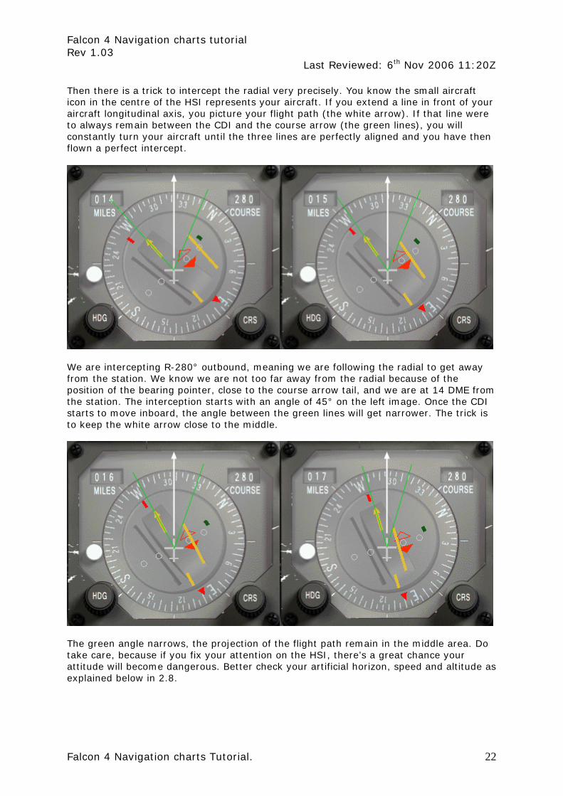
Then there is a trick to intercept the radial very precisely. You know the small aircraft icon in the centre of the HSI represents your aircraft. If you extend a line in front of your aircraft longitudinal axis, you picture your flight path (the white arrow). If that line were to always remain between the CDI and the course arrow (the green lines), you will constantly turn your aircraft until the three lines are perfectly aligned and you have then flown a perfect intercept.
We are intercepting R-280° outbound, meaning we are following the radial to get away from the station. We know we are not too far away from the radial because of the position of the bearing pointer, close to the course arrow tail, and we are at 14 DME from the station. The interception starts with an angle of 45° on the left image. Once the CDI starts to move inboard, the angle between the green lines will get narrower. The trick is to keep the white arrow close to the middle.
The green angle narrows, the projection of the flight path remain in the middle area. Do take care, because if you fix your attention on the HSI, there’s a great chance your attitude will become dangerous. Better check your artificial horizon, speed and altitude as explained below in 2.8.

Falcon 4 Navigation charts tutorial Rev 1.03
Last Reviewed: 6th Nov 2006 11:20Z
Falcon 4 Navigation charts Tutorial. 23
The green angle gets even narrower and on the right picture we are almost there. Since we are getting away from the station, the CDI will move slower at greater distance, so in this case, the interception is easy to perform because we have more time to make it nice.
Once established on the radial, all the reference lines are aligned. The CDI is centred on the course arrow, the 2 green lines are common and the white line is also aligned with the green one. As pictured on the left image, we made a textbook perfect intercept. Of course, in the cockpit, you don’t have the green lines or white arrow. Still there is the 12 o’clock mark on the HSI that could be used as the white arrow to help you, as pictured on the right image.
For the green lines, you will have to find your way, but it becomes second nature very quickly with a little experience.

Falcon 4 Navigation charts tutorial Rev 1.03
Last Reviewed: 6th Nov 2006 11:20Z
Falcon 4 Navigation charts Tutorial. 24
2.5. Tracking a radial once established Now that you know how to intercept a radial, let’s see if we can track it. Maintaining the aircraft on the selected radial is very easy in a no wind and no turbulence situation. And we all know we have a very stable platform with Falcon, so that makes things easy for you to learn basic radio-navigation. Still the HSI in the cockpit is small
and it’s very difficult to fly a heading to the degree. Add to that that the Course arrow only selects radials by 5° increment and you figure easily that ‘real’ precision flying is a view of the mind with our sim. Anyway, read on. Established on R-180° inbound the station, you need to fly a heading of 360°. Let’s say you concentrate on your mission and drift slowly to the 002° heading. It’s visible with your HUD heading tape, but you are head down in the cockpit checking the SMS system. (Next time turn the autopilot on, you rookie) Slowly, the CDI will start to drift to the left side of the course arrow. After a while, you notice the drifting of the CDI and decide to centre back on the selected radial. Now don’t go take a 45° interception angle to get back on course, there is a great chance that you will overshoot the line and zigzag around it. The best course of action here is to first fly a heading of 360° to stop the drifting from the radial then turn left 2 to 5 degrees (depending how far you have drifted) to gently intercept back the radial. Try to visualize the position in space by looking at the god’s eye view the HSI pictures for you. The yellow line is the set radial, you are in the small aircraft in the centre, and the CDI pictures the radial position. The intercept angle will become
obvious at a glance: place the longitudinal axis of the small plane always between the CDI and the course arrow. Turn your airplane accordingly and you will make a perfect interception. Once the CDI centres; turn right to fly a heading of 360° to remain on the radial. The closer you get to the station, the more precise the CDI will become, so it’s normal to have to adjust your course when you fly inbound an emitter. The contrary is true as well. The further you fly from a station, the least accurate the CDI becomes.

Falcon 4 Navigation charts tutorial Rev 1.03
Last Reviewed: 6th Nov 2006 11:20Z
Falcon 4 Navigation charts Tutorial. 25
2.6. What about the wind ? You know the wind will naturally push you on one side or the other of the radial, so depending on its force you will need to fly a wind corrected angle to remain perfectly aligned. Of course that means you need to be aware of the wind direction and speed – but that’s easy. Just dobber right on the DCS switch (SEQ position) while the DED in on the main page (STPT) and a new line will appear with wind settings. On the example on the right, wind is 340° at 9 Kts. With that information in mind, it’s easier to decide which wind correction angle to apply and especially on which side! Unfortunately, winds are not really a concern in Falcon and are usually very slow. So I just fly whatever heading necessary for the CDI to remain centred and I usually end up with a very small WCA – if not none at all.
2.7. Station passage. Imagine that you’re tracking R-130° inbound of a known tacan. Your flight plan will take you right over the emitter and then you will continue on your heading and fly on R-310° outbound the same tacan. You will overfly the station and your heading will remain unchanged on 130° (in a no wind situation). Nearing the station, the CDI which is centred will start to drift one side or the other. And the bearing pointer will make a 180°. Once the CDI starts to move (in F4, it usually starts at DME1) don’t try to follow it. You’re too close to the station and the instrument readings are inaccurate. Just fly along your heading until you are on the other side of the emitter where the CDI will centre again. It might not centre perfectly, and you may want to fly a new interception angle until it centres again. In real life, we talk about a cone of uncertainty (sp?) when we are that close to the station. It starts sooner the higher you fly. But in Falcon, it’s mostly happening very close to the station, whatever your altitude is.
Falcon 4 Navigation charts tutorial Rev 1.03
Last Reviewed: 6th Nov 2006 11:20Z
Falcon 4 Navigation charts Tutorial. 26
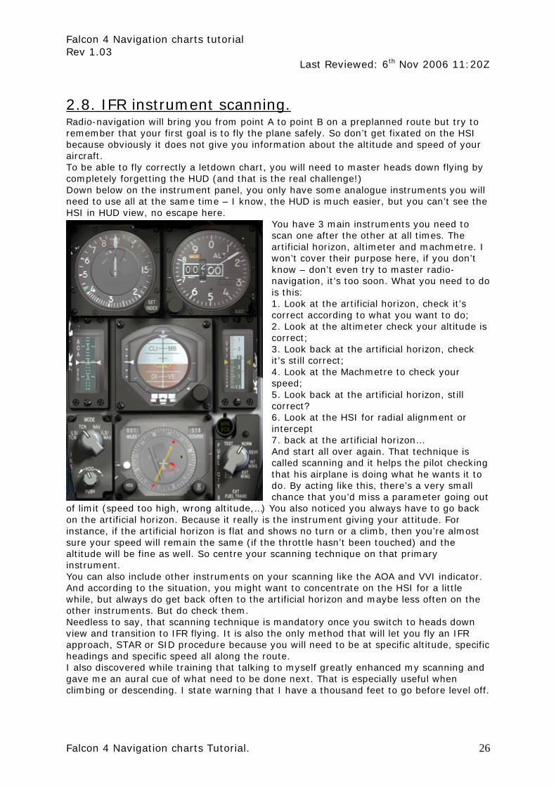
2.8. IFR instrument scanning. Radio-navigation will bring you from point A to point B on a preplanned route but try to remember that your first goal is to fly the plane safely. So don’t get fixated on the HSI because obviously it does not give you information about the altitude and speed of your aircraft. To be able to fly correctly a letdown chart, you will need to master heads down flying by completely forgetting the HUD (and that is the real challenge!) Down below on the instrument panel, you only have some analogue instruments you will need to use all at the same time – I know, the HUD is much easier, but you can’t see the HSI in HUD view, no escape here.
You have 3 main instruments you need to scan one after the other at all times. The artificial horizon, altimeter and machmetre. I won’t cover their purpose here, if you don’t know – don’t even try to master radio-navigation, it’s too soon. What you need to do is this: 1. Look at the artificial horizon, check it’s correct according to what you want to do; 2. Look at the altimeter check your altitude is correct; 3. Look back at the artificial horizon, check it’s still correct; 4. Look at the Machmetre to check your speed; 5. Look back at the artificial horizon, still correct? 6. Look at the HSI for radial alignment or intercept 7. back at the artificial horizon… And start all over again. That technique is called scanning and it helps the pilot checking that his airplane is doing what he wants it to do. By acting like this, there’s a very small chance that you’d miss a parameter going out
of limit (speed too high, wrong altitude,…) You also noticed you always have to go back on the artificial horizon. Because it really is the instrument giving your attitude. For instance, if the artificial horizon is flat and shows no turn or a climb, then you’re almost sure your speed will remain the same (if the throttle hasn’t been touched) and the altitude will be fine as well. So centre your scanning technique on that primary instrument. You can also include other instruments on your scanning like the AOA and VVI indicator. And according to the situation, you might want to concentrate on the HSI for a little while, but always do get back often to the artificial horizon and maybe less often on the other instruments. But do check them. Needless to say, that scanning technique is mandatory once you switch to heads down view and transition to IFR flying. It is also the only method that will let you fly an IFR approach, STAR or SID procedure because you will need to be at specific altitude, specific headings and specific speed all along the route. I also discovered while training that talking to myself greatly enhanced my scanning and gave me an aural cue of what need to be done next. That is especially useful when climbing or descending. I state warning that I have a thousand feet to go before level off.

Falcon 4 Navigation charts tutorial Rev 1.03
Last Reviewed: 6th Nov 2006 11:20Z
Falcon 4 Navigation charts Tutorial. 27
Or I always remind myself by speaking what would the next step to be completed. It’s really useful. Just be sure you are cold mike (teamspeak hotmike can spoil your reputation) My wife already has a good idea of my reputation, so I don’t care if she hears me ☺ !
2.9. Things to remember. Although what has been covered is only the very basic stuff, it’s enough for basic radio-navigation in Falcon. You should now stop reading and launch the sim to make some very basic exercises. Start by making sure you know how to fix your position with a tacan (by centring the CDI) and try some radial busting (90°) and finally some intercepts, both outbound and inbound. Experience will do the trick here – we aim for precision flight, so you will need to learn to intercept a radial with a nice curve and finish the turn perfectly aligned and directly correcting for wind drift. So get some practice, read back some pages from this document and/or call for help if anything is still unclear. Some points to remember:
• The interception angle will vary according to the distance of the emitter due to radial spead.
• The interception angle has to be determined accordingly to outbound or inbound intercepts.
• To intercept a radial by flying a nice curve, keep the longitudinal axis of the small HSI airplane between the CDI and the course arrow.
• Within 2 DME of a tacan, the reading of the HSI becomes erratic – just fly the constant heading
• Don’t forget to check the wind. • Reduce speed; it gives you more time to think things over. • When you’re heads down in the cockpit, SCAN the instruments or you’ll buy the
farm.

Falcon 4 Navigation charts tutorial Rev 1.03
Last Reviewed: 6th Nov 2006 11:20Z
Falcon 4 Navigation charts Tutorial. 28
3. Advanced Radio Navigation in Falcon.

Falcon 4 Navigation charts tutorial Rev 1.03
Last Reviewed: 6th Nov 2006 11:20Z
Falcon 4 Navigation charts Tutorial. 29
Before reading further, you should be able to intercept and track precisely any inbound or outbound radial while maintaining a set speed and set altitude. To follow the charts, you will need to understand the principles of some more advanced manoeuvres such as performing DME ARC, follow an ILS, study the different holding pattern entries and performing circle to land procedures. Offset tacan approaches will also be documented.
3.1 Following the ILS to the minima. The ILS works the same way as a fixed tacan radial along a runway centreline with some important differences though. It’s a double radio emitter. One emits in VHF for the localizer also referred as LOC, and is usually located at the end of the runway (opposed to the approach). The other emitter is paired to the localizer but emits in UHF for the glideslope, also called glide for short. It’s usually placed offset to the runway centreline at a distance from the approach end of the runway. The localizer provides guidance to the centreline of the runway and is pictured in the cockpit by the vertical line in the HSI and the ADI and the HUD. The width of the localizer emission cone varies between 3 and 6°. Such a small cone provides higher sensitivity of the CDI than when tracking a tacan radial. As a consequence, pilots tracking the ILS should make smaller corrections and should make them more promptly than tracking a simple radial. As mentioned above, the localizer emits only in the runway centreline direction. That’s why you don’t need to set the course for the HUD&ADI vertical bars to work as advertised. The HSI course arrow doesn’t really need to be set to the runway approach course, the reading of the CDI will remain correct to the ILS but it may lead to some confusion if the course arrow points backward. The deviation of the CDI will then be opposite to the side of the ILS. This is a normal behaviour when the course arrow points to a reciprocal heading of the approach runway heading. So to avoid any confusion, it’s better to set the HSI course arrow on the runway approach heading. That way the CDI deviation will point to the Localizer as it would to tracking a radial inbound. The glideslope provides the vertical guidance to the optimum descent profile which is usually 3°. In the cockpit, it is pictured by the horizontal needle in the HSI, ADI and HUD. Since the emitter is offset of the runway centreline, the glideslope can’t be followed until touchdown. Usually, pilots needs to transition from an instrument approach to a visual approach at the minima. There are visual aids helping the pilot’s transition at this critical point, we will cover these later on. ILS procedures also use two (or more) beacons along the approach track: the outer marker and the inner marker. Markers are displayed in the cockpit both visually by flashing lights and aurally by different frequency Morse code. Unfortunately, those markers beacons are not implemented in all Falcon versions. Only OF features them. The F-16 cockpit does have the corresponding instrument though: A green lighted indicator labelled MRK BCN on the right of the HSI, above the FUEL QTY panel.

Falcon 4 Navigation charts tutorial Rev 1.03
Last Reviewed: 6th Nov 2006 11:20Z
Falcon 4 Navigation charts Tutorial. 30
The markers provide range information to the runway. The outer marker is usually placed between 4 and 7 Nm from the runway threshold and is actually the point where the glideslope is intercepted. Inner marker are placed closer to the runway, usually 3500 feet and should be heard and seen in the cockpit around 200ft above the ground, usually near the minima. If it were implemented in F4, both markers would light up the MRK BCN indicator making it flashes at different frequency: (low freq for OM and higher freq for MM). Although in general aviation, the colours for each marker are different, in the F-16 cockpit, the indicator is monochrome and remains green. Backing up the visual cues, a different Morse code would be played in the pilot headset according to which marker is overflown: Outer: dashes / Middle: dot dash / Inner: dots Finally visual aids are placed on the runway to help the pilot’s transition from IFR flight to visual short final approach. In Falcon, those aids are the runway approach lights– which are always the same, whatever the airport and they don’t blink as much as a real system would do. The second help you will get is the VASI: Visual Approach Slope Indicator. This
system consist of a double bar row each side of the runway. The system reflects coloured lights according to your position on the 3° glidepath. The pilot should attempt to fly the aircraft so the far bars are red and the near bars are white. When all bars are red, the aircraft is below the glidepath and when all bars are white, the aircraft is above glidepath. There is a mnemonic to remember easily the VASI lights: “Red over white is alright – Red is dead” These systems are extremely useful especially in low light conditions when the lack of contrast makes the descent angle difficult to gauge for the pilot. Intercepting the ILS is done in two steps. The first step is to intercept the localizer. This usually happens at the longest distance from the runway. With the F4 charts it’s usually done between 14 and 9 DME. At this point, you concentrate on getting the localizer centred while having stabilized the aircraft at a certain altitude with a certain speed. Between 9 and 7 DME, you usually should be at
2000ft with the loc centred and the glideslope above you and coming down to meet your

Falcon 4 Navigation charts tutorial Rev 1.03
Last Reviewed: 6th Nov 2006 11:20Z
Falcon 4 Navigation charts Tutorial. 31
flight path. At DME 6 or 7 according to the approach, you should meet the glideslope (and the outer marker when implemented). Pop the airbrakes if they are not out already and lower the landing gear. In Falcon, extending the gear also lower the flaps so your aircraft may pitch up for a moment but speed will greatly decrease because of the increased drag. Usually, the drag created by the gear is enough to create a pitch down motion so your aircraft starts descending along the glidepath. If not, pitch down a little and place the flight path marker on the minus three degrees on the HUD scale. Concentrate on the instruments; keeping the Loc and glide centred the on speed AOA (13° green doughnut) and you should make a perfect approach. The HUD is a real great help here because you can keep the ILS indicators, speed tape, altitude and heading tape as well as the AOA indicators all in view at the same time. And on top of that the runway will be seen as well helping greatly the transition to visual approach at the minima.
Quite often, in F4 and in real life, you may get a visual on the runway well before reaching the minima just to loose the visual a few moments later because a low cloud drifted in the way or because of low fog. So care should be taken to keep scanning the instruments as long as you are unsure that the approach can be finished visually. Since you committed the minimum decision height to memory, you wait for this moment at the final stage of the approach (see the chart section for a discussion about the decision height) If the inner marker were implemented, that’s where it would sound. Pilots should then announce runway in sight and finish the approach using the VASI lights and maintaining the green AOA doughnut lighted. Would the runway not be in sight, the pilot should initiate a missed approach and call it on the radio.

Falcon 4 Navigation charts tutorial Rev 1.03
Last Reviewed: 6th Nov 2006 11:20Z
Falcon 4 Navigation charts Tutorial. 32
3.2. DME ARC Many instrument approaches start with a DME ARC because they are an easy mean to transition from the enroute phase of the flight to the final approach course. It seems quite complicated but actually it is very simple to fly. A DME ARC is simply part of a circle around an emitting station (here a tacan) at a given distance. The arc is 1 Nm wide and the pilot tries to remain within that arc by constantly turning toward the station. The trick is to keep a constant mental image of your position throughout the ARC and to the tacan. Larger arcs are easier to maintain than smaller ones. The speed at which you fly the arc will also define its difficulty level. Obviously higher speeds make it more difficult. And if you try to fly a small arc at high speed, you are in for a lot of fun! Flying a DME ARC is done in three steps: Intercepting the ARC, flying the ARC and intercepting the final approach course. The first and last parts are usually the most difficult ones because they usually induce a 90° turn which takes time to perform – luckily, our F-16 turn fast, even at 300 kts, much faster than a standard rate of turn of 3° per second. With such a rate of turn, a 90° turn takes about 30 seconds, which at 300 kts makes a 2.5 Nm long turn… If you fly 300kts and turn at a rate of 10° per second you will need 9 seconds to make the 90° turn. That makes a 0.75 Nm long turn at 300 kts. So you know you need to lead your turn by less than 1 DME to be precisely on the ARC. The final approach turn might be some more complicated since you will be considerably slower but we will cover this turn in the chart section. Maintaining the arc is done by using once again the red station bearing pointer. Since you want to turn around the station, all you actually need to do is to maintain the bearing pointer on your wingtip and turn accordingly so it remains there for the duration of the arc. It is as simple as that! As you see on the image on the next page, once the DME ARC has been intercepted (by leading the initial 90° turn), the bearing pointer is on the nine o’clock position on the HSI (left wingtip). That’s position #2. The aircraft flies a heading of 90° or already a little less. In a no wind situation, it would be possible to make a constant turn toward the station to maintain the bearing pointer exactly on the nine o’clock position and the required DME distance. In real conditions, it’s best to let the bearing pointer drift some 5 to 10° past the wingtip and then turn to replace it some 5 to 10° forward of the wingtip. And start the process as often as necessary to maintain the ARC. At position #2, If the pilot were to continue on this heading, it would reach position #3 and the bearing pointer would start drifting aft of the left wingtip position. The pilot should then turn left some so the bearing pointer points ahead of the left wingtip position. Then he can fly in a straight line, letting the bearing pointer points to the nine o’clock position and slightly past it, where the process start all over again. At position #3, If the pilot over correct (by placing the bearing pointer too far forward of the left wingtip position), he would find itself in position #4 with the DME indicator reading 11Nm. On the other hand, if he corrected not enough (by placing the bearing pointer not forward enough of the nine o’clock position) he would find itself in position #5.

Falcon 4 Navigation charts tutorial Rev 1.03
Last Reviewed: 6th Nov 2006 11:20Z
Falcon 4 Navigation charts Tutorial. 33
Falcon 4 Navigation charts tutorial Rev 1.03
Last Reviewed: 6th Nov 2006 11:20Z
Falcon 4 Navigation charts Tutorial. 34
Its simpler to fly the DME ARC on the inside of the curve, letting the ARC comes to you and then turning a little to replace the bearing pointer forward of the wingtip. To come back on track when inside the curve – like at position #4, a 10° turn (for each half mile deviation) outside the ARC is enough. If the pilot is outside the arc at position #5, a 20° turn (for each half mile deviation) inside the arc will be required to get back on the required DME ARC. That is of course when the bearing pointer is correctly placed on the wingtip position. AC #6 is spot on the DME ARC, flying a heading of 360° and having completed a 90° of the turn. AC #7 is also perfectly on the DME ARC and the pilot gets ready to intercept the final approach course as pictured by AC #8. A lead turn will be required to intercept correctly the radial – notice the 200° radial has been set on the Course arrow to give the reference point of the lead turn. Bear in mind that you might also want to intercept an ILS instead of a tacan radial. Refer to the approach chart section for an explanation of the final turn. Correcting for the wind may seem complicated since your heading is not constant and the wind correction angle will constantly change. If the wind is pushing you away from the station, place the bearing pointer ahead of the wingtip position and use this as the new reference for your turns. If the wind is pushing you towards the station, use a new reference point past the wingtip position. The wind correction angle is then easily viewed: it’s the angle between the wingtip position and the new reference point on the HSI. Beside speed, keeping the altitude at the correct level is critical. Quite often you are flying below the MSA (Minimum Safe Altitude) and there are mountains around you. So scan your instruments properly to not only remain on the DME ARC but also to keep the correct speed (300- 250 kts) and the correct altitude mentioned on the charts. Usually you start the DME ARC at a relatively high altitude and higher speed (350-300kts) and you want to leave the DME ARC at a lower altitude and with a lower speed near the gear down speed. As a consequence flying the DME ARC, you will need to change your speed and altitude according to the charts and that will certainly spoil your trim settings ☺ Did you know you can trim the F-16? Pretty handy flying an IFR procedure.
3.3. Tacan approach Following a tacan radial to the minima is the same kind of approach as the ILS, but with less guidance. You don’t have glideslope information while shooting a TACAN approach so the altitudes are given in levels to be at a certain distance from the runway threshold in the side view of the tacan approach chart (refer to the approach chart overview). Once again, pilots don’t need to fly in level. As long as they can reach a specific DME at the required altitude, they can fly a gentle descend to the minima. The other aspect specific to Falcon is that since all tacan stations are placed alongside the runway, most of the tacan approaches are offset from the runway axis. The reason is simple, by angling the final approach course from the runway centreline; it’s often possible to intersect the runway threshold at the minima. Then only a gentle visual turn is required to align the craft on the centreline. If the chosen tacan radial for the approach was the same as the runway axis (Radial 230° for a 23 runway for instance) the pilot would find himself parallel but aside the runway when looking out of his instrument at the minima. A visual S would then be needed to get on the runway centreline. This double turn is more difficult to fly than the angled approach. In the charts I created, both type of tacan approach are available… I found the angled radial trick a while after doing the first tacan approaches.

Falcon 4 Navigation charts tutorial Rev 1.03
Last Reviewed: 6th Nov 2006 11:20Z
Falcon 4 Navigation charts Tutorial. 35
In real life, we can find both approaches as well – but quite often, the emitter is placed somewhere on the runway centreline axis to allow easy alignment on a fixed radial. It’s not necessarily a Tacan; it can be a VORDME, a VORTAC or even a NDB. Since a final turn is almost always necessary for the pilot to align his aircraft visually with the runway, the minima for tacan approaches are always higher than an ILS approach. They are around 500 - 700 feet above ground level. That will leave plenty of time for the final line up.
Amendola runway 29 tacan approach is 20° offset and runs down the radial 130° on a 310° heading. As you can see DME 2 is perfectly aligned with the centreline and that’s where the minima is. So right there, a left line up turn is all it takes to get on the runway centreline.
Pusan RWY 14 tacan approach is not offset with the runway. As such the pilot will need to make an aligning S turn at DME3 to get on the centreline.
Falcon 4 Navigation charts tutorial Rev 1.03
Last Reviewed: 6th Nov 2006 11:20Z
Falcon 4 Navigation charts Tutorial. 36
3.4. Holding procedures Holding in Falcon is not something you will do often unless you are masochist ☺. Still performing a CAP is a kind of holding, albeit with longer legs. The charts have holding patterns published on most approach charts and even on some SID charts. So you need to know how to fly them and more difficult how to enter the holding area.
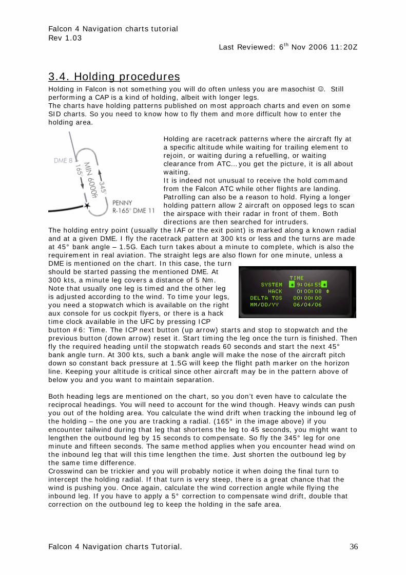
Holding are racetrack patterns where the aircraft fly at a specific altitude while waiting for trailing element to rejoin, or waiting during a refuelling, or waiting clearance from ATC… you get the picture, it is all about waiting. It is indeed not unusual to receive the hold command from the Falcon ATC while other flights are landing. Patrolling can also be a reason to hold. Flying a longer holding pattern allow 2 aircraft on opposed legs to scan the airspace with their radar in front of them. Both directions are then searched for intruders.
The holding entry point (usually the IAF or the exit point) is marked along a known radial and at a given DME. I fly the racetrack pattern at 300 kts or less and the turns are made at 45° bank angle – 1.5G. Each turn takes about a minute to complete, which is also the requirement in real aviation. The straight legs are also flown for one minute, unless a DME is mentioned on the chart. In this case, the turn should be started passing the mentioned DME. At 300 kts, a minute leg covers a distance of 5 Nm. Note that usually one leg is timed and the other leg is adjusted according to the wind. To time your legs, you need a stopwatch which is available on the right aux console for us cockpit flyers, or there is a hack time clock available in the UFC by pressing ICP button #6: Time. The ICP next button (up arrow) starts and stop to stopwatch and the previous button (down arrow) reset it. Start timing the leg once the turn is finished. Then fly the required heading until the stopwatch reads 60 seconds and start the next 45° bank angle turn. At 300 kts, such a bank angle will make the nose of the aircraft pitch down so constant back pressure at 1.5G will keep the flight path marker on the horizon line. Keeping your altitude is critical since other aircraft may be in the pattern above of below you and you want to maintain separation. Both heading legs are mentioned on the chart, so you don’t even have to calculate the reciprocal headings. You will need to account for the wind though. Heavy winds can push you out of the holding area. You calculate the wind drift when tracking the inbound leg of the holding – the one you are tracking a radial. (165° in the image above) if you encounter tailwind during that leg that shortens the leg to 45 seconds, you might want to lengthen the outbound leg by 15 seconds to compensate. So fly the 345° leg for one minute and fifteen seconds. The same method applies when you encounter head wind on the inbound leg that will this time lengthen the time. Just shorten the outbound leg by the same time difference. Crosswind can be trickier and you will probably notice it when doing the final turn to intercept the holding radial. If that turn is very steep, there is a great chance that the wind is pushing you. Once again, calculate the wind correction angle while flying the inbound leg. If you have to apply a 5° correction to compensate wind drift, double that correction on the outbound leg to keep the holding in the safe area.
Falcon 4 Navigation charts tutorial Rev 1.03
Last Reviewed: 6th Nov 2006 11:20Z
Falcon 4 Navigation charts Tutorial. 37
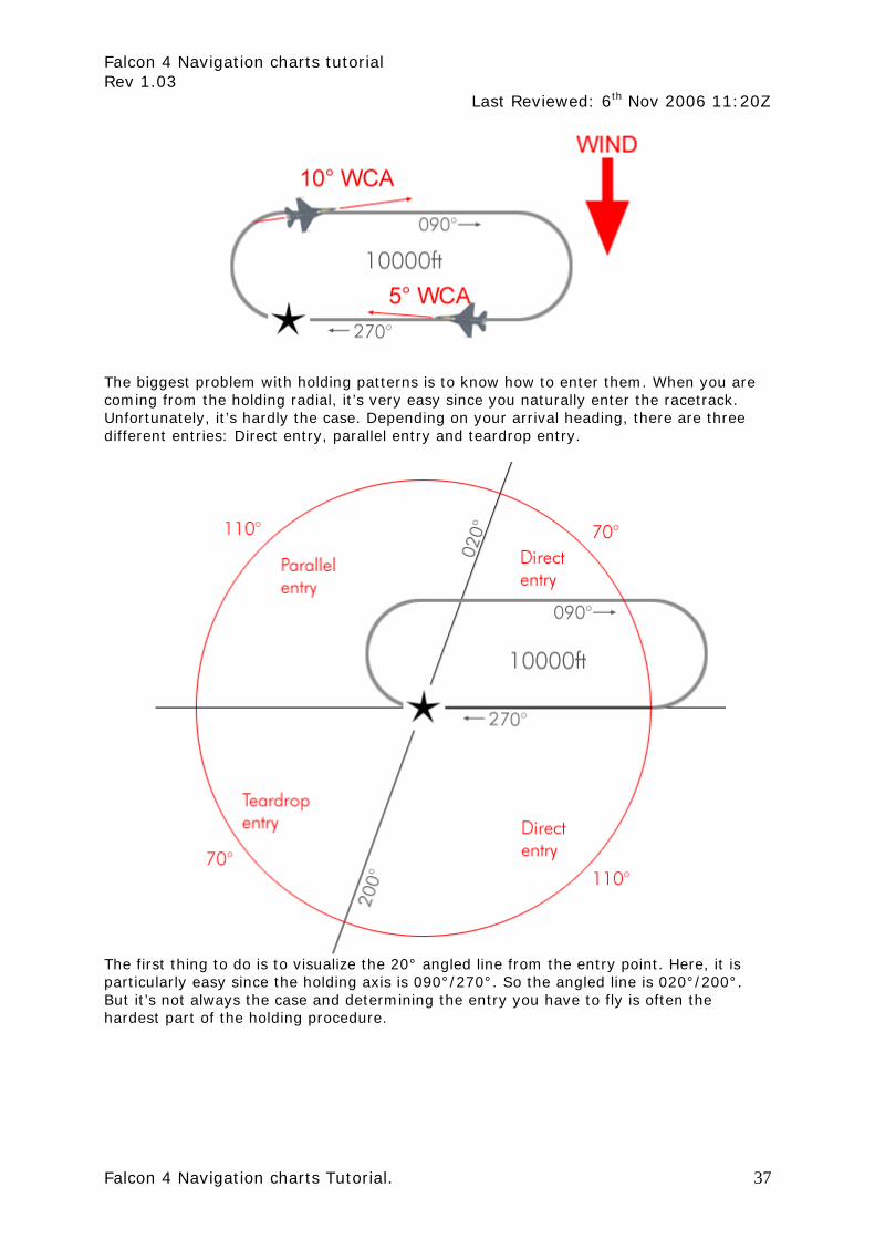
The biggest problem with holding patterns is to know how to enter them. When you are coming from the holding radial, it’s very easy since you naturally enter the racetrack. Unfortunately, it’s hardly the case. Depending on your arrival heading, there are three different entries: Direct entry, parallel entry and teardrop entry.
The first thing to do is to visualize the 20° angled line from the entry point. Here, it is particularly easy since the holding axis is 090°/270°. So the angled line is 020°/200°. But it’s not always the case and determining the entry you have to fly is often the hardest part of the holding procedure.

Falcon 4 Navigation charts tutorial Rev 1.03
Last Reviewed: 6th Nov 2006 11:20Z
Falcon 4 Navigation charts Tutorial. 38
3.4.1 Direct Entry The direct entry is the easiest one and luckily covers 180° of arrival route, so with a little planning, you can easily manage to always enter the racetrack with this procedure. Flying this entry, you just have to overfly the entry point, and then turn towards the outbound leg. It may take several turns for you to fly the correct racetrack but use the inbound leg to position your aircraft easily on the holding radial.
In the above example, the aircraft reach the holding area with a 315° heading which is within the direct entry quadrant. The pilot simply overflies the entry point, turn right to the outbound leg of 090° and start the clock when abeam the entry point. The racetrack should be easy to fly since the aircraft is almost directly established. If the aircraft was coming from the North East on a 220° arrival route, the pilot would do the same but since the initial turn will remain south of the holding area for a certain time, it might fly the outbound leg a little south of the published route. By intercepting the holding radial on the inbound leg, the pilot will be able to correct his racetrack.

Falcon 4 Navigation charts tutorial Rev 1.03
Last Reviewed: 6th Nov 2006 11:20Z
Falcon 4 Navigation charts Tutorial. 39
3.4.2 Teardrop Entry Obviously, turning directly as pictured would push you too far away from the racetrack. So when doing a teardrop entry, the pilot should aim his craft some 30° off the inbound track so he cuts the racetrack in two parts. Once established on this heading, time for a one minute leg and then start your right turn to intercept the holding radial.
Arriving from a 040° heading, the pilot overfly the entry point and then turn on a 060° heading which is 30° away from the holding radial. That will give him enough room to execute the intercept turn on the holding radial. He flies that teardrop leg for about 60 seconds before starting the turn.

Falcon 4 Navigation charts tutorial Rev 1.03
Last Reviewed: 6th Nov 2006 11:20Z
Falcon 4 Navigation charts Tutorial. 40
3.4.3 Parallel Entry As its name implies, the pilot will need to fly a parallel course outside the holding area before making a turn to intercept back the holding radial. After overflying the entry fix, the pilot will turn his craft to the reciprocal heading of the inbound leg while taking care to remain outside the holding area where other aircraft might fly the racetrack. That parallel course needs to be timed to one minute as well. Then turn left and cross the inbound holding radial and intercept it from the holding area. Once the radial is intercepted, proceed to the entry fix and fly the racetrack.
In real live, the holding patterns are rarely published on the charts and the ATC gives the hold instruction on the fly and it’s the responsibility of the pilot to visualize the racetrack mentally so he can decide which entry to use. In Falcon, since the ATC guys are kind of lazy, I decided to publish all the holding patterns, so you can have a quick reference and decide easily which entry to fly. The other aspect is that I didn’t use always standard holding pattern (with a right turn) but tried to ease up holding entries keeping in mind both the holding entry and the transition to the final approach. As a consequence, not all holding are standard. Just fly them the way they are pictured on the charts.
Falcon 4 Navigation charts tutorial Rev 1.03
Last Reviewed: 6th Nov 2006 11:20Z
Falcon 4 Navigation charts Tutorial. 41
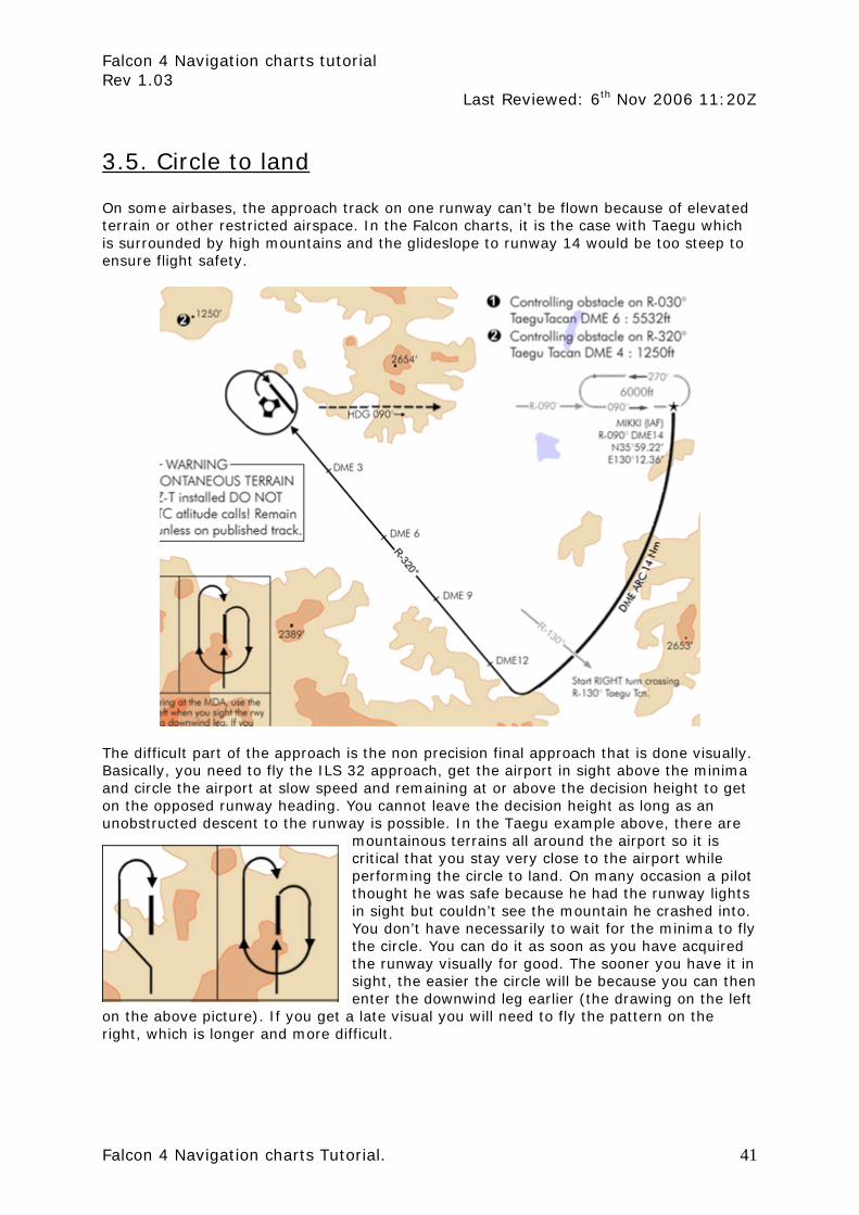
3.5. Circle to land On some airbases, the approach track on one runway can’t be flown because of elevated terrain or other restricted airspace. In the Falcon charts, it is the case with Taegu which is surrounded by high mountains and the glideslope to runway 14 would be too steep to ensure flight safety.
The difficult part of the approach is the non precision final approach that is done visually. Basically, you need to fly the ILS 32 approach, get the airport in sight above the minima and circle the airport at slow speed and remaining at or above the decision height to get on the opposed runway heading. You cannot leave the decision height as long as an unobstructed descent to the runway is possible. In the Taegu example above, there are
mountainous terrains all around the airport so it is critical that you stay very close to the airport while performing the circle to land. On many occasion a pilot thought he was safe because he had the runway lights in sight but couldn’t see the mountain he crashed into. You don’t have necessarily to wait for the minima to fly the circle. You can do it as soon as you have acquired the runway visually for good. The sooner you have it in sight, the easier the circle will be because you can then enter the downwind leg earlier (the drawing on the left
on the above picture). If you get a late visual you will need to fly the pattern on the right, which is longer and more difficult.

Falcon 4 Navigation charts tutorial Rev 1.03
Last Reviewed: 6th Nov 2006 11:20Z
Falcon 4 Navigation charts Tutorial. 42
It does look simple enough for most of you average Falcon flyer. However the circle to land is not an easy manoeuvre because you’re low and slow and need to fly precisely while keeping the runway in sight – which unless you have a Track IR will induces a new dimensions real pilots don’t have to cope with: the view panning. Beside when low and slow, your AOA will probably be close to 13° and forward visibility may be decreased. If at any time you loose sight of the runway, declare missed approach and climb as fast as you can on the missed approach track.