Embed Size (px)
Citation preview

MARINE SAFETY INVESTIGATION
REPORT 150
Independent investigation into the shift of cargo aboard the general cargo vessel
off the West Australian port of Bunbury
Sun Breeze
21 August 1999

Report No 150
Navigation (Marine Casualty) Regulations
investigation into the shift of cargo aboard
the general cargo vessel
Sun Breeze
off the West Australian port of Bunbury on 21 August 1999
Issued by the
Australian Transport Safety Bureau
June 2001

ISBN 0 642 20039 4
Investigations into marine casualties occurring within the Commonwealth's jurisdiction are conducted under the provisions of the Navigation (Marine Casualty) Regulations, made pursuant to subsections 425 (1) (ea) and 425 (1AAA) of the Navigation Act 1912. The Regulations provide discretionary powers to the Inspector to investigate incidents as defined by the Regulations. Where an investigation is undertaken, the Inspector must submit a report to the Executive Director of the Australian Transport Safety Bureau (ATSB).
It is ATSB policy to publish such reports in full as an educational tool to increase awareness of the causes of marine incidents so as to improve safety at sea and enhance the protection of the marine enviroment.
To increase the value of the safety material presented in this report, readers are encouraged to copy or reprint the material, in part or in whole, for further distribution, but should acknowledge the source. Additional copies of the report can be obtained from:
Inspector of Marine Accidents Australian Transport Safety Bureau PO Box 967 Civic Square 2608 ACT
Phone: 02 6274 6088 1800 621372
Fax: 02 6274 6699 Email: [email protected] Internet address: www.atsb.gov.au
ii

CONTENTS
Summary . . . . . . . . . . . . . . . . . . . . . . . . . . . . . . . . . . . . . . . . . . . . . . . . . . . . . . . . . . . . .1
Sources of information . . . . . . . . . . . . . . . . . . . . . . . . . . . . . . . . . . . . . . . . . . . . . . . . . .2
Narrative . . . . . . . . . . . . . . . . . . . . . . . . . . . . . . . . . . . . . . . . . . . . . . . . . . . . . . . . . . . . .5
Sun Breeze . . . . . . . . . . . . . . . . . . . . . . . . . . . . . . . . . . . . . . . . . . . . . . . . . . . . . . . . .5
The incident . . . . . . . . . . . . . . . . . . . . . . . . . . . . . . . . . . . . . . . . . . . . . . . . . . . . . . . .5
Loading at Bunbury . . . . . . . . . . . . . . . . . . . . . . . . . . . . . . . . . . . . . . . . . . . . . . . . . .6
Sailing from Bunbury, the list and subsequent events . . . . . . . . . . . . . . . . . . . . . . . . .9
Comment and analysis . . . . . . . . . . . . . . . . . . . . . . . . . . . . . . . . . . . . . . . . . . . . . . . . . .15
Evidence . . . . . . . . . . . . . . . . . . . . . . . . . . . . . . . . . . . . . . . . . . . . . . . . . . . . . . . . . .15
The charter party . . . . . . . . . . . . . . . . . . . . . . . . . . . . . . . . . . . . . . . . . . . . . . . . . . .15
Stability of the vessel . . . . . . . . . . . . . . . . . . . . . . . . . . . . . . . . . . . . . . . . . . . . . . . .15
Stability at first departure . . . . . . . . . . . . . . . . . . . . . . . . . . . . . . . . . . . . . . . . . . . . .16
Righting lever and heeling arm curves . . . . . . . . . . . . . . . . . . . . . . . . . . . . . . . . . . .17
Sun Breeze: Lightship KG . . . . . . . . . . . . . . . . . . . . . . . . . . . . . . . . . . . . . . . . . . . . .19
The Class Society . . . . . . . . . . . . . . . . . . . . . . . . . . . . . . . . . . . . . . . . . . . . . . . . . . .20
Cargo stowage . . . . . . . . . . . . . . . . . . . . . . . . . . . . . . . . . . . . . . . . . . . . . . . . . . . . .21
Notice of intention to load timber deck cargo . . . . . . . . . . . . . . . . . . . . . . . . . . . . . .22
Stowage factors, cargo weights and the master’s responsibility . . . . . . . . . . . . . . . . .23
Deck cargo lashings . . . . . . . . . . . . . . . . . . . . . . . . . . . . . . . . . . . . . . . . . . . . . . . . .23
Two scenarios for the incident . . . . . . . . . . . . . . . . . . . . . . . . . . . . . . . . . . . . . . . . . .25
Conclusions . . . . . . . . . . . . . . . . . . . . . . . . . . . . . . . . . . . . . . . . . . . . . . . . . . . . . . . . . .27
Submissions . . . . . . . . . . . . . . . . . . . . . . . . . . . . . . . . . . . . . . . . . . . . . . . . . . . . . . . . . .31
Details of Sun Breeze . . . . . . . . . . . . . . . . . . . . . . . . . . . . . . . . . . . . . . . . . . . . . . . . . . .33
Attachment 1 . . . . . . . . . . . . . . . . . . . . . . . . . . . . . . . . . . . . . . . . . . . . . . . . . . . . . . . . .31
Stability terminology and principles . . . . . . . . . . . . . . . . . . . . . . . . . . . . . . . . . . . . .35
Figures
1. Sun Breeze at Bunbury . . . . . . . . . . . . . . . . . . . . . . . . . . . . . . . . . . . . . . . . . . . . . . . .iv
2. General arrangement plan of Sun Breeze . . . . . . . . . . . . . . . . . . . . . . . . . . . . . . . . . . .4
3. Initial stow in lower hold showing broken stowage . . . . . . . . . . . . . . . . . . . . . . . . . . .7
4. Deck cargo shown after shifting . . . . . . . . . . . . . . . . . . . . . . . . . . . . . . . . . . . . . . . . .7
5. Lower hold cargo secured after incident . . . . . . . . . . . . . . . . . . . . . . . . . . . . . . . . . . .7
6. Chart showing positions of Sun Breeze after departing Bunbury . . . . . . . . . . . . . . . .11
7. Mate’s sketch of deck cargo lashings . . . . . . . . . . . . . . . . . . . . . . . . . . . . . . . . . . . . .24
8. Sun Breeze: Events and causal factors chart . . . . . . . . . . . . . . . . . . . . . . . . . . . . . . .28
iiiiii

Figu
re 1
:Su
n Br
eeze
at B
unbu
ry
iv

Summary The Panamanian flag general cargo vessel Sun Breeze berthed at the West Australian port of Bunbury on 16 August 1999 to load a cargo of sawn timber.
The vessel loaded packs of timber of various sizes, most of which had no weights marked on them. During loading, the master estimated weights of cargo loaded in each of the vessel’s two hatches by draught survey. When the hatches were full, the weight of cargo loaded on the hatch tops and deck was limited by the master’s requirement to maintain a minimum metacentric height (GM) of 50 cm.
After loading was completed on 21 August, the vessel's GM, after allowing for free surface effects in certain tanks, was calculated to be 47 cm.
After lashing of the deck cargo was completed, Sun Breeze sailed at 1800 the same day for China. The vessel was upright when the harbour master piloted it from the port. After the harbour master disembarked, the engine revolutions were increased to sea speed at 1830.
When the master left the bridge, the 3rd mate changed the steering from manual to
autopilot, at which time the ship started turning to starboard on its own accord. He changed back to manual steering, ordering helm to bring the vessel back on course. The vessel then seemed to him to list initially to port before listing to starboard.
The master returned to the bridge, by which time the list was about 15° or 20° to starboard. He stopped the engine and the list increased before settling at about 25°. The vessel lost some packs of timber from no. 1 hatch top over the side at this time. A distress message was sent out at about 1848 before the master anchored the vessel at 1900. The harbour master went out to the ship and non-essential crewmembers were disembarked by a tug.
The master corrected the list by ballasting side tanks. He advised the owner of the ship of the situation and obtained permission from the harbour master to re-enter the port after a surveyor had verified the vessel’s stability.
The vessel berthed at Bunbury once more at 1310 on the 22nd August. The cargo was restowed and secured and the amount of deck cargo was reduced, after which the vessel sailed for the discharge port in China, where it arrived safely on 10 September 1999.
1

2

Sources of information The master and crew of Sun Breeze
Australian Maritime Safety Authority
ClassNK, Survey Department
The harbour master, Port of Bunbury
C R Cox and Assoc. (Australia)
Adsteam Agency Pty Limited
ACRM, WA Inc
Stevedores, P&O Ports Limited
Ship Stability for Masters and Mates (Fourth Edition, Revised),D.R. Derrett
Acknowledgement Expert advice on stability was provided by:
R J Herd and Associates Pty Ltd
Dr Martin Renilson, Head of Naval Architecture and Ocean Engineering, Australian Maritime College
Mr Lindsay Emmett, Principal Marine Surveyor, Australian Maritime Safety Authority
3
Figu
re 2
:Ge
nera
l arr
ange
men
t pla
n of
Sun
Bre
eze
4

Narrative
Sun Breeeze The Panama flag Sun Breeze is a 11 478 tonne deadweight general cargo vessel, owned by N T Shipping S A. It was built in 1998 by Miura Shipbuilding Co Ltd of Japan and is classed with ClassNK (Nippon Kaiji Kyokai). The vessel was delivered to the owner on 9 February 1999, six months prior to the incident.
Sun Breeze is 109.30 m in length overall, has a beam of 19.8 m and a summer draught of 9.264 m. Propulsive power is delivered by a seven-cylinder Akasaka diesel engine developing 5,390 kW driving a single fixed-pitch propeller and providing a service speed of 13.5 knots. Electrical power is provided by 3 Daihatsu 6DL-20 generators each producing 480 kW.
The engine room and accommodation are at the after end (aft of frame 21). The vessel has two cargo holds, no. 1 about 36.2 m in length and no. 2 about 33.7 m in length. The total bale capacityI of the hatches was 14 811 m3. Each hatch is served by a 30 tonne derrick and there are two 30 tonne cranes between the hatches which can be ‘twinned’ for 60 tonne lifts.
The vessel has a capacity of 3 270 tonnes of water ballast in fore and after peak tanks, port and starboard deep tanks, nos 1 to 4 port and starboard double bottom tanks, no.2 centre double bottom tank and nos 1 to 4 port and starboard side water ballast tanks.
The master, who had been at sea for 34 years, had taken delivery of the vessel from the shipyard. He had sailed as mate for five
years on general cargo ships, log carriers and bulk carriers and had 22 years experience in command of various vessels, mainly bulk carriers. He had been master of wood chip carriers for 10 years and had been with his present company since he obtained a master’s certificate in 1977.
The mate had joined the vessel in Japan in July. He had been at sea for 26 years and held a master’s certificate since 1983. He had sailed as mate since 1981 on log carriers as well as bulk carriers and a wood chip carrier. This was the mate’s second contract with the owner of Sun Breeze.
The incident Previous voyages of Sun Breeze had been between Japan and Indonesia, Singapore, Malaysia and Thailand. Cargoes from Japan included steel coils, rolls and pipes. Cargoes from Asian ports included gypsum, plywood and tapioca flour. There had been no untoward incidents reported on these voyages.
On 2 August, the master received a fax from Ocean Rex Shipping Company Limited, Hong Kong, informing him that they were charterers for the next voyage. The vessel was to be delivered at Penang and redelivery would be at one safe port in North China or Japan at the charterer’s option.
The master’s voyage instructions were that the vessel was to load a minimum of 10 000 m3, up to the vessel’s full capacity, of jarrah and karri. He was advised that these were timber products to load at one safe berth at Bunbury, Australia for discharge at one safe berth at Jinzhou, China.
A description of the cargo included in the voyage instructions indicated that there were (approximately) 650 packs of 4.2 metre
I The capacity measured inside cargo battens, tank top or ceiling and the underside of underdeck beams, including spaces in the hatchways.
5

lengths of timber, 650 packs of 3 metre lengths, 20 packs of 4.5 metre lengths and 820 packs of 6 metre lengths. The master calculated that the space to load the total of (approximately) 2 140 packs amounted to 14 354 m3, without any allowance for broken stowageII.
The master was required to report the time of berthing as well as commencement of loading or discharging. The master was also to report daily, at 0800 local time, the quantity loaded or discharged during the previous 24 hours, stoppages incurred, balance to load or discharge, gangs working, weather conditions and estimated time of departure.
The master asked for the stowage factorIIIof the cargo and was advised that the stowage factor was 1.6. He was not sent a copy of the charter party. He was asked to try ‘his best’ to load all cargo under deck, but he was also advised that the charterers/shipper had the right to load cargo on deck and that he could ask the shipper for lashing materials for their account.
The master understood that the minimum cargo to load was 10 000 m3. He informed the charterers of the ship’s bale capacity and that the entire cargo would be loaded underdeck on the basis of the minimum figure of 10 000 m3. He asked the charterers to confirm whether this was correct, stating that he was confused. This was because the space required in the description of cargo was approximately 14 354 m3 and the shippers were said to have prepared about 15 000 m3. The latter figure was in excess of the vessel’s bale capacity.
The charterers replied by asking the master to note that the cargo had been fixed with them on the basis of lump sum freight and
that the vessel had been accepted. The shippers/charterers had the right to use all the vessel’s capacity including on-deck capacity. The master was advised that the ‘shippers/stevedore’ had made the stowage plan and thought that they could load all the cargo amounting to a total of 15 000 m3
including space required for broken stowage.
Loading at Bunbury Sun Breeze arrived at Bunbury at 2324 on 15 August 1999, anchoring off the port. The vessel berthed at 0655 on 16 August and loading of the cargo commenced at 0900 that day at both hatches.
The cargo comprised packs of four different dimensions. There were packs of 10.8 m3, 5.1 m3, 4.5 m3 and 3.2 m3, strapped with metal bands. The tiers of timber in packs of 10.8 m3 were separated by wooden slats. The other packs were strapped with no spaces between individual planks.
There was no stowage plan provided to the ship.
Forklift trucks were used to assist with the stowage in each hatch. Most of the packs of timber, of various sizes, had no weights stamped or otherwise marked on them. To calculate the weights of cargo in the various compartments and to arrive at the final cargo figures, the master carried out draught surveys.
While the lower holds were being loaded, the 3rd mate noticed that the stow was not tight. He informed the mate that there was broken stowage and the mate took up the matter with the stevedores. However, the cargo in the lower holds was not chocked or secured to prevent movement in a seaway.
II The space between individual packs and between packs and the ship's structure. III A figure which expresses the number of cubic metres which one tonne of cargo would occupy.
6
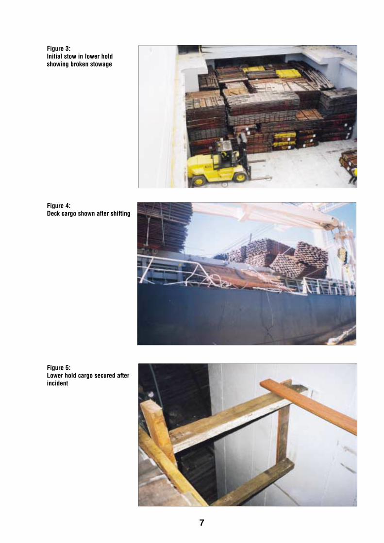
Figure 3: Initial stow in lower hold showing broken stowage
Figure 4: Deck cargo shown after shifting
Figure 5: Lower hold cargo secured after incident
7

While the tween decks were being loaded, the 3rd mate informed the mate that there were gaps in the cargo, even though forklift trucks were being used. He felt that, after he had mentioned this to the mate, there was an improvement in the cargo stowage. After completion of loading in the tween decks, the packs of timber were not secured even though the stow was not tight.
Prior to completion of loading, the master carried out a rolling test to determine the vessel’s stability. A crane was swung over the side to lift the last sling of cargo. The vessel’s moorings were slackened. The sling was hoisted and the hoisting wire was then slackened. The roll of the vessel was timed at 19-20 seconds and the master estimated, from tables in the stability data, that the metacentric height (GM) was about 50 cm.
Loading of two tiers of timber on the hatch tops was completed at 0415 on 21 August and lashing of the deck cargo commenced at 0500.
Between 0600 and 0900 that morning, after loading had been completed, the harbour master noted that the ship initially had a list to starboard of about 4°. It then had port list of about 4° before becoming upright. He became concerned about the vessel’s stability.
Sun Breeze was supposed to sail at 1200, but the agent changed the sailing to 1400, then to 1800. The harbour master told the agent that he was going to ask the master for the vessel’s stability calculation.
The harbour master went on board Sun Breeze at about 1500 to discuss the vessel’s stability with the master. The ship was upright then and the harbour master recalled the master saying that he was going to transfer fuel oil from high tanks to low tanks to provide additional stability. The master
gave the harbour master a copy of the stability calculation for the vessel’s departure condition, indicating that the GM, after correction for free surfaces effects in tanks, was 47 cm.
The harbour master asked the master how he knew what the weight of the cargo was and whether the packs of timber were marked with weights. The master said that the packs were not marked with weights and that he had estimated cargo weights by draught survey. The master’s reply gave the harbour master the impression that the master knew what he was doing.
The ship’s stowage plan and the mate’s stability calculation showed that the vessel had loaded 6 831 tonnes of timber and 2443 tonnes of fuel oil, diesel, fresh water and ballast on board.
Cargo distribution No. 1 Hatch No. 2 Hatch Total (tonnes) Lower hold 1842 1462 Tween deck 1278 1150 Coaming space 286 285 Hatch top 264 264 Total cargo 6831 Fuel oil (tonnes) No. 1 C FOT 0 No. 2 C FOT 80 No. 3 P&S FOTs 192 No. 4 P&S FOTs 281 Total fuel 553 Diesel oil (tonnes) No. 1 P&S DOT 72 No. 2 P&S DOT 55 Total diesel 127 Fresh water (tonnes) P&S FW tanks 119 Total fresh water 119 Ballast (tonnes) Deep tank (P) 170 Deep tank (S) 150 No. 1 P&S DBT 322 No. 2 P&S DBT 284 No. 2 C DBT 254 No. 3 P&S DBT 245 No. 4 P&S DBT 219 Total ballast 1644
Total dwt 9274
8

All fuel, diesel and fresh water tanks were slack and the mate’s stability calculation had taken account of free surface moments in those tanks. The ballast tanks were considered to be full and pressed up.
Neither the mate nor the master had plotted a curve of righting levers and had therefore not checked the areas under the curve against the International Maritime Organization (IMO) stability criteria. The vessel had no computer for calculating stability so the mate’s calculations of the GM were carried out manually.
Before the vessel sailed that evening, ballast in the deep tanks was adjusted to correct a list. The starboard deep tank was emptied and 61 tonnes were pumped out of the port deep tank. This would have reduced the GM by 5 cm.
Lashing of the deck cargo was completed at 1730 on 21 August and, after the master and mate had checked the lashings, the vessel sailed at 1800 with the harbour master conducting the pilotage. The draught was 8.09 metres forward, 8.31 metres aft and the freeboard was 5.63 metres. The master confirmed to the harbour master that he had carried out the transfer of fuel oil from high tanks to a low tank to increase the vessel’s stability.
Sailing from Bunbury, the list and subsequent events Sun Breeze was upright at sailing and when the vessel was assisted off the berth by a tug, the ship listed less than a degree. When the harbour master disembarked at 1815, he returned ashore and drove back to the wharf where Sun Breeze had been berthed, watching the ship. He had some lingering concerns about the vessel’s stability but, when there seemed to be no problems as the vessel proceeded outbound, he returned
home. By this time the sun had set and it was growing dark.
The ship’s initial course was 337° and the engine was at slow ahead. At 1830 the master put the engine to ‘full ahead sea speed’ for the passage. The vessel was being set to the east by the tide and he adjusted the course to 335°, using about 5 or 10° of port rudder to do so. He told the 3rd mate to maintain the course and to change to autopilot. The master then left the bridge and went to his cabin.
When the 3rd mate changed from manual steering to autopilot, the vessel started turning to starboard. The 3rd mate changed back to manual steering and ordered 10° of port helm to bring the vessel back on course.
At this time, the vessel started listing to port. The mate, who was on the bridge at the time, told the 3rd mate to telephone the master. The master’s phone was busy so the 2nd mate went below to call him.
When the mate was on his way to the bridge to take over the watch, he noticed that the vessel was taking a port list. He thought that the vessel might have taken a 15° list but, by the time he got to the bridge, the vessel was coming upright again. He telephoned the master asking him to come to the bridge, after which the vessel took a starboard list.
When the master returned to the bridge the list was about 15° or 20° to starboard. He stopped the engine. The rudder was amidships but the vessel was still turning to starboard. The list continued to increase as the vessel turned slowly. The ship attained a maximum list of about 30° to starboard before it reduced to about 25°. At about this time, lashings on the cargo on no. 1 hatch top released when securing clips opened and nine packs of timber were lost over the side.
9
Other packs on the same hatch shifted and came to rest on the starboard shipside rails.
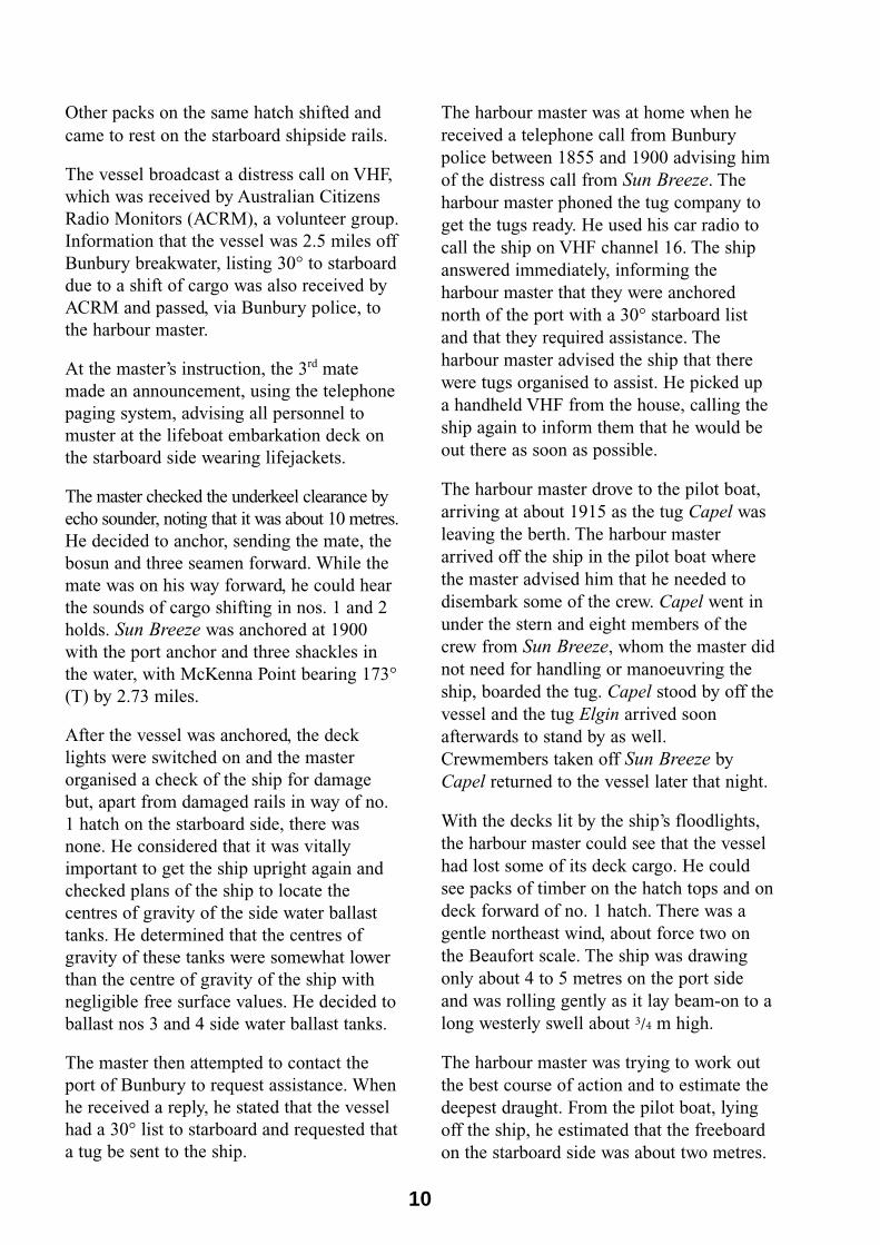
The vessel broadcast a distress call on VHF, which was received by Australian Citizens Radio Monitors (ACRM), a volunteer group. Information that the vessel was 2.5 miles off Bunbury breakwater, listing 30° to starboard due to a shift of cargo was also received by ACRM and passed, via Bunbury police, to the harbour master.
At the master’s instruction, the 3rd mate made an announcement, using the telephone paging system, advising all personnel to muster at the lifeboat embarkation deck on the starboard side wearing lifejackets.
The master checked the underkeel clearance by echo sounder, noting that it was about 10 metres. He decided to anchor, sending the mate, the bosun and three seamen forward. While the mate was on his way forward, he could hear the sounds of cargo shifting in nos. 1 and 2 holds. Sun Breeze was anchored at 1900 with the port anchor and three shackles in the water, with McKenna Point bearing 173° (T) by 2.73 miles.
After the vessel was anchored, the deck lights were switched on and the master organised a check of the ship for damage but, apart from damaged rails in way of no. 1 hatch on the starboard side, there was none. He considered that it was vitally important to get the ship upright again and checked plans of the ship to locate the centres of gravity of the side water ballast tanks. He determined that the centres of gravity of these tanks were somewhat lower than the centre of gravity of the ship with negligible free surface values. He decided to ballast nos 3 and 4 side water ballast tanks.
The master then attempted to contact the port of Bunbury to request assistance. When he received a reply, he stated that the vessel had a 30° list to starboard and requested that a tug be sent to the ship.
The harbour master was at home when he received a telephone call from Bunbury police between 1855 and 1900 advising him of the distress call from Sun Breeze. The harbour master phoned the tug company to get the tugs ready. He used his car radio to call the ship on VHF channel 16. The ship answered immediately, informing the harbour master that they were anchored north of the port with a 30° starboard list and that they required assistance. The harbour master advised the ship that there were tugs organised to assist. He picked up a handheld VHF from the house, calling the ship again to inform them that he would be out there as soon as possible.
The harbour master drove to the pilot boat, arriving at about 1915 as the tug Capel was leaving the berth. The harbour master arrived off the ship in the pilot boat where the master advised him that he needed to disembark some of the crew. Capel went in under the stern and eight members of the crew from Sun Breeze, whom the master did not need for handling or manoeuvring the ship, boarded the tug. Capel stood by off the vessel and the tug Elgin arrived soon afterwards to stand by as well. Crewmembers taken off Sun Breeze by Capel returned to the vessel later that night.
With the decks lit by the ship’s floodlights, the harbour master could see that the vessel had lost some of its deck cargo. He could see packs of timber on the hatch tops and on deck forward of no. 1 hatch. There was a gentle northeast wind, about force two on the Beaufort scale. The ship was drawing only about 4 to 5 metres on the port side and was rolling gently as it lay beam-on to a long westerly swell about 3/4 m high.
The harbour master was trying to work out the best course of action and to estimate the deepest draught. From the pilot boat, lying off the ship, he estimated that the freeboard on the starboard side was about two metres.
10
ACT
NSW
NT
1830
Qld
WA
SA
Vic
Tas
NT
NSW
ACT
Location of incident
1902 Sun Breeze anchor position
1835 approximate position at which cargo shifted
Figure 6: Chart showing positions of Sun Breeze after departing from Bunbury
11

The draught at that freeboard would have been about 11.75 metres.
The master contacted the owner of Sun Breeze and received advice to ballast the vessel. He instructed the engineers to go to the engine room to commence ballasting the side tanks. A log kept by the vessel shows that the list was progressively reduced to about 5° to starboard by ballasting the port side water ballast tanks, pressing up nos 3 and 4 tanks and partially filling no. 2 tank.
The mate calculated the vessel’s stability again with 140 tonnes of ballast in no. 2 port side ballast tank and 111 tonnes in no. 3 port side ballast tank. He reduced the deck cargo figure by 5 tonnes to account for timber lost overboard from no. 1 hatch top.
The mate’s calculation showed that the starboard deep ballast tank was empty and that the port deep ballast tank was partially full, with 135 tonnes of ballast remaining in it. No account was taken in his calculation of free surface moments in the port deep tank. Neither was any account taken of the transfer of fuel oil from high tanks to a low tank carried out prior to sailing.
This calculation, which was faxed to the harbour master, stated that the vessel now had a GM of 0.49 m, after allowing for free surface moments in tanks.
The master wanted to berth the vessel at Bunbury once more to check the stow, secure and re-lash the cargo, but the harbour master informed him that the vessel needed safety approval to enter the port.
The master contacted the owner of Sun Breeze advising him that the vessel was almost upright. The owner, in the meantime, had been in touch with the Protection and Indemnity (P & I) Club to arrange for a surveyor to board the vessel.
A surveyor appointed by the P & I Club boarded the vessel next morning, 22 August, to check the vessel’s stability. He sounded the tanks, recording different figures from those that had been faxed to the harbour master the previous night by the ship.
The surveyor’s figure for fuel oil tanks was 548 tonnes, distributed as follows;
Fuel Tanks Tonnes
No. 1 C 91
No. 2 C 85
No. 3 P&S 92
No. 4 P&S 280
The diesel oil tanks contained 124 tonnes and the fresh water tanks contained 120 tonnes. All fuel, diesel and fresh water tanks were slack.
The surveyor’s soundings for the ballast tanks revealed that no. 3 port double bottom tank (DBT) and no. 4 port and starboard DBT’s, that the mate had considered full, were slack. His soundings showed that the port deep tank was slack with 109 tonnes in it. His soundings also showed that there were 145 tonnes in no. 2 side ballast tank (P) and 80 tonnes in no. 3 side ballast tank (P).
The surveyor took account of the cargo that had been lost overboard, reducing the figure for the cargo that was originally loaded on top of no. 1 hatch by 44 tonnes.
The surveyor’s stability calculation determined that the GM, with nos. 2 and 3 side tanks ballasted, was 0.56 metres prior to correction for free surfaces in tanks and that it was 0.35 metres after correction for free surfaces. He informed the harbour master of the results of the calculation after which it was arranged that the vessel would enter the port once more.
12

The vessel berthed again at Bunbury, where it was found that the timber stacks in the lower holds and tween decks had leaned over to starboard, coming to rest against the ship’s side. The cargo on the hatch tops was discharged, after which the hatches were opened. Some packs of timber were opened and the contents stowed in the tween decks to fill existing gaps. The stow in the lower holds was chocked off. When the stow in the tween decks was secure, the hatches were
shut and only one tier of timber was loaded on the hatch tops on the advice of the classification society. After lashings were set up to secure cargo on the hatch tops in accordance with flag administration requirements, the vessel sailed at 2005 on 25 August for the discharge port in China, arriving there at 0600 on 10 September 1999 without further incident.
13

14

Comment and analysis
Evidence The Australian Transport Safety Bureau (ATSB) interviewed the master, the mate, 2nd and 3rd mates and the harbour master.
The following documents were obtained to assist with the investigation
• the vessel’s stability calculation at departure
• the stability calculation that was sent by fax to the harbour master at about 2200 after the vessel had listed and was anchored.
• the surveyor’s calculation of stability on the morning after the incident
• a copy of the vessel’s approved stability data
• copies of the vessel’s logbook and bell book
• a plan with quantities of cargo loaded in the hatches and on deck
• a copy of the relevant page from the sounding book
• the general arrangement and midship section plans.
Information was obtained from the classification society, ClassNK, by correspondence.
Advice was obtained from three professional naval architects relating to the vessel’s stability data and its stability.
The charter party The master was responsible for the safety of the ship, the personnel on board and the cargo. His responsibilities were complicated by the difficulty that he experienced with insufficient advice in respect of the cargo that was to be loaded at Bunbury.
The master had to deal with the charterer and the charterer’s agent and he should have been provided with a copy of the charter party.
He was confused by the instructions that he had received as he found them ambiguous. The instructions seemed to suggest that the cargo should be loaded underdeck, but the volume of cargo exceeded the vessel’s bale capacity. The charterers then advised him that they had the right to load on deck. He was also told that the shippers/ stevedore had made the stowage plan. In fact there was no such plan. The paucity of information available to him made it impossible for the master to prepare a pre-loading plan. In the event, the master developed his own plan progressively after each compartment was loaded.
The master was not provided with a copy of the charter party, neither was he provided with adequate information on the cargo.
Stability of the vessel The IMO Code of Safe Practice for Ships carrying Timber Deck Cargoes provides that the ship should be supplied with comprehensive stability information which takes into account timber deck cargo. This information should enable the master, rapidly and simply, to obtain accurate guidance as to the stability of the ship under varying conditions of service. The code states that the stability of the ship at all times should be positive and to a standard
15

acceptable to the flag state. The stability should allow for:
• the increased weight of timber deck cargo due to absorption of water
• ice accretion if applicable
• variations in consumables
• free surface effects of liquids in tanks, and
• the weight of water trapped in broken spaces within the timber deck cargo.
The master had neither a copy of this code of safe practice, nor was there stability information available to him that took into account carriage of timber deck cargo.
The master set his limiting stability criteria for Sun Breeze at a minimum GM of 50 cm. To maintain this GM, he should have calculated the stability for arrival at the discharge port, allowing for consumption of fuel, free surface effects of fuel and ballast, the increase in weight of timber on deck by water absorption as well as any transfer of weights within the ship that might have been planned to maintain stability.
The ship’s stability calculations made no allowance for the increased weight of timber deck cargo as a result of absorption of water. This increase in weight could be as much as 10%. There was no allowance made for consumption of fuel for the voyage to China, neither was there any allowance for the weight of water likely to be trapped in broken spaces within the timber deck cargo.
Had this calculation been carried out the master would have been alerted to the need to reduce the quantity of cargo on the hatch tops in order to maintain a minimum GM of 50 cm at all stages of the voyage including arrival at the discharge port.
Stability at first departure According to the daily soundings in the deck log, on 21 August, the day when the vessel sailed from Bunbury, the only ballast on board was in the deep tanks and nos 1, 2, 3 and 4 DBT’s. Prior to sailing on 21 August, the starboard deep tank was emptied and the port deep tank was partially deballasted, but according to the mate’s figures for his stability calculations, the double bottom tanks were full.
The deck log made no mention of the double bottom tanks being pressed up prior to departure, but an increase in the tank soundings recorded in the sounding book would suggest that the tanks were pressed up on 19 August.
When the P&I surveyor checked the tanks after the incident, he confirmed that the port deep tank had 109 tonnes of ballast in it and that the starboard deep tank was empty. His figures showed that nos 1 and 2 and no. 3 (S) DBT’s were full. However, he found that no. 3 (P) DBT and no. 4 (P & S) DBT’s were slack.
After the incident, the stability at the vessel’s first departure was assessed for a condition where the side water ballast tanks were empty and the P&I surveyor’s figures for fuel oil, diesel oil and fresh water were used. These figures, in terms of tank contents and free surface moments, were considered to be more accurate than those that the mate had used and the ATSB recalculated the vessel’s stability upon its first departure from Bunbury.
There were two figures in the stability booklet for free surface moments for no. 1 fuel oil tank. The tabulated maximum moment of inertia (I max) was 439.1 m4, but a worked stability example in the booklet illustrating the departure ballast condition used an I x SG figure for the free surface
16

moment of 1 288.39 tm. This suggested that the correct figure for the I max value should be around 1 356 m4. An inspection of the ship’s plan in the stability book confirmed that the moment of inertia for no. 1 fuel oil tank should be greater than that of no. 2 fuel tank because of its greater width. The tabulated value of I max for no. 2 fuel tank was 973 m4.
This matter was referred to the classification society for the vessel, Class NK. The society confirmed that the value for I max was erroneously indicated as 439.1 m4, stating that the correct value was 1 356.2 m4. The class society also stated that they had thoroughly checked the stability book and had amended the I max for no. 4 fuel oil tanks.
In transferring fuel oil from no. 3 tanks to no. 1 tank, the master thought, on the basis of the information in the stability data, that he was increasing the vessel’s stability before sailing. The effect, however, was to reduce the vessel’s stability by about 7 cm because of the large free surface effect of no. 1 tank.
Using the P&I surveyor’s figures, the displacement obtained at departure at 1800 on 21 August was 12 891 tonnes. The vertical position of the centre of gravity (KG) of the vessel, after allowing for free surface moments of tanks, was 8.04 metres and the vessel’s fluid GM was 0.21 metres. There was a difference in cargo distribution between the mate’s figures and those used by the ATSB. It had been determined that there was timber on both hatch tops and on the deck forward of no. 1 hatch. The amount on each hatch top was estimated to be 235 tonnes and that on deck was estimated to be 58 tonnes.
Righting lever (GZ) values were obtained for this condition and the curve of righting levers was sketched. GZ values at 5° and 12° of heel were only 0.02 m and 0.065 m. At 20°, 30° and 40° of heel the GZ values were 0.169, 0.447 and 0.755 m. The areas under the curve from 0° - 30°, 0° - 40° and between 30° and 40° exceeded IMO criteria and the angle of vanishing stability was about 75°.
Based on the information from the approved stability data, the vessel seemed to be tenderIV, but the figures gave no indication of negative stability to cause an angle of loll.
In any event, the stability appears to have been marginal. If at sailing, in addition to no. 3 (P) DBT and no. 4 (P&S) DBTs being slack, the ballast tanks nos. 1 (P&S) DBTs and no. 2 (C) DBT were also slack, the free surface effects of these tanks would have reduced the GM to zero. If, at sailing, all ballast tanks were slack, the vessel would have had a negative GM. The effects of all ballast tanks being slack would have been to reduce the GM to negative 5 cm. With this GM, the vessel would have developed an angle of loll of 8.95°.
The probable marginal nature of the stability is reinforced by an analysis of the righting lever and heeling arm curves based on the list experienced by Sun Breeze.
Righting lever and heeling arm curves After the incident, when the vessel returned to the berth at Bunbury, the cargo was found to have moved through a distance estimated to be about half a metre in the lower holds and about a quarter of a metre in the tween decks.
IV A ship with a comparatively small GM and righting levers, with a long, slow roll.
17

There was about 3 300 tonnes of timber in the lower holds and about 3000 tonnes in the tween decks. With a shift of 0.5 metres in the lower holds and 0.25 metres in the tween decks, the moments due to these shifts are;
3 300 x 0.5 tonne metres (t/m) or 1 650 tm in the lower holds and,
3 000 x 0.25 or 750 t/m in the tween decks.
The total moment, 2 400 t/m, would have resulted in a shift of the vessel’s centre of gravity of 0.1861 m (2 400/12 891, moment/displacement).
The heeling arm curve with appropriate values (0.1861 x cosine angle of heel) for this shift of cargo was superimposed on the GZ curve (see
GZ values (metres)
GZ values from Angle of GZ GZ cross curves heel (KG=8.04) (KG=8.15) (assumed KG 5.5m) (Degrees) (metres) (metres)
diagram below and heeling arm curve 1). The point of intersection of the two curves was at 20°, indicating that the vessel should have heeled to about 20°.
Although the evidence given by the ship’s crew suggested that the list may have been as much as 30°, the inclinometer on the bridge of the vessel was observed to indicate an angle on the starboard side of 26°. Such a list indicates that the shift of cargo might have been underestimated or that the GZ curve was incorrect or that both the shift of cargo and the GZ curve were incorrect.
The estimated shift of cargo was considered to be reasonably accurate and additional GZ curves were plotted for GM values of 10 cm, nil and –10 cm. The heeling arm curve was found to cut the latter at 25°.
GZ GZ Heeling arm Heeling arm (KG=8.25) (KG=8.35) curve 1 curve 2
(metres) (metres) (metres) (metres)
0 0 0.000 0.000 0.000 0.000 0.186 0.488 0.242 5 0.021 0.011 0.002 -0.006 0.185 0.486 0.594 12 0.066 0.043 0.022 0.001 0.182 0.478 1.038 20 0.169 0.132 0.097 0.063 0.174 0.459 1.717 30 0.447 0.392 0.342 0.292 0.161 0.423 2.388 40 0.755 0.685 0.620 0.556 0.142 0.374
GZ and heeling arm curves
0.8
0.7
0.6
Heeling arm curve 1 0.5 Heeling arm curve 2(see page 22)0.4 GZ (KG=8.04)
0.3 GZ (KG=8.15) GZ (KG=8.25)
0.2 GZ (KG=8.35)
0.1
0
GZ (M
etre
s)
0 5 10 15 20 25 30 35 40
Angle of heel (Degrees)
18

If the vessel had listed to a maximum of 26° as indicated by the inclinometer, the fact that the heeling arm curve cut the GZ curve drawn for a GM of –10 cm at 25°, could indicate that the vessel had negative GM at sailing.
Sun Breeze: Lightship KG Given that the approved stability data contained some inaccuracies, the information provided on the position of the centre of gravity in the lightship condition was checked. The vertical position of the centre of gravity of a ship is important from the point of view of initial stability and it is necessary to know this position with considerable accuracy. The position of the centre of gravity of the lightship must be determined by an inclining experiment and, at the same time, the lightship weight is determined.
The experiment consists of causing the ship to heel to a small angle to the vertical by moving known weights through known distances across the deck and noting the shift of pendulums of known length. The angle of inclination can be calculated from the deflection of the pendulums. Several shifts of weights are made to obtain a mean angle of inclination. Calculations are then carried out to determine the position of the centre of gravity of the ship. The draughts at which the ship is floating are observed and the lightweight of the ship is determined.
The accuracy of the GM depends on the magnitude of the weight shifted, the distance through which it moves, the length of the pendulum and its deflection.
The ideal situation during the inclining experiment would be for the ship to be undisturbed by outside forces. In practice, a ship without movement even in calm conditions is never achieved. Stray currents,
fitful breezes, steady winds, the influence of the catenary in mooring lines, slow movement of liquids in pockets in tanks, all contribute to pendulum movement. The observer at a pendulum must decide the mean position of a moving wire or cord and allow for the possibility of parallax error.
The International Maritime Organization (IMO) ‘Code on intact stability for all types of ships covered by IMO instruments’, resolution A. 749 (18), contains a chapter on determining lightship displacement and centres of gravity for all passenger ships and every cargo ship of 24 m and upwards. There is also an annex with detailed guidance on the conduct of an inclining test.
IMO recommends that the total weight used to incline a ship should preferably be sufficient to provide a minimum inclination of one degree and a maximum of four degrees of heel to each side, except for large ships where the angle of inclination should be a minimum of one degree to each side.
IMO also recommends that the pendulums should be long enough to give a measured deflection to each side of upright of at least 15 cm and that pendulum lengths of 4-6 m should be used. A pendulum shift of 150 mm or more is recommended since, if the pendulum does not settle and judgement has to be made as to the central position, the fluctuation is only a small percentage of the reading.
Section 7.3.2.5 of the Code on Intact Stability recommends that all tanks should be empty and clean or completely full and that the number of slack tanks be kept to an absolute minimum.
The report on the inclining experiment carried out on 21 January 1999 by the class society, ClassNK, on behalf of the Panama register shows that, when Sun Breeze was
19

inclined, the wind speed was 3 m/s and the sea was calm.
While being inclined, Sun Breeze had liquids in 26 tanks, 10 of which had free surfaces and the rest were regarded as being pressed up. The total mass of liquids was 1 927.45 tonnes or about 52.6 % of the lightship mass.
The mean angle of heel obtained from the shift of weights was only 0.36496° using a forward ‘plummet’ of 2.183 m and an after ‘plummet’ of 2.197 m. The mean deflection of the plummets measured aboard the vessel was only 14.11 mm for the fore plummet and 13.80 mm for the aft plummet. The deflection recommended by IMO is at least 150 mm, so the deflections measured aboard Sun Breeze were less than one tenth of the recommended deflection and the lengths of the plummets were about half the recommended length. Even though the deflections aboard the ship were measured in millimetres, the measurements of individual deflections were somehow made to an accuracy of one hundredth of a millimetre.
Since a ship, while being inclined is never absolutely still, the observer must judge the position of the pendulum. Under ideal conditions, a minimum movement of 1.5 mm would be expected, which, in the case of Sun Breeze, represents a variation of 10% of the average shift of the two plummets.
The standard test recommended by IMO for the inclining experiment employs eight distinct weight movements. In the case of Sun Breeze, only five weight movements were shown in the report of the inclining experiment and it was not possible to plot the diagrams illustrated in Annex 1 of the IMO Code of Intact Stability. The diagrams
assist with determining the influence of excessive free liquids or the effect of wind gusts as well as illustrating when a ship touched the bottom or was restrained by mooring lines.
Given that there were known inaccuracies in the ship’s approved stability book and that the ship’s light KG was not calculated in accordance with IMO criteria, the Inspector can not have confidence in the accuracy of the vessel’s stability calculations.
The Class Society When the ATSB raised these issues with ClassNK, the manager of the freeboard section stated that they had investigated inclining experiments carried out recently at Japanese shipyards. As a result of their investigations they found that the degree of measured heel angle was between 0.3° and 2° and that the mean deflection of the plummets was between 15 mm and 100 mm. They considered that, even though the heeling angle and deflections of the pendulums were close to the lower limits of Japanese shipyard practice, the centre of gravity of Sun Breeze was accurately obtained from the inclining experiment.
Despite the comments from ClassNK that the deflections of the pendulums on Sun Breeze were close to the lower limits of Japanese practice, the measured mean deflections of 14.11 mm and 13.80 mm were less than the lower limits of 15 mm. The ATSB brought this to the notice of the class society and also asked whether ClassNK observed standards other than those recommended by IMO Resolution A. 749(18).
ClassNK responded by stating that, with reference to standards for inclining experiments, they presently had only the
20

standard on the inclining test stipulated in the ‘Handbook for Ship’s Design’ edited by the Kansai Society of Naval Architects of Japan. A copy of the standard for the inclining test was attached, with brief instructions for the experiment contained in one section on the lower third of one page. By contrast, Chapter 7 of IMO Resolution A. 749(18) containing requirements such as preparation and procedures for inclining experiments, runs to more than seven pages and Annex 1 has sixteen pages of detailed guidance for the conduct of an inclining test.
IMO Resolution A. 749(18) invites Governments concerned to use the provisions of the Code as a basis for relevant safety standards, unless their national stability requirements provide at least an equivalent degree of safety. The Resolution also recommends that Governments concerned ensure that inclining tests are conducted in accordance with the guidelines specified in the Annex to the present resolution. However, the IMO standards are not mandatory.
ClassNK advised the ATSB that, henceforth, they would start investigating the necessity for preparation of detailed guidelines for inclining tests in accordance with IMO Resolution A. 749(18) and/or IACS Recommendation no. 31.
Cargo stowage Part 42 of the Australian Marine Orders – Cargo stowage and securing – for the purposes of section 191 of the Navigation Act, gives effect to Regulation 22 of Chapter V and Part A of Chapter VI of the SOLAS Convention, which came into force on 1 July 1996. Part 42, for the purposes of section 257 of the Navigation Act, generally makes provision for the stowing and securing of cargoes.
The Australian Marine Orders (Marine Orders) require, inter alia:
• before cargo is loaded at an Australian port, the shipper of the cargo must give the master appropriate information on the cargo in sufficient time to put into effect precautions necessary for proper stowage and safe carriage
• the cargo information is to include, among other requirements, a general description of the cargo, the gross mass of the cargo and any relevant special properties of the cargo
• a person must not load cargo onto a ship in any way other than in accordance with this Part
• cargoes must be loaded, stowed and secured to prevent as far as practicable, throughout the voyage, damage or hazard to the ship and persons on board and loss of cargo overboard.
The packs of timber offered for shipment aboard Sun Breeze were of various sizes. As a result, the timber stow in the lower holds and tween decks was unlikely to be tight enough to do away with the necessity to use chocking or shoring. The only advice that the master received on stowing or securing the cargo was a message from the charterers advising him that he could ask the shipper for lashing materials for deck cargo. However, the safe stowage and securing of cargo is good seamanship practice and was ultimately the master’s responsibility.
The stevedoring company was engaged to stow the cargo safely. They would have been aware of the requirements of the Marine Orders. Any discussions with the master and the mate on stowage and securing of the cargo should have included the necessity, because of the differences in pack sizes, to secure the packs of timber that were stowed underdeck. In any event, to ensure a safe voyage, the master should have insisted that the underdeck stow be secured.
21

The stevedores, in submission, stated in 42, nor was the cargo secured so as to part: prevent damage or hazard to the ship.
The general practice in the stevedoring industry is for the vessel to provide a loading plan prior to the commencement of loading. The vessel did not have the required information to establish a proper loading plan, but it was clear that all available spaces had to be filled.
All cargo was forklift stowed. Although the stow was tight, gaps could not be prevented, however the size of these gaps was minimal.
Lashing and securing of cargoes is the responsibility of the vessel. During loading there were no discussions regarding shoring and securing of the cargo.
As a point of observation made after inspecting the extent of shift of cargo, the cargo in general had moved less than one metre.
If, as the stevedores maintain, the stow was tight, the cargo underdeck should not have shifted.
The stevedore’s comment that the extent of the shift of cargo, in general, was less than a metre should be seen in its correct perspective. There were 6 303 tonnes of timber underdeck. Sun Breeze is a relatively small vessel and the quantity of cargo underdeck was almost half of the vessel’s displacement of 12 891 tonnes. Even a small shift of cargo could have a significant effect on the vessel’s stability and seaworthiness.
The effect of a shift of underdeck cargo through a distance of a metre would cause the ship’s centre of gravity to move through almost 0.5 metres (6300/12891). The list would have increased by about 9° (see intersection of GZ curves and heeling arm curve 2 on page 18) and the consequences for the vessel could have been far more serious.
The master was not provided with the information required by Marine Orders Part
Notice of intention to load timber deck cargo Provision 6 of Part 42 of the Australian Marine Orders requires that, at least 48 hours before commencing loading of a timber deck cargo at an Australian port, the owner, master or agent of the ship must furnish to the prescribed person for the port of loading a signed notice containing details of:
• the name and IMO number of the ship
• the port and berth of loading
• the identity or type, and approximate quantity of the cargo to be loaded, unless the prescribed person allows a shorter period of notice.
The prescribed person is defined as:
the surveyor in charge of marine surveys for the Australian Maritime Safety Authority (AMSA) in the State or Territory in which the port is situated, or the surveyor in charge of marine surveys for AMSA at the port of loading or, if there is none, at any convenient adjacent port.
Originally the master had thought that the cargo would be loaded underdeck, but it was soon obvious that a certain quantity of timber would have to be loaded on the hatchtops or the deck. Despite this, AMSA was not notified of the intention to load timber deck cargo aboard Sun Breeze.
Stowage factors, cargo weights and the master’s responsibility The bale capacity of Sun Breeze was 14 811 m3. For the investigation, the Inspector allowed 750 m3 for broken stowage, just over 5% of the bale capacity, the cargo spaces being box–shaped and fork lifts being used for the stow. The remaining space was 14 061 m3. If
22

the stowage factor was 1.6 as the master was advised, there was enough underdeck capacity for 8 788 tonnes (14 061 / 1.6) of timber.
In fact, only 6 303 tonnes of timber were stowed underdeck, which indicates either that the stowage factor was more likely to have been about 2.2 (14 061 / 6 303), or that the broken stowage was in excess of 30%.
According to provision 12 of Part 32 of the Marine Orders an article of cargo to be loaded on a ship at a port in Australia must be marked with its gross mass, in accordance with Appendix 19, by the shipper of the cargo. According to Appendix 19 (1) of the same Part, a package of gross mass of one tonne or more must not be loaded or unloaded unless it is marked with its gross mass. Few, if any, packs were so marked.
The stevedoring company should have been aware of the relevant legislation and the requirement for packages to be correctly marked should have been brought to the attention of the master.
In this case, the master had no way to tell the weight of individual packs or groups of packs. To comply with the charterer’s requirements and to calculate the vessel’s stability, he estimated weights in compartments and on deck by draught survey. There was no mention of securing arrangements for the packs of various sizes to be loaded underdeck. The master would have been justified in delaying loading of the cargo until he was satisfied that the ship could be loaded so as to ensure a safe voyage.
There are commercial pressures on masters to load cargoes and expedite voyages. There are reported examples of masters who have lost their employment for exercising their
professional judgement at the expense of commercial expediency. Shipowners, however, have an obligation to ensure that their ships are operated safely at all times. Under circumstances such as this, where safety might be compromised, the master should receive the support of an owner or manager.
The master did not have sufficient information to enable him to stow the cargo safely.
Deck cargo lashings Sun Breeze carried an approved Cargo Securing Manual but timber deck cargoes were not included in the manual. The mate’s sketch of lashings for the deck cargo for the vessel's first departure from Bunbury is shown below. The diagram shows lashings for two tiers of cargo on each hatch top.
Chapter 4 of the IMO Code of Safe Practice for Ships carrying Timber Deck Cargoes, on securing of cargoes, states that:
• every lashing should pass over the timber
deck cargo and be shackled to eyeplates
suitable and adequate for the intended
purpose and attached to the deck stringer
plate or other strengthened points
• lashings should be installed in such a
manner as to be, as far as practicable, in
contact with the timber deck cargo
throughout its full height.
On Sun Breeze the eyeplates were attached to the side of the track for the hatch cover rollers. The class society’s office in Sydney was advised after the incident by ClassNK in Japan that ‘the strength of securing for proposed lashing plan is calculated according to Annex 13-7 of cargo securing manual and within allowable strength when lashing points would be 29 points and above for each side’.
23

Side view
Plan view
Photographs taken after the incident show that, with the stow two tiers high not extending to the edges of the hatch covers, some lashings may not have been in contact with the deck cargo throughout its full height.
Chapter 4 also contains details of the breaking strengths of lashings and components as well as details of tightening devices used in conjunction with the lashings.
When the vessel lost nine bundles of timber over the side from no. 1 hatch top as the list to starboard developed, the wire lashings on
Figure 7: Mate’s sketch of deck cargo lashings
the timber cargo on hatch no. 1 had not parted. The lashings had opened, permitting the bundles of timber to be released overboard after the vessel listed. Other bundles on the hatch top moved to starboard and, restrained by the remaining lashings, came to rest on the starboard shipside rails.
The Code of Safe Practice for Ships carrying Timber Deck Cargoes recommends that where wire rope clips are used to join wire ropes,
• the number and size of clips should be in proportion to the diameter of the wire rope and should not be less than four at 15 cm intervals
24

• the saddle portion of the clip should be applied to the live load segment and the U- bolt to the dead or shortened end segment
• rope clips should be tightened so they visibly penetrate into the wire and be retightened after the lashing has been stressed.
An AMSA surveyor attended the vessel immediately after the incident and noted that some lashings had insufficient clips on them, also that a number of wire clips had U-bolts fitted to the live load segment. He noted, too, that a number of nuts that should have been used to tighten the bolts appeared to have been left slack, resulting in the lashings opening and releasing cargo overboard.
When the vessel sailed from Bunbury for the second time, there was one tier of timber on each hatch top, stowed and lashed in accordance with flag administration requirements.
Two scenarios for the incident Two possible scenarios would explain the shift of cargo on board Sun Breeze on 21 August 1999.
1. The vessel sailed with negative GM, resulting in an angle of lollV which caused the shift of cargo.
2. The vessel was tender at sailing and rolled under the influence of the swell, possibly also heeling under the influence of the rudder. The unsecured cargo in the
tween decks and lower holds shifted. The vessel listed, causing the deck cargo to shift. Lashings on the deck cargo opened, resulting in the loss of nine packages of timber over the side.
At best the vessel’s stability at sailing was marginal and substantially less than the master calculated. This was due in part to insufficient allowance for free surface effects in those ballast and fuel tanks that were not pressed up and erroneous data in the ship’s approved stability book.
The cargo in the holds was not secured. There is no dispute about this. There was a level of broken stowage underdeck, but the degree of broken stowage cannot be determined. The shift of cargo of 0.5 m in the lower holds and 0.25 m in the tween decks would account for a list in excess of 15°. The shift of deck cargo would also have contributed to the list.
It would seem that marginal or negative stability and the unsecured cargo combined to bring about the shift of the cargo.
The safety of the ship and its crew were compromised:
• through lack of information on the nature and weight of the cargo, and the disregard of loading requirements as detailed in Marine Orders Part 42
• by the unreliable nature of the approved stability data.
The angle, to port or starboard, to which an unstable ship inclines, floating in such a position that the centre of buoyancy is vertically below the centre of gravity. At the angle of loll, the GZ is zero.
25
v

26

Conclusions These conclusions identify the different factors contributing to the incident and should not be read as apportioning blame or liability to any particular organisation or individual.
Based on all the evidence available, the following factors are considered to have contributed to the incident:
1. All fuel, diesel, fresh water and some ballast tanks were slack, reducing the vessel’s stability.
2. The cargo in the holds and tween decks was not secured to prevent movement in a seaway in accordance with the approved cargo securing manual.
3. The ship’s stability was based on an inclining experiment that did not meet IMO approved standards. As a result, the position of the lightship centre of gravity is in question.
4. The stability information supplied to the ship contained incorrect data on free surface moments.
5. Packages of timber were not marked with their weights and the master had to estimate weights in each compartment by draught survey.
6. The lashings at hatch no. 1 were incorrectly set up, opening to permit the
cargo to be lost overboard after the vessel listed.
7. The voyage instructions mentioned lashings for the deck cargo. It made no mention of securing arrangements for cargo in the hatches.
8. The master did not have a copy of the charter party, neither was he informed of correct stowage factors or weights of the type of cargo to load. He did not have sufficient information with which to prepare a proper loading plan and exercise proper oversight of loading.
9. The owner, master and the vessel’s agent did not inform the Australian Maritime Safety Authority that the vessel would be loading timber deck cargo.
10.The master did not have a copy of the code of safe practice for the carriage of timber deck cargoes, neither did the ship’s approved cargo securing manual include timber deck cargoes.
11.The stability calculations did not allow for absorption of water by the deck cargo or for consumption of fuel from low tanks once the vessel was at sea.
In addition, the Inspector considers that the master would have been justified in delaying loading of the cargo until he was given all information necessary to ensure the ship's safety.
27

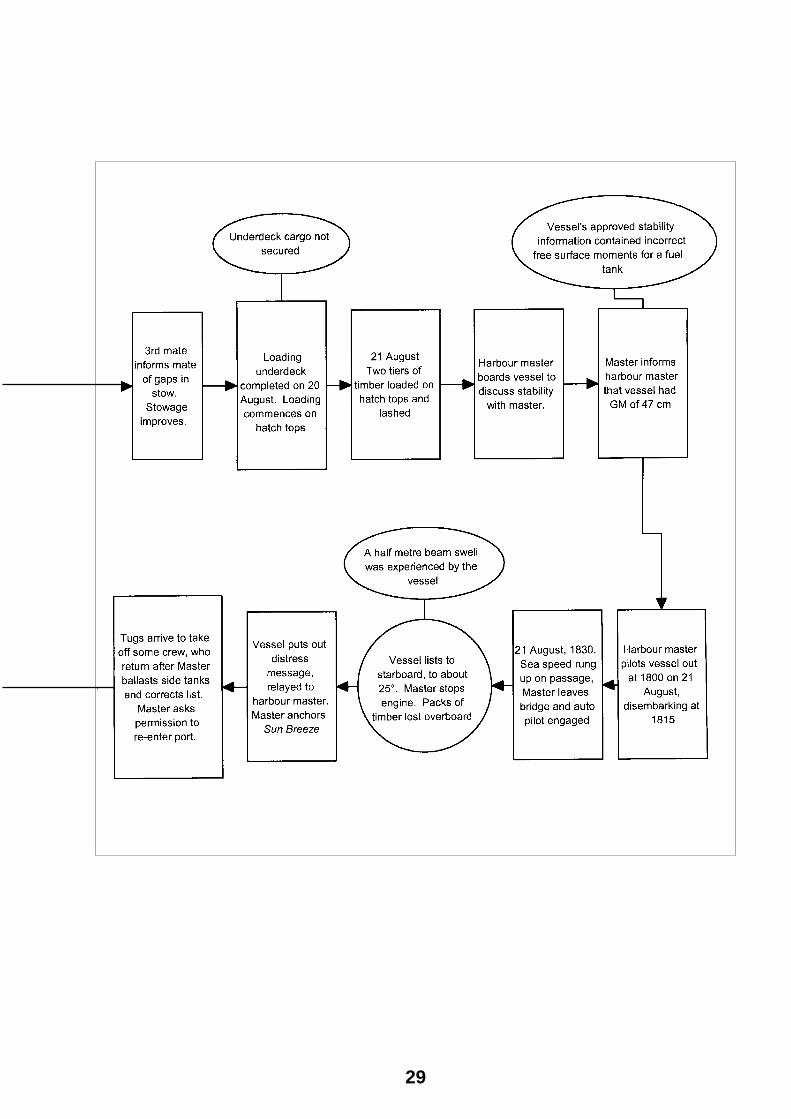
Figure 8: Sun Breeze: Events and causal factors chart
28
29

30

Submissions Under sub-regulation 16(3) of the Navigation (Marine Casualty) Regulations, if a report, or part of a report, relates to a person’s affairs to a material extent, the Inspector must, if it is reasonable to do so, give that person a copy of the report or the relevant part of the report. Sub-regulation 16(4) provides that such a person may provide written comments or information relating to the report.
The final draft of the report was sent to the following:
The master, mate, 2nd and 3rd mates of Sun Breeze
The owner of Sun Breeze
The harbour master, Bunbury Port Authority
Class NK
AMSA Fremantle
Director, Department of Marine Safety, Panama
The stevedores, P&O Ports
CR Cox and Associates (Australia)
Submissions were received from the master and owner of the vessel, the harbour master of Bunbury Port Authority, Class NK, AMSA Fremantle and the stevedores. The report was amended where necessary.
31

32

Details of Sun Breeze IMO No. 9197179
Flag Panama
Classification Society ClassNK, Nippon Kaiji Kyokai
Vessel type General cargo
Owner N.T. Shipping S. A.
Year of build 1998
Builder Miura Shipbuilding Co., Ltd, Japan
Gross tonnage 7 816
Summer deadweight 11 478 .26 tonnes
Length overall 109.30 m
Breadth, moulded 19.8 m
Draught (summer) 9.264 m
Engine Akasaka Diesel, type 7UEC33LS
Engine power 3 964 kW
Service speed 13.5 knots
Crew 20 (18 Filipino, one Japanese, one Korean)
33

34

Stability terminology and principles The centre of gravity of a body, or vessel, is the point through which the force of gravity is considered to act vertically downwards with a force equal to the weight of the vessel.
The centre of buoyancy is the point through which the force of buoyancy is considered to act vertically upwards with a force equal to the weight of the water that the vessel displaces. It is the centre of gravity of the underwater volume of the body.
To float at rest in still water, a vessel must displace its own weight of water, and the centre of gravity must be in the same vertical line as the centre of buoyancy.
Figure a
w
W L
w
K
M
B
G
Figure (a) represents a vessel floating upright in still water. The centre of gravity is shown as point ‘G’ and the centre of buoyancy is at point ‘B’. The letter ‘K’ denotes the keel.
Attachment A Figure b
w
W
L
w
K
W1 L1
M ø
B B1
G Z
If the vessel is inclined by an external force to a small angle as shown in Figure (b) the centre of gravity will remain at G and the weight of the vessel ‘w’ is considered to act vertically through this point. The centre of buoyancy, being the centre of gravity of the underwater volume, will move from B to B1.
For angles of heel up to about 15º, the vertical through the centre of buoyancy may be considered to cut the centre line at a fixed point. This point is known as the initial metacentre ‘M’.
The height of the initial metacentre above the keel depends on the vessel’s underwater form.
The vertical distance between G and M is referred to as the metacentric height. As long as G remains below M the vessel has a positive metacentric height.
A ship is in stable equilibrium if, when inclined, it tends to return to the initial position. For this to occur G must remain below M.
35

Figure (b) shows the vessel inclined at a small angle. The centre of buoyancy moves from B to B1 and the force of buoyancy is considered to act vertically upwards though B1 and the metacentre M. If moments are taken about G, there is a moment to return the ship to the upright position. This moment is referred to as the ‘moment of statical stability’ and is equal to the product of the force ‘w’ and the length of the lever GZ.
When a ship, which is inclined to a small angle of heel tends to heel still further, it is in unstable equilibrium. The centre of gravity is above the metacentre and the ship has a negative ‘GM’.
Figure (c) shows a vessel in unstable equilibrium. While G stays above M the lever GZ forms a capsizing lever.
Figure c
w
W
Lw
K
W1 L1 M
B B1
GZ
The distance GM or metacentric height is sometimes referred to as a measure of a vessel’s stability but this will only apply to small angles of heel when GM can be considered constant. A better measure of stability is the GZ lever.
This measure of a vessel’s stability can be represented by plotting a graph of the values of GZ, the righting lever, against various angles of heel. This plot is known as the GZ curve and the area under the curve, is
used in various regulations as a parameter by which to specify requirements for a vessel’s stability.
From the GZ curve can be determined:
• The range of stability
• The angle of vanishing stability
• The maximum value of GZ and the angle of heel at which it occurs
• The initial value of GM.
The range of stability is the range over which the ship has positive righting levers. The angle of vanishing stability is the angle of heel at which the sign of the righting lever changes from positive to negative.
36

![ダイハツ工業株式会社 総合トップページ...I ,320 200 (2ü) ¥9, 1 DAIHATSU] (2ü) ¥7 ,832 20 04 DAIHATSU DAIHATSU DAIHATSU DAIHATSU DAIHATSU DAIHATSU Exterior 05 McGað@](https://img.pdfslide.net/doc/110x75/60ca5a0dd8b5b85148317d81/fffc-cffffff-i-320-200-2-9.jpg)