Embed Size (px)
Citation preview

ARMY TM 11-5895-1220-12NAVY EE160-RG-OMI-010/W110-GRC215
AIR FORCE TO 31R2-2GRC215-1
OPERATOR’S AND UNITMAINTENANCE MANUAL
RADIO SETAN/GRC-21 5
(NSN 5895-01-156-0456)
DEPARTMENTS OF THE ARMY, THE NAVY, AND THE AIR FORCE1 JULY 1990
HOW TO USETHIS MANUAL III
EQUIPMENTDESCRIPTIONAND DATA 1-5
PRINCIPLESOF OPERATION 1-29
OPERATING -INSTRUCTIONS 2-1
OPERATORMAINTENANCE 3-1
UNITMAINTENANCE 4-1
SUBJECTINDEX I-1

This publication is required for official use or foradministrative or operational purposes only. Distributionis limited to US Government Agencies. Other requestsfor this document must be referred to Commander, USArmy Communications-Electronics Command and FortMonmouth ATTN: AMSEL-LC-ME-P, Fort Monmouth, NJ07703-5000.
DESTUCTION NOTICE-Destroy by any method that willprevent disclosure of contents or reconstruction of thedocument.

ARMY TM 11-5895-1220-12NAVY EE160-RG-OMI-010/W110-GRC215
AIR FORCE TO 31R2-2GRC215-1
C2
CHANGE DEPARTMENTS OF THE ARMYTHE NAVY, AND THE AIR FORCE
No. 2 Washington, DC, 1 July 1995
OPERATOR’S AND UNIT MAINTENANCE MANUALRADIO SET AN/GRC-215(NSN 5895-01-156-0456)
(EIC: LMG)
TM 11-5895-1220-12/NAVY EE160-RG-OMI-010/W110-GRC215/AIR FORCE TO 31R2-2GRC215-1, dated 1 July 1990,is changed as follows:
1. Remove old pages and insert new pages indicated below. New or changed material is indicated by a vertical bar in themargin of the page. Revisions to illustrations are indicated by a miniature pointing hand or a screened border around theaffected area.
Remove pages Insert Pagesxi and 1-0 xi and 1-01-3 and 1-4 1-3 and 1-41-15 and 1-16 1-15 and 1-16None 1-16.1/(1-16.2 blank)1-23 and 1-24 1-23 and 1-242-19 and 2-20 2-19 and 2-202-47 thru 2-50 2-47 thru 2-502-125 and 2-126 2-125 and 2-1262-129 and 2-130 2-129 and 2-1304-1 and 4-2 4-1 and 4-24-41 thru 444 4-41 thru 4-444-61 and 4-62 4-61 and 4-624-65 and 4-66 4-65 thru 4-71/(4-72 blank)A-1 thru A-3/(A-4 blank) A-1 thru A-4C-5 and C-6 C-5 and C-6C-9 and C-10 C-9 and C-10INDEX-1 thru INDEX-5/(INDEX-6 blank) INDEX-1 thru INDEX-5/(INDEX-6 blank)
2. File this change sheet in front of the publication for reference purposes.
This publication is required for official use orforadministrative or operational purposes only.Distribution is limited to US Government agencies.Other requests for this document must be referred toCommander, US Army Communications-ElectronicsCommand and Fort Monmouth ATTN: AMSEL-LC-LM-LT, Fort Monmouth, New Jersey 07703-5007.
DESTUCTION NOTICE-Destroy by any method that willprevent disclosure of contents or reconstruction of thedocument.

ARMY TM 11-5895-1220-12NAVY EE160-RG-OMI-010/W110-GRC215
AIR FORCE TO 31R2-2GRC215-1
By Order of the Secretary of the Army:
DENNIS J. REINERGeneral, United States Army
Chief of Staff
Official:
JOEL B. HUDSONActing Administrative Assistant to the
Secretary of the Army00789
By Order of the Secretary of the Navy:
ROBERT AILESRear Admiral, United States Navy
Commander, Space and Naval WarfareSystems Command
By Order of the Secretary of the Air Force:
MERRILL A. MCPEAKGeneral, United States Air Force
Chief of Staff
Official:
RONALD W YATESGeneral, United States Air Force
Commander, AFMC
DISTRIBUTION:
To be distributed in accordance with DA Form 12-36-E, block 8056 requirements for TM 11-5895-1220-12.

ARMY TM 11-5895-1220-12NAVY EE160-RG-OMI-010/W110-GRC215
AIR FORCE TO 31R2-2GRC215-1C1
Change DEPARTMENTS OF THE ARMY,THE NAVY, AND THE AIR FORCE
No.1 Washington, DC 1 March 1992
OPERATOR’S AND UNIT MAINTENANCE MANUALRADIO SET AN/GRC215(NSN 5895-01-156-0456)
(EIC: LMG)
TM 11-5895-1220-12/NAVY EE160-RG-OMI-O 10/WI I-GRC215/AIR FORCE TO 31 R2-2GRC215-1, dated I July 1990, ischanged as follows:
1. Remove old pages and insert new pages indicated below. New or changed material is indicated by a vertical bar in themargin of the page. Revisions to illustrations are indicated by a miniature pointing hand or a screened border around theaffected area.
Remove pages Insert pages Remove pages Insert pages
C and D C and D 2-131 and 2-132 2-131 and 2-132i thru 1-0 i thru 1-0 3-1 and 3-2 3-1 and 3-21-3 and 1-4 1-3 and 1-4 3-11 and 3-12 3-11 and 3-121-15 and 1-16 1-15 and 1-16 3-19 thru 3-21/(3-22 blank) 3-19 thru 3-221-23 and 1-24 1-23 and 1-24 4-1 and 4-2 4-1 and 4-21-35 and 1-36 1-35 and 1-36 4-31 and 4-32 4-31 and 4-322-1 and 2-2 2-1 and 2-2 4-41 thru 44 4-41 thru 4442-19 and 2-20 2-19 and 2-20 4-47 and 4-48 4-47 and 4-482-23 and 2-24 2-23 and 2-24 4-61 thru 4-66 4-61 thru 4-662-29 thru 2-34 2-29 thru 2-34 A-1 and A-2 A-1 and A-22-47 thru 2-50 2-47 thru 2-50 B-3 thru B-9/(B-10 blank) B-3 thru B-102-57 and 2-58 2-57 and 2-58 C-3 thru C-8 C-3 thru C-102-69 and 2-70 2-69 and 2-70 D-1 and D-2 D-1 and D-22-81 and 2-82 2-81 and 2-82 E-1 and E-2 E-1 and E-22-113 and 2-114 2-113 and 2-114 F-1 thru F-14 F-1 thru F-182-125 and 2-126 2-125 and 2-126 Index-l thru Index-5/(Index-6 blank) Index-1 thru Index-5/(lndex-6 blank)
2. File this change sheet in front of the publication for reference purposes.
This publication is required for official use or foradministrative or operational purposes only. Distributionis limited to US Government agencies. Other requestsfor this document must be referred to Commander, USArmy Communications-Electronics Command and FortMonmouth ATTN: AMSEL-LC-LM-LT, Fort Monmouth,New Jersey 07703-5007.
DESTUCTION NOTICE-Destroy by any method that willprevent disclosure of contents or reconstruction of thedocument.

ARMY TM 11-5895-1220-12NAVY EE160-RG-OMI-010/W110-GRC215
AIR FORCE TO 31R2-2GRC215-1
By Order of the Secretary of the Army:
GORDON R. SULLIVANGeneral, United States Army
Chief of StaffOfficial
MILTON H. HAMILTONAdministrative Assistant to the
Secretary of the Army
By Order of the Secretary of the Navy:
ROBERT AILESRear Admiral, United States Navy
Command, Space and Naval WarfareSystems Command
By Order of the Secretary of the Air Force:
LARRY D. WELSHGeneral, United States Air Force
Chief of StaffOfficial:
CHARLES D. McDONALDGeneral, United States Air Force
Commander, Air ForceLogistics Command
DISTRIBUTION:
To be distributed in accordance with DA Form 12-36-E, block 8056, Operator and Unit maintenance requirementsfor TM 11-5895-1220-12.

ARMY TM 11-5895-1220-12 • NAVY EE160-RG-OMI-010/W110-GRC215 • AIR FORCE TO 31R2-2GRC215-1
NOTE: DON'T WAIT UNTIL AN ACCIDENT HAPPENS!READ ABOUT ARTIFICIAL RESPIRATION INFM21-11. AIR FORCE PERSONNEL REFER TO AFOSH127-50 AND AFOSH 127-66, CHAPTER 10.
A

ARMY TM 11-5895-1220-12 • NAVY EE160-RG-OMI-010/W110-GRC215 • AIR FORCE TO 31R2-2GRC215-1
WARNING
HIGH VOLTAGE
is used in the operation of this equipment
DEATH ON CONTACT
may result if personnel fail to observe safety precautions
Never work on electronic equipment unless there is another person nearby who is familiar with the operation and hazardsof the equipment and who is competent in administering first aid. When the technician is aided by operators, they must bewarned about dangerous areas. Whenever possible, the power supply to the equipment must be shut off before beginningwork on the equipment. Take particular care to ground every capacitor likely to hold a dangerous potential. When workinginside the equipment, after the power has been turned off, always ground every part before touching it.
Be careful not to contact high-voltage connections or 120 volt ac input connections when installing or operating thisequipment.
Whenever the nature of the operation permits, keep one hand away from the equipment to reduce the hazard of currentflowing through the body.
WARNING: DO NOT BE MISLED BY THE TERM "LOW VOLTAGE". POTENTIALS AS LOW.AS 50 VOLTS MAYCAUSE DEATH UNDER ADVERSE CONDITIONS.
For Artificial Respiration, refer to FM 21-11. Air Force personnel refer to AFOSH 127-50 and AFOSH 127-66, Chapter 10.
B

ARMY TM 11-5895-1220-12 • NAVY EE160-RG-OMI-010/W110-GRC215 • AIR FORCE TO 31R2-2GRC215-1
WARNING
RF RADIATION HAZARD
Dangerous RF power levels exist on and around the antenna during operation. Do not stand closer than 40 inches (1.0meters) to the antenna when the transmitter is operating. Failure to heed this warning may result in death or serious injury.
Do not allow bare flesh to touch exposed equipment during periods of extreme cold or heat. Bare flesh can freeze andstick to the metal as a result of extreme cold, or be severely burned as a result of metal exposed to solar heating. Use ofgloves are recommended.
Operator and maintenance personnel should be familiar with the requirements of TB 43-0129 before attempting installationor operation of the antenna. Failure to observe the requirements of TB 43-0129 could result in injury or death.
Before painting equipment, personnel should be familiar with SB 11-573., Painting and Preservation of Supplies and TB43-0118, Field instructions for Painting and Camouflage.
Change 1 C

ARMY TM 11-5895-1220-12 • NAVY EE160-RG-OMI-010/W110-GRC215 • AIR FORCE TO 31R2-2GRC215-1
CAUTION
This equipment contains certain static-sensitive solid state devices which are subject to damage from electrostaticdischarge. Effective control of electrostatic discharge is maintained only through continuous strict observance of thefollowing maintenance procedures:
• Any maintenance requiring disassembly of the equipment must be performed at an approved work station. Thework station must include a grounded surface and grounded wrist strap in accordance with DOD-HDBK-263.
• All maintenance personnel must have completed training in the handling of static- sensitive devices before workingon this equipment. Maintenance personnel must wear the grounded wrist strap and be at an approved workstation when performing maintenance.
• The static-sensitive subassemblies or circuit cards must be stored in approved electrostatic free material when notinstalled in the equipment.
D
TM 11-5895-1220-12EE160-RG-OMI-010/W110-GRC215
TO 31R2-2GRC215-1
TECHNICAL MANUAL DEPARTMENTS OF THE ARMY,No. 11-5895-1220-12 THE NAVY, AND THE AIR FORCETECHNICAL MANUALNo. EE160-RG-OMI-010/W110-GRC215TECHNICAL ORDERNo. TO 31R2-2GRC215-1 Washington, DC, 1 July 1990
OPERATOR’S AND UNITMAINTENANCE MANUAL
RADIO SET AN/GRC-215(NSN 5895-01-156-0456)
(EIC: LMG)
REPORTING ERRORS AND RECOMMENDING IMPROVEMENTS
You can help improve this manual. If you find any mistakes or if you know of a way to improve theprocedures, please let us know. Mail your letter, DA Form 2028 (Recommended Changes to Publicationsand Blank Forms), or DA Form 2028-2 located in the back of this manual, direct to: Commander, US ArmyCommunication-Electronics Command and Fort Monmouth, ATIN: AMSEL-LC-LM-LT, Fort Monmouth, NJ07703-5000. 1
For Air Force, submit AFTO Form 22 (Technical Order System Publication Improvement Report andReply ) in accordance with para 6-5, Section VI, T.O. 00-5-1. Forward direct to prime ALC/MST.
For Navy, mail comments to the Commander, Space and Naval Warfare Systems Command, ATTN:SPAWAR 8122, Washington, DC 20363-5100.
In either case a reply will be furnished direct to you.
Page
HOW TO USE THIS MANUAL .............................................................................................. iii
TEAM TERMINAL OPERATOR’S GUIDE ............................................................................ v
CHAPTER 1. INTRODUCTION ................................................................................................................... 1-1
Section I. General Information ............................................................................................................... 1-1
II. Equipment Description and Data ........................................................................................... 1-5
III. Principles of Operation .......................................................................................................... 1-29
CHAPTER 2. OPERATING INSTRUCTIONS ............................................................................................. 2-1
Section I. Description and Use of Operator’sControls and Indicators.......................................................................................................... 2-1
Change 1 i

TM 11-5895-1220-12 • EE160-RG-OMI-010/W110-GRC215 • TO 31R2-2GRC215-1
TABLE OF CONTENTS (Cont.)Page
Section II. Operator Preventive Maintenance Checksand Services (PMCS) ........................................................................................................... 2-30
III. Operation Under Usual Conditions ....................................................................................... 2-34
IV. Operation Under Unusual Conditions ................................................................................... 2-145
CHAPTER 3. OPERATOR MAINTENANCE ............................................................................................... 3-1
Section I. Lubrication Instructions.......................................................................................................... 3-1
II. Troubleshooting Procedures.................................................................................................. 3-1
III. Maintenance Procedures....................................................................................................... 3-9
CHAPTER 4. UNIT MAINTENANCE ........................................................................................................... 4-1
Section I. Repair Parts, Special Tools; Test,Measurement, and Diagnostic Equipment(TMDE); and Support Equipment .......................................................................................... 4-1
II. Service Upon Receipt ............................................................................................................ 4-2
III. Unit Preventive Maintenance Checks andServices (PMCS).......................................................................................................................... 4-8
IV. Troubleshooting .................................................................................................................... 4-10
V. Unit Maintenance Procedures .............................................................................................. 4-34
VI. Preparation for Storage or Shipment .................................................................................... 4-60
APPENDIX A. REFERENCES ...................................................................................................................... A-1
APPENDIX B. MAINTENANCE ALLOCATION CHART ............................................................................... B-1
APPENDIX C. COMPONENTS OF END ITEM AND BASIC ISSUE ITEMS................................................. C-1
APPENDIX D. ADDITIONAL AUTHORIZATION LIST .................................................................................. D-1
APPENDIX E. EXPENDABLE/DURABLE SUPPLIES AND MATERIALS LIST............................................ E-1
APPENDIX F. STATUS MESSAGES AND ECCM ERROR CODES ........................................................... F-1
GLOSSARY
Section I. Abbreviations ..............................................................................................GLOSSARY-1Section II. Definition of Unusual Terms ......................................................................GLOSSARY-4
SUBJECT INDEX .................................................................................................................. INDEX-1
ii

TM 11-5895-1220-12 • EE160-RG-OMI-010/W110-GRC215 • TO 31R2-2GRC215-1
HOW TO USE THIS MANUAL
• The front cover index identifies frequently used information. Each item is boxed and identified by topic and pagenumber.
• The first page containing the information you are looking for has a block box on the edge of the page.
• Bend the manual in half and follow the margine index to the page with the black edge marker.
• Topics in the table of contents which are the same as the topics on the front cover are also boxed.
• A complete alphabetical subject index is located in the back of the manual. Use the index to locate specificinformation.
• The glossary contains an explanation of technical terms and acronyms.

TM 11-5895-1220-12 • EE160-RG-OMI-010/W110-GRC215 • TO 31R2-2GRC215-1
The following flow Charts provide a quick reference guide to thosesections in the manual needed to operate this equipment under differentconfigurations.
Change 1 iv

TM 11-5895-1220-12 • EE160-RG-OMI-010/W110-GRC215 • TO 31R2-2GRC215-1
TEAM TERMINAL OPERATOR'S GUIDE
Change 1 v

TM 11-5895-1220-12 • EE160-RG-OMI-010/W110-GRC215 • TO 31R2-2GRC215-1
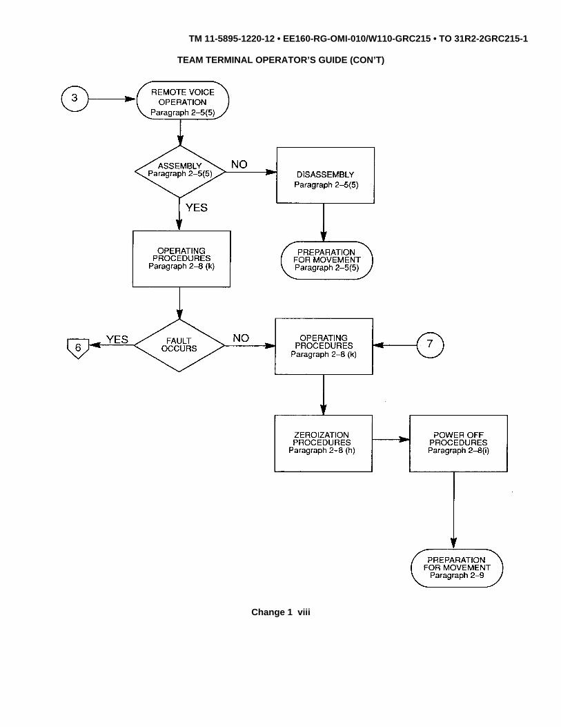
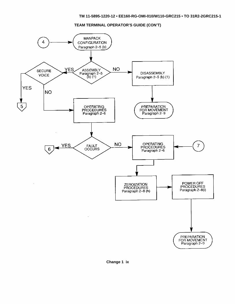
TEAM TERMINAL OPERATOR’S GUIDE (CON’T)
Change 1 vi

TM 11-5895-1220-12 • EE160-RG-OMI-010/W110-GRC215 • TO 31R2-2GRC215-1
TEAM TERMINAL OPERATOR’S GUIDE (CON’T)
Change 1 vii
TM 11-5895-1220-12 • EE160-RG-OMI-010/W110-GRC215 • TO 31R2-2GRC215-1
TEAM TERMINAL OPERATOR’S GUIDE (CON’T)
Change 1 viii
TM 11-5895-1220-12 • EE160-RG-OMI-010/W110-GRC215 • TO 31R2-2GRC215-1
TEAM TERMINAL OPERATOR’S GUIDE (CON’T)
Change 1 ix

TM 11-5895-1220-12 • EE160-RG-OMI-010/W110-GRC215 • TO 31R2-2GRC215-1
TEAM TERMINAL OPERATOR’S GUIDE (CON’T)
Change 1 x

TM 11-5895-1220-12 • EE160-RG-OMI-010/W110-GRC215 • TO 31R2-2GRC215-1
TEAM TERMINAL OPERATOR’S GUIDE (CON’T)
Change 1 xi

TM 11-5895-1220-12 • EE160-RG-OMI-010/W110-GRC215 • TO 31R2-2GRC215-1
RADIO SET AN/GRC-215
Change 2 1-0

TM 11-5895-1220-12 • EE160-RG-OMI-010/W110-GRC215 • TO 31R2-2GRC215-1
CHAPTER 1
INTRODUCTION
Subject Page
Equipment Description and Data.................................................................................................................................. 1-5General Information...................................................................................................................................................... 1-1Principles of Operation ................................................................................................................................................. 1-29
Section I. GENERAL INFORMATION
1-1. SCOPE
a. Type of Manual. Operator and Unit Maintenance Manual.
b. Model and Equipment Name. Radio Set AN/GRC-215
c. Purpose of Equipment. To provide a single high frequency (HF) communication (secure/nonsecure data andvoice) link with a Regency Net (RN) Force Terminal.
d. Maintenance Category Cross-reference. Army maintenance categories are referenced in this manual. Navyand Air Force personnel will contact their same-level maintenance group. Refer to the following cross-reference list.
Army Navy Air Force
Unit Organizational Organizational
1-2. CONSOLIDATED INDEX OF PUBLICATIONS AND BLANK FORMS
a. Army. Refer to the latest issue of DA Pam 25-30 to determine whether there are new editions, changes oradditional publications pertaining to the equipment.
b. Navy. Navy personnel refer to NAVSUP 2002.
c. Air Force. For technical publications, Air Force personnel refer to Numerical Index and Requirements Table(NI & RT). For non-technical publications, refer to AFR 0-2. For forms, refer to AFR 0-9.
1-1
TM 11-5895-1220-12 • EE160-RG-OMI-010/W110-GRC215 • TO 31R2-2GRC215-1
1-3. MAINTENANCE FORMS, RECORDS, AND REPORTS
a. Reports of Maintenance and Unsatisfactory Equipment. Department of the Army forms and procedures usedfor equipment maintenance will be those prescribed by DA Pam 738-750 as contained in Maintenance ManagementUpdate. Air Force personnel will use AFR 66-1 for maintenance reporting and TO 00-35D-54 for unsatisfactory equipmentreporting. Navy personnel will report maintenance performed utilizing the Maintenance Data Collection Subsystem(MDCS) IAW OPNAVINST 4790.4 Vol 13 and unsatisfactory material/conditions utilizing the PMS Feedback Report.
b. Report of Packaging and Handling Deficiencies. Fill out and forward SF 364 (Report of Discrepancy(ROD)) as prescribed in AR 735-11-2/DLAR 4140.55 SECNAVINST 4355.18/MCO 4430.3J.
c. Transportation Discrepancy Report (TDR) (SF 361). Fill out and forward Transportation Discrepancy Report(TDR) (DISREP) (SF 361) as prescribed in AR 55-38/NAVSUPINST 4610.33C/AFR 75-18/MCO 4610.19D/ DLAR4500.15.
1-4. HAND RECEIPT (-HR) MANUALS
This manual has a companion document with a TM number followed by "HR" (which stands for Hand Receipt).The TM 11-5895-1220-10-HR consists of preprinted hand receipts (DA Form 2062) that list end item related equipment(i.e. COEI, BII, and AAL) you must account for. As an aid to property accountability, additional -HR manuals may berequisitioned from the US Army Adjutant General Publications Center, Baltimore, MD, in accordance with the proceduresin Chapter 3, AR 310-2, and DA Pam 310-10-2.
1-5. REPORTING EQUIPMENT IMPROVEMENT RECOMMENDATIONS (EIR)
a. Army. If your equipment needs improvement, let us know. Send us an EIR. You, the user, are the only onewho can tell us what you don’t like about the design or performance. Put it on an SF 368 (Product Quality DeficiencyReport). Mail it to Commander, US Army Communications-Electronics Command and Fort Monmouth, ATTN: AMSEL-PA-MA-D, Fort Monmouth, New Jersey 07703-5000. We’ll send you a reply.
b. Navy. Navy personnel are encouraged to submit EIR’s through their local Beneficial Suggestion Program.
c. Air Force. Air Force personnel are encouraged to submit EIR’s in accordance with AFR 900-4.
1-6. ADMINISTRATIVE STORAGE
Administrative Storage of equipment issued to and used by Army activities will have preventive maintenanceperformed in accordance with the PMCS charts before storing. When removing the equipment from administrativestorage the PMCS should be performed to assure operational readiness. Disassembly and repacking of equipment forshipment or limited storage are covered in Chapter 4.
1-2

TM 11-5895-1220-12 • EE160-RG-OMI-010/W110-GRC215 • TO 31R2-2GRC215-1
1-7. DESTRUCTION OF ELECTRONICS MATERIEL
a. Army. Destroy Radio Set AN/GRC-215 in accordance with the procedures in TM 750-244-2 to preventenemy use.
b. Navy. Navy personnel comply with the local Command Material Destruction Plan.
c. Air Force. Air Force personnel comply with TM 750-244-2 or the local emergency destruction plan.
1-8. PREPARATION FOR STORAGE OR SHIPMENT
a. Army. Before placing equipment in administrative storage, insure tha equipment is operational. Ifoperational, put into storage using appropriate corrosion control techniques. When removing from storage, again performoperational tests and Unit PMCS (if available) to determine mission capability.
b. Navy. Refer to NAVSUP PUB 503.
c. Air Force. Refer to AFM 66-267 (storage) and AFR 67-31 (shipment).
1-9. NOMENCLATURE CROSS-REFERENCE LIST
COMMON NAME OFFICIAL NOMENCLATURE
Antenna Base Base, Antenna AB-1335/G
Antenna Cable Cable Assembly, RF CG-3873/GRC-215
Antenna Matching Capacitor Capacitor, A3086683
Antenna Tuning Unit (ATU) Coupler, Antenna CU-2351/GRC-215
ATU Control Cable Cable Assembly, Special Purpose,Electrical CX-13349/GRC-215
ATU Power Cable Cable Assembly, Power, ElectricalCX-13352/GRC-215
ATU Safety Cap Cap, Electrical A3172948
ECCM Module Controller, RT C-11670/G
Field Wire Telephone Cable WF-16/U
Handset Handset H-356/G
Headset Headset H-251/U
I/O Unit Input-Output Unit MX-10819/GRC-215
KG-84A Communications Security EquipmentTSEC/KG-84A
Change 2 1-3

TM 11-5895-1220-12 • EE160-RG-OMI-010/W110-GRC215 • TO 31R2-2GRC215-1AIR FORCE TO 31R2-2GRC215-1
1-9. NOMENCLATURE CROSS-REFERENCE LIST (Cont.)
COMMON NAME OFFICIAL NOMENCLATURE
KY-65A Speech Security Equipment TSEC/KY-65A
Manpack Whip Antenna Antenna AS-3805/GRC-215
Near Vertical Incident Antenna AS-2259/GRSkywave (NVIS) Antenna
NVIS Antenna Adapter Adapter, Antenna to AntennaBase MX-9313/GR
Power Amplifier (PA) Amplifier, Power AM-7301/GRC-215
Receiver-Transmitter (RT) Receiver-Transmitter, RadioRT-1511/GRC-215
Remote Cable Cable Assembly, Special Purpose,Electrical CX-13350/GRC-215
Remote Control Set Converter CV-3968/GRC-215
RF Cable Cable Assembly, Radio FrequencyCG-3872/GRC-215
RN Modem Modem, Digital Data MD-1204/G
Team Terminal (TT) Radio Set AN/GRC-215
Team Terminal Power Supply Power Supply PP-8170/GRC-215(TTPS)
Time of Day Transfer Cable, Cable Assembly, and Reel CG-3883/G(TOD Cable)
Time Standard Reference Oscillator, Frequency ReferenceFrequency Oscillator (RFO) O-1836/G
Vehicle Input Power Cable Cable Assembly, Power, ElectricalCX-13348/GRC-215
Vehicular Adapter (VA) Mounting Base, ElectricalEquipment MT-6452/GRC-215
Whip Antenna Antenna Assembly AS-3809/G
Z-AKE AC/DC Power Supply Z-AKE/TSEC
Z-AKG Battery Pack Assembly Z-AKG/TSEC
230 VAC Pwr Input Cable Cable Assembly, Pwr CX-13372/GRC-215
115 VAC Pwr Input Cable Cable Assembly, Pwr CX-13373/GRC-215
Change 1 1-4

TM 11-5895-1220-12 • EE160-RG-OMI-010/W110-GRC215 • TO 31R2-2GRC215-1
1-10. LIST OF ABBREVIATIONS
Refer to the glossary at the back of this manual for a list of abbreviations and definition of unusual terms.
Section II. EQUIPMENT DESCRIPTION AND DATA
1-11. EQUIPMENT CHARACTERISTICS, CAPABILITIES, AND FEATURES
a. Characteristics. The Team Terminal is a HF radio set. It is normally mounted on a vehicle. It can operatewhile in motion or at a halt. The Team Terminal features a Manpack capability for radio operation away from the vehicle.The Manpack is a HF radio set which can be operated in either secure or nonsecure voice mode of operation.
b. Capabilities and Features.
(1) Team Terminal.
• One HF transmit/receive channel
• Frequency range: 2.0000 to 29.9999 MHz
• Power output (selectable): 5, 25, or 100 Watts
• Data or voice modes (secure or nonsecure)
• ECCM capable
• Remoteable via the Remote Control Set (voice only)
• Input voltage +12/+24 Vdc or 115/230 Vac compatibility
(2) Manpack.
• One HF transmit/receive channel
• Frequency range: 2.0000 to 29.9999 MHz
• Power output (selectable): 5 or 25 Watts
• Voice mode (secure or nonsecure)
• ECCM capable
• Input voltage +24 Vdc compatibility
1-5

TM 11-5895-1220-12 • EE160-RG-OMI-010/W110-GRC215 • TO 31R2-2GRC215-1
1-12. LOCATION AND DESCRIPTION OF MAJOR COMPONENTS
a. Team Terminal.
RACK MOUNTED COMPONENTS
All operating components except the ATU, Remote Control Set, and antennas are housed in a rack/palletassembly (rack). The rack is normally installed in a vehicle. The COMSEC equipments, TSEC/KG-84A andTSEC/KY-65A, are furnished separately.
1-6

TM 11-5895-1220-12 • EE160-RG-OMI-010/W110-GRC215 • TO 31R2-2GRC215-1
1-12. LOCATION AND DESCRIPTION OF MAJOR COMPONENTS (Cont.)
RACK MOUNTED COMPONENTS (Cont.)
1-7

TM 11-5895-1220-12 • EE160-RG-OMI-010/W110-GRC215 • TO 31R2-2GRC215-1
1-12. LOCATION AND DESCRIPTION OF MAJOR COMPONENTS (Cont.)
I/O UNIT
The I/O Unit provides the capability to transmit and receive Regency Net messages. It manages, maintains andcontrols the operating modes of the Team Terminal. The I/O Unit consists of a removable display/keypad (D/K) assemblyand the controller assembly. These assemblies are connected by the remote cable to allow the D/K assembly to bemounted in the rack with the controller assembly or mounted separately (via a 20-foot remote cable) in a position moreconvenient to the operator.
1-8

TM 11-5895-1220-12 • EE160-RG-OMI-010/Wll0-GRC-215 • TO 31R2-2GRC215-1
1-12. LOCATION AND DESCRIPTION OF MAJOR COMPONENTS (Cont.)
The D/K assembly provides operator interface. It displays menus in response to operational sequences. The D/Kassembly is also used to compose and view messages, perform network communications and for initiating BIT.
CONTROLLER ASSEMBLY
Controller assembly functions include network management and communications and control of the HFequipment.
1-9

TM 11-5895-1220-12 • EE160-RG-OMI-010/Wll0-GRC-215 • TO 31R2-2GRC215-1
1-12. LOCATION AND DESCRIPTION OF MAJOR COMPONENTS (Cont.)
The RT is a single-sideband (SSB) receiving and transmitting unit. The RT comprises the receiver/exciter (R/E)and the ECCM Module. Functional capabilities include:
• Frequency range - 2.0000 to 29.9999 MHz
• Number of possible channels - 280,000
• Output power - 5 Watts, 100 Watts (when used as Team Terminal), 5 Watts, 25 Watts (when used asManpack)
• Modes - ECCM, non-ECCM, upper sideband (USB)/lower sideband (LSB), data and voice
• Removable from rack for use as part of Manpack
1-10

TM 11-5895-1220-12 • EE160-RG-OMI-010/Wll0-GRC-215 • TO 31R2-2GRC215-1
1-12. LOCATION AND DESCRIPTION OF MAJOR COMPONENTS (Cont.)
R/T (Cont.)
R/E
The R/E is controlled by the ECCM Module which plugs into and becomes an integral part of the R/E. All radiofunctions including operating frequency and power level are selected by means of the I/O Unit D/K assembly or the keypadon the ECCM Module front panel (depending on configuration).
ECCM MODULE
The ECCM Module provides data and voice ECCM capabilities. It is the operator interface for Manpackoperations. It controls the frequency synthesizer (high speed synthesizer) contained in the Vehicular Adapter, the PA andthe ATU. The ECCM Module contains self-test features.
1-11

TM 11-5895-1220-12 • EE160-RG-OMI-010/Wll0-GRC-215 • TO 31R2-2GRC215-1
1-12. LOCATION AND DESCRIPTION OF MAJOR COMPONENTS (Cont.)
VEHICULAR ADAPTER
The Vehicular Adapter provides:
• Mounting for the RT and the Battery Case/Charger.
• Automatic charging of the Battery Case/Charger.
• A charger cable for charging the Remote Control Set batteries.
• Contains the high speed synthesizer.
• Routing of signals to/from the high speed synthesizer, the RT, ATU, and PA.
1-12

TM 11-5895-1220-12 • EE160-RG-OMI-010/Wll0-GRC-215 • TO 31R2-2GRC215-1
1-12. LOCATION AND DESCRIPTION OF MAJOR COMPONENTS (Cont.)
PA
The PA amplifies the transmit radio frequency (RF) signal from the RT. Functional capabilities include:
• 10 Watt input - 25 or 100 Watt output
• When bypassed - 5 Watt input, 5 Watt output
• BIT
TT PS
The TT PS converts ac or dc input power to a regulated dc output:
• Input: 115/230 Vac, single phase, 50/60 Hz or +12/+24 Vdc.
• Output: +28 Vdc at 24 amperes and +8.5 Vdc at 3 amperes.
1-13

TM 11-5895-1220-12 • EE160-RG-OMI-010/Wll0-GRC-215 • TO 31R2-2GRC215-1
1-12. LOCATION AND DESCRIPTION OF MAJOR COMPONENTS (Cont.)
RFO
The RFO provides a reliable, real-time clock for the system. Functional capabilities include:
• Battery back-up; contains rechargeable batteries to provide for continuous operation through transientpower interruptions.
• Receipt of time from other time standard equipment.• Provides 10 MHz reference
RN MODEM
The RN Modem provides the frequency shift key (FSK) modulator-demodulator functions, and modem features. Italso interfaces with the TSEC/KG-84A for data input-output and with the RT for message reception and transmission.
1-14

TM 11-5895-1220-12 • EE160-RG-OMI-010/Wll0-GRC-215 • TO 31R2-2GRC215-1
1-12. LOCATION AND DESCRIPTION OF MAJOR COMPONENTS (Cont.)
TSEC/KG-84A
The TSEC/KY-65Aencrypts and decrypts voice traffic. AC/DC Power Supply Z-AKE powers TSEC/KY-65Awhen inthe vehicular configuration. Battery Pack Assembly Z-AKG powers TSEC/KY-65Awhen in the manpack configuration.
1-15
TM 11-5895-1220-12 • EE160-RG-OMI-010/Wll0-GRC-215 • TO 31R2-2GRC215-1
1-12. LOCATION AND DESCRIPTION OF MAJOR COMPONENTS (Cont.)
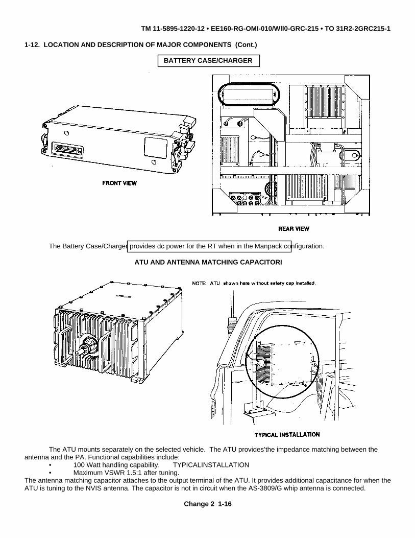
BATTERY CASE/CHARGER
The Battery Case/Charger provides dc power for the RT when in the Manpack configuration.
ATU AND ANTENNA MATCHING CAPACITORI
The ATU mounts separately on the selected vehicle. The ATU provides’the impedance matching between theantenna and the PA. Functional capabilities include:
• 100 Watt handling capability. TYPICALINSTALLATION• Maximum VSWR 1.5:1 after tuning.
The antenna matching capacitor attaches to the output terminal of the ATU. It provides additional capacitance for when theATU is tuning to the NVIS antenna. The capacitor is not in circuit when the AS-3809/G whip antenna is connected.
Change 2 1-16

TM 11-5895-1220-12 • EE160-RG-OMI-010/Wll0-GRC-215 • TO 31R2-2GRC215-1
1-12. LOCATION AND DESCRIPTION OF MAJOR COMPONETS (Cont.)
The ATU Safety Cap is a cone shaped nylon insulator which attaches to the ATU. It protects personnel from directphysical contact with the tip of the ATU tuning capacitor assembly during operation. The Safety Cap covers the entireantenna matching capacitor and is provided with access slots to facilitate connection of antenna cable W1.
Change 2 1-16.1/(1-16.2 blank)

TM 11-5895-1220-12 • EE160-RG-OMI-010/Wll0-GRC-215 • TO 31R2-2GRC215-1
1-12. LOCATION AND DESCRIPTION OF MAJOR COMPONENTS (Cont.)
Antenna Assembly AS-3809/G (Whip Antenna) has a frequency range of 2.00 to 29.99 MHz. It consists of four 4-foot sections and Base, Antenna AB-1335/G (Antenna Base). The antenna insulator boot (not part of the Whip Antenna)fits over the Antenna Base to protect personnel from direct contact with the Whip Antenna and possible serious injury.
Antenna AS-2259/GR (NVIS Antenna) is stored in a canvas storage pack when not in use. The NVIS Antenna isused to enhance communications in the skip zone. The NVIS Antenna provides high-angle radiation (near verticalincidence) to permit short-range skywave propagation over communication circuits varying from 0 - 300 miles. The NVISAntenna has a limited frequency range of 2 to 20 MHz. The NVIS Antenna is mounted on the Antenna Base using Adapter,Antenna to Antenna Base MX-9313/GR (NVIS Antenna Adapter).
Antenna AS-3805/GRC-215 (Manpack Whip Antenna)consists of eight sections and has a frequency range of 2.00 to29.99 MHz.
1-17

TM 11-5895-1220-12 • EE160-RG-OMI-010/Wll0-GRC-215 • TO 31R2-2GRC215-1
1-12. LOCATION AND DESCRIPTION OF MAJOR COMPONETS
b. Manpack Radio
The Manpack provides single channel HF secure or nonsecure voice communications. It enables the TeamTerminal operator to leave the vehicle and maintain voice communications at reduced power. The Manpack is assembledusing the RT (comprised of R/E and ECCM Module), Battery Case/Charger, Manpack Whip Antenna, Handset andcarrying harness. When in the secure mode, the TSEC/KY-65 is removed from the rack and connected to the Manpackvia hard-wire.
1-18

TM 11-5895-1220-12 • EE160-RG-OMI-010/Wll0-GRC-215 • TO 31R2-2GRC215-1
1-12. LOCATION AND DESCRIPTION OF MOJOR COMPONETS (Cont.)
The Remote Control Set provides remote operation of the Team Terminal. It consists of the R/E terminal and theremote location. When deployed, the R/E terminal is interchanged with the ECCM Module of the RT and then the R/Eterminal and remote location are connected via field wire.
• R/E Terminal - Provides signal and control interfaces between the R/E and remote location.
• Remote Location - Provides battery power for the ECCM Module and signal/control interfaces between theR/E terminal and ECCM Module.
1-19

TM 11-5895-1220-12 • EE160-RG-OMI-010/Wll0-GRC-215 • TO 31R2-2GRC215-1
1-13. EQUIPMENT DATA
a. Team Terminal.
(1) Power Consumption
TRANSMIT RECEIVE
I/O Unit ........................ ............................................................................................... 88 88 WattsRT ............................................................................................................................... 20 4 WattsVehicular Adapter ....................................................................................................... 44 44 WattsPA ............................................................................................................................... 350 10 WattsTSEC/KY-65 ............................................................................................................... 40 40 WattsTSEC/KG-84A ..................... ....................................................................................... 15 15 WattsTT PS ........................... .............................................................................................. 167 78 WattsRN Modem ....................... .......................................................................................... 52 52 WattsRFO ............................................................................................................................ 34 34 WattsATU ............................. ............................................................................................... 25 25 Watts
(2) Weights and Dimensions
Rack Assembly (without rack-mounted components):
Weight ......................................................................................................................... 120 lbLength.......................................................................................................................... 22 inWidth ........................................................................................................................... 38 inHeight ......................................................................................................................... 33.8 in
Rack Assembly (with rack-mounted components):
Weight ........................................................................................................................ 450 lb
I/O Unit:
Weight ........................................................................................................................ 58 lbLength.......................................................................................................................... 19.5 inWidth ........................................................................................................................... 17.1 inHeight .......................................................................................................................... 12.9 in
RT:
Weight ......................................................................................................................... 18 lbLength ......................................................................................................................... 9.4 inWidth ........................................................................................................................... 12.2 inHeight .......................................................................................................................... 5.9 in
Battery Case/Charger:
Weight ......................................................................................................................... 7.0 lbLength.......................................................................................................................... 5.9 inWidth ........................................................................................................................... 12.2 inHeight .......................................................................................................................... 3.1 in
1-20

TM 11-5895-1220-12 • EE160-RG-OMI-010/Wll0-GRC-215 • TO 31R2-2GRC215-1
1-13. EQUIPMENT DATA (Cont.)
Vehicular Adapter:
Weight ............................................................................................................................................ 25 lbLength.............................................................................................................................................. 15.75 inWidth .............................................................................................................................................. 12.2 inHeight ............................................................................................................................................. 7.09 in
PA:
Weight ............................................................................................................................................ 19 lbLength.............................................................................................................................................. 13.7 inWidth ............................................................................................................................................... 5.0 inHeight ............................................................................................................................................. 7.76 in
TSEC/KY-65 (with Battery Pack):
Weight ............................................................................................................................................ 24.5 lbLength.............................................................................................................................................. 16.1 inWidth ............................................................................................................................................... 11.3 inHeight .............................................................................................................................................. 4.8 in
TSEC/KG-84A:
Weight ............................................................................................................................................ 20 lbLength.............................................................................................................................................. 15.2 inWidth ............................................................................................................................................... 7.5 inHeight .............................................................................................................................................. 7.8 in
TT PS:
Weight ............................................................................................................................................. 62 lbLength.............................................................................................................................................. 14.9 inWidth ............................................................................................................................................... 15.1 inHeight .............................................................................................................................................. 6.8 in
RN Modem:
Weight ............................................................................................................................................. 25 lbLength.............................................................................................................................................. 16 inWidth ............................................................................................................................................... 7.5 inHeight .............................................................................................................................................. 6.75 in
RFO:
Weight ............................................................................................................................................ 33 lbLength.............................................................................................................................................. 15.5 inWidth ............................................................................................................................................... 9.5 inHeight .. ........................................................................................................................................... 6.8 in
1-21

TM 11-5895-1220-12 • EE160-RG-OMI-010/Wll0-GRC-215 • TO 31R2-2GRC215-1
1-13. EQUIPMENT DATA (Cont.)
ATU (externally mounted):
Weight ......................................................................................................................... 46.2 lbLength............................................................................................................................ 22.6 inWidth ............................................................................................................................. 13.5 inHeight ........................................................................................................................... 8.38 in
Cabling ......................................................................................................................... 35.0 lb
Misc. Hardware ............................................................................................................. 3.5 lb
(3) Power Requirements
Input Voltage ................................................................................................................. 115 Vac 50/60 Hz.......................................................................................................................................230 Vac 50/60 Hz
Vehicle Batteries ........................................................................................................... +12/+24 Vdc
b. Manpack.
(1) Weights and Dimensions
Manpack (RT and Battery Case/Charger):
Weight .......................................................................................................................... 25 lbLength............................................................................................................................ 15.3 inWidth ............................................................................................................................. 12.2 inHeight ............................................................................................................................ 5.9 in
TSEC/KY-65 (with TSEC/KY-65 Battery Pack):
Weight .......................................................................................................................... 24.5 lbLength............................................................................................................................ 16.1 inWidth ............................................................................................................................. 11.3 inHeight ............................................................................................................................ 4.8 in
(2) Power Requirements:
Input Voltage:
Battery BB-590/U (or Battery BA-5590/U) - three used (two in Battery Case/Chargerand one in Remote Control Set) ................................................................................... +24 Vdc
Battery operation subject to the following limitations:
-300F (-340C) and above: ............................................................................................approximately 20 hours-310F (-340C) and below: ............................................................................................approximately 10 hours.
1-22

TM 11-5895-1220-12 • EE160-RG-OMI-010/Wll0-GRC-215 • TO 31R2-2GRC215-1
1-13. EQUIPMENT DATA (Cont.)
c. Remote Control Set:
Separation distance Up to 1 mile
Remote Location:Length................................ ...................................................................................... 3.1 inWidth................................ ........................................................................................ 11 inHeight ....................................................................................................................... 7.6 in
R/E Terminal:Length ............................... ...................................................................................... 3.1 inWidth... ..................................................................................................................... 5.1 inHeight ....................................................................................................................... 5.5 in
1-23

TM 11-5895-1220-12 • EE160-RG-OMI-010/Wll0-GRC-215 • TO 31R2-2GRC215-1
1-14. EQUIPMENT CONFIGURATION
a. Vehicular Configuration. The Team Terminal provides voice or data communications for operations while inmotion or at halt. When in motion, the Whip Antenna is used. At halt, the Whip Antenna is normally used or can bereplaced by the NVIS Antenna. The rack assembly accommodates installation and use in a wide variety of vehicles(typical installation shown below). All controls are accessible from the front of the rack.
VEHICULAR CONFIGURATION
Change 2 1-24

TM 11-5895-1220-12 • EE160-RG-OMI-010/Wll0-GRC-215 • TO 31R2-2GRC215-1
1-14. EQUIPMENT CONFIGURATION (Cont.)
b. Vehicular Remote Configurations. The Team Terminal can be configured for remote data operations or remotevoice operations. During remote data operations, the D/K assembly is placed away from the rack assembly for operatorconvenience, via a 20-foot remote cable. During remote voice operations, the ECCM Module is placed away from thevehicle via the Remote Control Set (includes R/E terminal and remote location). This is accomplished by interchanging theECCM Module and R/E terminal and connecting the two units via field wire (up to 1 mile).
VEHICULAR REMOTE CONFIGURATIONS
1-25

TM 11-5895-1220-12 • EE160-RG-OMI-010/Wll0-GRC-215 • TO 31R2-2GRC215-1
1-14. EQUIPMENT CONFIGURATION (Cont.)
c. Manpack Configuration. The Team Terminal equipment configuration allows rapid reconfiguration for Manpackoperations. This enables the operator to leave the vehicle and maintain secure/nonsecure voice communications. TheManpack consists of the RT fastened to the Battery Case/Charger with the Manpack Whip Antenna and Handsetconnected to the RT front panel. This equipment fits into a carrying harness for Manpack use. For secure voice operation,the TSEC/KY-65 is removed from the equipment rack and its AC/DC Power Supply is replaced with KY-65 Battery Pack Z-AKG and hard- wired to the Manpack.
MANPACK
MANPACK CONFIGURATION WITH TSEC/KY-65A
1-26

TM 11-5895-1220-12 • EE160-RG-OMI-010/Wll0-GRC-215 • TO 31R2-2GRC215-1
1-15. SAFETY, CARE, AND HANDLING
CAUTION
Prior to removing or installing a component or cable, ensure that power to the component has been turnedoff. Removing and connecting cables while power is applied may result in an arc or short. This canproduce damage to the connector pins.
a. Make all cable connections by hand. Do not use tools. When tools are used to make connections, connectorsmay be over tightened and damage to the connector and pins may occur.
b. Some component weight limits are greater than one person lift. When removing/installing components, observepersonnel lift warnings marked on equipment labels and stated in this manual. Always use equipment handles when lifting.Improper lifting may cause injury to personnel.
c. Do not install the antenna where it may come in contact with a structure or material which will cause the radiofrequency (RF) signal to be shorted to ground. Damage to the equipment may occur.
CAUTION
This equipment contains certain static-sensitive solid state devices which are subject to damage fromelectrostatic discharge. Effective control of electrostatic discharge is maintained only through continuousstrict observance of the following maintenance procedures:
• Any maintenance requiring disassembly of the equipment must be performed at an approvedwork station. The work station must include a grounded surface and grounded wrist strap inaccordance with DOD-HDBK-263.
• All maintenance personnel must have completed training in the handling of static-sensitivedevices before working on this equipment. Maintenance personnel must wear the grounded wriststrap and be at an approved work station when performing maintenance.
• The static sensitive subassemblies or circuit cards must be stored in approved electrostatic freematerial when not installed in the equipment.
1-27

TM 11-5895-1220-12 • EE160-RG-OMI-010/Wll0-GRC-215 • TO 31R2-2GRC215-1
TEAM TERMINAL FUNCTION BLOCK DIAGRAM
1-28

TM 11-5895-1220-12 • EE160-RG-OMI-010/Wll0-GRC-215 • TO 31R2-2GRC215-1
Section III. PRINCIPLES OF OPERATION
1-16. GENERAL
The Team Terminal is an element of the Regency Net (RN) communications system. Within the RN system, the TeamTerminal is the final link in communications from the Network Control Station (NCS). Team Terminals are assignedcommunication links with individual Force Terminals. Secure or nonsecure voice and data communications are facilitatedwith a single HF radio set, and use of a whip antenna via ground wave propagation. During poor HF propagationconditions, an NVIS antenna is used to provide short-range skywave propagation over communication circuits varying from0 to 300 miles. Radio and voice encryption equipment may be removed from the rack assembly in order to provideManpack voice communications. The block diagram illustrates the functions of the Team Terminal. Items identified withcrosshatching are used for the manpack configuration.
1-17. FUNCTIONAL DESCRIPTION
a. Team Terminal. All automatic functions within the Team Terminal are controlled by the I/O Unit through thecontrol bus. The RT (includes the R/E and the ECCM Module) utilizes a known time of day (TOD) from the RFO to selectthe receive and transmit frequencies for ECCM operation. The TOD is loaded into the RFO through an external TODinterface. The RFO also provides a 10 MHz reference frequency standard for the RN Modem and the high speedsynthesizer, contained in the Vehicular Adapter. Transmit/receive (TX/RX) data from/to the I/O Unit passes through theTSEC/KG-84A and RN Modem to/from the ECCM Module. The PA amplifies the transmit RF signal from the R/E. TheATU couples the output of the PA to the antenna. The Vehicular Adapter serves as a mount for the RT and BatteryCase/Charger. The vehicular Adapter also interfaces control signals from the RT to the PA and ATU and charges thebatteries in the Battery Case/Charger. The voice interface is provided through the Handset. Audio is routed through theTSEC/KY-65Afor encryption/decryption. The sync voice interface from the ECCM Module activates the TSEC/KY-65A.The TT PS provides +28 and +8.5 Vdc for system components. Input power to the TT PS can be from a vehicular powersource of +12/+24 Vdc or from an ac power source of 115/230 Vac. A signal flow description for the following is provided.
• Voice signal flow
• Data signal flow
• Data signal flow with D/K assembly remoted
• Voice signal flow using Remote Control Set
1-29

TM 11-5895-1220-12 • EE160-RG-OMI-010/Wll0-GRC-215 • TO 31R2-2GRC215-1
1-17. FUNCTIONAL DESCRIPTION (Cont.)
(1) Voice Signal Flow. The block diagram shows the Team Terminal secure voice signal flow. The HF signalis received on the antenna and is passed through the ATU to the PA. The PA filters the HF signal andapplies it to the R/E. Within the R/E, the HF signal is filtered again and demodulated. The audio output isrouted through the ECCM Module to the TSEC/KY-65A to make the secure voice nonsecure. Thenonsecure voice from the TSEC/KY-65A is routed back to and through the ECCM Module and applied tothe Handset. Secure voice transmission follows a reversed receive signal flow. Clear voice from theHandset is routed through the ECCM Module to the TSEC/KY-65A to make non-secure voice secure. Thesecure voice is routed back to and through the ECCM Module to the R/E. The R/E modulates the securevoice and converts it into an HF signal. The HF signal is then routed to the PA. The PA amplifies the HFsignal before sending it on to the ATU. The ATU matches the input impedance of the antenna to theoutput impedance of the PA. The HF signal is then radiated out via the antenna. Nonsecure voicecommunications follow the same signal flow with theTSEC/KY-65A bypassed. The TSEC/KY-65A can bebypassed by placing the TSEC/KY-65A MODE switch in the PLAIN position.
TEAM TERMINAL VOICE SIGNAL FLOW
1-30

TM 11-5895-1220-12 • EE160-RG-OMI-010/Wll0-GRC-215 • TO 31R2-2GRC215-1
1-17. FUNCTIONAL DESCRIPTION (Cont.)
(2) Data Signal Flow. The block diagram shows the Team Terminal data signal flow. The HF signal from theantenna passes through the ATU and the PA to the R/E. The R/E demodulates the HF signal and turns itinto audio tones. The RN Modem converts the audio tones into digital data. The resulting digital data isapplied to the TSEC/KG-84A to make the secure data nonsecure. The nonsecure data is passed on to theI/O Unit where it is seen as a displayed message. The I/O Unit dictates operating modes, messagereception and transmission sequences, and BIT operations. Messages for transmission are generated bythe operator via the I/O Unit. Specific text or status messages are formatted by the I/O Unit and routed tothe TSEC/KG-84A to be made secure. The TSEC/KG-84A outputs the secure data to the RN Modem. TheRN Modem formats the secure data and converts it to audio tones. The audio tones are applied to andthrough the ECCM Module to the R/E. The R/E modulates the audio tones and converts them into an HFsignal. The HF signal is then routed through the PA for amplification and then sent to the ATU. The ATUmatches the antenna impedance with the output impedance of the PA. The HF signal is radiated out viathe antenna.
1-31

TM 11-5895-1220-12 • EE160-RG-OMI-010/Wll0-GRC-215 • TO 31R2-2GRC215-1
1-17. FUNCTIONAL DESCRIPTION (Cont.)
DATA SIGNAL FLOW WITH D/K ASSEMBLY REMOTED
(3) Data Signal Flow with D/K Assembly Remoted. The block diagram shows the data signal flow with the D/Kassembly remoted. The D/K assembly interfaces with the controller assembly through a remote cable. Thedata signal flow from the controller assembly to the antenna is the same as it is when in the normalvehicular configuration.
VOICE SIGNAL FLOW USING REMOTE CONTROL SET
(4) Voice Signal Flow Using the Remote Control Set. The Remote Control Set includes the R/E terminal andthe remote location. In this configuration, the ECCM module is removed from the R/E and connected tothe remote location. The R/E terminal is removed from the remote location and connected to the R/E. TheR/E terminal and the remote location are then connected via field wire. The ECCM Module front panelcontrols allow the operator to select channel frequency and communication mode. The voice signal flowfrom the R/E to the antenna is the same as it is when in the normal vehicular configuration.
1-32

TM 11-5895-1220-12 • EE160-RG-OMI-010/Wll0-GRC-215 • TO 31R2-2GRC215-1
1-17. FUNCTIONAL DESCRIPTION (Cont.)
b. Manpack.
(1) Capabilities. The Manpack is a single channel HF radio capable of secure or nonsecure voicecommunications. The Manpack consists of the RT (which includes the R/E and ECCM Module) fastenedto the Battery Case/Charger. For secure voice communications, the TSEC/KY-65A is removed from therack assembly and wired to the RT.
(2) Voice Signal Flow. During reception, the R/E filters and demodulates the HF signal from the ManpackWhip Antenna and provides audio output. The ECCM Module front panel controls allow the operator toselect channel frequency and communication mode. When in the secure voice mode, the audio out put isapplied to the TSEC/KY-65A to make the secure voice nonsecure. The TSEC/KY-65A nonsecure voiceoutput is routed back through the ECCM Module to the Handset. Voice transmission from the Handset isapplied to the TSEC/KY-65A to make the nonsecure voice secure. The TSEC/KY-65A secure voice outputis sent to the R/E. The R/E modulates the secure voice and converts it into an HF signal. The HF signal isamplified and applied to the Manpack Whip Antenna. Nonsecure voice communication is achieved byplacing the TSEC/KY-65A in the PLAIN mode or by disconnecting the TSEC/KY-65A from the RT andconnecting the handset directly to the ECCM Module AUDIO connector.
MANPACK VOICE FLOW
1-33

TM 11-5895-1220-12 • EE160-RG-OMI-010/Wll0-GRC-215 • TO 31R2-2GRC215-1
1-18. FUNCTIONAL DESCRIPTION OF COMPONENTS
This paragraph provides a brief functional description of Team Terminal components. For a more detailedfunctional description of components, refer to the component technical manual as applicable (refer to Appendix A,References).
a. RT. The RT is a single-sideband (SSB), receiving and transmitting unit. It operates in a frequency band of2.0000 to 29.9999 MHz. The RT consists of the R/E and the ECCM Module. The ECCM Module connects to the R/E. Allradio functions, including operating frequency and power level are selected by means of the D/K assembly or the keypadon the ECCM Module front panel.
(1) In the receive mode, the RT filters incoming RF signals and demodulates them to audio signals.The audio signals are amplified and then supplied to the RN Modem, voice decryption equipment,or to the Handset.
(2) In the transmit mode, the RT accepts audio signals from the RN Modem, voice encryptionequipment or the handset and modulates an RF carrier with them. The modulated RF signal isthen translated to the desired operating frequency and amplified. When operating with the WhipAntenna, the RT also provides tuning information to the ATU.
b. I/O Unit. The I/O Unit allows the operator to transmit and receive data messages. It controls the operatingmodes of the Team Terminal. The I/O Unit consists of the controller assembly and the D/K assembly. These assembliesare connected by a cable to allow the D/K assembly to be mounted in the rack assembly or separately in a position moreconvenient to the operator.
(1) All control and data entries are made via 34 bezel keys and 66 transparent screen overlayswitches (referred to as touchpoints). Menus and message prompts guide the operator to performthe following:
• Enter Team Terminal operating parameters.
• Initiate message transmission.
• Display received messages.
• Perform off-line BIT.
1-34
TM 11-5895-1220-12 • EE160-RG-OMI-010/W110-GRC-215 •TO 31R2-2GRC215-1
1-18. FUNCTIONAL DESCRIPTION OF COMPONENTS (Cont.)
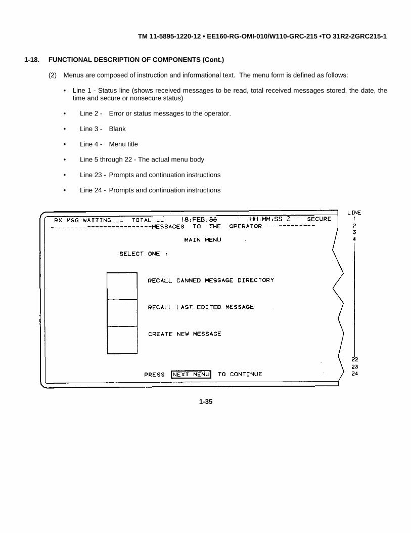
(2) Menus are composed of instruction and informational text. The menu form is defined as follows:
• Line 1 - Status line (shows received messages to be read, total received messages stored, the date, thetime and secure or nonsecure status)
• Line 2 - Error or status messages to the operator.
• Line 3 - Blank
• Line 4 - Menu title
• Line 5 through 22 - The actual menu body
• Line 23 - Prompts and continuation instructions
• Line 24 - Prompts and continuation instructions
1-35

TM 11-5895-1220-12 • EE160-RG-OMI-010/W110-GRC-215 •TO 31R2-2GRC215-1
1-18. FUNCTIONAL DESCRIPTION OF COMPONENTS (Cont.)
c. Vehicular Adapter. The Vehicular Adapter functions primarily as a mount for the RT when in the vehicularconfiguration. It inter-faces the RT to the PA and ATU. Additionally, this unit supports the high speed synthesizer used inall modes when in the vehicular configuration except when using the Remote Control Set. The Battery Case/Chargermounts on the rear of the Vehicular Adapter. The power which energizes the Battery Case/Charger is routed through theVehicular Adapter. The Vehicular Adapter also provides a means of charging the battery in the Remote Control Set.
d. PA. This unit amplifies the transmit signal from the RT. It receives a 10-watt RF input from the RT. It thenamplifies, filters, and routes it to the ATU. The PA sends BIT status signals back to the RT for transfer to the I/O Unit. Thepower output is selectable for 5, 25, or 100 watts via the I/O Unit or the ECCM Module; it also filters receive signals.
e. RFO. The RFO provides a reliable, real-time clock for the system. It provides a reference 10 MHz frequencystandard to the RN Modem and high speed fast synthesizer located in the Vehicular Adapter. When Time Of Day (TOD)has been correctly transferred into the RFO, and as long as power is maintained, the RFO will maintain TOD accuracy forapproximately 90 days before requiring an update. The RFO contains a rechargeable battery for operation during shortterm power interruptions (nominal 30 minutes).
f. TT PS. The TT PS provides +28 and +8.5 Vdc power to the Team Terminal equipment. It operates from 115/230Vac, 50/60 Hz or +12/24 Vdc. It has lighting and electromagnetic pulse (EMP) protection at both ac and dc input lines. Theoutput is current limited. It has over-voltage and over-temperature protection. The supply shuts down if the +28 Vdc outputvoltage exceeds +32.2 Vdc.
g. RN Modem. During transmit, the RN Modem converts digital data from the D/K assembly to analog for modulatingthe transmitter. In the receive mode, the demodulated analog signals from the RT are converted to digital data and routedto the D/K assembly. The RN Modem is microprocessor controlled and it maintains constant interface with the ECCMmodule.
h. ATU. This unit couples the output of the PA to the antenna. It compensates for the antenna reactive impedanceby matching the antenna impedance with the PA output impedance.
i. Battery/Case Charger. This unit holds the batteries used for Manpack operations and the battery charger.
j. Remote Control Set. This unit provides remote control operation of the Team Terminal (voice only).
Change 1 1-36

TM 11-5895-1220-12 • EE160-RG-OMI-010/W110-GRC-215 •TO 31R2-2GRC215-1
CHAPTER 2
OPERATING INSTRUCTIONS
SUBJECT PAGE
Description and Use of Operator’s Controls and Indicators ......................................................................................... 2-1Operator Preventive Maintenance Checks and Services (PMCS)............................................................................... 2-30Operation Under Usual Conditions............................................................................................................................... 2-34
Assembly and Preparation for Use-Vehicular Configuration........................................................................... 2-34Installation of TSEC/KY-65A,TSEC/KG-84A................................................................................ 2-34,2-38KG-84A Nonsecure Bypass Hookup.................................................................................................. 2-40Configure for Remote Data, Voice Operation .............................................................................. 2-42,2-44Installation of Whip, NVIS Antenna .............................................................................................. 2-48,2-49
Assembly and Preparation for Use-Manpack Configuration ........................................................................... 2-50Configure Manpack ............................................................................................................................ 2-50Configure Manpack for Secure Voice Operation................................................................................ 2-54
Manpack Operating Procedures...................................................................................................................... 2-56Turn-On Procedures .......................................................................................................................... 2-56Selecting Frequencies for Manpack................................................................................................... 2-59Loading Preset Channels into Manpack............................................................................................. 2-61Fine Tuning the Manpack................................................................................................................... 2-63Changing Sidebands for the Manpack ............................................................................................... 2-64Selecting Power Output for the Manpack........................................................................................... 2-65Enable/Disable Manpack ECCM Mode .............................................................................................. 2-66Changing/Loading TRANSEC Variables-Manpack ............................................................................ 2-67Enable/Disable Manpack Secure Voice Mode ................................................................................... 2-68
Initial Adjustments, Daily Checks, and Self-Test............................................................................................. 2-69Team Terminal Operating Procedures ............................................................................................................ 2-69
Power-On Sequence .......................................................................................................................... 2-70Initialization......................................................................................................................................... 2-75Message Creation and Handling........................................................................................................ 2-106Show Message................................................................................................................................... 2-112Operational Setup .............................................................................................................................. 2-114Changing TRANSEC Variables.......................................................................................................... 2-116Leave Net Procedure ......................................................................................................................... 2-117Zeroization Procedure ........................................................................................................................ 2-119Power-Off Sequence .......................................................................................................................... 2-120Remote Data, Voice Operation .................................................................................................... 2-121,2-123
Preparation for Movement............................................................................................................................... 2-125Decals and Instruction Plates.......................................................................................................................... 2-127
Operation Under Unusual Conditions........................................................................................................................... 2-131Operation in Unusual Weather, Emergency, and NBC Procedures................................................................ 2-131Jamming and ECCM Procedures.................................................................................................................... 2-132
Section I. DESCRIPTION AND USE OF OPERATOR'S CONTROLS AND INDICATORS
2.1 GENERAL
Description and use of controls and indicators for TSEC/KG-84A and TSEC/KY-65A are not covered in thismanual. Refer to TM 11-5810-308-12&P and TM 11-5810-280-12&P, respectively.
Change 1 2-1
TM 11-5895-1220-12 • EE160-RG-OMI-010/W110-GRC-215 •TO 31R2-2GRC215-1
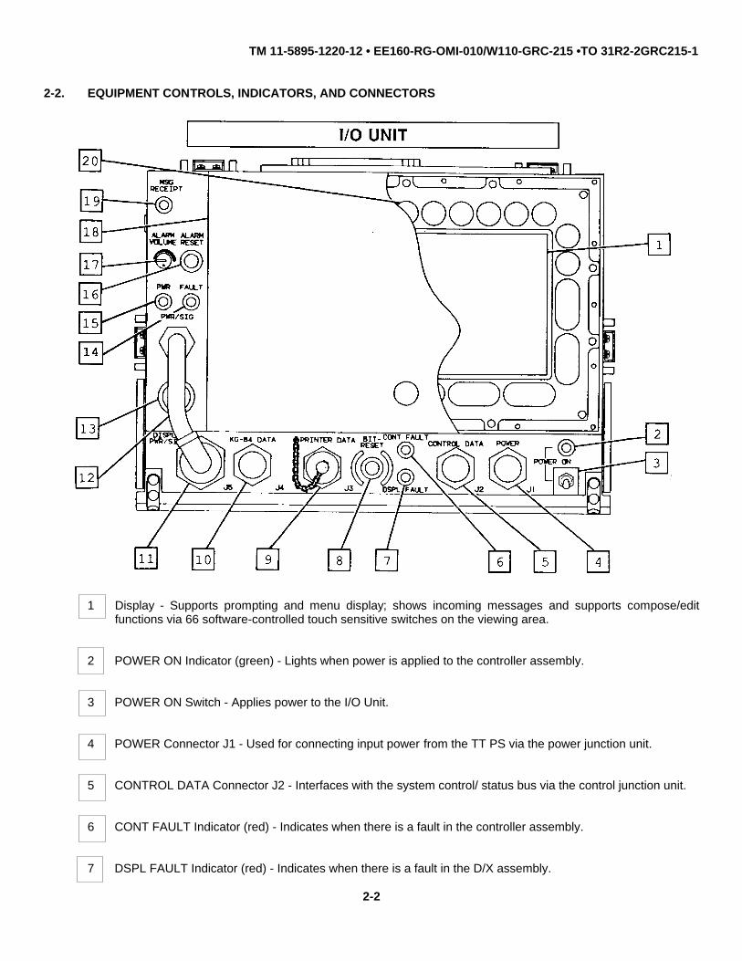
2-2. EQUIPMENT CONTROLS, INDICATORS, AND CONNECTORS
1 Display - Supports prompting and menu display; shows incoming messages and supports compose/editfunctions via 66 software-controlled touch sensitive switches on the viewing area.
2 POWER ON Indicator (green) - Lights when power is applied to the controller assembly.
3 POWER ON Switch - Applies power to the I/O Unit.
4 POWER Connector J1 - Used for connecting input power from the TT PS via the power junction unit.
5 CONTROL DATA Connector J2 - Interfaces with the system control/ status bus via the control junction unit.
6 CONT FAULT Indicator (red) - Indicates when there is a fault in the controller assembly.
7 DSPL FAULT Indicator (red) - Indicates when there is a fault in the D/X assembly.
2-2

TM 11-5895-1220-12 • EE160-RG-OMI-010/W110-GRC-215 •TO 31R2-2GRC215-1
2-2. EQUIPMENT CONTROLS, INDICATORS, AND CONNECTORS (Cont.)
I/O UNIT (Cont.)
NOTE
Operating parameters will need to be re-entered after pressing the BIT-RESET pushbutton switch.
8 BIT-RESET Pushbutton Switch - Initiates a reset of the I/O Unit similar to power on reset and performs off-line BIT of the I/O Unit (normally BIT should be performed by pressing the BIT bezel key). Operatingparameters will need to be re-entered after pressing the BIT-RESET pushbutton switch.
9 PRINTER DATA Connector J3 - Interfaces with printer (if optional printer is utilized).
10 KG-84 DATA Connector J4 - Signal interface for receive and transmit data timing and control.
11 DISPLAY PWR/SIG Connector J5 - Interfaces controller assembly with D/K assembly (whether D/K assemblyis mounted to the controller assembly or remoted).
12 PWR/SIG Cable - Power and signal interconnect cable from the D/K assembly.
13 Audible Alarm - The audible alarm indicates a message received or BIT fault.
14 FAULT Indicator (red) - Lights to indicate any fault detected in the Team Terminal.
15 PWR Indicator (green) - Lights when power is applied to the D/K assembly (especially useful when the D/Kassembly is remoted).
16 ALARM RESET Pushbutton Switch - Depressing this switch causes the audible alarm to be reset after it hasbeen activated.
17 ALARM VOLUME Control - Adjusts the volume of the audible alarm from maximum to minimum.
18 Display Cover - Provides protection for the display.
19 MSG RECEIPT Indicator (yellow) - Lights to indicate when a message has been received by the I/O Unit.
20 Bezel Keys - Used to control entry into major I/O functions, support editing operations, and provide generalutility functions.
2-3

TM 11-5895-1220-12 • EE160-RG-OMI-010/W110-GRC-215 •TO 31R2-2GRC215-1
2-2. EQUIPMENT CONTROLS, INDICATORS, AND CONNECTORS (Cont.)
I/O UNIT (Cont.)
BEZEL KEYS
MAINMENU Disposes of currently being edited parameters and displays the main menu.
XMT Used as the final approval key to transmit a message.
Saves the current menu being displayed, disposes of the currently being edited parameters, and initiates theSHOW show message procedure (para 2-7d). The show message mode allows the highest priority receivedMSG message in memory to be displayed. When the show message mode is exited the saved menu will be
displayed.
SET Saves the current menu being displayed, disposes of the currently being edited parameters, and initiates theUP operational set up procedure (para 2-7e). When the set up mode is exited, the saved menu will be displayed.
2-4

TM 11-5895-1220-12 • EE160-RG-OMI-010/W110-GRC-215 •TO 31R2-2GRC215-1
2-2. EQUIPMENT CONTROLS, INDICATORS, AND CONNECTORS (Cont.)
I/O UNIT (Cont.)
BEZEL KEYS (Cont.)
Initiates the terminal off-line BIT procedure (para 3-10a). Current operating parameters are retained.
Keys labeled with a • are not used.
Clears the status line on the display.
Clears all the data fields on the D/K assembly and displays the cursor at the initial field location.
Blanks the display and saves the current state of the display. Restores the display on any press of a bezelkey or touchpoint.
Places the compose/edit function in the insert mode until the INSRT bezel key is pressed again. Thisbezel key is only used on the compose/edit menu. The edited line has characters inserted at the cursorlocation. After a character insertion, the cursor and following text is shifted right one place. The lastcharacter is erased when shifted off the display.
Deletes the character at the current cursor position and left-justifies the line. The delete function is onlyused during compose/edit of messages. The delete function removes blank lines.
Scrolls the displayed message up four lines.
Scrolls the displayed message down four lines.
2-5

TM 11-5895-1220-12 • EE160-RG-OMI-010/W110-GRC-215 •TO 31R2-2GRC215-1
2-2. EQUIPMENT CONTROLS, INDICATORS, AND CONNECTORS (Cont.)
I/0 UNIT (Cont.)
BEZEL KEYS (Cont.)
Up arrow - Moves cursor up one line on the display during compose/edit function.
Down arrow - Moves cursor down one line on the display during compose/edit function.
Left arrow - Moves cursor left one character on the display with wrap to the next line duringcompose/edit function. When selecting parameters, moves cursor to next character inparameter field.
Right arrow - Moves cursor right one character on the display with wrap to the next line duringcompose/edit function. When selecting parameters, moves cursor to next character inparameter field.
2-6

TM 11-5895-1220-12 • EE160-RG-OMI-010/W110-GRC-215 •TO 31R2-2GRC215-1
2-2. EQUIPMENT CONTROLS, INDICATORS, AND CONNECTORS (Cont.)
I/O UNIT (Cont.)
BEZEL KEYS (Cont.)
When selecting parameters, this double bezel key terminates a field entry andcauses the cursor to move to the next field if the current field parameter is valid.When in compose/edit function, this bezel key moves to next line of text or opensa line if insert mode is enabled. Both enter positions are active and provideredundant operation.
Saves the entered parameters, exits from the current menu and displays the next menu insequence.
The current edit parameters are disposed of and the previous menu in the sequence is displayed.May be used to step back through previously displayed menus.
Places the Team Terminal in data mode and starts the data mode menu sequence.
Places the Team Terminal in voice mode and starts the voice mode menu sequence.
This is a select function to either enable or disable receive/transmit messages on the printer (ifprinter is available). The print selection enable or disable is displayed on the display status line.This entry has no effect on previous menu operations.
Initiates the zeroize procedure (para 2-7h) and terminates menu editing procedures.
Causes the current menu to be exited, disposing of the currently being edited parameters, andgoing to the start of the current menu sequence.
Initiates the leave net procedure (para 2-7g) and terminates menu editing procedures.
2-7

TM 11-5895-1220-12 • EE160-RG-OMI-010/W110-GRC-215 •TO 31R2-2GRC215-1
2-2. EQUIPMENT CONTROLS, INDICATORS, AND CONNECTORS (Cont.)
VEHICULAR ADAPTER
2-8

TM 11-5895-1220-12 • EE160-RG-OMI-010/W110-GRC-215 •TO 31R2-2GRC215-1
2-2. EQUIPMENT CONTROLS, INDICATORS, AND CONNECTORS (Cont.)
VEHICULAR ADAPTER (Cont.)
1 Connector P3 - Interfaces R/E with Vehicular Adapter.
2 10 MHz IN Connector - Interfaces with external frequency reference (RFO output).
3 FAST SYNTH Connector - Interfaces the ECCM Module with the high speed synthesizer contained in theVehicular Adapter.
4 FAULT Indicator (red) - When lighted, indicates a failure in the high speed synthesizer.
5 POWER SUPPLY Connector - Used to connect input power from the TT PS via the power junction unit (+8.5Vdc and +28.0 Vdc).
6 Fuse F1 - 5 A fuse for over-current condition in the +8.5 Vdc power supply contained in the VehicularAdapter.
7 Fuse F2 - 4 A fuse for over-current condition in the +24 Vdc power supply contained in the Vehicular Adapter.
8 Power Supply ON Indicator (green) - When lighted, indicates presence of both feeding voltages (+8.5 Vdcand +28 Vdc).
9 RCS - BAT CHG Indicator (green) - When lighted, indicates charge in process for Remote Control Set (RCS)battery.
10 MP - BAT CHG Indicator (green) - When lighted, indicates charge in process for Manpack (MP) BatteryCase/Charger battery.
11 PA/ATU Connector - Interfaces PA and ATU with the Vehicular Adapter.
12 Connector P1 - Interfaces Battery Case/Charger with the Vehicular Adapter.
13 Compartment for battery charger feeder cable.
14 Battery Charger Feeder Cable - Used for charging Remote Control Set battery.
15 GRD (Ground) Post - Used for connecting ground strap.
16 Fan - Goes on automatically when the temperature exceeds 700C and the RT is in the transmit mode.
2-9

TM 11-5895-1220-12 • EE160-RG-OMI-010/W110-GRC-215 •TO 31R2-2GRC215-1
2-2. EQUIPMENT CONTROLS, INDICATORS, AND CONNECTORS (Cont.)
RT
The RT includes the following:
• R/E
• ECCM Module.
R/E
2-10

TM 11-5895-1220-12 • EE160-RG-OMI-010/W110-GRC-215 •TO 31R2-2GRC215-1
2-2. EQUIPMENT CONTROLS, INDICATORS, AND CONNECTORS (Cont.)
RT (Cont.)
R/E (Cont.)
1 DIP 50 Connector - Interfaces with RF signal cable from PA when in vehicular configuration.
2 Connector J1 - Interfaces R/E with ECCM Module (or Remote Control Set R/E terminal when ECCM Moduleis remoted).
3 GRD Post - Not used.
4 Antenna Connector - Interfaces with Manpack Whip Antenna.
5 Power ON-OFF Switch - Applies power to the RT (and the PA, ATU, and Vehicular Adapter when in vehicularconfiguration).
6 Connector J2 - Interfaces with Vehicular Adapter (or Battery Case/Charger when in Manpack configuration).
2-11

TM 11-5895-1220-12 • EE160-RG-OMI-010/W110-GRC-215 •TO 31R2-2GRC215-1
2-2. EQUIPMENT CONTROLS, INDICATORS, AND CONNECTORS (Cont.)
RT (Cont.)
ECCM MODULE (Cont).
The one key provides numeric entry for frequency data. When coupled with the 2ND function key,activates the load TRANSEC variable mode.
The two key provides numeric entry for frequency data. When coupled with the 2ND function key,allows the frequency to be increased by 10 Hz each time it is pressed. If the key is helddepressed, the unit will continually increase the frequency at a one change per second rate.
The three key provides numeric entry for frequency data. When coupled with the 2ND functionkey, allows the frequency to be decreased by 10 Hz each time it is pressed. If the key is helddepressed, the unit will continually decrease the frequency at a one change per second rate.
2-12

TM 11-5895-1220-12 • EE160-RG-OMI-010/W110-GRC-215 •TO 31R2-2GRC215-1
2-2. EQUIPMENT CONTROLS, INDICATORS, AND CONNECTORS (Cont.)
RT (Cont.)
ECCM MODULE (Cont.)
The four key provides numeric entry for frequency data. When coupled with 2ND function key,changes the power level (low (5W), medium (25W), or high (100W)).
The five key provides numeric entry for frequency data. When coupled with the 2ND function key,activates the voice ECCM mode.
The six key provides numeric entry for frequency data. When coupled with the 2ND function key,will change sidebands from upper sideband to lower sideband or from lower sideband to uppersideband.
The seven key provides numeric entry for frequency data. When coupled with the 2ND functionkey, it erases the previous keystroke.
The eight key provides numeric entry for frequency data.The TOD function key is not used.
The nine key provides numeric entry for frequency data. When coupled with the 2ND functionkey, provides a continuous tone in transmit.
The second function key activates the alternate mode for each of the other keys.
The zero key provides numeric entry for frequency data. When coupled with the 2ND functionkey, activates the preset mode. This includes both loading and recalling presets.
The enter key completes each change initiated by another key or series of keys. When coupledwith 2ND function key, it initiates the RT off-line BIT function.
2-13

TM 11-5895-1220-12 • EE160-RG-OMI-010/W110-GRC-215 •TO 31R2-2GRC215-1
2-2. EQUIPMENT CONTROLS, INDICATORS, AND CONNECTORS (Cont.)
RT (Cont.)
ECCM MODULE (Cont.)
2 3
2 FILL Connector J5 - Interfaces with fill device for loading variables into the ECCM Module.
3 ZERO Switch - Depressing this switch, zeroizes all variables in the ECCM Module.
4 REMOTE Connector J6 - Provides interface connections to the RN Modem and the I/O Unit.
5 BTRY INSTLD - This is space for writing the date when a battery was last installed in the compartmentbehind front panel of ECCM Module. Battery provides for non-destructive storage of variables and presetswhen equipment is powered-off.
6 SYNC Connector J4 - Provides audio signals and synchronized PTT keying from the RT to TSEC/KY-65.
7 KY Connector J3 - When operating in secure voice mode, the Handset is connected to this connector. Itobtains PTT keying for processing and routes audio signals to the SYNC connector J4.
2-14

TM 11-5895-1220-12 • EE160-RG-OMI-010/W110-GRC-215 •TO 31R2-2GRC215-1
2-2. EQUIPMENT CONTROLS, INDICATORS, AND CONNECTORS (Cont.)
RT (Cont.)
ECCM MODULE (Cont.)
8 Display - Shows RT frequency setting, operating modes, and fault codes.
• LPR - Indicates low power transmit mode.
• MPR - Indicates medium power transmit mode.
• HPR - Indicates high power transmit mode.
• LSB - Indicates lower sideband operating mode.
• USB - Indicates upper sideband operating mode.
• TUN - Indicates fine tune mode has been initiated.
• Ñ - Indicates increase operating frequency mode has been initiated.
• Ò - Indicates decrease operating frequency mode has been initiated.
• VAR - Indicates load variables mode has been initiated.
• CTN - Indicates continuous tone mode has been initiated.
• FAIL- Indicates the unit's BIT has detected a fault.
9 VOL Control - Adjusts the receive audio level in the Handset (when not using the TSEC/KY-65).
10 VEH ADPTR Connector J2 - Provides interface from ECCM Module to the Vehicular Adapter to gain highspeed synthesizer capabilities.
11 AUDIO Connector J1 - Interfaces with audio signals from TSEC/KY-65 or Handset.
12 Connector P1 - Interfaces with R/E (or remote location when ECCM Module is remoted).
13 Connector P2 - Not used in Team Terminal application.
2-15
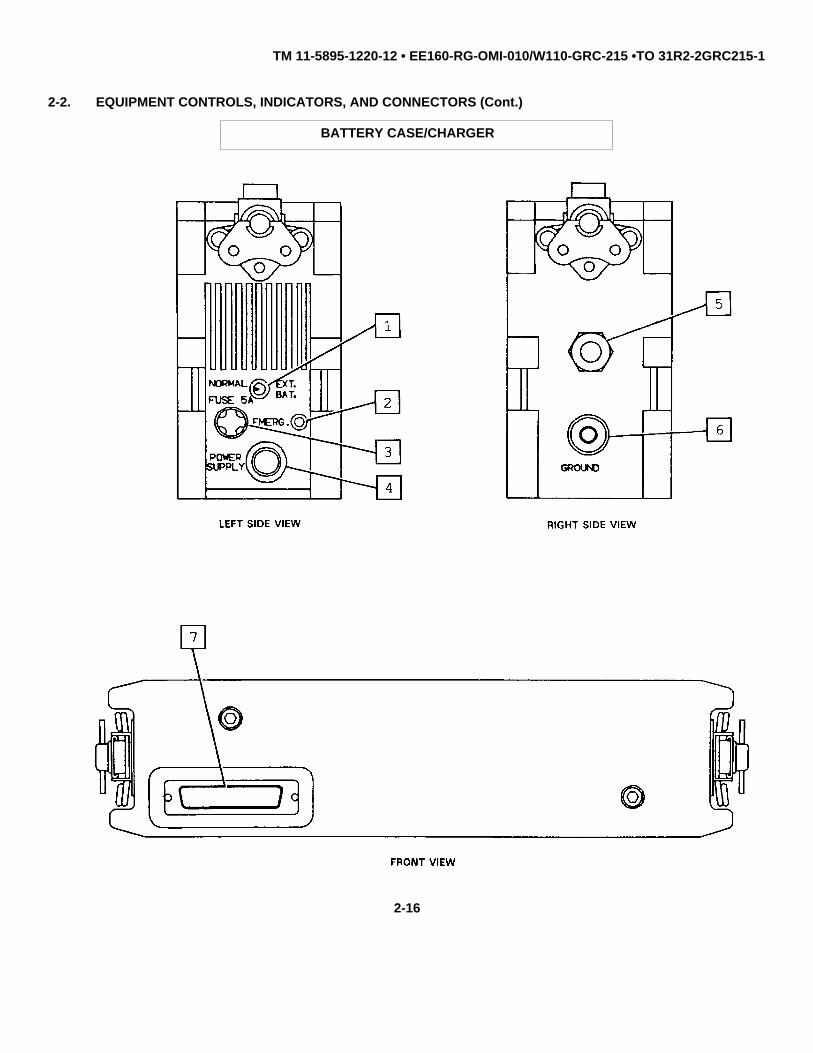
TM 11-5895-1220-12 • EE160-RG-OMI-010/W110-GRC-215 •TO 31R2-2GRC215-1
2-2. EQUIPMENT CONTROLS, INDICATORS, AND CONNECTORS (Cont.)
BATTERY CASE/CHARGER
2-16

TM 11-5895-1220-12 • EE160-RG-OMI-010/W110-GRC-215 •TO 31R2-2GRC215-1
2-2. EQUIPMENT CONTROLS, INDICATORS, AND CONNECTORS (Cont.)
BATTERY CASE/CHARGER (Cont.)
1 NORMAL-EXT. BAT. Switch
• NORMAL - Allows recharge of batteries when Battery Case/ Charger is mounted to Vehicular Adapter.Enables batteries to power the RT when in Manpack configuration.
• EXT. BAT. - Allows an external power supply (+24 Vdc) to power the Manpack via POWER SUPPLYconnector 4
2 EMERG. Indicator (green) - Lights to indicate battery charge in process.
3 FUSE 5A - Protects against an over-current condition.
4 POWER SUPPLY Connector - Interfaces with external power supply, hand-generator, or solar cells.
5 Relief Valve - Provides battery case venting to preclude an internal pressure build-up.
6 GROUND Post - Not used.
7 Connector J2 - Interfaces with Vehicular Adapter when in vehicular configuration or R/E when in Manpackconfiguration.
2-17

TM 11-5895-1220-12 • EE160-RG-OMI-010/W110-GRC-215 •TO 31R2-2GRC215-1
2-2. EQUIPMENT CONTROLS, INDICATORS, AND CONNECTORS (Cont.)
PA
1 Power ON Indicator (green) - Lights when power is applied to the PA.
2 VSWR Indicator (yellow) - Lights to indicate a VSWR that exceeds 3:1 (i.e. antenna mismatch).
3 FAIL Indicator (red) - Lights to indicate a faulty PA.
4 Connector J1 - Provides connections for input power from TT PS via the power junction unit.
5 Ground Post - Connects external ground strap.
6 Connector J3 (TNC type) - Provides connection for RF input from the R/E.
7 Connector J2 - Provides connection for control signals from Vehicular Adapter.
8 Connector J4 (N type) - Provides connection for RF output to the ATU.
2-18

TM 11-5895-1220-12 • EE160-RG-OMI-010/W110-GRC-215 •TO 31R2-2GRC215-1
2-2. EQUIPMENT CONTROLS, INDICATORS, AND CONNECTORS (Cont.)
ATU
1 Connector J2 - Provides connection for RF signal from the PA.
2 Connector J1 - Provides connection for control signals from the Vehicular Adapter.
3 Ground Post - Connects external ground strap.
4 Connector J3 - Provides connection for input power from TT PS via power junction unit.
5 Antenna Matching Capacitor - Provides additional capacitance for when ATU is tuning to NVIS Antenna. Alsoprovides for connection between ATU and antenna cable W1.
6 Antenna Insulator E1 - Provides for RF output from the ATU. Also provides for the indirect (through antennamatching capacitor) HF antenna connection.
7 ATU Safety Cap - A cone shaped nylon insulator covering the ATU Antenna insulator and matchingcapacitor.
Change 2 2-19

TM 11-5895-1220-12 • EE160-RG-OMI-010/W110-GRC-215 •TO 31R2-2GRC215-1
2-2. EQUIPMENT CONTROLS, INDICATORS, AND CONNECTORS (Cont.)
TT PS
2-20

TM 11-5895-1220-12 • EE160-RG-OMI-010/W110-GRC-215 •TO 31R2-2GRC215-1
2-2. EQUIPMENT CONTROLS, INDICATORS, AND CONNECTORS (Cont.)
TT PS (Cont.)
1 FAULT Indicator (red) - Lights to indicate a fault in TT PS.
2 RFO ON-OFF Switch - When using a +24 Vdc power source, this switch when left set to ON, applies keep-alive voltage (+24 Vdc) to the RFO for TOD retention, even if both AC and DC ON-OFF switches on the TTPS are set to OFF.
3 PWR IN Connector J1 - Interfaces with Vehicle Input Power Cable or 115/230 Vac Input Power Cable.
4 OUTPUT VOLTAGE Meter - Provides voltage reading for +28 Vdc output.
5 DC ON-OFF Switch - When dc power is used as the input source, this switch is used to apply power to theTT PS.
6 AC ON-OFF Switch - When ac power is used as the input source, this switch is used to apply power to theTT PS.
7 POWER Indicator (green) - Lights to indicate TT PS is supplying output power (+28 Vdc).
8 Connector P1 - Interfaces +28 Vdc and +8.5 Vdc power output from the TT PS with the power junction unit.
2-21

TM 11-5895-1220-12 • EE160-RG-OMI-010/W110-GRC-215 •TO 31R2-2GRC215-1
2-2. EQUIPMENT CONTROLS, INDICATORS, AND CONNECTORS (Cont.)
RFO
1 BATTERY STATUS Indicator (green) - Lights when the BATTERY TEST switch is pressed if battery hassufficient charge. Failure of the indicator to light during tests indicates that batteries need charging orreplacing.
2 RCV TOD Switch - Used to receive time-of-day (TOD) from a TOD source. Pressing switch enables the RFOto accept a TOD signal.
3 SET CLOCK Indicator (red) - Indicates that the oscillator does not contain a TOD. The indicator lights forapproximately two seconds upon power-up.
2-22

TM 11-5895-1220-12 • EE160-RG-OMI-010/W110-GRC-215 •TO 31R2-2GRC215-1
2-2. EQUIPMENT CONTROLS, INDICATORS, AND CONNECTORS (Cont.)
RFO (Cont.)
4 COLD OSC Indicator (red) - Lights when the internal oscillator is cold (not stabilized); usually at initial turn-on.The indicator will go out when warm-up period is over.
5 FAULT Indicator (red) - Lights when RFO output is not within limits.
6 LAMPS - Turns indicator lamps OFF and permits adjusting lamp intensity (BRIGHT-DIM).
7 EXT POWER Indicator (green) - Lights when power is applied to the RFO.
8 RESET-OFF Switch - Provides power on-off control to the RFO. The switch is protected against accidentaloperation by a hinged protective cover. TOD is lost when this switch is put in the OFF position. When switchis in RESET position and you disconnect the power, the keep-alive battery in the RFO will retain TOD.
9 +27 VDC POWER Connector - Provides connections for input power from the TT PS.
10 SYSTEM INTERFACE Connector - Interfaces RFO with system through control junction unit.
11 10 MHZ OUT Connector - Used to supply a 10 MHz reference signal.
12 SEND TOD Switch - Pressing the switch sends TOD data to another RFO.
13 TIME TRANSFER Connector - Enables TOD to be sent to or received from another RFO. A TOD transfercable is used to provide the connection to another RFO, RN FT, or FAN FT.
14 R-2171 Input Connector - Used to input satellite time from a Satellite Action Logic Transfer (SALT) box.
15 BATT TEST Switch - Press-to-test switch to determine internal battery condition. Used with BATTERYSTATUS indicator.
Change 1 2-23

TM 11-5895-1220-12 • EE160-RG-OMI-010/W110-GRC-215 •TO 31R2-2GRC215-1
2-2. EQUIPMENT CONTROLS, INDICATORS, AND CONNECTORS (Cont.)
RN MODEM
1 RADIO Connector J1 - Provides interface between the ECCM Module and the RN Modem.
2 FREQ STAND Connector J2 - Provides 10 MHz frequency reference to RN Modem from the RFO.
2-24

TM 11-5895-1220-12 • EE160-RG-OMI-010/W110-GRC-215 •TO 31R2-2GRC215-1
2-2. EQUIPMENT CONTROLS, INDICATORS, AND CONNECTORS (Cont.)
RN MODEM (Cont.)
3 CONTROL BUS Connector J3 - Serial bus that provides control information from the I/O Unit and allowsstatus information to be returned to the I/O Unit.
4 BIT Fault Indicator (red) - Indicator that provides status on the results of BIT. Indicator is continuously lightedduring a fault, flashes during performance of off-line BIT and is off in the absence of faults. This indicator willalso light to indicate crypto-alarm state in the TSEC/KG-84A.
5 BIT Initiate Switch - Initiates off-line BIT.
6 PWR ON Indicator (green) - Lights when power is applied to RN Modem.
7 PWR ON-OFF Switch - Applies power to the RN Modem.
8 PWR IN Connector J5 - Provides connection for input power from TT PS via power junction unit.
9 KG-84 Connector J4 - Provides black data interface between TSEC/KG-84A and RN Modem.
2-25

TM 11-5895-1220-12 • EE160-RG-OMI-010/W110-GRC-215 •TO 31R2-2GRC215-1
2-2. EQUIPMENT CONTROLS, INDICATORS, AND CONNECTORS (Cont.)
REMOTE CONTROL SET
• The Remote Control Set includes the following:
• Remote Location
R/E Terminal
REMOTE LOCATION
2-26

TM 11-5895-1220-12 • EE160-RG-OMI-010/W110-GRC-215 •TO 31R2-2GRC215-1
2-2. EQUIPMENT CONTROLS, INDICATORS, AND CONNECTORS (Cont.)
REMOTE CONTROL SET (Cont.)
REMOTE LOCATION (Cont.)
1 PWR SUP. Connector - Interfaces the remote location with an external power source or for recharge ofbattery when connected to the Vehicular Adapter.
2 BAT. CHG Indicator - Lights to indicate battery charge in process.
3 CALL Switch - Pushbutton for the call signal of the local operator.
4 R/T-OFF-TEL Switch - 3 Position Switch, selects operating condition R/T or Telephone or OFF.
5 GRD Post - Used for ground connection of Remote Control Set.
6 Carrying Belt.
7 Binding Posts - Used for the connection of the two terminal units (remote location and R/E terminal) throughtelephone field wire.
8 Breather Valve - Used for the exit of gas produced by batteries.
9 Connector J3 - Interface connector between remote location and the ECCM Module when in remoteconfiguration (interfaces with R/E terminal when R/E terminal is recovered from the R/E).
2-27

TM 11-5895-1220-12 • EE160-RG-OMI-010/W110-GRC-215 •TO 31R2-2GRC215-1
2-2. EQUIPMENT CONTROLS, INDICATORS, AND CONNECTORS (Cont.)
REMOTE CONTROL SET (Cont.)
R/E TERMINAL
2-28

M 11-5895-1220-12 • EE160-RG-OMI-010/W110-GRC-215 • TO 31R2-2GRC215-1
2-2. EQUIPMENT CONTROLS, INDICATORS, AND CONNECTORS (Cont.)
REMOTE CONTROL SET (Cont.)
R/E TERMINAL (Cont.)
1. BITE Indicator (red) - Lights to indicate a failure in the R/E.
2. LINE Binding Posts - Used for the connection of the two terminal units (R/E terminal and remote location)through telephone field wire.
3. AUDIO Connector - Allows the operations of transmission and reception in the R/E terminal whenHeadset/Handset is connected.
4. GRD Post - Connects to ground strap.
5. R/T-TEL. Switch - Used to select operating condition: receive/transmit or telephone.
6. VOLUME Control - Adjustment for Handset/Headset volume.
7. CALL Switch - Pushbutton for signal call generation.
8. Connector - Interface connector between R/E terminal and R/E when in remote configuration (interfaces withremote location when R/E terminal is recovered from a remote deployment).
2-29
TM 11-5895-1220-12 • EE160-RG-OMI-010/W110-GRC-215 • TO 31R2-2GRC215-1
Section II. OPERATOR PREVENTIVE MAINTENANCE CHECKSAND SERVICES (PMCS)
2-3. GENERAL
NOTE
When performing PMCS or routine checks, observe all WARNINGS andCAUTIONS listed at the beginning of this manual, at the appropriateplace in the procedures, or on plates and decals attached to theequipment.
Operator preventive maintenance is the systematic care, servicing, and inspection of equipment to prevent the occurrenceof failure, to reduce downtime, and to maintain equipment in serviceable condition. To be sure that the equipment isalways ready for a mission, do the schedule PMCS.
a. Maintenance Forms and Records. The forms and records you fill out have several uses, including: (1) apermanent record of the services, repairs and modifications made to your equipment; (2) reports to the next level ofmaintenance and to your commander; and (3) a checklist for you when you want to know the status of the equipment afterits last use, and whether faults, if any, have been fixed. For information on forms and records, see DA Pam 738-750.
b. Routine Checks. Routine checks such as cleaning, dusting, and washing, stowing items not in use, coveringunused receptacles, and checking for damage, are not listed on PMCS checks. They are things you should do any timeyou see they must be done. Ensure that all discrepancies are noted and corrected.
c. Operator PMCS. Operator’s PMCS are the required periodic inspections and actions necessary to keep yourequipment in good operating condition. PMCS should be performed if/when:
(1) You are the assigned operator and have not operated the Terminal since the last PMCS.
(2) You are operating the equipment for the first time.
(3) Whenever a component is removed or installed for any reason.
d. PMCS PROCEDURES.
(1) Continuous Operation. If equipment must be kept in continuous operation, check and service those itemsthat can be done without disturbing operation. Make the complete checks and services when the equipment is not in use.
(2) Scheduling. PMCS must be done at the specified times if possible. If operational requirements preventdoing PMCS at the specified time, make the required checks and services at the first opportunity.
Change 1 2-30

TM 11-5895-1220-12 • EE160-RG-OMI-010/W110-GRC-215 • TO 31R2-2GRC215-1
2-4. OPERATOR PMCS TABLE
The PMCS table lists all the scheduled maintenance tasks required for your system.
a. Explanation of Columns.
(1) Item No. This column contains a number for each procedure to be performed. When reportingmalfunctions or failures on DA Form 2404, Equipment Inspection and Maintenance Worksheet, place this number in the"TM Item No." column.
(2) Interval. These columns tell you when to do a procedure. Each column that applies will contain a bullet (•). Some procedures will have bullets in more than one column.
(3) Item to be inspected/procedure. This column contains the name of the item to be inspected and tells howto perform the required checks and services on it. Carefully follow these instructions and perform them in the order listed.
(4) Equipment is not ready/available if:. This column tells you the conditions which will cause the equipmentto be classified as not ready for readiness reporting.
b. Instructions.
(1) Do your before (B) preventive maintenance just before you operate your equipment. Pay attention toCAUTIONS and WARNINGS.
(2) Do your during (D) preventive maintenance while the equipment and/or its components systems are inoperation.
(3) Do your after (A) preventive maintenance right after operating the equipment. Pay attention toCAUTIONS and WARNINGS.
(4) If a malfunction should occur, refer to the MAC at appendix B to determine at what level corrective actionshould occur. Take appropriate corrective action and report all uncorrected faults to your supervisor IMMEDIATELY.
(5) Always do your preventive maintenance in the same order.
(6) If anything goes wrong and you can't fix it, write on your DA Form 2404, or other applicable form. If youfind something seriously wrong, report it to the next level of maintenance IMMEDIATELY.
Change 1 2-31

TM 11-5895-1220-12 • EE160-RG-OMI-010/W110-GRC-215 • TO 31R2-2GRC215-1
WARNING
• Never operate the equipment until it has been properly grounded.Electrical defects in the load lines or equipment can cause DEATH byelectrocution when contact is made with an ungrounded system.
• Compressed air shall not be used for cleaning purposes except wherereduced to less than 29 psi and then only with effective chip guardingand personnel protective equipment. Compressed air is dangerousand can cause serious bodily harm if protective means or methods arenot observed to prevent chips or particles (of whatever size) frombeing blown into the eyes or unbroken skin of the operator or otherpersonnel.
NOTE
Your equipment may still be rated mission capable with component(s)rated not ready if that/these component(s) are not required to support theassigned mission.
OPERATOR PMCS TABLE
Operator Preventive Maintenance Checks and Services
Item Interval Item to be Inspected Equipment is notNo. B D A Procedure ready/available if:1 • • Whip Antenna
Check that antenna is securely Antenna broken or notmounted and not broken. Check that securely mounted.cable is firmly mated with antenna Cable not securelyconnection. Ensure antenna tip-cap is mated to the antennainstalled. connector. Antenna
tip-cap is missing.
2 • • Rack Assembly and Shock mountsCheck that rack assembly and shock Damage to the equip-mounts are secure and have not be- ment that presents acome displaced during transportation. hazard or a conditionCheck that attaching hardware is not that can cause damagemissing. to equipment.
Change 1 2-32

TM 11-5895-1220-12 • EE160-RG-OMI-010/W110-GRC-215 • TO 31R2-2GRC215-1
2-4. OPERATOR PMCS TABLE (Cont.)
Operator Preventive Maintenance Checks and Services
Item Interval Item to be Inspected Equipment is notNo. B D A Procedure ready/available if:3 • Cables
Check for frayed or broken cables. Cables are frayed orCheck that cables are securely con- broken; improperlynected to the correct connector; see installed.equipment hook-up chart (para 4-7a)
4 • GroundsAll ground straps must be secure. If Ground straps loose oroperating at halt and operating from a not installed. Motormotor generator, power ground must generator notbe installed. grounded.
5 • • HandsetCheck that the handset mates are with Handset is defectivethe appropriate connector. and no replacement isavailable.
6 • Communication Equipment includingData/Voice checkDuring operation, daily, weekly if not; Fault or fail indicatorscheck of all fault and performance in- light, or Terminal off-dicators includes terminal off-line Bit line Bit fails. Com-(para 3-10). Check that communica- munications with dis-tions with a distant station may be ac- tant station is not pos-complished in a satisfactory manner sible.
Change 1 2-33

TM 11-5895-1220-12 • EE160-RG-OMI-010/W110-GRC-215 • TO 31R2-2GRC215-1
Section III. OPERATION UNDER USUAL CONDITIONS
2-5. ASSEMBLY AND PREPARATION FOR USE
Following are procedures for assembly and preparation for use of the Team Terminal in the vehicular configurationand in the manpack configuration. In addition to these procedures, Battery BA-1372/U (user-supplied) must be installed inthe ECCM Module (contact MMCT).
a. Vehicular Configuration. Assembly and preparation for use for vehicular operations include the followingprocedures:
• Installation of COMSEC equipment (The Team Terminal is shipped without COMSEC equipment. ATSEC/KY-65A and a TSEC/KG-84A are required).
• KG-84A nonsecure bypass assembly hookup (required only when in nonsecure data operations).
•· Configure for Remote Data/Voice Operation (as desired).
• Installation of Whip or NVIS Antenna.
• Vehicle grounding. When operating at halt, ground the vehicle. The angle washer located on the antennabase provides a convenient location to attach a ground strap.
(1) Installation of TSEC/KY-65A. Preparation for and installation of the TSEC/KY-65A must be made with theassistance of unit or higher level maintenance.
INSTALLATION OF TSEC/KY-65A
STEP1 Ensure TT PS DC and AC ON-OFFswitches are set to OFF. If TSEC/KY-65Ais not configured with Z-AKE, installZ-AKE on rear of TSEC/KY-65A and fasten
STEP2 Refer to TM 11-5810-280-12 & Pand perform assembly and preparationfor use procedures for the TSEC/KY-65A.
Change 1 2-34

TM 11-5895-1220-12 • EE160-RG-OMI-010/W110-GRC-215 • TO 31R2-2GRC215-1
2-5. ASSEMBLY AND PREPARATION FOR USE (Cont.)
(2) Configure Manpack for Secure Voice Operation
INSTALLATION OF TSEC/KY-65A (cont.)
STEP3 Slide TSEC/KY-65A to itsstationary position in rack andconnect cable plug W108P1 to POWERconnector J1 on Z-AKE rear panel.
STEP4 Align 2 thumbscrew clampsinto position and tighten tosecure TSEC/KY-65A to its mount.
STEP5 On TSEC/KY-65A front panelmake the following connections:
TSEC/KY-65ACable/plug connector
W307P2 HANDSET connectorW308P2 RADIO connectorGround strap Ground terminal
2-35

TM 11-5895-1220-12 • EE160-RG-OMI-010/W110-GRC-215 • TO 31R2-2GRC215-1
2-5. ASSEMBLY AND PREPARATION FOR USE (Cont.)
(2) Installation of TSEC/KG-84A. Preparation of the TSEC/KG-84A must be made with the assistance of unit orhigher level maintenance.
INSTALLATION OF TSEC/KG-84A
STEP1 Ensure TT PS DC and AC ON-OFFswitches are set to OFF. Disconnectcable plugs W306P1, W103P1, andW305P2 from J2, J1, and J3 on KG-84Anonsecure BYPASS ASSEMBLY. Placeconnector covers on connectors J2and J3.
STEP2 Check battery installation datewritten on front panel of TSEC/KG-84A.Replace battery when more than 90 daysold. Notify MMCT.
2-36

TM 11-5895-1220-12 • EE160-RG-OMI-010/W110-GRC-215 • TO 31R2-2GRC215-1
2-5. ASSEMBLY AND PREPARATION FOR USE (Cont.)
INSTALLATION OF TSEC/KG-84A
STEP3 Compare KG-84 STRAPPING CHART with chart on right-hand side of TSEC/KG-84A. Ensure correct strapping isinstalled. Installed straps are indicated with a check mark in box on chart. If strapping is incorrect notify MMCT.
KG-84 STRAPPING CHART
BD - PLUG FUNCTION STRAPPING
P2 ETCT [ ] BAL: J6-J7 [X] UNBAL: J5-J6P3 J8-J9 J9-J10
A1 P4 XMT CTRL/CTTR [ ] BAL: J12-J13 [X] UNBAL: Jll-J12P5 J15-J16 J14-J15
P6 INTERFACE [X] KG-84A: J17A [ ] KG-84: J17B
P2 TCTC [ ] BAL J6-J7 [X] UNBAL J5-J7P3 J9-J10 J8-J10
A2 P4 CLK LOCK [ ] DSBL: J20-J22 [X] ENBL: J21-J22
P5 CTCD/CTRS [ ] BAL J15-J16 [X] UNBAL J14-J16P7 J12-J13 J11-J13
P6 CTCD/CTRS [X] KG-84A J18-J19 [ ] KG-84: J17-J18
P2 TIME OUT [ ] DSBL: J8-J9 [X] ENBL: J9-J10
A5 P3 VUX [ ] DSBL: J5-J7 [X] ENBL: J5-J6
P4 FILL SELECT [X] KG-84A: Jll-J12 [ ] KG-84: J12-J13
A6 P2 U UPDATE [X] ENBL: J7-J8 [ ] DSBL: J8-J9
P2 RED I/O [ ] BAL: J14 [X] UNBAL: J6P3 J15 J7
A9 P4 STEP PULSE [ ] SGL: J8-J9 [X] DBL: J9-J10
P5 TX CLOCK [X] CONT: J11-J12 [ ] GATED: J12-J13
2-37
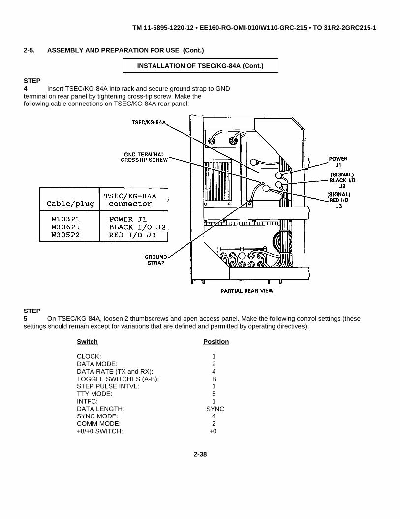
TM 11-5895-1220-12 • EE160-RG-OMI-010/W110-GRC-215 • TO 31R2-2GRC215-1
2-5. ASSEMBLY AND PREPARATION FOR USE (Cont.)
INSTALLATION OF TSEC/KG-84A (Cont.)
STEP4 Insert TSEC/KG-84A into rack and secure ground strap to GNDterminal on rear panel by tightening cross-tip screw. Make thefollowing cable connections on TSEC/KG-84A rear panel:
STEP5 On TSEC/KG-84A, loosen 2 thumbscrews and open access panel. Make the following control settings (thesesettings should remain except for variations that are defined and permitted by operating directives):
Switch Position
CLOCK: 1DATA MODE: 2DATA RATE (TX and RX): 4TOGGLE SWITCHES (A-B): BSTEP PULSE INTVL: 1TTY MODE: 5INTFC: 1DATA LENGTH: SYNCSYNC MODE: 4COMM MODE: 2+8/+0 SWITCH: +0
2-38

TM 11-5895-1220-12 • EE160-RG-OMI-010/W110-GRC-215 • TO 31R2-2GRC215-1
2-5. ASSEMBLY AND PREPARATION FOR USE (Cont.)
INSTALLATION OF TSEC/KG-84A
STEP6 Slide TSEC/KG-84A to its stationary position on its mount and secure by tightening 2 clamp bolt assemblies asfollows:
• Slide collars onto hold down hooks on TSEC/KG-84A.
• Tighten knobs.
2-39

TM 11-5895-1220-12 • EE160-RG-OMI-010/W110-GRC-215 • TO 31R2-2GRC215-1
2-5. ASSEMBLY AND PREPARATION FOR USE (Cont.)
(3) KG-84 Nonsecure Bypass Assembly Hookup. The KG-84 nonsecure bypass assembly is utilized duringnonsecure data operations (with TSEC/KG-84A removed).
KG-84A NONSECURE BYPASS ASSEMBLY HOOKUP
STEP1 On TSEC/KG-84A, pull out andset ENABLE-ZEROIZE switch toZEROIZEposition and set POWER ON-OFF switchto OFF. Ensure TT PS DC and ACON-OFF switches are set to OFF (IfTeam Terminal is powered up, performpower-off sequence (para 2-7i).
STEP2 Loosen 2 clamp bolt assembliesto free TSEC/KG-84A from its mount.
• Loosen knobs.
• Slide collars offof hold down hooksand allow clamp boltassembly to fall freeof TSEC/KG-84A.
STEP3 On rear panel of TSEC/KG-84A,disconnect cable plugs W103P1,W306P1, and W305P2 and then dis-connect ground strap.
2-40

TM 11-5895-1220-12 • EE160-RG-OMI-010/W110-GRC-215 • TO 31R2-2GRC215-1
2-5. ASSEMBLY AND PREPARATION FOR USE (Cont.)
KG-84A NONSECURE BYPASS ASSEMBLY HOOKUP (Cont.)
STEP4 Remove TSEC/KG-84A from its mount.
STEP5 Remove connector coversfrom connectors J3 and J2 onKG-84 nonsecure BYPASS ASSEMBLY.
STEP6 Make the following connectionsto KG-84 nonsecure bypass assembly:
KG-84 nonsecurebypass assembly
Cable/plug connector
W103P1 J1W306P1 J2W305P2 J3
2-41

TM 11-5895-1220-12 • EE160-RG-OMI-010/W110-GRC-215 • TO 31R2-2GRC215-1
2-5. ASSEMBLY AND PREPARATION FOR USE (Cont.)
(4) Configure for Remote Data Operation.
CONFIGURE FOR REMOTE DATA OPERATION
STEP1 On I/O Unit, set POWER ONswitch to off (down position).Disconnect cable plug W309P1 fromDISPLAY PWR/SIG connector J5.
STEP2 Loosen and free 4 springlatches (1 on each side, and 2on top). Remove the D/K assemblyfrom the I/O Unit.
STEP3 Interconnect the D/K assemblyand the controller assembly via remotecable W313 (20 ft) as follows:
Cable/plug Connector
W313P1 J5 on controller assemblyW313P2 W309P1 on remoted D/K
assembly
STEP4 Place the D/K assembly at desired remote location.
2-42

TM 11-5895-1220-12 • EE160-RG-OMI-010/W110-GRC-215 • TO 31R2-2GRC215-1
2-5. ASSEMBLY AND PREPARATION FOR USE (Cont.)
CONFIGURE FOR REMOTE DATA OPERATION (Cont.)
REPLACEMENT IN EQUIPMENT RACK
STEP1 On I/O Unit, set POWER ON switch to off (down) position.
STEP2 Disconnect remote cable W313 and place in storage area.
STEP3 Mount the D/K assembly on the controller assembly and secure byfastening 4 spring latches.
STEP4 Connect cable plug W309P1 to DISPLAY PWR/SIG connector J5 oncontroller assembly.
2-43
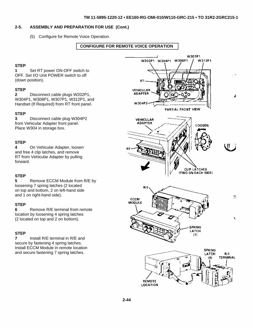
TM 11-5895-1220-12 • EE160-RG-OMI-010/W110-GRC-215 • TO 31R2-2GRC215-1
2-5. ASSEMBLY AND PREPARATION FOR USE (Cont.)
(5) Configure for Remote Voice Operation.
CONFIGURE FOR REMOTE VOICE OPERATION
STEP1 Set RT power ON-OFF switch toOFF. Set I/O Unit POWER switch to off(down position).
STEP2 Disconnect cable plugs W202P1,W304P1, W308P1, W307P1, W312P1, andHandset (If Required) from RT front panel.
STEP3 Disconnect cable plug W304P2from Vehicular Adapter front panel.Place W304 in storage box.
STEP4 On Vehicular Adapter, loosenand free 4 clip latches, and removeRT from Vehicular Adapter by pullingforward.
STEP5 Remove ECCM Module from R/E byloosening 7 spring latches (2 locatedon top and bottom, 2 on left-hand sideand 1 on right-hand side).
STEP6 Remove R/E terminal from remotelocation by loosening 4 spring latches(2 located on top and 2 on bottom).
STEP7 Install R/E terminal in R/E andsecure by fastening 4 spring latches.Install ECCM Module in remote locationand secure fastening 7 spring latches.
2-44

TM 11-5895-1220-12 • EE160-RG-OMI-010/W110-GRC-215 • TO 31R2-2GRC215-1
2-5. ASSEMBLY AND PREPARATION FOR USE (Cont.)
CONFIGURE FOR REMOTE VOICE OPERATION (Cont.)
ASSEMBLY (Cont.)
STEP8 Return the R/E (with R/E terminal) to the Vehicular Adapter and secure by fastening 4 clip latches. Connect cableplug W202-Pl to DIP 50 ohm connector on R/E.
STEP9 Connect field wire between R/E terminal and remote location. Connect the wires to the LINE binding posts on theR/E terminal and on the Remote Location.
STEP10 Connect a ground wire from the GRD binding post on the R/E terminal to ground stake. Similarly, connect aground wire from the GRD binding post on the remote location to ground stake.
2-45

TM 11-5895-1220-12 • EE160-RG-OMI-010/W110-GRC-215 • TO 31R2-2GRC215-1
2-5. ASSEMBLY AND PREPARATION FOR USE (Cont.)
CONFIGURE FOR REMOTE VOICE OPERATION (Cont.)
DISASSEMBLY
STEP1 Set R/E power ON-OFF switch to OFF. Set remote location R/T-OFF-TEL. switch to OFF. Disconnect cable plugW202P1 from DIP 50ft (ohm) connector.
STEP2 Disconnect field wire from LINE binding posts on the R/E terminal and the remote location. Disconnect groundwires from R/E terminal and remote location. Return field wire and ground stakes to storage.
STEP3 Remove ECCM Module fromremote location by loosening 7spring latches (2 located ontop and bottom, 2 on left-handside and 1 on right-hand side).
STEP4 On Vehicular Adapter,loosen and free 4 cliplatches. Remove R/E (withR/E terminal) from VehicularAdapter by pulling forward.
2-46

TM 11-5895-1220-12 • EE160-RG-OMI-010/W110-GRC-215 • TO 31R2-2GRC215-1
2-5. ASSEMBLY AND PREPARATION FOR USE (Cont.)
CONFIGURE FOR REMOTE VOICE OPERATION (Cont.)
DISASSEMBLY (Cont.)STEP5 Remove R/E terminal fromR/E by loosening 4 spring latches(2 located on top and 2 on bottom).
STEP6 Install R/E terminal in remotelocation and secure by fastening 4spring latches. Return RemoteControl Set to storage.
STEP7 Install ECCM Module in R/E andsecure by fastening 7 spring latches.Mount the RT to front of VehicularAdapter and secure by fastening 4clip latches.
STEP8 Obtain W304 from storage boxand connect W304P2 to FAST SYNTHconnector on Vehicular Adapter.
STEP9 Make the following connectionsto the RT front panel:
Cable/plug Connector
W202P1 DIP 50W304P1 VEH ADPTR J2W308P1 AUDIO J1W307P1 SYNC J4W312P1 REMOTE J6
2-47

TM 11-5895-1220-12 • EE160-RG-OMI-010/W110-GRC-215 • TO 31R2-2GRC215-1
2-5. ASSEMBLY AND PREPARATION FOR USE (Cont.)
(6) Installation of Whip Antenna.
CAUTION
Prior to antenna installation, ensure power is off. Perform terminalpower-off sequence (para 2-8i).
NOTE
Wipe the unpainted and threaded areas thoroughly toremove all moisture, dust, oils or other contaminatingmaterials.
NOTE
Make sure an ANTENNA TIP CAP is firmly in place on thetip of the top antenna element. Use low temperature tapeif necessary to tape the ANTENNA TIP CAP in place.
STEP1 Assemble the 4 sections of theWhip Antenna.
STEP2 Slide the insulator boot ontothe base section. Place the largethreaded butt of the base section overthe Antenna Base and turn clockwiseuntil secure. Do not overtighten.
STEP3 Pull the antenna insulator bootover the spring section of the AntennaBase.
STEP4 Ensure antenna cable W1 isattached to the screw hole located onthe nut portion of the antenna matchingcapacitor.
Change 2 2-48

TM 11-5895-1220-12 • EE160-RG-OMI-010/W110-GRC-215 • TO 31R2-2GRC215-1
2-5. ASSEMBLY AND PREPARATION FOR USE (Cont.)
(7) Installation of NVIS Antenna.
CAUTION
Prior to antenna installation, ensure power is off. Perform terminalpower-off sequence (para 2-8i).
INSTALLATION OF NVIS ANTENNA
ASSEMBLY
STEP1 Open NVIS Antenna storage packand remove NVIS Antenna sections. Assem-ble NVIS Antenna in accordance with theinstructions sewn on storage pack. Useonly as many mast sections as necessaryto raise antenna approx. 16 ft. 9 in high
STEP2 Install NVIS Antenna Adapter onAntenna Base and connect ground strapto angle washer.
STEP3 Install assembled NVIS Antennaon NVIS Antenna Adapter. Anchor guys.
STEP4 Move antenna cable W1 connectionthru outer slot of ATU safety cap to tipof antenna matching capacitor.
Change 2 2-49

TM 11-5895-1220-12 • EE160-RG-OMI-010/W110-GRC-215 • TO 31R2-2GRC215-1
2-5. ASSEMBLY AND PREPARATION FOR USE (Cont.)
b. Manpack Configuration. Assembly and preparation for use for manpack operations include the followingprocedures:
• Configure for Manpack Operation.
• Configure Manpack for Secure Voice Operation.
(1) Configure for Manpack Operation.
CONFIGURE MANPACK
ASSEMBLY
STEP1 Set RT power ON-OFF switch toOFF. Set I/O Unit POWER ON switchto OFF (down position).
STEP2 Disconnect cable plugs W202P1,W304P1, W308P1, W307P1, W312P1 andHandset (if required) from RT frontpanel. Place connector covers onconnectors.
STEP3 Loosen and free 4 cliplatches securing Battery Case/Charger to Vehicular Adapter.Remove the Battery Case/Chargerby pulling rearwards fromthe equipment rack.
2-50

TM 11-5895-1220-12 • EE160-RG-OMI-010/W110-GRC-215 • TO 31R2-2GRC215-1
2-5. ASSEMBLY AND PREPARATION FOR USE (Cont.)
CONFIGURE MANPACK (Cont.)
ASSEMBLY (Cont.)
STEP4 On Vehicular Adapter, loosen and free 4 cliplatches. Remove the RT from Vehicular Adapter bylifting up and pulling forward.
STEP5 Mount the Battery Case/Charger to rear of RT;secure unit by fastening 2 clip latches.
STEP6 Connect Manpack Whip Antenna to antennaconnector and connect Handset to AUDIO connectorJ1.
2-51

TM 11-5895-1220-12 • EE160-RG-OMI-010/W110-GRC-215 • TO 31R2-2GRC215-1
2-5. ASSEMBLY AND PREPARATION FOR USE (Cont.)
CONFIGURE MANPACK (Cont.)
DISASSEMBLY AND REPLACEMENT IN RACK
STEP1 On RT, set power ON-OFFswitch to OFF and disconnectHandset and Manpack Whip Antenna.
STEP2 Loosen and free 2 cliplatches disconnect BatteryCase/Charger from RT.
STEP3 Mount RT to front ofVehicular Adapter and secureby fastening 4 clip latches.
2-52

TM 11-5895-1220-12 • EE160-RG-OMI-010/W110-GRC-215 • TO 31R2-2GRC215-1
2-5. ASSEMBLY AND PREPARATION FOR USE (Cont.)
CONFIGURE MANPACK (Cont.)
DISASSEMBLY AND REPLACEMENTIN RACK (Cont.)
STEP4 Mount Battery Case/Chargerto rear of Vehicular Adapterand secure by fastening 4 cliplatches.
STEP5 Make the following connectionsto RT front panel:
Cable/plug Connector
W202P1 DIP 50W304P1 VEH ADPTR J2W308P1 AUDIO J1W307P1 SYNC J4W312P1 REMOTE J6Handset KY J3
2-53

TM 11-5895-1220-12 • EE160-RG-OMI-010/W110-GRC-215 • TO 31R2-2GRC215-1
2-5. ASSEMBLY AND PREPARATION FOR USE (Cont.)
(2) Configure Manpack for Secure Voice Operation.
CONFIGURE MANPACK FOR SECURE VOICE OPERATION
STEP1 On TSEC/KY-65, pull out andset POWER switch to OFF/ZEROIZE.Ensure TT PS DC and AC ON-OFFswitches are set to OFF (if TeamTerminal is powered up, performpower off sequence (para 2-7i)).
STEP2 Disconnect cable plug W108P1from POWER connector J1 on Z-AKErear panel.
STEP3 On TSEC/KY-65 front panel,disconnect cable plug W307P2 fromHANDSET connector and cable plugW308P2 from RADIO connector.Disconnect ground strap fromground terminal.
STEP4 Loosen 2 thumbscrew clampsand remove TSEC/KY-65 with attachedZ-AKE from rack assembly.
STEP5 Loosen 2 spring latches andremove the Z-AKE from rear ofTSEC/KY-65.
2-54

TM 11-5895-1220-12 • EE160-RG-OMI-010/W110-GRC-215 • TO 31R2-2GRC215-1
2-5. ASSEMBLY AND PREPARATION FOR USE (Cont.)
CONFIGURE MANPACK FOR SECURE VOICE OPERATION (Cont.)
STEP6 Mount Z-AKG to rear of TSEC/KY-65 and secure by fastening 2 spring latches. Interconnect cables W307 and
W308 between TSEC/KY-65 and Manpack as follows:
Cable/plug Connector
W307P1 SYNC J4 on ManpackW307P2 HANDSET connector on TSEC/KY-65W308P1 AUDIO J1 on ManpackW308P2 RADIO connector on TSEC/KY-65
DISASSEMBLY AND REPLACEMENT IN RACK
STEP1 On TSEC/KY-65, pull out and set POWER switch to OFF/ZEROIZE; on RT, set ON-OFF power switch to OFF.
STEP2 Disconnect cables between TSEC/KY-65 and Manpack.
STEP3 Reinstall TSEC/KY-65 in equipment rack in accordance with paragraph 2-5a(l).
2-55

TM 11-5895-1220-12 • EE160-RG-OMI-010/W110-GRC-215 • TO 31R2-2GRC215-1
2-6. MANPACK OPERATING PROCEDURES
This paragraph contains procedures for you to understand and operate the Manpack. Manpack configurationprocedures are provided in paragraph 2-5b. If Manpack operation will be initiated from a cold system, TOD for the RFOand TRANSEC variables for the ECCM must be loaded prior to removing the R/T from the terminal configuration.
a. Manpack Turn On Procedure.
STEP1 Place Manpack near front center of rack. Orient Manpack Whip Antenna away from obstruction (through opened
vehicle door or window).
STEP2 Remove cover from REMOTE connector J6 on RT. Connect W312P1 to REMOTE connector J6.
2-56

TM 11-5895-1220-12 • EE160-RG-OMI-010/W110-GRC-215 • TO 31R2-2GRC215-1
2-6. MANPACK OPERATING PROCEDURES (Cont.)
MANPACK TURN ON PROCEDURE (Cont.)
STEP3 On Battery Case/Charger, Pull and set NORMAL-EXT. BAT. switch to NORMAL position.
STEP4 On RT, set power ON-OFF switch to ON (RT runs off-line BIT upon power-up).
STEP5 On I/O Unit, set POWER switch to ON (if terminal is powered off, perform terminal power on sequence (para 2-
8a)).
STEP6 Initialize for ECCM voice operation (perform steps 1 through 13 of initialization procedures (para 2-8b)).
STEP7 Observe RT display for: When this occurs, set I/O Unit POWER switch to OFF.
LPR USB
STEP8 Disconnect W312P2 from REMOTE connector J6 on RT. Replace connector cover on J6.
STEP9 Insert R/T into carrying harness
STEP10 Operate Manpack as follows:
• Enable/Disable ECCM Mode (para 2-6h).
• Select manual frequency (para 2-6b).
• Load preset channels (para 2-6c).
A
Change 1 2-57

TM 11-5895-1220-12 • EE160-RG-OMI-010/W110-GRC-215 • TO 31R2-2GRC215-1
2-6. MANPACK OPERATING PROCEDURES (Cont.)
MANPACK TURN ON PROCEDURE (Cont.)
• Select preset channels (para 2-6d).
• Fine tune as required (para 2-6e).
• Change sidebands as required (para 2-6f).
• Select power level (para 2-6g).
• Change TRANSEC variables (para 2-6i).
• Enable secure voice mode (para 2-6j).
2-58

TM 11-5895-1220-12 • EE160-RG-OMI-010/W110-GRC-215 • TO 31R2-2GRC215-1
2-6. MANPACK OPERATING PROCEDURES (Cont.)
b. Selecting Manual Frequencies for Manpack.
This procedure shows you how to manually select operating frequencies. With your Manpack turned on, performthe following procedures:
NOTE
If you make a mistake while entering the frequency, clear the incorrect entry by pressing the
key and then the key. For each incorrect digit. Then enter the correct number
and press enter. The RT display will show the new frequency.
2-59

TM 11-5895-1220-12 • EE160-RG-OMI-010/W110-GRC-215 • TO 31R2-2GRC215-1
2-6. MANPACK OPERATING PROCEDURES (Cont.)
SELECTING MANUAL FREQUENCIES FOR MANPACK (Cont.)
NOTE
The left-most digit will blink to indicate an invalid entry. To correct error, re-enter frequency.
2-60

TM 11-5895-1220-12 • EE160-RG-OMI-010/W110-GRC-215 • TO 31R2-2GRC215-1
2-6. MANPACK OPERATING PROCEDURES (Cont.)
c. Loading Preset Channels into Manpack.
This procedure shows you how to load a preset channel into Manpack memory. The Manpack will accept 29preset channel frequencies. In order to use a preset channel, each channel must be manually loaded into the Manpackmemory.
2-61
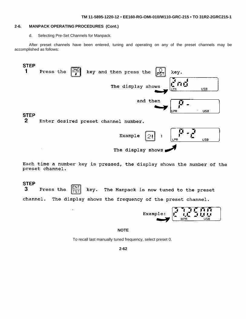
TM 11-5895-1220-12 • EE160-RG-OMI-010/W110-GRC-215 • TO 31R2-2GRC215-1
2-6. MANPACK OPERATING PROCEDURES (Cont.)
d. Selecting Pre-Set Channels for Manpack.
After preset channels have been entered, tuning and operating on any of the preset channels may beaccomplished as follows:
NOTE
To recall last manually tuned frequency, select preset 0.
2-62

TM 11-5895-1220-12 • EE160-RG-OMI-010/W110-GRC-215 • TO 31R2-2GRC215-1
2-6. MANPACK OPERATING PROCEDURES (Cont.)
e. Fine Tuning the Manpack.
NOTE
If no key entries are made within 30 seconds, the Manpack automatically exits fine tune mode, revertsback to previous mode and turns off the display back-lighting.
The Manpack will not tune below 2.0000 MHz or above 29.9999 MHz.
2-63

TM 11-5895-1220-12 • EE160-RG-OMI-010/W110-GRC-215 • TO 31R2-2GRC215-1
2-6. MANPACK OPERATING PROCEDURES (Cont.)
f. Changing Sidebands for the Manpack.
Sideband indicator LSB (lower sideband) or USB (upper sideband) light to indicate present sideband setting. Tochange sideband setting proceed as follows:
NOTE
If no key entries are made within 30 seconds, the Manpack automatically exits sideband select mode,reverts back to previous mode and turns off the display back-lighting.
2-64

TM 11-5895-1220-12 • EE160-RG-OMI-010/W110-GRC-215 • TO 31R2-2GRC215-1
2-6. MANPACK OPERATING PROCEDURES (Cont.)
g. Select Power Output Level for Manpack.
NOTE
If no key entries are made within 30 seconds, the Manpack automatically exits power select mode, revertsback to previous mode and turns off the display backlighting.
2-65
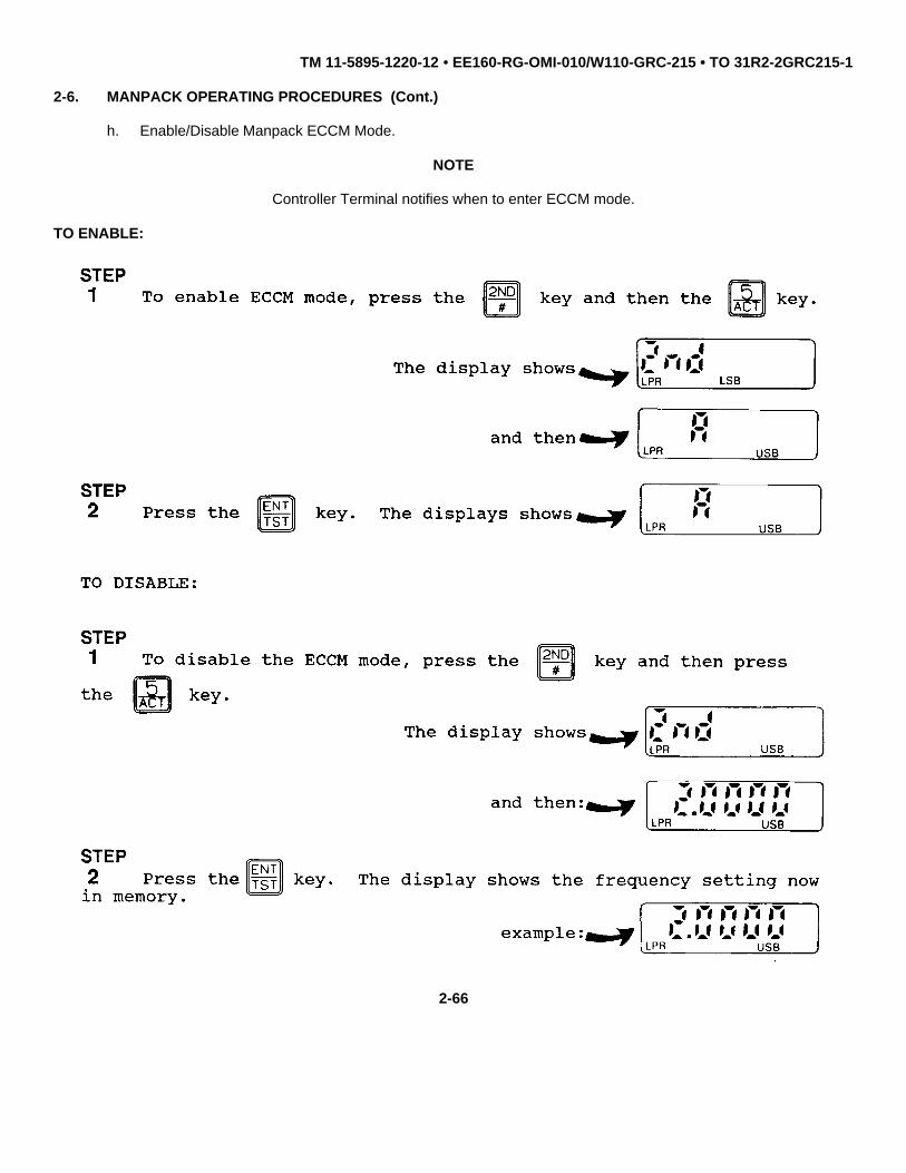
TM 11-5895-1220-12 • EE160-RG-OMI-010/W110-GRC-215 • TO 31R2-2GRC215-1
2-6. MANPACK OPERATING PROCEDURES (Cont.)
h. Enable/Disable Manpack ECCM Mode.
NOTE
Controller Terminal notifies when to enter ECCM mode.
TO ENABLE:
2-66

TM 11-5895-1220-12 • EE160-RG-OMI-010/W110-GRC-215 • TO 31R2-2GRC215-1
2-6. MANPACK OPERATING PROCEDURES (Cont.)
i. Changing/Loading TRANSEC Variables for Manpack.
NOTE
Fill device must not be connected while selecting variables.
2-67

TM 11-5895-1220-12 • EE160-RG-OMI-010/W110-GRC-215 • TO 31R2-2GRC215-1
2-6. MANPACK OPERATING PROCEDURES (Cont.)
j. Enable/Disable Manpack Secure Voice Mode.
Assembly procedures for the Manpack secure voice configuration are provided in paragraph 2-5b(2).
STEP1 On TSEC/KY-65, set POWER switch to ON and set MODE switch to CIPHER. Load TSEC/KY-65 crypto variables
(para 2-8b, step 4).
STEP2 Operate Manpack in accordance with normal Manpack operating procedures (para 2-6a through para 2-6i).
STEP3 To disable Manpack secure voice mode, set MODE switch on TSEC/KY-65 to PLAIN position or disconnect
TSEC/KY-65 from Manpack and reinstall it in equipment rack (para 2-5a).
THIS COMPLETES MANPACK OPERATING PROCEDURES
2-68

TM 11-5895-1220-12 • EE160-RG-OMI-010/W110-GRC-215 • TO 31R2-2GRC215-1
2-7. INITIAL ADJUSTMENTS, DAILY CHECKS AND SELF TEST
Automatic testing of the Team Terminal is initiated upon applying power to the I/O Unit. Refer to PMCS chart(para 2-4) for daily checks.
2-8. TEAM TERMINAL OPERATING PROCEDURES
This paragraph contains procedures to help you understand and operate the Team Terminal when in the vehicularconfiguration. Separate procedures are provided for Manpack operation (para 2-8). The I/O Unit controls all data andvoice functions in the Team Terminal vehicular configuration. Review the description and use of I/O Unit bezel keys (para2-2). Perform the procedures listed in the Interval (column B) column of the preventive maintenance checks and serviceschart. If you are going to be operating in the nonsecure data mode, remove cables from TSEC/KG-84A and connect themto the KG-84 nonsecure bypass assembly (para 2-5a(3)). Step-by-step procedures for you to operate the Team Terminalare arranged as follows:
• POWER-ON SEQUENCE (para 2-8a) - These procedures are for applying power to the Team Terminal(vehicle battery or auxiliary power) and for powering-up individual equipments.
• INITIALIZATION (para 2-8b) - These procedures are for initializing the Team Terminal from a cold-startstate. You will be instructed to load cryptographic and TRANSEC variables and then, using I/O Unitmenu-driven procedures, select voice or data, transmit power level and operating mode, set the date andyour geographic location, and enter initial frequency set.
• MESSAGE CREATION AND HANDLING (para 2-8c) - These procedures are for data messagecomposition/transmission.
• SHOW MESSAGE (para 2-8d) - These procedures allow you to view the highest priority receivedmessage.
• OPERATIONAL SET-UP (para 2-8e) - These procedures allow you to change operating parameterswhile the Team Terminal is operating normally. Operational changes are made via a set-up menu.
• CHANGING TRANSEC VARIABLES (para 2-8f) - These procedures are for changing TRANSEC variableselection after the variables have been loaded. The TRANSEC variables are normally changedautomatically. Do not change TRANSEC variables unless instructed by your controller.
• LEAVE NET (para 2-8g) - These procedures are for signing out of the data net.
2-69

TM 11-5895-1220-12 • EE160-RG-OMI-010/W110-GRC-215 • TO 31R2-2GRC215-1
2-8. TEAM TERMINAL OPERATING PROCEDURES (Cont.)
• ZEROIZE (para 2-8h) - These procedures are for zeroizing the Team Terminal. This function zeroizesthe COMSEC equipment including TSEC/KY-65, TSEC/KG-84A, and zeroizes the TRANSEC variables.
• POWER-OFF SEQUENCE (para 2-8i) - These procedures are for powering-off equipment.
• REMOTE DATA OPERATION (para 2-8j) - These procedures are for operating the Team Terminal whenconfigured for remote data operations.
• REMOTE VOICE OPERATION (para 2-8k) - These procedures are for operating the Team Terminalwhen configured for remote voice operations.
• ERROR AND STATUS MESSAGES (App F) - Provides a listing and explanation of all error and statusmessages, you may encounter while operating the Team Terminal.
WARNING
When operating from a motor generator set, ground should be installed in the motor generator area.Generator ground, systems ground and fuel static ground must not be connected together.
WARNING
When operating the Team Terminal at halt, ground the vehicle. The angle washer located on the antennabase provides a convenient location to attach a ground strap.
NOTE
The Team Terminal may be configured to accept different sources of power. In all cases you will beinstructed to place power switches to the ON positions. If a power switch trips, do not repeatedly reset;contact unit maintenance.
a. Power-On Sequence
STEP1 RFO RESET-OFF switch to OFF, if time-off-day (TOD) has already been loaded into the RFO. Set all other
equipment power switches to OFF position.
Change 1 2-70

TM 11-5895-1220-12 • EE160-RG-OMI-010/W110-GRC-215 • TO 31R2-2GRC215-1
2-8. TEAM TERMINAL OPERATING PROCEDURES (Cont.)
POWER-ON SEQUENCE (Cont.)
STEP2 Connect power source (vehicle power or auxiliary power) to Team Terminal.
• Vehicle Power - Start the vehicle. (Connect vehicle input power cable W100 to PWR IN connector onTT PS). After the motor has begun to idle smoothly, set the DC ON-OFF switch on the TT PS to ON.The POWER indicator on the TT PS and the power ON indicator on the Vehicular Adapter light.
• Auxiliary Power - Connect 115 Vac input power cable W101 (CX-13373/G) or 230 Vac input power cableW102 (CX-13372/G) as applicable) to PWR IN connector on the TT PS. Start the motor generator. Afterthe motor generator has stabilized to an even idle, set AC ON-OFF switch on the TT PS to ON. ThePOWER indicator on the TT PS and the power ON indicators on the Vehicular Adapter light.
2-71

TM 11-5895-1220-12 • EE160-RG-OMI-010/W110-GRC-215 • TO 31R2-2GRC215-1
2-8. TEAM TERMINAL OPERATING PROCEDURES (Cont.)
POWER-ON SEQUENCE (Cont)
STEP3 Check the TT PS output voltage level shown on the OUTPUT VOLTAGE meter. The voltage should be stable and
should read between +26 and +30 Vdc.
STEP4 If vehicular power is used, set the RFO ON-OFF switch on the TT PS to ON. This will enable the RFO to remain
powered-on and to retain TOD when the TT PS is powered-off.
NOTE
The RFO must remain powered-up after TOD has been obtained. If the RFO has been powered-down orif the power source has been interrupted, contact Mobile Maintenance Contact Team (MMCT) to obtainTOD. Navy personnel contact Chief Watch Officer. Air Force personnel contact Maintenance Control.
STEP5 If the RFO is in the powered-up state, proceed to step 6. Otherwise, proceed as follows:
• On RFO, set LAMPS switch to BRIGHT and set RESET-OFF switch to RESET. The EXT POWERindicator lights and the SET CLOCK indicator lights momentarily. The COLD OSC indicator lights toindicate internal oscillator is cold. Allow up to 30 minutes warmup for stabilizing internal oscillator (COLDOSC indicator goes out after warm-up period is over).
• Press BATT TEST switch and ensure BATTERY STATUS indicator lights (if the indicator does not light,contact genera support maintenance). Release BATT TEST switch.
• Contact MMCT or a Force Terminal to obtain TOD for the Team Terminal. Refer to Paragraph 3-11 forcable connection and loading procedure.
• When TOD is available to the Team Terminal, press and release the RCV TOD switch on the RFO. TheSET CLOCK indicator lights. Upon receipt of a valid TOD, the SET CLOCK indicator will go off (the RFOFAULT indicator will light if TOD is not transferred within 7 seconds. The SET CLOCK indicator will lightif the RFO loses TOD. If this occurs, repeat this step to reload the TOD.
• Set LAMPS switch for desired indicator lamp intensity (BRIGHT-DIM-OFF).
2-72

TM 11-5895-1220-12 • EE160-RG-OMI-010/W110-GRC-215 • TO 31R2-2GRC215-1
2-8. TEAM TERMINAL OPERATING PROCEDURES (Cont.)
POWER-ON SEQUENCE (Cont.)
STEP6 On RN Modem, set PWR ON-OFF switch to PWR ON. The PWR ON indicator lights. The BIT indicator blinks for
approximately 20 seconds during its BIT routine.
STEP7 On TSEC/KG-84A (if configured for secure operations), set POWER ON-OFF switch to ON. The POWER
indicator and the ALARM indicator light. The RN modem BIT indicator will light, and will not go out until KG-84A variable isloaded, and I/O is powered up and initialized.
STEP8 Power-up the TSEC/KY-65.
• Pull out and set POWER switch to ON.
• Set and hold INT BAT-AUDIO-EXT BAT switch to EXT BAT. The meter on TSEC/KY-65 should indicatebetween +12.0 and +13.5 Vdc (external source voltage below +10.2 Vdc will cause TSEC/KY-65 tosound a battery fail alarm tone). Release INT BAT-AUDIO-EXT BAT switch.
• Connect Handset to KY connector on the RT. Turn the TSEC/KY-65 VOLUME control in a clockwisedirection to a mid-range position.
• Set TSEC/KY-65 SYNC MODE switch to HF.
NOTE
Mechanical tuning of the ATU may be heard upon power up of the RT.
2-73

TM 11-5895-1220-12 • EE160-RG-OMI-010/W110-GRC-215 • TO 31R2-2GRC215-1
2-8. TEAM TERMINAL OPERATING PROCEDURES (Cont.)
POWER-ON SEQUENCE (Cont.)
NOTE
Upon initial power-up, the RT is automatically set to low power (LPR) and to upper sideband (USB).
NOTE
Upon power-up of the I/O Unit, the D/K assembly may briefly show (for one second or less) the messageHOST LINK ATTEMPTING. This message occurs while the D/K assembly is attempting to establishcommunications with the processor in the controller assembly.
STEP10 On I/O Unit, set POWER switch to ON.
• All indicators on the I/O Unit light and the alarm sounds for approximately two seconds and thenautomatically turn off (PWR indicator on D/K assembly and POWER indicator on controller assemblyremain lighted.
• The D/K assembly shows "ENSURE ALL EQUIPMENT IS POWERED-ON AT THIS TIME"; proceed toinitialization procedures (para 2-8b).
THIS COMPLETES TEAM TERMINAL POWER-UP PROCEDURES
2-74

TM 11-5895-1220-12 • EE160-RG-OMI-010/W110-GRC-215 • TO 31R2-2GRC215-1
2-8. TEAM TERMINAL OPERATING PROCEDURES (Cont.)
b. Initialization
INITIALIZATION
CAUTION
Do not activate bezel keys or screen touchpoints with any sharp item. Use fingers, gloves or other softand rounded item. The touchpoints are more sensitive to activation with finger tips than the fleshy portionof the finger.
NOTE
The first four steps of initialization provide an option for you to run BIT on the D/K assembly via four testscreens. If any fault conditions are observed, determine if you can continue operating with the fault; that isdecide if the failed area of the display is critical to operation of the I/O Unit.
STEP1 The D/K assembly shows the message ENSURE ALL EQUIPMENT IS POWERED-ON AT THIS TIME.
• Check to ensure all equipment is powered-up.
• Press NEXT MENU to continue.
2-75

TM 11-5895-1220-12 • EE160-RG-OMI-010/W110-GRC-215 • TO 31R2-2GRC215-1
2-8. TEAM TERMINAL OPERATING PROCEDURES (Cont.)
INITIALIZATION (Cont.)
STEP2 The D/K assembly shows the message FOR SECURE OPERATIONS, LOAD CRYPTO VARIABLES AT THIS
TIME.
• For secure operations:
•• Load TSEC/KG-84A cryptographic variables (step 3).
•• Load TSEC/KY-65 cryptographic variables (step 4).
•• Load ECCM Module TRANSEC variables (step 5).
• For nonsecure operations:
•• Ensure TSEC/KG-84A is removed from rack assembly and the KG-84 nonsecure bypass assemblyis connected (para 2-5a(3)).
•• On TSEC/KY-65, set MODE switch to PLAIN position.
•• Load ECCM Module TRANSEC variables (step 5).
2-76

TM 11-5895-1220-12 • EE160-RG-OMI-010/W110-GRC-215 • TO 31R2-2GRC215-1
2-8. TEAM TERMINAL OPERATING PROCEDURES (Cont.)
INITIALIZATION (Cont.)
STEP3 Load TSEC/KG-84A cryptographic variables.
• Remove dust cover from FILL connector on TSEC/KG-84A. Connect General Purpose Tape ReaderKOI-18 (fill device) to FILL connector using a fill cable.
NOTE
The specified tape segment for the fill device is identified by the Communications Electronics OperatingInstructions (CEOI) or other operational doctrine.
• On TSEC/KG-84A, pull outward and set ENABLE-ZEROIZE switch to ZEROIZE position. The POWERand the ALARM indicators go off. Return the switch to the ENABLE position. The POWER and theALARM indicator come back on.
• Set MODE switch to LDU position.
• Push up momentarily and then release the INITIATE-IND TEST switch. Observe that the PARITYindicator blinks once. If it does blink once and remains off, proceed. If the PARITY indicator does notblink or remains lighted, repeat this step. Continual failure of the PARITY indicator to blink indicates aproblem with the TSEC/KG-84A. Report the problem to unit maintenance.
2-77

TM 11-5895-1220-12 • EE160-RG-OMI-010/W110-GRC-215 • TO 31R2-2GRC215-1
2-8. TEAM TERMINAL OPERATING PROCEDURES (Cont.)
INITIALIZATION (Cont.)
STEP3 (Cont.)
• Set MODE switch to LDX position (switch remains in LDX position until all X registers to be filled aresuccessfully filled).
• Set the X-VAR switch to 1.
• Push up momentarily and then release INITIATE-IND TEST switch. Observe that the PARITY indicatorlights. If not, repeat this step. If the PARITY indicator still does not light, contact unit maintenance.
• Insert the specified tape segment into the fill device. Pull tape segment slowly and in one continuousmotion through fill device. The PARITY indicator will go off if load is successful. If the variable load is notaccepted, the PARITY indicator will remain lighted and the variable must be reloaded.
• Set the X-VAR switch to 2, 3, 4, as specified in the CEOI and load remaining variables (repeat theprevious two steps).
• When all variables are loaded, set MODE switch to OPR. The ALARM indicator goes off and the FULLOPR indicator lights.
NOTE
If the ALARM indicator continues to light or if the FULL OPR indicator does not light, the TSEC/KG-84A isnot in a secure state for operations. Secure communications cannot be initiated. Notify the TerminalSecurity Officer immediately.
• Disconnect the fill device from the FILL connector on the TSEC/KG-84A. Replace fill connector dustcover.
2-78

TM 11-5895-1220-12 • EE160-RG-OMI-010/W110-GRC-215 • TO 31R2-2GRC215-1
2-8. TEAM TERMINAL OPERATING PROCEDURES (Cont.)
INITIALIZATION (Cont.)
STEP4 Load TSEC/KY-65 cryptographic variables.
• Remove FILL connector dust cover and connect fill device to FILL connector on TSEC/KY-65 using a fillcable.
• Set TSEC/KY-65 MODE switch to CIPHER.
Listen for cryptoalarm cryptoalarm tone inHandset.
• Set TSEC/KY-65 FILL switch to position to befilled (1, 2, or 3).
• Insert tape leader into fill device.
• Turn TSEC/KY-65 DELAY OUT-DELAY IN-SIG CLR switch to SIG CLR position and release. The switch
is spring loaded and will return to DELAY IN when released.
• Pull tape through fill device at a moderate rate. Crypto-alarm tone in the Handset should stop, indicatinga successful fill.
• Repeat loading steps until all desired variables areloaded.
• Disconnect fill device from TSEC/KY-65 FILLconnector. Replace cover on TSEC/KY-65 FILLconnector.
STEP5 Load ECCM Module TRANSEC variables.
• On ECCM Module, remove connector cover fromFILL connector. Connect fill device to FILLconnector using fill cable. Insert tape leader into filldevice.
The ECCM Module display shows:
2-79

TM 11-5895-1220-12 • EE160-RG-OMI-010/W110-GRC-215 • TO 31R2-2GRC215-1
2-8. TEAM TERMINAL OPERATING PROCEDURES (Cont.)
INITIALIZATION (Cont.)
2-80

TM 11-5895-1220-12 • EE160-RG-OMI-010/W110-GRC-215 • TO 31R2-2GRC215-1
2-8. TEAM TERMINAL OPERATING PROCEDURES (Cont.)
INITIALIZATION (Cont.)
STEP6 The D/K assembly shows the message DO YOU WISH TO PERFORM THE DISPLAY/KEYPAD TEST?. Press
the YES touchpoint to proceed to the DISPLAY/KEYPAD test. Press the NO touchpoint to proceed to whole terminal BIT.
• If YES was selected, proceed to STEP 7.
• If NO was selected, proceed to STEP 10.
2-81

TM 11-5895-1220-12 • EE160-RG-OMI-010/W110-GRC-215 • TO 31R2-2GRC215-1
2-8. TEAM TERMINAL OPERATING PROCEDURES (Cont.)
INITIALIZATION (Cont.)
STEP6.1 Observe display and check for a diagonal straight line.
• If line is present, press PASS touchpoint. The display automatically proceeds to the next test.
• If line is not present, press FAIL touchpoint to indicate a failure. The display automatically proceeds tonext test.
STEP7 Observe that the D/K assembly is completely lighted. If lighted, press PASS touchpoint. If areas of the D/K
assembly are not lighted to the extent that operation of the I/O Unit cannot continue, press FAIL touchpoint.
Change 1 2-82

TM 11-5895-1220-12 • EE160-RG-OMI-010/W110-GRC-215 • TO 31R2-2GRC215-1
2-8. TEAM TERMINAL OPERATING PROCEDURES (Cont.)
INITIALIZATION (Cont.)
STEP8 The D/K assembly shows 66 lighted touchpoints. Press and release each touchpoint. Check that each touchpoint
goes off as it is released. If any touchpoint fails to go off, depress any bezel key to indicate test failure.
2-83

TM 11-5895-1220-12 • EE160-RG-OMI-010/W110-GRC-215 • TO 31R2-2GRC215-1
2-8. TEAM TERMINAL OPERATING PROCEDURES (Cont.)
INITIALIZATION (Cont.)
STEP9 The D/K assembly shows 34 lighted squares around the edge of the display corresponding to each bezel function
switch (bezel key). Select and depress each bezel key and observe that its corresponding lighted square goes off. If anylighted square fails to go off, press FAIL touchpoint.
2-84
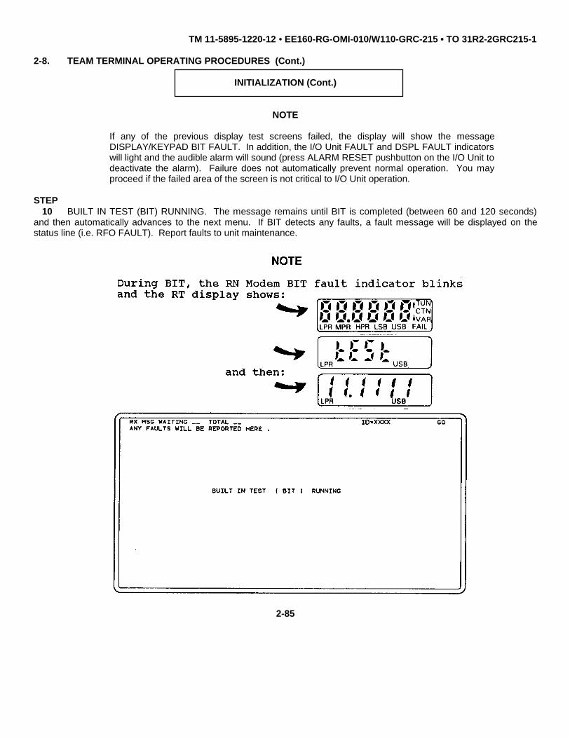
TM 11-5895-1220-12 • EE160-RG-OMI-010/W110-GRC-215 • TO 31R2-2GRC215-1
2-8. TEAM TERMINAL OPERATING PROCEDURES (Cont.)
INITIALIZATION (Cont.)
NOTE
If any of the previous display test screens failed, the display will show the messageDISPLAY/KEYPAD BIT FAULT. In addition, the I/O Unit FAULT and DSPL FAULT indicatorswill light and the audible alarm will sound (press ALARM RESET pushbutton on the I/O Unit todeactivate the alarm). Failure does not automatically prevent normal operation. You mayproceed if the failed area of the screen is not critical to I/O Unit operation.
STEP10 BUILT IN TEST (BIT) RUNNING. The message remains until BIT is completed (between 60 and 120 seconds)
and then automatically advances to the next menu. If BIT detects any faults, a fault message will be displayed on thestatus line (i.e. RFO FAULT). Report faults to unit maintenance.
2-85

TM 11-5895-1220-12 • EE160-RG-OMI-010/W110-GRC-215 • TO 31R2-2GRC215-1
2-8. TEAM TERMINAL OPERATING PROCEDURES (Cont.)
INITIALIZATION (Cont.)
STEP11 Input your terminal ID number.
• Using the numbered touchpoints, shown on the D/K assembly, input four-digit terminal ID number (0513 -1023) and then press ENTER bezel key.
• The D/K assembly shows the message prompt PRESS NEXT MENU TO CONTINUE. Check your entry.If correct, press NEXT MENU bezel key. If incorrect, re-enter terminal ID number.
2-86

TM 11-5895-1220-12 • EE160-RG-OMI-010/W110-GRC-215 • TO 31R2-2GRC215-1
2-8. TEAM TERMINAL OPERATING PROCEDURES (Cont.)
INITIALIZATION (Cont.)
STEP12 The D/K assembly shows MODE OF OPERATION menu. Select data mode by pressing DATA touchpoint or
select voice mode by pressing VOICE touchpoint. The selected touchpoint lights. Press NEXT MENU bezel key tocontinue.
• If you selected VOICE, proceed to step 13.
• If you selected DATA, proceed to step 21.
2-87

TM 11-5895-1220-12 • EE160-RG-OMI-010/W110-GRC-215 • TO 31R2-2GRC215-1
2-8. TEAM TERMINAL OPERATING PROCEDURES (Cont.)
INITIALIZATION (Cont.)
STEP13 The D/K assembly shows the VOICE MODE FREQUENCY SELECTION menu.
• To enable ECCM voice mode, input two-digit ECCM frequency code and then press ENTER bezel key.The D/K assembly shows the message prompt PRESS NEXT MENU TO CONTINUE. Check your entry.If correct, press NEXT MENU bezel key and proceed to step 14. If incorrect, re-enter frequency code.
• To enable NON-ECCM voice mode, press HERE touchpoint. The HERE touchpoint lights to show yourselection. Press NEXT MENU bezel key to continue and proceed to step 16.
2-88

TM 11-5895-1220-12 • EE160-RG-OMI-010/W110-GRC-215 • TO 31R2-2GRC215-1
2-8. TEAM TERMINAL OPERATING PROCEDURES (Cont.)
INITIALIZATION (Cont.)
STEP14 The D/K assembly shows TRANSMITTER POWER LEVEL menu. Select power level.
• Press touchpoint to select HIGH, MEDIUM, or LOW. The selected touchpoint lights.
• Press NEXT MENU bezel key to continue.
2-89

TM 11-5895-1220-12 • EE160-RG-OMI-010/W110-GRC-215 • TO 31R2-2GRC215-1
2-8. TEAM TERMINAL OPERATING PROCEDURES (Cont.)
INITIALIZATION (Cont.)
STEP15 The D/K assembly shows the message prompt ECCM VOICE MODE ENABLED. Initialization for ECCM voice
operation is complete. Connect Handset to KY connector on RT and establish point-to-point or broadcast links utilizingstandard radio procedures.
WARNINGI
Dangerous RF power levels exist on and around the antenna during operation. Do not stand closer than40 inches to the antenna when transmitting. Failure to heed this warning may result in death or seriousinjury.
NOTE
To exit the voice mode and initialize the data mode, press the DATA MODE bezel key. This will start thedata mode menu sequence (step 21).
2-90

TM 11-5895-1220-12 • EE160-RG-OMI-010/W110-GRC-215 • TO 31R2-2GRC215-1
2-8. TEAM TERMINAL OPERATING PROCEDURES (Cont.)
INITIALIZATION (Cont.)
STEP16 The D/K assembly shows VOICE FREQUENCY ENTRY menu. Press touchpoint to select MANUAL
FREQUENCY ENTRY or FREQUENCY CODE ENTRY. The selected touchpoint lights and the D/K assembly shows themessage prompt PRESS NEXT MENU TO CONTINUE. Press NEXT MENU bezel key.
• If you selected MANUAL FREQUENCY ENTRY, proceed to step 17.
• If you selected FREQUENCY CODE ENTRY, proceed to step 18.
2-91

TM 11-5895-1220-12 • EE160-RG-OMI-010/W110-GRC-215 • TO 31R2-2GRC215-1
2-8. TEAM TERMINAL OPERATING PROCEDURES (Cont.)
INITIALIZATION (Cont.)
STEP17 The D/K assembly prompts you to LOAD NEW FREQUENCY. To load new frequency:
• Press touchpoint to select UPPER SIDE BAND or LOWER SIDE BAND. The selected touchpoint lights.
• Using the numbered touchpoints, input the frequency. The frequency selection in MHz is shown on theD/K assembly. Press ENTER bezel key.
• The D/K assembly shows the message prompt PRESS NEXT MENU TO CONTINUE. Check your entry.If correct, press NEXT MENU bezel key and proceed to step 19. If incorrect, re-enter.
2-92

TM 11-5895-1220-12 • EE160-RG-OMI-010/W110-GRC-215 • TO 31R2-2GRC215-1
2-8. TEAM TERMINAL OPERATING PROCEDURES (Cont.)
INITIALIZATION (Cont.)
STEP18 The D/K assembly prompts you to LOAD NEW FREQUENCY CODE. To load frequency code:
• Input two-digit frequency code. The D/K assembly shows your selection. Press ENTER bezel key.
• The D/K assembly shows the message prompt PRESS NEXT MENU TO CONTINUE. Check your entry.If correct, press NEXT MENU bezel key and proceed to step 19. If incorrect, re-enter frequency code.
2-93

TM 11-5895-1220-12 • EE160-RG-OMI-010/W110-GRC-215 • TO 31R2-2GRC215-1
2-8. TEAM TERMINAL OPERATING PROCEDURES (Cont.)
INITIALIZATION (Cont.)
STEP19 The D/K assembly shows the TRANSMITTER POWER LEVEL menu. Select transmitter power level:
• Press touchpoint to select HIGH, MEDIUM or LOW power level. The selected touchpoint lights.
• Press NEXT MENU bezel key to continue.
2-94

TM 11-5895-1220-12 • EE160-RG-OMI-010/W110-GRC-215 • TO 31R2-2GRC215-1
2-8. TEAM TERMINAL OPERATING PROCEDURES (Cont.)
INITIALIZATION (Cont.)
STEP20 The D/K assembly shows the message prompt NON-ECCM VOICE MODE ENABLED. Initialization for NON-
ECCM voice mode is complete. Connect Handset to KY connector on RT and establish point-to-point or broad-cast linksutilizing standard radio procedures.
WARNING
Dangerous RF power levels exist on and around the antenna during operation. Do not stand closer than40 inches to the antenna when transmitting. Failure to heed this warning may result in death or seriousinjury.
NOTE
To exit the voice mode and initialize the data mode, press the DATA MODE bezel key. This will start thedata mode menu sequence (step 21).
2-95

TM 11-5895-1220-12 • EE160-RG-OMI-010/W110-GRC-215 • TO 31R2-2GRC215-1
2-8. TEAM TERMINAL OPERATING PROCEDURES (Cont.)
INITIALIZATION (Cont.)
STEP21 The D/K assembly shows the SET DATE menu. Enter the date.
• Using numbered touchpoints, input two-digit number for YEAR, MONTH, and DAY. Press ENTER bezelkey for each two-digit input.
• The D/K assembly shows the message prompt PRESS NEXT MENU TO CONTINUE. Check yourentries. If correct, press NEXT MENU bezel key. If incorrect, re-enter the date.
2-96

TM 11-5895-1220-12 • EE160-RG-OMI-010/W110-GRC-215 • TO 31R2-2GRC215-1
2-8. TEAM TERMINAL OPERATING PROCEDURES (Cont.)
INITIALIZATION (Cont.)
STEP22 Enter your geographic location.
• Using keypad touchpoints, input your geographic location. The D/K assembly shows your input. PressENTER bezel key.
• The D/K assembly shows the message prompt PRESS NEXT MENU TO CONTINUE. Check your entry.If correct, press NEXT MENU bezel key. If incorrect, re-enter geographic location.
2-97

TM 11-5895-1220-12 • EE160-RG-OMI-010/W110-GRC-215 • TO 31R2-2GRC215-1
2-8. TEAM TERMINAL OPERATING PROCEDURES (Cont.)
INITIALIZATION (Cont.)
STEP23 Select NON-ECCM data mode frequency.
• Using the keypad touchpoints, input two-digit frequency code. The D/K assembly shows your input.Press ENTER bezel key.
• After the first frequency code has been entered, the D/K assembly shows the message prompt PRESSNEXT MENU TO CONTINUE. Press NEXT MENU bezel key or continue entering up to 12 frequencycodes.
2-98

TM 11-5895-1220-12 • EE160-RG-OMI-010/W110-GRC-215 • TO 31R2-2GRC215-1
2-8. TEAM TERMINAL OPERATING PROCEDURES (Cont.)
INITIALIZATION (Cont.)
STEP24 Select ECCM data mode (HOPSET) frequency.
• Using the keypad touchpoints, input two-digit frequency code. The D/K assembly shows your input.Press ENTER bezel key.
• After the first frequency code has been entered, the D/K assembly shows the message prompt PRESSNEXT MENU TO CONTINUE. Press NEXT MENU bezel key or continue entering up to 12 frequencycodes.
2-99

TM 11-5895-1220-12 l EE160-RG-OMI-010/W110-GRC-215 l TO 31R2-2GRC215-1
2-8. TEAM TERMINAL OPERATING PROCEDURES (Cont.)
INITIALIZATION (Cont.)
STEP25 Select cryptographic variable.
• Press touchpoint to select VARIABLE 1, VARIABLE 2, VARIABLE 3, or VARIABLE 4. The selectedtouchpoint lights.
• Press NEXT MENU bezel key to continue.
2-100

TM 11-5895-1220-12 • EE160-RG-OMI-010/W110-GRC-215 • TO 31R2-2GRC215-1
2-8. TEAM TERMINAL OPERATING PROCEDURES (Cont.)
INITIALIZATION (Cont.)
STEP26 Select data operating mode.
• Press touchpoint to select NON-ECCM, TRAINING, or ECCM. The selected touchpointlights.
• Press NEXT MENU bezel key to continue.
2-101

TM 11-5895-1220-12 • EE160-RG-OMI-010/W110-GRC-215 • TO 31R2-2GRC215-1
2-8. TEAM TERMINAL OPERATING PROCEDURES (Cont.)
INITIALIZATION (Cont.)
STEP27 Enter the message destination.
• Using the numbered touchpoints, input four-digit destination terminal ID number (0001 -1023). The D/K assembly shows your input. Press ENTER bezel key.
• Using the numbered touchpoints, input destination I/O number (0 - 5). The D/K assemblyshows your input. Press ENTER bezel key.
• The D/K assembly shows the message prompt PRESS NEXT MENU TO CONTINUE.Check your entries. If correct, press NEXT MENU bezel key. If incorrect, re-enter messagedestination.
2-102

TM 11-5895-1220-12 • EE160-RG-OMI-010/W110-GRC-215 • TO 31R2-2GRC215-1
2-8. TEAM TERMINAL OPERATING PROCEDURES (Cont.)
INITIALIZATION (Cont.)
STEP28 Select transmitter power level.
• Press touchpoint to select HIGH, MEDIUM, or LOW power level. The selectedtouchpoint lights.
• Press NEXT MENU bezel key to continue.
2-103

TM 11-5895-1220-12 • EE160-RG-OMI-010/W110-GRC-215 • TO 31R2-2GRC215-1
2-8. TEAM TERMINAL OPERATING PROCEDURES (Cont.)
INITIALIZATION (Cont.)
STEP29 Enter subnet number.
• Using the numbered touchpoints, input three-digit subnet number (001 - 144). The D/Kassembly shows your input. Press ENTER bezel key.
• The D/K assembly shows the message prompt PRESS NEXT MENU TO CONTINUE.
Check your entry. If correct, press NEXT MENU bezel key. If incorrect, re-enter thesubnet number.
2-104
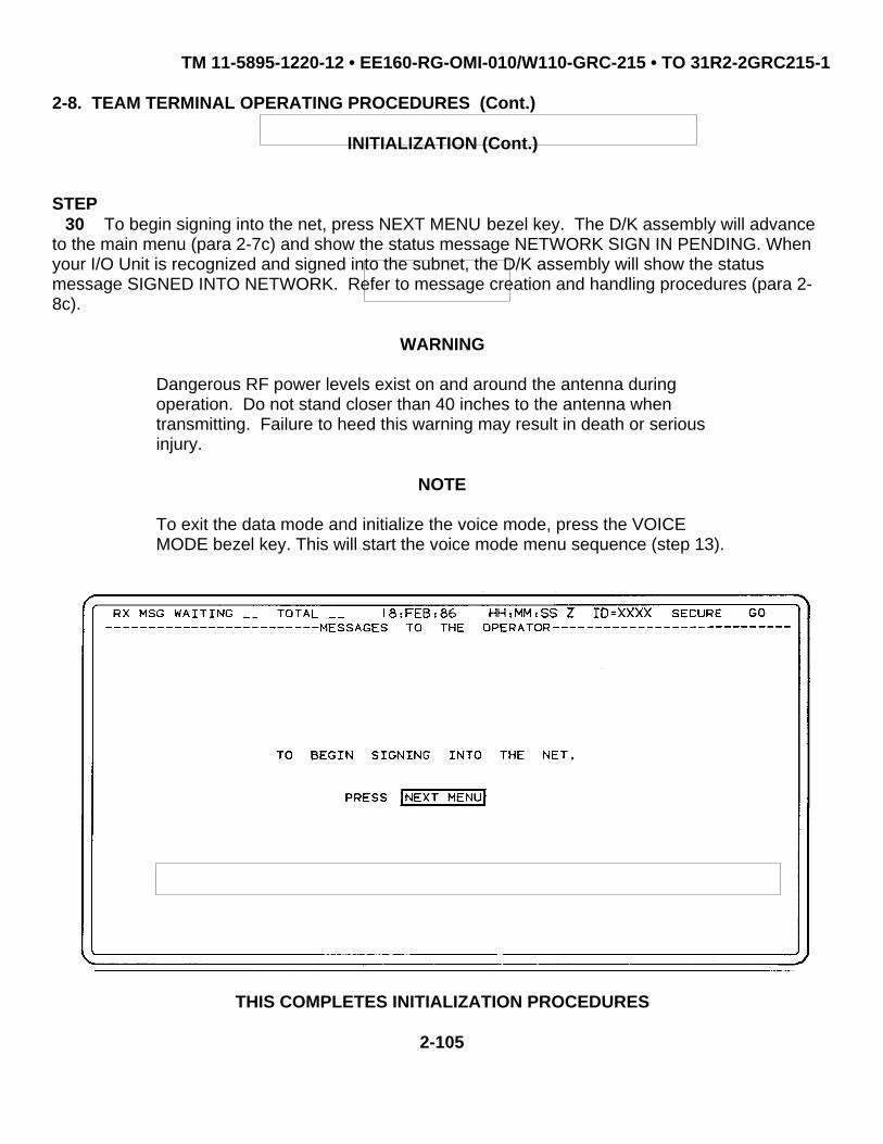
TM 11-5895-1220-12 • EE160-RG-OMI-010/W110-GRC-215 • TO 31R2-2GRC215-1
2-8. TEAM TERMINAL OPERATING PROCEDURES (Cont.)
INITIALIZATION (Cont.)
STEP30 To begin signing into the net, press NEXT MENU bezel key. The D/K assembly will advance
to the main menu (para 2-7c) and show the status message NETWORK SIGN IN PENDING. Whenyour I/O Unit is recognized and signed into the subnet, the D/K assembly will show the statusmessage SIGNED INTO NETWORK. Refer to message creation and handling procedures (para 2-8c).
WARNING
Dangerous RF power levels exist on and around the antenna duringoperation. Do not stand closer than 40 inches to the antenna whentransmitting. Failure to heed this warning may result in death or seriousinjury.
NOTE
To exit the data mode and initialize the voice mode, press the VOICEMODE bezel key. This will start the voice mode menu sequence (step 13).
THIS COMPLETES INITIALIZATION PROCEDURES
2-105

TM 11-5895-1220-12 • EE160-RG-OMI-010/W110-GRC-215 • TO 31R2-2GRC215-1
2-8. TEAM TERMINAL OPERATING PROCEDURES (Cont.)
c. Message Creation and Handling
MESSAGE CREATION AND HANDLING
The main menu allows you to select a canned message, select the message in the edit buffer,or you can compose a new message. Upon message selection, the message is retrieved anddisplayed on the screen for composition, review, and transmission.
STEP1 Select type of message to be processed.
• If you wish to recall a canned message or if you wish to compose/edit from a cannedmessage for subsequent transmission, press RECALL CANNED MESSAGE DIRECTORYtouchpoint and then press NEXT MENU to continue. Proceed to step 2.
• If you wish to recall your last edited message, press RECALL LAST EDITED MESSAGEtouchpoint and then press NEXT MENU to continue. Proceed to step 3 for compose/editprocedure.
• If you wish to create a new message, press CREATE NEW MESSAGE touchpoint andthen press NEXT MENU to continue. Proceed to step 3 for compose/edit procedure.
2-106

TM 11-5895-1220-12 • EE160-RG-OMI-010/W110-GRC-215 • TO 31R2-2GRC215-1
2-8. TEAM TERMINAL OPERATING PROCEDURES (Cont.)
MESSAGE CREATION AND HANDLING (Cont.)
STEP2 Select canned message.
• Press touchpoint for the canned message you wish to recall. The selected touchpointlights.
• The D/K assembly shows the message prompt PRESS NEXT MENU TO CONTINUE.Press NEXT MENU bezel key.
2-107

TM 11-5895-1220-12 • EE160-RG-OMI-010/W110-GRC-215 • TO 31R2-2GRC215-1
2-8. TEAM TERMINAL OPERATING PROCEDURES (Cont.)
MESSAGE CREATION AND HANDLING (Cont.)
STEP3 Using the keyboard-type touchpoints on the D/K assembly, compose/edit the message (the
message is displayed above the keypad touchpoint area). When in compose/edit mode, the followingbezel edit keys are enabled:
• INSERT - Use to insert a new character where the cursor is currently positioned. Allcharacter inputs are inserted at the position of the cursor until the INSERT bezel key ispressed a second time (INSERT ON will be shown on the D/K assembly when INSERTmode is activated).
• DELETE - Use to delete the character from the current position. All characters to the rightof the cursor will move to the left.
• ROLL UP, ROLL DOWN - Use to scroll the screen up or down one half page (four lines) ata time.
• ↑↓ - Use to move cursor up or down the screen one line at a time. • ← → - Use to move the cursor left or right.
• ENTER - Moves cursor to next line or new line.
2-108

TM 11-5895-1220-12 • EE160-RG-OMI-010/W110-GRC-215 • TO 31R2-2GRC215-1
2-8. TEAM TERMINAL OPERATING PROCEDURES (Cont.)
MESSAGE CREATION AND HANDLING (Cont.)
STEP4 Press XMT bezel key to transmit your message or press NEXT MENU to return to the main
menu. Your message is stored and can be recalled by selecting RECALL LAST EDITED MESSAGEfrom the main menu (step 1).
NOTE
The transmission sequence is guarded. This means the entire messagemust be displayed on the screen and reviewed prior to actual release fortransmission. You can cancel the transmit function prior to actual release,by pressing Main MENU bezel key or the ABORT bezel key to return tomain menu.
STEP5 The D/K assembly shows the first page of your message. Review entire message.
• Press ROLL UP bezel key to roll through message for review. • If message requires editing, press PRIOR MENU bezel key to return to the compose/edit
screen (step 3) and edit your message.
• Maximum length of transmit or receive messages is 200 characters.

2-109

TM 11-5895-1220-12 • EE160-RG-OMI-010/W110-GRC-215 • TO 31R2-2GRC215-1
2-8. TEAM TERMINAL OPERATING PROCEDURES (Cont.)
MESSAGE CREATION AND HANDLING (Cont.)
STEP5 (Cont.)
• After entire message has been reviewed, the D/K assembly will prompt you to PRESSNEXT MENU TO CONTINUE. Press NEXT MENU bezel key.
2-110

TM 11-5895-1220-12 • EE160-RG-OMI-010/W110-GRC-215 • TO 31R2-2GRC215-1
2-8. TEAM TERMINAL OPERATING PROCEDURES (Cont.)
MESSAGE CREATION AND HANDLING (Cont.)
STEP6 The D/K assembly shows the MESSAGE SECURITY menu with the message ONLY
TOUCHPOINTS ARE VALID (meaning you must first make a selection using the touchpoints beforepressing any bezel key.
• Select message priority by pressing HIGH PRIORITY touchpoint or LOW PRIORITYtouchpoint. The selected touchpoint lights.
• Select classification by pressing touchpoint for SECRET, CONFIDENTIAL, orUNCLASSIFIED. The selected touchpoint lights.
• Press NEXT MENU to guard the message.
• Press XMT bezel key to release message; the D/K assembly returns to the Main Menu(step 1).
THIS COMPLETES MESSAGE CREATION AND HANDLING PROCEDURES
2-111

TM 11-5895-1220-12 • EE160-RG-OMI-010/W110-GRC-215 • TO 31R2-2GRC215-1
2-8. TEAM TERMINAL OPERATING PROCEDURES (Cont.)
d. Show Message
SHOW MESSAGE
NOTE
The I/O Unit audible alarm sounds and the MSG RECEIPT indicator lightsupon receipt of a message. When activated, the audible alarm may bereset by pressing the ALARM RESET switch on the I/O Unit.
You cannot select which received message to view first. The D/Kassembly chooses the highest priority message received which has notyet been read.
You can escape the show message function by pressing either MAINMENU bezel key or ABORT bezel key without affecting the receivedmessage. The message is held in storage until deleted or overwritten.
STEP1 Press the SHOW MSG bezel key. The D/K assembly shows the highest priority received
message and the message security.
2-112
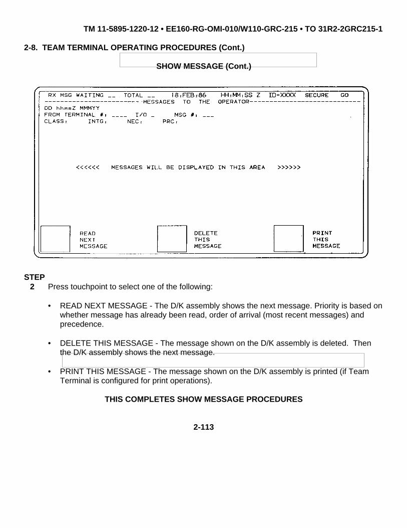
TM 11-5895-1220-12 • EE160-RG-OMI-010/W110-GRC-215 • TO 31R2-2GRC215-1
2-8. TEAM TERMINAL OPERATING PROCEDURES (Cont.)
SHOW MESSAGE (Cont.)
STEP2 Press touchpoint to select one of the following:
• READ NEXT MESSAGE - The D/K assembly shows the next message. Priority is based onwhether message has already been read, order of arrival (most recent messages) andprecedence.
• DELETE THIS MESSAGE - The message shown on the D/K assembly is deleted. Thenthe D/K assembly shows the next message.
• PRINT THIS MESSAGE - The message shown on the D/K assembly is printed (if TeamTerminal is configured for print operations).
THIS COMPLETES SHOW MESSAGE PROCEDURES
2-113

TM 11-5895-1220-12 • EE160-RG-OMI-010/W110-GRC-215 • TO 31R2-2GRC215-1
2-8. TEAM TERMINAL OPERATING PROCEDURES (Cont.)
e. Operational Set-up
OPERATIONAL SET-UP
The operational set-up function allows you to change any of the operational parameters for theTeam Terminal after power-up initialization.
STEP1 Press the SET UP bezel key; the D/K assembly shows the SET UP MENU.
NOTE
After operational parameters have been changed, the D/K assembly willreturn to the SET UP MENU. To exit operational set up at any time, pressthe MAIN MENU bezel key. Pressing the NEXT MENU bezel key beforemaking a selection will cause the D/K assembly to return to the last menuprior to going into the set up mode.
Change 1 2-114

TM 11-5895-1220-12 • EE160-RG-OMI-010/W110-GRC-215 • TO 31R2-2GRC215-1
2-8. TEAM TERMINAL OPERATING PROCEDURES (Cont.)
OPERATIONAL SET-UP (Cont.)
STEP2 To change operational parameters, press touchpoint to make your selection and then press
NEXT MENU to continue. Proceed to the applicable step in initialization procedures (para 2-8b).
• LOCATION STEP 22
• POWER LEVEL STEP 28
• MESSAGE DESTINATION STEP 27
• SUBNET NUMBER STEP 29
• CRYPTO VARIABLE STEP 25
• VOICE FREQUENCY ENTRY STEP 13
• MANUAL FREQUENCY ENTRY STEP 17
• NON-ECCM DATA FREQUENCY ENTRY STEP 23
• ECCM DATA FREQUENCY ENTRY STEP 24
• NON-ECCM/ECCM/TRAINING STEP 26
• DATE STEP 21
THIS COMPLETES OPERATIONAL SET-UP PROCEDURES
2-115

TM 11-5895-1220-12 • EE160-RG-OMI-010/W110-GRC-215 • TO 31R2-2GRC215-1
2-8. TEAM TERMINAL OPERATING PROCEDURES (Cont.)
f. Changing TRANSEC Variables
CHANGING TRANSEC VARIABLES
This procedure is for changing TRANSEC variable selection after the variables have beenloaded (and more than one variable have been loaded in accordance with paragraph 2-7b, step 9).Do not perform this procedure unless instructed by your controller.
NOTE
Fill device must not be connected to ECCM Module while changing variables.
THIS COMPLETES PREOCEDURES FOR CHANGING TRANSEC VARIABLES
2-116

TM 11-5895-1220-12 • EE160-RG-OMI-010/W110-GRC-215 • TO 31R2-2GRC215-1
2-8. TEAM TERMINAL OPERATING PROCEDURES (Cont.)
g. Leave Net Procedures
LEAVE NET PROCEDURE
STEP1 Press LEAVE NET bezel key.
STEP2 The D/K assembly shows the prompt message YOU HAVE PRESSED THE LEAVE NET KEY
!! ARE YOU SURE YOU WANT TO SIGN OUT OF THE NET ?
• If you are sure you want to sign out of the net, press the YES touchpoint and then pressthe NEXT MENU bezel key to continue.
• If you do not want to sign out of the net, press the NO touchpoint and then press the NEXTMENU bezel key to continue. The D/K assembly returns to the last menu prior to enteringthe leave net mode.
2-117

TM 11-5895-1220-12 • EE160-RG-OMI-010/W110-GRC-215 • TO 31R2-2GRC215-1
2-8. TEAM TERMINAL OPERATING PROCEDURES (Cont.)
LEAVE NET PROCEDURE (Cont.)
STEP2 (Cont.)
• The D/K assembly will show the message NETWORK SIGN OUT PENDING until thesystem signs the terminal out of the network.
THIS COMPLETES LEAVE NET PROCEDURE
2-118

TM 11-5895-1220-12 • EE160-RG-OMI-010/W110-GRC-215 • TO 31R2-2GRC215-1
2-8. TEAM TERMINAL OPERATING PROCEDURES (Cont.)
h. Zeroization Procedures
ZEROIZATION PROCEDURE
STEP1 Press the ZEROIZE bezel key.
STEP2 The D/K assembly shows the warning message YOU HAVE PRESSED THE ZEROIZE KEY !!
ARE YOU SURE YOU WANT TO ZEROIZE THE TERMINAL ?
• If you want to zeroize the terminal, press the YES touchpoint and then press the NEXTMENU bezel key to continue. The D/K assembly shows the message prompt ZEROIZE INPROCESS followed by ZEROIZE COMPLETE.
• If you do not want to zeroize the terminal, press the NO touchpoint and then press theNEXT MENU bezel key to continue. The D/K assembly returns to the last menu prior topressing the ZEROIZE bezel key.
STEP3 Complete zeroization of the terminal:
• On RT, press ZERO pushbutton switch.
• On TSEC/KG-84A, pull outward and set ENABLE-ZEROIZE switch to ZEROIZE position.
• On TSEC/KY-65, pull outward and set POWER switch to OFF/ ZEROIZE.
THIS COMPLETES ZEROIZATION PROCEDURE

2-119
TM 11-5895-1220-12 • EE160-RG-OMI-010/W110-GRC-215 • TO 31R2-2GRC215-1
2-8. TEAM TERMINAL OPERATING PROCEDURES (Cont.)
i. Power-Off Sequence
POWER-OFF SEQUENCE
STEP1 Zeroize Team Terminal in accordance with paragraph 2-7h.
STEP2 On I/O Unit, set POWER ON switch to off (down) position.
STEP3 On RT, set power ON-OFF switch to OFF.
STEP4 On TSEC/KG-84A, set POWER ON-OFF switch to OFF.
STEP5 On TSEC/KY-65, pull out and set POWER switch to OFF/ZEROIZE.
STEP6 On RN Modem, set PWR ON-OFF switch to OFF.
NOTE
Any time the RFO is powered-off it will lose TOD. If the RFO loses TOD,the TOD must be reloaded before operations can continue. If this is ashort term power-off and TOD cannot be obtained, you may want to keepthe RFO powered up.
STEP7 If you want to keep the RFO powered up, proceed to step 8; Otherwise, set the RESET-OFF
switch on the RFO to OFF.
NOTE
If you are using +24 Vdc power source, keep alive voltage can be appliedto the RFO while the TT PS is powered off (via RFO ON-OFF switch onthe TT PS).
STEP8 If you are using +24 Vdc power source and you want to keep the RFO powered-up, set the
RFO ON-OFF switch on the TT PS to ON. Set POWER ON-OFF (AC and DC) switches on the TTPS to OFF.
THIS COMPLETES POWER-OFF SEQUENCE

2-120

TM 11-5895-1220-12 • EE160-RG-OMI-010/W110-GRC-215 • TO 31R2-2GRC215-1
2-8. TEAM TERMINAL OPERATING PROCEDURES (Cont.)
j. Remote Data Operation
REMOTE DATA OPERATION
Remote data operations allow the Team Terminal to function in the data mode with the D/Kassembly removed from the rack and placed up to 20 feet from the rack. Procedures for configuringthe Team Terminal for remote data operations are provided in paragraph 2-5a(4).
2-121

TM 11-5895-1220-12 • EE160-RG-OMI-010/W110-GRC-215 • TO 31R2-2GRC215-1
2-8. TEAM TERMINAL OPERATING PROCEDURES (Cont.)
REMOTE DATA OPERATION (Cont.)
STEP1 Perform the power-on sequence (para 2-8a).
STEP2 Initialize the Team Terminal for data operations (para 2-8b).
STEP3 Perform normal data operations from the remoted D/K assembly. Refer to the following
procedures:
• Message creation and handling (para 2-8c)
• Show message (para 2-8d)
• Operational set-up (para 2-8e)
• Changing TRANSEC variables (para 2-8f)
• Leave net (para 2-8g)
• Zeroize (para 2-8h)
• Power-off sequence (para 2-8i)
THIS COMPLETES REMOTE DATA OPERATION PROCEDURES
2-122

TM 11-5895-1220-12 • EE160-RG-OMI-010/W110-GRC-215 • TO 31R2-2GRC215-1
2-8. TEAM TERMINAL OPERATING PROCEDURES (Cont.)
k. Remote Voice Operation
REMOTE VOICE OPERATION
Remote voice operations allow the Team Terminal to function in the voice mode from adistance of up to 1 mile. The ECCM Module is removed from the rack and used to control the TeamTerminal. The Remote Control Set (includes R/E terminal and remote location) inter-faces theremoted ECCM Module with the Team Terminal. Procedures for configuring the Team Terminal forremote voice operation are provided in paragraph 2-5a(5).
2-123

TM 11-5895-1220-12 • EE160-RG-OMI-010/W110-GRC-215 • TO 31R2-2GRC215-1
2-8. TEAM TERMINAL OPERATING PROCEDURES (Cont.)
REMOTE VOICE OPERATION (Cont.)
STEP1 Power-on the R/T. The BITE indicator on the R/E terminal lights upon power-up. The BITE
indicator will remain lighted until the remote location is turned on (next step) and BIT is completed.
STEP2 If not already on, power-on the RFO. If TOD is not already loaded into the RFO, refer to para
2-8a STEPS 4 and 5 and obtain TOD for the RFO.
STEP3 Load ECCM TRANSEC variables (para 2-8b, STEP 5).
STEP4 On remote location, set R/T-OFF-TEL. switch to R/T for radio communications or to TEL. for
telephone communications.
NOTE
Any entry at Remote ECCM will cause noise in Handset for approximately5 seconds. This is serial Data going to TT (normal).
• For telephone communications - Connect Handset to AUDIO connector on ECCM Moduleat remote location. On R/E terminal, connect Headset to AUDIO connector. Press CALLswitch to signal a telephone call to operator at remote location. Adjust VOLUME control fordesired audio level for communications with operator at remote location.
• For radio communications - Connect Handset to AUDIO connector on ECCM Module atremote location and establish communications by using the following Manpack operatingprocedures:
••Select manual frequency (para 2-6b).
••Load preset channels (para 2-6c).
••Select preset channels (para 2-6d).
••Fine tune as required (para 2-6e).
••Change sidebands as required (para 2-6f).
••Select power level (para 2-6g).
••Enable/Disable Manpack ECCM Mode (para 2-6h)

THIS COMPLETES PROCEDURES FOR REMOTE VOICE OPERATIONS
2-124

TM 11-5895-1220-12 • EE160-RG-OMI-010/W110-GRC-215 • TO 31R2-2GRC215-1
2-9. PREPARATION FOR MOVEMENT
Perform the following procedures only if you are preparing the Team Terminal for routinemovement, shipment or storage. These procedures are not applicable for normal operation while inmotion.
a. Turn-off all equipment power switches.
b. Recover Remote Control Set (if used) and stow in vehicle.
c. Contact unit maintenance to remove COMSEC equipment from equipment rack and returnto crypto custodian.
d. Secure all components in their cases, racks, mountings, or holders.
e. Place all loose items in storage compartments.
f. Disconnect external ac power cable (if used) from TT PS PWR IN connector. Store cable invehicle.
WARNING
Tie down the antenna when on routine movement to guard against injuryto vehicle occupants due to accidental contact of antenna to high voltagepower lines, and to pedestrians due to unrestrained movement ofantenna.
g. Tie-down whip antenna. Refer to Antenna Tie-Down Procedures on the following page.
2-125

TM 11-5895-1220-12 • EE160-RG-OMI-010/W110-GRC-215 • TO 31R2-2GRC215-1
2-9. PREPARATION FOR MOVEMENT (Cont.)
ANTENNA TIE-DOWN PROCEDURES
WARNINGEnsure equipment power is off before touching antenna. If the antenna tie-down is requiredas part of the transition from stationary to mobile operations or vice versa,run BIT and shutthe R/T power off before touching the antenna. After changing the antenna configuration,power on the R/T, refill TRANSEC variables, and run BIT to resume network activities
STEP1 Slide insulator boot up Whip Antenna
base section. On Antenna Base, pull outwardon spring lock knob and at the same time pullupward on mount bar (this activates spring onAntenna Base).
STEP2 Slide insulator boot back over Antenna Base.
STEP3 Slide the U-shaped clamp of tie-down
WARNINGAN ANTENNA TIP CAP MUST BE IN PLACE ON THEANTENNA. WHEN TYINGDOWN THE ANTENNA, BE SURETHE CAP IS THERE.
BE SURE TO TIE DOWN THE ANTENNA SO THE DISTANCEFROM THEGROUND TO THE TIP CAP IS 7 FEET OR MORE.
DEATH OR SERIOUS INJURIES CAN RESULT WHEN TIPCAPS ARE NOTUSED, OR WHEN ANTENNAS ARE TIED DOWN TOO CLOSETO THEGROUND.
DEATH OR SERIOUS INJURIES CAN RESULT WHEN ANANTENNA WHICH.
CAUTIONMAKE SURE CLAMP OR CLIP DOES NOT CUT INTO ANTENNA

assembly to the middle of the top antennasection. Place the antenna under the clamp; itcannot spring out of this position.
STEP4 Pull the antenna down until forms a 45-
60 degree angle with the ground. The distancefrom the tip cap to the ground must be morethan 7 feet. Secure the tie- down rope to vehiclefront.
Change 2 2-126

TM 11-5895-1220-12 •·EE160-RG-OMI-010/W110-GRC-215 • TO 31R2-2GRC215-1
2-10. OPERATING INSTRUCTIONS ON DECALS AND INSTRUCTION PLATES
Warning and operating instructions on decals are as follows:
2-127
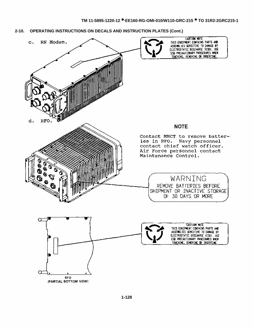
TM 11-5895-1220-12 •·EE160-RG-OMI-010/W110-GRC-215 • TO 31R2-2GRC215-1
2-10. OPERATING INSTRUCTIONS ON DECALS AND INSTRUCTION PLATES (Cont.)
1-128

TM 11-5895-1220-12 •·EE160-RG-OMI-010/W110-GRC-215 • TO 31R2-2GRC215-1
2-10. OPERATING INSTRUCTIONS ON DECALS AND INSTRUCTION PLATES (Cont.)
Change 2 2-129

TM 11-5895-1220-12 •·EE160-RG-OMI-010/W110-GRC-215 • TO 31R2-2GRC215-1
2-10. OPERATING INSTRUCTIONS ON DECALS AND INSTRUCTION PLATES (Cont.)
i. Remote Control Set.
j. TSEC/KY-65A. For operating instructions on decals and plates, refer to TM 11-5810-280-12 & P.
k. TSEC/KG-84A. For operating instructions on decals and plates, refer to TM 11-5810-308-12 & P.
2-130

TM 11-5895-1220-12 •·EE160-RG-OMI-010/W110-GRC-215 • TO 31R2-2GRC215-1
Section IV. OPERATION UNDER UNUSUAL CONDITIONS
2-11. OPERATION IN UNUSUAL WEATHER
a. Cold climates (Extreme cold causes cables and wires to become hard, brittle, and hard to handle).
WARNING
Do not allow flesh to touch equipment during periods of extreme cold. Bare flesh canfreeze and stick to the metal. Use gloves.
(1) Be careful when handling the cables and connecting them so that kinks and unnecessary loops will not resultin permanent damage.
(2) Make sure that the binding posts and the connectors are free of frost, snow, and ice.
(3) Replace the covers on the receptacles.
(4) Replace the connector cover as soon as a cable is removed.
(5) Do not drag or place an open connector in the snow.
b. Hot Climates (in hot, dry climates, connectors, receptacles, and binding posts are subject to damage from dustand dirt).
WARNING
Metal surfaces can become extremely hot when exposed to short periods in the sun.Test the surface first, before grasping, or use gloves.
(1) Replace the covers on the connectors and the receptacles.
(2) Do not place an open connector on the ground.
c. Warm, Damp Climates (in warm, damp climates, the equipment is subject to damage from moisture and fungi).Wipe all moisture and fungi from the equipment with a lint-free cloth (item 1, Appendix E).
2-12. EMERGENCY PROCEDURES
a. Emergency Stop. To turn the equipment off in an emergency, set the TT PS POWER switch (AC or DC asapplicable) to OFF.
Change 1 2-131

TM 11-5895-1220-12 •·EE160-RG-OMI-010/W110-GRC-215 • TO 31R2-2GRC215-1
2-12. EMERGENCY PROCEDURES (cont.) U
b. Recovery After Emergency Stop.
(1) Set all equipment power switches to OFF and perform normal power-on sequence procedure (para 2-7a).
(2) Initialize the Team Terminal (para 2-7b) and resume normal operation.
2-13. NUCLEAR, BIOLOGICAL, AND CHEMICAL (NBC) DECONTAMINATION PROCEDURES
Refer to Chemical, Biological, and Radiological (CBR) Decontamination, TM 3-220 (changes 1,2) for detaileddecontamination procedures for the materiel.
2-14. JAMMING AND ECM PROCEDURES
An indication of jamming is a constant noise being received on your assigned frequency, making it difficult orimpossible to maintain communications. To aid you in determining if you are the target of jamming, proceed as follows:
CAUTION
Do not transmit with the antenna disconnected or damage to the RT may occur.
a. Disconnect W202P1 from the DIP 50 ohm connector on the RT.
b. If noise continues, you may have a faulty RT; contact unit maintenance.
c. If noise goes away, you may be the target of jamming. Report suspected jamming as soon as possible.
2-15. LOADING TIME-OF-DAY
Refer to paragraph 3-11 if it is necessary to load TOD into your terminal.
Change 1 2-132

TM 11-5895-1220-12 •·EE160-RG-OMI-010/W110-GRC-215 • TO 31R2-2GRC215-1
CHAPTER 3
OPERATOR MAINTENANCE
SUBJECT PAGE
Lubrication Instructions ................................................................................................................................................ 3-1Troubleshooting Procedures ........................................................................................................................................ 3-1
Operator’s Troubleshooting Chart .................................................................................................................... 3-2Maintenance Procedures ............................................................................................................................................. 3-9
Repairs.............................................................................................................................................................. 3-9Replacement of Lamps, Fuses .............................................................................................................. 3-9, 3-10Charging of Battery Case/Charger, RCS ............................................................................................. 3-10, 3-11Cleaning. ................................................................................................................................................. 3-12
Testing .............................................................................................................................................................. 3-12Terminal, RT Off Line BIT .................................................................................................................... 3-12, 3-20
Timing Maintenance.......................................................................................................................................... 3-20
Section I. LUBRICATION INSTRUCTIONS
There are no lubrication requirements for this equipment.
Section II. TROUBLESHOOTING PROCEDURES
3-1. INTRODUCTION
Many problems occur which can be detected by visual inspection of the equipment. Repairs by the operator are limited tothose which require no test equipment or tools. The following are actions you can take that could solve problems quicklyand restore the Team Terminal to operation. In addition to these actions, a troubleshooting table is furnished to help youreturn the Team Terminal to operation.
a. Inspect your equipment for evidence of loose, damaged, missing or disconnected equipment. Replace faultyindicator lamps.
b. Make sure your power source is operating properly.
c. Use your natural senses. LOOK for damage. LISTEN for unusual noises. Electrical arcs may be heard aswell as seen. If an LRU feels extremely hot or odors of overheating materials are present, notify unit maintenance. Ifoperations permit, shut off LRUs which show evidence of overheating or arcing.
Change 1 3-1

TM 11-5895-1220-12 •·EE160-RG-OMI-010/W110-GRC-215 • TO 31R2-2GRC215-1
3-2. OPERATOR’S TROUBLESHOOTING CHART
The chart lists the common malfunctions which you may find during operation or maintenance of the Team Terminal.Perform the test or inspection. Take corrective actions listed in the table. Report all fault messages and any lighted failindicators to unit maintenance.
CAUTION
If switches (power ON/OFF/RESET) repeatedly trip or will not reset, contact unitmaintenance immediately. Repeatedly resetting switches may cause further damage andequipment failures.
MALFUNCTIONTEST OR INSPECTION
CORRECTIVE ACTION
1. TT PS WILL NOT POWER ON
Step 1. Observe for lighted POWER indicator on the TT PS.
Ensure DC (or AC) ON-OFF switch on TT PS is set to ON. Ensure input power cable is properly connectedto PWR IN connector on TT PS and that source power is normal.
Step 2. On TT PS, observe for lighted FAULT indicator and check to ensure OUTPUT VOLTAGE meter readsbetween +26.0 and +30.0 Vdc.
Report fault to unit maintenance.
2. I/O UNIT POWER ON INDICATOR WILL NOT LIGHT
Step 1. Check position of I/O Unit POWER switch.
Set I/O Unit POWER switch to ON.
Step 2. Ensure TT PS is powered on.
Perform TT PS WILL NOT POWER ON troubleshooting proced ure (malfunction no. 1).
Step 3. Check for faulty I/O Unit POWER ON indicator.
Replace I/O Unit POWER ON indicator.
Step 4. Check cable connections to I/O Unit.
Make proper cable connections. If problem persists, contact unit maintenance.
3-2

TM 11-5895-1220-12 •·EE160-RG-OMI-010/W110-GRC-215 • TO 31R2-2GRC215-1
3-2. OPERATOR’S TROUBLESHOOTING CHART (Cont.)
MALFUNCTIONTEST OR INSPECTION
CORRECTIVE ACTION
3. RT DISPLAY WILL NOT LIGHT
Step 1. Check position of RT power ON-OFF switch.
Set RT power ON-OFF switch to ON.
Step 2. Ensure TT PS is powered on.
Perform TT PS WILL NOT POWER ON troubleshooting procedure (malfunction no. 1).
Step 3. Check cable connections to RT and Vehicular Adapter.
Make proper cable connections.
Step 4. Check for blown fuse (F1 and/or F2) on Vehicular Adapter.
Replace blown fuse(s). If problem persists, contact unit maintenance.
Step 5. Check for burned out power indicator lamp on Vehicular Adapter.
Replace burned out lamps as necessary.
4. RN MODEM PWR ON INDICATOR WILL NOT LIGHT
Step 1. Check position of RN Modem PWR ON-OFF switch.
Set RN Modem PWR ON-OFF switch to ON.
Step 2. Ensure TT PS is powered on.
Perform TT PS WILL NOT POWER ON troubleshooting procedure (malfunction no. 1).
Step 3. Check for faulty RN Modem PWR ON indicator.
Replace RN Modem PWR ON indicator.
Step 4. Check cable connections to RN Modem.
Make proper cable connections. If problem persists, contact unit maintenance.
3-3

TM 11-5895-1220-12 •·EE160-RG-OMI-010/W110-GRC-215 • TO 31R2-2GRC215-1
3-2. OPERATOR’S TROUBLESHOOTING CHART (Cont.) ’
MALFUNCTIONTEST OR INSPECTION
CORRECTIVE ACTION
5. RFO EXT POWER INDICATOR WILL NOT LIGHT
Step 1. Check position of RFO RESET-OFF switch.
Set RFO RESET-OFF switch to RESET.
Step 2. Ensure TT PS is powered on.
Perform TT PS WILL NOT POWER ON troubleshooting procedure (malfunction no. 1).
Step 3. Check for faulty RFO EXT POWER indicator.
Replace RFO EXT POWER indicator.
Step 4. Check cable connections to RFO.
Make proper cable connections. If problem persists, contact unit maintenance.
6. POWER ON INDICATOR ON PA WILL NOT LIGHT
Step 1. Check position of RT power ON-OFF switch.
Set RT power ON-OFF switch to ON.
Step 2. Ensure TT PS is powered on.
Perform TT PS WILL NOT POWER ON troubleshooting procedure (malfunction no. 1).
Step 3. Check cable connections to PA, RT, and Vehicular Adapter.
Make proper cable connections. If problem persists, contact unit maintenance.
7. VEHICULAR ADAPTER POWER ON INDICATOR WILL NOT LIGHT
Step 1. Ensure TT PS is powered on.
Perform TT PS WILL NOT POWER ON troubleshooting procedure (malfunction no. 1).
3-4
TM 11-5895-1220-12 •·EE160-RG-OMI-010/W110-GRC-215 • TO 31R2-2GRC215-1
3-2. OPERATOR’S TROUBLESHOOTING CHART (Cont.)
MALFUNCTIONTEST OR INSPECTION
CORRECTIVE ACTION
Step 2. Check for faulty Vehicular Adapter power ON indicator.
Replace Vehicular Adapter power ON indicator.
Step 3. Check cable connections to Vehicular Adapter.
Make proper cable connections.
Step 4. Check for blown fuse (F1 and/or F2) on Vehicular Adapter.
Replace blown fuse(s). If problem persists, contact unit maintenance.
8. TSEC/KG-84A POWER INDICATOR WILL NOT LIGHT
Step 1. Check position of TSEC/KG-84A POWER ON-OFF switch.
Set TSEC/KG-84A POWER ON-OFF switch to ON.
Step 2. Ensure TT PS is powered on.
Perform TT PS WILL NOT POWER ON troubleshooting procedure (malfunction no. 1).
Step 3. Check for faulty TSEC/KG-84A POWER indicator.
Replace TSEC/KG-84A POWER indicator.
Step 4. Check cable connections to TSEC/KG-84A.
Make proper cable connections. If problem persists, contact unit maintenance.
9. TSEC/KY-65 WILL NOT POWER ON (METER ON TSEC/KY-65 INDICATES NO POWER)
Step 1. Check position of TSEC/KY-65 POWER switch.
Pull out and set TSEC/KY-65 POWER switch to ON.
Step 2. Ensure TT PS is powered on.
Perform TT PS WILL NOT POWER ON troubleshooting procedure (malfunction no. 1).
3-5

TM 11-5895-1220-12 •·EE160-RG-OMI-010/W110-GRC-215 • TO 31R2-2GRC215-1
3-2. OPERATOR’S TROUBLESHOOTING CHART (Cont.)
MALFUNCTIONTEST OR INSPECTION
CORRECTIVE ACTION
Step 3. Check cable connections to TSEC/KY-65.
Make proper cable connections. If problem persists, contact unit maintenance.
10. UNABLE TO ESTABLISH COMMUNICATIONS (NO FAULT MESSAGES)
Step 1. Check to ensure sidetone audio is heard from Handset.
Set RT power ON-OFF switch to OFF and then back to ON. If problem persists, try using Headset.
Step 2. Press VOICE MODE bezel key on the I/O Unit and check initialization parameters.
Enter corrections/changes to initialization parameters.
Step 3. Attempt to establish communications with another operator.
Increase transmit power and/or try relocating vehicle. If problem persists, attempt to establishcommunications using the NVIS Antenna. If problem still persists, contact unit maintenance.
11. MANPACK WILL NOT POWER-UP
Step 1. On RT, press key and observe for lighted display.
Set RT power ON-OFF switch to OFF and then to ON again. Ensure NORMAL-EXT. BAT. switch onBattery Case/Charger is set to NORMAL.
Step 2.Check to ensure Battery Case/Charger is securely fastened to RT.
Return RT and Battery Case/Charger to rack and recharge Battery Case/Charger (para 3-8c).
Step 3. With RT mounted in rack, press key and observe for lighted display.
Report problem to unit maintenance.
ENTTST
ENTTST
3-6

TM 11-5895-1220-12 •·EE160-RG-OMI-010/W110-GRC-215 • TO 31R2-2GRC215-1
3-2. OPERATOR’S TROUBLESHOOTING CHART (Cont.)
MALFUNCTIONTEST OR INSPECTION
CORRECTIVE ACTION
12. MANPACK COMMUNICATIONS IN SECURE VOICE MODE INOPERATIVE
Step 1. Check cable connections between Manpack and TSEC/KY-65.
Connect cables in accordance with paragraph 2-5b(2).
Step 2. Check for correct control settings on TSEC/KY-65.
Set SYNC MODE switch to HF. Adjust VOLUME control to a mid-range position. If problem persists, re-loadcrypto variables (para 2-7b, step 8).
Step 3. On TSEC/KY-65, set and hold INT BAT-AUDIO-EXT BAT switch to EXT BAT and observe meter readingfor +12.0 to +15.0 Vdc.
Report the problem to unit maintenance.
13. NO REMOTE VOICE OPERATION
Step 1. Check for proper control settings.
On R/E, ensure power ON-OFF switch is set to ON. On remote location, ensure R/T-OFF-TEL switch is setto R/T for radio communications or to TEL for telephone communications.
Step 2. Inspect Team Terminal remote control configuration.
Ensure configuration is correct and components are securely mounted (para 2-5a(5)). Clean binding postson remote location and R/E terminal. Ensure field wire is making good connection with binding posts. Ensure that earthground is connected to GRD post on remote location and that earth ground is connected to GRD post on R/E terminal.
Step 3. On ECCM Module, press key and observe for lighted display. T51
Recharge the remote location battery (para 3-8d). If problem persists, contact unit maintenance.
ENTTST
3-7

TM 11-5895-1220-12 •·EE160-RG-OMI-010/W110-GRC-215 • TO 31R2-2GRC215-1
3-2. OPERATOR’S TROUBLESHOOTING CHART (Cont.)
MALFUNCTIONTEST OR INSPECTION
CORRECTIVE ACTION
14. NO REMOTE DATA OPERATION
Step 1. Inspect Team Terminal configuration.
Ensure components are connected properly (para 2-5a(4)).
Step 2. Ensure Team Terminal is initialized for data operations.
Press I/O Unit DATA MODE bezel key and initialize Team Terminal for data mode.
3-8
TM 11-5895-1220-12 •·EE160-RG-OMI-010/W110-GRC-215 • TO 31R2-2GRC215-1
Section III. MAINTENANCE PROCEDURES
3-3. INTRODUCTION
Operator maintenance is limited to recharging the battery in the Remote Control Set, recharging the batteries inthe Battery Case/ Charger, replacing lamps and fuses and keeping the equipment clean.
3-4. INSPECTION
Inspect all components, assemblies and parts mounted in equipment rack to determine if the item is damaged orincomplete. If the item is damaged or incomplete, contact unit maintenance to replace/repair item.
3-5. CHECKS/ADJUSTMENTS/ALIGNMENT
Operator maintenance does not require any checks, adjustments, or alignment.
3-6. REMOVAL AND INSTALLATION
Operator maintenance does not require removal and installation of components.
3-7. DISASSEMBLY AND ASSEMBLY
Operator maintenance does not require disassembly and assembly of components.
3-8. REPAIRS
Operator repairs are limited to replacing lamps and fuses, recharging the batteries in the Battery Case/Charger,and recharging the battery in the Remote Control Set. Replacement of lamps in the PA, Remote Control Set, BatteryCase/Charger, and Vehicular Adapter (with the exception of the power ON indicator lamp) requires disassembly of theunit; notify MMCT.
a. Replace defective lamps. To replace a lamp:
(1) Turn off power.
(2) Turn the lamp holder counterclockwise; pull the lamp holder out of the receptacle.
(3) Pull the defective lamp out of the holder.
(4) Push a replacement lamp into the holder until it seats properly.
(5) Replace the lamp holder in the receptacle; turn it clockwise as far as it will turn.
3-9

TM 11-5895-1220-12 •·EE160-RG-OMI-010/W110-GRC-215 • TO 31R2-2GRC215-1
3-8. REPAIRS (Cont.)
(6) Slowly turn lense counterclockwise to open iris.
(7) Restore power.
b. Replace defective fuses. To replace a fuse:
(1) Ensure power is off
(2) Turn the fuse cap holder counterclockwise; pull it straight out of the receptacle.
(3) Remove defective fuse from receptacle and place a good fuse in the receptacle.
(4) Starting at the extreme counterclockwise position, snap the fuse into the receptacle; turn it as far clockwise asit will turn.
(5) Restore power.
c. Recharge Batteries in Battery Case/Charger. The Batteries in the Battery Case/Charger are rechargedautomatically when the Battery Case/Charger is installed in the Vehicular Adapter (vehicular configuration). If you areoperating in the Manpack configuration and need to recharge the batteries, proceed as follows:
(1) Disassemble the Manpack and mount the RT and Battery Case/Charger on the Vehicular Adapter. Refer toassembly and preparation for use procedures for manpack configuration (para 2-5b).
(2) Power up the Team Terminal (para 2-8a).
(3) On Battery Case/Charger, ensure NORMAL-EXT. BAT. switch is set to NORMAL. The EMERG. indicator onthe Battery Case/Charger and the MP-BAT CHG indicator on the Vehicular Adapter light to indicate a batteryrecharge is in process. These indicators go off when the battery recharge is complete.
3-10

TM 11-5895-1220-12 •·EE160-RG-OMI-010/W110-GRC-215 • TO 31R2-2GRC215-1
3-8. REPAIRS (Cont.)
d. Recharge Remote Location Battery
STEP1 On Vehicular Adapter,
loosen two thumbscrews and opencharger cable compartment lid.
NOTE
The R/E terminal does not need to be connected to remote location to recharge battery.
STEP2 Take charger cable out from its compartment and connect charger cable to PWR SUP. connector on the remote
location.
STEP3 Power-up the Team Terminal (para 2-8a). Observe that the Vehicular Adapter is providing a charge via a lighted
RCS - BAT CHG indicator on the Vehicular Adapter. Observe that the charge is in process via a lighted BAT CHGindicator on the Remote Location.
STEP4 Upon completion of battery charge (BAT CHG indicator on the remote location is not lit) disconnect the charger
cable from the remote location
STEP5 Store charger cable in its compartment, close lid, and tighten two thumbscrews.
3-11

TM 11-5895-1220-12 •·EE160-RG-OMI-010/W110-GRC-215 • TO 31R2-2GRC215-1
3-9. CLEANING
CAUTION
Never use scouring pads, steel wool, scouring powders, or harsh chemical agents, suchas lye solution when cleaning your equipment.
a. Use a dry, clean, lint-free cloth, (item 1, Appendix E) or brush (item 2, Appendix E) to remove dust or dirt. Ifneeded, moisten the cloth or brush with a mild solution of detergent (or soap) and water.
b. After cleaning, wipe dry with a clean cloth.
3-10. TESTING
This paragraph provides procedures for initiating terminal off-line BIT and RT off-line BIT. All equipment performscontinuous on-line background self-test. Faults are indicated via I/O Unit with both visual and audible alarm. If faults areindicated, Trouble Shoot IAW paragraph 3-2.
a. Terminal Off-Line Bit.
CAUTION
Do not activate bezel keys or screen touchpoints with any sharp item. Use of fingers,gloves or other soft and rounded item is required. The touchpoints are more sensitive toactivation with finger tips than the fleshy portion of the finger.
STEP1 With the Team Terminal powered-on, press the BIT bezel key on the D/K assembly to enable off-line BIT.
Change 1 3-12

TM 11-5895-1220-12 •·EE160-RG-OMI-010/W110-GRC-215 • TO 31R2-2GRC215-1
3-10. TESTING (Cont.)
TERMINAL OFF-LINE BIT (Cont.)
STEP2 The D/K assembly shows the warning message PERFORMING BIT WILL TAKE THE TERMINAL OUT OF THE
NET. ARE YOU SURE YOU WANT TO RUN BIT?
• If you are sure you want to run BIT, press the YES touch-point and then press NEXT MENU bezel key tocontinue. Proceed to step 3.
• If you do not want to run BIT, press the NO touchpoint and then press the NEXT MENU bezel key to
continue. The D/K assembly shows the last menu shown prior to pressing the BIT bezel key.
3-13

TM 11-5895-1220-12 •·EE160-RG-OMI-010/W110-GRC-215 • TO 31R2-2GRC215-1
3-10. TESTING (Cont.)
TERMINAL OFF-LINE BIT (Cont.)
STEP3 The D/K assembly shows the message DO YOU WISH TO PERFORM THE DISPLAY/KEYPAD TEST?. Press
the YES touchpoint to proceed to the DISPLAY/KEYPAD test. Press the NO touchpoint to proceed to whole terminal BIT.
• If YES was selected, proceed to STEP 4. • If NO was selected, proceed to STEP 8.
3-14

TM 11-5895-1220-12 •·EE160-RG-OMI-010/W110-GRC-215 • TO 31R2-2GRC215-1
3-10. TESTING (Cont.)
TERMINAL OFF-LINE BIT (Cont.)
NOTE
The next four steps provide instructions for you to run BIT on the D/K assembly via fourtest screens. If any fault conditions are observed, determine if you can continue operatingwith the fault; that is decide if the failed area of the display is critical to operation of the I/OUnit. Pressing the FAIL touchpoint will generate a system or I/O Unit fault.
STEP4 Observe the D/K assembly and check for a diagonal straight line. If the line is present, press PASS touchpoint. If
horizontal or vertical areas of the line are missing to the extent that operation of the I/O Unit cannot continue, press theFAIL touchpoint.
3-15

TM 11-5895-1220-12 •·EE160-RG-OMI-010/W110-GRC-215 • TO 31R2-2GRC215-1
3-10. TESTING (Cont.)
TERMINAL OFF-LINE BIT (Cont.)
STEP5 Observe the D/K assembly and check that the display is completely lighted. If lighted, press PASS touchpoint. If
areas of the D/K assembly are not lighted to the extent that operation of the I/O Unit cannot continue, press FAILtouchpoint.
3-16

TM 11-5895-1220-12 •·EE160-RG-OMI-010/W110-GRC-215 • TO 31R2-2GRC215-1
3-10. TESTING (Cont.)
TERMINAL OFF-LINE BIT (Cont.)
STEP6 The D/K assembly shows 66 lighted touchpoints. Press and release each touchpoint; check that each touchpoint
goes off as it is released. If any touchpoint fails to go off, depress any key on bezel to indicate test failure.
3-17

TM 11-5895-1220-12 •·EE160-RG-OMI-010/W110-GRC-215 • TO 31R2-2GRC215-1
3-10. TESTING (Cont.)
TERMINAL OFF-LINE BIT (Cont.)
STEP7 The D/K assembly shows 34 lighted squares around the edge of the display (one to correspond to each bezel
function switch). Select and depress all bezel function switches and observe that each corresponding touchpoint goes off.If all touchpoints do not go off, press FAIL touchpoint.
3-18

TM 11-5895-1220-12 •·EE160-RG-OMI-010/W110-GRC-215 • TO 31R2-2GRC215-1
3-10. TESTING (Cont.)
TERMINAL OFF-LINE BIT (Cont.)
STEP8 The D/K assembly shows the message BUILT IN TEST (BIT) RUNNING. The terminal completes the remaining
portion of off-line BIT. If a fault is detected, a fault message will be displayed on the status line (i.e. RFO FAULT). Reportfaults to unit maintenance. After BIT is successfully completed, the D/K assembly will show the message: TO BEGINSIGNING INTO THE NET, PRESS NEXT MENU.
THIS COMPLETES TERMINAL OFF-LINE BIT PROCEDURES
3-19

TM 11-5895-1220-12 •·EE160-RG-OMI-010/W110-GRC-215 • TO 31R2-2GRC215-1
3-10. TESTING (Cont.)
b. RT Off-line BIT.
3-11. TIMING MAINTENANCE
a. If the RFO has just been turned on, or if power is lost for more than 30 minutes (battery back-up time exceeded),Time-of-Day (TOD) must be loaded into the RFO. If MMCT is not available to load TOD, a RN Force Terminal, FAN ForceTerminal, RN Team Terminal, or another RN RFO can provide a source for loading TOD. The illustration below shows aTOD time transfer cable.
Change 1 3-20

TM 11-5895-1220-12 •·EE160-RG-OMI-010/W110-GRC-215 • TO 31R2-2GRC215-1
3-11. TIMING MAINTENANCE (Cont.)
b. Loading TOD - Force Terminal to Team Terminal RFO. Force Terminal must be situated so that the TOD timetransfer cable will reach from the Force Terminal signal entry panel to Team Terminal RFO.
STEP1 Switch RESET/OFF SWITCH 1 (under red cover on RFO) to RESET.
STEP2 Using the Time Transfer Cable, connect TIME TRANSFER jack 2 of Team Terminal RFO to SEP TIME
TRANSFER jack of Force Terminal.
STEP3 Press and release RCV TOD Switch 3 on RFO to receive TOD. SET CLOCK indicator 5 comes on.
STEP4 Press and release SEND TOD button 4 on Force Terminal SEP.
STEP5 If SET CLOCK indicator light 5 goes out TOD load is successful. If it is not out after 10 seconds, but
goes out after one minute, repeat steps 3-5. If SET CLOCK indicator still not out, refer RFO to maintenance.
STEP6 Disconnect TOD source. This completes load TOD procedures.
Change 1 3-21

TM 11-5895-1220-12 •·EE160-RG-OMI-010/W110-GRC-215 • TO 31R2-2GRC215-1
3-11. TIMING MAINTENANCE (Cont.)
c. Loading TOD - General. To load TOD from one RFO to another is basically the same procedure as loading TODForce Terminal to Team Terminal RFO. The difference is the connection is made between the TIME TRANSFER jackson both RFOS. The SEP TIME TRANSFER jack is not used. The connection is made with a TOD transfer cable. Whenthe connection has made, perform steps 3 through 6 of paragraph 3-11b.
Change 1 3-22

TM 11-5895-1220-12 •·EE160-RG-OMI-010/W110-GRC-215 • TO 31R2-2GRC215-1
CHAPTER 4
UNIT MAINTENANCE
SUBJECT PAGE
Repair Parts, Special Tools; Test, Measurement, and DiagnosticEquipment (TMDE); and Support Equipment ................................................................................................ 4-1
Service Upon Receipt................................................................................................................................................ 4-2Preliminary Servicing/Adjustments ................................................................................................................ 4-2
Hookup for Secure Data/Voice............................................................................................................. 4-3Hookup for Non-Secure Data............................................................................................................... 4-7
Unit Preventive Maintenance Checks and Services (PMCS).................................................................................... 4-7Troubleshooting......................................................................................................................................................... 4-10
Unit Troubleshooting Chart ............................................................................................................................ 4-11Unit Maintenance Procedures ................................................................................................................................... 4-33
Removal and Replacement of Major Components ................................................................................. 4-34 thru 4-69Cleaning......................................................................................................................................................... 4-70
Preparation for Storage or Shipment......................................................................................................................... 4-71
Section I. REPAIR PARTS, SPECIAL TOOLS; TEST, MEASUREMENT, AND DIAGNOSTICEQUIPMENT (TMDE); AND SUPPORT EQUIPMENT
4-1. COMMON TOOLS AND TEST EQUIPMENT
a. Army. For authorized common tools and test equipment, refer to Modified Table of Organization and Equipment(MTOE) applicable to your unit.
b. Navy. Navy personnel refer to applicable Tables of Allowances (TA).
c. Air Force. Air Force personnel refer to applicable Tables of Allowance (TA).
4-2. SPECIAL TOOLS, TMDE, AND SUPPORT EQUIPMENT
Special tools, TMDE, or support equipment and their purposes are listed in the Maintenance Allocation Chart,Appendix B.
4-3. REPAIR PARTS
Repair parts used during unit maintenance are listed and illustrated in the Repair Parts and Special Tools Listlocated in the TM 11-5895-1220-20P (Navy) EE160-RG-MIB-010/Wl10-GRC215 (Air Force) TO 31R2-2GRC215-4.
Change 2 4-1

TM 11-5895-1220-12 •·EE160-RG-OMI-010/W110-GRC-215 • TO 31R2-2GRC215-1
Section II. SERVICE UPON RECEIPT
4-4. SITE REQUIREMENTS
a. Antennas. Installation and use of antennas should not be near any tall metal objects or under heavy foliage.
b. Generator Set. If a generator set is used for ac power, locate the generator set approximately 75 feet away fromthe Team Terminal. This will reduce noise interference. Do not run power lines parallel to signal cables. Select an areawhere the ground is firm, dry, and has good drainage for ground installation.
4-5. SERVICE UPON RECEIPT OF MATERIEL
a. Inspect the equipment for damage incurred during shipment. If the equipment has been damaged, refer toparagraph 1-3 for instructions.
b. Check the equipment against the packing slip to see if the shipment is complete. Report all discrepancies inaccordance with the instructions of DA Pam 738-750.
c. Check to see whether the equipment has been modified.
4-6. INSTALLATION INSTRUCTIONS
A MK-2211/GRC-215 vehicle installation kit (installed by special installation team) provides the necessary materialto allow the Team Terminal to be installed in various vehicle types. The vehicle installation kit provides mounting for thefollowing:
• Equipment rack• Antenna base mount.• ATU mount.
4-7. PRELIMINARY SERVICING AND ADJUSTMENT OF EQUIPMENT
The following procedures are performed before newly installed equipment is put into operation.
a. Check Interconnections. An equipment hook-up chart is provided to check for proper interconnections. Theequipment hook-up chart provides cable connections necessary for local secure and nonsecure operation. An explanationof the chart is as follows:
(1) Cable Column - The cable column tells the cable number.
(2) Cable Connector Column - This column tells you the cable connector number for the cable listed in the cablecolumn. Hard-wired connections are identified with the abbreviation HW.
4-2

TM 11-5895-1220-12 •·EE160-RG-OMI-010/W110-GRC-215 • TO 31R2-2GRC215-1
4-7. PRELIMINARY SERVICING AND ADJUSTMENT OF EQUIPMENT (Cont.)
(3) Connected to Unit/Component Column - This column tells you to which unit or component each cableconnector is connected.
(4) Unit/Component Connector Column - This column tells you the unit or component connector number to whicheach cable must be connected.
b. Checks of Initial Control Settings. Ensure all equipment power switches are set to OFF before applying power.
c. Check Grounding. Ensure all ground straps for equipment mounts are connected and that the equipment rack isgrounded to the vehicle before applying power.
d. Check for firm seating and connection of all plug-in components.
CAUTION
Make all cable connections by hand. Do not use tools.
EQUIPMENT HOOK-UP FOR SECURE DATANOICE
Cable Cable Connect to Unit/ Unit/componentconnector component connector
W100 P1 TT PS PWR IN J1(Vehicle Lug A +12/24 Vdc Vehicle Powerpower) Lug B DC Common Vehicle Power
W101(115 Vac P1 TT PS PWR IN J1
power C Chassis ground 115 Vac sourcecable) E 115 Vac 115 Vac source
F Neutral 115 Vac source
W102 P1 TT PS PWR IN J1(230 Vac C Chassis ground 230 Vac source
power D 230 Vac 230 Vac sourcecable) F Neutral 230 Vac source
W103 HW Power Junction Unit W103P1 TSEC/KG-84A J1
W104 HW Power Junction Unit W104P1 Vehicular Adapter POWER
4-3

TM 11-5895-1220-12 •·EE160-RG-OMI-010/W110-GRC-215 • TO 31R2-2GRC215-1
4-7. PRELIMINARY SERVICING AND ADJUSTMENT OF EQUIPMENT (Cont.)
EQUIPMENT HOOK-UP FOR SECURE DATA/VOICE (Cont.)
Cable Cable Connect to Unit/ Unit/componentconnector component connector
W105 HW Power Junction Unit W105J2 ATU Interface Panel W111P1 Connects
J2 on ATUInterface
W106 HW Power Junction Unit W106P1 RFO PWR
W107 HW Power Junction Unit W107P1 PA J1
W108 HW Power Junction Unit W108P1 Z-AKE J1
W109 HW Power Junction Unit W109P1 RN Modem PWR IN J5
W110 HW Power Junction Unit Wl10P1 I/O Unit POWER J1
W111 P1 ATU Interface Panel J2P2 ATU J3
W112 P1 TT PS Mount FanHW Power Junction Unit W112
W201 P1 PA J4P2 ATU J2
W202 P1 R/E DIP 50P2 PA J3
W203 P1 RFO 10 MHZ OUTP2 CP1 (coaxial T) J1
W204 P1 RN Modem FREQ STAND J2P2 CP2 (coaxial T) J2
4-4

TM 11-5895-1220-12 •·EE160-RG-OMI-010/W110-GRC-215 • TO 31R2-2GRC215-1
4-7. PRELIMINARY SERVICING AND ADJUSTMENT OF EQUIPMENT (Cont.)
EQUIPMENT HOOK-UP FOR SECURE DATANOICE (Cont.)
Cable Cable Connect to Unit/ Unit/componentconnector component connector
W205 P1 Vehicular Adapter 10 MHZP2 CP2 (coaxial T) J1
W301 HW Control Junction Unit W301P1 RFO SYSTEM INTERFACE
W302A P1 Vehicular Adapter PA/ATUP2 PA J2
W302B P1 Vehicular Adapter PA/ATUJ1 ATU Interface Panel W303P1 Connects
J1 on ATUInterface
W303 P1 ATU Interface Panel J1P2 ATU J1
W304 P1 ECCM Module VEH ADPTR J2P2 Vehicular Adapter FAST SYNTH
W305 P1 I/O Unit KG-84 DATA J4P2 TSEC/KG-84A RED I/O J3
W306 P1 TSEC/KG-84A BLACK I/O J2P2 RN Modem KG-84 J4
W307 P1 ECCM Module SYNC J4P2 TSEC/KY-65A HANDSET
W308 P1 ECCM Module AUDIO J1P2 TSEC/KY-65A RADIO
W309 P1 I/O Unit Controller DISPLAY PWR/SIGAssembly J5
HW I/O Unit D/K assembly HW
W310 P1 I/O Unit CONTROL DATA J2HW Control Junction Unit W310
4-5

TM 11-5895-1220-12 •·EE160-RG-OMI-010/W110-GRC-215 • TO 31R2-2GRC215-1
4-7. PRELIMINARY SERVICING AND ADJUSTMENT OF EQUIPMENT (Cont.) 41,
EQUIPMENT HOOK-UP FOR SECURE DATANOICE (Cont.)
Cable Cable Connect to Unit/ Unit/componentconnector component connector
W311 P1 RN Modem CONTROL BUS J3HW Control Junction Unit W311
W312A P1 ECCM Module REMOTE J6HW Control Junction Unit W312
W312B P1 ECCM Module REMOTE J6P2 RN Modem RADIO J1l
W313 P1 I/O Unit Controller DISPLAY PWR/SIGJ5 AssemblyP2 W309 P1
(W313 used when remotingthe D/K assembly)
W3000 J2 KG-84A Nonsecure Bypass J2Assembly
J3 KG-84A Nonsecure Bypass J3Assembly
W1 Lug ATU ElLug Antenna mount HW
HAND- P1 ECCM Module KY J3SET
4-6

TM 11-5895-1220-12 •·EE160-RG-OMI-010/W110-GRC-215 • TO 31R2-2GRC215-1
4-7. PRELIMINARY SERVICING AND ADJUSTMENT OF EQUIPMENT (Cont.)
EQUIPMENT HOOK-UP FOR NONSECURE DATA
Equipment hook-up for nonsecure data is the same as for secure data except the TSEC/KG-84A is removed fromthe equipment rack (para 2-5a(2) and the TSEC/KG-84A cables are connected to the KG-84A nonsecure bypassassembly. The chart shows the cable connections for nonsecure data operation.
Cable Cable Connect to Unit/ Unit/componentconnector component connector
W103 P1 KG-84A nonsecure bypass assembly J1
W305 P2 KG-84A nonsecure bypass assembly J3
W306 P1 KG-84A nonsecure bypass assembly J2
EQUIPMENT HOOK-UP FOR NONSECURE VOICE
To configure for nonsecure voice operations, disconnect TSEC/KY-65A from the Team Terminal by disconnectingcables W307 and W308 from the ECCM Module. Connect Handset to AUDIO connector on ECCM Module.
NOTE
An alternate means of obtaining nonsecure voice operations is to set the TSEC/KY-65AMODE switch to PLAIN position.
Section III. UNIT PREVENTIVE MAINTENANCE CHECKS AND SERVICES (PMCS)
4-8. INTRODUCTION
Unit preventive maintenance procedures help maintain the equipment in a serviceable condition. They includeitems to be checked and procedures for checking them. The checks and services described in the PMCS table (para 4-9)outline inspections that are to be made at specific monthly (M) and quarterly (Q) intervals.
4-7

TM 11-5895-1220-12 •·EE160-RG-OMI-010/W110-GRC-215 • TO 31R2-2GRC215-1
4-8. INTRODUCTION (Cont.)
a. Routine Checks. The following items are not listed in the PMCS table and should be performed whenrequired:
• Checking for frayed cables.
• Tightening loose screws or nuts.
• Cleaning and dusting.
• Checking for broken or dented equipment rack.
b. Explanation of Columns.
(1) Item number column. This column is used as a source of item numbers for the TM Number Column onDA Form 2404, Equipment Inspection and Maintenance Worksheet, in recording results of PMCS.
(2) Interval column. This column specifies the frequency of the check, M for Monthly checks and Q forQuarterly checks.
(3) Item to be inspected column. This column lists the item to which the procedure is to be applied.
(4) Procedures column. This column describes the procedure by which the check is to be performed.
c. Preventive maintenance checks and services for the items listed below should be done in accordance withapplicable technical manuals:
• TSEC/KG-84A • TM 11-5810-308-12 & P
• TSEC/KY-65A • TM 11-5810-280-12 & P
d. Instructions for Reporting and Correcting Deficiencies. If your equipment does not perform as required, referto paragraph 4-10 for troubleshooting procedures. Report any malfunctions or failures on proper DA Form 2404, or referto DA Pam 738-750.
NOTE
If your equipment must be in operation all the time, only do items that can be checked andserviced with-out disturbing operation. Make the complete checks and services when theequipment can be shut down.
4-8

TM 11-5895-1220-12 •·EE160-RG-OMI-010/W110-GRC-215 • TO 31R2-2GRC215-1
4-9. UNIT PMCS TABLE
PREVENTIVE MAINTENANCE CHECKS AND SERVICES
Item Interval Item to be
No. M Q Inspected Procedure
1 • End item equipment. Inspect for completeness.Refer to COEI, appendix C.
2 • Publications. Check to see that all applicablepublications are complete,serviceable, and current(including all currentchanges). (Army only)
3 • Location of parts. Check to see that all componentsare mounted or stored inassigned places, exceptthose being used.
4 • Modification work Check to see if any MWOsorders. are needed for Team Terminal
components. Checkequipment to see if applicableMWOs have been applied andMWO number is stamped asrequired. Performmodification or requestmodification as applicable.
5 • Grounding system. Inspect all ground terminalconnections.a. Clean ground connections.b. Contact intermediategeneral support maintenanceif ground lead is cut,corroded, or broken.
6 • Binding posts on Clean binding posts with aManpack Remote soft bristle brush. CheckControl Set. to see that there is enough
tension to hold wires.
7 • Communications Initiate terminal off-lineequipment perform- BIT (para 3-10a). Ifance. abnormal operation is found
refer to troubleshootingprocedures (para 4-10).
4-9

TM 11-5895-1220-12 •·EE160-RG-OMI-010/W110-GRC-215 • TO 31R2-2GRC215-1
Section IV. TROUBLESHOOTING
4-10. INTRODUCTION
a. Unit level troubleshooting procedures for the Team Terminal are simplified by both on-line and off-line BIT.Terminal on-line BIT provides continuous monitoring of system operational status. Terminal off-line BIT is initiatedautomatically upon power-up or by pressing the BIT bezel key on the I/O Unit (para 3-10a). The BIT isolates faults toindividual components. Detected faults are indicated by the following:
• Fault messages shown on the D/K assembly (i.e. ATU FAULT, RFO FAULT, RN MODEM FAULT, etc.).
• Error codes displayed on the ECCM Module (i.e. 01, 02,).
• Lighted fault indicators on individual components.
b. Defects and corrective measures for items listed below are not in the troubleshooting chart. These are obviousand should be corrected as noted:
(1) Checking and replacement of power indicator lamps.
(2) Checking and resetting power ON-OFF switches.
(3) Checking and replacing fuses.
(4) Checking and replacing carrying harness if damaged or shows excessive wear.
NOTE
Check to be sure the operator has taken the necessary corrective actions beforeproceeding with unit troubleshooting. If corrective action consists of removal andreplacement of an item, it is important that recent events leading up to the fault indicationbe reported to next higher maintenance (i.e. fault messages, error codes, recent menuselections, current operating mode, frequency selection, net status etc.).
4-10

TM 11-5895-1220-12 •·EE160-RG-OMI-010/W110-GRC-215 • TO 31R2-2GRC215-1
4-11. UNIT TROUBLESHOOTING CHART
The troubleshooting chart lists common malfunctions which may be reported by the operator. Perform the test orinspection. Take the corrective action. Upon completion of corrective action and before returning the Team Terminal toservice, initiate terminal off-line BIT (para 3-10a) to verify system operational status. If BIT does not precisely identifyfailure and/or you cannot find the malfunction listed in the troubleshooting chart, inspect for faulty rack assembly,antennas, cables, and cable connections. If you are unable to locate or correct fault, contact intermediate general supportmaintenance.
MALFUNCTIONTEST OR INSPECTION
CORRECTIVE ACTION
1. LOSS OF POWER TO TERMINAL EQUIPMENT
Step 1. Perform terminal power-off sequence (para 2-8i). On TT PS, set DC ON-OFF switch (or AC ON-OFFswitch if auxiliary power is used) to ON. Observe that POWER indicator lights, that the FAIL indicator isoff and that the OUTPUT VOLTAGE meter reads between +26.0 and +30.0 Vdc.
If incorrect, proceed to step 2. If correct, but the problem persists, replace the TT PS (para 4-17i). If problem stillpersists, contact intermediate general support maintenance.
Step 2. Power off the TT PS and remove it part way (2 to 3 inches) from the power junction unit (para 4-17i).On TT PS, set DC ON-OFF switch (or AC ON-OFF switch) to ON. Observe that POWER indicatorlights, that the FAULT indicator is off, and that the OUTPUT VOLTAGE meter reads between +26.0 and+30.0 Vdc.
If correct, but fault persists, contact intermediate general support maintenance. If incorrect, try another powersource. If fault persists, replace the TT PS (para 4-17i).
Step 3. Initiate terminal off-line BIT (para 3-10a) to verify repair.
If fault persists, contact intermediate general support maintenance.
4-11

TM 11-5895-1220-12 •·EE160-RG-OMI-010/W110-GRC-215 • TO 31R2-2GRC215-1
4-11. UNIT TROUBLESHOOTING CHART (Cont.)
MALFUNCTIONTEST OR INSPECTION
CORRECTIVE ACTION
2. D/K ASSEMBLY SHOWS THE MESSAGE: ATU FAULT
NOTETerminal off-line BIT automatically tunes the ATU to three test frequencies. Mechanicalnoise can be heard from the ATU during tuning sequence. Troubleshooting proceduresmay instruct you to listen for this evidence of ATU tuning for fault isolation purposes.
Step 1. Initiate terminal off-line BIT (para 3-10a) and observe D/K assembly for repeat of fault message.
If fault message is repeated, proceed to step 2. If fault message is not repeated, return the Team Terminal toservice.
Step 2. Re-initiate terminal off-line BIT and check for mechanical tuning of the ATU.
If ATU tunes, proceed to step 3. If ATU does not tune, proceed to step 4.
Step 3. Re-initiate terminal off-line BIT and listen for a key tone in Handset.
If key tone is heard, proceed to step 5. If key tone is not heard, proceed to the troubleshooting procedure formalfunction no. 23 (ECCM MODULE SHOWS THE MESSAGE: FAILED).
Step 4. Disconnect W302P1 from PA/ATU connector on the Vehicular Adapter (this automatically enables thePA and ATU within the R/E and bypasses the external PA and ATU). Initiate off-line BIT on the RT(para 3-10b).
If RT off-line BIT passes, replace the ATU (para 4-17e). If RT off-line BIT fails, proceed to the troubleshootingprocedure for malfunction no. 23 (ECCM MODULE SHOWS THE MESSAGE: FAILED).
Step 5. Manually select several different frequencies (between =_ 2.0 and 29.9999 MHz) on the RT and attemptto establish communications with another operator.
4-12

TM 11-5895-1220-12 •·EE160-RG-OMI-010/W110-GRC-215 • TO 31R2-2GRC215-1
4-11. UNIT TROUBLESHOOTING CHART (Cont.)
MALFUNCTIONTEST OR INSPECTION
CORRECTIVE ACTION
If you can communicate on some frequencies, try relocating your vehicle and/or try reconfiguring theWhip Antenna (untie/tiedown antenna). If fault persists, use NVIS Antenna.
If you cannot communicate, replace Whip Antenna or try using NVIS Antenna. If fault persists,replace Antenna Cable W1. If fault still persists, contact intermediate general support maintenance.
Step 6. Initiate terminal off-line BIT (para 3-10a) to verify repair.
If fault persists, contact intermediate general support maintenance.
3. D/K ASSEMBLY SHOWS THE MESSAGE: BLK FAULT - A1A6, A1A7, A1PS1
Step 1. Initiate terminal off-line BIT (para 3-10a) and observe D/K assembly for repeat of fault message.
If fault message does not repeat, return the Team Terminal to service. If fault message repeats, setI/O Unit power ON-OFF switch to OFF and then to ON again. If fault persists, replace faulty I/O Unitsubassembly; refer to TM 11-5895-1322-24 (Navy) EE119-ND-MMI-010/Wll0-MX10819 (Air Force)TO 31R2- 2GRC215-32.
Step 2. Initiate terminal off-line BIT (para 3-10a) to verify repair.
If fault persists, replace the I/O Unit (para 4-17k). If replacement of the I/O Unit does not correct theproblem, contact intermediate general support maintenance.
4. D/K ASSEMBLY SHOWS THE MESSAGE: RED/BLK INTERFACE FAULT - A1A5, A1A6, AlAlA1
Step 1. Initiate terminal off-line BIT (para 3-10a) and observe D/K assembly for repeat of fault message.
If fault message does not repeat, return Team Terminal to service. If fault message repeats, set I/OUnit power ON-OFF switch to OFF and then to ON again. If fault persists, replace faulty I/O Unitsubassembly; refer to TM 11-5895-1322-24 (Navy) EE119-ND- MMI-010/Wl10-MX10819 (Air Force)TO 31R2-2GRC215-32.
4-13

TM 11-5895-1220-12 •·EE160-RG-OMI-010/W110-GRC-215 • TO 31R2-2GRC215-1
4-11. UNIT TROUBLESHOOTING CHART (Cont.)
MALFUNCTIONTEST OR INSPECTION
CORRECTIVE ACTION
Step 2. Initiate terminal off-line BIT (para 3-10a) to verify repair.
If fault persists, replace the I/O Unit (para 4-17k). If replacement of the I/O Unit does not correct theproblem, contact intermediate general support maintenance.
5. D/K ASSEMBLY SHOWS THE MESSAGE: DISPLAY/KEYPAD BIT FAULT - A2
Step 1. Initiate terminal off-line BIT (para 3-10a) and test the D/K assembly via the four test screens (para 3-10a, step 4 through step 7).
If the D/K assembly test screens pass, return the Team Terminal to service. If the D/K assembly testscreens fail, set I/O Unit power ON-OFF switch to OFF and then to ON again and repeat step 1. Iffault persists, record the fault and replace the D/K assembly; refer to TM 11-5895-1322-24 (Navy)EE119-ND-MMI-010/Wll0-MX10819 (Air Force) T031R2-2GRC215-32.
Step 2. Upon replacement of the D/K assembly, initiate terminal off-line BIT (para 3-10a) to verify repair.
If fault persists, replace the I/O Unit (para 4-17k).
6. D/K ASSEMBLY SHOWS THE MESSAGE: DISPLAY/KEYPAD INTERFACE FAULT - A1A5
Step 1. Initiate terminal off-line BIT (para 3-10a) and observe D/K assembly for repeat of fault message.
If fault message does not repeat, return Team Terminal to service. If fault message repeats, set I/OUnit power ON-OFF switch to OFF and then to ON again. If fault persists, replace faulty I/O Unitsubassembly; refer to TM 11-5895-1322-24 (Navy) EE119-ND- MMI-010/Wl10-MX10819 (Air Force)TO 31R2-2GRC215-32.
Step 2. Initiate terminal off-line BIT (para 3-10a) to verify repair.
If fault persists, replace the I/O Unit (para 4-17k). If replacement of the I/O Unit does not correct theproblem, contact intermediate general support maintenance.
4-14

TM 11-5895-1220-12 •·EE160-RG-OMI-010/W110-GRC-215 • TO 31R2-2GRC215-1
4-11. UNIT TROUBLESHOOTING CHART (Cont.)
MALFUNCTIONTEST OR INSPECTION
CORRECTIVE ACTION
7. D/K ASSEMBLY SHOWS THE MESSAGE: ECCM FAULT
Step 1. Initiate terminal off-line BIT (para 3-10a) and observe D/K assembly for repeat of fault message.
If fault message is repeated, proceed to step 2. If fault message is not repeated, return the TeamTerminal to service.
Step 2. Observe ECCM Module display for the message FAILED.
If the FAILED message is shown, proceed to the troubleshooting procedure for malfunction no. 23(ECCM MODULE SHOWS THE MESSAGE: FAILED). If the message is not shown, but problempersists, set RT power ON-OFF switch to OFF and then to ON again. Re-load ECCM ModuleTRANSEC variables (para 2-8b, step 5). If the problem still persists, remove RT from rack andreplace ECCM Module (para 4-17a).
Step 3. Initiate terminal off-line BIT (para 3-10a) to verify repair.
If problem persists, contact intermediate general support maintenance.
8. D/K ASSEMBLY SHOWS THE MESSAGE: TP/UP INTERFACE FAULT - A1A2, A1A3
Step 1. Initiate terminal off-line BIT (para 3-10a) and observe D/K assembly for repeat of fault message.
If fault message does not repeat, return the Team Terminal to service. If fault message repeats, setI/O Unit power ON-OFF switch to OFF and then to ON again. If fault persists, replace faulty I/O Unitsubassembly; refer to TM 11-5895-1322-24 (Navy) EE119-ND-MMI-010/Wll0-MX10819 (Air Force)TO 31R2- 2GRC215-32.
Step 2. Initiate terminal off-line BIT (para 3-10a) to verify repair.
If fault persists, replace the I/O Unit (para 4-17k). If replacement of the I/O Unit does not correct theproblem, contact intermediate general support maintenance.
4-15

TM 11-5895-1220-12 •·EE160-RG-OMI-010/W110-GRC-215 • TO 31R2-2GRC215-1
4-11. UNIT TROUBLESHOOTING CHART (Cont.)
MALFUNCTIONTEST OR INSPECTION
CORRECTIVE ACTION
9. D/K ASSEMBLY SHOWS THE MESSAGE: HIGH SPEED SYNTHESIZER FAULT
Step 1. Initiate terminal off-line BIT (para 3-10a) and observe D/K assembly for repeat of fault message.
If fault message is repeated, proceed to step 2. If fault message is not repeated, return the TeamTerminal to service.
Step 2. Observe Vehicular Adapter for a lighted FAULT indicator.
Replace Vehicular Adapter (para 4-17c) or contact intermediate general support maintenance toreplace the high speed synthesizer contained in the Vehicular Adapter.
Step 3. Initiate terminal off-line BIT (para 3-10a) and observe D/K assembly for repeat of fault message.
If fault message repeats, contact intermediate general support maintenance.
10. D/K ASSEMBLY SHOWS THE MESSAGE: RED INTERFACE CARD FAULT - A1A5
Step 1. Initiate terminal off-line BIT (para 3-10a) and observe D/K assembly for repeat of fault message.
If fault message does not repeat, return the Team Terminal to service. If fault message repeats, setI/O Unit power ON-OFF switch to OFF and then to ON again. If fault persists, replace faulty I/O Unitsubassembly; refer to TM 11-5895-1322-24 (Navy) EE119-ND-MMI-010/Wll0-MX10819 (Air Force)TO 31R2- 2GRC215-32.
Step 2. Initiate terminal off-line BIT (para 3-10a) to verify repair.
If fault persists, replace the I/O Unit (para 4-17k). If replacement of the I/O Unit does not correct theproblem, contact intermediate general support maintenance.
4-16

TM 11-5895-1220-12 •·EE160-RG-OMI-010/W110-GRC-215 • TO 31R2-2GRC215-1
4-11. UNIT TROUBLESHOOTING CHART (Cont.)
MALFUNCTIONTEST OR INSPECTION
CORRECTIVE ACTION
11. D/K ASSEMBLY SHOWS THE MESSAGE: KG-84A FAULT
Step 1. Ensure operator has loaded crypto variables. Initiate terminal off-line BIT (para 3-10a) and observeD/K assembly for repeat of fault message.
If fault message is repeated, replace TSEC/KG-84A (para 4-17g). If fault message is not repeated,return the Team Terminal to service.
Step 2. Upon replacement of TSEC/KG-84A, initiate terminal off-line BIT (para 3-10a) to verify repair.
If problem persists, contact intermediate general support maintenance.
12. D/K ASSEMBLY SHOWS THE MESSAGE: KG-84A INTERFACE FAULT - A1A5
Step 1. Initiate terminal off-line BIT (para 3-10a) and observe D/K assembly for repeat of fault message.
If fault message does not repeat, return the Team Terminal to service. If fault message repeats, setI/O Unit power ON-OFF switch to OFF and then to ON again. If fault persists, replace faulty I/O Unitsubassembly; refer to TM 11-5895-1322-24 (Navy) EEll19-ND-MMI-010/Wll0-MX10819 (Air Force)TO 31R2- 2GRC215-32.
Step 2. Initiate terminal off-line BIT (para 3-10a) to verify repair.
If fault persists, replace the I/O Unit (para 4-17k). If replacement of the I/O Unit does not correct theproblem, contact intermediate general support maintenance.
13. D/K ASSEMBLY SHOWS THE MESSAGE: NO RESPONSE FROM ECCM FAULT
Step 1. Ensure fill device is not connected to ECCM Module.
Disconnect fill device from ECCM Module.
4-17
TM 11-5895-1220-12 •·EE160-RG-OMI-010/W110-GRC-215 • TO 31R2-2GRC215-1
4-11. UNIT TROUBLESHOOTING CHART (Cont.)
MALFUNCTIONTEST OR INSPECTION
CORRECTIVE ACTION
Step 2. Initiate RT off-line BIT (para 3-10b).
If RT off-line BIT fails, proceed to the troubleshooting procedure for malfunction no. 23 (ECCMMODULE SHOWS THE MESSAGE: FAILED).
Step 3. Initiate terminal off-line BIT (para 3-10a) and check that ECCM Module and RN Modem accept thecommand to run their BIT (i.e. ECCM Module shows test displays and RN Modem BIT indicatorblinks).
If both units run BIT, remove the RT from rack and replace the ECCM Module (para 4-17a). If theECCM Module does not run BIT but the RN Modem does run BIT, proceed to step 4.
Step 4. Disconnect W311P2 from the CONTROL BUS connector on the RN Modem. Initiate terminal off-lineBIT (para 3-10a) and check that ECCM Module accepts the command to run BIT (ECCM Moduleshows test displays).
If the ECCM Module runs BIT, replace the RN Modem (para 4-17h). If the ECCM Module does notrun BIT, remove the RT from rack and replace the ECCM Module (para 4-17a).
Step 5. Initiate terminal off-line BIT (para 3-10a) to verify repair.
If fault persists, contact intermediate general support maintenance.
14. D/K ASSEMBLY SHOWS THE MESSAGE: NO 10KHZ AT ECCM FAULT
Step 1. Initiate RT off-line BIT (para 3-10b).
If RT off-line BIT fails, proceed to the troubleshooting procedure for malfunction no. 23 (ECCMMODULE SHOWS THE MESSAGE: FAILED).
Step 2. Initiate terminal off-line BIT (para 3-10a) and observe D/K assembly for repeat of fault message.
If fault message is not repeated, return the Team Terminal to service. If fault message is repeated,check for proper connections to the RT and to the Vehicular Adapter. If fault persists, remove the RTfrom the rack and replace the ECCM Module (para 4-17a).
4-18

TM 11-5895-1220-12 •·EE160-RG-OMI-010/W110-GRC-215 • TO 31R2-2GRC215-1
4-11. UNIT TROUBLESHOOTING CHART (Cont.)
MALFUNCTIONTEST OR INSPECTION
CORRECTIVE ACTION
Step 3. Initiate terminal off-line BIT (para 3-10a) to verify repair.
If fault persists, contact intermediate general support maintenance.
15. D/K ASSEMBLY SHOWS THE MESSAGE: PA FAULT
Step 1. Initiate terminal off-line BIT (para 3-10a) and observe D/K assembly for repeat of fault message.
If fault message is repeated, proceed to step 2. If fault message is not repeated, return the TeamTerminal to service.
Step 2. While observing the FAIL and the VSWR indicators on the PA, initiate terminal off-line BIT (para 3-10a).
If only the FAIL indicator on the PA lights, replace the PA (para 4-17d). If the VSWR indicator lightsfirst and then the FAIL indicator lights, proceed to step 3.
Step 3. Manually enter several other operating frequencies (between 2.0000 and 29.9999 MHz) and check tosee if the PA VSWR indicator lights and then the FAIL indicator lights.
If the fault continues when using other frequencies:
• Check for proper connections to PA, ATU, and Whip Antenna.• Try using the NVIS Antenna.• If fault persists, replace the PA and/or ATU (para 4-17d & e).
If the fault does not continue when using other frequencies:
• Check condition of Whip Antenna (check for damage, ensure all antenna sections are presentand securely connected).
• Try using the NVIS Antenna.Continue operation and report the fault to intermediate general support maintenance.
4-19

TM 11-5895-1220-12 •·EE160-RG-OMI-010/W110-GRC-215 • TO 31R2-2GRC215-1
4-11. UNIT TROUBLESHOOTING CHART (Cont.)
MALFUNCTIONTEST OR INSPECTION
CORRECTIVE ACTION
Step 4. After maintenance action, initiate terminal off-line BIT (para 3-10a) to verify repair.
If fault persists, contact intermediate general support maintenance.
16. D/K ASSEMBLY SHOWS THE MESSAGE: RECEIVER/EXCITER FAULT
Step 1. Observe ECCM Module display for the message: FAILED.
If the FAILED message is shown, proceed to step 2. If the FAILED message is not shown, replacethe RT (para 4-17a).
Step 2. Initiate RT off-line BIT (para 3-10b); check to see if the FAILED message reappears on the ECCMModule display.
If the FAILED message reappears, proceed to the troubleshooting procedure for malfunction no. 23(ECCM MODULE SHOWS THE MESSAGE: FAILED).
Step 3. Initiate terminal off-line BIT (para 3-10a) and observe D/K assembly for repeat of fault message.
If fault message repeats, contact intermediate general support maintenance.
17. D/K ASSEMBLY SHOWS THE MESSAGE: RECEIVER/EXCITER PA FAULT
Step 1. Observe ECCM Module display for the message: FAILED.
If the FAILED message is shown, proceed to step 2. If the FAILED message is not shown, replacethe RT (para 4-17a).
Step 2. Initiate RT off-line BIT (para 3-10b); check to see if the FAILED message reappears on the ECCMModule display.
If the FAILED message reappears, proceed to the troubleshooting procedure for malfunction no. 23(ECCM MODULE SHOWS THE MESSAGE: FAILED).
Step 3. Initiate terminal off-line BIT (para 3-10a) and observe D/K assembly for repeat of fault message.
If fault message repeats, contact intermediate general support maintenance.
4-20

TM 11-5895-1220-12 •·EE160-RG-OMI-010/W110-GRC-215 • TO 31R2-2GRC215-1
4-11. UNIT TROUBLESHOOTING CHART (Cont.)
MALFUNCTIONTEST OR INSPECTION
CORRECTIVE ACTION
18. D/K ASSEMBLY SHOWS THE MESSAGE: RFO FAULT
Step 1. Observe for lighted FAULT indicator on RFO.
Replace the RFO (para 4-17j).
Step 2. Initiate terminal off-line BIT (para 3-10a) and observe D/K assembly for repeat of fault message.
If fault message repeats, contact intermediate general support maintenance.
19. D/K ASSEMBLY SHOWS THE MESSAGE: RN MODEM FAULT
Step 1. Initiate terminal off-line BIT (para 3-10a) and observe D/K assembly for repeat of fault message.
If fault message is repeated, proceed to step 2. If fault message is not repeated, return the TeamTerminal to service.
Step 2. On the RN Modem, disconnect all cables except W109 and W204. Press the BIT initiate switch andobserve BIT fault indicator.
If BIT fault indicator does not light, contact intermediate general support maintenance. If BIT faultindicator lights, fault isolate and replace faulty RN Modem subassembly; refer to TM 11-5895-1307-24(Navy) EE163-HK-MMI-O10/WllO-MD1204 (Air Force) TO 31R2-4-585-2.
Step 3. On the RN Modem, press the BIT initiate switch and observe BIT fault indicator to verify repair.
If the BIT fault indicator still lights, replace the RN Modem (para 4-17h).
Step 4. Initiate terminal off-line BIT (para 3-10a) and observe D/K assembly for repeat of fault message.
If fault message repeats, contact intermediate general support maintenance.
4-21

TM 11-5895-1220-12 •·EE160-RG-OMI-010/W110-GRC-215 • TO 31R2-2GRC215-1
4-11. UNIT TROUBLESHOOTING CHART (Cont.)
MALFUNCTIONTEST OR INSPECTION
CORRECTIVE ACTION
20. D/K ASSEMBLY SHOWS THE MESSAGE: TP FIFO BIT FAULT - A1A3
Step 1. Initiate terminal off-line BIT (para 3-10a) and observe D/K assembly for repeat of fault message.
If fault message does not repeat, return Team Terminal to service. If fault message repeats, set I/OUnit power ON-OFF switch to OFF and then to ON again. If fault persists, replace faulty I/O Unitsubassembly; refer to TM 11-5895-1322-24 (Navy) EE119-ND- MMI-010/Wl10-MX10819 (Air Force)TO 31R2-2GRC215-32.
Step 2. Initiate terminal off-line BIT (para 3-10a) to verify repair.
If fault persists, replace the I/O Unit (para 4-17k). If replacement of the I/O Unit does not correct theproblem, contact intermediate general support maintenance.
‘
Step 1. Initiate terminal off-line BIT (para 3-10a) and observe D/K assembly for repeat of fault message.
If fault message does not repeat, return Team Terminal to service. If fault message repeats, set I/OUnit power ON-OFF switch to OFF and then to ON again. If fault persists, replace faulty I/O Unitsubassembly; refer to TM 11-5895-1322-24 (Navy) EE119-ND- MMI-010/Wl10-MX10819 (Air Force)TO 31R2-2GRC215-32.
Step 2. Initiate terminal off-line BIT (para 3-10a) to verify repair.
If fault persists, replace the I/O Unit (para 4-17k). If replacement of the I/O Unit does not correct theproblem, contact intermediate general support maintenance.
22. D/K ASSEMBLY SHOWS THE MESSAGE: UP FIFO BIT FAULT - A1A2
Step 1. Initiate terminal off-line BIT (para 3-10a) and observe D/K assembly for repeat of fault message.
4-22

TM 11-5895-1220-12 •·EE160-RG-OMI-010/W110-GRC-215 • TO 31R2-2GRC215-1
4-11. UNIT TROUBLESHOOTING CHART (Cont.)
MALFUNCTIONTEST OR INSPECTION
CORRECTIVE ACTION
If fault message does not repeat, return Team Terminal to service. If fault message repeats, set I/OUnit power ON-OFF switch to OFF and then to ON again. If fault persists, replace faulty I/O Unit subassembly; refer to TM11-5895-1322-24 (Navy) EE119-ND- MMI-010/Wl10-MX10819 (Air Force) TO 31R2-2GRC215-32.
Step 2. Initiate terminal off-line BIT (para 3-10a) to verify repair.
If fault persists, replace the I/O Unit (para 4-17k). If replacement of the I/O Unit does not correct theproblem, contact intermediate general support maintenance.
23. ECCM MODULE SHOWS THE MESSAGE: FAILED
Step 1. On ECCM Module, press key and observe display for an error code.
If errorcode is: Do the following:
01 Perform troubleshooting procedure for malfunction no. 15.
02 Perform troubleshooting procedure for malfunction no. 2.
03 through 09 Not used in this application.
10 Check for proper cable connections between RN Modem and RT.Ensure RN Modem is ON and passes BIT.
11 ECCM Module does not contain TRANSEC variables. Load TRANSECvariables (para 2-8b, step 5).
12 ECCM Module has not received a valid TOD. Re-initialize terminal(para 2-8b).
4-23
ENTTST

TM 11-5895-1220-12 •·EE160-RG-OMI-010/W110-GRC-215 • TO 31R2-2GRC215-1
4-11. UNIT TROUBLESHOOTING CHART (Cont.)
MALFUNCTIONTEST OR INSPECTION
CORRECTIVE ACTION
If errorcode is: Do the following:
13 RT only allowing voice modes. Initialize terminal for data mode (para 2-8b).
14 Remove fill device from FILL connector on ECCM Module.
15 and 16 Not displayed.
17 Check for proper cable connections between RN Modem, RT, and Vehicular Adapter. Initiate BIT on RT (para 3-10b). If problem persists, replace the RN Modem (para 4-17h). If problem still persists, replace the Vehicular Adapter (para 4-17c).
18 and 19 Not used in this application.
20 through 49 On RT, cycle power OFF/ON. If RT passes BIT, re-initialize terminal.If RT fails BIT, record error code, remove RT from rack and replace ECCM Module (para 4-17a).
50 Record error code. Replace RT (para 4-17a). Initiate BIT on RT (para3-10b). If problem persists replace ECCM (para 4-17a).
51 Replace the Vehicular Adapter (para 4-17c) or contact intermediategeneral support maintenance to replace the high speed synthesizer.
52 through 55 On RT, cycle power OFF/ON. If RT passes BIT, re-initialize terminal.If RT fails BIT, record error code, remove RT from rack and replaceECCM Module (para 4-17a).
4-24

TM 11-5895-1220-12 •·EE160-RG-OMI-010/W110-GRC-215 • TO 31R2-2GRC215-1
4-11. UNIT TROUBLESHOOTING CHART (Cont.)
MALFUNCTIONTEST OR INSPECTION
CORRECTIVE ACTION
If errorcode is: Do the following:
56 Record error code. Remove RT from rack and replace ECCM Module(para 4-17a). Initiate BIT on RT (para 3-lo0b). If problem persists,replace the RT.
57 Record error code and replace the RT (para 4-17a).
58 through 69 Not used in this application.
70 Perform RT off-line BIT (para 3-10b). If FAILED message is notrepeated, return the RT to service. If the FAILED message is repeated,press the ENT key and observe ECCM Module display for an error code.
• If error code 70 is repeated, record the error code and the presentoperating frequency (if possible) and replace the RT (para 4-17a).
• If any other error code is shown, perform the applicable correctiveaction.
71 Perform terminal off-line BIT (para 3-10) to verify operation of the I/OUnit.
• If BIT detects an I/O Unit fault, isolate and replace faulty I/O Unitsubassembly; refer to TM 11- 5895-1322-24 (Navy) EEll19- ND-MMI-010/WllO-MX10819 (Air Force) TO 31R2-2GRC215-32.
• If BIT does not detect fault, replace the I/O Unit (para 4-17k). Ifproblem persists, replace the RFO (para 4-17j).
4-25

TM 11-5895-1220-12 •·EE160-RG-OMI-010/W110-GRC-215 • TO 31R2-2GRC215-1
4-11. UNIT TROUBLESHOOTING CHART (Cont.)
MALFUNCTIONTEST OR INSPECTION
CORRECTIVE ACTION
If errorcode is: Do the following:
• If problem persists further, replace ECCM (para 4-17a).
72 Perform RT off-line BIT (para 3-10b). If FAILED message is notrepeated, return the RT to service. If the FAILED message is repeated,press the ENT key and observe ECCM Module display for an error code.
• If error code 72 is repeated, rerecord the error code and the presentoperating frequency (if possible) and replace the RT (para 4-17a).
• If any other error code is shown, perform the applicable correctiveaction.
73 and 74 Perform terminal off-line BIT (para 3-10) to verify operation of the I/OUnit.
• If BIT detects an I/O Unit fault, isolate and replace faulty I/O Unitsubassembly; refer to TM 11-5895-1322-24 (Navy) EE119- ND-MMI-010/Wl10-MX10819 (Air Force) TO 31R2-2GRC215-32.
• If BIT does not detect fault, replace the I/O Unit (para 4-17k).
• If problem persists, replace ECCM (para 4-17a).
75 and 76 Not used in this application
77 Perform BIT on ECCM, para 3-10b. If problem persists, replace ECCM(para 4-17a).
4-26

TM 11-5895-1220-12 •·EE160-RG-OMI-010/W110-GRC-215 • TO 31R2-2GRC215-1
4-11. UNIT TROUBLESHOOTING CHART (Cont.)
MALFUNCTIONTEST OR INSPECTION
CORRECTIVE ACTION
If errorcode is: Do the following:
78 and 79 Not used in this application.
Step 2. Initiate RT off-line BIT (para 3-10b).
If BIT passes, return the Team Terminal to service.
If BIT failed, press key on ECCM Module, record fault code and contact intermediate general
support maintenance.
24. D/K ASSEMBLY APPEARS TO BE LOCKED-UP (WILL NOT ADVANCE TO NEXT MENU); NO FAULTMESSAGES SHOWN ON THE D/K ASSEMBLY
Step 1. On the I/O Unit, press and release the BIT-RESET switch and attempt to re-initialize Team Terminal(para 2-7b).
If fault continues, replace the I/O Unit (para 4-17k) and proceed to step 2. If fault does not continue,return the Team Terminal to service.
Step 2. Initiate terminal off-line BIT (para 3-10a) to verify repair.
If problem persists, contact intermediate general support maintenance.
25. THE D/K ASSEMBLY DOES NOT DISPLAY CHARACTERS PROPERLY OR BEZEL KEYS DO NOTFUNCTION PROPERLY; NO FAULT MESSAGES SHOWN ON THE D/K ASSEMBLY
Step 1. Initiate terminal off-line BIT (para 3-10a) and test the D/K assembly via the four test screens.
If the D/K assembly passes the test, return Team Terminal to service. If the D/K assembly fails thetest, note the fault and replace the D/K assembly; refer to TM 11-5895-1322-24 (Navy) EEll19-ND-MMI-010/WllO-MX10819 (Air Force) TO 31R2-2GRC215-32.
Step 2. Upon replacement of the D/K assembly, initiate terminal off-line BIT (para 3-10a) to verify repair.
If fault persists, replace the I/O Unit (para 4-17k).
4-27
ENTTST

TM 11-5895-1220-12 •·EE160-RG-OMI-010/W110-GRC-215 • TO 31R2-2GRC215-1
4-11. UNIT TROUBLESHOOTING CHART (Cont.)
MALFUNCTIONTEST OR INSPECTION
CORRECTIVE ACTION
26. CANNOT RECEIVE OR TRANSMIT IN SECURE DATA MODE (VOICE MODE NORMAL AND NO FAULTMESSAGES SHOWN ON THE D/K ASSEMBLY)
Step 1. Ensure the Team Terminal has been properly initialized for the secure data mode (para 2-8b). Initiateterminal off-line BIT (para 3-10a) and observe the D/K assembly for any fault messages.
If the D/K assembly shows a fault message, proceed to the applicable troubleshooting procedure inthis table. If no fault messages are shown, proceed to step 2.
Step 2. Bypass the TSEC/KG-84A using the KG-84 nonsecure bypass assembly (para 2-5a) and initialize theTeam Terminal for the nonsecure data mode. Attempt to establish communications with anotheroperator (receiving terminal must be in nonsecure mode).
If you are able to establish nonsecure data communications, replace the TSEC/KG-84A (para 4-17g)and proceed to step 3. If you cannot establish nonsecure data communications, proceed to thetroubleshooting procedure for malfunction no.
Step 3. Upon replacement of TSEC/KG-84A, initialize the Team Terminal for the secure data mode andattempt to establish communications with another operator. If problem persists, contact intermediategeneral support maintenance.
27. CANNOT RECEIVE OR TRANSMIT IN NONSECURE DATA MODE (VOICE MODE NORMAL AND NO FAULTMESSAGES SHOWN ON THE D/K ASSEMBLY)
Step 1. Ensure the Team Terminal has been properly initialized for the nonsecure data mode (para 2-8b).Initiate terminal off-line BIT (para 3-10a) and observe the D/K assembly for any fault messages.
If the D/K assembly shows a fault message, proceed to the applicable troubleshooting procedure inthis table. If no fault messages are shown, proceed to step 2.
Step 2. Check for faulty RN Modem.
Replace RN Modem (para 4-17h). If problem persists, replace
4-28

TM 11-5895-1220-12 •·EE160-RG-OMI-010/W110-GRC-215 • TO 31R2-2GRC215-1
4-11. UNIT TROUBLESHOOTING CHART (Cont.)
MALFUNCTIONTEST OR INSPECTION
CORRECTIVE ACTION
the I/O Unit (para 4-17k). If replacement of the I/O Unit does not correct the problem, contactintermediate general support maintenance.
28. CANNOT RECEIVE OR TRANSMIT IN SECURE VOICE MODE (NO FAULT MESSAGES SHOWN ON THE D/KASSEMBLY)
Step 1. Ensure the Team Terminal has been properly initialized for the secure voice mode (para 2-8b).Initiate terminal off-line BIT (para 3-10a) and observe the D/K assembly for any fault messages.
If the D/K assembly shows a fault message, proceed to the applicable troubleshooting procedure inthis chart.
Step 2. Disconnect W308P1 from RT and connect Handset to AUDIO connector of RT. Attempt to establishcommunications with another operator.
If you are able to establish nonsecure voice communications, replace faulty TSEC/KY-65 or Z-AKE asapplicable (refer to TM 11-5810-280-12 & P for maintenance procedures). If problem persists,contact intermediate general support maintenance.
If you are unable to establish nonsecure voice communications, proceed to the troubleshootingprocedure for malfunction no. 29 (CANNOT RECEIVE OR TRANSMIT IN NONSECURE VOICEMODE).
29. CANNOT RECEIVE OR TRANSMIT IN NONSECURE VOICE MODE (NO FAULT MESSAGES SHOWN ON THED/K ASSEMBLY)
Step 1. Ensure the Team Terminal has been properly initialized for the nonsecure voice mode (para 2-8b).Initiate terminal off-line BIT (para 3-10a) and observe the D/K assembly for any fault messages.
If the D/K assembly shows a fault message, proceed to the applicable troubleshooting procedure inthis table. If no fault messages are shown, proceed to step 2.
4-29

TM 11-5895-1220-12 •·EE160-RG-OMI-010/W110-GRC-215 • TO 31R2-2GRC215-1
4-11. UNIT TROUBLESHOOTING CHART (Cont.)
MALFUNCTIONTEST OR INSPECTION
CORRECTIVE ACTION
Step 2. Check for faulty Handset (or Headset if used).
Replace Handset (or Headset if used). If problem persists, contact intermediate general supportmaintenance.
30. UNABLE TO POWER-UP MANPACK
Step 1. Check to ensure that Battery Case/Charger is securely mounted to RT and check for proper controlsettings.
Tighten clip latches on Battery Case/Charger. On RT, set power ON-OFF switch to ON. On BatteryCase/ Charger, set NORMAL-EXT. BAT. switch to NORMAL.
Step 2. Check for faulty Battery Case/Charger; BAT CHG LED on front of Vehicular Adapter should be lit toindicate battery charging.
Replace Battery Case/Charger; refer to Manpack disassembly procedures (para 2-5b(l)). Check BATCHG LED, if not lit replace Vehicular Adapter (para 4-17c).
31. MANPACK COMMUNICATIONS IN SECURE VOICE MODE INOPERATIVE
Step 1. Check cable connections between Manpack and TSEC/KY-65.
Connect cables in accordance with paragraph 2-5b(2).
Step 2. Check for correct control settings on TSEC/KY-65.
Set SYNC MODE switch to HF. Adjust VOLUME control to a mid-range position. If fault persists, re-load crypto variables (para 2-8b. step 4).
Step 3. On TSEC/KY-65, set and hold INT BAT-AUDIO-EXT BAT to EXT BAT and observe meter reading for+12.0 to +13.5 Vdc.
Replace TSEC/KY-65 (para 2-5b(2)). If fault persists, contact intermediate general supportmaintenance.
32. CANNOT RECEIVE OR TRANSMIT IN MANPACK SECURE OR NONSECURE MODE (NO FAULT CODESHOWN ON RT DISPLAY)
Step 1. Check for faulty RT.
Remove RT from rack and replace ECCM Module (para 2-5b(1)). If problem persists, replace the RT.
4-30

TM 11-5895-1220-12 •·EE160-RG-OMI-010/W110-GRC-215 • TO 31R2-2GRC215-1
4-11. UNIT TROUBLESHOOTING CHART (Cont.)
MALFUNCTIONTEST OR INSPECTION
CORRECTIVE ACTION
Step 2. Check for faulty Battery Case/Charger; BAT CHG LED on front of Vehicular Adapter should be lit toindicate battery charging.
Replace Battery Case/Charger; refer to Manpack disassembly procedures (para 2-5b(l)). Check BATCHG LED, if not lit replace Vehicular Adapter (para 4-17c).
Step 3. Check for faulty Handset.
Replace Handset. If problem persists, replace Manpack Whip Antenna.
33. UNABLE TO OPERATE IN REMOTE VOICE CONFIGURATION
Step 1. Observe ECCM Module display for the message: FAILED.
Refer to the troubleshooting procedure for malfunction no. 23 (ECCM MODULE SHOWS THEMESSAGE: FAILED).
Step 2. Observe for lighted BITE indicator on R/E terminal. LED lit indicates a malfunction.
Refer to assembly and preparation for use procedures for remote voice operations (para 2-5a(5)) andreplace R/E. If problem persists, replace Remote Control Set.
Step 3. Inspect equipment hook-up to ensure Team Terminal is properly configured for remote voiceoperations (para 2-5a(5)).
Configure Team Terminal for remote voice operations. Check for proper cable connections. If faultpersists, contact intermediate general support maintenance.
34. UNABLE TO OPERATE IN REMOTE DATA CONFIGURATION
Step 1. Initiate terminal off-line BIT (para 3-10a) and observe D/K assembly for fault message.
Refer to applicable troubleshooting procedure and perform corrective action.
4-31

TM 11-5895-1220-12 •·EE160-RG-OMI-010/W110-GRC-215 • TO 31R2-2GRC215-1
4-11. UNIT TROUBLESHOOTING CHART (Cont.)
MALFUNCTIONTEST OR INSPECTION
CORRECTIVE ACTION
Step 2. Inspect equipment hook-up to ensure Team Terminal is properly configured for remote dataoperations (para 2-5a(4)).
Configure Team Terminal for remote data operations. Tighten cable connections.
Step 3. Re-initialize Team Terminal for data mode. Replace remote cable. If problem persists, contactintermediate general support maintenance.
35. D/K ASSEMBLY SHOWS THE MESSAGE: POWER SUPPLY FAULT - A1PS1
Step 1. Initiate terminal off-line BIT (para 3-l0a) and observe D/K assembly for fault message. If faultmessage does not repeat, return the Team Terminal to service.
If fault message repeats, set I/O Unit power ON-OFF switch to OFF and then to ON again. If faultpersists, replace faulty I/O Unit subassembly; refer to TM 11-5895-1322-24 (Navy) EEll19-ND-MMI-010/Wll0-MX10819 (Air Force) TO 31R2-2GRC215-32.
Step 2. Initiate terminal off-line BIT (para 3-10a) to verify repair.
If fault persists, replace the I/O Unit (para 4-17k). If replacement of the I/O Unit does not correct theproblem, contact intermediate general support maintenance.
36. DURING NVIS OPERATION D/K ASSEMBLY SHOWS THE MESSAGE: ATU FAULT; OR ATU FAILS TOTUNE; OR HIGH VSWR INDICATED DURING NVIS OR AFTER RETURN TO NORMAL WHIP OPERATION.
Step 1. Disconnect RF input cable from PA J3. Check Antenna Matching Capacitor attached to El terminal ofATU. For NVIS operation the W1 rf cable should be connected to the tip-end of the capacitor. ForAS-3809/G whip operation, W1 should be connected to the side of the capacitor. Ensure connectionis correct, and screw is tight. If in NVIS mode, and ATU will not tune, or high VSWR is indicated,replace capacitor.
Step 2. Re-connect RF input cable to PA J3. Initiate terminal off-line BIT (para 3-10a) to verify repair. If faultpersists, replace the ATU (para 4-17e). If replacement of the ATU does not correct the problem,contact intermediate general support maintenance.
Change 1 4-32

TM 11-5895-1220-12 •·EE160-RG-OMI-010/W110-GRC-215 • TO 31R2-2GRC215-1
Section V. UNIT MAINTENANCE PROCEDURES
4-12. INTRODUCTION
This section contains maintenance procedures which are the responsibility of unit maintenance as authorized bythe Maintenance Allocation Chart (MAC); refer to appendix B.
4-13. GROUND HANDLING
a. Equipment data, including component weights and dimension, are provided in paragraph 1-13. Somecomponent weight limits are greater than one person lift. When removing/installing components, observe personnel liftwarnings marked on equipment labels and stated in this manual.
b. This equipment contains electrostatic sensitive devices (ESD) items. Refer to paragraph 4-16 for guidelinesto handle, transport, and store ESD items.
c. Prior to removing or installing a component, ensure that power to the component has been turned off.Cables disconnected with voltage present may arc or short. This can produce damage to the equipment.
4-14. OPERATIONAL CHECK
To check the operational condition of the Team Terminal, perform terminal off-line BIT (para 3-10a).
4-15. INSPECTION OF INSTALLED ITEMS
Inspect all components, assemblies and parts mounted in equipment rack to determine if the item is damaged orincomplete to the extent that it should be replaced/repaired.
4-16. ELECTROSTATIC DISCHARGE HANDLING PROCEDURES
All Team Terminal equipment contains certain static-sensitive solid state devices which are subject to damagefrom electrostatic discharge. Effective control of electrostatic discharge is maintained only through continuous strictobservance of the following maintenance procedures.
a. Any maintenance requiring disassembly of the equipment must be performed at an approved work station.The work station must include a grounded surface and grounded wrist strap in accordance with DOD-HDBK-263.
b. All maintenance personnel must have completed training in the handling of static-sensitive devices beforeworking on this equipment. Maintenance personnel must wear the grounded wrist strap and be at an approved workstation when performing maintenance.
4-33

TM 11-5895-1220-12 •·EE160-RG-OMI-010/W110-GRC-215 • TO 31R2-2GRC215-1
4-16. ELECTROSTATIC DISCHARGE HANDLING PROCEDURES (Cont.)
c. The static sensitive subassemblies or circuit cards must be stored in approved electrostatic free materialwhen not installed in the equipment.
4-17. REMOVAL AND REPLACEMENT OF MAJOR COMPONENTS
a. RT.
REMOVAL AND REPLACEMENT OF RT
REMOVAL
STEP1 Perform terminal power-off sequence (para 2-8i).
STEP2 Disconnect cable plugs W202P1,
W304P1, W308P1, W307P1, W312P1, andhandset (if required) from RT frontpanel. Place connector covers on connectors.
STEP3 On Vehicular Adapter, loosen and
free 4 clip latches. Remove RT fromVehicular Adapter by lifting up and forward.
4-344-34

TM 11-5895-1220-12 •·EE160-RG-OMI-010/W110-GRC-215 • TO 31R2-2GRC215-1
4-17. REMOVAL AND REPLACEMENT OF MAJOR COMPONENTS (Cont.)
REMOVAL AND REPLACEMENT OF RT (Cont.)
REMOVAL (Cont.)
STEP4 If maintenance action
requires removal of ECCM Moduleor R/E, disassemble the RT byloosening 7 spring latches(2 located on top and bottom,2 on left-hand side and 1 onright-hand side). Pull ECCMModule forward and away fromthe R/E.
STEP1 Ensure terminal is
powered-off and that RT powerON-OFF switch is set to OFF.
STEP2 If maintenance action
requires replacement of ECCMModule, mount ECCM Module ontothe R/E and secure by fastening7 spring latches.
STEP3 Mount RT on the Vehicular
Adapter and secure by fastening4 clip latches.
REPLACEMENT
4-35

TM 11-5895-1220-12 •·EE160-RG-OMI-010/W110-GRC-215 • TO 31R2-2GRC215-1
4-17. REMOVAL AND REPLACEMENT OF MAJOR COMPONENTS (Cont.)
REMOVAL AND REPLACEMENT OF RT
REPLACEMENT (Cont.)
STEP4 Remove connector covers and
connect cables to RT as follows:
Cable/plug RT connector
W202P1 DIP 50oW304P1 VEH ADPTR J2W308P1 AUDIO J1W307P1 SYNC J4W312P1 REMOTE J6HANDSET KY J3
b. Battery Case/Charger.
REMOVAL AND REPLACEMENT OF BATTERY CASE/CHARGER
REMOVAL
STEP1 Perform terminal power-off sequence
(para 2-8i).
STEP2 Loosen 4 clip latches securing Battery
Case/Charger to Vehicular Adapter.
STEP3 Pull Battery Case/Charger rearward
from Vehicular Adapter.
4-36

TM 11-5895-1220-12 •·EE160-RG-OMI-010/W110-GRC-215 • TO 31R2-2GRC215-1
4-17. REMOVAL AND REPLACEMENT OF MAJOR COMPONENTS (Cont.)
REMOVAL AND REPLACEMENT OF BATTERY CASE/CHARGER (Cont.)
REPLACEMENT
STEP1 Ensure terminal is powered-off.
STEP2 Mount Battery Case/Charger to rear of Vehicular Adapter
STEP3 Secure by tightening 4 clip latches.
c. Vehicular Adapter. Tool kit, Electronic Equipment TK-101/G is required to remove and replace the VehicularAdapter.
REMOVAL AND REPLACEMENT OF VEHICULAR ADAPTER
REMOVAL
STEP1 Perform terminal power-off sequence (para 2-8i). Remove RT from Vehicular Adapter (para 4-17a) and then
remove Battery Case/Charger from Vehicular Adapter (para 4-17b).
STEP2 On Vehicular Adapter, disconnect ground
strap from GRD post. Disconnect cable plugsW104P1, W205P1, W304P2, and W302P1 fromfront panel of Vehicular Adapter. Placeconnector covers on connectors
4-37

TM 11-5895-1220-12 •·EE160-RG-OMI-010/W110-GRC-215 • TO 31R2-2GRC215-1
4-17. REMOVAL AND REPLACEMENT OF MAJOR COMPONENTS (Cont.)
REMOVAL AND REPLACEMENT OF VEHICULAR ADAPTER (Cont.)
REMOVAL (Cont.)
STEP3 Loosen 4 captive mounting bolts securing
the Vehicular Adapter to its shock mount base.Remove the Vehicular Adapter from shockmount base.
NOTE
Removal of shock mount base (step 4) is not required unless it is damaged. The newVehicular Adapter can be removed from its shock mount base and mounted to old shockmount base. The faulty Vehicular Adapter can be mounted to new shock mount base forshipment.
STEP4 If removal of shock
mount base is required (dueto mechanical damage), removeand retain 4 cross-head screwsand flatwashers. Remove shockmount base from rack.
REPLACEMENT
STEP1 Ensure terminal is powered off. Remove replacement Vehicular Adapter from its shock mount base by loosening
4 captive mounting bolts.
4-38

TM 11-5895-1220-12 •·EE160-RG-OMI-010/W110-GRC-215 • TO 31R2-2GRC215-1
4-17. REMOVAL AND REPLACEMENT OF MAJOR COMPONENTS (Cont.)
REMOVAL AND REPLACEMENT OF VEHICULAR ADAPTER (Cont.)
REPLACEMENT (Cont.)
STEP2 If shock mount base requires replacement, place shock mount base on rack and align holes for mounting. Secure
shock mount base to rack by tightening 4 cross-head screws, flatwashers retained in removal step 4.
STEP3 Place Vehicular Adapter on its shock mount base and tighten 4 captive mounting bolts.
STEP4 On Vehicular Adapter, reconnect ground strap to GRD post. Connect cable plugs to Vehicular Adapter front panel
as follows:
Cable/plug Vehicular Adapter connector
W104P1 POWERW205P1 10 MHz INW304P2 FAST SYNTHW302P1 PA/ATU
STEP5 Replace Battery Case/Charger on rear of Vehicular Adapter (para 4-17b) and then replace RT on front of
Vehicular Adapter (para 4-17a).
4-39

TM 11-5895-1220-12 •·EE160-RG-OMI-010/W110-GRC-215 • TO 31R2-2GRC215-1
4-17. REMOVAL AND REPLACEMENT OF MAJOR COMPONENTS (Cont.)
d. PA. Tool Kit, Electronic Equipment TK-101/G is required to remove and replace the PA.
REMOVAL AND REPLACEMENT OF PA
REMOVAL
STEP1 Perform terminal power-off
sequence (para 2-8i).
STEP2 On front panel of PA,
disconnect (in sequence) cableplugs W20lP1, W202P2, W302P2,and W107Pl from connectors J4,J3, J2, and Jl respectively.
STEP3 Using 1/4 in. socket-tip
wrench, remove and retain groundterminal hex nut and lockwasher.Remove ground strap from ground
STEP4 Loosen 2 clamp bolt assemblies
to free PA from its mount.
• Loosen knobs.
• Slide collars off of hold down hooks andallow clamp bolt assembly to fall free ofPA. Remove PA from its mount.
4-40

TM 11-5895-1220-12 •·EE160-RG-OMI-010/W110-GRC-215 • TO 31R2-2GRC215-1
4-17. REMOVAL AND REPLACEMENT OF MAJOR COMPONENTS (Cont.)
REMOVAL AND REPLACEMENT OF PA (Cont.)
REPLACEMENT
STEP1 Ensure terminal is powered-off.
STEP2 Place PA on its mount and secure PA by tightening 2 clamp bolt assemblies as follows:
• Slide collars onto hold down hooks on PA.
• Tighten knobs.
STEP3 Connect cables to PA front panel in the following sequence:
Cable/plug PA connector
W107 P1 J1W302 P2 J2W202 P2 J3W201 P1 J4
STEP4 Using 1/4 in. socket-tip wrench, secure ground strap to ground terminal with hex nut and lockwasher (retained in
step 3 of removal procedure).
4-41

TM 11-5895-1220-12 •·EE160-RG-OMI-010/W110-GRC-215 • TO 31R2-2GRC215-1
4-17. REMOVAL AND REPLACEMENT OF MAJOR COMPONENTS (Cont.)
e. ATU. Tool Kit, Electronic Equipment TK-101/G is required to remove and replace the ATU.
REMOVAL AND REPLACEMENT OF ATU
REMOVAL
WARNING
Two-person lift required. Failure to use two-person lift may cause personal injury.
STEP1 Perform terminal power-off
sequence (para 2-8i).
STEP2 On front panel of ATU,
disconnect cable plugs WlllP2,W201P2, and W303P2 from connectorsJ3, J2, and J1 respectively.
STEP3 Using 1/4 in. socket-tip wrench, remove and
retain ground terminal hex nut and lockwasher.Disconnect ground strap.
STEP4 Using cross-tip screwdriver, carefully remove
and retain cross-head screw securing antenna cableW1 to antenna matching capacitor. Then pull W1 outof the safety cap.

TM 11-5895-1220-12 • EE160-RG-OMI-010/W110-GRC-215 • TO 31R2-2GRC215-1
4-17. REMOVAL AND REPLACEMENT OF MAJOR COMPONETS
REMOVAL AND REPLACEMENT OF ATU (Cont.)
REMOVAL (Cont.)
STEP5 Using 5/16 in. and 1/2 in. deep well socket wrench,
remove and retain 4 mounting bolts, lockwashers andflatwashers. Remove ATU from vehicular mount.
STEP6 Remove the ATU Safety Cap. Refer to para. 4-17o.
Next remove the matching capacitor by unscrewing it off theATU insulator El. Retain both items.
REPLACEMENT
WARNING
Unit is heavy. Failure to use two-person lift can result in personal injury.
STEP1 On the replacement ATU, attach the antenna
matching capacitor by screwing it directly onto ATU insulatorEl (position the ’nut’ end of the capacitor against the antennainsulator). Tighten securely. Next install the ATU SafetyCap. Refer to para. 4-17o.
STEP2 Ensure Terminal is powered-off.
STEP3 Place ATU onto vehicle mount. Align mounting
holes and secure ATU to vehicle mount by tightening 4 bolts,flatwashers, and lockwashers (retained in removal step 5).
STEP4 Insert antenna cable W1 through the appropriate slot in the ATU Safety Cap and using a cross-tip screwdriver,
secure W1 to the antenna matching capacitor by tightening the cross-head screw (retained in removal step 4)
Change 2 4-43

TM 11-5895-1220-12 • EE160-RG-OMI-010/W110-GRC-215 • TO 31R2-2GRC215-1
4-17. REMOVAL AND REPLACEMENT OF MAJOR COMPONETS (Cont.)
REMOVAL AND REPLACEMENT OF ATU (Cont.)
REPLACEMENT (Cont.)
STEP5 Using 1/4 in. socket-tip wrench, secure ground strap to ground terminal with hex nut and lockwasher (retained in
removal step 3).
STEP6 Connect cables to front panel of ATU as follows:
Cable/plug ATU connector
W111P2 J3W201P2 J2W303P2 J1
f. TSEC/KY-65A.
REMOVAL AND REPLACEMENT OF TSECIKY-65A
REMOVAL
STEP1 Perform terminal power-off sequence (para 2-8i).
STEP2 On TSEC/KY-65A front panel, disconnect cable plug
W307P2 from HANDSET connector and cable plug W308P2from RADIO connector. Loosen wing nut and removeground strap from ground terminal (retain lockwasher).
Change 2 4-44

TM 11-5895-1220-12 • EE160-RG-OMI-010/W110-GRC-215 • TO 31R2-2GRC215-1
4-17. REMOVAL AND REPLACEMENT OF MAJOR COMPONETS (Cont.)
REMOVAL AND REPLACEMENT OF TSEC/KY-65 (Cont.)
REPLACEMENT (Cont.)
STEP3 Loosen 2 thumbscrew clamps and remove
TSEC/KY-65 with attached Z-AKE from Crack part way.
STEP4 Disconnect cable plug W108P1 from POWER
connector J1 on Z-AKE rear panel. Remove TSEC/KY-65with Z-AKE from rack.
STEP5 To remove Z-AKE from TSEC/KY-65, loosen 2 clip
latches and pull Z-AKE away from TSEC/KY-65.
REPLACEMENTSTEP
1 Ensure terminal is powered-off.
STEP2 If Z-AKE is not installed, connect Z-AKE to rear of TSEC/KY-65 and secure by fastening 2 clip latches.
4-45

TM 11-5895-1220-12 • EE160-RG-OMI-010/W110-GRC-215 • TO 31R2-2GRC215-1
4-17. REMOVAL AND REPLACEMENT OF MAJOR COMPONETS (Cont.)
REPLACEMENT (Cont.)
STEP3 Place TSEC/KY-65 on its rack mount part way. Connect cable plug W108P1 to POWER connector J1 on rear of
Z-AKE.
STEP4 Slide TSEC/KY-65 into its rack mount, taking care not to crimp cables. Secure by tightening 2 thumbscrew
clamps.
STEP5 Connect cables to TSEC/KY-65 as follows:
Cable/plug TSEC/KY-65 connector
W307P2 HANDSETW308P2 RADIOGround Strap Ground Terminal
g. TSEC/KG-84A. Tool kit, Electronic Equipment TK-101/G is required to remove and replace TSEC/KG-84A.
REMOVAL AND REPLACEMENT OF TSEC/KG-84A
REMOVAL
STEP1 Perform terminal power-off sequence (para 2-8i).
4-46
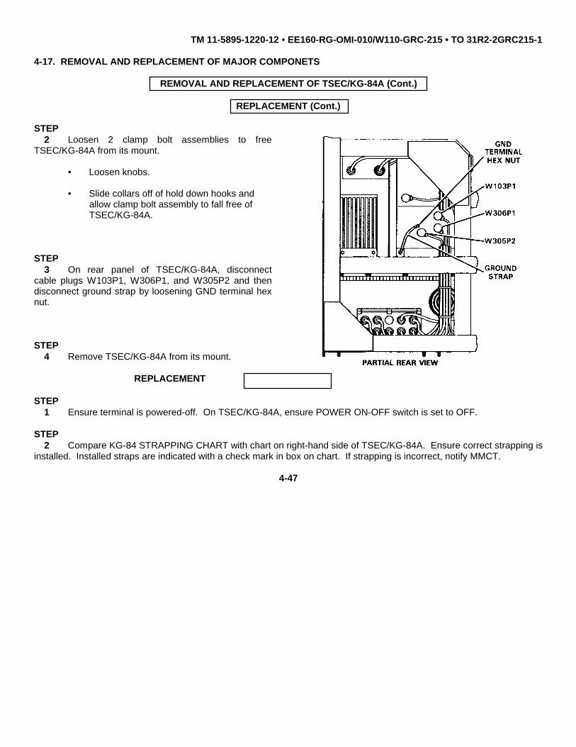
TM 11-5895-1220-12 • EE160-RG-OMI-010/W110-GRC-215 • TO 31R2-2GRC215-1
4-17. REMOVAL AND REPLACEMENT OF MAJOR COMPONETS
REMOVAL AND REPLACEMENT OF TSEC/KG-84A (Cont.)
REPLACEMENT (Cont.)
STEP2 Loosen 2 clamp bolt assemblies to free
TSEC/KG-84A from its mount.
• Loosen knobs.
• Slide collars off of hold down hooks andallow clamp bolt assembly to fall free ofTSEC/KG-84A.
STEP3 On rear panel of TSEC/KG-84A, disconnect
cable plugs W103P1, W306P1, and W305P2 and thendisconnect ground strap by loosening GND terminal hexnut.
STEP4 Remove TSEC/KG-84A from its mount.
REPLACEMENT
STEP1 Ensure terminal is powered-off. On TSEC/KG-84A, ensure POWER ON-OFF switch is set to OFF.
STEP2 Compare KG-84 STRAPPING CHART with chart on right-hand side of TSEC/KG-84A. Ensure correct strapping is
installed. Installed straps are indicated with a check mark in box on chart. If strapping is incorrect, notify MMCT.
4-47

TM 11-5895-1220-12 • EE160-RG-OMI-010/W110-GRC-215 • TO 31R2-2GRC215-1
4-17. REMOVAL AND REPLACEMENT OF MAJOR COMPONETS
REMOVAL AND REPLACEMENT OFTSEC/KG-84A (Cont.)
REPLACEMENT (Cont.)
KG-84A STRAPPING CHART
BD- PLUG FUNCTION STRAPPINGP2 ETCT [ ] BAL J6-J7 [ X ] UNBAL: J5-J6P3 J8-J9 J9-J10
A1 P4 XMTCTRL/CTTR [ ] BAL: J12-J13 [ X ] UNBAL: J11-J12P5 J15-J16 J14-J15P6 INTERFACE [ X ] KG-84A: J17A [ ] KG-84: J17BP2 TCTC [ ] BAL: J6-J7 [ X ] UNBAL: J5-J7P3 J9-J10 J8-J10 I
A2 P4 CLK LOCK [ ] DSBL: J20-J22 [ X ] ENBL: J21-J22P5 CTCD/CTRS [ ] BAL: J15-J16 [ X ] UNBAL J14-J16P7 J12-J13 J11-J13P6 CTCD/CTRS [ X ] KG-84A: J18-J19 [ ] KG-84: J17-J18P2 TIME OUT [ ] DSBL: J8-J9 [ X ] ENBL: J9-J10
A5 P3 VUX [ ] DSBL: J5-J7 [X] ENBL: J5-J6P4 FILL SELECT [ X ] KG-84A: J11-J12 [ ] KG-84: J12-J13
A6 P2 U UPDATE [ X ] ENBL: J7-J8 [ ] DSBL: J8-J9P2 REDI/O [ ] BAL: J14 [ X] UNBAL J6P3 J15 J7P4 STEP PULSE [ ] SGL: J8-J9 [ X ] DBL: J9-J10P5 TX CLOCK [ X ] CONT: J11-J12 [ ] GATED J12-J13
Change 1 4-48

TM 11-5895-1220-12 • EE160-RG-OMI-010/W110-GRC-215 • TO 31R2-2GRC215-1
4-17. REMOVAL AND REPLACEMENT OF MAJOR COMPONETS
REMOVAL AND REPLACEMENT OF ATU (Cont.)
REPLACEMENT (Cont.)
STEP3 Check battery installation date written on front
panel of TSEC/KG-84A. Replace battery when morethan 90 days old. Notify MMCT.
STEP4 Slide TSEC/KG-84A to its stationary position on
its mount and secure by tightening 2 clamp boltassemblies as follows:
• Slide collars onto hold down hooks on TSEC/KG-84A.
• Tighten knobs.
4-49

TM 11-5895-1220-12 • EE160-RG-OMI-010/W110-GRC-215 • TO 31R2-2GRC215-1
4-17. REMOVAL AND REPLACEMENT OF MAJOR COMPONETS
REMOVAL AND REPLACEMENT OFTSEC/KG-84A (Cont.)
REPLACEMENT (Cont.)
STEP5 Secure ground strap to rear panel of
TSEC/ KG-84A by tightening GND terminal hexnut.
STEP6 Make the following cable connections:
TSEC/KG-84ACable/plug Connector
W103P1 POWER J1W306P1 BLACK I/O J2W305P2 RED I/O J3
STEP7 Make the following control settings (these settings
should remain except for variations that are defined andpermitted by operating directives):
Switch Position
CLOCK: 1DATA MODE: 2DATA RATE (TX AND RX): 4TOGGLE SWITCHES (A-B): BSTEP PULSE INTVL: 1TTY MODE 5INTFC: 1DATA LENGTH: SYNCSYNC MODE: 4COMM MODE: 2+8/+0 SWITCH: +0
4-50

TM 11-5895-1220-12 • EE160-RG-OMI-010/W110-GRC-215 • TO 31R2-2GRC215-1
4-17. REMOVAL AND REPLACEMENT OF MAJOR COMPONETS
h. RN Modem.
REMOVAL AND REPLACEMENT OF RN MODEM
REPLACEMENT (Cont.)
STEP1 Perform terminal power-off sequence (para 2-8i).
STEP2 On front panel of RN Modem, disconnect cable plugs
W204P1, W312P2, W311P1, W306P2, and W109P1 fromconnectors J2, J1, J3, J4, and J5 in that order.
STEP3 Loosen 2 clamp bolt assemblies to
free RN Modem from its mount.
• Loosen knobs.
• Slide collars off of hold down hooks andallow clamp bolt assembly to fall free ofRN Modem.
4-51
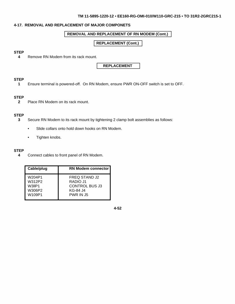
TM 11-5895-1220-12 • EE160-RG-OMI-010/W110-GRC-215 • TO 31R2-2GRC215-1
4-17. REMOVAL AND REPLACEMENT OF MAJOR COMPONETS
REMOVAL AND REPLACEMENT OF RN MODEM (Cont.)
REPLACEMENT (Cont.)
STEP4 Remove RN Modem from its rack mount.
REPLACEMENT
STEP1 Ensure terminal is powered-off. On RN Modem, ensure PWR ON-OFF switch is set to OFF.
STEP2 Place RN Modem on its rack mount.
STEP3 Secure RN Modem to its rack mount by tightening 2 clamp bolt assemblies as follows:
• Slide collars onto hold down hooks on RN Modem.
• Tighten knobs.
STEP4 Connect cables to front panel of RN Modem.
Cable/plug RN Modem connector
W204P1 FREQ STAND J2W312P2 RADIO J1W3llP1 CONTROL BUS J3W306P2 KG-84 J4W109P1 PWR IN J5
4-52

TM 11-5895-1220-12 • EE160-RG-OMI-010/W110-GRC-215 • TO 31R2-2GRC215-1
4-17. REMOVAL AND REPLACEMENT OF MAJOR COMPONETS
i. TT PS
REMOVAL AND REPLACEMENT OF TT PS (Cont.)
REPLACEMENT (Cont.)
WARNING
The TT PS weighs 62 lbs. There is no stop on mounting tray. Two-person lift required. Failure to usetwo-person lift may cause personal injury.
STEP1 Perform terminal power-off sequence (para 2-8i).
STEP2 On the TT PS, disconnect vehicle input power cable W100 (or applicable ac power cable W101/W102) from PWR
IN connector.
STEP3 Loosen 2 thumbscrews and allow clamp to fall free of TT PS. To prevent possible mechanical binding, loosen
thumbscrews evenly (that is, do not loosen one thumbscrew all the way before loosening the other thumbscrew).
STEP4 Loosen two clamp bolt assemblies to free TT PS from its mount.
• Loosen knobs.
• Slide collars off of holddown hooks and allowclamp bolt assembly tofall free Remove TT PSfrom its mount.
4-53

TM 11-5895-1220-12 • EE160-RG-OMI-010/W110-GRC-215 • TO 31R2-2GRC215-1
4-17. REMOVAL AND REPLACEMENT OF MAJOR COMPONETS
REMOVAL AND REPLACEMENT OF TT PS(Cont.)
REPLACEMENT (Cont.)
STEP1 Ensure terminal is powered-off. On the TT PS, ensure DC (or AC as applicable) ON-OFF switch is set to OFF.
STEP2 Place the TT PS on its mount and slide to
the rear; ensure TT PS connector P1 (located onrear of TT PS) interfaces with connector J1 onpower junction unit.
STEP3 Tighten 2 clamp bolt assemblies as follows:
• Slide collars onto hold down hooks on TT PS.
• Tighten knobs.
STEP4 Lift clamp in place and tighten 2 thumbscrews. To
prevent possible mechanical binding, tighten thumbscrewsevenly (that is, do not tighten one thumbscrew all the waybefore tightening the other thumbscrew).
STEP5 On TT PS, connect vehicle input power cable W100 (or user supplied auxiliary power cable) to PWR IN connector.
4-54

TM 11-5895-1220-12 • EE160-RG-OMI-010/W110-GRC-215 • TO 31R2-2GRC215-1
4-17. REMOVAL AND REPLACEMENT OF MAJOR COMPONETS (Cont.)
j. RFO.REMOVAL AND REPLACEMENT OF RFO (Cont.)
REMOVAL
WARNING
The RFO weighs 40 lbs. Two-person lift required. Failure to use two-person lift may cause personalinjury.
NOTE
If you want to retain TOD while RFO is removed from the rack, leave the RESET-OFF switch in theRESET position. This enables keep-alive batteries in the RFO to retain TOD for approximately 15minutes.
STEP1 Perform terminal power-off sequence (para 2-
8i).
STEP2 On RFO front panel, disconnect cable plugs
W106P1, W203P1, and W301P1 from +27 VDCPOWER connector, 10 MHZ OUT connector, andSYSTEM INTERFACE connector in that order.
STEP3 Loosen 2 thumbscrew clamps on lower front of
RFO and allow to fall free of unit.
STEP4 Remove RFO from its mount.
4-55

TM 11-5895-1220-12 • EE160-RG-OMI-010/W110-GRC-215 • TO 31R2-2GRC215-1
4-17. REMOVAL AND REPLACEMENT OF MAJOR COMPONETS
REMOVAL AND REPLACEMENT OF ATU (Cont.)
REPLACEMENT (Cont.)
NOTE
The RESET-OFF switch on the replacement RFO may have been set to the RESET position to retainTOD. If this is the case, do not set RESET-OFF switch to OFF position.
STEP1 Ensure terminal is powered-off. On RFO, ensure RESET-OFF switch is set to OFF.
STEP2 Place RFO on its mount.
STEP3 Secure RFO to its mount by tightening 2 thumbscrew clamps.
STEP4 Connect cables to RFO front panel as follows:
Cable/plug RFO connector
W106Pl +27 VDC POWERW203P1 10 MHZ OUTW301P1 SYSTEM INTERFACE
4-56

TM 11-5895-1220-12 • EE160-RG-OMI-010/W110-GRC-215 • TO 31R2-2GRC215-1
4-17. REMOVAL AND REPLACEMENT OF MAJOR COMPONETS
REMOVAL AND REPLACEMENT OF I/O UNIT
REMOVAL
WARNING
The I/O Unit weighs 50 lbs. Two-person lift required. Failure to use two-person lift may cause personalinjury.
STEP1 Perform terminal power-off sequence
(para 2-8i).
STEP2 On I/O Unit front panel, disconnect
WllOP1, W305P1, and W310P1 from POWERJ1 connector, KG-84 DATA J4 connector, andCONTROL DATA J2 connector respectively.
STEP3 Loosen 2 clamp bolt assemblies to free
I/O Unit from its mount.
• Loosen knobs.
• Slide collars off of hold downhooks and allow clamp boltassembly to fall free of I/O Unit.
4-57

TM 11-5895-1220-12 • EE160-RG-OMI-010/W110-GRC-215 • TO 31R2-2GRC215-1
4-17. REMOVAL AND REPLACEMENT OF MAJOR COMPONETS
REMOVAL AND REPLACEMENT OF I/O UNIT (Cont.)
REMOVAL (Cont.)
STEP4 Remove I/O Unit from its mount.
REPLACEMENT
STEP1 Ensure terminal is powered-off. On I/O Unit, ensure POWER ON switch is set to off (down) position.
STEP2 Place I/O Unit on its mount.
STEP3 Secure I/O Unit to its mount by tightening 2 clamp bolt assemblies as follows:
• Slide collars onto hold down hooks on I/O Unit.
• Tighten knobs.
STEP4 Connect cables to I/O Unit front panel.
Cable/plug I/O Unit connector
W11OP1 POWER J1W205P1 KG-84 DATA J4W310P1 CONTROL DATA J2
4-58

TM 11-5895-1220-12 • EE160-RG-OMI-010/W110-GRC-215 • TO 31R2-2GRC215-1
4-17. REMOVAL AND REPLACEMENT OF MAJOR COMPONETS
REMOVAL AND REPLACEMENT OF WHIP ANTENNA
REMOVALl. Whip Antenna
STEP1 Perform terminal power-off sequence (para 2-8i).
STEP2 Slide insulator boot above the Whip Antenna base
section. Remove the base section (turn counterclockwise) fromthe Antenna Base.
STEP3 Disassemble 4 sections of the Whip Antenna.
STEP4 Loosen 4 captive screws securing antenna mount
access cover. Remove access cover.
STEP5 Using 1/2 in. socket wrench, remove and retain
hex nut securing antenna cable W1 to Antenna Base.
4-59

TM 11-5895-1220-12 • EE160-RG-OMI-010/W110-GRC-215 • TO 31R2-2GRC215-1
4-17. REMOVAL AND REPLACEMENT OF MAJOR COMPONETS
REMOVAL AND REPLACEMENT OF WHIP ANTENNA (Cont.)
REMOVAL (Cont.)
STEP6 Using 9/16 in. Socket wrench, remove and retain 4
mounting bolts, lockwashers and flatwashers. RemoveAntenna Base from antenna mount.
REPLACEMENT
STEP1 Using 9/16 in. socket wrench, secure Antenna Base to
antenna mount by tightening 4 mounting bolts, lockwashers andflatwashers retained in removal step 6.
STEP2 Using 1/2 in. socket wrench, secure antenna cable W1 to Antenna Base by tightening hex nut retained in removal
step 5.
STEP3 Secure access cover to antenna mount by tightening 4 captive screws.
STEP4 Assemble 4 sections of the Whip Antenna. Slide the insulator boot onto base section. Place the large threaded
butt of the base section on Antenna Base and turn clockwise until secure. Do not over-tighten.
4-60

TM 11-5895-1220-12 • EE160-RG-OMI-010/W110-GRC-215 • TO 31R2-2GRC215-1
4-17. REMOVAL AND REPLACEMENT OF MAJOR COMPONETS
REMOVAL AND REPLACEMENT OF WHIP ANTENNA (Cont.)
REPLACEMENT (Cont.)STEP
5 Pull the antenna insulator boot over the spring section of the Antenna Base.
m. Antenna Cable W1. Tool Kit, Electronic Equipment TK-101/G is required to remove and replace AntennaCable W1.
REMOVAL AND REPLACEMENT OF ANTENNA CABLE W1
REMOVALSTEP
1 Perform terminal power-off sequence (para 2-8i).
STEP2 Loosen 4 captive screws securing antenna mount
access cover. Remove access cover.
STEP3 Using 1/2 in. socket wrench, remove and retain hex nut
securing antenna cable W1 to Antenna Base.
4-61

TM 11-5895-1220-12 • EE160-RG-OMI-010/W110-GRC-215 • TO 31R2-2GRC215-1
4-17. REMOVAL AND REPLACEMENT OF MAJOR COMPONETS
REMOVAL AND REPLACEMENT OF ANTENNA CABLE W1 (Cont.)
REMOVAL (Cont.)
REPLACEMENT
STEP1 Insert antenna cable W1 through the appropriate slot in the ATU Safety Cap and secure to the antenna matching
capacitor on the ATU by tightening cross-head screw (retained in removal step 4).
STEP2 Route antenna cable W1 through vehicle wall to Antenna Base. Using 1/2 in. socket wrench, secure antenna
cable W1 to Antenna Base by tightening hex nut (retained in removal step 3).
STEP3 Secure access cover to antenna mount by tightening 4 captive screws.
4-62

TM 11-5895-1220-12 • EE160-RG-OMI-010/W110-GRC-215 • TO 31R2-2GRC215-1
4-17. REMOVAL AND REPLACEMENT OF MAJOR COMPONETS
n. Battery Case/Charger Batteries. Key set, socket head (metric) is required to remove and replace batteries inthe battery case/charger.
REMOVAL AND REPLACEMENT OF BATTERIES
REMOVAL
CAUTION
This equipment contains components that are sensitive to damage by ESD. Improper handling will resultin component and assembly failure. Use extreme care when handling. Refer to DOD-HDBK-263 forproper handling procedures.
STEP1 Loosen four captive hex head screws 1 in the Battery Case/Charger using 5mm hexagonal wrench.
STEP.2 Lift cover 2 and carefully tilt back
STEP3 Disconnect connectors J2 and J3 3 from batteries 4
Change 1 4-63

TM 11-5895-1220-12 • EE160-RG-OMI-010/W110-GRC-215 • TO 31R2-2GRC215-1
4-17. REMOVAL AND REPLACEMENT OF MAJOR COMPONETS
REMOVAL AND REPLACEMENT OF BATTERIES (Cont.)
REMOVAL (Cont.)
NOTE
Observe orientation of batteries 4 and position of connectors J2 and J3 before removingbatteries.
STEP4 Remove batteries 4 from Battery Case/Charger 5 .
REPLACEMENT
STEP1 Install batteries 4 into Battery/Case Charger 5
STEP2 Reconnect connectors J2 and J3 3 to batteries 4
Change 1 4-64

TM 11-5895-1220-12 • EE160-RG-OMI-010/W110-GRC-215 • TO 31R2-2GRC215-1
4-17. REMOVAL AND REPLACEMENT OF MAJOR COMPONETS
REMOVAL AND REPLACEMENT OF BATTERIES (Cont.)
REPLACEMENT (Cont.)
STEP3 Carefully align cover 2 with mounting holes on the Battery/Case Charger 5 and secure by tightening four
captive hex head screws 1 .
FRONT VIEW
Change 2 4-65

TM 11-5895-1220-12 • EE160-RG-OMI-010/W110-GRC-215 • TO 31R2-2GRC215-1
4-17. REMOVAL AND REPLACEMENT OF MAJOR COMPONETS
o. ATU Safety Cap and Matching Capacitor. Tool Kit, Electronic Equipment TK-101/G is required to install orremove the ATU safety cap or matching capacitor.
INSTALLATION OF ATU SAFETY CAP
NOTE
The ATU Safety Cap is supplied with attaching hardware.
Once installed, the Safety Cap is not required to be removed during normal operation. When changingantenna configurations (i.e. whip to NVIS or vice versa), access holes have been provided in the SafetyCap to facilitate reconnection of antenna cable W1.
Prior to ATU SAFETY CAP installation, ensure power is off. Perform Terminal power-off sequence inaccordance with para. 2-8i.
STEP1 Remove the antenna cable W1 connection to the antenna matching capacitor. Retain the crosshead screw.
Change 2 4-66

TM 11-5895-1220-12 • EE160-RG-OMI-010/W110-GRC-215 • TO 31R2-2GRC215-1
4-17. REMOVAL AND REPLACEMENT OF MAJOR COMPONENTS (con't)
INSTALLATION OF ATU SAFETY CAP (Cont)
NOTE
If an antenna matching capacitor is not already installed, it is recommended it be installed now sothat the ATU safety cap will not have to be removed and re-installed later. Remove antenna cableW1 and attach the antenna matching capacitor by screwing it directly onto the existing antennainsulator. There are threaded holes at both ends of the matching capacitor. Position the ’nut’ endof the capacitor against the antenna insulator
STEP
2 Attach 3ea screws, lock washers, and flat washers supplied with the ATU safety cap to the pre-threaded holes inthe cap. The lockwasher should be placed between the screw head and the flat washer.
STEP3 Temporarily position the safety cap over the matching capacitor and up against the ATU so that one of the three
inner slots on the cap is over the inner screw hole of the matching capacitor. Identify those 3 screws securing thecapacitor tuning assembly to the ATU frame that coincide with those on the safety cap.
Change 2 4-67

TM 11-5895-1220-12 • EE160-RG-OMI-010/W110-GRC-215 • TO 31R2-2GRC215-1
1 4-17. REMOVAL AND REPLACEMENT OF MAJOR COMPONENTS (con't)
INSTALLATION OF ATU SAFETY CAP (Cont.)
STEP4 Remove and retain three of the six screws (identified in in step 3) securing the tuning capacitor assembly
to the outer frame of the ATU.
STEP5 Position the Cap over the end of the matching capacitor and fasten securely to the ATU frame using the three
captive screws on the cap.
Change 2 4-68

TM 11-5895-1220-12 • EE160-RG-OMI-010/W110-GRC-215 • TO 31R2-2GRC215-1
4-17. REMOVAL AND REPLACEMENT OF MAJOR COMPONENTS (con't)
INSTALLATION OF ATU SAFETY CAP (Cont.)
STEP6 Insert Antenna Cable (W1) into the outer slot for NVIS operation or the inner slot for whip operation. Using a screw
driver, secure antenna cable (W1) to the matching capacitor using existing screw.
REMOVAL OF ATU SAFETY CAP
STEP1 Perform Terminal power-off sequence (para 2-8i).
STEP2 Using a cross-tip screwdriver, remove and retain cross-head screw securing antenna cable W1 to antenna
matching capacitor on ATU. Carefully pull W1 out of the safety cap.
Change 2 4-69

TM 11-5895-1220-12 • EE160-RG-OMI-010/W110-GRC-215 • TO 31R2-2GRC215-1
4-17. REMOVAL AND REPLACEMENT OF MAJOR COMPONENTS (con't)
REMOVAL OF ATU SAFETY CAP (Cont.)
STEP3 Using a screwdriver, remove and retain the 3 screws securing the safety cap to the ATU. This will free the safety
cap from the ATU frame.
STEP4 After the cap is removed, secure the 3 screws retained during cap installation (step 4 above) into the 3 vacant
holes. This will completely secure the antenna tuning assembly to the ATU frame.
4-18. CLEANING
CAUTION
Never use steel wool, scouring pads or powders, or harsh chemical agents, such as lye solution whencleaning your equipment.
Use a dry, clean, lint-free cloth, (item 1, Appendix E) or brush (item 2, Appendix E) to remove dust or dirt. If needed,moisten the cloth or brush with a mild solution of detergent or soap and water. After cleaning, wipe dry with a clean cloth.
Change 2 4-70

TM 11-5895-1220-12 • EE160-RG-OMI-010/W110-GRC-215 • TO 31R2-2GRC215-1
Section VI. PREPARATION FOR STORAGE OR SHIPMENT
4-19. GENERAL
WARNING
Before shipment or inactive storage of 30 days or more, contact MMCT toremove batteries in the RFO or ECCM Module. Navy personnel contactChief Watch Officer. Air Force personnel contact Maintenance Control.
a. Army. Before placing equipment in administrative storage, insure that equipment is operational. Ifoperational, put into storage using appropriate corrosion control techniques. When removing from storage, again performoperational tests and Unit PMCS (if available) to determine mission capability.
b. Navy. Refer to NAVSUP PUB 503.
c. Air Force. Refer to AFM 66-267 (storage) and AFR 67-31 (shipment).
4-20. MARKING
The marking on the exterior of the container shall be in accordance with MIL-STD-129H.
Change 2 4-71/(4-72 blank)

TM 11-5895-1220-12 • EE160-RG-OMI-010/W110-GRC-215 • TO 31R2-2GRC215-1
APPENDIX A
REFERENCES
A-1. SCOPE
This appendix lists all publications that are referenced in this manual or that contain information applicable to themaintenance of the Team Terminal.
A-2. PUBLICATIONS
Chemical, Biological, and Radiological (CBR)Decontamination.......................................... ............................................................................................... TM 3-220
Consolidated Index of Army Publications andBlank Forms......................................... ...............................................................................................DA PAM 25-30
Destruction of Army Electronics Materiel to PreventEnemy Use...........................................................................................................................................TM 750-244-2
Electrostatic Discharge Control Handbookfor Protection of Electrical and ElectronicParts, Assemblies and Equipment(Excluding Initiated Explosive Devices)............................................................................................ DOD-HDBK-263
Hand Receipt Covering Content of Componentsof End Item (COEI), Basic Issue Items (BII),and Additional Authorization List (AAL) forRadio Set AN/GRC-215 (NSN 5895-01-156-0456)............................................................ TM 11-5895-1220-10-HR
Intermediate Direct Support and GeneralSupport Maintenance Manual forRadio Set AN/GRC-215 (NSN 5895-01-156-0456)...................................................................TM 11-5895-1220-34
EE160-RG-INM-010/Wll0-GRC215TO 31R2-2GRC215-2
Issue of Ships Maintenance andMaterial Managements (3-M) Manual............... ...................................................................... OPNAVINST 4790.4A
Maintenance Data Collection System...................................................................................................................AFM 66-267
Naval Supply Publication 2002 Navy StockList of Publications and Forms........................ ....................................................................................NAVSUP 2002
Operator’s, Organizational, Direct Support, andGeneral Support Maintenance Manual for(Including Repair Parts and Special Tools List)IAntenna AS-2259/GR(NSN 5985-00-106-6130).... ................................................................TM 11-5985-379-14&P
Change 2 A-1

TM 11-5895-1220-12 • EE160-RG-OMI-010/W110-GRC-215 • TO 31R2-2GRC215-1
A-2. PUBLICATIONS (Cont.)
Operator’s and Organizational Maintenance Manual(Including Repair Parts and Special Tools List)for Communications Security Equipment TSEC/KG-84A(NSN 5810-01-146-3260).......................................................................................................TM 11-5810-308-12&P
Operator’s and Organizational Maintenance Manual(Including Repair Parts and Special Tools List)for Cryptographic Speech Equipment TSEC/KY-65(NSN 5810-01-050-2501), AC/DC Power SupplyZ-AKE/TSEC (NSN 6310-01-050-9536), and Battery PackAssembly Z-AKG/TSEC (NSN 5810-01-050-2498)................................................................TM 11-5810-280-12&P
Operator’s and Organizational Maintenance Manualfor Communications Security Equipment KOI-18/TSEC,General Purpose Tape Reader, KYK-13/TSEC, ElectronicTransfer Device, KYX-15/TSEC, Net Control Device,and KYX-15A/TSEC, Net Control Device....................................................................................TM 11-5810-292-12
Operating and Troubleshooting Guidefor Regency NetVol.2Communications Terminals AN/TRC-179(V)l & 3and Radio Set AN/GRC-215................... ............................................................................... TB 11-5895-1218-12-2
Navy EE150-LQ-OMI-020/AN/TRC179VlAir Force TO 31R2-2TRC179-21-2
Packing Instructions................................. ................................................................................................. NAVSUP PUB 503
Packing, Packaging and Handlingof Electronic Equipment.............................. ........................................................................................ MIL-E-17555H
Preservation, Packaging, and Packing of MilitarySupplies and Equipment Volume 2.................... .......................................................................... NAVSUP PUB 503
Release for Shipment of Ground CommunicationElectronic Cryptographic Equipment........................ ................................................................................. AFR 67-31
Reporting of Item and Packing Discrepancies......SECNAVINST 4355.18
Reporting of Transportation Discrepanciesand Shipment................................. .....................................................................................NAVSUPINST 4610.33C
Safety Measures to be Observed when Installing andUsing Whip Antennas, field-type Masts, Towers, Antennas,and Metal Poles that are used with Communication, Radar,and Direction Finder Equipment...............................................................................................................TB 43-0129
System Network Manager Planning Guidefor Regency Net (S)Vol.1Communications Terminals AN/TRC-179(V)1 & 3and Radio Set AN/GRC-215............ ...................................................................................... TB 11-5895-1218-12-1
Navy EE150-LQ-OMI-030/(S)AN/TRC179V1Air Force TO 31R2-2TRC179-21-1 ‘--
Change 2 A-2

TM 11-5895-1220-12 • EE160-RG-OMI-010/W110-GRC-215 • TO 31R2-2GRC215-1
A-2. PUBLICATIONS (Cont.)
The Army Maintenance Management System (TAMMS).............................................................................DA Pam 738-750
Unit Maintenance Repair Parts and Special ToolsList for Radio Set AN/GRC-215(NSN 5895-01-156-0456)....................................................................................................... TM 11-5895-1220-20P
EE160-RG-MIB-010/Wl10-GRC215TO 31R2-2GRC215-4
Unit, Intermediate Direct Support, andGeneral Support Maintenance Manual forModem, Digital Data MD-1204/G(NSN 5895-01-210-5235)..........................................................................................................TM 11-5895-1307-24
EE163-HK-MMI-010/Wl10-MD1204TO 31R2-4-585-2
Unit, Intermediate Direct Support, andGeneral Support Maintenance Manual forConverter CV-3968/GRC-215........................... ........................................................................TM 11-5895-1309-24(NSN 5895-01-205-0654) EE162-FG-MMI-010/Wl10-CV3968
TO 31R2-2GRC215-22
Unit, Intermediate Direct Support, andGeneral Support Maintenance Manual forOscillator, Frequency Reference 0-1836/G(NSN 5895-01-205-0643)..........................................................................................................TM 11-5895-1312-24
EE169-KL-MMI-010/Wl10-01836TO 31R2-4-564-2
Unit, Intermediate Direct Support, andGeneral Support Maintenance Manual forController, Receiver-Transmitter C-11670/G(NSN 5895-01-205-0662)..........................................................................................................TM 11-5895-1315-24
EE005-FG-MMI-010/Wl10-C11670GTO 31R2-4-567-2
Unit, Intermediate Direct Support, andGeneral Support Maintenance Manual forReceiver-Transmitter, Radio RT-1511/GRC-215(NSN 5895-01-205-6180)..........................................................................................................TM 11-5895-1318-24
EE150-LS-MMI-010/Wl10-RT1511TO 31R2-2GRC215-42
Unit, Intermediate Direct Support, andGeneral Support Maintenance Manual forAmplifier, Power AM-7301/GRC-215(NSN 5895-01-205-0884)..........................................................................................................TM 11-5895-1319-24
EE020-FH-MMI-010/Wll0-AM7301TO 31R2-4-574-2
Change 2 A-3

TM 11-5895-1220-12 • EE160-RG-OMI-010/W110-GRC-215 • TO 31R2-2GRC215-1
A-2. PUBLICATIONS (Cont.)
Unit, Intermediate Direct Support, andGeneral Support Maintenance Manual forPower Supply PP-8170/GRC-215(NSN 5895-01-205-0824)..........................................................................................................TM 11-5895-1320-24
EE010-JM-PLD-010/Wl10-PP8170TO 31R2-2GRC215-62
Unit, Intermediate Direct Support, andGeneral Support Maintenance Manual forInput-Output Unit MX-10819/GRC-215(NSN 5895-01-205-0655)..........................................................................................................TM 11-5895-1322-24
EEl19-ND-MMI-010/Wl10-MX10819TO 31R2-2GRC215-32
Unit, Intermediate Direct Support, andGeneral Support Maintenance Manual forCoupler, Antenna CU-2351/GRC-215(NSN 5895-01-205-0878)............................................................................................................TM 11-5895-378-24
EE111-LM-MMI-010/Wl10-CU2351TO 31R2-4-579-2
Unit, Intermediate Direct Support, andGeneral Support Maintenance Manual forMounting Base, Electrical EquipmentMT-6452/GRC-215(NSN 5895-01-207-8991)..........................................................................................................TM 11-5895-1321-24EE005-LC-MMI-010/Wl10-MT6452TO 31R2-2GRC215-52
Change 2 A-4

TM 11-5895-1220-12 • EE160-RG-OMI-010/W110-GRC-215 • TO 31R2-2GRC215-1
APPENDIX B
MAINTENANCE ALLOCATION
Section I. INTRODUCTION
B-1. GENERAL
This appendix provides a summary of the maintenance operations for Radio Set AN/GRC-215. It authorizes levelsof maintenance for specific maintenance functions on repairable items and components and the tools and equipmentrequired to perform each function. This appendix may be used as an aid in planning maintenance operations.
B-2. MAINTENANCE FUNCTION
Maintenance functions will be limited to and defined as follows:
a. Inspect. To determine the serviceability of an item by comparing its physical, mechanical, and/or electricalcharacteristics with established standards through examination.
b. Test. To verify serviceability and to detect incipient failure by measuring the mechanical or electricalcharacteristics of an item and comparing those characteristics with prescribed standards.
c. Service. Operations required periodically to keep an item in proper operating condition, i.e., to clean(decontaminate), to preserve, to drain, to paint, or to replenish fuel, lubricants, hydraulic fluids, or compressed air supplies.
d. Adjust. To maintain, within prescribed limits, by bringing into proper or exact position, or by setting theoperating characteristics to the specified parameters.
e. Aline. To adjust specified variable elements of an item to bring about optimum or desired performance.
f. Calibrate. To determine and cause corrections to be made or to be adjusted on instruments or testmeasuring and diagnostic equipment used in precision measurement. Consists of comparisons of two instruments, one ofwhich is a certified standard of known accuracy, to detect and adjust any discrepancy in the accuracy of the instrumentbeing compared.
g. Install. The act of emplacing, seating, or fixing into position an item, part, module (component orassembly) in a manner to allow the proper functioning of the equipment or system.
h. Replace. The act of substituting a serviceable like type part, subassembly, or module (component orassembly) for an unserviceable counterpart.
B-1

TM 11-5895-1220-12 • EE160-RG-OMI-010/W110-GRC-215 • TO 31R2-2GRC215-1
i. Repair. The application of maintenance services (inspect, test, service, adjust, aline, calibrate, replace) orother maintenance actions (welding, grinding, riveting, straightening, facing, remachin- M ing, or resurfacing) torestore serviceability to an item by correc-ting specific damage, fault, malfunction, or failure in a part, sub-assembly,module (component or assembly), end item, or system.
i. Overhaul. That maintenance effort (service/action) necessary to restore an item to a completelyserviceable/operational condition as prescribed by maintenance standards (i.e., DMWR) in appropriate technicalpublications. Overhaul is normally the highest degree of maintenance performed by the Army. Overhaul does not normallyreturn an item to like new condition.
k. Rebuild. Consists of those services/action necessary for the restoration of unserviceable equipment to alike new condition in accordance with original manufacturing standards. Rebuild is the highest degree of materialmaintenance applied to Army equipment. The rebuild operation includes the act of returning to zero those agemeasurements (hours, miles, etc.) considered in classifying Army equipments/components.
B-3. COLUMN ENTRIES
a. Column 1, Group Number. Column 1 lists group numbers, the purpose of which is to identify components,assemblies, subassemblies, and modules with the next higher assembly.
b. Column 2, Component/Assembly. Column 2 contains the noun names of components, assemblies,subassemblies, and modules for which maintenance is authorized.
c. Column 3, Maintenance Functions. Column 3 lists the functions to be performed on the item listed incolumn 2. When items are listed without maintenance functions, it is solely for purpose of having the group numbers in theMAC and RPSTL coincide.
d. Column 4, Maintenance Level. Column 4 specifies, by the listing of a work time figure in the appropriatesubcolumn(s), the lowest level of maintenance authorized to perform the function listed in column 3. This figure representsthe active time required to perform that maintenance function at the indicated level of maintenance. If the number orcomplexity of the tasks within the listed maintenance function vary at different maintenance levels, appropriate work timefigures will be shown for each category. The number of task-hours specified by the work time figure represents theaverage time required to restore an item (assembly, subassembly, component, module, end item, or system) to aserviceable condition under typical field operating conditions. This time includes preparation time, troubleshooting time,and quality assurance/quality control time in addition to the time required to perform the specific tasks identified for themaintenance functions authorized in the maintenance allocation chart. Sub-columns of column 4 are as follows:
B-2

TM 11-5895-1220-12 • EE160-RG-OMI-010/W110-GRC-215 • TO 31R2-2GRC215-1
UNIT
C - Operator/CrewO - Organizational/Unit
INTERMEDIATE
F - Direct SupportH - General SupportL - Specialized Repair Activity (SRA)
DEPOT
D - Depot
e. Column 5, Tools and Equipment. Column 5 specifies by code, those common tool sets (not individualtools) and special tools, test, and support equipment required to perform the designated function.
f. Column 6, Remarks. Column 6 contains an alphabetic code which leads to the remark in section IV,Remarks, which is pertinent to the item opposite the particular code.
B-4. TOOL AND TEST EOUIPMENT REOUIREMENTS (Sect. III)
a. Tool or Test Equipment Reference Code. The numbers in this column coincide with the numbers used inthe tools and equipment column of the MAC. The numbers indicate the applicable tool or test equipment for themaintenance functions.
b. Maintenance Level. The codes in this column indicate the maintenance level allocated to use the tool ortest equipment.
c. Nomenclature. This column lists the noun name and nomenclature of the tools and test equipmentrequired to perform the maintenance functions.
d. National/NATO Stock Number. This column lists the National/ NATO stock number of the specific tool ortest equipment.
e. Tool Number. This column lists the manufacturer’s part number of the tool followed by the Federal SupplyCode for manufacturers (5-digit) in parentheses.
B-5. REMARKS (Sect. IV)
a. Reference Code. This code refers to the appropriate item in section II, column 6.
b. Remarks. This column provides the required explanatory information necessary to clarify items appearingin section II.
B-3

TM 11-5895-1220-12 • EE160-RG-OMI-010/W110-GRC-215 • TO 31R2-2GRC215-1
Section II. MAINTENANCE ALLOCATION CHART
FOR
RADIO SET AN/GRC-215
(1) (2) (3) (4) (5) (6)
GROUP MAINTENANCE MAINTENANCE LEVEL TOOLS ANDNUMBER COMPONENT ASSEMBLY FUNCTION C O F H D EQUIPMENT REMARKS
00 Radio Set Install 2.0 2 VAN/GRC-215 Test 0.1 12 A,B(A3023743) Repair 0.5 1,11,13,14,19 A
Calibrate 0.5 8,9 CTest 1.0 3-6Repair 1.0 2,10,11,19,20 DOverhaul 120.0 TBD
01 Antenna Assembly Install 0.3AS-3809/G (A3034093) E2 Replace 0.5 1
Repair 0.1 E02 Receiver/Transmitter, Replace 0.1 1
Radio RT-1511/GRC-215 Repair F(A3023795) A1
03 Mounting Base, Elect. Replace0.21Equipment MT-6452/GRC- Repair G215 (A3023796) A2
04 Amplifier, Power Replace 0.1 1AM-7301/GRC-215 Repair H(A30O23797) A3
05 Battery Case/Charger Replace 0.05(A3023798) A14 Repair 0.1 11,14 I
Test 1.0 3-6,18Repair 1.0 2,7,10,14,18 J
0501 Battery Case Assembly Repair 1.0 K(A3030350) A14A1
050101 Circuit Card Assembly, Replace 0.5 2,18Battery Case (A3031535) Repair 1.0 KA14A1A1
06 Coupler, Antenna Replace 0.2 1CU-2351/GRC-215 Repair L(A3023799) A4
07 Converter CV-3968/GRC- Replace 0.05215 (A3023801) A13 Repair M
07 Harness, Electrical Replace 0.05(A3023804) Repair 0.5 2
08 Modem, Digital Data Replace 0.1MD-1204/G (A3023769) A8 Repair N
09 Power Supply Replace 0.1 1PP-8170/GRC-215 Repair O(A3023808) A9
Change 1 B-4

TM 11-5895-1220-12 • EE160-RG-OMI-010/W110-GRC-215 • TO 31R2-2GRC215-1
SECTION II. MAINTENANCE ALLOCATION CHART
FOR
RADIO SET AN/GRC-215
(1) (2) (3) (4) (5) (6)
GROUP MAINTENANCE MAINTENANCE LEVEL TOOLS ANDNUMBER COMPONENT ASSEMBLY FUNCTION C O F H D EQUIPMENT REMARKS
10 Oscillator, Reference Replace 0.1 1Frequency 0-1836/G Repair P(A3023762) A10
11 Rack/Pallet Assembly Test 1.0 3(A3023810) All Repair 1.0 2,15,16
1101 Power Junction Assy. Repair 1.0 2,15,16 K(A3023815) A11A1
1102 Mount, Controller Replace 0.5 2(A3023816) Repair 1.0 2
1103 Mount, RFO Replace 0.5 2(A3023817) Repair 1.0 2
1104 Mount, Modem Replace 0.5 2(A3023818) Repair 1.0 2
1105 Mount Assy., PDU Replace 0.5 2(A3023952) Repair 1.0 2
1106 Control Junction Unit Repair 1.0 2,15,16 K(A3028234) AllA2
1107 Bypass Assy., KG-84A Repair 0.5 2(A3029355)
1108 Plenum Assembly, Fan Repair 1.0 2(A3032075)
1109 Stowage Box Assembly Repair 0.5 2(A3078159)
12 I/O Unit MX-10819/GRC- Replace 0.1215 (A3023811) A12 Repair Q
13 Vehicle Installation Repair 0.5Kit MK-2211/GRC-215(A3023812)
14 Cable Assembly, Power, Replace 0.1 1Elec. CX-13348/GRC-215 Test 0.5 3(A3023949) Repair 0.5 2
15 Adapter, Antenna Install 0.1MX-9313/GR Replace 0.1
16 Antenna, NVIS Install 0.5 1,17AS-2259/GR Replace 0.5 1,17
Repair R
Change 1 B-5

TM 11-5895-1220-12 • EE160-RG-OMI-010/W110-GRC-215 • TO 31R2-2GRC215-1
SECTION II. MAINTENANCE ALLOCATION CHART
FOR
RADIO SET AN/GRC-215
(1) (2) (3) (4) (5) (6)
GROUP MAINTENANCE MAINTENANCE LEVEL TOOLS ANDNUMBER COMPONENT ASSEMBLY FUNCTION C O F H D EQUIPMENT REMARKS
17 TSEC/Battery Pack Replace 0.1 TZ-AKGITSEC Repair
18 Key Generator, Replace 0.1 1Electronic TSEC/KG-84A Repair S
19 COMSEC Device Replace 0.1TSEC/KY-65A Repair T
20 AC/DC Power Supply Replace 0.1TSEC Z-AKE/TSEC Assy. Repair T
21 Cable Assembly and Reel Replace 0.05CG-3883/G (A3034219) Repair 0.1 1
Test 0.05 3
Change 1 B-6

TM 11-5895-1220-12 • EE160-RG-OMI-010/W110-GRC-215 • TO 31R2-2GRC215-1
SECTIN III. TOOL AND TEST EQUIPMENT REQUIREMENTS
FOR
RADIO SET AN/GRC-215
REF. MAINT. NATIONAL/NATO TOOL*CODE LEVEL NOMENCLATURE STOCK NUMBER NUMBER
1 0 Tool Kit TK-101/G 5180-00-064-5178
2 H Tool Kit, Elec. TK-17 5180-01-195-0855 JENSEN(Incl. Metric) JTK-17RM
3 H Multimeter, Digital AN/USM-486 6625-01-145-2430 FLUKE8050A-01
4 H Oscilloscope AN/USM-488 6625-01-187-7847 TEK 2235L
5 H Power Supply PP-8202/G * 6130-00-160-0827 HP-6274B
6 H Test Set, Battery Set 6625-01-263-5488 MX 950577-801TS-4253/GRC-215
7 H Maintenance Kit, PCB MX-10897/G 5895-01-267-9473 Pace ModelRNR PIN8007-0117
8 O,H Cable Assembly (TOD) and Reel 5995-01-326-0142 A3034219CG-3883/G (50 ft.)
9 H Receiver, Radio R-2171/TRC ** 5820-01-097-2501 MX-1102TR
10 H Repair Kit, PCB MK-772/U 5999-00-757-7042
11 O,H Static Control Service Kit 4940-01-168-2044 3M 8012
12 0 Multimeter, Digital AN/PSM-45A 6625-01-265-6000 FLUKE 27/FM
13 0 Screwdriver Set, Torque 5120-00-127-2525 EDP 85002-00(1-30 in-lb)
14 O,H Key Set, Socket Head (Metric) 5120-01-112-9599
15 H Removal Tool, Buss Terminal DEUTSCH5120-01-097-5219 CTJ-R065120-01-232-0023 CTJ-R12
16 H Insertion/Removal Tools, Pin ***(as appropriate)
17 C,O Hammer, Hand 2.5 lb. 5120-00-203-4856 EMHART 102DG
18 H Workstation, Static 4940-01-087-3458 3M 8021
19 O,H Pliers, Slip-Joint 5120-00-624-806520 H Puller, Fuse (Type I) 5120-00-224-9453
* PP-8214/G provides identical 6130-00-150-0028capability when source poweris 230V, 50 cycle. Air Forceuse only.
Change 1 B-7

TM 11-5895-1220-12 • EE160-RG-OMI-010/W110-GRC-215 • TO 31R2-2GRC215-1
Section III. TOOL AND TEST EQUIPMENT REQUIREMENTS
FOR
RADIO SET AN/GRC-215
REF. MAINT. NATIONAL/NATO TOOL*CODE LEVEL NOMENCLATURE STOCK NUMBER NUMBER
** Timing Unit, Signal TD-1436/G 6625-01-274-5052provides identical TOD sourceduring periods of satellitenon-availability or denial.
*** Wire/contact tools for size20, 16, and 12 wire.
Size 20 5120-00-915-4587 DeutschM15570-20M83723/31-20
Size 16 5120-00-915-4588 DeutschM15570-16M83723/31-16
Size 12 5120-00-132-5451 Deutsch81515-12MS3160-
Change 1 B-8

TM 11-5895-1220-12 • EE160-RG-OMI-010/W110-GRC-215 • TO 31R2-2GRC215-1
SECTION IV. REMARKS
FOR
RADIO SET AN/GRC-215
REFERENCE CODE REMARKS
A Unit maintenance fault isolates and replaces defective 0-1836/G, PP-8170/GRC-215, AM-7301/GRC-215, CU-2351/GRC-215, C-11670/G,M/P Receiver-Exciter A3023805, TSEC/KY-65, TSEC/KG- 84A, Z-AKE/TSEC, Z-AKG/TSEC, MT-6452/GRC-215, Battery Case/ ChargerA3023798 and fault isolates and replaces defective subassemblies/CCAsin the MD-1204/G and MX-10819/GRC-215. Unit maintenance alsoreplaces the following non-repairable components: AS-3805/GRC-215,H-251/U, and H-356/G. Replaces rechargeable batteries (BB-590) inConverter and Battery Case Charger.
B Built-In-Test (BIT) utilized to fault isolate to faulty LRU/subassembly.
C Current GPS Time of Day (TOD) required to be entered into the 0-1836/G quarterly. In addition, the Rubidium Oscillator in 0-1836/G mustbe replaced every two years and calibrated at the SRA/depot. CG-3883/G required when obtaining TOD from another RFO.
D General support repairs Rack/Pallet Assembly and Battery Case/ChargerA3023798. G.S. also replaces and repairs cables. Extent of repair ofsome cables limited to availability of spare wire/pins already included inthe connector. MMCT fault isolates the MT-6452/GRC-215 and replacesthe Vehicle Adapter A3023796 and Fast Synthesizer A3024340. MMCTmay also fault isolate the M/P Receiver/Exciter A3023805 and replaceFront Panel, Synthesizer, RF Translator, and Audio Assemblysubassemblies as determined by BIT.
E Repair by replacement of Antenna elements AT-1039/U, AT-1040/U, AT-1041/U, AT-1042/U, and Base AB-1335/G.
F Refer to TM 11-5895-1318-24 for Maintenance Allocation.
G Refer to TM 11-5895-1321-24 for Maintenance Allocation.
H Refer to TM 11-5895-1319-24 for Maintenance Allocation.
I Repair limited to replacement of batteries.
J Repair to piece part level.
Change 1 B-9

TM 11-5895-1220-12 • EE160-RG-OMI-010/W110-GRC-215 • TO 31R2-2GRC215-1
Section IV. REMARKS
FOR
RADIO SET AN/GRC-215
REFERENCE CODE REMARKS
K Repair/test as part of next higher assembly.
L Refer to TM 11-5895-378-24 for Maintenance Allocation.
M Refer to TM 11-5985-1309-24 for Maintenance Allocation.
N Refer to TM 11-5895-1307-24 for Maintenance Allocation.
0 Refer to TM 11-5895-1320-24 for Maintenance Allocation.
P Refer to TM 11-5895-1312-24 for Maintenance Allocation.
Q Refer to TM 11-5895-1322-24 for Maintenance Allocation.
R Refer to TM 11-5895-379-14 for Maintenance Allocation.
S Refer to TM 11-5810-308-23 for Maintenance Allocation.
T Refer to TM 11-5810-280-12 for Maintenance Allocation
U Does not include Base section.
V Installation kit MK-2211/GRC-215 provides the necessary hardware tomount the AN/GRC-215 into a vehicle. Two pull-up tools for installationof rivets and a #45 TORX wrench is also required. Refer to TM 11-5895-1220-34.
Change 1 B-10

TM 11-5895-1220-12 • EE160-RG-OMI-010/W110-GRC-215 • TO 31R2-2GRC215-1
APPENDIX C
COMPONENTS OF END ITEM AND BASIC ISSUE ITEMS
Section I. INTRODUCTION
C-1. SCOPE
This appendix lists components of end item and basic issue items for the Team Terminal to help you inventoryitems required for safe and efficient operation.
C-2. GENERAL
The Components of End Item and Basic Issue Items Lists are divided into the following sections:
a. Section II. Components of End Item. The listing is for informational purposes only, and is not authority torequisition replacements. These items are part of the end item, but are removed and separately packaged fortransportation or shipment. As part of the end item, these items must be with the end item whenever it is issued ortransferred between property accounts. Illustrations are furnished to assist you in identifying the items.
b. Section III. Basic Issue Items. These are minimum essential items required to place the Team Terminal inoperation, to operate it, and to perform emergency repairs. Although shipped separately packaged, BII must be with theTeam Terminal during operation and whenever it is transferred between property accounts. The illustra-tions will assist youwith hard-to-identify items. This manual is your authority to request/requisition replacement BII, based on TOE/ MTOEauthorization of the end item.
C-3. EXPLANATION OF COLUMNS
The following provides an explanation of columns found in the tabular listings:
a. Column (1) - Illustration Number (Illus Number). This column indicates the number of the illustration inwhich the item is shown.
b. Column (2) - National Stock Number. Indicates the National stock number assigned to the item and will beused for requisition purposes.
c. Column (3) - Description. Indicates the federal item name and, if required, a minimum description toidentify and locate the item.
C-1

TM 11-5895-1220-12 • EE160-RG-OMI-010/W110-GRC-215 • TO 31R2-2GRC215-1
The last line for each item indicates the FSCM (in parentheses) followed by the part number. If item needed differsfor different models of this equipment, the model is shown under the "Usable On" heading in this column. These codes areidentified as:
Code Used On
____ _______
____ _______
____ _______
d. Column (4) - Unit of measure (U/M). Indicates the measure used in performing the actualoperational/maintenance function. This measure is expressed by a two-character alphabetical abbreviation (e.g., ea, in,pr).
e. Column (5) - Quantity required (Qty rqr). Indicates the quantity of the item authorized to be used with/onthe equipment.
Section II. COMPONENTS OF END ITEM
(1) (2) (3) (4) (5)ILLUS NATO STOCK DESCRIPTION Usable QTY
NUMBER NUMBER (FSCM ) and Part Number On Code U/M Rqr
1 5895-01-156-0456 RADIO SET, AN/GRC-215 EA 1(80063) A3023743CONSISTING OF:
C-2

TM 11-5895-1220-12 • EE160-RG-OMI-010/W110-GRC-215 • TO 31R2-2GRC215-1
Section II. COMPONENTS OF END ITEM (Cont.)
(1) (2) (3) (4) (5)ILLUS NATO STOCK DESCRIPTION Usable QTY
NUMBER NUMBER (FSCM ) and Part Number On Code U/M Rqr
2 5995-01-267-4411 CABLE ASSEMBLY, RF EA 1CG-3873/GRC-215(80063) A3023794
3 5985-01-263-9901 ANTENNA ASSEMBLY AS-3809/G EA 1(80063) A3034093consisting of:
5985-01-267-2752 BASE, ANTENNA AB-1335/G EA 1(80063) A3023749
5985-00-733-6042 ANTENNA ELEMENT AT-1039/U EA 1(80058)
5985-00-733-6043 ANTENNA ELEMENT AT-1040/U EA 1(80058)
5985-00-733-6044 ANTENNA ELEMENT AT-1041/U EA 1(80058)
5985-00-733-6045 ANTENNA ELEMENT AT-1042/U EA 1(80058)
C-3

TM 11-5895-1220-12 • EE160-RG-OMI-010/W110-GRC-215 • TO 31R2-2GRC215-1
Section II. COMPONENTS OF END ITEM (Cont.)
(1) (2) (3) (4) (5)ILLUS NATO STOCK DESCRIPTION Usable QTY
NUMBER NUMBER (FSCM ) and Part Number On Code U/M Rqr
4 5895-01-278-8919 RECEIVER-TRANSMITTER, EA 1RT-1511/GRC-215(80063) A3023795consisting of:
5 5895-01-205-6180 RECEIVER-EXCITER EA 1(80063) A3023805
and
6 5895-01-205-0662 CONTROLLER, RECEIVER- EA 1TRANSMITTER (C-11670/G)(80063) A3023813
7 5895-01-207-8991 MOUNTING BASE, ELECTRICAL EA 1EQUIPMENT MT-6452/GRC-215(80063) A3023796
8 5895-01-205-0884 AMPLIFIER, POWER EA 1AM-7301/GRC-215(80063) A3023797
9 6130-01-212-3264 BATTERY CASE, CHARGER EA 1(80063) A3023798
Change 1 C-4

TM 11-5895-1220-12 • EE160-RG-OMI-010/W110-GRC-215 • TO 31R2-2GRC215-1
Section II. COMPONENTS OF END ITEM (Cont.)
(1) (2) (3) (4) (5)ILLUS NATO STOCK DESCRIPTION Usable QTY
NUMBER NUMBER (FSCM ) and Part Number On Code U/M Rqr
10 5895-01-205-0878 COUPLER, ANTENNA EA 1CU-2351/GRC-215(80063) A3023799
11 5985-01-207-8989 ANTENNA ASSEMBLY EA 1AS-3805/GRC-215(80063) A3023800
12 5895-01-205-0645 CONVERTER EA 1CV-3968/GRC-215(80063) A3023801
13 5999-01-278-5202 HARNESS ASSEMBLY, CARRYING EA 1(ALICE PACK)(80063) A3023804
14 5895-01-210-5235 MODEM, DIGITAL DATA EA 1MD-1204/G(80063) A3023769
15 5895-01-205-0824 POWER SUPPLY EA 1PP-8170/GRC-215(80063) A3023808
Change 2 C-5

TM 11-5895-1220-12 • EE160-RG-OMI-010/W110-GRC-215 • TO 31R2-2GRC215-1
Section II. COMPONENTS OF END ITEM (Cont.)
(1) (2) (3) (4) (5)ILLUS NATO STOCK DESCRIPTION Usable QTY
NUMBER NUMBER (FSCM ) and Part Number On Code U/M Rqr
16 5895-01-205-0643 OSCILLATOR, FREQUENCY EA 1REFERENCE 0-1836/G(80063) A3023762
17 5975-01-278-5197 RACK ASSEMBLY EA 1(80063) A3023810
18 5895-01-205-0655 INPUT-OUTPUT UNIT, EA 1MX-10819/GRC-215(80063) A3023811
19 5895-01-274-4938 INSTALLATION KIT, VEHICLE EA 1MK-2211/GRC-215(80063) A3023812
20 5895-01-207-9086 CABLE ASSEMBLY, POWER, EA 1ELECTRICAL CX-13348/GRC-215 (80063) A3023949
21 5985-00-172-6518 ADAPTER, HF ANTENNA EA 1MX-9313/GR (80058)
22 5985-00-106-6130 ANTENNA ASSEMBLY, NVIS EA 1AS-2259/GR (80058)
Change 1 C-6

TM 11-5895-1220-12 • EE160-RG-OMI-010/W110-GRC-215 • TO 31R2-2GRC215-1
(1) (2) (3) (4) (5)ILLUS NATO STOCK DESCRIPTION Usable QTY
NUMBER NUMBER (FSCM ) and Part Number On Code U/M Rqr
23 5965-01-182-3384 HEADSET, H-251A/U EA 1(80058)
24 5965-01-233-8607 HANDSET, H-356/G EA 1(80063)
25 5995-01-267-4410 CABLE ASSEMBLY, RADIO EA 1FREQUENCY CG-3872/GRC-215(80063) A3028987
26 5995-01-267-4408 CABLE ASSEMBLY, SPECIAL EA 1PURPOSE, ELECTRICALCX-13349/GRC-215(80063) A3029102
27 5995-01-267-4407 CABLE ASSEMBLY, SPECIAL EA 1PURPOSE, ELECTRICALCX-13350/GRC-215(80063) A3029111
28 5995-01-267-4405 CABLE ASSEMBLY, POWER, EA 1ELECTRICAL CX-13352/GRC-215(80063) A3028986
C-7
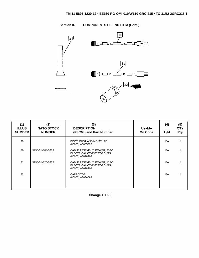
TM 11-5895-1220-12 • EE160-RG-OMI-010/W110-GRC-215 • TO 31R2-2GRC215-1
Section II. COMPONENTS OF END ITEM (Cont.)
(1) (2) (3) (4) (5)ILLUS NATO STOCK DESCRIPTION Usable QTY
NUMBER NUMBER (FSCM ) and Part Number On Code U/M Rqr
29 BOOT, DUST AND MOISTURE EA 1(80063) A3035320
30 5995-01-308-5379 CABLE ASSEMBLY, POWER, 230V EA 1ELECTRICAL CX-13372/GRC-215(80063) A3078203
31 5995-01-326-5355 CABLE ASSEMBLY, POWER, 115V EA 1ELECTRICAL CX-13373/GRC-215(80063) A3078204
32 CAPACITOR EA 1(80063) A3086683
Change 1 C-8

TM 11-5895-1220-12 • EE160-RG-OMI-010/W110-GRC-215 • TO 31R2-2GRC215-1
Section II. COMPONENTS OF END ITEM (Cont.)
(1) (2) (3) (4) (5)ILLUS NATO STOCK DESCRIPTION Usable QTY
NUMBER NUMBER (FSCM ) and Part Number On Code U/M Rqr
33 5995-01-326-0142 Cable Assembly and Reel, EA 1CG-3883/G (80063) A3034219consisting of:
34 Reel, Cable EA 180063) A3034262
35 Cable Assembly, Time of EA 1Day (80063) A3034218
36 Cord Assembly, Shock EA 1(80063) A3034508-1
37 5975-00-878-3791 Rod Assembly, Ground EA 3(81349), MILR11461
38 NOT ASSIGNED Cover, Blackout-Team EA 1Terminal (80063)A3086812
Change 1 C-9

TM 11-5895-1220-12 • EE160-RG-OMI-010/W110-GRC-215 • TO 31R2-2GRC215-1
(1) (2) (3) (4) (5)ILLUS NATO STOCK DESCRIPTION Usable QTY
NUMBER NUMBER (FSCM ) and Part Number On Code U/M Rqr
39 NOT ASSIGNED Cover, Blackout-Remote EA 1I/O Controller (80063)A3034117
40 NOT ASSIGNED Cap, Electrical EA 1(80063) A3172948
Section III. BASIC ISSUE ITEMS
(1) (2) (3) (4)NATIONAL
STOCK DESCRIPTION QTYNUMBER FSCM & PART NUMBER USABLE ON CODE U/I RECM
OPERATOR’S AND UNIT MAINTENANCE EA 1MANUAL FOR RADIO SET AN/GRC-215TM 11-5895-1220-12
Change 2 C-10

TM 11-5895-1220-12 • EE160-RG-OMI-010/W110-GRC215 • TO 31R2-2GRC215-1
APPENDIX DADDITIONAL AUTHORIZATION LIST
Section I. INTRODUCTIOND-1. SCOPE
This appendix lists additional items you are authorized for the support of the Team Terminal.D-2. GENERAL
This list identifies items that do not have to accompany the Team Terminal and that do not have to be turned inwith it. These items are all authorized to you by CTA, MTOE, TDA, or JTA.
D-3. EXPLANATION OF LISTINGNational stock numbers, descriptions, and quantities are provided to help you identify and request the additional
items you require to support this equipment. The items are listed in alphabetical sequence by item name under the typedocument (i.e., CTA, MTOE, TDA, or JTA) which authorizes the item(s) to you. If the item you require differs betweenserial numbers of the same model, effective serial numbers are shown in the last line of the description. If item requireddiffers for different models of this equipment, the model is shown under the "Usable on" heading in the description column.These codes are identified as:
Code Used On
D-1

TM 11-5895-1220-12 • EE160-RG-OMI-010/W110-GRC215 • TO 31R2-2GRC215-1
Section II. ADDITIONAL AUTHORIZATION LIST
(1) (2) (3) (4)NATIONAL
STOCK DESCRIPTION QTYNUMBER FSCM & PART NUMBER USABLE ON CODE U/I AUTH
5810-01-050-2498 BATTERY CASE Z-AKG/TSEC EA 1(98230) ON501300
5810-01-146-3260 COMMUNICATIONS SECURITY EQUIPMENT EA 1TSEC/KG-84(98230) 0N278636
5810-01-236-5245 SPEECH SECURITY EQUIPMENT EA 1TSEC/KY-65A(98230) 0N500902
6130-01-050-9536 POWER SUPPLY, AC/DC Z-AKE/TSEC EA 1(98230) ON501400
5810-01-026-9620 TAPE READER, GENERAL PURPOSE EA 1KOI-18/TSEC(98230) ON190315
5810-01-066-7587 CABLE, FILL (3FT) EA 1(98230) 0N512424 (FUW KOI-18/TSEC)
5820-00-437-2353 CAP, ANTENNA TIP EA 1(80063), SC-C-446180
4020-00-908-6416 ANTENNA TIE-DOWN KIT EA 1(80063), SC-C-208747
Change 1 D-2

TM 11-5895-1220-12 • EE160-RG-OMI-010/W110-GRC215 • TO 31R2-2GRC215-1
APPENDIX E
EXPENDABLE/DURABLE SUPPLIES AND MATERIALS LIST
Section I. INTRODUCTION
E-1. SCOPE
This appendix lists expendable/durable supplies and materials you will need to operate and maintain the TeamTerminal. This listing is for informational purposes only and is not authority to requisition the listed items. These items areauthorized to you by CTA 50-970, Expendable/Durable Items (Except Medical, Class V, Repair Parts, and Heraldic Items),or CTA 8-100, Army Medical Department Expendable/ Durable Items.
E-2. EXPLANATION OF COLUMNS
a. Column(l)- Item number. This number is assigned to the entry in the listing and is referenced in the narrativeinstructions to identify the material (e.g., "Use cleaning compound, item 5, App. E" ).
b. Column(2)- Level. This column identifies the lowest level of maintenance that requires the listed item.
UNIT
C - Operator/CrewO - Organizational/Unit
INTERMEDIATE
F - Direct SupportH - General SupportL - Specialized Repair Activity (SRA)
DEPOT
D - Depot
c. Column(3)- National Stock Number. This is the National stock number assigned to the item; use it to request orrequisition the item.
d. Column(4)- Description. Indicates the Federal item name and, if required, a description to identify the item. Thelast line for each item indicates the Federal Supply Code for Manufacturer (FSCM) in parentheses followed by the partnumber.
E-1

TM 11-5895-1220-12 • EE160-RG-OMI-010/W110-GRC215 • TO 31R2-2GRC215-1
e. Column(5)- Unit of Measure (U/M). Indicates the measure used in performing the actual maintenance function.This measure is expressed by a two-character alphabetical abbreviation (e.g., ea, in, pr). If the unit of measure differs fromthe unit of issue, requisition the lowest unit of issue that will satisfy your requirements.
Section II. EXPENDABLE/DURABLE SUPPLIES AND MATERIALS LIST
(1) (2) (3) (4) (5)
NATIONALITEM STOCK
NUMBER LEVEL NUMBER DESCRIPTION U/M
1 C,O 8305-00-205-3496 CLOTH, COTTON CHEESECLOTH Ea(CCCC 440, 81348)
2 C,O 6340-00-906-3666 BRUSH, SOFT BRISTLED Ea(15335001099)
3 0 6140-01-063-3918 BATTERY, NI-CAD BB-590/U Ea-or-
4 0 6135-01-036-3495 BATTERY BA-5590/U Ea
5 0 6135-00-801-3493 BATTERY BA-1372/U Ea
6 0 5920-00-931-0593 FUSE, CARTRIDGE Ea
7 0 5920-00-938-7660 FUSE, CARTRIDGE Ea
8 0 6340-00-965-1381 LAMP, INCANDESCENT Ea#382 ON501538
Change 1 E-2

TM 11-5895-1220-12 • EE160-RG-OMI-010/W110-GRC215 • TO 31R2-2GRC215-1
APPENDIX F
ERROR, STATUS MESSAGESAND ECCM FAULT CODES
TITLE PAGEERROR AND STATUS MESSAGES .................................................................................................................. F-1ECCM FAULT CODES..................................................................................................................................... F-13ECCM Fault Codes (Group I) .............................................................................................................................. F-15ECCM Fault Codes (Group II) ............................................................................................................................. F-15ECCM Fault Codes (Group II) ............................................................................................................................. F-16ECCM Fault Codes (Group V)............................................................................................................................. F-17ECCM Fault Codes (Group V)............................................................................................................................. F-17ECCM Fault Codes (Group VII)........................................................................................................................... F-18
Following is a list of messages you may see on the D/K assembly. These messages in-form you of errors you have madeentering data, component failures, and the operational status of the I/O Unit. If the message notifies you of a componenterror (these messages end with the word FAULT), note the message, and report it to unit maintenance. Component failuremessages automatically print if the Team Terminal configuration includes a printer. Messages displayed on the status line(second line) remain on the screen until you clear them. To clear a message from the status line, press the CLEAR STATbezel key.
The following Error and Status messages are arranged alphabetically starting with the first letter of the message.For those faults requiring Unit maintenance "action", refer to paragraph 4-11, Unit Troubleshooting Chart.
A PREVIOUS TRANSMIT MESSAGE WAS LOST
Explanation: You transmitted a message when the transmission queue was full. The new message had a higherpriority than one of the other messages in the queue. To make room for the new, higher prioritymessage, the system deleted a lower priority message in the queue.
Action: None. The deleted message cannot be recovered.
ABORT - INVAL KEY
Explanation: While reviewing a message before transmission, you pressed a key that displayed another screenor you pressed the ABORT bezel key. This stopped the transmission sequence.
Action: If you wish to transmit the message, begin the transmission sequence again by recalling the lastedited message on the COMPOSE/EDIT screen (para 2-7c, step 1).
Change 1 F-1

TM 11-5895-1220-12 EE160-RS-OMI-O10/W110-GRC215 TO 31R2-2GRC215-1
ABORT - INVAL MSG
Explanation: You did not perform the steps to transmit a message in the exact sequence specified on thescreen. This aborted the transmission sequence.
Action: Begin the transmission sequence again by recalling the last edited message on COMPOSE/EDITscreen (para 2-7c, step 1).
ABORT - PRIOR MENU
Explanation: By pressing the PRIOR MENU bezel key, you indicated that you wanted to change a messagebefore transmission. This stopped the transmission sequence.
Action: Begin the transmission sequence again by recalling the last edited message on COMPOSE/EDITscreen (para 2-7c, step 1).
ABORT- SEC PARAMS
Explanation: Either the system did not accept the message security parameters or a component failureoccurred.
Action: 1. Press the ABORT bezel key to abort the transmission BIT sequence. Begin the transmissionsequence again by recalling the last edited message on the COMPOSE/EDIT screen (para 2-7c,step 1).
2. If the message appears again, run BIT which will sign you out of the subnet.
3. Report the problem to unit maintenance (para 4-11).
ALL SECRET MSGS PENDING TRANSMIT LOST
Explanation: Team Terminal went from secure mode to nonsecure mode. All secret messages pendingtransmission are automatically deleted from queue.
Action: 1. Tighten connections to TSEC/KG-84A and try to continue.
2. Report the problem to unit maintenance (para 4-11).ATU FAULT
Explanation: The system detected a fault in the ATU. The K/D displays the message FATAL FAULTDETECTED.
Action: 1. Press NEXT MENU to continue to the next menu to perform BIT sequence. Perform the BITsequence as prompted by the K/D display. (para 2-7b STEP 1). All previous entries on the menusremain intact, when the BIT function is completed, the STATUS DISPLAY will indicate SIGN-INPENDING. You will continue to receive messages. You cannot transmit a message until sign-in iscompleted.2. Try to continue operation.
3. Report the problem to unit maintenance (para 4-11).
CAN NOT SIGN OUT- NOT SIGNED IN
Explanation: Appears if you attempt to sign out of the network before the network has recognized and signedyour terminal into the subnet. Any transmit composed/ edited messages awaiting transmission arestill in the queue.
Action: None. Informational message only.
Change 1 F-2

TM 11-5895-1220-12 EE160-RS-OMI-010/W110-GRC215 TO 31R2-2GRC215-1
BLK FAULT - A1A6, A1A7, A1PS1
Explanation: The system detected a fault in the 110 Unit. The K/D displays the message FA-TAL FAULTDETECTED.
Action: 1. Press NEXT MENU to continue to the next menu to perform BIT sequence. Perform the BITsequence as prompted by the K/D display. (para 2-7b STEP I). All previous entries on the menusremain intact, when the BIT function is completed, the STATUS DISPLAY will indicate SIGN-INPENDING. You will continue to receive messages. You cannot transmit a message until sign-in iscompleted.
2. Try to continue operation.
3. Report the problem to unit maintenance (para 4-11).
RED/BLK INTERFACE FAULT-AIA5, AIA6, AIA1A1
Explanation: The system detected a fault in the I/O0 Unit so the terminal cannot control the RT, RN Modem, andRFO. The K/D displays the message FATAL FAULT DE-TECTED
Action: 1. Press NEXT MENU to continue to the next menu to perform BIT sequence. Perform the BITsequence as prompted by the K/D display. (para 2-7b STEP 1). All previous entries on the menusremain intact, when the BIT function is completed, the STATUS DISPLAY will indicate SIGN-INPENDING. You will continue to receive messages. You cannot transmit a message until sign-in iscompleted.
2. Try to continue operation.
3. Report the problem to unit maintenance (para 4- 1).
DISPLAY/KEYPAD BIT FAULT - A2
Explanation: This message appears if you pressed the FAIL touch point during any of the display test screens(para 2-7b, step 1).
Action: 1. Determine if you can continue operating with the fault; that is, decide if the failed area of thedisplay is critical to operation of the I/O Unit
2. Report the problem to unit maintenance (para 4-11).
DISPLAY/KEYPAD INTERFACE FAULT-A1A5
Explanation: The system detected a fault in the interface between the D/K assembly and the processor withinthe controller assembly.
Action: 1. Try to continue operating the O10 Unit. If the D/K assembly responds, continue operation, andreport the fault to unit maintenance.
2. If the D/K assembly does not respond, contact unit maintenance (para 4-11).
Change 1 F-3

TM 11-5895-1220-12 EE160-RS-OMI-010/W110-GRC215 TO 31R2-2GRC215-1
ECCM FAULT
Explanation: The system detected a fault in the ECCM Module. Selecting ECCM or data operating mode beforeloading TRANSEC variables will also cause this fault to appear.
Action: 1. If there is a fault in the ECCM Module, the K/D displays the message FATAL i=’ - FAULTDETECTED. Press NEXT MENU to continue to the next menu to per-form BIT sequence. Allprevious entries on the menus remain intact, when the BIT function is completed, the STATUSDISPLAY will indicate SIGN-IN PENDING. You will continue to receive messages. You cannottransmit a message until sign-in is completed.
o Try to continue operation.
o Report the problem to unit maintenance (para 4-11).
2. If you want to operate in ECCM or data mode, but did not load the TRANS-EC variables, power-off the terminal (para 2-7i) and then power-up the terminal (para 2-7a). Initialize the terminal (para2-7b). Ensure TRANSEC variables load properly (para 2-7b, step 9).
TP/UP INTERFACE FAULT- A1A2, A1A3
Explanation: The system detected a fault in the trusted processor (TP)/untrusted processor (UP) interface withinthe I/O Unit.
Action: 1. Try to continue operation.
2. If the D/K assembly acts abnormally, press the BIT bezel key. If the D/K assembly responds,continue to operate.
3. If the D/K assembly does not respond, the unit cannot operate normally. Re-’ port the problemto unit maintenance (para 4-11).
GO
Explanation: Team Terminal ready for operation.
Action: None.
HIGH SPEED SYNTHESIZER FAULT
Explanation: The system detected a fault in the high speed synthesizer contained in the Vehicular Adapter. TheK/D displays the message FATAL- FAULT DETEC’T’ED.
Action: 1. Press NEXT MENU to continue to the next menu to perform BIT sequence. Perform the BITsequence as prompted by the K/D display. (para 2-7b STEP 1). All previous entries on the menusremain intact, when the BIT function is completed, the STATUS DISPLAY will indicate SIGN-INPENDING. You will continue to receive messages. You cannot transmit a message until sign-in iscompleted.
2. Try to continue operation.
3. Report the problem to unit maintenance (para 4-11).’
Change 1 F-4

TM 11-5895-1220-12 EE160-RS-OMI-010/W110-GRC215 TO 31R2-2GRC215-1
INCORRECT FREQ CODES -NET LINK LOST
Explanation: The frequency codes you selected do not match the ones your subnet controller is using. Eitheryou made an error entering the data or you missed an update that the controller issued.
Action: 1. Check your COMMUNICATIONS ELECTRONICS OPERATOR INSTRUC-TIONS Handbook tobe sure you entered the correct frequency codes.
2. If you entered the correct frequency codes, the controller updated the data and your terminalfailed to receive the message. Try to contact the controller operator for current subnet frequencycodes.
RED INTERFACE CARD FAULT- A1A5
Explanation: The system detected a fault within the I/O Unit. The K/D displays the message FATAL FAULTDETECTED.
Action: 1. Press NEXT MENU to continue to the next menu to perform BIT sequence. Perform the BITsequence as prompted by the K/D display. (para 2-7b STEP 1). All previous entries on the menusremain intact, when the BIT function is completed, the STATUS DISPLAY will indicate SIGN-INPENDING. You will continue to receive messages. You cannot transmit a message until sign-in iscompleted.
2. Try to continue operation.
3. If the D/K assembly acts abnormally, press the BIT bezel key. If the D/K assembly responds,continue to operate.
4. If the D/K assembly does not respond, the unit cannot operate normally. Re-port the problem tounit maintenance (para 4-11).
INVALID FIELD ENTRY
Explanation: You entered data out of the required range (e.g., XX if the range was AA to TR), the wrong type ofdata (e.g., alpha when numeric was required), or pressed a key before you entered the requireddata for the menu.
Action: Re-enter the data.
INVALID KEY
Explanation: This can appear on any menu except the transmission sequence menus. It means you pressed akey that is inactive for the current menu.
Action: Follow the instructions on the menu to determine which keys are valid.
KG-84A FAULT
Explanation: The system detected a fault in the TSEC/KG-84A or you did not load TSEC/ KG-84A cryptographicvariables.
Action: 1. If you are operating in the secure data mode, TSEC/KG-84A cryptographic variables must beloaded. Power-off the Team Terminal and then re-initialize the Team Terminal for secure datamode (para 2-7b).
Change 1 F-5

TM 11-5895-1220-12 EE160-RS-OMI-010/W110-GRC215 TO 31R2-2GRC215-1
o Secure operations require the TSEC/KG-84A to be operational. If you do not need tooperate in the secure mode, remove TSEC/KG-84A and hookup KG-84A nonsecure bypassassembly (para 2-5a(3)). The receiving terminal must also be operating without a TSEC/KG-84A.
o Report the problem to unit maintenance (para 4-11).
KG-84A INTERFACE FAULT - A1A5
Explanation: The system detected a fault in the TSEC/KG-84A data link to the network. The K/D displays themessage FATAL FAULT DETECTED.
Action: 1. Press NEXT MENU to continue to the next menu to perfona BIT sequence. Perform the BITsequence as prompted by the K/D display. (para 2-7b STEP 1). All previous entries on the menusremain intact, when the BIT function is completed, the STATUS DISPLAY will indicate SIGN-INPENDING. You will continue to receive messages. You cannot transmit a message until sign-in iscompleted.
2. Try to continue operating the I/O Unit.
3. If the D/K assembly does not respond, press the BIT bezel key (this will cause your I/O Unit toleave the network). Perform the steps to run the BIT and sign into the network again (para 2-7b).
4. Report the problem to unit maintenance (para 4-11).
MESSAGE # XXX QUEUED FOR TRANSMISSION
Explanation: Appears at the end of the transmission sequence. All the necessary steps to transmit a messagewere completed and the message is in queue, waiting to be re-leased by the system.
Action: None. Informational only.
MSG XXX OVERWRITTEN
Explanation: A new message was added to the transmission queue when the queue was full. The newmessage had a higher priority than one of messages in the queue. To make room for the newhigher priority message, the system deleted a lower priority message in the queue.
Action: None. Informational only.
NET CONNECTION LOST-SIGN IN PENDING
Explanation: Communication was lost with your terminal controller. Your terminal automatically tries to restorecommunication with the controller.
Action: Until your terminal re-establishes communication with the controller, you can only performoperations not requiring communication with the network (e.g., composing and editing messages).To help re-establish communications, select a higher power level on the TRANSMITTER POWERLEVEL menu. Return to the TRANSMITTER LEVEL menu using the operational set up mode (para2-7e).
Change 1 F-6

TM 11-5895-1220-12 EE160-RS-OMI-010/W110-GRC215 TO 31R2-2GRC215-1
NET OPERATIONAL CHANGES PENDING
Explanation: Indicates that your terminal controller is changing the operational parameters of your I/O Unit (e.g.,mode, frequencies).
Action: None. The changes occur automatically. You may wish to determine the changes made byaccessing the SET UP Menu (para 2-7e) and then selecting one of the initialization menus. Theinitialization menus appear with the new settings displayed.
NETWORK SIGN IN PENDING
Explanation: You pressed the NEXT MENU bezel key on the SIGNING INTO THE SUBNET screen. Thismessage appears to notify you that the system has not yet signed your I/O Unit into the network.
Action: None. You may compose and edit messages until the SIGNED INTO NETWORK messageappears, notifying you that your I/O unit is signed into the network.
NO 10KHZ AT ECCM FAULT
Explanation: The system detected continuity problem with the 10 kHz signal. The BIT sequence menu appears,to begin running BIT, answer prompts.
Action: 1. Tighten cables W203 and W205. Perform BIT again.2. Report the problem to unit maintenance (para 4-11).
NO GO
Explanation: Appears when BIT is running.
Action: None.
NO RESPONSE FROM ECCM FAULT
Explanation: The ECCM Module is not responding to commands from the I/O Unit.
Action: 1. Check to ensure that ECCM Module is powered-up and that fill device is not connected to FILLconnector on ECCM Module.
2. Report the problem to unit maintenance (para 4-11).
NON SECURE MODE- SECRET MSG, NOT QUEUED
Explanation: TSEC/KG-84A is not connected or is inoperative. Secret message is not queued for transmit.
Action: 1. Inspect for proper installation of TSEC/KG-84A (para 2-5a(2)).
2. Tighten connections to TSEC/KG-84A and try to continue.
3. Report the problem to unit maintenance (para 4-11).
Change 1 F-7

TM 11-5895-1220-12 EE160-RS-OMI-010/W110-GRC215 TO 31R2-2GRC215-1
NON-SECURE
Explanation: Team Terminal configured for nonsecure data operations.
Action: None.PA FAULT
Explanation: The system detected a fault in the PA. The K/D displays the message FATAL FAULT DETECTED.
Action: 1. Press NEXT MENU to continue to the next menu to perform BIT sequence. All previous entrieson the menus remain intact, when the BIT function is completed, the STATUS DISPLAY willindicate SIGN-IN PENDING. You will continue to receive messages. You cannot transmit amessage until sign-in is completed.
2. Try to continue operation.
3. Report the problem to unit maintenance (para 4-11).
POWER SUPPLY FAULT - A1PS1
Explanation: The system detected a fault in the I/O Unit power supply.
Action: 1. Try to continue operation.
2. Report the problem to unit maintenance (para 4-11).
PRESS A TOUCHPOINT
Explanation: This is an informational message. It appears on the MESSAGE SECURITY menu (para 2-7c step6) to tell you that you must first select message priority and classification before pressing any bezelkey.
Action: Press one of the touchpoints to make your selection.
PRINTER NOT OPERATIONAL
Explanation: Either a printer is not connected to the I/O Unit, or the terminal detected a fault in the printer,connectors, or lines.
Action: 1. If a printer is present, check to be sure it is powered- on. Also check the connectors and line 2.If the printer, connectors, and lines appear operational, continue operation and report the problemto unit maintenance (para 4-11).
PTR DSBL
Explanation: Printer disabled.
Action: None.
PTR ENBL
Explanation: Printer enabled.
Action: None.
Change 1 F-8

TM 11-5895-1220-12 EE160-RS-OMI-010/W110-GRC215 TO 31R2-2GRC215-1
RECEIVE MESSAGE QUEUE NEARLY FULL
Explanation: Appears when the total number of received messages (read and unread) in message queuereaches about 75 percent of the queue’s capacity.
Action: 1. Press the SHOW MSG key to see the messages in the queue. Delete messages that need notremain in queue (para 2- 7d).
2. I f you do not delete messages in the queue, the system deletes overflow messages. It keepsthe highest precedence messages first, followed by the latest received messages.
RECEIVER/EXCITER FAULT
Explanation: The system detected a fault in the R/E. The K/D displays the message FATAL FAULTDETECTED.
Action: 1. Press NEXT MENU to continue to the next menu to perform BIT sequence. All previous entrieson the menus remain intact, when the BIT function is completed, the STATUS DISPLAY willindicate SIGN-IN PENDING. You will continue to receive messages. You cannot transmit amessage until sign-in is completed.
2. Try to continue operation.
3. Report the problem to unit maintenance (para 4-11).RECEIVER/EXCITER PA FAULT
Explanation: The system detected a fault in the PA contained in the R/E.
Action: 1. The BIT sequence menu appears, to begin running BIT, answer prompts. Your previous entrieson the menus remain intact.
2. Try to continue operation.
3. Report the problem to unit maintenance (para 4-11).
RFO FAULT
Explanation: The system detected a fault in the RFO. The K/D displays the message FATAL FAULTDETECTED.
Action: 1. Press NEXT MENU to continue to the next menu to perform BIT sequence. All previous entrieson the menus remain intact, when the BIT function is completed, the STATUS DISPLAY willindicate SIGN-IN PENDING. You will continue to receive messages. You cannot transmit amessage until sign-in is completed.
2. Try to continue operation.
3. Report the problem to unit maintenance (para 4-11).
RFO HAS NEW TIME
Explanation: The RFO has received a new TOD.
Action: Press NEXT MENU to continue to the next menu to perform BIT sequence. All previous entries onthe menus remain intact, when the BIT function is completed, the STATUS DISPLAY will indicateSIGN-IN PENDING. You will continue to receive messages. You cannot transmit a message untilsign-in is completed.
Change 1 F-9

TM 11-5895-1220-12 EE160-RS-OMI-010/W110-GRC215 TO 31R2-2GRC215-1
RN MODEM FAULT
Explanation: The system detected a fault in the RN Modem. The K/D displays the message FA-TAL FAULTDETECTED.
Action: 1. Press NEXT MENU to continue to the next menu to perform BIT sequence. All previous entrieson the menus remain intact, wheh the BIT function is completed, the STATUS DISPLAY willindicate SIGN-IN PENDING. You will continue to receive messages. You cannot transmit amessage until sign-in is completed.
2. Try to continue operation.
3. Report the problem to unit maintenance (para 4-11).
ROLLED TO END
Explanation: On the REVIEW MESSAGE screen (para 2-7c, step 5) or the SHOW MESSAGE screen (para 2-7d, step 2), you pressed the ROLL UP bezel key until the end of the message was displayed.
Action: Continue operation. Follow instructions on the screen.
ROLLED TO TOP
Explanation: On the REVIEW MESSAGE screen (para 2-7c, step 5) or the SHOW MESSAGE screen (para 2-7d, step 2), you pressed the ROLL DOWN bezel key until the top of the message was displayed.
Action: Press the ROLL UP bezel key to review the message or follow the instructions on the screen.
SECURE
Explanation: Team Terminal configured for secure data operations.
Action: None.
SIGNED INTO NETWORK
Explanation: Appears when your I/O Unit is recognized and signed into the subnet.
Action: None. Informs you that your I/O Unit can now communicate with the subnet you specified on theSUBNET NUMBER menu (para 2-7b, step 34).
SIGNED OUT OF NETWORK
Explanation: Appears on the LEAVE NET menu after the NETWORK SIGN OUT PENDING message. Youpressed NEXT MENU bezel key on the LEAVE NET menu and received the pending message untilthe system signed out your I/O Unit from the network. Then the SIGNED OUT OF NETWORKmessage appeared to inform you that your I/O Unit stopped communications with network.
Action: None. Information only. The I/O Unit can be powered-off without losing transmit messages.
Change 1 F-10

TM 11-5895-1220-12 EE160-RS-OMI-010/W110-GRC215 TO 31R2-2GRC215-1
THIS TRANSMIT MESSAGE WAS NOT QUEUED
Explanation: You tried to add a message to a full transmission queue and the new message has a lower orsame priority than the messages in the queue; therefore, the message was not added.
Action: Wait for the transmission queue to empty by periodically trying to add the message to the queue.
TP FIFO BIT FAULT - A1A3
Explanation: The system detected a fault in the TP first-in-firstout (FIFO) circuit within the 1/0 Unit.
Action: 1. Try to continue operation.
2. If the D/K assembly acts abnormally, press the BIT bezel key. If the D/K assembly responds,perform the initialization steps again and sign into the network (para 2-7b). Your previous entrieson the menus remain intact and are displayed again, so that all you need to do is verify them. If theD/K assembly does not respond, the unit cannot operate normally.
3. Report the problem to unit maintenance (para 4-11).
TRANSMIT MESSAGE ON QUEUE
Explanation: Appears at the end of the transmission sequence. You completed all the necessary steps totransmit a message and the message is in queue, waiting to be released by the system.
Action: None. Informational only.
TTIO TO CIU MESSAGE OVERFLOW FAULT
Explanation: The system detected a fault in the message transfer interface between the Team Terminal (TT)Input/Output (I/O) and the Control Interface Unit (CIU).
Action: 1. Press the [BIT] bezel key. The Built-In Test (BIT) sequence begins and the PERFORMDISPLAY/KEYPAD TEST screen appears.
2. After BIT has completed, perform the initialization steps required to sign into network. Theprevious menu entries remain intact.
3. Report the problem to unit maintenance (para 4-1 1).
UP BIT FAULT- A1A2
Explanation: The system detected a fault in the untrusted processor (UP) contained in the I/O Unit.
Action: 1. Try to continue operation.
2. If the D/K assembly acts abnormally, press the BIT bezel key. Perform the initialization stepsagain and sign into the network (para 2-7b). Your previous en-tries on the menus remain intact andare displayed again, so that all you need to do is verify them.
3. Report the problem to unit maintenance (para 4-11).
Change 1 F-11

TM 11-5895-1220-12 EE160-RS-OMI-010/W110-GRC215 TO 31R2-2GRC215-1
UP FIFO ISIT FAULT-A1A2
Explanation: The system detected a fault in the UP contained in the I/O Unit.
Action: 1. Try to continue operation.
2. If the D/K assembly acts abnormally, press the BIT bezel key. If the D/K assembly responds,perform the initialization steps again and sign into the network W (para 2-7b). Your previousentries on the menus remain intact and are displayed again, so that all you need to do is verifythem. If the D/K assembly does not respond, the unit cannot operate normally.
3. Report the problem to unit maintenance (para 4-11).
WRONG KEY FOR MENU
Explanation: This message could appear on any screen during the transmission sequence. It means that youpressed a key other than the one required in the sequence, but transmission was not aborted.
Action: Follow the instructions on the menu.
-A2 REV 004- UNTRUSTED PROCESSOR
Explanation: Indicates the version of operational software running in the terminal at this time.
Action: None. Informational only.
-A3 REV 004- TRUSTED PROCESSOR
Explanation: Indicates the version of operational software running in the terminal at this time.
Action: None. Informational only.
Change 1 F-12

TM 11-5895-1220-12 EE160-RS-OMI-010/W110-GRC215 TO 31R2-2GRC215-1
ECCM FAULT CODE TABLES
TABLE TITLE PAGEECCM FAULT CODE TABLES
F-1 ECCM Fault Codes (Group I) ................................................................................................................ F-15F-2 ECCM Fault Codes (Group II) ............................................................................................................... F-15F-3 ECCM Fault Codes (Group III) .............................................................................................................. F-16F-4 ECCM Fault Codes (Group IV).............................................................................................................. F-17F-5 ECCM Fault Codes (Group V)............................................................................................................... F-17F-6 ECCM Fault Codes (Group VII)............................................................................................................. F-18
The following ECCM fault codes are those that can appear on the ECCM front panel display should a fault occur.When the ECCM module shows "FAILED", press the ENT/IST key and the error code will be displayed.
NOTE
The recommended course of "action" for each ECCM error code has been abbreviation for these tables. Refer to the UnitTroubleshooting Chart para 4-11, item 23, for detailed troubleshooting procedures.
Change 1 F-13

TM 11-5895-1220-12 EE160-RS-OMI-010/W110-GRC215 TO 31R2-2GRC215-1
The following abbreviations are used in the tables:
• ATU Antenna Tuning Unit• BIT Built-In Test• BLK Black• CIU Control Interface Unit• CUP Crypto Microprocessor• DK Display/KeyPad• ECCM Electronic Counter-Counter Measures• FIFO First In/First Out• FREQ Frequency• FT Force Terminal• HSS High-Speed Synthesizer• INVAL Invalid• KG Refers to the TSEC/KG-84A device• LSG Linear Sequence Generator• MP Manpack• MSG Message• MUP Main Microprocessor• NET Network• PA PowerAmplifier• PARAMS Parameters• P/P S Pre/Post Selector• PS Power Supply• PUP Peripheral Microprocessor• RAM Random Access Memory• RFO Reference Frequency Oscillator• ROM Read-Only Memory• SEC Security• TOD Time-of-day• TP Trusted Processor• TT Team Terminal• UP Untrusted Processor• USART Universal Synchronous/Asynchronous Receiver-Transmitter• VA Vehicular Adapter
Change 1 F-14

TM 11-5895-1220-12 EE160-RS-OMI-010/W110-GRC215 TO 31R2-2GRC215-1
The codes in Table F-1 appear when equipment other than the Electronic Counter--- Counter- Measures (ECCM) or radiois faulted. Before replacing units, run BIT to clear the problem.
Table F-1. ECCM Fault Codes (Group I)
ModeECCM Explanation After ActionCode Fault
01 PA has a fault N/A Run BIT. Check cables. Replace PA.
02 ATU has a fault N/A Run BIT. Check cables. Replace ATU.03 - 09 Reserved
*NOTE: Only replace equipment if BIT does not clear problem.
The codes in Table F-2 appear when operational faults occur. Operational faults result from improperly installedequipment or procedural errors. Recheck connections and try to continue operations.
Table F-2. ECCM Fault Codes (Group II)
ModeECCM Explanation After Action
Code Fault
10 Invalid attempt to change to data Voice Check cables and modem connections.mode. System thinks modem is Retry.not attached.
11 Invalid mode change without a Voice Fill the ECCM. Retry.variable.
12 Invalid mode change without a Voice Supply valid TOD to ECCM. Retry.TOD.
13 Invalid mode change in MP config- Voice MP only allowed Voice modes. Retry.uration.
14 Invalid cryptovarible change re- N/A Remove fill device. Retry.quest.
15 Fill in Progress. Successful fill.
16 Zeroize Command. Successful zeroize.
17 Modem or HSS disconnect during Voice Check modem to ECCM connectiondata mode operation. (FT/TT). Check ECCM to VA Connection
(TT).
18-19 Reserved
Change 1 F-15

TM 11-5895-1220-12 EE160-RS-OMI-010/W110-GRC215 TO 31R2-2GRC215-1
The codes in Table F-3 appear when ECCM hardware faults occur. If running BIT does not clear the problem,replace the unit.
Table F-3. ECCM Fault Codes (Group I)
ModeECCM Explanation After Action
Code Fault
20 Internal ECCM communication N/A Cycle R/E power off/on. Reload variables.fault (MUP/PUP) Run BIT. Replace ECCM.
21 CUP RAM fault N/A Run BYT Replace ECCM.
22 CUP ROM checksum fault N/A Run BIT. Replace ECCM.23 Internal ECCM communication Voice Run BIT- Replace ECCM.
fault (MUP/CUP)24 Internal ECCM communication Voice Run BIT. Replace ECCM.
Timeout
25 Internal audio fault N/A Run BIT. Replace ECCM.26 MUP RAM fault N/A Run BIT. Replace ECCM.
27 MUP ROM checksum fault N/A Run BIT. Replace ECCM.28 PUP RAM fault N/A Run BIT. Replace ECCM.
29 PUP ROM checksum fault N/A Run BIT. Replace ECCM.30 Modem USART fault N/A Run BIT. Replace ECCM.
31 CIU USART fault N/A Run BIT. Replace ECCM.32 Low Battery indicator (MP only) N/A Notify MMCT to replace batteries. Reload
variables.
*NOTE: Only replace equipment if BIT does not clear problem.
Change 1 F-16
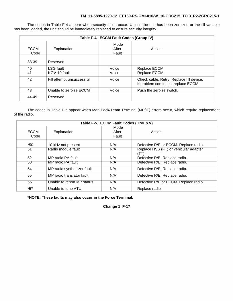
TM 11-5895-1220-12 EE160-RS-OMI-010/W110-GRC215 TO 31R2-2GRC215-1
The codes in Table F-4 appear when security faults occur. Unless the unit has been zeroized or the fill variablehas been loaded, the unit should be immediately replaced to ensure security integrity.
Table F-4. ECCM Fault Codes (Group IV)
ModeECCM Explanation After Action
Code Fault
33-39 Reserved
40 LSG fault Voice Replace ECCM.41 KGV-10 fault Voice Replace ECCM.
42 Fill attempt unsuccessful Voice Check cable. Retry. Replace fill device.If problem continues, replace ECCM
43 Unable to zeroize ECCM Voice Push the zeroize switch.
44-49 Reserved
The codes in Table F-5 appear when Man Pack/Team Terminal (MP/IT) errors occur, which require replacementof the radio.
Table F-5. ECCM Fault Codes (Group V)Mode
ECCM Explanation After ActionCode Fault
*50 10 kHz not present N/A Defective R/E or ECCM. Replace radio.51 Radio module fault N/A Replace HSS (FT) or vehicular adapter
(TT).52 MP radio PA fault N/A Defective R/E. Replace radio.53 MP radio PA fault N/A Defective R/E. Replace radio.
54 MP radio synthesizer fault N/A Defective R/E. Replace radio.
55 MP radio translator fault N/A Defective R/E. Replace radio.
56 Unable to report MP status N/A Defective R/E or ECCM. Replace radio.
*57 Unable to tune ATU N/A Replace radio.
*NOTE: These faults may also occur in the Force Terminal.
Change 1 F-17
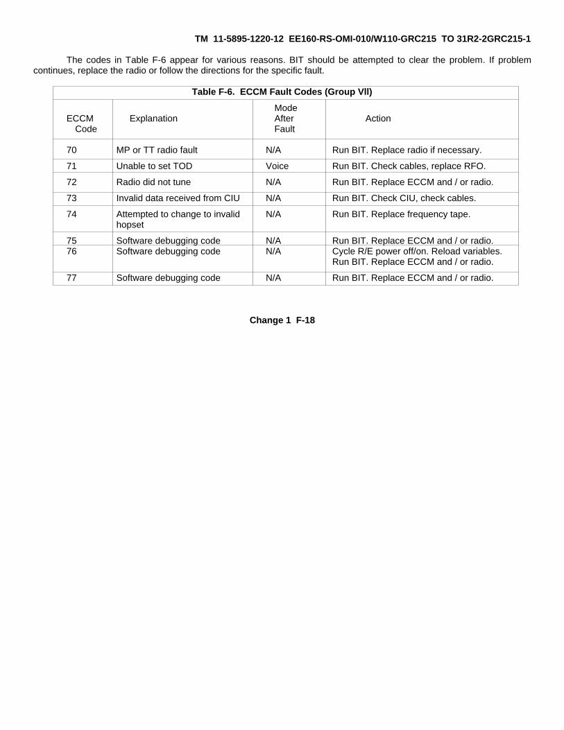
TM 11-5895-1220-12 EE160-RS-OMI-010/W110-GRC215 TO 31R2-2GRC215-1
The codes in Table F-6 appear for various reasons. BIT should be attempted to clear the problem. If problemcontinues, replace the radio or follow the directions for the specific fault.
Table F-6. ECCM Fault Codes (Group Vll)
ModeECCM Explanation After Action
Code Fault
70 MP or TT radio fault N/A Run BIT. Replace radio if necessary.
71 Unable to set TOD Voice Run BIT. Check cables, replace RFO.
72 Radio did not tune N/A Run BIT. Replace ECCM and / or radio.
73 Invalid data received from CIU N/A Run BIT. Check CIU, check cables.
74 Attempted to change to invalid N/A Run BIT. Replace frequency tape.hopset
75 Software debugging code N/A Run BIT. Replace ECCM and / or radio.76 Software debugging code N/A Cycle R/E power off/on. Reload variables.
Run BIT. Replace ECCM and / or radio.
77 Software debugging code N/A Run BIT. Replace ECCM and / or radio.
Change 1 F-18

TM 11-5895-1220-12 • EE160-RS-OMI-010/W110-GRC215 • TO 31R2-2GRC215-1
GLOSSARY
Section I. ABBREVIATIONS
AAAL......................................................................................................................................... Additional Authorization ListAC......................................................................................................................................................... Alternating CurrentATU ....................................................................................................................................................Antenna Tuning Unit
BBAT CHG ................................................................................................................................................... Battery ChargeBAT TEST ....................................................................................................................................................... Battery TestBII ........................................................................................................................................................... Basic Issue ItemsBIT ....................................................................................................................................................................Built In TestBITE............................................................................................................................................... Built In Test EquipmentBTRY INSTLD ...........................................................................................................................................Battery Installed
CCBR........................................................................................................................Chemical, Biological, and RadiologicalCCA.................................................................................................................................................Circuit Card AssemblyCEOI..................................................................................................Communications Electronics Operating InstructionsCHGR.....................................................................................................................................................................ChargerCIU ....................................................................................................................................................Control Interface UnitCOEI............................................................................................................................................Components of End ItemCOMSEC....................................................................................................................................Communications SecurityCONT ..................................................................................................................................................................ControllerCLR ............................................................................................................................................................................ClearCTN ......................................................................................................................................................... Continuous Tone
DDC ................................................................................................................................................................ Direct CurrentDEL........................................................................................................................................................................... DeleteDIP............................................................................................................................................................................ DipoleDISREP ........................................................................................................................................................................................................................................................................................................................Discrepancy in Shipment ReportD/K..............................................................................................................................................................Display/KeypadDSBL .......................................................................................................................................................................DisableDSPL ....................................................................................................................................................................................................................................................................................................................................................................Display
EECCM......................................................................................................................Electronic Counter-CountermeasuresEIR................................................................................................................Equipment Improvement RecommendationsEMERG ............................................................................................................................................................ EmergencyEMP.................................................................................................................................................Electromagnetic PulseENBL ....................................................................................................................................................................... EnableENT ............................................................................................................................................................................EnterESD ................................................................................................................................................Electrostatic Discharge
GLOSSARY-1

TM 11-5895-1220-12 • EE160-RS-OMI-010/W110-GRC215 • TO 31R2-2GRC215-1
E (Cont.)EXT BAT ................................................................................................................................................... External BatteryEXT POWER.............................................................................................................................................. External Power
FFAST SYNTH ...........................................................................................................................................Fast SynthesizerFIFO ......................................................................................................................................................... First-In-First-OutFREQ..................................................................................................................................................................FrequencyFREQ STAND .................................................................................................................................... Frequency StandardFSCM ......................................................................................................................Federal Supply Code for ManufactureFSK..................................................................................................................................................Frequency Shift Key C
GGND.........................................................................................................................................................................GroundGRD.........................................................................................................................................................................GroundHHF.............................................................................................................................................................. High FrequencyHPR.................................................................................................................................................................. High PowerHR .................................................................................................................................................................Hand ReceiptHW ...................................................................................................................................................................Hard-WiredHz ............................................................................................................................................................................... Hertz
I
IAW...................................................................................................................................................... In Accordance WithID.................................................................................................................................................................... IdentificationINSRT.........................................................................................................................................................................InsertINTFC....................................................................................................................................................................InterfaceINVAL ....................................................................................................................................................................... InvalidI/O....................................................................................................................................................................Input/Output
LLOD .............................................................................................................................................................................LoadLPR....................................................................................................................................................................Low PowerLRU ................................................................................................................................................. Line Replaceable UnitLSB............................................................................................................................................................Lower Sideband
MMAC......................................................................................................................................Maintenance Allocation ChartMC..................................................................................................................................................... Maintenance ControlMDCS.................................................................................................................Maintenance Data Collection SubsystemMHz ....................................................................................................................................................................MegahertzMODEM.........................................................................................................................................Modulator/DemodulatorMMCT..........................................................................................................................Mobile Maintenance Contact TeamMP ........................................................................................................................................................................ManpackMPR.............................................................................................................................................................Medium Power
GLOSSARY - 2

TM 11-5895-1220-12 • EE160-RS-OMI-010/W110-GRC215 • TO 31R2-2GRC215-1
M (Cont.)MSG .....................................................................................................................................................................MessageMWO .......................................................................................................................................... Maintenance Work Order
NNBC...............................................................................................................................Nuclear, Biological, and ChemicalNCS...............................................................................................................................................Network Control StationNET ....................................................................................................................................................................... NetworkNI .............................................................................................................................................................. Numerical IndexNSN............................................................................................................................................... National Stock NumberNVIS ...............................................................................................................Near Vertical Incidence Skywave (antenna)
0OSC......................................................................................................................................................................Oscillator
PPA.............................................................................................................................................................. Power AmplifierPARAMS ..........................................................................................................................................................ParametersPMCS ........................................................................................................ Preventive Maintenance Checks and ServicesPST........................................................................................................................................................................... PresetPTR ..........................................................................................................................................................................PrinterPTT.................................................................................................................................................. Push-To-Talk (switch)PWR ......................................................................................................................................................................... PowerPWR/SIG....................................................................................................................................................... Power/SignalPWR SUP......................................................................................................................................................Power Supply
RRCS.....................................................................................................................................................Remote Control SetR/E.............................................................................................................................................................Receiver/exciterRF............................................................................................................................................................ Radio FrequencyRFO..................................................................................................................................Reference Frequency OscillatorRN ..................................................................................................................................................................Regency NetROD.................................................................................................................................................Report of DiscrepancyRT......................................................................................................................................................Receiver-TransmitterRX...........................................................................................................................................................................Receive
SSALT....................................................................................................................................Satellite Action Logic TransferSB........................................................................................................................................................................ SidebandSPAC........................................................................................................................................................................ SpaceSSB .......................................................................................................................................................... Single SidebandSTAT ........................................................................................................................................................................ StatusSYNC...............................................................................................................................................................Synchronize
GLOSSARY - 3

TM 11-5895-1220-12 • EE160-RS-OMI-010/W110-GRC215 • TO 31R2-2GRC215-1
TTEL.....................................................................................................................................................................TelephoneTMDE ...................................................................................................... Test, Measurement, and Diagnostic EquipmentTOD................................................................................................................................................................. Time of DayTP..........................................................................................................................................................Trusted ProcessorTRANS .................................................................................................................................................................. TransferTRANSEC ....................................................................................................................................... Transmission SecurityTST...............................................................................................................................................................................TestTT PS .................................................................................................................................. Team Terminal Power SupplyTUN ............................................................................................................................................................................ TuneTX......................................................................................................................................................................... Transmit
UU/M.................................................................................................................................................... Unit of MeasurementUNBAL............................................................................................................................................................. UnbalancedUP.......................................................................................................................................................Untrusted ProcessorUSB ...........................................................................................................................................................Upper Sideband
VVAR ....................................................................................................................................................................... VariableVEH ADPTR...........................................................................................................................................Vehicular AdapterVOL ........................................................................................................................................................................ VolumeVSWR.................................................................................................................................. Voltage Standing Wave Ratio
X
XMT...................................................................................................................................................................... Transmit
Section II. DEFINITION OF UNUSUAL TERMS
ABORT - To cut short or break off an action, operation, or procedure.
AUDIO - Frequencies which can be heard by the human ear, usually between 15 Hz and 20 kHz.
COLD START - Bringing the system into operation by applying power and performing all initialization procedures.’COMSEC EQUIPMENT - Communication Security Equipment TSEC/KG-84A or TSEC/KY-65 used forencryption/decryption of messages.
DEMODULATE - To recover the wave with which the carrier was originally modulated.
FREQUENCY SHIFT KEYING (FSK) - A form of frequency modulation in which the modulating wave shifts the outputfrequency between predetermined values.
HERTZ - A unit of frequency equal to one cycle per second.
GLOSSARY-4

TM 11-5895-1220-12 • EE160-RS-OMI-010/W110-GRC215 • TO 31R2-2GRC215-1
INITIALIZE - To set up, or adjust, an electronic device for its basic initial operating mode.
INTERFACE - A device or equipment making possible inter-operation between two circuits or systems.
KEEP-ALIVE VOLTAGE - A dc voltage that maintains a circuit during short-term power interruptions.
MANPACK - Man-portable equipment set.
MODE - A particular functional arrangement or condition, i.e., receive mode which sets up circuits into particular conditionsto receive as opposed to transmit mode which arranges functional circuits into different conditions.
MODEM - Modulator/demodulator. A device that modulates and demodulates signals transmitted over communicationscircuits.
MODULATE - To vary the amplitude or frequency of a wave by impressing one wave on another wave.
ON-LINE BACKGROUND SELF-TEST - Automatic self-testing of the system which takes place while the system ispowered-up.
PROPAGATION - The travel of electromagnetic waves between two points.
QUEUE - A list of messages waiting for service (waiting to be read and/or transmitted).
REAL-TIME CLOCK - A clock that indicates the passage of actual time.
SKIP ZONE - An inherent characteristic of radio-wave propagation, using whip antennas. It is the point where the ground-wave signal becomes unusable and the skywave signal starts to become usable.
SKYWAVE - Radio-waves effected by the earth’s outer atmosphere.
SYNTHESIZER - A device that can generate a number of frequencies for multichannel communications equipment.
TOUCHPOINT - Transparent touch-activated switches located on the D/K assembly.
TRICHLOROTRIFLUOROETHANE - A cleaning solution.
GLOSSARY 5/ (GLOSSARY -6 blank)
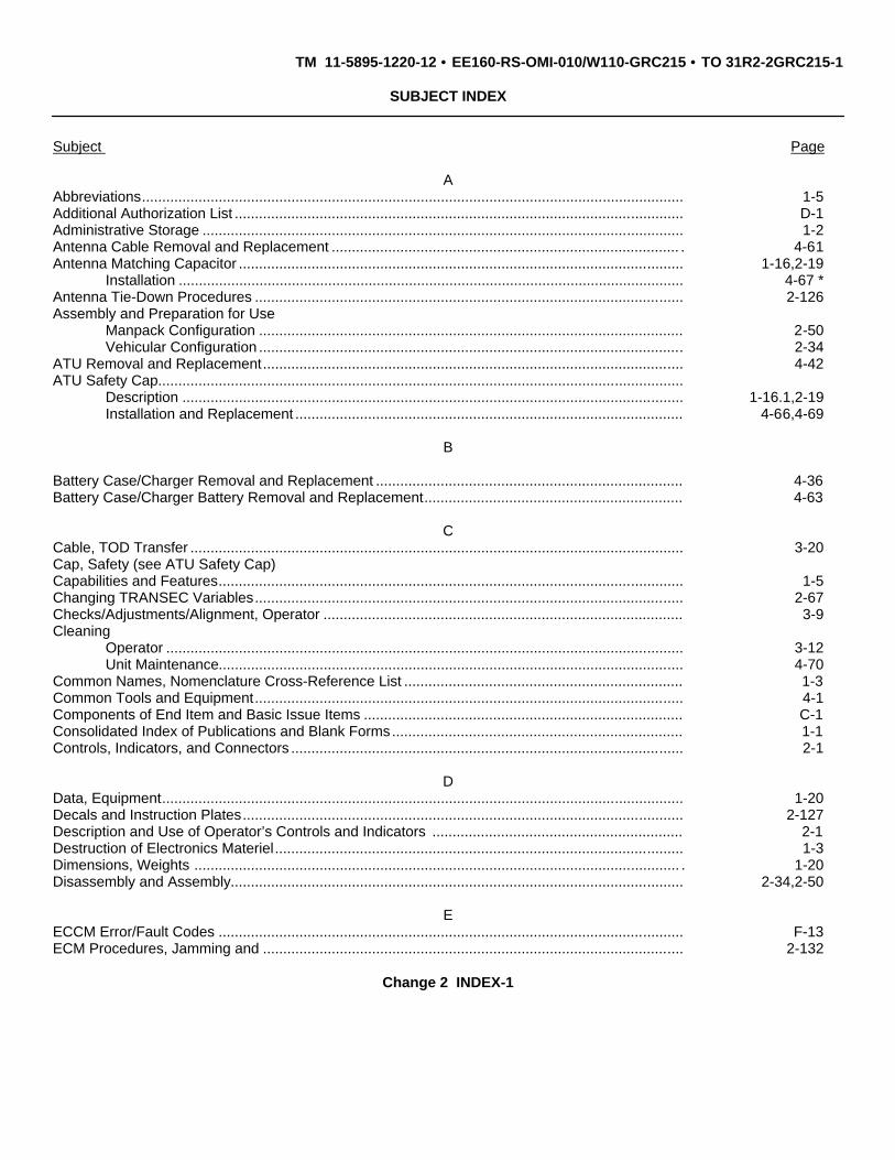
TM 11-5895-1220-12 • EE160-RS-OMI-010/W110-GRC215 • TO 31R2-2GRC215-1
SUBJECT INDEX
Subject Page
AAbbreviations...................................................................................................................................... 1-5Additional Authorization List ............................................................................................................... D-1Administrative Storage ....................................................................................................................... 1-2Antenna Cable Removal and Replacement ...................................................................................... . 4-61Antenna Matching Capacitor .............................................................................................................. 1-16,2-19
Installation ............................................................................................................................. 4-67 *Antenna Tie-Down Procedures .......................................................................................................... 2-126Assembly and Preparation for Use
Manpack Configuration ......................................................................................................... 2-50Vehicular Configuration ......................................................................................................... 2-34
ATU Removal and Replacement........................................................................................................ 4-42ATU Safety Cap..................................................................................................................................
Description ............................................................................................................................ 1-16.1,2-19Installation and Replacement ................................................................................................ 4-66,4-69
B
Battery Case/Charger Removal and Replacement ............................................................................ 4-36Battery Case/Charger Battery Removal and Replacement................................................................ 4-63
CCable, TOD Transfer .......................................................................................................................... 3-20Cap, Safety (see ATU Safety Cap)Capabilities and Features................................................................................................................... 1-5Changing TRANSEC Variables.......................................................................................................... 2-67Checks/Adjustments/Alignment, Operator ......................................................................................... 3-9Cleaning
Operator ................................................................................................................................ 3-12Unit Maintenance................................................................................................................... 4-70
Common Names, Nomenclature Cross-Reference List ..................................................................... 1-3Common Tools and Equipment.......................................................................................................... 4-1Components of End Item and Basic Issue Items ............................................................................... C-1Consolidated Index of Publications and Blank Forms........................................................................ 1-1Controls, Indicators, and Connectors ................................................................................................. 2-1
DData, Equipment................................................................................................................................. 1-20Decals and Instruction Plates............................................................................................................. 2-127Description and Use of Operator’s Controls and Indicators .............................................................. 2-1Destruction of Electronics Materiel..................................................................................................... 1-3Dimensions, Weights ........................................................................................................................ . 1-20Disassembly and Assembly................................................................................................................ 2-34,2-50
EECCM Error/Fault Codes ................................................................................................................... F-13ECM Procedures, Jamming and ........................................................................................................ 2-132
Change 2 INDEX-1

TM 11-5895-1220-12 • EE160-RS-OMI-010/W110-GRC215 • TO 31R2-2GRC215-1
Subject PageE(Cont. )
Electrostatic Discharge Handling Procedures .................................................................................... 4-33Emergency Procedures...................................................................................................................... 2-131Equipment Characteristics, Capabilities, and Features...................................................................... 1-5Equipment Configuration.................................................................................................................... 1-24Equipment Controls, Indicators, and Connectors............................................................................... 2-1Equipment Data.................................................................................................................................. 1-20Error and Status Messages................................................................................................................ F-1Expendable/Durable Supplies and Materials List............................................................................... D-1
FFeatures, Capabilities, and Equipment Characteristics...................................................................... 1-5Functional Description........................................................................................................................ 1-29Functional Description of Major Components .................................................................................... 1-34
GGlossary ............................................................................................................................................. GLOSSARY-1Ground Handling ................................................................................................................................ 4-33Guide, Operator’s Quick Reference ................................................................................................... v
HHand Receipt (-HR) Manuals ............................................................................................................. 1-2
IIndex of Publications and Blank Forms .............................................................................................. 1-1Initial Adjustments, Daily Checks and Self Test ................................................................................. 2-69Initialization......................................................................................................................................... 2-75Inspection of Installed Items............................................................................................................... 4-33Installation
ATU Safety Cap..................................................................................................................... 4-66KG-84 Nonsecure Bypass Assembly Hookup....................................................................... 2-40NVIS Antenna........................................................................................................................ 2-49TSEC/KG-84A ....................................................................................................................... 4-46TSEC/KY-65A........................................................................................................................ 4-45Whip Antenna........................................................................................................................ 4-59
I/O Unit Removal and Replacement................................................................................................... 4-57
JJamming and ECM Procedures ......................................................................................................... 2-132
LLeave Net Procedures........................................................................................................................ 2-117List of Abbreviations ........................................................................................................................... 1-5Location and Description of Major Components ................................................................................ 1-6
Change 2 INDEX - 2
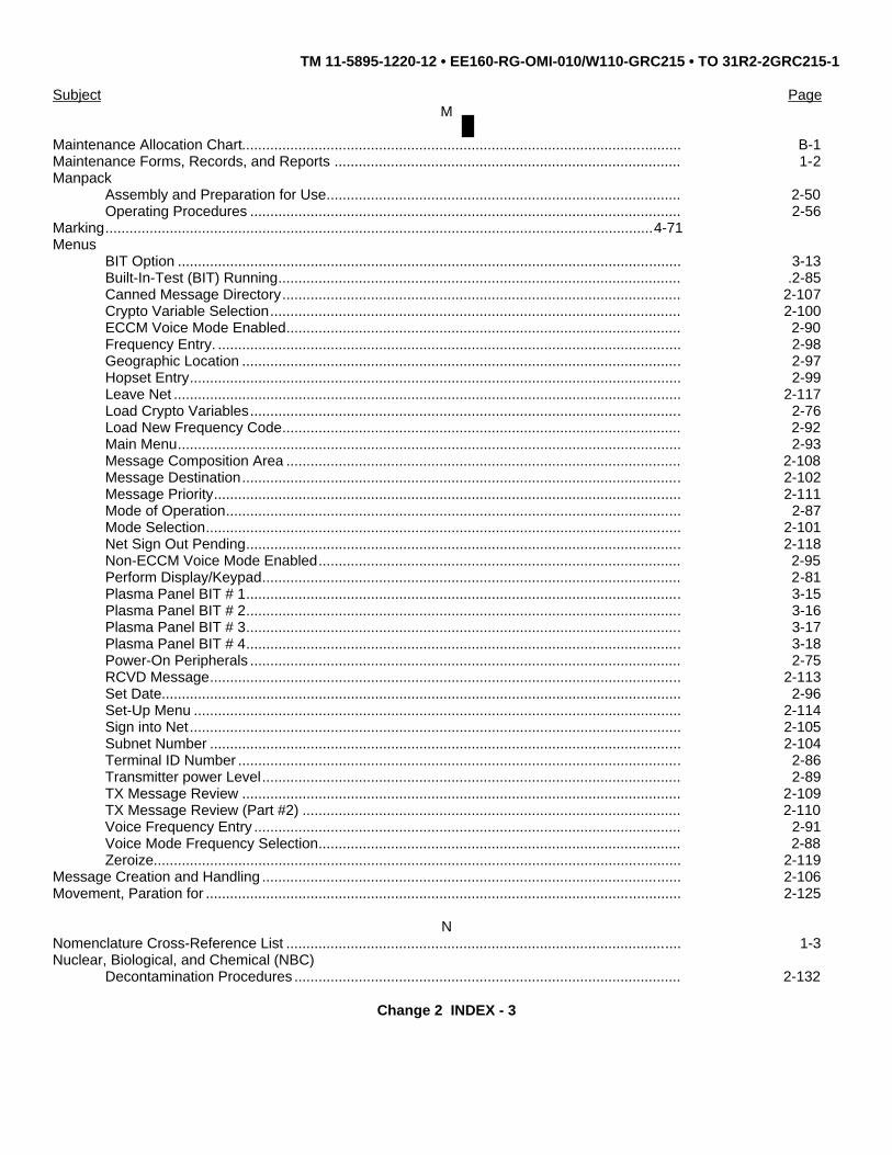
TM 11-5895-1220-12 • EE160-RG-OMI-010/W110-GRC215 • TO 31R2-2GRC215-1
Subject PageM
Maintenance Allocation Chart............................................................................................................. B-1Maintenance Forms, Records, and Reports ...................................................................................... 1-2Manpack
Assembly and Preparation for Use........................................................................................ 2-50Operating Procedures ........................................................................................................... 2-56
Marking........................................................................................................................................4-71Menus
BIT Option ............................................................................................................................. 3-13Built-In-Test (BIT) Running.................................................................................................... .2-85Canned Message Directory................................................................................................... 2-107Crypto Variable Selection...................................................................................................... 2-100ECCM Voice Mode Enabled.................................................................................................. 2-90Frequency Entry. ................................................................................................................... 2-98Geographic Location ............................................................................................................. 2-97Hopset Entry.......................................................................................................................... 2-99Leave Net .............................................................................................................................. 2-117Load Crypto Variables........................................................................................................... 2-76Load New Frequency Code................................................................................................... 2-92Main Menu............................................................................................................................. 2-93Message Composition Area .................................................................................................. 2-108Message Destination............................................................................................................. 2-102Message Priority.................................................................................................................... 2-111Mode of Operation................................................................................................................. 2-87Mode Selection...................................................................................................................... 2-101Net Sign Out Pending............................................................................................................ 2-118Non-ECCM Voice Mode Enabled.......................................................................................... 2-95Perform Display/Keypad........................................................................................................ 2-81Plasma Panel BIT # 1............................................................................................................ 3-15Plasma Panel BIT # 2............................................................................................................ 3-16Plasma Panel BIT # 3............................................................................................................ 3-17Plasma Panel BIT # 4............................................................................................................ 3-18Power-On Peripherals ........................................................................................................... 2-75RCVD Message..................................................................................................................... 2-113Set Date................................................................................................................................. 2-96Set-Up Menu ......................................................................................................................... 2-114Sign into Net.......................................................................................................................... 2-105Subnet Number ..................................................................................................................... 2-104Terminal ID Number .............................................................................................................. 2-86Transmitter power Level........................................................................................................ 2-89TX Message Review ............................................................................................................. 2-109TX Message Review (Part #2) .............................................................................................. 2-110Voice Frequency Entry .......................................................................................................... 2-91Voice Mode Frequency Selection.......................................................................................... 2-88Zeroize................................................................................................................................... 2-119
Message Creation and Handling ........................................................................................................ 2-106Movement, Paration for ...................................................................................................................... 2-125
NNomenclature Cross-Reference List .................................................................................................. 1-3Nuclear, Biological, and Chemical (NBC)
Decontamination Procedures ................................................................................................ 2-132
Change 2 INDEX - 3

TM 11-5895-1220-12 • EE160-RG-OMI-010/W110-GRC215 • TO 31R2-2GRC215-1
Subject Page
OOperation
Description and Use of Controls and Indicators .................................................................... 2-1Initial Adjustments, Daily Checks and Self Test .................................................................... 2-69In Unusual Weather .............................................................................................................. 2-131Manpack................................................................................................................................ 2-56Operational Check................................................................................................................. 4-33Principles of Operation .......................................................................................................... 1-29Team Terminal ...................................................................................................................... 2-69
Operational Check.............................................................................................................................. 4-33Operational Set-Up............................................................................................................................. 2-114Operator’s Quick Reference Guide .................................................................................................... vOperator’s Troubleshooting Table...................................................................................................... 3-2
PPA Removal and Replacement Description ....................................................................................... 4-40PMCS, Operator’s .............................................................................................................................. 2-30PMCS, Unit Maintenance ................................................................................................................... 4-8Power-Off Sequence .......................................................................................................................... 2-120Power-On Sequence .......................................................................................................................... 2-70Preliminary Servicing and Adjustment of Equipment ......................................................................... 4-2Preparation for Movement.................................................................................................................. 2-125Preparation for Storage or Shipment.................................................................................................. 1-3Preparation for Use ............................................................................................................................ 2-34Principles of Operation ....................................................................................................................... 1-29
RRecords, Reports and Maintenance Forms ....................................................................................... 1-2References ......................................................................................................................................... A-1Removal and Replacement of Major Components
Antenna Cable....................................................................................................................... 4-61ATU ....................................................................................................................................... 4-42ATU Safety Cap..................................................................................................................... 4-66Battery Case/Charger............................................................................................................ 4-36I/O Unit .................................................................................................................................. 4-57PA.......................................................................................................................................... 4-40RFO....................................................................................................................................... 4-55RN Modem ............................................................................................................................ 4-51RT.......................................................................................................................................... 4-34TSEC/KG-84A ....................................................................................................................... 4-46TSEC/KY-65A........................................................................................................................ 4-45TT PS .................................................................................................................................... 4-53Vehicular Adapter.................................................................................................................. 4-37Whip Antenna........................................................................................................................ 4-59
Repair Parts........................................................................................................................................ 4-1Repairs, Operator............................................................................................................................... 3-9Reporting Equipment Improvement Recommendations EIR’s........................................................... 1-2RFO Removal and Replacement ....................................................................................................... 4-55RN Modem Removal and Replacement............................................................................................. 4-51RT Removal and Replacement .......................................................................................................... 4-34
Change 2 INDEX - 4

TM 11-5895-1220-12 • EE160-RG-OMI-010/W110-GRC215 • TO 31R2-2GRC215-1
Subject Page
SSafety Cap, ATU
Description ............................................................................................................................ 1.16.1,2-19Installation and Replacement ................................................................................................ 4-66,4-69
Scope ............................................................................................................................................... 1-1Service Upon Receipt of Materiel....................................................................................................... 4-2Servicing and Adjustment of Equipment ............................................................................................ 4-2Show Message Procedures ............................................................................................................... 2-112Site Requirements.............................................................................................................................. 4-2Special Tools, TMDE, and Support Equipment.................................................................................. B-7storage, Administrative....................................................................................................................... 1-2Storage or Shipment, Preparation...................................................................................................... 1-3
TTeam Terminal Operating Procedures ............................................................................................... 2-69Testing
Manpack Off-Line BIT ........................................................................................................... 3-20Terminal Off-Line BIT ............................................................................................................ 3-12
TOD, Transfer Cable .......................................................................................................................... 3-20Tools and Equipment ......................................................................................................................... 4-1Troubleshooting Procedures, Operator .............................................................................................. 3-2Troubleshooting Procedures, Unit Maintenance ................................................................................ 4-7TSEC/KG-84A Removal and Replacement........................................................................................ 4-46TSEC/KY-65A Removal and Replacement ........................................................................................ 4-45TT PS Removal and Replacement..................................................................................................... 4-43
UUnit Maintenance Procedures ............................................................................................................ 4-33Unit PMCS.......................................................................................................................................... 4-8
VVehicular Adapter Removal and Replacement .................................................................................. 4-37Vehicular Configuration ...................................................................................................................... 1-24
WWarning Decals .................................................................................................................................. 2-127Weights and Dimensions ................................................................................................................... 1-20Whip Antenna Removal and Replacement ........................................................................................ 4-59
X-Y-ZZeroize Procedure.............................................................................................................................. 2-119
Change 2 INDEX-5/(INDEX-6 BLANK)

TM 11-5895-1220-12 • EE160-RG-OMI-010/W110-GRC215 • TO 31R2-2GRC215-1
By Order of the Secretary of the Army:
CARL E. VUONOGeneral, United States Army
Chief of Staff
Official:
WILLIAM J. MEEHAN IIBrigadier General, United States Army
The Adjutant General
By Order of the Secretary of the Navy:JOHN C. WEAVER
Rear Admiral, United States NavyCommander, Space and Naval Warfare
Systems Command
By Order of the Secretary of the Air Force:
LARRY D. WELSHGeneral, United States Air Force
Chief of Staff
Official:
CHARLES C. McDONALDGeneral, United States Air Force
Commander, Air ForceLogistics Command
Distribution:
To be distributed in accordance with special list.
�U.S. GOVERNMENT PRINTING OFFICE: 1990 - 712-094/20367


PIN:065850-000