Embed Size (px)
Citation preview

NCDA: Pickle SorterProject 98.09
Design Team Members:
Jon Hackett [email protected] (302)366-1505Nate Smith [email protected] (302)239-0345Alan Starr [email protected] (302)837-8664James Wert [email protected] (610)388-2679
Sponsor:Ed Kee [email protected] (302) 856-7303

Table of Contents
Executive SummaryIntroductionBenchmarkingConcept GenerationConcept Selection
Function #1: AlignmentFunction #2: IdentificationFunction #3: Removal
Working ModelIdentification Hardware and SoftwareComputer Algorithm for IdentificationActivation of Removal System
ExpendituresFABRICATION
Alignment SystemIdentification SystemEjection System
TESTINGAlignmentEjection
CONCLUSIONSAppendix
Drawing PackageAcknowledgements

Executive Summary
Of cucumbers grown domestically for the pickle industry, as much as 20%-25% isunusable due to shape defects. To eliminate these, pickles can be sorted either on theharvester, at the farm, or in the processing plant. The current method of manual sortingat the plant is an expensive process. Our mission is to provide an integrated, automatedsystem that removes the pickles with an undesirable shape from the processing line. Toaccomplish this, we have collected wants and constraints from the customers and used themetrics to create a design. We then built our system and tested iteratively to meet thetarget values for our metrics. Once a system has been developed for the processing line,it can possibly be adapted for use in the field.
After talking to customers, the most important wants for a system are cost,effectiveness, size, speed, and reliability. As a result, the top metrics used to evaluateconcepts are price, percentage of the undesirable pickles removed, percentage ofdesirable pickles removed, length and width. Following the benchmarking of systemsand functions to accomplish this type of task, functional concepts were developed. Usingthe metrics to evaluate the concepts for each function a complete system was developed.
This sorting mechanism begins with narrowing channels created by dividing wallsused to align the pickles. Once aligned, the pickles will pass under a camera where theywill be analyzed. If the pickles are deemed undesirable, the camera outputs an electricalsignal to the ejection system. Undesirable pickles are then removed from the stream ofdesirable pickles by a jet of air and pushed to another part of the conveyor belt.
The most critical function of sorting the pickles is to identify the misshapen ones.To accomplish this a machine vision system is used. Although possibly cost prohibitive,using an imaging system meets most of the wants well and is generally an industrystandard. However, the computerized part of analysis to accomplish this can be verycomplex. To remain within the budget, a black and white camera with an onboardprocessor was chosen. The imaging and analysis occurs within the camera. An externalcomputer is only required for software development.
Our final design surpassed our target values in terms of the alignment and ejectionfunctions. While the identification function has not been tested and proven, we feel thatit is capable of performing after more programming development. Our sponsor, Mr. Kee,is satisfied with the results and plans to use the system for further testing.
Introduction
The processing of pickles begins with the harvesting of cucumbers. In the UnitedStates, the pickle-harvesting season lasts approximately 80 days, July through September.However, not all of the harvested cucumbers are adequate for certain products, such assandwich pickles. When sorted, as much as 20-25% of the harvest is unsuitable forprocessing due to shape defects (Figure-1), and returned to the fields for disposal. Theseundesirable pickles fall into three categories: oversized, relish, and cul (Figure-2).Currently, the incoming cucumbers are sorted by hand to remove the undesirable ones.This manual grading (Figures-3 & 4) takes place following size separation (Figure-5) andrequires 3 to 4 people for each of the eleven tables. The costs associated with manualsorting at a typical plant are approximately $185,000 per (80 day) season for labor alone.
We refer to figures for only the US harvesting season since during the remainder of theyear, pre-sorted pickles are flown in from other areas. Our mission is to provide anintegrated, automated system that removes the undesirable cucumbers from theproduction line. To accomplish this, we have gathered customer wants and constraintsand developed metrics to measure them. After doing system and functionalbenchmarking, target values for those metrics were developed. Based on benchmarkingand brainstorming, a list of concepts was developed. A combination of the top conceptfrom each function (alignment, identification, and ejection) was selected. Afterfabricating, the system was tested and evaluated against the target values for the metrics.
Our customers for this project are those people involved directly in the harvestingand production of pickles, as well as the general consumer. A list of customers alongwith their wants is included in the appendix as Figure-6. Customers were ranked by theirinfluence on the pickle industry, amount of knowledge of pickle production, andimportance. The top three customers are Ed Kee, Vlasic, and Ray Kenning. These arethe most important customers because they represent a cross-section of the customer listand they will be the most affected by our solution. Our sponsor, Ed Kee from theUniversity of Delaware Agriculture Department, is ranked the highest because he hasknowledge of all levels of pickle production. Customers gave us a list of their wants.We then weighted these wants by the ranking of the customer and by the order ofimportance they were to the customer (Figure-6). After talking to several customers,some role-playing, and a visit to the Vlasic plant in Delaware, we have ranked the topfive wants using the SpreadSheet Design Process (SSD):
Wants:1) Cost2) Effectiveness3) Working area (size)4) Speed5) Reliability
Wants are considered tradable, unlike the constraints:
Constraints:1) As a standard, the solution must be safe to use2) Must meet Government agricultural regulations3) A $3000 budget provided by our sponsor, Mr. Kee
In order to allow for the evaluation of benchmarks and new concepts, wegenerated a list of metrics to measure the wants. By carrying out a wants-to-metricscross-correlation (Figure-7) we were able to identify the most important metrics for thesolution. The top three are throughput-speed, percentage of undesirable pickles removed,and setup costs.
Once our metrics were derived and ranked, we began the concept generationprocess. Through information gathered from benchmarking and brainstorming wegenerated a list of concepts for each of the three main functions of the system: alignment,identification, and removal. These concepts were then evaluated with the list of metrics
and a single best system concept was selected. The justification of this concept alongwith a working design follows.
Benchmarking
Benchmarking serves two roles: identifying possible concepts for use in oursolution, and determining best practices. Our benchmarking approach included collectingdata via the following:
• Patent searches• Internet searches• Trade magazines• Speaking directly with competitors
We began by looking at the broad area of material handling, which providedmethods of conveying, orienting and sorting items of any type on a production line. Nextwe looked at the methods of object identification for production line items. Finally, wedid specific searches on the identifying and sorting of produce.
System benchmarking yielded many complete identification/sorting systems forvarious production line applications. Of those, four were found which are madespecifically for food and produce applications: SRC Vision, Inc., Autoline, The ButtonCo., and Backus. These four, along with the other systems were analyzed to determinemethods of handling each function. A machine vision identification system was found tobe a common component of the benchmarks of complete systems. The machine visionsystem consists of one or multiple cameras to capture an image, a frame grabber and dataacquisition board, application specific software to analyze the image and an output signalto provide the desired system response. The imaging system can be coupled to any oneof a variety of ejection/sorting mechanisms, which are controlled by the output signal.The most commonly found ejection/sorting mechanisms were air jet, pneumatic piston,trapdoor, tilting tray, robot and moving gate.
While none of the system benchmarking results are currently in use or applicablefor the sorting of cucumbers by shape, there are several systems used to sort produce andother food items by size, color, weight and other parameters. SRC Vision, Inc. hasseveral systems in use in the produce industry that utilize optical scanners to identifycolors and air ejection for sorting. Autoline is a cucumber sorting system that usesimaging to measure length and controls a tilting tray sorter mechanism. The Button Co.has a harvester mounted optical scanner coupled with a robotic arm for the color sortingof tomatoes as they are picked. Backus, a firm that has been communicating with RayKenning, is considering developing a complete system for the pickle industry. Thissystem has an estimated price of $80,000 per line and they would need to hire aprogrammer.
It was clear from the system benchmarking that the key features of the systemsare processing speed and effectiveness. Almost all competitors cited their ability torapidly identify and remove ‘bad’ items from the line. Autoline claims a throughputspeed of 12 items per second. Several competitors also made reference to the precisionor effectiveness for their identifying and sorting systems.
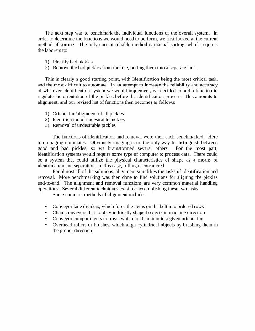
The next step was to benchmark the individual functions of the overall system. Inorder to determine the functions we would need to perform, we first looked at the currentmethod of sorting. The only current reliable method is manual sorting, which requiresthe laborers to:
1) Identify bad pickles2) Remove the bad pickles from the line, putting them into a separate lane.
This is clearly a good starting point, with Identification being the most critical task,and the most difficult to automate. In an attempt to increase the reliability and accuracyof whatever identification system we would implement, we decided to add a function toregulate the orientation of the pickles before the identification process. This amounts toalignment, and our revised list of functions then becomes as follows:
1) Orientation/alignment of all pickles2) Identification of undesirable pickles3) Removal of undesirable pickles
The functions of identification and removal were then each benchmarked. Heretoo, imaging dominates. Obviously imaging is no the only way to distinguish betweengood and bad pickles, so we brainstormed several others. For the most part,identification systems would require some type of computer to process data. There couldbe a system that could utilize the physical characteristics of shape as a means ofidentification and separation. In this case, rolling is considered.
For almost all of the solutions, alignment simplifies the tasks of identification andremoval. More benchmarking was then done to find solutions for aligning the picklesend-to-end. The alignment and removal functions are very common material handlingoperations. Several different techniques exist for accomplishing these two tasks.
Some common methods of alignment include:
• Conveyor lane dividers, which force the items on the belt into ordered rows• Chain conveyors that hold cylindrically shaped objects in machine direction• Conveyor compartments or trays, which hold an item in a given orientation• Overhead rollers or brushes, which align cylindrical objects by brushing them in
the proper direction.

Physical sorting or removal can also be accomplished by one of several existingmechanisms:
• Tilting tray sorters are popular in mail and package handling• Trap doors are used for many durable objects• Diverging chain conveyors separate objects by size• Diverting gates are used to redirect the flow of objects• Pneumatic pistons and air jets are effective means for quick, accurate removal of
individual items from a line.• Robots can be tooled to remove a wide variety of items from a conveyor belt.
The remaining function, identification, is the most critical function of the entiresystem. This designation is based on the fact that, while there are several techniques toeffectively align and remove the pickles, there are no existing systems that identifyundesirable pickles based on geometric characteristics. Our functional benchmarking ofidentification systems yielded various machine vision systems able to identify itemsbased on size, color and other surface characteristics. All of these are PC based systemsas described above under the system benchmarking.
Concept Generation
With our critical functions identified, and a list of quality benchmarks for all partsof the system, we began the concept generation process. While our benchmarking wasthe foundation for our concept list, we also brainstormed to come up with solutions toaccomplish these functions. Here we list most of these brainstormed concepts, with someof them combined into a slightly more general concept. Three concepts for thealignment, all of which are currently in use at various parts of the pickle processing line,are chain conveyors, lane dividers, and overhead rollers. The six sorting techniques listedabove (air jet, pneumatic piston, trap door, tilting tray, robotic arm, and diverting gate)were identified as being possible solutions for removing the undesirable pickles.
The list of concepts for identification includes an imaging system, along with fourbrainstormed ideas. The first of these other ideas, and by far the simplest, is a slantedconveyor belt, which would separate the pickles based on different rolling characteristics.It was expected that pickles with a greater curvature would take more time to roll. Nextis a system that takes a physical impression of the pickle to determine its shape (Figure-8). The system consists of a top belt, above the conveyor, made up of a field of smallpiezo-electrically-controlled measuring needles. As the pickles pass under this beltnumerous points on the surface are measured, resulting in a model of the pickle’s shape.This model is then compared to the acceptable shape, and the appropriate output isgenerated. The final two are different variations of a caliper system (Figure-8) tomeasure the pickle diameter at multiple points along its length. For the first the picklewould come to a stop, with one side against a wall, while three ‘fingers’ (calipers)retracted against the other wall. The amount of difference between the threemeasurements would determine the acceptance of the pickle. The variation of this is tokeep the pickle moving and to use rollers in place of the fingers. The offset between

rollers at a given instant when all rollers are deflected by a minimum amount wouldprovide the same result.
After identifying the important features and ranking our list of customerwants, we generated our list of system metrics (Figure-7). Customer wants, in order ofimportance, are cost, effectiveness, working area, speed, reliability, adaptability,portability and simplicity. We generated a list of metrics based on our customer wantsand key competitor features in order to evaluate the concepts and our final selection. Wealso came up with target values for these metrics based on customer input andcompetitive specifications. The top metrics and target values are tabulated below inTable-1.
Table-1 Metrics and Target Values
METRICS TARGET VALUES
Price ≤ $30,000 per sorting stationPickles per minute ≥ 530 per minute% Undesirable removed ≥ 80%% Good removed ≤ 5%Mean-time to failure ≥ 365 daysWeight ≤ 300 lbs.Length ≤ 20 ftWidth ≤ 4 ft
Combining the concept lists for each function results in a list of over one hundredpossible combinations of total system solutions. The next step was to evaluate theconcepts based on our list of metrics and come up with the best solution to the problem.
Concept Selection
Our concept selection process aimed to eliminate weak concepts and select thestrongest ones. The elimination process is partially based on the SpreadSheet Design
(SSD) method, and partially based on direct comparison, determined by how well aparticular concept satisfies each metric. The iterations required by the SSD methodeventually produce the best concepts, whereas the second method described requires noiteration.
We have two possible methods for comparing the possible solutions. The firstmethod, based on the iterative approach of the SpreadSheet Design (SSD) method, allowsranking of solutions by weighting the customers' wants. SSD was used as a guide for thisprocess because it is geared more towards differentiating between complete solutions andnot a function-by-function comparison. A second method, that of direct comparison, wasused under each metric. This helped clearly identify some of the poorer and strongersolutions. Each function can be considered independently when doing a comparison. Asmentioned, identification and ejection work faster with the pickles aligned. The majorityof the concepts we have for each function can be used with almost any combination ofthe other functional concepts, yielding a very large number of possible system concepts.For this reason the functional concepts are best evaluated individually. This is to avoid

comparing the several hundred combinations that would result from mixing-and-matching interchangeable function concepts as system benchmarks. The resulting “best”concept from each function group then becomes part of one system concept representingthe best of all of the functional concepts. The functional concepts are presented here inorder of their ranking, from best to worst (Figure-9). The different direct comparisonscan be found in the appendix as Figures-10 through 16.
There are a few basic physical principles that any acceptable concept must meet.Overall size is limited by the surrounding space of the grading stations. Because thegrading stations are on an elevated steel platform and will be mounted on the gradingstations, a weight limit is necessary. Finally, the system will be in use in an outsideenvironment (under roof only); therefore it must be able to withstand fluctuations intemperature and humidity.
Function #1: AlignmentHere we consider alignment first. The cost of modifying the existing system
eliminates all but two possibilities. Lane dividers and overhead rollers would not requiremodification of the belt itself and would reside above it. The next consideration is thatoverhead rollers work better when combined with chain conveyors and require morespace. In order to design a system that lends itself to accuracy and speed (which weknow to be high priorities), it was decided that the cucumbers should be aligned beforeattempting to identify and remove the undesirable ones.
Concept #1: Lane DividersWalls splitting the stream of flow form narrowing channels (Figure-4)
Concept #2: Overhead RollersRubber wheels freely spin (works well with chain conveyors) (Figure-5)
Concept #3: Chain ConveyorsThe chains (Figure-5) form grooves
Concept #4: Conveyor Compartments
Function #2: IdentificationOnce the pickles are aligned, the identification process becomes easier. It is clear
why imaging is an industry standard. It is small, fast, and easily configurable. Machinevision, however, is possibly cost prohibitive, especially with a small budget.Identification is the most critical element of the design – lack of a suitable identificationsolution is the reason that expensive manual labor has been utilized for so long, and is amuch more challenging problem to solve than alignment or ejection.
Concept #1: ImagingComputer controlled machine vision
Concept #2: Piezoelectric Pin based surface modelingThis technique measures the surface of the pickle in 3-D by passing the picklesunder a belt containing a field of piezoelectric pins (Figure-8) which contour tothe surface of the pickle. The offset of each pin is measured and translated to a 3-D model. This image is then compared to the acceptable image in the same waythat an optical imaging system works.

Concept #3: Width Measuring Calipers/Fingers (Figure-8)Working with a data acquisition PC, the three fingers measure curvature
Concept #4: Inclined ConveyorExpects straight (good) pickles to roll first, leaving overly curved ones to beredirected in some manner.
Function #3: RemovalRemoving undesirable pickles can be easily done by a variety of methods.
Requiring the least number of moving parts and of small size would be pneumatic jets.This solution is also relatively less expensive. No matter how good the alignment andidentification are, it is important the undesirable pickles actually get removed from theproduction line. The execution of this step is key, but not difficult to solve, since severalacceptable methods already exist in practice within the industry, and in others.
Concept #1: Pneumatic Jet/PistonThis method requires a blast of air to push undesirable pickles off of the line, orinto a ‘rejected’ bin.
Concept #2: Mechanical PistonThis is very similar to concept #1, the pneumatic piston, but has a few keydifferences.
Concept #3: Tilting TrayConcept #4: Trap DoorConcept #5: Robotic Arm
Having considered each function separately, the best of each was chosen for thecurrent situation. Each function is necessary to accomplish the task, but can beconsidered separately. Combining the three solutions gives the best complete systemsolution. The selection process leads to the following components for the final system:lane dividers to align the pickles, a computer controlled imaging system foridentification, and a pneumatic jet to remove the undesired pickles from the line. Thesehave been combined into a working model on a conveyor donated by Mr. Kee (Figures-17 through 20).
Working Model
The working model we have prepared consists of a model for each of the chosenfunctional benchmarks. These are:
• Aligning using narrowing channels created by lane dividing walls• Identification by a computer controlled imaging system• Removal by air jet, triggered by an output signal from the imaging system

Identification Hardware and SoftwareOur identification hardware consists of the following items:• Self-Contained Digital Camera• PC for Software Development• I/O Interface with Ejection System• External Relay
The camera performs all the functions that a camera/frame-grabber/PCcombination would perform in a more typical setup, with the exception of providing adevelopment environment. In other words, once a program is uploaded to the camera andstarted (which can also be automated), it does not require a PC to be present to run. Itperforms all the digital signal processing required and then puts a voltage on an outputpin that runs to the external relay in series with the pneumatic ejection valve. In additionto the information here, a manual for using the camera is included in the Appendix.
The relay is controlled by a data-logger so the duration of the pulse can becontrolled independently, without reprogramming the camera. This is because if weprogram the camera to simply send a pulse at the appropriate time when it identifies a badpickle, and use the data-logger to control the actual length of the pulse, we avoidreprogramming the camera while testing the removal system. This means that thecomputer need not be present while testing the removal system as well. However, if adata-logger is not available, the program can be modified to control the pulse duration aswell, although this may be considered an inefficient use of the camera’s resources, sinceit would slow the identification currently in progress. In this way, the data-logger is partof the prototype, but not of the finished system.
Our identification software consists of the following items:• VC/RT Real-time operating system (for the camera)• VCLib 2.0 Imaging Library• ADSP 2181 Development Environment(Special Version of the gcc ANSI C compiler cross-linked for the ADSP 2181)• Serial Communications program for communication between PC and Camera
• Hyperterminal• ProCOMM
• Custom Program – ‘picklesort v0.1’ (current code base found in Appendix)• Vision Components Graphical Shell v1.0 for camera operations• Windows95 PC Operating System (needed for Graphical Shell above)
Computer Algorithm for Identification1 Image captured in gray scale, tolerance level set based on histogram, image
flattened to black white, resulting in a 2-D array of pixels. The software is able tocharacterize shapes and disregards pickles that are not in the main focus.
2 For each collection of black pixels, computer identifies distance between furthesttwo black pixels as pickle length.

3 In the perpendicular direction to length, the distance between the pixel furthest tothe left and the pixel furthest to the right of the line connecting the endpoints isdesignated total width.
4 At the center of the pickle’s length, an actual width measurement is taken.5 The value of the total width minus the actual width is the offset distance or
amount of curvature.6 Crook Identification: If the offset distance is 30% or more of the pickle length, an
electrical signal is sent to the removal device to eject the pickle.7 Nub Identification: Width measurements are taken at a distance of 1/10 the total
length in from each end. If either end has a width of less than 80% of the actualwidth, an electrical signal is sent to the removal function to eject the pickle.
8 Also, if the center width is 75% or less of either end width, an electrical signal issent to the removal function to eject the pickle.
For more information about the algorithm, please consult the code base in the Appendix.During testing any of the above parameters may be adjusted for optimal performance.
Activation of Removal SystemThe camera stores the time at which a still image is taken, knows the distance to
the proper jet, knows the speed of the conveyor, and can therefore tell the jets a specifictime to release the pressurized air and eject the pickle. Air ejection is controlled by a 4-way solenoid valve, which is activated by a 12V signal from the imaging system.
The removal system will be positioned immediately following the imaging areaand consist of lines of air projecting horizontally in the transverse direction of the belt.
Budget
Time:
• Engineering Development Time♦ Alignment 32 hrs♦ Ejection 86 hrs♦ Imaging 140 hrs
• Fabrication Time♦ Alignment 20 hrs♦ Ejection 72 hrs♦ Imaging 54 hrs
A majority of development time was spent on the imaging system. This was dueto the time needed to obtain a camera within our budget and to create the program for it.Fabrication of the ejection system also took up a lot of time due to inexperience.
Expenditures:

A breakdown of the expenditures can be found in the appendix as Figure-21.Also included is a list of parts donated by Dr. James Glancey and Mr. Ed Kee as Figure-22. It can easily be seen that the camera and associated hardware used about 93% of ourgiven budget of $3000. A major cost that we did not have to incur was the conveyor.FABRICATION
Alignment SystemThe alignment system refers to the lane dividers, support bars, and all associated
hardware. The lane dividers are 1/8” thick pieces of HDPE cut to various lengths, allwith a height of 7-5/8”. The support bars are cut from 2” x 1/4" bar stock to lengths of21”. There are a total of 5 support bars. The support bars span the width of the conveyorat 8”, 40.5”, 46.25”, 64.5” and 88”, measured from the entry end of the conveyor. Thesupport bars are secured to the conveyor walls at each end with 2” ‘L’ brackets. The lanedividers are hung from the support bars with 2” L-brackets. There are a total of four lanedivider pieces. The first is 56.5” long and runs straight from the 1st to the 4th support bar,at a distance of 12” off the front wall (wall with ejection controls) of the conveyor. Thesecond and third pieces make up the converging alignment walls and are 41” in length.One of them attaches to the first support along the front wall, the other attaches to thefirst support at 12” from the front wall. Next they attach to the 2nd support at 4” and 7”respectively. Their ends also attach to the 3rd support at 4” and 7” respectively. Thefourth piece is 5-1/2” in length and is supported by the 5th support at a distance of 12”from the front wall.
Identification SystemThe identification system consists largely of camera, at least conceptually, but a
structure is needed to support it over the conveyor belt. From 3/4-inch outer diametersteel rods, two identical 24.25” long sections are cut for use as support posts, with 1/4”holes at 2 and 5 inches from the base. The blocks in our drawings (PS001) are thenmounted on these posts with two smaller, 1/2-inch posts running through the holesorthogonal to the support posts. Another block,(PS002), with the camera mount attached,is slid onto these two horizontal posts with clamps on either side, and then locked off atthe other end’s support post with similar post clamps. The camera can then be attachedto the L-bracket mount (PS003) on the center block, with a 1/4-inch long, 1/4-20-threadscrew.
Ejection SystemThe ejection system refers to all components that go into the functioning of the air
propulsion, beginning at the camera’s PLC output and ending at the air nozzle. Thecamera is connected directly to a Campbell Scientific 21X Micrologger (a data-logger),via a shielded pair cable from the camera’s PLC output to input H1 on the data-loggerand grounded to an appropriate terminal on the data-logger. The data-logger is alsowired to provide a manual signal with a pushbutton switch wired between output terminalCAO 1 and input terminal H1. This push-button switch and a four-pin connector plugfrom the camera lead are mounted in an enclosure on the side of the data-logger (PS004).The program for the data-logger can be found in the appendix as Figure-16.
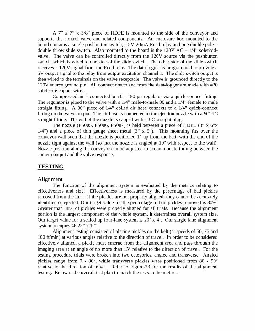
A 7” x 7” x 3/8” piece of HDPE is mounted to the side of the conveyor andsupports the control valve and related components. An enclosure box mounted to theboard contains a single pushbutton switch, a 5V-20mA Reed relay and one double pole –double throw slide switch. Also mounted to the board is the 120V AC – 1/4” solenoid-valve. The valve can be controlled directly from the 120V source via the pushbuttonswitch, which is wired to one side of the slide switch. The other side of the slide switchreceives a 120V signal from the Reed relay. The data-logger is programmed to provide a5V-output signal to the relay from output excitation channel 1. The slide switch output isthen wired to the terminals on the valve receptacle. The valve is grounded directly to the120V source ground pin. All connections to and from the data-logger are made with #20solid core copper wire.
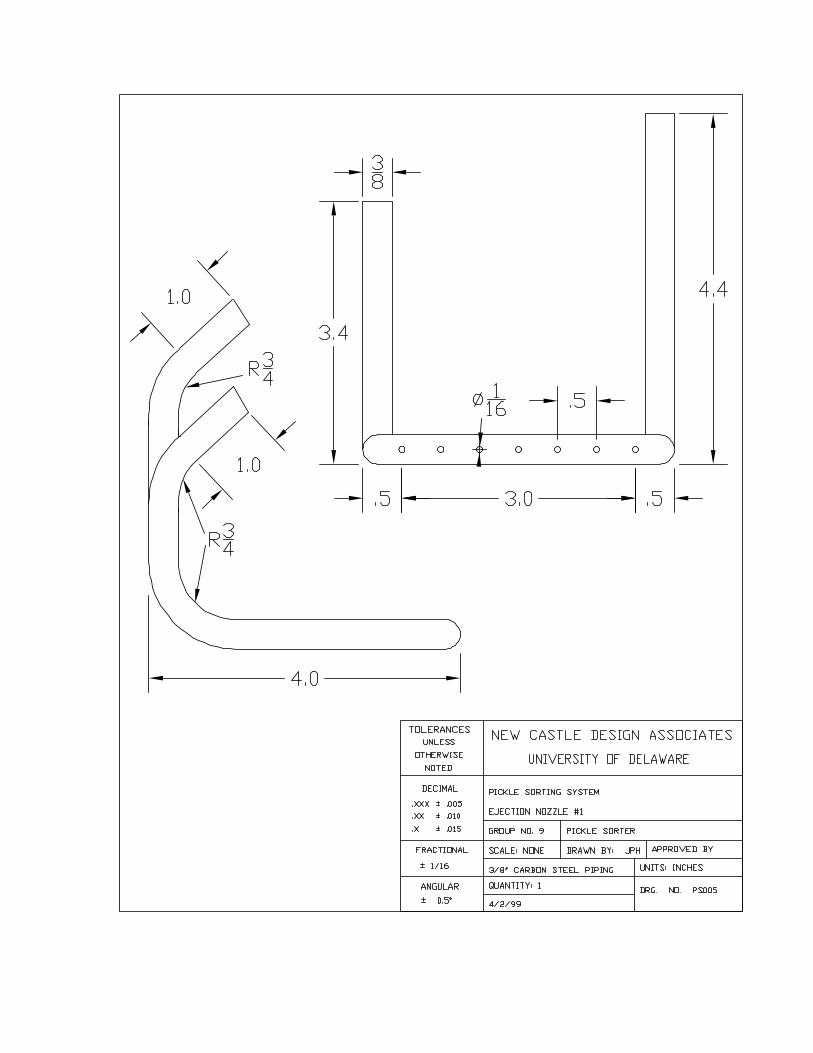
Compressed air is connected to a 0 – 150-psi regulator via a quick-connect fitting.The regulator is piped to the valve with a 1/4” male-to-male 90 and a 1/4” female to malestraight fitting. A 36” piece of 1/4” coiled air hose connects to a 1/4” quick-connectfitting on the valve output. The air hose is connected to the ejection nozzle with a ¼” JICstraight fitting. The end of the nozzle is capped with a JIC straight plug.
The nozzle (PS005, PS006, PS007) is held between a piece of HDPE (3” x 6”x1/4”) and a piece of thin gauge sheet metal (3” x 5”). This mounting fits over theconveyor wall such that the nozzle is positioned 1” up from the belt, with the end of thenozzle tight against the wall (so that the nozzle is angled at 10° with respect to the wall).Nozzle position along the conveyor can be adjusted to accommodate timing between thecamera output and the valve response.
TESTING
AlignmentThe function of the alignment system is evaluated by the metrics relating to
effectiveness and size. Effectiveness is measured by the percentage of bad picklesremoved from the line. If the pickles are not properly aligned, they cannot be accuratelyidentified or ejected. Our target value for the percentage of bad pickles removed is 80%.Greater than 88% of pickles were properly aligned for all trials. Because the alignmentportion is the largest component of the whole system, it determines overall system size.Our target value for a scaled up four-lane system is 20’ x 4’. Our single lane alignmentsystem occupies 46.25” x 12”.
Alignment testing consisted of placing pickles on the belt (at speeds of 50, 75 and100 ft/min) at various angles relative to the direction of travel. In order to be consideredeffectively aligned, a pickle must emerge from the alignment area and pass through theimaging area at an angle of no more than 15° relative to the direction of travel. For thetesting procedure trials were broken into two categories, angled and transverse. Angledpickles range from 0 - 80°, while transverse pickles were positioned from 80 - 90°relative to the direction of travel. Refer to Figure-23 for the results of the alignmenttesting. Below is the overall test plan to match the tests to the metrics.
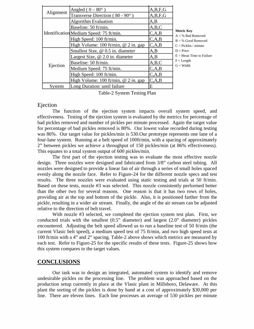
Table-2 System Testing Plan
EjectionThe function of the ejection system impacts overall system speed, and
effectiveness. Testing of the ejection system is evaluated by the metrics for percentage ofbad pickles removed and number of pickles per minute processed. Again the target valuefor percentage of bad pickles removed is 80%. Our lowest value recorded during testingwas 86%. Our target value for pickles/min is 530.Our prototype represents one lane of afour-lane system. Running at a belt speed of 100ft/min, with a spacing of approximately2” between pickles we achieve a throughput of 150 pickles/min (at 86% effectiveness).This equates to a total system output of 600 pickles/min.
The first part of the ejection testing was to evaluate the most effective nozzledesign. Three nozzles were designed and fabricated from 3/8” carbon steel tubing. Allnozzles were designed to provide a linear fan of air through a series of small holes spacedevenly along the nozzle face. Refer to Figure-24 for the different nozzle specs and testresults. The three nozzles were evaluated using static testing and trials at 50 ft/min.Based on these tests, nozzle #3 was selected. This nozzle consistently performed betterthan the other two for several reasons. One reason is that it has two rows of holes,providing air at the top and bottom of the pickle. Also, it is positioned farther from thepickle, resulting in a wider air stream. Finally, the angle of the air stream can be adjustedrelative to the direction of belt travel.
With nozzle #3 selected, we completed the ejection system test plan. First, weconducted trials with the smallest (0.5” diameter) and largest (2.0” diameter) picklesencountered. Adjusting the belt speed allowed us to run a baseline test of 50 ft/min (thecurrent Vlasic belt speed), a medium speed test of 75 ft/min, and two high speed tests at100 ft/min with a 4” and 2” spacing. Table-2 above shows which metrics are measured byeach test. Refer to Figure-25 for the specific results of these tests. Figure-25 shows howthis system compares to the target values.
CONCLUSIONS
Our task was to design an integrated, automated system to identify and removeundesirable pickles on the processing line. The problem was approached based on theproduction setup currently in place at the Vlasic plant in Millsboro, Delaware. At thisplant the sorting of the pickles is done by hand at a cost of approximately $30,000 perline. There are eleven lines. Each line processes an average of 530 pickles per minute
UNC ON S CAngled ( 0 – 80° ) A,B,F,GTransverse Direction ( 80 - 90° ) A,B,F,GAlgorithm Evaluation A,BBaseline: 50 ft/min. A,B,CMedium Speed: 75 ft/min. C,A,BHigh Speed: 100 ft/min. C,A,BHigh Volume: 100 ft/min, @ 2 in. gap C,A,BSmallest Size, @ 0.5 in. diameter A,BLargest Size, @ 2.0 in. diameter A,BBaseline: 50 ft/min. A,B,CMedium Speed: 75 ft/min. C,A,BHigh Speed: 100 ft/min. C,A,BHigh Volume: 100 ft/min, @ 2 in. gap C,A,B
System Long Duration: until failure E
Ejection
Identification
Alignment
Metric KeyA = % Bad Removed
B = % Good Removed
C = Pickles / minute
D = PriceE = Mean Time to FailureF = Length
G = Width

with a sorting effectiveness goal of 80% of all bad pickles removed, while removing nomore than 5% of the good ones. Undesirable, misshapen pickles account for 16 – 25% ofthe pickle harvest.
A total sorting solution would require three components; an alignment portion toguarantee all pickles passing through the system would be oriented in the same direction,an identification portion to determine which pickles should be removed and finally anejection portion to remove those pickles identified as unusable.
With this information we began benchmarking and brainstorming to develop a listof concepts that, together would provide an entire system solution. With a list ofconcepts for each of the three functions, we used our metrics and target values to evaluateand compare our concepts. The concept selection process resulted in one clear choice foreach of the three components; converging lane dividers for alignment, imaging for theidentification and air propulsion for the ejection.
Identification was determined to be the critical task based primarily on the factthat it is the one function that has never been successfully implemented in industry.Because our budget did not allow for the type of imaging system used in other industrialapplications, selection of a capable system that fit within our budget was a difficult task.While the design and fabrication of the other components was underway, we evaluatedthe options available to us for imaging. Typical imaging systems used in this type ofapplication consist of a digital camera, coupled to a frame grabber, controlled by a PCwith a data acquisition card. The minimum cost for this type if setup is $10,000-$12,000. A budget of $3,000 required an alternative solution.
A digital camera was located which contained it’s own processor as well as alibrary of functions. This eliminated the need for additional hardware and a PC wasassembled from spare parts to handle the programming. With this complete, a testableprototype was assembled within the budget constraints.
The tradeoff associated with the imaging system chosen is that a significantlygreater amount of programming time is required to set it up. This task paralleled theconducting of the test plan for the alignment and ejection mechanisms. Our test plan andresults demonstrate that for two of the three system functions, the most important targetvalues, related to price, effectiveness, throughput and size were met or surpassed.However, problems with programming prevented the imaging function from being testedwithin the time constraints allowed. And, therefore, the critical task has not been proven.
Despite the fact that all initial goals have not been met, the project is still a viablesolution to the problem. What we have to turn over to our customer is a testable systemwith successful alignment and ejection functions as well as an imaging system that, withfurther development, will be capable of meeting the initial goals. In order to aid in thefurther development and testing of the imaging system, a manual has been prepared aspart of the appendix, to accompany the prototype.

Appendix

Figure-1Categories of undesirable pickles.
Figure-2Examples of Crooks and Nubs (undesirable pickles that are too curved or too tapered)
Figure-3Photograph of the manual grading area at the Vlasic plant in southern Delaware. Notethat there are 11 sorting tables.
Oversized Relish Cul
3.80% 7.80% 6.80%
Misshapen - Crooks and Nubs
BrokenDiameter > 2 in.
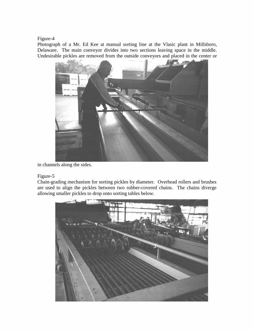
Figure-4Photograph of a Mr. Ed Kee at manual sorting line at the Vlasic plant in Millsboro,Delaware. The main conveyor divides into two sections leaving space in the middle.Undesirable pickles are removed from the outside conveyors and placed in the center or
in channels along the sides.
Figure-5Chain-grading mechanism for sorting pickles by diameter. Overhead rollers and brushesare used to align the pickles between two rubber-covered chains. The chains divergeallowing smaller pickles to drop onto sorting tables below.

Figure-6List of customers and their wants. The customers have been ranked in descending orderof importance.

Figure-7List of metrics used to measure customer wants
Figure-8Sketches of 2 of the brainstormed ideas for identification
3D Piezo-Electric Filed
3-finger Calipers
Effectiveness Speed Portability SimplicityQuality Metrics Cost Working Area Reliability AdaptabilityPrice a d d d d d d dPickles/minute d c d a d d a c% bad removed d a d d d d b c% good removed d a d d d d b cmean time to failure d d d d a d c cWidth d d a d d b b dLength d d a d d b b dWeight d d d d d a b c
a
b
cd
Denotes Very Strong Correlation
Denotes Strong Correlation
Denotes Weak Correlation
Denotes No Correlation

Figure-9Evaluation of Concepts Using a method based on the SpreadSheet Design method
Functional Concept Selection: Comparative Performance Scale of (0-5)Price % Good Rmvd Length
Pickles / Minute MTTF WeightList of Metrics → % Bad Rmvd Width
AlignmentConcepts Score
Lane Dividers 5 5 NA NA 5 5 4 4 28
Overhead rollers 3 3 NA NA 3 5 2 4 20Chain Conveyors 2 4 NA NA 2 5 3 2 18
Conveyor compartments 1 2 NA NA 1 4 5 3 16
Functional Concept Selection: Comparative Performance Scale of (0-5)Price % Good Rmvd Length
Pickles / Min MTTF WeightList of Metrics → % Bad Rmvd Width
IdentificationConcepts Score
Imaging System 1 5 5 5 5 5 5 4 35
Piezoelectric Pins 2 4 5 5 2 5 4 2 29Fingers / Calipers 3 1 3 4 3 5 4 3 26
Inclined Conveyor 5 2 1 1 4 4 1 2 20
Functional Concept Selection: Comparative Performance Scale of (0-5)Price % Good Rmvd Length
Pickles / Minute MTTF WeightList of Metrics → % Bad Rmvd Width
RemovalConcepts Score
Air Jet 5 5 5 5 5 5 5 5 40Pneumatic Pistons 4 4 5 5 4 4 5 5 36
Trap Door 3 3 4 3 3 4 4 4 28Tilting Tray 2 2 4 4 2 3 3 3 23Robotic Arm 0 4 4 5 1 2 5 2 23

Figure-10Direct comparison of costs
Figure-11Direct comparison of speed
Trap Door
Eje
ctio
n
Requires modification/replacement of existing conveyor, therefore more costly than other concepts.Robotic Arm Extremely expensive, costing more than $100,00 per robot when coupled with an identification
system.
Similar to pneumatic piston, but requires more maintenancePneumatic Jet/Piston Least expensive ejection concept. Parts may be built or purchased at little cost.Mechanical PistonTilting Tray Requires modification/replacement of existing conveyor, therefore more costly than other concepts.
Width Measuring Calipers/Fingers (see Figure-8)
Lower up front cost than imaging or pins. However, function requires stopping of the line, significantly increasing cost per pickle. This is still not a completely mechanical solution, and would require custom hardware and software
Iden
tific
atio
n
Inclined Conveyor Significantly less expensive than other concepts. Cost based on replacement of existing conveyor.
Imaging Very expensive, relative to other functions. However, the fact that no mechanical system exists to perform identification, the concept cannot be eliminated based on cost alone.
Piezoelectric Pin based surface modeling (see Figure-8)
Accuracy of the image, like cost, is directly proportional to the number of pins in the field. Also, because there is no existing prototype, this would need to be made as a custom job, and thus the price would be much higher than if it were already a production piece of equipment.
Alig
nmen
t
Lane Dividers Dividers are a one time cost, require no maintenance, and are inexpensiveOverhead RollersChain Conveyors
Conveyor Compartments
Rollers are a one time cost, require little maintenance, and are inexpensive.Using chain conveyors would require replacement of the existing conveyor, rather than adapting to it. Thus cost is significantly higher than dividers or rollers.Not cost-prohibitive, but not as inexpensive as dividers or rollers, since these would require some modification of the current line equipment.
Alig
nmen
t
Trap DoorRobotic Arm
Mechanical PistonTilting Tray
Iden
tific
atio
nE
ject
ion
One arm capable of removing 50-60 items per minute, which would meet the requirement.
Should not affect line speed however, dedicated compartments may reduce throughput.
Return time similar to tilting tray; requires time to close door.
Lane DividersOverhead RollersChain ConveyorsConveyor CompartmentsImaging
Inclined Conveyor
Pneumatic Jet/Piston
Removal speed would depend on pickle shape. The slower a pickle rolls, the greater distance along the conveyor it would travel, thus overall throughput could be negatively affected.Benchmarking provided mechanisms capable of 0.3 second cycle times, which easily surpasses our target value.Virtually identical in speed capabilities to a pneumatic piston.Relatively slower; it requires movement of the tray. Also would require more space between pickles
As we are unable to find an existing system of this type, we can not list benchmarks for this concept, and are not sure it could keep up with the conveyer rate used in the plant. Here this concept truly fails our most important metric, as this method would require the line to stop long enough for each pickle (or a set of them) to be analyzed by a set of pins/fingers.
Piezoelectric Pin based surface modeling (see Figure-8)Width Measuring Calipers/Fingers (see Figure-8)
These are already in use in other parts of the Vlasic plant and do not adversely affect the line speed.These are already in use in other parts of the Vlasic plant and do not adversely affect the line speed.These are already in use in other parts of the Vlasic plant and do not adversely affect the line speed.
Information from several of our imaging system benchmarks has shown that we can obtain an imaging system that will operate at the existing throughput speed.

Figure-12Direct Comparison of Percentage of Undesirable Pickles Removed
Figure-13Direct Comparison of Percentage of Good Pickles Removed
Trap Door
Robotic Arm Very effective provided speed capabilities are not exceeded.
Tilting Tray Capable of accurate ejection with reduced throughput compared to pneumatics. Motion of device requires more time.
Inclined Conveyor Simple tests showed little difference in the rolling characteristics of curved and straight pickles. Also, because some of the defective pickles are not curved (nubs), they would roll with the same properties as a good pickle
Pneumatic Jet/Piston We expect this method to remove upwards of 99% of the pickles that the Identification system tells it to.
Mechanical Piston
Iden
tific
atio
nE
ject
ion
Width Measuring Less accurate than imaging or surface modeling.
Capable of accurate ejection with reduced throughput compared to pneumatics. Motion of device requires more time.
Imaging Imaging and Edge-Detection algorithms have reached a fairly advanced level, and a good imaging software package with sufficiently fast hardware should be capable of accurately classifying a cucumber as good or bad in the time it will be given to do so.
Piezoelectric Pin based surface modeling
If the pin grid could be made finely enough, the identification of good and bad pickles should be nearly as good as the imaging solution.
Same as a pneumatic piston.
Alig
nmen
t
Lane Dividers Assuming alignment system functions as expected, there would be no negative impact on removal.
Overhead Rollers Assuming alignment system functions as expected, there would be no negative impact on removal.
Design presents problems/limitations in identification and ejection, thus negatively affecting the % undesirable removed.
Chain Conveyors Design presents problems/limitations in identification and ejection, thus negatively affecting the % undesirable removed.
Conveyor Compartments
Alig
nmen
t
Lane Dividers Not a factor in removal removal of good picklesOverhead RollersChain ConveyorsConveyor Compartments Not a factor in removal removal of good pickles
Not a factor in removal removal of good picklesNot a factor in removal removal of good pickles
Eje
ctio
n
Imaging
Piezoelectric Pin based surface modeling (see Figure-8)
If the pin grid could be made finely enough, the identification of good and bad pickles should be nearly as good as the imaging solution.
Width Measuring Less accurate than imaging or surface modeling.
Iden
tific
atio
n
Extremely fast cycle times result in accurate removal of only the pickles identified as bad.
Imaging and Edge-Detection algorithms have reached a fairly advanced level, and a good imaging software package with sufficiently fast hardware should be capable of accurately classifying a cucumber as good or bad in the time it will be given to do so.
Pneumatic Jet/PistonMechanical PistonTilting Tray Capable of accurate ejection with reduced throughput compared to pneumatics. Motion of device
requires more time.Capable of accurate ejection with reduced throughput compared to pneumatics. Motion of device requires more time.
Trap Door
Extremely fast cycle times result in accurate removal of only the pickles identified as bad.
Robotic Arm Very effective provided speed capabilities are not exceeded
Inclined Conveyor Simple tests showed little difference in the rolling characteristics of curved and straight pickles. Also, because some of the defective pickles are not curved (nubs), they would roll with the same properties as a good pickle
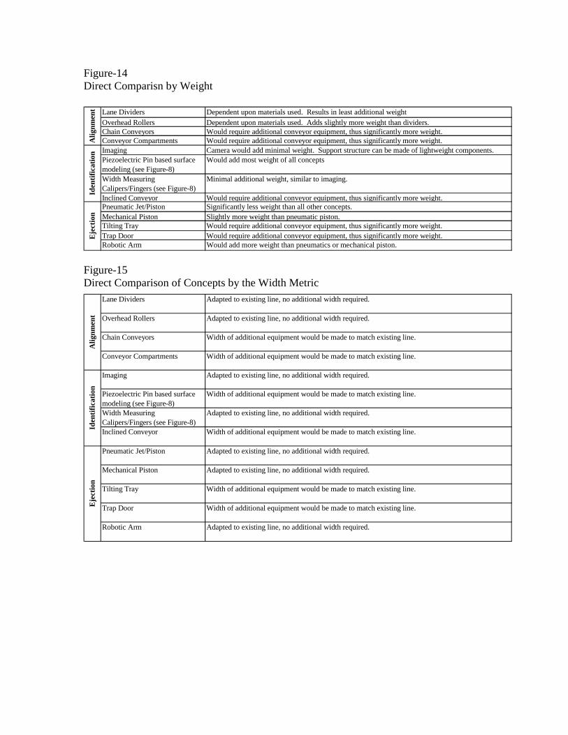
Figure-14Direct Comparisn by Weight
Figure-15Direct Comparison of Concepts by the Width Metric
Alig
nmen
t Lane Dividers Dependent upon materials used. Results in least additional weightOverhead RollersChain ConveyorsConveyor Compartments
Dependent upon materials used. Adds slightly more weight than dividers.Would require additional conveyor equipment, thus significantly more weight.Would require additional conveyor equipment, thus significantly more weight.
Would require additional conveyor equipment, thus significantly more weight.
Imaging Camera would add minimal weight. Support structure can be made of lightweight components.Piezoelectric Pin based surface modeling (see Figure-8)
Would add most weight of all concepts
Width Measuring Calipers/Fingers (see Figure-8)
Minimal additional weight, similar to imaging.
Slightly more weight than pneumatic piston.
Would require additional conveyor equipment, thus significantly more weight.Significantly less weight than all other concepts.
Eje
ctio
nId
entif
icat
ion
Robotic Arm Would add more weight than pneumatics or mechanical piston.
Inclined ConveyorPneumatic Jet/PistonMechanical PistonTilting Tray Would require additional conveyor equipment, thus significantly more weight.Trap Door
Eje
ctio
nId
entif
icat
ion
Robotic Arm Adapted to existing line, no additional width required.
Inclined Conveyor
Pneumatic Jet/Piston
Mechanical Piston
Tilting Tray Width of additional equipment would be made to match existing line.
Trap Door Width of additional equipment would be made to match existing line.
Imaging Adapted to existing line, no additional width required.
Piezoelectric Pin based surface modeling (see Figure-8)
Width of additional equipment would be made to match existing line.
Width Measuring Calipers/Fingers (see Figure-8)
Adapted to existing line, no additional width required.
Adapted to existing line, no additional width required.
Width of additional equipment would be made to match existing line.
Adapted to existing line, no additional width required.
Alig
nmen
t
Lane Dividers Adapted to existing line, no additional width required.
Overhead Rollers
Chain Conveyors
Conveyor Compartments
Adapted to existing line, no additional width required.
Width of additional equipment would be made to match existing line.
Width of additional equipment would be made to match existing line.

Figure-16A direct comparison of concepts by the length metric
Robotic Arm Adapted to existing line, requiring no additional length
Adapted to existing line, requiring no additional length
Inclined Conveyor
Pneumatic Jet/Piston
Mechanical Piston
Tilting Tray Would require additional conveyor equipment, thus significantly more length.
Would require additional conveyor equipment, thus significantly more length.Trap DoorEje
ctio
n
Imaging Adapted to existing line, requiring no additional length
Piezoelectric Pin based surface modeling (see Figure-8)
Device could require additional conveyor length depending on, design/performance. Difficult to predict as there are no existing systems.
Width Measuring Calipers/Fingers (see Figure-8)
Adapted to existing line, requiring no additional length
Iden
tific
atio
n
Adapted to existing line, requiring no additional length
Would require additional conveyor equipment, thus significantly more length.
Alig
nmen
t
Lane Dividers Adapted to existing line, requiring no additional length
Overhead Rollers
Chain Conveyors
Conveyor Compartments
Adapted to existing line, requiring no additional length
Would require additional conveyor equipment, thus significantly more length.
Would require additional conveyor equipment, thus significantly more length.

Figu
re-17C
om
plete S
ystem
Mo
de
l
Data-Logger toTime Ejection
Self Contained Camera
Lane Dividers toAlign Pickles
Pressure Regulator
Ejection Gap


Figure-18End view of the system. At the bottom are the converging lane dividers. The gap in thecentral wall allows the pickles to either drop from the side or to be carried along thecenter of the conveyor. The camera connects to the data-logger. In turn, it sends a signalto the solenoid, which allows the air to flow.
Lane Dividers toAlign the Pickles
Data-Logger to ControlEjection Timing
Camera Mounting
Air Ejection Nozzle

Figure-19Side view of complete system. On the left is the data-logger, used to control the durationof the air pulse. At the top-center is the camera. On the right are the air-hose hook-up,pressure regulator, and solenoid. The coil of hose goes over the wall to the nozzle.
Figure-20Here is the other side of the same wall. On the left is the ejection nozzle. A verticalramp leads up to it to prevent pickles from getting stuck.
Data-Logger
Camera on Mounting with2 Degrees of Freedom
Pressure Regulator
Nozzle
Lane Dividers
Solenoid
Camera on Mounting
Nozzle
Data-Logger
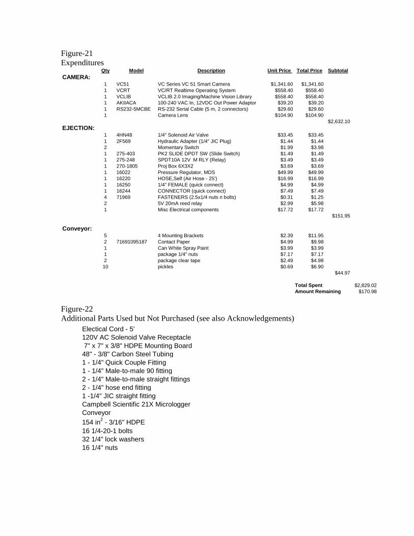
Figure-21Expenditures
Figure-22Additional Parts Used but Not Purchased (see also Acknowledgements)
Qty Model Description Unit Price Total Price SubtotalCAMERA:
1 VC51 VC Series VC 51 Smart Camera $1,341.60 $1,341.601 VCRT VC/RT Realtime Operating System $558.40 $558.401 VCLIB VCLIB 2.0 Imaging/Machine Vision Library $558.40 $558.401 AKIIACA 100-240 VAC In, 12VDC Out Power Adaptor $39.20 $39.201 RS232-5MCBE RS-232 Serial Cable (5 m, 2 connectors) $29.60 $29.601 Camera Lens $104.90 $104.90
$2,632.10EJECTION:
1 4HN48 1/4" Solenoid Air Valve $33.45 $33.451 2F569 Hydraulic Adapter (1/4" JIC Plug) $1.44 $1.442 Momentary Switch $1.99 $3.981 275-403 PK2 SLIDE DPDT SW (Slide Switch) $1.49 $1.491 275-248 SPDT10A 12V M RLY (Relay) $3.49 $3.491 270-1805 Proj Box 6X3X2 $3.69 $3.691 16022 Pressure Regulator, MDS $49.99 $49.991 16220 HOSE,Self (Air Hose - 25') $16.99 $16.991 16250 1/4" FEMALE (quick connect) $4.99 $4.991 16244 CONNECTOR (quick connect) $7.49 $7.494 71969 FASTENERS (2.5x1/4 nuts n bolts) $0.31 $1.252 5V 20mA reed relay $2.99 $5.981 Misc Electrical components $17.72 $17.72
$151.95
Conveyor:5 4 Mounting Brackets $2.39 $11.952 71691095187 Contact Paper $4.99 $9.981 Can White Spray Paint $3.99 $3.991 package 1/4" nuts $7.17 $7.172 package clear tape $2.49 $4.9810 pickles $0.69 $6.90
$44.97
Total Spent $2,829.02Amount Remaining $170.98
Electical Cord - 5' 120V AC Solenoid Valve Receptacle 7" x 7" x 3/8" HDPE Mounting Board 48" - 3/8" Carbon Steel Tubing1 - 1/4" Quick Couple Fitting1 - 1/4" Male-to-male 90 fitting2 - 1/4" Male-to-male straight fittings2 - 1/4" hose end fitting1 -1/4" JIC straight fittingCampbell Scientific 21X MicrologgerConveyor154 in2 - 3/16" HDPE16 1/4-20-1 bolts32 1/4" lock washers16 1/4" nuts

Figure-23Alignment Testing Results
Figure-24Nozzle Specifications and Testing
Trial # Straight Trial # Straight1 10 1 102 10 2 83 10 3 74 10 4 105 10 5 9
Result % 100 Result % 88
AlignmentAngled Transverse
Pulse Duration 1.0 s 0.5 s 0.3 s Angle 0° 10° Angle 0° 10°Nozzle #1 100% 75% 75% Nozzle #1 75% N/A Nozzle #1 50% N/ANozzle #2 100% 100% 75% Nozzle #2 75% 75% Nozzle #2 50% 75%Nozzle #3 100% 100% 100% Nozzle #3 75% 100% Nozzle #3 75% 100%
Static Testing @ 120psi 50 ft/min @ 120psi; 1.0 sec pulse 50 ft/min @ 120psi; 0.5 sec pulse

Figure-25Ejection Testing Results
Figure-26Overall System Results
Metrics Targets Alignment Identification Ejection SystemPrice per sorting station$30,000 $200 $10,600 $600 $11,400Pickles Per Minute 530 600 600 600% Bad Removed 80% 88% 86% 86%% Good Removed 5% N/A 1% 1%Mean Time to Failure 365 daysWeight 300 lbs. 110 lbs. 30 lbs. 40 lbs. 180 lbs.Length 20 ft 46 1/4 in. 12 in. 25 3/4 in. 7 ftWidth 4 ft 4 ft 1 ft 4 ft 4 ft
Trial # Ejected Trial # Ejected Trial # Ejected1 10 1 8 1 72 9 2 10 2 93 10 3 9 3 84 9 4 9 4 10
Result % 95 Result % 90 5 9Result % 86
Trial # Ejected Trial # Ejected Trial # Ejected1 10 1 8 1 82 10 2 10 2 93 10 3 10 3 104 9 4 9 4 85 10 5 10 5 9
Result % 98 Result % 94 Result % 88
Largest Size
Baseline Medium Speed High Speed
High VolumeSmallest Size

Figure-27Program for Data-Logger (100ft/min)
Initialize * 1 A Program 4 4 : P 8 91 : D 1 1 : 0 0 0 1
2 : 3Program 1 1 : P 30 3 : 4 0 0 0
1 : 5 0 0 0 mV 4 : 302 : 0 0 0 5
Program 5 5 : P 2 2Program 2 2 : P 2 1 1 : 0 1
1 : C A O 1 2 : 4 02 : 0 0 0 5 3 : 5
4 : 5 0 0 0Program 3 3 : P 0 1
1 : 0 1 Program 6 6 : P 9 52 : 1 53 : 0 14 : 0 0 0 15 : 1 . 0 06 : 0
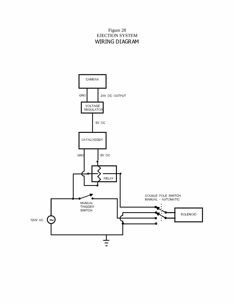
Figure 28EJECTION SYSTEM
:,5,1*�',$*5$0

Drawing Package


Camera Manual
Overview of camera and software developmentand Camera Documentation
Contents
I. Camera Overview
II. Hardware DocumentationA. VC51 Documentation/Specs (Prepared by Vision Components, Inc.)B. PC Specs
III. Software DocumentationA. Compiler Notes/Batch filesB. Image Library v2.0 DocumentationC. Utilities for working with the VC51D. Code base for Pickle Sorting (Monolithic)
IV. Important Contacts

I. Camera Overview
A camera is the heart of every Machine Vision system, and this one is noexception. However, this system differs radically from typical hardware in many ways.The more common systems use a setup as follows:
• Analog camera• A Frame grabber• A PC for data analysis
Our benchmarking revealed early on that the typical cost of these systems is$10,000 to $25,000. Since the budget for our project was $3,000, we were unsure of ourability to produce even a scaled-down version of a machine vision system that would beadequate for testing and development.
We were able to locate, however, a digital camera within our budget that is madefor industrial applications, and has it’s own processor, memory, and power board, all onthe camera. With such a camera, there is no need for a frame grabber, or for a PC to sitwith it while it is running. A PC is needed for the development of software to run on thecamera, of course, but a person who needs to use 40 cameras, wouldn’t need 40 PC’s inaddition.
The trade off in using such a camera for a project like ours is that it requires muchmore programming up front in order to establish a method of working with the camera,etc. The camera is actually quite a capable piece of equipment, especially when usedwith the image library we purchased along with it. We were actually quite lucky to find acamera within our budget, but the extra programming needed has prevented us frommeeting our original testing deadlines. Because of this, our primary goal has changedsomewhat. Now we aim to provide our customer with a system that lends itself to furthertesting and development, with as much basic functionality as possible.
Much time was invested in our search for a capable camera that fit in our budget. Whenwe finally found one in February, as much information as possible about the camera andit’s capabilities was gathered. We then purchased the camera and began work with it.The documentation for all the components of the camera is provided here, as well as forthe software we have used with it.
II. Hardware Documentation
Machine Vision Cameras VC11, VC13, VC21,VC51, VC61, VC61/C, VC65, VC65/C, VC67
This documentation was created very conscientiously. No liability is assumed for possible errorsor misleading descriptions. The information contained in this documentation is informative and inno way guarantees the characteristics of the product. The right is reserved to make technicalchanges dictated by the state of the art.
1. General information
The VC Series cameras are compact, light-weight black-and-white or color video cameras withvideo memory and an image processor.
They integrate a high-resolution CCD sensor with a fast image-processing signal processor. Adynamic RAM is used to store data and video images. Interfaces allow communication with theoutside world. The cameras set standards for performance and integration density.
These cameras are built for industrial applications. High goals were set as regards the imageresolution, the sturdiness of the casing, and the electromagnetic compatibility, as mere examples.The cameras are insensitive to vibrations and shocks, while permitting precise measurementsand tests. They are ideally suited as OEM cameras for mechanical engineering applications.
Only a supply voltage is required to operate the cameras (usually 12 volts). An image processingsystem or a PC with a frame grabber board is not necessary. Simple control problems can evenbe implemented with the integrated process interfaces. For more complex control tasks, thecameras can be connected with, for example, a PLC.
This documentation describes the cameras’ hardware . However, in many cases the softwaredocumentation is decisive. For this, please consult the software manuals.
2. Basic structure
The image is formed by a high-resolution CCD sensor. With the appropriate control chips, it itselfis in many ways comparable with a conventional video camera. However, instead of a “real” videosignal, a staircase-shaped signal is sent which is very advantageous for the later digitalization.The staircase-shaped signal is digitized. This 8-bit video signal can be used for various purposes.Via a bidirectional buffer, it is sent to the DMA interface of the ADSP2181 signal processor, whichin turn controls the functions “Record”, “Stills”, etc. Additionally, the digital video signal is sent tothe video output, where it is converted to an analog signal and can be connected to a videomonitor.
The electronic circuitry of the cameras is placed on four boards.
The following presents an overview of the boards:
Description Designation Function
Sensor board SEN059, SEN059/C Receives signals from and controls the CCDsensor, SEN055, SEN075 produces the video and clock signals,
black-and-white and color versions
CPU board CPU, CPU2 Digitalization of the video signal,complete signal processor with memory
Extension board EXT1, EXT2 Creates a video output signal in black-and-white or color - BAS or SVGA quality,
interfaces (V24, etc.)
Power board POW, POW5W Power supply 3W, 5W, PLC interfaces
The boards can be combined with one another in many different ways, allowing numerousoptions.
List of the currently possible board combinations:
Type Description Video sensor Processor Interfaces Supplyvoltage
VC11 standard version B/W SEN059 CPU EXT1 POW 3WVC13 low budget B/W SEN055 CPU EXT1 POW 3WVC21 SVGA output SEN059 CPU EXT2 POW 5WVC51 high performance B/W SEN059 CPU2 EXT1 POW 5WVC61 SVGA output SEN059 CPU2 EXT2 POW 5WVC61/C color, SVGA SEN059/C CPU2 EXT2 POW 5WVC65 prog. scan, SVGA SEN075 CPU2 EXT2 POW 5WVC65/C prog. scan, color, SVGA SEN075/C CPU2 EXT2 POW 5WVC67 megapixel prog. scan, SVGA SEN085 CPU2 EXT2 POW 5W
3. Documentation of the different boards
3.1 "SEN059", "SEN059/C" Board
This board takes the picture. The CCD sensor ICX059AL (black-and-white) or ICX059AK (color)is used. This board controls the CCD sensor and processes the analog signal. It outputs a pixelclock signal and the video signal.
The signal processor can configure the controller chip for the CCD sensor. This involves thefollowing modes:
field integration frame integrationinternal sync external sync
vertical reset (external sync mode only)
shutter: high speed (up to 1/10000)low speed (up to 510 half-size images)flickerless
For the exact setting of the configuration, refer to the description of the configuration program inthe software documentation .
3.2 "SEN055" Board
This board is used as a substitute for the "SEN059" board for low budget applications. The CCDsensor used (ICX055AL) has a lower resolution of 500x582 pixels, which is, however, adequatefor many applications.
The signal processor can configure the controller chip for the CCD sensor. This involves thefollowing modes:
field integration frame integration
shutter: high speed (up to 1/80,000)
For the exact setting of the configuration, refer to the description of the configuration program inthe software documentation .
3.3 "SEN075" Board
This board is used as a substitute for the "SEN059" board. The progressive scan type CCDsensor used (ICX075AL) is ideally suited for industrial machine vision tasks. In contrast to theconventional technique it provides the following features:
- 1/2“ sensor (else: 1/3“)- higher resolution: 782x582 pixels- square pixel format- full-frame shutter- can be triggered externally- sensor read out in full-frame mode (non-interlaced)- shutter speed down to 5 µsec

The boards includes a programmable device (FPGA). The above functions could be provided withthis custom-programmed chip only.
The diverse features of this boards (high-speed and low-speed shutter, external trigger, etc.) areconfigured mainly via software.
For the exact setting of the configuration, refer to the description of the configuration program inthe software documentation .
3.4 "SEN085" Board
This board is used as a substitute for the "SEN059" board, for cases in which especially highresolution is required. The progressive scan type CCD sensor used (ICX075AL) is ideally suitedfor industrial machine vision tasks. In contrast to the conventional technique it provides thefollowing features:
- 2/3“ sensor (else: 1/3“)- very high resolution: 1280x1024 pixels- square pixel format- full-frame shutter- can be triggered externally- sensor read out in full-frame mode (non-interlaced)- shutter speed down to 5 µsec
The boards includes a programmable device (FPGA). The above functions could be provided withthis custom-programmed chip only.
The diverse features of this boards (high-speed and low-speed shutter, external trigger, etc.) areconfigured mainly via software.
For the exact setting of the configuration, refer to the description of the configuration program inthe software documentation .
3.5. "CPU", "CPU2" Board
The board contains an ADSP 2181 signal processor with 80 KBytes of internal RAM, plusdynamic RAM (DRAM), as well as nonvolatile flash EPROM memory.The board performs the A/D conversion of the video signal. The signal processor’s DMA functionallows the video signal to be stored in dynamic RAM. The stored or the live video signal is sent asa digital signal to the board “EXT1“ or “EXT2“, which process the signal for output to a monitor.An image overlay supplied directly by the signal processor is also forwarded to the “EXT” boards.This overlay makes it possible to display additional (binary) graphics, text, crosshairs, etc., on themonitor."CPU" and "CPU2" have different features, which are shown as follows:
Board CPU CPU2
processor ADSP2181 32MHz ADSP2181 40MHzDRAM 2 MBytes 8 MBytesFlash-EPROM 512 KBytes 2 MByteswait states (DRAM) 1 (20 MB/sec) 0 (40 MB/sec)performance 100 % 130 up to 200 %clamping analog digital (zero offset digitalclamping)

3.6 "EXT1" Board
The extension board "EXT1" is practically the periphery for the CPU board. Here, the digital videosignal is converted to an analog signal. The overlay bit and the synchronization signal areheterodyned. The resulting analog output video signal is fed to a BNC socket on the rear panel ofthe camera.
This board also converts the voltage level for the serial V24 interface.
A third function is that the board supplies four TTL/CMOS-compatible inputs and outputs.However, these signals are galvanically separated, and their levels are adjusted, on the separate“POW” board.
3.7 "EXT2" Board
This board’s periphery functions “V24 voltage level conversion” and “TTL/CMOS inputs andoutputs” are identical to those of the “EXT1” board.However, this board has a SVGA-quality video output signal, requiring considerably morecomplex processing of the video signal.The input of the video refresh memory (with a maximum size of 960x612x8 bits) is fed with thedigital video signal at 14.375 MHz, usually with line interlacing. There are three modes for the twoleast-significant bits of the video data (BIDAT[1..0]):
1. Normal: the data is written to the video refresh memory without modifications2. Overlay: BIDAT[0] is replaced by the overlay bit3. Color/frame for the reproduction of True Color information, a 2-bit color code is written to thevideo
memory refresh. This code makes sure that a 6-bit lookup table with the rightcolor is
selected for the video output. The right color is that color which corresponds tothe
color of the pixel on the CCD sensor.4. Color/field like no. 3, but the pixels are assigned for field integration mode
The technical specifications for the SVGA output signal are as follows:
Horizontal frequency: 35.23 kHz VBP: 12 linesVertical frequency: 58.52 Hz VFP: 12 linesResolution SVGA: 600x800 (reduced) HSYNC width: 64 pixelsResolution eff. hor.: 752 HBP: 46 pixelsResolution eff. ver.: 574 HFP: 46 pixelsVSYNC width: 4 lines Pixel frequency : 31.921875 MHz
The video is converted from an interlaced signal to a noninterlaced signal by controlling the theread and write signals of the memory respectively.
The image is output with a three-fold 6-bit DAC using a color lookup table.

3.8 "POW" Board
This board contains the power supply for the entire camera. It is also responsible for the galvanicseparation of the signals, and tailors the levels of the PLC-signals (4 inputs, 4 outputs).
The camera is supplied with a nominal voltage of 12 V (+/- 20%). An electronic stabilization of thesupply voltage is not necessary. The camera is internally galvanically separated from the supplyvoltage by means of a DC/DC converter, in order to avoid the ground loops and electromagneticcompatibility disturbances which are common. A reverse-voltage protection diode protects thecamera in case the supply voltage poles are confused.
PLC I/O signals:The camera has four optically decoupled inputs and four decoupled outputs for controllingmachines and processes.The PLC-compatible inputs (12-V- to 24-V level, the positive signal is connected) include an inputprotection circuit. When the camera is operated at 24 V, the input current is approximately 5 mA.At least 8 volts are required to reliably sense a logic high signal. At this voltage, the current is 1mA. The inputs are optically decoupled.
The PLC outputs are also optically decoupled. The output signal of the optocoupler controls aMOS-FET which in turn switches the 12 - 24 V signal. A diode protects the transistor, for examplein case of inductive loads.A protective diode ensures the poles of the supply voltage from the power supply of the PLCcannot be confused. It is important for both the external supply voltage of the outputs (+12 to+24V) as well as GND (GNDIn) of the power supply of the PLC to be connected.Since the outputs are not short cuircuit protected, we recommend a 2A fast fuse for the positivevoltage supply.
Technical data on the I/O signals:
Inputs:
Operating voltage: 12 V to 24 VAbsolute maximum voltage: voltages greater than 40 V can destroy the inputsType: galvanically separated by optocouplerInput current: 5 mAThreshold value: 8 VInternal signal delay: approx. 500 nsecInterrupt input: only IN0, otherwise polling operation
Outputs:
Operating voltage: 12 V to 24 V, external sourceAbsolute maximum voltage: voltages greater than 40 V can destroy the outputsType: galvanically separated by optocoupler / P-channel MOSFETSwitching voltage: +12 V or + 24 V is switchedCurrent: 150 mA per outputAbsolute maximum current: currents greater than 500 mA can destroy plugs and cables
Always consider the total sum of all output currentsSwitching power: max. 3.6 W (24 V * 150 mA)Reverse voltageprotecion yes, for external voltageProtection againstinductive loads: reverse diodeResistance when switched on: < 0,5 Ohm

4. Camera Plug Assignments
The cameras usually have four plugs on the rear side, which have the following functions:
POWER HR10A-7R-6PB 6-pin Hirose plug pin contactV24(RS232) HR10A-7R-6SB 6-pin Hirose plug jack contactSVGA/Video HR10A-10R-10SB 10-pin Hirose plug jack contactSPS-I/O HR10A-10R-10PB 10-pin Hirose plug pin contact
The VC11, VC13 and VC51 (standard BAS signal) use a BNC jack instead of the 10-pin Hiroseplug for the video signal.
Pin Assignment for the Power Plug: Pin Assignment for the PLC I/O Plug
Signal Pin Signal Pin
Power 12V 1 OUT0 4Power 12V 2 OUT1 3Power GND 5 OUT2 2Power GND 6 OUT3 1RESET GND 3 IN0 9RESET SGN 4 IN1 8
IN2 10IN3 724V IN 6GND IN 5
Pin Assignment for the V24 (RS232) Pin Assignment for the SVGA Video OutputInterface
Signal Pin Signal Pin
V24 RxD 3 R Out 4V24 TxD 2 R GND 3V24 CTS 1 G Out 2V24 RTS 6 G GND 1V24 GND 5 B Out 9V24 +12V Out 4 B GND 8
HS Out 10HS GND 7VS Out 6VS GND 5

Pin Assignment for the Plugs (viewing the camera from behind)
6 1
2
34
5
12
3
45
6
7
8
910
SVGA plug (jack) V24 plug (jack)
61
2
3 4
5
12
3
4 5
6
7
8
9 10
PLC I/O plug (pin) Power plug (pin)

5. Block Diagrams, Technical Specifications

5.4 Technical Specifications VC51
Sensor: 1/3“ Sony ICX059ALeff. no. of pixels: 752(H) x 582(V)Pixel size: 6.5(H) x 6.25(V) µmChip size: 6.00(H) x 4.96(V) mmHigh-speed shutter: up to 1/10000 sec., adjustable in 512 steps (half-frame shutter)Low-speed shutter: up to 20 sec., adjustable integration timeIntegration: full-frame/half-framePicture taking: free-running or restart reset, full-frame or half-frameClamping: zero offset digital clampingA/D conversion: 14.1875 MHz / 8-bitImage display: black-and-white, 256 gray levels: live image, still image, graphicsOverlay: 1-bit overlay, EXOR with bit 7, can be switched offProcessor Analog Devices ADSP2181 signal processor 40 MHzImage/data memory: 8 MBytes dynamic memoryMemory capacity: 14 full-size images or 28 half-size image in format 752 x 582 (752 x 291)
16 full-size images or 32 half-size image in format 512 x 512 (512 x 256)Flash EPROM: 2 MBytes flash EPROM (nonvolatile memory) for programs and data,
programmable in the systemProcess interface: 4 inputs / 4 outputs, optically decoupled 12 V to 24 V, outputs 4x150 mASerial interface: V24 (RS232) max. 115200 baudVideo output : 75 Ohm, 1 Vpp BAS signal 625 lines 50 Hz for black-and-white monitorPower supply: built-in switching power supply with galvanic separationSupply voltage: 12 V +/-20% (max. 18 V) unregulated, DC, max. 450 mAElectrical connections: 4 plugs: DC IN (6-pin), V24 (6-pin), Video Out (BNC), I/O (10-pin)Operating temperature: -5 C to 45 C, 80% relative humidity, noncondensingStorage temperature: -25 C to 60 C, 95% relative humidity, noncondensingShock acceleration: < 70 gVibrations: < 7g (11 - 200 Hz)Dimensions: 100x50x36 mmLens connection: CMOUNTAttaching pad surface: 17,526 mmWeight: approx. 250 g

7. Accessories
Power Cable
HIROSE 10A-7P-6SC6-pin. crimp jack
Length: 5m
Cable: 0.25mm LiYCY 4 conductorsshielded, outside diameter 5 mm
2
Signal Pin Nr. Cable colorPower 12V 1 greenPower 12V 2 yellowPower GND 5 whitePower GND 6 brownRESET SGN 3 -RESET GND 4 -
equipped on one end with a Hirose plug, length 5 m
V24 (RS232) Cable
HIROSE 10A-7P-6PC6-pole pins crimp plug
Length: 5m
Cable: 0.14 mm LiYCY 6 conductorsshielded, outside diameter 5 mm
2
Signal Pin No. Cable colorV24 RxD 3 whiteV24 TxD 2 brownV24 CTS 1 greenV24 RTS 6 yellowV24 GND 5 grayV24 +12V Out 4 pink
equipped on one end with a Hirose plug, length 5 m
PLC Cable
HIROSE 10A-10P-10SC10-pin. crimp jack
Length: 5m
Cable: 0.14 mm LiYCY 10 conductorsshielded, outside diameter 7 mm
2
Signal Pin No. Cable colorOUT0 4 whiteOUT1 3 brownOUT2 2 greenOUT3 1 yellowIN0 9 grayIN1 8 pinkIN2 10 blueIN3 7 purple24V IN 6 redGND IN 5 black
equipped on one end with a Hirose plug, length 5 m

SVGA Monitor Cable
HIROSE 10A-10P-10PC10-pin. pins crimp plug
Length: 5m
Cable: 5 x mini coaxial cable 75 Ohmoutside diameter 7 mm
Signal Pin No. ConnectionR Out 4 red signalR GND 3 red shieldG Out 2 green signalG GND 1 green shieldB Out 9 blue signalB GND 8 blue shieldHS Out 10 white signalHS GND 7 white shieldVS Out 6 gray signalVS GND 5 gray shield
Power adapter
230 V/50 Hz, output voltage DC 12 V +/-20%, max. 650 mA (8 W) with 3 m connecting cable, fullyequipped with a 6-pin Hirose plug, CE sticker
Power adapter for clamp rail mounting
230/50 Hz, output voltage DC 12V +/-20%, max. 650 mA (8 W)with 4 connecting clamps (2 for power 12 V and 2 for power GND), CE sticker
8. Connecting the V24 cable
8.1 Connecting a compatible PC with a 9-pin D sub plug
Pin (PC) Name cable color Pin (camera)
1 DCD Data Carrier Detect - / - - / -2 RxD Receive Data brown 23 TxD Transmit Data white 34 DTR Data Terminal Ready - / - - / -5 GND Ground gray 56 DSR Data Set Ready -/- - / -7 RTS Request to Send green 18 CTS Clear to Send yellow 69 RI Ring Indicator - / - - / -
leave pink cable open
8.2 Connecting a compatible PC with a 25-pin D sub plug
Pin (PC) Name cable color Pin (camera)
2 TxD Transmit Data white 33 RxD Receive Data brown 24 RTS Request to Send green 15 CTS Clear to Send yellow 66 DSR Data Set Ready -/- -/-7 GND Ground gray 520 DTR Data Terminal Ready
leave pink cable open

9. CE Sticker
The cameras have the CE sticker. It certifies that numerous measurements were made provingthe device complies with the appropriate EC regulations. Only electromagnetic compatibility wasdecisive for this product.This means that the cameras are not permitted to radiate electromagnetic waves in excess of aboundary value layed down in the standard. They must also be insensitive to external radiation(e.g. from cellular telephones). They must not be sensitive to static discharges, etc.
Unfortunately, it is not possible to limit the question of electromagnetic compatibility to just onedevice or component. The entire system must always be considered.
Thus, the accessories such as cables, power supplies, etc., play a significant role for the VCseries cameras.
The manufacturer guarantees the boundary values for CE compliance only if the originalaccessories are used.
9.1 CE Declaration of Compliance
The CE declaration of compliance for the VC11 has the following wording. Correspondingdeclarations also exist for the other camera models.
CE Declaration of Compliance
This certifies that the product designated as follows:
Machine Vision Camera Type VC11
complies with the essential protection demands stipulated in the guideline on electromagnetic compatibility of the Councilfor Harmonizing Legal Regulations of the Member States (89/336/EWG). This declaration is valid for all examplesmanufactured according to the attached manufacturing drawings, which are part of this declaration.The following standards were utilized in judging the electromagnetic compatibility of this product:
EN 50081-2 : 1993EN 50082-2 : 1993
This declaration is submitted by
Mr. Michael Engel, owner of the company named below
for the manufacturer
Ing. Büro EngelBlohnstr. 1176185 Karlsruhe
Karlsruhe, 02.01.1996 ..........................................(legal signature)
Enclosures:
schematic diagramsmechanical drawings (outside dimensions)Records of tests conducted by the certified test laboratory

10. Programming
The cameras are programmed in C with the aid of a cross development system. Anycommercially available PC can be used. The required configuration is a 486 or Pentium, 4 MB ofextended RAM (8 MB recommended), DOS 3.0 or higher, hard disk, VGA graphics, HD floppydrive and mouse
The original cross development system supplied by Analog Devices includes the following:
- GNU C compiler- C runtime library- C source debugger- ADSP assembler- ADSP simulator- Linker- numerous sample programs (FFT, etc.) in ADSP assembly language
The following libraries and aids are also available:
- Real-time operating system for VC cameras with control of video I/O signals, control ofthe serial interface and of the PLC I/O signals, file management system for flash EPROM
- Real-time debugger *)
- In-circuit emulatorThe emulator is connected to the standard serial interface of a PC. The camera housingmust be opened an the emulator cable must be connected with the diagnosis plug of thecamera. The emulator supports debugging in C and assembly language.
- Standard image processing libraryFilters (e.g. Sobel, Median, Laplace, 3x3, etc.), imaging operations (addition, subtraction,etc.), transformations (FFT, etc.) image averaging and noise filters, fast binary imageprocessing with run-length code (AND, OR, XOR, segmentation, morphologicaloperations), feature extraction (area, center of gravity, momentum, etc.), graphicfunctions and much more.
- JPEG image compressioncompression and decompression of images according to the JPEG standard
- Measurement library *)Subpixel sampling, compensation of optical properties and diffraction effects, auto-focus,best straight line, best circle
11. Applications and Training
There are numerous system houses with image processing know-how which can be consulted forcustomer-specific applications.
If an application must be developed on-site, individual training sessions or product seminars canbe organized. They are generally conducted by free-lance consultants.
We will be happy to send you a list of system houses and free-lance consultants.
*) in preparation

PC Specs
Case 386 Steel Case
Motherboard VXPro Chipset
Processor Intel Pentium200MMX,
Overclocked to225Mhz
Memory 72 Mb EDO Simms(2x32 + 2x8)
Video Card WesternDigital VGA
Monitor 14" Relisys 1422Capable of
1024x768@60Hz
Accessories Power Strip, Mouse,Keyboard, Mouse
Pad Included
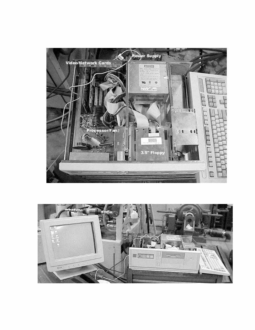

III. Software Documentation
A. Compiler Notes/Batch files
In order to make code in any programming language useful, it must be compiledinto
“machine code” -- binary information understood by the processor. For this reason, acompiler is specific to the architecture of the processor you intend to use it on. Thedevelopment language for the VC51 camera is ANSI C. However, the processor that willbe running your code is not made by Intel, or AMD, and is not x86 compliant. It is aprocessor made specifically to perform Digital Signal Processing (DSP) very efficiently.As the VC51 documentation states, the processor is made by Analog Devices(www.analog.com) and is the model ADSP2181. For this reason, any code you write forthe camera must be cross-linked with the libraries supplied by Analog.
We were able to download them from Analog’s ftp site for free, as well as sourcecode to the ANSI C compiler used everywhere in the world, GCC. (See www.gnu.orgfor more details about gcc.) Each time you compile code for the camera, it must then belinked with a linker provided by Analog Devices. This is currently set up on the harddisk of the system provided to our customer, along with batch files (*.bat) so that tocompile a program one only has to type the name of the batch file followed by the nameof their C source file. E.g:
C:\ADSP\21XX\EXAMPLES\cc pickles
Will compile the source code in ‘pickles.c’, link it against the ADSP2181 librariesand prepare it for export to the camera (converts it to a Motorola standard .msf file).
B. Image Library v2.0 Documentation
The image library documentation is over a hundred pages long and would not addanything to this report. It is just noted here that the documentation will be delivered toour customer at the conclusion of the project.
C. Utilities for working with the VC51
The method of communicating with the camera is through the serial port on thePC (COM1). This is done with a terminal program such as PROCOMM orHyperterminal, both installed on the development PC. The baud rate must be the samefor the program and the camera. When the camera is first powered up, it defaults to 9600bps.
When you connect to the camera, you should see a shell prompt ($). Theenvironment is similar to a Unix-like operating system, but extremely stripped down.Typing ‘he’ or ‘?’ will give you a list of the recognized commands. The operatingsystem is called VC/RT 2.3, which stands for Vision Components/Real Time operating

system, version 2.3. The camera originally came with v2.1 on it, and upgrading it wasnot an easy process, taking well over a day.
The documentation for working with the VC51 is quite complete, and also overone hundred pages, and thus is not included here. The commands are well documentedthere, as well as how to initiate file transfers, etc. There is a graphical shell for workingwith the camera that simplifies uploading and downloading programs to the camera, but itis not complete and does not allow you to transfer pictures from the camera as it claims.This program is provided by Vision Components and is also installed on the developmentcomputer.
D. Code base for Pickle Sorting (Monolithic)
/* ******************************************** *//* *//* University of Delaware *//* Department of Mechanical Engineering *//* MEEG-447/448-98F/99S *//* Team SD09 *//* Nate Smith *//* Pickle Sorting Code *//* *//* ******************************************** */
#include <vcrt.h>#include <vclib.h>#include <cam0.h>#include <def2181.h>#include <macros.h>
/* Declare runtime constants and reserve some memory */#define pgsize (PGSIZE*2) /* two-page */#define RLC_LNG 0x20000L /* maximum RLC length */#define RLC_SCRATCH 0xa0000L /* scratch space for RLC */#define RLC_OBJ 0xd0000L /* RLC object area */
/* Declare Functions used by main() */void setBeltSpeed(int *speed); /* Sets conveyor speed */void setBeltLength(int *lng); /* Dist from camera to air */void setCurvThresh(int *curv); /* Sets thresh for curv */void setTaperThresh(int *taper); /* Sets thresh for taper*/void dispParams(int *bs,
int *bl,int *ct,int *tt); /* Display Function */
void pickleSort(int *speed,int *lng,int *curv,int *taper); /* The hard part */
void terminate(void); /* Ends menu loop */void finish(void); /* Null function */void wait(int time); /* Waits n seconds */
void rdline(char *s, int maxlngth); /* Auxillary read line */
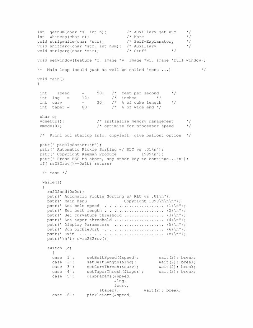
int getnum(char *s, int n); /* Auxillary get num */int whitesp(char c); /* More */void stripwhite(char *str); /* Self-Explanatory */void shiftarg(char *str, int num); /* Auxillary */void striparg(char *str); /* Stuff */
void setwindow(feature *f, image *v, image *w1, image *full_window);
/* Main loop (could just as well be called 'menu'...) */
void main(){
int speed = 50; /* feet per second */ int lng = 12; /* inches */ int curv = 30; /* % of cuke length */ int taper = 80; /* % of wide end */
char c; vcsetup(); /* initialize memory management */ vmode(0); /* optimize for processor speed */
/* Print out startup info, copyleft, give bailout option */
pstr(" pickleSorter:\n"); pstr(" Automatic Pickle Sorting w/ RLC vs .01\n"); pstr(" Copyright Keeman Produce 1999\n"); pstr(" Press ESC to abort, any other key to continue...\n"); if( rs232rcv()==0x1b) return;
/* Menu */
while(1) { rs232snd(0x0c); pstr(" Automatic Pickle Sorting w/ RLC vs .01\n"); pstr(" Main menu Copyright 1999\n\n\n"); pstr(" Set belt speed ......................... (1)\n"); pstr(" Set belt length ........................ (2)\n"); pstr(" Set curvature threshold ................ (3)\n"); pstr(" Set taper threshold .................... (4)\n"); pstr(" Display Parameters ..................... (5)\n"); pstr(" Run pickleSort ......................... (6)\n"); pstr(" Exit .................................. (e)\n"); pstr("\n"); c=rs232rcv();
switch (c) { case '1': setBeltSpeed(&speed); wait(2); break; case '2': setBeltLength(&lng); wait(2); break; case '3': setCurvThresh(&curv); wait(2); break; case '4': setTaperThresh(&taper); wait(2); break; case '5': dispParams(&speed, &lng, &curv,
&taper); wait(2); break; case '6': pickleSort(&speed,

&lng, &curv,
&taper); finish(); break; case '7': terminate(); finish(); break; case 'e': terminate(); return; default: break; } /* End of switch() */
} /* End of while(1) */
} /* End of main() */
/* Begin Auxillary Functions */
void setBeltSpeed(int *speed){ char s[10]; pstr("Set Current Conveyor Belt Speed\n"); pstr("Belt Speed in Feet per Minute = "); rdline(s,5); *speed = getnum(s,10);}
void setBeltLength(int *lng){ char s[10]; pstr("Set Distance from Camera to Ejection Mechanism\n"); pstr("Enter Distance in Inches\n"); rdline(s,5); *lng = getnum(s,5);}
void setCurvThresh(int *curv){ char s[10]; pstr("Set Curvature Threshold Level for 'Crook' Classification\n"); pstr("Enter Curvature as a percentage of Cuke Length\n"); rdline(s,5); *curv = getnum(s,5);}
void setTaperThresh(int *taper){ char s[10]; pstr("Set Taper Threshold Level for 'Nub' Classification\n"); pstr("Enter Taper as a percentage of Cuke Thickness\n"); rdline(s,5); *taper = getnum(s,5);}
void dispParams(int *bs, /* Belt Speed */int *bl, /* Belt Length */int *ct, /* Curve Thresh */int *tt) /* Taper Thresh */
{ pstr("BeltSpeed = "); print("%d", &bs);
pstr(" ft/s \n"); pstr("BeltLength = "); print("%d", &bl); pstr(" inches \n"); pstr("CurvatureThreshold = "); print("%d", &ct); pstr(" % of Length \n"); pstr("TaperThreshold = "); print("%d", &tt); pstr(" % of Width \n");
}
void terminate(void){ pstr("Thanks for using pickleSort!\n");}
void finish() {}
void wait(int time){ int i, j; for(i=0; i<time; i++) { for(j=0; j<20; j++) { while(getvar(vline) != 0); while(getvar(vline) == 0); } }}
void rdline(char *str, int maxlng){ char c; int i=0; while(((c = rs232rcv()) != 0x0d) && (i++ < maxlng)) { rs232snd(c); *str++ = c; } *str = '\0';}
int getnum(char *str,int iscale){register int scale; /* scale to convert numbers */register int final; /* final sum of the expression */register int num; /* temporary number holder */register int sign; /* plus or minus */
scale = iscale; num = 0L;
sign = 1;final = 0;while (!whitesp(str[0]))

{ rs232snd(str[0]); switch (str[0])
{ case '+': final = final + sign * num; num = 0L;
sign = 1;scale = iscale;break;
case '-': final = final + sign * num; num = 0L;
sign = -1;scale = iscale;break;
case '0':case '1':case '2':case '3':case '4':case '5':case '6':case '7':case '8':case '9':
num = num * scale + (str[0] - '0');break;
case 'a':case 'b':case 'c':case 'd':case 'e':case 'f':
num = num * scale + (str[0] - 'a' + 10);break;
case 'A':case 'B':case 'C':case 'D':case 'E':case 'F':
num = num * scale + (str[0] - 'A' + 10);break;
default:return(-1);
}shiftarg(str,1);
} final = final + sign * num; stripwhite(str);
return(final);}
int whitesp(char c) /* see if c is a whitespace character */{

if (c == ' ' || c == '\t' || c == '\n' || c == '\0') return(1);
else return(0);}
/* shift the string str, num characters to the left */
void shiftarg(char *str,int num){register int i;
for (i=0;str[i] != '\0';i++)str[i] = str[i+num];
}
/* strip characters from front of string until nonwhitespace */
void striparg(char *str){register int j ;
for ( j = 0;!whitesp(str[j]); j++);
while(whitesp(str[j])) j++;
shiftarg(str, j);}
void stripwhite(char *str){ while (whitesp(str[0]))
shiftarg(str,1);}
void wait_n(int time){ int i,j; for(i=0;i<time;i++) { for(j=0;j<20;j++) { while(getvar(vline) != 0); while(getvar(vline) == 0); } }}
void setwindow(feature *f, image *v, image *w, image *full){int x, y;long sto = (long)8 * pgsize * getvar(ovpage) - Offset_Overlay;long adr, lst;
x = f->x_center - X_SIZE/2;y = 2*f->y_center - Y_SIZE/2;

adr = w->st + (long)y * (long)(w->pitch / 2) + (long)x;lst = (long)(full->dy - Y_SIZE)*(long)(full->pitch);
if((f->x_min != 0) && (f->x_max != w->dx) /* object must be */ && (f->y_min != 0) && (f->y_max != w->dy) /* completely */ && (adr > 0L) && (adr < lst)) { /* inside of window */ v->st += (long)y * (long)(v->pitch) + (long)x; v->dx = X_SIZE; v->dy = Y_SIZE; w->st = adr; w->dx = X_SIZE; w->dy = Y_SIZE/2; }else { v->st = sto; /* take full window */ v->dx = full->dx; /* for next search */ v->dy = full->dy; w->st = full->st; /* take full window */ w->dx = full->dx; /* for next search */ w->dy = full->dy/2; }
}
/*void pickleSort(int *speed,
int *lng,int *curv,int *taper)
{
/* Constants */long st = 1024L;int dx = getvar(hwidth) * 2 - 8;int dy = 570;int pitch = getvar(vpitch) * 2;int ovp = getvar(ovpage);long sto = (long)8 * pgsize * ovp;long rst, tst;int rx, ry, min, max, avg;int tx, ty, i, thr, x, y;char c=' ';long hist[256];image full_window; /* Full Window */image w1; /* Focus Window */image r_ovl; /* Right Bar */
feature f;
/* Set up memory space */full_window = (image)(st, dx, dy, ptch); /* Full Window */w1 = (image)(sto, dx, dy, ptch); /* Img Memory */
#define rdx 32#define rdy 260

rx = 7*dx/8 - rdx/2; /* X upper left corner*/
ry = (dy - rdy)/2; /* Y upper left corner*/
rst = (long)ry*ptch+(long)rx; /* Of the */r_ovl = (image) (sto + rst, rdx, rdy, ptch); /* Right bar
*/
#define tdx 512#define tdy 64tx = (dx - tdx)/2; /* X upper left corner
*/ty = 7*dy/8 - tdy/2; /* Y upper left corner
*/tst = (long)ty*ptch+(long)tx; /* Of the */text1 = (image) (sto + sts, tdx, tdy, ptch) /* Text Field
*/
dframeo(&r_ovl); /* draw right bar */chprint_ov("pickles version 0.01",&text1,4,4);dmarkerz(&w1);
avg=min=max=0;i=0;
/* Algorithm: *//* ********** *//* 1) Encapsulate routine in a while loop *//* 2) Take pictures continuously, every n *//* milliseconds, binarizing each one, and *//* checking to see if it's a complete pickle*//* until it is. When it is, stop taking *//* taking pictures and analyze the thing. */
/* Hitting esccape will terminate the routine */ while((c = rs232rcv()) != 0x1b) { tpict(); /* Take a picture */ vmode(4); /* Set the video mode */ histo(&w2, hist);
show(&r_ovl,min,1); show(&r_ovl,max,1); show1(&r_ovl,avg,1); calc(hist,(long)w2.dx*w2.dy,&avg,&min,&max); show(&r_ovl,min,1); show(&r_ovl,max,1); show1(&r_ovl,avg,1); thr=(min+max)/2;/* print("min: %d max: %d thr: %d avg: %d\r",min,max,thr,avg);*/ rlcmk(&w2, thr, RLC, SIZE); rlc_feature(&f,RLC,COLOR); dmarkerz(&w); /* clear window */

/* Binarize it
/* Check the picture for a complete pickle -- that is, the */ /* Entire left edge should be white */
setwindow(&f,&w,&w2,&full); y=(int)(2L*w2.st / (long)w2.pitch); x=(int)(w2.st - (long)y * (long)w2.pitch / 2L); if((x>1) && (y>1)) print("x: %d y: %d \r",x+X_SIZE/2,y+Y_SIZE/2); else print("not found \r"); if(i == 200) chprint_ov(" ",&text1,4,4); else if(i == 100) chprint_ov("Senior Design SD09 1999S",&text1,4,4); if(i < 201) i++; dmarkerz(&w); /* draw window */ }}
/* 3) When a complete pickle is found, the pic *//* taken is used for curvature/taper *//* analysis. Timing is critical here. *//* This involves determining the run-length *//* code of the image and labeling the *//* object (cuke) found */
item_start = (item *)vcmalloc(MAXITEM*sizeof(item));clr_ovl(getvar(ovpage));
pstr("tdr: Time Delay Recorder Vs. 1.0\n");pstr("Copyright Vision Components 1998\n\n");pstr("press ESC to abort or any other key to continue\n");if(rs232rcv()==0x1b) return (0);
while(1) { rs232snd(0x0c); pstr("tdr: Time Delay Recorder Vs. 1.0\n"); pstr("main menu Copyright 1998\n\n\n"); pstr("set delay time constant ............... (1)\n"); pstr("set image quality ..................... (2)\n"); pstr("set image resolution .................. (3)\n"); pstr("recording ............................. (4)\n"); pstr("display ............................... (5)\n"); pstr("exit .................................. (e)\n");
pstr("\n"); c=rs232rcv();
switch (c) { case '1': settime(&time); finish(); break; case '2': setqual(&quality); finish(); break; case '3': finish(); break; case '4': i0=jprecord(time, quality); finish(); break; case '5': jpdisp(i0); finish(); break; case 'e': terminate(); return(0); default: break; } }
}
void settime(int *time){char b[10];pstr("set time constant for recording\n");pstr("enter number of seconds between pictures\n");rdline(b,5);*time = getnum(b,10);}
void setqual(int *quality){char b[10];pstr("set image quality for recording\n");pstr("enter quality in percent\n");rdline(b,5);*quality = getnum(b,10);}
item *jprecord(int time, int q){char c=0;image a = {0L, 736, 572, 1024};image txt = {sto+stx, 480, 64, 1024}; /* text field / overlay */image fnr = {sto+stf, 480, 64, 1024}; /* frame no. / overlay */long addr;long jp_strt = JPSTART; /* start address of JPEG */item *i0;int ctr=0;char s[5];
vmode(4); /* live image + overlay */
chprint_ov(" REC ",&txt,5,5);
item_n0=0;item_n1=MAXITEM;
addr = jp_strt;
i0=newitem(ctr++, (item *)0, addr);

while(c != 0x1b) { if(rbempty() != -1) c=rs232rcv(); /* read character */
sprint(s,"%03d",ctr); /* output ctr */ chprint_ov(s,&fnr,5,5); /* to overlay */
tpict(); /* take picture */ vmode(4); /* live + overlay */
addr=cjpeg(&a, q, addr, 0x80000L, (int (*)())wr_circ);
i0 = newitem(ctr++, i0, addr); /* create new item */
elim(i0,addr); /* remove old images */ wait_n(time); /* delay */ }
chprint_ov(" ",&txt,5,5);chprint_ov(" ",&fnr,5,5);vmode(0);
return(i0);}
item *newitem(int n, item *i0, long next){item *i1;
if(item_n1 == item_n0) return((item *)0); /* item buffer full */if(item_n1 >= MAXITEM) item_n1 = 0;
i1=&item_start[item_n1++];i1->number = n;i1->prev = (int *)i0;i1->next = (int *)0;i1->addr = next;
if(i0 != (item *)0) i0->next = (int *)i1;
return(i1);}
void remove_item(){
item_n0++;if(item_n0 >= MAXITEM) item_n0 = 0;}
longcdist(long a1,long a2,long l){

long d = a1-a2;
return((d > 0) ? d : d+l);}
void elim(item *i0, long addr){long jp_strt = JPSTART; /* start address of JPEG */long jp_last = JPLAST; /* last JPEG address */long l = jp_last-jp_strt;item *ix,*iy;long d0,d1;
ix=i0;d0=l;
while(ix != (item *)0) { d1 = cdist(ix->addr,addr,l); if(d1 > d0 ) { remove_item(ix); iy->prev = (int *)0;
} else { d0=d1; iy=ix; } ix = (item *)ix->prev; }
}
item *first(item *i0){item *ix;
ix=i0;
while((item *)ix->prev != (item *)0) { ix = (item *)ix->prev; }return(ix);}
void finish(void){}
void jpdisp(item *i0){image a = {0L, 736, 572, 1024};item *ix;

long next;int n;
vmode(1);
pstr("display\n");
ix = first(i0);
while(ix != (item *)0) { n=ix->number; print("no: %d \r",n);
next=djpeg(&a, ix->addr, (int (*)())rd_circ); ix = (item *)ix->next; }
pstr("finish\n");}
void terminate(void){pstr("thank you for using tdr\n");}
voidwr_circ(emit_ctrl *emc, int val)/* Emit a byte */{long addr=emc->ptr; /* addr ptr DRAM */long jp_strt = JPSTART; /* start address of JPEG */long jp_last = JPLAST; /* last JPEG address */
if(addr <= emc->last) { wpix(val,addr); addr++; if(addr == jp_last) addr = jp_strt; emc->ptr=addr; }else { emc->err=-1; }}
int rd_circ(fill_ctrl *fct){long addr=fct->ptr;int x;long jp_strt = JPSTART; /* start address of JPEG */long jp_last = JPLAST; /* last JPEG address */

x=rpix(addr);addr++;if(addr == jp_last) addr = jp_strt;
fct->ptr=addr;return(x);}
voidrdline(char *str, int maxlng){char c;int i=0;while(((c = rs232rcv()) != 0x0d) && i++ < maxlng) { rs232snd(c); *str++ = c; }*str = '\0';}
intgetnum(char *str,int iscale){register int scale; /* scale to convert numbers */register int final; /* final sum of the expression */register int num; /* temporary number holder */register int sign; /* plus or minus */
scale = iscale; num = 0L;
sign = 1;final = 0;while (!whitesp(str[0])){
rs232snd(str[0]); switch (str[0])
{ case '+': final = final + sign * num; num = 0L;
sign = 1;scale = iscale;break;
case '-': final = final + sign * num; num = 0L;
sign = -1;scale = iscale;break;
case '0':case '1':case '2':case '3':case '4':
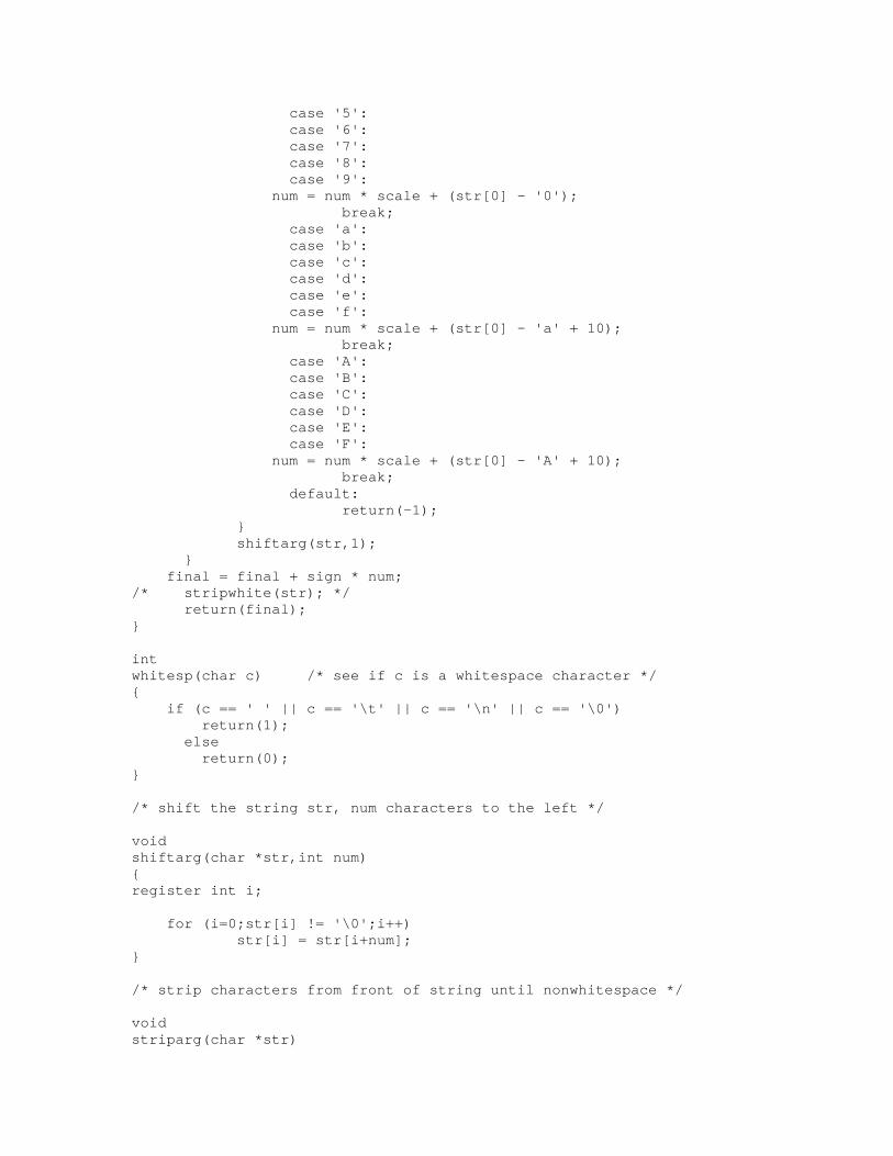
case '5':case '6':case '7':case '8':case '9':
num = num * scale + (str[0] - '0');break;
case 'a':case 'b':case 'c':case 'd':case 'e':case 'f':
num = num * scale + (str[0] - 'a' + 10);break;
case 'A':case 'B':case 'C':case 'D':case 'E':case 'F':
num = num * scale + (str[0] - 'A' + 10);break;
default:return(-1);
}shiftarg(str,1);
} final = final + sign * num;/* stripwhite(str); */
return(final);}
intwhitesp(char c) /* see if c is a whitespace character */{ if (c == ' ' || c == '\t' || c == '\n' || c == '\0') return(1);
else return(0);}
/* shift the string str, num characters to the left */
voidshiftarg(char *str,int num){register int i;
for (i=0;str[i] != '\0';i++)str[i] = str[i+num];
}
/* strip characters from front of string until nonwhitespace */
voidstriparg(char *str)

{register int j ;
for ( j = 0;!whitesp(str[j]); j++);
while(whitesp(str[j])) j++;
shiftarg(str, j);}
voidstripwhite(char *str){ while (whitesp(str[0]))
shiftarg(str,1);}
void wait_n(int time){int i,j;for(i=0;i<time;i++) { for(j=0;j<20;j++) { while(getvar(vline) != 0); while(getvar(vline) == 0); } }}
void clr_ovl(int ovl_page) /* clear overlay*/ /* image size: 740 x 574, pitch 1024*/{image ovl = {(long)pgsize*ovl_page-Offset_Overlay/8, 94, 574, 128};set(&ovl,0);}
/* 4) If the pickle is determined to be bad, *//* then a pulse is sent to the PLC *//* output to remove the pickle *//* 5) If not, then the camera should wait *//* until the next predicted time a new *//* pickle can be in the camera frame, at *//* which point it can resume taking pictures*/
} /* End of while((c=rs232rcv()))} /* End of pickleSort() */*/
/* End Auxillary Functions */
V. Important ContactsTeam Members: Nate Smith [email protected] Alan Starr [email protected] Jon Hackett [email protected] Jim Wert [email protected]
Customer: Ed Kee [email protected]
Advisors: Jim Glancey [email protected] Michael Keefe [email protected]
Vision Components (Camera Design/Manufacture) Michael Schäfer [email protected] (Technical Questions) Marcel Singleton [email protected] (USA Sales Representative)

Acknowledgements
We would like to thank our advisor Dr. James Glancey for his knowledge, use of his lab,and additional miscellaneous parts he donated.
We would also like to thank our sponsor Mr. Ed Kee for sponsoring this project and forthe information regarding the pickle industry.
Thanks also go to Michael Schäfer and Marcel Singleton of Vision Components,Germany for their knowledge and help in the continuing development of the camera.