Embed Size (px)
Citation preview
����������� �� �
Measured Value Displays
User’s Manual
ND 221 B
Titel.pm6 14.07.2004, 08:592
2
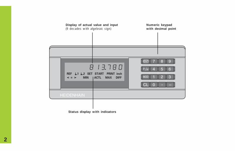
Numeric keypad
with decimal point
Status display with indicators
Display of actual value and input
(9 decades with algebraic sign)
����������
� �
� �
� �
� � ���
������ ��� ����� ���� ��
�� ���� ��� ������ ���
3
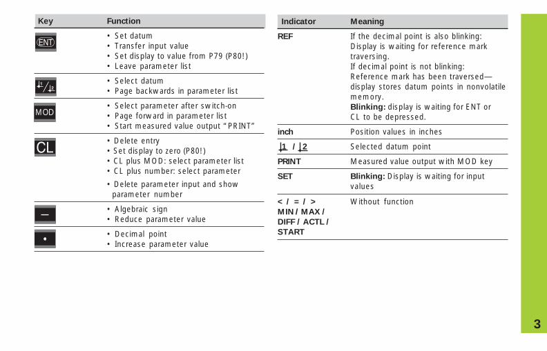
Indicator Meaning
REF If the decimal point is also blinking:Display is waiting for reference marktraversing.If decimal point is not blinking:Reference mark has been traversed—display stores datum points in nonvolatilememory.Blinking: display is waiting for ENT orCL to be depressed.
inch Position values in inches
1 / 2 Selected datum point
PRINT Measured value output with MOD key
SET Blinking: Display is waiting for inputvalues
MOD
Key Function
• Set datum• Transfer input value• Set display to value from P79 (P80!)• Leave parameter list
• Select datum• Page backwards in parameter list
• Select parameter after switch-on• Page forward in parameter list• Start measured value output “PRINT”
• Delete entry• Set display to zero (P80!)• CL plus MOD: select parameter list• CL plus number: select parameter
• Delete parameter input and showparameter number
• Algebraic sign• Reduce parameter value
• Decimal point• Increase parameter value
< / = / > Without functionMIN / MAX /
DIFF / ACTL /
START
4
This manual is for the ND 221 B measured valuedisplay with the following software number orhigher:
349 797-04
The software number is indicated on a label onthe rear panel.
Ite
ms s
up
pli
ed Items supplied with ND 221 B
Measured value display unit,ND 221B benchtop modelEncoder input 11 µAPP Id. Nr. 344 992-xx
Power cord 3 m (9.9 ft)
User's Manual ND 221 B
Adhesive plug-in feet For stacking ND 221B units
5
Installation and Specifications
Rear Panel, Accessories 11
Mounting 12
Power Connection 13
Operating Parameters 14
List of Operating Parameters 16
Linear Encoders 19
Nonlinear Axis Error Compensation 22
Locking the Keypad 26
Displaying the Software Version 27
Distance-to-Go Mode 28
RS-232-C/V.24 Interface (X31) 29
Input and Output of Parameter and 32
Compensation Value Lists
Output Format of the Parameter List 34
Output Format of the Compensation Value Table 37
Remote Operation over the RS-232-C/ V.24 40
Data Interface
Specifications 43
Dimensions 44
Contents
Co
nte
nts
Working with the ND Display Units
Position Encoders and Reference Marks 6
Switch-On, Traversing Reference Marks 7
Datum Setting 8
Measured Value Output 9
Error Messages 10
6
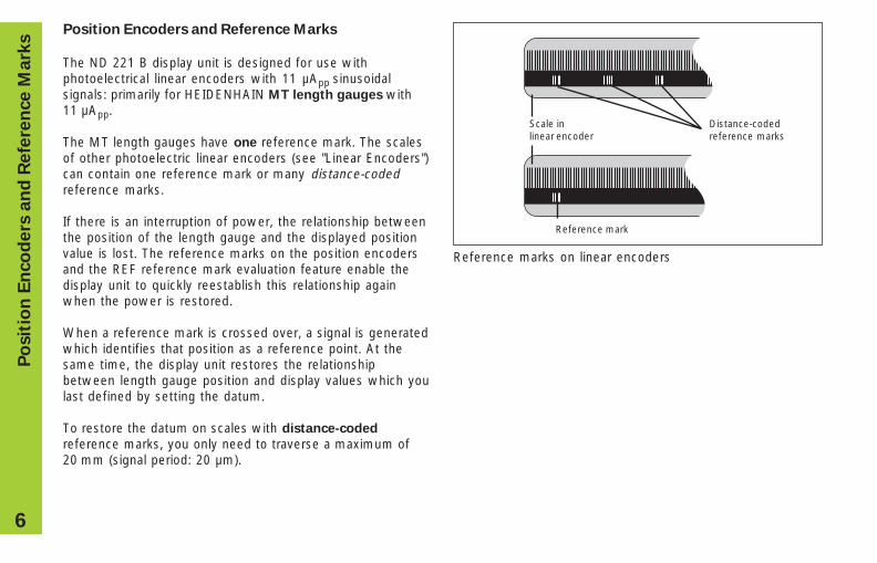
Scale in Distance-codedlinear encoder reference marks
Position Encoders and Reference Marks
The ND 221 B display unit is designed for use withphotoelectrical linear encoders with 11 µApp sinusoidalsignals: primarily for HEIDENHAIN MT length gauges with11 µApp.
The MT length gauges have one reference mark. The scalesof other photoelectric linear encoders (see "Linear Encoders")can contain one reference mark or many distance-codedreference marks.
If there is an interruption of power, the relationship betweenthe position of the length gauge and the displayed positionvalue is lost. The reference marks on the position encodersand the REF reference mark evaluation feature enable thedisplay unit to quickly reestablish this relationship againwhen the power is restored.
When a reference mark is crossed over, a signal is generatedwhich identifies that position as a reference point. At thesame time, the display unit restores the relationshipbetween length gauge position and display values which youlast defined by setting the datum.
To restore the datum on scales with distance-coded
reference marks, you only need to traverse a maximum of20 mm (signal period: 20 µm).
Reference mark
Reference marks on linear encoders
Po
sit
ion
En
co
de
rs a
nd
Re
fere
nce
Ma
rks
7
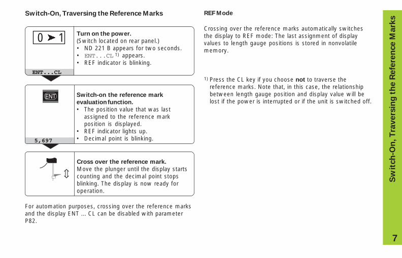
Switch-On, Traversing the Reference Marks REF Mode
Crossing over the reference marks automatically switchesthe display to REF mode: The last assignment of displayvalues to length gauge positions is stored in nonvolatilememory.
1) Press the CL key if you choose not to traverse thereference marks. Note that, in this case, the relationshipbetween length gauge position and display value will belost if the power is interrupted or if the unit is switched off.
Turn on the power.
(Switch located on rear panel.)• ND 221 B appears for two seconds.• ENT...CL 1) appears.• REF indicator is blinking.
Switch-on the reference mark
evaluation function.
• The position value that was lastassigned to the reference markposition is displayed.
• REF indicator lights up.• Decimal point is blinking.
⇔
Cross over the reference mark.
Move the plunger until the display startscounting and the decimal point stopsblinking. The display is now ready foroperation.
5,697
ENT...CL
0 � 1
For automation purposes, crossing over the reference marksand the display ENT ... CL can be disabled with parameterP82.
Sw
itch
-On
, T
ravers
ing
th
e R
efe
ren
ce M
ark
s
8
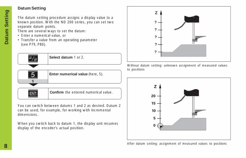
Datum Setting
The datum setting procedure assigns a display value to aknown position. With the ND 200 series, you can set twoseparate datum points.There are several ways to set the datum:• Enter a numerical value, or• Transfer a value from an operating parameter
(see P79, P80).
Select datum 1 or 2.
After datum setting: assignment of measured values to positions
Without datum setting: unknown assignment of measured valuesto positions
Z
?
?
?
?
?
Enter numerical value (here, 5).
5
Datu
m S
ett
ing
Confirm the entered numerical value.
You can switch between datums 1 and 2 as desired. Datum 2can be used, for example, for working with incrementaldimensions.
When you switch back to datum 1, the display unit resumesdisplay of the encoder's actual position.
9
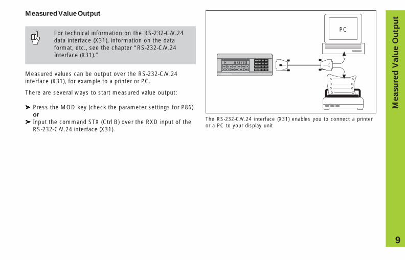
Measured Value Output
For technical information on the RS-232-C/V.24data interface (X31), information on the dataformat, etc., see the chapter “RS-232-C/V.24Interface (X31).”
Measured values can be output over the RS-232-C/V.24interface (X31), for example to a printer or PC.
There are several ways to start measured value output:
� Press the MOD key (check the parameter settings for P86).or
� Input the command STX (Ctrl B) over the RXD input of theRS-232-C/V.24 interface (X31).
HEIDENHAIN
REF 21 SET START PRINT in.
MIN ACTL MAX DIFF=< >
7 8 9
4 5 6
1 2 3
0 . –CL
MOD
PC
Me
asu
red
Va
lue
Ou
tpu
t
The RS-232-C/V.24 interface (X31) enables you to connect a printeror a PC to your display unit
10
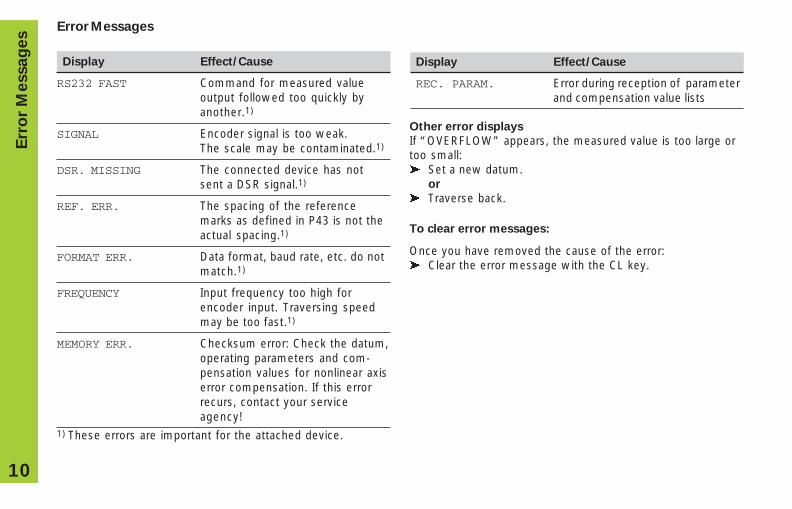
Other error displays
If “OVERFLOW” appears, the measured value is too large ortoo small:� Set a new datum.
or
� Traverse back.
To clear error messages:
Once you have removed the cause of the error:� Clear the error message with the CL key.
Err
or
Messag
es
Error Messages
Display Effect/Cause
RS232 FAST Command for measured valueoutput followed too quickly byanother.1)
SIGNAL Encoder signal is too weak.The scale may be contaminated.1)
DSR. MISSING The connected device has notsent a DSR signal.1)
REF. ERR. The spacing of the referencemarks as defined in P43 is not theactual spacing.1)
FORMAT ERR. Data format, baud rate, etc. do notmatch.1)
FREQUENCY Input frequency too high forencoder input. Traversing speedmay be too fast.1)
MEMORY ERR. Checksum error: Check the datum,operating parameters and com-pensation values for nonlinear axiserror compensation. If this errorrecurs, contact your serviceagency!
1) These errors are important for the attached device.
Display Effect/Cause
REC. PARAM. Error during reception of parameterand compensation value lists
11
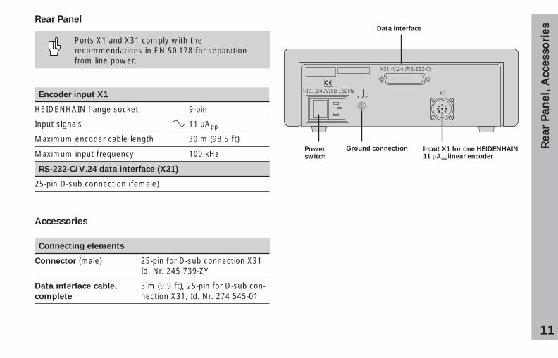
Rear
Pan
el, A
ccesso
ries
Powerswitch
Input X1 for one HEIDENHAIN11 µApp linear encoder
Data interface
Rear Panel
Ports X1 and X31 comply with therecommendations in EN 50 178 for separationfrom line power.
Encoder input X1
HEIDENHAIN flange socket 9-pin
Input signals 11 µApp
Maximum encoder cable length 30 m (98.5 ft)
Maximum input frequency 100 kHz
RS-232-C/V.24 data interface (X31)
25-pin D-sub connection (female)
Accessories
Connecting elements
Connector (male) 25-pin for D-sub connection X31Id. Nr. 245 739-ZY
Data interface cable, 3 m (9.9 ft), 25-pin for D-sub con-complete nection X31, Id. Nr. 274 545-01
Ground connection
12
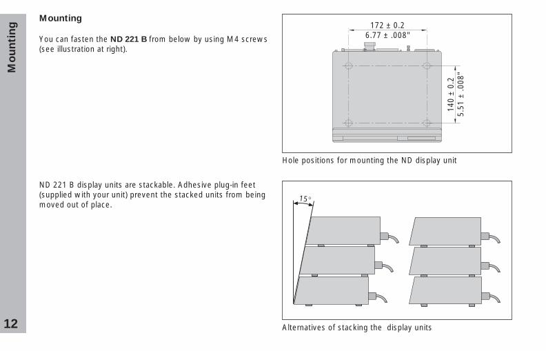
Mounting
You can fasten the ND 221 B from below by using M4 screws(see illustration at right).
Hole positions for mounting the ND display unit
Alternatives of stacking the display units
172 ± 0.26.77 ± .008"
140
± 0
.25.
51 ±
.008
"
ND 221 B display units are stackable. Adhesive plug-in feet(supplied with your unit) prevent the stacked units from beingmoved out of place.
15°
Mo
un
tin
g
13
Power Connection
The rear panel of the ND 221 B contains a connecting jack fora power cord with Euro connector (power cord supplied withthe delivery).
Minimum cross section of the power cord: 0.75 mm2
Power supply: 100 Vac to 240 Vac (–15% to +10%)50 Hz to 60 Hz (± 2 Hz)
A voltage selector is therefore not necessary.
Danger of electrical shock!
Unplug the power cord before opening thehousing. Connect the grounding conductor.Do not interrupt the grounding conductor.
Danger to internal components!
Do not engage or disengage any connections whilethe unit is under power. Use only originalreplacement fuses.
To increase noise immunity, connect the groundterminal on the rear panel to the central groundpoint of the machine.(Minimum cross-section: 6 mm2)
Po
we
r C
on
ne
cti
on
14
Operating Parameters
Operating parameters allow you to modify the operatingcharacteristics of your ND display unit and define theevaluation of the encoder signals.
Operating parameters are designated by:
• the letter P,• a two-digit parameter number, and• an abbreviation.
Example: P01 INCH
The factory settings of the operating parameters areindicated in the parameter list (see “List of OperatingParameters”) in boldface type.
Parameters consist of “user parameters” and “protectedoperating parameters,” which can only be accessed byentering a code number.
User parameters
User parameters are operating parameters that can bechanged without entering the code number:
P00 to P30, P50, P51, P79, P86, P98
The functions of the individual user parameters are detailed inthe list of operating parameters (see “List of OperatingParameters”).
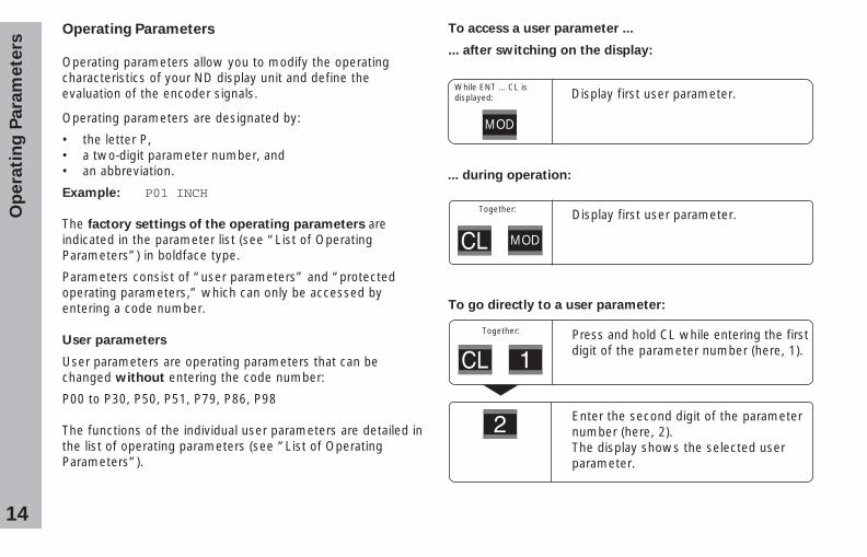
To access a user parameter ...
... after switching on the display:
Display first user parameter.
... during operation:
Display first user parameter.
To go directly to a user parameter:
Press and hold CL while entering the firstdigit of the parameter number (here, 1).
Enter the second digit of the parameternumber (here, 2).The display shows the selected userparameter.
While ENT ... CL isdisplayed:
MOD
Together:
Together:
MOD
Op
era
tin
g P
ara
mete
rs
15
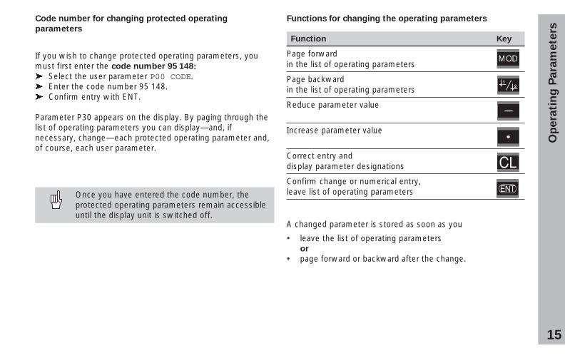
Functions for changing the operating parameters
Function Key
Page forwardin the list of operating parameters
Page backwardin the list of operating parameters
Reduce parameter value
Increase parameter value
Correct entry anddisplay parameter designations
Confirm change or numerical entry,leave list of operating parameters
A changed parameter is stored as soon as you
• leave the list of operating parametersor
• page forward or backward after the change.
MOD
Code number for changing protected operating
parameters
If you wish to change protected operating parameters, youmust first enter the code number 95 148:
� Select the user parameter P00 CODE.� Enter the code number 95 148.� Confirm entry with ENT.
Parameter P30 appears on the display. By paging through thelist of operating parameters you can display—and, ifnecessary, change—each protected operating parameter and,of course, each user parameter.
Once you have entered the code number, theprotected operating parameters remain accessibleuntil the display unit is switched off.
Op
era
tin
g P
ara
mete
rs
16
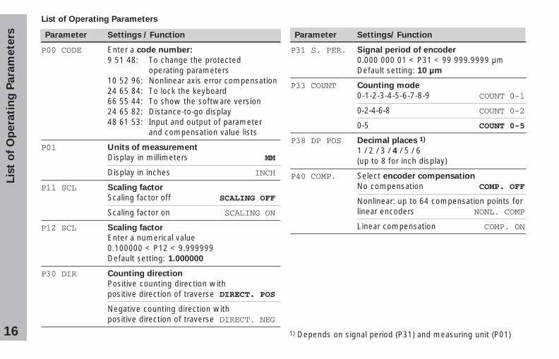
Parameter Settings / Function
P00 CODE Enter a code number:
9 51 48: To change the protectedoperating parameters
10 52 96: Nonlinear axis error compensation24 65 84: To lock the keyboard66 55 44: To show the software version24 65 82: Distance-to-go display48 61 53: Input and output of parameter
and compensation value lists
P01 Units of measurement
Display in millimeters MM
Display in inches INCH
P11 SCL Scaling factor
Scaling factor off SCALING OFF
Scaling factor on SCALING ON
P12 SCL Scaling factor
Enter a numerical value0.100000 < P12 < 9.999999Default setting: 1.000000
P30 DIR Counting direction
Positive counting direction withpositive direction of traverse DIRECT. POS
Negative counting direction withpositive direction of traverse DIRECT. NEG
Lis
t o
f O
pera
tin
g P
ara
mete
rsList of Operating Parameters
Parameter Settings/ Function
P31 S. PER. Signal period of encoder
0.000 000 01 < P31 < 99 999.9999 µmDefault setting: 10 µm
P33 COUNT Counting mode
0-1-2-3-4-5-6-7-8-9 COUNT 0-1
0-2-4-6-8 COUNT 0-2
0-5 COUNT 0-5
P38 DP POS Decimal places 1)
1 / 2 / 3 / 4 / 5 / 6(up to 8 for inch display)
P40 COMP. Select encoder compensation
No compensation COMP. OFF
Nonlinear: up to 64 compensation points forlinear encoders NONL. COMP
Linear compensation COMP. ON
1) Depends on signal period (P31) and measuring unit (P01)
17
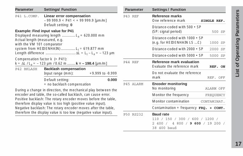
Parameter Settings / Function
P43 REF Reference marks
One reference mark SINGLE REF.
Distance-coded with 500 • SP(SP: signal period) 500 SP
Distance-coded with 1000 • SP(e.g. for HEIDENHAIN LS ...C) 1000 SP
Distance-coded with 2000 • SP 2000 SP
Distance-coded with 5000 • SP 5000 SP
P44 REF Reference mark evaluation
Evaluate the reference mark REF. ON
Do not evaluate the referencemark REF. OFF
P45 ALARM Encoder monitoring
No monitoring ALARM OFF
Monitor the frequency FREQUENCY
Monitor contamination CONTAMINAT.
Contamination + frequency FRQ. + CONT.
P50 RS232 Baud rate
110 / 150 / 300 / 600 / 1200 /2 400 / 4 800 / 9 600 / 19 200 /38 400 baud
Parameter Settings/ Function
P41 L.COMP. Linear error compensation
– 99 999.9 < P41 < + 99 999.9 [µm/m]Default setting: 0
Example: Find input value for P41
Displayed measuring length ............. La = 620.000 mmActual length (measured, e.g.with the VM 101 comparatorsystem from HEIDENHAIN) .............. Lt = 619.877 mmLength difference ............................. ∆L = Lt – La = – 123 µm
Compensation factor k (= P41):k = ∆L / La = – 123 µm / 0.62 m ........k = – 198.4 [µm/m]P42 BKLASH Backlash compensation
Input range (mm): +9.999 to -9.999
Default setting: 0.000
= no backlash compensation
During a change in direction, the mechanical play between theencoder and table, the so-called backlash, can cause error.Positive backlash: The rotary encoder moves before the table,therefore display value is too high (positive value input).Negative backlash: The rotary encoder moves after the table,therefore the display value is too low (negative value input).
Lis
t o
f O
pera
tin
g P
ara
mete
rs
18
Lis
t o
f O
pera
tin
g P
ara
mete
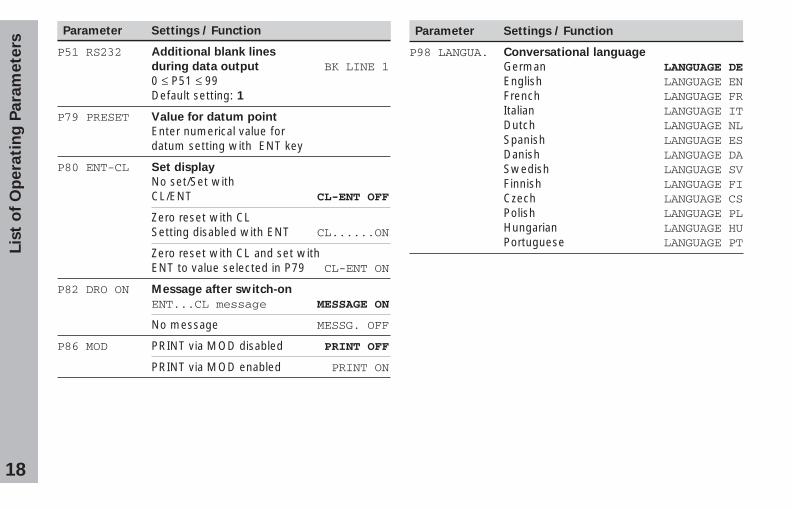
rsParameter Settings / Function
P51 RS232 Additional blank lines
during data output BK LINE 10 ≤ P51 ≤ 99Default setting: 1
P79 PRESET Value for datum point
Enter numerical value fordatum setting with ENT key
P80 ENT-CL Set display
No set/Set withCL/ENT CL-ENT OFF
Zero reset with CLSetting disabled with ENT CL......ON
Zero reset with CL and set withENT to value selected in P79 CL-ENT ON
P82 DRO ON Message after switch-on
ENT...CL message MESSAGE ON
No message MESSG. OFF
P86 MOD PRINT via MOD disabled PRINT OFF
PRINT via MOD enabled PRINT ON
Parameter Settings / Function
P98 LANGUA. Conversational language
German LANGUAGE DEEnglish LANGUAGE ENFrench LANGUAGE FRItalian LANGUAGE ITDutch LANGUAGE NLSpanish LANGUAGE ESDanish LANGUAGE DASwedish LANGUAGE SVFinnish LANGUAGE FICzech LANGUAGE CSPolish LANGUAGE PLHungarian LANGUAGE HUPortuguese LANGUAGE PT
19
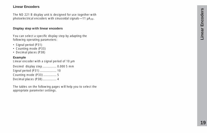
Linear Encoders
The ND 221 B display unit is designed for use together withphotoelectrical encoders with sinusoidal signals—11 µAPP.
Display step with linear encoders
You can select a specific display step by adapting thefollowing operating parameters:
• Signal period (P31)• Counting mode (P33)• Decimal places (P38)
Example
Linear encoder with a signal period of 10 µm
Desired display step ................ 0.000 5 mmSignal period (P31) ................... 10Counting mode (P33) ............... 5Decimal places (P38) ................ 4
The tables on the following pages will help you to select theappropriate parameter settings.
Lin
ear
En
co
ders
20
Lin
ear
En
co
ders
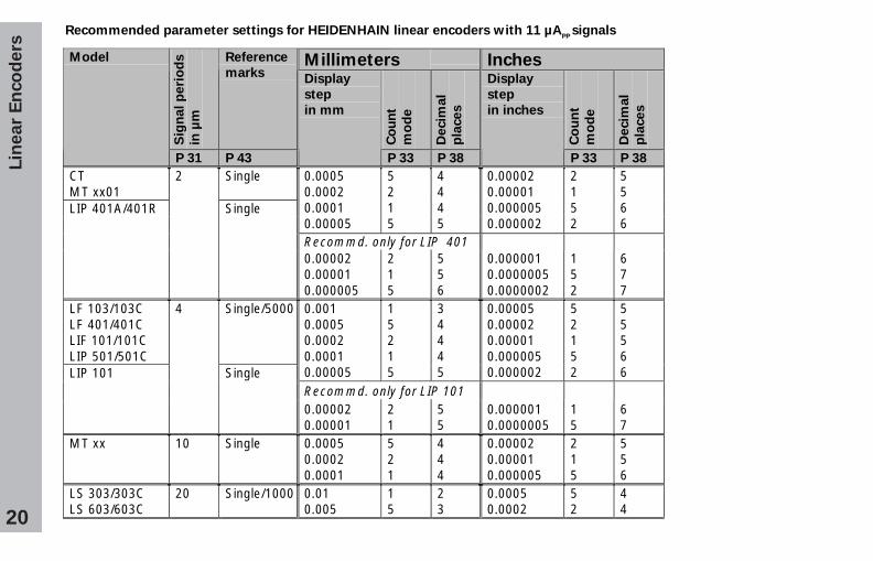
Recommended parameter settings for HEIDENHAIN linear encoders with 11 µAPP
signals
Millimeters Inches
Sig
nal p
eri
od
s
in µ
m
Reference
marks
Co
un
t
mo
de
Decim
al
pla
ces
Co
un
t
mo
de
Decim
al
pla
ces
Model
P 31 P 43
Display
step
in mm
P 33 P 38
Display
step
in inches
P 33 P 38
CTMT xx01
Single 0.00050.00020.00010.00005
5215
4445
0.000020.000010.0000050.000002
2152
5566
Recommd. only for LIP 401
LIP 401A/401R
2
Single
0.000020.000010.000005
215
556
0.0000010.00000050.0000002
152
677
LF 103/103CLF 401/401CLIF 101/101CLIP 501/501C
Single/5000 0.0010.00050.00020.00010.00005
15215
34445
0.000050.000020.000010.0000050.000002
52152
55566
Recommd. only for LIP 101LIP 101
4
Single
0.000020.00001
21
55
0.0000010.0000005
15
67
MT xx 10 Single 0.00050.00020.0001
521
444
0.000020.000010.000005
215
556
LS 303/303CLS 603/603C
20 Single/1000 0.010.005
15
23
0.00050.0002
52
44
21
Lin
ear
En
co
ders
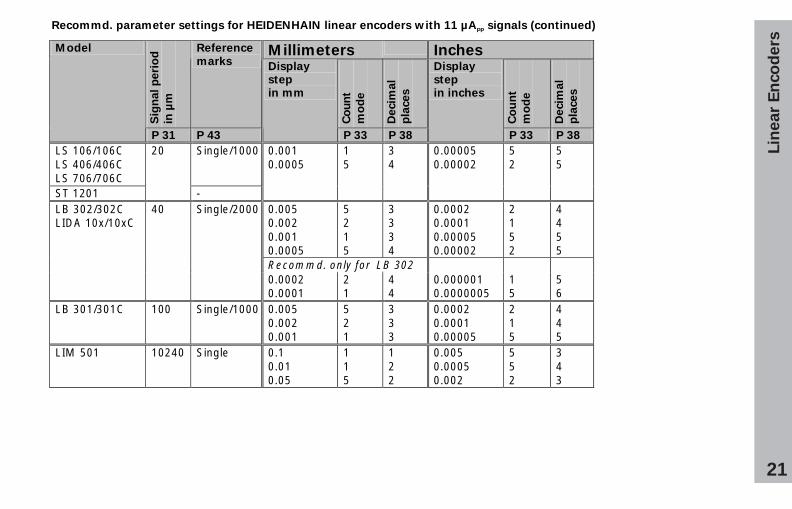
Recommd. parameter settings for HEIDENHAIN linear encoders with 11 µAPP
signals (continued)
Millimeters Inches
Sig
na
l p
eri
od
in µ
m
Reference
marks
Co
un
t
mo
de
De
cim
al
pla
ce
s
Co
un
t
mo
de
De
cim
al
pla
ce
s
Model
P 31 P 43
Display
step
in mm
P 33 P 38
Display
step
in inches
P 33 P 38
LS 106/106C LS 406/406C LS 706/706C
Single/1000
ST 1201
20
-
0.001 0.0005
1 5
3 4
0.00005 0.00002
5 2
5 5
0.005 0.002 0.001 0.0005
5 2 1 5
3 3 3 4
0.0002 0.0001 0.00005 0.00002
2 1 5 2
4 4 5 5
Recommd. only for LB 302
LB 302/302C LIDA 10x/10xC
40 Single/2000
0.0002 0.0001
2 1
4 4
0.000001 0.0000005
1 5
5 6
LB 301/301C 100 Single/1000 0.005 0.002 0.001
5 2 1
3 3 3
0.0002 0.0001 0.00005
2 1 5
4 4 5
LIM 501 10240 Single 0.1 0.01 0.05
1 1 5
1 2 2
0.005 0.0005 0.002
5 5 2
3 4 3
22
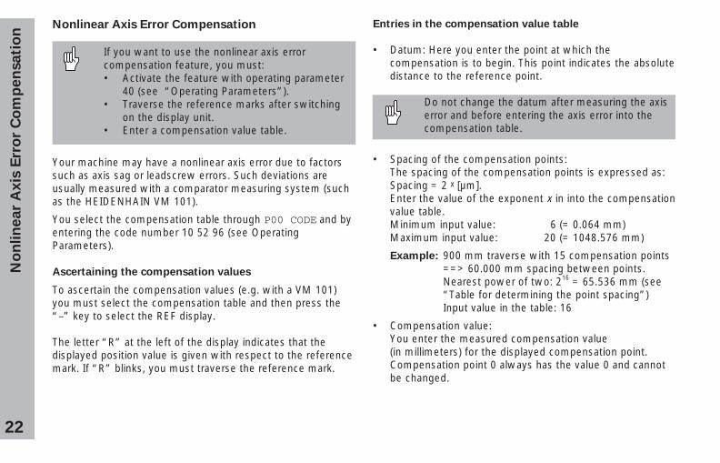
Entries in the compensation value table
• Datum: Here you enter the point at which thecompensation is to begin. This point indicates the absolutedistance to the reference point.
Do not change the datum after measuring the axiserror and before entering the axis error into thecompensation table.
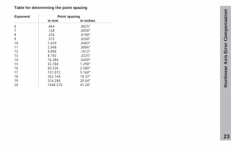
• Spacing of the compensation points:The spacing of the compensation points is expressed as:Spacing = 2 x [µm].Enter the value of the exponent x in into the compensationvalue table.Minimum input value: 6 (= 0.064 mm)Maximum input value: 20 (= 1048.576 mm)
Example: 900 mm traverse with 15 compensation points==> 60.000 mm spacing between points.Nearest power of two: 216 = 65.536 mm (see“Table for determining the point spacing”)Input value in the table: 16
• Compensation value:You enter the measured compensation value(in millimeters) for the displayed compensation point.Compensation point 0 always has the value 0 and cannotbe changed.
Nonlinear Axis Error Compensation
If you want to use the nonlinear axis errorcompensation feature, you must:• Activate the feature with operating parameter
40 (see “Operating Parameters”).• Traverse the reference marks after switching
on the display unit.• Enter a compensation value table.
No
nli
ne
ar
Ax
is E
rro
r C
om
pe
nsa
tio
n
Your machine may have a nonlinear axis error due to factorssuch as axis sag or leadscrew errors. Such deviations areusually measured with a comparator measuring system (suchas the HEIDENHAIN VM 101).
You select the compensation table through P00 CODE and byentering the code number 10 52 96 (see OperatingParameters).
Ascertaining the compensation values
To ascertain the compensation values (e.g. with a VM 101)you must select the compensation table and then press the“–” key to select the REF display.
The letter “R” at the left of the display indicates that thedisplayed position value is given with respect to the referencemark. If “R” blinks, you must traverse the reference mark.
23
No
nli
ne
ar
Ax
is E
rro
r C
om
pe
nsa
tio
n
Table for determining the point spacing
Exponent Point spacing
in mm in inches
6 .064 .0025“7 .128 .0050“8 .256 .0100“9 .512 .0200“10 1.024 .0403“11 2.048 .0806“12 4.096 .1612“13 8.192 .3225“14 16.384 .6450“15 32.768 1.290“16 65.536 2.580“17 131.072 5.160“18 262.144 10.32“19 524.288 20.64“20 1048.576 41.28“
24
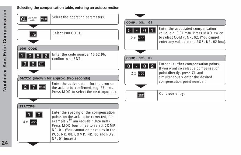
Enter the associated compensationvalue, e.g. 0.01 mm. Press MOD twiceto select COMP. NR. 02. (You cannotenter any values in the POS. NR. 02 box).
Enter all further compensation points.If you want so select a compensationpoint directly, press CL andsimultaneously enter the desiredcompensation point number.
Enter the spacing of the compensationpoints on the axis to be corrected, forexample 210 µm (equals 1.024 mm).Press MOD four times to select COMP.NR. 01. (You cannot enter values in thePOS. NR. 00, COMP. NR. 00 and POS.NR. 01 boxes.)
No
nli
ne
ar
Ax
is E
rro
r C
om
pe
nsa
tio
nSelecting the compensation table, entering an axis correction
DATUM (shown for approx. two seconds)
Enter the active datum for the error onthe axis to be confirmed, e.g. 27 mm.Press MOD to select the next input box.
SPACING
COMP. NR. 01
COMP. NR. 02
Conclude entry.
Select the operating parameters.
P00 CODE
Enter the code number 10 52 96,confirm with ENT.
Select P00 CODE.
together with MOD
MOD
4 x MOD
2 x MOD
2 x MOD
25
No
nli
ne
ar
Ax
is E
rro
r C
om
pe
nsa
tio
n
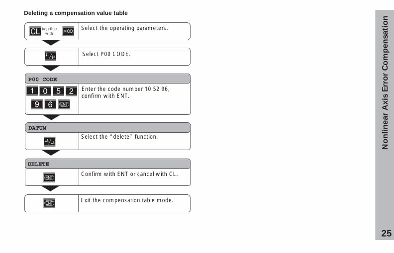
Confirm with ENT or cancel with CL.
Deleting a compensation value table
DATUM
Select the “delete” function.
DELETE
Select the operating parameters.
P00 CODE
Enter the code number 10 52 96,confirm with ENT.
Select P00 CODE.
together with MOD
Exit the compensation table mode.
26
Locking the Keypad
You can disable or re-enable the keypad by entering the codenumber 24 65 84:
➤ Select the user parameter P00 CODE (see “OperatingParameters”).
➤ Enter the code number 24 65 84.
➤ Confirm the entry with ENT.
➤ With the “•” or “–” key, select KEYS ON orKEYS OFF.
➤ Confirm your selection with ENT.
If the keypad is locked, you can only select the datum orselect P00 CODE over the MOD key.
Lo
ck
ing
th
e K
ey
pa
d
27
Displaying the Software Version
To display the software version of the display unit, enter thecode number 66 55 44:
➤ Select the user parameter P00 CODE.
➤ Enter the code number 66 55 44.
➤ Confirm your entry with ENT.
➤ The display unit shows the software number.
➤ With the “–” key you can switch the display to the date ofissue.
➤ To exit the software version display mode, press ENT.
Dis
pla
yin
g t
he S
oft
ware
Vers
ion
28
Dis
tan
ce
-to
-Go
Mo
de
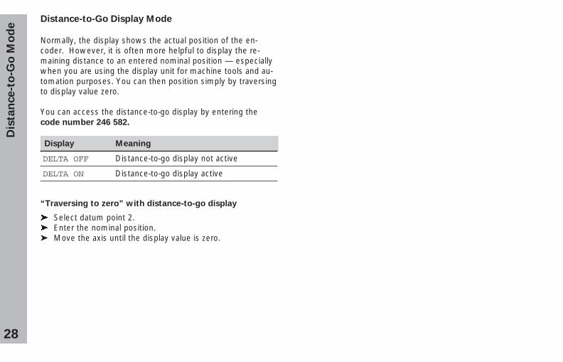
Distance-to-Go Display Mode
Normally, the display shows the actual position of the en-coder. However, it is often more helpful to display the re-maining distance to an entered nominal position — especiallywhen you are using the display unit for machine tools and au-tomation purposes. You can then position simply by traversingto display value zero.
You can access the distance-to-go display by entering thecode number 246 582.
Display Meaning
DELTA OFF Distance-to-go display not active
DELTA ON Distance-to-go display active
“Traversing to zero” with distance-to-go display
� Select datum point 2.� Enter the nominal position.➤ Move the axis until the display value is zero.
29
RS
-232-C
/V.2
4 D
ata
In
terf
ace (
X31)RS-232-C/V.24 Data Interface (X31)
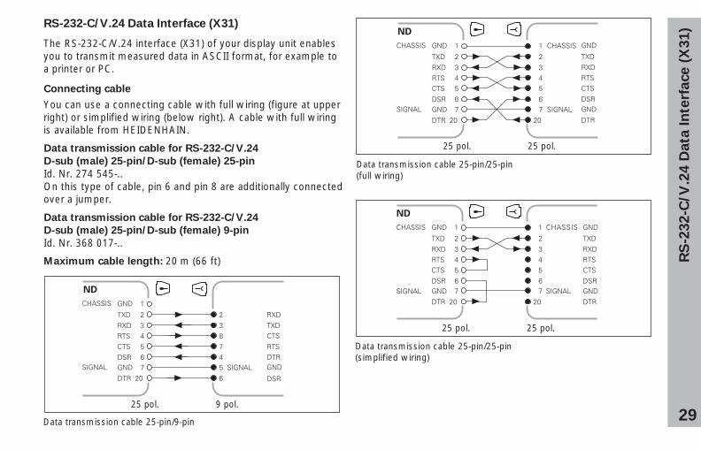
The RS-232-C/V.24 interface (X31) of your display unit enablesyou to transmit measured data in ASCII format, for example toa printer or PC.
Connecting cable
You can use a connecting cable with full wiring (figure at upperright) or simplified wiring (below right). A cable with full wiringis available from HEIDENHAIN.
Data transmission cable for RS-232-C/V.24
D-sub (male) 25-pin/D-sub (female) 25-pin
Id. Nr. 274 545-..On this type of cable, pin 6 and pin 8 are additionally connectedover a jumper.
Data transmission cable for RS-232-C/V.24
D-sub (male) 25-pin/D-sub (female) 9-pin
Id. Nr. 368 017-..
Maximum cable length: 20 m (66 ft)
Data transmission cable 25-pin/9-pin
Data transmission cable 25-pin/25-pin(full wiring)
Data transmission cable 25-pin/25-pin(simplified wiring)
25 pol. 9 pol.
25 pol. 25 pol.
25 pol. 25 pol.
30
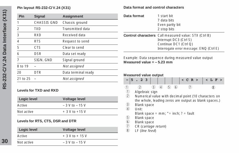
Pin layout RS-232-C/V.24 (X31)
Pin Signal Assignment
1 CHASSIS GND Chassis ground
2 TXD Transmitted data
3 RXD Received data
4 RTS Request to send
5 CTS Clear to send
6 DSR Data set ready
7 SIGN. GND Signal ground
8 to 19 – Not assigned
20 DTR Data terminal ready
21 to 25 – Not assigned
Levels for TXD and RXD
Logic level Voltage level
Active – 3 V to – 15 V
Not active + 3 V to +15 V
Levels for RTS, CTS, DSR and DTR
Logic level Voltage level
Active + 3 V to + 15 V
Not active – 3 V to – 15 V
RS
-232-C
/V.2
4 D
ata
In
terf
ace (
X31)
Data format and control characters
Data format 1 start bit7 data bitsEven parity bit2 stop bits
Control characters Call measured value: STX (Ctrl B)Interrupt DC3 (Ctrl S)Continue DC1 (Ctrl Q)Interrogate error message: ENQ (Ctrl E)
Example: Data sequence during measured value outputMeasured value = – 5.23 mm
Measured value output
– 5 . 2 3 < C R > < L F >
1 2 3 4 5 6 7 81 Algebraic sign2 Numerical value with decimal point (10 characters on
the whole, leading zeros are output as blank spaces.)3 Blank space4 Unit:
Blank space = mm; " = inch; ? = fault5 Blank space6 Blank space7 CR (carriage return)8 LF (line feed)
31
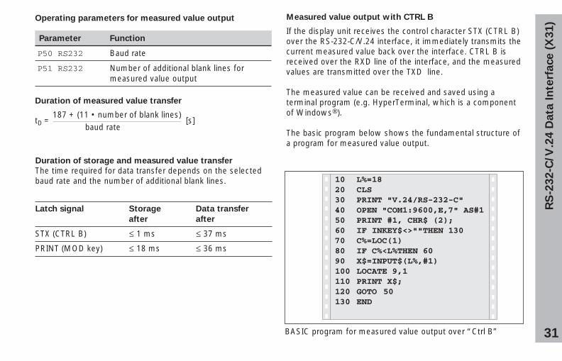
Operating parameters for measured value output
Parameter Function
P50 RS232 Baud rate
P51 RS232 Number of additional blank lines formeasured value output
Duration of measured value transfer
tD = [s]
RS
-232-C
/V.2
4 D
ata
In
terf
ace (
X31)
187 + (11 • number of blank lines)baud rate
Duration of storage and measured value transfer
The time required for data transfer depends on the selectedbaud rate and the number of additional blank lines.
Latch signal Storage Data transfer
after after
STX (CTRL B) � 1 ms � 37 ms
PRINT (MOD key) � 18 ms � 36 ms
Measured value output with CTRL B
If the display unit receives the control character STX (CTRL B)over the RS-232-C/V.24 interface, it immediately transmits thecurrent measured value back over the interface. CTRL B isreceived over the RXD line of the interface, and the measuredvalues are transmitted over the TXD line.
The measured value can be received and saved using aterminal program (e.g. HyperTerminal, which is a componentof Windows®).
The basic program below shows the fundamental structure ofa program for measured value output.
BASIC program for measured value output over “Ctrl B”
10 L%=18 20 CLS 30 PRINT "V.24/RS-232-C" 40 OPEN "COM1:9600,E,7" AS#1 50 PRINT #1, CHR$ (2); 60 IF INKEY$<>""THEN 130 70 C%=LOC(1) 80 IF C%<L%THEN 60 90 X$=INPUT$(L%,#1) 100 LOCATE 9,1 110 PRINT X$; 120 GOTO 50 130 END
32
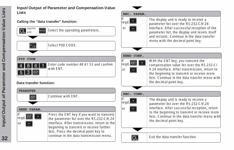
Input/Output of Parameter and Compensation-Value
Lists
Calling the "data transfer" function:
Select the operating parameters. together
with
Select P00 CODE.
P00 CODE
MOD
Enter code number 48 61 53 and confirmwith ENT.
Data transfer function:
TRANSFER
SEND PARAM.
or
Continue with ENT.
Press the ENT key if you want to transmitthe parameter list over the RS-232-C/V.24interface. After transmission, return to thebeginning to transmit or receive furtherlists. Press the decimal point key tocontinue in the data transmission menu.
REC. PARAM.
The display unit is ready to receive aparameter list over the RS-232-C/V.24interface. After successful reception of theparameter list, the display unit resets itselfand restarts. Continue in the data transfermenu with the decimal point key.
ifreqd.
or
SEND COMP.
With the ENT key, you transmit thecompensation value list over the RS-232-C/V.24 interface. After transmission, return tothe beginning to transmit or receive morelists. Continue in the data transfer menu withthe decimal point key.
REC. COMP.
The display unit is ready to receive aparameter list over the RS-232-C/V.24interface. After successful reception, returnto the beginning to transmit or receive morelists. Continue in the data transfer menu withthe decimal point key.
ifreqd.
or
Exit the data transfer function.
Inp
ut/
Ou
tpu
t o
f P
ara
mete
r an
d C
om
pen
sati
on
-Valu
e L
ists
ifreqd.
ifreqd.or
33
Note on the input/output of parameter and
compensation-value lists
With a terminal program (e.g. HyperTerminal, included withWindows®), you can receive the lists output by the displayunit over the RS-232-C/V.24 interface as text files and savethem on your PC. Each list must be saved as a separate textfile. You can then use the terminal program to transmit thetext files back to the display unit .
If you wish, you can edit the text files with a text editor andchange the parameter values, for example. However, thisrequires knowledge of the different output format of the lists(see following pages). When receiving lists, the display unitexpects the same list structure as used for the output.
When receiving lists, the display unit first waits for the startingcharacter < * >. The receiving mode ends as soon as thedisplay unit has received the final character < * >.
The lists received are first checked for the type of display unit(line 2 of output list). The receiving display unit accepts onlylists prepared by the same type of display unit. Furthermore,the list is checked for completeness. Lists that contain, forexample, too many or too few parameters are ignored. If anerror occurs, the following error message appears:
REC. ERROR
To clear the error message, press the CL key.
If the display unit receives invalid parameter values, it sets therespective operating parameter to the default setting.Example: “P01 INCH = INCH = 3”The value 3 is not allowed. The parameter P01 is set to thedefault setting “P01 MM = MM = 0”.
Inp
ut/
Ou
tpu
t o
f P
ara
mete
r an
d C
om
pen
sati
on
-Valu
e L
ists
34
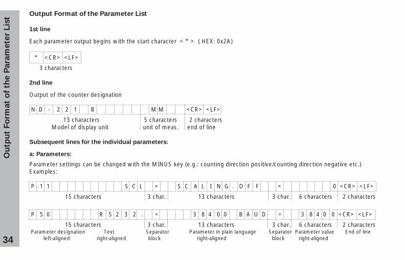
Output Format of the Parameter List
1st line
Each parameter output begins with the start character < * > ( HEX: 0x2A)
* <CR> <LF>
3 characters
2nd line
Output of the counter designation
N D - 2 2 1 B M M <CR> <LF>
13 characters 5 characters 2 characters Model of display unit unit of meas. end of line
Subsequent lines for the individual parameters:
a: Parameters:
Parameter settings can be changed with the MINUS key (e.g.: counting direction positive/counting direction negative etc.)Examples:
P 1 1 S C L = S C A L I N G . O F F = 0 <CR> <LF>
15 characters 3 char. 13 characters 3 char. 6 characters 2 characters
P 5 0 R S 2 3 2 . = 3 8 4 0 0 B A U D = 3 8 4 0 0 <CR> <LF>
15 characters 3 char. 13 characters 3 char. 6 characters 2 characters Parameter designation Text Separator Parameter in plain language Separator Parameter value End of line left-aligned right-aligned block right-aligned block right-aligned
Ou
tpu
t Fo
rmat
of
the P
ara
mete
r Lis
t
35
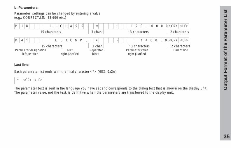
b: Parameters:
Parameter settings can be changed by entering a value(e.g.: CORRECT.LIN. 13.600 etc.)
P 1 8 L . C L A S S . = + 1 2 0 . 0 0 0 0 <CR> <LF>
15 characters 3 char. 13 characters 2 characters
P 4 1 L . C O M P . = - 1 4 0 0 . 0 <CR> <LF>
15 characters 3 char. 13 characters 2 characters Parameter designation Text Separator Parameter value End of line left-justified right-justified block right-justified
Last line:
Each parameter list ends with the final character <*> (HEX: 0x2A)
* <CR> <LF>
The parameter text is sent in the language you have set and corresponds to the dialog text that is shown on the display unit.The parameter value, not the text, is definitive when the parameters are transferred to the display unit.
Ou
tpu
t Fo
rmat
of
the P
ara
mete
r Lis
t
36
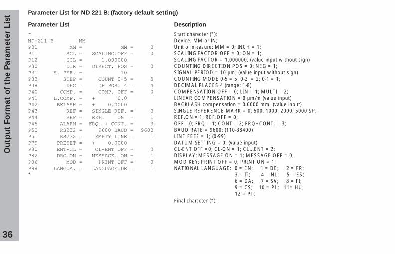
Parameter List for ND 221 B: (factory default setting)
Parameter List Description
� Start character (*);���������������� Device; MM or IN;���������������������������� � Unit of measure: MM = 0; INCH = 1;����������� ������� ������������ � SCALING FACTOR OFF = 0; ON = 1;����������� ������������������ SCALING FACTOR = 1.000000; (value input without sign)���������������������������� �� � COUNTING DIRECTION POS = 0; NEG = 1;������� ��������������������� SIGNAL PERIOD = 10 µm; (value input without sign)���������� �������������������� � COUNTING MODE 0-5 = 5; 0-2 = 2; 0-1 = 1;������������������������ ����� � DECIMAL PLACES 4 (range: 1-8)���������������������������� � COMPENSATION OFF = 0; LIN = 1; MULTI = 2;���������������������������� LINEAR COMPENSATION = 0 µm/m (value input)������������ ���������������� BACKLASH compensation = 0.0000 mm (value input)������������������� ������������ � SINGLE REFERENCE MARK = 0; 500; 1000; 2000; 5000 SP;�������������������������������� � REF.ON = 1; REF.OFF = 0;�������������������!����������� � OFF= 0; FRQ.= 1; CONT.= 2; FRQ+CONT. = 3;���������� ����������"#��������� �"#�� BAUD RATE = 9600; (110-38400)���������� �����������$������� � LINE FEES = 1; (0-99)%"�������� ������������������ DATUM SETTING = 0; (value input)�������������������������������� � CL-ENT OFF =0; CL-ON = 1; CL...ENT = 2;�������������������� ��������� � DISPLAY: MESSAGE.ON = 1; MESSAGE.OFF = 0;�#���������������������������� � MOD KEY: PRINT OFF = 0; PRINT ON = 1;"������������������������������� � NATIONAL LANGUAGE: 0 = EN; 1 = DE; 2 = FR;* 3 = IT; 4 = NL; 5 = ES;
6 = DA; 7 = SV; 8 = FI;9 = CS; 10 = PL; 11= HU;12 = PT;
Final character (*);
Ou
tpu
t Fo
rmat
of
the P
ara
mete
r Lis
t
37
Ou
tpu
t F
orm
at
of
the
Co
mp
en
sa
tio
n V
alu
e T
ab
le
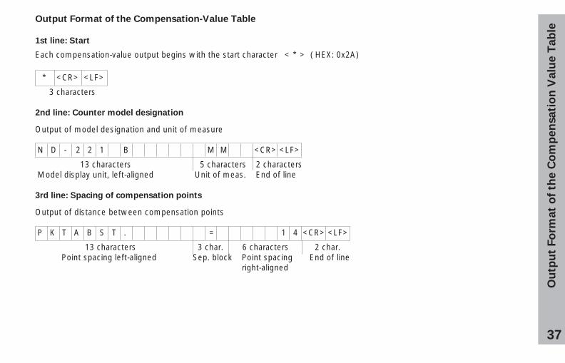
Output Format of the Compensation-Value Table
1st line: Start
Each compensation-value output begins with the start character < * > ( HEX: 0x2A)
* <CR> <LF>
3 characters
2nd line: Counter model designation
Output of model designation and unit of measure
N D - 2 2 1 B M M <CR> <LF>
13 characters 5 characters 2 characters Model display unit, left-aligned Unit of meas. End of line
3rd line: Spacing of compensation points
Output of distance between compensation points
P K T A B S T . = 1 4 <CR> <LF>
13 characters 3 char. 6 characters 2 char. Point spacing left-aligned Sep. block Point spacing End of line right-aligned
38
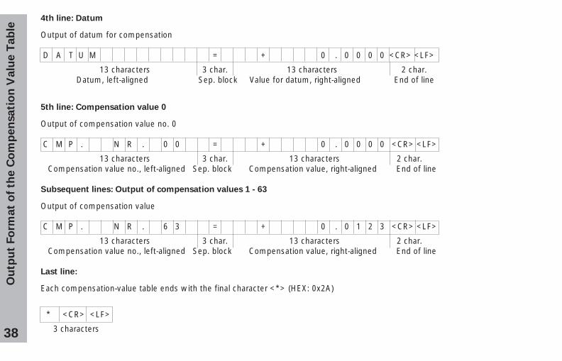
4th line: Datum
Output of datum for compensation
D A T U M = + 0 . 0 0 0 0 <CR> <LF>
13 characters 3 char. 13 characters 2 char. Datum, left-aligned Sep. block Value for datum, right-aligned End of line
5th line: Compensation value 0
Output of compensation value no. 0
C M P . N R . 0 0 = + 0 . 0 0 0 0 <CR> <LF>
13 characters 3 char. 13 characters 2 char. Compensation value no., left-aligned Sep. block Compensation value, right-aligned End of line
Subsequent lines: Output of compensation values 1 - 63
Output of compensation value
C M P . N R . 6 3 = + 0 . 0 1 2 3 <CR> <LF>
13 characters 3 char. 13 characters 2 char. Compensation value no., left-aligned Sep. block Compensation value, right-aligned End of line
Last line:
Each compensation-value table ends with the final character <*> (HEX: 0x2A)
Ou
tpu
t F
orm
at
of
the
Co
mp
en
sa
tio
n V
alu
e T
ab
le
* <CR> <LF>
3 characters
39
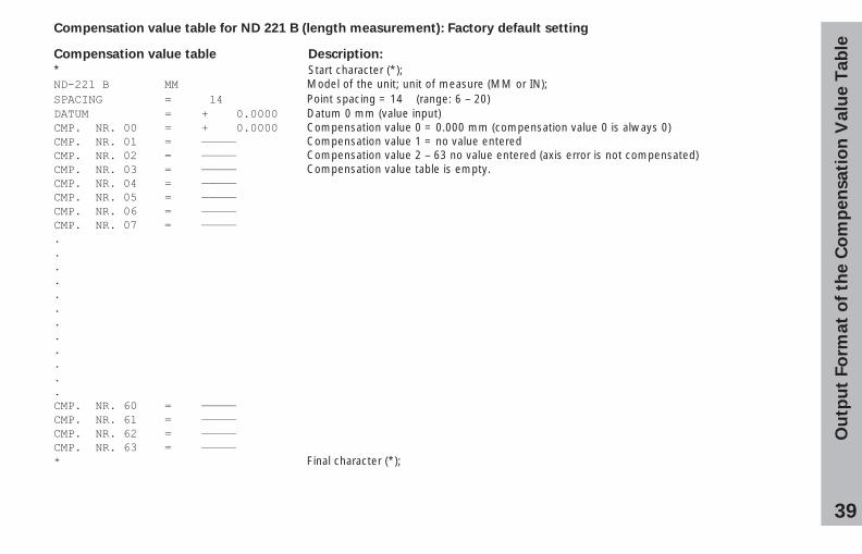
Compensation value table for ND 221 B (length measurement): Factory default setting
Compensation value table Description:
* Start character (*);�������� Model of the unit; unit of measure (MM or IN); ����� � ��� Point spacing = 14 (range: 6 – 20)���� � ����������� Datum 0 mm (value input)���������� � ����������� Compensation value 0 = 0.000 mm (compensation value 0 is always 0)���������� � &&&&& Compensation value 1 = no value entered���������� � &&&&& Compensation value 2 – 63 no value entered (axis error is not compensated)���������� � &&&&& Compensation value table is empty.���������� � &&&&&���������� � &&&&&���������# � &&&&&���������% � &&&&&��������������������#� � &&&&&��������#� � &&&&&��������#� � &&&&&��������#� � &&&&&� Final character (*);
Ou
tpu
t F
orm
at
of
the
Co
mp
en
sa
tio
n V
alu
e T
ab
le
40
Rem
ote
Op
era
tio
n o
ver
the R
S-2
32-C
/V.2
4 D
ata
In
terf
ace
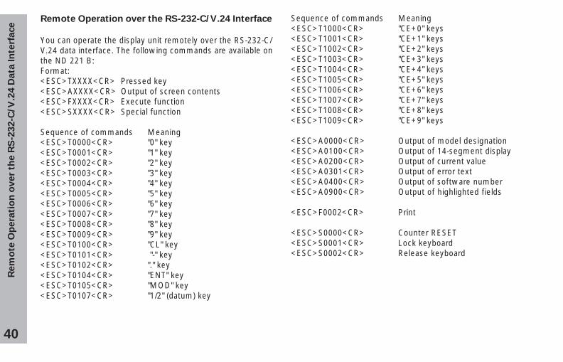
Remote Operation over the RS-232-C/V.24 Interface
You can operate the display unit remotely over the RS-232-C/V.24 data interface. The following commands are available onthe ND 221 B:Format:<ESC>TXXXX<CR> Pressed key<ESC>AXXXX<CR> Output of screen contents<ESC>FXXXX<CR> Execute function<ESC>SXXXX<CR> Special function
Sequence of commands Meaning<ESC>T0000<CR> "0" key<ESC>T0001<CR> "1" key<ESC>T0002<CR> "2" key<ESC>T0003<CR> "3" key<ESC>T0004<CR> "4" key<ESC>T0005<CR> "5" key<ESC>T0006<CR> "6" key<ESC>T0007<CR> "7" key<ESC>T0008<CR> "8" key<ESC>T0009<CR> "9" key<ESC>T0100<CR> "CL" key<ESC>T0101<CR> "-" key<ESC>T0102<CR> "." key<ESC>T0104<CR> "ENT" key<ESC>T0105<CR> "MOD" key<ESC>T0107<CR> "1/2" (datum) key
Sequence of commands Meaning<ESC>T1000<CR> "CE+0" keys<ESC>T1001<CR> "CE+1" keys<ESC>T1002<CR> "CE+2" keys<ESC>T1003<CR> "CE+3" keys<ESC>T1004<CR> "CE+4" keys<ESC>T1005<CR> "CE+5" keys<ESC>T1006<CR> "CE+6" keys<ESC>T1007<CR> "CE+7" keys<ESC>T1008<CR> "CE+8" keys<ESC>T1009<CR> "CE+9" keys
<ESC>A0000<CR> Output of model designation<ESC>A0100<CR> Output of 14-segment display<ESC>A0200<CR> Output of current value<ESC>A0301<CR> Output of error text<ESC>A0400<CR> Output of software number<ESC>A0900<CR> Output of highlighted fields
<ESC>F0002<CR> Print
<ESC>S0000<CR> Counter RESET<ESC>S0001<CR> Lock keyboard<ESC>S0002<CR> Release keyboard
41
Rem
ote
Op
era
tio
n o
ver
the R
S-2
32-C
/V.2
4 D
ata
In
terf
ace
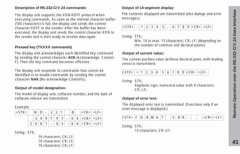
Description of RS-232-C/V.24 commands:
The display unit supports the XON-XOFF protocol whenexecuting commands. As soon as the internal character buffer(100 characters) is full, the display unit sends the controlcharacter XOFF to the sender. After the buffer has beenexecuted, the display unit sends the control character XON tothe sender and is then ready to receive data again.
Pressed key (TXXXX commands)
The display unit acknowledges each identified key commandby sending the control character ACK (Acknowledge Control-F). Then the key command becomes effective.
The display unit responds to commands that cannot beidentified or to invalid commands by sending the controlcharacter NAK (No acknowledge Control-U).
Output of model designation:
The model of display unit, software number, and the date ofsoftware release are transmitted.
Example: <STX> N D - 2 2 1 B <CR> <LF>
3 4 9 7 9 7 - 0 4 <CR> <LF> 2 0 0 1 - 0 5 - 0 4 <CR> <LF>
String: STX;10 characters; CR; LF;10 characters; CR; LF;10 characters; CR; LF;
Output of 14-segment display:
The contents displayed are transmitted (also dialogs and errormessages).
<STX> - 1 2 3 4 5 . 6 7 8 9 <CR> <LF>
Output of current value:
The current position value (without decimal point, with leadingzeros) is transmitted.
<STX> + 1 2 3 4 5 6 7 8 9 <CR> <LF>
String: STX;Algebraic sign; numerical value with 9 characters;CR; LF;
Output of error text:
The displayed error text is transmitted. (Functions only if anerror message is displayed.)
<STX> F O R M A T E R R . <CR> <LF>
String: STX;13 characters; CR; LF;
String: STX;Min. 10 to max. 13 characters; CR; LF; (depending onthe number of commas and decimal points)

42
Rem
ote
Op
era
tio
n o
ver
the R
S-2
32-C
/V.2
4 D
ata
In
terf
ace
Output of software number:
The current software number is transmitted.
<STX> 3 4 9 7 9 7 - 0 4 <CR> <LF>
String: STX;10 characters; CR; LF;
Output of status indicators:
The condition of the status display is transmitted.Example:0 = Status indicator dark1 = Status indicator glows2 = Status indicator blinks
<STX> 0 1 0 0 1 0 0 0 0 0 0 0 0 0 <CR><LF>
a b c d e f g
String: STX;14 characters; CR; LF;
a = REF (reference point)b = datum 1c = datum 2d = SET (set datum)f = PRINT (data output)g = inch (inch display)
Execute functions (FXXX commands):
The display unit acknowledges every correctly receivedcommand by transmitting the control character ACK
(Acknowledge, Control F). Then it executes the command. Itanswers unrecognized or invalid commands by sending thecontrol character NAK (No acknowledge Control U).
Output of the current measured value. The measured value(string) is transmitted as described in the manual (page 30).Same function as calling the measured value with STX(Control B).
Special functions (SXXX commands):
Counter RESET:
The software resets the counter and the counter restarts.(Function same as switching the display unit off and on.)
Locking the keypad:
The display unit acknowledges the special function by sendingthe control character ACK (acknowledge). All keys of thedisplay unit are locked. Now the counter can be operatedonly over the external RS-232-C/V.24 interface and X41.The keyboard can be unlocked either by sending the specialfunction "Unlock keyboard" or by switching the display unitoff and on.
Unlocking the keypad:
The display unit acknowledges the special function by sendingthe control character ACK (acknowledge). This unlocks akeyboard that has been locked with the special function "Lockkeyboard."
43
Sp
ecif
ica
tio
ns
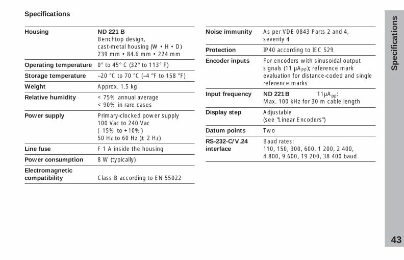
Specifications
Housing ND 221 B
Benchtop design,cast-metal housing (W • H • D)239 mm • 84.6 mm • 224 mm
Operating temperature 0° to 45° C (32° to 113° F)
Storage temperature –20 °C to 70 °C (–4 °F to 158 °F)
Weight Approx. 1.5 kg
Relative humidity < 75% annual average< 90% in rare cases
Power supply Primary-clocked power supply100 Vac to 240 Vac(–15% to +10%)50 Hz to 60 Hz (± 2 Hz)
Line fuse F 1 A inside the housing
Power consumption 8 W (typically)
Electromagnetic
compatibility Class B according to EN 55022
Noise immunity As per VDE 0843 Parts 2 and 4,severity 4
Protection IP40 according to IEC 529
Encoder inputs For encoders with sinusoidal outputsignals (11 µAPP); reference markevaluation for distance-coded and singlereference marks
Input frequency ND 221B 11µApp:Max. 100 kHz for 30 m cable length
Display step Adjustable(see "Linear Encoders")
Datum points Two
RS-232-C/V.24 Baud rates:interface 110, 150, 300, 600, 1 200, 2 400,
4 800, 9 600, 19 200, 38 400 baud
44
Sp
ecif
ica
tio
ns
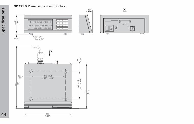
ND 221 B: Dimensions in mm/inches
35 1.43
"
172 ± 0.26.77" ± .008"
33.51.37"
224
8.82
"
140
± 0.
25.
51" ±
.008
"
2399.41"
325
12.8
"
X
��� � ��� ����� ���� � ������� � ���� ��� ���
45350 273-23 · SW 349 797-04 · 10 · 5/2003 · E · Printed in Germany · Subject to change without notice
HEIDENHAIN (G.B.) Limited200 London Road, Burgess HillWest Sussex RH15 9RD, Great Britain� (01444) 247711� (01444) 870024
����������������� �������������� ��� ������������������������� ������� ���������������� ������������������ � � !�"� ��� ��
�������� �!�""#�� � ������������������$��!����%�!�!���! � ������������������
��� � ���# $�����%&&���"� ��� ���&�!�""#�� � ������������������
��� � ���# $�$��%&&���"� ��� ��&�"�#%������% � ������������������
��� � ���# $�$�&'�"� ��� ��'(&�"�#%������% � �����������������(
��� � ���# $�&�$"� ��� ��(������#���# ! � �����)������(�����
��� � ���# $���!"� ��� ��
***�� ��� ��


![PARTE DIARIO - chfutaleufu.com.ar · PARTE DIARIO Estaciones Meteorologicas Lluvia Diaria [mm] Lluvia Mensual [mm] ... ND 5.1 ND ND ND ND 12.8 ND ND ND (Lago Futalaufquen) (Pto Rios)](https://img.pdfslide.net/doc/110x75/5c0da76209d3f23c2a8bb4cf/parte-diario-parte-diario-estaciones-meteorologicas-lluvia-diaria-mm-lluvia.jpg)