Embed Size (px)
Citation preview
Independent Testing - For End User Confidence
QUALIFICATION TESTING OFUNSCREENED CATEGORY 6 ISO/IEC, EN & TIA/EIA CONNECTING HARDWARE
ACCORDING TO REQUIREMENTS OF2 EDITION ISO/IEC 11801, CENELEC EN 50173-1,ND
ANSI/TIA/EIA-568-B.2-1 AND IEC 60603-7-4
Produced byTelebox Industries Corp.
Unscreened Keystone Jack, Category 6, RJ 45Telebox Industries Corp. Identification, P/N TA8761Ux
Prepared by Poul Villien
Project No. 1071660 2007.10.22

Page 2 of 34
3P Project No. 1071660
TABLE OF CONTENTS PAGE
1. IDENTIFICATION 3
2. SURVEY OVER THE WORK 4
3. APPLIED SPECIFICATIONS 5
4. CONDITIONS OF TESTING 6
4.1 Connecting Hardware Types covered by the Qualification Testing 64.2 Electrical Measurements 6
5. FACTORY INSPECTION 7
5.1 Company Organization 75.2 Quality Assurance 95.3 Production Facilities at Telebox Industries Corp. 95.4 Final Testing at Telebox Industries Corp. 10
6. SUMMARISED TEST RESULTS 12
6.1 De-Embedded NEXT Values of Applied RJ 45 Plugs 126.2 Return Loss 136.3 Attenuation 146.4 Near End Crosstalk 146.5 Far End Crosstalk 156.6 Input to Output Resistance 166.7 Input to Output Resistance Unbalance 176.8 Current Carrying Capacity 176.9 Propagation Delay 176.10 Delay Skew 186.11 Electromagnetic Performance 186.12 Balance Measured as Transverse Conversion Loss (TCL) 196.13 Insulation Resistance 206.14 Voltage Proof 20
7. CONCLUSION 21
8. APPENDIX: Data Sheets of Transmission Performance versus Frequency 22

Page 3 of 34
3P Project No. 1071660
1. IDENTIFICATION
Project No.: 1071660
Subject: Qualification Testing of Unscreened Category 6ISO/IEC, EN & TIA/EIA Connecting Hardwareaccording to Requirements of 2 Editionnd
ISO/IEC 11801, CENELEC EN 50173-1,ANSI/TIA/EIA-568-B.2-1 and IEC 60603-7-4
Connecting Hardware: Unscreened, Category 6, RJ 45, Keystone Jack
Manufacturer: Telebox Industries Corp.4F, No. 306, Tatung Road, Sec. 1Hsichih-Taipei 221TaiwanR.O.C.
Telebox Industries Corp. Identification: P/N TA8761Ux
PCB Marking: 001-87604 C6 A01 1F00
Prepared by: 3P Third Party TestingAgern Allé 3DK-2970 HoersholmDenmark
Email: [email protected]: + 45 45572200Fax: + 45 45765708Homepage: www.3Ptest.dk
Author: Poul Villien

Page 4 of 34
3P Project No. 1071660
2. SURVEY OF THE WORK
3P has performed qualification testing on samples of unscreened Category 6 keystone jack fromTelebox Industries Corp., P/N TA8761Ux. Samples of the keystone jack have been supplied fortesting at 3P by Telebox Industries Corp. in August 2007.
Qualification testing of the supplied samples was carried out in September and October, 2007.
Testing has included a verification of performance according to all relevant internationalstandards. This means that the following specifications stating electrical transmission requirementsare covered by the present testing:
• ISO/IEC 2 Edition 11801, Cat. 6nd
• CENELEC EN 50173-1, Cat. 6• ANSI/TIA/EIA-568-B.2-1, Cat. 6• IEC 60603-7-4, Cat. 6
The transmission performance of the unscreened Category 6 ISO/IEC, EN & TIA/EIA keystonejack from Telebox Industries Corp., P/N TA8761Ux, having PC board marking 001-87604 C6A01 1F00, does in every respect comply with all specified requirements.
The positive conclusion of the testing covers all unscreened products from the qualifiedproduction line of Telebox Industries Corp. having identical PCB circuitry. Presently this onlyincludes Telebox Industries Corp. keystone jack,
• P/N TA8761Ux
The company
Telebox Industries Corp.4F, No. 306, Tatung Road, Sec. 1Hsichih-Taipei 221TaiwanR.O.C.
is qualified at their Hsichih site to produce the connecting hardware in question with a 3P ratingas Unscreened Category 6 ISO/IEC, EN & TIA/EIA Connecting Hardware.
The qualification will be valid until failure to pass one of the maintenance of qualification testprogrammes, which will be performed at 12 months intervals.
The present testing does not include the reliability test programmes specified in ISO/IEC,CENELEC, ANSI/TIA/EIA and IEC standards. Only the transmission performance is covered bythe 3P testing. It is assumed that the reliability of the applied RJ 45 jacks is adequate to secure safeinterconnection to the patch cords throughout a lifetime of normal application of the connectinghardware.

Page 5 of 34
3P Project No. 1071660
3. APPLIED SPECIFICATIONS
The transmission performance requirements of the following specifications have been covered bythe connecting hardware testing:
• ISO/IEC 2 Edition Generic Cabling Standard 11801, Cat. 6nd
• CENELEC Generic Cabling Standard EN 50173-1, Cat. 6
• ANSI/TIA/EIA Generic Cabling Standard 568-B.2-1, Cat. 6
• IEC Connecting Hardware Standard 60603-7-4, Cat. 6

Page 6 of 34
3P Project No. 1071660
4. CONDITIONS OF TESTING
4.1 Connecting Hardware Types covered by the Qualification Testing
The qualification testing has been carried out on supplied samples of unscreened Category 6keystone jack from Telebox Industries Corp., P/N TA8761Ux.
The positive conclusion of the testing covers all unscreened products from the qualifiedproduction line of Telebox Industries Corp. having identical PCB circuitry. Presently this onlyincludes Telebox Industries Corp. keystone jack,
• P/N TA8761Ux
The marking of the PC boards was 001-87604 C6 A01 1F00.
4.2 Electrical Measurements
The following electrical transmission parameters have been measured for all pairs or combinationof pairs for the tested connecting hardware samples:
• Return loss from 1 MHz - 250 MHz, measured from both sides of the connecting hardware• Attenuation from 1 MHz - 250 MHz• Pair-pair near end crosstalk from 1 MHz - 250 MHz, measured from both sides of the
connecting hardware• Pair-pair far end crosstalk from 1 MHz - 250 MHz, measured for all 2×6 combinations of pairs• DC resistance• DC resistance unbalance• Current carrying capacity• Propagation delay from 1 MHz - 250 MHz• Delay skew from 1 MHz - 250 MHz• Coupling attenuation and EMC performance from 30 MHz - 1 GHz, recorded as both near and
far end measurements• Common mode balance from 1 MHz - 250 MHz, measured as TCL from both sides of the
connecting hardware• Insulation resistance• Voltage proof
The following instruments were applied for the electrical measurements:
• HP Network Analyzer, type 8753ES with Internal S-Parameter Test Set• BH Electronics Baluns, type 040-0093• 3P Baluns, type 3P-250-Cat6-C• 3P Balun, type 3P-600-Cat7• Rohde & Schwarz Absorbing Clamp, type MDS-21• HP Milliohmmeter, type 4338A• HP LCR Meter, type 4263A• HP High Resistance Meter, type 4339A• Danbridge Insulation Tester, type JP12A

Page 7 of 34
3P Project No. 1071660
5. FACTORY INSPECTION
The quality assurance and production facilities of the Hsichih site of Telebox Industries Corp.have been approved by 3P during the inspection visit 20 June 2007. It is concluded by 3P thatgenerally quality assurance, working procedures, capabilities, production facilities and extent ofend product testing should be acceptable to secure a continous production of a high qualityUnscreened Category 6 ISO/IEC, EN & TIA/EIA Connecting Hardware.
However, three minor observations have been found:
• Quality assurance depatment is organised under the vice president of production. This mightcause a downgrading risk of quality if production optimisation is conflicting with qualityissues. Also it is a tradition that quality and production are separate functions in theorganisation.
• The marking of the printed wiring boards does not always include the latest design version.Traceability is done by the printed production date on the boards, which makes conclusionof design version possible, but potentially misleading and more difficult than necessary. Alsoit is a tradition to specify design version of the printed wiring boards on the boards inquestion.
• No documented sampling procedure for internal testing at Telebox Industries Corp. ispresent. Very extensive testing is carried out, but is subject to subjective evaluation of thetesting operators.
These minor observations, which will be corrected during the production, do not affect thesuitability of the production of connecting hardware.
The results of the factory inspection is described in the following 4 sections.
5.1 Company Organization
The overall company organisation plan of Telebox Industries Corp. is presented in page 8.
The following key management positions apply at Telebox Industries Corp.:
• Director and General Manager: Ray Chang• Quality Manager: Sander Chou• Production Manager: Sally Wang• Research & Development Manager: David Wu• Leader of Quality Department: Sander Chou• Leader of Electronic Design Department: David Wu• Leader of Engineering Department: Peter Tu
It is concluded that quality assurance and production is in the same level in organisation. Bothquality assurance and production are managed by the same vice president.

Page 8 of 34
3P Project No. 1071660
Company Organization Plan for Telebox Industries Corp.

Page 9 of 34
3P Project No. 1071660
5.2 Quality Assurance
Quality manager of Telebox Industries Corp. is Sander Chou.
All major quality issues are discussed in the quality committee, which consists of the departmentmanagers. The quality committee meets on a monthly basis under leadership of the vice presidentfor production and quality. The quality committee is the forum in which general discussions andfinal conclusion of quality issues are taken.
Telebox Industries Corp. has quality assurance approved according to ISO 9001:2000. Approvalwas granted by TÜV CERT Certification Body of TÜV Rheinland Group", Certificate No.01 100 043836 dated 2006.02.07. Next update of approval is scheduled before 4 January 2009.th
The quality manual was inspected by 3P during the visit without giving cause to remarks, exceptfor the above discussed co-location of quality and production in the organisation plan.
Traceability of connecting hardware performance applies at Telebox Industries Corp. by theproduction date printed on the printed wiring board.The quality assurance system at TeleboxIndustries Corp. is recognized by the following companies and organisations:
• TÜV Rheinland• 3P
A quality record of subsuppliers is kept and maintained by Telebox Industries Corp. All suppliedprinted wiring boards are identified by design version and with producer code and productiontime. Latest design version of the printed wiring board is not always updated on the printedwiring board.
Plated wires are supplied with certificates for plating thicknesses.
All measuring and test equipment were properly identified with a tag showing instrument numberand calibration expiration date. Calibration data were properly filed. Calibration is carried out byexternal source (company IPE).
11 persons (15 % of total staff) and equipment operators are working with quality assurance andquality control at Telebox Industries Corp.
5.3 Production Facilities
All production of connecting hardware is carried out at the Hsichih factory of Telebox IndustriesCorp. External sub-suppliers are only used for plated contact wires and some non-criticalconnector parts.
Incoming control
Supplier records of quality and delivery time are used and maintained. Plated contact wires andIDC contacts are delivered with certificates for plating and materials, and are containing test datafor gold and nickel thicknesses and base metal composition.

Page 10 of 34
3P Project No. 1071660
Telebox Industries Corp. has two different printed wiring board suppliers. Incoming inspectionand approval of printed wiring boards includes dimensional measurements and testing of holediameters. Furthermore two samples are mounted with components, soldered and measured fornear end crosstalk performance. The printed wiring board delivery is approved after passing ofvisual, dimensional and electrical requirements.
Internally produced pressure moulded and stamped components are also included in the incominginspection system.
Traceability of incoming components is possible by order number.
A first-in /first-out principle applies at Telebox Industries Corp.
Production
Pressure moulding of plastic parts and stamping of metallic parts are applied at Telebox IndustriesCorp. Dimensional measurements and visual control are carried by the operator on samples fromthe running production.
Telebox Industries Corp. has manual assembly line for both keystone jacks and patch panels. Asequence of mounting, soldering and visual inspection of each individual type of contact andconnector part is applied. Operator training, and detailed, illustrated instruction guides are appliedfor each production process. dc resistance testing of each port of all finished connectors is applied.
Keystone jacks are only produced using hand mounting and soldering. Patch panels are producedusing hand mounting of components, wave soldering of contacts at 275°C and hand soldering ofscreen contacts.
A lead free soldering process is applied.
Telebox Industries Corp. is planning to implement pressure fit mounting of components insteadof soldering.
5.4 Final Testing
Telebox Industries Corp. has very extensive electrical high frequency testing of producedconnecting hardware, which is documented as either pass/fail result or with recording of testedelectrical parameters in the full specified frequency range. Failing components are offered to thecustomer with documented performance data.
Frequency of testing depends on component type and experience, but no documented samplingprocedure is present at Telebox Industries Corp.
Page 11 of 34
3P Project No. 1071660
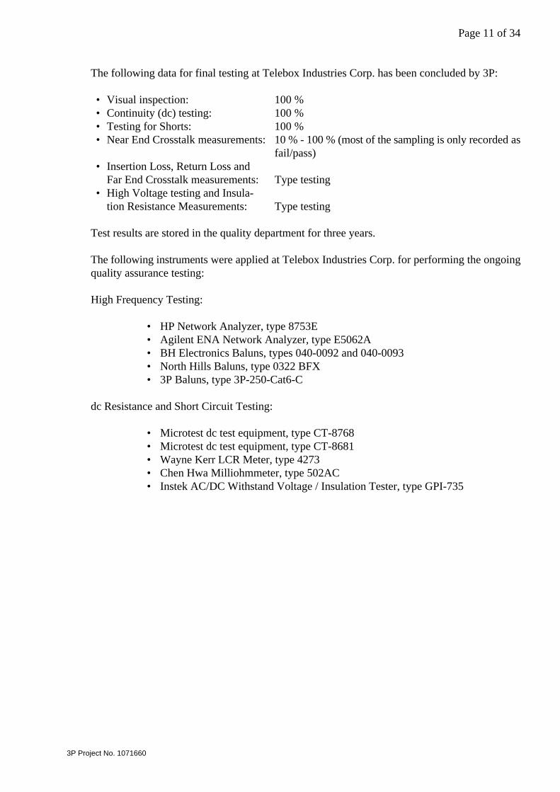
The following data for final testing at Telebox Industries Corp. has been concluded by 3P:
• Visual inspection: 100 %• Continuity (dc) testing: 100 %• Testing for Shorts: 100 %• Near End Crosstalk measurements: 10 % - 100 % (most of the sampling is only recorded as
fail/pass)• Insertion Loss, Return Loss and
Far End Crosstalk measurements: Type testing• High Voltage testing and Insula-
tion Resistance Measurements: Type testing
Test results are stored in the quality department for three years.
The following instruments were applied at Telebox Industries Corp. for performing the ongoingquality assurance testing:
High Frequency Testing:
• HP Network Analyzer, type 8753E• Agilent ENA Network Analyzer, type E5062A• BH Electronics Baluns, types 040-0092 and 040-0093• North Hills Baluns, type 0322 BFX• 3P Baluns, type 3P-250-Cat6-C
dc Resistance and Short Circuit Testing:
• Microtest dc test equipment, type CT-8768• Microtest dc test equipment, type CT-8681• Wayne Kerr LCR Meter, type 4273• Chen Hwa Milliohmmeter, type 502AC• Instek AC/DC Withstand Voltage / Insulation Tester, type GPI-735
Page 12 of 34
3P Project No. 1071660
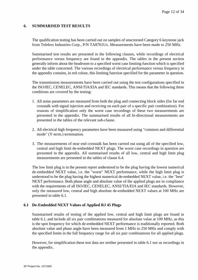
6. SUMMARISED TEST RESULTS
The qualification testing has been carried out on samples of unscreened Category 6 keystone jackfrom Telebox Industries Corp., P/N TA8761Ux. Measurements have been made to 250 MHz.
Summarised test results are presented in the following clauses, while recordings of electricalperformance versus frequency are found in the appendix. The tables in the present sectiongenerally inform about the headroom to a specified worst case limiting function which is specifiedunder the table concerned. The various recordings of electrical performance versus frequency inthe appendix contains, in red colour, this limiting function specified for the parameter in question.
The transmission measurements have been carried out using the test configurations specified inthe ISO/IEC, CENELEC, ANSI/TIA/EIA and IEC standards. This means that the following threeconditions are covered by the testing:
1. All noise parameters are measured from both the plug and connecting block sides (for far endcrosstalk with signal injection and receiving on each pair of a specific pair combination). Forreasons of simplification only the worst case recordings of these two measurements arepresented in the appendix. The summarised results of all bi-directional measurements arepresented in the tables of the relevant sub-clause.
2. All electrical high frequency parameters have been measured using "common and differentialmode" (Y-term.) termination.
3. The measurements of near end crosstalk has been carried out using all of the specified low,central and high limit de-embedded NEXT plugs. The worst case recordings in question arepresented in the appendix. All summarised results of all low, central and high limit plugmeasurements are presented in the tables of clause 6.4.
The low limit plug is in the present report understood to be the plug having the lowest numericalde-embedded NEXT value, i.e. the "worst" NEXT performance, while the high limit plug isunderstood to be the plug having the highest numerical de-embedded NEXT value, i.e. the "best"NEXT performance. Both phase angle and absolute value of the applied plugs are in compliancewith the requirements of all ISO/IEC, CENELEC, ANSI/TIA/EIA and IEC standards. However,only the measured low, central and high absolute de-embedded NEXT values at 100 MHz arepresented in table 6.1.
6.1 De-Embedded NEXT Values of Applied RJ 45 Plugs
Summarised results of testing of the applied low, central and high limit plugs are found intable 6.1, and include all six pair combinations measured for absolute value at 100 MHz, as thisis the spot frequency for which de-embedded NEXT performance is traditionally reported. Bothabsolute value and phase angle have been measured from 1 MHz to 250 MHz and comply withthe specified limits in the full frequency range for all six pair combinations for all applied plugs.
However, for simplification these test data are neither presented in table 6.1 nor as recordings inthe appendix.
Page 13 of 34
3P Project No. 1071660
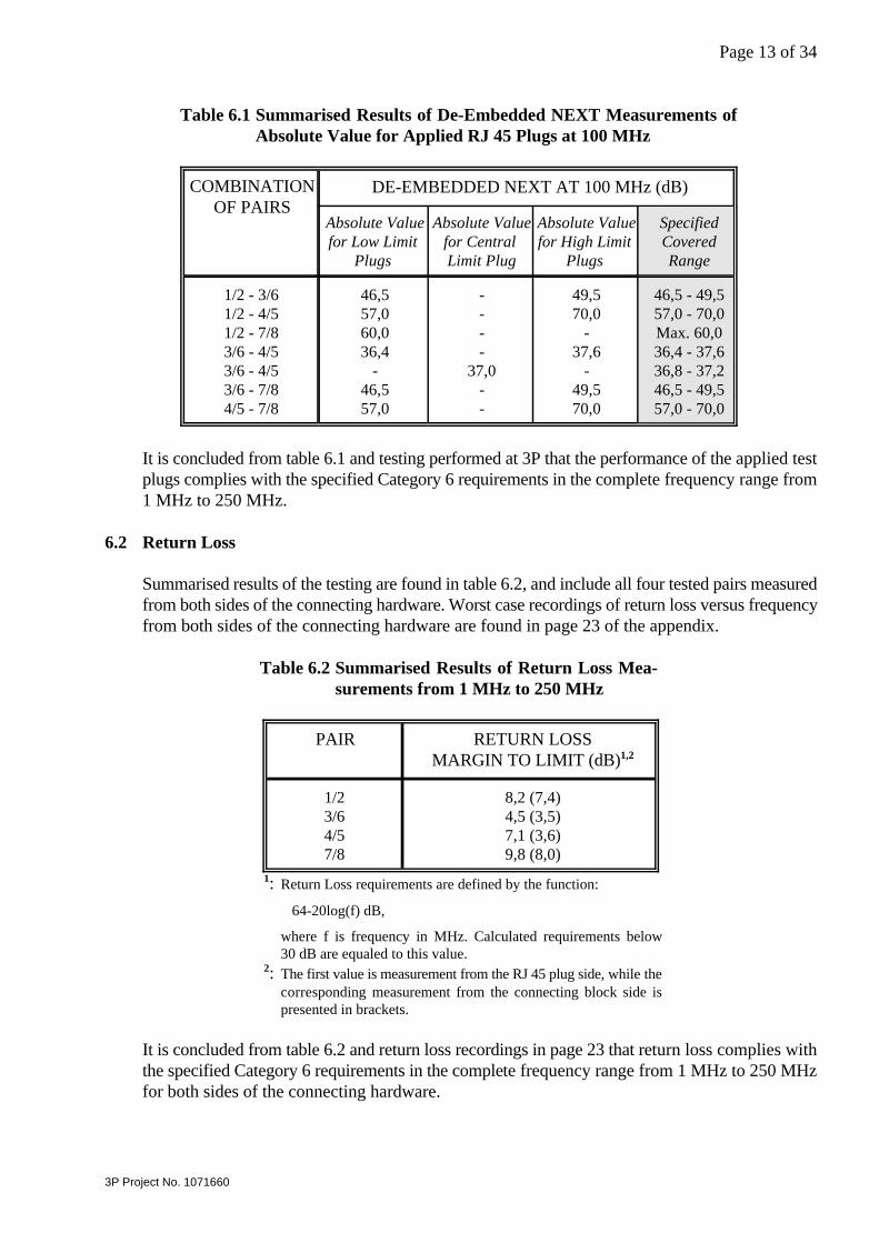
Table 6.1 Summarised Results of De-Embedded NEXT Measurements ofAbsolute Value for Applied RJ 45 Plugs at 100 MHz
COMBINATIONOF PAIRS
DE-EMBEDDED NEXT AT 100 MHz (dB)
Absolute Valuefor Low Limit
Plugs
Absolute Valuefor CentralLimit Plug
Absolute Valuefor High Limit
Plugs
SpecifiedCoveredRange
1/2 - 3/61/2 - 4/51/2 - 7/83/6 - 4/53/6 - 4/53/6 - 7/84/5 - 7/8
46,557,060,036,4
-46,557,0
----
37,0--
49,570,0
-37,6
-49,570,0
46,5 - 49,557,0 - 70,0Max. 60,036,4 - 37,636,8 - 37,246,5 - 49,557,0 - 70,0
It is concluded from table 6.1 and testing performed at 3P that the performance of the applied testplugs complies with the specified Category 6 requirements in the complete frequency range from1 MHz to 250 MHz.
6.2 Return Loss
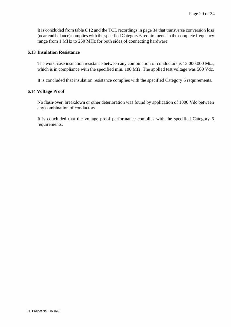
Summarised results of the testing are found in table 6.2, and include all four tested pairs measuredfrom both sides of the connecting hardware. Worst case recordings of return loss versus frequencyfrom both sides of the connecting hardware are found in page 23 of the appendix.
Table 6.2 Summarised Results of Return Loss Mea-surements from 1 MHz to 250 MHz
PAIR RETURN LOSSMARGIN TO LIMIT (dB)1,2
1/23/64/57/8
8,2 (7,4)4,5 (3,5)7,1 (3,6)9,8 (8,0)
: Return Loss requirements are defined by the function:1
64-20log(f) dB,
where f is frequency in MHz. Calculated requirements below30 dB are equaled to this value.
: The first value is measurement from the RJ 45 plug side, while the2
corresponding measurement from the connecting block side ispresented in brackets.
It is concluded from table 6.2 and return loss recordings in page 23 that return loss complies withthe specified Category 6 requirements in the complete frequency range from 1 MHz to 250 MHzfor both sides of the connecting hardware.
Page 14 of 34
3P Project No. 1071660
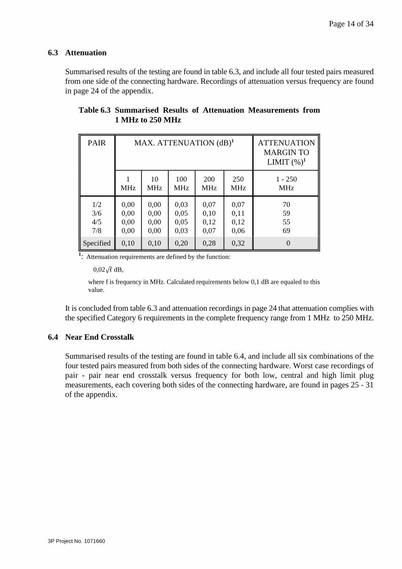
6.3 Attenuation
Summarised results of the testing are found in table 6.3, and include all four tested pairs measuredfrom one side of the connecting hardware. Recordings of attenuation versus frequency are foundin page 24 of the appendix.
Table 6.3 Summarised Results of Attenuation Measurements from1 MHz to 250 MHz
PAIR MAX. ATTENUATION (dB)1 ATTENUATIONMARGIN TOLIMIT (%)1
1MHz
10MHz
100MHz
200MHz
250MHz
1 - 250MHz
1/23/64/57/8
0,000,000,000,00
0,000,000,000,00
0,030,050,050,03
0,070,100,120,07
0,070,110,120,06
70595569
Specified 0,10 0,10 0,20 0,28 0,32 0
: Attenuation requirements are defined by the function: 1
0,02 dB,
where f is frequency in MHz. Calculated requirements below 0,1 dB are equaled to thisvalue.
It is concluded from table 6.3 and attenuation recordings in page 24 that attenuation complies withthe specified Category 6 requirements in the complete frequency range from 1 MHz to 250 MHz.
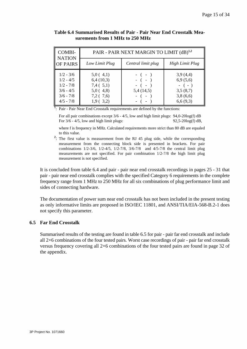
6.4 Near End Crosstalk
Summarised results of the testing are found in table 6.4, and include all six combinations of thefour tested pairs measured from both sides of the connecting hardware. Worst case recordings ofpair - pair near end crosstalk versus frequency for both low, central and high limit plugmeasurements, each covering both sides of the connecting hardware, are found in pages 25 - 31of the appendix.
Page 15 of 34
3P Project No. 1071660
Table 6.4 Summarised Results of Pair - Pair Near End Crosstalk Mea-surements from 1 MHz to 250 MHz
COMBI-NATION
OF PAIRS
PAIR - PAIR NEXT MARGIN TO LIMIT (dB)1,2
Low Limit Plug Central limit plug High Limit Plug
1/2 - 3/61/2 - 4/51/2 - 7/83/6 - 4/53/6 - 7/84/5 - 7/8
5,0 ( 4,1)6,4 (10,3)7,4 ( 5,1)5,0 ( 4,8)7,2 ( 7,6)1,9 ( 3,2)
- ( - ) - ( - ) - ( - )5,4 (14,5) - ( - ) - ( - )
3,9 (4,4)6,9 (5,6) - ( - )3,5 (8,7)3,8 (6,6)6,6 (9,3)
: Pair - Pair Near End Crosstalk requirements are defined by the functions:1
For all pair combinations except 3/6 - 4/5, low and high limit plugs: 94,0-20log(f) dBFor 3/6 - 4/5, low and high limit plugs: 92,5-20log(f) dB,
where f is frequency in MHz. Calculated requirements more strict than 80 dB are equaledto this value.
: The first value is measurement from the RJ 45 plug side, while the corresponding2
measurement from the connecting block side is presented in brackets. For paircombinations 1/2-3/6, 1/2-4/5, 1/2-7/8, 3/6-7/8 and 4/5-7/8 the central limit plugmeasurements are not specified. For pair combination 1/2-7/8 the high limit plugmeasurement is not specified.
It is concluded from table 6.4 and pair - pair near end crosstalk recordings in pages 25 - 31 thatpair - pair near end crosstalk complies with the specified Category 6 requirements in the completefrequency range from 1 MHz to 250 MHz for all six combinations of plug performance limit andsides of connecting hardware.
The documentation of power sum near end crosstalk has not been included in the present testingas only informative limits are proposed in ISO/IEC 11801, and ANSI/TIA/EIA-568-B.2-1 doesnot specify this parameter.
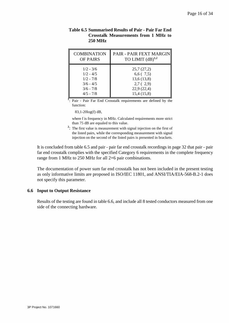
6.5 Far End Crosstalk
Summarised results of the testing are found in table 6.5 for pair - pair far end crosstalk and includeall 2×6 combinations of the four tested pairs. Worst case recordings of pair - pair far end crosstalkversus frequency covering all 2×6 combinations of the four tested pairs are found in page 32 ofthe appendix.
Page 16 of 34
3P Project No. 1071660
Table 6.5 Summarised Results of Pair - Pair Far EndCrosstalk Measurements from 1 MHz to250 MHz
COMBINATIONOF PAIRS
PAIR - PAIR FEXT MARGINTO LIMIT (dB)1,2
1/2 - 3/61/2 - 4/51/2 - 7/83/6 - 4/53/6 - 7/84/5 - 7/8
25,7 (27,2) 6,6 ( 7,5)13,6 (13,8) 2,7 ( 2,9)22,9 (22,4)15,4 (15,8)
: Pair - Pair Far End Crosstalk requirements are defined by the1
function:
83,1-20log(f) dB,
where f is frequency in MHz. Calculated requirements more strictthan 75 dB are equaled to this value.
: The first value is measurement with signal injection on the first of2
the listed pairs, while the corresponding measurement with signalinjection on the second of the listed pairs is presented in brackets.
It is concluded from table 6.5 and pair - pair far end crosstalk recordings in page 32 that pair - pairfar end crosstalk complies with the specified Category 6 requirements in the complete frequencyrange from 1 MHz to 250 MHz for all 2×6 pair combinations.
The documentation of power sum far end crosstalk has not been included in the present testingas only informative limits are proposed in ISO/IEC 11801, and ANSI/TIA/EIA-568-B.2-1 doesnot specify this parameter.
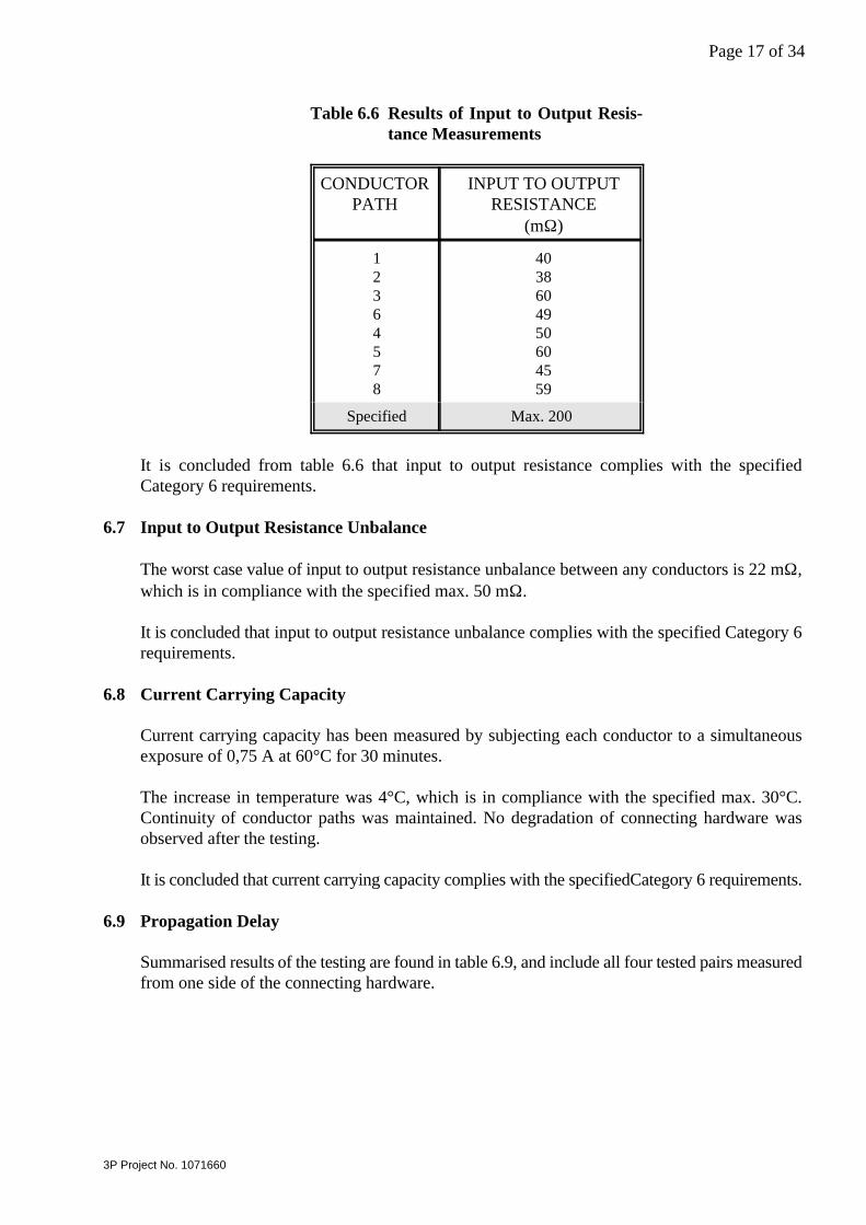
6.6 Input to Output Resistance
Results of the testing are found in table 6.6, and include all 8 tested conductors measured from oneside of the connecting hardware.
Page 17 of 34
3P Project No. 1071660
Table 6.6 Results of Input to Output Resis-tance Measurements
CONDUCTORPATH
INPUT TO OUTPUTRESISTANCE
(mΩ)
12364578
4038604950604559
Specified Max. 200
It is concluded from table 6.6 that input to output resistance complies with the specifiedCategory 6 requirements.
6.7 Input to Output Resistance Unbalance
The worst case value of input to output resistance unbalance between any conductors is 22 mΩ,which is in compliance with the specified max. 50 mΩ.
It is concluded that input to output resistance unbalance complies with the specified Category 6requirements.
6.8 Current Carrying Capacity
Current carrying capacity has been measured by subjecting each conductor to a simultaneousexposure of 0,75 A at 60°C for 30 minutes.
The increase in temperature was 4°C, which is in compliance with the specified max. 30°C.Continuity of conductor paths was maintained. No degradation of connecting hardware wasobserved after the testing.
It is concluded that current carrying capacity complies with the specifiedCategory 6 requirements.
6.9 Propagation Delay
Summarised results of the testing are found in table 6.9, and include all four tested pairs measuredfrom one side of the connecting hardware.

Page 18 of 34
3P Project No. 1071660
Table 6.9 Summarised Results of Propaga-tion Delay Measurements from1 MHz to 250 MHz
PAIR PROPAGATION DELAY(nsec)
1/23/64/57/8
Max. 0,6Max. 0,7Max. 0,8Max. 0,6
Specified Max. 2,5
It is concluded from table 6.9 that propagation delay complies with the specified Category 6requirements in the complete frequency range from 1 MHz to 250 MHz.
6.10 Delay Skew
Summarised results of the testing are found in table 6.10, and include all six combinations of thefour tested pairs measured from one side of the connecting hardware.
Table 6.10 Summarised Results of Delay SkewMeasurements from 1 MHz to250 MHz
COMBINATION OF PAIRS
DELAY SKEW (nsec)
1/2 - 3/61/2 - 4/51/2 - 7/83/6 - 4/53/6 - 7/84/5 - 7/8
Max. 0,06Max. 0,13Max. 0,02Max. 0,07Max. 0,08Max. 0,15
Specified Max. 1,25
It is concluded from table 6.10 that delay skew complies with the specified Category 6 require-ments in the complete frequency range from 1 MHz to 250 MHz.
6.11 Electromagnetic Performance
Summarised results of coupling attenuation measurements are found in table 6.11, and includeall four tested pairs recorded as both near and far end measurements. The connecting hardwareis connected with unscreened horizontal cable and RJ 45 plug terminated unscreened horizontalcable. Worst case recording of electromagnetic performance is found in page 33 of the appendix.

Page 19 of 34
3P Project No. 1071660
Table 6.11 Summarised Results of CouplingAttenuation Measurements
PAIR COUPLING ATTENUATIONMARGIN TO LIMIT (dB)1,2
1/23/64/57/8
16 (23)10 (12)21 (12)20 (18)
: Coupling attenuation requirements are defined by the1
functions:
35 dB between 30 MHz and 100 MHz 35-20log( ) dB between 100 MHz and 1 GHz,
where f is frequency in MHz.: The first value is measurement from near end, while the2
corresponding measurement from far end is presented inbrackets.
It is concluded from table 6.11 and coupling attenuation recordings in page 33 that couplingattenuation complies with the specified Category 6 requirements when recorded as both near andfar end measurement.
6.12 Balance Measured as Transverse Conversion Loss (TCL)
Summarised results of the testing are found in table 6.12 for balance measured as TCL, andinclude all four tested pairs measured from both sides of the connecting hardware. Worst caserecordings of TCL versus frequency from both sides of the connecting hardware are found inpage 34 of the appendix.
Table 6.12 Summarised Results of Balance(TCL) Measurements from 1 MHzto 250 MHz
PAIR BALANCE (TCL) MARGINTO LIMIT (dB)1,2
1/23/64/57/8
10,4 (15,1) 6,4 ( 5,9)15,6 (13,4)16,5 (16,1)
: Requirements to Balance, measured as TCL, are defined1
by the function:
68 - 20log(f) dB,
where f is frequency in MHz. Calculated requirementsmore strict than 60 dB are equaled to this value.
: The first value is measurement from the RJ 45 plug side,2
while the corresponding measurement from theconnecting block side is presented in brackets.
Page 20 of 34
3P Project No. 1071660
It is concluded from table 6.12 and the TCL recordings in page 34 that transverse conversion loss(near end balance) complies with the specified Category 6 requirements in the complete frequencyrange from 1 MHz to 250 MHz for both sides of connecting hardware.
6.13 Insulation Resistance
The worst case insulation resistance between any combination of conductors is 12.000.000 MΩ,which is in compliance with the specified min. 100 MΩ. The applied test voltage was 500 Vdc.
It is concluded that insulation resistance complies with the specified Category 6 requirements.
6.14 Voltage Proof
No flash-over, breakdown or other deterioration was found by application of 1000 Vdc betweenany combination of conductors.
It is concluded that the voltage proof performance complies with the specified Category 6requirements.

Page 21 of 34
3P Project No. 1071660
7. CONCLUSION
Samples of unscreened Category 6 keystone jack from Telebox Industries Corp. have beensubjected to qualification testing according to 3P requirements for Unscreened Category 6ISO/IEC, EN & TIA/EIA Connecting Hardware.
The transmission performance of the unscreened Category 6 keystone jack from TeleboxIndustries Corp., P/N TA8761Ux having PC board marking 001-87604 C6 A01 1F00, does inevery respect comply with the requirements of the following international standards:
• ISO/IEC 2 Edition 11801, Cat. 6nd
• CENELEC EN 50173-1, Cat. 6• ANSI/TIA/EIA-568-B.2-1, Cat. 6• IEC 60603-7-4, Cat. 6
The positive conclusion of the testing covers all unscreened products from the qualifiedproduction line of Telebox Industries Corp. having identical PCB circuitry. Presently this onlyincludes Telebox Industries Corp. keystone jack,
• P/N TA8761Ux
The company
Telebox Industries Corp.4F, No. 306, Tatung Road, Sec. 1Hsichih-Taipei 221TaiwanR.O.C.
is qualified at their Hsichih site to produce the connecting hardware in question with a 3P ratingas Unscreened Category 6 ISO/IEC, EN & TIA/EIA Connecting Hardware.
The qualification will be valid until failure to pass one of the maintenance of qualification testprogrammes, which will be performed at 12 months intervals.
The present testing does not include the reliability test programmes specified in ISO/IEC,CENELEC, ANSI/TIA/EIA and IEC standards. Only the transmission performance is covered bythe 3P testing. It is assumed that the reliability of the applied RJ 45 jacks is adequate to securesafe interconnection to the patch cords throughout a lifetime of normal application of theconnecting hardware.

Page 22 of 34
3P Project No. 1071660
8. APPENDIX: Data Sheets of Transmission Performance versus Frequency
All characteristic and most critical recordings of transmission performance are presented in thefollowing way:
Page 23 Worst case recordings of return loss for all four pairs between 1 MHz and250 MHz.
Page 24 Recordings of attenuation for all four pairs between 1 MHz and 250 MHz.
Pages 25 - 31 Worst case recordings of pair - pair near end crosstalk for all six combinations ofpairs between 1 MHz and 250 MHz. Each page includes recordings of one specificpair combination measured using low and, if applicable, high limit plugs. For paircombination 3/6 - 4/5 the worst case central limit plug recording is presented ina separate page due to the different mated pair performance limits specified forlow/high and central limit plugs.
Page 32 Worst case recordings of pair - pair far end crosstalk for all 2×6 combinations ofpairs between 1 MHz and 250 MHz.
Page 33 Worst case recording of electromagnetic performance between 30 MHz and1 GHz.
Page 34 Worst case recordings of balance measured as TCL for all four pairs between1 MHz and 250 MHz.
Date: 2007.09.07
Page 23 of 341 MHz
Pair 1/2:Worst case is measurement fromconnecting block side.
Pair 3/6:Worst case is measurement fromconnecting block side.
Pair 4/5:Worst case is measurement fromconnecting block side.
Pair 7/8:Worst case is measurement fromconnecting block side.
Limiting function:Category 6 limit:
The worst case of Return Loss for allfour pairs complies with the speci-fied Category 6 limit in the completefrequency range from 1 MHz to250 MHz.
3P Project No. 1071660
0 dB
100 dB1 GHz
20
40
60
80
Worst case recordings of ReturnLoss for all four pairs from 1 MHzto 250 MHz.
10 100

Date: 2007.09.19
Page 24 of 341 MHz
Pair 1/2:Pair 3/6:Pair 4/5:Pair 7/8:
Limiting function:Category 6 limit:
The Attenuation for all four pairscomplies with the specified Catego-ry 6 limit in the complete frequencyrange from 1 MHz to 250 MHz.
3P Project No. 1071660
0 dB
0,5 dB1 GHz
0,1
0,2
0,3
0,4
Recordings of Attenuation for allfour pairs from 1 MHz to250 MHz.
10 100

Date: 2007.09.07
Page 25 of 341 MHz
Low limit plug [46,5 dB]:Worst case is measurement fromconnecting block side.
High limit plug [49,5 dB]:Worst case is measurement fromplug side.
Limiting function:Category 6 limit:
The worst case of Near End Cross-talk for pair combination 1/2 – 3/6measured with both low and highlimit plugs complies with the speci-fied Category 6 limit in the completefrequency range from 1 MHz to250 MHz.
3P Project No. 1071660
0 dB
100 dB1 GHz
20
40
60
80
Worst case recordings of Near EndCrosstalk for pair combination1/2 - 3/6 measured with low andhigh limit plugs from 1 MHz to250 MHz.
10 100

Date: 2007.09.07
Page 26 of 341 MHz
Low limit plug [57,0 dB]:Worst case is measurement fromplug side.
High limit plug [70,0 dB]:Worst case is measurement fromconnecting block side.
Limiting function:Category 6 limit:
The worst case of Near End Cross-talk for pair combination 1/2 – 4/5measured with both low and highlimit plugs complies with the spe-cified Category 6 limit in the com-plete frequency range from 1 MHz to250 MHz.
3P Project No. 1071660
0 dB
100 dB1 GHz
20
40
60
80
Worst case recordings of Near EndCrosstalk for pair combination1/2 - 4/5 measured with low andhigh limit plugs from 1 MHz to250 MHz.
10 100

Date: 2007.09.07
Page 27 of 341 MHz
Low limit plug [60,0 dB]:Worst case is measurement fromconnecting block side.
Limiting function:Category 6 limit:
The worst case of Near End Cross-talk for pair combination 1/2 – 7/8measured with low limit plug com-plies with the specified Category 6limit in the complete frequency rangefrom 1 MHz to 250 MHz.
3P Project No. 1071660
0 dB
100 dB1 GHz
20
40
60
80
Worst case recording of Near EndCrosstalk for pair combination1/2 - 7/8 measured with low limitplug from 1 MHz to 250 MHz.
10 100

Date: 2007.09.07
Page 28 of 341 MHz
Low limit plug [36,4 dB]:Worst case is measurement fromconnecting block side.
High limit plug [37,6 dB]:Worst case is measurement fromplug side.
Limiting function:Category 6 limit:
The worst case of Near End Cross-talk for pair combination 3/6 – 4/5measured with both low and highlimit plugs complies with the specifi-ed Category 6 limit in the completefrequency range from 1 MHz to250 MHz.
3P Project No. 1071660
0 dB
100 dB1 GHz
20
40
60
80
Worst case recordings of Near EndCrosstalk for pair combination3/6 - 4/5 measured with low andhigh limit plugs from 1 MHz to250 MHz.
10 100
Date: 2007.09.07
Page 29 of 341 MHz
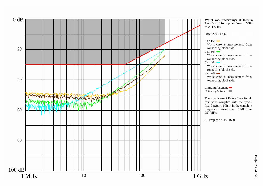
Central limit plug [37,0 dB]:Worst case is measurement fromplug side.
Limiting function:Category 6 limit:
The worst case of Near End Cross-talk for pair combination 3/6 – 4/5measured with central limit plugcomplies with the specified Catego-ry 6 limit in the complete frequencyrange from 1 MHz to 250 MHz.
3P Project No. 1071660
0 dB
100 dB1 GHz
20
40
60
80
Worst case recording of Near EndCrosstalk for pair combination3/6 - 4/5 measured with centrallimit plug from 1 MHz to 250 MHz.
10 100
Date: 2007.09.07
Page 30 of 341 MHz
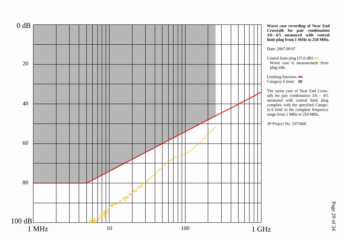
Low limit plug [46,5 dB]:Worst case is measurement fromplug side.
High limit plug [49,5 dB]:Worst case is measurement fromplug side.
Limiting function:Category 6 limit:
The worst case of Near End Cross-talk for pair combination 3/6 – 7/8measured with both low and highlimit plugs complies with the specifi-ed Category 6 limit in the completefrequency range from 1 MHz to250 MHz.
3P Project No. 1071660
0 dB
100 dB1 GHz
20
40
60
80
Worst case recordings of Near EndCrosstalk for pair combination3/6 - 7/8 measured with low andhigh limit plugs from 1 MHz to250 MHz.
10 100
Date: 2007.09.07
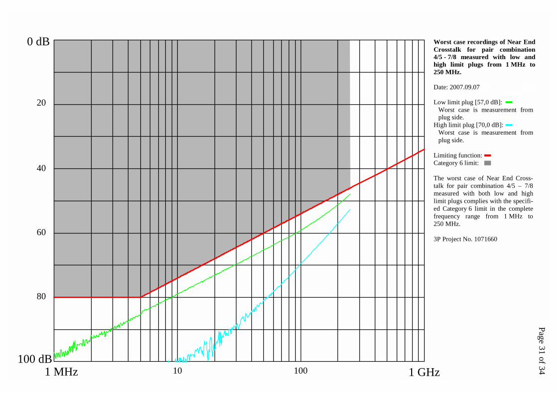
Page 31 of 341 MHz
Low limit plug [57,0 dB]:Worst case is measurement fromplug side.
High limit plug [70,0 dB]:Worst case is measurement fromplug side.
Limiting function:Category 6 limit:
The worst case of Near End Cross-talk for pair combination 4/5 – 7/8measured with both low and highlimit plugs complies with the specifi-ed Category 6 limit in the completefrequency range from 1 MHz to250 MHz.
3P Project No. 1071660
0 dB
100 dB1 GHz
20
40
60
80
Worst case recordings of Near EndCrosstalk for pair combination4/5 - 7/8 measured with low andhigh limit plugs from 1 MHz to250 MHz.
10 100

Date: 2007.09.18
Page 32 of 341 MHz
Pair combination 1/2 – 3/6:Worst case is signal injection onpair 1/2.
Pair combination 1/2 – 4/5:Worst case is signal injection onpair 1/2.
Pair combination 1/2 – 7/8:Worst case is signal injection onpair 1/2.
Pair combination 3/6 – 4/5:Worst case is signal injection onpair 3/6.
Pair combination 3/6 – 7/8:Worst case is signal injection onpair 7/8.
Pair combination 4/5 – 7/8:Worst case is signal injection onpair 4/5.
Limiting function:Category 6 limit:
The worst case of Far End Crosstalkfor all six pair combinations com-plies with the specified Category 6limit in the complete frequency rangefrom 1 MHz to 250 MHz.
3P Project No. 1071660
0 dB
100 dB1 GHz
20
40
60
80
Worst case recordings of Far EndCrosstalk for all six pair combina-tions from 1 MHz to 250 MHz.
10 100

Page 33 of 341 MHz
Measured on connecting hardwareassembled unscreened cables andtested in aerial span. The cablesalone were having EMC performan-ce of 63 dB.
Date: 2007.10.08
EMC Performance: 45 dB
The EMC Performance is derivedfrom the interception of a limitingfunction with the worst case Coup-ling Attenuation value at any fre-quency for any pair. The constantvalue from 30 MHz to 100 MHz isdefined as the EMC performance.
3P Project No. 1071660
0 dB
100 dB1 GHz
20
40
60
80
Worst case recording of EMC Per-formance from 30 MHz to 1 GHz.The measurement is based on re-cordings of Coupling Attenuationfor all four pairs of the connectinghardware.
200 400 600 800

Date: 2007.10.09
Page 34 of 341 MHz
Pair 1/2:Worst case is measurement fromplug side.
Pair 3/6:Worst case is measurement fromconnecting block side.
Pair 4/5:Worst case is measurement fromconnecting block side.
Pair 7/8:Worst case is measurement fromconnecting block side.
Limiting function:Category 6 limit:
The worst case of Transverse Con-version Loss for all four pairs com-plies with the specified Category 6limit in the complete frequency rangefrom 1 MHz to 250 MHz.
3P Project No. 1071660
0 dB
100 dB1 GHz
20
40
60
80
Worst case recordings of Trans-verse Conversion Loss (TCL) forall four pairs from 1 MHz to250 MHz.
10 100