Embed Size (px)
DESCRIPTION
ndt
Citation preview
BIT INSPECTION TECHNOLOGY NDT,WELDING & THIRD PARTY INSPECTION AN ISO 9001 – 2008 CERTIFIED ORGANISATION
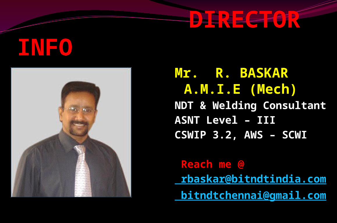
DIRECTOR INFOMr. R. BASKAR A.M.I.E (Mech)
NDT & Welding Consultant
ASNT Level – IIICSWIP 3.2, AWS – SCWI
Reach me @ [email protected] [email protected]
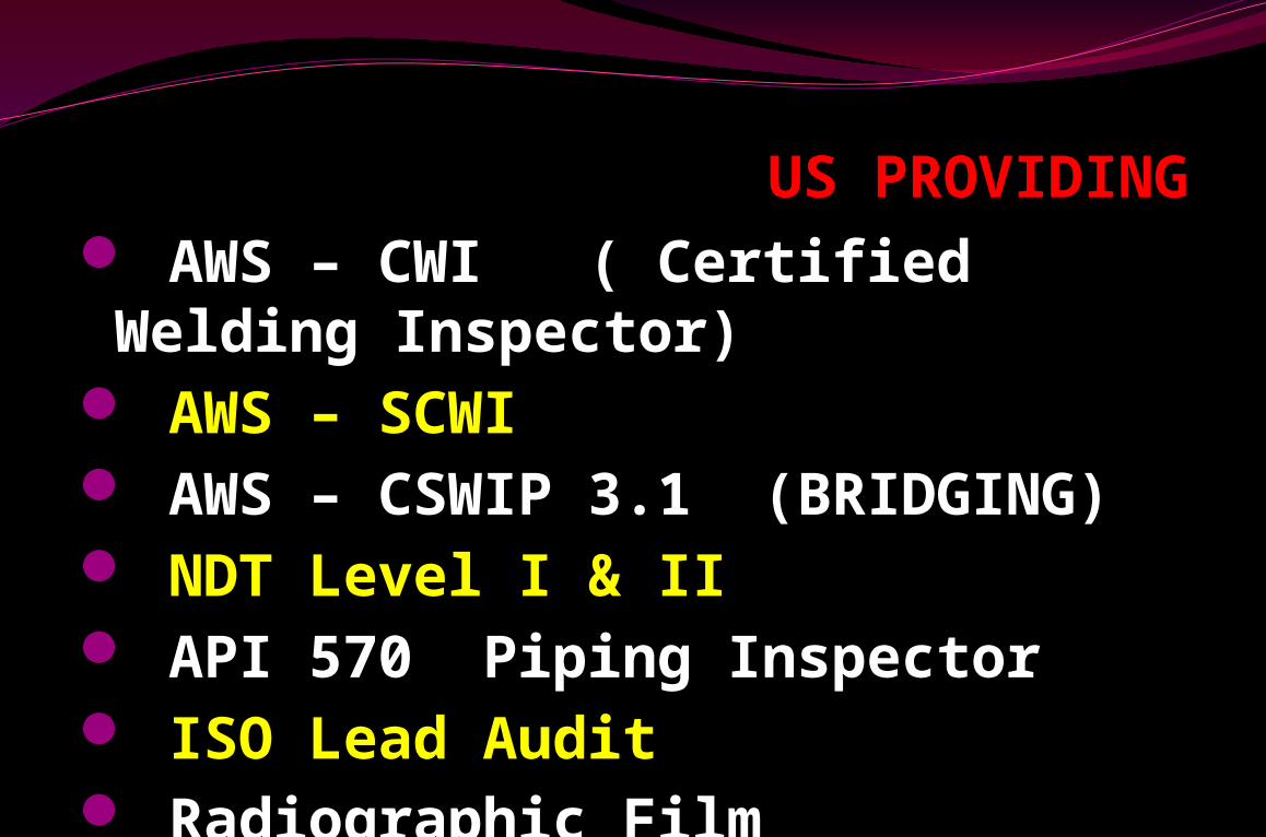
US PROVIDING AWS – CWI ( Certified Welding Inspector)
AWS – SCWI AWS – CSWIP 3.1 (BRIDGING) NDT Level I & II API 570 Piping Inspector ISO Lead Audit Radiographic Film Interpretation (RTFI)
INVITING ALL B.E., (Mech,Meta,Elec,Auto, Prod) Diploma (Mech,Meta,Elec,Auto, Prod) ITI B.Sc.,/M.Sc., ( Physics, Chemistry,
Material science) Welders Welding supervisors
Potential Opportunities inOil & Gas Sectors in
Gulf Canada India Australia And World wide
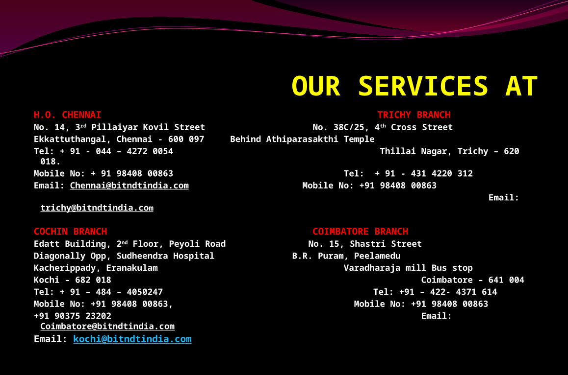
OUR SERVICES ATH.O. CHENNAI TRICHY BRANCHNo. 14, 3rd Pillaiyar Kovil Street No. 38C/25, 4th Cross StreetEkkattuthangal, Chennai - 600 097 Behind Athiparasakthi Temple Tel: + 91 - 044 – 4272 0054 Thillai Nagar, Trichy – 620 018. Mobile No: + 91 98408 00863 Tel: + 91 - 431 4220 312Email: [email protected] Mobile No: +91 98408 00863 Email: [email protected]
COCHIN BRANCH COIMBATORE BRANCHEdatt Building, 2nd Floor, Peyoli Road No. 15, Shastri StreetDiagonally Opp, Sudheendra Hospital B.R. Puram, PeelameduKacherippady, Eranakulam Varadharaja mill Bus stopKochi – 682 018 Coimbatore – 641 004Tel: + 91 – 484 – 4050247 Tel: +91 – 422- 4371 614Mobile No: +91 98408 00863, Mobile No: +91 98408 00863+91 90375 23202 Email:
Email: [email protected]
FOR MORE INFO @
www.bitndtindia.com
Non - Destructive Examination (NDE)

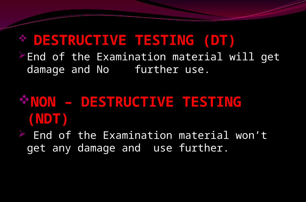
DESTRUCTIVE TESTING (DT)End of the Examination material will get
damage and No further use.
NON – DESTRUCTIVE TESTING (NDT)
End of the Examination material won’t get any damage and use further.
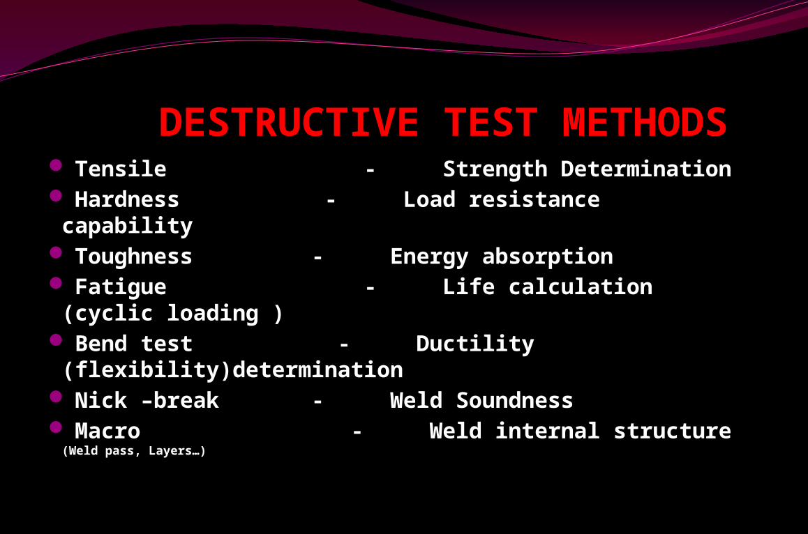
DESTRUCTIVE TEST METHODS Tensile - Strength Determination Hardness - Load resistance capability Toughness - Energy absorption Fatigue - Life calculation (cyclic loading )
Bend test - Ductility (flexibility)determination
Nick –break - Weld Soundness Macro - Weld internal structure (Weld
pass, Layers…)
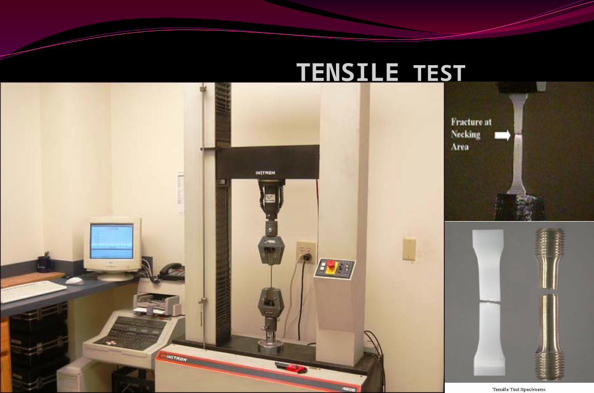
TENSILE TEST
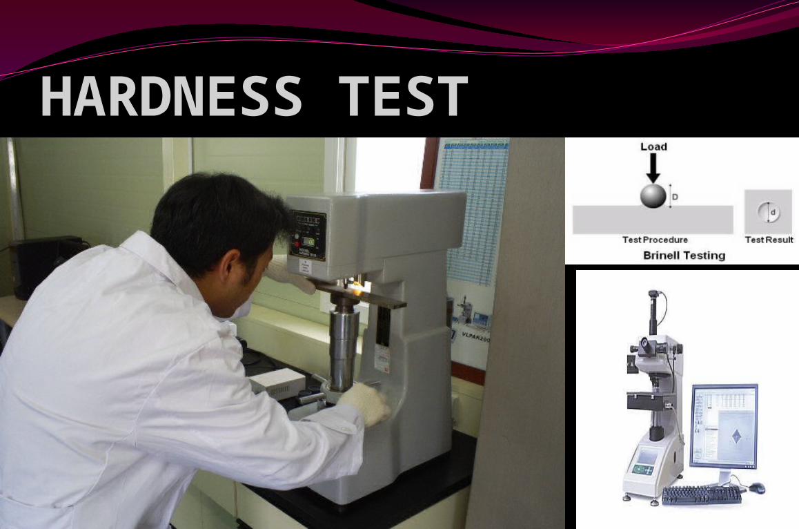
HARDNESS TEST
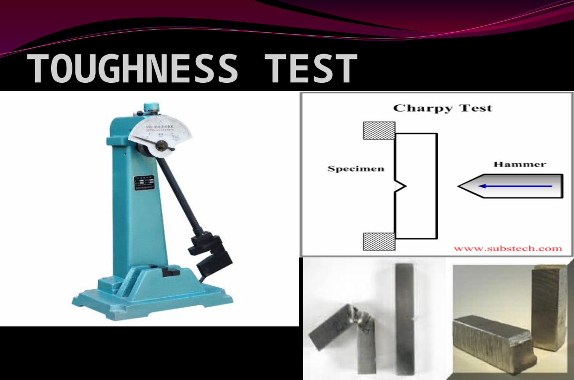
TOUGHNESS TEST
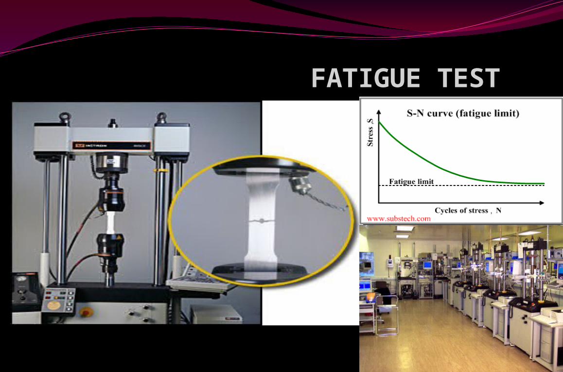
FATIGUE TEST
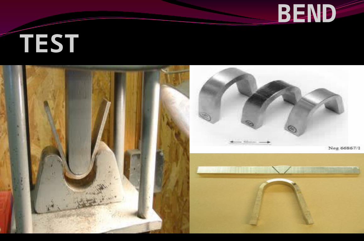
BEND TEST
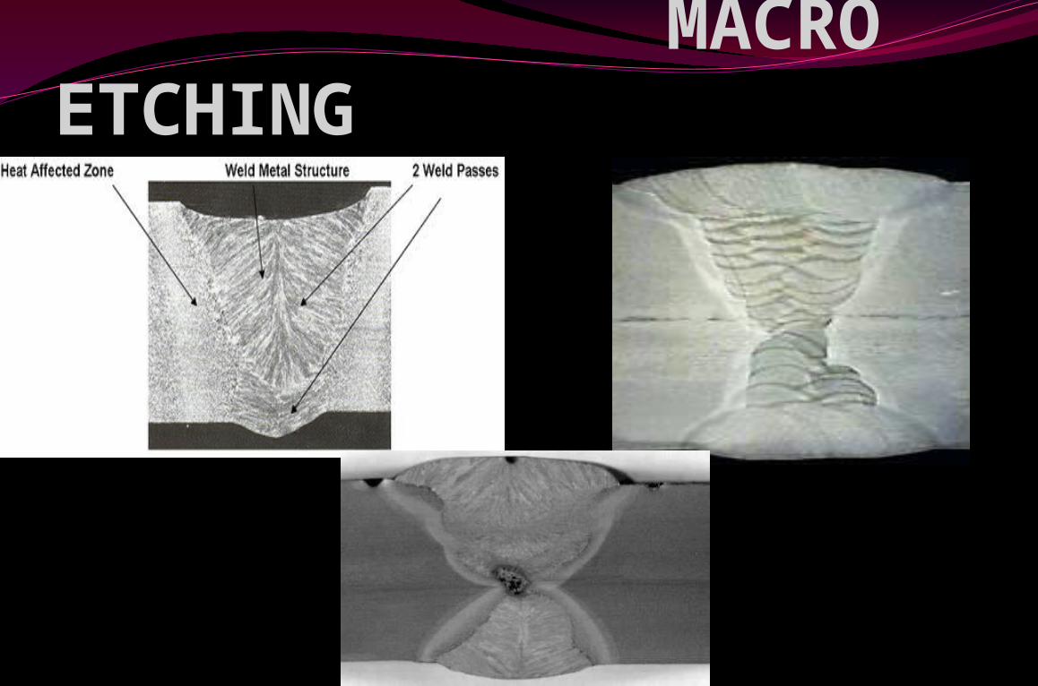
MACRO ETCHING
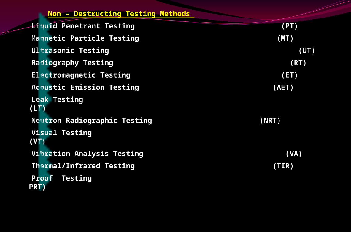
Non - Destructing Testing Methods
Liquid Penetrant Testing (PT)
Magnetic Particle Testing (MT)
Ultrasonic Testing (UT)
Radiography Testing (RT)
Electromagnetic Testing (ET)
Acoustic Emission Testing (AET)
Leak Testing (LT)
Neutron Radiographic Testing (NRT)
Visual Testing (VT)
Vibration Analysis Testing (VA)
Thermal/Infrared Testing (TIR)
Proof Testing PRT)
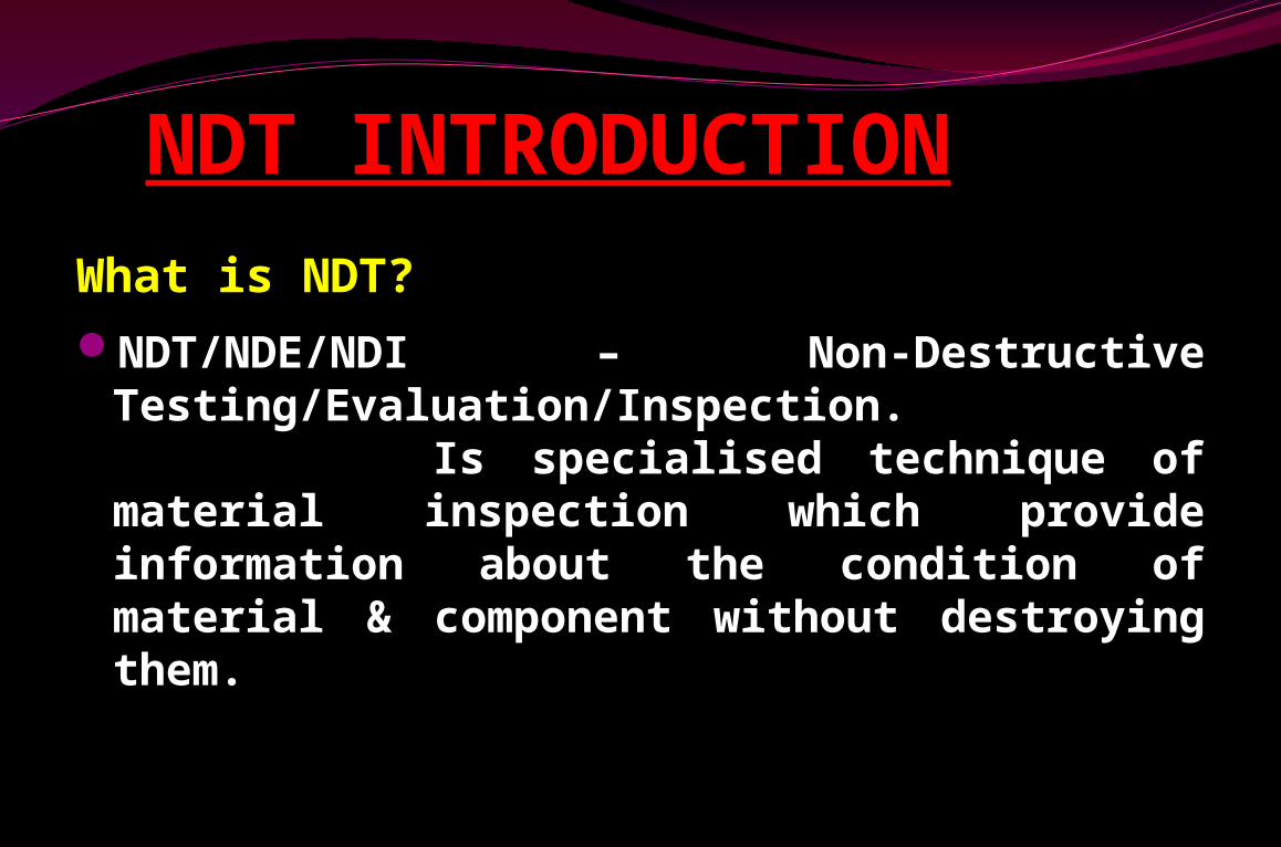
NDT INTRODUCTIONWhat is NDT?NDT/NDE/NDI – Non-Destructive
Testing/Evaluation/Inspection. Is specialised technique of material inspection which provide information about the condition of material & component without destroying them.
NDT is one of the Quality control (QC) tool of various industries, such as,
AircraftAutomotiveOil & Gas industryConstruction (welding & fabrication)Casting & forgingManufacturing (Pressure vessel/Valve)Petrochemical RefineryShip buildingPipelinePower generation & Nuclear
Why NDT? To ensure product reliability
To prevent accidents , save human life & avoid failure
To make a profit for user To ensure customer satisfaction & to maintain
the manufactures good name To control manufacturing costs To lower manufacturing costs To maintain a uniform quality level Do not change any properties of material
Uses of NDTFlaw Detection (Depth, length & width) and
EvaluationLeak Detection & Location Determination
• Dimensional & Coating thickness Measurements Structure and Microstructure Characterization Estimation of Mechanical and Physical Properties Stress (Strain) and Dynamic Response
Measurements Material Sorting (conductivity)and Chemical
Composition DeterminationThickness & Hardness MeasurementsHeat treatments condition & Corrosion thinning
INDUSTRIAL APPLICATIONS NDTCan be applied to all levels of material usage
Raw materialsFabricationFinishingIn-ServiceOverhaul
Common Application of NDT
Inspection of Raw Products
Inspection Following Secondary Processing
In-Services Damage Inspection

Inspection of Raw Products
Forgings Castings Extrusions

Machining Welding Grinding Heat treating Plating
Inspection Following Secondary Processing
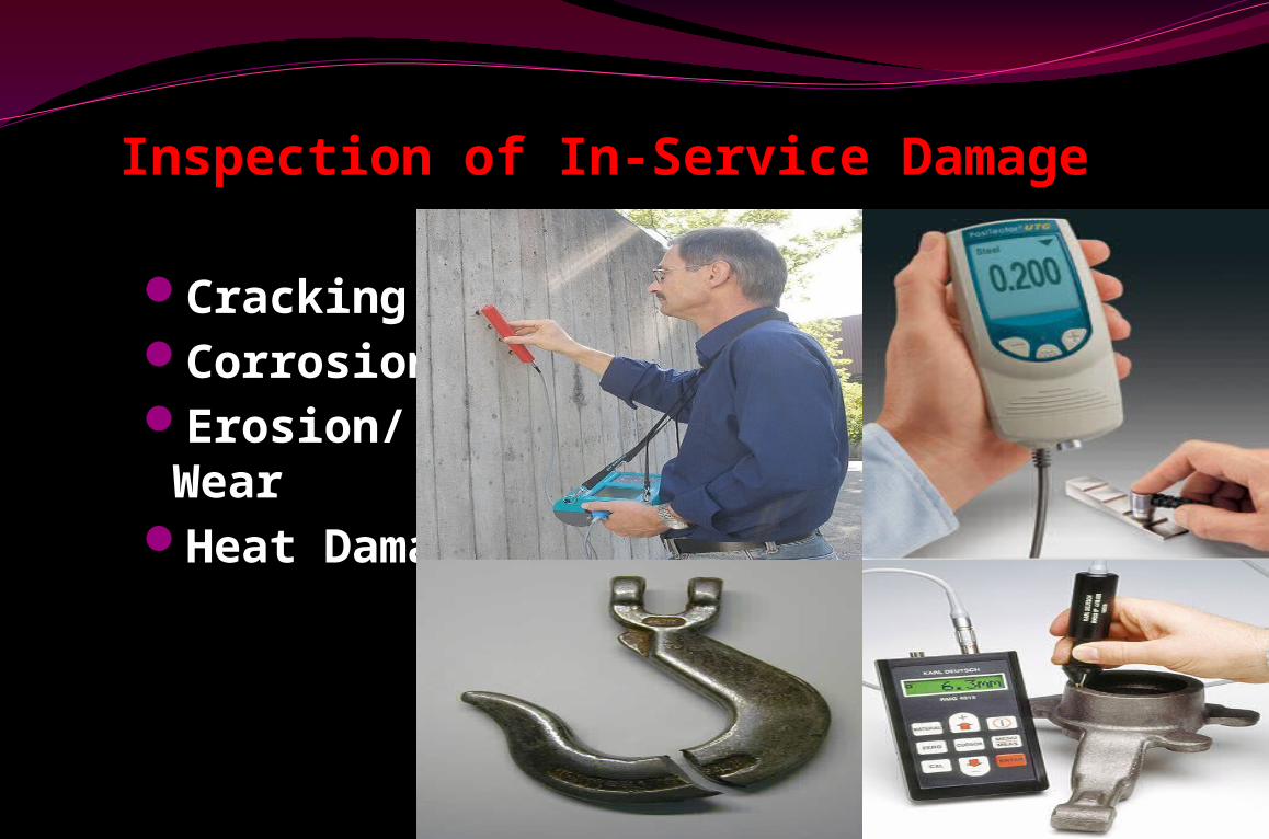
CrackingCorrosionErosion/WearHeat Damage
Inspection of In-Service Damage
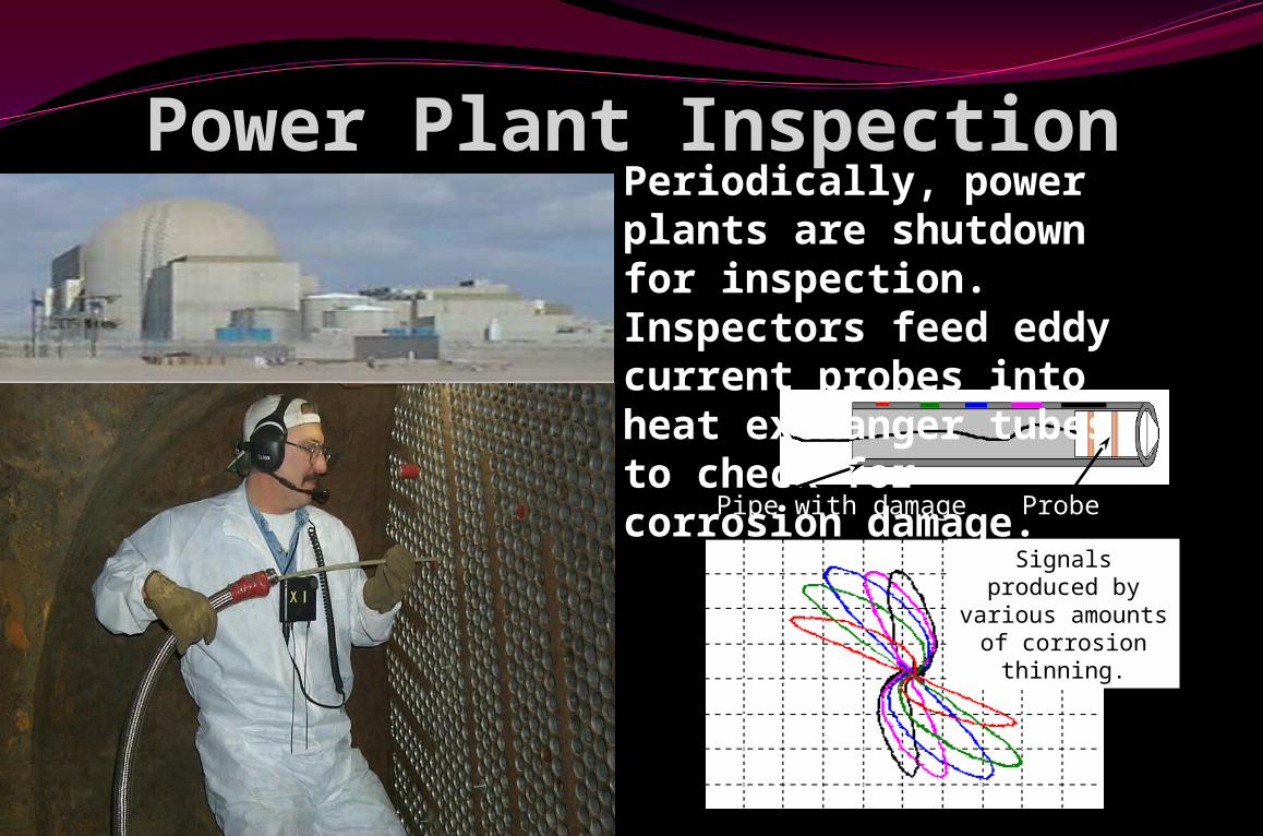
Power Plant Inspection
Probe
Signals produced by various amounts of corrosion thinning.
Periodically, power plants are shutdown for inspection. Inspectors feed eddy current probes into heat exchanger tubes to check for corrosion damage.Pipe with damage
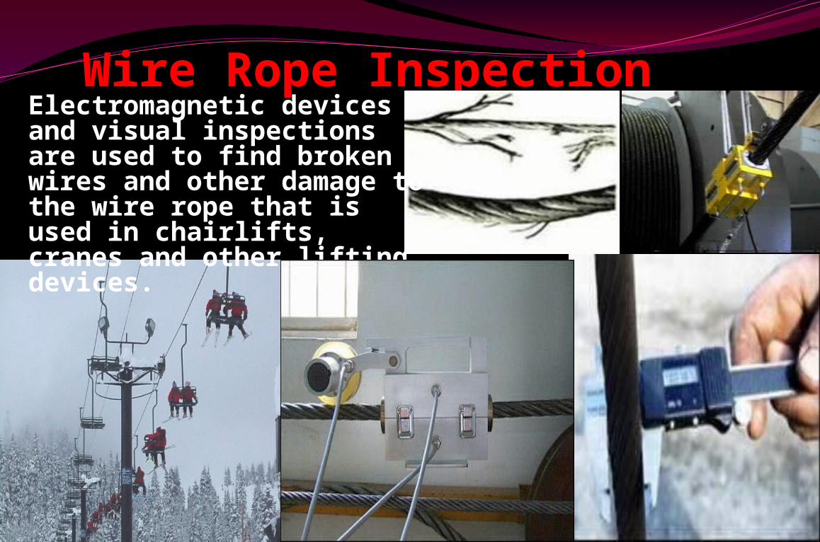
Wire Rope InspectionElectromagnetic devices and visual inspections are used to find broken wires and other damage to the wire rope that is used in chairlifts, cranes and other lifting devices.
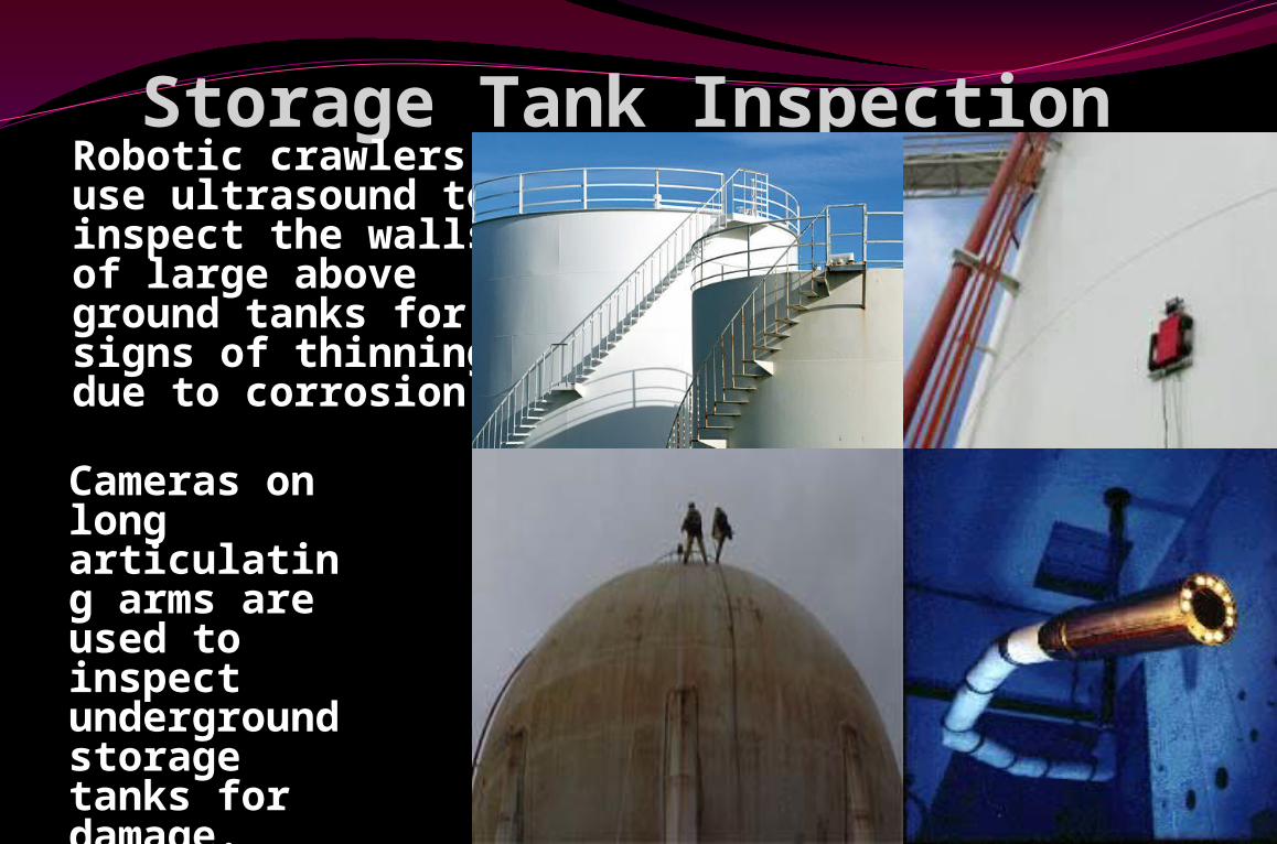
Storage Tank InspectionRobotic crawlers use ultrasound to inspect the walls of large above ground tanks for signs of thinning due to corrosion.
Cameras on long articulating arms are used to inspect underground storage tanks for damage.
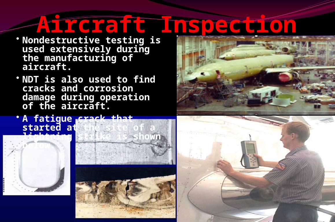
Aircraft Inspection• Nondestructive testing is used extensively during the manufacturing of aircraft.
• NDT is also used to find cracks and corrosion damage during operation of the aircraft.
• A fatigue crack that started at the site of a lightning strike is shown below.
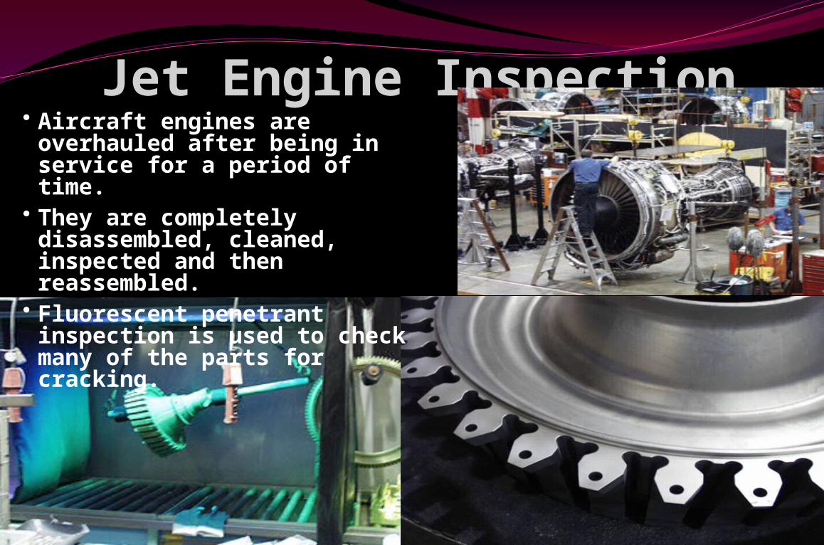
Jet Engine Inspection• Aircraft engines are overhauled after being in service for a period of time.
• They are completely disassembled, cleaned, inspected and then reassembled.
• Fluorescent penetrant inspection is used to check many of the parts for cracking.
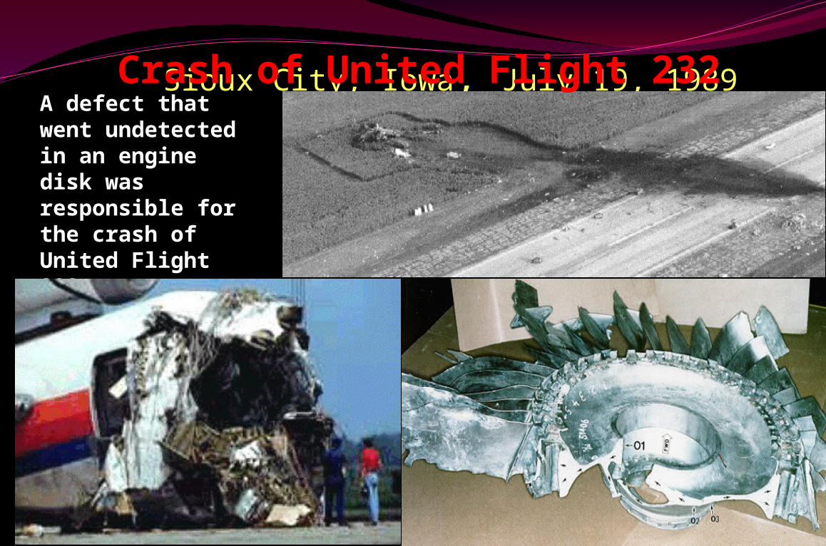
Sioux City, Iowa, July 19, 1989A defect that went undetected in an engine disk was responsible for the crash of United Flight 232.
Crash of United Flight 232
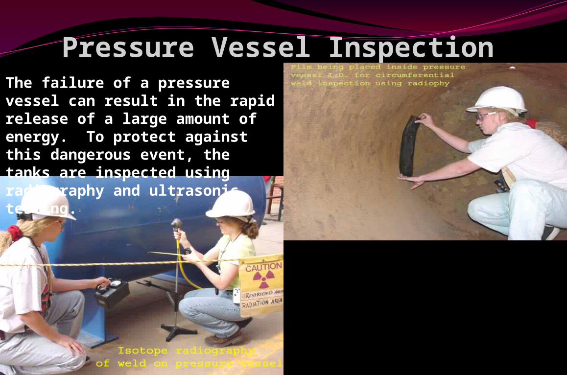
Pressure Vessel InspectionThe failure of a pressure vessel can result in the rapid release of a large amount of energy. To protect against this dangerous event, the tanks are inspected using radiography and ultrasonic testing.
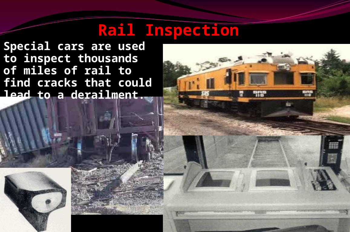
Rail InspectionSpecial cars are used to inspect thousands of miles of rail to find cracks that could lead to a derailment.
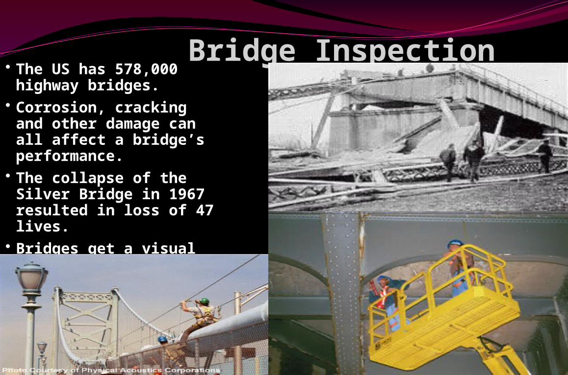
Bridge Inspection• The US has 578,000
highway bridges.• Corrosion, cracking
and other damage can all affect a bridge’s performance.
• The collapse of the Silver Bridge in 1967 resulted in loss of 47 lives.
• Bridges get a visual inspection about every 2 years.
• Some bridges are fitted with acoustic emission sensors that “listen” for sounds of cracks growing.
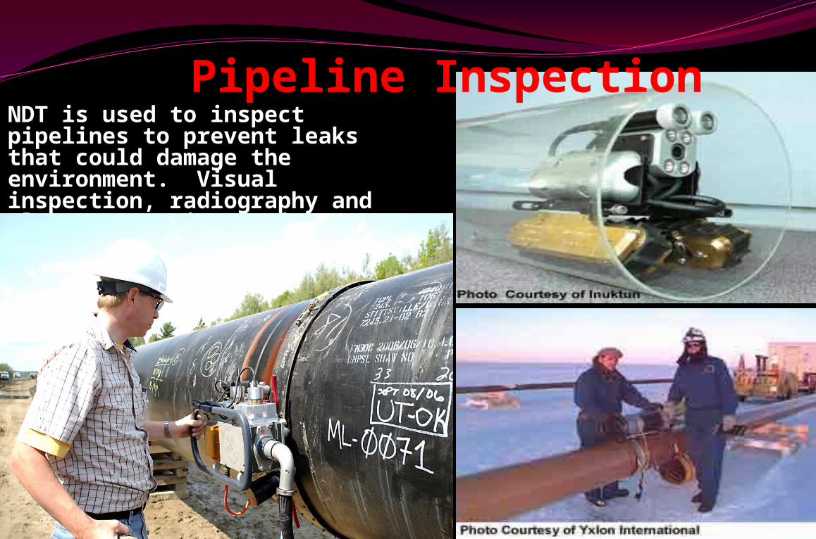
NDT is used to inspect pipelines to prevent leaks that could damage the environment. Visual inspection, radiography and electromagnetic testing are some of the NDT methods used.
Pipeline Inspection
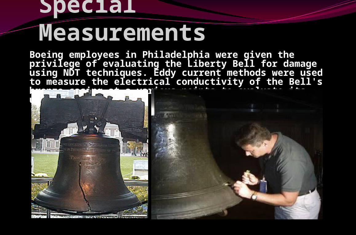
Special Measurements
Boeing employees in Philadelphia were given the privilege of evaluating the Liberty Bell for damage using NDT techniques. Eddy current methods were used to measure the electrical conductivity of the Bell's bronze casing at a various points to evaluate its uniformity.
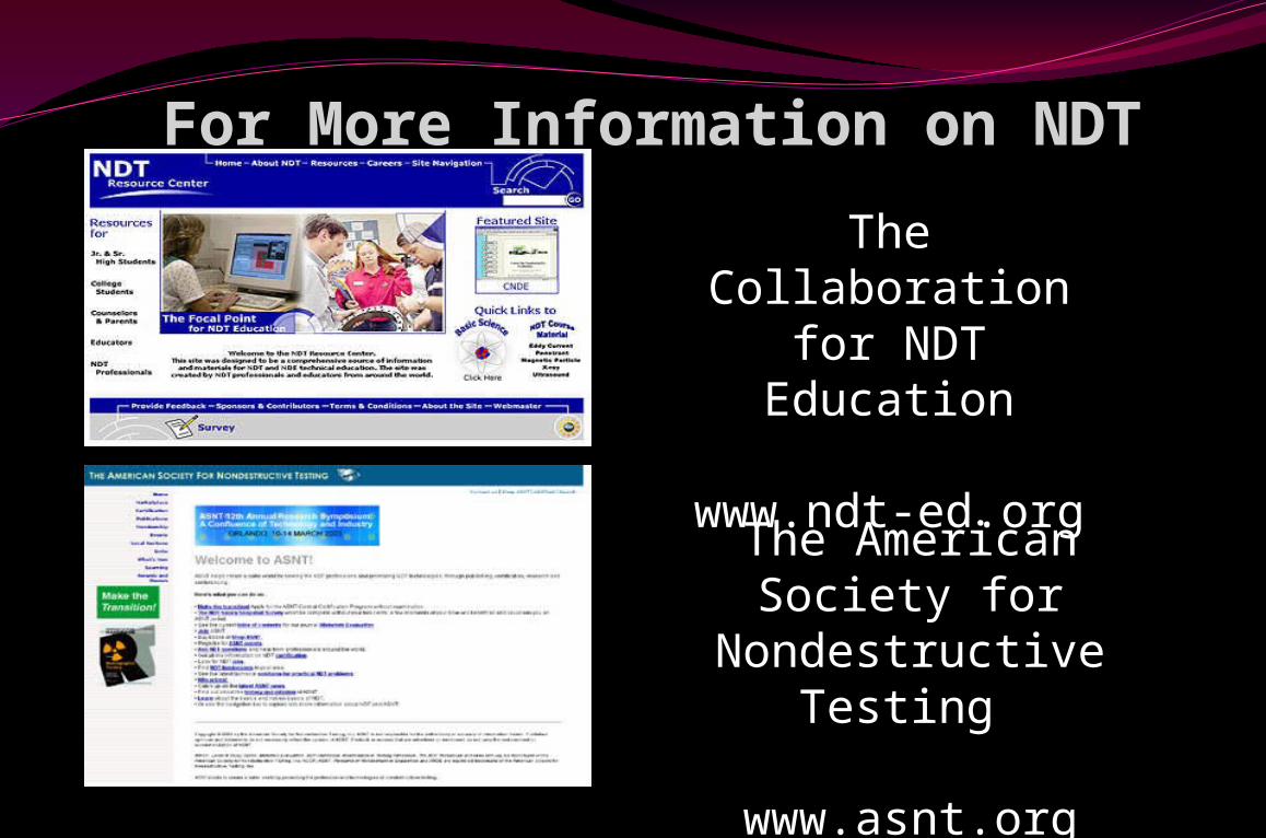
For More Information on NDT
The Collaboration for NDT Education
www.ndt-ed.org
The American Society for
Nondestructive Testing
www.asnt.org
Selection of the NDT methodsIn selecting the NDT method for the evaluation of
specific discontinuities keep in mind that NDT method may supplement each other & that several NDT methods may be capable of performing the same task. The selection of one method over another is based upon such variables as:
Type & origin of discontinuity
Material manufacturing processes
Accessibility of article
Level of acceptability desired
Equipment available
Cost
DEFINITIONS
Indication: A response or evidence of a response accruing non-destructive tests.
Discontinuities: Any condition, which breaks the continuity of the material/part, is called discontinuities.
While a discontinuity is an interruption in the normal structure of the part. It may not be defect if during the evaluation phase it is determined that the discontinuities interfere with the serviceability of the part or it does not meet the acceptance & rejection criteria. The discontinuity is then classified as a defect.
Defect: Any discontinuity, which interferes with the intended service of the material or part and is therefore objectionable, is called a defect.
ALL DISCONTINUITIES ARE NOT NECESSARILY DEFECTS. BUT DEFECTS ARE ALL NOT ACCEPTABLE DISCONTINUITIES
Interpretation: The determination of whether indications are relevant or non-relevant.
Evaluation: A determination of the significance of relevant indication. (Accept or Reject as per specification)
Relevant Indication: Relevant indications are those that are caused by discontinuities in part.
Non Relevant Indication: Non - relevant indications are caused by part configuration & they are not determine to the serviceability of the part.
Discontinuity are grouped into three categories
Inherent Discontinuity: Typical of melting, casting & solidification process.
Processing Discontinuity: Typical of mechanical working (Hot/cold) welding & heat treatment.
Service Discontinuity: Resulting due to interaction of stress temperature & environment.
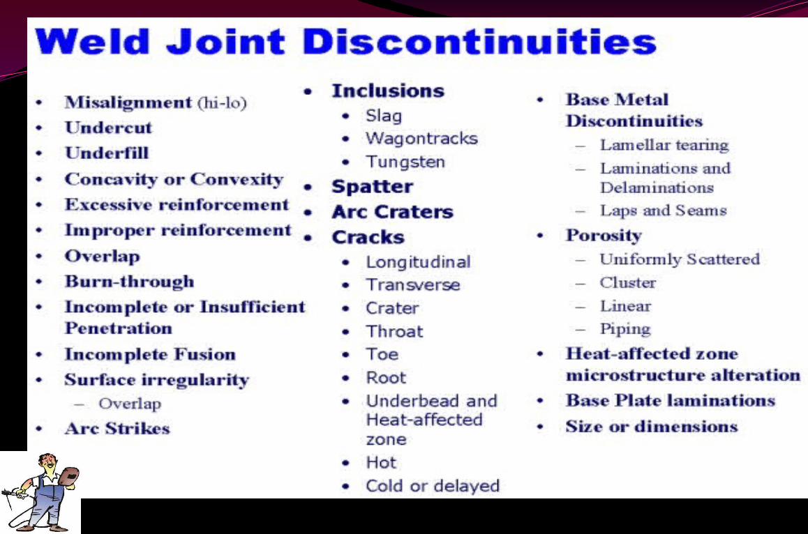
Type of Flaw Vs Severity Planar Flaws: Crack, LOF, LOP, Undercut & Root concavity
Volumetric Flaws: Burn through, Solid inclusion, Slag inclusion & Porosity
Weld Profile DefectsUndercut, Under fill, Overlap, Concavity, Convexity, Excess
reinforcement
Planar flaws are considered more severe than Volumetric flaws because of higher stress concentration associated with them
Flaw location Vs severity: Surface flaw is much more severe than internal flaws. This is because of higher stress intensity factor associated with surface flaw.
Interaction of adjacent flaw: As per ASME boiler & Pressure Vessel Code – XI. When the spacing between two adjacent flaw is less than average dimension of the two flaws, effective size is taken as the sum of the two flaw dimensions plus the gap between them.
ASME - BOILER AND PRESSURE VESSEL CODE SECTIONS
I. Power Boilers
II. Material specification Part A – Ferrous Material Part B – Non-ferrous Material Part C – Welding rods, Electrodes & Filler Metals Part D - Properties
III. Subsections NCA(Nuclear component) – General requirements for Division 1 & 2
IV. Construction of Heating Boilers
V. Non-destructive ExaminationVI. Recommended Rules for care & operation of heating boiler
VII. Recommended Rules for care of Power Boilers
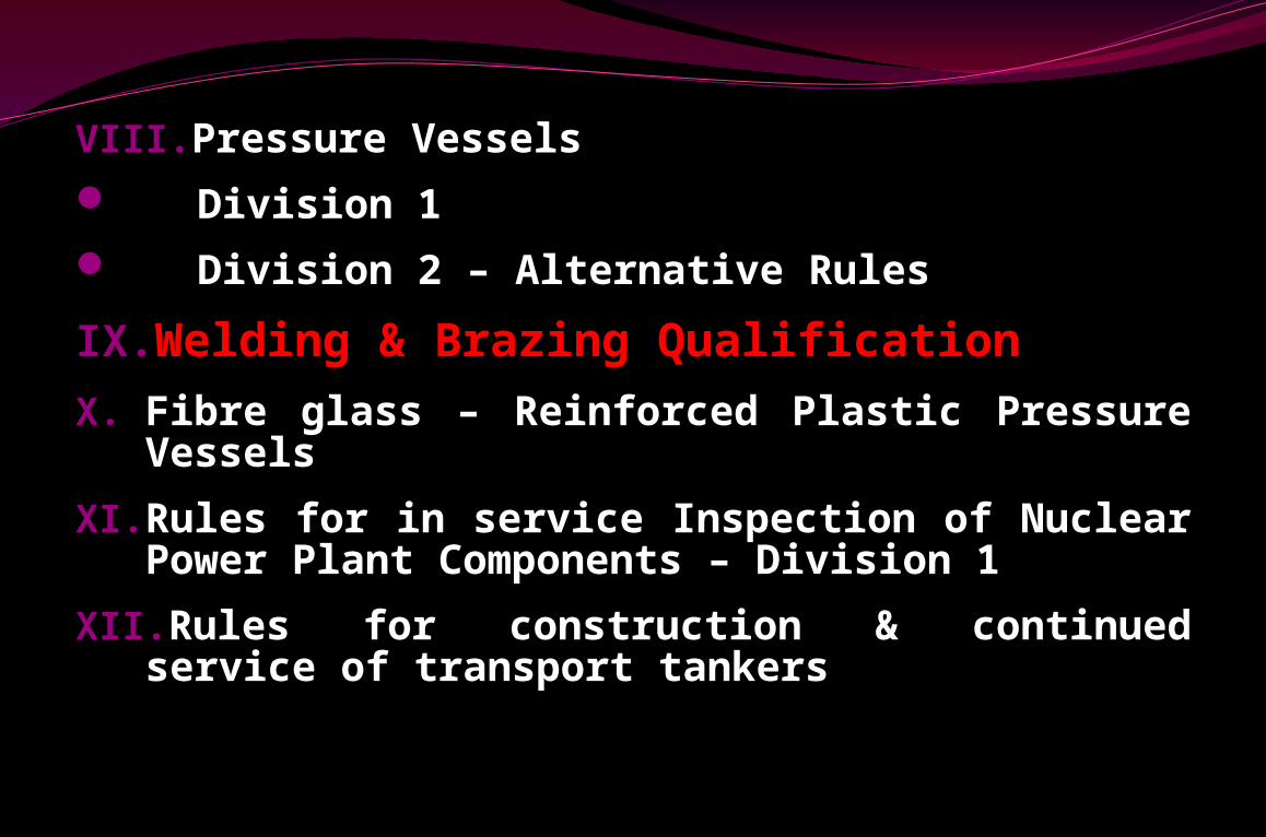
VIII.Pressure Vessels Division 1 Division 2 – Alternative Rules
IX.Welding & Brazing Qualification
X. Fibre glass – Reinforced Plastic Pressure Vessels
XI. Rules for in service Inspection of Nuclear Power Plant Components – Division 1
XII.Rules for construction & continued service of transport tankers
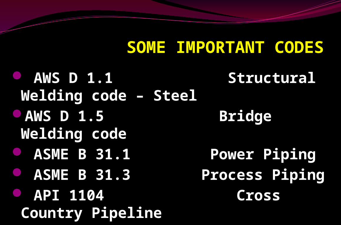
SOME IMPORTANT CODES
AWS D 1.1 Structural Welding code – Steel
AWS D 1.5 Bridge Welding code
ASME B 31.1 Power Piping ASME B 31.3 Process Piping API 1104 Cross Country Pipeline
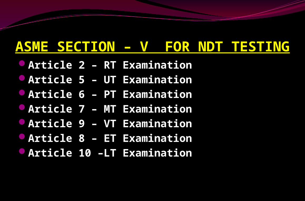
ASME SECTION – V FOR NDT TESTING Article 2 – RT ExaminationArticle 5 – UT ExaminationArticle 6 – PT ExaminationArticle 7 – MT ExaminationArticle 9 – VT ExaminationArticle 8 – ET ExaminationArticle 10 –LT Examination
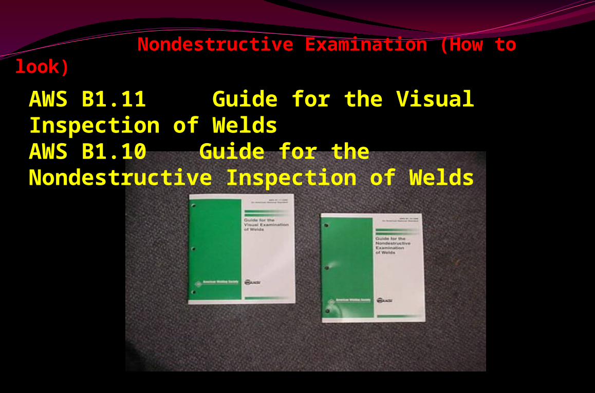
Nondestructive Examination (How to look)
AWS B1.11 Guide for the Visual Inspection of WeldsAWS B1.10 Guide for the Nondestructive Inspection of Welds
ARTICLES – 1
1)PERSONNEL
2)EQUIPMENT
3)PROCEDURE
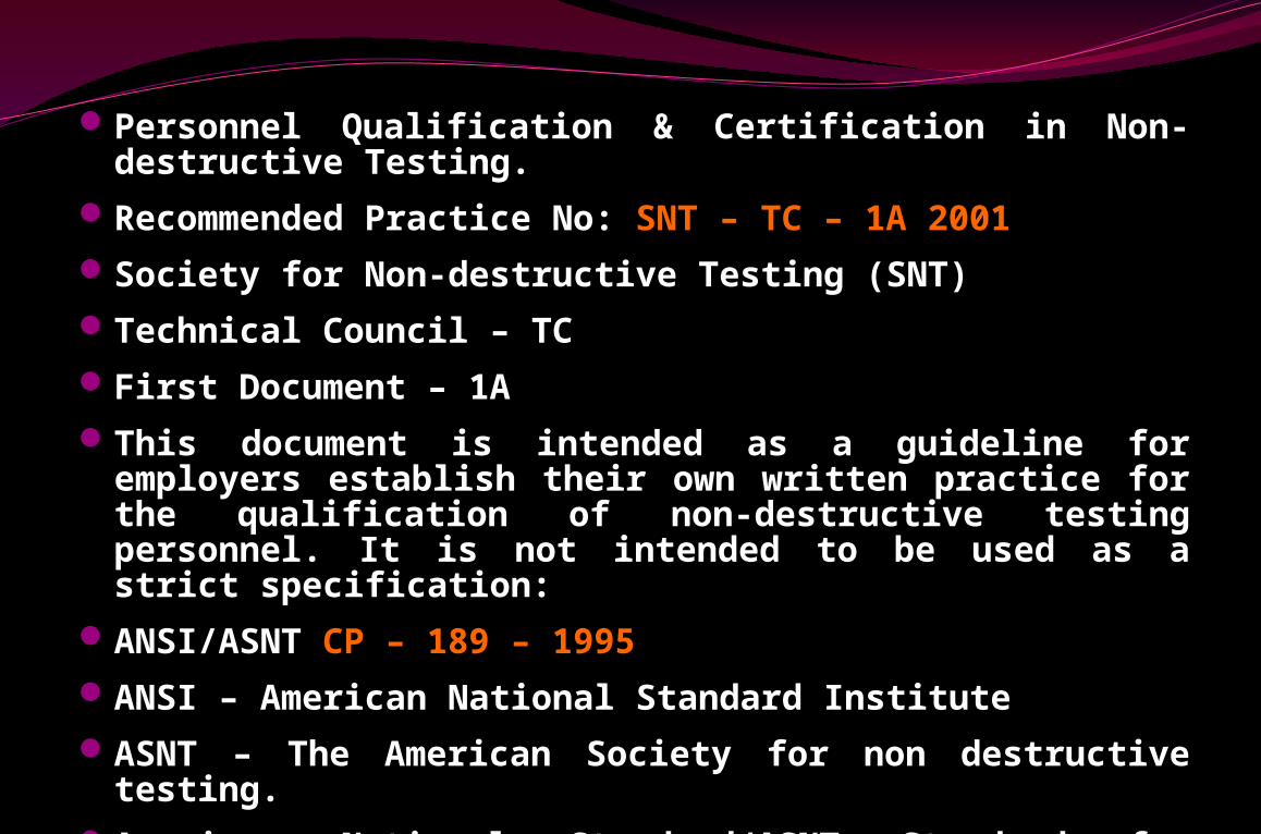
Personnel Qualification & Certification in Non-destructive Testing.
Recommended Practice No: SNT – TC – 1A 2001Society for Non-destructive Testing (SNT)Technical Council – TCFirst Document – 1AThis document is intended as a guideline for
employers establish their own written practice for the qualification of non-destructive testing personnel. It is not intended to be used as a strict specification:
ANSI/ASNT CP – 189 – 1995 ANSI – American National Standard InstituteASNT – The American Society for non destructive
testing.American National Standard/ASNT Standard for
Qualification & Certification of Non-destructive Testing Personnel.
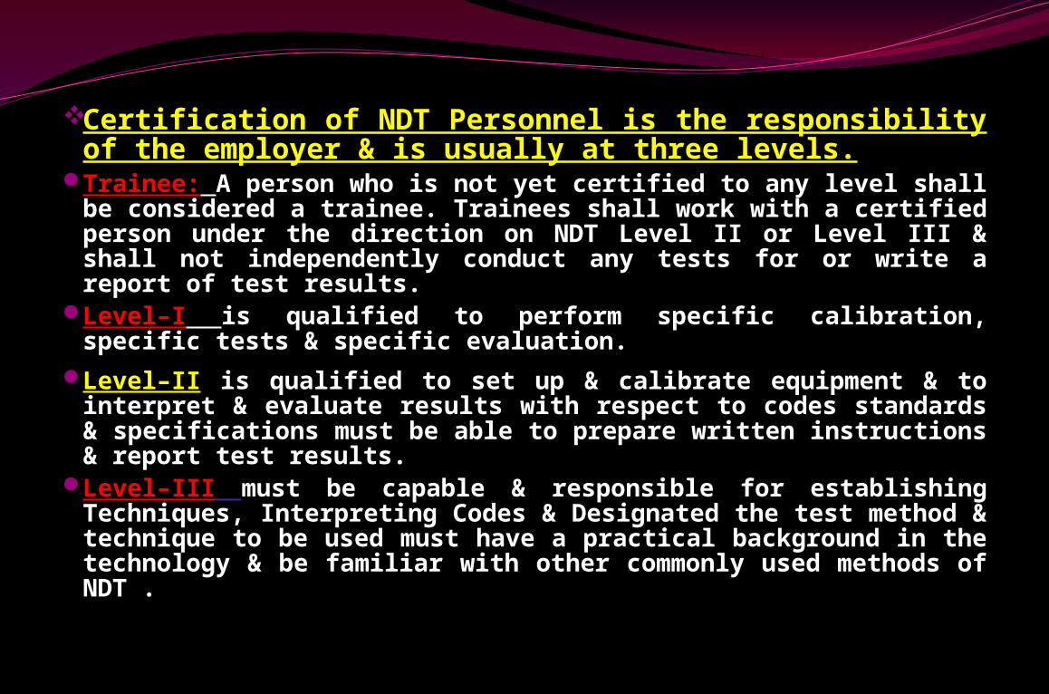
Certification of NDT Personnel is the responsibility of the employer & is usually at three levels.
Trainee: A person who is not yet certified to any level shall be considered a trainee. Trainees shall work with a certified person under the direction on NDT Level II or Level III & shall not independently conduct any tests for or write a report of test results.
Level–I is qualified to perform specific calibration, specific tests & specific evaluation.
Level–II is qualified to set up & calibrate equipment & to interpret & evaluate results with respect to codes standards & specifications must be able to prepare written instructions & report test results.
Level–III must be capable & responsible for establishing Techniques, Interpreting Codes & Designated the test method & technique to be used must have a practical background in the technology & be familiar with other commonly used methods of NDT .
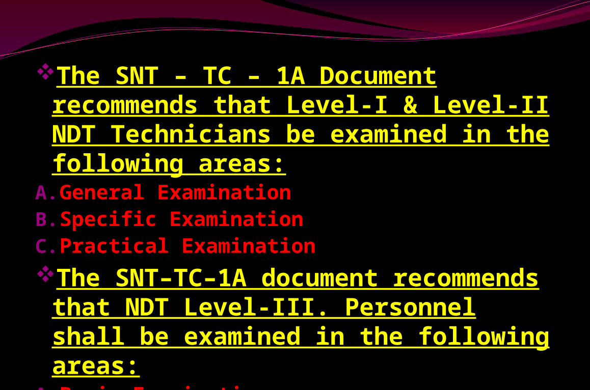
The SNT – TC – 1A Document recommends that Level-I & Level-II NDT Technicians be examined in the following areas:
A.General ExaminationB.Specific ExaminationC.Practical ExaminationThe SNT–TC–1A document recommends that NDT Level-III. Personnel shall be examined in the following areas:
A.Basic ExaminationB.Method ExaminationC.Specific Examination
Slide 4 of 81
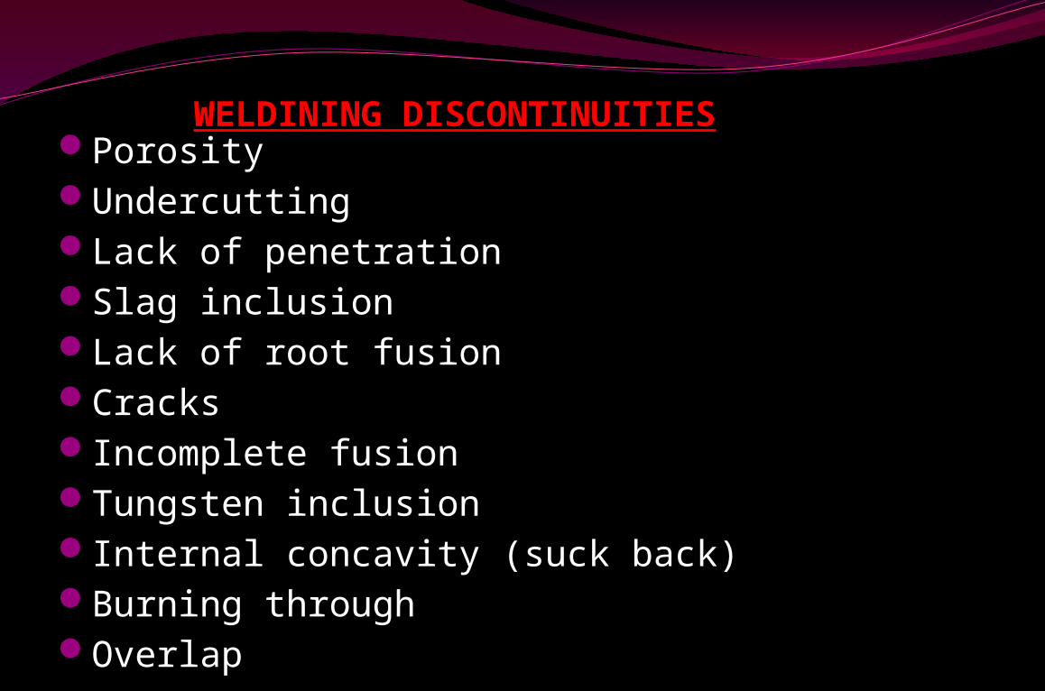
Porosity Undercutting Lack of penetrationSlag inclusion Lack of root fusion CracksIncomplete fusionTungsten inclusionInternal concavity (suck back)Burning throughOverlap
WELDINING DISCONTINUITIES
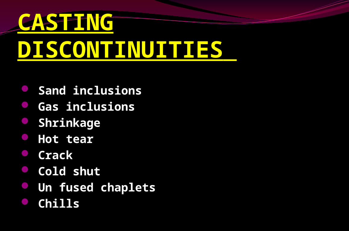
CASTING DISCONTINUITIES
Sand inclusions Gas inclusions Shrinkage Hot tear Crack Cold shut Un fused chaplets Chills
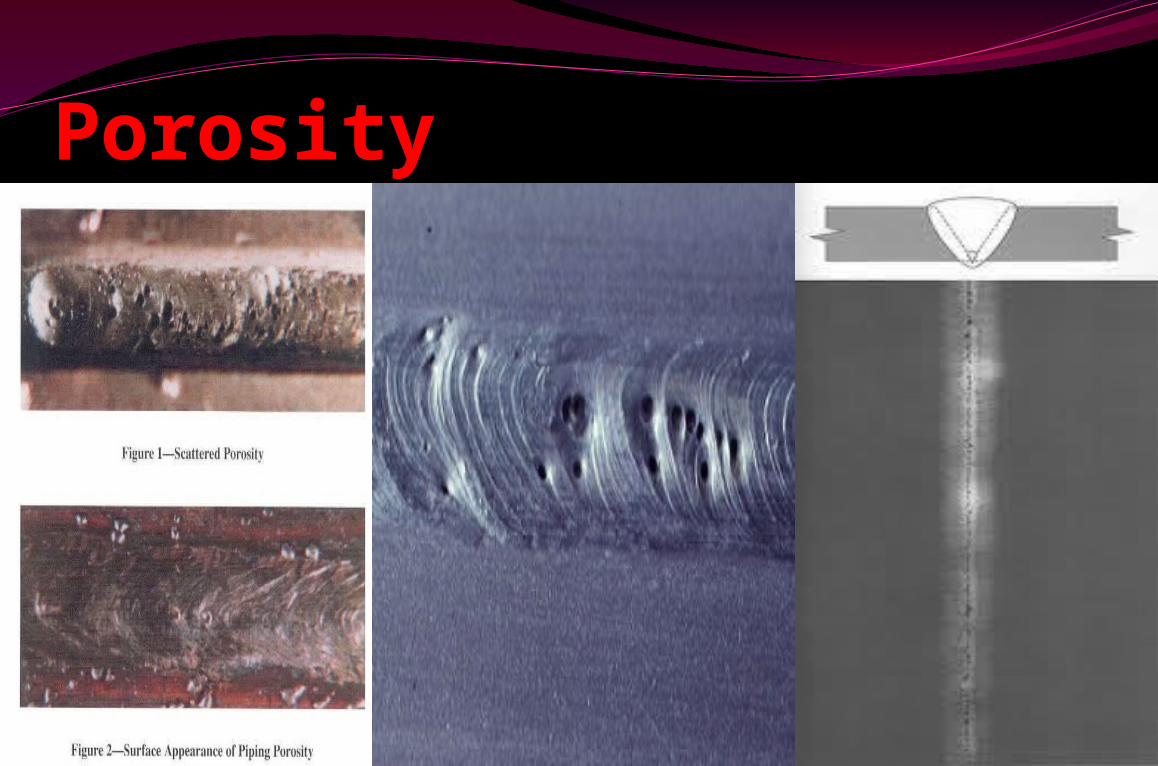
Porosity
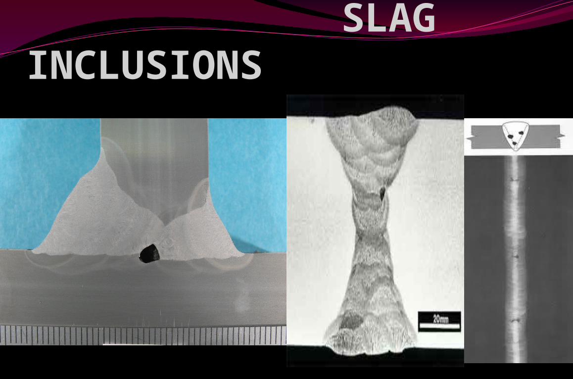
SLAG INCLUSIONS
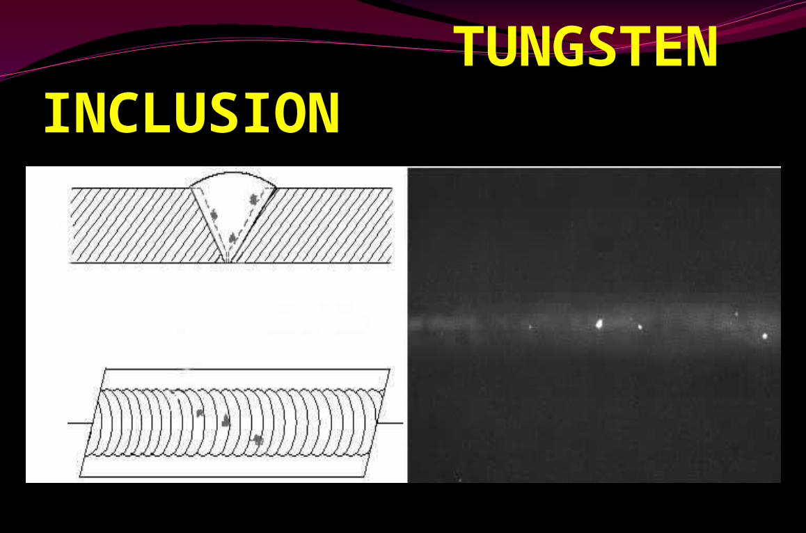
TUNGSTEN INCLUSION
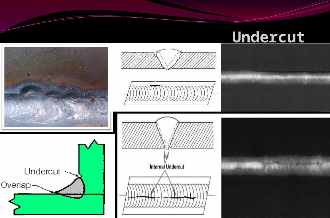
Undercut
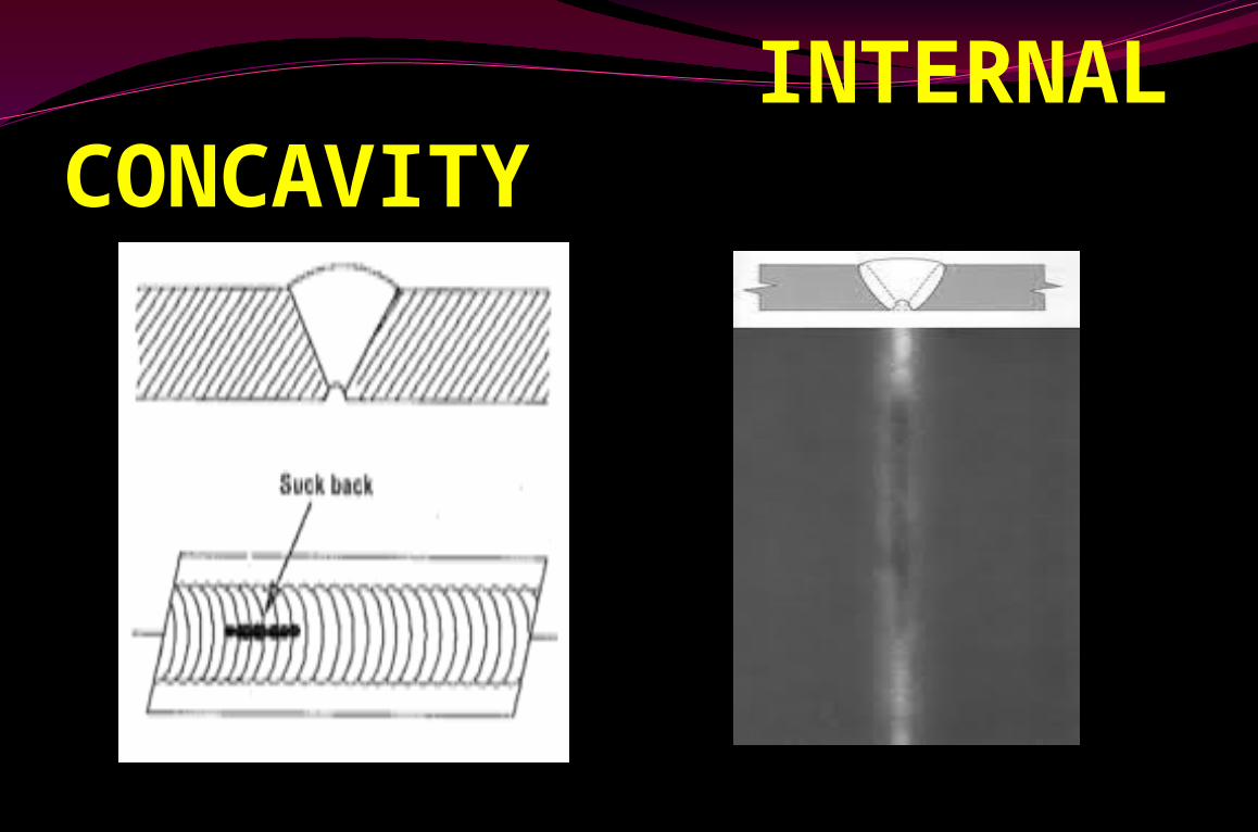
INTERNAL CONCAVITY
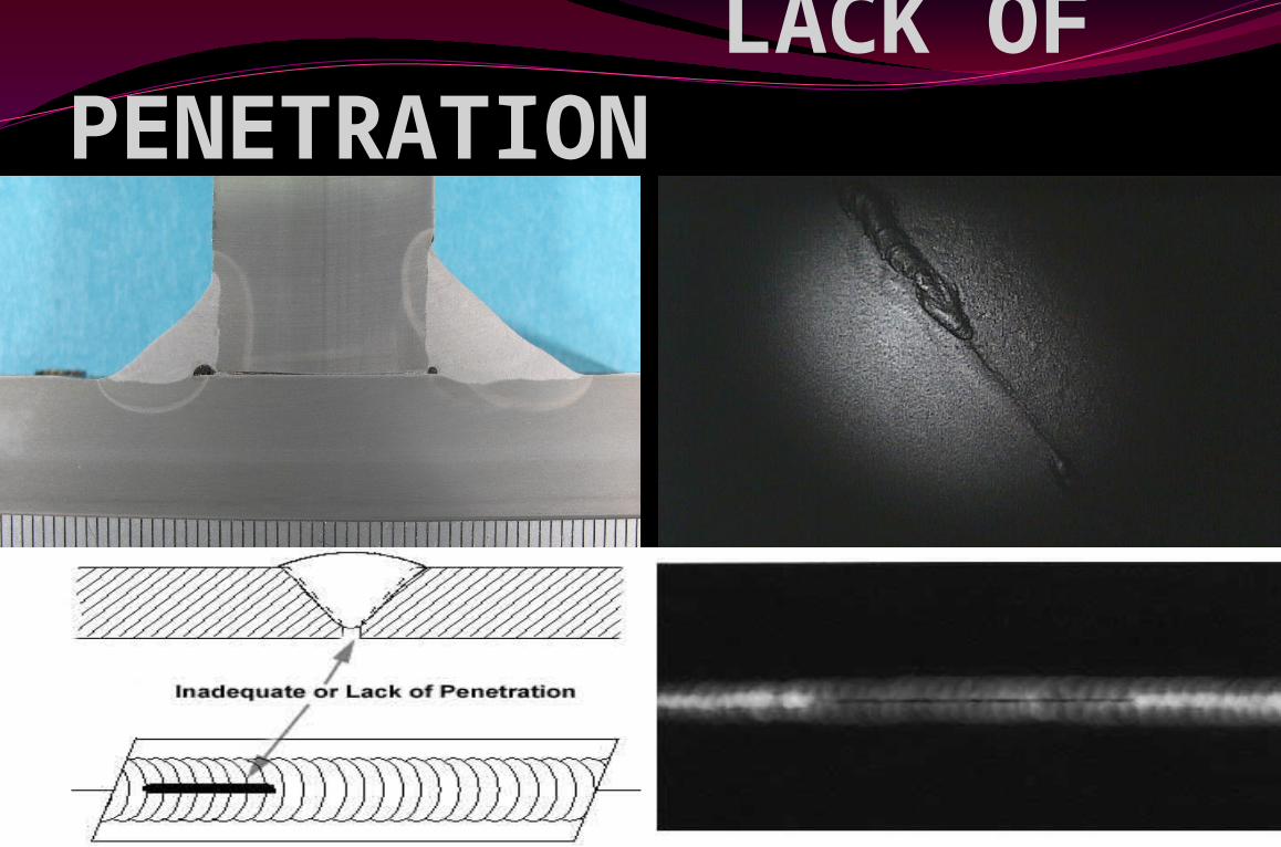
LACK OF PENETRATION
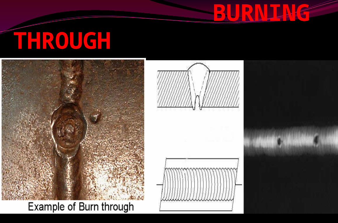
BURNING THROUGH
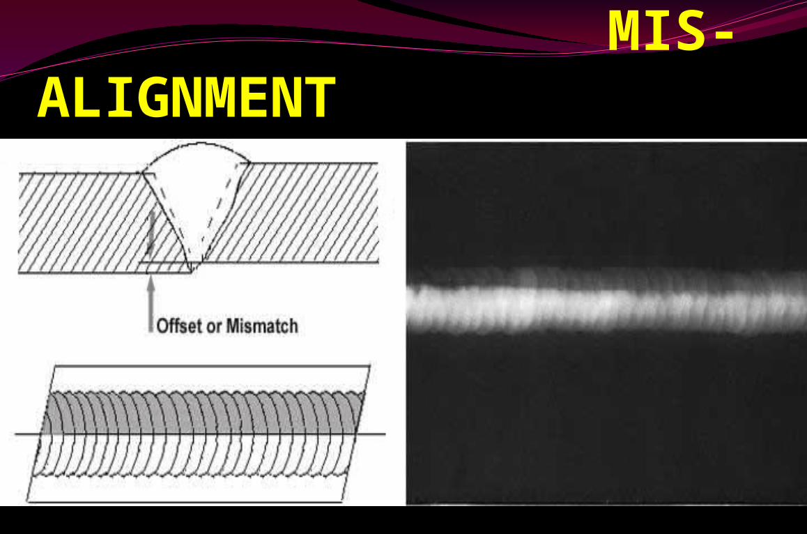
MIS-ALIGNMENT
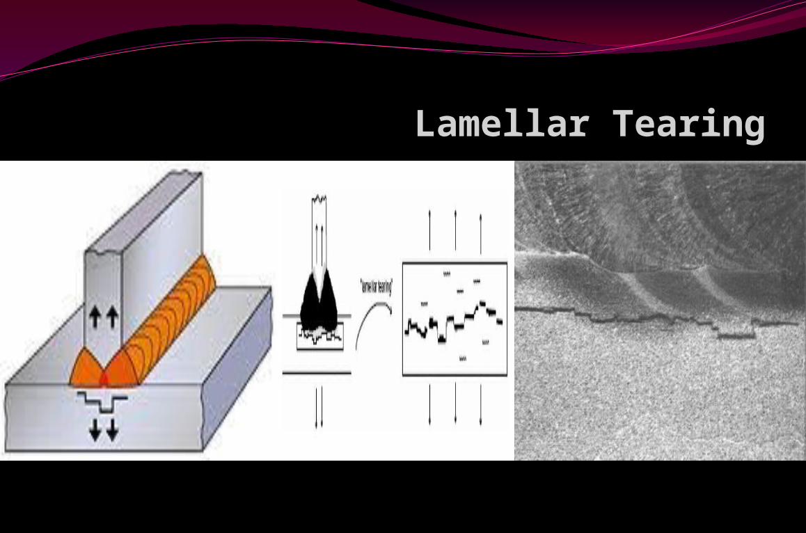
Lamellar Tearing
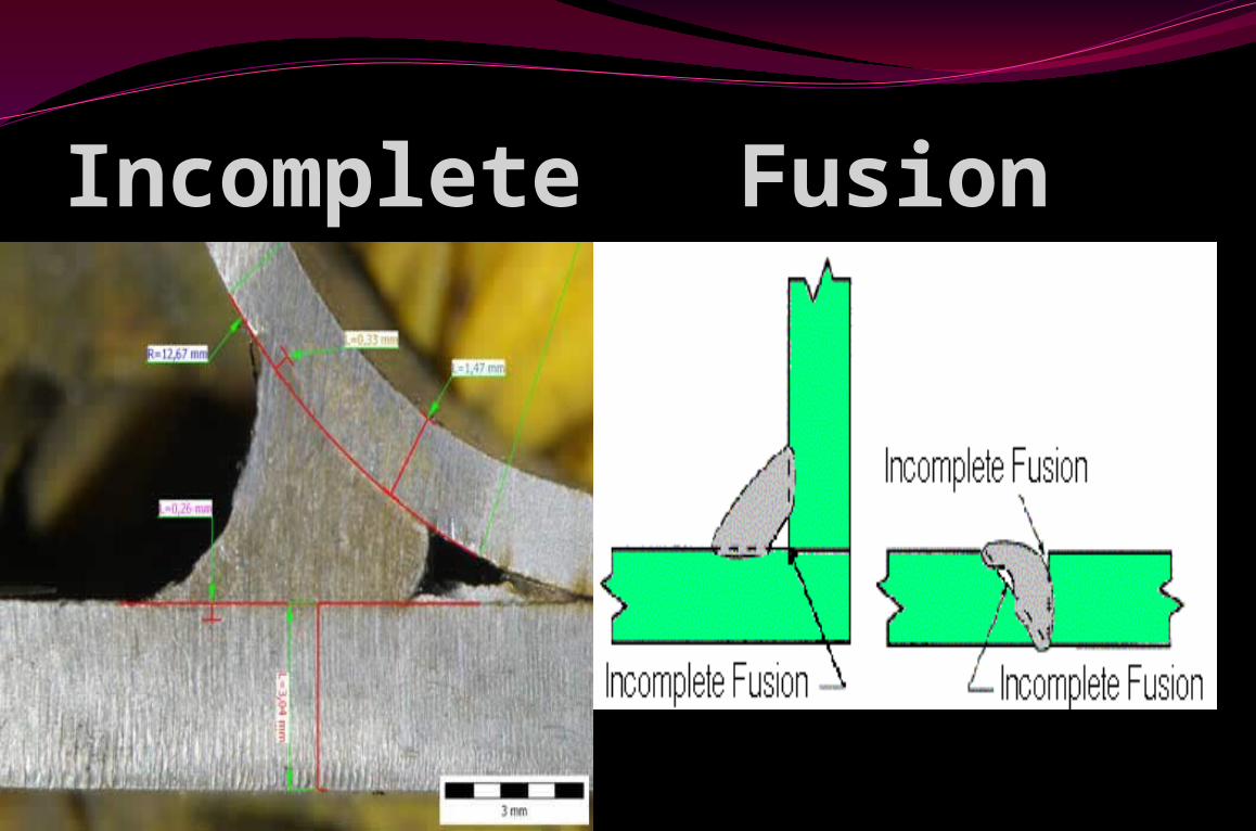
Incomplete Fusion
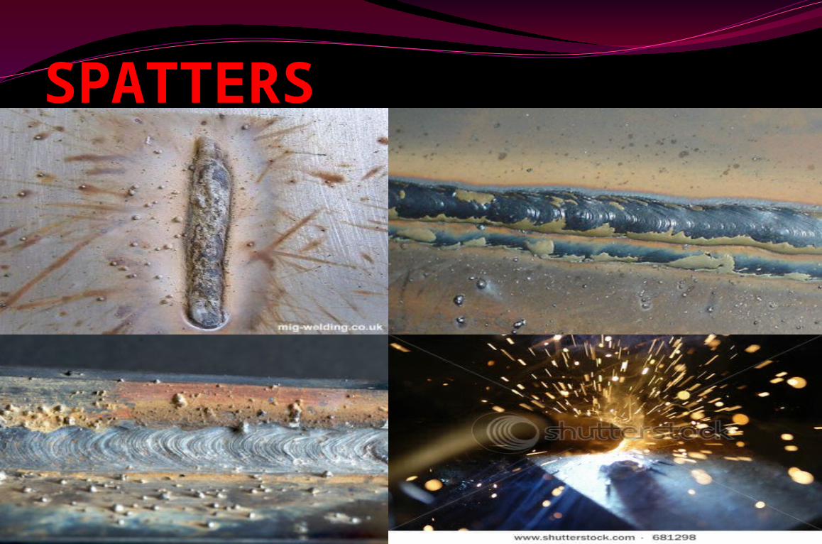
SPATTERS
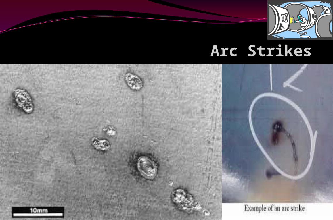
Arc Strikes
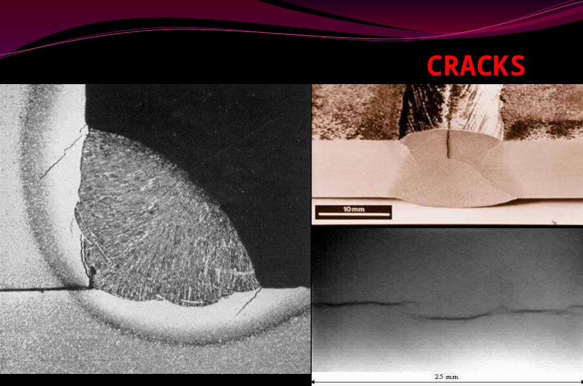
CRACKS
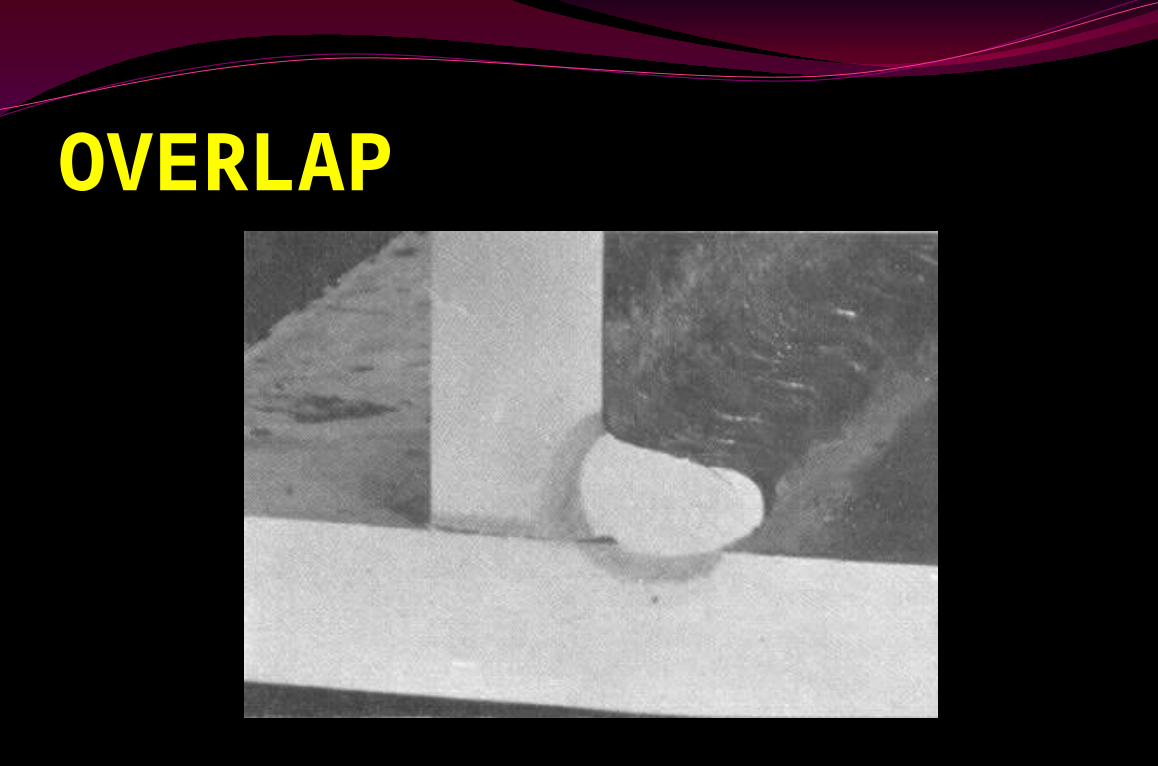
OVERLAP
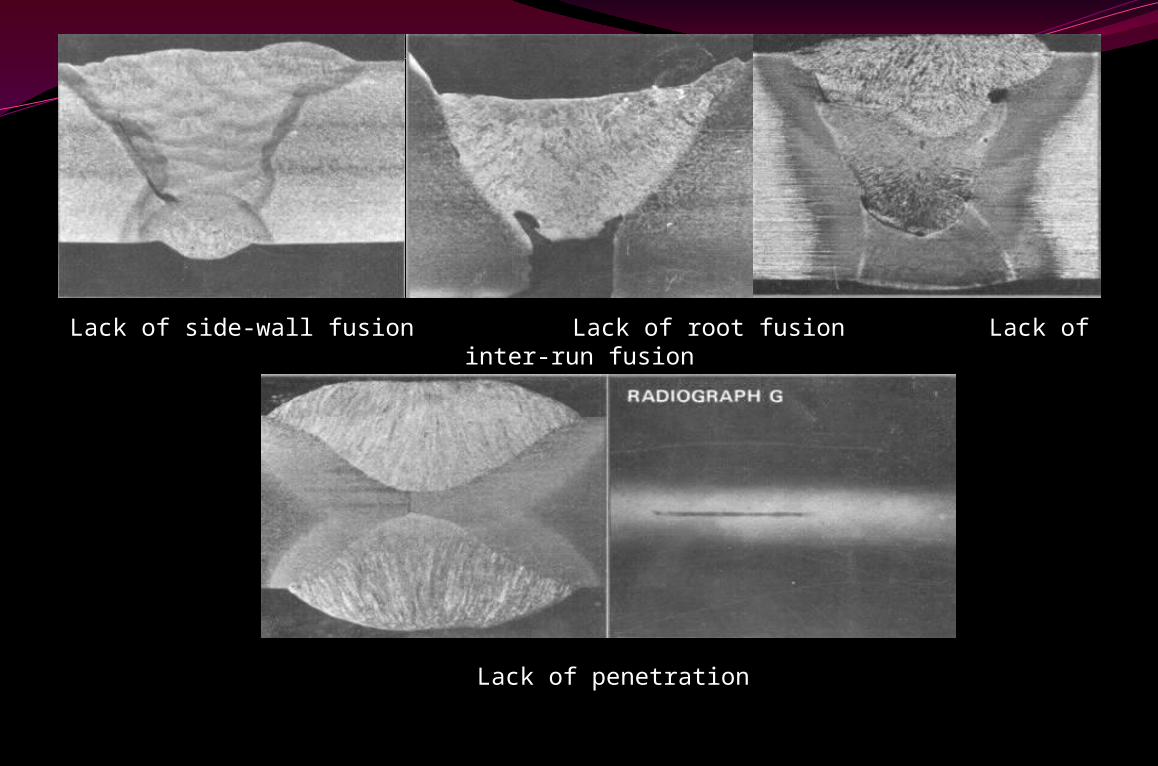
Lack of side-wall fusion Lack of root fusion Lack of inter-run fusion
Lack of penetration
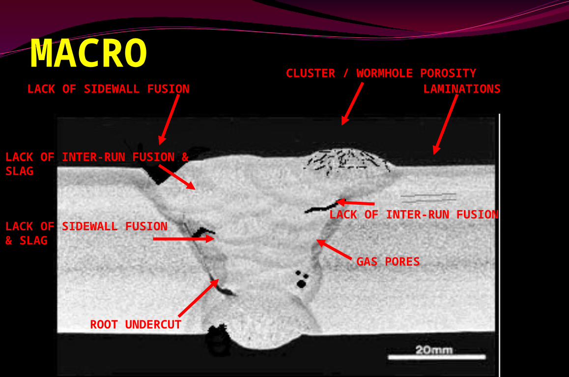
MACRO CLUSTER / WORMHOLE POROSITY LAMINATIONS
LACK OF INTER-RUN FUSION
ROOT UNDERCUT
GAS PORES
LACK OF SIDEWALL FUSION & SLAG
LACK OF INTER-RUN FUSION & SLAG
LACK OF SIDEWALL FUSION
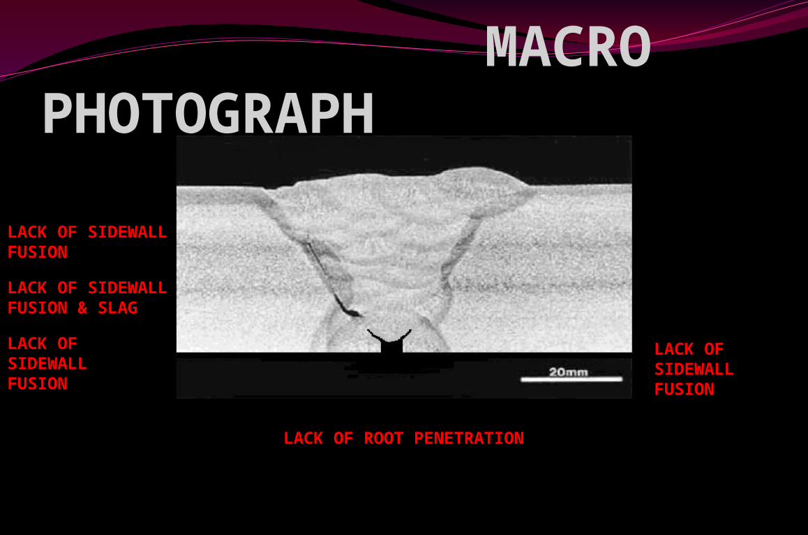
MACRO PHOTOGRAPH
LACK OF ROOT PENETRATION
LACK OF SIDEWALL FUSION
LACK OF SIDEWALL FUSION
LACK OF SIDEWALL FUSION & SLAG
LACK OF SIDEWALL FUSION
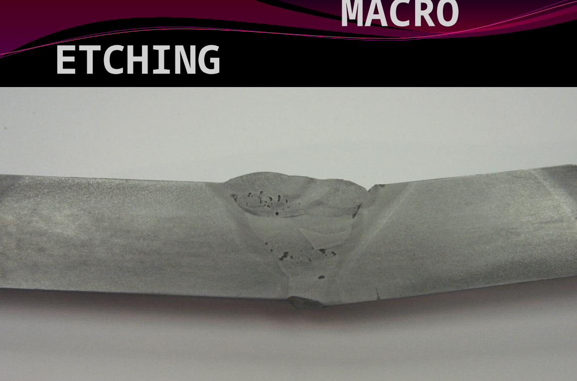
MACRO ETCHING
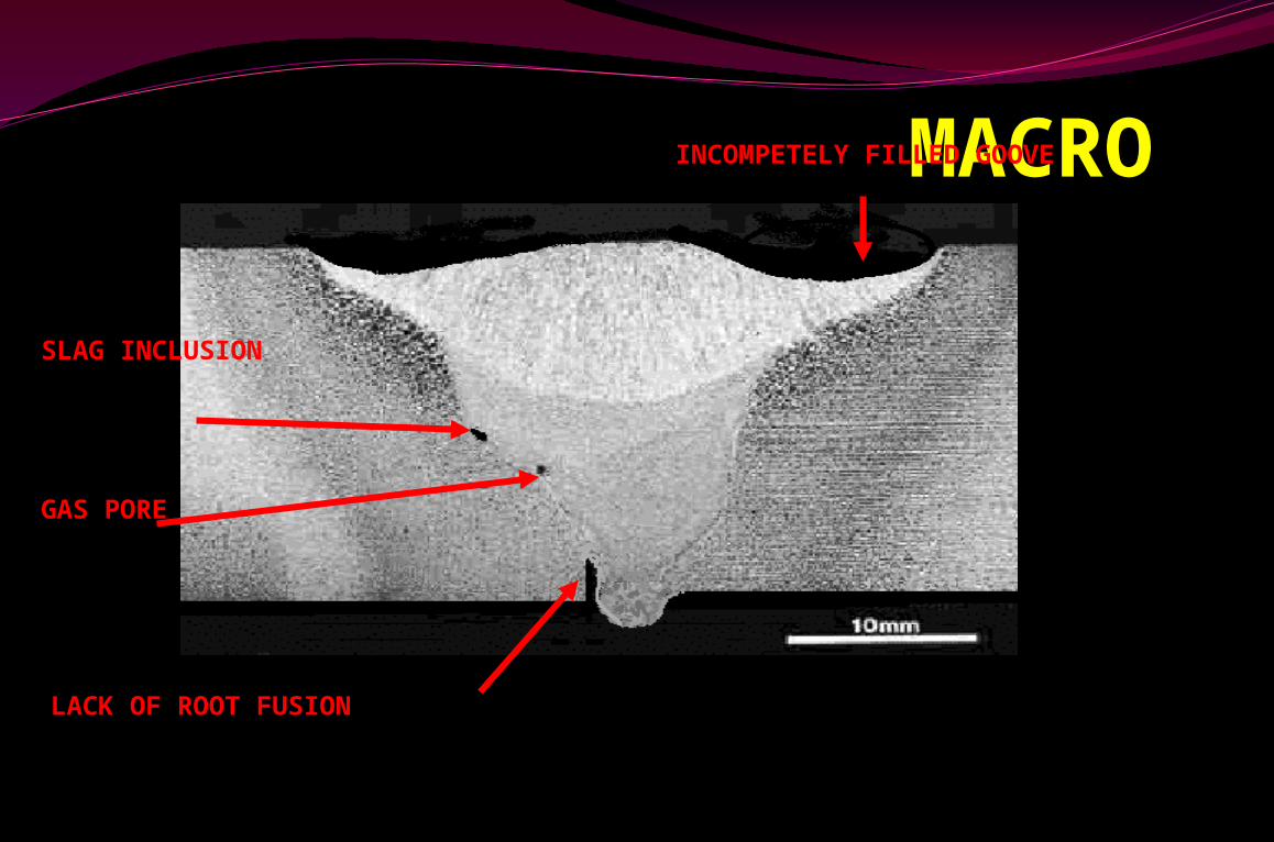
MACROINCOMPETELY FILLED GOOVE
LACK OF ROOT FUSION
SLAG INCLUSION
GAS PORE
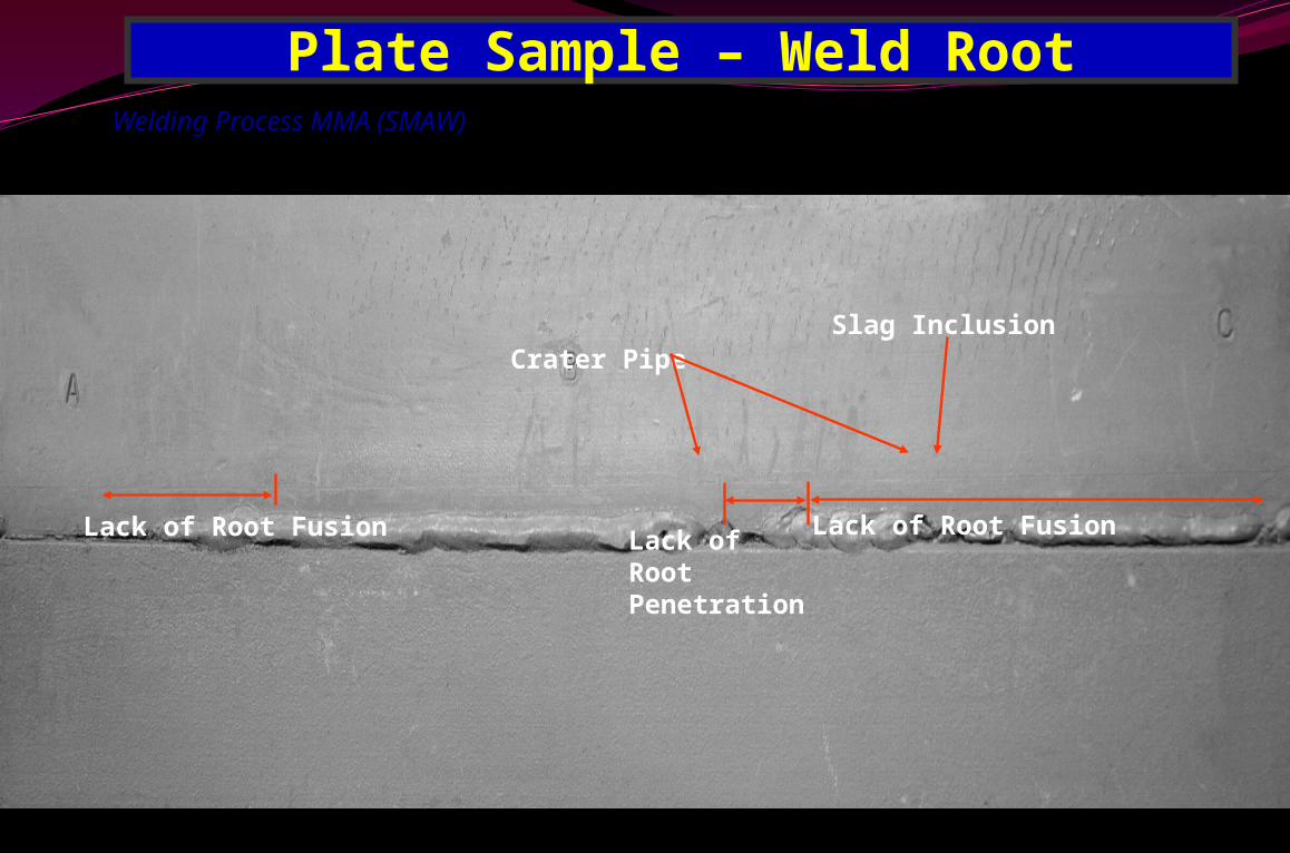
Lack of Root Fusion
Plate Sample – Weld Root
Lack of Root Fusion
Crater Pipe
Lack of Root Penetration
Slag Inclusion
Welding Process MMA (SMAW)
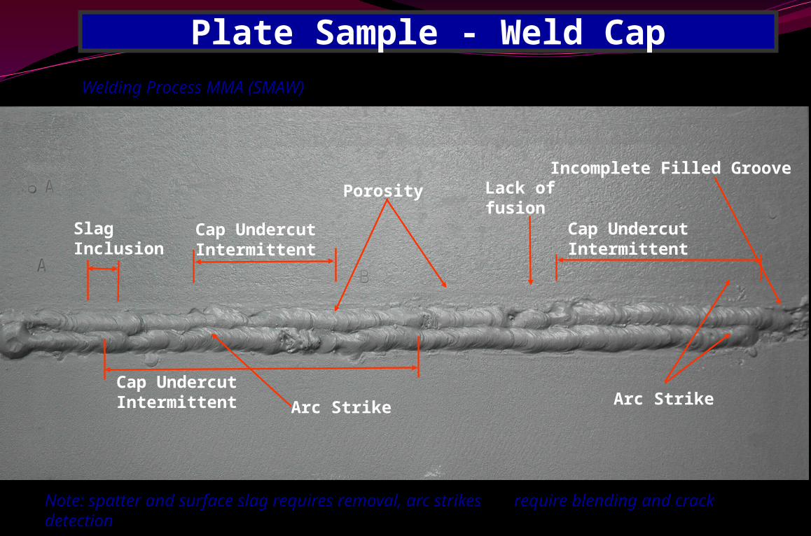
Plate Sample - Weld Cap
Cap Undercut Intermittent
Cap Undercut Intermittent
Slag Inclusion
Arc Strike
Porosity Lack of fusion
Cap Undercut Intermittent
Arc Strike
Incomplete Filled Groove
Note: spatter and surface slag requires removal, arc strikes require blending and crack detection
Welding Process MMA (SMAW)
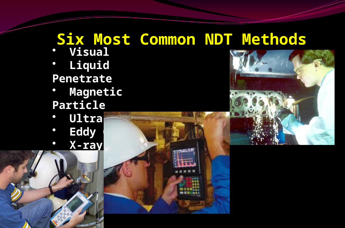
Six Most Common NDT Methods
• Visual• Liquid Penetrate • Magnetic Particle• Ultrasonic• Eddy Current• X-ray
Visual Inspection (VT)
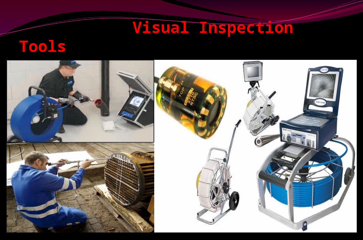
Visual Inspection Tools
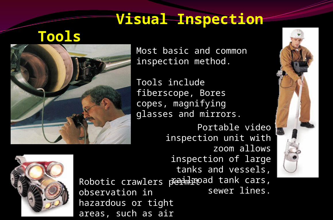
Most basic and common inspection method.
Tools include fiberscope, Bores copes, magnifying glasses and mirrors.
Robotic crawlers permit observation in hazardous or tight areas, such as air ducts, reactors, pipelines.
Portable video inspection unit with zoom allows
inspection of large tanks and vessels, railroad tank
cars, sewer lines.
Visual Inspection Tools

Visual Inspection Visual Inspection is the most & least
common inspection method
VT reveals spatter, excessive buildup, incomplete slag removal, cracks, Heat distortion, undercutting, Under fill, Dimensions& poor penetration ..
Typical tools for VT consist of Fillet gauges Magnifying glasses, Flashlights, Bores copes & Tape measures or calipers.
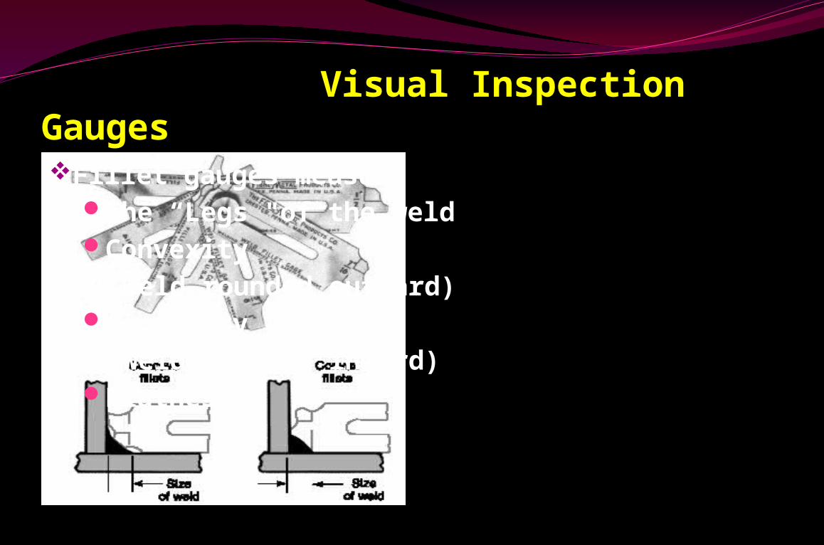
Visual Inspection GaugesFillet gauges measure
The “Legs "of the weld Convexity
(weld rounded outward) Concavity
(weld rounded inward)Flatness
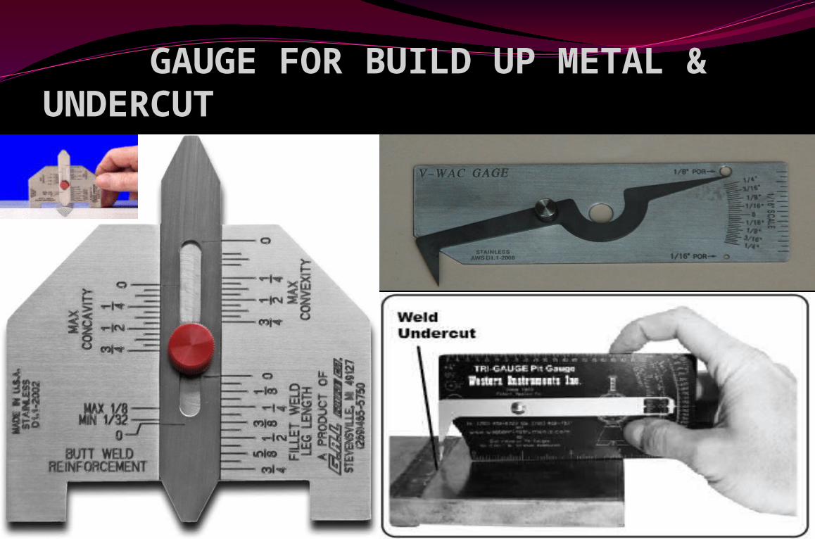
GAUGE FOR BUILD UP METAL & UNDERCUT
Visual Examination Advantages Disadvantages
EasyQuickInexpensiveComprehensiveSimple tool
• Requires experience
Need clean, lighted area
Surface onlyGood Eye Vision
Needs
Surface Inspection
Dye Penetrate Inspection
Visual Inspection.
Sub-surface Inspection
Magnetic Particle Inspection
Eddy Current Inspection
.
Internal Inspection
Ultrasonic InspectionRadiographic Inspection
.
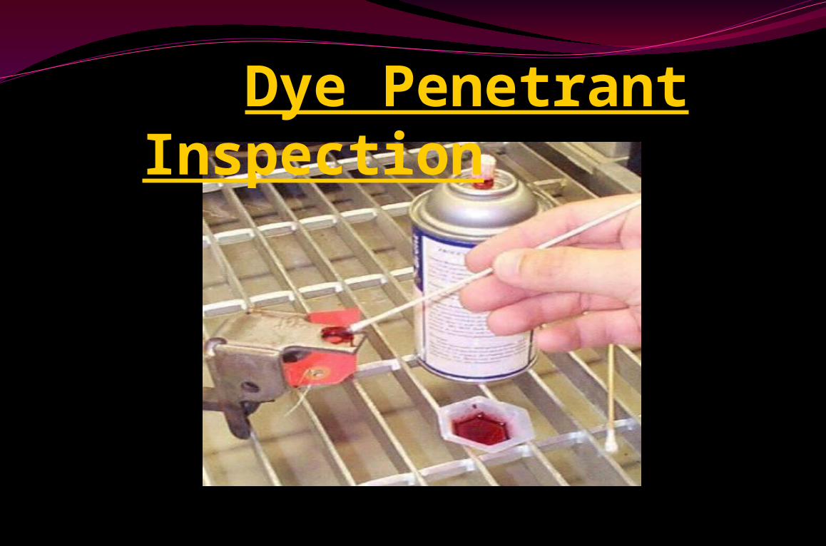
Dye Penetrant Inspection
Liquid Penetrant Inspection
Dye Penetrant Inspection (DPI)
Penetrant Flaw Detection (PFD)
Penetrant Testing (PT)
Liquid Penetrant Testing (LPT)
Liquid Penetrant Inspection Only for Surface breaking flaw inspection Applicable to all Non-porous, Non-absorbing
materials Liquid penetrant inspection uses colored or
fluorescent dye to check for surface flaws PT will not show sub-surface flaws PT can be used on Both metallic and Non -
metallic surfaces such as Ceramic, Glass, Plastic and Metal
PT dose not require the part to be Magnetized.
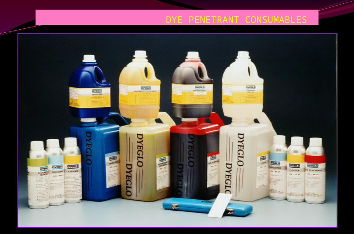
DYE PENETRANT CONSUMABLES
PROCESS FLOW CHAT Surface preparation Penetrant application Dwell Time Removal of excess penetrant Drying (Not universally required) Application of developer Inspection Post cleaning and protection
Penetrant Examination
BASIC PRINCIPLE – CAPILLARY ACTION
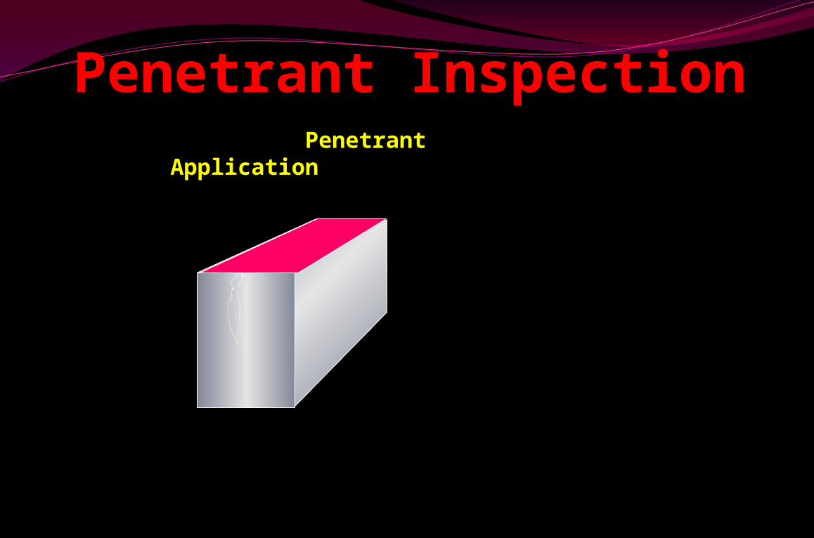
Penetrant Inspection Penetrant Application
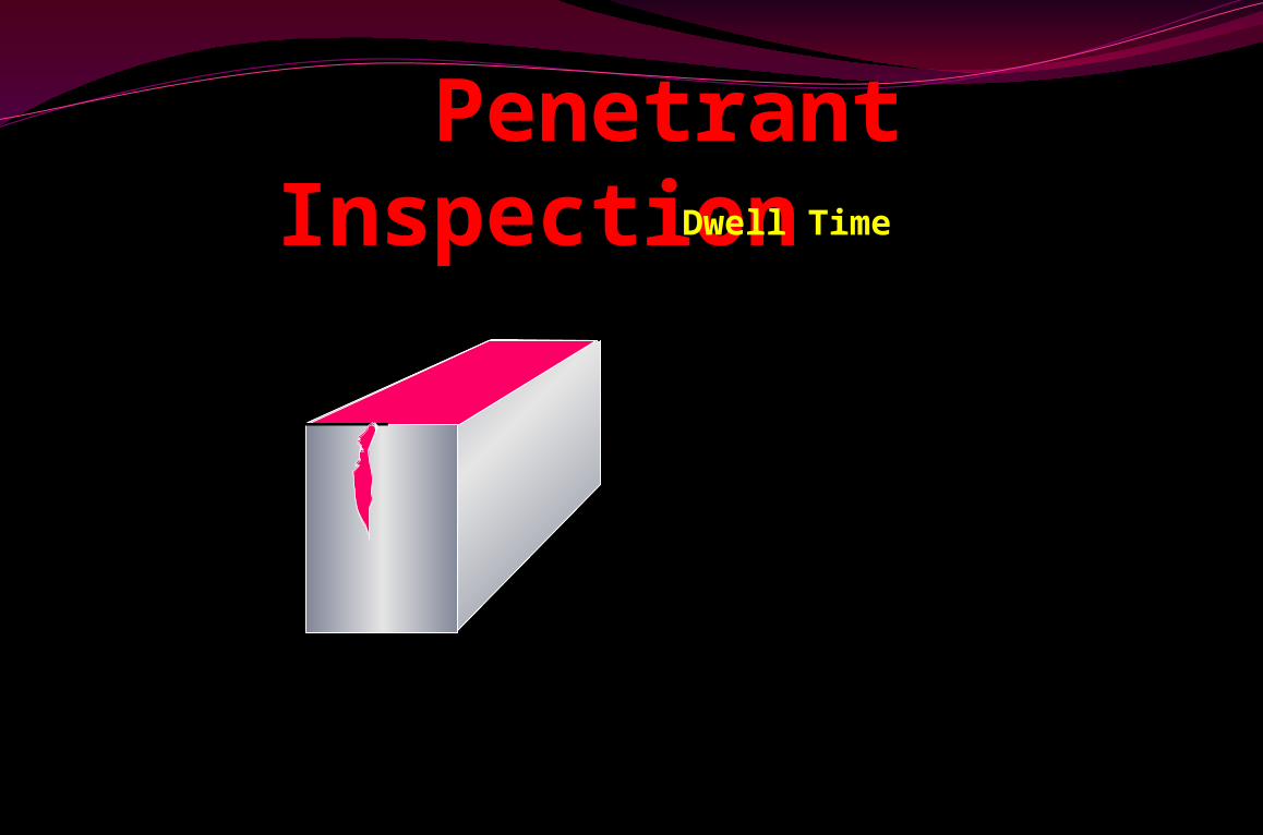
Penetrant Inspection Dwell Time
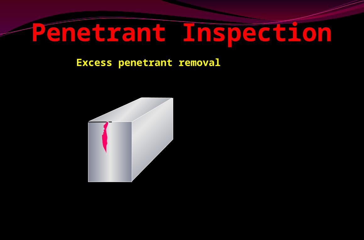
Excess penetrant removal
Penetrant Inspection

Developer application
Penetrant Inspection
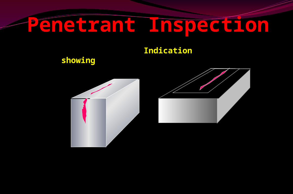
Indication showing
Penetrant Inspection
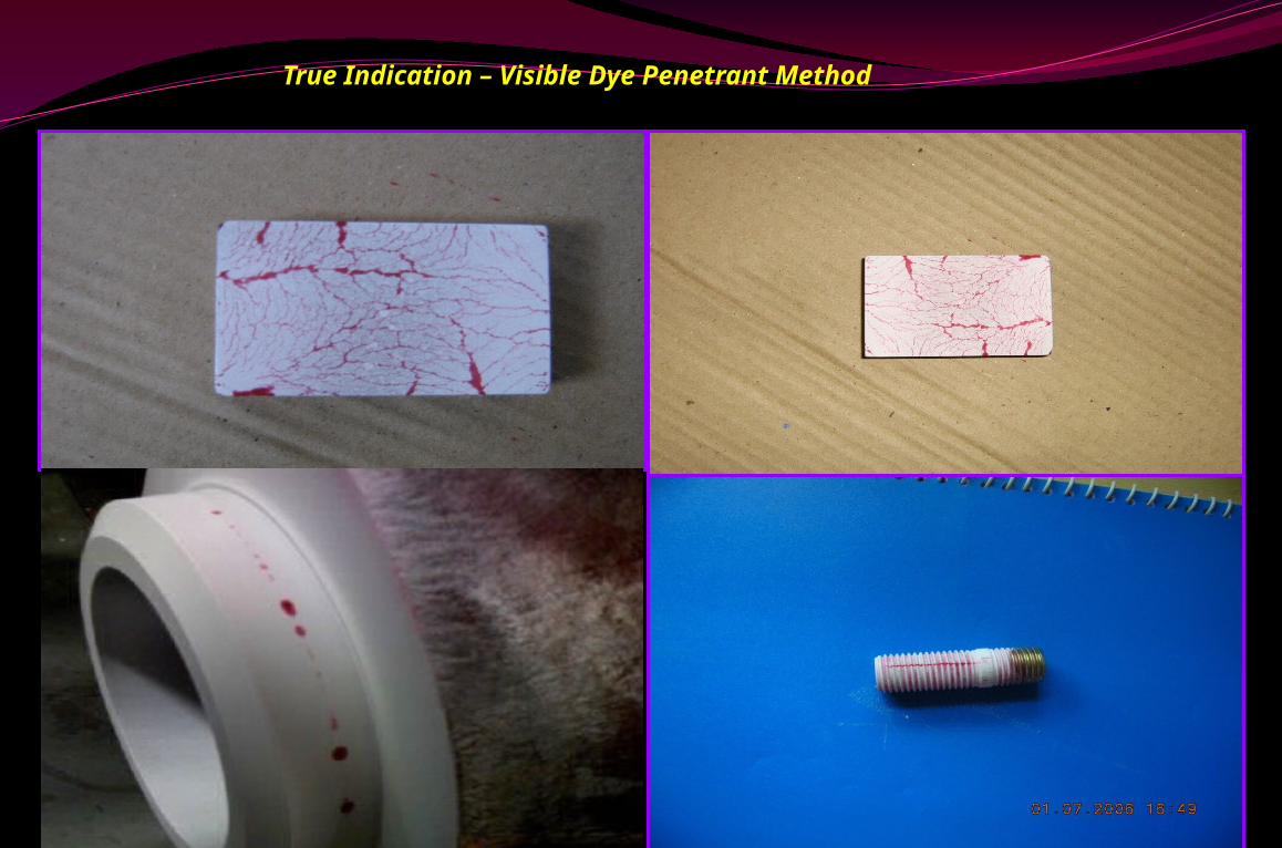
True Indication – Visible Dye Penetrant Method
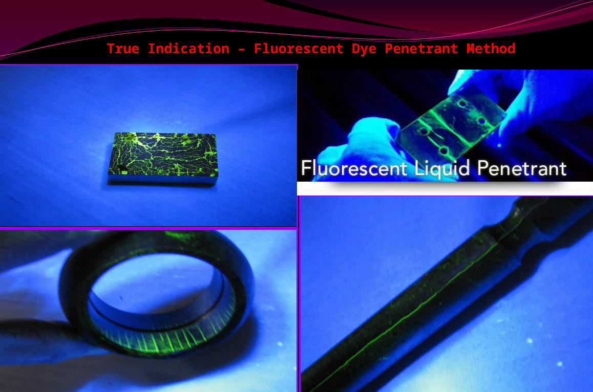
True Indication – Fluorescent Dye Penetrant Method
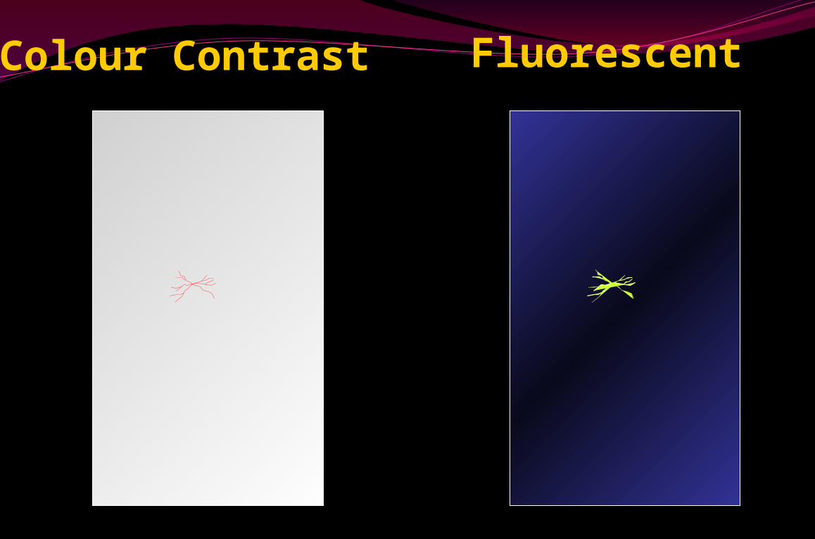
Colour Contrast Fluorescent
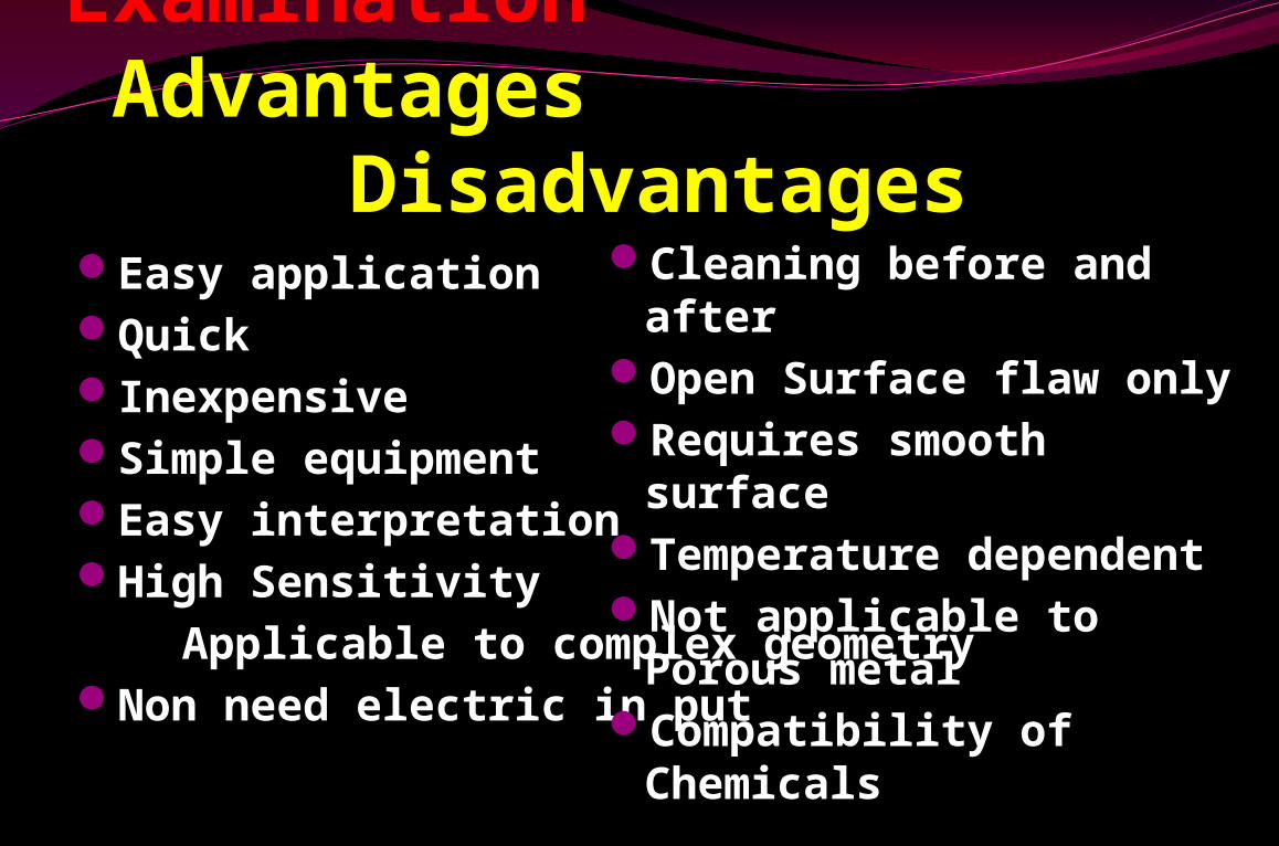
Penetrant Examination Advantages DisadvantagesEasy applicationQuickInexpensiveSimple equipmentEasy interpretationHigh Sensitivity Applicable to complex geometryNon need electric in put
Cleaning before and after
Open Surface flaw onlyRequires smooth
surfaceTemperature
dependentNot applicable to
Porous metalCompatibility of
Chemicals
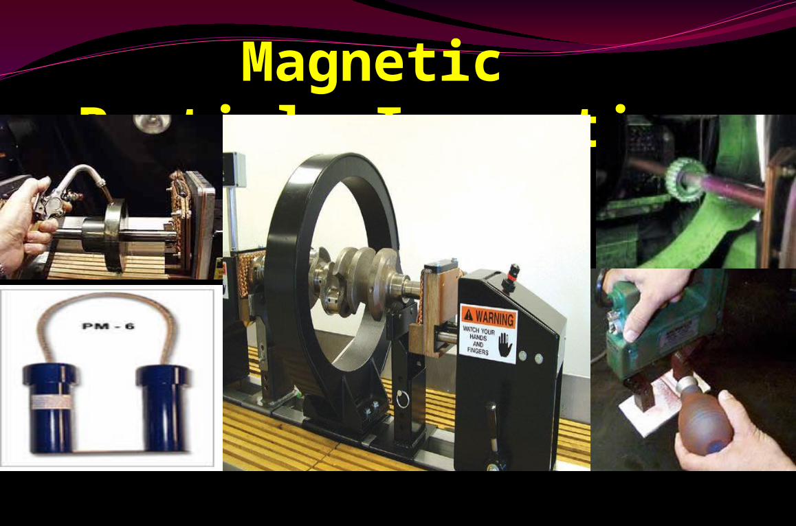
Magnetic Particle Inspection
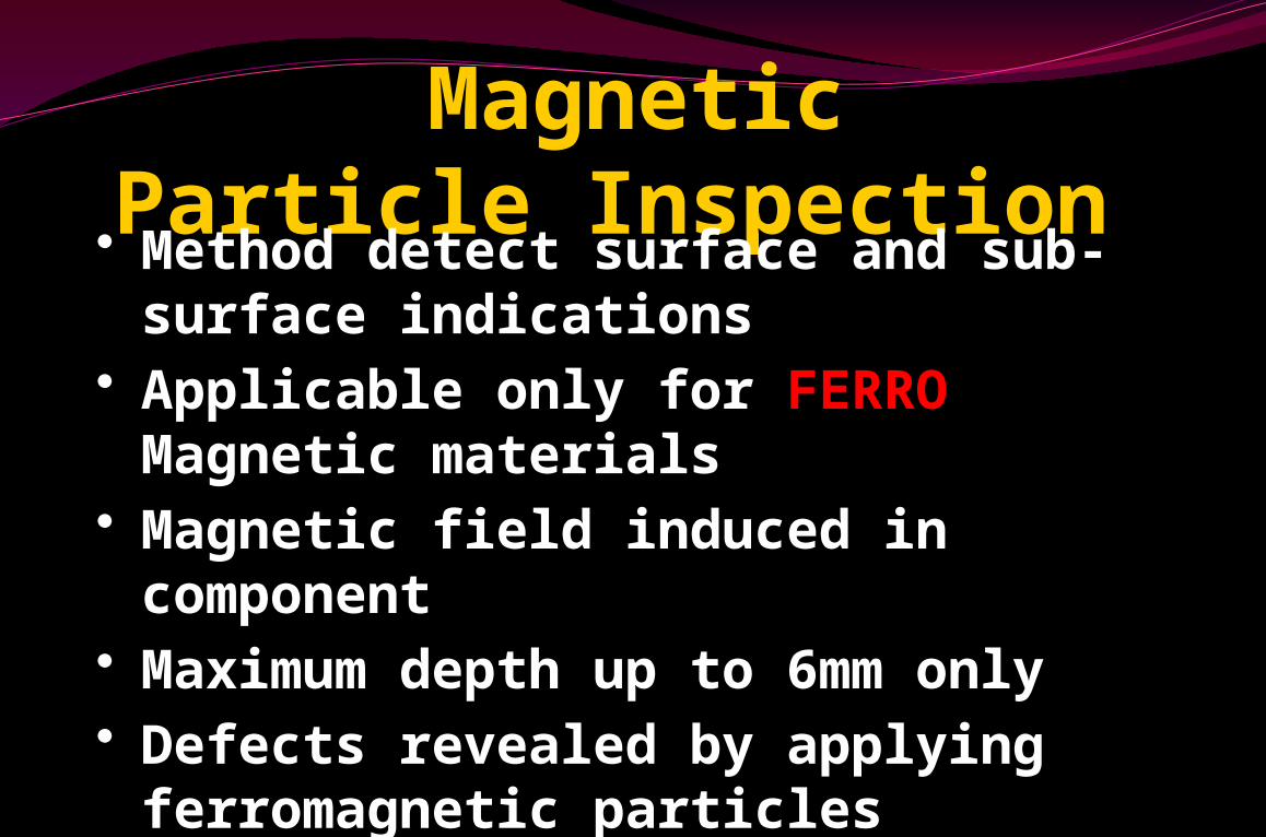
Magnetic Particle Inspection• Method detect surface and sub-surface indications
• Applicable only for FERRO Magnetic materials
• Magnetic field induced in component
• Maximum depth up to 6mm only • Defects revealed by applying
ferromagnetic particles• At cracks, magnetic field “leaks”• Also Named as MAGNA FLUX
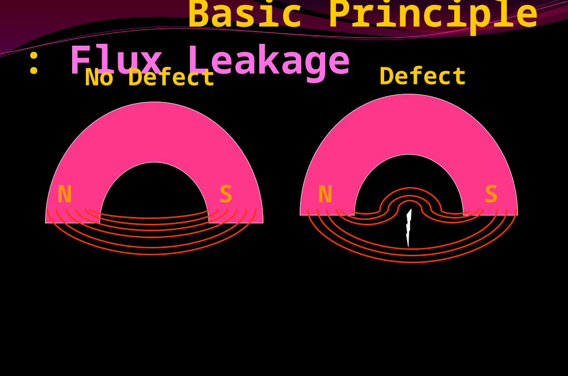
Basic Principle : Flux Leakage
N S SN
No Defect Defect
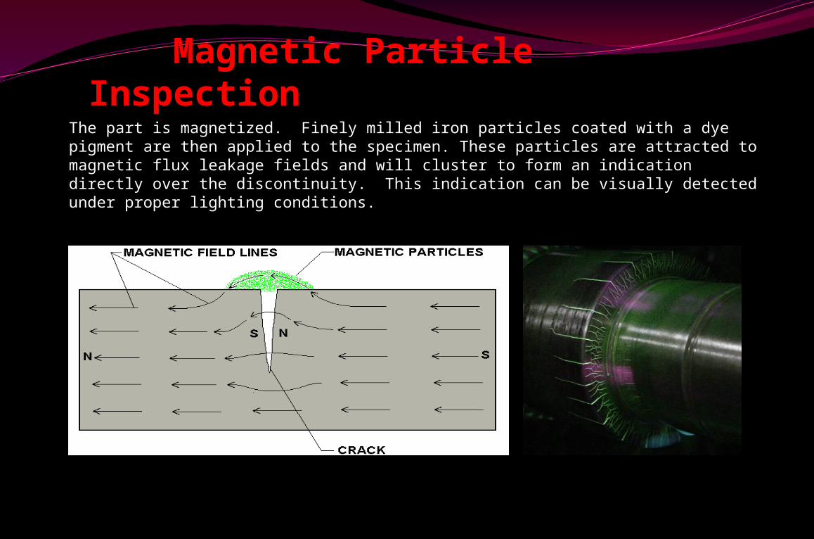
Magnetic Particle Inspection
The part is magnetized. Finely milled iron particles coated with a dye pigment are then applied to the specimen. These particles are attracted to magnetic flux leakage fields and will cluster to form an indication directly over the discontinuity. This indication can be visually detected under proper lighting conditions.
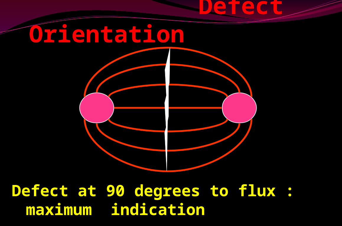
Defect Orientation
Defect at 90 degrees to flux :maximum indication
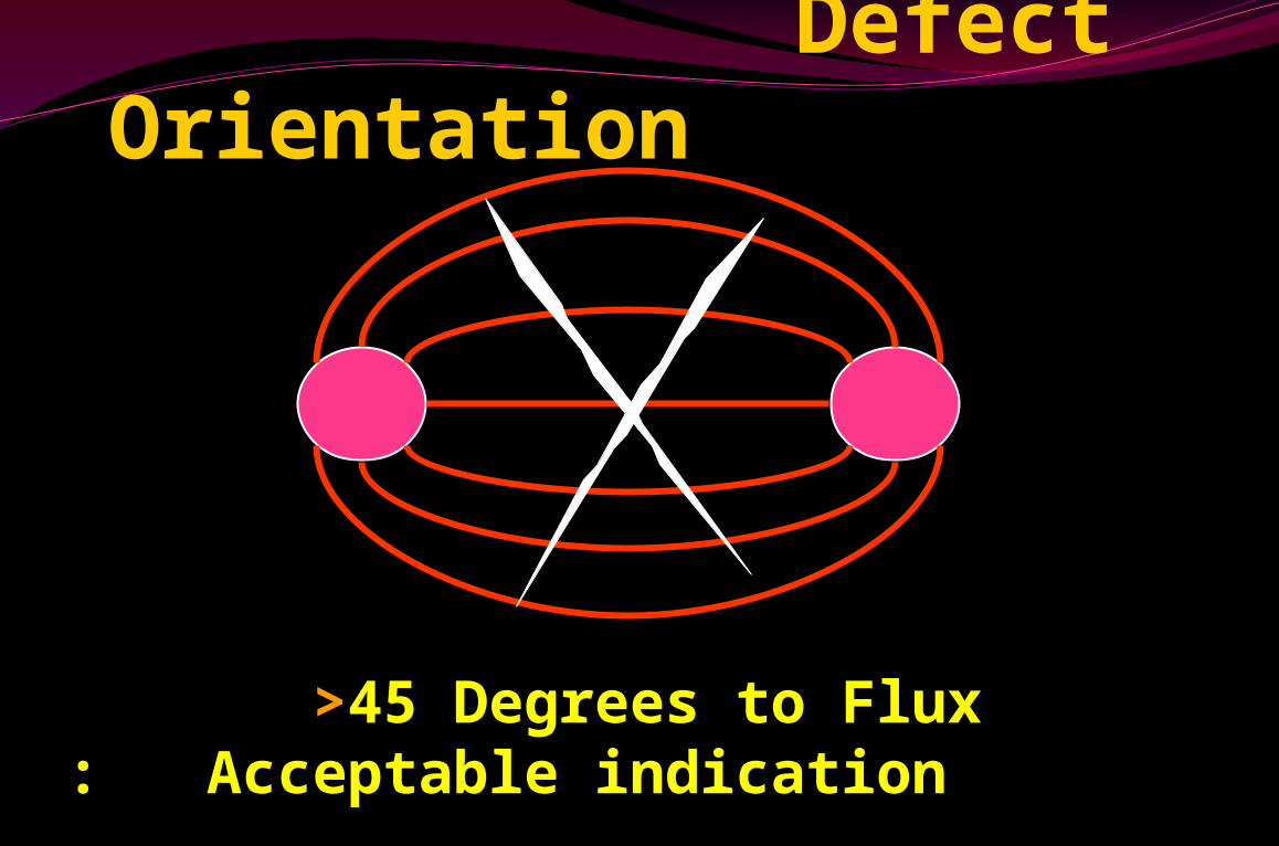
Defect Orientation
>45 Degrees to Flux : Acceptable indication
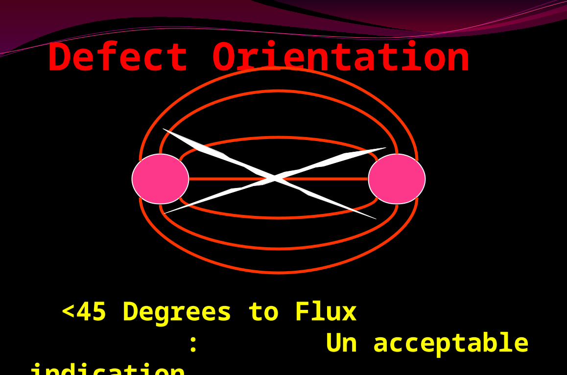
Defect Orientation
<45 Degrees to Flux : Un acceptable indication
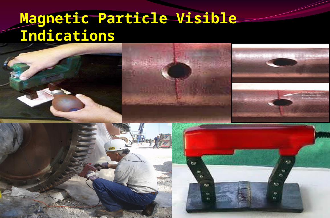
Magnetic Particle Visible Indications

Magnetic Particle Fluorescent Indications
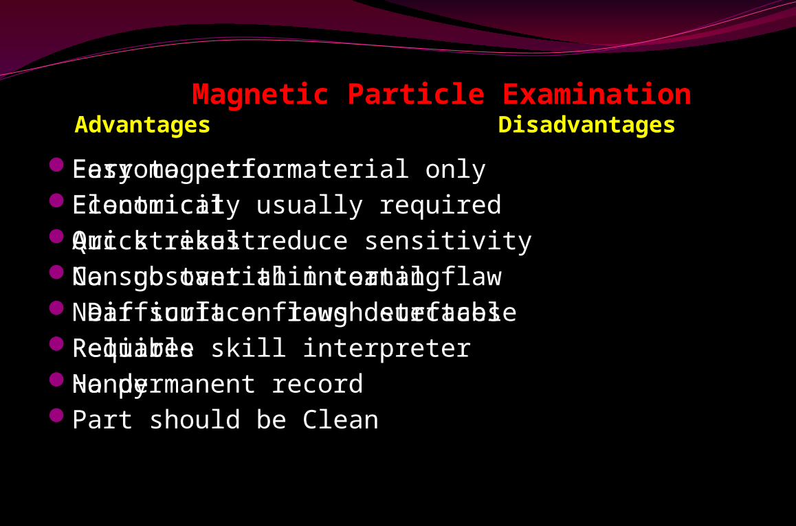
Magnetic Particle Examination Advantages Disadvantages
Easy to performEconomical Quick resultCan go over thin coatingNear surface flaws detectableReliable Handy
Ferromagnetic material onlyElectricity usually requiredArc strikes reduce sensitivityNo substantial internal flaw Difficult on rough surfacesRequires skill interpreterNo permanent recordPart should be Clean
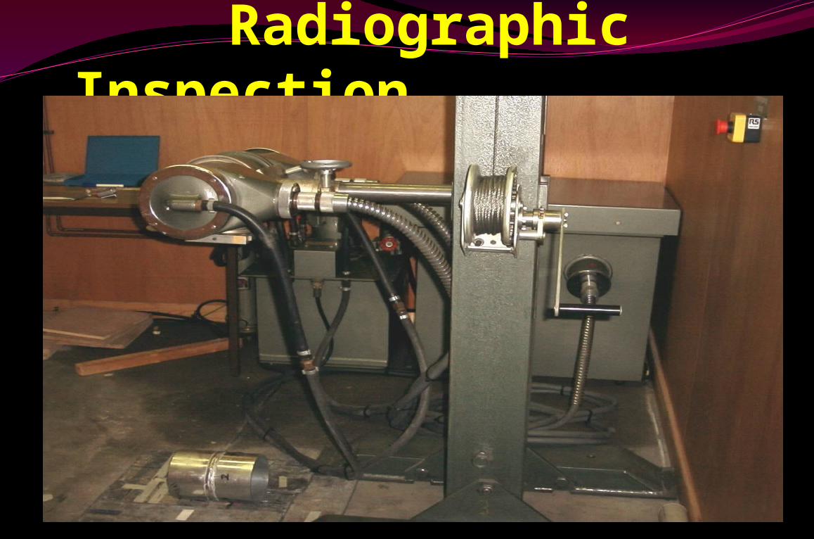
Radiographic Inspection
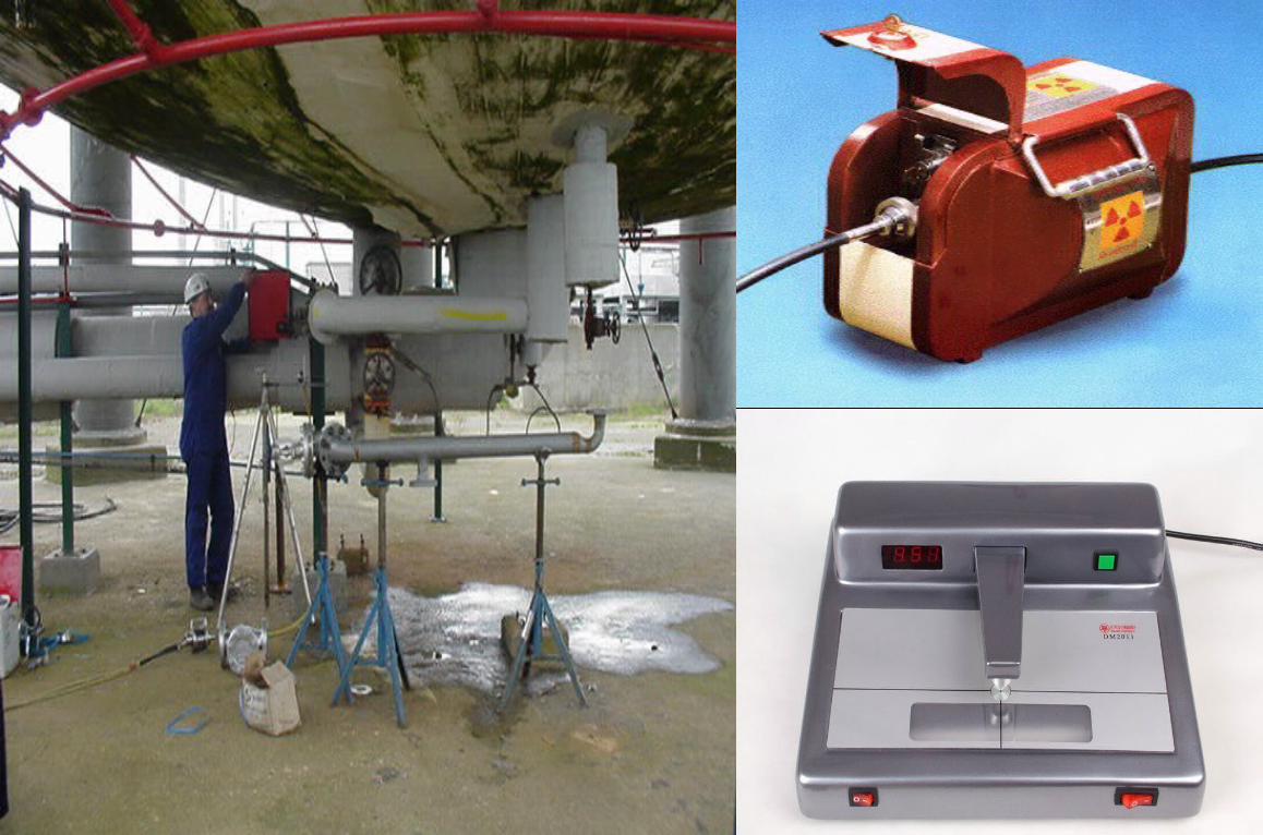
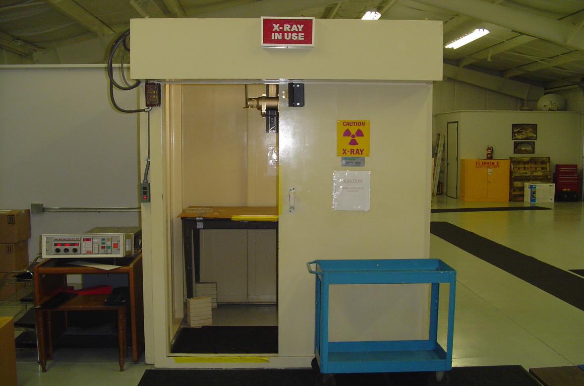
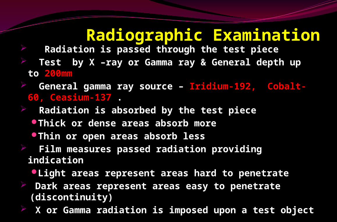
Radiographic Examination Radiation is passed through the test piece Test by X –ray or Gamma ray & General depth up to
200mm General gamma ray source – Iridium-192, Cobalt-
60, Ceasium-137 . Radiation is absorbed by the test piece
Thick or dense areas absorb moreThin or open areas absorb less
Film measures passed radiation providing indicationLight areas represent areas hard to penetrate
Dark areas represent areas easy to penetrate (discontinuity)
X or Gamma radiation is imposed upon a test object
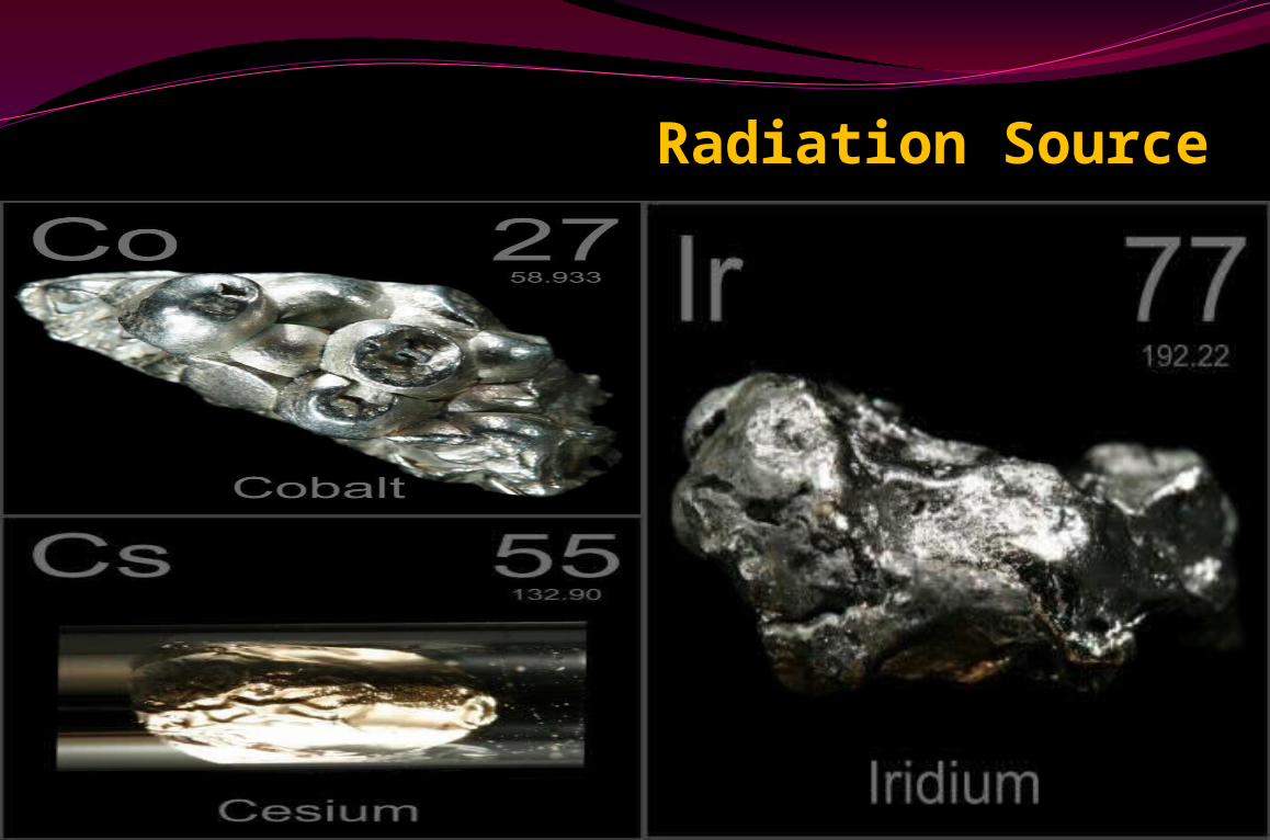
Radiation Source
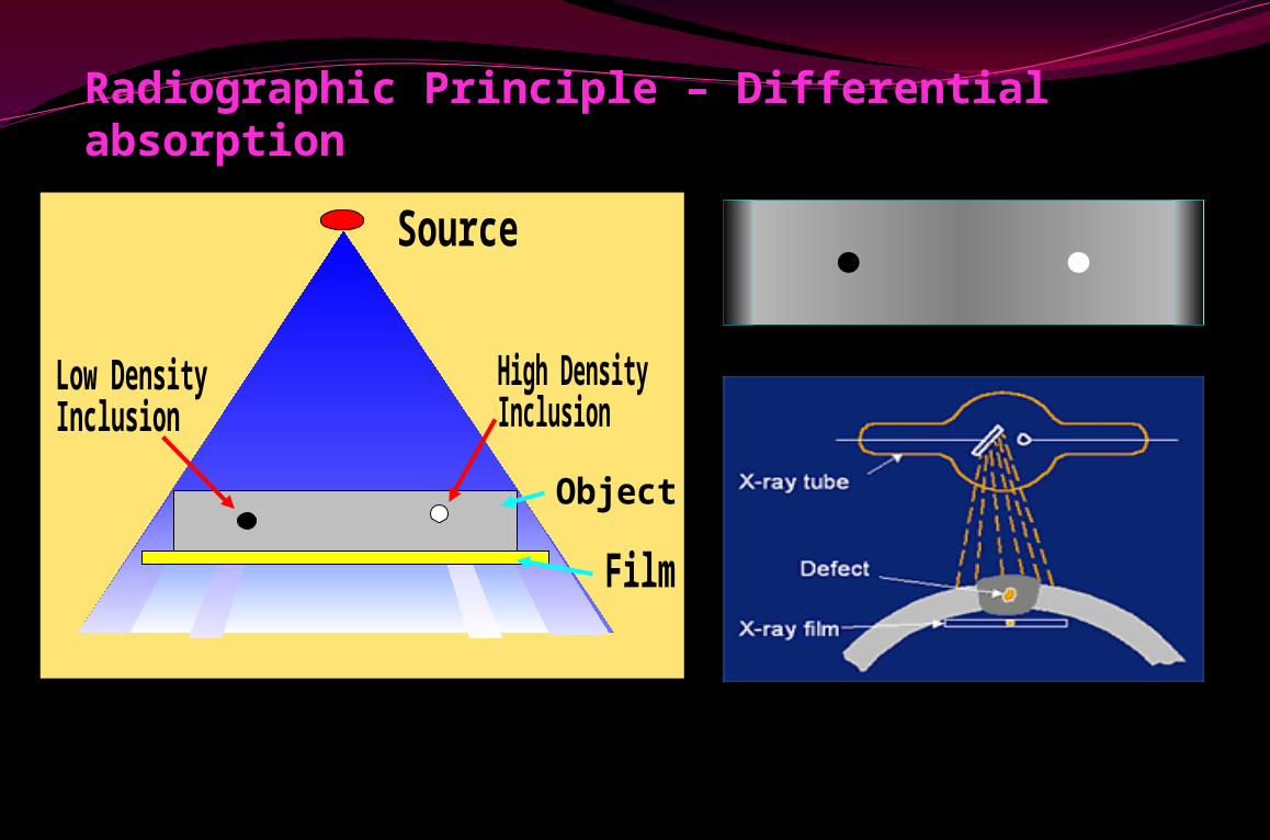
Radiographic Principle – Differential absorption
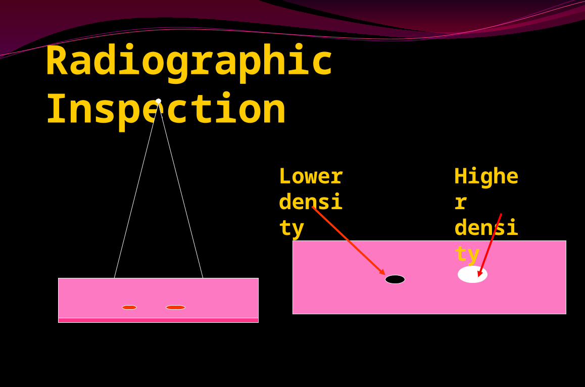
Radiographic Inspection
Lower density
Higher density
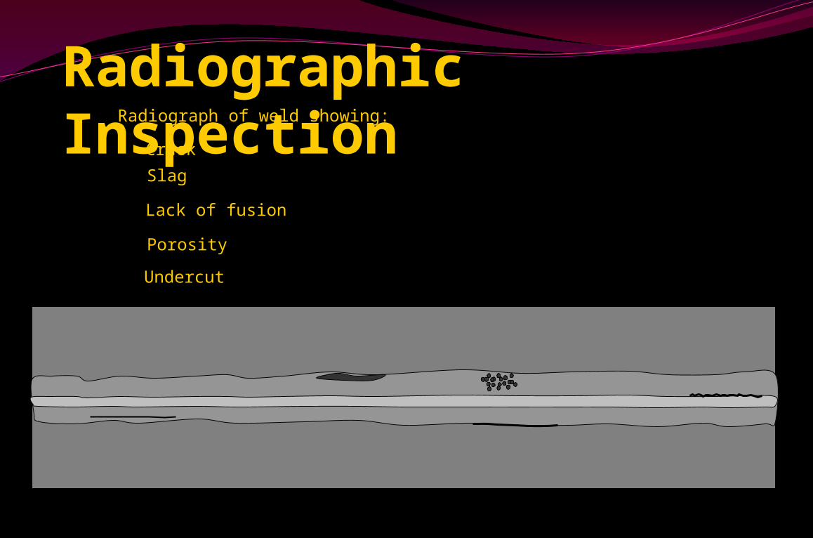
Radiograph of weld showing:
Crack
Slag
Lack of fusion
Porosity
Undercut
Radiographic Inspection
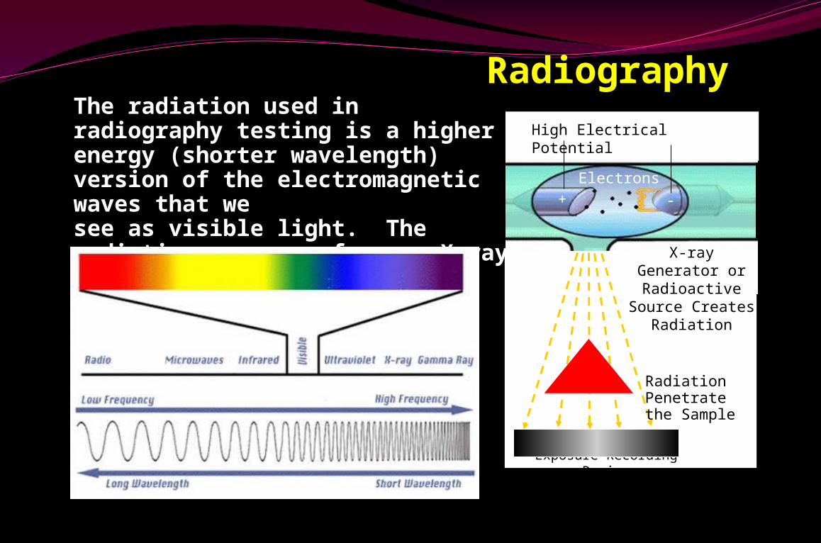
RadiographyThe radiation used in radiography testing is a higher energy (shorter wavelength) version of the electromagnetic waves that we see as visible light. The radiation can come from an X-ray generator or a radioactive source.
High Electrical Potential
Electrons
-+
X-ray Generator or Radioactive Source Creates
Radiation
Exposure Recording Device
Radiation Penetrate the Sample
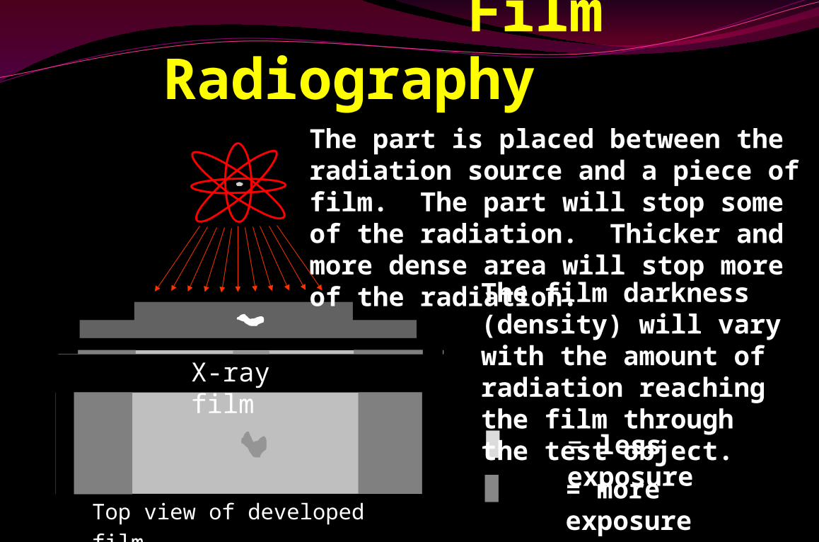
Film Radiography
Top view of developed film
X-ray film
The part is placed between the radiation source and a piece of film. The part will stop some of the radiation. Thicker and more dense area will stop more of the radiation.
= more exposure
= less exposure
The film darkness (density) will vary with the amount of radiation reaching the film through the test object.
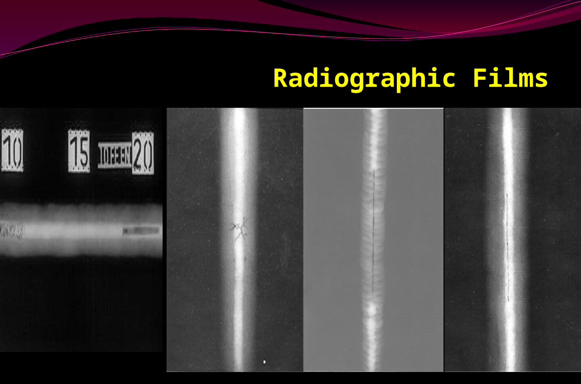
Radiographic Films
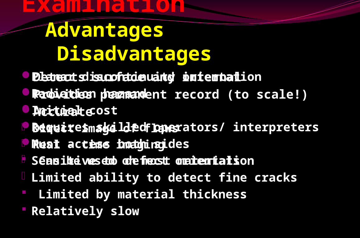
Radiographic Examination Advantages DisadvantagesDetects surface and internalProvides permanent record (to scale!)Accurate• Direct image of flaws• Real - time imaging Can be used on most materials
Planar discontinuity orientationRadiation hazardInitial costRequires skilled operators/ interpretersMust access both sides• Sensitive to defect orientation• Limited ability to detect fine cracks Limited by material thickness Relatively slow
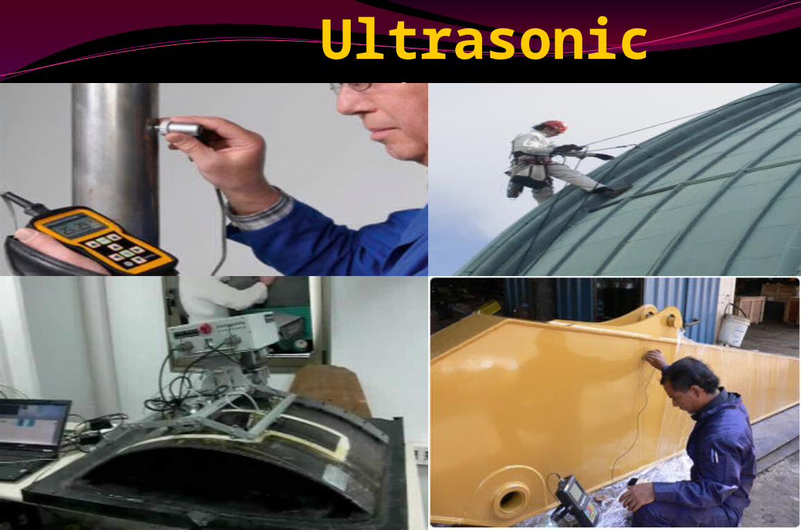
Ultrasonic Inspection
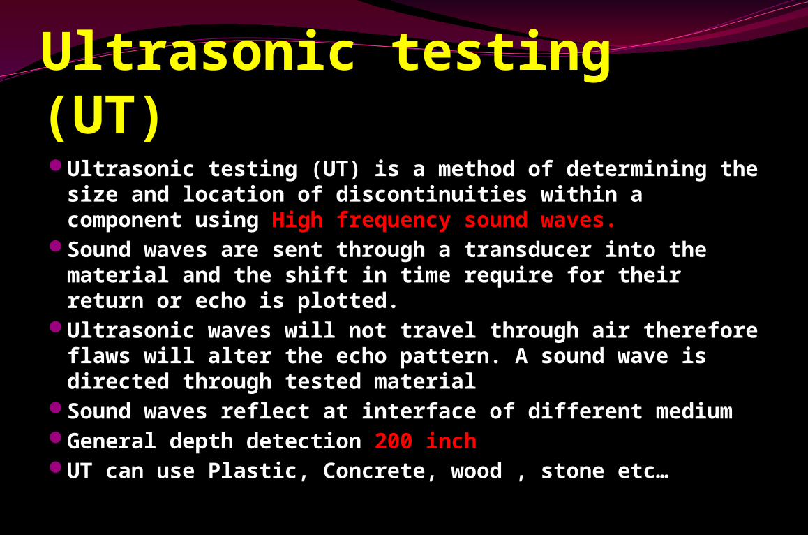
Ultrasonic testing (UT)Ultrasonic testing (UT) is a method of determining the
size and location of discontinuities within a component using High frequency sound waves.
Sound waves are sent through a transducer into the material and the shift in time require for their return or echo is plotted.
Ultrasonic waves will not travel through air therefore flaws will alter the echo pattern. A sound wave is directed through tested material
Sound waves reflect at interface of different mediumGeneral depth detection 200 inchUT can use Plastic, Concrete, wood , stone etc…
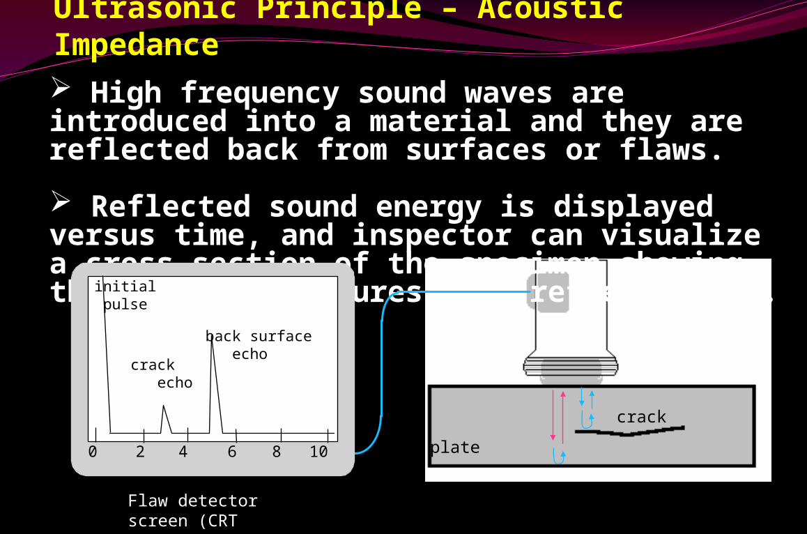
High frequency sound waves are introduced into a material and they are reflected back from surfaces or flaws.
Reflected sound energy is displayed versus time, and inspector can visualize a cross section of the specimen showing the depth of features that reflect sound.
f
plate
crack
0 2 4 6 8 10
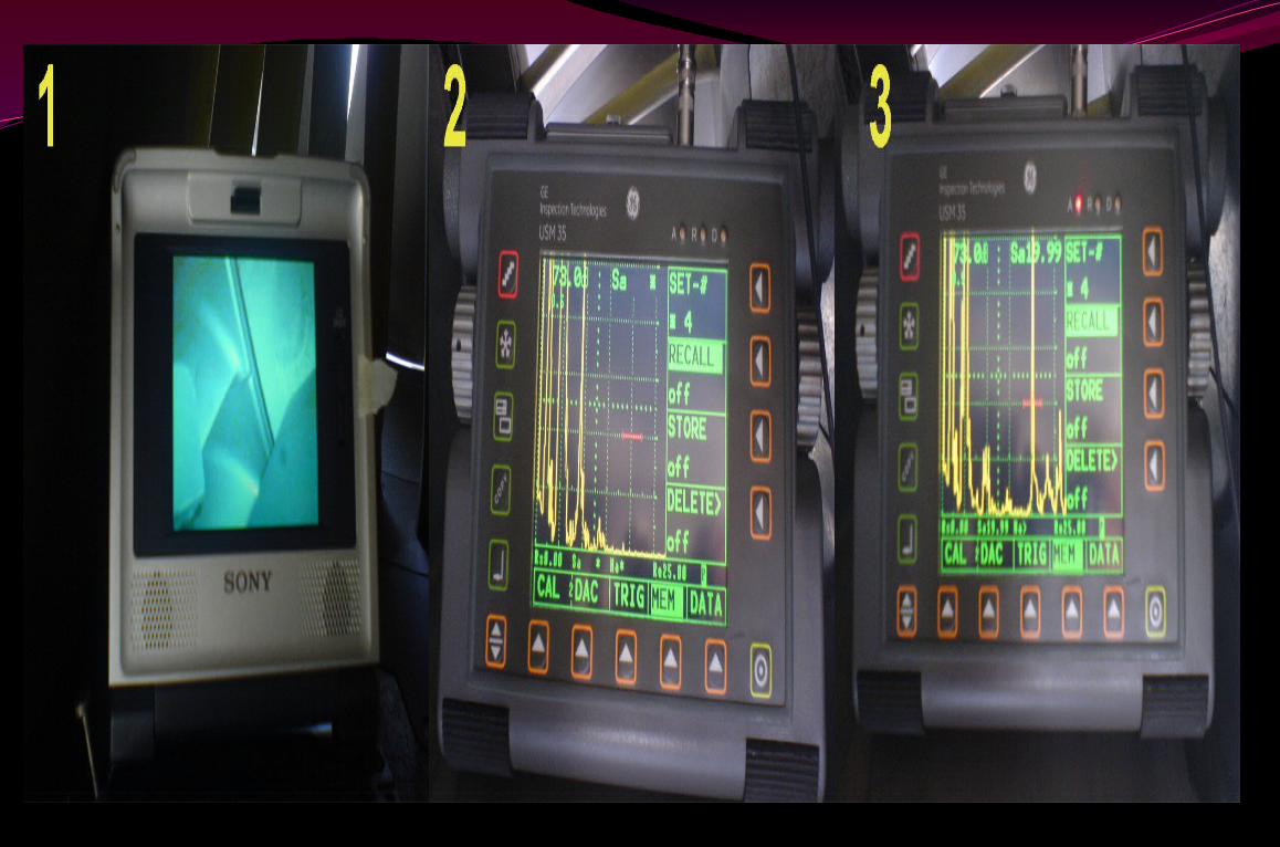
initial pulse
crack echo
back surface echo
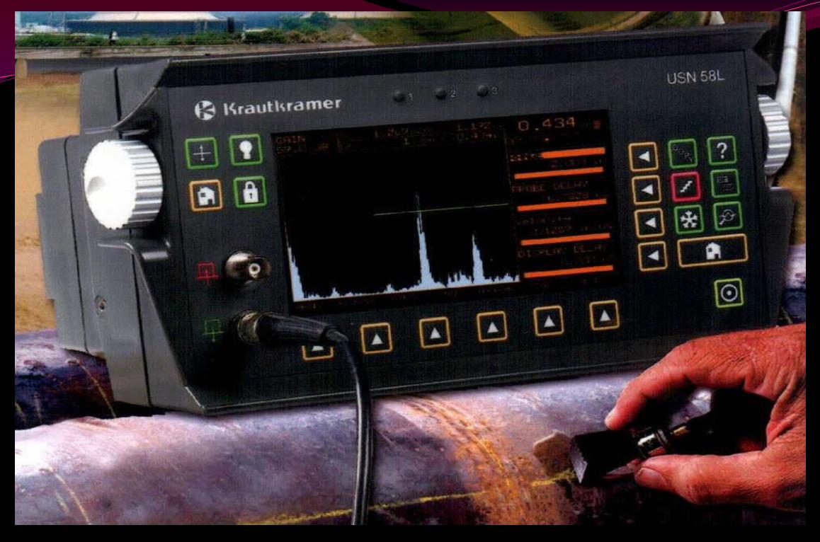
Flaw detector screen (CRT screen)
Ultrasonic Principle – Acoustic Impedance
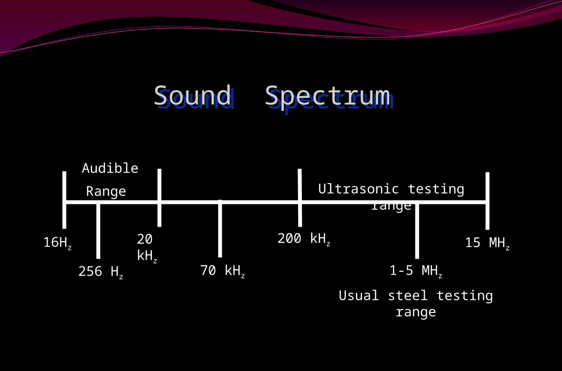
16Hz20 kHz 200 kHz 15 MHz
256 Hz 70 kHz
Audible
Range Ultrasonic testing range
1-5 MHz
Usual steel testing range
Sound SpectrumSound Spectrum
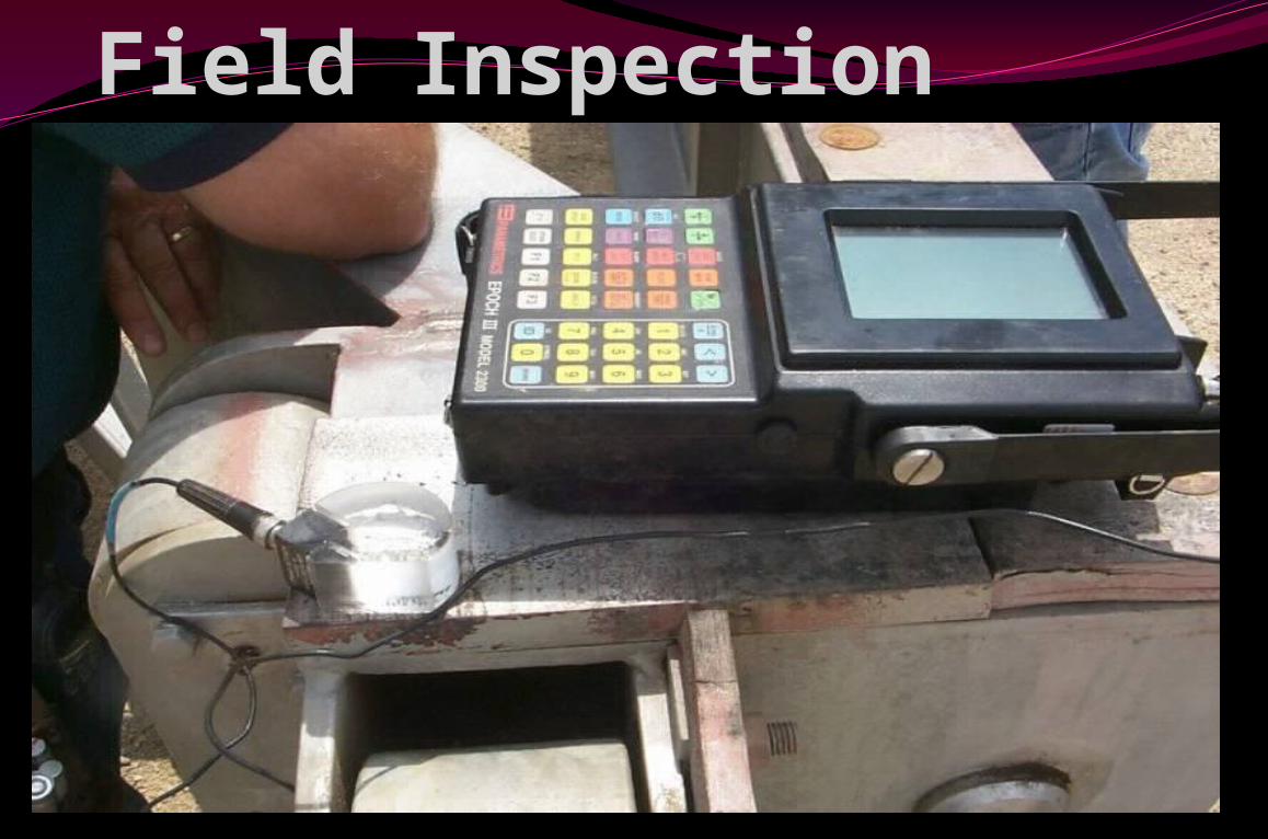
UT Field Inspection
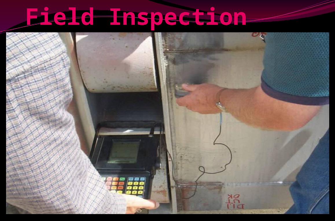
UT Field Inspection
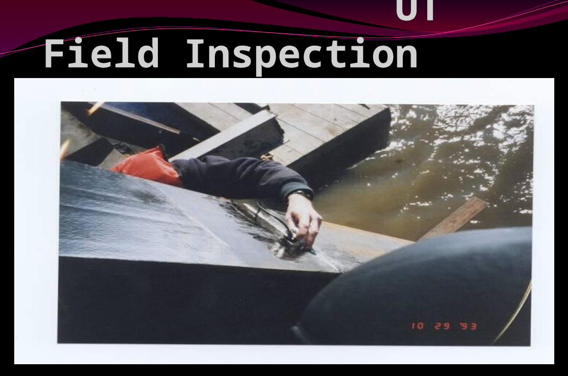
UT Field Inspection
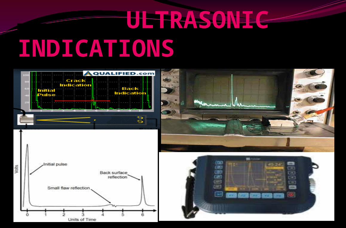
ULTRASONIC INDICATIONS
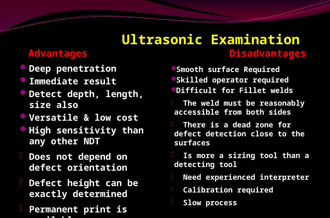
Ultrasonic Examination Advantages DisadvantagesDeep penetrationImmediate resultDetect depth, length,
size alsoVersatile & low costHigh sensitivity than any
other NDT
• Does not depend on defect orientation
• Defect height can be exactly determined
• Permanent print is available
• Lamination detect only by UT
Smooth surface RequiredSkilled operator requiredDifficult for Fillet welds
• The weld must be reasonably accessible from both sides
• There is a dead zone for defect detection close to the surfaces
• Is more a sizing tool than a detecting tool
• Need experienced interpreter
• Calibration required
• Slow process