Embed Size (px)
Citation preview

Aalto UniversitySchool of Science and TechnologyDegree Programme of Computer Science and Engineering
Özgen Akman
Near Field Communication Applications
Master's ThesisEspoo, August 30, 2015
Supervisor: Professor Tuomas Aura, Aalto UniversityInstructor: Professor Tuomas Aura
Aalto UniversitySchool of Science and TechnologyDegree Programme of Computer Science and Engineering
ABSTRACT OF MASTER’S THESIS
Author: Özgen Akman
Title of thesis: Near Field Communication Applications
Date: August 30, 2015 Pages: vii+93
Professorship: Data Communication Software Code: T-110
Supervisor: Professor Tuomas Aura
Instructor: Professor Tuomas Aura
Near Field Communication (NFC) is a short-range, low power contactless communication between NFC-enabled devices that are held in the closed proximity to each other. NFC technology has been moving rapidly from its initial application areas of mobile payment services and contactless ticketing to the diversity of new areas. Three specific NFC tags highlighted in the thesis have different structures in terms of memory, security and usage in different applications. NFC information tags exploit the data exchange format NDEF standardized by NFC Forum.
NFC applications are rapidly stepping into novel and diverse application areas. Often they are deployed in combination with different devices and systems through their integrability and adaptability features.
The diverse application areas where NFC tags and cards are used cover smart posters, contactless ticketing, keys and access control, library services, entertainment services, social network services, education, location based services, work force and retail management and healthcare.
In designing different NFC applications, it is necessary to take into consideration different design issues such as to choosing the NFC tools and devices according to the technical requirements of the application, considering especially the memory, security and price factors as well as their relation to the purpose and usage of the final product. The security aspect of the NFC tags is remarkably important in selecting the proper NFC device. The race between hackers attacking and breaking the security systems of programmable high level products and manufacturers to produce reliable secure systems and products seems to never end. This has proven to be case, for example, for trying MIFARE Ultralight and DESFire MF3ICD40 tags.
An important consideration of studying the different applications of NFC tags and cards during the thesis work was to understand the ubiquitous character of NFC technology.
Keywords: nfc, ndef, mifare ultralight, mifare ultralight c, mifare desfire ev1, smart card, smart poster, applications of nfc tags and cards
Language: English
i
Aalto-yliopisto Perustieteiden korkeakoulu Tietotekniikan tutkinto-ohjelma
DIPLOMITYÖN TIIVISTELMÄ
Tekijä: Özgen AkmanTyön nimi: Near Field Communication Applications
Päiväys: 30. Elokuuta 2015 Sivumäärä: vii+93
Professuuri: Tietoliikenneohjelmistot Koodi: T-110
Valvoja: Professori Tuomas Aura
Ohjaaja: Professori Tuomas Aura
Lähitunnistus yhteys tekniikka (NFC) on lyhyen tähtäimen, pienitehoinen, kontaktiton yhteydenpito NFC yhteensopivien laitteiden välillä, jossa laitteet pidetään toistensä välittömässä läheisyydessä tiedon siirtämiseksi niiden välillä. NFC-teknologia on siirtynyt nopeasti sen alkuperäisiltä toimialueilta eli mobiili maksupalvelujen ja kontaktittomien lippujen sovellusalueilta moninaisille uusille alueille. Kolmella NFC tagillä, joita on käsitelty tässä tutkielmassa, on muistin, turvallisuuden ja käytön kannalta erilaisiä rakenteita, joita käytetään eri sovelluksissa. NFC-tagit käyttävät tiedonvälityksessä NFC Forumin standardoimaa NDEF- tiedonvaihtoformaattia.
NFC sovellukset esiintyvät yhä enenevässä määrin nopeasti kehyttyvillä, uudenlaisilla ja monipuolisilla sovellusalueilla, usein yhdessä eri laitteiden ja järjestelmien kanssa. NFC on käytettävissä erinäisten laitteiden kanssa erilaisissa järjestelmäympäristöissä. Monipuoliset sovellusalueet, joissa muun muassa NFC-tagejä ja -kortteja käytetään sisältävät seuraavanlaisia sovelluksia: älykkäät julisteet, kontaktittomat liput, avaimet ja pääsynvalvonta, kirjastopalvelut, viihdepalvelut, sosiaalisen verkoston palvelut, kasvatukseen ja koulutukseen liittyvät palvelut, sijaintiperustaiset palvelut, työvoiman ja vähittäiskaupan hallinto-palvelut ja terveyspalvelut.
Erilaisten NFC-sovelluksien suunnittelussa on väistämätöntä ottaa erilaisia suunnitteluasioita huomioon kuten valita NFC-työkalut ja laitteet sovelluksen teknisten vaatimusten mukaan. Erilaiset tärkeät tekijät kuten muisti, tietoturvallisuusominaisuudet ja hinta ja niiden kaikkien toimivuus lopputuotteen kannalta on otettava huomioon. Tietoturvallisuusnäkökohta on erityisen tärkeä oikean NFC laitteen valitsemisessa, sillä käynnissä on loputon kilpajuoksu hakkerien, jotka yrittävät rikkoa ohjelmoitavien korkeatasoisten laitteiden ja tuotteiden tietoturvajärjestelmiä, ja valmistajien, jotka pyrkivät tuottamaan luotettavia varmoja järjestelmiä, välillä. Tietoturvariskiin liittyviä ongelmia on löydetty esimerkiksi MIFARE Ultralight ja DESFire MF3ICD40 tageista.
Tärkeä havainto, joka saatiin erilaisten NFC sovelluksien tutkimisesta, oli oivaltaa NFC- teknologian potentiaalinen kaikkialle ulottuva, yleiskäyttöinen luonne.
Asiasanat: nfc, ndef, mifare ultralight, mifare ultralight c, mifare desfire ev1, smart card, smart poster, applications of nfc tags and cardsKieli: englanti
ii

Acknowledgements
I am grateful to my supervisor and instructor Professor Tuomas Aura for his support, guidance, feedbacks, discussions, enthusiasm and comments on my thesis.
I would like to thank to my friend Eero Hämäläinen for his generous help through discussions, valuable comments, tips and advices. I would also like to thank to my wonderful children, to my son Ata Akman and to my daughter Sevi Akman for being the main inspiration of my everyday life and for their love, support and understanding. Last but not least, I want to thank especially to my sister Fügen Akman for her love, support, caring, patience and encouragement.
In memory of my parents, my father İbrahim Akman and my mother Zeynep Akman. Thank you so much that you have always supported my dreams and ambitions, moreover for your unconditional, endless love...
Espoo, August 30, 2015
Özgen Akman
iii

Abbreviations and Acronyms
AC Alternating Current
AID Application Identifier
APDU Application Protocol Data Unit
CBC-MAC Cipher-Block Chaining MAC
CC Capability Container
CICC Close-coupled Integrated Circuit Card
CMAC Cipher-based MAC
DES Data Encryption Standard
FID File Identifier
IANA Internet Assigned Numbers Authority
IV Initialization Vector
2K3DES Triple DES, keying option 2 (K1 ≠ K 2 K1 = K3)∧3K3DES Triple DES, keying option 1 (K1 ≠ K2 ≠ K3)
lsb least significant bit
LSB Least Significant Byte
MAC Message Authentication Code
MF0ICU2 MIFARE Ultralight C
MF3ICD40 MIFARE DESFire (predecessor of MF3ICD41)
MF3ICD41 MIFARE DESFire EV1
msb most significant bit
MSB Most Significant Byte
MULTOS Multi-application operating system
NDEF NFC Data Exchange Format
NFC Near Field Communication
NFC Forum A non-profit industry association that advances the use of near field communication (NFC) technology
iv

OTP One-Time Programmable
PCD Proximity Coupling Device
PICC Proximity Integrated Circuit Card
POS Point of Sale
RF Radio Frequency
RFU Reserved for Future Use
SCOS Smart card operating systems
Triple DES Triple Data Encryption Algorithm (TDEA)
UID Unique Identifier
VICC Vicinity Integrated Circuit Card
v

Contents
Acknowledgements.............................................................................................................................iiiAbbreviations and Acronyms.............................................................................................................ivChapter 1.............................................................................................................................................1Introduction..........................................................................................................................................1
1.1 Problem statement......................................................................................................................21.2 Methodology..............................................................................................................................21.3 Structure of the thesis................................................................................................................2
Chapter 2.............................................................................................................................................4Background and related work...............................................................................................................4
2.1 Near field communication.........................................................................................................42.1.2 Operation and communication modes................................................................................42.1.3 Standards............................................................................................................................52.1.4 Security..............................................................................................................................6
2.2 Smart cards................................................................................................................................72.3 Related projects..........................................................................................................................9
Chapter 3...........................................................................................................................................12MIFARE Contactless Smart Cards.....................................................................................................12
3.1 MIFARE Ultralight Family......................................................................................................123.1.1 Static Memory Structure..................................................................................................133.1.2 Dynamic Memory Structure.............................................................................................143.1.3 Security............................................................................................................................19
3.2 MIFARE Ultralight C..............................................................................................................193.2.1 Memory organization.......................................................................................................203.2.2 Security............................................................................................................................21
3.3 MIFARE DESFire EV1...........................................................................................................223.3.1 Commands.......................................................................................................................233.3.2 File system.......................................................................................................................243.3.3 Security............................................................................................................................25
3.4 NDEF standard........................................................................................................................263.4.1 NDEF Record Layout......................................................................................................29
3.5 NFC Tag Use Cases.................................................................................................................35Chapter 4...........................................................................................................................................38Applications of NFC tags and cards...................................................................................................38
4.1 Smart Posters...........................................................................................................................384.2 Ticketing..................................................................................................................................41
4.2.1 Ticket implementation options.........................................................................................424.3 NFC implementation in keys and access control.....................................................................444.4 NFC implementation in Library services.................................................................................444.5 NFC implementation in entertainment services.......................................................................454.6 NFC implementation in social network services.....................................................................494.7 NFC implementation in educational services..........................................................................574.8 NFC implementation in location based services......................................................................64
vi

4.9 NFC implementation in work force and retail management services......................................684.10 NFC implementation in healthcare........................................................................................71
Chapter 5...........................................................................................................................................76Technical features required by the applications.................................................................................76
5.1 MIFARE Ultralight..................................................................................................................765.2 MIFARE Ultralight C..............................................................................................................765.3 MIFARE DESFire EV1...........................................................................................................77
Chapter 6...........................................................................................................................................79Implementation experiments..............................................................................................................79
6.1 Tools and technologies.............................................................................................................796.2 Programming task and experiments with Mifare Ultralight card............................................80
6.2.1 NDEF messages...............................................................................................................816.2.2 Ticket application with Mifare Ultralight .......................................................................816.2.3 Deficiency in the security of Mifare Ultralight ticket......................................................816.2.4 Simultaneous handling of multiple cards.........................................................................82
6.3 Programming task and experiments with Mifare DESFire EV1 card.....................................826.3.1 Ticket application with Mifare DESFire EV1..................................................................82
Chapter 7...........................................................................................................................................83Discussion of NFC application design issues.....................................................................................83
7.1 NFC tag design and applications.............................................................................................837.2 Other smart cards.....................................................................................................................84
7.2.1 Programmable contactless smart cards and tags..............................................................857.2.2 JavaCards.........................................................................................................................857.2.3 Bank cards........................................................................................................................86
Chapter 8...........................................................................................................................................88Conclusions........................................................................................................................................88Bibliography.......................................................................................................................................90
vii

CHAPTER 1. INTRODUCTION
Chapter 1
IntroductionNear Field Communication (NFC) is a newly emerging and rapidly sprawling technology which wirelessly connects two NFC-enabled devices or an NFC-enabled device and a tag to enable simple and safe two-way interactions among the devices. It is a standards-based, short-range, low power contactless radio connectivity technology that enables communication between devices that either touch or are momently held close together. Examples for the NFC-enabled devices can include NFC-readers, such as reader terminal, a mobile phone, a notebook or Personal Digital Assistant (PDA) or NFC-enabled device acting as an NFC-tag in card emulation mode or as a smart card tag. The focus of this thesis is on the NFC-tags. The intensive usage of the smart card tags in different areas of daily life is already common phenomenon.
NFC is an open-platform technology that is being standardised in the NFC Forum. The NFC Forum is an industry consortium aiming at further developing and improving the Near Field Communication (NFC) technology. The main focus of the consortium is to guarantee interoperability among devices and services. NFC Forum sets the standarts for NFC devices and NFC tags. According to the standards, an NFC Forum Device implements at least the mandatory parts of the NFC Forum protocol stack and complies with the NFC Forum interoperability requirements. An NFC Forum Device may support different NFC Forum operating modes: NFC Forum peer-to-peer mode (mandatory), NFC Forum Reader/Writer mode (mandatory), and NFC Forum card emulation mode (optional) [1]. A contactless NFC Forum Tag is compatible with and can operate according to one of four NFC Forum Tag Platforms called NFC Forum Type 1-4 Tag Platforms, the NFC Type MIFARE Classic Tag Platform and NFC Type ICODE Tag Platform or a Target according to ISO/IEC 18092 [2]. The main focus of the thesis is on the NFC Forum Type 2 Tag and NFC Forum Type 4 Tag v2.0 Platforms.
The solutions proposed by this thesis aim to exploit and investigate the benefits of the NFC-tag applications from the perspective of the NFC Forum Type 2 Tag and NFC Forum Type 4 Tag platforms.
1

CHAPTER 1. INTRODUCTION
1.1 Problem statementNFC is a new, fast developing and spreading technology interacting with the automation ubiquitously around us. The technology exploits the benefits of wireless communications, mobile devices, mobile applications and smart cards. NFC devices are classified in the communication as active devices, which are powered by some power source such as alternating current (AC) or a battery and which also initiate the communication. Active devices can be both initiators and target of the NFC communication. Passive devices have no integrated power source. They are also called target devices. An active device powers the passive device by creating the electromagnetic field.
A NFC-tag is a passive device without any available power sources which responds to the initiator’s requests in the NFC communication.
NFC-tags in the form of smart cards are valuable assets that people carefully carry with and already extensively used items of the daily life. They can store critical information concerning user's private and personal information for instance in terms of loyalty, credit, debit and travel cards, tickets for entertainment events as well as for tracking and monitoring persons and objects, aiming at allowing authorized access to that information.
This work intends to explore the benefits of the efficient use of the NFC-tag applications by researching the functionalities of the applications.
1.2 MethodologyThe purpose of this work is to study, define requirements and provide software implementation for NFC-tags in Near Field Communication technology in the form of travel and event tickets implementation.
In order to reach the solution, it is important to understand NFC technology and comprehend the properties and functionalities of NFC-tags.
Understanding of NFC technology and the properties and functionality of NFC-tags will create the necessary bases to find the reasonable solution to the problem. The next step will be to evaluate the provided solution against the requirements previously set.
The following steps are included in the process:
• Background. What needs to be studied and understood when developing NFC software?
• Requirements. What are the requirements for the NFC application software?
• Design. How should the NFC application software be designed to most efficiently meet the requirements? What tools and technologies should be used?
• Implementation and testing. The actual implementation and testing of the software.
• Verification. How could the software be verified to make sure that the requirements are met?
1.3 Structure of the thesisChapter 1 presents the introduction and provides some background information and motivation for the subject, defines the purpose of the study and describes the structure of the thesis. Chapter 2 provides theoretical background information for the concepts and requirements that are used in the
2

CHAPTER 1. INTRODUCTION
implementation phase. It also explains the motivations for the solutions. Chapter 3 provides a comprehensive study of the NFC Forum Tag Platforms Type 2 MIFARE Ultralight, Ultralight C, and Type 4 DESFire and and also explains the NDEF standard.
Chapter 4 discusses the diversity of NFC applications in detail, Chapter 5 details the technical features of NFC tags and cards required by the NFC applications, and Chapter 6 describes the programming work of the thesis and implementation experiments, Chapter 7 discusses the NFC application design issues. Finally, Chapter 8 summarizes the work done and discusses the meaning of the study and concludes the thesis.
3

CHAPTER 2. TEORETICAL BACKGROUND
Chapter 2The chapter begins with the general information about the NFC technology and its devices. Short description of operation and communication modes is followed by standards. An important issue of security in NFC is also discussed. Chapter proceeds with the perspective of broader smart cards selection. The last section of the chapter is related to the projects in NFC technology.
Background and related workOne of the obvious recent phenomenons has been the expansion of ubiquitous computing into humans' lifes where computing devices are almost completely integrated into everyday life and the objects around, and are simple to use. Rise of near field communication is one of the consequences of ubiquitous computing. The way NFC works is intuitive. The communication takes places when the two NFC enabled devices, for instance, such as a NFC reader and a NFC tag are in close proximity. Reader device creates an electromagnetic field which in turn powers the smart card. The smart card can then respond to the request of the reader. Contactless smart cards interact intelligently with an external device. Close proximity connectivity demand of contactless smart cards make them elegible to be used in applications that need a high level of security to protect sensitive information and perform secure transactions. A contactless smart card includes a secure micro controller and internal memory. This let the smart card to perform complex functions such as encryption or other security functions and securely manage, store and provide access to data on the card. Applications that require a high level of security such as payment applications, personal IDs or electronic passports use contactless smart card technology. The working distance of approximately up to 10 cm ensures for the applications using contactless smart cards, data integrity and confidentiality, and privacy of information stored or transferred. The focus of the thesis is on this kind of mechanism of smart card technology.
Near field communication technology is introduced next, followed by the smart cards NFC tag types MIFARE Ultralight, MIFARE Ultralight C, MIFARE DESFire. NDEF standard is also introduced. The last section presents the related work.
2.1 Near field communicationNear field communication (NFC) is a short-range (4 to 10 cm) wireless communication technology that enables communication between two NFC compliant devices. It is based on the RFID technology and operates on 13.56 Mhz frequency. The NFC standard supports different data transmission rates such as 106 kBps, 212 kBps and 424 kBps.
2.1.2 Operation and communication modes
There are two major modes of communication in NFC. The first one is initiator and target device communication, the other one is active and passive device communication.
4

CHAPTER 2. TEORETICAL BACKGROUND
The NFC device that starts the communication is the initiator and the device which responds to the request is the target. The target device can be another NFC device, a contactless smart card or a NFC tag.
In active communication mode, both the initiator and the target generate their own electromagnetic field to exchange data. In this case target component of the communication deactivates its own electromagnetic field to receive data from the initiator. Whereas in passive communication mode, only the initiator device generates an electromagnetic field and the target uses load modulation to transfer data.
The focus of this work is on the initiator-target NFC communication mode, where the initiator is a NFC active device with an integrated power source and the target is a contactless smart card or a NFC tag with no integrated power source.
NFC devices can operate in three different modes based on the ISO/IEC 18092, NFC IP-1, and ISO/IEC 14443 contactless smart card standards [4].
These operation modes are reader/writer mode, peer-to-peer mode and card emulation mode. In reader/writer mode, NFC enabled device initiates the communication and either reads or writes data from or to those passive targets. The passive target in this case is either contactless smart card, an NFC tag or an NFC device in card emulation mode. In peer-to-peer mode, both NFC devices are in active mode during the communication and establish a bidirectional half duplex communication channel to exchange data. This means that when the initiator device is transmitting data, the target device listens and target starts to transmit data only after initiator device finishes. In card emulation mode NFC enabled device presents itself as a passive target and does not generate its own electromagnetic field.
2.1.3 Standards
Standardisation in maintaining the interoperability and compatibilty of NFC devices and protocols is an important aspect in NFC technology. NFC uses standardised proximity range communication interfaces which differ in data transmission features of the RF layer. RF layer of NFC is above the standard protocols and it is compatible with different standards. Some relevant standars operating at 13.56 Mhz are ISO/IEC 18092 standard which defines device-to-device communication for both active and passive communication modes with the proximity range and 106, 212 and 424 kbps data transmission rates. The standard especially defines transport protocol along with the protocol activation, data exchange protocol, error detecting code calculation and protocol deactivation. ISO/IEC 14443 standard is a contactless proximity smart card standard defining reader-to-card communication for passive communication mode with the proximity range and 106 kBps data transmission rate. ISO/IEC 14443 is composed of four major parts which define the physical characteristics of the card, radio frequency power and signal interface between proximity coupling device and proximity integrated circuit card, along with initialization, anticollision and transmission protocols, as well as the optional type A and type B contactless cards. ISO/IEC 15693 standard is a contactless vicinity smart card standard defining reader-to-card communication for passive communication mode with the vicinity range and up to 26 kBps data transmission rate.
Some of the prominent proximity coupling smart card technologies that are compatible with ISO/IEC 14443 are MIFARE, Calypso and FeliCa.
MIFARE is popular 13.56 Mhz contactless proximity smart card developed and owned by NXP semiconductors that is a spin-off company of Philips Semiconductors. It is ISO/IEC 14443 Type A standard. The family of MIFARE contains the types Ultralight, Standard, Desfire, Classic which
5

CHAPTER 2. TEORETICAL BACKGROUND
have varying memory sizes, Plus and SmartMX. MIFARE smart cards are very widely used in different applications such as public transport ticketing, access management and e-payment.
FeliCa is a 13.56 contacless proximity smart card from the Japanese company Sony. FeliCa complies only with Japanese Industrial Standard (JIS) X 6319 Part 4 which defines high speed proximity cards. It is used mainly in electronic money cards.
Calypso is also a 13.56 contacless proximity smart card used in public transportation. It was designed by an European transit operators from Belgium, Germany, France, Italy and Portugal. The ISO/IEC 14443 Type B standard and the European satandard EN 1545 defining the ticketing data for smart cards are results of this work.
ISO/IEC 21481 standard defines the communication mode selection mechanism which does not interfere with any ongoing communication at 13.56 Mhz for devices implementing ISO/IEC 18092 , ISO/IEC 14443 (e.g. MIFARE) or ISO/IEC 15693 (e.g. Long range vicinity communication, RFID tags).
Another important and relevant standart is NFC Data Exchange Format (NDEF) [5] which is defined by the NFC Forum. NDEF is a data format to exchange information between either two active NFC devices or between an active NFC device and a passive NFC tag. The NFC Data Exchange Format specification defines the data structure format to exchange application specific data in an interoperable way.
NFC Forum also specified another very important and relevant standards for NFC Forum Mandated Tag Types. The standard defines four tag types which are compatible and operable with NFC devices [6-9]. Each of the tag types differ in memory size and organization, security properties and transmission protocol. NFC Type 1 and type 2 tags are based on ISO/IEC 14443 Type A standard. They are both readable and writable and the data on these tags may be modified to be configured as raed-only when required. Memory availability on type 1 tag is 96 bytes and on type 2 tag is 64 bytes. Available memories of both tags can be expandable to 2KB. The communication speeds of both tags are 106 kBps. NFC Type 3 tag is based on the Sony FeliCa contactless smart card standard of (JIS) X 6319 Part 4. The current memory availability of this tag is 2 kB and data communication speed is 212 kBps. NFC Type 4 tag is compatible with both ISO/IEC 14443 Type A and Type B standards. The type of these tags is defined during the manufacturing phase and tags are also pre-configured as either writable or read-only. Memory availability of Type 4 tag is 32 kB and the communication speed is between 106 and 424 kBps.
2.1.4 Security
All the information systems including NFC based systems are subject to attacks that threaten system security and user privacy. There is always a struggle between the hackers and the security providers. While security providers are aiming at creating security mechanisms to enable a strong degree of protection and enough level of functionality, hackers aim to pass over these mechanisms. As the different NFC operating modes use different communication protocols, some security threats are similar whereas some issues are unique for each operating mode. The components of the different NFC operating modes from the security perspective can be classified as follows: security concerns related to the NFC tag, security concerns related to the NFC reader, security concerns related to a smart card, security concerns related to communication, security concerns related to middleware and backend systems and standardized security protocols.This section illustrates briefly some possible attacks to NFC tags.
Attacks on NFC tags:
6

CHAPTER 2. TEORETICAL BACKGROUND
Tag cloning. Tag cloning means creating exact copy of a valid tag. Aim of cloning the tag is to reuse the content of the tag mutiple times.
Tag content changes. This means modifying the tag to change its content. This also may lead to several more attacks:
• Spoofing attacks. This is the way to provide to the user false information which looks like valid to make the user insert fake domain name, telephone number or false information about the identification of some person, item or activity on to the tag.
• Manipulating tag data. This is the way to change content of the tag for some malicious purpose.
• Denial of Service (DoS) attack. Main aim in this attack is to damage the relationship between the user and the service provider by forcing the system to perform some unnecessary and illegal action.
Tag replacement and tag hiding. In this attack a malicious tag designed to perform illegal actions such as making the system work as the attacker desires may be replaced with the NFC tag or the malicious tag can be sticked on top of the original one.
Attacks on NFC communication:
Eavesdropping. The aim is to record communication between NFC devices by using high-powered antenna.
Data corruption. In addition of recording communication between NFC devices, the aim is to modify the transmitted data.
Data modification. The aim is to modify or delete valuable information by intercepting the communication.
Data insertion. Attacker try to insert data into the exchanged messages between two NFC devices. This can be successful only if this data can be send fast enough before the original device responds. If both data streams overlap, The data will be corrupted.
Man-in-the-middle-attack. Unknown third parties behave like the other party in communication and relay information back and forth.
Relay attack. ISO/IEC 14443 compatible cards are vulnerable to relay attacks. Attacker inserts messages into the exchanged data between two devices.
Replay attack. A valid NFC signal is intercepted and its data is recorded for a later use and transmitted to a reader afterwards. Since the data appear valid the reader accepts it.
2.2 Smart cardsSmart cards are devices which include embedded integrated circuits, a memory unit or microprocessor chip. The motivation for smart cards is the need for efficient, secure data processing and transfer and store portable record of applications which can be updated as well as to store and process personal and private information. Smart cards are used in different areas: authentication, authorization, data storage, identification, banking, retail and transportation. One of the prominent advantages of the smart card sytem is to be able to efficiently process, store and transfer the data in electronic form.
From the capability perspective, smart cards can be devided into memory-based and
7

CHAPTER 2. TEORETICAL BACKGROUND
microprocessor-based smart cards. Memory-based smart cards have no processing capability. To manipulate the data on the card, Memory-based smart cards communicate with an external device using synchronous protocol. Microprocessor based smart cards have microprocessor, memory and smart card operating systems (SCOS). These cards are multi functional and are able to record, modify and process data as well as control the access to information and functions by means of managing security of the card in terms of data integrity. Microprocessor based smart cards may also have a file system which can contain coexisting applications.
SCOS had costly and an inflexible deficiency in its development. An application or service was written for a specific operating system, which forced the card issuer to agree with a specific application developer and operating system. Multi-application operating system (MULTOS) enabled a standard secure SCOS which allowed the implementation of multiple applications on any chip. The applications from different vendors are able to run and operate on the same card independently and securely.
The other multi-application smart card operating system is JavaCard OS. JavaCard enables applications which are known as applets and written in the subset of the Java programming language called JavaCard Language, to run on the same smart card. JavaCard uses the advantages provided by the Java language secure, interoperable and multiapplication platform through the properties of object-oriented programming, reuse of existing development environments, strong typed language, several levels of access control to methods and variables and interoperability. This gives programmers independence over architecture and applications created within this operating system can be run on any vendor of smart cards. The ability to upgrade and update the application on the smart card after delivering the card to the end-user when necessary is another prominent advantage of JavaCard OS. JavaCard Virtual Machine (JCVM) interprets and runs the applications written in Java programming language. JavaCard Virtual Machine (JCVM) executes its task in two parts: part of it runs on the card as the byte code interpreter and the other part runs outside the card as converter executing tasks such as loading of the classes, the verification of the byte codes, the resolution of links and the optimisation.
Another division of smart cards bases on the communication mechanism with outher devices: contact smart cards, contacless smart cards and hybrid smart cards. Contact smart cards have contact pad on the surface of the card through which the connectivity can be established with the external device when the contact smart card is inserted into it. Cards have no power source, energy is provided by the external device that the card communicates with. These external devices or readers can be a computer, a POS terminal or an other mobile device which communicate with the host through a network connection. Dual interface smart card has both contact and contacless interfaces but only one chip. Hybrid smart card has two seperate chips each is provided with its own interface.
Contacless smart cards communicate with other devices only in close proximity. This is a criteria to classify contacless smart cards into three different types according to the operating distance from the card reader as proximity cards (PICC), vicinity cards (VICC) and close-coupled cards (CICC). The operating range for proximity cards is up to 10 cm, for vicinity cards is up to 1 m and for close-coupled cards is up to 1 cm.
Among the popular contacless proximity smart cards are MIFARE Ultralight, MIFARE Ultralight C and MIFARE DESFire EV1. They are trademark of NXP Semiconductors which is a derivative company of Philips Semiconductors and follow the ISO/IEC 14443 standard. MIFARE Ultralight and MIFARE DESFire EV1 are discussed in this thesis and also used for the software implementation in Chapter 6.
8
CHAPTER 2. TEORETICAL BACKGROUND
2.3 Related projectsThis section mentiones about different NFC projects and research papers which illustrate the potential of and expanding use of this newly emerging technology.
Busra Ozdenizci, Mohammed Alsadi, Kerem Ok, and Vedat Coskun [18] discuss the benefits of published NFC applications in literature and categorize these applications according to their service domains. NFC technology covers a wide range of applications and became an attractive research area. NFC applications may operate in one operating mode in one service domain or may support more than one operating mode. So observing NFC applications in service domain aspect may provide intresting insights. In this survey researchers have grouped the NFC applications and explored the underlying values and benefits under eight service domains. Healthcare Services: improving quality of life, increasing mobility, decreasing physical effort and efficient data capturing and tracking. Smart Environment Services: easy to implement, device pairing, easy information sharing, easy access to real-time information and ability to be adapted by many scenarios. Mobile Payment, Ticketing and Loyalty Services: physical object elimination, easy access control, secure data exchange and secure authorization systems. Entertainment Services: easy data exchange, efficient mobile interaction and ability to be adapted by many scenarios. Social Network Services: easy share of information, easy access to real-time information, real-time updating of data and increases mobility. Educational Services: dissemination of information, efficient resource control and management and access control. Location Based Services: value added and customized services, easy access and share of information and improve quality of life. Work Force and Retail Management Services: efficient resource control, easy data management, improve workflows and processes and increase business performance.
Jie Shen and Xin-Chen Jiang [19] present an architecture for building NFC tag services where developers as well as service providers can make their own applications and NFC tags. The architecture contains an application framework and a NFC tag management platform. The benefit of the framework is that the technological details are hidden from the application developers thus they can focus only on the proper implementation of the business logic and the user interface. The NFC tag management platform is proposed to implement uniform management of NFC tag data. The NFC APIs in Android offers a simple way to build a bridge of communication between applications and NFC tags, which enables applications to implement the function of reading and writing of NDEF messages to NFC tags. However, for most NFC applications, the associated services may require the post-processing of NDEF data. As a result, developers have to devote their time to low-level details of post-processing of data from the NFC tag. Moreover, repetitive code may be generated by programmers from different software teams when building NFC applications, resulting in inefficiency and inconvenience for software development and maintenance. Hence, a framework is proposed to establish a universal and reusable software platform to develop applications for NFC tag services. The paper proposes that the main part of the framework should be designed for the later data processing, which includes adding a certain secure mechanism for reading and writing to tags, utilizing compression algorithm to save memory capacity and offering high-level commonly used services. Meanwhile, the framework can be extended by the user by selective overriding or specialized by user code to provide specific functionality.
U. Biader Ceipidor, C. M. Medaglia, A. Marino, M. Morena, S. Sposato, A.Moroni, P. DiRollo, M. La Morgia [20] present mobile ticketing problems that could emerge in systems using NFC technology and also proposed solutions. One of their concern is to guarantee that a purchased ticket may not be reused. According to their research this could happen in two ways: Pre-validation ticket cloning, in which the ticket is cloned before the validation. In this type of cloning, the goal of the
9

CHAPTER 2. TEORETICAL BACKGROUND
ticket cloner is to reuse or to share his ticket unlimitedly since, being that it is not validated, the ticket appears as a new ticket every time it is used. Post-validation ticket cloning, in which the ticket is cloned after the validation. The goal of this type of cloning is to share the ticket with most people possible till its expiration. Another important security threat arising from the use of NFC is the Man-in-the-middle attack. The paper propose the following solution. It is necessary to establish some mechanisms that allow to avoid them and in particular: pre-validation ticket cloning, post-validation ticket cloning, and man-in-the-middle attacks. To avoid man-in-the-middle attacks, it is sufficient to guarantee the encryption of the exchanged data and the mutual authentication among the entities involved in the communication. Ticket cloning related problems, instead, are the most difficult problems to solve in an efficient way. A simple solution is to verify through an online database, real time updated, if the ticket has already been validated. Researchers propose as a durable solution, the elaborated version of Simple Secure Validation Protocol. The protocol is designed in the following way:
Registration: the user signs up to an online service, the service joins and stores in an own database the user’s personal information, user’s bank information and possibly his biometric data.
Provisioning: when the user needs some tickets, he can buy them through his smartphone using an e-commerce platform for electronic tickets provided by the ticketing service provider.
Validation: through the internet connection provided by the smartphone itself, the server provides the information for the validation process and then these are exchanged with the validator.
Ticket Check: the ticket collector can use his smartphone to communicate with the user’s one and easily verify the validity of the ticket; depending on the technology used to implement the Simple Secure Validation Protocol, the ticket collector could also need to verify the user’s biometric data.
Simple Secure Validation Protocol, is independent from the underlying layer, so it is transparent to the mode used to implement it. The only requirement is that the underlying layer must guarantee at least the exchange of two messages in a single tap.
Hongwei Du [21] discusses the current use of the NFC technology and its future development. NFC as a technology is expanding fast in the industry products. The driving force behind NFC is the public’s ever increasing dependence on, and demand for smart phone functionality. This trend is providing many easy ways for businesses and consumers of mobile commerce to conduct all varieties of transactions using NFC integrated on mobile devices. People are using their mobile devices to make life easier through the use of thoughtful applications. This trend urges innovative technology companies to find new ways to simplify people’s lives by combining mobile devices with the use of new thechnologies like NFC. Most of the innovation of NFC is so new that many of the applicable uses are still on the brink of production. One of the most prominent rise in the use of NFC technology is in mobile commerce of payment. Nowadays people instead of carrying big amounts of cash money in their wallets prefer to pay in their daily monetary transactions with credit cards. NFC is changing this trend into ease of mobile payment. Major financial institutions and credit card companies are teaming with the mobile developers to make easy to use applications for consumers to exchange funds with business. Google wallet application for NFC enabled mobile phone users is an important example. The application allows users to set up a virtual credit card or prepaid card using their real credit cards. When the user purchases goods at participating retail stores, they can pay for the goods simply by taping their mobile device on the Google Payment terminal which reads the payment information through the NFC medium. Use of mobile coupons are also changing by the NFC technology. Instead of clipping coupons from the local newspaper, a consumer can now get a mobile coupon with a NFC enabled mobile device and can redeem the coupon for example, by tapping her NFC mobile phone on a Google Pay Pass reader at a
10

CHAPTER 2. TEORETICAL BACKGROUND
participating merchant. One of the key markets in which NFC is currently in and preparing to dominate is transportation. NFC is striving to simplify the transportation process as a whole. The idea of NFC in public transportation is not new to NFC but how to implement it effectively is. California transit system first implemented this trial back in 2008. With this trial select passengers were given a NFC enabled phone. With this phone passengers were able to enter the train gates and pay for their travel by tapping their phone on the platform of the gate entrance. Passengers were also able to utilize “smart advertisements”. These were ads that were inside the train station and allowed the participants to hold their phone up to a given advertisement and receive addition information from that ad such as locations and directions. Trials of NFC in hotel industry has also begun. Some hotels provided selected repeat visitors NFC enabled mobile phones. With these devices visitors are able to register via cell phone as well as activate their hotel key. NFC is used also in social networking. The use of NFC and Facebook complement each other. With NFC enabled devices users are able to “friend” other users by tapping devices together. Mobile gaming is an other area where NFC is used. NFC and Angry Birds teamed up to utilized the contact between two devices. When two NFC enabled smart phones are tapped together while running the game simultaneously new levels are unlocked. Since NFC technology is compatible with a wide variety of devices, the opportunity for future growth seems unlimited. In the future NFC technology might play an important role in utilizing the smart home concept. Open the doors of a home, activating the heat or air conditioning of the house are all possible scenarios. Future use of NFC technology in healthcare is also an exciting and feasible idea. NFC enabled mobile device could help the visually impaired find objects and navigate through areas conveniently. Past reports have shown that around 1% of deaths occur due to adverse drug events. If NFC could be used to maintain a database of drug compositions and doctors could access that database along with the patients past medications and allergies such accidents could be avoided. Post-surgery monitoring comprises a huge percentage of the total healthcare costs for a patient today. Some companies are planning to develop a low cost wireless monitoring kit which would help patients monitor their self-recovery allowing an early discharge from the hospital and reduction in health costs drastically. The kit would facilitate postsurgery testing in the operated area and avoid complication by early diagnosis of any recurrence of symptoms.
11

CHAPTER 3.
Chapter 3
MIFARE Contactless Smart CardsThis chapter discusses the structures, properties and functionalities of the proximity contactless smart cards of MIFARE Ultralight Family which include MIFARE Ultralight, MIFARE Ultralight C, then present the MIFARE DESFire EV1 which are main emphasises in developing the implementation of the solution in this work, followed by the NDEF standard and NFC tag applications. The last sections present the use cases and implementation.
3.1 MIFARE Ultralight FamilyType 2 Tag Platform which comply with the standard ISO/IEC 14443 Type A, is based on a particular memory chip with a defined memory size and space for data is fully compatible with MIFARE Ultralight Family. MIFARE Ultralight Family covers both MIFARE Ultralight and MIFARE Ultralight C smart cards or tags as well as possible future versions. Two memory layouts have been defined for Type 2 Tag Platform:
• A static memory layout is defined for tags with memory size equal to 64 bytes. The MIFARE Ultralight is fully compliant to this layout,
• A dynamic memory structure is defined for tags with memory size bigger than 64 bytes. The MIFARE Ultralight C is also fully compliant to this layout.
Memory consist of blocks and each block contains 4 bytes which are numbered from 0 to 3. For static memory layout, blocks are numbered from 0 to 15 and for dynamic memory layout from 0 to k. In each block, byte number 0 is the MSB and byte number 3 is the LSB. In terms of the whole memory layout, byte 0 of the block 0 is the MSB and the byte 3 of block 15 is the LSB for static memory layout and byte 3 of block k for dynamic memory layout.
Sectors are group of blocks. A sector consists of 256 contiguous blocks. In other words a sector includes 1024 bytes or 1 KB.
After the production, a blank MIFARE Ultralight card has default settings. In default settings, the static lock bytes Lock0 and Lock1 are both set to 00h, the CC bytes are set to 00h and the bytes on page four are set to FFh. On the other hand, the byte setting of block 5 to block 15 are not specified.
For MIFARE Ultralight with memory size bigger than 64 bytes, the dynamic lock bytes are set to 00h. The byte settings of the memory area after the version information of Ultralight family are not defined.
Version information which is used to identify the memory layout of the MIFARE Ultralight are located in byte 0 and byte 1 of block four [10]. This provides important details of version number, the size and number of the locked areas related to the dynamic lock byte structure of MIFARE Ultralight.
12
CHAPTER 3.
3.1.1 Static Memory Structure
Static memory structure is used by Type 2 Tag Platform which has a memory capasity equal to 64 bytes. MIFARE Ultralight is compliant to the static memory structure. The first ten bytes of memory covering the block 0, block 1 and the first two bytes from the left hand side byte 0 and byte 1 of the block 2 consist of reserved bytes for manufacturing use. Byte 2 (Lock0) and 3 (Lock1) of block 2 contains the locking mechanism called static lock bytes. The bits of these bytes can be used to lock capability container (CC) area and the data area of the tag in two ways:
• If all the bits are set to 0, then capability container area (CC) and the data area of the tag can be read and written.
• If all the bits are set to 1, then capability container area (CC) and the data area of the tag can only be read.
This is an irreversible operation. After setting the bit of the lock byte to 1, it can not be changed back to 0 again. Lock bytes also control the write access to the CC area and to the data area.
The bits in four bytes of CC in block 3 are pre-set to all 0 after the production. The bits in the bytes of the CC block can be set to 1. This process is also irreversible, once the bit is set to 1, it can not be reset back to 0. The four data byte parameters of the write command and the current contents of the four CC bytes are bit-wise ”OR-ed” and the result is the new contents of the CC bytes. CC bytes may be used as a thirty-two ticks one-time counter.
The data area size of the static memory layout is 48 bytes. It starts from byte 0 of the block 4 and ends in byte 3 of block 15. This area of memory is for user to store information. The static memory layout of MIFARE Ultralight tag is presented in Figure 3.1.1. Capability Container (CC) area is the one time programmable area.
13

CHAPTER 3.
Byte Number 0 1 2 3 Block
UID / Internal Internal0 Internal1 Internal2 Internal3 0
Serial Number Internal4 Internal5 Internal6 Internal7 1
Internal / Lock Internal8 Internal9 Lock0 Lock1 2
CC CC0 CC1 CC2 CC3 3
Data Data0 Data1 Data2 Data3 4
Data Data4 Data5 Data6 Data7 5
Data Data8 Data9 Data10 Data11 6
Data Data12 Data13 Data14 Data15 7
Data Data16 Data17 Data18 Data19 8
Data Data20 Data21 Data22 Data23 9
Data Data24 Data25 Data26 Data27 10
Data Data28 Data29 Data30 Data31 11
Data Data32 Data33 Data34 Data35 12
Data Data36 Data37 Data38 Data39 13
Data Data40 Data41 Data42 Data43 14
Data Data44 Data45 Data46 Data47 15
Figure 3.1.1: Static Memory Structure.
MIFARE Ultralight (MF0ICU1) is memory-based smart card developed to be used with Proximity Coupling Devices (PCD). It is a low-cost smart card primarily designed for limited use applications such as public transportation, event ticketing, loyalty schemes, prepaid and NFC Forum Tag Type 2 applications. MIFARE Ultralight (MF0ICU1) uses page-based memory structure, and has a memory capasity of 16 pages from which 12 pages are user read/write area. Content manipulation of an MIFARE Ultralight smart card is done using the Read and Write commands. Read command processes user data and access security configurations from pages one page at a time. Write command handles to update user data and modify security configurations one page at a time. Mechanisms relating locking and one time programmable bits (OTP) differ from this. Table 1 shows the commands available for the manipulation of MIFARE Ultralight smart card. Commands of the MIFARE Ultralight are Read Command and Write Command.
3.1.2 Dynamic Memory Structure
Dynamic memory structure is used by Type 2 Tag Platform which has a memory capasity bigger than 64 bytes. MIFARE Ultralight C is compliant to the dynamic memory structure. Dynamic memory layout of MIFARE Ultralight show some similarities with the static memory structure like reserved bytes for manufacturing use which includes the first ten bytes of the memory covering the block 0, block 1 and the byte 0 and byte 1 of block 2. Reserved bytes are ignored and jumped over by the NFC reader during the read and write operations but identified by one or more Memory
14

CHAPTER 3.
Control TLV blocks. The bits of the four bytes of the capability container (CC) area of block 3 may be used as a thirty-two ticks one-time counter, as the bits of this block can be set to 1 but can not be set back to 0. The default values of the bits of block 3 are all 0.
Blocks from 0 to n are user read/write data area. The block n presents the last block of the data area. Blocks from n+1 to k are reserved or lock bytes.
MIFARE Ultralight card with a dynamic memory layout contains two kinds of lock bits: static lock bits as described before and dynamic lock bits.
In contrast to the static lock bytes which have fixed positions, positions of the dynamic lock bytes in the memory layout can change. Main functionality of the lock areas on Type 2 Tag Platform is to allow the transition from read/write state to read-only state. Dynamic lock bits of the dynamic lock bytes start from the first byte after the data area.
Byte Number 0 1 2 3 Block
UID / Internal Internal0 Internal1 Internal2 Internal3 0
Serial Number Internal4 Internal5 Internal6 Internal7 1
Internal / Lock Internal8 Internal9 Lock0 Lock1 2
CC CC0 CC1 CC2 CC3 3
Data Data0 Data1 Data2 Data3 4
Data Data4 Data5 Data6 Data7 5
Data Data8 Data9 Data10 Data11 6
Data ... ... ... ... ...
Data ... ... ... ... ...
Data ... ... ... ... ...
Data ... ... ... ... ..
Data ... ... ... ... n
Lock / Reserved ... ... ... ... ...
Lock / Reserved ... ... ... ... ...
Lock / Reserved ... ... ... ... k
Figure 3.1.2: Dynamic Memory Structure.
The number of dynamic lock bits calculated by the following formula:
NumberOfDynamicLockBits = [(DataAreaSize – 48 bytes) / 8]
As the formula reveals, number of dynamic lock bits is equal to data area size minus 48 bytes divided by 8. If the result is not an integer, the closest integer that is bigger than the division result is chosen as the number of lock bytes. If the number of the dynamic lock bits is not a multiple of 8, the last dynamic lock byte is partially filled with zero bits, starting from the least significant bit (lsb)
15

CHAPTER 3.
to the most significant bit (msb).
In order to calculate the number of dynamic lock bytes, the following formula can be used:
NumberOfDynamicLockBytes = [(DataAreaSize – 48 bytes) / 64]
The part of the byte that does not contain dynamic lock bits is filled with reserved bits that are always set to 0.
Values of the static and dynamic lock bits allow two different configurations to lock the capability container (CC) area and the data area. If all the bits are set to 0, the capability container (CC) area and the data area or user area of the tag can be read and written. On the other hand, if all the bits are set to 1, the capability container (CC) area and the data area or user area of the tag can only be read. Setting the values of static lock bits from 0 to 1 was discussed in section 3.1.1.
The dynamic loking bits can be set from value 0 to 1 through a standard write command of a NFC operation. This command is a block-wise command, so only the bits that belong to the dynamic lock bits of the block are set to 1.
In the NFC write command operation, a block might contain one or more dynamic lock bytes and one or more non-lock bytes. In this case, NFC reader may first execute read command and then a write command on the same block. NFC reader device retreives the values of the non-lock bytes. It may use these values in the NFC write command operation in avoiding changing the value of the non-lock bytes and setting the values of the dynamic lock bits from 0 to 1. Operation of setting the values of both the static and the dynamic lock bits is irreversible. When the value of a lock bit is set to 1 it can not be changed back to 0.
The data area to store user data for dynamic memory layout starts from byte 0 of block 4 and ends in byte 4 of the block 39, including the 48 bytes (12 pages of data area of the memory) of the static memory layout. The dynamic lock bytes and reserved bytes are not included in the data area.
In write operation of a NFC device, data is written sequentially to the data area of the memory starting from byte 0 of block 4 to byte 3 of block k, jumping over dynamic lock bytes and reserved bytes. The first block is numbered starting from 0. The following formula which also includes the data area of the static memory layout, reveals the data area size in bytes:
4. (k – 3) – DynamicLockBytes – ReservedBytes
Here the value k is overall number of blocks that belong to one or more sectors and it is reduced by 1. If let us say, a dynamic memory structure composed of a sector has 256 blocks; so according to this, k is equal to 255. In dynamic memory layout, the value of k is bigger than 15.
Dynamic memory layout has an additional memory places containing all the dynamic lock bytes, all the reserved bytes and all the data area bytes strating from block 16.
One of the prominent differences of the dynamic memory layout from the static memory is that it might contain optional configuration information describing details of dynamic lock bits and to identify reserved memory areas in the data area using the Lock Control TLV and the Memory Control TLV.
There are three fields in a TLV block and it can contain from one to all of these fields. These fiels are T (tag field or T field), L (length field or L field) and V (value field or V field).
T (tag field or T field): Tag field reveals the type of the TLV block. It is a single byte encoding a number from 00h to FFh. Values 04h to Fch and FFh are reserved for future use.
L (length field or L field): Length field decribes the size of the value field in bytes. There are two
16

CHAPTER 3.
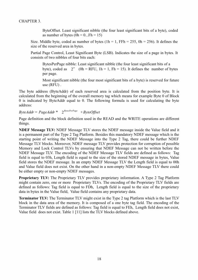
different formats, one byte format and the three consecutive bytes format. Presence of the length field depends on the tag field value. Interpretation of one byte format is that the lenght of the value field is between 00h and FEh bytes. If the value contains FFh, it is interpreted as flag specifying that the length field is composed of more than one byte. Three consecutive bytes format is used to specify that the length of the value field is between 00FFh and FFFEh bytes. The first byte FFh is a flag revealing that two more bytes are present. Those two bytes are interpreted as a word indicating the order if the value is between 00FFh and FFFEh. Figure 3 [11] shows the two different length field layouts.
1 byte format
3 bytes format
Figure 3.1.3: Length Fields Formats.
V (value field or V field): This field is about the value. If the value of the length is 00h or if it is completely missing , the value field also does not exist meaning that TLV block is empty. Otherwise the length field presents a length of N consecutive bytes, where N > 0.
TLV blocks are written inside the data area in a specific order. In order to write the TLV blocks NDEF Message TLVs and Proprietary TLVs should be present after all Lock Control TLVs and Memory Control TLVs. The Terminator TLV should be the last TLV block if it is present. In the reading process the TLV blocks making use of the reserved tag field values are jumped over by reading the length field and checking the length of the value field.
There are some TLV blocks which are important to be defined.
Null TLV: The null TLV might be used for padding of the data area of the memory. There could be none, one or more NULL TLVs in a Type 2 Tag. NULL TLV is composed of only the Tag field and thus it is one byte long. The encoding of the tag field of the NULL TLV is formed from the following fileds: Tag field is equal to 00h, Length field is not present and Value field is not present.
Lock Control TLV: Main functionality of the lock control TLV is to provide control information about the lock areas where the dynamic lock bytes are located, because their positions inside the tag can change. Each Lock Control TLV presents a single lock area. In order to define more lock areas, seperate Lock Control TLV blocks are needed to be used. The encoding of the TLV fields of the Lock Control TLV are formed from the following fileds: Tag field which is equal to 01h, Length field which is equal to 03h and the Value field. Value field is formed of 3 bytes and these bytes uniquely identify the position and the size of the lock area. These bytes also identify the number of bytes locked by each bit of the dynamic lock bytes. The encoding of these 3 bytes are defined as follows:
Position, Most Significant Byte (MSB). This indicates the position of the lock area in the memory. The position byte consists of two parts:
PagesAddr. Most significant nibble (the four most significant bits of a byte), coded as number of pages (0h = 0...Fh = 15)
17
00h-FEh
FFh 00FFh- FFFEh
CHAPTER 3.
ByteOffset. Least significant nibble (the four least significant bits of a byte), coded as number of bytes (0h = 0...Fh = 15)
Size. Middle byte, coded as number of bytes (1h = 1, FFh = 255, 0h = 256). It defines the size of the reserved area in bytes.
Partial Page Control, Least Significant Byte (LSB). Indicates the size of a page in bytes. It consists of two nibbles of four bits each:
BytesPerPage nibble: Least significant nibble (the four least significant bits of a byte), coded as 2n (0h = RFU, 1h = 1, Fh = 15). It defines the number of bytes per page.
Most significant nibble (the four most significant bits of a byte) is reserved for future use (RFU) .
The byte address (ByteAddr) of each reserved area is calculated from the position byte. It is calculated from the beginning of the overall memory tag which means for example Byte 0 of Block 0 is indicated by ByteAddr equal to 0. The following formula is used for calculating the byte address:
ByteAddr = PageAddr * 2BytesPerPage +ByteOffset
Page definition and the block definition used in the READ and the WRITE operations are different things.
NDEF Message TLV: NDEF Message TLV stores the NDEF message inside the Value field and it is a permanent part of the Type 2 Tag Platform. Besides this mandatory NDEF message which is the starting point of writing the NDEF Message into the Type 2 Tag, there could be further NDEF Message TLV blocks. Moreover, NDEF message TLV provides protection for corruption of possible Memory and Lock Control TLVs by ensuring that NDEF Message can not be written before the NDEF Message TLV. The encoding of the NDEF Message TLV fields are defined as follows: Tag field is equal to 03h, Length field is equal to the size of the stored NDEF message in bytes, Value field stores the NDEF message. In an empty NDEF Message TLV the Length field is equal to 00h and Value field does not exist. On the other hand in a non-empty NDEF Message TLV there could be either empty or non-empty NDEF messages.
Proprietary TLV: The Proprietary TLV provides proprietary information. A Type 2 Tag Platform might contain zero, one or more Proprietary TLVs. The encoding of the Proprietary TLV fields are defined as follows: Tag field is equal to FDh, Length field is equal to the size of the proprietary data in bytes in the Value field, Value field contains any proprietary data.
Terminator TLV: The Terminator TLV might exist in the Type 2 tag Platform which is the last TLV block in the data area of the memory. It is composed of a one byte tag field. The encoding of the Terminator TLV fields are defined as follows: Tag field is equal to FEh, Length field does not exist, Value field does not exist. Table 1 [11] lists the TLV blocks defined above.
18
CHAPTER 3.
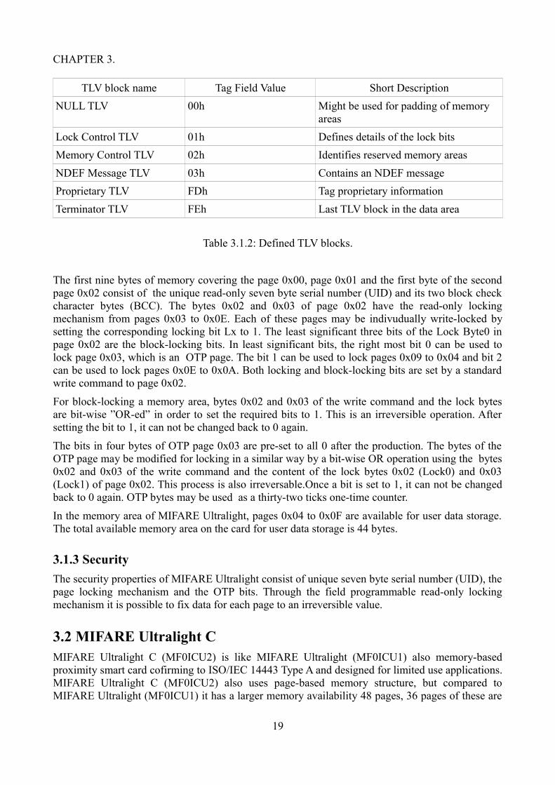
TLV block name Tag Field Value Short Description
NULL TLV 00h Might be used for padding of memory areas
Lock Control TLV 01h Defines details of the lock bits
Memory Control TLV 02h Identifies reserved memory areas
NDEF Message TLV 03h Contains an NDEF message
Proprietary TLV FDh Tag proprietary information
Terminator TLV FEh Last TLV block in the data area
Table 3.1.2: Defined TLV blocks.
The first nine bytes of memory covering the page 0x00, page 0x01 and the first byte of the second page 0x02 consist of the unique read-only seven byte serial number (UID) and its two block check character bytes (BCC). The bytes 0x02 and 0x03 of page 0x02 have the read-only locking mechanism from pages 0x03 to 0x0E. Each of these pages may be indivudually write-locked by setting the corresponding locking bit Lx to 1. The least significant three bits of the Lock Byte0 in page 0x02 are the block-locking bits. In least significant bits, the right most bit 0 can be used to lock page 0x03, which is an OTP page. The bit 1 can be used to lock pages 0x09 to 0x04 and bit 2 can be used to lock pages 0x0E to 0x0A. Both locking and block-locking bits are set by a standard write command to page 0x02.
For block-locking a memory area, bytes 0x02 and 0x03 of the write command and the lock bytes are bit-wise ”OR-ed” in order to set the required bits to 1. This is an irreversible operation. After setting the bit to 1, it can not be changed back to 0 again.
The bits in four bytes of OTP page 0x03 are pre-set to all 0 after the production. The bytes of the OTP page may be modified for locking in a similar way by a bit-wise OR operation using the bytes 0x02 and 0x03 of the write command and the content of the lock bytes 0x02 (Lock0) and 0x03 (Lock1) of page 0x02. This process is also irreversable.Once a bit is set to 1, it can not be changed back to 0 again. OTP bytes may be used as a thirty-two ticks one-time counter.
In the memory area of MIFARE Ultralight, pages 0x04 to 0x0F are available for user data storage. The total available memory area on the card for user data storage is 44 bytes.
3.1.3 Security
The security properties of MIFARE Ultralight consist of unique seven byte serial number (UID), the page locking mechanism and the OTP bits. Through the field programmable read-only locking mechanism it is possible to fix data for each page to an irreversible value.
3.2 MIFARE Ultralight CMIFARE Ultralight C (MF0ICU2) is like MIFARE Ultralight (MF0ICU1) also memory-based proximity smart card cofirming to ISO/IEC 14443 Type A and designed for limited use applications. MIFARE Ultralight C (MF0ICU2) also uses page-based memory structure, but compared to MIFARE Ultralight (MF0ICU1) it has a larger memory availability 48 pages, 36 pages of these are
19
CHAPTER 3.
user read/write area. MIFARE Ultralight C has additional features of having the 16-bit counter and the 2K3DES authentication mechanism for increased security. Content manipulation of an MIFARE Ultralight C smart card is also done using the Read and Write commands. Read command processing user data and access security configurations from pages and Write command handling to update user data and modify security configurations both commands accessing one page at a time. Mechanisms relating locking and one time programmable bits (OTP) are exceptions to this. Access control system of Ultralight C restricts the memory pages relating which pages to read and write. Table 2 shows the commands available for the manipulation of MIFARE Ultralight C smart card. The list of commands of MIFARE Ultralight C consist of Authenticate Command, Read Command and Write Command.
3.2.1 Memory organization
MIFARE Ultralight C has also page-based memory structure. Memory is organized in 48 pages, each page is 4 bytes in size, total EEPROM memory size is 192 bytes. The memory layout of Ultralight C is presented in Figure 3.2.1. The first nine bytes of memory covering the page 0x00, page 0x01 and the first byte of the second page 0x02 consist of the unique read-only seven byte serial number (UID) and its two block check character bytes (BCC). The bytes Lock0 and Lock1 of page 2 provide the lock mechanism for pages 3 to 15. One time programmable bits (OTP) are on page 3. Pages to store user data cover the memory area of 144 bytes, from page 4 to page 39. Lock mechanism for pages 16 to 47 contained in the first two bytes of page 40. 16-bit one-way counter is located in the first two bytes of page 41. Authentication configuration is stored in the first byte of page 42 and first byte of page 43. 2K3DES secret key is stored in the pages from 44 to 47.
20

CHAPTER 3.
Byte Number 0x00 0x01 0x02 0x03
Page 00H UID UID UID BCC0 Page 0
Page 01H UID UID UID UID Page 1
Page 02H BCC1 Internal LOCK0 LOCK1 Page 2
Page 03H OTP OTP OTP OTP Page 3
Page 04H User Data User Data User Data User Data Page 4
... ... ... ... ... ...
Page 27H User Data User Data User Data User Data Page 39
Page 28H LOCK2 LOCK3 Page 40
Page 29H Counter Counter Page 41
Page 2AH AUTH0 Page 42
Page 2BH AUTH1 Page 43
Page 2CH K1/0 K1/1 K1/2 K1/3 Page 44
Page 2DH K1/4 K1/5 K1/6 K1/7 Page 45
Page 2EH K2/0 K2/1 K2/2 K2/3 Page 46
Page 2FH K2/4 K2/5 K2/6 K2/7 Page 47
Figure 3.2.1: Memory layout of MIFARE Ultralight C.
3.2.2 Security
Security properties of Ultralight C covers the unique 7 byte serial number (UID), lock bytes of page locking mechanism, one time programmable bits (OTP), 16-bit one way counter and the 3DES authentication.
The unique 7 byte serial number (UID) are programmed and write-protected after production along with its two Block Check Character Bytes (BCC). These compose the first 9 bytes of the memory.
Figure 3.2.2: UID/serial number [22].
21

CHAPTER 3.
The BBC calculation is defined according to ISO/IEC14443-3 as CT Å SN0 Å SN1 Å SN2 for BCC0 and as SN3 Å SN4 Å SN5 Å SN6 for BCC1. CT is defined as cascade tag byte. SN0 holds the Manufacturer ID for NXP (04h) according to ISO/IEC14443-3 and ISO/IEC 7816-6 AMD.1.
Even though parts of the memory area can be locked through the lock bytes, raeding from user memory area can not be prevented by this functionality. Instead with the help of 3DES authentication access restrictions to the pages can be possible. As depicted in figure 3.2.1, LOCK0 and LOCK1 are located in the last two bytes of page 2. LOCK2 and LOCK3 are located in the first two bytes of page 40. The user data pages from page 4 to page 39 can be locked in blocks. Page 3 contains 8 bytes of OTP bits. OTP bits are pre-set to zero after the production. They can be bit-wise modified individually and only for once by a WRITE command. The 16-bit one-way counter is located in page 41. It can be one-way used to keep track of an incrementing value. The default value for the counter is set to 0000h. The applied encryption algorithm of 3DES authentication used in Ultralight C is 2 key 3DES encryption. This means that two entities have the same secret and each entity can be seen as a reliable partner for the coming communication. AUTH0 and AUTH1 are authentication configuration bytes. They are used to restrict write or read and write access to pages. AUTH0 contains a page number which defines the page limits of the settings in AUTH1 in hexadecimal number. Setting the AUTH0 to 30h (48 in decimal) means no restriction since there are 2f (47 in decimal) memory pages. The configuration of AUTH1 as 01h relates to restricted write access and configuration of AUTH1 as 00h relates to restricted read and write access. Access to the restricted pages demands successful authentication. Pages from 44 to 47 contain the 2K3DES secret key which can also be locked as a single block.
3.3 MIFARE DESFire EV1DESFire EV1 is a contactless smart card based on open global standards for both its interface and cryptographic methods. The name ”DESFire” is said to be assertive by refering with DES the high level of security using a 3DES or AES hardware cryptographic engine for enciphering transmission data and by refering with Fire its properties as a fast, innovative, reliable and secure IC.
DESFire EV1 has a flexible file system and can hold up 28 applications simultaneously and 32 files per application, consisting of five different file types: standard data file, back-up data file, value file, linear record file and cyclic record file. File size is determined during the creation. Each of these files can have up to fourteen keys associated with it and has its own file settings, which include communication mode and access control parameters. The communication modes include the plain, maced and enciphered modes.
As for the security, each DESFire EV1 has unique 7 bytes serial number, a single PICC master key and up to 14 keys per application. DESFire EV1 also supports DES, 2K3DES, 3K3DES and AES authentication as well as application level authentication, hardware exception sensors and self-securing file system. DESFire EV1 is backward compatible with its predecessor DESFire MF3ICD40. In 2011, the security of DESFire MF3ICD40 was broken by the power analysis attack [12] through which the secret key was able to be retrieved.
Probably due to security concerns, the specification of DESFire EV1 is not publicly available. Main source of information about DESFire EV1 is mainly available and reachable through search engines in relevant sites, blogs and forums, not always very complete in the case of specific details though.
22

CHAPTER 3.
3.3.1 Commands
DESFire EV1 commands are grouped in four different levels: security-related commands, smart card DESFire EV1 or PICC-level commands, application-level commands and data manipulation i.e. file-level commands [13].
Security-related commands involved with the authentication and key-related operations. Smart card or PICC-level commands present application and memory manipulation operations. Application-level commands involved with the operations to manipulate files. File-level commands include operations that manipulate data. Table 3.1 lists the commands organized by level.
Level Commands
Security-related Authenticate, ChangeKeySettings, SetConfiguration, ChangeKey, GetKeyVersion
(Smart card MIFARE DESFire EV1) PICC-level
CreateApplication, DeleteApplication, GetApplicationIDs, FreeMemory, GetDFNames, GetKeySettings, SelectApplication, FormatMF3ICD81, GetVersion, GetCardUID
Application-level GetFileIDs, GetFileSettings, ChangeFileSettings, CreateStdDataFile,CreateBackupDataFile, CreateValueFile, CreateLinearRecordFile,CreateCyclicRecordFile, DeleteFile
File-level ReadData, WriteData, GetValue, Credit, Debit, LimitedCredit, WriteRecord, ReadRecords, ClearRecordFile, CommitTransaction,AbortTransaction
Table 3.3.1: List of commands grouped by level for DESFire EV1.
23

CHAPTER 3.
3.3.2 File system
File type Description Commands
Standard data file Storage of unformatted userdata
ReadDataWriteData*
Backup data file Storage of unformatted userdata + integrated backupmechanism
ReadDataWriteData*CommitTransactionAbortTransaction
Value file Storage and manipulation ofa 32-bit signed integer
ReadDataWriteData*GetValueCredit*Debit*LimitedCredit*CommitTransactionAbortTransaction
Linear record file Storage of structured userdata(e.g. loyalty programs)
WriteRecord*ReadRecordsClearRecordFile*CommitTransactionAbortTransaction
Cyclic record file Storage of structured userdata + automaticallyoverwrite oldest record whenfull(e.g. logging transactions)
WriteRecord*ReadRecordsClearRecordFile*CommitTransactionAbortTransaction
Table 3.3.2: DESFire EV1 file types and data manipulation operations. The starred commands require validation [14].
DESFire EV1 file structure is flexible. It allows 28 applications where each application is defined by a 3-byte application identifier (AID). The 3-byte application identifier is set on file creation. Each of these applications contais 32 files, which in turn is defined by a 1-byte file number, that is also set on file creation. Access rights to these files may differ, some files requiring a preceding authentication. Access rights control the access to files. Besides the ChangeFileSettings command which is an application level command, there are four different, file-level, access rights for a file: Read Access (GetValue, Debit for Value files), Write Access (GetValue, Debit, LimitedCredit for Value files), Read&Write Access (GetValue, Debit, LimitedCredit, Credit for Value files) and ChangeAccessRights. Each of the Access Rights is coded in 4 bits, which is called a nibble. Each nibble refers to a link to one of the 1 to 14 keys which is set when the file is created and located within the respective application's key file. The minimum requirement for referencing a key contains the condition that referenced key should exist. There are two special key values 0xE and
24
CHAPTER 3.
0xF. 0xE means free access which is always granted regardless of a preceding authentication prerequisite. 0xF means deny access which is always denied regardless of the preceding authentication prerequisite. If in a given command one of the access rights is acknowledged, command is succesfull even though there are other access rights set to the given command. If one of the access rights of a given command contains the free access value of 0xE, the communication mode is forced to plain, ignoring the authentication phase, which also means that the communication settings of the file is ignored. On the other hand if one of the access rights of a given command refers to the key number associated with the authentication, communication is based on the communication settings of that file. Communication settings in turn determines which communication mode to use on that particular file. In case of the situation where non of these access rights of the given command does not refer to the authenticated key number and does not contain the free access value of 0xE, the command fails.
DESFire EV1 supports plain, maced and enciphered communication modes. File settings of the file in question and the command executed on it determine the type of the communication mode. Plain type is the default communication mode for all the commands. File settings of a file define the structural properties of the different file types such as the file size for data files, the record size, current number of records, boundaries for record files the boundary values, state of the limited credit option for value files.
Each file has an application master key. Smart card or PICC has a single master key and 14 keys per file. Key number for application master key and the PICC master key is 00h. If a successful execution of a command requires preceding authentication or not depends on the PICC master key settings, on the application master key settings or on the access right of files, such as whether a preceding authentication is required to access the file or not and if an authentication is required, which key number the reader device should used to authenticate.
3.3.3 Security
DESFire EV1 smart cards have several different security properties to ensure the reliability. Each smart card is provided with a 7 byte unique UID which is unchangeable and programmed into the device during production. This unique UID can be used in providing diversified keys which in turn, can be used in anti-cloning of the smart cards. Cyclic redundancy check (CRC) error detecting codes of CRC16 and CRC32 are used to detect accidental changes to the data. Data authenticity and integrity of message authentication is provided with the cipher block chaining message authentication code (CBC-MAC) and Cipher-based MAC (CMAC) codes. The CRC16 and the CBC-MAC are calculated merely for the data to be secured, in other words, the data to be stored on the card when sending commands from the PCD to PICC as well as receiving responses from PICC to PCD through APDU. On the other hand The CRC32 and the CMAC are calculated for the command code, headers and data for commands from the PCD to PICC send through APDU, and for the status code and data, in the case of possible responses, from PICC to PCD received through APDU.
DESFire EV1 ensures data confidentiality by the encryption algorithms DES, 2K3DES, 3K3DES and AES. Depending on the type of the applied encryption and decryption, before the data transmission between MIFARE DESFire EV1 and PCD a mutual three pass authentication can be done using DES, 3DES and AES on the bases of the configuration employing either 56-bit DES (single DES, DES), 112-bit 3DES (triple DES, 2K3DES), 168-bit 3DES (3 key triple DES,
3K3DES) or AES. Successful authentication provides a common secret (DES/3DES key) for MIFARE DESFire EV1 and PCD ensuring a trusted link between both parties. This secret key is the
25

CHAPTER 3.
result of a successful authentication between two parties.
The two basic cryptographic operations of the mutual 3-pass authentication are encipherment and decipherment. Mode of cryptographic operations depends on the type of the DES-encryption or used DES keys. In using the DES and 2K3DES encryption, PCD decrypts the data and the PICC encrypts the data. In using the 3K3DES or AES, the PCD encrypts when sending data and decrypts when receiving data. Data block size for DES and triple DES including 2K3DES, 3K3DES is 8 bytes and for AES 16 bytes which imply that the data length must be multiple of 8 bytes. When necessary it is padded with zeros to a length of multiples of 8 bytes. An important feature in cryptographic operations is that they are done in cipher block chaining mode. Prominent implication of the cipher block chaining mode is to make the result of the previous operation to be the initialization vector of the next cryptographic operation, during which, for sending data CBC send mode and for receiving data CBC receive mode is used. The differences in the algorithm of encryption and decryption are on the length of the random numbers generated, which is 8 bytes for DES and 2K3DES and 16 bytes for 3K3DES and AES. The other one is the session key generation algorithm.
3.4 NDEF standardThe NFC Forum has defined a standard the NFC Data Exchange Format (NDEF) which is a lightweight binary message format encapsulating and identifying one or more application defined payloads of arbitrary type and size into a single message that is exchanged between NFC-enabled devices. An example for this kind of device is NFC Forum Type Tag, such as a contactless smart card, which is capable of storing NDEF formatted data. Combination of NDEF and NFC Tags has given rise to the new kinds of applications based on NFC such as Smart Poster, activation of SMS services available, automatic wireless communication configuration (such as Bluetooth and WiFi handover), and electronic business card exchange. The focus of this section is on the NFC Tags which comply with the NFC Forum Type 1-4 Tag Platforms.
Storing application data into the NFC Tag follows certain structure: it should be first encapsulated into a NDEF message and then into the data structure specified by the NFC Type 1-4 Tag Platforms. The most important feature of NDEF message and the NFC Type Tag Platform encapsulations are in identifying the type of application data, such as a URL, vCard or JPEG image and also ensuring the interoperability and the coexistence of applications. The following Figure 3.4 [15] depicts the encapsulation of application data within a NFC Tag.
26
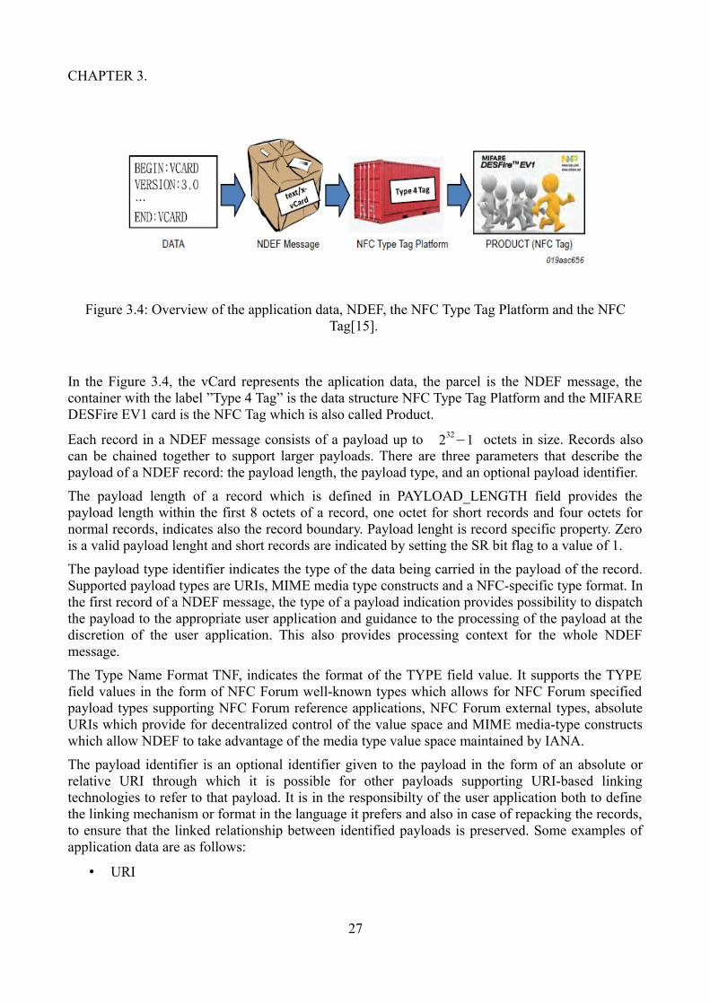
CHAPTER 3.
Figure 3.4: Overview of the application data, NDEF, the NFC Type Tag Platform and the NFC Tag[15].
In the Figure 3.4, the vCard represents the aplication data, the parcel is the NDEF message, the container with the label ”Type 4 Tag” is the data structure NFC Type Tag Platform and the MIFARE DESFire EV1 card is the NFC Tag which is also called Product.
Each record in a NDEF message consists of a payload up to 232−1 octets in size. Records also
can be chained together to support larger payloads. There are three parameters that describe the payload of a NDEF record: the payload length, the payload type, and an optional payload identifier.
The payload length of a record which is defined in PAYLOAD_LENGTH field provides the payload length within the first 8 octets of a record, one octet for short records and four octets for normal records, indicates also the record boundary. Payload lenght is record specific property. Zero is a valid payload lenght and short records are indicated by setting the SR bit flag to a value of 1.
The payload type identifier indicates the type of the data being carried in the payload of the record. Supported payload types are URIs, MIME media type constructs and a NFC-specific type format. In the first record of a NDEF message, the type of a payload indication provides possibility to dispatch the payload to the appropriate user application and guidance to the processing of the payload at the discretion of the user application. This also provides processing context for the whole NDEF message.
The Type Name Format TNF, indicates the format of the TYPE field value. It supports the TYPE field values in the form of NFC Forum well-known types which allows for NFC Forum specified payload types supporting NFC Forum reference applications, NFC Forum external types, absolute URIs which provide for decentralized control of the value space and MIME media-type constructs which allow NDEF to take advantage of the media type value space maintained by IANA.
The payload identifier is an optional identifier given to the payload in the form of an absolute or relative URI through which it is possible for other payloads supporting URI-based linking technologies to refer to that payload. It is in the responsibilty of the user application both to define the linking mechanism or format in the language it prefers and also in case of repacking the records, to ensure that the linked relationship between identified payloads is preserved. Some examples of application data are as follows:
• URI
27

CHAPTER 3.
- URL: ”http://www.aalto.fi/en”
- Telephone number: ”tel:+358 50 1234 5678”
- SMS: ”sms:+3585012345678?Body=Hi!”
- E-mail: ”mailto:[email protected]”
• Text
- ”Hello World!”
- ”Aalto University web-site”
• Smart Poster = Text + URI +…
- ”Aalto University web-site” + ”http://www.aalto.fi/en”
• Handover parameters
- Bluetooth parameters: Bluetooth address…
- WiFi parameters: SSID…
• Business card
- vCard
• Signature
28

CHAPTER 3.
3.4.1 NDEF Record Layout
NDEF records have a common format but can be in different length. Figure 3.4.1 [16] illustrates the format of the NDEF record with all the individual record fields.
Figure 3.4.1: NDEF Record Layout [16].
MB (Message Begin): The MB flag is a 1-bit field, when set, it indicates the start of a NDEF message.
ME (Message End): The ME flag is a 1-bit field, when set, it indicates the end of a NDEF message. However, in case of a chunked payload, the ME flag is set only in the terminating record chunk of the payload.
CF (Chunk Flag): The CF flag is a 1-bit field which also relates to the chunked payload. It indicates whether it is the first record chunk or a middle record chunk of a chunked payload.
SR (Short Record): The SR flag is a 1-bit field, if set defining that the PAYLOAD_LENGTH field is a single octet. The short record layout is for compact encapsulation of small payloads which will fit within PAYLOAD fields of size ranging between 0 to 255 octets. While NDEF parsers must accept normal and short record layouts, a single NDEF message may contain both normal and short
29

CHAPTER 3.
records. Figure 3.4.2 [16] illustrates the NDEF short record layout where the 1-bit SR flag is set to 1.
Figure 3.4.2: NDEF Short-Record Layout (SR=1) [16].
IL (ID_LENGTH field is present): The IL flag is a 1-bit field in the header as a single octect and if set, defines that the ID_LENGTH field is present. If the value of IL flag is zero then the ID_LENGTH field is omitted from the record header and the ID field is also omitted from the record.
TNF (Type Name Format): Type Name Format field defines the structure of the value of the TYPE field. This is a 3-bit field with the following values: Empty, NFC Forum well-known type, Media-type as defined in RFC 2046, Absolute URI as defined in RFC 3986, NFC Forum external type, Unknown, Unchanged, Reserved. Table 3.4.1 [16] illustrates the field values.
30

CHAPTER 3.
Type Name Format Value
Empty 0x00
NFC Forum well-known type 0x01
Media-type as defined in RFC 2046 0x02
Absolute URI as defined in RFC 3986 0x03
NFC Forum external type 0x04
Unknown 0x05
Unchanged 0x06
Reserved 0x07
Table 3.4.1: TNF Field Values [16].
Empty value 0x00 means that the record has no payload so there is no type either. When this value is used, the TYPE_LENGTH, ID_LENGTH and PAYLOAD_LENGTH fields are consequently zero and the TYPE, ID and PAYLOAD fields are omitted from the record. This value is useful when there is need for an empty record to terminate a NDEF message in cases where there is no payload defined by the user application. NFC Forum well-known type value 0x01 defines that this value of TYPE field complies with the RTD type name format defined in the NFC Forum RTD specification. Media-type value 0x02 defines that this value of TYPE field complies with the media-type BNF construct defined by RFC 2046. Absolute URI value 0x03 defines that this value of TYPE field complies with the absolute-URI BNF construct defined by RFC 3986. NFC Forum external type value 0x04 defines that this value of TYPE field complies with the type name format defined in [NFC RTD] for external type names. Unknown value 0x05 is used to define that the type of the payload is unknown. If used the value of the TYPE_LENGTH filed must be zero and consequently the TYPE filed is omitted from the NDEF record. The common recomendation is such that, if a NDEF parser receives a NDEF record like this, it should provide a mechanism to store but not to process the payload. Unchanged value 0x06 is used only in the middle record chunks and in the terminating record chunk used in chunked payloads, not in any other records. If used, the TYPE_LENGTH filed must be zero so consequently the TYPE field is omitted from the NDEF record. Reserved value 0x07 is a special value. It indicates that reserved or unassigned field values are for future use, moreover it should not be used. If a NDEF parser receives a NDEF record with an unknown or unsupported TNF field value should treat it as Unknown value of 0x05.
TYPE_LENGTH: This is an unsigned 8-bit integer field and it specifies the length in octets of the TYPE field. The TYPE_LENGTH field is always zero for certain values of the TNF field as mentioned above.
PAYLOAD_LENGTH: This field is an unsigned integer. It specifies the length in octets of the application payload. The size of the field is determined by the value of the SR flag. If the SR=1, the PAYLOAD_LENGTH field is a single octet representing an 8-bit unsigned integer. If the SR=0, the PAYLOAD_LENGTH field is four octets representing a 32-bit unsigned integer. In the transmission order of the octets, the most significant byte (MSB) is transmited first. Also a payload length of 0 is allowed in which case the PAYLOAD field is omitted from the NDEF record. Application payloads larger than 232
−1 octets are handled by using chunked payloads.
31
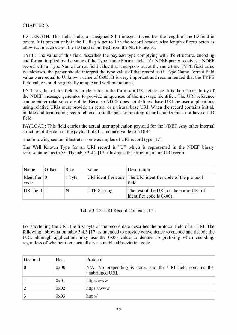
CHAPTER 3.
ID_LENGTH: This field is also an unsigned 8-bit integer. It specifies the length of the ID field in octets. It is present only if the IL flag is set to 1 in the record header. Also length of zero octets is allowed. In such cases, the ID field is omitted from the NDEF record.
TYPE: The value of this field describes the payload type complying with the structure, encoding and format implied by the value of the Type Name Format field. If a NDEF parser receives a NDEF record with a Type Name Format field value that it supports but at the same time TYPE field value is unknown, the parser should interpret the type value of that record as if Type Name Format field value were equal to Unknown value of 0x05. It is very important and recommended that the TYPE field value would be globally unique and well maintained.
ID: The value of this field is an identifier in the form of a URI reference. It is the responsibility of the NDEF message generator to provide uniqueness of the message identifier. The URI reference can be either relative or absolute. Because NDEF does not define a base URI the user applications using relative URIs must provide an actual or a virtual base URI. When the record contains initial, middle and terminating record chunks, middle and terminating record chunks must not have an ID field.
PAYLOAD: This field carries the actual user application payload for the NDEF. Any other internal structure of the data in the payload filed is inconceivable to NDEF.
The following section illustrates some examples of URI record type [17]:
The Well Known Type for an URI record is ”U” which is represented in the NDEF binary representation as 0x55. The table 3.4.2 [17] illustrates the structure of an URI record.
Name Offset Size Value Description
Identifier code
0 1 byte URI identifier code The URI identifier code of the protocol field.
URI field 1 N UTF-8 string The rest of the URI, or the entire URI (if identifier code is 0x00).
Table 3.4.2: URI Record Contents [17].
For shortening the URI, the first byte of the record data describes the protocol field of an URI. The following abbreviation table 3.4.3 [17] is intended to provide convenience to encode and decode the URI, although applications may use the 0x00 value to denote no prefixing when encoding, regardless of whether there actually is a suitable abbreviation code.
Decimal Hex Protocol
0 0x00 N/A. No prepending is done, and the URI field contains the unabridged URI.
1 0x01 http://www.
2 0x02 https://www
3 0x03 http://
32

CHAPTER 3.
4 0x04 https://
5 0x05 tel:
6 0x06 mailto:
7 0x07 ftp://anonymous:anonymous@
8 0x08 ftp://ftp.
9 0x09 ftps://
10 0x0A sftp://
11 0x0B smb://
12 0x0C nfs://
13 0x0D ftp://
14 0x0E dav://
15 0x0F news:
16 0x10 telnet://
17 0x11 imap:
18 0x12 rtsp://
19 0x13 urn:
20 0x14 pop:
21 0x15 sip:
22 0x16 sips:
23 0x17 tftp:
24 0x18 btspp://
25 0x19 btl2cap://
26 0x1A btgoep://
27 0x1B tcpobex://
28 0x1C irdaobex://
29 0x1D file://
30 0x1E urn:epc:id:
31 0x1F urn:epc:tag:
32 0x20 urn:epc:pat:
33 0x21 urn:epc:raw:
34 0x22 urn:epc:
35 0x23 urn:nfc:
36...255 0x24...0xFF RFU
Table 3.4.3: Abbreviation Table [17].
33

CHAPTER 3.
If the content of the value field is 0x02, and the content of the URI field reads as “nfc-forum.org”, the resulting URI is “https://www.nfc-forum.org”. If the content of the field is zero 0x00, then there is no prepending value. All fields marked RFU shall be treated as if they were value zero which means having no prepending value. A compliant system must not produce values that are marked RFU.
Following examples omit the MB and ME flags from the URI Record Type Definition and assume that the Short Record format is used. In order to put for example the URL http://www.nfc.com on a tag using the NDEF protocol, the following byte sequence should be followed:
Offset Content Explanation
0 0xD1 SR = 1, TNF = 0x01 (NFC Forum Well Known Type), ME=1, MB=1
1 0x01 Length of the Record Type (1 byte)
2 0x08 Length of the payload (8 bytes)
3 0x55 The URI record type (“U”)
4 0x01 URI identifier (“http://www.”)
5 0x6e 0x66 0x63 0x2e0x63 0x6f 0x6d
The string “nfc.com” in UTF-8.
Table 3.4.4: Simple URL with No Substitution [17].
To store a telephone number for example to make a mobile NFC device make a call to this number, the following byte sequence can be followed. Let's assume that the number is '358-9-1234567' making total length of data 17 bytes:
Offset Content Explanation
0 0xD1 SR = 1, TNF = 0x01 (NFC Forum Well Known Type), MB=1, ME=1
1 0x01 Length of the Record Type (1 byte)
2 0x0D Length of the payload (13 bytes)
3 0x55 The Record Name (“U”)
4 0x05 Abbreviation for “tel:”
5 0x2b 0x33 0x35 0x38 0x39 0x31 0x32 0x33 0x34 0x35 0x36 0x37
The string “+35891234567” in UTF-8.
Table 3.4.5: Storing a Telephone Number [17].
34

CHAPTER 3.
To store a proprietary URI, the following byte sequence can be used. The URI in this case is “mms://example.com/download.wmv”. Total length is 35 bytes:
Offset Content Explanation
0 0xD1 SR = 1, TNF = 0x01 (NFC Forum Well Known Type), MB=1, ME=1
1 0x01 Length of the Record Type (1 byte)
2 0x1F Length of the payload (31 bytes)
3 0x55 The Record Name (“U”)
4 0x00 No abbreviation
5 0x6d 0x6d 0x73 0x3a 0x2f 0x2f 0x65 0x78 0x61 0x6d 0x70 0x6c 0x65 0x2e 0x63 0x6f 0x6d 0x2f 0x64 0x6f 0x77 0x6e 0x6c 0x6f 0x61 0x64 0x2e 0x77 0x6d 0x76
The string “mms://example.com/download.wmv“.
Table 3.4.6: Storing a Proprietary URI on the Tag [17].
3.5 NFC Tag Use CasesThe NFC Tags provides variety of use cases. The following use cases mainly deals with the NFC Tags in the passive device form and illustrates the changes NFC Tags have brought to the everyday life.
Smart Poster use case: In the smart poster use case, a user using a NFC device such as a mobile phone touches to the NFC tag integrated into a poster to read the application data stored in it. The NFC application data in the smart poster can be the bus schedule user uses. This can contain three different options:
1. The NFC Tag can store the schedule information.
2. The NFC Tag can stores a website URL and the website has the schedule information.
3. The NFC Tag can store push registery data and additional service data needed for the mobile application to retreive actual schedule information from the server.
In the first option, touching the NFC Tag by a mobile phone transfers the bus schedule information to the user's phone and displays it.
In the second option, touching the NFC Tag by a mobile phone transfers the website URL to the user's phone. The phone processes the data and discovers that it is an URL. Phone launches the website with its browser and displays the bus schedule information.
In the third option, touching the NFC Tag by a mobile phone transfers the push registery and any required additional data for the application to process the data to the user's phone. Push registery
35

CHAPTER 3.
data helps to lauch the application in the user's phone automatically and displays the bus schedule information.
Handover use case: A handover use case refers to the exchange of configuration information through the NFC to easily establish a connection over Bluetooth or WiFi. An example of a Handover use case can be the following: the user using a NFC Device, such as a Personal Digital Assistant (PDA) or notebook touches the NFC Tag attached to the top of a WiFi router. The NFC Tag contains the configuration data that is transferred to the PDA or to the notebook to setup the Wireless LAN interface and to establish the wireless connection to the WiFi router.
vCard use case: In the vCard use case, a business card can contain an embedded NFC Tag with the person's details. A user can retreive and save the vCard information along with the possible JPEG image, if the memory space of the NFC Tag allows this, into his/her address book through a NFC device such as a mobile phone or a notebook without having to type manually all these information.
SMS use case: A user with the NFC-enabled device such as a mobile phone or notebook reads, for example, a NFC Tag integrated into the smart poster which contains a SMS. The user after reading this Tag sends the predefined SMS to retreive the ring tone shown by the NFC tag or to activate any SMS services available.
Call request use case: In a call request, a NFC enabled device calls a phone number optained from the NFC Tag. A user can write his/her phone number into the NFC Tag supplied probably also by a picture using a NFC enabled device such as a mobile phone or notebook. Another user can then read the NFC Tag by touching the picture with the NFC enabled phone and the phone automatically calls this person without any further action.
NFC ticketing use cases: A prominent use case of a NFC ticketing is travel card in public transportation in big cities. User buys his/her card from the vendor of the travel cards. The travel card can be charged according to the predefined different time periods starting from the minimum time period of two weeks onwards up to a month or even for a longer period of time. During the validity of the ticket, whenever user uses public transportation lets his/her NFC travel card read by the NFC enabled reader in the vehicle or hands it to the controller who reads the card by a mobile NFC enabled reader during random supervision. NFC reader confirms the validation of the tickect by a green light and a specific sound. Tickect invalidation is denoted with a red light and a related specific sound. The NFC reader device denotes the oncoming expiry time of the travel card by a green and yellow light combination and a related sound. The alternating option of buying a usage time for the travel card is to charge the travel card with the monetary value. In this case, user can pay for his/her public transportation in each usage seperately by holding the NFC enabled travel card in the close proximity of the NFC reader and pressing the travel zone button of his/her choice in the reader device. The NFC enabled reader device communicates with the NFC travel card and checks whether or not the available monetary value in the travel card is sufficent for the chosen travel zone. If there is sufficent monetary value in the travel card, the reader charges the sum from the balance of the card denoting the success of the operation by a green light, related sound and also displaying the related information on the device monitor. If the balance of the travel card is insufficent for the chosen travel zone, NFC reader device denotes this with a red light and a related sound. In some cities the user can even use the monetary value within the NFC enabled travel card for paying the entrance fee for public swimming pools equipped with the NFC enabled readers.
Another interesting use case for NFC ticketing is for movie tickets. Apart from the traditional method of selling the movie tickets, some movie theaters have choosen to promote new products to their users in the pursuit of brand awareness by providing their customers with the newly emerging technologies like NFC technology in the ticketing systems. In this use case the user selects the
36
CHAPTER 3.
movie, time and seat at the movie ticket vendor kiosk machine and then requests payment by touching his/her NFC enabled mobile phone to the NFC reader embedded on the kiosk machine. After the confirmation of the payment user touches another tag to transfer the tickect to his/her mobile phone. User then approaches the turnstile at the entrance of the movie theater and touches his/her mobile phone to the NFC reader on the turnstile. The NFC reader reads and processes it by sending the ticket information to the backend system in order to validate it. When the ticket is validated, turnstile opens and lets the user in.
37

CHAPTER 4.
Chapter 4
Applications of NFC tags and cardsThis chapter presents the different applications of NFC tags and cards and the diversity of their implementations. Examples of NFC applications of smart posters, ticketing, keys and access control, uses in library services, entertainment services, in social network services, in educational services, in location based services, in work force and retail management services and in healthcare are discussed in detail.
4.1 Smart PostersNFC Smart Posters are objects equipped with readable NFC tags placed on them, in the form of a poster, billboard, magazine page, flier or even a three-dimensional object. The common feature of these information tags is a NFC tag that has a NDEF message stored in it is embedded in the desired medium. When a NFC device is held close to the tag, the information stored in this NDEF information tag is read. Examples of such information include a poster with a web address for buying sports tickets, a timetable displayed at a bus stop and coupons inserted in a magazine advertisement. An important issue in smart posters is the touchpoint that indicates where users should hold their devices to read the tag. When designing the smart poster it is important to design it in such a way that the user should not waste time looking for the tag. This could be done by some textual sign or supplementary image that marks the touching point like a mobile phone image on the tag. The NFC Forum is promoting its N-Mark logo as the global symbol to indicate where NFC functionality is available, although not all of the end-users may be aware of the meaning of an N-Mark sign. The basic princibles of the NDEF technology is discussed in section 3.4 under the topic ”NDEF standart”.
Reading a NFC tag of the Smart Poster with a NFC phone, the user can easily initiate a phone call, send a SMS or open up a web-page in a browser by reading an URL embedded in the NDEF message of the tag, including the possibility of saving or editing these informations. It could even be an action which trigger an appication in the NFC phone.
A good example for the functionality of a Smart Poster could be a smart movie poster. In this use case when user touches the ”buy tickets” tag with the smart phone, this action would open web browser and the URL in tag leading the user to reserve and purchase the seats for the movie. At the end of the transaction the back end system sends the ticket as a SMS to the phone. The functionality of the smart poster could also be designed by programming the tag in such a way that user may retrieve more information about the movie before deciding to buy the tickets by touching ”more info” tag. This action would start to download a mini-trailer of the movie via URL from the movie's home page or Internet Movie Database. Another additional option on the Smart Poster could be ”download soundtrack” tag with the URL leading to the online music store. Besides this, a tag including an advertisement for a nearby restaurant offering discount accompanying with an other tag in the ad to reserve a table in a restaurant can also be placed on the poster. Touching the former
38

CHAPTER 4.
tag would save the discount offer in the form of SMS message and touching the latter tag would open an SMS template with some predefined text and user would type name and time and send the message for reservation. The Smart Poster could also include a tag which opens a navigation web page in the browser with the guidance to the movie teather. An example of a Smart Poster demonstrating services initiated and designed by VTT is illustrated in Figure 4.1 [23].
Figure 4.1: Smart Poster example [23].
NFC Forum Smart Poster white paper [24] discusses usage of Smart Posters around the world in the businesses, showing the versatile benefits of smart posters. Smart Posters are used in the tourism sector enables NFC device users to touch NFC Smart Posters at the memorial sites on each stage of the planned route of the visiting place to receive information and navigation, reducing the number
39

CHAPTER 4.
of the printed brochures used in the tourist industry and providing users with interactive and real-time information through the simplicity of touch. In museums, A NFC Smart Poster displaying where all the NFC-enhanced exhibitions were located in the museum can guide visitors to enhance their experience. In these specific locations, users by touching the NFC tags at the explicitly marked touchpoints near the selected exhibits could access more detailed information, including further text about the exhibit, photos, audio commentary, and video content.
Another dimension of Smart Posters is its use for educational purposes. Secondary school students were put to test to cope with everday life by teaching the necessary skills and knowledge and familiarizing them with the culture and history of their own city. This experiment transferred the educational setting from the classroom to the actual contextual environment, providing extra motivation to learn and build life-management skills and emphasizing that the school is part of the surrounding society and students learn from life in general. In the trail, students would receive text, video, or audio tracks relating to each checkpoint by touching the NFC Smart Posters. Along with this, they would also receive a map to the next checkpoint. The teachers were also provided with the possibility of monitoring the student’s progress, as the checkpoint information was sent back to a central system that the teacher could access via computer.
NFC Smart Posters can also be used for event management. Smart Posters display the information at the event, including the conference program and the exhibitor listing. Attendees are asked to discover further details by touching the tags on the NFC Smart Posters with their NFC mobile devices. A web page opens on the browser application of the device, displaying information on the speaker, company, or exhibitor. Meanwhile, NFC is also used for accessing attendee badge information for access control and business card exchange.
Another potential area of usage for Smart Posters is shopping. NFC Smart Posters were placed around the store advertising products. Touching a NFC Smart Poster would give users information on the particular product and would also reward them with additional points on their loyalty cards. When NFC devices were touched to the touchpoint, the Shopping Assistant application would compare the items on the shelf to those the customers were searching for and inform them if the products were on the aisle, eliminating unnecessary item hunting. The Shopping Assistant application could also display prices as well as allowing loyalty card holders to see the actual costs of products with member discounts applied, and how many loyalty points they would receive per product.
NFC Smart Posters are used in an innovative way for the targeted promotions which generates a much higher usage and redemption rate than normal promotions where they can add value to the entire mobile payment experience. NFC Smart Posters were used to deliver coupons and promotions to users targeted to their locations and personal profiles. Users tap their NFC phones at Smart Posters located in high-traffic areas to download coupons and discounts relevant to each person’s location and personal profile, which were stored in the mobile wallet and redeemed by waving the phone on contactless readers at the point of sale. Promotions included wide range of shopping categories of department stores, food courts at shopping malls, restaurants, bookstores, and theater multiplexes.
Other examples of usage of Smart Posters are elderly service meal orders where customers order their meals by touching NFC Smart Posters to choose dishes and then send the requests via the NFC device, remote worker reporting where remote workers confirm locations visited and tasks completed, and download updated information, weather forecasts where NFC Smart Posters provide users quick access to weather forecasts, maps where an interactive NFC Smart Poster map allows the user to download the map, get additional information on relevant services, and access coupons,
40

CHAPTER 4.
events calendar where users can download tickets or coupons from Smart Posters or be linked to event websites, taxi ordering where a NFC Smart Poster automates the process of ordering a taxi by sending the NFC Smart Poster’s location with the user’s details in a text message to the taxi stand.
4.2 TicketingNFC Forum document NFC in Public Transportation [25] describes the key ticketing service processes in four different steps: registration, provision, validation, and inspection.
Registration: There are different ticket types for the passangers. Majority of tickets available for passangers are full adult tickets for the relevant time of travel. Some subgroup of passangers are entitled to discounted fares such as children, seniors, students and they may also receive a concessionary ticket product that allows free travel or travel with certain time restrictions, such as off-peak only. These group of people may have to provide physical identification to the transport operator to demonstrate entitlement to this discounted fare. Many transport operators require registration before providing season tickets (weekly, monthly, annual), as these are sold at a reduced fare price compared to purchasing daily tickets. Before obtaining the reduced ticket fares, travelers need to provide evidence of eligibility through the registration process in advance which usually involves completing a special form and showing personal identification, if for example, the passanger is student, student card or required documents from the educational organization. In the countries or places where NFC-enabled mobile devices are used, the resulting electronic discount token or photo ID can be sent to an NFC-enabled phone and shown to the ticket sales agent. In places where NFC travel smart cards are used, these informations are registered or saved on the databases of the public transport operators or the local authorities which are available also to ticket sales agents or offices.
Provisioning: Passangers can provide their tickets from the ticket offices and retail agents of the transport operators in advance of their journey. The variety of these prepaid tickets can range from a single journey ticket of one transport mode to a ticket that entitles the passanger to unlimited travel across multiple travel modes for example from minimum period of two weeks up to the period of one year. Alternative means of providing tickets such as self service ticket issuing terminals and postpaid tickets or passes allow passangers to avoid lengthy lines at ticket offices. NFC enabled mobile devices make it feasible to purchase tickets at either ticket offices or kiosks, and then to download and store them. These devices also make it possible to provide tickets remotely over the air using a ticket distribution network. NFC smart card usage as passenger tickets in public transportation however will maintain its popularity as an affordable and pervaded alternative compared to costly NFC enabled mobile devices. Despite optimistic predictions, NFC-enabled mobile phones have yet to make an impact on the market.
Validation: In public transportation, passengers have to manually show or electronically present their valid tickets as they enter a transport vehicle or a ticket validation area. In some transport modes passengers may obligated also to electronically present their valid tickets to exit the vehicle or ticket validation area.
In public vehicles such as busses, manual validation is conducted by the vehicle driver as passengers get in from the driver's side of the vehicle or a conductor or a guard on the trams. In some systems manual validation can also be performed by a ticket checker before passengers enter the boarding area of a train, underground or ferry. Most often common practice is to perform random checks of the valid passenger tickets in those public transportation vehicles by the ticket controllers.
41

CHAPTER 4.
Electronic validation of the tickets by readers on the vehicle or gate lines at the boarding points has been fast replacing the manual validation which makes the ticket validation operation much faster and reliable. This has led to the introduction of pay-as-you-go tickets. The passenger may load stored value on NFC-enabled phone or on the travel smart card. In the case of a travel smart card, this card can also hold seperately weekly, monthly or annual season tickets. With this stored value the passenger can pay separately for his public transportation for areas which are not covered in the season ticket or pay the ticket fare for the accompanying passengers. The validation devices deduct value from the stored balance as the passenger travels on the various transport modes that support the use of the technology. This in turn can significantly reduce the need to issue prepaid tickets.
A potential practice of ticket validation include the pay-after-you-travel tickets where a valid travel token on an NFC-enabled phone or contactless payment card is used as a guaranteed payment method to the transport operator. During the travel of the passenger use of the public transportation is registered by collecting the entry and exit validations, which are then priced in a centralized back-office fare generator, and an overall aggregated charge can be made to the associated bankcard account. Use of such method would diminish the need for a software of the validation readers which hold all fare tables and fare pricing to support pay-as-you-go product fare calculations. Application of this new method pay-as-you-go in ticket validation in turn can eliminate the need to obtain travel smart card or prepaid ticket. This would mean a significant reduce for ticket-selling offices and associated commissions costs.
4.2.1 Ticket implementation options
Open (Ungated) Systems: In a conventional transportation systems that are not gated and where paper tickets are not used, a transport application can be loaded on an NFC-enabled phone.
The main actors of the system are NFC-enabled phone and a NFC Forum Compliant tag. The passenger registers a trip in the system or purchases a ticket by tapping a NFC-enabled phone against the NFC Forum tag at the departure station. The transport application either receives data about the current location from the tag or information in the tag opens a dedicated website prompting the passenger to enter a destination either from a personalized list of preferred locations or by entering it manually from the phone’s keyboard.
To purchase a ticket or to register a trip in the system, the passenger taps an NFC-enabled phone against the NFC Forum tag at the departure station. The tag provides data about the current location to the transport application or opens a dedicated website that then prompts the traveler to enter a destination. The destination can be selected either from a personalized list of preferred locations or entered with the phone’s keyboard.
Vital identification process of the customer for the system is done by using either the phone number or a unique ID stored in the application in the phone.
Passenger fed departure and destination data, as well as the customer’s identifier, is sent to a back-end system over the air. On the bases of the entered data, the back-end system provides feedback about ticket and travel options. Available system options as well as customer’s selection, determines whether a valid ticket is sent to the phone either as an SMS or a 2D barcode in the Java MIDlet. 2D barcode can be read using a regular barcode reader. An other option is to store the ticket in the phone’s secure element for security reasons. The ticket can then be inspected using a contactless reader. The passenger can be charged for the ticket on a separate bill which is paid to the system provider. Alternative option to the separate billing is to link the charge for the ticket to the passenger’s mobile phone bill provided that the service provider and the mobile network operator
42

CHAPTER 4.
have an agreement about this in order to make the system to work.
Another different version is the system where transport operator wants to offer a check-in/check-out travel product. In this system the NFC-enabled phone transmits the relevant readings of NFC Forum tags at departure station as check-in touchpoint and at destination station as check-out touchpoint to a back-end system. Ticket fares are calculated by the back-end system. Payment arrangements with the mobile operators or banks and registration of the passenger's NFC-enabled mobile devices are basic prerequisite of this version of the system.
Controlled Entry Systems: Controlled Entry Systems have electronic validators namely NFC readers accepting contactless cards at entry points on transport vehicles or in a boarding area. System requirement defines the arrangement of the transport application which already exists in the contactless smart cards to be placed on a secure element in the NFC-enabled mobile devices.This is handled by the transport operators. Same functionalities prevail with both the transport application in mobile devices and contactless smart cards. As the passengers enter the transport vehicle, they touch their NFC-enabled mobile devices against the NFC reader and can travel, add new prepaid tickets, and supplement pay-as-you-go value. Passengers using NFC-enabled mobile devices can also display the ticket and resulting stored value balance information in their mobile devices. Whereas contactless smart cards users can check the same information on the display of the NFC-readers by holding their cards against the NFC-readers for a few more seconds than the time required for tickect validation.
An advantage for the NFC-enabled mobile devices can be to enhance the transport application to allow over-the-air ticket products to be added into the secure element as well as adding stored values over the air if the need for such an action arises. This in turn would be a cost effective implementation reducing the need to provide prepaid ticket selling facilities which reduces commission costs.
Gated Systems: Gated systems hosting utilization of contactless smart cards are used in many cities. Fare collecting in public tranportation has been made efficient with the implementation of the automatic and accurate system. Cooperation of transport operator and the NFC-enabled mobile device provider is necessary to support the installation of the local transport application on the secure element in the NFC-enabled mobile device. In the pursuit of using the same NFC-enabled mobile device in the wider area or in different cities and places outside of the local city the issue of whether multiple city transport applications can reside on the same secure element in an NFC-enabled mobile device is a matter of discussion and arrangement between the transit application owners and secure element owners. Possibility and feasibility of creating a global application on the secure element, such as a payment application that can be detected and is accepted in any transport system can be discussed as future options and concerns of stakeholders. Practical realization of such a system enhances the possibilities of the passengers to decide various payment options of paying by bankcard or using the relevant transport application as they travel domestically and internationally.
Smilar concerns prevail also for the contactless smart card systems. Feasibility of creating a global contactless smart card system that can be detected and is accepted in any transport system is an arguable option and matter of agreement of stakeholders.
The prominent advantage of using NFC-enabled mobile devices over the contactless smart cards is the capability of NFC-enabled mobile devices to automatically load tickets or value over the air using the mobile network.
43
CHAPTER 4.
4.3 NFC implementation in keys and access controlNFC technology is increasing its implementation potential to become a possible option for controlling access and authentication to homes and offices alike. Implementations of the NFC home securicty systems have started to emerge in the market. In September 2011, the key and lock company Yale unveiled their home security system Real Living Locks [26] introduced as the first NFC-operated lock on the market. In this system, users can by touching their mobile device unlock and enter home. Home electronics is also integrated in the system which allows users to control and monitor both the security system and other home systems like temperature adjustments and alarms. NXP Semiconductor has related implementation KeyLink Lite, a smart key for cars. Driver taps the NFC-enabled device to the smart key to open or lock the car. KeyLink Lite smart key also receives diagnostic information like gas and oil levels and note the GPS location of the car’s parking spot in a large lot.
In a pilot project at the Clarion Hotel in Stockholm Sweden [27] selected arriving hotel guests received NFC-enabled mobile devices. After booking their room in the usual way, via text message, the hotel guests receive booking confirmation on their NFC-enabled mobile devices. Before they arrive at the hotel, they receive a reminder to check in to their room through the NFC-enabled mobile devices, along with the the welcome message. When checked in, these guests received their electronic key directly on their mobile devices over-the-air. This helped them to skip the check in line at the reception desk, go straight to their room and open the door by tapping the NFC-enabled mobile devices on the door lock. After their stay, when leaving the hotel, the guests check out from their NFC-enabled mobile devices by touching the device to NFC-tags located around the hotel or through the mobile key application on their devices. The digital hotel room keys are then automatically deactivated. By this way, they eliminate the need to wait in lines of the hotel's reception desk. The system consists of a back-end infrastructure managing the distribution of door keys and a mobile key application residing on the guest’s NFC-enabled mobile device. The mobile key application stores the guest's door keys and travel applications provide the users the information about their hotel bookings.
Villanova University in US had also a similar project. In the project, access control credentials have been sent over the air to NFC devices, allowing students to use their NFC-enabled devices to enter buildings instead of physical keys. Students downloaded the required application to their NFC-enabled devices. Then they use this application to retrieve their secure mobile key that was set up by the access control site administrator. Opening the application and tapping it against the NFC reader like it would have been also in the case of a NFC smart card, provided the access to the premises.
4.4 NFC implementation in Library servicesLibraries want to develop their services through searching for new methods which would let library users to check out their own materials to minimize the routine library services, try to eliminate lines and wait times, and redeploy the staff to other service areas. With the system build by combining security properties of NFC, with the application installed on NFC-enabled mobile device along with the NFC tags enabling material identification, library users can complete the process of loaning material as soon as the material is taken from the shelf in any location within the library. Additional library services for customers would also include services like checking the due date or extending the lending period and manage their materials from wherever they are.
One important issue for libraries is to provide for the customers secure access at public computer
44

CHAPTER 4.
terminals and provide authentication for small group study rooms that require registration or key access. In this respect utilizing a system including security properties of NFC-enabled mobile devices and NFC readers could be the reasonable solution, eliminating the need to remember or enter a username and password combination.
An other beneficial use for the NFC could be to create interactive services for the customers. By touching to the relateg tags located throughout a library via their NFC-enabled mobile devices, users could reach resource recommendations based on their subject of interests, transactions history, or a predefined profile. The capacity advantage of NFC to perform multiple functions based on the functionality of the reader software, may offer users many supplementary details about a resource or object, along with the background information about the author, and additional informations such as access to related multimedia, connections to online links, or to display related resource guides [28].
4.5 NFC implementation in entertainment servicesNFC technology has already entered the entertainment world. Some prominent examples of multi-player parlor games implemented for NFC enabled mobile devices are Pass the Bomb and Exquisite Touch. In the game Pass the Bomb, a virtual bomb is passed from player to player in a circle by touching their NFC enabled mobile devices together.
Figure 4.5.1: Touch interaction: Example of players passing the bomb between devices [29].
Game starts with the activation of the bomb with a random countdown time until it reaches zero. If the countdown reaches zero despite of the attemps of the players to defuse it, the bomb explodes on the phone of the player who is currently holding it. This player is then eliminated from the game and cannot receive the bomb while the remaining players are allowed to restart the countdown
45

CHAPTER 4.
timer. In order to prevent this, each player receiving the bomb, tries to defuse it before allowed to pass it to the next player in the circle. Player can try to defuse the bomb by cutting one of three wires, selected by pressing the corresponding phone key. Each of these keys effects the countdown timer differently, increasing the speed of the countdown timer in varying modes, or resetting the countdown timer speed to normal. The game is equipped with different audio-visual effects to increase the excitement.
Figure 4.5.2: Game state diagram [29].
In the game Exquisite Touch, each player takes turn by writing words or phrases answering the questions of four different story options: Action, Comedy, Romance, and Adult, in order. Questions and the respective records are pre-set on the screen of the NFC-enabled mobile device.
A player starts the game by selecting the story type. After this the first question appears on the player's mobile device screen. The player is allowed to pass on the game to the next player by typing an answer. Passing on the game to the next player accomplished by touching the NFC devices together. Each answer of the each player is added to a string containing the story type. Each player while being unaware of all the answers of other players, respond all the subsequent questions of that particular story. The process being repeated until there are no questions left to ask. At this point, the last player sees a story on the screen of his/her device and has to read it out loud.
Another interesting example is Whack-a-Mole game adapted to the use of NFC. The game combines dynamic NFC display with tagged physical objects. The goal in the original Whack-a-
46
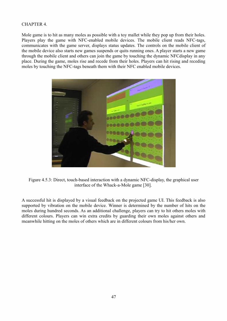
CHAPTER 4.
Mole game is to hit as many moles as possible with a toy mallet while they pop up from their holes. Players play the game with NFC-enabled mobile devices. The mobile client reads NFC-tags, communicates with the game server, displays status updates. The controls on the mobile client of the mobile device also starts new games suspends or quits running ones. A player starts a new game through the mobile client and others can join the game by touching the dynamic NFCdisplay in any place. During the game, moles rise and recede from their holes. Players can hit rising and receding moles by touching the NFC-tags beneath them with their NFC enabled mobile devices.
Figure 4.5.3: Direct, touch-based interaction with a dynamic NFC-display, the graphical user interface of the Whack-a-Mole game [30].
A successful hit is displayed by a visual feedback on the projected game UI. This feedback is also supported by vibration on the mobile device. Winner is determined by the number of hits on the moles during hundred seconds. As an additional challenge, players can try to hit others moles with different colours. Players can win extra credits by guarding their own moles against others and meanwhile hitting on the moles of others which are in different colours from his/her own.
47
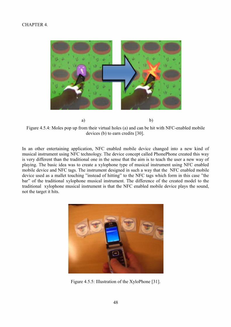
CHAPTER 4.
a) b)
Figure 4.5.4: Moles pop up from their virtual holes (a) and can be hit with NFC-enabled mobile devices (b) to earn credits [30].
In an other entertaining application, NFC enabled mobile device changed into a new kind of musical instrument using NFC technology. The device concept called PhonePhone created this way is very different than the traditional one in the sense that the aim is to teach the user a new way of playing. The basic idea was to create a xylophone type of musical instrument using NFC enabled mobile device and NFC tags. The instrument designed in such a way that the NFC enabled mobile device used as a mallet touching ”instead of hitting” to the NFC tags which form in this case ”the bar” of the traditional xylophone musical instrument. The difference of the created model to the traditional xylophone musical instrument is that the NFC enabled mobile device plays the sound, not the target it hits.
Figure 4.5.5: Illustration of the XyloPhone [31].
48
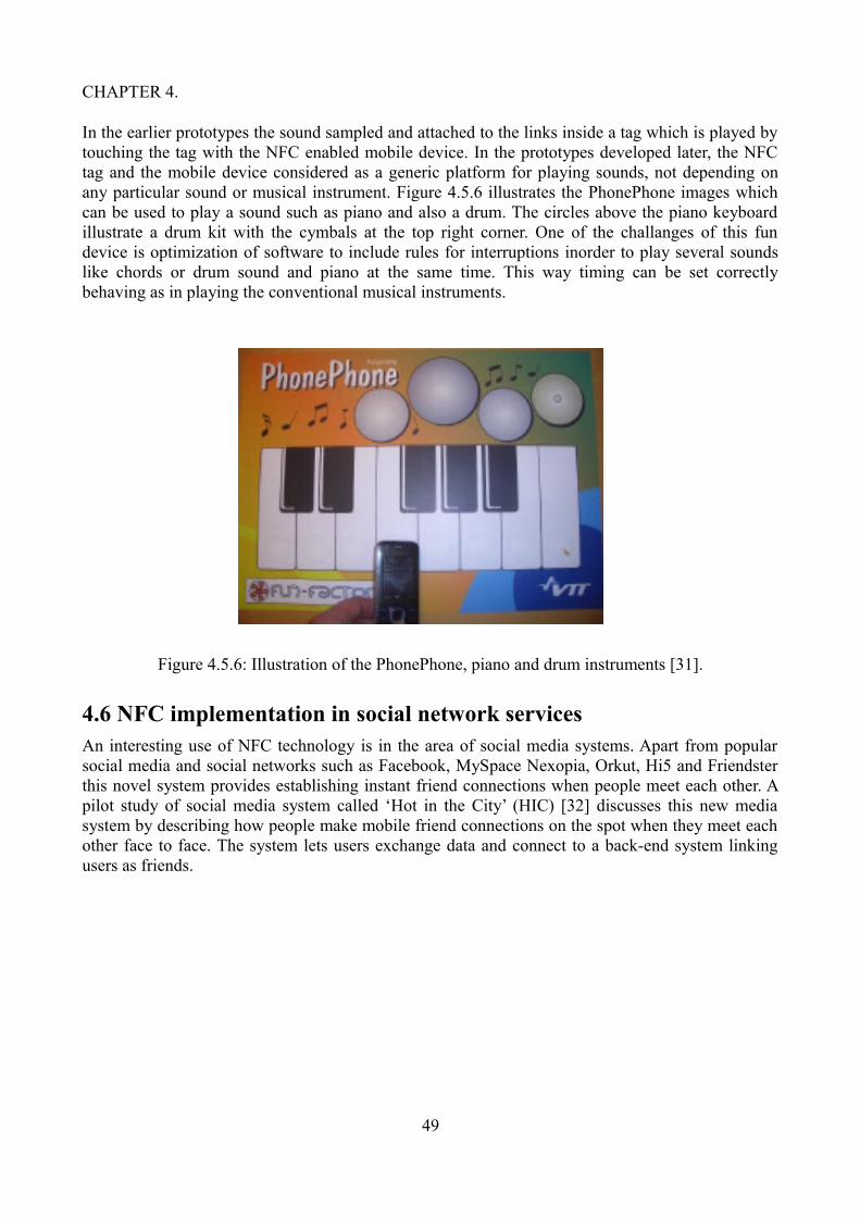
CHAPTER 4.
In the earlier prototypes the sound sampled and attached to the links inside a tag which is played by touching the tag with the NFC enabled mobile device. In the prototypes developed later, the NFC tag and the mobile device considered as a generic platform for playing sounds, not depending on any particular sound or musical instrument. Figure 4.5.6 illustrates the PhonePhone images which can be used to play a sound such as piano and also a drum. The circles above the piano keyboard illustrate a drum kit with the cymbals at the top right corner. One of the challanges of this fun device is optimization of software to include rules for interruptions inorder to play several sounds like chords or drum sound and piano at the same time. This way timing can be set correctly behaving as in playing the conventional musical instruments.
Figure 4.5.6: Illustration of the PhonePhone, piano and drum instruments [31].
4.6 NFC implementation in social network servicesAn interesting use of NFC technology is in the area of social media systems. Apart from popular social media and social networks such as Facebook, MySpace Nexopia, Orkut, Hi5 and Friendster this novel system provides establishing instant friend connections when people meet each other. A pilot study of social media system called ‘Hot in the City’ (HIC) [32] discusses this new media system by describing how people make mobile friend connections on the spot when they meet each other face to face. The system lets users exchange data and connect to a back-end system linking users as friends.
49
CHAPTER 4.
Figure 4.6.1: Illustration of the hotspot tag on the left and an event tag on the right [33].
As in the other social media systems, the importance of technological advances and social phenomena of friendship creation is taken into consideration, since event of friendship creation is local and individual, neither can it be predicted when it will happen.
Hot in the City is a social media application which allows users to make friends by touching other users’ NFC devices through the peer-to-peer mode as well as allowing them to inform friends of their current location by touching hotspot tags. Hotspots provide an important feature. Even though there are other location-aware services for social networks or established social networks used through a mobile interface using satellite positioning, a solution to the problem of indoor positioning that is often where people would like to be located by friends is provided by NFC through the context of social networking as people can be located by fixed hotspots. Hot in the City social media application could be extended to use any other social media service that provides an interface for external applications. Facebook is known to be social media website which provides utilities for the third party applications through its interface. So Hot in the City application includes the HIC Facebook application. HIC is not dependent on the Facebook platform and it could be extended to use any other social media service that provides an interface for external applications. The HIC architecture consists of three parts: a NFC-enabled mobile device, the HIC Facebook application and the HIC back-end system. Figure 4.6.2 illustrates the software architecture of the HIC.
50

CHAPTER 4.
Figure 4.6.2: Illustration of the software architecture, system diagram of Hot in the City [33].
The NFC-enabled mobile phone includes the HIC mobile MIDlet-application which processes HIC data and communicates with the back-end master server as necessary. This application is delivered to the user's mobile devices over the air. The users can use the application to write NFC tags.
The HIC Facebook application is a website located inside the Facebook. Files are hosted by the web server on the backend system and Facebook requests the application logic from this server. The HIC Facebook application combines friends from Facebook and friends gathered with Hot in the City. It creates another interface for the Hot in the City system. This enables the user to keep track of the friends and events. Login list shows all the Facebook friends of the user who have installed the Hot in the City Facebook application on their mobile devices.
The HIC back-end system has two servers: one for Facebook and the other is master server that has access to the database. The business logic and the data are located on the backend part which hosts automatic update files for the mobile applications, checking the latest version every time the application is launched. Tag management, keeping record of tags takes place here.
The user interface of the HIC application consists of three menu items. These items are represented by tabs and each named respectively menu, status and events. The menu item includes the options for making new friends, creating new hotspot or events, checking personal codes and viewing information about the application. The status item in turn presents user and his friends’ login information. The events item provides the information for current and previous events with their name, a one line description, and the start and end time. Event detail screen allows user to view the detailed information with long descriptions.
51
CHAPTER 4.
The default mode in Hot in the City is the tag reading mode. Through the tag reading mode users can log on to hotspots or events. Creating a new hotspot or an event, requires tag writing mode. Making friends option requires usage of peer-to-peer mode.
In Hot in the City application, users can become friends if they are within touching range of their mobile devices. An important aspect in the process is to realise that both of the NFC-enabled mobile devices should be in peer-to-peer mode, and determine who invites the other user as a friend and who accepts the invitation. Users then select ”Make friends” menu item. The application guides the users to bring the devices closer. During the NFC connection, the Hot in the City mobile applications exchange data and the inviter device informs the back-end system that the users have created a friend connection. On completion of the successful operation, the inviter will see that a new friend has been added and the new friend information is available on the status tab. The backend system keeps a record of friendships created by users.
Hotspot tags which convey the location information have a circle with a different colour than event tags and those tags all have the same image. However, event tag images vary depending on the type of the event such as whether it is a party or a work related event. Figure 4.6.1 illustrates these different tags.
Most prominent difference of the interaction between users when using web-based social media sites like Facebook and when making friend connections in a mobile friend network is the environment and circumstances where and how this happens. Using the social media website Facebook, user invites Facebook friend by sending a friend request to another Facebook user. Since location and time provide distance between people, the recipient can easily accept, refuse or ignore the friend request. On the other hand, using the Hot in the City application touching a friend’s mobile device with one’s mobile device requires face-to-face interaction. The social situation can affect people's behaviour substantially considering the question of how easy or difficult it is to ask someone to be your friend or ignore a friend request who is standing in front of you?
Another interesting example of touch-based NFC social media application is called MyState [34]. When using the MyState application, users change the environment with its associated information interactive by placing NFC tags to the physical objects and then touching these objects with their NFC enabled devices for quickly publishing this relevant information with the people they want. This application help users to save time and energy to write messages, instead they can be sent by a single touch of the NFC enabled mobile device. Users are allowed to be creative and personalise the application to their own need.
MyState has three parts: a NFC enabled mobile device with MyState mobile device application installed, NFC tags and MyState Facebook application. When reading messages from NFC tags or writing messages to them users use NFC enabled mobile devices. NFC tags are then placed in meaningful locations according to the needs and activities of the users. The message could be for example ”I am having coffee” written on the tag placed on a user's coffee cup. By touching the tag with the NFC enabled mobile device user can easily send the message as a MyState post to the MyState Facebook application informing the friends that he/she is having a coffee-break.
Users can set up the necessary environment to use the MyState application by obtaining the MyState Facebook application as a verified application or from a download link on Facebook and the mobile device application from a mobile application store. They can receive NFC tags through the postal service.
Using MyState is simple. User can attach a NFC tag on the office door at the work place and label it as ”In the office” for example. Then write a MyState post using the NFC enabled device such as ”I
52

CHAPTER 4.
am in the office” and then touches the tag in order to write this information on the tag. Vibration sign of the mobile device provides successful completion of the writing process. Any time the user or probably any other users sharing the same office and using MyState application enters the office can touch the tag on the door. After that user can carry on with his work tasks. Once the mobile device detects the tag, the application starts automatically and sends the post, giving audio signal on the successful completion of the process and closes automatically. The post appears on the MyState wall which is similar to the Facebook wall but tailored to short social and contextual messages formed from the information trails left by users. Using the search tool in MyState, users can check the latest status of their friends whom they want to visit and avoid a wasted trip or contacting them in a wrong time when they are not available or busy. It also allows non-MyState users to view recent MyState posts via an expandable profile box located on a MyState users profile page. Physical tags are also reusable for other purposes: the tag can be relocated onto another object, with a new label attached and the text message on the tag can be replaced by writing a new message text with a NFC enabled device. Users of MyState can create personalized physical interfaces. They use these interfaces to share information with the social community via quick touch interactions. Users on the other hand have complete control over when they share social, contextual and location information.
An interesting research describes a system called LocaTag [35] which enhances instant messaging with real-time location information through the use of NFC enabled mobile devices.
In today's highly dynamic work environment of big organisations where multiple teams are collocated between various geographical locations as well as work teams are distributed between different parts of the building at the same site of a company, communication for organising face-to-face or virtual meetings through media applications, to provide support, consultation and exchange of ideas between the employees to successfully collaborate in the work tasks is vital. On the other hand knowledge of the availability and location status information creates feeling of connectedness, via social presence and awareness within a collaborative group. The LocaTag application which is implemented as a prototype system exploits the Skype instant messaging application with automated status messages providing the real-time current location and presence information of a user. In the process of retrieving the location information, a NFC enabled mobile device and NFC-tag based check-in/-out routine constitute the prominent elements of the system. The LocaTag prototype is comprised of three parts.
A PHP-based webserver script, a desktop service-program and a mobile client. The PHP-based webserver script containing mySQL database stores semantic locations for every LocaTag user. In the database, each user is referenced by a unique user ID. Information requests of the LocaTag application regarding semantic locations of the users are carried through Representational state transfer HTTP queries.
The service program implemented as a Java application is the second part of the LocaTag. The implementation runs on the background as a thread on the desktop PC and its important functionality includes listening to the server for changes and also communicating with the instance of the Skype application through the Skype Java API. An important functionality of this part is to make periodic information request to the webserver, checking if there is a change in the location of the user, using the unique user ID stored in the service program. If the service program detecs change of the location, it automatically updates the status message to reflect the change.
53

CHAPTER 4.
Figure 4.6.3: Illustration of the communication routine of the LocaTag prototype system. [35].
The mobile client application implemented as a Java J2ME midlet on the NFC enabled mobile device make the third part of the LocaTag. NFC tag reading is controlled by the application as well as accessing to the data of the webserver component through the HTTP requests over the mobile internet connection. Figure 4.6.3 illustrates the communication routine of the LocaTag prototype system.
Checking-in or checking-out of a location process begins with touching the tag with the NFC enabled mobile device which starts automatically LocaTag application on the device. Mobile device retreives the semantic location from the NFC tag. Application then asks the user whether to check-in or check-out of the semantic location. The choice of the user is sent as a change request to the webserver to update the semantic location of the user with a specific user ID. Every user has a unique ID stored in his/her mobile device and desktop service program. LocaTag mobile application closes automatically after receiving a positive confirmation from the webserver.
An example of another application combining social network services with NFC technology to share real time location and mood information of the user is called NFCSocial [36]. Contextual information retreived through the NFC tags associated to a determined place and sent on a presence
54

CHAPTER 4.
system, allowing complete user control and command for the privacy issues such as user's presence information. The application combines smart poster and user identification with the integration to social networks through the IP Multimedia Subsystem (IMS).
In using the application, the user in a public place touches with his NFC enabled mobile device to the NFCSocial tag which is associated to the location. This action starts automatically the NFCSocial application on the device. The application displays two images, one associated to the location, the other to a mood. User selects the mood option of his /her choice and after the user data validation, user's presence information is updated in the IMS network with the new location and mood. Besides this user's status information is updated automatically in the social networks that he/she subscribed to. By this way user informs the friends on the contact lists which mood he/she is in and whether the user would like to socialize or wants to keep his/her privacy. Figure 4.6.4 illustrates the NFCSocial images for determined location and mood.
NFCSocial is a J2ME MIDlet Java application which retreives presence information and provides it to SIP/IMS component which spread it to social network services. The PADDA framework is used to enable to add new location or mood. The application identifies the user through the ID stored on the phone. The Session Initiation Protocol (SIP) identification information which locates the user based on a location ID read on the tag, is stored on the server side. The server also includes relevant data on the location such as short description of the place (“Joe’s bar”), associated SIP activity (“meeting”, “shopping” or “travel”) and social networks status update phrase such as (“having a drink at Joe's Bar”). User is also provided with different moods images and texts.
Because NFC devices don’t have any SIP stack in order to access IP Multimedia Subsystem (IMS) services, it was necessary to develop a web-service in order to access the IP Multimedia Subsystem (IMS) service layer. So this web-service and its container handle the presence publications through the SIP network. The web service and its container handle the presence publications through the SIP network. The container is able to run SipServlets. The SipServlet API allows to create converged HTTP/SIP services. System contains a Servlet created this way which receives HTTP requests from the mobile application, then sends SIP publications. NFC enabled mobile device reads the tag and sends presence publication to the SIP network. The remaining part of the NFCSocial service logic is provided in other components in the SIP/IMS network.
55

CHAPTER 4.
Figure 4.6.4: NFCSocial images for determined location and mood [36].
NFCSocial integrates also external social media networks such as Facebook and Twitter to the IP Multimedia Subsystem architecture. This is provided by the application server with a SIP connection on one side and Facebook and Twitter link on the other side, which is dedicated to protocol translation. Figure 4.6.5 illustrates the NFCSocial general architecture.
Appication server can listen to the NFC presence information, receiving notifications from the presence server. Server can then retreive relevant presence data to deliver it to others networks. Application server on the other hand can handle publications receiving SIP publications send by the IP Multimedia Subsystem core.
For the social media network, adding the functionalities of Facebook and Twitter is carried through the web service APIs of these social networking services. While adding the functionalities of Twitter is straightforward and easy, for Facebook it is demanding in the sense of authentication. For this process the user login process needs to be simulated by sending required credentials onto the Facebook login page. This provides application server with the session key and enables it to exploit the Facebook API.
56

CHAPTER 4.
Figure 4.6.5: NFCSocial general architecture [36].
4.7 NFC implementation in educational servicesThe importance and impact of teaching and learning through the games has been acknowledged for some time, during which students comprehend better the matter to be taught under the high motivation of solving challenges with the right approach and attitude. Near Field Communication technology has brought a prominent new aspect to this process via enabling to create ubiquitous environment. Such a procedure is developed and tested in the University of Córdoba, Spain [37], where a common strategy game based on Near Field Communication technology is combined with Moodle (Modular Object-Oriented Dynamic Learning Environment) evaluation system along with the study rewards motivating students to learn. The proposed model in this research is a strategy pervasive game which incorporates subsystems and the use of Moodle and Near Field Communication technology played in any location or scenario where players move and interact through non invasive computational devices. Students taking part in the game compete each other in an open and intelligent environment, for example in the university campus or in the city, using their wits, skills and effort and in the aim to reach their objectives by locating and touching the NFC tags with their mobile devices in order to get a bonus, additionally they have to answer questions on the basis of the knowledge acquired along the course on any of the course subjects that they have taken. This allows tailoring the game to the student as well as creating possibility of having in the same game students from different degrees and years. Those questions are randomly selected from the Moodle questionnaires prepared by the teacher and used along the academic course in the teaching process.
The system has three parts: The Moodle platform used in the teaching process. Questionnaires of subjects are retreived from Moodle during the game. A strategy game and NFC enabled mobile devices. The software a java MIDlet installed in the NFC enabled mobile devices through which players communicate with the game server. Moodle is composed of various modules. In this system
57

CHAPTER 4.
only the Questionnaire module which allows educators to define a data base of questions that could be used in the different questionnaires is used. It is possible to modify the Moodle in such a way that it is easily customised to the needs of teachers defining or changing the database of questions which could then be stored in easy access categories, and those categories are accessible from every course of the site for the students who are involved in the game as players.
The game called Seek-It & Touch-It is a strategy multiplayer pervasive game where Near Field Communication technology is used. In the open game environment there are objects that players must reach and the location of those objects are provided to the each player during the game with the map in the mobile devices given. Other important components of the game are NFC tags attached to the different objectives forming the scenario, Java MIDlet appplication installed in the NFC enabled mobile devices and the GPRS network through which players interact with the scenario.
There are different stages in the game, each with different number of objectives. The player can pass an objective by finding it and answering the Moodle questionnaire related the objective and depending on the answer can get bonuses or penalties.
When a player finds an objective, touches it with the mobile device inorder to read the NFC tag. Java application processes the information and notifies the game server of the event communicating through mobile network. Regarding the player's data, it also request a question from the Moodle questionnaire relating the course subjects taken by player.
Figure 4.7.1: Process after finding an objective [37].
Game server retreives the randomly gathered question from the Moodle and send it to the Java application in the mobile device of the player. The player communicates with the server through the application and answers the question received which is then evaluated by the server and the result is sent back to the player's mobile device. The system is also supported by subsystems of game sessions manager, game control manager and game follow-up manager. Java application allowes the players interact with the NFC tags associated to the different game objectives. Subsystem enables the control and command of valuble information which is obtained from the database, such as game
58

CHAPTER 4.
sessions, retreiving relevant course information of the student for existing questionnaires from the Moodle associated to the objects and NFC tags, retrieving and visualization of the information corresponding to the game status in real time. The information in turn is real time updated during the game via services interacting with the Java applications in the mobile devices of the players which establish a connection and update the database by reporting on the event. Figure 21 illustrates the process after finding an objective.
The idea is unique which unites university world and the games in the teaching-learning process. Students participating in the game were motivated to study the teaching material of the subject not only because it was a competitive game and they could easily see that their efforts recognised but also because a new experience and technology used and the game could be followed by their friends and public.
NFC technology is easily integrated to the pervasive game development in ubiquitous system environment allowing interactions with smart objects and transparent flow of information through the NFC enabled mobile devices. The required tailored services produced intelligently on the basis of these informations.
NFC-enabled attendance supervision trial is another interesting project of the use of Near Field Communication Technology in the area of education [38]. The aim of the NFC enabled school attendance supervision system is to improve information sharing between school and home by simplifying attendance monitoring of the students so as to improve children’s independent mobility between home and school and also increase rationalization of home and school communication. The routines of attendance monitoring is traditionally done with manual roll calls as well as absences and delays are marked manually in the backend system. Beside this time consuming practice, parents of young students make check calls to their children’s or teachers’ mobile phones to ensure that the child has arrived to school safely, consuming some of the valuable time that could be used for teaching.
Two classes from local primary school participated in the project with 23 students between ages of 6 and 8. These students were given contactless smart cards containing the students ID. When arriving at school students touched a NFC smart card reader device with their cards and students from the other class touched an NFC enabled mobile phone to mark themselves present at school. At the end of the school day students touched the reader devices again to mark their departure. The time stamps of arrival and departure together with the card ID which refers to the student's name are stored in the backend system. The system included also day care programs where some children went after school. Backend system automatically processed the information and this information was available for the teacher in a classroom in real time. Absence is marked by default if no login occured and lateness is recorded by the backend system when students logged in late. An online "citizen’s portal” as well as text messages sent to mobile phones are used to inform parents of their children’s attendance details. By informing this way, system enabled instant intervention of parents, teachers and administrators avoiding truancy. While students in the local primary school were using smart cards, other students in a concurrent project at a local secondary school used NFC enabled mobile phones. Figure 4.7.2 illustrates the attendance supervision system.
Among the three end user groups, children and the teachers had a very positive attitude towards the attendance supervision system and became very quickly familiar with the login and logout process and perceived the benefits of NFC touch based interaction technique and integrated it into their everyday school routines. Some parents concerned with the privacy and security issues of collecting students real time attendance details and the possibility that unauthorized individuals gain access to children’s movements and location and personal data.
59

CHAPTER 4.
Figure 4.7.2: Attendance supervision system [38].
Budapest University of Technology and Economics developed an interesting project confined with the borders of the DIAD NFC framework. Within this framework the Contactless University Examination system providing administrative and technical services for supporting the examination process is implemented. More prominently, system utilizes the benefits of the mobile and NFC technologies to help the examination process. The system is based on the Moodle which is referred as a Open Source Course Management System or Learning Management System through which creating online dynamic web sites is possible. Contactless University Examination system however includes more features to aid the examination process: managing and publishing the date and place of the examination, student identification before the examination using NFC technology and examination completion procedure, including the student, teacher and the administrator as the main actors of the system.
The routine tasks of the teachers include organising courses or giving lectures and also arranging examinations relating to the courses. The Contactless University Examination system provides some useful help through its services. Teachers announce the courses and students register to the courses. When students register to a course, the system connects the student to the selected course or exam date. At the end of the teaching period, teachers organise examinations for the course by announcing examination dates and places using the Contactless University Examination system. After student registration to an exam date and place, teachers check students identities through the secure check service of Contactless University Examination system inorder to determine whether the student can be permitted to take the exam or not. In measuring a sensetive issue of the acquired knowledge of students, this system has an important role in preparation tasks of the exams by providing services for automatic exam test generation via allowing teacher to write test questions and generating the tests automatically. Figure 4.7.3 illustrates the Contactless University Examination system components.
60

CHAPTER 4.
Figure 4.7.3: Contactless University Examination system components [39].
The system access is provided through the main interfaces which include special terminals or mobile phones. Especially teachers and students are provided with mobile devices to communicate with the Contactless University Examination system. The system administrator deals with the tasks of maintaining the course information along with user data such as managing the assignments between users roles of teacher or student and the course in the system. The server providing services for the administration and automatic test generation, software running on mobile devices providing services for examination such as identification and test completion and the NFC card containing sensitive data and implementing secure communication interface effectuate the main components of the system. Moreover mobile device has DIAD NFC framework installed on it along with the student or teacher application. The teacher identifies the student before the exam and the
61
CHAPTER 4.
student register to exam or receive automatic notifications about the exams with their NFC enabled mobile devices respectively. Student card is either a standalone plastic NFC card or a built in student card within a NFC enabled mobile device with a secure element implementing secure communication interface. For those students without the NFC enabled mobile device, terminals with NFC readers are provided which can be used for registration or for test completion. Smart posters with the relevant NFC tags can be used to publish examination dates or course information. By touching the NFC tags with the NFC enabled mobile devices, students can register to the exams or select courses they want. Student information, teacher information, course information, exam information, automatic processing of generating tests are all taken care by backend system. Figure 4.7.4 illustrates the examination process.
There are three parts in the examination process: the registration, the student identification and the test completion. In the registration phase, identification of the student is done through the plastic NFC student card or through the virtual student card build in the NFC enabled mobile device. The course selection is done from the list of courses taken by the identified student, association of the student to the course is handled by the Contactless University Examination system. The student then selects examination date and place from a list of announced exam dates. Contactless University Examination system also handles association of selected course, exam date and the student. There are three different ways for registration. Course and exam date selection can be done manually from a list in a web browser of the Contactless University Examination application in the NFC enabled mobile device. Another option is to use smart poster presenting exact course and exam date by touching the tag on the poster with a NFC enabled mobile device. Contactless University Examination application reads then the content of the registration information from the poster and handles the registration automatically. In case of the student has only plastic NFC student card, registration can be done through the terminal with a card reader. Student identification in this case is done either by entering PIN code or by using biometric identification.
In the next phase of the examination process, student can be identified by a NFC student card or by a virtual student card created in the NFC enabled mobile device. Teacher has a NFC enabled mobile device in the card reader mode. Teacher reads with this mobile device a photo a name, and a student id from the student card. Teacher's mobile device uses the student ID to validate the students registration related information available from the backend system. The backend system processes the request and generates a permission key which is sent back to the student card via the teachers mobile equipment and a test script. Test script is compiled automatically by the backend system according to the test questions related to the chosen course. It is the task of Contactless University Examination application in the student's mobile devices or in terminals to download, install and start the test script. The test script shows the questions to the student and receives the answers.
62

CHAPTER 4.
Figure 4.7.4: The examination process [39].
63
CHAPTER 4.
In the final test completion step of the examination process, by using the examination permission key student downloads the test script and starts the exam. In case a mobile device is available, the student can use it to complete the examination. In case the student has only a NFC card, than a terminal - reading the permission key from the card and requesting the test script from the backend system - can be used for completing the exam. When the students completes the test by confirming or the exam time is over, the test script sends back the answers to the backend system and terminates.
After completing the test, the answers and the permission key are sent to the backend system. The execution environment DIAD NFC framework on the student's mobile device or on the terminal automatically removes the test script. Answers received are evaluated and grades are given by the teacher.
4.8 NFC implementation in location based servicesNFC technology is efficiently used and integrated with Location Based Services. Tina Ho and Rebecca Chen in their workpaper, discuss this issue from the perspective of improving user experiences [39]. User’s current location are detected through their mobile devices by mobile telephone network or wireless network. Location Based Service applications using this information, provide customized services to the users such as displaying friends nearby, broadcasting commercial advertisement of places nearby through SMS/MMS and indicating nearest restaurants, public agencies. The backend system communicates and exchange data with the telecommunication network and Location Based Service applications. As soon as telecommunication network detects user’s geographical position when the user enters within a base station broadcasting range, it conveys this information to the backend system and receives corresponding user consuming history within a fixed distance. Telecommunication network taking into account user preference and user's current location then broadcast customized information in the form of for example updated maps, text or multimedia messages to the user's mobile device. Google Latitude and Facebook Places are examples of Location Based Service applications. Figure 4.8.1 illustrates the Location Based Service applications detecting user's current location and providing customized information on that base.
64

CHAPTER 4.
Figure 4.8.1: Functions of Location Based Service applications: detecting user's current location and providing customized information on the basis of this information [39].
A scenario illustrating functionality of Location Based Service applications could be as follows: User is in a place where he is not very familiar with and wants to find a restaurant. After launching Location Based Service application, selects restaurant option sorting the list by ranking. During this through exploiting the user profile, consuming history and rating, Location Based Service application exchange information with the backend system. User is then provided with the restaurant recommendation list customized for his current location. Figure 4.8.2 illustrates service customization by Location Based Service application and backend system [39].
65

CHAPTER 4.
Figure 4.8.2: Service customization by Location Based Service applications and backend system [39].
User is able to click restaurant icon on the map for the more detailed information such as ranking and address. After choosing the restaurant A on the basis of ranking, when in the restaurant, if it is equipped with NFC device, user touches the NFC device with his NFC enabled mobile device and users personal profile is transferred to the NFC reader. NFC reader exchanges information with the backend system, receiving detailed history record of the user. This information is further used by the NFC terminal device for providing the user with the special offers, discounts and filtered menu. Besides this user can always check complete menu and other options by disabling all the filter conditions.
There is a different research which approaches the wiki as a basis to study creation of information content in city environment in other words, providing fast and easy way for local content for a localized wiki [40]. Even though the idea is smilar to the Wikipedia as a public encyclopaedia the main difference of this is that this wiki is location-based. In the location-based wiki, corresponding wiki page identifier is the unique id of an NFC tag acting as a wiki active area wherever tags are placed. This means creation of community based information on top of NFC tag infrastructure. NFC tags addressing locations, placed around the city in the active places could serve for this purpose most effectively because of its ease of use. There are different considerations in creating the NFC tag infrastucture. One is to fix NFC tags with some applications restaurant ordering, parking, elderly care, or fixed with some address of information. This implies that the data written into the NFC tag is always dependent on the match for exact application or on a specific web site. Changes in the tag system should be made one tag at a time. The other is to use late binding of information for a certain location. In this version the tag does not have a fixed application but can just provide
66
CHAPTER 4.
basically its identification number for the opening web browser. This implies that the decision of what functionality the location has for the user is decided later in the service system not in the infront of the user. In the system created, late binding of information is used which allows linking of information by a city information system to be defined.
The generic use scenario for the mobile and local wiki can use generic tag infrastructure where the user could open a wiki-engine based site in the mobile device to get detailed information about the place he/she is just visiting. Touching a tag with the NFC enabled mobile device would open a browser to information of for example historical monument. One tag could be used for several different kind of information seeks on this historical monument. Differentiating feature of mobile location-based wiki compared to web-base wiki is in its search function. For the simplicity, text-based searches or semantic searches to access wiki-pages with no relation to the current location have not been implemented in mobile location-based wiki.
The system contains a traditional client-server solution. The server holds a wikidatabase. such as all the articles, their hierarchies, images and so on. NFC enabled mobile devices include the Java application. There are two interfaces to Wiki-data. One is to create, edit and use Wiki-related activities with browser. Another one is the interface for mobile connections. All the communications between mobile application and server is done in the Extensible Markup Language (XML) format. In this format data has a clear hierarchy, the server sends wiki-data to mobile application which is parsed into an XML-structure. In this system, the data is situated on the same server as the web-servlets. The server directly accesses the database and fetches the necessary information. For mobile device the data is parsed to XMLformat and sent to the device. In the mobile device the XML is parsed again and put in to visually pleasant outfit. Figure 4.8.3 illustrates the data flow process in location based wiki [40]. When user touches an unknown tag, an already existing wiki-page is shown to the user or a suggestion to add the tag to the wiki. If there is no wiki-page linked to the tag’s ID the application shows the form in which the page can be created. Thus, it is possible to make wiki-pages for the users and contribute to the system. The tag has some additional information such as ID and location data. The downloaded wiki-data itself is created from two-level hierarchies where sub-titles and the information that is linked to the sub-title. Information can be both text and images. Editing of the wiki-page is possible on sub-title-level. That means user can choose a sub-title which to edit from a list and then is transferred to the view where editing of the sub-title content or title is possible.
67
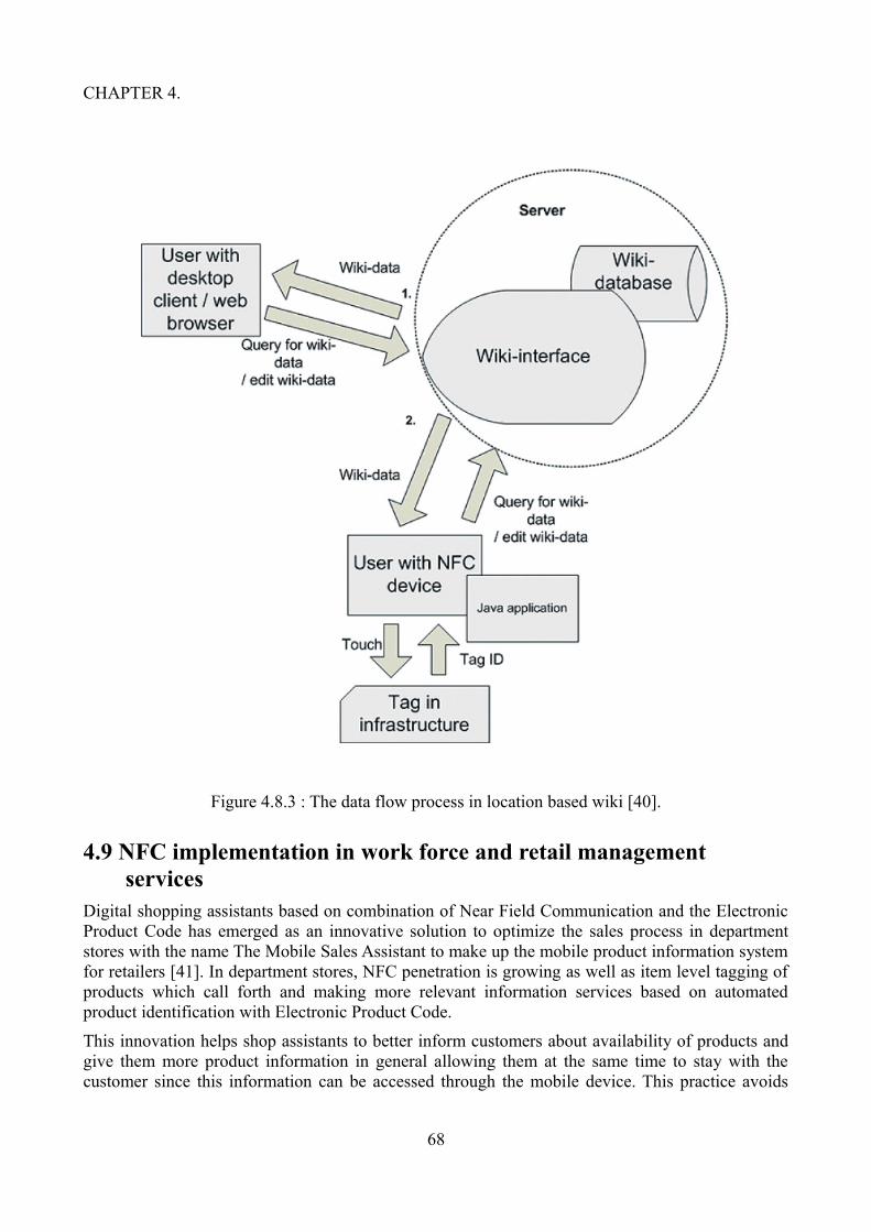
CHAPTER 4.
Figure 4.8.3 : The data flow process in location based wiki [40].
4.9 NFC implementation in work force and retail management services
Digital shopping assistants based on combination of Near Field Communication and the Electronic Product Code has emerged as an innovative solution to optimize the sales process in department stores with the name The Mobile Sales Assistant to make up the mobile product information system for retailers [41]. In department stores, NFC penetration is growing as well as item level tagging of products which call forth and making more relevant information services based on automated product identification with Electronic Product Code.
This innovation helps shop assistants to better inform customers about availability of products and give them more product information in general allowing them at the same time to stay with the customer since this information can be accessed through the mobile device. This practice avoids
68

CHAPTER 4.
long waiting times for the customer and increases customer satisfaction and potentially sales. On of the most common problems that customers often encounter in clothing department stores are out of stock occurrences as well as misplaced items or late replenishment. Customers also often search and inquire about the availability of items in the right size, cut or color. This demands time consuming processes for the shop assistants increasing their workload in conducting store operations. In cases like a customer founded an interesting item but can not find the right size or color needs shop assistant's help. While the customer has to wait for the shop assistant during the time he/she is looking for the wanted item physically on the shelves or in a backstore or alternatively using a personal computer to find information about availability of the wanted item, customers can become impatient and sometimes leave the store, affecting customer satisfaction, probably decrease in customer loyalty and even complete customer lost. As a result, potential sales may get lost.
The Mobile Sales Assistant is just for these kind of situations, providing practical and efficient solution. It is a NFC based mobile information system aiming to improve the quality of Point of Sale transactions by enabling shop assistants to check the availability and stock information of products directly with an NFC enabled mobile devices. During the checking process, the shop assistant touches the NFC tagged label of the wanted item or of a similar item or the shelf with the NFC enabled mobile device, information about availability of the wanted item and related products, such as other sizes or colors is retrieved from the company's Enterprise Resource Planning system and shown on the mobile device display. This in turn results in a situation where shop assistant can very quickly inform the customer about availability of the wanted item, staying all the time with the customer and finding single items rapidly and most importantly saving valuable time of the staff. In the further mature version of using the Mobile Sales Assistant, customer uses the application with his/her own mobile device and can easily check for availability of products without any assistance.
Main focus of the Mobile Sales Assistant is department stores of clothing retailers. There are three building blocks of software in the implementation: A server application, a client application on the NFC enabled mobile phone and product labels with NFC tags on which the Electronic Product Code is stored. The server application of the Mobile Sales Assistant is a web application consisting of standard web server and a data backend connected to a gateway server which gets its data from the company's Enterprise Resource Planning system. The client application is implemented in J2ME working on all mobile devices which implement the Contactless Communication API. The tagged products use Electronic Product Code format of serialized Global Trade Identification Number (SGTIN) in 96 bit format which is stored in Unique Resource Identifier format in an NFC Data Exchange Format message on the RFID tag, according to the NFC Forum standard specification Record Type Definition for URIs.
As the user touches the NFC tag attached to the product with the NFC enabled mobile device, the Mobile Sales Assistant client application on the mobile phone extracts the Electronic Product Code from the scanned NDEF message and builds a URI for a web resource with the company and product identifying part Global Trade Identification Number of the Electronic Product Code as a parameter. Then, it opens the mobile phone's web browser with this URI. The corresponding resource from the server application is rendered through the HTTP GET request from the server application. Information about the product's availability is then displayed on the mobile client's device display. Detailed information about the product and related products can be accessed via hypertext references. Figure 4.9 illustrates the Mobile Sales Assistant system.
69

CHAPTER 4.
Figure 4.9 : Mobile Sales Assistant system [41].
An other research [42] deals with the problems of sales data management system of chain enterprises, with the issues of high cost, low security, and poor performance of real-time. The data collected during the business activities of chain enterprises is huge and processing and exploiting the collected data inorder to benefit from it from the perspective of the market understanding capacity, market management capacity and market adaptability of the enterprises is very important. Despite of the efforts to improve sales data management issues through the data analysis and data management methods, there are deficiencies in the traditional data management methods, such as high cost of the sales outlets, lack of security and poor performance of real-time for the sales data mainly transmit through the internet and is limited to the network bandwidth. Near Field Communication technology provides effective solution for the problem of existing shortcomings of sales data management in chain enterprises.
The solution for the chain business sales data management system depend on the sales data management and other advantages such as convenient features, security and real-time functionalities of NFC enabled devices. The components of the system are NFC tags carrying information, NFC enabled devices, wireless data transmission network and database management server. The products are equipped with the NFC tags which are used to identify target objects and storing the relevant information of identified targets such as the product name, model, production date, price and other valuable information and they are placed in the corresponding location. Each NFC tag has a unique coding and corresponding product information and optionally secured with the encryption to prevent other reader and writer equipment to change the information in the tags. The sales staff read and collect the information in the NFC tags according to the authority granted
70

CHAPTER 4.
via NFC enabled devices and as a result products name, type, price and other information can be displayed on the mobile device and collected information processed either locally or sent through the internet for further data processing to the database in the backend system. Customer transactions information also saved in the database management server in backend for further processing.
The sales data transfer between NFC enabled mobile devices and sales database management server takes place through the wireless public network. For the importance of security, when transmitting the data will be encrypted by the safety components of NFC mobile devices and only the recipient can decrypt the data which also greatly enhances the security of enterprises data transmission by wireless network. The wireless network security is assured with the fast developing security technologies such as login authentication, encryption algorithm and the Advanced Encryption Standard AES. These technologies help securing highly sensitive enterprise information such as enterprises operation data, customer information as well as ensuring point-to-point security during enterprise data transmission through wireless network. In the backend system user authority and authentication and sales data are managed by the data management server, allowing enterprises users to access database server management systems in any location by the NFC enabled mobile devices and operate the product data, sales data and financial data in corresponding areas according to the authority granted.
Advantages brought by NFC technology to the sales data management are numerous. NFC technology is simple, convenient and low cost eliminating the need for PC sales terminals and preventing the poor performance of real-time issues caused by limited network bandwidth in traditional sales data collection method.
4.10 NFC implementation in healthcareUtilization of ubiquitous computing environment in alzheimer's patients day-care program is very vital. During demanding day-care, due to the fact that assistants do not wish to have their attention distracted from care they have neither time to supervise patients’ records nor to handle other kind of required information management routines. It is essential in this sense to transform the technology into such form where it is invisible, embedded, present whenever we need it, enabled by simple interactions, attuned to all our senses and adaptive to users and contexts. Even though effective exploitation of computer power has clearly positive impact on any productive work environment, computers are not well integrated into care environments. Most of the complains from staff in such demanding care work are about the difficulties of using healthcare applications. Majority of time of workers in this kind of context is taken up with managing patients’ information. The valuable part of the work for the staff is used for the routines even accomplished through the computers which could otherwise be used for caring, so technological adaptability seems to be needed towards solving this problem, by reducing that part of routine work. It is very important in organising the work environment to visualize the information especially in assisted contexts.
Research work [43] proposes use of NFC enabled mobile devices for care and technological adaptability as a complement in the treatment of the disease in an Alzheimer day center. NFC technology enables care assistants to manage patient information easily, preventing their attention being distracted and concentrate only on the patients. NFC technology requires from assistants only to touch tags on patients or in the environment. Apart from this care assistants are ask to put marks into the corresponding box on the incident forms.
In alzheimer day center, care environment operates for a few hours a day, from in the morning until after lunch. During their stay, patients carry out a few activities, while being cared for by assistants.
71
CHAPTER 4.
Families of the patients respite during the time they are in this care center from otherwise continuous attention. When performing activities, patients are placed into different rooms in small groups. Patients are collected by the daily transport service and after they are brought to the center, they have their breakfast together with other patients. After that daily activities begin. Daily different activities include Rehabilitation/Physiotherapy where the aim is to observe patients and promote their healty physical well being along with to know about recent injures as well as information about patient profiles and the physician’s recommendations. Therapy where the aim is to reinforce the memory by recognition of relatives and objects. Handwork (Occupational Therapy) where the aim is while doing some handwork, organising the sitting order of the patients with a special attention who they are sitting next to, inorder to promote proper development through the affinities. Visual where the aim is let the patients watch films and documentaries and monitor them easly. This enables the staff to prepare week's information, so as to draw up the recommendations for the families for the weekend. Lunch where the aim is to monitore the behavior at lunch, the menu, refusing to eat, affinities with other patients, fights and so on which are important aspects in the day-to-day life of the center.
Use of NFC technology to support the environment where these activities take place, brings the solutions to the problems mentioned before and facilitate the work of assistants in alzheimer day center. Solution considers two environments: the day center and the home. In these environments NFC tags are placed on the patients, places, devices, processes and interaction displays. Configuration of NFC tags include an identification that serves to control the patient, place or device. The structure of the tag defines tag content. The media access control address of the server is also stored on the NFC tag to ensure the communication and to obtain immediate access in case it is needed through the NFC enabled mobile device. User access is controlled with the authorization part of the NFC tag. The remaining part of the NFC tag is related to the asociated services such as default, incidences, orientation, recognition (object or people), open door, location and interaction which can be run by touching tags with NFC enabled mobile devices. Bluetooth connectivity is also able to activate these services. Functionality of these services can be general and fixed such as opening a door or dynamic and customized such as writing patients’ incidents or showing family pictures on a display. In some tagged exercises of therapy recognizing family members or objects is done by a single touch with the NFC enabled mobile device. In using the tagged interaction display, assistants can interact with the information of each patient via NFC tags placed near the display, using family photos or videos as a support for refreshing patients’ memory.
The basic components of the system composed of NFC enabled mobile devices, NFC tags and a server to store and process the patient records, recommendations to families and for filtering information to physicians. NFC tags are placed on the walls of the rooms indicating the start or finish of a session, the opening of a door, location, orientation and so on.
In the crucial task of information recording of the assistants via easy interaction, set of forms requiring only the checking of lines referring to the everyday behavior in each activity are used with a special care not to distract the attention of patients. The aim is to receive natural interaction of the patient, so patient incidents should be transformed. The easiest way to do this compared to writing the incidents in a note book is information transformation through forms filled by checking the corresponding lines which are the incidents that are stored in patients’ NFC tags.
Collected information of the incidences are very important because in the method used, they are interpreted, codified and then converted into recommendations for the activities that follow for the care assistants. After grouping the recommendations, they are offered also to families and elaborated versions are given to physicians. In the typical example of a patient day centre routine, the bus arrives at patients house in the morning. An assistant exchange ideas and talks about the
72

CHAPTER 4.
events at home about the patient with the relatives, for example about an injury to the patient's left hand. They also exchange information by touching their NFC enabled mobile devices. After arriving at the alzheimer day center, a nurse reads patient's NFC tag by the NFC enabled device and observe the information about the injury on the device display. Nurse after examining patient's hand, provides the necessary treatment measures. This information is also stored in the server. By touching with the NFC enabled mobile device to the patient's NFC tags nurse receives the schedule and take the patient to the therapy room. An other assistant receiving the patient in therapy room reads patient's NFC tag and transmits the location information to the server and checks patient's schedule. The therapy begins with the conversation about the time at home and question's about the family such as names of the relatives, their ages and so on. When the patient has difficulties in remembering his/her spouse's name or age the assistant touches with the NFC enabled mobile device to the display control NFC tag and then patient's NFC tag which results in appearance of some exercises about patient's family and objects on the display. Memory therapy exercises aided by photos and videos help the patient recognize the family members. When the patient moves to the physiotherapy room, the assistant reads patient's NFC tag and decides to skip exercises and recommends him to sit down for this activity. At lunch, the care assistant observes that there are no problems with the menu for the patient. When the patient taken to home relatives are informed about the medical treatment applied to patient's left hand in the day care center.
An other research in the clinical data acquisition based on NFC technology has given encouraging results in the feasiblity of the use of this new technology in clinical research [44]. Clinical data collection has evolved from the paper-based processes to the computerized systems and use of special software programs such as electronic data capture (EDC) system which is a web-based system to collect clinical research data particularly for late-phase (phase III-IV) studies and pharmacovigilance and post-market safety surveillance. During the process of clinical data collection, physicians, nurses, and investigators are entered the data manually through the graphical user interface which could either be a separately installed client software application or a common web browser to view and edit the forms. The process also included real time data verification for plausibility while data is entered and stored centrally to be analysed further. Even though transition to electronic data collection from the paper-based process is a crucial improvement, technological tuning to optimize clinical data acquisition still continues. Wireless network connection internet access exploiting also wireless local area network and mobile devices is another major leap in the process allowing to enter clinical data at the point of care while at the same time giving chance to talk to the medical professionals.
Most of the data collected in the clinical trial are measurement values of the medical devices such as blood pressure meters, body weights scales, blood glucose meters, thermometers, and so on. The client data measured this way are read from the displays of these devices and values are written into the electronic data capture forms. Client data could be read in automatically by means of electronic data transmission, either with wired or wireless technology. This in turn would provide significant improvement in the data acquisition process both by simplifying the process and also reducing the need for plausibility checks regarding the measurement values. Utilization of NFC technology in this respect offers the suitable option for the solution in terms of usability and feasibility regarding to cabled or wireless connection properties of interfaces of the alternative technologies between the measurement devices and the client devices for clinical applications. Moreover, Near Field Communication technology integrated into the mobile devices acts as a gateway in acquiring medical measurement data and other relevant parameters from the point-of-care devices and forwarding them to the electronic data capture server system. Building a consistent system for acquiring research data within a clinical environment needed which would meet the required
73

CHAPTER 4.
features such as portable usage to enable data acquisition at the point of care, easy to use handling, on/offline data acquisition, identification management regarding multiple centres, investigators, patients and devices, web-based central data storage and a system independent from the clinical IT system.
The system which is build on the most advanced stage of a technology for the time, has four elements: a web-based electronic data capture server system to collect the clinical research data, a cardiovascular monitoring device with NFC capabilities, a NFC-enabled mobile device acting as a gateway and RFID tags for authentication and identification.
Figure 4.10.1 : The web frontend of the system in view mode [44].
In order to edit and view the stored data in the database, authorized users of the system accessed the system through the secure https connection. The database contained detailed medical information such as user dependent patient lists, patient specific examination lists, anamnesis data of body mass and body height, data on prescribed medication and detailed measurement views as well as
74

CHAPTER 4.
information acquired by the server side calculated values and graphical representations. Figure 4.10.1 illustrates the web frontend of the system in view mode.
The NFC enabled mobile client device with a specific java application installed on it, is used to securely receive the clinical research data directly acquired at the point of care. NFC client device allowed automatic and easy process of the user authentication, fetching the data from the measurement devices, linking them with the corresponding patient ID, and uploading the record to the electronic data capture system. In case of connection failures the application stored all data within a local database which is encrypted through the user card and uploaded them to the database in the electronic data capture server in the course of the next session.
Patients and measurements taken are related to each other by identifying each patient with an RFID tag which has an unique identification number. This ID is stored within the secured area of a RFID label according to the ISO 14443A standard and attached to an item unambiguously related to the patient such as wristband or chart. Touching this card with the NFC enabled mobile device authenticates the user who performes the measurement and starts the application to perform the wireless data acquisition procedure. In practice, NFC enabled mobile device guides the user through the specific sequence of screen prompts such as prompting the user to touch the medical device and the patient ID tag after that starting to transmit the respective record and indicating on the display until the data is successfully synchronized with the electronic data capture system or a timeout occurred. Figure 4.10.2 illustrates the data acquisition and indexing process.
Figure 4.10.2 : The data acquisition and indexing process [44].
75

CHAPTER 5.
Chapter 5
Technical features required by the applicationsThis chapter describes the different features of the three specific NFC tags MIFARE Ultralight , MIFARE Ultralight C and the MIFARE DESFire EV1 which are highlighted throughout the thesis and the relation of these features in deciding which NFC tag to choose for a specific application to be designed.
5.1 MIFARE UltralightThe MIFARE Ultralight is low-cost, inexpensive card having only 512 bits of memory (i.e. 64 bytes) and basic security features such as one-time-programmable (OTP) bits and a write-lock feature to prevent re-writing of memory pages, on the other side having no encryption to enhance the security like in other more sophisticated MIFARE cards [45]. For those systems integrators whose main priority is to minimize the costs would choose this card moving the security efforts in the backend system. For such systems working with readers with a permanent link to the backend, by using earlier mentioned security features of one-time-programmable (OTP) bits and a write-lock memory areas and transaction counters, relatively efficient efforts can be employed to make cloned cards useless or allow the backend system to detect a fraudulent card and put it on a blacklist. Whereas for systems working with readers lacking a permanent link to the backend, real-time checks are not possible and blacklists cannot be updated as frequently.
On the basis of these security issues, key applications suitable for MIFARE Ultralight cards are limited-use, disposable tickets. Examples for such cards can be found in public transports such as smart paper single trip tickets, multiple trip tickets which bring out a solution to help transport operators to reduce fraud and the circulation of cash within the system, loyalty cards, tourist weekend passes, single event ticketing such as games and concerts in stadiums, exhibitions and leisure parks and day passes at big events. MIFARE Ultralight cards are the ideal replacement for conventional ticketing solutions such as paper tickets, magnetic-stripe tickets or coins. Moreover, mechanical and electronical specifications of MIFARE Ultralight are tailored to meet the requirements of paper ticket manufacturers. One of the biggest advantages MIFARE Ultralight card system provides is its easiness to be integrated into existing systems in a way that even standard paper ticket vending equipment can be upgraded for example by fitting a simple contactless reader for ticket initialization, reducing the system installation and maintenance costs.
5.2 MIFARE Ultralight CA vital security flaw in MIFARE Ultralight cards is pointed out by security consultancy Intrepidusgroup [47] in September 2012 in Amsterdam and demonstrated how MIFARE Ultralight travel cards used in the public transportation of the two cities namely New Jersey and San Francisco can be abused. Demonstration showed the fact, how it is possible to reset the card balance in
76

CHAPTER 5.
MIFARE Ultralight travel card to get a free travel right by using an Android application in NFC enabled Nexus S phone. During the trail, the content of the ten trip MIFARE Ultralight travel card was read by the NFC enabled Nexus S phone's application. More specifically the application read all the data in memory pages from 4 to 15 as well as the UID from the card and stored the information in the phone's memory. After the 10 trips on card have been used up, it was possible to reset the card balance by writing the data back to the card from the phone's application by touching the card to the NFC enabled Nexus S phone. It was also remarkable that the transit systems used in the trail left the One Time Programmable OTP bits in memory page 3 unchanged, which would have secure the use of the card by acting as a one way counter, only to a limited number of times. Even though this was not a direct attack on the chip, MIFARE card producer NXP have responded to this by introducing the MIFARE Ultralight C in 2008 with Triple DES encryption protection.
MIFARE Ultralight C is the first smart card IC in the low cost segment but with bigger memory capacity of 1536 bits (192 bytes) and backwards compatibility to MIFARE Ultralight in addition provides the benefits of an Triple DES open cryptography for limited use applications, providing for example an effective countermeasure against cloning [46]. The key applications include single trip tickets in public transportation, loyalty cards, day passes at big events replacing conventional ticketing solutions of paper tickets, magnetic-stripe tickets or coins as well as smart poster tags in NFC applications.
The command set of MIFARE Ultralight C is compatible with MIFARE Ultralight, on the other hand the authentication commands are the same as the authentication commands in MIFARE DESFire EV1, giving MIFARE Ultralight C an advantage of compatibility with the existing MIFARE infrastructure and easy integration in current contactless solutions. Capability of easy integration into the existing systems helping to reduce the system installation and maintenance costs, reduced cash handling and increased fraud preventation are additional values MIFARE Ultralight C brings to the system.
5.3 MIFARE DESFire EV1MIFARE DESFire EV1 is a secure, scalable and flexible multi-application, high speed card [48]. Through scalability it is possible to scale the features such as security, communication speed, and memory requirements. Flexibity makes the MIFARE DESFire EV1 unique in the sense that it allows to define the required file system, the size of the file and the communication type. MIFARE DESFire card has been continously extended and updated according to the changing needs and requirements of especially security and to keep the level of the most advanced stage of a technology since it is first introduced with the basic applications and installations, later on whenever needed a new product or new evolution with the extended features, the system was able to adapt to that new feature making system always up to date. The first product release was in 2002 with MIFARE DESFire EV0, that is evolution 0 with the memory size 4KB, then in 2008 with MIFARE DESFire EV1 wich is evolution 1, included regular maintenance and it was backward compatible with evolution 0 DESFire EV0 and on the top added 3K3DES and AES128 with three memory capasity options with 2KB, 4KB and 8KB and also the feature of configurable random ID to protect the privacy as well as to protect the tracking based on the fixed ID on the wallet application. The released version 5 in 2011 included two higher capacitance chip having two versions one is with 70 pF and other is with only 17 pF, the optimization and the regular maintenance were provided to make the product more robust against some non AES supporting property protocol.
Even though there have been continuously new areas discovered where MIFARE DESFire EV1 applications are used, some important application areas where MIFARE DESFire EV1 applications
77

CHAPTER 5.
can be a unique choice highlighted.
Loyalty programs: Through the loyalty programs customer engagement can be increased with the easy usability of the card. While cardholders earn points to get discounts and advantages, loyalty points are securely stored on the card for offline earning and spending. Examples for such loyalty cards are Virgin air frequent flyer card and German blood donor card.
Public transport programs: This actually is the prime market for MIFARE DESFire EV1 applications used widely in many cities and countries for public transportation. Because it is flexible, it is possible to design the price system according to choice and put multiple applications in one card such as transport ticket, credits or authority for printing, buying a cup of coffee. MIFARE DESFire EV1 provides fast, reliable and secure access to public transportation. It is suitable also as prepaid and season cards and proven and tested in nationwide systems. Examples of such cards are San Francisco Clipper card, London Oyster card and also cards used in cities of Madrid, Bangkok, Delhi, Bombay and Dubai.
NFC Tags: Can carry NDEF messages according to NFC Forum standards for MIFARE DESFire EV1 and are convenient for NFC interconnections and smart information sharing, requiring for interactions no more action than a simple touch. Examples of such tags are rapid growing popularity of smart posters, advertising in stores and access to content download.
Micro Payment: Micropayment includes features such as mobile wallet, contactless payment and cashless payment. Because of the easiness, speed and security of use very suitable for closed loop micro payments, fast cashless transactions, suitable for shops near subway stations, canteen payments or loyalty cards. Micropayment is used in Indonesian theme parks and in Vietin Bank.
Access Management: Another prime application area is the access management with secure access to buildings, supported by all leading system integrators and ready for multi-application such as canteen payment and parking access. Companies such as General Motors, Nestle, EU comission, Australien Department of Defence are using the MIFARE DESFire EV1 for the access control.
Student card: There are many universities using MIFARE DESFire EV1 for their student cards and for the library cards as reliable multi-application solution. It is also used for physical access to the university and students home buildings as well as micropayment for student restaurants and for logical access to PCs and services. European Campus Card Association uses MIFARE DESFire EV1 in this way.
78

CHAPTER 6.
Chapter 6
Implementation experimentsThis chapter describes the programming work of the thesis which was necessary to understand both the NFC and comprehend functionalities of the smart card technology.
6.1 Tools and technologiesFor the programming tasks, a lap-top computer with the Windows operating system of version 8.1 is used. As the programming devolopment environment an integrated development environment (IDE) of Eclipse version 3.7.1 for Java is chosen. Additionally, a SCL011 Multi-protocol 13.56MHz contactless reader connected to the computer for reading and writing the smart cards along with the Google Asus Nexus 7 tablet computer with Android 4.4 KitKat mobile operating system and NFCInfoTag, TagInfo and TagWriter applications installed, Google Nexus S cellular phone with Android 4.1.2 Jelly Bean mobile operating system with the NFCInfoTag, TagInfo and TagWriter applications installed are used.
The basic framework of the programming task is based on the event ticketing programming Also provided documents MFOICU1 Functional specification MIFARE Ultralight, MF1ICS70 Functional specification, NFC Forum Type 2 Tag Operation Specification, NTAG203F NFC Forum Type 2 Tag compliant IC with 144 bytes user memory and field detection and Mifare DESFire Contactless Multi-Application IC with DES and 3DES Security MF3 IC D40 are extensively used. However provided documents were inadequate much of the time and quite often intensive internet search for the required information was necessary.
79

CHAPTER 6.
Figure 6.1: Photo displaying test environment: PC, card reader, card on the card reader and different NFC tags.
6.2 Programming task and experiments with Mifare Ultralight cardThe programming tasks for the Mifare Ultralight card included the realisation of the following menu items: ”dump” for displaying the memory content of the card, ”format” for formatting and clearing out the content of the card, ”issue” for issuing a new ticket, ”use” for using the tickect by reading, ”writeurl”, ”writesms”, ”writewwws”, ”ndefwwws” and ”writetext” for Smart Poster or information tag messages and cardcopy for testing the security of the Mifare Ultralight card.
The communication between PCD (reader) and PICC (tag) starts with the ATR (Answer-To-Reset) command. This is the command that PCD sends to PICC for identification purposes. By the help of this command reader identifies the type of the card, in this case, whether it is a Mifare Ultralight or a Mifare DESFire EV1 card.
For the Mifare Ultralight card, first task was to write a ticketing application. In ticketing application the card needed to be formatted inorder to be used as a tickect. Format method erase the card memory. Process fails if any of the pages is locked.
80

CHAPTER 6.
6.2.1 NDEF messages
The read and write operations of the cards are done by the test device Google Nexus 7 tablet computer, with the NFCInfoTag, TagInfo and TagWriter applications installed. The idea behind this was the thought that already tested and widely used applications function correctly. Data produced by the NFCInfoTag, TagInfo and TagWriter applications of the test device studied carefully and efforts was consumed to produce the identical data with the own software code. The validity of the own software code for the write command checked after writing to the card by reading the card with the NFCInfoTag and TagInfo applications of the test device and also the contents of the programme were studied by the help of the same applications. Own software code for the methods writeurl, writesms, writewwws, ndefwwws and writetext was produced with the help of these informations. Every development phase of the own software code was checked with the available, installed applications of the test device Google Nexus 7 tablet computer.
6.2.2 Ticket application with Mifare Ultralight
Ticket application included programmable time stamp and number of single uses. When issuing the ticket, each write command to the card required calculation of writable memory places and additionally calculation of memory spaces for the Message Authentication Code (MAC) for calculating the checksum. The seven first byte of each memory place of the card is reserved for card UID.
The card can be reused by rewriting the travel information. If desired, the use of the card can be restricted by bringing into use OTP (One Time Programmable) bits, total size of four bytes 32 bits. Each use of the card would change the state of one bit of the One Time Programmable bits. By this way the usage of the the travel card can be confined with 32 single uses. Additionally by using the corresponding locking bit each page in the memory place from 0x03 to 0x0E may be locked individually to prevent further write access. For example, expiry time (not tested) could be locked by this way.
Single use of the ticket has a limit for 32 uses as four OTP bytes are used as incremental counter after each single use of the ticket. This measurement ensured that the ticket could not be copied after it is used for 32 times. Each use of single ticket decremented the ”remaining uses” by one. The new updated or changed value of remaining uses had to be written to the memory by a new calculation of writable memory places and following new calculation of check sum of Message Authentication Code.
The method ”validate” processes and controls the validation of the ticket by checking expiry time and decrementing number of remaining uses after each use of the ticket.
6.2.3 Deficiency in the security of Mifare Ultralight ticket
One of the menu items for Mifare Ultralight ticket application as mentioned above is cardcopy and its relating method for testing the security of Mifare Ultralight ticket. With the help of this method working proof of cloning the daily ticket which is still in use in public transportation to a clon card is achieved. Running this method enables to copy the content of the Mifare Ultralight type daily ticket to the clon card. Clon card can then be used in public transportation as a normal travel card. When the time of the travel card expires, cloning process can be repeated. In fact this process can be repeated as many times as required or the content of such ticket can be cloned to many other clon cards at a time.
81

CHAPTER 6.
6.2.4 Simultaneous handling of multiple cards
Despite of exhaustive trials to read multiple cards at a time turned out to be over challenging because the smart card reader did not recognize more than a card at a time. Simultaneous reading or writing operations of multiple cards require lower level operations like REQA , WUPA, SELECT, HALT which are not available with the SCL011 Multi-protocol contactless reader. Only read or write operations for a single card were possible. When trials were performed using two or more cards, reader tend to read uncertainly the card which was closer.
6.3 Programming task and experiments with Mifare DESFire EV1 card
The programming tasks for the Mifare DESFire EV1 card included the realisation of the following menu items: ”EV1read” for displaying the memory content of the card, ”EV1format” for formatting the card, ”EV1issue” for issuing a new ticket, ”EV1use” for using the tickect by reading, ”EV1write” for writing to the card, ”EV1readtext”, ”EV1writesms”, ”EV1readsms”, ”EV1writetext” for Smart Poster or information tag messages and ”EV1clean” for eraesing the content of the card without formating it.
The communication between PCD (reader) and PICC (tag) through the ATR (Answer-To-Reset) command identifies the Mifare DESFire EV1 card when it is placed on the reader. Since the Mifare DESFire EV1 card is very different in its properties from the Mifare Ultralight card completely new basic operations are needed.
In the beginning for practical reasons best solution was proved to be to explore the details of the application's code and structure of files by the relevant applications installed to the tablet. The aim was to produce similar correctly working programming code for applications and files.
Applications of the test device tablet Google Nexus 7 were used to examine applications and files of the NDEF messages in detail.
Available documents were inadequate most of the time and different challanges encountered in writing the software code for DESFire EV1 card operations, extensive internet search was necessarry. Depending on the file access rights, accessing to some files required a preceding authentication. Formatting the card required also preceding authentication. At the beginning formatting is done by using the applications on the tablet before own formatting application code was written which was quite challenging.
6.3.1 Ticket application with Mifare DESFire EV1
Also ticketing application code is written for Mifare DESFire EV1 card. In Mifare DESFire EV1 card application number and file number can be choosen freely and the file includes variables the expiry time and number of uses. The use of the variables is similar to the Ultralight card. The only difference is that in Mifare Ultralight card the variables are on memory places whereas in Mifare DESFire EV1 card the variables are in the files which are in applications.
82

CHAPTER 7.
Chapter 7
Discussion of NFC application design issuesThis chapter discusses the basic concerns and feasibility of NFC application design issues. Different NFC applications have different requirements. On the basis of end use purpose, some applications may emphasises the security, or the technical capability whereas for others price can be more important. The trade off between security and price and psyical properties of NFC devices such as memory structure and capasity and security features are strategical questions in choosing the wright tools in designing different NFC applications. The last sections present briefly other smart cards and applications including JavaCards and bank cards.
7.1 NFC tag design and applicationsIn designing a NFC application, analysis for the main objective should be carefully made. The designing and production considerations of the NFC tags are vast, but the main intention is to manufacture the NFC tags with very low cost in very large quantities without compromising from the performance. The NFC Tag 2 Type tags MIFARE Ultralight and MIFARE Ultralight C which are based on ISO14443A standard and the NFC Tag 4 Type MIFARE DESFire EV1 based on ISO14443A and B standards are in this respect have different properties to be taken into consideration. Table 7.1 illustrates the comparative properties of these three NFC tags.
Type 2 Tag Type 4 Tag
Compatible products MIFARE Ultralight, MIFARE Ultralight C
MIFARE DESFire EV1
Memory capacity 48 Bytes / 144 Bytes 4 KB / 32 KB
Unit price Low Medium / High
Data access Read/Write or Read-Only Read/Write or Read-Only
Communication speed 106 kbit/s 106 kbit/s and 424 kbit/s
Table 7.1: Comparative properties of MIFARE Ultralight, MIFARE Ultralight C and MIFARE DESFire EV1 tags.
The memory size of the NFC tag is significantly important in regards of the requirements of the different solutions and their performances in the end-use. If the aim for example, is to encode a simple 126-character web-link to the tag, tag memory size of 1152 bits/144 bytes might be sufficient. For encoding shorter web links of up to 36 characters, tag memory size of with 384
83

CHAPTER 7.
bits/48 bytes might be suitable. In the case of encoding business cards in Vcard format, tags with the memory size 1 kB might be appropriate.
Data transfer rate of the NFC tag is also an important feature for the end-use. Depending on the objectives during usage, if the NFC tag can only transfer data at a slow rate then there is a risk that all the data may not be transferred in time ending up in a poor level of reliability. The user who is not very familiar with the technology and keep re-trying to successfully transfer the data will easily be frustrated and be turned off from using the system.
Size of the memory is related to the size of the integrated circuit of the choosen NFC tag which in turn effects the cost of the tag. A smaller integrated circuit results in lower cost, on the other hand, however the required integrated circuit complexity is an other factor. Well defined rigorous strategy and plan is needed according to the end-use requirements of the application as to which NFC tag type to choose with which kind of build-in properties. The issue of cost-functionality quality property is important especially if the aim is to use mass volume of tags for the application.
Security is one big and important factor related to the structure of the integrated circuit in the process of deciding for the optimally suitable tag for the application. There is a trade off between the price and the security properties of the NFC tags and applications. In the design strategy phase, it is important to consider the determinants from the point of view of the end-use of the final product. Is the trade off between the price and the security properties in favor of the price or security in the case of the application to be designed? Is less security acceptable in favor of the price especially if the application is used in mass volume of NFC tags? Earlier it is mentioned that for public transportation MIFARE Ultralight and MIFARE Ultralight C tags are used which have limited security properties to prevent fraud and cloning with a limited success.
There seems to be endless race between the manufacturers of the software products and the hackers. Section 5.2 in chapter 5 discussed the vital security flaw in MIFARE Ultralight tags and how it is lead to the abuse of the smart card tickets in public transportation in the cities of New Jersey and San Francisco. Also in section 3.3 in chapter 3 the security flaw in the DESFire MF3ICD40 of NFC Tag 4 Type which had enhanced security through the use of Triple DES 112-bit key for authentication and data encryption is mentioned and how the security of DESFire MF3ICD40 was broken in 2011 by the power analysis attack through which the secret key was able to be retrieved. Security concerns might be a crucial reason to explain why technology producers of the field are not very eager to disclose the technological information of these products.
In each NFC application design the same question will rise: is it the price or security? How to balance them both in the optimal way? Technological improvements on the field which reduces the price of the technically advanced tags with enhanced security will probably contribute in finding the solution by increasing the volume of available options.
7.2 Other smart cardsSmart cards are classified into different groups according to their properties such as memory cards and microprocessor cards. The card access mechanism devides the smart cards into yet another group of contact cards and contactless cards. First smart cards produced were memory cards without a microprocessor containing a memory chip, nonprogrammable logic and not reusable which were in this sense not smart cards. The data processing of the card is performed through a simple circuit which is capable of executing very limited preprogrammed instructions. Data security of these cards are provided by protected memory or secure logic.
Microprocessor cards on the other hand has a processor, increased security, enhanced computational
84
CHAPTER 7.
power and multifunctionality which are also customizable to integrate one or several different applications. The access and the data processing is controlled by the processor through the passwords, encryptions and instructions from the external applications.
Contact cards must be inserted into the mechanical reader in the correct way so that the communication with the outside world can be provided through the eight contact points of serial communication interface. Whereas the transaction with contactless cards takes place by only holding the card in the near proximity of the reader device giving considerable promptness and flexibilty.
7.2.1 Programmable contactless smart cards and tags
Programmable contactless smart card and MIFARE DESFire EV1 tag have some similar features. They are both passive devices powered through the electromagnetic field generated by the card reader device when the card is in close proximity of the reader. Both programmable contactless card and MIFARE DESFire EV1 tag can integrate multiple applications in a card and are used for data storage. Programmable contactless smart card has far more dynamic computational power functionality operating with a high-level programming languages due to its processor. MIFARE DESFire EV1 tag has very limited pre-defined operations and functions such as retrieving NDEF messages.
7.2.2 JavaCards
The Java card is a resource-constrained, programmable contactless smart card which is able to run applications written for the Java card platform [49]. Due to the resource-constrained structure, only a subset of the Java language features are supported causing Java card virtual machine to support corresponding features which are required by the language subset. These features however provide the Java card with the properties of security, portability and robustness. Architecture of a Java card has three components [50]:
The Java Card Virtual Machine(JCVM): It defines a subset of the Java programming language and virtual machine definition for smart card applications.
The Java Card Runtime Environment(JCRE): It determines clear separation between the smart card system and the applications. Describes Java card runtime behavior: memory management, application management and other runtime features.
The Java Card Application Programming Interface (API): It defines the set of core and extension Java packages and classes for programming smart card application.
Figure 7.2.2 illustrates the architecture of a Java card application and its relation with other system components.
85

CHAPTER 7.
Figure 7.2.2: Architecture of a Java Card Application and its interaction and relation with reader-side and back-end elements[50].
7.2.3 Bank cards
Emergence of smart cards has had impact on the banking system and influenced the way they operate. Europay, MasterCard, and Visa (EVM) have together defined the global standard for credit and debit payment cards based on chip card technology which determines the processing of credit and debit card payments using a microprocessor chip embedded card. According to the EMV deployment figures published by EMVCo in May 2012, 45 per cent of all payment cards and 76 per cent of payment terminals used globally are based on EMV technology. There are over 1.5 billion EMV payment cards in circulation (up by 25% since 2011) and 21.9 million EMV terminals (up by 18% since 2011) [51]. EVM standarts have brought strict security measures for the smart cards such as two-factor authentication which provides unambiguous identification of users by means of the combination of two different components. This in turn, insures protection of data and value in the transactions executed across the internet. Customers of banks and credit card companies can securily use smart cards for fast electronic funds transfers over the internet. From the banking system point of view, use of smart cards this way reduces the costs substantially because through this, transactions that normally would require a bank employee's time and paperwork can be managed electronically by the customer with a smart card sparing also customer's time to go to the bank. The implementation of EMV within an NFC mobile device has also been defined which
86

CHAPTER 7.
considers the use of NFC enabled mobile device in contactless card emulation mode. Through this a NFC enabled mobile device can present EMV data over the contactless interface from an EMV compliant payment application that is stored in the mobile device. Both EMV and NFC support the same ISO/IEC 14443 standard contactless protocol.
87

CHAPTER 8.
Chapter 8
ConclusionsNear Field Communication is a novel and efficient technology for communications within short ranges, offering an intuitive and simple way to transfer data between electronic devices. It has already been leveraged in the existing ecosystem related to payments and contactless ticketing, which involves millions of users. NFC devices offer a diversity of functions such as to operate as a contactless smart card and as a medium to exchange data between various devices in the form of text, images and URLs simply by holding the passive NFC devices in the close proximity of the NFC readers. The mobile industry has been integrating the NFC technology especially into mobile commerce and businesses. This development is driven by the public's increasing dependence on smart mobile devices and the demand for new functionality in them. The phenomenon enables a means for the industry to conduct a variety of transactions using NFC technology integrated on mobile devices. The benefits and the potential uses of NFC technology will continue to create more inspiration for innovations in the field.
NFC Forum Type 2 Tags MIFARE Ultralight and MIFARE Ultralight C and NFC Forum Type 4 Tag MIFARE DESFire EV1 are widely used in different NFC applications. In this thesis, the different memory structures and the basic functionalities of these tags are studied through programming a contactless ticketing application. Writing the code to execute and examine the functionalities such as formatting the tag, issuing and using a ticket, creating NDEF messages, writing the URL to the tag, writing and reading SMS messages, writing and reading text messages along with the implementation of the security properties and getting familiar with the different use cases of each of these tags helped comprehend the technology in a broader sense.
NFC technology has run over the initial application areas of mobile payment and contactless ticketing. A wide range of new potential application areas can be achieved by combining the NFC tags with the positioning, communication and computing capability of sensors and other devices. Smart posters enable users to exploit the advantages of easily reading NDEF messages such as a web address for buying sports tickets including, as an additional possible service the transaction for reserving and buying the tickets, a timetable displayed at a bus stop and coupons inserted in a magazine advertisement. NFC is used as a key in access to homes, offices and hotel rooms. Other diverse application areas of the NFC technology include implementation in library services, in entertainment services, in social network services, in educational services, in location based services, in work force and retail management services and in healthcare.
The strongest implication of the diverse implementation and application areas of NFC technology is its potential ubiquitous character. Interoperability, multifunctionality, fast communication and transaction properties together with the integrability with the diverse devices and systems are prominent features of the potential ubiquitousness.
To our knowledge, such a broad study of the many applications of NFC technology has not been previously presented. Possible future work involves studying the NFC applications as parts of the
88

CHAPTER 8.
ubiquitous systems and implementing NFC applications in a ubiquitous computing system.
89

BIBLIOGRAPHY
Bibliography
[1] NFC Tags. A technical introduction, applications and products. Rev. 1.3 -1 December 2011.
[2] NFCIP-1: ISO/IEC 18092:2004, Information technology - Telecommunications and information exchange between systems – Near Field Communication – Interface and Protocol (NFCIP-1).
[3] Coskun, V., Ok, K., and Ozdenizci, B. Near Field Communication: From Theory to Practice. Wiley, February 2012.
[4] Introduction to NFC. Nokia Developer. Document created on 8 July 2011, Version 1.1
[5] NFC Forum. NFC Data Exchange Format (NDEF), July 2006.
[6] NFC Forum. Type 1 Tag Operation Specification, April 2011.
[7] NFC Forum. Type 2 Tag Operation Specification, May 2011.
[8] NFC Forum. Type 3 Tag Operation Specification, June 2011.
[9] NFC Forum. Type 4 Tag Operation Specification, June 2011.
[10] AN1303 MIFARE Ultralight as Type 2 Tag. Rev. 1.5 — 2 October 2012, 130315
[11] NFC Forum Type 2 Tag Operation Specification Technical Specification T2TOP 1.1 NFC ForumTM NFCForum-TS-Type-2-Tag_1.1 2011-05-31
[12] Oswald, D., and Paar, C. Breaking mifare desfire mf3icd40: Power analysis and templates in the real world.
[13] NXP Semiconductors. MF3ICDx21 41 81-MIFARE DESFire EV1 contactless multi-application IC-Product short data sheet-Rev. 3.1, December 2010. http://www.nxp.com/documents/short_data_sheet/MF3ICDX21_41_81_SDS.pdf. Accessed 28.8.2014.
[14] Daniel Andrade, Master's Thesis, Connecting NFC to the Cloud 2013.
[15] NFC Tags. A technical introduction, applications and products. Rev. 1.3-1 December 2011. White paper.
[16] NFC FORUM. NFC. NFC Data Exchange Format (NDEF). Technical Specification. NFC ForumTM, NDEF 1.0, NFCForum-TS-NDEF_1.0, 2006-07-24.
[17] NFC FORUM. URI Record Type Definition. Technical Specification. NFC ForumTM, RTD-URI 1.0, NFCForum-TS-RTD_URI_1.0, 2006-07-24.
[18] Busra Ozdenizci, Mohammed Alsadi, Kerem Ok, and Vedat Coskun. ”Classification of NFC Applications in Diverse Service Domains”. International Journal of Computer and Communication Engineering, Vol. 2, No. 5, September 2013. DOI:
90
BIBLIOGRAPHY
10.7763/IJCCE.2013.V2.260, pp. 614-620.
[19] Jie Shen, Xin-Chen Jiang. ”A Proposed Architecture for Building NFC Tag Services”. 2013 Sixth International Symposium on Computational Intelligence and Design, 978-0-7695-5079-4/13 $26.00 © 2013 IEEE, DOI 10.1109/ISCID.2013.126, pp. 48-52.
[20] U. Biader Ceipidor, C. M. Medaglia, A. Marino, M. Morena, S. Sposato, A.Moroni, P. DiRollo, M. La Morgia. ”Mobile Ticketing with NFC management for transport companies. Problems and solutions”. CATTID (Centre for Application of Teleservices and Technologies for Innovation in Digital world) Sapienza University of Rome, Italy. Computer Science Department - Sapienza University of Rome, Italy Scuola laD - University of Rome "Tor Vergata", pp. 1-6.
[21] Hongwei Du. ”NFC Technology: Today and Tomorrow”. International Journal of Future Computer and Communication, Vol. 2, No. 4, August 2013. DOI: 10.7763/IJFCC.2013.V2.183, pp. 351-354
[22] MF0ICU2 MIFARE Ultralight C, Rev. 3.2 - 19 May 2009, Product short data sheet, 171432, PUBLIC.
[23] Tuomo Tuikka & Minna Isomursu (eds.), ”Touch the Future with a Smart Touch, VTT RESEARCH NOTES 2492, ISBN 978-951-38-7306-6 (soft back ed.), ISSN 1235-0605 (soft back ed.), ISBN 978-951-38-7307-3 (URL: http://www.vtt.fi/publications/index.jsp), ISSN 1455-0865 (URL: http://www.vtt.fi/publications/index.jsp).
[24] NFC Forum Smart Posters (NFC Forum smart poster white paper). ”How to use NFC tags and readers to create interactive experiences that benefit both consumers and businesses”. April 2011. NFC Forum, Inc. 401 Edgewater Place, Suite 600, Wakefield, MA, USA 01880.
[25] NFC Forum. ”NFC in Public Transportation”. January 2011. NFC Forum, Inc. 401 Edgewater Place, Suite 600, Wakefield, MA, USA 01880.
[26] Sheli McHugh & Kristen Yarmey (2012) ”Near Field Communication: Introduction and Implications”, Journal of Web Librarianship, 6:3, 186-207, DOI: 10.1080/19322909.2012. 700610
[27] ”NFC mobile phones replace hotel room keys in Sweden”. [Website]. http://www.assaabloy.com/Web/Apps/IR/PressRelease.aspx?id=885955&epslanguage=en& pressrelease=1363496&portletId=885957. Accessed 21.12.2014.
[28] Eric Schnell (2013) ”Near Field Communications: Features and Considerations”, Journal of Electronic Resources in Medical Libraries, 10:2, 98-107, DOI:10.1080/15424065.2013.792605
[29] Avinash Nandwani, Paul Coulton, Reuben Edwards. ”NFC Mobile Parlor Games Enabling Direct Player to Player Interaction”. 2011 Third International Workshop on Near Field Communication. 978-0-7695-4327-7/11. 2011 IEEE, DOI 10.1109/NFC.2011.19.
[30] Gregor Broll, Roman Graebsch, Maximilian Scherr, Sebastian Boring, Paul Holleis, Matthias Wagner DOCOMO Euro-Labs, Munich, Germany. ”Touch to Play - Exploring Touch-Based Mobile Interaction with Public Displays”. 978-0-7695-4327-7/11. 2011 IEEE, DOI 10.1109/NFC.2011.20.
[31] Tuomo Tuikka, VTT Technical Research Centre of Finland. Kaitoväylä 1 Oulu, 90571, Finland. CHI 2009, April 4–9, 2009, Boston, Massachusetts, USA. ACM 978-1-60558-247-4/09/04.
91
BIBLIOGRAPHY
[32] Juha Häikiö, Tuomo Tuikka, Erkki Siira and Vili Törmänen. ”Would You Be My Friend? - Creating a Mobile Friend Network with Hot in the City” VTT Technical Research Centre of Finland. Proceedings of the 43rd Hawaii International Conference on System Sciences-2010. 978-0-7695-3869-3/10. 2010 IEEE.
[33] Erkki Siira, Vili Törmänen. VTT, Finland. ”The impact of NFC on multimodal social media application”. Second International Workshop on Near Field Communication. 978-0-7695-3998- 0/10. 2010 IEEE. DOI 10.1109/NFC.2010.16.
[34] Robert Hardy, Enrico Rukzio, Paul Holleis, Gregor Broll, Matthias Wagner. Computing Department, Lancaster University, UK, University of Duisburg-Essen, Germany, DOCOMO Euro-Labs, Germany, ”MyState: Using NFC to Share Social and Contextual Information in a Quick and Personalized Way”. UbiComp’10, September 26–29, 2010, Copenhagen, Denmark. ACM 978-1-4503-0283-8/10/09.
[35] Felix Köbler, Philip Koene, Helmut Krcmar. Chair for Information Systems Technische Universität München Garching bei München, Germany, Matthias Altmann, Jan Marco Leimeister. Chair for Information Systems Universität Kassel Kassel, Germany, ”LocaTag - An NFC-based system enhancing instant messaging tools with real-time user location”. Second International Workshop on Near Field Communication. 978-0-7695-3998-0/10. 2010 IEEE. DOI 10.1109/NFC.2010.20.
[36] Antoine Fressancourt, Colombe Hérault, Eric Ptak. Atos Worldline Seclin, France. ”NFCSocial: social networking in mobility through IMS and NFC”. 978-0-7695-3577-7/09. 2009 IEEE, DOI 10.1109/NFC.2009.15. 2009 First International Workshop on Near Field Communication.
[37] Pilar Castro Garrido, Guillermo Matas Miraz, Irene Luque Ruiz, Miguel Ángel Gómez-Nieto. Department of Computing and Numerical Analysis, University of Córdoba, Spain. ”Use of NFC-based Pervasive Games for Encouraging Learning and Student Motivation” 2011 Third International Workshop on Near Field Communication. 978-0-7695-4327-7/11. 2011 IEEE, DOI 10.1109/NFC.2011.13.
[38] Mari Ervasti VTT P.O. Box 1100 FI-90571 Oulu Finland, Minna Isomursu VTT P.O. Box 1100 FI-90571 Oulu Finland, Marianne Kinnula University of Oulu P.O. Box 3000 FIN-90014 University of Oulu Finland, ”Bringing Technology into School – NFC-enabled School Attendance Supervision”. MUM09, November 22-25, 2009 Cambridge, UK. 2009 ACM 978-1-60558-846-9 09/11
[39] Tina Ho, Rebecca Chen, IBM Taiwan Corporation Taipei, Taiwan, R.O.C. ”Leveraging NFC and LBS technologies to improve user experiences”. 2011 International Joint Conference on Service Sciences. 978-0-7695-4421-2/11. 2011 IEEE, DOI 10.1109/IJCSS.2011.12.
[40] Erkki Siira, Tuomo Tuikka and Vili Törmänen VTT, Finland. ”Location-based Mobile Wiki using NFC Tag Infrastructure”. 2009 First International Workshop on Near Field Communication. 978-0-7695-3577-7/09. 2009, IEEE DOI 10.1109/NFC.2009.8.
[41] Stephan Karpischek, Florian Michahelles Information Management, DMTEC ETH Zurich Zurich, Switzerland, Florian Resatsch Lehrstuhl für Wirtschaftsinformatik TU München Munich, Germany Elgar Fleisch Operations Management, Institute of Technology Management University of St. Gallen Information Management, DMTEC ETH Zurich St. Gallen / Zurich, Switzerland ”Mobile Sales Assistant An NFC based product information system for retailers”. 2009 First International Workshop on Near Field Communication.
92

BIBLIOGRAPHY
978-0-7695-3577-7/09. 2009 IEEE, DOI 10.1109/NFC.2009.18. pp. 20-23.
[42] Xu Yiqun, Huang Zhenzhen, Marine Engineering Institute, Jimei University Xiamen, China. Wan Longjun, Marine Engineering Institute, Jimei University Xiamen, China. ”Sales Data Management System of Chain Enterprises Based on NFC Technology”. Proc. 2nd International Conference on Anti-counterfeiting, Security and Identification, Guiyang, pp. 455-458, 2008.
[43] J. Bravo, R. Hervás, R. Gallego, G. Casero, M. Vergara & T. Carmona, MAmI Research Lab - UCLM Paseo de la Universidad, 4 13071-C.Real (Spain). C. Fuentes MAmI Research Lab General Hospital of C. Real Tomelloso s/n Ciudad Real (Spain). S.W. Nava, G. Chavira V. Villarreal MAmI Research Lab Autonomus University of Tamaulipas (Mexico) Technology University (Panama). ”Enabling NFC Technology to Support Activities in an Alzheimer’s Day Center”. Proc. the 1st international conference on Pervasive Technologies Related to Assistive Environments, Athens, Greece, 2008.
[44] J. Morak, D. Hayn, P. Kastner, M. Drobics, and G. Schreier, ”Near Field Communication Technology as the Key for Data Acquisition In Clinical Research,” in Proc. the 1st International Workshop on Near Field Communication, Hagenberg, Austria, pp. 15-19, 2009. 978-0-7695-3577-7/09. DOI 10.1109/NFC.2009.12.
[45] ”MIFARE Ultralight” http://www.mifare.net/en/products/mifare-smartticket-ics/mifare_ ultralight/. Accessed 25.03.2015.
[46] ”MIFARE Ultralight C” http://www.mifare.net/en/products/mifare-smartticket-ics/mifare-ultralight-c/. Accessed 25.03.2015.
[47] "UltraReset – Bypassing NFC access control with your smartphone" https://intrepidusgroup. com/insight/2012/09/ultrareset-bypassing-nfc-access-control-with-your-smartphone/. Accessed 25.03.2015.
[48] "MIFARE DESFire EV1" http://www.mifare.net/en/products/mifare-smartcard-ic-s/mifare-desfire-ev1/. Accessed 26.03.2015.
[49] Z. Chen, ”Java card technology for smart cards: architecture and programmer's guide”. Prentice Hall, 2000.
[50] C. Enrique Ortiz, May 29, 2003. "An Introduction to Java Card Technology - Part 1". http://www.oracle.com/technetwork/java/javacard/javacard1-139251.html. Accessed 05.04 2015.
[51] ”What is EMV Chip Card Technology?”. https://www.level2kernel.com/emv-guide.html. Accessed 06.04.2015.
[52] Smart Card Basics. http://www.smartcardbasics.com/smart-card-overview.html. Accessed 06.04.2015
[53] Smart Card Alliance. "EMV and NFC: Complementary Technologies that Deliver Secure Payments and Value-Added Functionality". A Smart Card Alliance Payments Council White Paper. Publication Date: October 2012, Publication Number: PC-12002.
93