Embed Size (px)
Citation preview

Applied Electromagnetics Laboratory
Near-Field Reader Antenna (NFRA) for RFID Label
Printer Applications
April, 2011
B. Enkhbayar
B.-C. Ahn
Applied Electromagnetics Laboratory, Chungbuk University
(http://ael.chungbuk.ac.kr)

Applied Electromagnetics Laboratory
CONTENTS
I. Introduction 01
II. State of Technology 02
III. Reference Tag Antenna 12
IV. Reference Far Field Antenna 14
V. Design of Antenna Type 1A 17
VI. Design of Antenna Type 1B 25
VII. Design of Antenna Type 1C 33
VIII. Appendix 41

Applied Electromagnetics Laboratory
I. Introduction
RFID Label Printer
Antenna Requirements
Size: 40mm x 100mm x 15mm
Read range: h =0cm from the aperture
Do not read tags that are not on the antenna aperture.
Do not miss tags on the antenna aperture.
Frequency: 915MHz, ∆f=20MHz
-1-
Applied Electromagnetics Laboratory
II. State of Technology
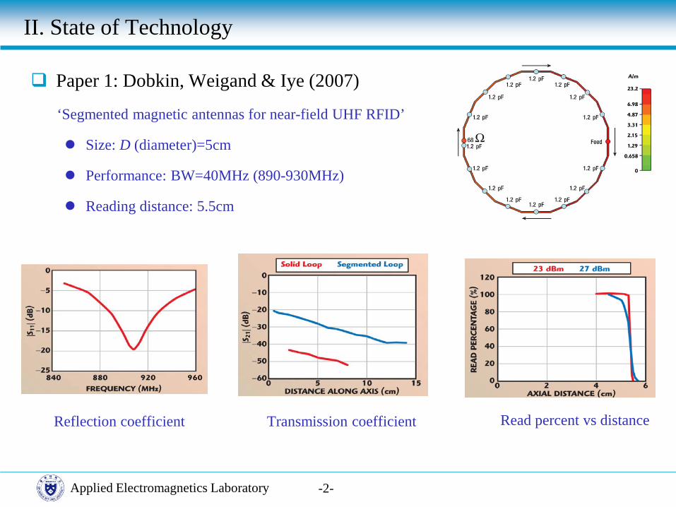
Paper 1: Dobkin, Weigand & Iye (2007)
‘Segmented magnetic antennas for near-field UHF RFID’
Size: D (diameter)=5cm
Performance: BW=40MHz (890-930MHz)
Reading distance: 5.5cm
-2-
Reflection coefficient Transmission coefficient Read percent vs distance
Applied Electromagnetics Laboratory
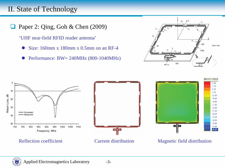
Paper 2: Qing, Goh & Chen (2009)
‘UHF near-field RFID reader antenna’
Size: 160mm x 180mm x 0.5mm on an RF-4
Performance: BW= 240MHz (800-1040MHz)
-3-
Reflection coefficient Current distribution Magnetic field distribution
II. State of Technology

Applied Electromagnetics Laboratory
Paper 3: Qing, Goh & Chen (2010)
‘A broadband UHF near-field RFID antenna’
Size: 175mm x 180mm x 0.5mm on an RF-4
Performance: BW= 230MHz (820-1050MHz)
Read distance (-30dB): 24mm
-4-
Reflection coefficient Current distribution Magnetic field distribution
II. State of Technology

Applied Electromagnetics Laboratory
II. State of Technology
Paper 4: Ong, Qing, Goh & Chen (2010)
‘A segmented loop antenna for UHF near-field RFID’
Size: 170mm x 180mm x 0.5mm on an RF-4
Performance: BW= 300MHz (770-1070MHz)
Reading distance (-30dB): 24mm
-5-
Hz along y -axis
Magnetic field distribution H
z along x -axis

Applied Electromagnetics Laboratory
II. State of Technology
Paper 5: Lee, Cho, Ryoo, Park & Choo (2009)
‘Planar near-field RFID reader antenna using opposite-directed currents’
Size (inner): 120mm x 177mm x 30.6mm
Performance: Reading distance: 24cm
Reading area: 744cm2
-6-
Magnetic field distribution
Applied Electromagnetics Laboratory
II. State of Technology
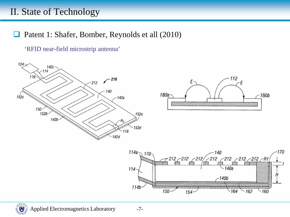
Patent 1: Shafer, Bomber, Reynolds et all (2010)
‘RFID near-field microstrip antenna’
-7-

Applied Electromagnetics Laboratory
II. State of Technology
Patent 2: Choi, Kim, Bae, Choi and Chae (2010)
‘Near-field radio frequency identification reader antenna’
-8-
Applied Electromagnetics Laboratory
II. State of Technology
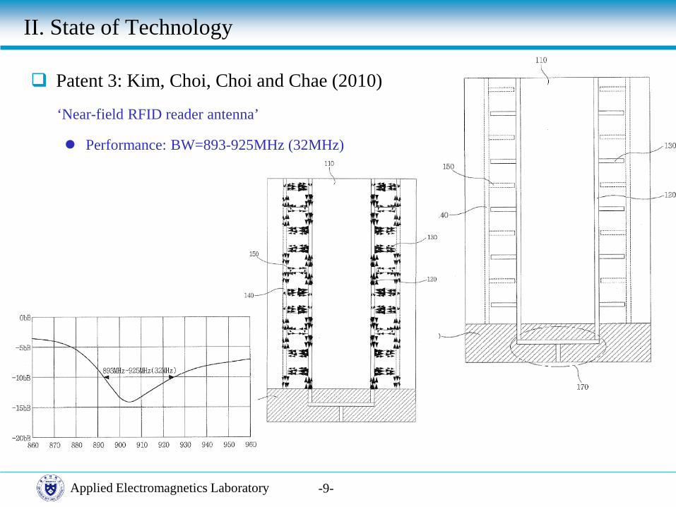
Patent 3: Kim, Choi, Choi and Chae (2010)
‘Near-field RFID reader antenna’
Performance: BW=893-925MHz (32MHz)
-9-

Applied Electromagnetics Laboratory
II. State of Technology
Product 1: Impinj Inc. (CS-777-2)
‘Near-Field Reader Antenna’
Size: Diameter= 30cm, Height=6cm, Weight= 0.9kg
Performance: BW=902-928MHz (26MHz)
Far Field Gain = 6dBi
Read Range = 40 cm
-10-
Product 2: GAO RFID Inc.
‘Standalone RFID Reader’
Size: 114.3mm x 114.3mm x 50.8mm, Weight= 220g
Performance: BW=860-960MHz (100MHz)
Read Range = 10 cm
Housing = ABS
Applied Electromagnetics Laboratory
II. State of Technology
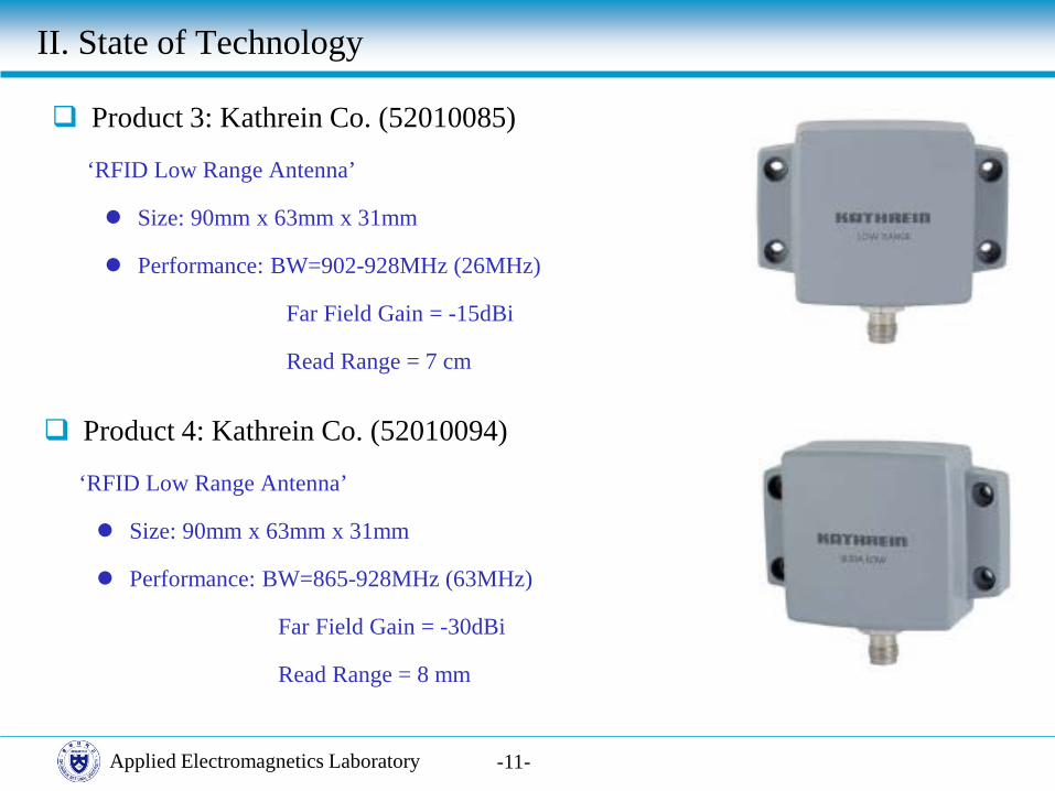
Product 3: Kathrein Co. (52010085)
‘RFID Low Range Antenna’
Size: 90mm x 63mm x 31mm
Performance: BW=902-928MHz (26MHz)
Far Field Gain = -15dBi
Read Range = 7 cm
-11-
Product 4: Kathrein Co. (52010094)
‘RFID Low Range Antenna’
Size: 90mm x 63mm x 31mm
Performance: BW=865-928MHz (63MHz)
Far Field Gain = -30dBi
Read Range = 8 mm

Applied Electromagnetics Laboratory
III. Reference Tag Antenna
-12-
3D View
Size: 49mm x 60mm x 0.05mm
S11: 892.7-942MHz (49MHz)
Substrate: PET εr=3.9, tanδ=0.003, t=50µm
x
y
z
Feed position: g=2.27mm

Applied Electromagnetics Laboratory
III. Reference Tag Antenna
-13-
Performance
3D Gain:
G abs: 0.9dB G theta: 0.49dB G phi: 0.9dB
Near magnetic field: at 2cm above the antenna surface
2D-|H| 1D-Hx 1D-Hy 1D-Hz
Applied Electromagnetics Laboratory
IV. Reference Far-Field Antenna
-14-
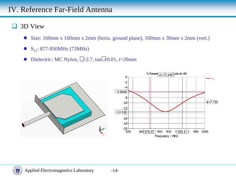
3D View
Size: 160mm x 160mm x 2mm (horiz. ground plane), 160mm x 30mm x 2mm (vert.)
S11: 877-950MHz (73MHz)
Dielectric: MC Nylon, δr=2.7, tanδ=0.01, t=20mm

Applied Electromagnetics Laboratory
IV. Reference Far-Field Antenna
-15-
Performance
3D Gain:
G abs: 6.55dB G theta: 3.84dB G phi: 3.95dB
Near magnetic field: at 2cm above the antenna surface
2D-|H| 1D-Hx 1D-Hy 1D-Hz

Applied Electromagnetics Laboratory -16
Tag Read Performance
Tag position: above the aperture center
S11reader
S11tag
S21transmission
Tag position
IV. Reference Far-Field Antenna

Applied Electromagnetics Laboratory
V. Design of Antenna Type 1A
-17-
Type 1A: Cavity GP+ABS Cover
Antenna Geometry: FR-4 (δr=4.4, tanδ=0.02), 130.2mm x 40mm x 1mm

Applied Electromagnetics Laboratory
V. Design of Antenna Type 1A
-18-
Antenna Housing
Metal case: 140mm x 50mm x 15mm, t=2mm
ABS cover: (δr=2.8, tanδ=0.01) 140mm x 50mm x 2mm
Antenna-to-ground spacing: 3.5mm
Antenna Performance
S11: 909-928MHz (18MHz)

Applied Electromagnetics Laboratory -19-
Antenna Performance
Far-Field 3D Gain:
G abs: -25.65dB G theta: -35.6dB G phi: -25.8dB
Near magnetic field: at 2cm above the antenna surface
2D-|H| 1D-Hx 1D-Hy 1D-Hz
V. Design of Antenna Type 1A

Applied Electromagnetics Laboratory
V. Design of Antenna Type 1A
-20
Tag Read Performance
Tag position: above the aperture center
S11reader
S11tag
S21transmission
Tag position

Applied Electromagnetics Laboratory
V. Design of Antenna Type 1A
-21-
S11reader
S11tag
S21transmission
Tag position
Tag Read Performance
Tag position: above the aperture center

Applied Electromagnetics Laboratory
V. Design of Antenna Type 1A
-22-
S11reader
S11tag
S21transmission
Tag position
Tag Read Performance
Tag position: above the aperture center

Applied Electromagnetics Laboratory
V. Design of Antenna Type 1A
-23-
S11reader
S11tag
S21transmission
Tag position
Tag Read Performance
Tag position: above the aperture center

Applied Electromagnetics Laboratory
V. Design of Antenna Type 1A
-24-
Tag position
x
y
Tag Read Uniformity
Tag position: at z=2cm above the aperture
-50 -40 -30 -20 -10 0 10 20 30 40 50-50-45-40-35-30-25-20-15-10-50
Tran
smiss
ion
coef
ficien
t in
dB
y-axis
-100 -80 -60 -40 -20 0 20 40 60 80 100-50-45-40-35-30-25-20-15-10-50
Tran
smiss
ion
coef
ficien
t in
dB
x-axis
x -variation
y -variation
Applied Electromagnetics Laboratory
VI. Design of Antenna Type 1B
-25-
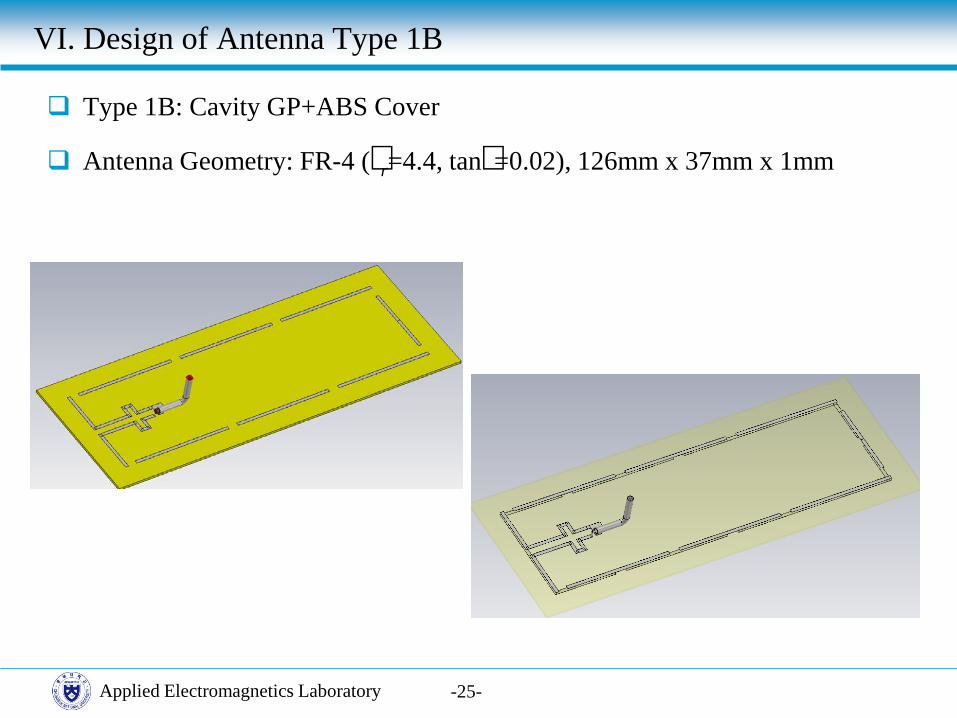
Type 1B: Cavity GP+ABS Cover
Antenna Geometry: FR-4 (δr=4.4, tanδ=0.02), 126mm x 37mm x 1mm

Applied Electromagnetics Laboratory
VI. Design of Antenna Type 1B
-26-
Antenna Housing
Metal backing: 140mm x 50mm (no sidewall), t=2mm
ABS cover: (δr=2.8, tanδ=0.01) 140mm x 50mm x 2mm
Antenna-to-ground spacing: 3.5mm
Antenna Performance
S11: 903-922MHz (19MHz)
Applied Electromagnetics Laboratory -27-
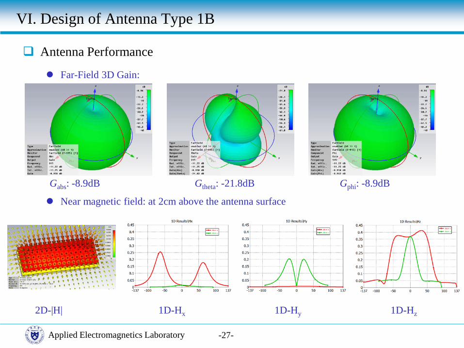
Antenna Performance
Far-Field 3D Gain:
G abs: -8.9dB G theta: -21.8dB G phi: -8.9dB
Near magnetic field: at 2cm above the antenna surface
2D-|H| 1D-Hx 1D-Hy 1D-Hz
VI. Design of Antenna Type 1B

Applied Electromagnetics Laboratory
VI. Design of Antenna Type 1B
-28-
S11reader
S11tag
S21transmission
Tag position
Tag Read Performance
Tag position: above the aperture center

Applied Electromagnetics Laboratory
VI. Design of Antenna Type 1B
-29-
S11reader
S11tag
S21transmission
Tag position
Tag Read Performance
Tag position: above the aperture center

Applied Electromagnetics Laboratory
VI. Design of Antenna Type 1B
-30-
S11reader
S11tag
S21transmission
Tag position
Tag Read Performance
Tag position: above the aperture center
Applied Electromagnetics Laboratory
VI. Design of Antenna Type 1B
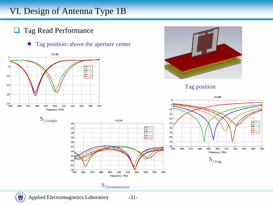
-31-
S11reader
S11tag
S21transmission
Tag position
Tag Read Performance
Tag position: above the aperture center

Applied Electromagnetics Laboratory
VI. Design of Antenna Type 1B
-32-
x -variation
Tag position
x
y
Tag Distance Uniformity
Tag position: at z=2cm above the aperture
y -variation
-100 -80 -60 -40 -20 0 20 40 60 80 100-50-45-40-35-30-25-20-15-10-50
Tran
smiss
ion
coef
ficien
t in
dB
x-axis
-50 -40 -30 -20 -10 0 10 20 30 40 50-50-45-40-35-30-25-20-15-10-50
y-axis

Applied Electromagnetics Laboratory
VII. Design of Antenna Type 1C
-33-
Type 1C: Cavity GP +Rohacell Cover
Antenna Geometry: FR-4 (δr=4.4, tanδ=0.02), 113mm x 37mm x 1mm

Applied Electromagnetics Laboratory
VII. Design of Antenna Type 1C
-34-
Antenna Housing
Metal backing: 140mm x 50mm (no sidewall), t=2mm
Rohacell (31 IG/A) fill: δr=1.05, tanδ=0.0003,
140mm x 50mm x 15mm
Antenna-to-ground spacing: 4mm (with Rohacell fill)
Antenna Performance
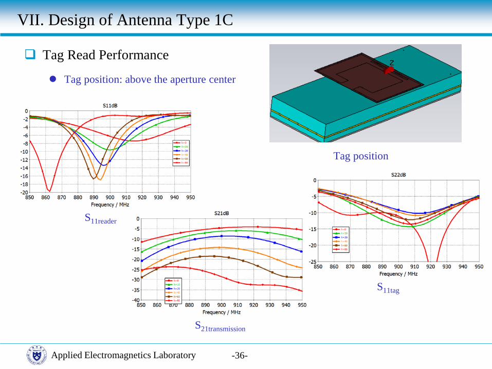
S11: 905-922MHz (17MHz)

Applied Electromagnetics Laboratory -35-
Antenna Performance
Far-Field 3D Gain:
G abs: -9.14dB G theta: -19.6dB G phi: -9.14dB
Near magnetic field: at 2cm above the antenna surface
2D-|H| 1D-Hx 1D-Hy 1D-Hz
VII. Design of Antenna Type 1C
Applied Electromagnetics Laboratory
VII. Design of Antenna Type 1C
-36-
S11reader
S11tag
S21transmission
Tag position
Tag Read Performance
Tag position: above the aperture center

Applied Electromagnetics Laboratory
VII. Design of Antenna Type 1C
-37-
S11reader
S11tag
S21transmission
Tag position
Tag Read Performance
Tag position: above the aperture center

Applied Electromagnetics Laboratory
VII. Design of Antenna Type 1C
-38-
S11reader
S11tag
S21transmission
Tag position
Tag Read Performance
Tag position: above the aperture center

Applied Electromagnetics Laboratory
VII. Design of Antenna Type 1C
-39-
S11reader
S11tag
S21transmission
Tag position
Tag Read Performance
Tag position: above the aperture center

Applied Electromagnetics Laboratory
VII. Design of Antenna Type 1C
-40-
Tag position
x
y
Tag Distance Uniformity
Tag position: at z=2cm above the aperture
x -variation
y -variation
-100 -80 -60 -40 -20 0 20 40 60 80 100-50-45-40-35-30-25-20-15-10-50
Tran
smiss
ion
coef
ficien
t in
dB
x-axis
-50 -40 -30 -20 -10 0 10 20 30 40 50-50-45-40-35-30-25-20-15-10-50
Tran
smiss
ion
coef
ficien
t in
dB
y-axis

Applied Electromagnetics Laboratory
VIII. Appendix
-41-
Mesh problem
Tag position: at z=5cm above the aperture
S11reader vs mesh
S11tag vs mesh
S21transmission vs mesh

Applied Electromagnetics Laboratory
VIII. Appendix
-42-
Tuning problem
Antenna type 1B with high mesh
S11 vs cut
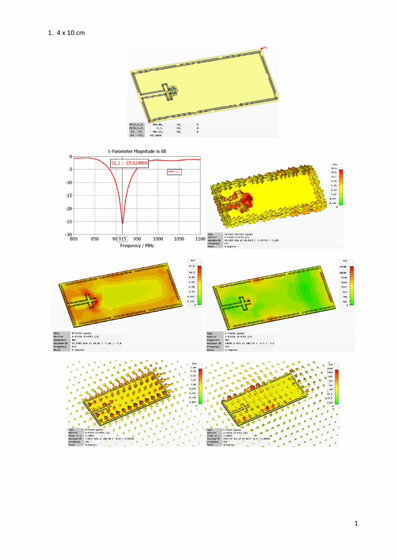
1. 4 x 10 cm
1

Array
2

2. 20 x 20 cm (segmented loop antennas)
a.
3

b.
4

5

c.
6

d.
7
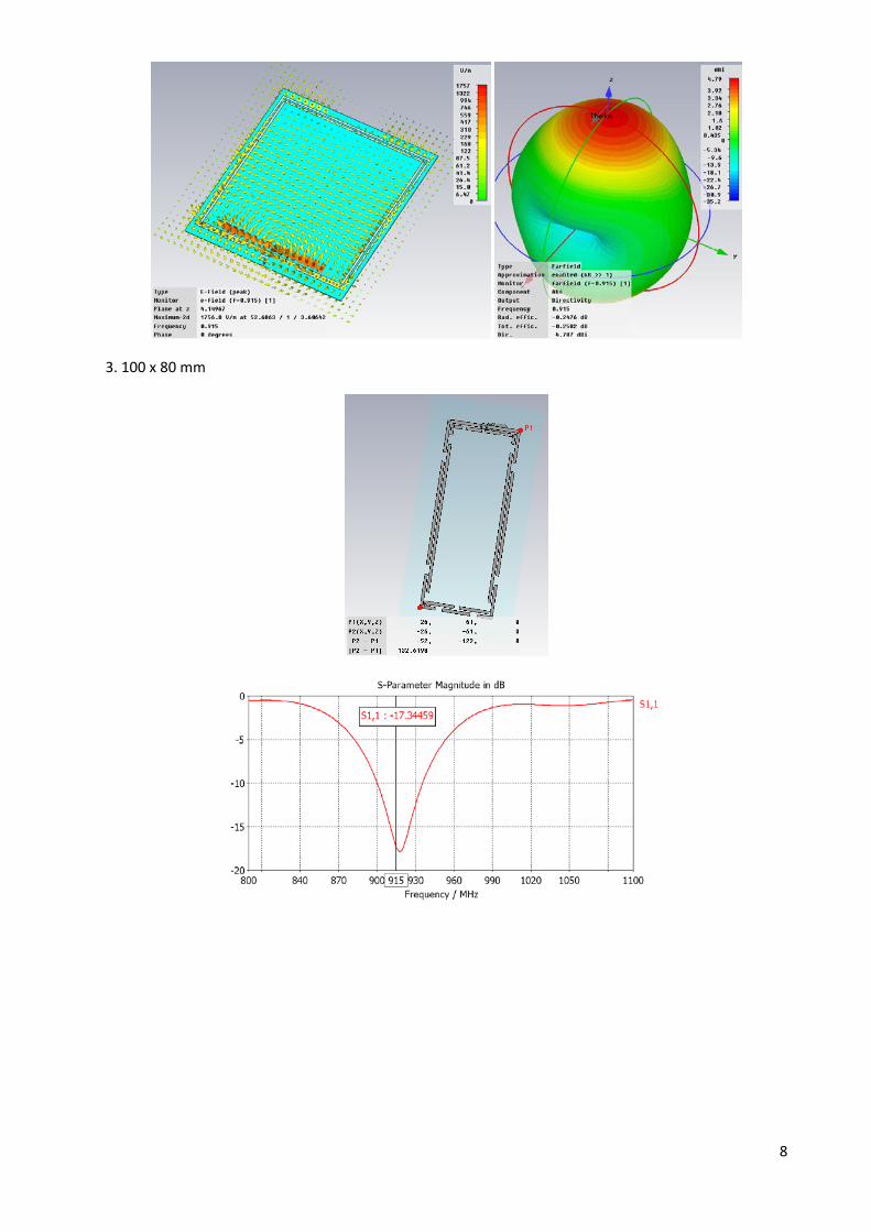
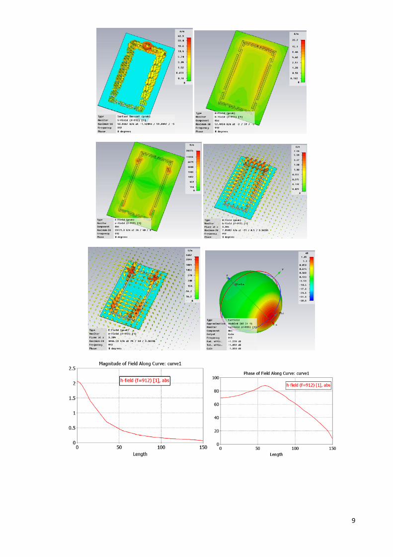
3. 100 x 80 mm
8
9


![IEEE TRANSACTIONS ON ANTENNAS AND PROPAGATION, …ael.cbnu.ac.kr/ael/research/ael_research/NGFA/Type3a/lu-square slot,cp.pdffed by a Wilkinson power divider [6] and the annular-ring](https://img.pdfslide.net/doc/110x75/5f28afcc92d255705527d51b/ieee-transactions-on-antennas-and-propagation-aelcbnuackraelresearchaelresearchngfatype3alu-square.jpg)