Embed Size (px)
Citation preview

JORNADA TÉCNICA EN HONOR A RAVINDRA GETTU. 5 DE OCTUBRE DE 2004
1
Near surface mounted CFRP-based technique for the strengthening of concrete structures
Joaquim Barros, José Sena-Cruz, Salvador Dias, Débora Ferreira, Adriano Fortes
University of Minho Department of Civil Engineering
Campus de Azurém, 4800-058 Guimarães Portugal
Abstract: To assess the effectiveness of the Near Surface Mounted (NSM) strengthening technique, an experimental program was carried out involving reinforced concrete (RC) columns and beams. In columns failing in bending the present work shows that the failure strain of the Carbon Fiber Reinforced Polymer (CFRP) laminates can be attained using the NSM technique. Beams failing in bending were also strengthened with CFRP laminates in order to double their load carrying capacity. This goal was attained and maximum strain levels of about 90% of the CFRP failure strain were recorded. Performance of externally bonded reinforcing (EBR) and NMS techniques was compared for strengthening RC beams failing in shear. NMS was much more effective, not only in terms of the increase of the load carrying capacity and deformability at beam failure, but also with respect to the time consuming nature of the corresponding strengthening procedures. To assess the bond behavior of CFRP to concrete, pullout-bending tests were carried out. The influences of bond length and concrete strength on the bond behavior were analyzed. Keywords: Carbon Fiber Reinforced Polymers, Strengthening, Concrete, Columns, Beams, Flexural, Shear, Bond
1. Introduction
The use of fiber reinforced polymer (FRP) materials for structural repair and strengthening has continuously increased during previous years, due to several advantages associated with these composites when compared to conventional materials like steel. These benefits include low weight, easy installation, high durability and tensile strength, electromagnetic neutrality and practically unlimited availability in size, geometry and dimension [1, 2].
FRP laminates and sheets are generally applied on the faces of the elements to be strengthened, using externally bonded reinforcing (EBR) technique. The research carried out up to now has revealed that this technique cannot mobilize the full tensile strength of FRP materials due to premature debonding [3, 4]. Since FRP systems are directly exposed to weathering conditions, negative influences of freeze/thaw cycles [5] and the effect of high and low temperatures [6] should be taken into account in the reinforcing performance of these materials. In
addition, EBR systems are susceptible to fire and acts of vandalism.
In an attempt at overcoming these drawbacks, a recent strengthening technique designated by near surface mounted (NSM) has been proposed, where FRP rods are fixed into pre-cut grooves on the concrete cover of the elements to be strengthened [7]. This technique has been used in some practical applications [8, 9, 10] and several benefits have been pointed out.
Blaschko and Zilch [11] proposed a similar strengthening technique based on introducing laminate strips of CFRP into pre-cut slits on the concrete cover. The CFRP was bonded to concrete by epoxy adhesive. Despite the few number of carried out tests, the obtained results revealed this to be a promising technique.
In recent years, carbon and glass FRP sheets have been applied using the retrofitting technique to increase concrete confinement [12, 13] and bending resistance [14] of reinforced concrete (RC) columns. This increase is dependent on the thickness (number of layers) and on the material properties of the FRP system [13, 15], as well as on column cross-sectional geometry [16]. Blaschko and Zilch [11] showed that the bending resistance of concrete elements can be significantly increased using laminate strips bonded to concrete into slits. The effectiveness of this strengthening technique, however, has not yet been appraised in concrete columns failing in bending and simultaneously submitted a kind of seismic loading configuration (lateral cyclic loading and static axial compression load). One of the goals of the present work is to assess the benefits of this strengthening technique on this type of structural elements.
EBR techniques using CFRP materials have also been used to increase the shear resistance of RC beams [17, 18, 19]. Premature failures of these CFRP systems, however, inhibited the attainment of the desired strengthening efficacy level. In an attempt at obtaining a more effective shear strengthening technique for concrete beams, De Lorenzis et al. [20] used CFRP rods introduced into grooves made onto the vertical faces of concrete beams. This strengthening technique provided a significant increase on the shear resistance of the strengthened beams. Following similar strengthening technique

JORNADA TÉCNICA EN HONOR A RAVINDRA GETTU. 5 DE OCTUBRE DE 2004
2
procedures, but using laminate strips of CFRP bonded to concrete into thin slits, the effectiveness of this technique for shear strengthening is also assessed in the present work.
Since bond behavior analysis is a requirement for understanding the stress transfer process between concrete and CFRP, the present work conducts a pullout-bending test similar to the one proposed by RILEM for assessing the bond characteristics of conventional steel rods [21]. Using the same slit size and epoxy adhesive, bond behavior was analyzed in order to determine the influences of both bond length and concrete strength.
2. Experimental program and strengthening tecnhique
Table I summarizes the experimental program and
its main objectives. It includes a group of series of tests with RC columns and RC beams, all failing in bending, a group of series of tests with RC beams failing in shear, and a group of series of pullout-bending tests. The first two groups have the main purpose of assessing the effectiveness of the NSM technique on elements failing in bending and on elements failing in shear, respectively. The percentage of the steel reinforcement ratio, slρ (ratio between the cross sectional area of longitudinal steel bars and the cross sectional area of the concrete element), has a recognized influence on the effectiveness of FRP strengthening techniques. To assess this influence on the NSM technique applied to RC elements failing in bending, tests with columns and beams of distinct slρ were carried out. The effectiveness of EBS and NSM techniques were compared in the series of RC beams failing in shear.
Elements failing in bending Elements failing in shear
RC columns RC beams Cyclic tests Monotonic tests
Cyclic horizontal increasing load and
static axial load Four point bending tests
Assess the influence of the longitudinal steel
reinforcement ratio, slρ
Compare the performance of EBR and NSM
techniques
Two distinct slρ
Four distinct slρ
Strips of wet lay-up CFRP; CFRP laminates embedded
into slits Pullout-bending tests
Concrete beams Monotonic tests
Four point bending tests Asses the bond behavior of CFRP concrete
Bond Length and concrete strength
Table I : Experimental program
200
5050
5050
CFRPlaminate strips
Loadingplan
Concrete cover
CFRP(≅1.5×10)
20
200
2020
20
Slit
Epoxyadhesive
≅ 15
≅ 5
Units: mm
(a) - Reinforced concrete columns failing in bending ConcretecoverSteelbarsConcrete
core
Stirrups
Slit
Epoxyadhesive
CFRPlaminateCFRP
laminate strips
≅ 5
≅ 15
Units: mm
10017
0-18
0
(b) - Reinforced concrete beams failing in bending
Longitudinalsteel bars
A
A
CFRP laminates bondedinto slits by epoxy adhesive
150
150
Epoxyadhesive
CFRPlaminate Units: mm
≅ 10 (widthof CFRP)
Tensile longitudinalsteel bars
CFRP laminatesbonded into slitsby epoxy adhesive
Compressivelongitudinal steel bars
Section AA
≅ 15 (slit)50 900 50
(c) - Reinforced concrete beams failing in shear
Fig. 1 : NSM CFRP Technique
The strengthening technique is made up of the
following steps (see Figure 1): - Using a diamond cutter, slits of 4 to 5 mm width
and 12 to 15 mm depth are executed on the concrete surface of the elements to be strengthened;
- Slits are cleaned by compressed air; - Laminate strips of CFRP are cleaned by acetone; - Epoxy adhesive is produced according to
supplier recommendations; - Slits are filled with the epoxy adhesive; - The epoxy adhesive is applied on the faces of
the laminate strips of CFRP; - Laminate strips of CFRP are introduced into the
slits and the epoxy adhesive in excess is removed.

JORNADA TÉCNICA EN HONOR A RAVINDRA GETTU. 5 DE OCTUBRE DE 2004
3
The curing/hardening process of the epoxy adhesive lasted for, at least, five days prior to testing the strengthened elements.
3. Materials properties
3.1. Concrete and steel bars Table II includes the main properties of the
concrete and steel bars used in the experimental program. The concrete compression strength, fcm, was obtained from uniaxial compression tests with cylinder specimens of 150 mm diameter and 300 mm height. The concrete tensile flexural strength, fctm,fl, and the concrete fracture energy, Gf, were obtained from three point bending tests with notched beams, performed according to the recommendations of RILEM [22]. Each value was the average result of, at least, three tests. In the series of RC columns, low strength concrete and steel bars of moderate strength and smooth surface were used to obtain representative specimens of concrete columns of Portuguese buildings built before the 1980s.
Steel bars were tested according to the standard EN 10 002-1 [23], and each result was the average of at least five tests.
3.2. CFRP and epoxy adhesive
According to the supplier, the MBrace Sheet
C5-30 used as shear reinforcement in beams failing in shear, has the properties indicated in Table III. Laminate strips of CFRP used in the NSM technique, with the designation of CFK 150/2000 10x1.4, were delivered in rolls and had cross sectional dimensions of 9.59±0.09 mm width and 1.45±0.005 mm thickness (average values of fifteen measures). From three uniaxial tensile tests carried out according to ISO 527-5 standard [24], it was verified that the tensile behavior of the CFRP roll delivered for the concrete column series of tests was distinct from the tensile behavior registered in the rolls delivered for the beam series of tests, see Table III [25, 26]. This table also includes the Young’s modulus and the tensile strength range of the epoxy adhesive used in the NSM technique, obtained from five uniaxial tensile tests carried out according to ISO 527-3 standard [27].
3.3. Epoxy mortar
To anchor the laminate strips of CFRP to the column foundation in the RC column test series, an epoxy mortar was used (see Figure 2). This epoxy mortar was composed of one part epoxy and three parts of previously washed and dried fine sand (parts measured in weight). Following the European standard EN 196-1 [28], an average compressive
strength of 51.7 N/mm2 and an average flexural tensile strength of 35.4 N/mm2 was obtained at 28 days [29].
Concrete Steel Element
type fcm [MPa]
fctm,fl[MPa]
Gf [N/mm]
φs [mm]
fsy [MPa]
fsu [MPa]
6 352.4 532.810 323.3 456.5RC
columns16.7 (28)1
2.62 (28)
0.08 (28)
12 364.8 518.86 - 750
Elem
ents
faili
ng
in b
endi
ng
RC beams
46.1 (90) - - 8 - 500
(stirrups) 6 540 694
(long.) 6 618 691
Elem
ents
fa
iling
in sh
ear
RC beams
49.5 (28)
56.2 (105)
- -
10 464 581
Pullo
ut
bend
ing
test
s Concrete
beams 34.9 5.9 - - - -
1 - The values in brackets represent the age, in days, when the tests were carried out.
Table II : Properties of the concrete and steel bars
CFRP system Main properties
Type MaterialTensile strength(MPa)
Young's modulus
(GPa)
Ultimatestrain (%)
Thickness(mm)
Primer 12 0.7 3.0 - Epoxy 54 3 2.5 - MBrace
Sheet C5-301
Sheet 3000 390 0.8 0.167 Adhesive 16-22 5 - -
(i) 1741 153 1.1 (ii) 2740 158 1.7
CFK 150/2000 10×1.42 Laminate
(iii) 2286 166 1.3 9.6
1 According to the supplier; 2 Evaluated from experimental tests (i) Colums; (ii) Beams failing in bending and pullout-bending tests; (iii) Beams failing in shear
Table III : Properties of the CFRP materials
CFRP laminate strips areintroduced into slits previouslyfilled with epoxy adhesive
Holes of 100 mm depth,filled by epoxy mortar
The concrete cover isreplaced by epoxy mortar10
0-15
0
800400
300
1000
Section A-A'
Load direction
Footing
Col
umn
≅ 30
Units: mm
Fig. 2 : Strengthening technique in specimens of RC column (Section A-A' in Figure 1a)

JORNADA TÉCNICA EN HONOR A RAVINDRA GETTU. 5 DE OCTUBRE DE 2004
4
4. Concrete columns failing in bending 4.1. Series of tests
Columns of reinforced concrete framed structures
are the most vulnerable elements since their failure leads to the collapse of the structure. To assess the effectiveness of the NSM strengthening technique for concrete columns submitted to static axial compression load and cyclic horizontal increasing load, the three series of reinforced concrete columns, indicated in Table IV, were tested. Series NON consisted of non-strengthened columns, series PRE was composed of concrete columns strengthened with CFRP laminate strips before testing, and series POS consisted of previously tested columns of series NON which were post-strengthened with CFRP. The designation Pnm_s was attributed to tests of series s (NON, PRE or POS), where n represents the diameter of the longitudinal steel bars, in mm, (10 or 12), and m can be a or b, since there are two specimens for each series of distinct longitudinal steel reinforcement ratio.
Series Longitudinal steel
reinforcement NON1 PRE2 POS3 P10a_NON P10a_PRE P10a_POS 4φ10
(Asl = 314 mm2) P10b_ NON P10b_PRE P10b_POS P12a_ NON P12a_PRE P12a_POS 4φ12
(Asl = 452 mm2) P12b_ NON P12b_PRE P12b_POS 1 Non-strengthened; 2 Strengthened before testing; 3 Columns of NON series after have been tested and strengthened.
Table IV : Denominations for the RC column specimens
4.2. Test set-up and procedure
The test set-up is illustrated in Figure 3, where it
can be seen that each specimen is composed of a column monolithically connected to a footing fixed to a foundation block by four steel bars. A constant vertical load of approximately 150 kN was applied to the column, inducing an axial compression stress of 3.75 N/mm2. Linear variable displacement transducers (LVDTs) were used to record the horizontal displacements of the column as well as any vertical movement of the footing, see Figure 4. The position of the strain-gauges (SG) glued on the CFRP is also indicated in this figure. The tests were carried out with closed loop servo-controlled equipment. A history of displacements was imposed for LVDT1, located at the same height as the horizontal actuator, see Figures 3 and 4. The history of horizontal displacements included eight load cycles between ±2.5 mm and ±20.0 mm, in increments of ±2.5 mm, with a displacement rate of 150 µm/s [29].
4.3. Specific strengthening procedures
Figure 2 illustrates the strengthening technique adopted for the concrete columns. To anchor the CFRP laminate strips to the footing and to maintain their vertical position, the concrete cover of a region having a height of 100 to 150 mm from the bottom of the column (denoted here by “non-linear hinge region”) was removed. Afterwards, slits were executed along the faces subjected to tensile stress. In the alignment of the slits, perforations of about 100 mm depth were made in the footing to anchor the CFRP laminate strips. The slits and the holes were cleaned using steel brushes and compressed air. After filling the grooves with the epoxy adhesive, laminate strips of CFRP were inserted into the slits and the “non-linear hinge region” and the holes in the footing were filled with epoxy mortar. A more detailed description of the strengthening technique is provided elsewhere [29].
200
200
1000
200
1000
300
600
1200200 200 200 200
Footing
Foundation block
Col
umn
(200
x200
)
Compression/tensionactuator
Compression actuator
Loadcell C2
Loadcell C1
1000
LVDT1
Units: mm
Fig. 3 : Test set-up (dimensions in mm)
Footing(Side B)
812
1616
14
2Footing(Side A)
1212
Footing(Side C)
SG 1
SG 2
SG 3
SG 4
SG 5
Side D
Side B
Side
C
Side
A
= = = = 5
Horizontalactuator
555
2
SG 6
LVD
T6±
Units: mm
( 1
2.5m
m)
LVD
T7±( 1
2.5m
m)
LVDT5±( 12.5mm)
LVDT4( 12.5mm)±
( 25mm)±LVDT3
( 25mm)LVDT2±
( 25mm)LVDT1±
Fig. 4 : Location of the displacement transducers (LVDT) and strain gauges (SG) in test set-up

JORNADA TÉCNICA EN HONOR A RAVINDRA GETTU. 5 DE OCTUBRE DE 2004
5
4.4. Results Representative results are presented in this
section. Detailed results and analysis can be found elsewhere [30].
4.4.1 Load carrying capacity
The maximum compressive and tensile forces
obtained in the tests are given in Tables V and VI.
Series PRE Force P10a_PRE
(111) P10b_PRE
(113) P12a_PRE
(110) P12b_PRE
(115) Tensile
[kN] 37.14 40.63 44.13 39.81
Compressive[kN] -38.54 -37.96 -43.66 -36.64
Note: Values inside parenthesis indicate the age of the columns at testing, in days.
Table V : Maximum forces obtained in the columns of
series PRE
Force Series P10a_ P10b_ P12a_ P12b_
NON [kN] 16.67 (86)
21.78 (85)
26.35 (85)
29.31 (85)
POS [kN] 37.96 (146)
41.38 (130)
34.11 (150)
45.54 (154)
Tensile
Increase [%] 127.70 89.99 29.45 55.37
NON [kN] -19.76 (86)
-24.07 (85)
-30.52 (85)
-32.27 (85)
POS [kN] -34.11 (146)
-43.1 (130)
-37.03 (150)
-41.58 (154)
Compressive
Increase [%] 72.62 79.06 21.33 28.85Note: Values inside parenthesis indicate the age of the columns at testing, in days.
Table VI : Maximum forces obtained in the columns of
NON and POS series
The differences recorded in the maximum forces of the columns from the same series were due to the compression strength variability of the concrete of these columns (two batches were required to build a specimen), as well as differences in the positioning of the steel bars and their properties. Taking into account the results obtained from the non-strengthened columns (series NON), a significant increase in the maximum load of the columns of series PRE (strengthened before testing) and POS (strengthened after NON series had been tested) was observed. The comparison between series NON and PRE should be made with caution, because the concrete compression strength of the columns of these two series was not the same. As the CFRP reinforcement ratio was the same for all the column specimens tested, the increase of the ultimate load was larger in columns of a lower steel reinforcement ratio. The increase of the load carrying capacity in PRE and POS series was similar.
4.4.2 Force-deflection relationship
Figure 5 depicts a typical relationship between the horizontal force and the deflection at LVDT1 (see Figure 3). Since this strengthening technique does not provide significant concrete confinement, the increase on the dissipated energy was marginal.
-50
-40
-30
-20
-10
0
10
20
30
40
50
-25 -20 -15 -10 -5 0 5 10 15 20 25
Displacement (mm)
Forc
e (k
N)
P10a_NON
P10a_PRE
Fig. 5 : Cyclic force-deflection (at LVDT1) relationship for column P10a
The increment on the load carrying capacity,
however, was significant as can be seen in Figure 6, where a typical envelope of the maximum values of the relationship between the maximum force registered in the load cycles and its corresponding deflection in the LVDT1 is represented.
-50
-40
-30
-20
-10
0
10
20
30
40
50
-25 -20 -15 -10 -5 0 5 10 15 20 25
Displacement (mm)
Forc
e (k
N)
P10b_NON
P10b_POS
Fig. 6 : Force-deflection (at LVDT1) envelop of all load cycles for column P10b

JORNADA TÉCNICA EN HONOR A RAVINDRA GETTU. 5 DE OCTUBRE DE 2004
6
4.4.3 Force-Strain relationship In the majority of the strengthened columns some
laminate strips of CFRP reached tensile strain values close to the ultimate rupture strain of the CFRP (≅1.0 %). Some CFRP laminate strips even failed at the main fracture surface of the concrete column. As an example, Figure 7 illustrates the relationship between the horizontal force applied to the column and the strain in the strain-gauge SG6, for the column P10a_POS. In strain-gauges located at the concrete failure region, similar relationships to that depicted in Figure 7 were obtained in the remaining columns.
10434
-50
-40
-30
-20
-10
0
10
20
30
40
50
-12000 -9000 -6000 -3000 0 3000 6000 9000 12000
Strain (µm/m)
Forc
e (k
N)
TensionCompression
Fig. 7 : Relationship between the force and the strain on the strain gauge SG6 (see Figure 4) for the column P10a_POS
5. Concrete beams failing in bending 5.1. Series of beams
Figure 8 represents the geometry of the beams, the
reinforcement arrangement and the number and position of the laminate strips of CFRP. The load configuration and the support conditions are also schematized. The cross sectional area of the CFRP, Af, applied in the beam of each series, was designed to achieve twice the ultimate load of the corresponding reference beam. Shear reinforcement was selected to assure bending failure prior to shear failure for all beams. The cross sectional area of the tensile longitudinal steel bars is also indicated in Figure 8, As. The longitudinal steel reinforcement was composed of bars of 6 mm and 8 mm diameters, while stirrups were made of bars of 6 mm diameter. The beams were tested at the age of about 90 days.
50 1400 (CFRP laminate) 50
7 stirrups Ø6 6 stirrups Ø3 7 stirrups Ø6
10 100 100
2Ø8
P/2 P/2
35 35 35
50
500 500 500
100 100 100 10035
80 80 80 100 100 100 100 100 100 10
50
1600
units: mm a)
180
2Ø8
V4R3V42Ø8
SERIES S1 SERIES S2
SERIES S3 SERIES S4
3Ø8
2Ø6
1002Ø6 1CFRP
laminate17
8
170
V12Ø8
V1R12Ø8
2Ø6
3Ø6
2 CFRPlaminates
3Ø6
2 CFRPlaminates
2Ø6
175
173
177
V22Ø8
V2R22Ø8
1Ø81Ø8 17
5
V3R2V32Ø8 2Ø8
3Ø8
3 CFRPlaminates
175
Af/As = 25.2 Af/As = 33.6
Af/As = 26.7 Af/As = 28.3units: mm
b)
CFRP
355012~ 1250
~
2512~
3530 25 25 25
epoxy adhesive
CFRP laminates
21
units: mm
≅ 1
≅ 10
≅ 1 ≅ 4
c)
Fig. 8 : Series of beams failing in bending: (a) load configuration and arrangement of longitudinal reinforcement, (b) cross section of series of beams, (c) strengthening details 5.2. Test configuration and measuring devices
To evaluate the strain evolution of the CFRP
laminate strips, strain gauges were glued on one of their lateral faces, according to the scheme shown in Figure 9. This figure also represents the position of

JORNADA TÉCNICA EN HONOR A RAVINDRA GETTU. 5 DE OCTUBRE DE 2004
7
the LVDTs used for measuring the deflections of the beams.
LVDT_2990 LVDT_2934
SG 3
LVDT_3558 LVDT_3468 LVDT_2987
SG 2SG 1
250 250
250 250 250 250 250 250
250
150(control)
units: mm
Fig. 9 : Measuring devices (LVDT - Linear Variable Displacement Transducer; SG – Strain Gauge)
5.3. Results
The failure modes and the interpretation of the
reinforcing mechanisms provided by laminate strips of CFRP have been presented elsewhere [30]. 5.3.1 Force-Deflection relationship
The force-deflection relationships for the series of
tested beams are depicted in Figure 10, and the main results are presented in TableVII. It is observed that the purpose of doubling the ultimate load ( maxF ) of the corresponding reference beam was practically achieved. The increase on the load at the onset of yielding the steel reinforcement ( syF - yielding load) was also significant, varying from 32% to 47%. The displacement corresponding to syF increased, as well
as the cracking load, crF , and the serviceability load,
servF , (the load for a deflection of L/400=3.75 mm, where L is the beam span). A maximum increase of 45% and 47% on servF and syF , respectively, was recorded.
Series Beam crF
[kN] servF
[kN] syF
[kN] maxF
[kN] max,fε
(%)
V1 8.5 18.6 24.5 28.2 S1
V1R1 10.7 22.7 32.31 50.3(1) 1.55
V2 8.1 21.7 37.5 41.0 S2
V2R2 12.3 31.4 52.28 78.5 1.28
V3 7.9 23.8 40.0 41.3 S3
V3R2 11.9 32.8 54.52 81.9 1.28
V4 8.1 32.3 46.9 48.5 S4
V4R3 14.1 40.4 69.11 94.9 1.06 (1) The test was canceled at a load of 50.3 kN, when the deflection at mid
span was greater than 25mm.
Table VII : Main results obtained in the series of beams
failing in bending
0
20
40
60
80
100
0 5 10 15 20 25 30
Displacement at mid-span (mm)
Load
(kN
)
CrackingSteel bars yieldingCFRP slidingV1R1V1
(a)
0
20
40
60
80
100
0 5 10 15 20 25 30
Displacement at mid-span (mm)
Load
(kN
)
CrackingSteel bars yieldingCFRP slidingV2R2V2
(b)
0
20
40
60
80
100
0 5 10 15 20 25 30
Displacement at mid-span (mm)
Load
(kN
)
CrackingSteel bars yieldingCFRP slidingV3R2V3
(c)
0
20
40
60
80
100
0 5 10 15 20 25 30
Displacement at mid-span (mm)
Load
(kN
)
CrackingSteel bars yieldingCFRP slidingV4R3V4
(d)
Fig. 10 : Force-deflection relationships of series: (a) S1, (b)
S2, (c) S3 and (d) S4 5.3.2 Force-Strain relationship
The relationships between the applied load and
the strains recorded in the strain gauges glued onto the laminate strips of CFRP (see Figure 9) are depicted in Figure 11. The maximum strains obtained from the strengthened beams, and presented in

JORNADA TÉCNICA EN HONOR A RAVINDRA GETTU. 5 DE OCTUBRE DE 2004
8
Table VII ( max,fε ), ranged from 62% to 91% of the
CFRP ultimate rupture strain ( fuε ≅ 1.7%), showing this strengthening technique has high level of effectiveness.
V1R1
0
4
8
12
16
0 20 40 60 80 100
Load (kN)
Stra
in (x
10-3
)
SG1SG3CrackingSteel bars yielding
SG1 SG2 SG3
(a)
V2R2
0
4
8
12
16
0 20 40 60 80 100
Load (kN)
Stra
in (x
10-3
)
SG1SG2SG3CrackingSteel bars yieldingCFRP sliding
SG1 SG2 SG3
(b)
V3R2
0
4
8
12
16
0 20 40 60 80 100
Load (kN)
Stra
in (x
10-3
)
SG1SG2SG3CrackingSteel bars yieldingCFRP sliding
SG1 SG2 SG3
(c)
V4R3
0
4
8
12
16
0 20 40 60 80 100
Load (kN)
Stra
in (x
10-3
)
SG1SG2SG3CrackingSteel bars yieldingCFRP sliding
SG1 SG2 SG3
(d)
Fig. 11 : Force-strain relationships of series: (a) V1R1, (b)
V2R2, (c) V3R2 and (d) V4R3
6. Concrete beams failing in shear 6.1. Series of tests
Three types of strengthening techniques using CFRP materials were applied to evaluate the most effective one for shear strengthening of RC beams. The series of beams tested (see Figure 12) contain a reference beam without any shear reinforcement (VB10); a beam with steel stirrups of 6 mm diameter spaced at 150 mm in the shear spans (VBE-15); a beam with strips of CFRP MBrace C5-30 sheet (properties in Table III) of two layers of 25 mm width and spaced at 80 mm in the shear spans (VBM-8); a beam with vertical laminate strips of CFRP bonded into pre-cut slits on the concrete cover of the vertical faces of the beam (see Figure 1c) and spaced at 100 mm (VBCV-10); and a beam with inclined (45 degrees) laminate strips of CFRP fixed onto the beam like the previous one (VBCI-15). The strips of the CFRP sheet in VBM-8 beam had a “U” shape (embracing the bottom and vertical faces of the beam). The amount of shear reinforcement applied in the beams was designed to provide similar shear resistance [1] and to assure that they would fail in shear mode. The beams were tested at the age of 105 days.
100
150
5Cross section
80300100100 100 100 100 150
150
VBE-15
300150 150
900
80 8060 80
5
80300 150
80300 6080 80
150
1504∅10
P P2∅6
P P
PP
P P
P P
VB10
VBM-8
VBCV-10 VBCI-15
Fig. 12 : Series of beams failing in shear (unities: mm)
6.2. Results
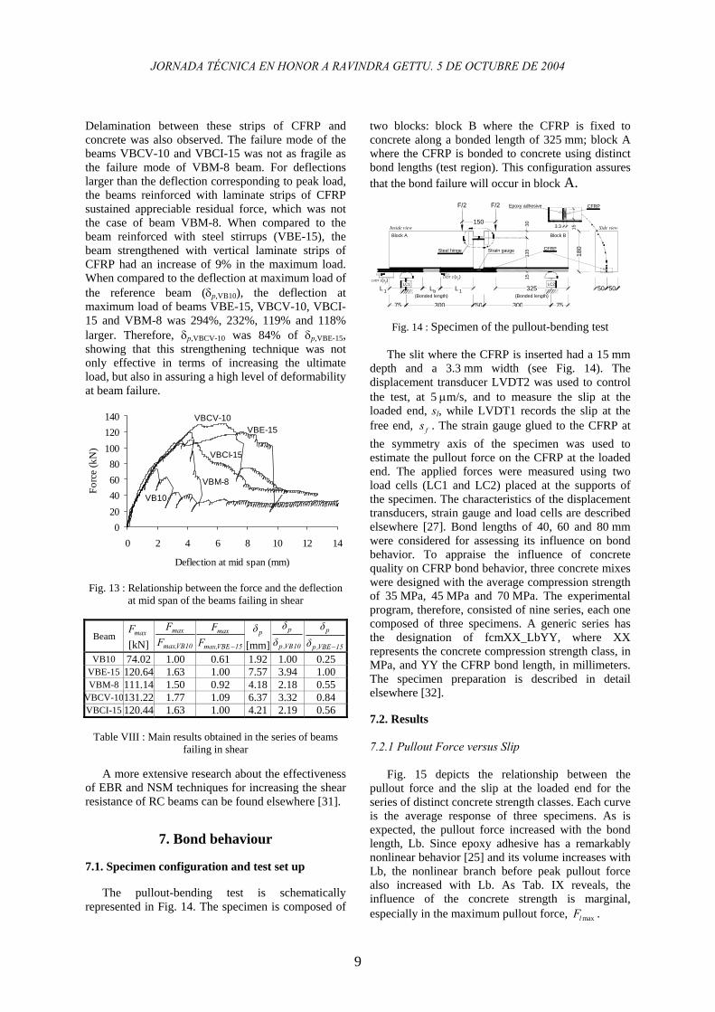
Figure 13 represents the relationship between the
load and the displacement at mid span of the tested beams. The main results are presented in Table VIII. When compared to the reference beam (VB10), the beams strengthened with CFRP materials attained an increase in the maximum load, Fmax, ranging from 50% to 77%. The highest and the lowest increase of Fmax occurred in the beam strengthened with vertical laminate strips of CFRP (VBCV-10) and in the beam strengthened with strips of CFRP sheet (VBM-8). The lowest effectiveness of the EBR technique (in the VBM-8 beam) can be justified by the failure modes of the strengthened beams. In VBM-8 beam a very fragile rupture occurred after the formation of the failure shear crack. The strips of CFRP sheet crossing the failure shear crack were ruptured at beam edges.
JORNADA TÉCNICA EN HONOR A RAVINDRA GETTU. 5 DE OCTUBRE DE 2004
9
Delamination between these strips of CFRP and concrete was also observed. The failure mode of the beams VBCV-10 and VBCI-15 was not as fragile as the failure mode of VBM-8 beam. For deflections larger than the deflection corresponding to peak load, the beams reinforced with laminate strips of CFRP sustained appreciable residual force, which was not the case of beam VBM-8. When compared to the beam reinforced with steel stirrups (VBE-15), the beam strengthened with vertical laminate strips of CFRP had an increase of 9% in the maximum load. When compared to the deflection at maximum load of the reference beam (δp,VB10), the deflection at maximum load of beams VBE-15, VBCV-10, VBCI-15 and VBM-8 was 294%, 232%, 119% and 118% larger. Therefore, δp,VBCV-10 was 84% of δp,VBE-15, showing that this strengthening technique was not only effective in terms of increasing the ultimate load, but also in assuring a high level of deformability at beam failure.
020406080
100120140
0 2 4 6 8 10 12 14
Deflection at mid span (mm)
Forc
e (k
N)
VB10
VBM-8
VBCI-15
VBE-15VBCV-10
Fig. 13 : Relationship between the force and the deflection at mid span of the beams failing in shear
Beam maxF [kN] 10VBmax,
max
FF
15VBEmax,
max
FF
−
pδ [mm] 10VB,p
p
δδ
15VBE,p
p
δδ
−
VB10 74.02 1.00 0.61 1.92 1.00 0.25 VBE-15 120.64 1.63 1.00 7.57 3.94 1.00 VBM-8 111.14 1.50 0.92 4.18 2.18 0.55
VBCV-10131.22 1.77 1.09 6.37 3.32 0.84 VBCI-15 120.44 1.63 1.00 4.21 2.19 0.56
Table VIII : Main results obtained in the series of beams
failing in shear A more extensive research about the effectiveness
of EBR and NSM techniques for increasing the shear resistance of RC beams can be found elsewhere [31].
7. Bond behaviour 7.1. Specimen configuration and test set up
The pullout-bending test is schematically
represented in Fig. 14. The specimen is composed of
two blocks: block B where the CFRP is fixed to concrete along a bonded length of 325 mm; block A where the CFRP is bonded to concrete using distinct bond lengths (test region). This configuration assures that the bond failure will occur in block A.
75 300 50
LL L
F/2 F/2
150
1513
530
50
CFRPStrain gauge
LVDT 1LVDT 2
LC1
180
75300
CFRP
3.3
Epoxy adhesive
Block A Block B
LC2325 50
15
(Bonded length) (Bonded length)
Steel hinge
Inside view Side view
b 11
(s )l(s )f
Fig. 14 : Specimen of the pullout-bending test The slit where the CFRP is inserted had a 15 mm
depth and a 3.3 mm width (see Fig. 14). The displacement transducer LVDT2 was used to control the test, at 5 µm/s, and to measure the slip at the loaded end, sl, while LVDT1 records the slip at the free end, fs . The strain gauge glued to the CFRP at the symmetry axis of the specimen was used to estimate the pullout force on the CFRP at the loaded end. The applied forces were measured using two load cells (LC1 and LC2) placed at the supports of the specimen. The characteristics of the displacement transducers, strain gauge and load cells are described elsewhere [27]. Bond lengths of 40, 60 and 80 mm were considered for assessing its influence on bond behavior. To appraise the influence of concrete quality on CFRP bond behavior, three concrete mixes were designed with the average compression strength of 35 MPa, 45 MPa and 70 MPa. The experimental program, therefore, consisted of nine series, each one composed of three specimens. A generic series has the designation of fcmXX_LbYY, where XX represents the concrete compression strength class, in MPa, and YY the CFRP bond length, in millimeters. The specimen preparation is described in detail elsewhere [32]. 7.2. Results 7.2.1 Pullout Force versus Slip
Fig. 15 depicts the relationship between the
pullout force and the slip at the loaded end for the series of distinct concrete strength classes. Each curve is the average response of three specimens. As is expected, the pullout force increased with the bond length, Lb. Since epoxy adhesive has a remarkably nonlinear behavior [25] and its volume increases with Lb, the nonlinear branch before peak pullout force also increased with Lb. As Tab. IX reveals, the influence of the concrete strength is marginal, especially in the maximum pullout force, maxlF .

JORNADA TÉCNICA EN HONOR A RAVINDRA GETTU. 5 DE OCTUBRE DE 2004
10
7.2.2 Bond Stress Versus Slip Bond stress is obtained through dividing the
pullout force by the contact area between CFRP and epoxy adhesive, ( )( )2l f f bF w t L+ , where lF is the
pullout force, and fw and ft are the width and the thickness of the CFRP. Fig. 16 illustrates the relationship between the bond stress and the slip at the loaded end for the series of distinct bond lengths. Peak bond stress, maxτ , decreases with bond length and is practically insensitive to concrete strength, (see Tab. IX).
0 1 2 3 4 50
6
12
18
24
30
(a)
fcm35_Lb40 fcm35_Lb60 fcm35_Lb80
Pullo
ut fo
rce
(kN
)
Loaded end slip (mm) (a)
0 1 2 3 4 50
6
12
18
24
30
(b)
fcm45_Lb40 fcm45_Lb60 fcm45_Lb80
Pullo
ut fo
rce
(kN
)
Loaded end slip (mm) (b)
0 1 2 3 4 50
6
12
18
24
30
(c)
fcm70_Lb40 fcm70_Lb60 fcm70_Lb80
Pullo
ut fo
rce
(kN
)
Loaded end slip (mm) (c)
Fig. 15 : Pullout force-loaded end slip relationship for series of 35 MPa (a), 45 MPa (b) and 70 MPa (c) concrete compression strength classes
7.2.3 CFRP Stress at Peak Pullout Force The influences of bond length and concrete
strength on the stress of CFRP at peak pullout force, maxlσ , are represented in Figs. 17 (a) and (b),
respectively, where maxlσ is normalized by the CFRP tensile strength, 2740MPafuf = . This influence can also be assessed from the results included in Tab. IX. Fig. 17 reveals that, in general, maxl fufσ increases with the bond length and is independent of the concrete strength.
0 1 2 3 4 50
4
8
12
16
20
(a)
fcm35_Lb40 fcm45_Lb40 fcm70_Lb40
Bon
d st
ress
(MPa
)
Loaded end slip (mm) (a)
0 1 2 3 4 50
4
8
12
16
20
(b)
fcm35_Lb60 fcm45_Lb60 fcm70_Lb60
Bon
d st
ress
(MPa
)
Loaded end slip (mm) (b)
0 1 2 3 4 50
4
8
12
16
20
(c)
fcm35_Lb80 fcm45_Lb80 fcm70_Lb80
Bon
d st
ress
(MPa
)
Loaded end slip (mm) (c)
Fig. 16 : Bond stress-slip relationship for series of 40 mm (a), 60 mm (b) and 80 mm (c) bond lengths

JORNADA TÉCNICA EN HONOR A RAVINDRA GETTU. 5 DE OCTUBRE DE 2004
11
7.2.4 Loaded End Slip at Peak Pullout Force The influences of bond length and concrete
strength on the loaded end slip at peak pullout force, maxls , are represented in Figs. 18 (a) and (b),
respectively. A linear increasing trend of maxls with the bond length is observed in Fig. 18 (a), while an independence of the maxls on the concrete strength is shown in Fig. 18 (b) (see Tab. IX).
20 40 60 80 1000
20
40
60
80
(a)
fcm35 fcm45 fcm70
Max
. str
ess/
tens
ile s
tren
gth
(%)
Bond length (mm) (a)
25.0 37.5 50.0 62.5 75.00
20
40
60
80
(b)
Lb40 Lb60 Lb80
Max
. stre
ss/te
nsile
str
engt
h (%
)
Concrete strength (MPa) (b)
Fig. 17 : Influences of bond length (a) and concrete strength
(b) on the tensile ratio maxl fufσ
Series (1)
maxlF (kN) (2)
maxτ (MPa)
(3)
maxl fufσ
(%) (4)
maxls (mm)
(5) fcm35_Lb40 15.0 (5.8%) 17.5 42.1 0.29 (21.5%)fcm35_Lb60 15.5 (2.0%) 18.1 43.5 0.27 (26.8%)fcm35_Lb80 15.7 (8.8%) 18.3 44.0 0.32 (10.5%)fcm45_Lb40 22.8 (8.7%) 17.7 64.0 0.49 (5.8%) fcm45_Lb60 19.9 (3.7%) 15.5 55.8 0.46 (8.8%) fcm45_Lb80 18.9 (5.8%) 14.7 52.9 0.40 (10.0%)fcm70_Lb40 22.4 (5.0%) 13.0 62.1 0.65 (16.0%)fcm70_Lb60 26.4 (4.2%) 15.4 73.9 0.84 (30.6%)fcm70_Lb80 25.6 (6.2%) 14.9 71.6 0.74 (3.0%)
Table IX : Average values of the main parameters evaluated
20 40 60 80 1000.00
0.25
0.50
0.75
1.00
(a)
fcm35 fcm45 fcm70Sl
ip a
t pea
k pu
llout
forc
e (m
m)
Bond length (mm)
(a)
25.0 37.5 50.0 62.5 75.00.00
0.25
0.50
0.75
1.00
(b) Lb40 Lb60 Lb80
Slip
at p
eak
pullo
ut fo
rce
(mm
)
Concrete strength (MPa)
(b)
Fig. 18 : Influences of bond length (a) and concrete strength
(b) on the loaded end slip at peak pullout force
8. Summary and Conclusions To appraise the effectiveness of a Near Surface
Mounted (NSM) strengthening technique for elements failing in bending and elements failing in shear, series of tests with concrete columns, concrete beams and masonry panels were carried out. The NSM technique was based on bonding laminate strips of Carbon Fiber Reinforced Polymer (CFRP) into grooves made onto the concrete cover of the elements to be strengthened. Data obtained from the carried out tests point out the following main observations.
Concrete columns failing in bending
A CFRP cross sectional area, Af, of 0.2% of the
column cross sectional area, Ac, provided an average increase of 92% and 34% on the load carrying capacity of columns reinforced with 4φ10 and 4φ12 longitudinal steel bars (cross sectional area, As, of 314 mm2 and 452 mm2, respectively, corresponding to a reinforcement ratio, ρs = As / Ac, of 0.79% and 1.13%). The premature debonding, generally occurring in the externally bonded reinforcing (EBR) technique, was avoided and strain values close to the CFRP ultimate rupture strain were measured on this

JORNADA TÉCNICA EN HONOR A RAVINDRA GETTU. 5 DE OCTUBRE DE 2004
12
composite material. Some CFRP laminates have even failed at the failure crack of the concrete column. These results indicate that the strengthening technique proposed is very promising for increasing the load carrying capacity of concrete columns failing in bending.
Concrete beams failing in bending
This strengthening technique was used for
doubling the load carrying capacity of concrete beams failing in bending. This purpose was practically attained since an average increase of 91% on the maximum load was obtained. In addition, high deformability at the failure of the strengthened beams was assured. The NSM technique provided an average increase of: 51% on the load corresponding to concrete cracking; 32% on the load corresponding to the deflection of the serviceability limit state analysis and 28% on the rigidity at this load level, which are important benefits for design purposes; and 39% on the load at the onset of yielding the steel reinforcement. Maximum strain values ranging from 62% to 91% of the CFRP ultimate rupture strain were registered, revealing that this technique can mobilize stress levels close to the tensile strength of this composite material.
Concrete beams failing in shear
The performance of EBR and NSM techniques on increasing the shear resistance of concrete beams failing in shear was compared. The NSM technique was based on bonding laminate strips of CFRP onto slits pre-cut onto the concrete cover of the vertical beam faces, which proved to be the most effective. The maximum load and the corresponding deflection of the beam strengthened with this technique were 9% larger and 16% smaller than the comparable values registered in the beam reinforced with steel stirrups of the equivalent shear reinforcement ratio. Beyond these structural benefits, it was verified that this technique was easier and faster to apply than the one based on embracing the beam with strips of CFRP sheet, which is a technique currently used for shear strengthening of concrete beams. Pullout bending tests
From the results obtained in the pullout bending tests, the following conclusions can be pointed out: • The nonlinear branch before peak pullout force
increased with Lb; • The peak pullout force increased with Lb; • The influence of the concrete strength on the
pullout behavior was marginal; • The bond strength ranged from 13 MPa to
18 MPa, revealed a tendency to decrease with the
increase of Lb and was practically insensitive to concrete strength;
• The ratio between the maximum tensile stress recorded on CFRP and its tensile strength increased with Lb and was independent of concrete strength;
• The loaded end slip at peak pullout force revealed a linear increasing trend with Lb and an independence of concrete strength.
Acknowledgements The authors of the present work wish to
acknowledge the support provided by the S&P®, Bettor MBT® Portugal, Secil, Nordesfer, Ferseque, Casais, Solusel, VSL, Unibetão (Braga) and the colaboration of Cemacom.
References
[1] ACI Committee 440. Guide for the design and construction of externally bonded FRP systems for strengthening concrete structures. ACI, Technical report, May 2002, 118 pp.
[2] CEB-FIB. Externally bonded FRP reinforcement for RC structures. International Federation for Structural Concrete – Technical report, July, 2001, 130 pp.
[3] Nguyen DM, Chan TK, Cheong HK. Brittle failure and bond development length of CFRP-Concrete beams. Journal of Composites for Construction, February 2001, 5(1), 12-17.
[4] Mukhopadhyaya P, Swamy RN. Interface shear stress: a new design criterion for plate debonding. Journal of Composites for Construction, February 2001, 5(1), 35-43.
[5] Toutanji H, Balaguru P. Durability characteristics of concrete columns wrapped with FRP tow sheets. Journal of Materials in Civil Engineering, ASCE, 1998, 10(1), 52-57.
[6] Pantuso A, Neubauer U, Rostasy FS. Effects of thermal mismatch between FRP and concrete on bond. In Minutes of 4th ConcreteFibreCrete Meeting, Lille, France, 2000.
[7] De Lorenzis L, Nanni A, La Tegola A. Strengthening of reinforced concrete structures with near surface mounted FRP rods. International Meeting on Composite Materials, PLAST, Milan, Italy, May 2000, 8 pp.
[8] Alkhrdaji T, Nanni A, Chen G, Barker M. Upgrading the transportation infrastructure: solid RD decks strengthened with FRP. ACI Concrete International Journal, 1999, 21(10), 37-41.
[9] Hogue T, Cornforth RC, Nanni A. Myriad convention center floor system reinforcement. Proceedings of the FRPRCS-4, C.W. Dolan, S. Rizkalla and A. Nanni Editors, ACI, 1999, 1145-1161.
[10] Tumialan JG, Galati N, Nanni A, Tyler D. Flexural strengthening of masonry walls in a high school using FRP bars. Field Application of FRP Reinforcement:

JORNADA TÉCNICA EN HONOR A RAVINDRA GETTU. 5 DE OCTUBRE DE 2004
13
Case Studies, ACI International SP-215, Eds. S. Rizkalla and A. Nanni, 2003, 413-428.
[11] Blaschko M, Zilch K. Rehabilitation of concrete structures with CFRP strips glued into slits. Proceedings of the Twelfth International Conference of Composite Materials, ICCM 12, Paris, France, 1999.
[12] Priestley MJN, Seible F. Design of seismic retrofit measures for concrete and masonry structures. Construction and Building Materials, 1995, 9(6), 365-377.
[13] Xiao Y, Wu H. Compressive behavior of concrete confined by carbon fiber composite jackets. Journal of Materials in Civil Engineering, 2000, 12(2), 139-146.
[14] Meier U. Bridge repair with high performance composites materials. Mater. Tech., Vol. 4, 1987, 125-128.
[15] Untiveros C. Estudio Experimental del comportamiento del hormigón confinado sometido a compresión. PhD Thesis, UPC, Barcelona, Spain, 2000. (in Spanish)
[16] Mirmiran A, Shahawy M, Samaan M, Echary HE, Mastrapa JC, Pico O. Effect of column parameters on FRP - confined concrete. Journal of Composites for Construction, 1998, 2(4), 175-185.
[17] Taerwe L, Khalil H, Matthys S. Behaviour of RC beams strengthened in shear by external CFRP sheets. Proceedings of the Third International Symposium Non-Metallic (FRP) Reinforcement for Concrete Structures, Vol. 1, Tokyo, October 1997, 483-490.
[18] Chaallal O, Nollet MJ, Perraton D. Renforcement au cisaillement de poutres en béton armé par des lamelles composites collées à láide de résine époxy. Bulletin des Laboratoires des Ponts et Chaussees - 212, Novembre/Decembre 1997, 87-93.
[19] Triantafillou T. Shear strengthening of reinforced concrete beams using epoxy-bonded FRP composites. ACI Structural Journal, March-April 1998, 107-115.
[20] De Lorenzis L, Nanni A, La Tegola A. Flexural and shear strengthening of reinforced concrete structures with near surface mounted FRP rods. Proceedings of the Third International Conference on Advanced Composite Materials in Bridges and Structures, Ottawa, Canada, Editors: J. Humar and A.G. Razaqpur, August 2000, 521-528.
[21] RILEM (1982). “Bond test for reinforcement stell. 1. Beam test.”, TC9-RC.
[22] RILEM Draft Recommendation, 50-FMC Committee Fracture Mechanics of Concrete. Determination of the fracture energy of mortar and concrete by means of three-point bending tests on notched beams. Materials and Structures, 1985, 85(85), 285-290.
[23] EN 10 002-1. Metallic materials. Tensile testing. Part 1: Method of test (at ambient temperature). 1990, 35 pp.
[24] ISO 527-5. Plastics - Determination of tensile properties - Part 5: Test conditions for unidirectional fibre-reinforced plastic composites. International Organization for Standardization, Genève, Switzerland, 1997, 9 pp.
[25] Sena-Cruz JM, Barros JAO, Faria RMCM. Assessing the embedded length of epoxy-bonded carbon laminates by pull-out bending tests. International
Conference Composites in Construction, Porto, Portugal, October 2001, 217-222.
[26] Sena-Cruz JM, Barros JAO. Bond behavior of carbon laminate strips into concrete by pullout-bending tests. Bond in Concrete - from the research to standards, International Symposium, November 2002, Budapest, Hungry, 614-621.
[27] ISO 527-3. Plastics - Determination of tensile properties - Part 5: Test conditions for unidirectional fibre-reinforced plastic composites. International Organization for Standardization, Genève, Switzerland, 1997, 5 pp.
[28] EN 196-1. Methods of testing cement. Part 1: Determination of strength. 1996, 26 pp.
[29] Ferreira DRSM. Pilares de Betão Armado Reforçados com Laminados de Fibras de Carbono (Reinforced concrete columns strengthened with CFRP laminates). MSc Thesis, Civil Eng. Dep., University of Minho, Portugal, 2000. (in Portuguese)
[30] Barros, J.A.O., Fortes, A.S., “Flexural strengthening of concrete beams with CFRP laminates bonded into slits”, accepted to be published in the Cement and Concrete Composites Journal.
[31] Dias, S.J.E.; Barros, J.A.O., "CFRP no reforço ao corte de vigas de BA: investigação experimental e modelos analíticos", Technical report 04-DEC/E-08, Dep. Civil Eng., University of Minho, 109 pp, Maio 2004. (in Portuguese)
[32] Sena-Cruz, J.M.; Barros, J.A.O., “Bond between near-surface mounted CFRP laminate strips and concrete in structural strengthening”, accepted to be published in the Composites for Construction Journal, 2004.


![CFRP [Wet-preg]](https://img.pdfslide.net/doc/110x75/546e6828b4af9faa268b4674/cfrp-wet-preg.jpg)