Embed Size (px)
Citation preview

NEDO Research Related to Large-scale
PV-related Grid-connection Projects
Hirofumi Nakama
New Energy Technology Development Department
Project Coordinator for Grid-Connected Power Systems
What is NEDO?
One important objective of NEDO’s R&D is resolving problems that
arise when distributed and renewable resources are connected to power
grids.
1) Frequency stabilization
2) Voltage control
3) Protection
4) Other power quality issues
5) Technology development
The New Energy and Industrial Technology Development
Organization (NEDO) is Japan’s largest public R&D management
organization for promoting the development of advanced industrial,
environmental, new energy and energy conservation technologies.
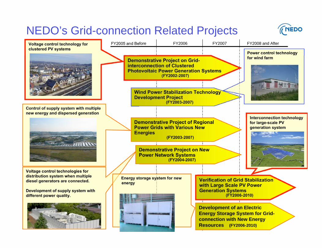
NEDO’s Grid-connection Related ProjectsVoltage control technology for
clustered PV systems
Control of supply system with multiple
new energy and dispersed generation
Voltage control technologies for
distribution system when multiple
diesel generators are connected.
Development of supply system with
different power quality.
Demonstrative Project on Grid-interconnection of ClusteredPhotovoltaic Power Generation Systems
(FY2002-2007)
Wind Power Stabilization TechnologyDevelopment Project
(FY2003-2007)
Demonstrative Project of RegionalPower Grids with Various NewEnergies
(FY2003-2007)
Demonstrative Project on NewPower Network Systems
(FY2004-2007)
Verification of Grid Stabilizationwith Large Scale PV PowerGeneration Systems
(FY2006-2010)
FY2006FY2005 and Before
Power control technology
for wind farm
Interconnection technology
for large-scale PV
generation system
Energy storage system for new
energy
Development of an Electric
Energy Storage System for Grid-
connection with New Energy
Resources (FY2006-2010)
FY2007 FY2008 and After
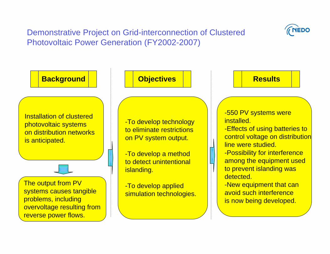
Demonstrative Project on Grid-interconnection of Clustered
Photovoltaic Power Generation (FY2002-2007)
Installation of clustered
photovoltaic systems
on distribution networks
is anticipated.
The output from PV
systems causes tangible
problems, including
overvoltage resulting from
reverse power flows.
-To develop technology
to eliminate restrictions
on PV system output.
-To develop a method
to detect unintentional
islanding.
-To develop applied
simulation technologies.
-550 PV systems were
installed.
-Effects of using batteries to
control voltage on distribution
line were studied.
-Possibility for interference
among the equipment used
to prevent islanding was
detected.
-New equipment that can
avoid such interference
is now being developed.
Background Objectives Results

Demonstrative Project on Grid-interconnection of Clustered
Photovoltaic Power Generation (FY2002-2007)
PV systems installed: 553
Total PV capacity: 2,129 kW
Avg. system capacity: 3.85 kW
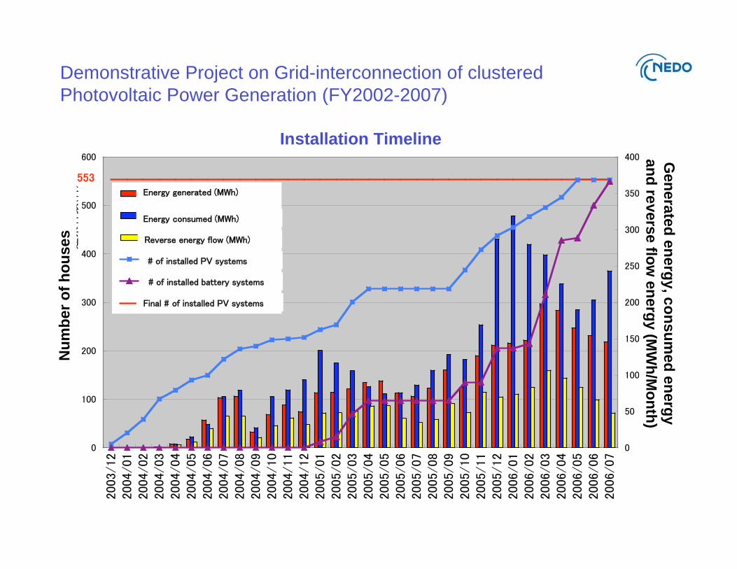
Demonstrative Project on Grid-interconnection of clustered
Photovoltaic Power Generation (FY2002-2007)
Nu
mb
er
of
ho
uses
Gen
era
ted
en
erg
y, c
on
su
med
en
erg
y
an
d re
vers
e flo
w e
nerg
y (M
Wh
/Mo
nth
)
Installation Timeline
Demonstrative Project on Grid-interconnection of Clustered
Photovoltaic Power Generation (FY2002-2007)
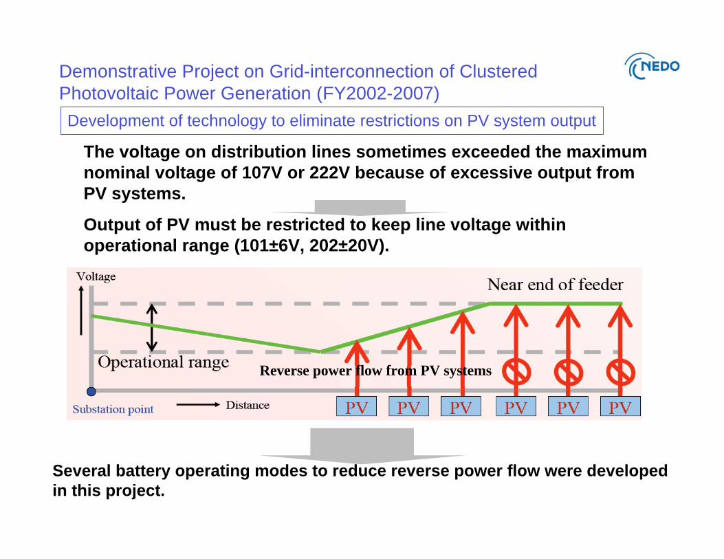
The voltage on distribution lines sometimes exceeded the maximum
nominal voltage of 107V or 222V because of excessive output from
PV systems.
Output of PV must be restricted to keep line voltage within
operational range (101±6V, 202±20V).
Several battery operating modes to reduce reverse power flow were developed
in this project.
Development of technology to eliminate restrictions on PV system output
Reverse power flow from PV systems
Demonstrative Project on Grid-interconnection of Clustered
Photovoltaic Power Generation (FY2002-2007)
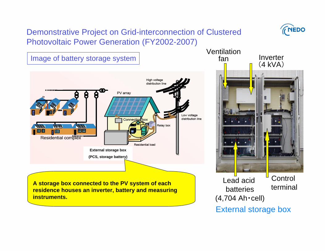
External storage box
(PCS, storage battery)
Inverter4 kVA
Lead acid
batteries
(4,704 Ah cell)
Ventilation fan
Control
terminal
External storage box
A storage box connected to the PV system of each
residence houses an inverter, battery and measuring
instruments.
Image of battery storage system
Demonstrative Project on Grid-interconnection of Clustered
Photovoltaic Power Generation (FY2002-2007)
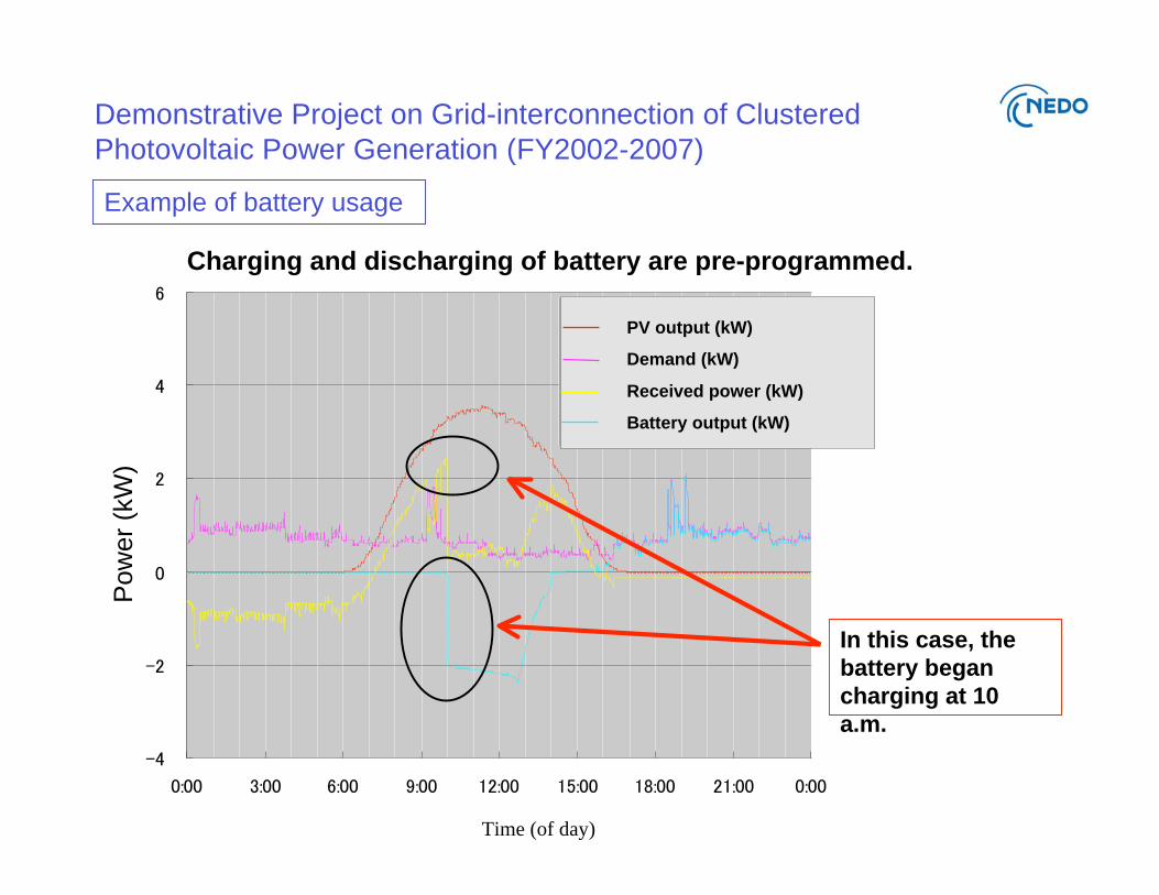
Charging and discharging of battery are pre-programmed.
In this case, the
battery began
charging at 10
a.m.
Example of battery usage
Pow
er
(kW
)
PV output (kW)
Demand (kW)
Received power (kW)
Battery output (kW)
Time (of day)
Demonstrative Project on Grid-interconnection of Clustered
Photovoltaic Power Generation (FY2002-2007)
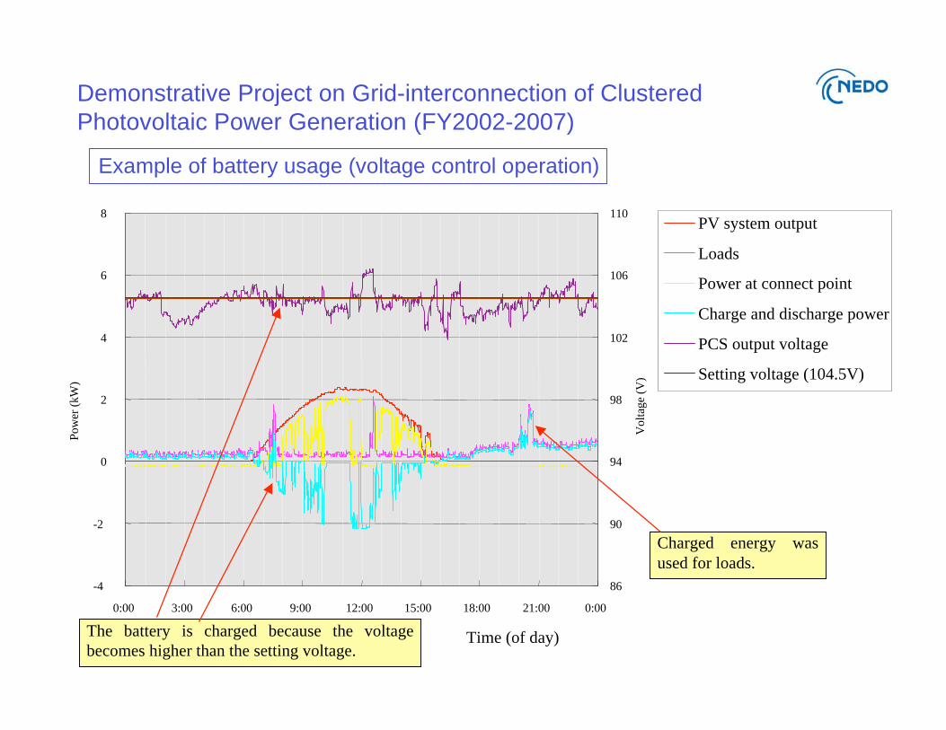
Example of battery usage (voltage control operation)
-4
-2
0
2
4
6
8
0:00 3:00 6:00 9:00 12:00 15:00 18:00 21:00 0:00
Pow
er (
kW
)
86
90
94
98
102
106
110
Volt
age
(V)
PV system output
Loads
Power at connect point
Charge and discharge power
PCS output voltage
Setting voltage (104.5V)
The battery is charged because the voltage
becomes higher than the setting voltage.
Charged energy was
used for loads.
Time (of day)
Demonstrative Project on Grid-interconnection of Clustered
Photovoltaic Power Generation (FY2002-2007)
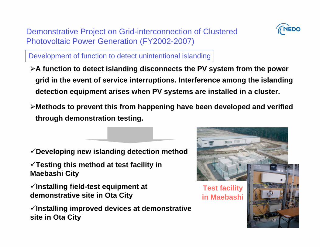
Development of function to detect unintentional islanding
A function to detect islanding disconnects the PV system from the power
grid in the event of service interruptions. Interference among the islanding
detection equipment arises when PV systems are installed in a cluster.
Methods to prevent this from happening have been developed and verified
through demonstration testing.
Developing new islanding detection method
Testing this method at test facility in
Maebashi City
Installing field-test equipment at
demonstrative site in Ota City
Installing improved devices at demonstrative
site in Ota City
Test facility
in Maebashi

Demonstrative Project on Grid-interconnection of Clustered
Photovoltaic Power Generation (FY2002-2007)
Concept for conflict-free islanding detection
A GPS signal is
used to
synchronize
active output
from PCSs
Demonstrative Project on Grid-interconnection of Clustered
Photovoltaic Power Generation (FY2002-2007)
Status of the project
(1) During the final stage of the project, we obtained several results.
An extensive amount of data on actual residential demand, PV output and battery
storage operation was collected.
Economic feasibility for introducing batteries was summarized.
New islanding detection method for clustered PV systems was developed.
A simulation method related to this project is being developed.
(2) Post-project
NEDO is planning to start technology development for an islanding detection
certification system for clustered generation systems.
We are able to disclose operating data to interested parties who are willing to sign a
non-disclosure.
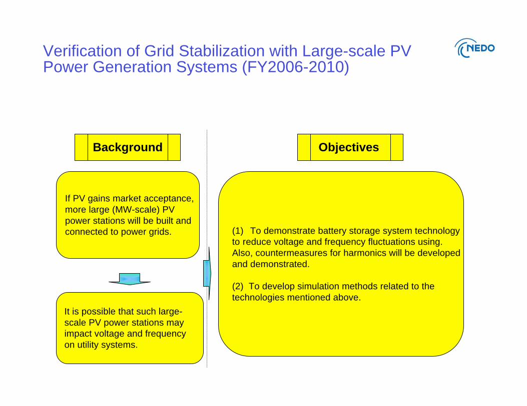
If PV gains market acceptance,
more large (MW-scale) PV
power stations will be built and
connected to power grids. (1) To demonstrate battery storage system technology
to reduce voltage and frequency fluctuations using.
Also, countermeasures for harmonics will be developed
and demonstrated.
(2) To develop simulation methods related to the
technologies mentioned above.
It is possible that such large-
scale PV power stations may
impact voltage and frequency
on utility systems.
Background Objectives
Verification of Grid Stabilization with Large-scale PVPower Generation Systems (FY2006-2010)
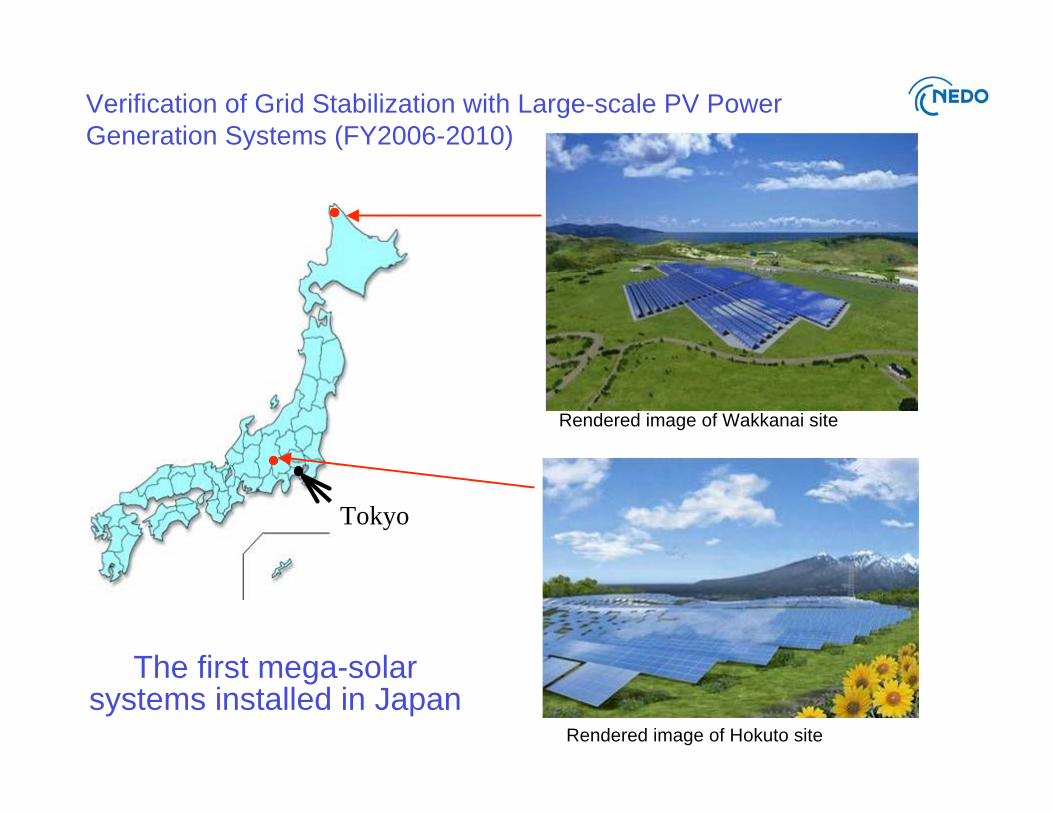
Verification of Grid Stabilization with Large-scale PV Power
Generation Systems (FY2006-2010)
Tokyo
Rendered image of Wakkanai site
Rendered image of Hokuto site
The first mega-solarsystems installed in Japan
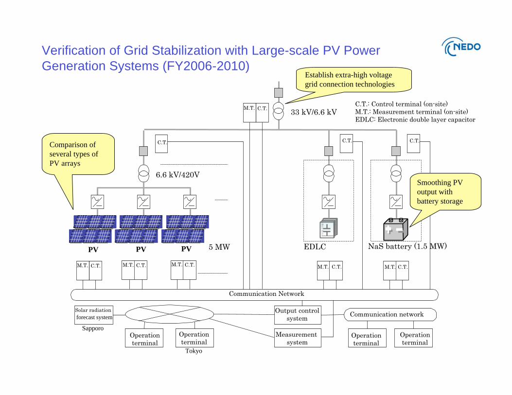
Verification of Grid Stabilization with Large-scale PV Power
Generation Systems (FY2006-2010)
NaS battery (1.5 MW)
C.T.: Control terminal (on-site)M.T.: Measurement terminal (on-site)EDLC: Electronic double layer capacitor
EDLC
Communication Network
Solar radiation
forecast system Communication network
33 kV/6.6 kV
6.6 kV/420V
5 MW
Output controlsystem
Measurement system
PV
M.T. C.T.
Operationterminal
M.T. C.T.
C.T. C.T. C.T.
Operationterminal
Operationterminal
Operationterminal
M.T. C.T. M.T. C.T.
PV PV
M.T. C.T. M.T. C.T.
Tokyo
Sapporo
Comparison of
several types of
PV arrays
Establish extra-high voltage
grid connection technologies
Smoothing PV
output with
battery storage

Verification of Grid Stabilization with Large-scale PV Power
Generation Systems (FY2006-2010)
–
NaS: 1.5 MW – 11.8 MWh
EDLC: 1.5 MW – 25 kWh
Energy storage
400 kW
(under development)
250 kW
(commercialized product)
PCS
66 kV transmission line33 kV transmission lineGrid connection
–Solar radiation forecastForecasting
Various advanced modulesCrystallineModule type
Max. 2 MW Max. 5 MWPV capacity
Hokuto CityWakkanai City
Mega-solar system comparison

Verification of Grid Stabilization with Large-scale PV Power
Generation Systems (FY2006-2010)
Wakkanai site
Hokuto site
2006 2007 2008 2009 2010
PV capacity (MW)80 kW
Mar. ’082.0 MW
Dec. ’08
4.0 MWOct. ’09
5.0 MW
NaS battery (MW)Jan. ’08
0.5 MW
Oct. ’08
1.5 MW
EDLC (MW)1.5 MW
Grid connectionMar. ’07
6.6 kV
Nov. ’07
33 kV
2006 2007 2008 2009 2010
PV capacity (MW)0.6 MW
Sep. ’09
2.0 MW
Grid connectionFeb. ’08
6.6 kV
Sep. ’09
66 kV
Feb. ’08
Mar. ’07
Verification of Grid Stabilization with Large-scale PV Power
Generation Systems (FY2006-2010)
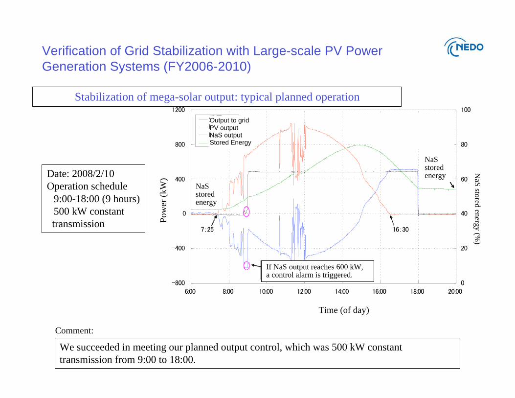
We succeeded in meeting our planned output control, which was 500 kW constant
transmission from 9:00 to 18:00.
Comment:
Date: 2008/2/10
Operation schedule
9:00-18:00 (9 hours)
500 kW constant
transmission Po
wer
(k
W)
Stored energy
NaSstoredenergy
NaSstoredenergy
If NaS output reaches 600 kW,a control alarm is triggered.
NaS
stored
energ
y (%
)
Stabilization of mega-solar output: typical planned operation
Output to gridPV outputNaS outputStored Energy
Time (of day)
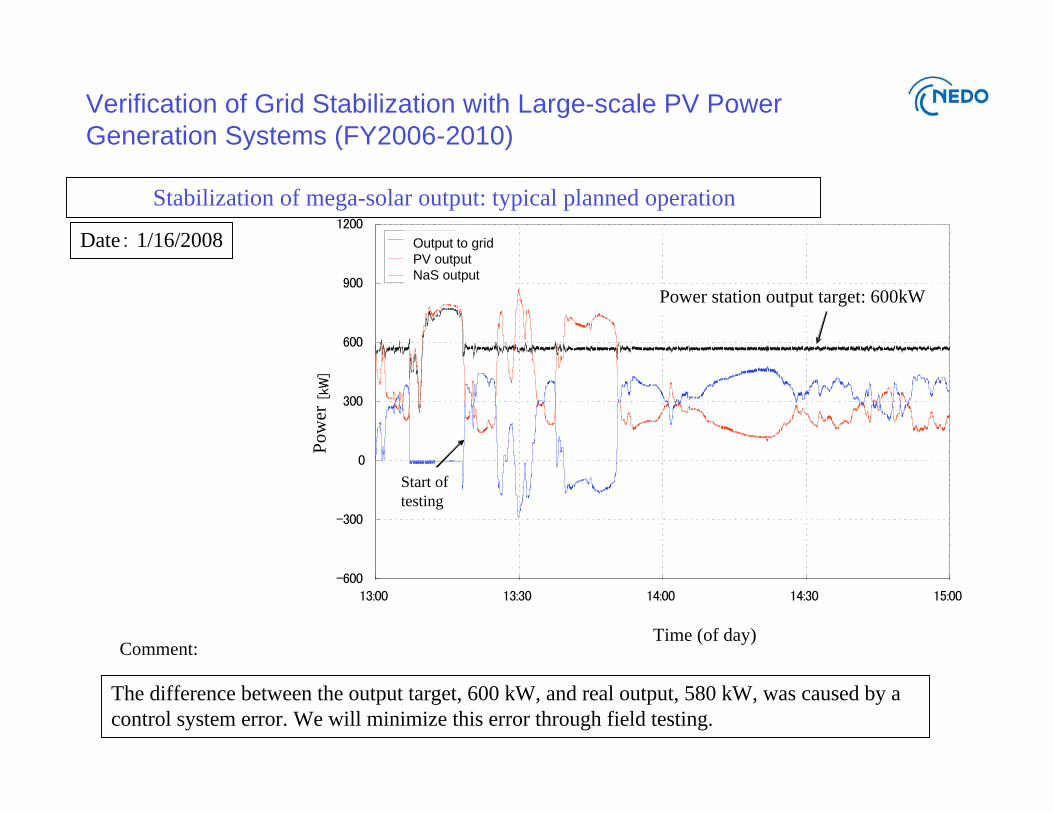
Verification of Grid Stabilization with Large-scale PV Power
Generation Systems (FY2006-2010)
Stabilization of mega-solar output: typical planned operation
The difference between the output target, 600 kW, and real output, 580 kW, was caused by a
control system error. We will minimize this error through field testing.
Comment:
Date 1/16/2008
Power station output target: 600kW
Output to grid
PV output
NaS output
Start of
testing
Po
wer
Time (of day)
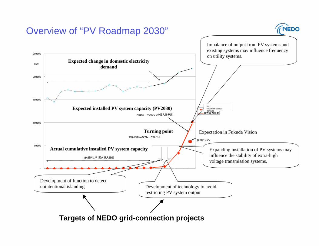
Overview of “PV Roadmap 2030”
Development of function to detect
unintentional islanding Development of technology to avoid
restricting PV system output
Expanding installation of PV systems may
influence the stability of extra-high
voltage transmission systems.
Targets of NEDO grid-connection projects
Imbalance of output from PV systems and
existing systems may influence frequency
on utility systems.
Turning point
Expected installed PV system capacity (PV2030)
Expectation in Fukuda Vision
Actual cumulative installed PV system capacity
Expected change in domestic electricity
demand
PVMaximum outputdemand
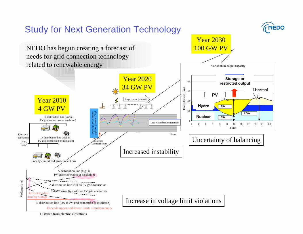
Study for Next Generation TechnologyYear 2030
100 GW PV
Storage or
restricted output
[s]Inte
rnal
ph
ase
dif
fere
nce
angle
s of
gen
erat
ors
[deg
]
A grid-
connection
accident occurs
( )
Increased instability
Uncertainty of balancing
Year 2020
34 GW PV
Year 2010
4 GW PV
A PV or
B PV or
Increase in voltage limit violations
NEDO has begun creating a forecast of
needs for grid connection technology
related to renewable energy
Distance from electric substations
Volt
age[
p.u
]
Exceeds upper and lower limits simultaneously
B distribution line with no PV grid connection
A distribution line with no PV grid connection
Difficult to adjust
delivery voltage
A distribution line (high in
PV grid connection or insolation)
Electrical
substation A distribution line (high in
PV grid connection or insolation)
B distribution line (low in
PV grid connection or insolation)
Locally centralized grid connections
B distribution line (low in PV grid connection or insolation)
Large current (unstable)
Loss of synchronism (unstable)
Hours
Variation in output capacity
Po
wer
dem
and
(G
W)
Time

Thank you for your attention!!