Embed Size (px)
Citation preview

PAPER • OPEN ACCESS
Negative refraction with tunable absorption in anactive dense gas of atomsTo cite this article: Peter P Orth et al 2013 New J. Phys. 15 013027
View the article online for updates and enhancements.
You may also likeTerahertz radiative coupling and dampingin multilayer grapheneP Bowlan, E Martinez-Moreno, K Reimannet al.
-
Physics of negative refractive indexmaterialsS Anantha Ramakrishna
-
Ultracold polar molecules as quditsRahul Sawant, Jacob A Blackmore, PhilipD Gregory et al.
-
This content was downloaded from IP address 64.229.84.59 on 06/02/2022 at 16:49

Negative refraction with tunable absorptionin an active dense gas of atoms
Peter P Orth1,2, Roman Hennig1, Christoph H Keitel1
and Jorg Evers1,3
1 Max-Planck-Institut fur Kernphysik, Saupfercheckweg 1,D-69117 Heidelberg, Germany2 Institute for Theory of Condensed Matter, Karlsruhe Institute of Technology(KIT), D-76131 Karlsruhe, GermanyE-mail: [email protected]
New Journal of Physics 15 (2013) 013027 (18pp)Received 17 October 2012Published 15 January 2013Online at http://www.njp.org/doi:10.1088/1367-2630/15/1/013027
Abstract. The applications of negative index materials (NIM) are currentlyseverely limited by absorption. Subsequent to improvements of metamaterialdesign, it has been suggested that dense gases of atoms could form NIM withnegligible loss. In such gases, the low absorption is facilitated by quantuminterference. In this paper, we show that additional gain mechanisms can be usedto tune and effectively remove absorption in a dense gas NIM. In our setup, theatoms are coherently prepared by control laser fields, and further driven by aweak incoherent pump field to induce gain. We employ nonlinear optical Blochequations to analyze the optical response. Metastable neon was identified as asuitable experimental candidate at infrared frequencies to implement a losslessactive negative index material.
3 Author to whom any correspondence should be addressed.
Content from this work may be used under the terms of the Creative Commons Attribution-NonCommercial-ShareAlike 3.0 licence. Any further distribution of this work must maintain attribution to the author(s) and the title
of the work, journal citation and DOI.
New Journal of Physics 15 (2013) 0130271367-2630/13/013027+18$33.00 © IOP Publishing Ltd and Deutsche Physikalische Gesellschaft
2
Contents
1. Introduction 22. Linear-response theory of a dense gas of five-level atoms 3
2.1. Five-level atoms and the role of applied light fields . . . . . . . . . . . . . . . 42.2. Linear response and the index of refraction n . . . . . . . . . . . . . . . . . . 52.3. Master equation for five-level atoms . . . . . . . . . . . . . . . . . . . . . . . 72.4. Nonlinear optical Bloch equations . . . . . . . . . . . . . . . . . . . . . . . . 8
3. Optical response for different atomic densities 103.1. Larger density N1 = 2.55 × 1017 cm−3 . . . . . . . . . . . . . . . . . . . . . . 103.2. Smaller density N2 = 5 × 1016 cm−3 . . . . . . . . . . . . . . . . . . . . . . . 123.3. Doppler broadening . . . . . . . . . . . . . . . . . . . . . . . . . . . . . . . . 15
4. Summary 17Acknowledgment 17References 18
1. Introduction
Over the last few years, tremendous progress has been accomplished in the field of negativerefractive index materials [1–6]. To a large extent, this progress was fueled by the ongoingminiaturization and optimization of metamaterials, which are artificial materials made ofstructures smaller than the wavelength of the probing light [6]. In most cases, however, negativerefraction is accompanied by a substantial amount of absorption, especially toward higherfrequencies. These losses typically occur since the refractive index becomes negative onlyclose to electromagnetic resonances where the absorption is high. As a result, the relevantfigure of merit (FOM), the ratio between the real and the imaginary part of the refractiveindex FOM = |Re(n)/Im(n)| for high-frequency metamaterials, is currently only of the orderof unity [7], restricting most of the possible applications [8–12]. It has been proposed anddemonstrated in proof-of-principle experiments to circumvent this limitation by implementinga gain mechanism into the medium [13–15]. Still, it remains challenging to achieve sufficientlylarge gain coefficients.
As an alternative approach, recently, dense gases of atoms have been proposed to achievea negative index of refraction without metamaterials [16–19]. In particular, it has been shownthat by reducing absorption via interference, negative refraction can be achieved over a certainspectral region with negligible absorption [18, 19]. The achievement of a negative index ofrefraction is further supported by a cross-coupling that allows to induce a magnetization by theelectric field component of the probe field [18–27]. Gases also naturally have a macroscopicextent in all spatial dimensions, unlike high-frequency metamaterials which typically areproduced layer by layer on a surface [28].
Here, we explore the possibility of implementing gain mechanisms in atomic gases toachieve a negative index of refraction with tunable absorption. In our setup, a dense gas ofatoms is exposed to control laser fields that create coherence between different internal atomicstates. Quantum interference effects reduce the absorption in the gas and an additional weakincoherent pumping field is used to render the system completely lossless: Im(n) = 0; or transferit into an active, amplifying state where Im(n) < 0. As our main result, we show that changing
New Journal of Physics 15 (2013) 013027 (http://www.njp.org/)
3
2p5(2P3/2)3s 2[3/2]−2
2p5(2P1/2)3s 2[1/2]−1
2p5(2P1/2)3d 2[3/2]−1
2p5(2P1/2)4p 2[1/2]+0
2p5(2P1/2)12s 2[1/2]−1
|1
|2
|3
|4
|5
Ea
Bb
Ec
Ed
Eb
Δ{
r34, r43
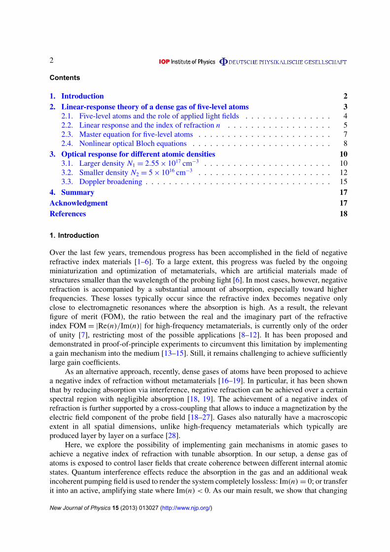
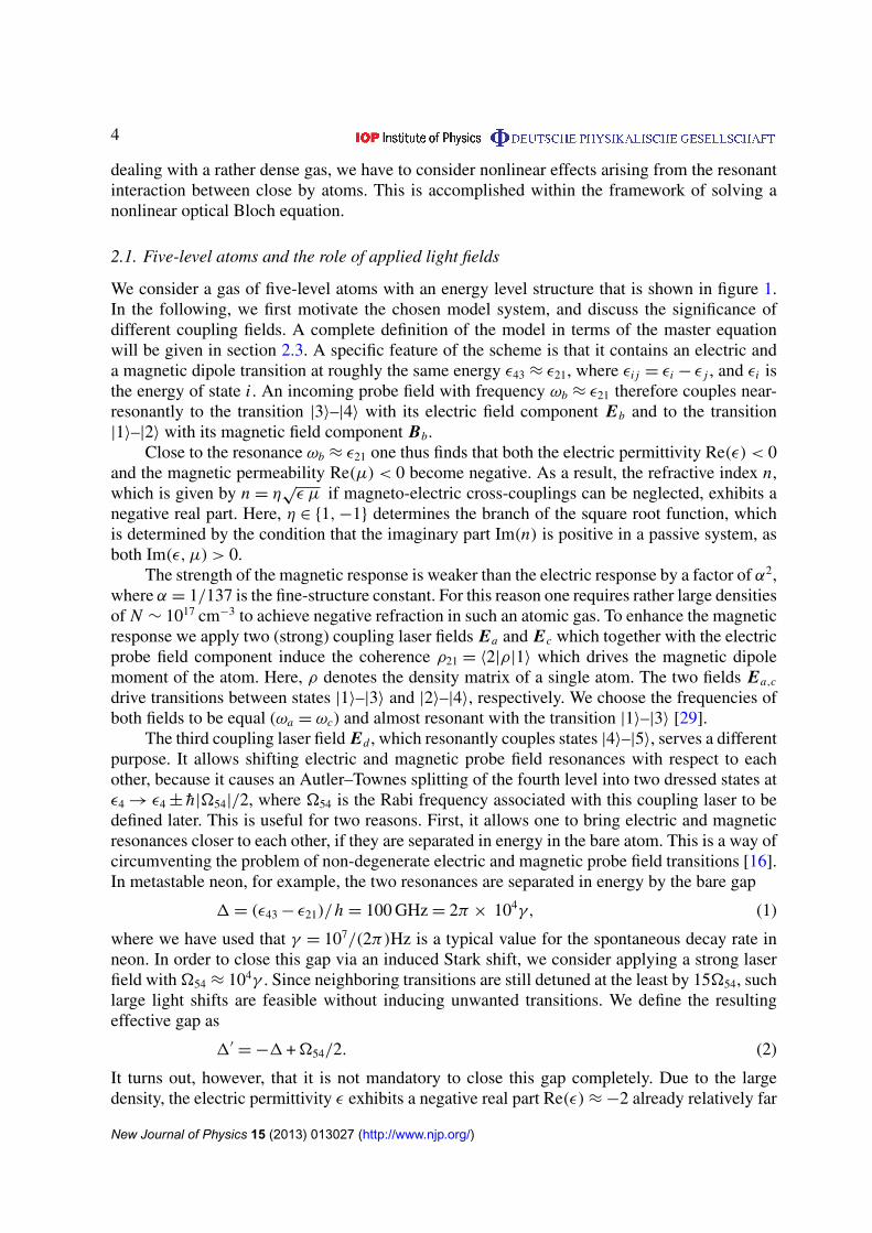
Figure 1. Five-level scheme with probe field with components Eb, Bb (red)and coupling fields Ea, Ec, Ed (blue) of frequencies ωb, ωa, ωc and ωd ,respectively. The electronic states in jL-coupling notation refer to thespecial case of metastable neon (http://physics.nist.gov/Pubs/AtSpec/ andhttp://physics.nist.gov/PhysRefData/), with the corresponding wavelengthsλb = 5.4 µm, λa = 704 nm, λc = 352 nm and λd = 1.05 µm. The magnetic andelectric probe field transitions |1〉–|2〉 (M1) and |3〉–|4〉 (E1) are energeticallydegenerate up to a small energy gap 1 = 3.33 cm−1
= 100 GHz. An incoherentlight field (black) acts as a pump rate r34, r43 between the states |3〉 and |4〉.
the intensity of the pumping field continuously allows for a controlled transition from a passiveto an active state.
The feasibility of our scheme is discussed for the case of a dense gas of metastableneon, where we find negative refraction to be in the infrared range at a wavelength of aboutλ = 5 µm. We explicitly demonstrate that our main results are robust under the effect of Dopplerbroadening, which occurs in a thermal gas. The required energy level scheme, depicted infigure 1, however, could be realized also in other solid state systems like doped semiconductorsor quantum dot arrays, or with different atomic species, where cold-atom realizations arepossible. This would significantly reduce the effect of Doppler broadening.
The remainder of this paper is structured as follows. In section 2, we explain how tocalculate the linear optical response of a dense gas of metastable neon atoms, and show howit allows for a negative index of refraction with tunable absorption. In section 3, we presentthe results for metastable neon at two different vapor densities. We also provide a detaileddiscussion on the effect of Doppler broadening on the thermal gas. In section 4, we summarizeour results.
2. Linear-response theory of a dense gas of five-level atoms
In this section, we introduce the energy level scheme of the atoms and the role of the appliedlight fields in achieving a negative refractive index with tunable absorption. Since we are
New Journal of Physics 15 (2013) 013027 (http://www.njp.org/)
4
dealing with a rather dense gas, we have to consider nonlinear effects arising from the resonantinteraction between close by atoms. This is accomplished within the framework of solving anonlinear optical Bloch equation.
2.1. Five-level atoms and the role of applied light fields
We consider a gas of five-level atoms with an energy level structure that is shown in figure 1.In the following, we first motivate the chosen model system, and discuss the significance ofdifferent coupling fields. A complete definition of the model in terms of the master equationwill be given in section 2.3. A specific feature of the scheme is that it contains an electric anda magnetic dipole transition at roughly the same energy ε43 ≈ ε21, where εi j = εi − ε j , and εi isthe energy of state i . An incoming probe field with frequency ωb ≈ ε21 therefore couples near-resonantly to the transition |3〉–|4〉 with its electric field component Eb and to the transition|1〉–|2〉 with its magnetic field component Bb.
Close to the resonance ωb ≈ ε21 one thus finds that both the electric permittivity Re(ε) < 0and the magnetic permeability Re(µ) < 0 become negative. As a result, the refractive index n,which is given by n = η
√ε µ if magneto-electric cross-couplings can be neglected, exhibits a
negative real part. Here, η ∈ {1, −1} determines the branch of the square root function, whichis determined by the condition that the imaginary part Im(n) is positive in a passive system, asboth Im(ε, µ) > 0.
The strength of the magnetic response is weaker than the electric response by a factor of α2,where α = 1/137 is the fine-structure constant. For this reason one requires rather large densitiesof N ∼ 1017 cm−3 to achieve negative refraction in such an atomic gas. To enhance the magneticresponse we apply two (strong) coupling laser fields Ea and Ec which together with the electricprobe field component induce the coherence ρ21 = 〈2|ρ|1〉 which drives the magnetic dipolemoment of the atom. Here, ρ denotes the density matrix of a single atom. The two fields Ea,c
drive transitions between states |1〉–|3〉 and |2〉–|4〉, respectively. We choose the frequencies ofboth fields to be equal (ωa = ωc) and almost resonant with the transition |1〉–|3〉 [29].
The third coupling laser field Ed , which resonantly couples states |4〉–|5〉, serves a differentpurpose. It allows shifting electric and magnetic probe field resonances with respect to eachother, because it causes an Autler–Townes splitting of the fourth level into two dressed states atε4 → ε4 ± h|�54|/2, where �54 is the Rabi frequency associated with this coupling laser to bedefined later. This is useful for two reasons. First, it allows one to bring electric and magneticresonances closer to each other, if they are separated in energy in the bare atom. This is a way ofcircumventing the problem of non-degenerate electric and magnetic probe field transitions [16].In metastable neon, for example, the two resonances are separated in energy by the bare gap
1 = (ε43 − ε21)/h = 100 GHz = 2π × 104γ, (1)
where we have used that γ = 107/(2π)Hz is a typical value for the spontaneous decay rate inneon. In order to close this gap via an induced Stark shift, we consider applying a strong laserfield with �54 ≈ 104γ . Since neighboring transitions are still detuned at the least by 15�54, suchlarge light shifts are feasible without inducing unwanted transitions. We define the resultingeffective gap as
1′= −1 + �54/2. (2)
It turns out, however, that it is not mandatory to close this gap completely. Due to the largedensity, the electric permittivity ε exhibits a negative real part Re(ε) ≈ −2 already relatively far
New Journal of Physics 15 (2013) 013027 (http://www.njp.org/)
5
away from the resonance [30]. More importantly, the states |2〉 and |3〉 are connected by a two-photon transition induced by the fields Ec and Eb, which becomes important only for non-zeroeffective gap frequencies 1′.
This two-photon transition is the motivation to apply an additional incoherent light fieldwhich is resonant with the transition |3〉–|4〉. It transfers population between the two levels withrates r34 = r43 = r . In combination with spontaneous emission from |4〉 to |2〉, it effectivelypumps population from state |3〉 into state |2〉. As soon as the population of state |2〉 exceedsthe one of state |3〉, i.e. for ρ22 > ρ33, the probe field Eb is amplified by means of this two-photon process. It is then more likely for the transition to occur in the direction |2〉 → |3〉 thanin the reverse direction. Since this direction involves the emission of a probe field photon, weobserve gain in the electric probe field component for ρ22 > ρ33. Choosing equal coupling laserfrequencies ωa = ωc ensures that this two-photon resonance is always located at the position ofa magnetic probe field resonance close to δ21 = 0. The two-photon virtual intermediate level isseparated from state |4〉 by the tunable effective gap 1′ defined in equation (2). For sufficientlylarge 1′, the two-photon transition will thus be the dominant process around δ21 ' 0. This isimportant, as it allows to obtain gain in the electric probe field component exactly at thosefrequencies where the magnetic response is strong.
2.2. Linear response and the index of refraction n
We now define the electromagnetic linear response functions and the index of refraction n.As stated above, negative refraction Re(n) < 0 requires that both the electric and the magneticcomponent of an electromagnetic probe wave couple near-resonantly to the system. We arethus interested in the linear response of the medium to a weak probe field of frequency ωb
with electric component Eb and magnetic field component Hb. The electric polarization P andmagnetization M induced in the medium at the frequency ωb are given by [20]
P(ωb) = χE E(ωb)Eb + ξE H (ωb)Hb/4π, (3a)
M(ωb) = χH H (ωb)Hb + ξH E(ωb)Eb/4π. (3b)
Here, χE E and χH H are the electric and magnetic susceptibilities, respectively, whereas ξE H andξH E are the so-called chirality coefficients that describe the cross-coupling between electric andmagnetic fields in a chiral medium such as our system. In general, all response functions aretensors.
We now bring the vector relations in equations (3) into a simpler scalar form, where theresponse functions reduce to complex scalars. To this end, we focus on a circularly polarizedprobe beam that propagates in the z-direction in the following. Its wavevector reads k = nk0ez
with k0 = 2π/λb. The electric and magnetic field components are given by
Eb =Eb
2e±1 e−iωbt + c.c. (4)
and Hb = ∓ie±1 e−iωbt Hb/2 + c.c. with polarization unit vectors that are defined as e±1= ∓ (ex ±
iey)/√
2. The two signs indicate the two circular polarizations σ±. The electric polarization thenbecomes
P(ωb) =P
2e±1 e−iωbt + c.c. (5)
New Journal of Physics 15 (2013) 013027 (http://www.njp.org/)
6
with amplitude
P = χE E Eb + ξE HiHb
4π. (6)
The real (imaginary) part of the susceptibility χE E describes the electric response in phase(out of phase) with the incoming probe field. The response from the cross-coupling adds tothe electric polarization via ξE H . Accordingly, we derive for the amplitude M of the inducedmagnetization M(ωb)=(∓i M
2 e±1 e−iωbt + c.c) the response relation
M = χH H Hb − iξH EEb
4π. (7)
It is useful to define the electric permittivity ε and the magnetic permeability µ as usual as
ε = 1 + 4πχE E , (8a)
µ = 1 + 4πχH H . (8b)
We emphasize that ε and µ are complex scalars in our situation, since we assume a circularlypolarized probe field, where magnetic and electric field components are only phase shifted toeach other.
We can now calculate the refractive index n, which depends on the probe wave polarization.For circular σ±-polarization, we obtain [19, 20]
n± = η
√εµ −
(ξE H + ξH E)2
4±
i
2(ξH E − ξE H ) . (9)
As before, η ∈ {1, −1} determines the branch of the square root function, which wedetermine as discussed in section 2.1. We note that in our system the chiralitiesturn out to be negligible compared to the direct response coefficients ε and µ. Therefractive index is therefore approximately given by n = η
√εµ, and thus is independent of
polarization.To find the electric polarization P(ωb) and magnetization M(ωb) induced in the atomic
gas, we have to calculate the electric and magnetic dipole moments of the atoms at the probefield frequency ωb. The total response of the medium is given by a superposition of theindividual responses of the atoms. These are determined by the steady-state density matrixρ of an atom in the driven laser field configuration of figure 1. Specifically, the steady-statecoherences ρ43 and ρ21 govern the induced polarization and magnetization at the probe fieldfrequency as
P = N (ρ43d34 + c.c.) , (10a)
M = N (ρ21µ12 + c.c.) , (10b)
where N is the density of atoms, and d34 = 〈3|d|4〉 (µ12 = 〈1|µ|2〉) is the expectation value ofthe electric (magnetic) dipole operator for the probe field transitions. We thus need to calculatethe steady-state value of the atomic density matrix elements ρ43 and ρ21, which is describednext.
New Journal of Physics 15 (2013) 013027 (http://www.njp.org/)
7
2.3. Master equation for five-level atoms
We now set up a master equation for the five-level atoms in the laser configuration of figure 1,which allows us to calculate the steady-state density matrix and thus the response of the medium.Since the density of the gas is rather large, we have to take into account nonlinearities arisingfrom a resonant atom–atom interaction.
In the setup of figure 1, the probe field couples to the transition |3〉–|4〉 with its electric fieldcomponent and to the transition |1〉–|2〉 with its magnetic field component. Coupling fields drivethe transitions |1〉–|3〉, |2〉–|4〉 and |4〉–|5〉. Without a probe field, the atom is in a superpositionof the states |1〉 and |3〉. In the presence of the probe field, the atom also evolves into the otherstates. The zero-order subspace {|1〉, |3〉} is also connected to the other states by the incoherentpump field r34.
The time evolution of a single such five-level atom with density matrix ρ is governed bythe master equation [31]
ρ =1
ih[H, ρ] −
∑j,k
γ jk
2( | j〉〈 j |ρ + ρ| j〉〈 j | − 2|k〉〈 j |ρ| j〉〈k| ) (11)
with the system Hamiltonian given by
H =
5∑j=1
ε j | j〉〈 j | −
{µ21 · BL e−iωbt
|2〉〈1| + d43 · EL e−iωbt|4〉〈3| +
h�31
2e−iωa t
|3〉〈1|
+h�42
2e−iωct
|4〉〈2| +h�54
2e−iωd t
|5〉〈4| + h.c.
}. (12)
Here, ε j is the energy of state | j〉 and the other terms describe the interaction with the laserfields in the long-wavelength and dipole approximations. The fields have frequencies ωn withn ∈ {a, b, c, d}. The laser detuning on transition |i〉–| j〉 reads
hδi j = hωi j + εi j (13)
with i, j ∈ {1, . . . , 5}, where ωi j=ωi−ω j and εi j = εi − ε j , and we have introduced the angularfrequencies
ω1 = ωc + ωd + ωb, (14a)
ω2 = ωc + ωd, (14b)
ω3 = ωb + ωc + ωd − ωa, (14c)
ω4 = ωd, (14d)
ω5 = 0. (14e)The electric control field components
Em =Em
2εm e−iωm t + c.c. (15)
with polarization vector εm (m ∈ {a, c, d}) give rise to the complex Rabi frequencies
�31 = (d31 · εa)Ea/h, (16a)
New Journal of Physics 15 (2013) 013027 (http://www.njp.org/)
8
�42 = (d42 · εc)Ec/h, (16b)
�54 = (d54 · εd)Ed/h, (16c)
where d i j = 〈i |d| j〉 is the electric dipole operator between states |i〉 and | j〉. In the following,all control Rabi frequencies are taken to be real.
It is important to note that the Hamiltonian equation (12) contains instead of the externalprobe fields Eb, Hb the actual local fields EL, BL inside the medium. These containcontributions from the surrounding atoms in the medium as described by the polarization Pand magnetization M. The corresponding Rabi frequencies are thus defined as
�43 = (d43 · εb)EL/h, (17a)
�21 = (µ21 · εb)BL/h. (17b)
The local and external fields will be related to each other via the Lorentz–Lorenz relation in thenext section.
The second part of equation (11) describes spontaneous decay and decoherence arising dueto elastic collisions. The decay rate on transition |i〉 → | j〉 is denoted by γi j and set to γi j = γ if|i〉 → | j〉 is electric dipole allowed (E1) and set to γi j = α2γ for metastable E2, M1 transitions,where α = 1/137 is the fine-structure constant. To model elastic collisions, we add an effectivedephasing constant γC to the decay rates of the off-diagonal density matrix elements ρ jk inequation (11), such that they read
γ jk =
∑l
(γ jl + γkl)/2 + γC (18)
for j 6= k ∈ {1, . . . , 5}. In our numerical calculations, we set γC = γ .
2.4. Nonlinear optical Bloch equations
As already mentioned, the Hamiltonian equation (12) contains the actual local fields insidethe medium, whereas the medium response equation (3) is formulated in terms of the externalprobe fields Eb, Hb. It turns out that atom densities exceeding N ∼ 1016 cm−3 are required toobtain negative refraction, meaning that many particles are found in a cubic wavelength volumeNλ3
b � 1. Then, the local probe fields EL, HL experienced by the atoms may considerablydeviate from the externally applied probe fields Eb, Hb in free space, since they containcontributions from neighboring atoms. Therefore, single-atom results for ρ43 and ρ21 cannotdescribe the system and thus are not shown here.
Different approaches have been proposed in the literature to solve this problem. Oneapproach, which is expected to be valid for moderate densities, consists of expanding the steady-state density matrix elements ρ21 and ρ43 to linear order in the local fields EL, HL to obtain themedium polarization and magnetization. Then, the local and external fields are related by theLorentz–Lorenz (LL) formulae [30, 32]
EL = Eb +4π
3P, (19a)
New Journal of Physics 15 (2013) 013027 (http://www.njp.org/)
9
HL = Hb +4π
3M, (19b)
where we note that HL = BL in our units.Here, we use an alternative method. We relate the local fields via the LL-relations to the
external fields already in the Hamiltonian in equation (11). The corrections by the inducedpolarization P and magnetization M render the master equation nonlinear, since P and M givenin equation (10a) itself depend on ρ [33]. Specifically, we obtain the complex Rabi frequencies
�43 = (d43 · εb)EL/h = wEγ +8π Nd2
43
3hρ43, (20a)
�21 = (µ21 · εb)HL/h = wHγ +8π Nµ2
21
3hρ21, (20b)
where d43 = |d43| and µ21 = |µ21|. We have used that the local electric field amplitudereads EL = Eb + 4π P/3 with P=2N ρ43d34 and slowly varying ρ43=ρ43 eiωbt as follows fromequations (5) and (10a). In the same way, we find that BL = HL = Hb + 4π M/3 withM=2N ρ21µ12 and ρ21=ρ21 eiωbt . We have also defined the small and real expansion parameters
wE =d43 Eb
hγ� 1, (21a)
wH =µ21 Hb
hγ� 1. (21b)
An expansion in the weak external fields Eb, Hb is possible, and in the framework of the LL-formulas the local field effects are treated without approximations. Since the master equationbecomes nonlinear, however, one typically requires a numerical analysis. Interestingly, thesenonlinearities can have an influence already at low probe field strengths [34].
To find the linear response coefficients χαα and ξαβ (α, β ∈ {E, H}) introduced inequations (3), we numerically integrate the nonlinear differential equations of motion (11)using a standard Runge–Kutta-like algorithm [35] until the system has reached its steady state.This is done for a number of different electric field amplitudes Eb, holding the magnetic fieldamplitude Hb fixed. Linear regression of the relevant coherences ρ21, ρ43 as a function of Eb
allows to extract the response coefficients χαα and ξαβ as slope mα and y-axis intercept bα fromequations (3). We note again that in the case of a circularly polarized probe field, these equationsdescribe scalar relations. In the following, we choose Eb ∼ e−1 and thus Hb ∼ ie−1.
The response functions χEE and ξEH are obtained from the electric polarization
P =P
2εb e−iωbt + c.c. = N
(ρ43 e−iωbt d34 + c.c.
), (22)
where ρ43=ρ43 eiωbt is the slowly varying part of the coherence. We find that
P
2= N ρ43d34 = χE E
Eb
2+ ξE H
iHb
8π(23)
and thus
ρ43 = χE Ehγ
2Nd234
wE + ξE Hihγ
8π Nd34µ21wH (24)
New Journal of Physics 15 (2013) 013027 (http://www.njp.org/)
10
with the small expansion parameters defined in equations (21). Solving the nonlinear masterequation (11) for different values of wE keeping wH fixed, we calculate ρ43=m EwE + bE andthus
χE E =2Nd2
34
hγm E =
3Nλ3b
16π 3m E , (25a)
ξE H = −i8π Nd34µ21
hγwHbE = −i
3Nαλ3b
4π 2wHbE . (25b)
Here, we have used that the dipole moments di j and µi j can be evaluated via the respective
spontaneous decay rates as√
3γi j hc3/(4ω3i j). Analogously, using
iM
2= iN ρ21µ12 = χH H
iHb
2+ ξH E
Eb
8π, (26)
one obtains the response coefficients for the magnetization from ρ21=m HwE + bH as
χH H =3Nα2λ3
b
16π 3wHbH , (27a)
ξH E = i3Nαλ3
b
4π2m H . (27b)
It turns out that only the chirality coefficients ξαβ depend on the relative phase of the appliedlaser fields in the closed loop of the atomic level structure. Since they are typically muchsmaller than the direct coefficients ε and µ in our setup, however, they do not contributesignificantly to the index of refraction. Still, in our calculations we average over this phaseto simulate an experiment without phase control, which effectively reduces the magnitudeof ξE H and ξH E almost to zero. This is in stark contrast to other proposals where negativerefraction crucially relies on the control of this relative phase, since it emerges from the chiralitycoefficients [18, 27].
3. Optical response for different atomic densities
In the following, we present results for two different parameter sets. The main differenceis the atomic vapor density, which we choose N1 = 2.55 × 1017 cm−3 in the first and N2 =
5 × 1016 cm−3 in the second set of parameters. We note that the results are invariant under properrescaling of both density and probe wavelength such that the product Nλ3
b remains invariant (seeequations (25) and (27)). Here, we set λb = 5 µm, which corresponds to metastable neon, butsmaller densities are sufficient in a system with larger λb.
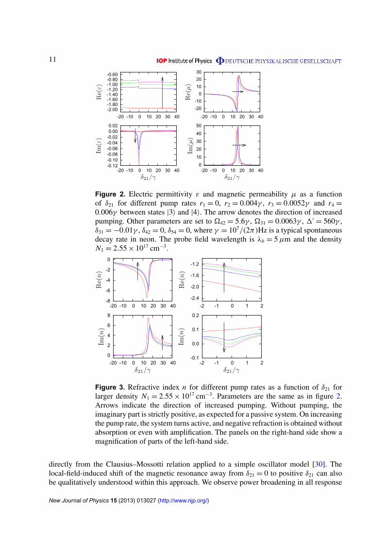
3.1. Larger density N1 = 2.55 × 1017 cm−3
In figure 2, the permittivity ε and the permeability µ of the medium are shown as a functionof the probe field detuning from the magnetic resonance δ21. The resulting refractive index ncan be seen in figure 3. Without incoherent pumping the system is passive and thus ε, µ andn have a positive imaginary part, i.e. the medium absorbs. Whereas absorption is small forthe electric response due to local field effects [30], the losses are significant in the magneticcomponent. The fact that Re(ε) ≈ −2 and the electric losses are small Im(ε) ∼ 1/N follows
New Journal of Physics 15 (2013) 013027 (http://www.njp.org/)
11
-2.00-1.80-1.60-1.40-1.20-1.00-0.80-0.60
-20 -10 0 10 20 30 40
-0.12-0.10-0.08-0.06-0.04-0.020.000.02
-20 -10 0 10 20 30 40
-20
-10
0
10
20
30
-20 -10 0 10 20 30 40
0
10
20
30
40
50
-20 -10 0 10 20 30 40
Re(ε)
Im(ε)
Re(μ)
Im(μ)
δ21/γδ21/γ
Figure 2. Electric permittivity ε and magnetic permeability µ as a functionof δ21 for different pump rates r1 = 0, r2 = 0.004γ , r3 = 0.0052γ and r4 =
0.006γ between states |3〉 and |4〉. The arrow denotes the direction of increasedpumping. Other parameters are set to �42 = 5.6γ , �31 = 0.0063γ , 1′
= 560γ ,δ31 = −0.01γ , δ42 = 0, δ54 = 0, where γ = 107/(2π)Hz is a typical spontaneousdecay rate in neon. The probe field wavelength is λb = 5 µm and the densityN1 = 2.55 × 1017 cm−3.
-8
-6
-4
-2
0
-20 -10 0 10 20 30 40
0
2
4
6
8
-20 -10 0 10 20 30 40
-2.4
-2.0
-1.6
-1.2
-2 -1 0 1 2
-0.1
0.0
0.1
0.2
-2 -1 0 1 2
Re(n)
Re(n)
Im(n)
Im(n)
δ21/γδ21/γ
Figure 3. Refractive index n for different pump rates as a function of δ21 forlarger density N1 = 2.55 × 1017 cm−3. Parameters are the same as in figure 2.Arrows indicate the direction of increased pumping. Without pumping, theimaginary part is strictly positive, as expected for a passive system. On increasingthe pump rate, the system turns active, and negative refraction is obtained withoutabsorption or even with amplification. The panels on the right-hand side show amagnification of parts of the left-hand side.
directly from the Clausius–Mossotti relation applied to a simple oscillator model [30]. Thelocal-field-induced shift of the magnetic resonance away from δ21 = 0 to positive δ21 can alsobe qualitatively understood within this approach. We observe power broadening in all response
New Journal of Physics 15 (2013) 013027 (http://www.njp.org/)
12
-2
-1
0
1
2
3
4
-20 -15 -10 -5 0 5 10 15
FOM/10
Im(n)
Re(n)
δ21/γ
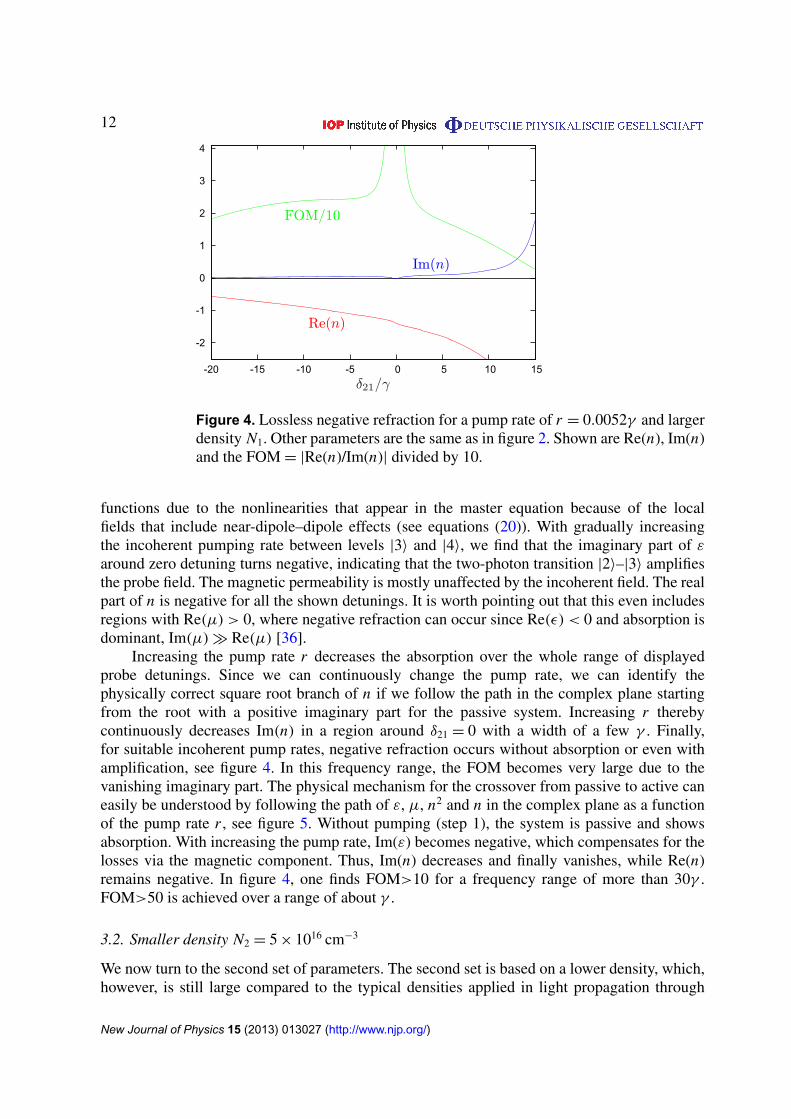
Figure 4. Lossless negative refraction for a pump rate of r = 0.0052γ and largerdensity N1. Other parameters are the same as in figure 2. Shown are Re(n), Im(n)and the FOM = |Re(n)/Im(n)| divided by 10.
functions due to the nonlinearities that appear in the master equation because of the localfields that include near-dipole–dipole effects (see equations (20)). With gradually increasingthe incoherent pumping rate between levels |3〉 and |4〉, we find that the imaginary part of ε
around zero detuning turns negative, indicating that the two-photon transition |2〉–|3〉 amplifiesthe probe field. The magnetic permeability is mostly unaffected by the incoherent field. The realpart of n is negative for all the shown detunings. It is worth pointing out that this even includesregions with Re(µ) > 0, where negative refraction can occur since Re(ε) < 0 and absorption isdominant, Im(µ) � Re(µ) [36].
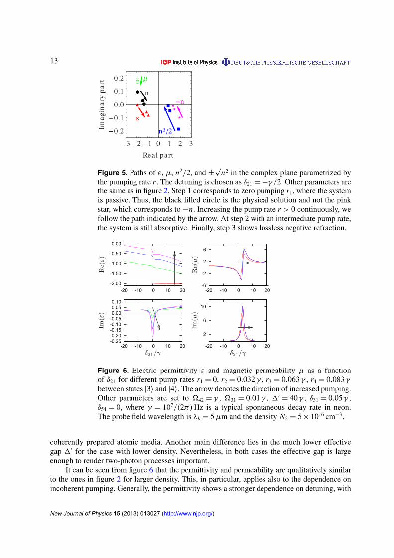
Increasing the pump rate r decreases the absorption over the whole range of displayedprobe detunings. Since we can continuously change the pump rate, we can identify thephysically correct square root branch of n if we follow the path in the complex plane startingfrom the root with a positive imaginary part for the passive system. Increasing r therebycontinuously decreases Im(n) in a region around δ21 = 0 with a width of a few γ . Finally,for suitable incoherent pump rates, negative refraction occurs without absorption or even withamplification, see figure 4. In this frequency range, the FOM becomes very large due to thevanishing imaginary part. The physical mechanism for the crossover from passive to active caneasily be understood by following the path of ε, µ, n2 and n in the complex plane as a functionof the pump rate r , see figure 5. Without pumping (step 1), the system is passive and showsabsorption. With increasing the pump rate, Im(ε) becomes negative, which compensates for thelosses via the magnetic component. Thus, Im(n) decreases and finally vanishes, while Re(n)remains negative. In figure 4, one finds FOM>10 for a frequency range of more than 30γ .FOM>50 is achieved over a range of about γ .
3.2. Smaller density N2 = 5 × 1016 cm−3
We now turn to the second set of parameters. The second set is based on a lower density, which,however, is still large compared to the typical densities applied in light propagation through
New Journal of Physics 15 (2013) 013027 (http://www.njp.org/)
13
µ
n
n² 2
n
3 2 1 0 1 2 3
0.2
0.1
0.0
0.1
0.2
Real part
Imag
inar
yp
art
Figure 5. Paths of ε, µ, n2/2, and ±√
n2 in the complex plane parametrized bythe pumping rate r . The detuning is chosen as δ21 = −γ /2. Other parameters arethe same as in figure 2. Step 1 corresponds to zero pumping r1, where the systemis passive. Thus, the black filled circle is the physical solution and not the pinkstar, which corresponds to −n. Increasing the pump rate r > 0 continuously, wefollow the path indicated by the arrow. At step 2 with an intermediate pump rate,the system is still absorptive. Finally, step 3 shows lossless negative refraction.
-2.00
-1.50
-1.00
-0.50
0.00
-20 -10 0 10 20
-0.25-0.20-0.15-0.10-0.050.000.050.10
-20 -10 0 10 20
-6
-2
2
6
-20 -10 0 10 20
2
6
10
-20 -10 0 10 20
Re(ε)
Im(ε)
Re(μ)
Im(μ)
δ21/γδ21/γ
Figure 6. Electric permittivity ε and magnetic permeability µ as a functionof δ21 for different pump rates r1 = 0, r2 = 0.032 γ , r3 = 0.063 γ , r4 = 0.083 γ
between states |3〉 and |4〉. The arrow denotes the direction of increased pumping.Other parameters are set to �42 = γ , �31 = 0.01 γ , 1′
= 40 γ , δ31 = 0.05 γ ,δ54 = 0, where γ = 107/(2π) Hz is a typical spontaneous decay rate in neon.The probe field wavelength is λb = 5 µm and the density N2 = 5 × 1016 cm−3.
coherently prepared atomic media. Another main difference lies in the much lower effectivegap 1′ for the case with lower density. Nevertheless, in both cases the effective gap is largeenough to render two-photon processes important.
It can be seen from figure 6 that the permittivity and permeability are qualitatively similarto the ones in figure 2 for larger density. This, in particular, applies also to the dependence onincoherent pumping. Generally, the permittivity shows a stronger dependence on detuning, with
New Journal of Physics 15 (2013) 013027 (http://www.njp.org/)
14
-3
-2
-1
0
-10 -5 0 5 10
0
2
4
-10 -5 0 5 10
-3.0
-2.0
-1.0
0.0
-2 -1 0 1 2
-0.5
0.0
0.5
1.0
1.5
-2 -1 0 1 2Re(n)
Re(n)
Im(n)
Im(n)
δ21/γδ21/γ
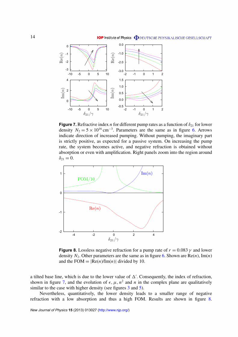
Figure 7. Refractive index n for different pump rates as a function of δ21 for lowerdensity N2 = 5 × 1016 cm−3. Parameters are the same as in figure 6. Arrowsindicate direction of increased pumping. Without pumping, the imaginary partis strictly positive, as expected for a passive system. On increasing the pumprate, the system becomes active, and negative refraction is obtained withoutabsorption or even with amplification. Right panels zoom into the region aroundδ21 = 0.
-2
-1
0
1
-4 -2 0 2 4
FOM/10Im(n)
Re(n)
δ21/γ
Figure 8. Lossless negative refraction for a pump rate of r = 0.083 γ and lowerdensity N2. Other parameters are the same as in figure 6. Shown are Re(n), Im(n)and the FOM = |Re(n)/Im(n)| divided by 10.
a tilted base line, which is due to the lower value of 1′. Consequently, the index of refraction,shown in figure 7, and the evolution of ε, µ, n2 and n in the complex plane are qualitativelysimilar to the case with higher density (see figures 3 and 5).
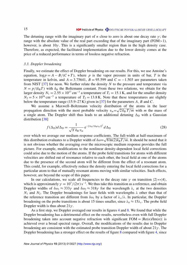
Nevertheless, quantitatively, the lower density leads to a smaller range of negativerefraction with a low absorption and thus a high FOM. Results are shown in figure 8.
New Journal of Physics 15 (2013) 013027 (http://www.njp.org/)
15
The detuning range with the imaginary part of n close to zero is about one decay rate γ ; therange with the absolute value of the real part exceeding that of the imaginary part (FOM>1),however, is about 10γ . This is a significantly smaller region than in the high density case.Therefore, as expected, the facilitated implementation due to the lower density comes at theprice of a reduced performance in terms of lossless negative refraction.
3.3. Doppler broadening
Finally, we estimate the effect of Doppler broadening on our results. For this, we use Antoine’sequation, logp = A − B/(C + T ), where p is the vapor pressure in units of bar, T is thetemperature in kelvin, and A = 3.75641, B = 95.599 and C = −1.503 are parameters takenfrom NIST [37] for neon. We further relate the density N to the pressure and temperature viaN = p/(kBT ) with kB the Boltzmann constant. From these two relations, we obtain for thelarger density N1 = 2.55 × 1017 cm−3 a temperature of T1 = 15.1 K, and for the smaller densityN2 = 5 × 1016 cm−3 a temperature of T2 = 13.8 K. Note that these temperatures are slightlybelow the temperature range (15.9–27 K) given in [37] for the parameters A, B and C .
We assume a Maxwell–Boltzmann velocity distribution of the atoms in the laserpropagation direction with the most probable velocity vm=
√2 kB T/m with m the mass of
a single atom. The Doppler shift thus leads to an additional detuning 1D with a Gaussiandistribution [38]
f (1D)d1D =1
√π kB vm
e−[1D/(kBvm)]2d1D (28)
over which we average our medium response coefficients. The full-width at half-maximum ofthis distribution evaluates to a Doppler width of δω=
√8 ln(2)kBT/m. It should be noted that it
is not obvious whether the averaging over the microscopic medium response provides the fullpicture. For example, modifications to the nonlinear density-dependent local field correctionscould arise due to the motion of the atoms. If the probe field transitions for atoms with differentvelocities are shifted out of resonance relative to each other, the local field at one of the atomsdue to the presence of the second atom will be different from the effect of a resonant atom.This could, for example, effectively reduce the density entering the local field corrections for aparticular atom to that of mutually resonant atoms moving with similar velocities. Such effects,however, are beyond the scope of this paper.
In our calculations, we scale all frequencies to the decay rate γ on transition |2〉↔|4〉,which is approximately γ = 107/(2π) s−1. We thus take this transition as a reference, and obtainDoppler widths of δω1 ≈ 333γ and δω2 ≈ 318γ for the wavelength λc at the two densitiesN1 and N2. The Doppler broadenings for laser fields with wavelengths λ other than that ofthe reference transition are different from δωi by a factor of λc/λ. In particular, the Dopplerbroadening on the probe transitions is about 15 times smaller, since λb ≈ 15λc. The probe fieldDoppler width is thus about 21γ .
As a first step, we Doppler averaged our results in figures 4 and 8. We found that while theDoppler broadening has a detrimental effect on the results, nevertheless even with full Dopplerbroadening taken into account negative refraction with significant FOM = |Re(n)/Im(n)| isachieved over a broad spectral range. Overall, the modifications of the results due to Dopplerbroadening are consistent with the estimated probe transition Doppler width of about 21γ . TheDoppler broadening has a stronger effect on the results of figure 8 compared with figure 4, since
New Journal of Physics 15 (2013) 013027 (http://www.njp.org/)

16
-4
-3
-2
-1
0
1
2
3
4
5
-50 -40 -30 -20 -10 0 10 20 30 40
FOM/10
Re(n)
(iii)
(i)
(ii)
(i)
(ii) (iii)
δ21/γ
Figure 9. Effect of Doppler broadening. The curves in the upper half show theFOM = |Re(n)/Im(n)| divided by 10. The curves in the lower half show the realpart of the index of refraction. (i) Results without Doppler broadening for thepassive system. (ii) Results with Doppler broadening δω1 ≈ 333γ taken intoaccount for the passive system. (iii) The figure shows Doppler broadened resultsfor the active case with an incoherent pump rate r = 0.164γ between states |3〉
and |4〉. The other parameters are �42 = 28γ , 1′= 150 γ , δ54 = 0. The probe
field wavelength is λ = 5 µm and the density 2.55 × 1017 cm−3. The couplingfield �31 has been replaced by an incoherent pump field between |1〉 and |3〉
with rate r13 = 4 × 10⁻⁵.
the range of probe field detunings over which negative refraction is observed is lower in thiscase.
But there are important differences compared with the results without Doppler averaging.Due to the different wavelength on the various transitions, the two-photon resonance betweenstates |2〉 and |3〉 via state |4〉 occurs at different probe field detunings for different atomvelocities, such that its effect is reduced in the Doppler averaging. Also, we found that for theparameters of figures 4 and 8, only atoms in a certain velocity range exhibit negative refraction.Thus, the Doppler averaged result contains contributions, both with negative and positive indexof refraction. The optimum incoherent pump rates to eliminate absorption depend on the atomvelocity as well. Finally, since the linewidth of the dipole-forbidden transition between |1〉 and|3〉 is suppressed by α2, already small Doppler shifts detune the pump field �31 strong enoughto significantly change the medium response to the electric probe field component. In effect, theDoppler averaged results have a more involved dependence on the various system parameterscompared with the non-averaged results, and a straightforward enhancement of the results byincoherent pump fields becomes more challenging with increasing Doppler width.
Nevertheless, we found that the concept of using active media to improve the performanceof atomic negative refractive index media can also be applied in Doppler broadened vapors. Forthis, we replaced the coherent pumping �31 by a broadband incoherent pump field between |1〉
and |3〉, such that the electric response becomes less dependent on the Doppler shift. Resultsare shown in figure 9 for slightly adjusted control field parameters, but with the same densityas in figure 4. The two curves (i) show the real part of the index of refraction n (the lower halfof the figure) and the FOM divided by 10 (FOM/10, upper half) in the passive medium without
New Journal of Physics 15 (2013) 013027 (http://www.njp.org/)
17
Doppler broadening. It can be seen that already in this passive case negative refraction withFOM of more than 20 can be achieved over a spectral range of several γ . The curves (ii) show thecorresponding results with full Doppler broadening. Whereas the system still exhibits negativerefraction, the maximum FOM is reduced to about eight due to the averaging. But, as shownin curves (iii), rendering the Doppler broadened system active by applying an incoherent pumpfield between states |3〉 and |4〉 leads to significant enhancement of the FOM, which in this caseapproaches 100. Interestingly, for the case with Doppler broadening, the FOM and the overallperformance are not monotonically improved with increasing the incoherent pump rate. Rather,increasing the pump rate first worsens the results, and only toward slightly higher pump rates itleads to a strong increase in the FOM as shown in figure 9. This more complicated dependenceagain arises from the averaging of the different results for the various atom velocities.
Our estimates above apply to a thermal gas vapor, which leads to rather large Dopplerwidths. Alternative implementations such as in ultracold gases, solid-state quantum optics orwith Doppler-free laser configurations in related level structures could lead to significantly lowerDoppler widths even at high atom densities. Interestingly, we found that for some parameters,moderate Doppler broadening can even lead to an enhancement of the FOM compared with thecase without Doppler broadening. This again points to the rich interplay between incoherentpump, Doppler broadening and medium response, such that independent control over densityand Doppler broadening would certainly be desirable. In any case, we can conclude from ouranalysis that the general concept of significantly improving the performance of a dense gas ofatoms as a negative refractive index medium by rendering it active via the application of suitablepump fields proves beneficial also for the Doppler broadened case in thermal vapors.
4. Summary
We have predicted negative refraction with adjustable loss in a dense gas of atoms. A possibleexperimental realization of our system is a thermal gas of metastable neon atoms, where negativerefraction occurs at an infrared wavelength of λ = 5 µm. Employing the transition to an activemedium by means of an incoherent pumping field allows to change between a system withpositive and negative imaginary parts of the refractive index while keeping the real part of theindex of refraction negative. It should be noted, however, that turning the gas into an activemedium can render it unstable [39, 40].
One of the main advantages of our setup is that the transition from absorptive tolossless to amplifying is externally tunable by a small incoherent light field. In particular,this allows to study the behavior of a negative refractive medium close to the active-to-passivethreshold [13–15]. We have explicitly shown that our main results are robust under the effectof Doppler broadening in a thermal gas of neon. Due to its wide tunability and control, oursystem is not only interesting from a proof-of-principle point of view, but also promises theenhancement of optical effects which are severely degraded by losses accompanying negativerefraction in current metamaterials.
Acknowledgment
The Young Investigator Group of PPO received financial support from the ‘Concept forthe Future’ of the Karlsruhe Institute of Technology within the framework of the GermanExcellence Initiative.
New Journal of Physics 15 (2013) 013027 (http://www.njp.org/)
18
References
[1] Veselago V G 1968 Sov. Phys.—Usp. 10 509[2] Veselago V G and Narimanov E E 2006 Nature Mater. 5 759[3] Shalaev V M 2007 Nature Photon. 1 41[4] Chen H, Chan C T and Sheng P 2010 Nature Mater. 9 387[5] McPhedran R C, Shadrivov I V, Kuhlmey B T and Kivshar Y S 2011 NPG Asia Mater. 3 100[6] Soukoulis C M and Wegener M 2011 Nature Photon. 5 523[7] Garcia-Meca C, Hurtado J, Marti J, Martinez A, Dickson W and Zayats A V 2011 Phys. Rev. Lett. 106 067402[8] Shelby R A, Smith D R and Schultz S 2001 Science 292 77[9] Lezec H J, Dionne J A and Atwater H A 2007 Science 316 430
[10] Narimanov E E and Podolsky V A 2005 Opt. Lett. 30 75[11] Smith D R, Schurig D, Rosenbluth M, Schultz S, Ramakrishna S A and Pendry J B 2003 Appl. Phys. Lett.
82 1506[12] Merlin R 2004 Appl. Phys. Lett. 84 1290[13] Xiao S, Drachev V P, Kildishev A V, Ni X, Chettiar U K, Yuan H-K and Shalaev V M 2010 Nature 466 735[14] Wuestner S, Pusch A, Tsakmakidis K L, Hamm J M and Hess O 2010 Phys. Rev. Lett. 105 127401[15] Fang A, Koschny T and Soukoulis C M 2010 Phys. Rev. B 82 121102[16] Oktel M O and Mustecaplioglu O E 2004 Phys. Rev. A 70 053806[17] Thommen Q and Mandel P 2006 Phys. Rev. Lett. 96 053601[18] Kastel J, Fleischhauer M, Yelin S F and Walsworth R L 2007 Phys. Rev. Lett. 99 073602[19] Kastel J, Fleischhauer M, Yelin S F and Walsworth R L 2009 Phys. Rev. A 79 063818[20] Pendry J B 2004 Science 306 1353[21] Li F-L, Fang A-P and Wang M 2009 J. Phys. B: At. Mol. Opt. Phys. 42 195505[22] Sikes D E and Yavuz D D 2010 Phys. Rev. A 82 011806[23] Sikes D E and Yavuz D D 2011 Phys. Rev. A 84 053836[24] Zhang H, Niu Y, Sun H, Luo J and Gong S 2008 J. Phys. B: At. Mol. Opt. Phys. 41 125503[25] Fleischhaker R and Evers J 2009 Phys. Rev. A 80 063816[26] Jungnitsch B and Evers J 2008 Phys. Rev. A 78 043817[27] Bello F 2011 Phys. Rev. A 84 013803[28] Dolling G, Wegener M and Linden S 2007 Opt. Lett. 32 551[29] Mahmoudi M and Evers J 2006 Phys. Rev. A 74 063827[30] Kastel J, Fleischhauer M and Juzeliunas G 2007 Phys. Rev. A 76 062509[31] Scully M O and Zubairy M S 1997 Quantum Optics (Cambridge: Cambridge University Press)[32] Jackson J D 1998 Classical Electrodynamics (New York: Wiley)[33] Bowden C M and Dowling J P 1993 Phys. Rev. A 47 1247[34] Fleischhaker R, Dey T N and Evers J 2010 Phys. Rev. A 82 013815[35] Press W H, Teukolsky S A, Vetterling W T and Flannery B P 2007 Numerical Recipes 3rd edn (Cambridge:
Cambridge University Press)[36] McCall M W, Lakhtakia A and Weiglhofer W S 2002 Eur. J. Phys. 23 353[37] Linstrom P J and Mallard W G (ed) NIST Chemistry WebBook, NIST Standard Reference Database Number 69
(Gaithersburg, MD: National Institute of Standards and Technology) http://webbook.nist.gov[38] Demtroder W 1996 Laser Spectroscopy: Basics Concepts and Instrumentation (Berlin: Springer)[39] Nistad B and Skaar J 2008 Phys. Rev. E 78 036603[40] Boardman A D, Rapoport Y G, King N and Malnev V N 2007 J. Opt. Soc. Am. B 24 A53
New Journal of Physics 15 (2013) 013027 (http://www.njp.org/)