Embed Size (px)
Citation preview
1 X 22 EN • 11/201
NELES® TRUNNION MOUNTED, BALL VALVES, FULL BORE, SERIES X
Metso's Neles® series X is a trunnion modular ball valve. Neles X series valves incorporate robust stem to ball connection. This assures valves are delivering solid long lasting performance in high cycle isolation and control applications. Application based seat selection assures valves are capable of delivering long lasting tightness even in most demanding applications including abrasive fluids and solids handling. Valve modularity widens the options in material selections to meet application specific requirements. Valves are also capable of delivering excellent control accuracy together with Metso Q-trim® anti-cavitation and noise reduction trim technology. Valve series meets modern industry requirements concerning safety and emissions.
Applications□ Oil and gas production□ Chemical and petrochemical plants□ Power plants□ Liquids, gas and steam□ High temperature service□ Cryogenic service□ Hydrocarbons□ Catalyst handling□ Solids handling□ Polymers□ Control and tight shut-off applications□ High cycling□ Emergency applications ESD/ESV□ LNG□ Natural gas
Sizes/Pressure classes□ 2"... 24" / ASME Class 150 & 300□ For ASME Class 600 and larger sizes refer to bulletin
1D21.
Trunnion mounted□ Low operating torque.□ Fully rated seats.□ Smooth control.□ Double block & bleed.□ Quick operations.□ High cycle capability.
Full bore□ Maximum Cv per nominal size.□ Cylindrical flow path allows low flow resistance.□ Full bore design for API requirements.
Increased safety□ V-ring gland packing ensures long maintenance free
operation and low emission level.□ Live-loaded construction as standard.□ Fire tested API 607, with selected constructions and
seat designs.□ Spiral wound body joint gasket.□ Anti-blowout shaft.
Tightness□ Durable two-way ISO 5208 Rate C or ANSI Class V
tightness as standard with spring-loaded metal seats.□ Available with improved tightness rates.
- API 598 for metal seats above 2".□ ISO 5208 Rate B or ANSI Class VI shut-off as standard
with soft seats.
Minimized emissions□ Live-loaded gland packing.
- ISO 15848-1- API 641 - TA-Luft with graphite packing- Clean Air Act.
□ Off-center body joint.- Uninterrupted circular spiral wound body gasket.- No bending forces to gland packing.
Excellent control characteristics□ Equal percentage inherent characteristic.□ Self flushing, low noise anti-cavitation Q-TRIM® is
optional.□ High noise reduction Q2-trim for gas applications.
9
M E T S O
2
1 x 2 2 E N
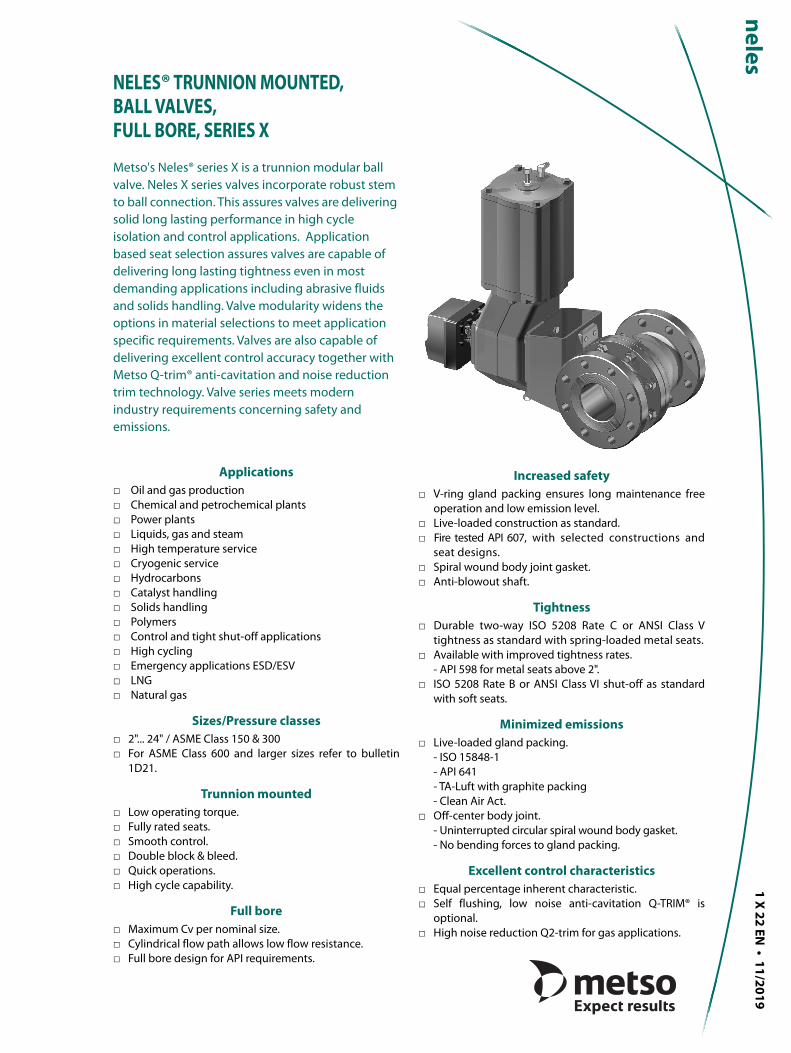
EXPLODED VIEW
PARTS LISTItem Part description Material
1 Body Stainless steel CF8M Carbon steel WCB Chrome Moly C5
2 Body cap Stainless steel CF8M Carbon steel WCB Chrome Moly C5
3 Ball Stainless steel AISI 316 / CF8M Stainless steel 410
5 Shaft Stainless steel 17-4PH / XM-19
7 Ball seat Stainless steel + cobalt based alloy / PTFE or filled PTFE Stainless steel 410 +CrC
8 Bonnet Stainless steel CF8M Carbon steel WCB Chrome Moly C5
9 Gland Stainless steel CF8M
10 Key Stainless steel AISI 329
12 Stud ASTM A 193 gr. B8M ASTM A 320 gr. L7M
13 Stud ASTM A 193 gr. B8M ASTM A 320 gr. L7M
14 Stud ASTM A 193 gr. B8M ASTM A 320 gr. L7M
16 Hexagon nut ASTM A 193 gr. 8M ASTM A 194 gr. 2 HM
17 Hexagon nut ASTM A 193 gr. 8M ASTM A 194 gr. 2 HM
18 Hexagon nut ASTM A 193 gr. 8M ASTM A 194 gr. 2 HM
62 Seat spring Alloy 825
63 Back seal PTFE or graphite
64 Back-up ring PTFE
65 Body gasket Stainless steel AISI 316 + PTFE or graphite filled spiral wound
66 Bonnet gasket PTFE or graphite
69 Packing ring PTFE or graphite
70 Thrust bearing PTFE or cobalt based alloy
71 Thrust bearing Cobalt based alloy
89 Trunnion plate Stainless steel, ASTM A 351 gr. CF8M Stainless steel, ASTM A743 gr. CA15
91 Bearing spacer Cobalt based alloy
99 Trunnion bearing PTFE + Stainless steel
150 Disc spring set Electroless nickel plated spring steel (EN 10083-1.8159)
162
6562
62
63
63
10
12
1
64
64
18
7
89
5
7071
817
69
9
150
9199
7
89
99913
66
14
TECHNICAL BULLETIN 11/19
N E L E S ® T R U N N I O N M O U N T E D , B A L L V A L V E S , F U L L B O R E , S E R I E S X1 x 2 2 E N
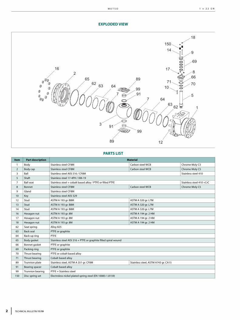
EXPLODED VIEW
PARTS LIST
ITEM PART DESCRIPTIONMaterial
STAINLESS STEEL CARBON STEEL WCB
1 Body Stainless steel CF8M Carbon steel WCB
2 Body cap Stainless steel CF8M Carbon steel WCB
3 Ball Stainless steel AISI 316 / CF8M Stainless steel AISI 316 / CF8M
5 Shaft Stainless steel 17-4PH / XM-19 Stainless steel 17-4PH / XM-19
7 Seat Stainless steel AISI 316 + cobalt based alloy / Stainless steel AISI 316 + CrC / TC2 / PTFE
Stainless steel AISI 316 + cobalt based alloy / Stainless steel AISI 316 + CrC / TC2 / PTFE
8 Bonnet Stainless steel CF8M Carbon steel WCB
9 Gland Stainless steel CF8M Stainless steel CF8M
10 Key Stainless steel AISI 329 / UNS S31803 Stainless steel AISI 329 / UNS S31803
12 Stud ASTM A 193 gr. B8M ASTM A 320 gr. L7M
13 Stud ASTM A 193 gr. B8M ASTM A 320 gr. L7M
14 Stud ASTM A 193 gr. B8M ASTM A 320 gr. L7M
16 Hexagon nut ASTM A 194 gr. 8M ASTM A 194 gr. 7M
17 Hexagon nut ASTM A 194 gr. 8M ASTM A 194 gr. 7M
18 Hexagon nut ASTM A 194 gr. 8M ASTM A 194 gr. 7M
36 Anti-static spring DIN 17224-1.4310 DIN 17224-1.4310
62 Seat spring UNS N06625 UNS N06625
63 Braided seal square Graphite Graphite
65 Body seal Stainless steel AISI 316 + PTFE / graphite Stainless steel AISI 316 + PTFE / graphite
66 Bonnet gasket Graphite / PTFE Graphite / PTFE
69 Packing ring Graphite / PTFE Graphite / PTFE
70 Thrust bearing AISI 316 + PTFE / Coated metal AISI 316 + PTFE / Coated metal
75 Braided seal square Graphite Graphite
89 Trunnion plate Stainless steel CF8M Stainless steel CA15
89A Pin A564 gr. 630 H1150D / ASTM A479 gr. XM-19 A564 gr. 630 H1150D / ASTM A479 gr. XM-19
91 Thrust bearing AISI 316 + PTFE / Coated metal AISI 316 + PTFE / Coated metal
99 Trunnion bearing AISI 316 + PTFE / Coated metal AISI 316 + PTFE / Coated metal
129 Back seal Graphite Graphite
130 Support ring AISI 316 AISI 316
150 Disc spring set AISI 304 AISI 304
162 65 75 62 130 129 63 7
89A 89A89
756213063 1299991
3
99
91
89A89A89 12
13
36
5
10
7066
69
17
14
9150
18
8
7
TECHNICAL BULLETIN 11/19 3

M E T S O
4 TECHNICAL BULLETIN 11/19
1 x 2 2 E N
TECHNICAL SPECIFICATIONProduct type
Full bore trunnion mounted ball valve.Split body design.Flanged.
Pressure ratingsASME Class 150 and 300.
Size range2"... 24" in ASME Class 150 & 300.
Temperature range-50 ... +400 °C / -60 ... +750 °F, consult factory for higher tempera-ture applications.
Design standardValve body ASME B16.34.Valve flanges ASME B16.5.Face-to-face ASME B16.10 long pattern.Actuator mounting ISO 5211.
Standard materialsBody ASTM A216 gr. WCB.
ASTM A351 gr. CF8M.Ball ASTM A351 gr. CF8M/AISI 316 +
hard chrome plating with metal seats.Bearings PTFE or cobalt based alloy.Seats AISI 316+cobalt based alloy.
AISI 316+PTFE insert.Seals/gaskets PTFE, graphite.Body gaskets Spiral wound with PTFE or graphite
filler.
Gland packing PTFE (V-ring) or graphite with liveloaded construction.
Bolting B8M/8M with stainless steel body.L7M/2HM with carbon steel body.
Standard optionsHigh temperature linkages.Oxygen construction for gaseous oxygen service.High temperature design.Carbide or NiBo ball coating.Q-TRIM design (2" ... 24")Q2-TRIM design (2" ... 16")NACE MR-01-03 as standard, NACE MR-01-75 on request.
Material and test certificationEN 10204-3.1 material certificates for body and bonnet.Tightness test certificate.
Fire testedAPI 607, with D, B, K, G and H seats.
Valve testingEach valve is tested for body integrity and seat tightness.The body test pressure is 1.5 x PN. The seat test pressure is 1.1 x PN. Test medium is inhibited water. Air test upon request.
Valve tightnessISO 5208 Rate C or Class V for metal seats.ISO 5208 Rate B or Class VI for soft seats.Other tightness rates upon request.
MAXIMUM ALLOWABLE p IN CONTROL SERVICE MAXIMUM ALLOWABLE p IN ON-OFF SERVICE
Temperature (°C)
Temperature (°F)
p (b
ar)
p (p
si)
38 50 100 150 200 250 300 350 375 400 4500
10
20
30
40
0
100
200
300
400
500
100 122 212 302 392 482 572 662 707 752 842
ASME Class 300
PTFE bearings Metal bearings
ASME Class 150
Temperature (°C)
Temperature (°F)
p (b
ar)
p (p
si)
38 50 100 150 200 250 300 350 375 400 450
0
10
20
30
40
50
60
0
200
400
600
800
100 122 212 302 392 482 572 662 707 752 842
ASME Class 300
PTFE bearings Metal bearings
ASME Class 150
□ PTFE/metal bearings □ Chrome plated ball □ PTFE/metal bearings □ Chrome plated ball
Note: When Carbide or Nickel Boron coatings are used according to given technical limitations, max body material P/Tvalues can be used. Always consider shaft strength, consult factory.

N E L E S ® T R U N N I O N M O U N T E D , B A L L V A L V E S , F U L L B O R E , S E R I E S X1 x 2 2 E N
STANDARD SEAT CONSTRUCTIONS AND MATERIALS
SMetal seat
Ball seat: Stainless steel + hard facing.Seat seal: Viton® GF O-ring.Spring: INCONEL® 625.Temp. range: -30 ... +200 °C / -22 ... +390 °F.
BSolids proof metal seat
Ball seat: Stainless steel + hard facing.Seat seal: Viton® GF O-ring/graphite.Spring: INCONEL® 625.Temp. range: -30 ... +200 °C / -22 ... +390 °F.
Fire safe
KHigh temperature solids proof metal seat
Ball seat: Stainless steel + hard facing.Seat seal: Graphite/graphiteSpring: INCONEL® 625.Temp. range: -50 ... 450 °C / -60 ... +840 °F.Leakage class: upto ISO Rate D / FCI 70.2 Class V
(water)Fire safe
GHigh temperature solids proof metal seat
Ball seat: Stainless steel + hard facing.Seat seal: Graphite/graphiteSpring: INCONEL® 625.Temp. range: -50 ... 425 °C / -60 ... +800 °F.Leakage class: upto FCI 70.2 Class VI
Fire safe
LPolymer proof seat
Ball seat: Stainless steel + hard facing.Seat seal: Viton GF O-ring / Graphite.Temp. range: - 30 ... +200 °C / -22 ... +390 °F.Note: - Sizes 2" - 8"
- Size 10" with single seat design only.
TECHNICAL BULLETIN 11/19 5

M E T S O
6
1 x 2 2 E N
STANDARD SEAT CONSTRUCTIONS AND MATERIALS
ACTUATOR SELECTIONX-series valve can be equipped with the following Metso actuator types:B1C/B1J Pneumatic double acting or spring return actuator.
Actuators available for size range DN 50 - 600 / 2"-24"B1C/B1J actuators have an ISO 5211 mounting face.
M Gear operator for valve sizes DN 50-300 / 2"-12".When selecting other actuators, please contact your local Metso representative.
For the correct actuator selection in on-off service, you need to know the following process data:- valve size and seat type- supply pressure for the actuator- maximum shut-off pressure across the valve.
HBellows seat
Ball seat: Stainless steel + hard facing.Seat seal: Graphite.Temp. range: -50 ... +400 °C / -60 ... +750 °F.Note: For temperature above +400 °C/
+750 °F please consult factory.Not available for XM (Class 150) sizes 2"-6" / DN 50-150Fire safe
TSoft seat
Ball seat: PTFE.Seat body: Stainless steel.Seat seal: Viton GF O-ring.Spring: INCONEL 625.Temp. range: -30 ... +200 °C / -22 ... +390 °F.
DSoft seat, fire safe
Ball seat: PTFE.Seat body: Stainless steel.Seat seal: Viton GF O-ring.Spring: INCONEL 625.Temp. range: -30 ... +200 °C / -22 ... +390 °F.
Fire safe
TECHNICAL BULLETIN 11/19

N E L E S ® T R U N N I O N M O U N T E D , B A L L V A L V E S , F U L L B O R E , S E R I E S X
7
1 x 2 2 E N
TECHNICAL BULLETIN 11/19
DIMENSIONS
ASME 150
Face-to-face dimension acc. to ANSI B16.10, Table 1, long pattern
ASME 300
Face-to-face dimension acc. to ANSI B16.10, Table 1, long pattern
DN ISO FLANGEDIMENSIONS, mm WEIGHT
kg A A1 ØB ØB1 ØD E K □M ØO P
50 F07, F10 178 79 150 146 50.8 203 168 4.76 20 22.16 10
80 F07, F10, F12, F14 203 96.5 190 190 76.2 225 190 4.76 20 22.16 22
100 F10, F12, F14 229 112 230 241 101.6 296 250 6.35 25 27.75 32
150 F14, F16 394 197 280 338 152.4 373 305 9.53 40 44.23 75
200 F14, F16, F25 457 229 343 426 203.2 453 385 9.53 40 44.23 190
250 F14, F16, F25,F30 533 267 407 514 254 562 472 12.7 55 60.6 325
300 F14, F16, F25, F30 610 305 483 592 304.8 605 515 12.7 55 60.6 480
350 F16, F25, F30, F35 686 343 533 665 340 741 607 19.05 75 83.15 635
400 F16, F25, F30, F35 762 381 597 750 390 779 633 22.23 85 94.63 840
450 F30, F35 864 457 635 800 436 793.9 645.7 22.23 85 95.68 1001
500 F30, F35 914 495.5 700 885 487 811 665 22.23 85 95.68 1304
600 F25, F30, F35, F40 1067 571.5 815 1041 589 987 831 22.23 95 105.87 2087
DN ISO FLANGEDIMENSIONS, mm WEIGHT
kgA A1 ØB ØB1 ØD E K □M ØO P
50 F07, F10 216 89 165 146 50.8 203 168 4.76 20 22.16 15
80 F07, F10, F12, F14 282 141 210 200 76.2 225 190 4.76 20 22.16 32
100 F10, F12, F14 305 152 255 254 101.6 296 250 6.35 25 27.75 58
150 F14, F16 403 201 320 353 152.4 373 305 9.53 40 44.23 125
200 F14, F16, F25 502 249 380 462 203.2 453 385 9.53 40 44.23 225
250 F14, F16, F25, F30 568 284 445 580 254.0 562 472 12.70 55 60.60 330
300 F14, F16, F25, F30 648 324 520 652 304.8 605 515 12.70 55 60.60 610
350 F16, F25, F30, F35 762 381 585 700 340.0 741 607 19.05 75 83.15 800
400 F16, F25, F30, F35 838 419 650 799 390.0 779 633 22.23 85 94.63 1015
450 F30, F35 914 389.5 710 825 436 793.9 645.7 22.23 85 95.68 1235
500 F25, F30, F35, F40 991 457 775 906 487 881 725 22.23 95 105.87 1692
600 F35, F40 1143 533.5 915 1060 589 1090 885 31.75 120 136.54 2636
B1
O
E K
M P
B
A
A1
DN D
S
V U W
DN 450 - 600
DN 250 - 400
T
S
U V
C

M E T S O
8
1 x 2 2 E N
TECHNICAL BULLETIN 11/19
ASME 150
Face-to-face dimension acc. to ANSI B16.10, Table 2, long pattern
ASME 300
EN PN 10 - 40
Size ISO FLANGEDIMENSIONS, inch WEIGHT
lbs A A1 ØB ØB1 ØD E K □M ØO P
2 F07, F10 7.01 3.11 5.91 5.75 2.00 7.99 6.61 0.19 0.79 0.87 22
3 F07, F10, F12, F14 7.99 3.80 7.48 7.48 3.00 8.86 7.48 0.19 0.79 0.87 48.4
4 F10, F12, F14 9.02 4.41 9.06 9.49 4.00 11.65 9.84 0.25 0.98 1.09 70.4
6 F14, F16 15.51 7.76 11.02 13.31 6.00 14.69 12.01 0.38 1.57 1.74 165
8 F14, F16, F25 17.99 9.02 13.50 16.77 8.00 17.83 15.16 0.38 1.57 1.74 418
10 F14, F16, F25, F30 20.98 10.51 16.02 20.24 10.00 22.13 18.58 0.50 2.17 2.39 715
12 F14, F16, F25, F30 24.02 12.01 19.02 23.31 12.00 23.82 20.28 0.50 2.17 2.39 1056
14 F16, F25, F30, F35 27.01 13.50 20.98 26.18 13.39 29.17 23.90 0.75 2.95 3.27 1397
16 F16, F25, F30, F35 30.00 15.00 23.50 29.53 15.35 30.67 24.92 0.88 3.35 3.73 1848
18 F30, F35 34.02 17.99 25.00 31.50 17.17 31.26 25.42 0.88 3.35 3.77 2224
20 F30, F35 35.98 19.51 27.56 34.84 19.17 31.93 26.18 0.88 3.35 3.77 2898
24 F25, F30, F35, F40 42.01 22.50 32.09 40.98 23.19 38.86 32.72 0.88 3.74 4.17 4638
Size ISO FLANGEDIMENSIONS, inch WEIGHT
lbsA A1 ØB ØB1 ØD E K □M ØO P
2 F07, F10 8.50 3.50 6.50 5.75 2.0 7.99 6.61 0.19 0.79 0.87 33
3 F07, F10, F12, F14 11.12 5.55 8.25 7.87 3.0 8.86 7.48 0.19 0.79 0.87 70
4 F10, F12, F14 12.00 6.00 10.00 10.00 4.0 11.65 9.84 0.25 0.98 1.09 128
6 F14, F16 15.88 7.93 12.50 13.90 6.0 14.69 12.01 0.38 1.57 1.74 276
8 F14, F16, F25 19.75 9.80 15.00 18.19 8.0 17.83 15.16 0.38 1.57 1.74 496
10 F14, F16, F25, F30 22.38 11.18 17.50 22.83 10.0 22.13 18.58 0.50 2.17 2.39 727
12 F14, F16, F25, F30 25.50 12.76 20.50 25.67 12.0 23.82 20.28 0.50 2.17 2.39 1345
14 F16, F25, F30, F35 30.00 15.00 23.00 27.56 13.4 29.17 23.90 0.75 2.95 3.27 1764
16 F16, F25, F30, F35 33.00 16.50 25.50 31.46 15.4 30.67 24.92 0.88 3.35 3.73 2237
18 F30, F35 35.98 15.33 27.95 32.48 17.17 31.26 25.42 0.88 3.35 3.77 2744
20 F25, F30, F35, F40 39.02 17.99 30.51 35.67 19.17 34.69 28.54 0.88 3.74 4.17 3760
24 F35, F40 45.00 21.00 36.02 41.73 23.19 42.91 34.84 1.25 4.72 5.38 5858
Type DNDIMENSIONS, mm WEIGHT
kgØD A A1 ØB ØB1 E K M N ØO P S T U V W C
PN10
450 436 864 432 615 800 794 648 22.23 146 85 94.63 330 21.3 M30 M20 M20 M27 981
500 487 914 457 670 885 811.5 665.5 22.23 146 85 94.63 330 21.3 M30 M20 M20 M27 1288
600 589 1067 533.5 780 1041 987 831 22.23 156 95 105.87 400 23.6 M30 M30 M24 M30 2037
PN16
450 436 864 432 640 800 794 648 22.23 146 85 94.63 330 21.3 M30 M20 M20 M27 1011
500 487 914 457 715 885 811.5 665.5 22.23 146 85 94.63 330 21.3 M30 M20 M20 M27 1328
600 589 1067 533.5 840 1041 987 831 22.23 156 95 105.87 400 23.6 M30 M30 M24 M30 2141
PN25
450 436 914 457 710 785 794 648 22.23 146 85 94.63 330 21.3 M30 M20 M20 M36 1249
500 487 991 495.5 775 880 881 725 22.23 156 95 105.87 400 23.6 M30 M30 M24 M39 1692
600 589 1143 571.5 915 1050 1090 885 31.75 205 120 136.54 460 23.6 M30 M30 M24 M39 2636
PN40
450 436 914 457 710 825 794 648 22.23 146 85 94.63 330 21.3 M30 M20 M20 M36 1249
500 487 991 495.5 775 906 881 725 22.23 156 95 105.87 400 23.6 M30 M30 M24 M39 1692
600 589 1143 571.5 915 1060 1090 885 31.75 205 120 136.54 460 23.6 M30 M30 M24 M39 2636
N E L E S ® T R U N N I O N M O U N T E D , B A L L V A L V E S , F U L L B O R E , S E R I E S X1 x 2 2 E N
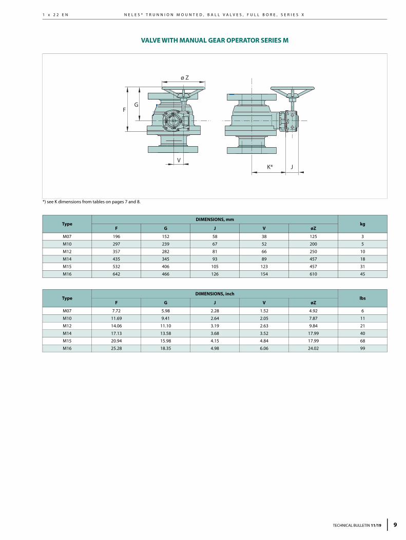
VALVE WITH MANUAL GEAR OPERATOR SERIES M
*) see K dimensions from tables on pages 7 and 8.
TypeDIMENSIONS, mm
kgF G J V øZ
M07 196 152 58 38 125 3
M10 297 239 67 52 200 5
M12 357 282 81 66 250 10
M14 435 345 93 89 457 18
M15 532 406 105 123 457 31
M16 642 466 126 154 610 45
TypeDIMENSIONS, inch
lbsF G J V øZ
M07 7.72 5.98 2.28 1.52 4.92 6
M10 11.69 9.41 2.64 2.05 7.87 11
M12 14.06 11.10 3.19 2.63 9.84 21
M14 17.13 13.58 3.68 3.52 17.99 40
M15 20.94 15.98 4.15 4.84 17.99 68
M16 25.28 18.35 4.98 6.06 24.02 99
K* JV
GF
ø Z
TECHNICAL BULLETIN 11/19 9

M E T S O
1
1 x 2 2 E N
TOPWORK ASSEMBLY DIMENSIONS
*) See K and ØB1 dimensions from tables on page 7 and 8.
B1C ACTUATOR
B1J/B1JA ACTUATOR
VALVE + B1C/B1J/B1JA
K* J
X
GF
NPT
V
NPT
ØB1*
ActuatorDIMENSIONS, mm
NPT kgF G J V X
B1C6 400 260 283 36 90 1/4 4.2
B1C9 455 315 279 43 110 1/4 9.6
B1C11 540 375 290 51 135 3/8 16
B1C13 635 445 316 65 175 3/8 31
B1C17 770 545 351 78 215 1/2 54
B1C20 840 575 385 97 215 1/2 73
B1C25 1040 710 448 121 265 1/2 131
B1C32 1330 910 525 153 395 3/4 256
B1C40 1660 1150 595 194 505 3/4 446
B1C50 1970 1350 690 242 610 1 830
ActuatorDIMENSIONS, inch
NPT lbsF G J V X
B1C6 15.75 10.24 11.14 1.42 3.54 1/4 9
B1C9 17.91 12.40 10.98 1.69 4.33 1/4 21
B1C11 21.26 14.76 11.42 2.01 5.31 3/8 35
B1C13 25.00 17.52 12.44 2.56 6.89 3/8 68
B1C17 30.31 21.46 13.82 3.07 8.46 1/2 119
B1C20 33.07 22.64 15.16 3.82 8.46 1/2 161
B1C25 40.94 27.95 17.64 4.76 10.43 1/2 289
B1C32 52.36 35.83 20.67 6.02 15.55 3/4 564
B1C40 65.35 45.28 23.43 7.64 19.88 3/4 983
B1C50 77.56 53.15 27.17 9.53 24.02 1 1829
ActuatorDIMENSIONS, mm
NPT kgF G J V X
B1J/B1JA6 485 368 273 36 110 3/8 8
B1J/B1JA8 560 420 279 43 135 3/8 17
B1J/B1JA10 650 490 290 51 175 3/8 30
B1J/B1JA12 800 620 316 65 215 1/2 57
B1J/B1JA16 990 760 351 78 265 1/2 100
B1J/B1JA20 1200 935 358 97 395 3/4 175
B1J/B1JA25 1530 1200 448 121 505 3/4 350
B1J/B1JA32 1830 1410 525 153 540 1 671
B1J/B1JA40 2095 1578 580 194 724 1 1100
ActuatorDIMENSIONS, inch
NPT lbsF G J V X
B1J/B1JA6 19.09 14,49 10.75 1.42 4.33 3/8 20
B1J/B1JA8 22.05 16.54 10.98 1.69 5.31 3/8 37
B1J/B1JA10 25.59 19.29 11.42 2.01 6.89 3/8 66
B1J/B1JA12 31.50 24.41 12.44 2.56 8.46 1/2 126
B1J/B1JA16 38.98 29.92 13.82 3.07 10.43 1/2 220
B1J/B1JA20 47.24 36.81 14.09 3.82 15.55 3/4 386
B1J/B1JA25 60.24 47.24 17.64 4.76 19.88 3/4 771
B1J/B1JA32 72.05 55.51 20.67 6.02 21.26 1 1479
B1J/B1JA40 82.48 62.13 22.8 7.64 28.5 1 2424
0 TECHNICAL BULLETIN 11/19

N E L E S ® T R U N N I O N M O U N T E D , B A L L V A L V E S , F U L L B O R E , S E R I E S X1 x 2 2 E N
HOW TO ORDER
NOTE ! Balls with coating (/) are normally used in metal seated valves.
* Bolting materials for stainless steel body** Bolting materials for carbon and low alloy steel body
1. 2. 3. 4. 5. 6. 7. 8. 9. 10. 11. XG 06 D W TA S6 PJ S A B E
1. sign VALVE SERIES & STYLE & FACE-TO-FACEXM Full bore, trunnions, f-to-f ANSI B 16.10, Table 1, long pattern, ASME 150.
XG Full bore, trunnions, f-to-f ANSI B 16.10, Table 2, long pattern, ASME 300.
2. sign SIZEASME VALVES EN VALVES
2. sign NPS 2. sign DN02 2” 050 50
03 3” 080 80
04 4” 100 100
06 6” 150 150
08 8” 200 200
10 10” 250 250
12 12” 300 300
14 14” 350 350
16 16” 400 400
18 18” 450 450
20 20” 500 500
24 24” 600 600
3. sign PRESSURE CLASSC ASME Class 150
D ASME Class 300
J PN 10
K PN 16
L PN 25
M PN 40
4. sign END CONNECTION STYLE
W Raised face, ASME B 16.5, (Ra 3.2 - 6.3/RMS 125 - 250) standard with ASME flanges.
C EN 1092 -1 Type B1, raised face, standard with EN flanges.
5. sign CONSTRUCTION & APPLICATIONTA Standard construction. Live loaded packing.
TE Single seated. Otherwise standard.
TQ Q-Trim construction. Otherwise standard
EQ Single seated, Q-Trim construction.
2G Q2-trim for gas application, single seated construction, otherwise standard construction
TZ
BAM tested non-metallic parts, for oxygen service. Double seated. Metal bearings; cobalt based alloy. Live loaded graphite packing. Temperature range -50...+200 °C. Max pressure per body rating. Oxygen cleaning acc. to Metso internal procedure.
6. sign BODY MATERIALJ2 ASTM A216 gr WCB
S6 ASTM A351 gr CF8M
J5 ASTM A217 gr C5
7. sign BALL / COATING & STEM MATERIALPJ 316SS / Hard Chrome & 17-4PH
PP 316SS & 17-4PH
PV 316SS/Tungsten carbide, TC2
PX 316SS / Chrome carbide, CrC & 17-4PH
PR 316SS / WC-CO & 17-4PH
PL 316SS / NiBo & 17-4PH
8. signSEAT TYPES AND BACK SEAL/SPRING MATERIALS
Seat type Back seal type Spring Back-up ring
S S, metal, general service O-ring Inconel 625 PTFE
L L, metal,Polymer proof
Graphite / O-ring ---- PTFE
B B, metal, solid proof Graphite/O-ring Inconel 625 PTFE
K K, metal, solid proof Graphite/graphite Inconel 625 ----
G G, metal, solid proof Graphite/graphite Inconel 625 ----
H H, metal, bellows Graphite ---- ----
T T, soft, general service O-ring Inconel 625 PTFE
D D, soft fire safe service
Graphite /O-ring Inconel 625 PTFE
9. sign SEAT AND COATING MATERIAL Seat material Coating
AType 316 stainless steel with S, B and K type seatsAVESTA 248SV with H type seat.
Cobalt based hard facing
BType 316 stainless steel with S, B and K type seatsAVESTA 248SV with H type seat.
Chrome Carbide, CrC-LF
VType 316 stainless steel with S, B, K and L type seatsAVESTA 248SV with H type seat.
Tungsten Carbide,TC2
RType 316 stainless steel with S, B, K and L type seatsAVESTA 248SV with H type seat.
Tungsten Carbide,WC-CO
F F6NM with H-type seat for high temperature NACE service.
Chrome Carbide,CrC-LF
Seat material Insert
T Type 316 stainless steel. PTFE
M Type 316 stainless steel. Filled PTFE
N Type 316 stainless steel. Polyamid
10. signBEARING AND SEAL MATERIALS
Trunnion bearing
PackingsBody
gasketsO-rings
Thrust bearing
A Reinforced PTFE V-rings PTFE PTFE Viton GF Reinforced
PTFE / Metal
B Reinforced PTFE Graphite Graphite Viton GF Reinforced
PTFE / Metal
C Metal V-rings PTFE PTFE Viton GF Metal
D Metal Graphite Graphite Viton GF Metal
H Reinforced PTFE V-rings PTFE PTFE EPDM Reinforced
PTFE / Metal
S Reinforced PTFE Graphite Graphite EPDM Reinforced
PTFE / Metal
U SS + WC-CO Graphite Graphite Viton GF Metal
V SS + WC-CO Graphite Graphite Viton GF Metal
T SS + WC-CO Braided PTFE Graphite Viton GF Metal
11. singBOLTING MATERIALS
Pressure retaining Packing gland bolting Studs Nuts Studs Nuts
Standard for sizes DN 50 - 400/NPS 2 - 16
E* B8M 8M gr. 660 gr. 660
T** L7M 2HM B7 2H
Standard for sizes DN 450 - 600/NPS 18- 24
D * B8M 8M B8M 8M
F ** L7M 2HM L7M 2HM
TECHNICAL BULLETIN 11/19 11

Subject to change without prior notice. Product names in thisbulletin are all trademarks of Metso Flow Control Inc.
Metso Corporation Töölönlahdenkatu 2, PO Box 1220, 00100 Helsinki, FinlandTel. +358 20 484 100http://contact.metso.com/
Metso Flow Control Inc.Vanha Porvoontie 229, P.O. Box 304, FI-01301 Vantaa, Finland.Tel. +358 20 483 150. Fax +358 20 483 151
www.metso.com/valves