Embed Size (px)
Citation preview

Standard MachineShop Guards
First Choice Solutions for Machine Shop Guards
www.machinesafety.co.uk
®

®
Machine guarding systems
Slide & Swing Asidemilling machine guards
Just Swing Asidemilling machine guards
Lathe Guardsthe major & minor range of sliding lathe guards
Lathe GuardsTXS saddle mount lathe shields
Lathe GuardsLXS lathe chuck guards
Lathe GuardsCLG chuck guards
Lathe GuardsTPS steel chuck guards
Drill GuardsDXS safetispeed drill guards
Chip Guardmagnetic based safety chip guard for minimum interference
Grinding Wheel Guardsgrinding wheel guard for minimum interference
1
contents2
6
8
10
11
13
14
15
19
20

2
Slide & Swing Asidemilling machine guards
The patented Slide & Swing Aside Milling Machine Guard has been designed to meetthe stringent guidelines laid down by both legal requirements and industrial necessity. Itis manufactured using impact resistant clear polycarbonate and gives good visibility,immediate access and maximum operator protection. Its unique design ensures that theguard does not impair the performance or the versatility of the machine.
This is the first guard of its kind which enables either small workpieces or large castingsfitting and overhanging the milling machine table to be completely protected but at thesame time giving immediate and complete access to the piecepart or casting beingmachined. Each of the front panels can slide to the right or left and swing aside on theirown axis out of the way, finishing in a position parallel to the end panels.
The advantage of the Slide and Swing Aside movement is that you can obtainimmediate access to the whole length of the table for loading and unloading largeworkpieces, and although the panels slide aside they will not take up any more roomthan the actual length of the table.
Where large castings are being machined that overhang the table, you can slide theguard forward and lock into the position required. This may however leave a gap on theunderside of the guard between the table and front panels. To overcome this situationan Infill Guard can be fitted which also keeps the operator and machine clear fromswarf and coolant.
®
Machine guarding systems
featuresAll round visibility
Unrestricted front access
Ease of installation
Optional sliding accessdoor for applications
requiring access to quill
Suitable for:-
Horizontal,Vertical,Universal & Turret
machines

3
®
Machine guarding systems
The guard is supplied in two separate assemblies which aremounted at each end of the table. A plate fitted with arectangular locating block having equivalent width to the tableslots is positioned at each end of the table in one of the “T”slots and the parrallel sole bars are clamped to the mountingplate by two socket cap screws (allen key supplied). The twoparallel sole bars support a kingpost to which a pivotingbracket is fitted supporting a ball bearing sliding track towhich the polycarbonate transparent front panels are fixed.
the guard
mounting the guard
Each front panel slides aside givingaccess to the table and cutter.
Front panels swing aside parallelto the side panels, giving
maximum access to the table.
Spring loadedlocking catch
Parallel Sole bars, shownwith side windows removedfor clarity of fixing details
*If this section of "T" slot is less than 60mmlong, use 2J mounting kit (shown on nextpage). *The guard can slide backwardsand forwards along the sole bars.
Retainingwasher
Socket cap screw
Washer
Table clamp
Locating block Table locators‘T’ nut
Stud
Nut
For mounting in ‘T’ slots

4
®
Machine guarding systems
W
H
L
dimensions
mounting the guard
how to order
Select size of guard from the table opposite by tablesize. Specify type of mounting and 'T' slot size as fig:1.
A risk assessment could necessitate the use ofElectrical Interlocks, Back Guards & Infill Guards,details of which are shown on the next page.
Our sales engineers are always available to assist inspecifying the correct guard.
htgneL elbaT xaMhtgneL elbaT niMnoitpircseDepyT drauGSSA/00H RHS Sliding Door & LHS Formed Panel 610 914SSA/1H RHS Sliding Door & LHS Hinged Panel 914 1118
6801018srooD gnidilS 2H7/ASS28217801srooD gnidilS 2H6/ASS68413821srooD gnidilS 2H2/ASS88617841srooD gnidilS 2XEH2/ASS49919861srooD gnidilS 2H3/ASS69125991srooD gnidilS 2XEH3/ASS
Special GuardsVersions of the SSA can be manufactured to suit certainspecialised machines and equipment with the options ofvarious heights, widths and lengths.
Retainingwasher Retaining
washer
Locating blockFixed ‘T’ slot locator
‘T’ nut
Tableclamp
WasherNut
Washer
Socket capscrew
Washer
Locating block
Table
Table clamp2 x M6 fixings:not supplied
Retainingwasher
Stud
Socket capscrewSocket cap screw
Washer
Table clamp
Locating block Table locators‘T’ nut
Stud
Nut
To be used where ‘T’ slots cannot beinterrupted
Designed for Bridgeport 21 series and similarmachines. Also for use where extension ‘T’slots are less than 60mm long
For mounting in ‘T’ slots
gnitnuoM dnE elbaTgnitnuoM J2gnitnuoM dradnatS
End elevation showing side guardsFront view with sliding guards closed
PLEASE SPECIFY TEESLOT SIZE

5
1 Back GuardFor guarding the rear of the table at either side of the headstock.Thetwo clear panels are both located on a single slide runner assemblywhich is fixed to the ends of the parallel sole bars. Top support isprovided by dual rollers. As the table moves from side to side thetwo linked panels are free to slide in their mountings thus providingcomplete rear protection at all times with no hindrance to tablemovement.The standard back guard is suitable for tables up to1600mm. For larger tables a telescopic or custom backguard isavailable.
2 Electrical InterlockAdditional operator safety can be provided by the installation of thiscompact yet totally effective and reliable safety switch. As the twofront panels are closed the actuator tongue enters the switch bodyand closes internal contacts linked to the machine controls thusallowing machine operation only when the guard is properly closed.Interlocks are normally fitted to the right hand side on SSA/2/3/6 andto the left hand side on SSA/00/1.
3 Coolant Drip Trays (Infill guard)To protect operators from coolant drip and overspill of swarf from thefront of the table and also prevent access underneath the frontpanel. Particularly relevant when machining large irregular castingswhich overhang the machine bed.Two types are available, one hasan adjustable tray width to cater for different overhangs.The othertype is a fixed width tray with a lip on three sides to which can beattached an optional brush strip to seal the small gap between thetray and the bottom edge of the front guard panels. Both typeslocate to the sole bars. Specials are available upon request.
4 Sliding Access DoorA portion of the front panel can be converted to a sliding accessdoor allowing access to the machines operating levers, e.g.Bridgeport Mill for quill feed arm access.The access panel can bepositioned on either the right or left panel.The use of two slidingaccess doors, one on each panel can also be supplied.This option isstandard on the SSA7 but is also available on other guards ifrequired.
®
Machine guarding systems
additional guard items
LHS
Electrical InterlockGuardmaster Trojan 5
Coolant Drip Tray/Infill Guard
Flush fittingtray allowstools etc, to sitflush tothemachine table
Sliding Access Door
Fixed tray overlap fitting.Length = Table Length. Pleasestate width when ordering
Brush stripincluded
Fixed tray flush fitting. Length = Table Length.Please state width when ordering
Option of left hand orright hand side fixing of
switch. The Safety Switch issupplied fitted to the right hand side
as shown unless otherwise stated
RHS

6
Just Swing Asidemilling machine guards
The JSA-1E Interlocked Vertical Milling Machine Guard is suitable for Bridgeport Series1 vertical milling machines or similar.
Its operator friendly proximity guard provides operator protection without the usualconstraints of a full table guard. When not required it simply swings aside allowing fulloperator access to the machine table for setting and measurement, etc.
Not only is it suitable for tool room machines but also R & D workshops, prototype workand small batch production machines. It has a three sided framed polycarbonate screenwith support arm and mounting bracket with an optional right hand side cut-out foraccess to quill feed arms (common to Bridgeport machines). Adjustment is easilyattainable in both Z and Y axis.
The guard can be fitted to either the left or right hand side of the machine, the standardbeing on the left.
®
Machine guarding systems
featuresOperator friendlyproximity guard
Unrestricted front access
Ease of adjustment
Suitable for:Tool room machines, R & D
workshops, small batchproduction machines

7
®
Machine guarding systems
the guard
Option: Can be supplied as opposite hand version
670-850 max

8
Lathe Guardsthe major and minor range of sliding lathe guards
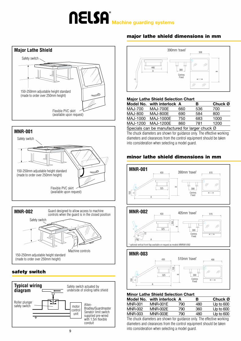
The Major Sliding Lathe shieldsThese high quality steel lathe shields with a polycarbonate window provide maximumoperator protection on standard machines or large C.N.C. lathe applications. Suitablefor chucks up to 1200mm (larger sizes are available from our specials department).Thefour support stands are adjustable for ease of mounting to the headstock.The shieldslides over the headstock and out of the way when it is necessary to work at the pointof operation for changing tooling, piecepart, etc. The shield can be supplied with anelectrical interlock incorporating a safety limit switch working in accordance with EN1088, which will prevent the machine from running when the guard is in the openposition.
The Minor Sliding Lathe shieldsThese guards are manufactured from steel and feature 2 windows of clearpolycarbonate. Being situated on top and front panels, these windows provide goodvisibility for the operator. The shield slides over the headstock allowing access to thepoint of operation.This Lathe Shield is designed to guard chucks up to 600mmdiameter. (Refer to the Major range for larger chucks).The shield can be supplied with anelectrical interlock incorporating a safety limit switch working in accordance with EN1088, which will prevent the machine from running when the guard is in the openposition. The guards are easily fitted and can be adapted to fit almost any machine.
®
Machine guarding systems
featuresUnique construction allows
excellent visibility
A range of sizes to suitchucks up to 1200mm
Ease of installation
9
®
Machine guarding systems
major lathe shield dimensions in mm
safety switch
Safety switch
Safety switch
Safety switch
Guard designed to allow access to machinecontrols when the guard is in the closed position
Major Lathe Shield
MNR-001
MNR-002
Typical wiringdiagram
150-250mm adjustable height standard(made to order over 250mm height)
390mm ‘travel’
390mm ‘travel’
405mm ‘travel’
510mm ‘travel’
MNR-001
MNR-002
MNR-003
CentresFixed
300
150-250mm adjustable height standard(made to order over 250mm height)
150-250mm adjustable height standard(made to order over 250mm height)
Machine controls
Safety switch actuated byunderside of sliding lathe shield
Roller plungersafety switch Allen-
Bradley/GuardmasterSenator limit switchsupplied pre-wiredwith 1.5m flexibleconduit
motorcontrol
unit
Flexible PVC skirt(available upon request)
Flexible PVC skirt(available upon request)
448
500
BA
CentresFixed
CentresFixed
CentresFixed
Major Lathe Shield Selection ChartModel No. with interlock A B Chuck ØMAJ-700 MAJ-700E 660 536 700MAJ-800 MAJ-800E 690 584 800MAJ-1000 MAJ-1000E 750 683 1000MAJ-1200 MAJ-1200E 860 781 1200Specials can be manufactured for larger chuck ØThe chuck diameters are shown for guidance only. The effective workingdiameters and clearances from the control equipment should be takeninto consideration when selecting a model guard.
Minor Lathe Shield Selection ChartModel No. with interlock A B Chuck ØMNR-001 MNR-001E 790 480 Up to 600MNR-002 MNR-002E 790 360 Up to 600MNR-003 MNR-003E 790 480 Up to 600The chuck diameters are shown for guidance only. The effective workingdiameters and clearances from the control equipment should be takeninto consideration when selecting a model guard.
minor lathe shield dimensions in mm
300
300
300
615
515
400
430
430
430
240
150
150
150
150
325
325
325
22
BB
B
A
A
A
*
* optional vertical front flap available on request as models MNR001/002

10
Lathe GuardsTXS saddle mount lathe shields
This protection shield is normally mounted on the cross-slide of the lathe althoughmounting to other parts of the machine is possible. The steel structure with a 4mm thickpolycarbonate window allows protection from chips and coolant, along with visibility tothe point of operation.The front portion of the shield hinges up for access.The shield isideal for applications where a simple chuck guard is insufficient, as it protects theoperator when machining is taking place at a distance from the headstock.
®
Machine guarding systems
featuresEase of installation
Light but very strongand easy to use
Good visibility inworking conditions
Protects when machiningaway from the headstock
TXS - Dimensions in mmHinges upfor access
Adjustablemount to saddle
TSX-
100
TSX-
200
220
285
550
220
20
E
D
F
Bhinge C
A
TXS-100 & TXS-200 - Dimensions in mmPart No. TXS-100 TXS-200
075514A503002B052002C563513D001001E053003F

11
Lathe Guardsthe LXS lathe chuck guards
The LXS Lathe Chuck Guard consists of a semicircular construction made from highimpact resistant transparent material which is mounted on to a chromium platedextension tube, fastened to the headstock of the lathe.
The semicircular guard covers the upper half of the lathe chuck as shown above.
Access to the workpiece is quick and easy, the guard is lifted and swung away from theoperator.
The size of the guard required is dependant on the centre height of the lathe and thediameter of the chuck. On lathes up to a centre height of 7" there is only a smallvariation in diameter between the 3 and 4 jaw chucks, and therefore one size of guardwill suffice. On lathes in excess of a centre height of 7" there is a greater variation in thediameter between the chucks. It is therefore advisable to use two guards to giveadequate protection, eg. LXS 653 shown on opposite page with LXS 400 and LXS 600.
The chromium plated extension tube to which the guard isfastened is mounted to the headstock of the lathe by means ofa universal mounting bracket incorporating an electrical safetyinterlock. The interlock incorporates cam operation, is sealedto IP 66 and conforms to EN 1088 and EN 60947-5-1. All unitsare provided with PVC covered flexible steel conduit and awiring diagram.
®
Machine guarding systems
featuresHigh impact resistant
clear PVC
An efficient Lathe Guardwhich gives maximum
operator protectionwith good visibility, fast
& easy access tothe workpiece
Choice of mounting brackets
Electrical Interlocks
mounting bracket with safety interlock

12
®
Machine guarding systems
ordering instructions
universal mountingbracket dimensions
mounting locations, Note: no safety interlock
Face mountedGuard mounted to the face of the headstock withuniversal mounting bracket incorporatingRotacam safety interlock switch.
Recess top mountedGuard mounted in the top recess of theheadstock with universal mounting bracketincorporating Rotacam safety interlock switch.
Back mountedGuard mounted to the back of the headstockwith universal mounting bracket incorporatingRotacam safety interlock switch.
Select the guard required from the selection chart. If you have selected a guard with an electrical interlock, no further information is required. Forguards without interlocks you need to specify the type of mounting bracket required from the above table. If no mounting bracket is specified then atype ‘B’ bracket will be supplied.
Important: In the best interests of safety we recommends the use of safety interlocks where practically possible.
C
H E
F
D G
B inside dia
A max
dia
Mounting locations using universal mounting bracket with dafety interlock
10050
50100
25
10 96105
8325
2555
15
80
15 45 48 68
Front View
Top View
2 partbracket
Bush
Front bracketbolts to rearbracket
Mounting holes
Rear bracket bolts to headstock
End View
25 Bore
Chamfer2 at 45o
2 Holes8 Dia
31 40 Dia
4012
Holes7 Dia
25 Bore189
956012
3324
10
72 5038
5076
59CTS77
= =
==
=
===
Type A Model No. LXS 650
Bracket type A is used whenmounting to the top or sideof the headstock
Bracket type B is usedwhen mounting to theface of the headstock
Bracket type B2 is used whereguards with different diametersmay be used to accommodate 3& 4 jaw chucks and is mountedto the face of the headstock
Type B Model No. LXS 652 Type B2 Model No. LXS 653
Mounti
ng l
ocati
ons
Fix
ing b
rackets
Com
ments
Model A B C D E F G HLXS-200 140 200 128 25 165 60 250 35LXS-200E 140 200 128 25 165 75 310 35LXS-300 240 300 178 25 165 60 250 35LXS-300E 240 300 178 25 165 75 310 35LXS-400 340 400 228 25 203 60 290 35LXS-400E 340 400 228 25 203 75 310 35LXS-500 440 500 278 25 203 60 290 35LXS-500E 440 500 278 25 203 75 310 35LXS-600 540 600 328 25 203 60 290 35LXS-600E 540 600 328 25 203 75 310 35Model No.s with the letter ‘E’ at the end represent model with interlock
**
* special fabricated LXS screen
13
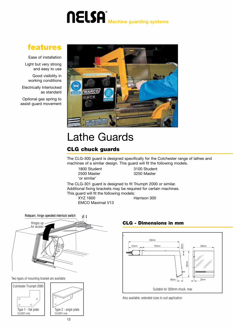
Lathe GuardsCLG chuck guards
The CLG-300 guard is designed specifically for the Colchester range of lathes andmachines of a similar design. This guard will fit the following models.
1800 Student 3100 Student2500 Master 3250 Master‘or similar’
The CLG-301 guard is designed to fit Triumph 2000 or similar.Additional fixing brackets may be required for certain machines.This guard will fit the following models: XYZ 1600 Harrison 300 EMCO Maximat V13
®
Machine guarding systems
featuresEase of installation
Light but very strongand easy to use
Good visibility inworking conditions
Electrically Interlockedas standard
Optional gas spring toassist guard movement
CLG - Dimensions in mm
Rotacam, hinge operated interlock switchRotacam, hinge operated interlock switch
Two types of mounting bracket are available
Hinges upfor access
Type 1 - flat plate Type 2 - angle plateCLG301 only CLG301 only
Suitable for 350mm chuck, max
Also available, extended sizes to suit application
560mm
435mm mm003mm521
30mm86mm
285m
m
86m
m
Colchester Triumph 2000

14
Lathe GuardsTPS steel chuck guards
Nelsa's fabricated steel, double hinged chuck guards are for use on machines with upto 1000mm diameter chucks.These guards come complete with mounting pin, plate andsupport bar which are both mounted on the face of the headstock.The hinged frontpanel gives easy access to the chuck.
®
Machine guarding systems
featuresEase of installation
Light but very strongand easy to use
Good visibility inworking conditions
Electrically Interlockedas standard
*
*
Bolts to headstock
*NB. Supplied without fixing holes
Support bar fixedto headstock
Hinges upfor access
Dimensions in mm
Hinge
B
A
TPS - Dimensions in mmModel No. A BTPS-600 350 600TPS-800 350 800TPS-1000 350 1000TPS-1200 350 1200

15
Drill GuardsDXS safetispeed drill guards
The Guard has been specially developed to give maximum all round protection for theoperator with a high standard of visibility without adversely affecting operation time.
The drill guard consists of two major components.The drill guard mounting which isfitted to the quill of the machine and the drill guard sleeves which clip into the mountingand are held in position by three spring loaded ball catches and retaining screws.
The guard consists of two or three sleeves, the inner sleeve being a ribbed cage whichis held stationary in the guard holder. The outer sleeve is free to move up and down onthe inner cage and is fitted with a guide groove which gives radial movement to theouter sleeve thus preventing jamming.
The outer sleeve is fitted with a transparent acrylic window (as standard) held in positionby two slideways and a retaining screw. The window can be quickly removed andreplaced at regular intervals giving maximum visibility at all times. The outer sleeve restson the piecepart or jig. As the drilling operation takes place the inner cage moves downand automatically protects the window from metal slivers which are cut up by the edgesof the inner cage.
The basic drill guard (i.e. DXS-500) is bored suitable for a quill diameter of 2.75"(70mm). The 13 sizes of reducing bushes will cover any quill diameter down to aminimum of 1.5". Determine your quill diameter or point of fixing at the time of orderingand select the appropriate drill guard. If a bush is required, refer to the table opposite.The bush may be ordered separately. Sizes outside the standard range can be suppliedby our 'Specials' department.
®
Machine guarding systems
featuresGives complete
operator protection andclear vision of the job
Smooth telescopic action
Patented spiral guidegroove gives radial
movement to preventjamming by swarf
Unique sprung ballcatch allows quick and
easy access to thechuck, after slackening
the retaining screws
IMPORTANT
Bushes are only used withthe ‘Type A’ mounting toreduce the bore size from70mm down to 37.85mm(shown opposite).
For quill diameters from70mm up to 95mm theType 1L, 2L and 3Lmountings should be used.
NOTE: NO BUSHESREQUIRED.
For other types ofmountings ‘Type AS1, B,1F and 2F’ should be used.

16
®
Machine guarding systems
choosing a Safetispeed drill guard
gnitnuom ’A‘ epyt dradnats rof sehsub gnicuderepyt gnitnuom
All Safetispeeds shown below have a Standard Type A mounting. Other mounting types are available and are shown onthe following page. Reducing bushes are suitable for all drill guards shown on this page.
Choose which type ofSafetispeed you require fromthe above information thenchoose appropriate fixingcollar for your machine.
The 'standard mountingtype A (70mm)' can bebushed to accommodatesmaller diameters. Refer tothe table below.
For all round visibility. Ideal forapplications with limited verticalmovement. MODEL DXS-525
Measurementstaken from theunderside ofthe mounting
101.
6mm
(Max
)
127m
m (M
ax)
63.5
mm
(Min
)
76.2
mm
(Min
)
ModelDXS-530
ModelDXS-520
For all round visibility with adjustableheight fixing. Two sizes available
Measurements taken from theunderside of the mounting
Locking themounting to the sleeve
Measurements takenfrom the undersideof the mounting
Measurements takenfrom the undersideof the mounting
A Guard mounting (clamp)B Guard bodyC Radial telescopic actionD Acrylic window
Standard 2 3/4” (70mm) Bore drill guard mounting for use oncircular non-rotating Quills of any diameter between 1.5” & 23/4” by the use of 13 standard adaptor brushes (right). Quillsof smaller diameter can be fitted with a special bush, made toorder. A mounting of this type is available for circular Quills68mm diameter.
Shown with two stage SafetispeedMODEL DXS-500
Standard type A 2 1/16”
4”
2 3/4” Bore
1 19
/32”
9/16
”
A
B
C
D26
5mm
(Max
)
115m
m (M
ax)
MODEL DXS-500
MODEL DXS-510
M5 socketset
retainingscrew
Fixed clear acrylic Safetispeed
Adj. clear acrylic Safetispeed
Two stage Safetispeed Three stage Safetispeed
Orde
r to
lengt
h
170m
m (M
ax)
95m
m (M
ax)
hsub draug llirDretemaid lliuQinches metric (mm) Model No.2.750 to 2.690 69.85 to 68.33 No brush needed2.638 to 2.580 67.00 to 65.35 DXS-0102.579 to 2.516 65.52 to 63.91 DXS-0152.515 to 2.453 63.90 to 62.31 DXS-0202.452 to 2.393 62.30 to 60.78 DXS-0252.392 to 2.330 60.77 to 59.18 DXS-0302.329 to 2.268 59.17 to 57.61 DXS-0352.267 to 2.201 57.60 to 55.90 DXS-0402.200 to 2.135 55.89 to 54.23 DXS-0452.134 to 2.076 54.22 to 52.73 DXS-0502.075 to 2.020 52.72 to 51.31 DXS-0552.019 to 1.960 51.28 to 49.78 DXS-0601.950 to 1.890 49.53 to 48.00 DXS-0651.550 to 1.490 39.37 to 37.85 DXS-070

17
®
Machine guarding systems
mounting types - continued
three lug mounting
ø
Three Lug Guard Mounting:- This type of mounting willaccommodate quills ranging in general diameter from 23/4" to 3 3/4" (70mm to 95mm). For quill sizes exceeding95mm a special adaptor can be supplied by our specialsdepartment.This design of mounting as illustrated has beendeveloped to fit irregular shaped non-rotating quills. Themountings can be fitted to 'pear shaped' quills havingprojecting bosses which carry the depth adjusting screwand dependent on the angular position of the projection inplan view in relation to the front of the machine theappropriate type can be selected.
Flange Type Mounting:- This mounting has been developed for direct mountingto the non-rotating quill face when clearance holes for M5 screws can be drilledthrough the quill flange and fixing screws can be fitted from the upper surface ofthe flange.
Flange Type Mounting:- This mounting has been developed for direct mountingto the non-rotating quill face when there is no access to the upper surface of thequill flange and necessitates tapped holes being provided in the face of the quillflange for fixing purposes.
The above illustrations show a standard 2 3/4" bore mounting fitted with anextension sleeve for machines which have an extended spindle. Sleeves areavailable where length 'A' is 1 9/16" for Herbert 'V' and 'C' drilling machines.Other lengths can be supplied to customer requirements. 'B' is the overall lengthof the sleeve.
Standard 2 3/4" Bore drill guard mounting fitted with 2.440" bore bush where a1/2" recess is machined in the mounting at 130° from the centre of the clampwith a bush clearance of 1/2" for fitting to machines where an oiler is fixed to theQuill, example Meddings Drill L2 Series and M4/MK3 Series.
Cut Out
Type AS1 Type B
Type 2FType 1F
3 x M5 Whit-Tapped Holeson 95mm P.C.D.
Fixed toundersideof quill
ClearanceHoles
3 Clearance holesfor 5mm C’S’K HeadScrews on 88mm P.C.D.
50
300
50
300
4 1/4”ø
4”ø
31/3
2”
130o3 x 3.3mm ø holes on 59mm P.C.D.
2” Bore
Drift SlotAB
4”ø4 3/32”Bore
2 3/4”ID
1 1/4”ID
1 27
/32”
5/8”
2 7/8”Bore
1 5/32”
11/3
2”
Front of machine
Pear shaped Quillwith obstacle at rear
Typical Type 3Lug Mounting
Bored to suit
Type 1L Type 2L Type 3L
Grease nipple withobstacle at front
Pear shaped Quillwith obstacle at left
Locating pins Locating pins Locatingpins
Front of machine
M5 tapped holes for fixing screws (Supplied)
Front of machine
The lugs on the fixing collar are bored out to fit your machine.The collar is attached by the fixing screws.STATE BORE SIZE REQUIRED WHEN ORDERING

18
®
Machine guarding systems
accessory
Drill guard mounting selection chart
selection chart
Locating slot
The clear DXS 100 can bereplaced with a ‘chromiumplated replacement meshscreen’, model no. DXS-100/M
Clear Acrylic window,DXS 100 as standard
Type Acrylic Tube 2 1/2”-4” 3”-5” 2 Stage Cage 3 Stage CageStd Collar (23/4) DXS-525 DXS-530 DXS-520 DXS-500 DXS-510Std Collar (68mm) DXS-425 DXS-430 DXS-420 DXS-400 DXS-410
1SA/016-SXD1SA/006-SXD1SA epyT516-SXD506-SXDB epyT
F1/016-SXDF1/006-SXDF1 epyTF2/016-SXDF2/006-SXDF2 epyTL1/016-SXDL1/006-SXDL1 epyTL2/016-SXDL2/006-SXDL2 epyTL3/016-SXDL3/006-SXDL3 epyT
When ordering please specify which mounting is required,eg. DXS-600/2F
Special upon application
Machine Details Drill Guard Model
Ajax - AIBM16 (66mm Quill) DXS-500 & DXS-010 BushAjax - AIPM16 (66mm Quill) DXS-500 & DXS-010 BushAjax - AIBD16 (68mm Quill) DXS-400Ajax - AIPD16 (68mm Quill) DXS-400Arboga - GL2512 DXS-600/2 (Type 2L, 81mm Bore)Arboga - A2508 DXS-600/2 (Type 2L, 81mm Bore)Arboga - A3008 DXS-600/2 (Type 2L, 81mm Bore)Arboga - A2508U DXS-610/3 (Type 2L, 81mm Bore,
3 Stage Sleeve)Arboga - A4008 DXS-610 (Special adaptor top
94mm Bore, 3 Stage Sleeve)Arboga - A4008U DXS-610 (Special adaptor top
94mm Bore, 3 Stage Sleeve)Arboga - AR4008 DXS-610 (Special adaptor top
94mm Bore, 3 Stage Sleeve)Arboga - GM3512 DXS-600 (type 2L, 93mm Bore)Arboga - E830 DXS-600 (Type 2L, 93mm Bore)Boxford - PD4 & PD8 DXS-500 & DXS-025 BushDenford - TDS 22/20 & 23/20 DXS-605Elliot - 4E DXS-550 (Standard Type A mounting
with special extension sleeve & flange)Elliot - Progress 1 & 1S DXS-500 & DXS-020 BushElliot - Progress 2G & 2GS DXS-600/1L (83mm Bore)Elliot - 2379 DXS-570 (Standard Type A mounting
with special extension sleeve)Herbert ‘V’ & ‘C’ DXS-605Meddings - L2 Series DXS-600AS/1Meddings - M4/MK3 Series DXS-600AS/1
Machine Details Drill Guard Model
Meddings - M5/MK3 Series DXS-600/2L (88mm Bore)
Meddings - S32ME DXS-600/2L (85mm Bore with flatat 90o to location pin)
Meddings - S68 DXS-600/2L (77mm Bore)Meddings - S868 DXS-600/2L (77mm Bore)Meddings - CS-30 DXS-600/2L (77mm Bore)Meddings - LT/MK3 Series DXS-500 & DXS-020 BushMeddings - LB1/111 Series DXS-500 & DXS-020 BushF.O’Brian Co. Ltd DXS-500 & DXS-020 BushFobco Star 1/2” capF.O’Brian Co. Ltd DXS-500 & DXS-020 BushFobco Star 5/8” capF.O’Brian Co. Ltd DXS-580 (76.2mm Bore)Fobco Seven Eight 7/8” capF.O’Brian Co. Ltd DXS-600/1L (89mm Bore)Fobco Ten Eight 1 1/4” capPollard - Corona 15EY DXS-540 (Standard Type A mounting
with special extension sleeve)Stanton Thompson - J.G.H. DXS-500 & DXS-010 BushStanton Thompson - Gima DXS-600/1L (85mm Bore)Stanton Thompson - Oaykay DXS-400(68mm Quill)Startrite - Mercury DXS-600/1FMK 2, 5 speedStartrite - Mercury DXS-500 & DXS-020 BushMK 2, 10 speedStartrite - F.C. & F.G.2 DXS-600/2F (with flat at 90o
to location pin)

19
Chip Guardmagnetic based safety chip guard for minimuminterference
The Magnetic Based Safety Chip Guard can be attached to any ferrous part of themachine by means of the powerful magnetic base. The guards can be fitted with aspecial double arm, each arm having both a longitudinal and swivelling movement andthe guard can also be individually adjusted.This combination of movement allows theguard to be positioned at any angle.
The guards are made with a top curvature to deflect flying chips but 90% of the guardis a flat optically undistorted window through which the operator can clearly see thework in progress.
®
Machine guarding systems
featuresEase of installation
Protection withoutinterference
Ideal for small millingmachines, drills, grinders,
bandsaws, etc.when complementing
one or more other guards
ScreenArm
Vertical stem
Magnetic base
MAG 100 & MAG 200 - Dimensions in mmModel Screen size Magnetic baseStem length Arm lengthMAG 200 200 x 200 89mm Ø 150mm 150mmMAG 300 300 x 300 89mm Ø 150mm 200mm

20
Grinding Wheel Guardsgrinding wheel guard for minimum interference
The Nelsa Grinding Wheel Guards bolt simply and quickly to the casing of the grinderusing an M8 bolt and gives protection with wheels up to 8" diameter using the GWG100. For wheels larger than 8" the GWG 200 should be used.
The GWG 100 has a cast aluminium frame measuring 160mm x 150mm with a 5mmthick replaceable polycarbonate screen.The GWG 200 has a mild steel frame measuring200mm x 200mm with a 5mm replaceable polycarbonate screen. Both guards have achromium plated pivot that connects the frame to the curved adjustable mounting pivotallowing ease of placement and adjustment.
®
Machine guarding systems
featuresEase of installation
Light but very strongand easy to use
Good visibility inworking conditions
Optional undersidestrip lighting on GWG 200
M8 Bolt(not supplied)
M8 Bolt(not supplied)
GWG 100 GWG 200
Fixing bracket125mm radius

Further InformationProcter Machine Guarding
Website: www.machinesafety.co.ukAddress: Procter Bros Ltd., Pantglas Industrial Estate, Bedwas, Caerphilly CF83 8XDTel: 029 2088 2222 Fax: 029 2088 7005 Email: [email protected]
Address: 1 Beaconsfield Court, Garforth, Leeds LS25 1QHTel: 02920 882222 Fax: 02920 887005 Email: [email protected]
Registered office1 Beaconsfield Court, Garforth, Leeds LS25 1QHRegistered No. 144614
Procter Fencing SystemsComprehensive service forsecurity fencing, gates & barriers.www.fencing-systems.co.uk
Procter CaststoneProcter manufacture and supplyhigh quality standard and bespokecast stone architecturalcomponents.www.caststoneuk.co.uk