Embed Size (px)
Citation preview
NES-24V1 NeoSlider™
INSTALLATION INSTRUCTIONS | OWNERS COPY
Sliding Gate Opener
Featuring TrioCode™ Technology
Ne Slider™
Part # 13311 Manual v1.00
2 NeoSlider™ - Sliding Gate Opener NES-24V1 Owner Installation Instructions
WARNING: It is vital for the safety of persons to follow all instructions. Failure to comply with the installation instructions and the safety warnings may result in serious personal injury and/or property and remote control opener damage. Please save these instructions for future reference.Automatic Technology Australia Pty Ltd to the extent that such may be lawfully excluded hereby expressly disclaims all conditions or warranties, statutory or otherwise which may be implied by laws as conditions or warranties of purchase of an Automatic Technology Australia Pty Ltd Sliding Gate Opener. Automatic Technology Australia Pty Ltd hereby further expressly excludes all or any liability for any injury, damage, cost, expense or claim whatsoever suffered by any person as a result whether directly or indirectly from failure to install the Automatic Technology Australia Sliding Gate Opener in accordance with these installation instructions.
Owner Installation Instructions NeoSlider™ - Sliding Gate Opener NES-24V1 3
NeoSlider™
Sliding Gate Opener NES-24V1
Important Safety Instructions 4
Features 6
Product Description 8
Drive Unit Installation 8
Rack Installation 10
Limit Actuator Installation 11
Control Board Layout 12
Menu Structure 14
Powering Up Drive Unit 16
Setting Travel Limits 16
Reprofi le Travel 18
Setting Pedestrian Position 18
Standard Operating Modes 19
Control Board Adjustments 20
Menu 2 Obstruction margins 20
Menu 3 Auto-Close times 20
Menu 4 Lock times 21
Menu 5 Light times 21
Menu 6 Motor settings 21
Menu 7 Operating modes 22
Viewing and Editing Parameters 23
Coding Transmitter 24
Transmitter Editing 25
Transmitter Management 27
Code Operation (location empty) 28
Code Operation (location used) 28
Delete Operation 28
Edit Operation 28
Copy Operation 28
Remote Code Set Procedure 29
Diagnostic Tools (menu 8) 30
Menu 8.1 Test Inputs 30
Menu 8.2 Test Tx’ers 30
Menu 8.3 Display History 30
Menu 8.4 Memory Usage 30
Menu 8.5 Service Counter 31
Menu 8.6 Counters 31
Memory Tools (menu 9) 32
Menu 9.1 Clr Control 32
Menu 9.2 Clr Tx’ers 32
Accessories Installation 33
Troubleshooting Guide 34
Specifi cations 35
Parts List 36
Warranty 38
Notes And Record 39

4 NeoSlider™ - Sliding Gate Opener NES-24V1 Owner Installation Instructions
FOR ADDITIONAL SAFETY protection we strongly recommend the fi tting of a Photo Electric (PE ) Beam. In most countries, PE Beams are mandatory on all gates fi tted with automatic
openers. For a small additional outlay, Automatic Technology recommends that Photo Electric Beams be installed with the automatic opener ensuring additional safety and
peace of mind.
DO NOT operate the gate opener unless the gate is in full view and free from objects such as cars and children/people. Make sure that the gate has fi nished moving before entering or leaving the driveway.
DO NOT operate the gate opener when children/people are near the gate. Children must be supervised near the gate at all times when the gate opener is in use. Serious personal injury and/or property damage can result from failure to follow this warning.
DO NOT allow children to operate the sliding gate opener. Serious personal injury and/or property damage can result from failure to follow this warning.
Make sure that the Safety Obstruction Force system is working correctly, and is tested every month. Test as per the Installation Instructions Manual. Adjust if necessary and recheck. Failure to follow this rule could result in serious personal injury and/or property damage. This test must be repeated at regular intervals and the necessary adjustments made as required.
DO NOT disengage the sliding gate opener to manual operation with children/people or any other objects including motor vehicles within the gateway.
If using a key switch, keypad or any device that can operate the sliding gate opener, make sure it is out of reach of children and that the gateway is in full view at all times.
If the power supply cord is damaged, it must be replaced by an Automatic Technology service agent or suitably qualifi ed person.
Make sure that remote transmitters are kept out of reach of children.
WARNING: It is vital for the safety of persons to follow all instructions. Failure to comply with the following Safety Instructions may result in serious personal injury and/or property damage.
Important Safety Instructions

Owner Installation Instructions NeoSlider™ - Sliding Gate Opener NES-24V1 5
The opener is showerproof - it should not be immersed in water or sprayed directly by a hose or other water carrying device.
The gate(s) must be well balanced. and in good working order. Faulty gates must be repaired by a qualifi ed technician prior to opener installation.
Remove or disengage all gate locks and mechanisms prior to installation of the opener.
Connect the gate opener to a properly earthed general purpose 240V mains power outlet installed by a qualifi ed electrical contractor.
Disconnect the power cord from mains power before making any repairs or removing covers. Only experienced service personnel should remove covers from the gate opener.
Keep hands and loose clothing clear of the gate and opener at all times.
When using Auto-Close mode, a Photo Electric Beam must be fi tted correctly and tested for operation at regular intervals. Extreme caution is recommended when
using Auto-Close mode. All safety instructions above must be followed.
In order for the gate opener to sense an object obstructing the gateway, some force must be exerted on the object. As a result the object, gate and/or
person may suffer damage or injury.
Make sure that the gate is fully open before driving into or out of the driveway. And make sure the gate is fully closed before leaving the
driveway.
The gate opener is not intended for use by young children or infi rm persons without adequate supervision. Children should
be supervised to ensure that they do not play with the remote transmitters or the opener.
Frequently examine the installation, in particular guides and mountings for signs of wear, damage or imbalance.
DO NOT use if repair or adjustment is needed since a fault in the installation or an incorrectly balanced
gate may cause injury.
Important Safety Instructions
Please read this instruction manual fully before attempting to install or use the opener. Failure to comply with the installation instructions may result in serious injury and/or property damage.
6 NeoSlider™ - Sliding Gate Opener NES-24V1 Owner Installation Instructions
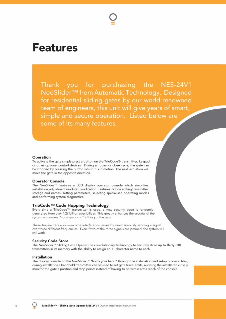
OperationTo activate the gate simply press a button on the TrioCode® transmitter, keypad or other optional control devices. During an open or close cycle, the gate can be stopped by pressing the button whilst it is in motion. The next actuation will move the gate in the opposite direction.
Operator ConsoleThe NeoSlider™ features a LCD display operator console which simplifi es installation, adjustments and status indication. Features include editing transmitter storage and names, setting parameters, selecting specialised operating modes and performing system diagnostics.
TrioCode™ Code Hopping TechnologyEvery time a TrioCode™ transmitter is used, a new security code is randomly generated from over 4.29 billion possibilities. This greatly enhances the security of the system and makes “code grabbing” a thing of the past.
These transmitters also overcome interference issues by simultaneously sending a signal over three different frequencies. Even if two of the three signals are jammed, the system will still work.
Security Code StoreThe NeoSlider™ Sliding Gate Opener uses revolutionary technology to securely store up to thirty (30) transmitters in its memory with the ability to assign an 11 character name to each.
InstallationThe display console on the NeoSlider™ “holds your hand” through the installation and setup process. Also, during installation a handheld transmitter can be used to set gate travel limits, allowing the installer to closely monitor the gate’s position and stop points instead of having to be within arms reach of the console.
Features
Thank you for purchasing the NES-24V1 NeoSlider™ from Automatic Technology. Designed for residential sliding gates by our world renowned team of engineers, this unit will give years of smart, simple and secure operation. Listed below are some of its many features.

Owner Installation Instructions NeoSlider™ - Sliding Gate Opener NES-24V1 7
ISS (Intelligent Safety System)Should the gate hit an obstacle while it is performing a close cycle, or be restricted in some
manner, it will automatically reverse. The amount of force the gate should encounter before reversing is automatically adjusted by the control system during the initialisation of
the automatic opener. The gate will also stop if restricted whilst opening. The Safety Obstruction Force should be checked at least once a month. See installation manual
for instructions.
Status IndicatorThe LCD console display screen indicates through text the status of the NeoSlider™. When the MAIN SCREEN is displayed, the current position of the gate or the result of the last movement can be viewed. The display also shows the countdown timer for Auto-Close operations. Any active input will also be displayed along with the state of various features such as periodic service, battery backup operation and vacation mode.
Control of Lock and LightsThe incorporated controller has dedicated outputs for operating an electric lock and warning or courtesy lights. The timing of these outputs can be adjusted to suit your needs. In addition a button on a remote transmitter can be coded to operate the light output.
Extensive Operating Modes Via Control Inputs And Remote ControlThe integrated controller can be confi gured to operate in many different ways via
the seven (7) control and safety inputs which include P.E, OPEN, STOP, CLOSE, OSC, SWIPE and PEDESTRIAN.
Operation is provided with each transmitter’s button being able to be confi gured to operate one of OSC, PEDESTRIAN, SWIPE, CLOSE, OPEN, STOP, LIGHT or VACATION functions.
The functionality of the transmitter is further enhanced by four (4) Auto-Close modes, three (3) PE Beam response modes and two (2) pedestrian response modes.
SmartSolar™ and Battery Backup Compatibility (optional)The gate opener can be fi tted with a SmartSolar™ or Battery Backup kit for operation in the event of a power outage, or where mains power access is not available.
Manual Operation The gate opener is equipped with a unique manual disengaging device. If the power to the gate opener is disrupted for any reason, the gate can be disengaged via a keylock located on the operator, allowing you to manually open or close the gate.
8 NeoSlider™ - Sliding Gate Opener NES-24V1 Owner Installation Instructions
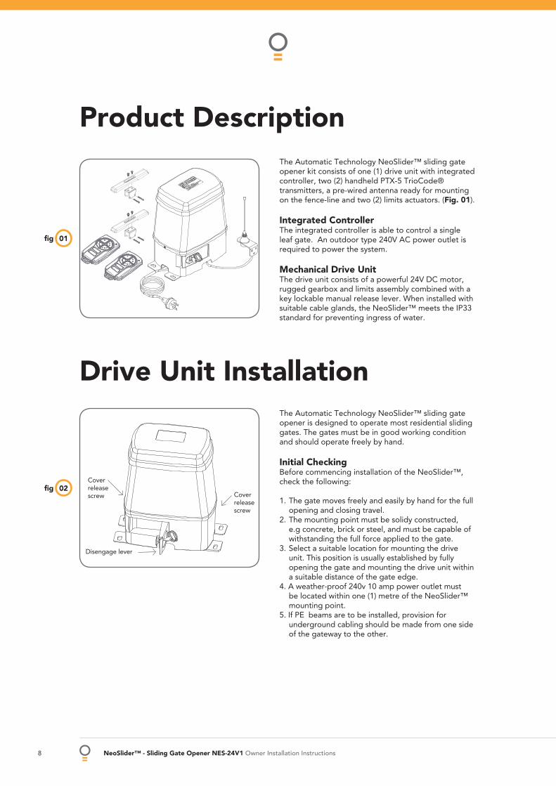
Product DescriptionThe Automatic Technology NeoSlider™ sliding gate opener kit consists of one (1) drive unit with integrated controller, two (2) handheld PTX-5 TrioCode® transmitters, a pre-wired antenna ready for mounting on the fence-line and two (2) limits actuators. (Fig. 01).
Integrated ControllerThe integrated controller is able to control a single leaf gate. An outdoor type 240V AC power outlet is required to power the system.
Mechanical Drive UnitThe drive unit consists of a powerful 24V DC motor, rugged gearbox and limits assembly combined with a key lockable manual release lever. When installed with suitable cable glands, the NeoSlider™ meets the IP33 standard for preventing ingress of water.
01fi g
Drive Unit InstallationThe Automatic Technology NeoSlider™ sliding gate opener is designed to operate most residential sliding gates. The gates must be in good working condition and should operate freely by hand.
Initial CheckingBefore commencing installation of the NeoSlider™, check the following:
1. The gate moves freely and easily by hand for the full opening and closing travel.
2. The mounting point must be solidy constructed, e.g concrete, brick or steel, and must be capable of withstanding the full force applied to the gate.
3. Select a suitable location for mounting the drive unit. This position is usually established by fully opening the gate and mounting the drive unit within a suitable distance of the gate edge.
4. A weather-proof 240v 10 amp power outlet must be located within one (1) metre of the NeoSlider™ mounting point.
5. If PE beams are to be installed, provision for underground cabling should be made from one side of the gateway to the other.
02fi gCover release screw
Disengage lever
Cover release screw

Owner Installation Instructions NeoSlider™ - Sliding Gate Opener NES-24V1 9
Drive Unit Installation
Mounting the Drive UnitThe NeoSlider™ mounting holes are slotted for fi ne adjustment of pinion gear and gate rack alignment. Follow the procedure below to ensure fi nal adjustments can be made later.
We recommend that four 8mm ( 5/16”) or 10mm ( 3/8”) loxins and bolts are used to secure the Drive Unit into position. These loxins usually require a 16mm ( 5/8”) masonry drill bit (if drilling concrete).
1. Prior to mounting the NeoSlider™, determine the distance from the gate to the outer edge of the rack (i.e. the rack width) and to the datum line (see Fig. 03 and Fig. 04). If using an Automatic Technology plastic rack, the width is 40mm. If using a different brand of rack, please ensure it is Module 4 and then confi rm the width, as this will vary.
2. Mark a line parallel to the face of the gate for the mounting holes. The distance from the gate is determined by the formula (38mm + Rack Width). Therefore, if using an Automatic Technology rack, the distance is 78mm. Otherwise, if using a non-Automatic Technology rack, add your rack width (and spacers if required) to the 38mm (see Fig. 03).
3. Another 100mm back, mark another line parallel to that described in point 2 for fi xing. (see Fig. 03). 4. Open the gate to the desired open position. Mark a line at a right angle to the gate 120-150mm from the
open edge of the gate for the mounting holes. 5. Then mark another line 268mm parallel to this line (see Fig. 03). 6. Place the Drive Unit in position where the lines intersect to check the mounting position. If satisfi ed with the
position, remove the Drive Unit. 7. Drill the four mounting holes where the lines intersect. 8. Hammer the loxins into position, place the NeoSlider™ and fi x with the four bolts. Remember when
tightening the bolts to allow fi ne adjustement of the NeoSlider™ later on.
03fi g
Rac
k w
idth
Gate
10 NeoSlider™ - Sliding Gate Opener NES-24V1 Owner Installation Instructions
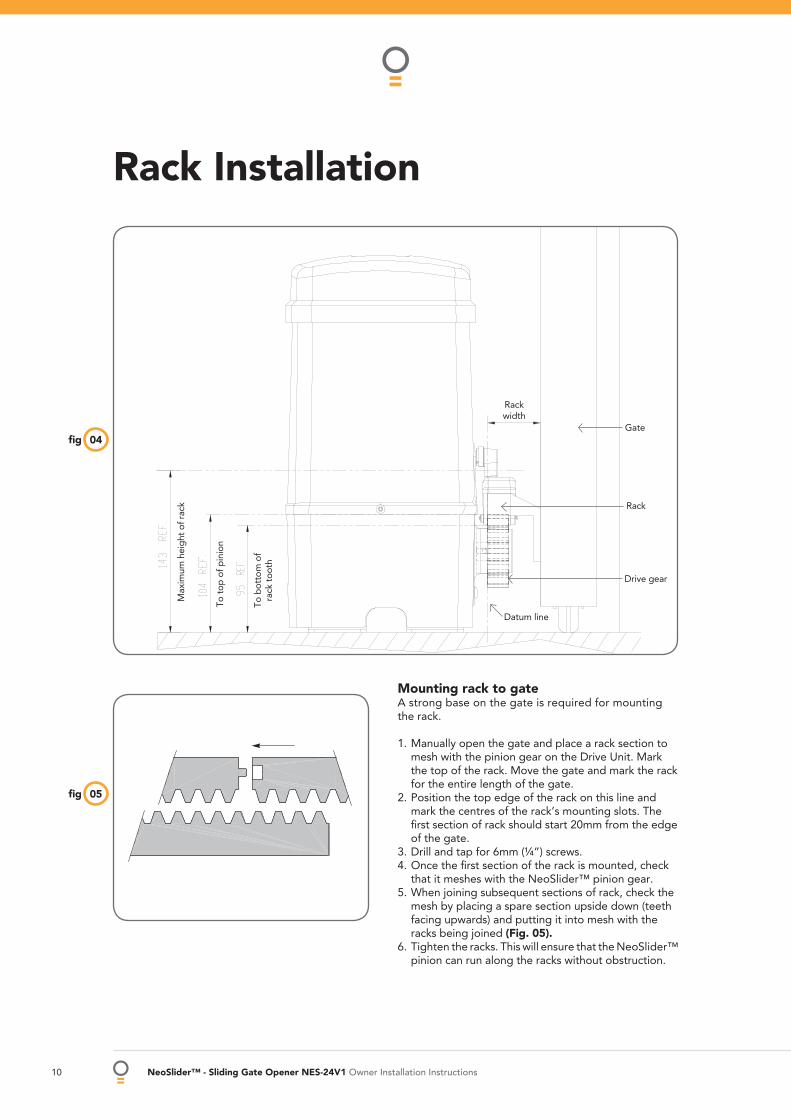
Rack Installation
04fi g
Mounting rack to gateA strong base on the gate is required for mounting the rack.
1. Manually open the gate and place a rack section to mesh with the pinion gear on the Drive Unit. Mark the top of the rack. Move the gate and mark the rack for the entire length of the gate.
2. Position the top edge of the rack on this line and mark the centres of the rack’s mounting slots. The fi rst section of rack should start 20mm from the edge of the gate.
3. Drill and tap for 6mm (¼”) screws.4. Once the fi rst section of the rack is mounted, check
that it meshes with the NeoSlider™ pinion gear.5. When joining subsequent sections of rack, check the
mesh by placing a spare section upside down (teeth facing upwards) and putting it into mesh with the racks being joined (Fig. 05).
6. Tighten the racks. This will ensure that the NeoSlider™ pinion can run along the racks without obstruction.
05fi g
Rack width
Gate
Rack
Drive gear
Datum line
To t
op o
f pin
ion
To b
otto
m o
f ra
ck t
ooth
Max
imum
hei
ght
of r
ack
Owner Installation Instructions NeoSlider™ - Sliding Gate Opener NES-24V1 11
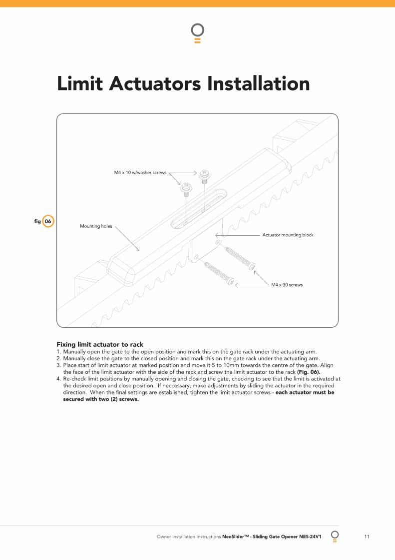
Limit Actuators Installation
Fixing limit actuator to rack1. Manually open the gate to the open position and mark this on the gate rack under the actuating arm.2. Manually close the gate to the closed position and mark this on the gate rack under the actuating arm.3. Place start of limit actuator at marked position and move it 5 to 10mm towards the centre of the gate. Align
the face of the limit actuator with the side of the rack and screw the limit actuator to the rack (Fig. 06).4. Re-check limit positions by manually opening and closing the gate, checking to see that the limit is activated at
the desired open and close position. If neccessary, make adjustments by sliding the actuator in the required direction. When the fi nal settings are established, tighten the limit actuator screws - each actuator must be secured with two (2) screws.
06fi gMounting holes
M4 x 10 w/washer screws
Actuator mounting block
M4 x 30 screws
12 NeoSlider™ - Sliding Gate Opener NES-24V1 Owner Installation Instructions
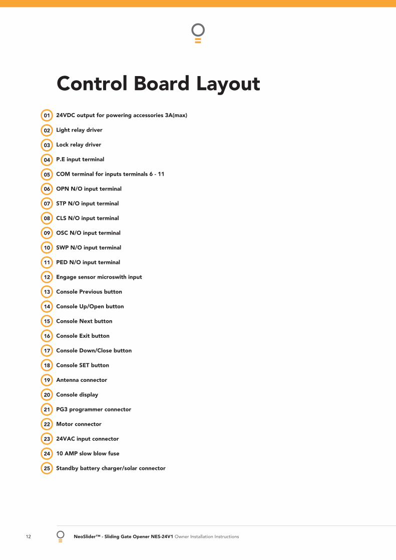
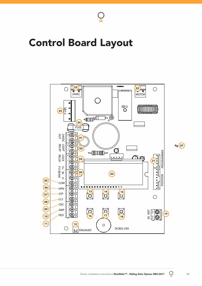
24VDC output for powering accessories 3A(max)
Light relay driver
Lock relay driver
P.E input terminal
COM terminal for inputs terminals 6 - 11
OPN N/O input terminal
STP N/O input terminal
CLS N/O input terminal
OSC N/O input terminal
SWP N/O input terminal
PED N/O input terminal
Engage sensor microswith input
Console Previous button
Console Up/Open button
Console Next button
Console Exit button
Console Down/Close button
Console SET button
Antenna connector
Console display
PG3 programmer connector
Motor connector
24VAC input connector
10 AMP slow blow fuse
Standby battery charger/solar connector
02
01
03
04
05
06
07
08
09
10
11
12
13
14
15
16
17
18
19
20
21
22
23
24
25
Control Board Layout
Owner Installation Instructions NeoSlider™ - Sliding Gate Opener NES-24V1 13
Control Board Layout
ENGAGED
POSI
TIO
NPR
OG
RAM
MER
0V A
NT
24VAC
SBY
-324V
DC
OU
TLIG
HT
RELAYLO
CK
RELAYV
+ IN
V-
P E BEA
M
COM
OPN
STP
CLS
OSC
SWP
PED
MOTOR
FUSE
+ -
+ -
+ -
DCB02-2XX
01
03
02
04
05
06
07
08
09
10
11 12
13 14 15
16 17 1819
20
21
24
25
2223
07fi g
14 NeoSlider™ - Sliding Gate Opener NES-24V1 Owner Installation Instructions
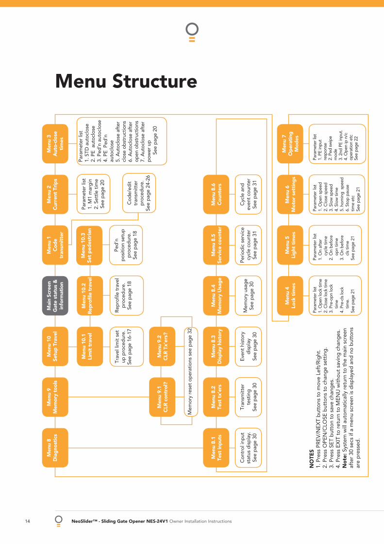
Menu Structure
Men
u 8
Dia
gno
stic
sM
enu
9M
emor
y to
ols
Men
u 10
Setu
p T
rave
lM
enu
1C
ode
tran
smit
ter
Men
u 2
Cur
rent
Tri
ps
Men
u 3
Aut
o-cl
ose
tim
es
Mai
n Sc
reen
Gat
e st
atus
&
info
rmat
ion
Men
u 10
.1Li
mit
tra
vel
Cod
e/ed
it tr
ansm
itter
p
roce
dur
e.
See
pag
e 24
-26
Para
met
er li
st1.
M1
mar
gin
2. S
ettle
tim
eSe
e p
age
20
Para
met
er li
st1.
STD
aut
oclo
se2.
PE
aut
oclo
se3.
Ped
’n a
utoc
lose
4. P
E P
ed’n
au
tocl
ose
5. A
utoc
lose
aft
er
clos
e ob
stru
ctio
ns6.
Aut
oclo
se a
fter
op
en o
bst
ruct
ions
7. A
utoc
lose
aft
er
pow
er u
pSe
e p
age
20
Trav
el li
mit
set
up p
roce
dur
e.
See
pag
e 16
-17
Rep
rofi l
e tr
avel
p
roce
dur
e.
See
pag
e 18
Men
u 9.
1C
LR c
ontr
ol?
Men
u 9.
2C
LR T
x’er
s?
Mem
ory
rese
t op
erat
ions
see
pag
e 32
Men
u 8.
1Te
st in
put
sM
enu
8.2
Test
tx’
ers
Men
u 8.
3D
isp
lay
hist
ory
Men
u 8.
5Se
rvic
e co
unte
rM
enu
8.6
Cou
nter
sM
enu
8.4
Mem
ory
Usa
ge
Con
trol
inp
ut
stat
us d
isp
lay.
Se
e p
age
30
Tran
smitt
er
test
ing
See
pag
e 30
Even
t hi
stor
y d
isp
lay
See
pag
e 30
Perio
dic
ser
vice
cy
cle
coun
ter
See
pag
e 31
Cyc
le a
nd
even
t co
unte
rSe
e p
age
31
Mem
ory
usag
eSe
e p
age
30
Para
met
er li
st
1. O
n af
ter
c
ycle
tim
e 2.
On
bef
ore
o
pn
time
3. O
n b
efor
e
cls
tim
e Se
e p
age
21
Para
met
er li
st
1. O
pen
sp
eed
2. C
lose
sp
eed
3. S
low
sp
eed
4. S
low
tim
e5.
hom
ing
sp
eed
6. S
top
pau
se
time
etc
See
pag
e 21
Para
met
er li
st
1. P
E in
put
resp
onse
2.
Ped
sw
ipe
mod
e3.
2nd
PE
inpu
t.
4. O
pen
ip n
/c
oper
atio
n et
cSe
e pa
ge 2
2
Para
met
er li
st
1. O
pen
lock
tim
e 2.
Clo
se lo
ck ti
me
3. P
re-o
pn lo
ck
tim
e 4.
Pre
-cls
lock
ti
me.
Se
e pa
ge 2
1
NO
TES
1. P
ress
PR
EV/N
EXT
but
tons
to
mov
e Le
ft/R
ight
.2.
Pre
ss O
PEN
/CLO
SE b
utto
ns t
o ch
ang
e se
ttin
g.
3. P
ress
SET
but
ton
to s
ave
chan
ges
.4.
Pre
ss E
XIT
to
retu
rn t
o M
ENU
with
out
savi
ng c
hang
es.
No
te: S
yste
m w
ill a
utom
atic
ally
ret
urn
to t
he m
ain
scre
enaf
ter
30 s
ecs
if a
men
u sc
reen
is d
isp
laye
d a
nd n
o b
utto
nsar
e p
ress
ed.
Men
u 5
Lig
ht t
imes
Men
u 6
Mot
or s
etti
ngs
Men
u 7
Op
erat
ing
M
odes
Men
u 4
Lock
tim
es
Men
u 10
.3Se
t p
edes
tria
n
Ped
’n
pos
ition
set
up
pro
ced
ure.
Se
e p
age
18
Men
u 10
.2R
epro
fi le
tra
vel

Owner Installation Instructions NeoSlider™ - Sliding Gate Opener NES-24V1 15
Initial Electrical Installation
CAUTION: Cables which have a green/yellow coloured insulation are for earthing purposes only. Never use these cables for any other purpose.
Warning: A qualifi ed electrician must perform the installation where 240V AC power is used.
16 NeoSlider™ - Sliding Gate Opener NES-24V1 Owner Installation Instructions
Setting Travel Limits
MENU 10.1Limit Travel
PR E S S
10fi g
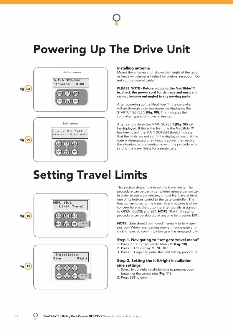
Installing antennaMount the antenna at or above the height of the gate or fence (whichever is higher) for optimal reception. Do not cut the coaxial cable.
PLEASE NOTE - Before plugging the NeoSlider™ in, check the power cord for damage and ensure it cannot become entangled in any moving parts
After powering up the NeoSlider™, the controller will go through a startup sequence displaying the STARTUP SCREEN (Fig. 08). This indicates the controller type and fi rmware version.
After a short delay the MAIN SCREEN (Fig. 09) will be displayed. If this is the fi rst time the NeoSlider™ has been used, the MAIN SCREEN should indicate that the limits are not set. If the display shows that the gate is disengaged or an input is active, then rectify the situation before continuing with the procedure for setting the travel limits for a single gate.
Powering Up The Drive Unit
08fi g
09fi g
This section shows how to set the travel limits. The procedure can be partly completed using a transmitter. In order to use a transmitter, it must fi rst have at least one of its buttons coded to the gate controller. The function assigned to the transmitter’s buttons is of no concern here as the buttons are temporally assigned to OPEN, CLOSE and SET. NOTE: The limit setting procedure can be aborted at anytime by pressing EXIT.
NOTE: Gate should be moved manually to fully open position. When re-engaging opener, nudge gate until click is heard to confi rm pinion gear has engaged fully.
Step 1. Navigating to “set gate travel menu” 1. Press PREV to navigate to Menu 10 (Fig. 10). 2. Press SET to display MENU 10.1. 3. Press SET again to enter the limit setting procedure. Step 2. Setting the left/right installation side settings 1. Select left or right installation side by pressing open
button for the correct side (Fig. 11). 2. Press SET to confi rm.
A.T.A NNES-24V1Firmware #.##
Start up screen
Main screen
InstallationSide Right
PR E S S
11fi g
Owner Installation Instructions NeoSlider™ - Sliding Gate Opener NES-24V1 17
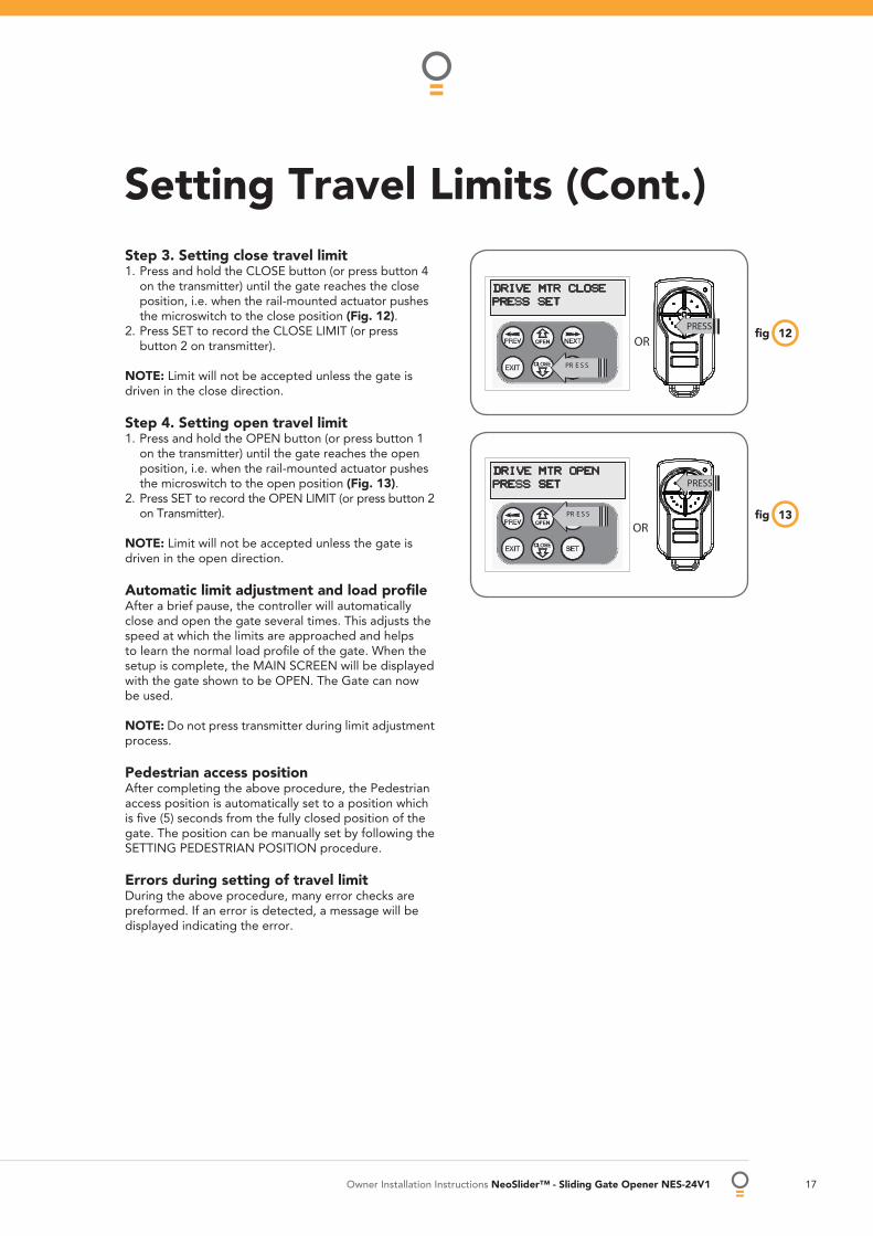
Step 3. Setting close travel limit 1. Press and hold the CLOSE button (or press button 4
on the transmitter) until the gate reaches the close position, i.e. when the rail-mounted actuator pushes the microswitch to the close position (Fig. 12).
2. Press SET to record the CLOSE LIMIT (or press button 2 on transmitter).
NOTE: Limit will not be accepted unless the gate is driven in the close direction.
Step 4. Setting open travel limit1. Press and hold the OPEN button (or press button 1
on the transmitter) until the gate reaches the open position, i.e. when the rail-mounted actuator pushes the microswitch to the open position (Fig. 13).
2. Press SET to record the OPEN LIMIT (or press button 2 on Transmitter).
NOTE: Limit will not be accepted unless the gate is driven in the open direction.
Automatic limit adjustment and load profi le After a brief pause, the controller will automatically close and open the gate several times. This adjusts the speed at which the limits are approached and helps to learn the normal load profi le of the gate. When the setup is complete, the MAIN SCREEN will be displayed with the gate shown to be OPEN. The Gate can now be used.
NOTE: Do not press transmitter during limit adjustment process.
Pedestrian access position After completing the above procedure, the Pedestrian access position is automatically set to a position which is fi ve (5) seconds from the fully closed position of the gate. The position can be manually set by following the SETTING PEDESTRIAN POSITION procedure.
Errors during setting of travel limit During the above procedure, many error checks are preformed. If an error is detected, a message will be displayed indicating the error.
12fi g
PRESS SET
PR E S S
OR
DRIVE MTR CLOSE
PRESS
PR E S S
OR
PRESS SETDRIVE MTR OPEN
PRESS
13fi g
Setting Travel Limits (Cont.)

18 NeoSlider™ - Sliding Gate Opener NES-24V1 Owner Installation Instructions
Note: The pedestrian default position is set at fi ve (5) seconds from fully closed position and can be changed as follows:
Step 1. Navigating to “set pedestrian menu” 1. Press PREV to navigate to Menu 10 (Fig. 14). 2. Press SET - MENU 10.1 is displayed. 3. Press NEXT to go to MENU 10.3. 4. Press SET to enter Set Pedestrian procedure.
Step 2. Setting pedestrian position 1. Press OPEN to change the pedestrian access position
time (Fig. 15). 2. Press SET to record new time Step 3. Pedestrian position set The controller will return to the MAIN SCREEN with the gate status shown as being in pedestrian access mode (Fig. 16).
Setting Pedestrian Position
MENU 10.3Set Pedestrian
PR E S S
14fi g
16fi g
Ped’n OpeningTime 5
PR E S S
PR E S S
15fi g
Recalculate Force MarginsReprofi ling is a simplifi ed way of re-learning the travel characteristic of a previously setup Limit Switch travel installation. Re-profi ling can be used when the travel characteristics of the gate change due to mechanical adjustments etc. To initiate a re-profi le simply locate “MENU 10.3 Reprofi le Travel” and press SET then follow the prompts. The gate will start to move and re-calculate force margins. The gate can move between the open and close limit positions up to two (2) times (depending on the position of the gate and the power up condition). A single beep will be heard once the process is complete and setup complete message will be displayed
a.
b.
Reprofi le Travel
Owner Installation Instructions NeoSlider™ - Sliding Gate Opener NES-24V1 19
This section describes the standard operation of the control board with the factory set default values.
Motor controlThe controller drives the motor in the direction determined by the control inputs. Once a cycle is started, the motors will continue to travel until:
1. The controller is instructed to stop by a control input; or;
2. The motor’s travel limit is reached; or,3. The motor is obstructed, overloaded or stalls. When the control inputs instruct the control board to change the motor direction, the controller brakes the motor, waits for the gate to stop moving and then starts the motor in the opposite direction.
Motor Obstruction DetectionIf the gate is obstructed while opening, it will stop. If it is obstructed while closing, gate will stop and then reverse to the open position. Obstruction Detection monitors the motor’s speed and compares it to the “normal” speed profi le for the motor. If the speed of a motor falls below “normal” then the motor is said to be obstructed. In addition to the normal motor obstruction detection, motor overload and stall detection is provided to protect the gate and opener.
Motor speed control - SOFT START/SOFT STOPThe motor’s speed is microprocessor controlled, ramping up speed as the gate starts to move, and ramping down as it approaches the travel limits to provide a gentle stop.
Lock release output The lock release output is confi gured to pulse for 0.5 seconds at the start of each cycle. The output is turned on at the same time the motor is activated.
Courtesy light Courtesy lights can be activated with the addition of a module connected to the control board. Normally used as a safety device to illuminate the area and warn pedestrians, the light will turn on each time the gate is activated (day or night) and automatically turn off one (1) minute after the cycle has fi nished. The light can also be activated and deactivated by pressing a transmitter button assigned the LGT function.
OPEN/STOP/CLOSE (OSC) input (Activated by OSC terminal with N/O switch or by transmitter button with OSC function assigned). If the gate is moving, the OSC input will cause the gate to stop. The next trigger will move the gate in the opposite direction to the last travelled.
Pedestrian access (PED) function (Activated by PED terminal with N/O switch or by transmitter button with PED function assigned). The pedestrian access operation opens the gate partially to allow pedestrian access but prevent vehicle access. The position the gate leaf is driven to is automatically set to fi ve (5) seconds from the closed position during setting of the travel limits, but can be adjusted to suit. Close (CLS) input (Activated by CLS terminal with N/O switch, by transmitter button with CLS function assigned or by CLOSE button on console). Activating the CLS input will cause the gate to close. Holding the input active will prevent opening.
Swipe Card (SWP) input (Activated by SWP terminal with N/O switch or by transmitter button with SWP function assigned). Activating the SWP input will cause the gate to be opened. If the terminal input is held it will prevent the gate from being closed. The swipe input also effects PE TRIGGERED AUTO CLOSE.
Open (OPN) input (Activated by OPN terminal with N/C switch, by transmitter button with OPN function assigned or by OPEN button on console). Activating the OPN input will cause the gate to open. Holding the input will prevent closing.
Stop (STP) input (Activated by STP terminal with N/C switch, by transmitter button with STP function assigned or by EXIT button on console). Activating the STP input while the gate is moving will cause the gate to be stopped. If the STP terminal is held it will prevent the gate from being moved.
Photo Electric (PE) safety beam input (Activated by PE terminal with N/C switch) When the PE input is active, the gate is prevented from being closed. If the PE input is triggered while the gate is closing, the controller will stop the motors and then open the gate. The PE input has no effect while the gate is opening.
Vacation mode Vacation mode blocks all but one designated remote transmitter from activating the NeoSlider™. The mode is activated by pressing a transmitter button with the VAC function assigned until the console displays that vacation mode is enabled (approx. 5 secs). When activated, any transmitter button which is assigned VAC will be ignored. To turn Vacation mode off, press a transmitter button with the VAC function assigned. Vacation mode can also be turned on or off manually by editing the VACATION MODE parameter.
Standard Operating Modes
20 NeoSlider™ - Sliding Gate Opener NES-24V1 Owner Installation Instructions
The opener’s standard operation can be altered by editing various parameters. This section describes the parameters and the effect they have. Use the VIEWING AND EDITING PARAMETER PROCEDURE on Page 23 to make changes.
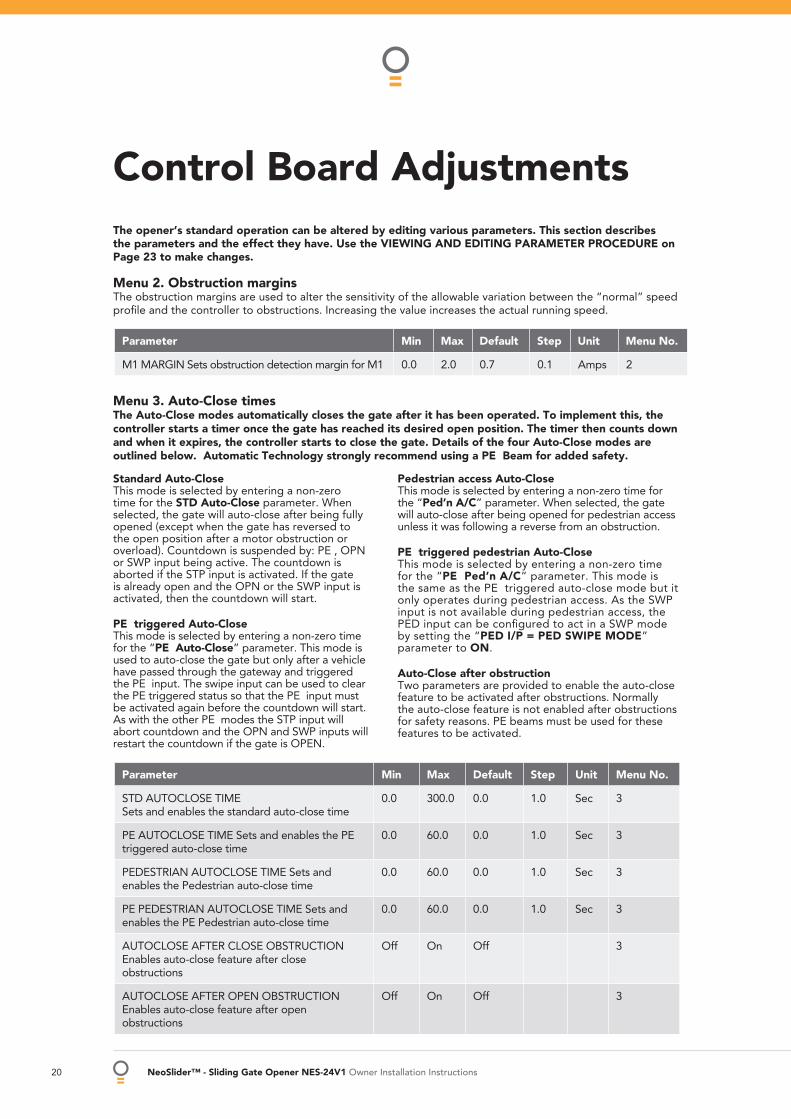
Menu 2. Obstruction margins The obstruction margins are used to alter the sensitivity of the allowable variation between the “normal” speed profi le and the controller to obstructions. Increasing the value increases the actual running speed.
Control Board Adjustments
Parameter Min Max Default Step Unit Menu No.
M1 MARGIN Sets obstruction detection margin for M1 0.0 2.0 0.7 0.1 Amps 2
Standard Auto-Close This mode is selected by entering a non-zero time for the STD Auto-Close parameter. When selected, the gate will auto-close after being fully opened (except when the gate has reversed to the open position after a motor obstruction or overload). Countdown is suspended by: PE , OPN or SWP input being active. The countdown is aborted if the STP input is activated. If the gate is already open and the OPN or the SWP input is activated, then the countdown will start.
PE triggered Auto-Close This mode is selected by entering a non-zero time for the “PE Auto-Close” parameter. This mode is used to auto-close the gate but only after a vehicle have passed through the gateway and triggered the PE input. The swipe input can be used to clear the PE triggered status so that the PE input must be activated again before the countdown will start. As with the other PE modes the STP input will abort countdown and the OPN and SWP inputs will restart the countdown if the gate is OPEN.
Pedestrian access Auto-Close This mode is selected by entering a non-zero time for the “Ped’n A/C” parameter. When selected, the gate will auto-close after being opened for pedestrian access unless it was following a reverse from an obstruction.
PE triggered pedestrian Auto-Close This mode is selected by entering a non-zero time for the “PE Ped’n A/C” parameter. This mode is the same as the PE triggered auto-close mode but it only operates during pedestrian access. As the SWP input is not available during pedestrian access, the PED input can be confi gured to act in a SWP mode by setting the “PED I/P = PED SWIPE MODE” parameter to ON. Auto-Close after obstruction Two parameters are provided to enable the auto-close feature to be activated after obstructions. Normally the auto-close feature is not enabled after obstructions for safety reasons. PE beams must be used for these features to be activated.
Parameter Min Max Default Step Unit Menu No.
STD AUTOCLOSE TIME Sets and enables the standard auto-close time
0.0 300.0 0.0 1.0 Sec 3
PE AUTOCLOSE TIME Sets and enables the PE triggered auto-close time
0.0 60.0 0.0 1.0 Sec 3
PEDESTRIAN AUTOCLOSE TIME Sets and enables the Pedestrian auto-close time
0.0 60.0 0.0 1.0 Sec 3
PE PEDESTRIAN AUTOCLOSE TIME Sets and enables the PE Pedestrian auto-close time
0.0 60.0 0.0 1.0 Sec 3
AUTOCLOSE AFTER CLOSE OBSTRUCTION Enables auto-close feature after close obstructions
Off On Off 3
AUTOCLOSE AFTER OPEN OBSTRUCTION Enables auto-close feature after open obstructions
Off On Off 3
Menu 3. Auto-Close times The Auto-Close modes automatically closes the gate after it has been operated. To implement this, the controller starts a timer once the gate has reached its desired open position. The timer then counts down and when it expires, the controller starts to close the gate. Details of the four Auto-Close modes are outlined below. Automatic Technology strongly recommend using a PE Beam for added safety.
Owner Installation Instructions NeoSlider™ - Sliding Gate Opener NES-24V1 21
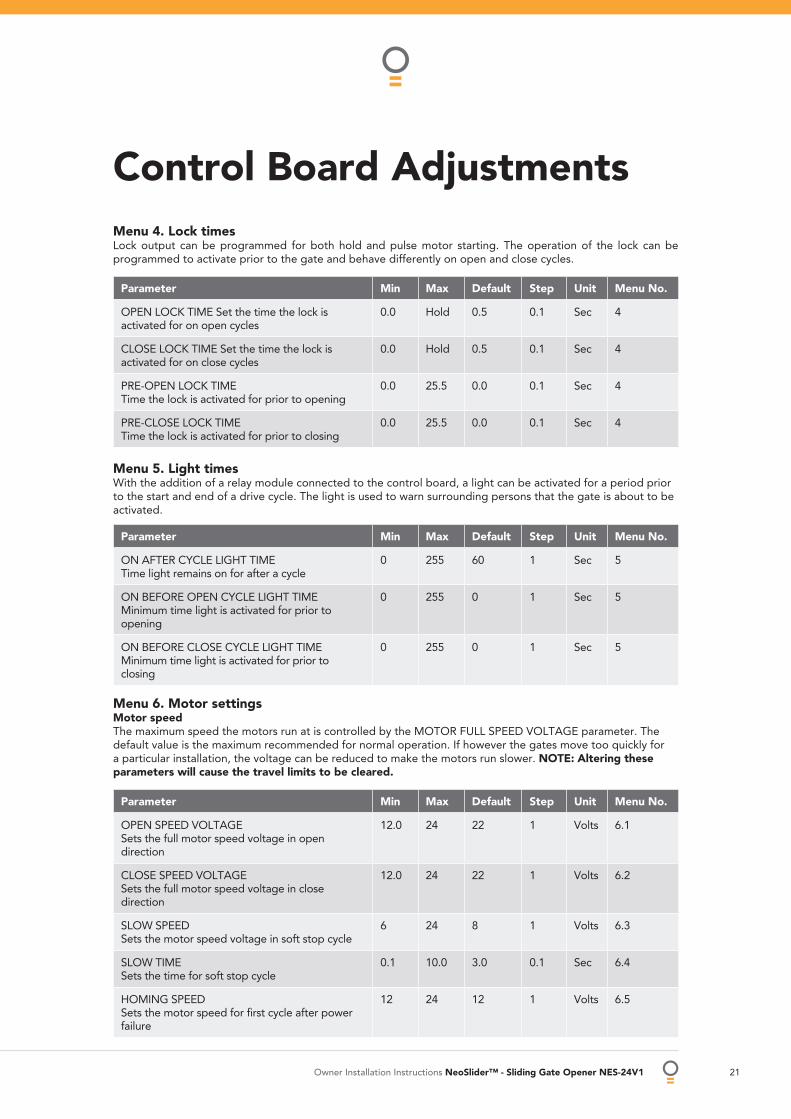
Menu 4. Lock times Lock output can be programmed for both hold and pulse motor starting. The operation of the lock can be programmed to activate prior to the gate and behave differently on open and close cycles.
Control Board Adjustments
Parameter Min Max Default Step Unit Menu No.
OPEN LOCK TIME Set the time the lock is activated for on open cycles
0.0 Hold 0.5 0.1 Sec 4
CLOSE LOCK TIME Set the time the lock is activated for on close cycles
0.0 Hold 0.5 0.1 Sec 4
PRE-OPEN LOCK TIME Time the lock is activated for prior to opening
0.0 25.5 0.0 0.1 Sec 4
PRE-CLOSE LOCK TIME Time the lock is activated for prior to closing
0.0 25.5 0.0 0.1 Sec 4
Menu 5. Light times With the addition of a relay module connected to the control board, a light can be activated for a period prior to the start and end of a drive cycle. The light is used to warn surrounding persons that the gate is about to be activated.
Parameter Min Max Default Step Unit Menu No.
ON AFTER CYCLE LIGHT TIME Time light remains on for after a cycle
0 255 60 1 Sec 5
ON BEFORE OPEN CYCLE LIGHT TIME Minimum time light is activated for prior to opening
0 255 0 1 Sec 5
ON BEFORE CLOSE CYCLE LIGHT TIME Minimum time light is activated for prior to closing
0 255 0 1 Sec 5
Menu 6. Motor settings Motor speedThe maximum speed the motors run at is controlled by the MOTOR FULL SPEED VOLTAGE parameter. The default value is the maximum recommended for normal operation. If however the gates move too quickly for a particular installation, the voltage can be reduced to make the motors run slower. NOTE: Altering these parameters will cause the travel limits to be cleared.
Parameter Min Max Default Step Unit Menu No.
OPEN SPEED VOLTAGE Sets the full motor speed voltage in open direction
12.0 24 22 1 Volts 6.1
CLOSE SPEED VOLTAGESets the full motor speed voltage in close direction
12.0 24 22 1 Volts 6.2
SLOW SPEEDSets the motor speed voltage in soft stop cycle
6 24 8 1 Volts 6.3
SLOW TIMESets the time for soft stop cycle
0.1 10.0 3.0 0.1 Sec 6.4
HOMING SPEEDSets the motor speed for fi rst cycle after power failure
12 24 12 1 Volts 6.5
22 NeoSlider™ - Sliding Gate Opener NES-24V1 Owner Installation Instructions
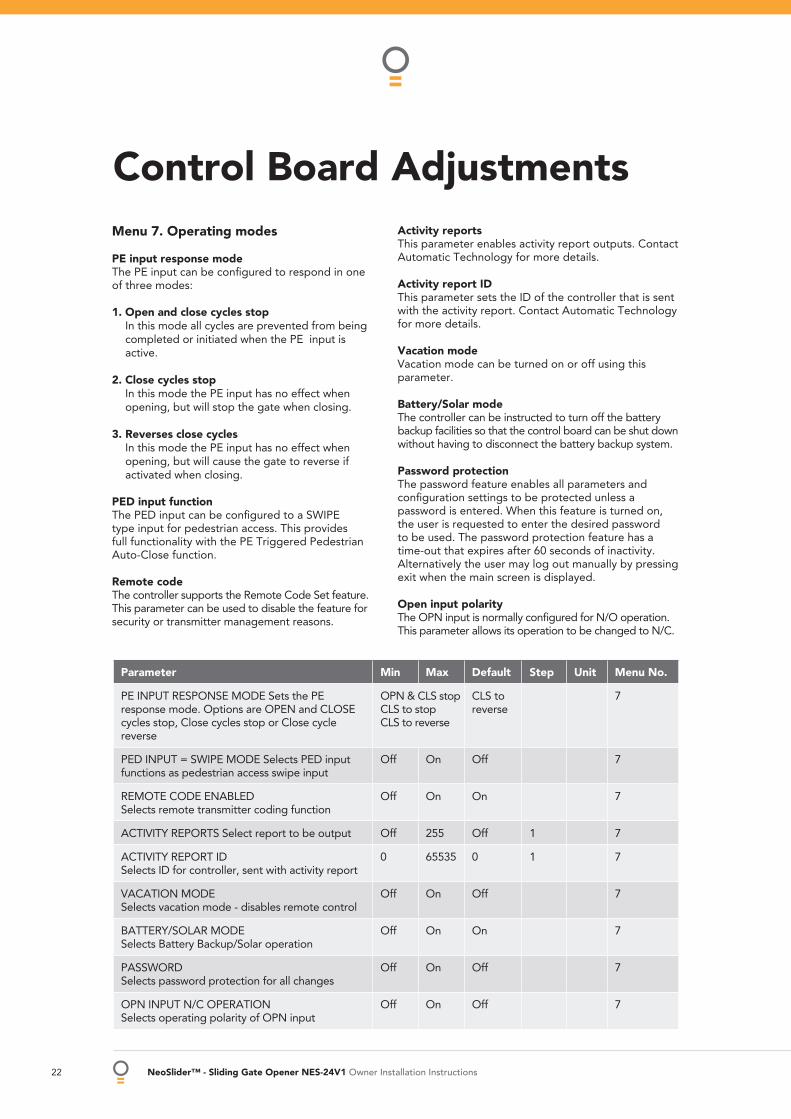
Menu 7. Operating modes
PE input response mode The PE input can be confi gured to respond in one of three modes:
1. Open and close cycles stop In this mode all cycles are prevented from being
completed or initiated when the PE input is active.
2. Close cycles stop In this mode the PE input has no effect when
opening, but will stop the gate when closing.
3. Reverses close cycles In this mode the PE input has no effect when
opening, but will cause the gate to reverse if activated when closing.
PED input function The PED input can be confi gured to a SWIPE type input for pedestrian access. This provides full functionality with the PE Triggered Pedestrian Auto-Close function.
Remote code The controller supports the Remote Code Set feature. This parameter can be used to disable the feature for security or transmitter management reasons.
Activity reports This parameter enables activity report outputs. Contact Automatic Technology for more details.
Activity report IDThis parameter sets the ID of the controller that is sent with the activity report. Contact Automatic Technology for more details.
Vacation mode Vacation mode can be turned on or off using this parameter.
Battery/Solar mode The controller can be instructed to turn off the battery backup facilities so that the control board can be shut down without having to disconnect the battery backup system.
Password protection The password feature enables all parameters and confi guration settings to be protected unless a password is entered. When this feature is turned on, the user is requested to enter the desired password to be used. The password protection feature has a time-out that expires after 60 seconds of inactivity. Alternatively the user may log out manually by pressing exit when the main screen is displayed.
Open input polarity The OPN input is normally confi gured for N/O operation. This parameter allows its operation to be changed to N/C.
Parameter Min Max Default Step Unit Menu No.
PE INPUT RESPONSE MODE Sets the PE response mode. Options are OPEN and CLOSE cycles stop, Close cycles stop or Close cycle reverse
OPN & CLS stopCLS to stopCLS to reverse
CLS to reverse
7
PED INPUT = SWIPE MODE Selects PED input functions as pedestrian access swipe input
Off On Off 7
REMOTE CODE ENABLED Selects remote transmitter coding function
Off On On 7
ACTIVITY REPORTS Select report to be output Off 255 Off 1 7
ACTIVITY REPORT ID Selects ID for controller, sent with activity report
0 65535 0 1 7
VACATION MODE Selects vacation mode - disables remote control
Off On Off 7
BATTERY/SOLAR MODE Selects Battery Backup/Solar operation
Off On On 7
PASSWORD Selects password protection for all changes
Off On Off 7
OPN INPUT N/C OPERATION Selects operating polarity of OPN input
Off On Off 7
Control Board Adjustments
Owner Installation Instructions NeoSlider™ - Sliding Gate Opener NES-24V1 23
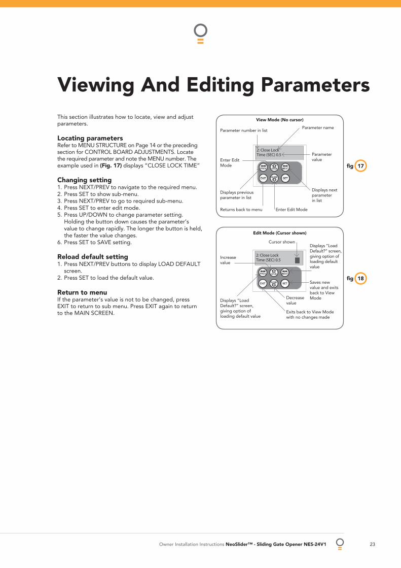
Viewing And Editing Parameters This section illustrates how to locate, view and adjust parameters.
Locating parameters Refer to MENU STRUCTURE on Page 14 or the preceding section for CONTROL BOARD ADJUSTMENTS. Locate the required parameter and note the MENU number. The example used in (Fig. 17) displays “CLOSE LOCK TIME”
Changing setting 1. Press NEXT/PREV to navigate to the required menu. 2. Press SET to show sub-menu. 3. Press NEXT/PREV to go to required sub-menu. 4. Press SET to enter edit mode. 5. Press UP/DOWN to change parameter setting.
Holding the button down causes the parameter’s value to change rapidly. The longer the button is held, the faster the value changes.
6. Press SET to SAVE setting.
Reload default setting 1. Press NEXT/PREV buttons to display LOAD DEFAULT
screen. 2. Press SET to load the default value.
Return to menu If the parameter’s value is not to be changed, press EXIT to return to sub menu. Press EXIT again to return to the MAIN SCREEN.
17fi g
18fi g
Parameter name
Parameter value
Displays next parameter in list
Parameter number in list
Enter Edit Mode
Displays previous parameter in list
Returns back to menu Enter Edit Mode
View Mode (No cursor)
Edit Mode (Cursor shown)
Increase value
Displays “Load Default?” screen, giving option of loading default value
Exits back to View Mode with no changes made
Decrease value
Saves new value and exits back to View Mode
Displays “Load Default?” screen, giving option of loading default value
Cursor shown
24 NeoSlider™ - Sliding Gate Opener NES-24V1 Owner Installation Instructions
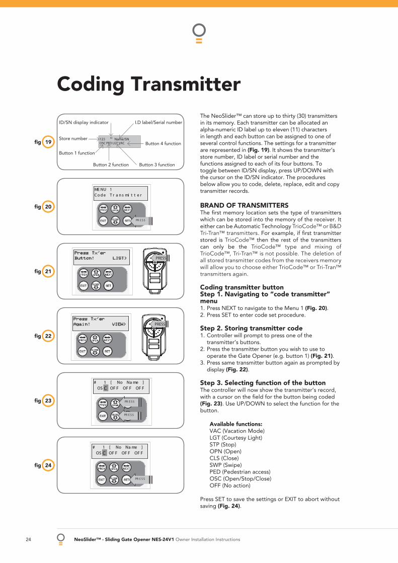
Coding Transmitter The NeoSlider™ can store up to thirty (30) transmitters in its memory. Each transmitter can be allocated an alpha-numeric ID label up to eleven (11) characters in length and each button can be assigned to one of several control functions. The settings for a transmitter are represented in (Fig. 19). It shows the transmitter’s store number, ID label or serial number and the functions assigned to each of its four buttons. To toggle between ID/SN display, press UP/DOWN with the cursor on the ID/SN indicator. The procedures below allow you to code, delete, replace, edit and copy transmitter records.
BRAND OF TRANSMITTERSThe fi rst memory location sets the type of transmitters which can be stored into the memory of the receiver. It either can be Automatic Technology TrioCode™ or B&D Tri-Tran™ transmitters. For example, if fi rst transmitter stored is TrioCode™ then the rest of the transmitters can only be the TrioCode™ type and mixing of TrioCode™, Tri-Tran™ is not possible. The deletion of all stored transmitter codes from the receivers memory will allow you to choose either TrioCode™ or Tri-Tran™ transmitters again.
Coding transmitter button Step 1. Navigating to “code transmitter” menu 1. Press NEXT to navigate to the Menu 1 (Fig. 20). 2. Press SET to enter code set procedure.
Step 2. Storing transmitter code 1. Controller will prompt to press one of the
transmitter’s buttons. 2. Press the transmitter button you wish to use to
operate the Gate Opener (e.g. button 1) (Fig. 21). 3. Press same transmitter button again as prompted by
display (Fig. 22).
Step 3. Selecting function of the button The controller will now show the transmitter’s record, with a cursor on the fi eld for the button being coded (Fig. 23). Use UP/DOWN to select the function for the button.
Available functions: VAC (Vacation Mode) LGT (Courtesy Light) STP (Stop) OPN (Open) CLS (Close) SWP (Swipe) PED (Pedestrian access) OSC (Open/Stop/Close) OFF (No action)
Press SET to save the settings or EXIT to abort without saving (Fig. 24).
21fi g
22fi g
23fi g
24fi g
Press Tx’erAgain! VIEW> PRESS
20fi g
Press Tx’erButton! LIST> PRESS
19fi g
I.D label/Serial number
Button 4 function
Button 3 functionButton 2 function
Button 1 function
Store number
ID/SN display indicator
Owner Installation Instructions NeoSlider™ - Sliding Gate Opener NES-24V1 25
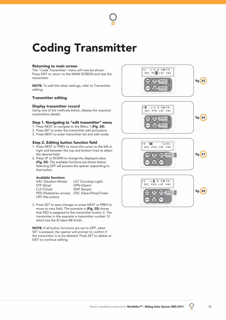
Returning to main screen The “Code Transmitter” menu will now be shown. Press EXIT to return to the MAIN SCREEN and test the transmitter.
NOTE: To edit the other settings, refer to Transmitter editing.
Transmitter editing
Display transmitter record Using one of the methods below, display the required transmitters details.
Step 1. Navigating to “edit transmitter” menu 1. Press NEXT to navigate to the Menu 1 (Fig. 20). 2. Press SET to enter the transmitter edit procedure. 3. Press NEXT to enter transmitter list and edit mode.
Step 2. Editing button function fi eld 1. Press NEXT or PREV to move the cursor to the left or
right and between the top and bottom lines to select the desired fi eld.
2. Press UP or DOWN to change the displayed value (Fig. 25). The available functions are shown below. Selecting OFF will prevent the opener responding to that button.
Available functions VAC (Vacation Mode) LGT (Courtesy Light) STP (Stop) OPN (Open) CLS (Close) SWP (Swipe) PED (Pedestrian access) OSC (Open/Stop/Close) OFF (No action)
3. Press SET to save changes or press NEXT or PREV to move to next fi eld. The example in (Fig. 25) shows that PED is assigned to the transmitter button 2. The transmitter in the example is transmitter number 12 which has the ID label AB Smith.
NOTE: If all button functions are set to OFF, when SET is pressed, the opener will prompt to confi rm if the transmitter is to be deleted. Press SET to delete or EXIT to continue editing.
27fi g
28fi g
26fi g
25fi g
Coding Transmitter
26 NeoSlider™ - Sliding Gate Opener NES-24V1 Owner Installation Instructions
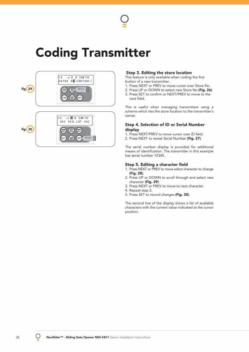
Step 3. Editing the store location This feature is only available when coding the fi rst button of a new transmitter. 1. Press NEXT or PREV to move cursor over Store No. 2. Press UP or DOWN to select new Store No (Fig. 26). 3. Press SET to confi rm or NEXT/PREV to move to the
next fi eld.
This is useful when managing transmitters using a scheme which ties the store location to the transmitter’s owner.
Step 4. Selection of ID or Serial Number display 1. Press NEXT/PREV to move cursor over ID fi eld. 2. Press NEXT to reveal Serial Number (Fig. 27).
The serial number display is provided for additional means of identifi cation. The transmitter in this example has serial number 12345.
Step 5. Editing a character fi eld 1. Press NEXT or PREV to move select character to change
(Fig. 28). 2. Press UP or DOWN to scroll through and select new
character (Fig. 29). 3. Press NEXT or PREV to move to next character. 4. Repeat step 2. 5. Press SET to record changes (Fig. 30).
The second line of the display shows a list of available characters with the current value indicated at the cursor position.
29fi g
30fi g
Coding Transmitter
Owner Installation Instructions NeoSlider™ - Sliding Gate Opener NES-24V1 27
Transmitter Management
33fi g
34fi g
35fi g
36fi g
Press Tx’erButton! LIST> PRESS
31fi g
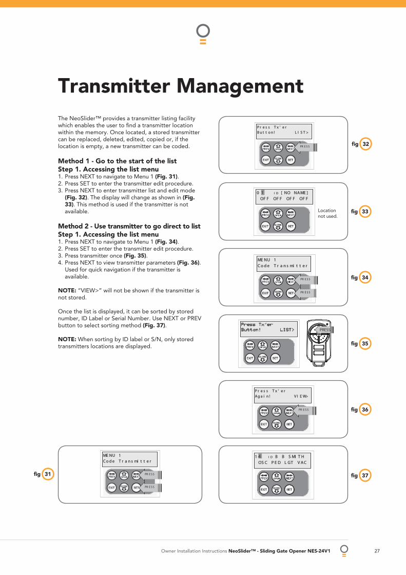
The NeoSlider™ provides a transmitter listing facility which enables the user to fi nd a transmitter location within the memory. Once located, a stored transmitter can be replaced, deleted, edited, copied or, if the location is empty, a new transmitter can be coded.
Method 1 - Go to the start of the list Step 1. Accessing the list menu 1. Press NEXT to navigate to Menu 1 (Fig. 31). 2. Press SET to enter the transmitter edit procedure. 3. Press NEXT to enter transmitter list and edit mode
(Fig. 32). The display will change as shown in (Fig. 33). This method is used if the transmitter is not available.
Method 2 - Use transmitter to go direct to list Step 1. Accessing the list menu 1. Press NEXT to navigate to Menu 1 (Fig. 34). 2. Press SET to enter the transmitter edit procedure. 3. Press transmitter once (Fig. 35). 4. Press NEXT to view transmitter parameters (Fig. 36).
Used for quick navigation if the transmitter is available.
NOTE: “VIEW>” will not be shown if the transmitter is not stored.
Once the list is displayed, it can be sorted by stored number, ID Label or Serial Number. Use NEXT or PREV button to select sorting method (Fig. 37).
NOTE: When sorting by ID label or S/N, only stored transmitters locations are displayed.
37fi g
Location not used.
32fi g

28 NeoSlider™ - Sliding Gate Opener NES-24V1 Owner Installation Instructions
Step 2. Navigating the list 1. Press UP or DOWN buttons to navigate through the
list (Fig. 38). 2. Press SET to display menu of available functions.
NOTE: Holding a button down will step through the list faster.
Selecting an operation Press NEXT or PREV to cycle through the four menu options (Fig. 39-42). Press EXIT to return to the list. Press SET to execute the menu’s operation.
Code operation (location empty) If the code operation is selected on an empty transmitter location, the BASIC CODE TRANSMITTER PROCEDURE will be initiated with the transmitter being saved in the selected location. This is useful when managing transmitters using a scheme which ties the store location to the transmitter’s owner.
Code operation (location used) If the code operation is selected for a location that already contains a transmitter, then the BASIC CODE TRANSMITTER PROCEDURE will be initiated and the new transmitter will replace the existing one. Note that the button functions and name of the existing transmitter will be transferred to the new transmitter. This procedure is of great convenience when replacing a lost transmitter.
Delete operation The delete operation is used to remove a transmitter from memory along with the name and button function settings.
Edit operation The edit operation displays the transmitter record for editing purposes. See TRANSMITTER EDIT PROCEDURE for details.
Copy operation The copy operation is used to code multiple transmitters with the same button function as that of the selected transmitter. Once selected an abbreviated code set routine is initiated which repeats steps 2 & 3 of the BASIC CODE TRANSMITTER PROCEDURE for each transmitter to be coded. Coding is terminated by pressing the EXIT button.
Exiting the list To exit the transmitter list, simply press EXIT to return to the code transmitter menu.
Transmitter Management
38fi g
40fi g
41fi g
39fi g
42fi g
Owner Installation Instructions NeoSlider™ - Sliding Gate Opener NES-24V1 29
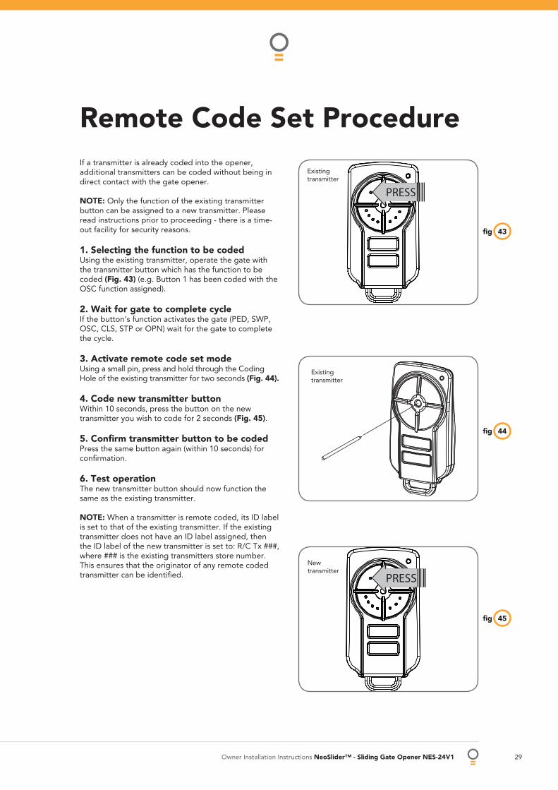
Remote Code Set Procedure If a transmitter is already coded into the opener, additional transmitters can be coded without being in direct contact with the gate opener.
NOTE: Only the function of the existing transmitter button can be assigned to a new transmitter. Please read instructions prior to proceeding - there is a time-out facility for security reasons.
1. Selecting the function to be coded Using the existing transmitter, operate the gate with the transmitter button which has the function to be coded (Fig. 43) (e.g. Button 1 has been coded with the OSC function assigned).
2. Wait for gate to complete cycle If the button’s function activates the gate (PED, SWP, OSC, CLS, STP or OPN) wait for the gate to complete the cycle.
3. Activate remote code set mode Using a small pin, press and hold through the Coding Hole of the existing transmitter for two seconds (Fig. 44).
4. Code new transmitter button Within 10 seconds, press the button on the new transmitter you wish to code for 2 seconds (Fig. 45).
5. Confi rm transmitter button to be coded Press the same button again (within 10 seconds) for confi rmation.
6. Test operation The new transmitter button should now function the same as the existing transmitter.
NOTE: When a transmitter is remote coded, its ID label is set to that of the existing transmitter. If the existing transmitter does not have an ID label assigned, then the ID label of the new transmitter is set to: R/C Tx ###, where ### is the existing transmitters store number. This ensures that the originator of any remote coded transmitter can be identifi ed.
43fi g
44fi g
Existing transmitter
New transmitter
PRESS
PRESS
Existing transmitter
45fi g
30 NeoSlider™ - Sliding Gate Opener NES-24V1 Owner Installation Instructions
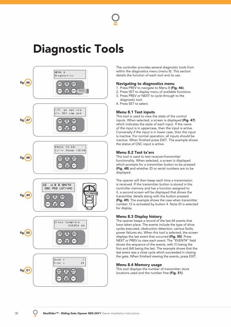
Diagnostic ToolsThe controller provides several diagnostic tools from within the diagnostics menu (menu 8). This section details the function of each tool and its use.
Navigating to diagnostics menu 1. Press PREV to navigate to Menu 8 (Fig. 46). 2. Press SET to display menu of available functions. 3. Press PREV or NEXT to cycle through to the
diagnostic tool. 4. Press SET to select.
Menu 8.1 Test inputs This tool is used to view the state of the control inputs. When selected, a screen is displayed (Fig. 47) which indicates the state of each input. If the name of the input is in uppercase, then the input is active. Conversely if the input is in lower case, then the input is inactive. For normal operation, all inputs should be inactive. When fi nished press EXIT. The example shows the status of OSC input is active.
Menu 8.2 Test tx’ers This tool is used to test receiver/transmitter functionality. When selected, a screen is displayed which prompts for a transmitter button to be pressed (Fig. 48) and whether ID or serial numbers are to be displayed.
The opener will then beep each time a transmission is received. If the transmitter button is stored in the controller memory and has a function assigned to it, a second screen will be displayed that shows the transmitter details along with the button pressed (Fig. 49). The example shows the case when transmitter number 12 is activated by button 4. Note ID is selected for display.
Menu 8.3 Display history The opener keeps a record of the last 64 events that have taken place. The events include the type of drive cycles executed, obstruction detection, various faults, power failures etc. When this tool is selected, the screen displays the last event that occurred (Fig. 50). Press NEXT or PREV to view each event. The “EVENT#” fi eld shows the sequence of the events, with (1) being the fi rst and (64) being the last. The example shows that the last event was a close cycle which succeeded in closing the gate. When fi nished viewing the events, press EXIT.
Menu 8.4 Memory usage This tool displays the number of transmitter store locations used and the number free (Fig. 51).
48fi g
49fi g
50fi g
51fi g
12 ID B B SMITHOSC PED LGT>VAC
PRESS
47fi g
46fi g
Owner Installation Instructions NeoSlider™ - Sliding Gate Opener NES-24V1 31
53fi g
52fi g
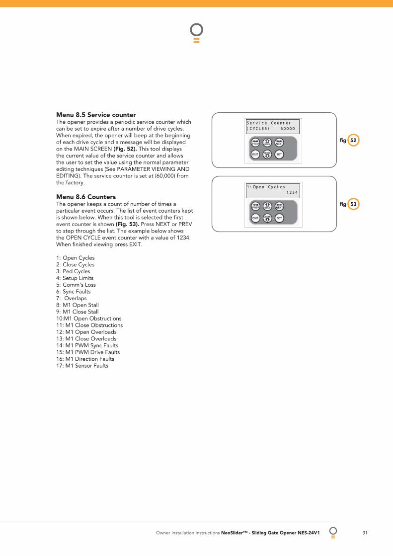
Menu 8.5 Service counter The opener provides a periodic service counter which can be set to expire after a number of drive cycles.When expired, the opener will beep at the beginning of each drive cycle and a message will be displayed on the MAIN SCREEN (Fig. 52). This tool displays the current value of the service counter and allows the user to set the value using the normal parameter editing techniques (See PARAMETER VIEWING AND EDITING). The service counter is set at (60,000) from the factory.
Menu 8.6 Counters The opener keeps a count of number of times a particular event occurs. The list of event counters kept is shown below. When this tool is selected the fi rst event counter is shown (Fig. 53). Press NEXT or PREV to step through the list. The example below shows the OPEN CYCLE event counter with a value of 1234. When fi nished viewing press EXIT.
1: Open Cycles2: Close Cycles3: Ped Cycles4: Setup Limits5: Comm’s Loss6: Sync Faults7: Overlaps8: M1 Open Stall9: M1 Close Stall10:M1 Open Obstructions11: M1 Close Obstructions12: M1 Open Overloads13: M1 Close Overloads14: M1 PWM Sync Faults15: M1 PWM Drive Faults16: M1 Direction Faults17: M1 Sensor Faults
32 NeoSlider™ - Sliding Gate Opener NES-24V1 Owner Installation Instructions
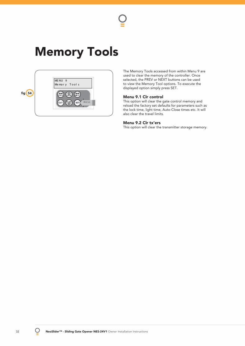
The Memory Tools accessed from within Menu 9 are used to clear the memory of the controller. Once selected, the PREV or NEXT buttons can be used to view the Memory Tool options. To execute the displayed option simply press SET.
Menu 9.1 Clr control This option will clear the gate control memory and reload the factory set defaults for parameters such as the lock time, light time, Auto-Close times etc. It will also clear the travel limits.
Menu 9.2 Clr tx’ers This option will clear the transmitter storage memory.
Memory Tools
54fi g
Owner Installation Instructions NeoSlider™ - Sliding Gate Opener NES-24V1 33
RED
BLACK
RED
BLACK
RED
BLACK
YELLOW
R1=5.6K OHM GREEN,BLUE,RED,GOLD.25WATT 5% TOLERENCERESISTANCE
R1
YELLOWBLACK
V- IN V+P.E BEAM
57fi g
57fi g
56fi g
+ - + - + -
24VDCOUT
LIGHTRELAY
LOCKRELAY
V+ IN V-P E BEAMS C
OM
OPN
STP
CLS OSC
SWP
PED
LIGHT RELAY MODULE
PULSE LOCK
COM
NO
LIGHT RELAY MODULE
POWER SUPPLY
NO
COM
ENG
AG
ED
3+ - + - + -
24VDCOUT
LIGHTRELAY
LOCKRELAY
V+ IN V-P E BEAMS C
OM
OPN
STP
CLS OSC
SWP
PED
55fi g
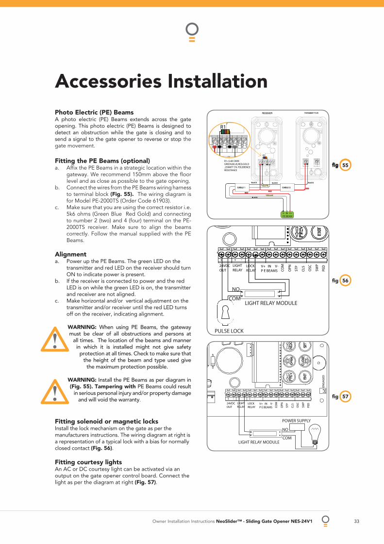
Accessories Installation Photo Electric (PE) BeamsA photo electric (PE) Beams extends across the gate opening. This photo electric (PE) Beams is designed to detect an obstruction while the gate is closing and to send a signal to the gate opener to reverse or stop the gate movement.
Fitting the PE Beams (optional)Affi x the PE Beams in a strategic location within the gateway. We recommend 150mm above the fl oor level and as close as possible to the gate opening. Connect the wires from the PE Beams wiring harness to terminal block (Fig. 55). The wiring diagram is for Model PE-2000TS (Order Code 61903).Make sure that you are using the correct resistor i.e. 5k6 ohms (Green Blue Red Gold) and connecting to number 2 (two) and 4 (four) terminal on the PE-2000TS receiver. Make sure to align the beams correctly. Follow the manual supplied with the PE Beams.
AlignmentPower up the PE Beams. The green LED on the transmitter and red LED on the receiver should turn ON to indicate power is present.If the receiver is connected to power and the red LED is on while the green LED is on, the transmitter and receiver are not aligned.Make horizontal and/or vertical adjustment on the transmitter and/or receiver until the red LED turns off on the receiver, indicating alignment.
WARNING: When using PE Beams, the gateway must be clear of all obstructions and persons at
all times. The location of the beams and manner in which it is installed might not give safety
protection at all times. Check to make sure that the height of the beam and type used give
the maximum protection possible.
WARNING: Install the PE Beams as per diagram in (Fig. 55). Tampering with PE Beams could result
in serious personal injury and/or property damage and will void the warranty.
Fitting solenoid or magnetic locks Install the lock mechanism on the gate as per the manufacturers instructions. The wiring diagram at right is a representation of a typical lock with a bias for normally closed contact (Fig. 56).
Fitting courtesy lights An AC or DC courtesy light can be activated via an output on the gate opener control board. Connect the light as per the diagram at right (Fig. 57).
a.
b.
c.
a.
b.
c.
R1
34 NeoSlider™ - Sliding Gate Opener NES-24V1 Owner Installation Instructions
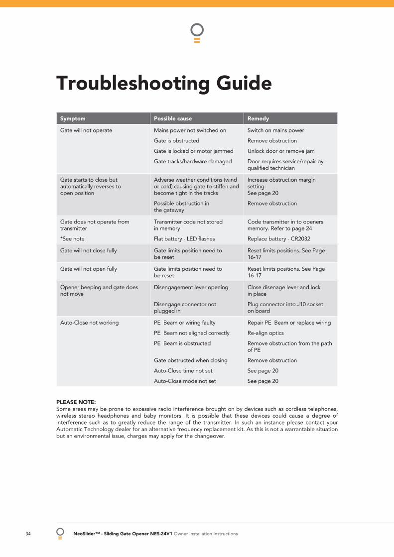
Symptom Possible cause Remedy
Gate will not operate Mains power not switched on
Gate is obstructed
Gate is locked or motor jammed
Gate tracks/hardware damaged
Switch on mains power
Remove obstruction
Unlock door or remove jam
Door requires service/repair by qualifi ed technician
Gate starts to close but automatically reverses to open position
Adverse weather conditions (wind or cold) causing gate to stiffen and become tight in the tracks
Possible obstruction in the gateway
Increase obstruction margin setting. See page 20
Remove obstruction
Gate does not operate from transmitter
*See note
Transmitter code not stored in memory
Flat battery - LED fl ashes
Code transmitter in to openers memory. Refer to page 24
Replace battery - CR2032
Gate will not close fully Gate limits position need to be reset
Reset limits positions. See Page 16-17
Gate will not open fully Gate limits position need to be reset
Reset limits positions. See Page 16-17
Opener beeping and gate does not move
Disengagement lever opening
Disengage connector not plugged in
Close disenage lever and lock in place
Plug connector into J10 socket on board
Auto-Close not working PE Beam or wiring faulty
PE Beam not aligned correctly
PE Beam is obstructed
Gate obstructed when closing
Auto-Close time not set
Auto-Close mode not set
Repair PE Beam or replace wiring
Re-align optics
Remove obstruction from the path of PE
Remove obstruction
See page 20
See page 20
PLEASE NOTE:Some areas may be prone to excessive radio interference brought on by devices such as cordless telephones, wireless stereo headphones and baby monitors. It is possible that these devices could cause a degree of interference such as to greatly reduce the range of the transmitter. In such an instance please contact your Automatic Technology dealer for an alternative frequency replacement kit. As this is not a warrantable situation but an environmental issue, charges may apply for the changeover.
Troubleshooting Guide
Owner Installation Instructions NeoSlider™ - Sliding Gate Opener NES-24V1 35
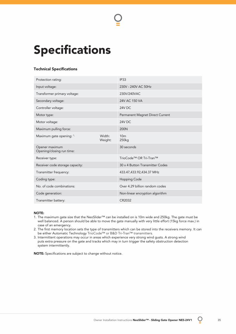
Specifi cationsTechnical Specifi cations
Protection rating: IP33
Input voltage: 230V - 240V AC 50Hz
Transformer primary voltage: 230V/240VAC
Secondary voltage: 24V AC 150 VA
Controller voltage: 24V DC
Motor type: Permanent Magnet Direct Current
Motor voltage: 24V DC
Maximum pulling force: 200N
Maximum gate opening: 1, Width: Weight:
10m250kg
Opener maximumOpening/closing run time:
30 seconds
Receiver type: TrioCode™ OR Tri-Tran™
Receiver code storage capacity: 30 x 4 Button Transmitter Codes
Transmitter frequency: 433.47,433.92,434.37 MHz
Coding type: Hopping Code
No. of code combinations: Over 4.29 billion random codes
Code generation: Non-linear encryption algorithm
Transmitter battery: CR2032
NOTE:1. The maximum gate size that the NeoSlider™ can be installed on is 10m wide and 250kg. The gate must be
well balanced. A person should be able to move the gate manually with very little effort (15kg force max.) in case of an emergency.
2. The fi rst memory location sets the type of transmitters which can be stored into the receivers memory. It can be either Automatic Technology TrioCode™ or B&D Tri-Tran™ transmitters.
3. Intermittent operations may occur in areas which experience very strong wind gusts. A strong wind puts extra pressure on the gate and tracks which may in turn trigger the safety obstruction detection system intermittently.
NOTE: Specifi cations are subject to change without notice.
36 NeoSlider™ - Sliding Gate Opener NES-24V1 Owner Installation Instructions
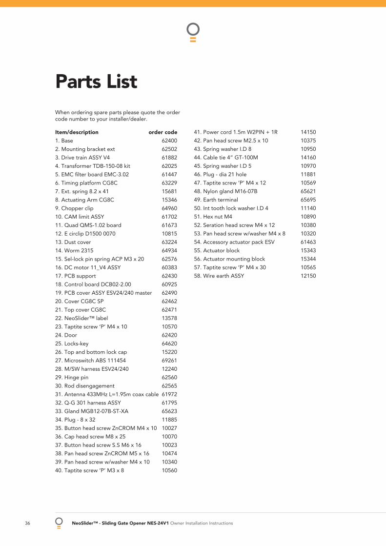
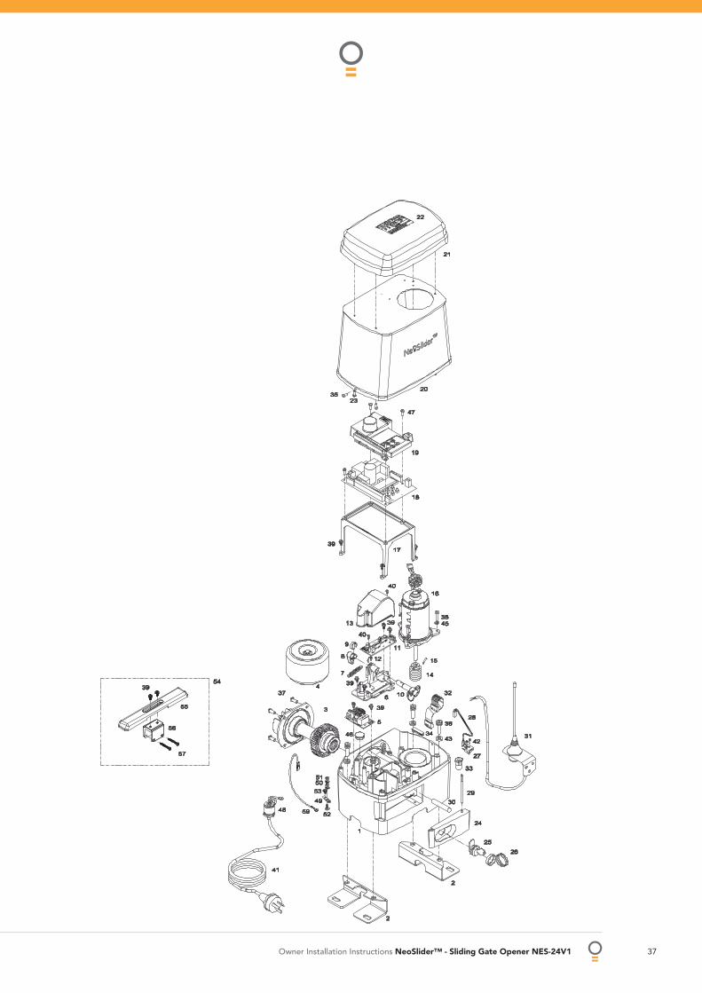
Parts ListWhen ordering spare parts please quote the order code number to your installer/dealer.
Item/description order code
1. Base 62400
2. Mounting bracket ext 62502
3. Drive train ASSY V4 61882
4. Transformer TDB-150-08 kit 62025
5. EMC fi lter board EMC-3.02 61447
6. Timing platform CG8C 63229
7. Ext. spring 8.2 x 41 15681
8. Actuating Arm CG8C 15346
9. Chopper clip 64960
10. CAM limit ASSY 61702
11. Quad QMS-1.02 board 61673
12. E circlip D1500 0070 10815
13. Dust cover 63224
14. Worm 2315 64934
15. Sel-lock pin spring ACP M3 x 20 62576
16. DC motor 11_V4 ASSY 60383
17. PCB support 62430
18. Control board DCB02-2.00 60925
19. PCB cover ASSY ESV24/240 master 62490
20. Cover CG8C SP 62462
21. Top cover CG8C 62471
22. NeoSlider™ label 13578
23. Taptite screw ‘P’ M4 x 10 10570
24. Door 62420
25. Locks-key 64620
26. Top and bottom lock cap 15220
27. Microswitch ABS 111454 69261
28. M/SW harness ESV24/240 12240
29. Hinge pin 62560
30. Rod disengagement 62565
31. Antenna 433MHz L=1.95m coax cable 61972
32. Q-G 301 harness ASSY 61795
33. Gland MGB12-07B-ST-XA 65623
34. Plug - 8 x 32 11885
35. Button head screw ZnCROM M4 x 10 10027
36. Cap head screw M8 x 25 10070
37. Button head screw S.S M6 x 16 10023
38. Pan head screw ZnCROM M5 x 16 10474
39. Pan head screw w/washer M4 x 10 10340
40. Taptite screw ‘P’ M3 x 8 10560
41. Power cord 1.5m W2PIN + 1R 14150
42. Pan head screw M2.5 x 10 10375
43. Spring washer I.D 8 10950
44. Cable tie 4” GT-100M 14160
45. Spring washer I.D 5 10970
46. Plug - dia 21 hole 11881
47. Taptite screw ‘P’ M4 x 12 10569
48. Nylon gland M16-07B 65621
49. Earth terminal 65695
50. Int tooth lock washer I.D 4 11140
51. Hex nut M4 10890
52. Seration head screw M4 x 12 10380
53. Pan head screw w/washer M4 x 8 10320
54. Accessory actuator pack ESV 61463
55. Actuator block 15343
56. Actuator mounting block 15344
57. Taptite screw ‘P’ M4 x 30 10565
58. Wire earth ASSY 12150
Owner Installation Instructions NeoSlider™ - Sliding Gate Opener NES-24V1 37
38 NeoSlider™ - Sliding Gate Opener NES-24V1 Owner Installation Instructions
Warranty1. This warranty is an addition to any non-excludable conditions or warranties that are implied into this contract
by relevant statute,including the Trade Practices Act 1974 (Cth).2. Subject to all of the matters set out below, Automatic Technology Australia Pty Ltd (“ATA”) warrants:
(a) swing and sliding gate opener drive units for twelve (12) months or 2500 cycles, whichever occurs fi rst;(b) all components and accessories for twelve (12) months, from the date of purchase (specifi ed in the sales docket receipt) as free of any defects in material and workmanship.
3. This warranty applies only where the purchaser: (a) immediately notifi es ATA or the retailer of the alleged defect;
(b) returns the product to the retailer; and(c) presents the relevant sales docket and this warranty document to the retailer to confi rm the date of purchase.
4. Except for this warranty, ATA gives no warranties of any kind whatsoever (whether express or implied), in relation to the product and all warranties of whatsoever kind relating to the product are, to the extent permissible by statute, hereby excluded.
5. To the extent permissible by statute, ATA disclaims any liability of whatsoever nature in respect of any claim or demand for loss or damage which arises out of: a) accidental damage to or normal wear and tear to the product or to the product’s components;
b) any cost relating to damage resulting from wear and tear;c) blown fuses, loss or damage caused by electrical surges, power surges or power spikes;d) loss or damage due to theft, fi re, fl ood, rain, water, lightning, storms or any other acts of God;e) maximum continuous operating time exceeding one (1) minute in ten (10);f) maximum operating force exceeding 15kg (150N) when moving the door or gate manually to the open or closed position;g) residential gate weight exceeding 250kg;h) gate not in safe and correct working order and condition;i) evidence of unauthorised repairs;j) any cost relating to damage caused by misuse, negligence or failure to maintain the equipment in a proper working order as per clauses (d) through (i);k) installation, adjustment or use which is not in accordance with the instructions set out in installation instruction manual;l) attempted or complete modifi cation or repairs to the product carried out by a person who is not authorised or has not been trained by ATA to carry out such modifi cation or repairs;m) faulty or unsuitable wiring of structure to which the product is fi xed or connected;n) radio (including citizen band transmission) or any electrical interference;o) damage caused by insects;p) loss or damage to any property whatsoever or any loss or expense whatsoever resulting or arising there from or any consequential loss;q) any cost or expense arising due to manufacturer recall of any product;r) any cost or expense due to negligence of the approved service provider;s) installation of a residential gate opener in a commercial or industrial situation or a non-single residential dwelling.
6. ATA’s liability under this warranty is limited, at ATA’s absolute option, to replacing or repairing the product which ATA, in its unfettered opinion, considers to be defective either in material and/or workmanship or to credit the dealer with the price at which the product was purchased by the dealer.
7. This warranty does not extend to cover labour for installation.8. This warranty is limited to Return-to-Base (RTB) repair and does not cover labour for on-site attendance.9. This warranty is void if the Product is not returned to the manufacturer in original or suitably secure packaging.10.This warranty is only applicable for repairs to the product carried out within Australia.11. This warranty does not cover consumable items including globes, batteries and fuses.12. This warranty is not transferable.13. Where the Product is retailed by any person other than ATA, except for the warranty set out above, such
person has no authority from ATA to give any warranty or guarantee on ATA’s behalf in addition to the warranty set out above.
NOTES:1. One (1) cycle = one (1) open and one (1) close action of the door or gate.2. This warranty is to be read in conjunction with the owner’s copy of the installation instruction manual.
Owner Installation Instructions NeoSlider™ - Sliding Gate Opener NES-24V1 39
Purchased from: Phone:
Installed by: Date:
Serial No:
Notes And Record

GARAGE DOOR OPENERS | GATE OPENERS | REMOTE CONTROL ACCESS SOLUTIONS
© August 2009 Automatic Technology (Australia) Pty Ltd. All rights reserved. NeoSlider™ and TrioCode™ are the trademarks of Automatic Technology (Australia) Pty Ltd. Tri-Tran™ is a trademark of B&D Doors and openers. No part of this document may be reproduced without prior permission. In an ongoing commitment to product quality we reserve the right to change specifi cation without notice. E&OE.
Automatic Technololgy (Australia) Pty LtdABN 11 007 125 368
6-8 Fiveways BoulevardKeysborough, Victoria, 3173, Australia
P 1300 133 944
+61 2 9722 5666 (International Enquiries Only)
www.ata-aust.com.au