Embed Size (px)
Citation preview
16025861 1 December 2004 ©2004 Maytag Services
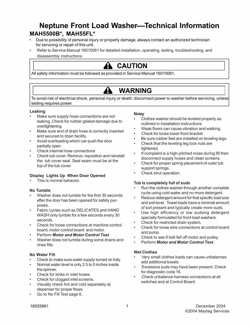
Neptune Front Load Washer⎯⎯⎯⎯⎯Technical InformationMAH5500B*, MAH55FL*• Due to possibility of personal injury or property damage, always contact an authorized technician
for servicing or repair of this unit.• Refer to Service Manual 16010061 for detailed installation, operating, testing, troubleshooting, and
disassembly instructions.
All safety information must be followed as provided in Service Manual 16010061.
To avoid risk of electrical shock, personal injury or death; disconnect power to washer before servicing, unless testing requires power.
CAUTION!
! WARNING
Leaking• Make sure supply hose connections are not
leaking. Check for rubber gasket damage due toovertightening.
• Make sure end of drain hose is correctly insertedand secured to drain facility.
• Avoid overloading which can push the doorpartially open.
• Check internal hose connections• Check tub cover. Remove, reposition and reinstall
the tub cover seal. Seal seam must be at thetop of the tub cover.
Display Lights Up When Door Opened• This is normal behavior.
No Tumble• Washer does not tumble for the first 30 seconds
after the door has been opened for safety pur-poses.
• Fabric cycles such as DELICATES and HANDWASH only tumble for a few seconds every 30seconds.
• Check for loose connections at machine controlboard, motor control board and motor.
• Perform Motor and Motor Control Test.• Washer does not tumble during some drains and
rinse fills.
No Water Fill• Check to make sure water supply turned on fully.• Normal water level is only 2.5 to 5 inches inside
the spinner.• Check for kinks in inlet hoses.• Check for clogged inlet screens.• Visually check hot and cold separately at
dispenser for proper flows.• Go to No Fill Test page 6.
Noisy• Clothes washer should be leveled properly as
outlined in installation instructions.• Weak floors can cause vibration and walking.• Check for loose lower front bracket• Be sure rubber feet are installed on leveling legs.• Check that the leveling leg lock nuts are
tightened.• If complaint is a high-pitched noise during fill then
disconnect supply hoses and clean screens.• Check for proper spring placement of outer tub
support springs.• Check strut operation.
Tub is completely full of suds• Run the clothes washer through another complete
cycle using cold water and no more detergent.• Reduce detergent amount for that specific load size
and soil level. Towel loads have a minimal amountof soil present and typically create more suds.
• Use high efficiency or low sudsing detergentspecially formulated for front load washers.
• Check for restricted drain system.• Check for loose wire connections at control board
and pump.• Check to see if belt fell off motor and pulley.• Perform Motor and Motor Control Test.
Wet Clothes• Very small clothes loads can cause unbalances
add additional towels.• Excessive suds may have been present. Check
for diagnostic code 16.• Check unbalance harness connections at all
switches and at Control Board.
.
December 2004 2 16025861©2004 Maytag Services
• Check for restricted drain system.• Perform Motor and Motor Control Test.
Will Not Lock• Door not all the way closed.• Check electrical connections at lock assembly and
machine control board. Go to Door Lock Test.
Will Not Unlock• Unplug and reconnect the power cord and wait 2
minutes to see if machine unlocks.• Check for door locked switch circuit to be closed
at machine control. (See board input/output chart)• Check to make sure belt has not fallen off.• Check for loose electrical connections at door lock
and at machine control board.• Perform Motor and Motor Control Test.
Will Not Start• Plug cord into live electrical outlet.• Check fuse or reset circuit breaker.• Push the START/PAUSE button to start the clothes
washer.• Close door and push the START/PAUSE button to
start the clothes washer. START/PAUSE LEDshould change from flashing to on continuously.
• Check to see if the washer is in a pause or soakperiod in the cycle. Wait briefly and it may start.
• Check for restricted drain system.
Will Not Drain• Check for restricted drain system.• Check low and high water levels. Go to No Fill test• Check for 120 VAC at the pump when a spin cycle
is selected.
Wrong Water Temperature• Too Hot/Too Cold; since this product uses a low
amount of water, the board regulates the incom-ing flow to temper the actual temperature of thewater in the tub. This may appear to besignificantly warmer/cooler than expected.
• Are both faucets on fully?• Make sure temperature selection is correct.• Make sure hoses are connected to correct
faucets and inlet connections. Flush water linebefore filling washer.
• Check the water heater. It should be set todeliver a minimum 120°F (49°C) hot water at thetap. Also check water heater capacity andrecovery rate.
• If the water heater is located a long distance fromwasher, water line may need to be purged prior tostarting wash cycle.
• Disconnect inlet hoses and clean screens.• This washer can sense if the fill hoses have been
reversed between hot and cold. If the fill hoses onthe washer were previously installed incorrectlyand then corrected, the washer will need to berun through a Hot / Cold cycle. If not resolved,check for proper resistance on the water valvethermistor. (See board input/output chart)
Codes Displayed On ConsoleIf owner observes codes on display, see tablebelow.
Sd = Suds: Machine has detected high level ofsuds. The machine will alter its cycle forthis situation. Use an HE detergent or cutdown on the amount of detergent slightly.This can be more likely on towel loads,consider HE detergent especially for theseloads.
do = Door is Open: The door of the machine isopen. Please make sure door is fully closedbefore starting cycle.
Continued on next page..........
! WARNINGTo avoid risk of electrical shock, personal injury, or death, disconnect power to washer before servicing,unless testing requires it.
Troubleshooting
16025861 3 December 2004 ©2004 Maytag Services
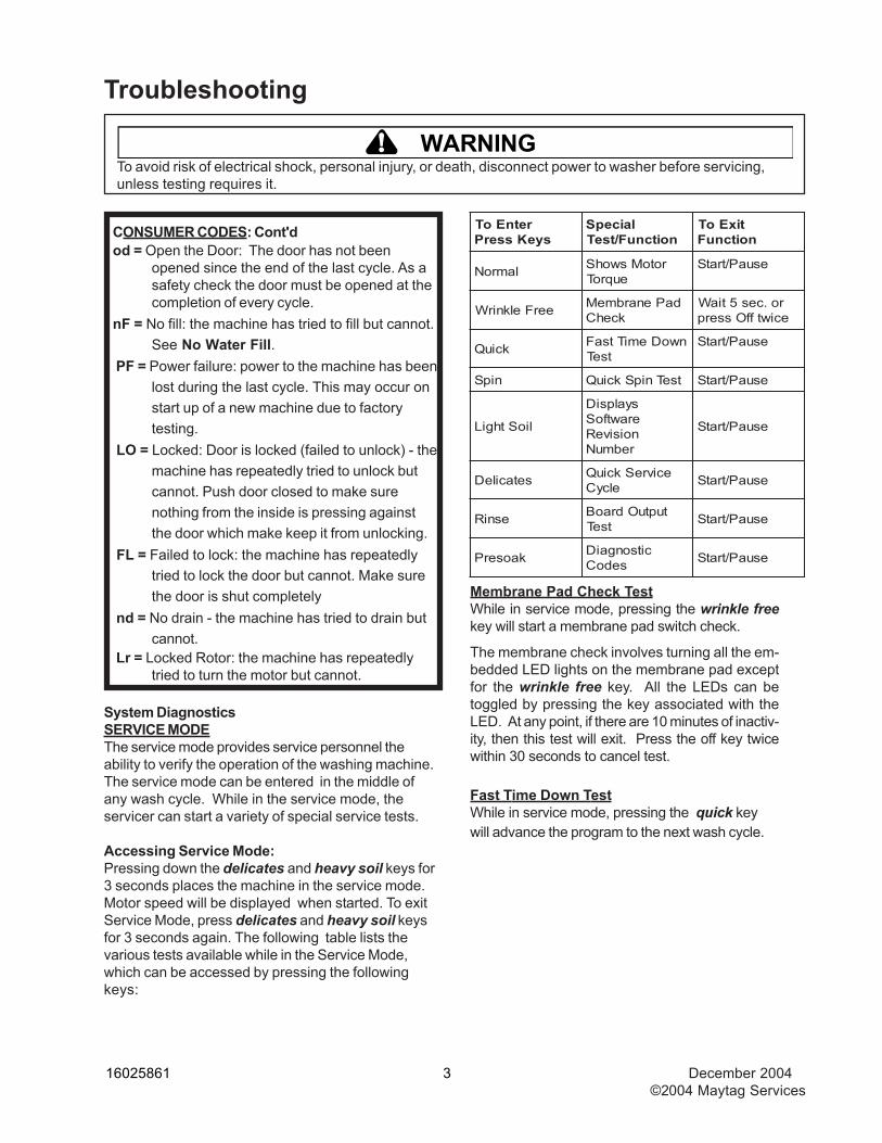
System DiagnosticsSERVICE MODEThe service mode provides service personnel theability to verify the operation of the washing machine.The service mode can be entered in the middle ofany wash cycle. While in the service mode, theservicer can start a variety of special service tests.
Accessing Service Mode:Pressing down the delicates and heavy soil keys for3 seconds places the machine in the service mode.Motor speed will be displayed when started. To exitService Mode, press delicates and heavy soil keysfor 3 seconds again. The following table lists thevarious tests available while in the Service Mode,which can be accessed by pressing the followingkeys:
Membrane Pad Check TestWhile in service mode, pressing the wrinkle freekey will start a membrane pad switch check.
The membrane check involves turning all the em-bedded LED lights on the membrane pad exceptfor the wrinkle free key. All the LEDs can betoggled by pressing the key associated with theLED. At any point, if there are 10 minutes of inactiv-ity, then this test will exit. Press the off key twicewithin 30 seconds to cancel test.
Fast Time Down TestWhile in service mode, pressing the quick keywill advance the program to the next wash cycle.
CONSUMER CODES: Cont'dod = Open the Door: The door has not been
opened since the end of the last cycle. As asafety check the door must be opened at thecompletion of every cycle.
nF = No fill: the machine has tried to fill but cannot.See No Water Fill.
PF = Power failure: power to the machine has beenlost during the last cycle. This may occur onstart up of a new machine due to factorytesting.
LO = Locked: Door is locked (failed to unlock) - themachine has repeatedly tried to unlock butcannot. Push door closed to make surenothing from the inside is pressing againstthe door which make keep it from unlocking.
FL = Failed to lock: the machine has repeatedlytried to lock the door but cannot. Make surethe door is shut completely
nd = No drain - the machine has tried to drain butcannot.
Lr = Locked Rotor: the machine has repeatedlytried to turn the motor but cannot.
retnEoTsyeKsserP
laicepSnoitcnuF/tseT
tixEoTnoitcnuF
lamroN rotoMswohSeuqroT
esuaP/tratS
eerFelknirW daPenarbmeMkcehC
ro.ces5tiaWeciwtffOsserp
kciuQ nwoDemiTtsaFtseT
esuaP/tratS
nipS tseTnipSkciuQ esuaP/tratS
lioSthgiL
syalpsiDerawtfoSnoisiveRrebmuN
esuaP/tratS
setacileD ecivreSkciuQelcyC esuaP/tratS
esniR tuptuOdraoBtseT esuaP/tratS
kaoserP citsongaiDsedoC esuaP/tratS
! WARNINGTo avoid risk of electrical shock, personal injury, or death, disconnect power to washer before servicing,unless testing requires it.
Troubleshooting
December 2004 4 16025861©2004 Maytag Services
foegatSelcyChsaW
oTsecnavdA
kaoserP kaoserPfodnE
hsaW fosetuniM5yrevEemiThsaW
niarD/nipS ehTfopetSyrevEeliforPnipS
esniR esniRfodnE
egnaRdeepS deyalpsiD
mpr99-0)a )lautca(99-0
mpr999-001)b 01/deepS
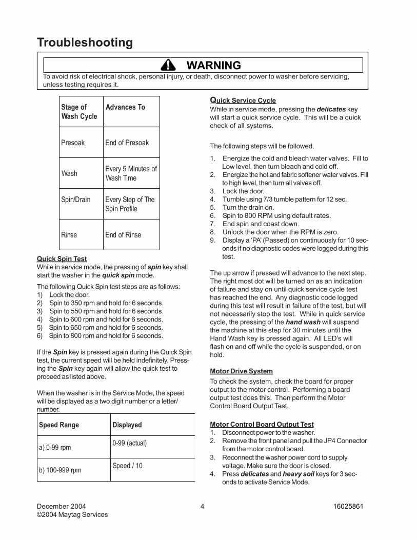
Quick Service CycleWhile in service mode, pressing the delicates keywill start a quick service cycle. This will be a quickcheck of all systems.
The following steps will be followed.
1. Energize the cold and bleach water valves. Fill toLow level, then turn bleach and cold off.
2. Energize the hot and fabric softener water valves. Fillto high level, then turn all valves off.
3. Lock the door.4. Tumble using 7/3 tumble pattern for 12 sec.5. Turn the drain on.6. Spin to 800 RPM using default rates.7. End spin and coast down.8. Unlock the door when the RPM is zero.9. Display a ‘PA’ (Passed) on continuously for 10 sec-
onds if no diagnostic codes were logged during thistest.
The up arrow if pressed will advance to the next step.The right most dot will be turned on as an indicationof failure and stay on until quick service cycle testhas reached the end. Any diagnostic code loggedduring this test will result in failure of the test, but willnot necessarily stop the test. While in quick servicecycle, the pressing of the hand wash will suspendthe machine at this step for 30 minutes until theHand Wash key is pressed again. All LED’s willflash on and off while the cycle is suspended, or onhold.
Motor Drive SystemTo check the system, check the board for properoutput to the motor control. Performing a boardoutput test does this. Then perform the MotorControl Board Output Test.
Motor Control Board Output Test1. Disconnect power to the washer.2. Remove the front panel and pull the JP4 Connector
from the motor control board.
The following Quick Spin test steps are as follows:1) Lock the door.2) Spin to 350 rpm and hold for 6 seconds.3) Spin to 550 rpm and hold for 6 seconds.4) Spin to 600 rpm and hold for 6 seconds.5) Spin to 650 rpm and hold for 6 seconds.6) Spin to 800 rpm and hold for 6 seconds.
If the Spin key is pressed again during the Quick Spintest, the current speed will be held indefinitely. Press-ing the Spin key again will allow the quick test toproceed as listed above.
When the washer is in the Service Mode, the speedwill be displayed as a two digit number or a letter/number.
Quick Spin TestWhile in service mode, the pressing of spin key shallstart the washer in the quick spin mode.
3. Reconnect the washer power cord to supplyvoltage. Make sure the door is closed.
4. Press delicates and heavy soil keys for 3 sec-onds to activate Service Mode.
! WARNINGTo avoid risk of electrical shock, personal injury, or death, disconnect power to washer before servicing,unless testing requires it.
Troubleshooting
16025861 5 December 2004 ©2004 Maytag Services
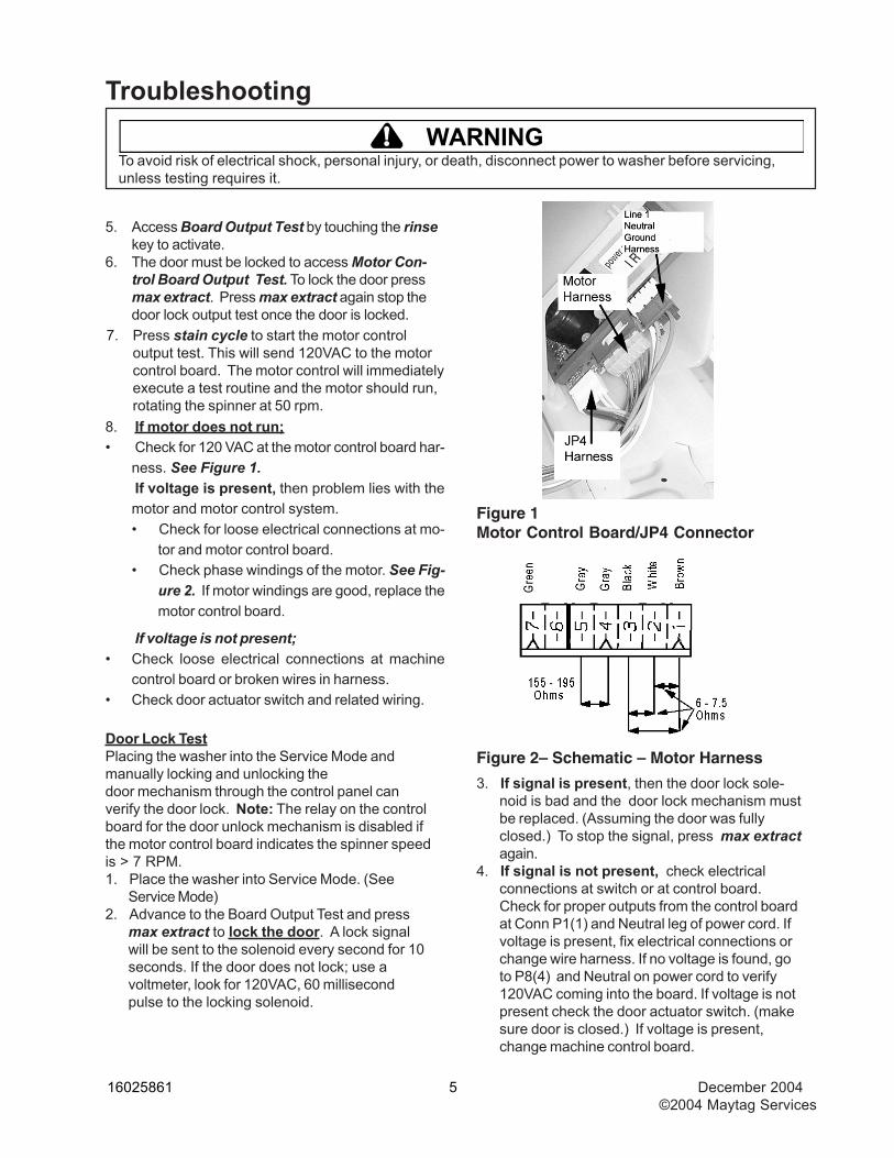
Figure 1Motor Control Board/JP4 Connector
Figure 2– Schematic – Motor Harness
8. If motor does not run;• Check for 120 VAC at the motor control board har-
ness. See Figure 1.If voltage is present, then problem lies with themotor and motor control system.• Check for loose electrical connections at mo-
tor and motor control board.• Check phase windings of the motor. See Fig-
ure 2. If motor windings are good, replace themotor control board.
If voltage is not present;• Check loose electrical connections at machine
control board or broken wires in harness.• Check door actuator switch and related wiring.
Door Lock TestPlacing the washer into the Service Mode andmanually locking and unlocking thedoor mechanism through the control panel canverify the door lock. Note: The relay on the controlboard for the door unlock mechanism is disabled ifthe motor control board indicates the spinner speedis > 7 RPM.1. Place the washer into Service Mode. (See
Service Mode)2. Advance to the Board Output Test and press
max extract to lock the door. A lock signalwill be sent to the solenoid every second for 10seconds. If the door does not lock; use avoltmeter, look for 120VAC, 60 millisecondpulse to the locking solenoid.
7. Press stain cycle to start the motor controloutput test. This will send 120VAC to the motorcontrol board. The motor control will immediatelyexecute a test routine and the motor should run,rotating the spinner at 50 rpm.
3. If signal is present, then the door lock sole-noid is bad and the door lock mechanism mustbe replaced. (Assuming the door was fullyclosed.) To stop the signal, press max extractagain.
4. If signal is not present, check electricalconnections at switch or at control board.Check for proper outputs from the control boardat Conn P1(1) and Neutral leg of power cord. Ifvoltage is present, fix electrical connections orchange wire harness. If no voltage is found, goto P8(4) and Neutral on power cord to verify120VAC coming into the board. If voltage is notpresent check the door actuator switch. (makesure door is closed.) If voltage is present,change machine control board.
5. Access Board Output Test by touching the rinsekey to activate.
6. The door must be locked to access Motor Con-trol Board Output Test. To lock the door pressmax extract. Press max extract again stop thedoor lock output test once the door is locked.
! WARNINGTo avoid risk of electrical shock, personal injury, or death, disconnect power to washer before servicing,unless testing requires it.
Troubleshooting
December 2004 6 16025861©2004 Maytag Services
5. Advance to the Board Output Test and pressextra rinse to unlock the door. An unlocksignal will be sent to the solenoid every secondfor 10 seconds.If the door does not lock, use a voltmeter, lookfor 120VAC, 60 millisecond pulse to the lockingsolenoid.If signal is present, then the door lock sole-noid is bad and the door lock mechanism mustbe replaced. To stop the signal, press extrarinse again.If signal is not present, check electricalconnections at switch or at control board.Check for proper outputs from the control boardat Conn P8(3) and Neutral leg of power cord. Ifvoltage is present, fix electrical connections orchange wire harness. If no voltage is found, goto P8(4) and Neutral on power cord to verify120VAC coming into the board. If voltage is notpresent check the door actuator switch. (makesure door is closed.) If voltage is present,change machine control board.
No Fill Test1. Close the door and start a spin cycle to drain all
water from the washer to reset the pressure switch.2. Press Off and open door to verify all water is re-
moved from the washer. If water still present, goto Will Not Drain diagnostics.
3. If water is drained out, close the door and go toService Mode, press delicates and heavy soilskeys for 3 seconds. If it is likely to need access tothe water valve for voltage checks, consider raisingthe top cover now and close the door so that thefollowing steps will not need to be repeated.
4. While in service mode, press the hand wash keyplaces the washer into the Board Input test.
5. Check the lower water level by pressing the handwash key.
6. "_1" indicates the washer is full. If full, check thelower water level input at the machine control boardby reading DC voltage between P4(4) and P4(8).
If voltage is present at the machine control board,check voltage at pressure switch between BU andBR . If voltage present at pressure switch, re-place pressure switch. If voltage is not present atpressure switch, check or replace harness. If novoltage is present at the Machine control board,replace the machine control board.
7. "_0" indicates the washer is empty: If empty,press the wrinkle free key to check the high wa-ter level.
8. "--1" indicates full. If full, check the high water level input at the machine control board byreading 120 VAC voltage between P1(4) andNeutral P6(2). If120 VAC is not present at themachine control board, check continuity atpressure switch across GY and YL. If nocontinuity, replace pressure switch. If continuity,check door switch and harness to pressure switchand harness from pressure switch to Machinecontrol board. If 120 VAC is present at theMachine control board, replace the machinecontrol board.
9. "--0" indicates empty. If empty, exit board inputtest mode by pressing the start/pause key. Thenenter board output test mode by pressing the rinsekey.
10. Turn the cold water valve on by pressing the wrinklefree key. Check for cold water flow at the dispenser.If no cold water flow, check the cold water valve for120 VAC between BU and WH. If 120 VAC ispresent at the cold valve, replace the water valve. If120 VAC is not present at the cold valve, check for120 VAC at the machine control board betweenP1(3) and Neutral. If 120 VAC is present at themachine control board, check or replace theharness. If 120 VAC is not present at the machinecontrol board, replace the machine control board.If cold water flows, turn the cold valve off by pressingthe wrinkle free button.
! WARNINGTo avoid risk of electrical shock, personal injury, or death, disconnect power to washer before servicing,unless testing requires it.
Troubleshooting
16025861 7 December 2004 ©2004 Maytag Services
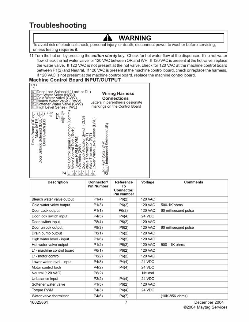
Description Connector/Pin Number
ReferenceTo
Connector/Pin Number
Voltage Comments
Bleach water valve output P1(4) P6(2) 120 VACCold water valve output P1(3) P6(2) 120 VAC 500-1K ohmsDoor Lock output P1(1) P6(2) 120 VAC 60 millisecond pulseDoor lock switch input P4(5) P4(4) 24 VDCDoor switch input P8(4) P6(2) 120 VACDoor unlock output P8(3) P6(2) 120 VAC 60 millisecond pulseDrain pump output P8(1) P6(2) 120 VACHigh water level - input P1(6) P6(2) 120 VACHot water valve output P1(2) P6(2) 120 VAC 500 - 1K ohmsL1- machine control board P6(1) P6(2) 120 VACL1- motor control P8(2) P6(2) 120 VACLower water level - input P4(8) P4(4) 24 VDCMotor control tach P4(2) P4(4) 24 VDCNeutral (120 VAC) P6(2) NeutralUnbalance input P3(2) P4(4) 24 VDCSoftener water valve P1(5) P6(2) 120 VACTorque PWM P4(3) P4(4) 24 VDCWater valve thermistor P4(6) P4(7) (10K-85K ohms)
Machine Control Board INPUT/OUTPUT
11.Turn the hot on by pressing the cotton sturdy key. Check for hot water flow at the dispenser. If no hot waterflow, check the hot water valve for 120 VAC between OR and WH. If 120 VAC is present at the hot valve, replacethe water valve. If 120 VAC is not present at the hot valve, check for 120 VAC at the machine control boardbetween P1(2) and Neutral. If 120 VAC is present at the machine control board, check or replace the harness.If 120 VAC is not present at the machine control board, replace the machine control board.
! WARNINGTo avoid risk of electrical shock, personal injury, or death, disconnect power to washer before servicing,unless testing requires it.
Troubleshooting
High Level Sense (HWL)Softener Water Valve (SWV)Bleach Water Valve ( BWV)Cold Water Valve (CWV)Hot Water Valve (HWV)Door Lock Solenoid ( Lock or DL)
Doo
r Sw
itch
(DS)
Doo
r Unl
ock
Sol
enoi
d (D
UL)
Mot
or (M
TR)
Dra
in P
ump
(DP) L1
N
Low
er W
ash
Leve
l Sen
se (L
WL)
Valv
e Th
erm
isto
r (W
T)Va
lve
Ther
mis
tor (
WT)
Doo
r Loc
k Ac
tuat
or S
witc
h (D
LS)
+24
Volts
(24V
)To
rque
PW
M (P
WM
)M
otor
Con
trol T
ach
(Tac
h)M
tr C
ontro
l Sig
nal C
omm
on (C
omm
)
P3
+24
Volts
(24V
)U
nbal
ance
d Sw
itche
s(U
B)
Wiring HarnessConnections
Letters in parenthesis designate markings on the Control Board
P4
December 2004 8 16025861©2004 Maytag Services
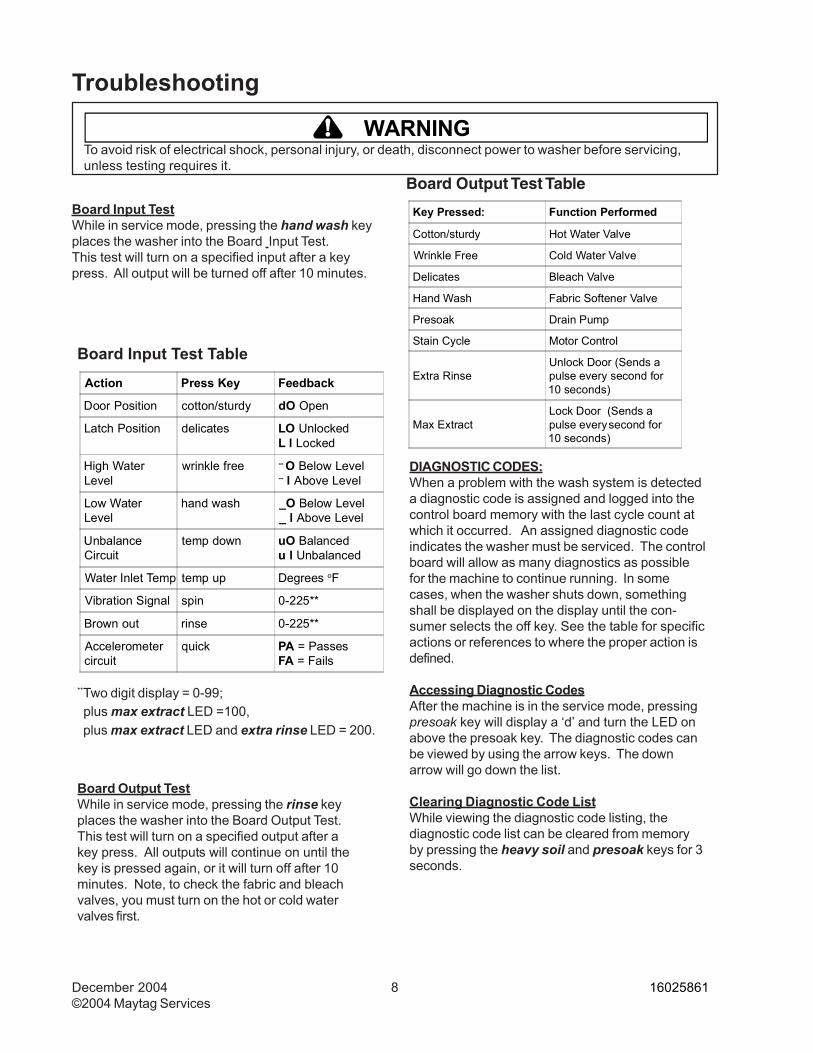
DIAGNOSTIC CODES:When a problem with the wash system is detecteda diagnostic code is assigned and logged into thecontrol board memory with the last cycle count atwhich it occurred. An assigned diagnostic codeindicates the washer must be serviced. The controlboard will allow as many diagnostics as possiblefor the machine to continue running. In somecases, when the washer shuts down, somethingshall be displayed on the display until the con-sumer selects the off key. See the table for specificactions or references to where the proper action isdefined.
Accessing Diagnostic CodesAfter the machine is in the service mode, pressingpresoak key will display a ‘d’ and turn the LED onabove the presoak key. The diagnostic codes canbe viewed by using the arrow keys. The downarrow will go down the list.
Clearing Diagnostic Code ListWhile viewing the diagnostic code listing, thediagnostic code list can be cleared from memoryby pressing the heavy soil and presoak keys for 3seconds.
Board Output Test Table
Key Pressed: Function Performed
Cotton/sturdy Hot Water Valve
Wrinkle Free Cold Water Valve
Delicates Bleach Valve
Hand Wash Fabric Softener Valve
Presoak Drain Pump
Stain Cycle Motor Control
Extra RinseUnlock Door (Sends apulse every second for10 seconds)
Max ExtractLock Door (Sends apulse every second for10 seconds)
Board Input TestWhile in service mode, pressing the hand wash keyplaces the washer into the Board Input Test.This test will turn on a specified input after a keypress. All output will be turned off after 10 minutes.
Board Output TestWhile in service mode, pressing the rinse keyplaces the washer into the Board Output Test.This test will turn on a specified output after akey press. All outputs will continue on until thekey is pressed again, or it will turn off after 10minutes. Note, to check the fabric and bleachvalves, you must turn on the hot or cold watervalves first.
**Two digit display = 0-99; plus max extract LED =100, plus max extract LED and extra rinse LED = 200.
Board Input Test Table
Action Press Key Feedback
Door Position cotton/sturdy dO Open
Latch Position delicates LO UnlockedL l Locked
High WaterLevel
wrinkle free -- O Below Level-- l Above Level
Low WaterLevel
hand wash _O Below Level_ l Above Level
UnbalanceCircuit
temp down uO Balancedu l Unbalanced
Water Inlet Temp temp up Degrees oF
Vibration Signal spin 0-225**
Brown out rinse 0-225**
Accelerometercircuit
quick PA = PassesFA = Fails
! WARNINGTo avoid risk of electrical shock, personal injury, or death, disconnect power to washer before servicing,unless testing requires it.
Troubleshooting
16025861 9 December 2004 ©2004 Maytag Services
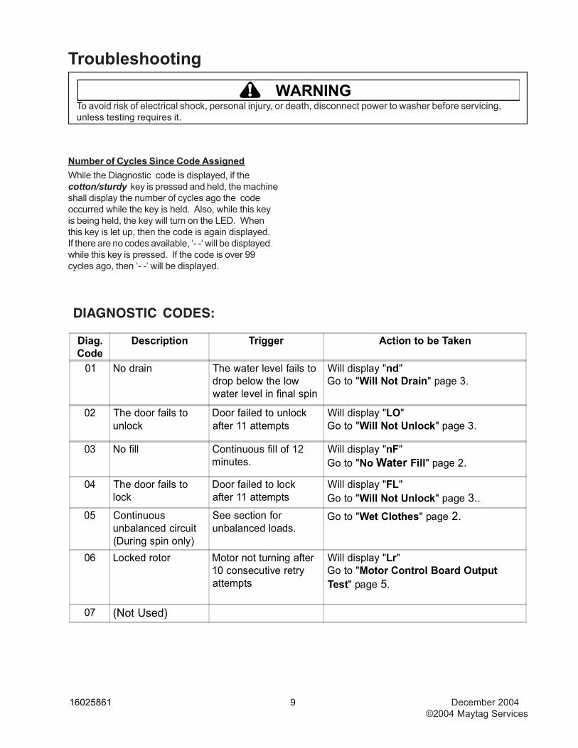
Diag.Code
Description Trigger Action to be Taken
01 No drain The water level fails todrop below the lowwater level in final spin
Will display "nd"Go to "Will Not Drain" page 3.
02 The door fails tounlock
Door failed to unlockafter 11 attempts
Will display "LO"Go to "Will Not Unlock" page 3.
03 No fill Continuous fill of 12minutes.
Will display "nF"Go to "No Water Fill" page 2.
04 The door fails tolock
Door failed to lockafter 11 attempts
Will display "FL"Go to "Will Not Unlock" page 3..
05 Continuousunbalanced circuit(During spin only)
See section forunbalanced loads.
Go to "Wet Clothes" page 2.
06 Locked rotor Motor not turning after10 consecutive retryattempts
Will display "Lr"Go to "Motor Control Board OutputTest" page 5.
07 (Not Used)
DIAGNOSTIC CODES:
Number of Cycles Since Code AssignedWhile the Diagnostic code is displayed, if thecotton/sturdy key is pressed and held, the machineshall display the number of cycles ago the codeoccurred while the key is held. Also, while this keyis being held, the key will turn on the LED. Whenthis key is let up, then the code is again displayed.If there are no codes available, ‘- -‘ will be displayedwhile this key is pressed. If the code is over 99cycles ago, then ‘- -‘ will be displayed.
! WARNINGTo avoid risk of electrical shock, personal injury, or death, disconnect power to washer before servicing,unless testing requires it.
Troubleshooting
December 2004 10 16025861©2004 Maytag Services
! WARNINGTo avoid risk of electrical shock, personal injury, or death, disconnect power to washer before servicing,unless testing requires it.
Troubleshooting
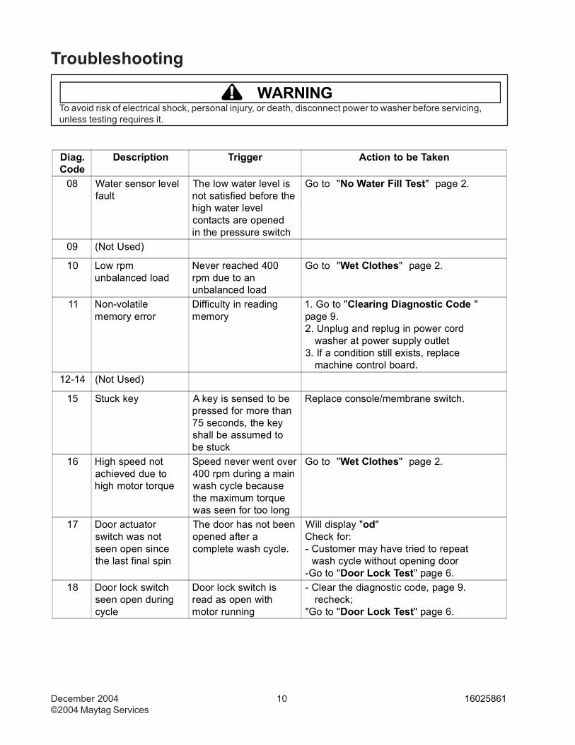
Diag.Code
Description Trigger Action to be Taken
08 Water sensor levelfault
The low water level isnot satisfied before thehigh water levelcontacts are openedin the pressure switch
Go to "No Water Fill Test" page 2.
09 (Not Used)
10 Low rpmunbalanced load
Never reached 400rpm due to anunbalanced load
Go to "Wet Clothes" page 2.
11 Non-volatilememory error
Difficulty in readingmemory
1. Go to "Clearing Diagnostic Code "page 9.2. Unplug and replug in power cord
washer at power supply outlet3. If a condition still exists, replace
machine control board.12-14 (Not Used)
15 Stuck key A key is sensed to bepressed for more than75 seconds, the keyshall be assumed tobe stuck
Replace console/membrane switch.
16 High speed notachieved due tohigh motor torque
Speed never went over400 rpm during a mainwash cycle becausethe maximum torquewas seen for too long
Go to "Wet Clothes" page 2.
17 Door actuatorswitch was notseen open sincethe last final spin
The door has not beenopened after acomplete wash cycle.
Will display "od"Check for:- Customer may have tried to repeat
wash cycle without opening door-Go to "Door Lock Test" page 6.
18 Door lock switchseen open duringcycle
Door lock switch isread as open withmotor running
- Clear the diagnostic code, page 9.recheck;
"Go to "Door Lock Test" page 6.
16025861 11 December 2004 ©2004 Maytag Services
! WARNINGTo avoid risk of electrical shock, personal injury, or death, disconnect power to washer before servicing,unless testing requires it.
Troubleshooting
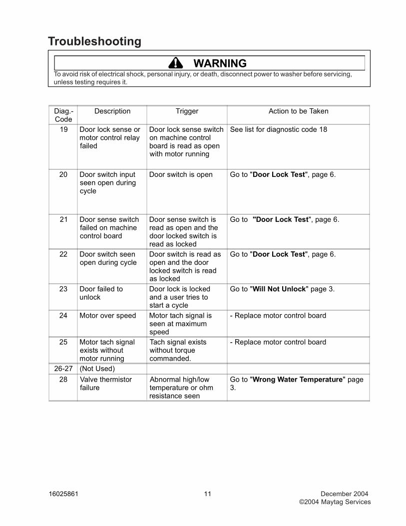
Diag.-Code
Description Trigger Action to be Taken
19 Door lock sense ormotor control relayfailed
Door lock sense switchon machine controlboard is read as openwith motor running
See list for diagnostic code 18
20 Door switch inputseen open duringcycle
Door switch is open Go to "Door Lock Test", page 6.
21 Door sense switchfailed on machinecontrol board
Door sense switch isread as open and thedoor locked switch isread as locked
Go to "Door Lock Test", page 6.
22 Door switch seenopen during cycle
Door switch is read asopen and the doorlocked switch is readas locked
Go to "Door Lock Test", page 6.
23 Door failed tounlock
Door lock is lockedand a user tries tostart a cycle
Go to "Will Not Unlock" page 3.
24 Motor over speed Motor tach signal isseen at maximumspeed
- Replace motor control board
25 Motor tach signalexists withoutmotor running
Tach signal existswithout torquecommanded.
- Replace motor control board
26-27 (Not Used)28 Valve thermistor
failureAbnormal high/lowtemperature or ohmresistance seen
Go to "Wrong Water Temperature" page3.
December 2004 12 16025861©2004 Maytag Services
! WARNINGTo avoid risk of electrical shock, personal injury, or death, disconnect power to washer before servicing,unless testing requires it.
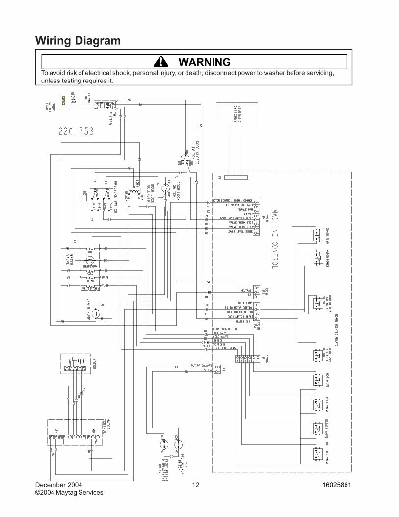
Wiring Diagram
16025861 13 December 2004 ©2004 Maytag Services
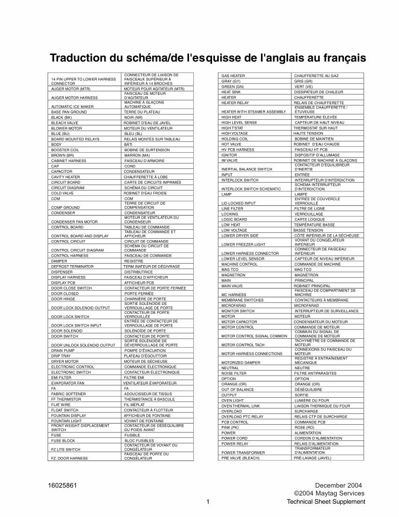
Traduction du schéma/de l'esquisse de l'anglais au français
©2004 Maytag Services Technical Sheet Supplement 1
14 PIN UPPER TO LOWER HARNESS CONNECTOR
CONNECTEUR DE LIAISON DE FAISCEAUX SUPÉRIEUR À INFÉRIEUR À 14 BROCHES
AUGER MOTOR (MTR) MOTEUR POUR AGITATEUR (MTR)
AUGER MOTOR HARNESS FAISCEAU DE MOTEUR D’AGITATEUR
AUTOMATIC ICE MAKER MACHINE À GLAÇONS AUTOMATIQUE
BASE PAN GROUND TERRE DU PLATEAU
BLACK (BK) NOIR (NR)
BLEACH VALVE ROBINET D’EAU DE JAVEL
BLOWER MOTOR MOTEUR DU VENTILATEUR BLUE (BU) BLEU (BL)
BOARD MOUNTED RELAYS RELAIS MONTÉS SUR TABLEAU BODY BÂTI
BOOSTER COIL BOBINE DE SURTENSION BROWN (BR) MARRON (MA)
CABINET HARNESS FAISCEAU D’ARMOIRE
CAP COND CAPACITOR CONDENSATEUR
CAVITY HEATER CHAUFFERETTE À LOBE CIRCUIT BOARD CARTE DE CIRCUITS IMPRIMÉS
CIRCUIT DIAGRAM SCHÉMA DU CIRCUIT COLD VALVE ROBINET D'EAU FROIDE
COM COM
COMP GROUND TERRE DE CIRCUIT DE COMPENSATION
CONDENSER CONDENSATEUR
CONDENSER FAN MOTOR MOTEUR DE VENTILATEUR DU CONDENSEUR
CONTROL BOARD TABLEAU DE COMMANDE
CONTROL BOARD AND DISPLAY TABLEAU DE COMMANDE ET AFFICHEUR
CONTROL CIRCUIT CIRCUIT DE COMMANDE
CONTROL CIRCUIT DIAGRAM SCHÉMA DU CIRCUIT DE COMMANDE
CONTROL HARNESS FAISCEAU DE COMMANDE
DAMPER REGISTRE
DEFROST TERMINATOR TERM INATEUR DE DÉGIVRAGE
DISPENSER DISTRIBUTRICE DISPLAY HARNESS FAISCEAU D’AFFICHEUR
DISPLAY PCB AFFICHEUR PCB DOOR CLOSE SWITCH CONTACTEUR DE PORTE FERMÉE
DOOR CLOSED PORTE FERMÉE DOOR HINGE CHARNIÈRE DE PORTE
DOOR LOCK SOLENOID OUTPUT SORTIE SOLÉNOÏDE DE VERROUILLAGE DE PORTE
DOOR LOCK SWITCH CONTACTEUR DE PORTE VERROUILLÉE
DOOR LOCK SWITCH INPUT ENTRÉE DE CONTACTEUR DE VERROUILLAGE DE PORTE
DOOR SOLENOID SOLÉNOÏDE DE PORTE
DOOR SWITCH CONTACTEUR DE PORTE
DOOR UNLOCK SOLENOID OUTPUT SORTIE SOLÉNOÏDE DE DÉVERROUILLAGE DE PORTE
DRAIN PUMP POMPE D’ÉVACUATION DRIP TRAY PLATEAU D’ÉGOUTTOIR
DRYER MOTOR MOTEUR DE SÉCHEUSE ELECTRONIC CONTROL COMMANDE ÉLECTRONIQUE
ELECTRONIC SWITCH CONTACTEUR ÉLECTRONIQUE EMI FILTER FILTRE EMI
EVAPORATOR FAN VENTILATEUR ÉVAPORATEUR FA FA
FABRIC SOFTENER ADOUCISSEUR DE TISSUS FF THERMISTOR THERMISTANCE À BASCULE
FLAT WIRE FIL MÉPLAT
FLOAT SWITCH CONTACTEUR À FLOTTEUR
FOUNTAIN DISPLAY AFFICHEUR DE FONTAINE FOUNTAIN LIGHT VOYANT DE FONTAINE FRONT WEIGHT DISPLACEMENT SWITCH
CONTACTEUR DE DÉSÉQUILIBRE DU POIDS AVANT
FUSE FUSIBLE
FUSE BLOCK BLOC FUSIBLES
FZ LITE SWITCH CONTACTEUR DE VOYANT DU CONGÉLATEUR
FZ. DOOR HARNESS FAISCEAU DE PORTE DU CONGÉLATEUR
GAS HEATER CHAUFFERETTE AU GAZ
GRAY (GY) GRIS (GR)
GREEN (GN) VERT (VE) HEAT SINK DISSIPATEUR DE CHALEUR
HEATER CHAUFFERETTE HEATER RELAY RELAIS DE CHAUFFERETTE
HEATER WITH STEAMER ASSEMBLY ENSEMBLE CHAUFFERETTE / ÉTUVEUSE
HIGH HEAT TEMPÉRATURE ÉLEVÉE HIGH LEVEL SENSE CAPTEUR DE HAUT NIVEAU
HIGH T'STAT THERMOSTAT SUR HAUT HIGH VOLTAGE HAUTE TENSION
HOLDING COIL BOBINE DE MAINTIEN HOT VALVE ROBINET D’EAU CHAUDE
HV PCB HARNESS FAISCEAU HT PCB
IGNITOR DISPOSITIF D’ALLUMAGE IM VALVE ROBINET DE MACHINE À GLAÇONS
INERTIAL BALANCE SWITCH CONTACTEUR D’ÉQUILIBREUR D’INERTIE
INPUT ENTRÉE
INTERLOCK SWITCH INTERRUPTEUR D’INTERDICTION
INTERLOCK SWITCH SCHEMATIC SCHEMA INTERRUPTEUR D’INTERDICTION
LAMP LAMPE
LID LOCKED INPUT ENTRÉE DE COUVERCLE VERROUILLÉ
LINE FILTER FILTRE DE LIGNE
LOCKING VERROUILLAGE LOGIC BOARD CARTE LOGIQUE
LOW HEAT TEMPÉRATURE BASSE
LOW VOLTAGE BASSE TENSION LOWER DRYER SIDE CÔTÉ INFÉRIEUR DE LA SÉCHEUSE
LOWER FREEZER LIGHT VOYANT DU CONGÉLATEUR INFÉRIEUR
LOWER HARNESS CONNECTOR CONNECTEUR DE FAISCEAU INFÉRIEUR
LOWER LEVEL SENSOR CAPTEUR DE NIVEAU INFÉRIEUR
MACHINE CONTROL COMMANDE DE MACHINE MAG TCO MAG TCO
MAGNETRON MAGNÉTRON
MAIN PRINCIPAL
MAIN VALVE ROBINET PRINCIPAL
MC HARNESS FAISCEAU DE COMPARTIMENT DE MACHINE
MEMBRANE SWITCHES CONTACTEURS À MEMBRANE
MICROFARAD MICROFARAD
MONITOR SWITCH INTERRUPTEUR DE SURVEILLANCE MOTOR MOTEUR
MOTOR CAPACITOR CONDENSATEUR DU MOTEUR MOTOR CONTROL COMMANDE DE MOTEUR
MOTOR CONTROL SIGNAL COMMON COMMUN DU SIGNAL DE COMMANDE DE MOTEUR
MOTOR CONTROL TACH TACHYMÈTRE DE COMMANDE DE MOTEUR
MOTOR HARNESS CONNECTIONS CONNEXIONS DU FAISCEAU DU MOTEUR
MOTORIZED DAMPER REGISTRE À ENTRAÎNEMENT MÉCANIQUE
NEUTRAL NEUTRE NOISE FILTER FILTRE ANTIPARASITES
OPTION OPTION ORANGE (OR) ORANGE (OR)
OUT OF BALANCE DÉSÉQUILIBRE
OUTPUT SORTIE
OVEN LIGHT LUMIÈRE DU FOUR
OVEN THERMAL LINK LIAISON THERMIQUE DU FOUR OVERLOAD SURCHARGE OVERLOAD PTC RELAY RELAIS CTP DE SURCHARGE
PCB CONTROL COMMANDE PCB PINK (PK) ROSE (RO)
POWER ALIMENTATION POWER CORD CORDON D’ALIMENTATION
POWER RELAY RELAIS D’ALIMENTATION
POWER TRANSFORMER TRANSFORMATEUR D’ALIMENTATION
PRE VALVE (BLEACH) PRÉ-LAVAGE (JAVEL)
December 2004 14 16025861©2004 Maytag Services
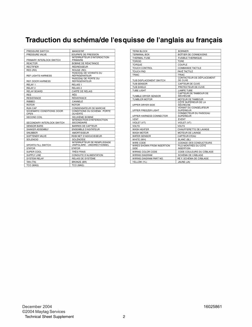
Traduction du schéma/de l'esquisse de l'anglais au français
Technical Sheet Supplement ©2004 Maytag Services 2
PRESSURE SWITCH MANOSTAT PRESSURE VALVE SOUPAPE DE PRESSION
PRIMARY INTERLOCK SWITCH INTERRUPTEUR D’INTERDICTION PRIMAIRE
REACTOR BOBINE DE RÉACTANCE
RECTIFIER REDRESSEUR RED (RD) ROUGE (RO)
REF LIGHTS HARNESS FAISCEAU DE VOYANTS DU RÉFRIGÉRATEUR
REF. DOOR HARNESS FAISCEAU DE PORTE DU RÉFRIGÉRATEUR
RELAY 1 RELAIS 1
RELAY 2 RELAIS 2 RELAY BOARD CARTE DE RELAIS
RES RÉS RESISTANCE RÉSISTANCE
RIBBED CANNELÉ ROTOR ROTOR
RUN CAP CONDENSATEUR DE MARCHE SCHEMATIC CONDITIONS: DOOR OPEN
CONDITIONS DU SCHÉMA : PORTE OUVERTE
SECOND COIL DEUXIÈME BOBINE
SECONDARY INTERLOCK SWITCH INTERDICTION D’INTERDICTION SECONDAIRE
SENSOR BARS BARRES DE CAPTEUR SHAKER ASSEMBLY ENSEMBLE D'AGITATEUR
SNUBBER AMORTISSEUR SOFTENER VALVE ROBI NET D’ADOUCISSEUR
SOLENOID SOLÉNOÏDE
SPORTS FILL SWITCH INTERRUPTEUR DE REMPLISSAGE UNIPOLAIRE - UNIDIRECTIONNEL
STATOR STATOR
SUPER COOL TRÈS FRAIS
SUPPLY LINE CONDUITE D’ALIMENTATION SYSTEM RELAY RELAIS DE SYSTÈME
TAN (TN) BRONZE (BR) TCO (MAG) TCO (MAG)
TERM BLOCK BORNIER TERMINAL BOX BOÎTIER DE CONNEXIONS
THERMAL FUSE FUSIBLE THERMIQUE TOROID TORE
TORQUE COUPLE
TOUCH CONTROL COMMANDE TACTILE
TOUCH PAD PAVÉ TACTILE TRIAC TRIAC
TUB DISPLACEMENT SWITCH CONTACTEUR DE DÉPLACEMENT DE CUVE
TUB SENSOR CAPTEUR DE CUVE TUB SHIELD PROTECTEUR DE CUVE
TUBE LIGHT LAMPE TUBE
TUMBLE DRYER SENSOR CAPTEUR DE TAMBOUR DE SÉCHEUSE
TUMBLER MOTOR MOTEUR DE TAMBOUR
UPPER DRYER SIDE CÔTÉ SUPÉRIEUR DE LA SÉCHEUSE
UPPER FREEZER LIGHT VOYANT DU CONGÉLATEUR SUPÉRIEUR
UPPER HARNESS CONNECTOR CONNECTEUR DU FAISCEAU SUPÉRIEUR
VENT ÉVENT VIOLET (VT) VIOLET (VT)
VOLTS VOLTS WASH HEATER CHAUFFERETTE DE LAVAGE
WASH MOTOR MOTEUR DE LAVAGE WATER SENSOR CAPTEUR D’EAU
WHITE (WH) BLANC (BL) WIRE CODE CODAGE DES CONDUCTEURS WIRES SHOWN FROM INSERTION SIDE
FILS MONTRÉS DU CÔTÉ INSERTION
WIRING COLOR CODE CODE COULEURS DU CÂBLAGE
WIRING DIAGRAM SCHÉMA DE CÂBLAGE WIRING DIAGRAM PART NO. RÉ F. SCHÉMA DE CÂBLAGE
YELLOW (YL) JAUNE (JA)


![Whirlpool Front Load Washer Instructions IFU[1]](https://img.pdfslide.net/doc/110x75/54faef7f4a79590b398b4ff0/whirlpool-front-load-washer-instructions-ifu1.jpg)