Embed Size (px)
DESCRIPTION
Requirements for Domestic Hot and Cold Fresh Water Systems
Citation preview
Requirements for Domestic Hot and ColdFresh Water Systems
Ministry of Defence INTERIM Defence Standard 02-728 (NES 728)
Issue 2 Publication Date 6 April 2001
Category 2

AMENDMENTS ISSUED SINCE PUBLICATION
AMD NO DATE OFISSUE
TEXT AFFECTED SIGNATURE &DATE
Revision Note
This Issue of this Standard has been prepared to incorporate changes to text and presentation.The technical content has been updated in line with current practice.
Historical Record
Def Stan 02-728/Issue 1 1 April 2000NES 728 Issue 1 October 1982SDP 26

(i)
NAVAL ENGINEERING STANDARD 728
REQUIREMENTS FOR DOMESTIC HOT AND COLD
FRESH WATER SYSTEMS
ISSUE 2
This Naval Engineering Standard is
authorized for use in MOD contracts
by the Defence Procurement Agency and
the Defence Logistics Organization
Published by:
Defence Procurement AgencyAn Executive Agency of The Ministry of DefenceDirectorate of StandardizationKentigern House65 Brown StreetGlasgow G2 8EX

Int Def Stan 02–728 / Issue2 (NES 728)
(ii)

Int Def Stan 02–728 / Issue 2(NES 728)
(iii)
SCOPE
1. This Naval Engineering Standard (NES) defines the requirements for:
a. The design, manufacture, installation, test and Setting�to�Work (STW) of Domestic Hotand Cold Fresh Water (FW) Systems in Surface Ships and Submarines.
b. Requirements for special FW services and duties which may be associated with varioustypes of craft and functions are also included.
c. Comprehensive guidance on the design calculations for the systems with samplecalculations (see Annex D.) for both general and special requirements are given.

Int Def Stan 02–728 / Issue 2(NES 728)
(iv)

Int Def Stan 02–728 / Issue 2(NES 728)
(v)
FOREWORD
Sponsorship
1. This Naval Engineering Standard (NES) is sponsored by the Defence Logistics Organisation(DLO), Ministry of Defence (MOD).
2. If it is found to be unsuitable for any particular requirement the MOD is to be informed inwriting of the circumstances.
3. Any user of this NES either within MOD or in industry may propose an amendment to it.Proposals for amendments that are not directly applicable to a particular contract are to bemade to the publishing authority identified on Page (i), and those directly applicable to aparticular contract are to be dealt with using contract procedures.
4. No alteration is to be made to this NES except by the issue of an authorized amendment.
5. Unless otherwise stated, reference in this NES to approval, approved, authorized or similarterms, means by the MOD in writing.
6. Any significant amendments that may be made to this NES at a later date will be indicatedby a vertical sideline. Deletions will be indicated by 000 appearing at the end of the lineintervals.
7. Extracts from British Standards quoted within this NES have been included with thepermission of the British Standards Institution.
8. This NES has been re�issued at Issue 2, dated November 2000 to reflect changes indepartmental nomenclature and the changes to technical requirements.
Conditions of Release
General
9. This NES has been devised solely for the use of the MOD, and its contractors in the executionof contracts for the MOD. To the extent permitted by law, the MOD hereby excludes allliability whatsoever and howsoever arising (including but without limitation, liabilityresulting from negligence) for any loss or damage however caused when the NES is used forany other purpose.
10. This document is Crown Copyright and the information herein may be subject to Crown orthird party rights. It is not to be released, reproduced or published without written permissionof the MOD.
11. The Crown reserves the right to amend or modify the contents of this NES without consultingor informing any holder.
MOD Tender or Contract Process
12. This NES is the property of the Crown. Unless otherwise authorized in writing by the MODmust be returned on completion of the contract, or submission of the tender, in connectionwith which it is issued.
13. When this NES is used in connection with a MOD tender or contract, the user is to ensure thathe is in possession of the appropriate version of each document, including related documents,relevant to each particular tender or contract. Enquiries in this connection may be made tothe Authority named in the tender or contract.

Int Def Stan 02–728 / Issue 2(NES 728)
(vi)
14. When NES are incorporated into MOD contracts, users are responsible for their correctapplication and for complying with contracts and any other statutory requirements.Compliance with an NES does not of itself confer immunity from legal obligations.
Categories of NES
15. The Category of this NES has been determined using the following criteria:
1. Category 1. If not applied may have a Critical effect on the following:Safety of the vessel, its complement or third parties.Operational performance of the vessel, its systems or equipment.
2. Category 2. If not applied may have a Significant effect on the following:Safety of the vessel, its complement or third parties.Operational performance of the vessel, its systems or equipment.Through life costs and support.
3. Category 3. If not applied may have a Minor effect on the following:MOD best practice and fleet commonality.Corporate experience and knowledge.Current support practice.
Related Documents
16. In the tender and procurement processes the related documents listed in each section andAnnex A can be obtained as follows:
1. British Standards British Standards Institution,389 Chiswick High Road,London W4 4AL.
2. Defence Standards & Defence Procurement Agency,Naval Engineering Standards An Executive Agency of the Ministry of Defence,
Directorate of Standardization,Kentigern House,65 Brown Street,Glasgow, G2 8EX.
3. Other documents Tender or Contract Sponsor to advise.
Note: Tender or Contract Sponsor can advise in cases of difficulty.
17. All applications to Ministry Establishments for related documents are to quote the relevantMOD Invitation to Tender or Contract Number and date, together with the sponsoringDirectorate and the Tender or Contract Sponsor.
18. Prime Contractors are responsible for supplying their subcontractors with relevantdocumentation, including specifications, standards and drawings.

Int Def Stan 02–728 / Issue 2(NES 728)
(vii)
Health and Safety
Warning
19. This NES may call for the use of processes, substances and/or procedures that may beinjurious to health if adequate precautions are not taken. It refers only to technical suitabilityand in no way absolves either the supplier or the user from statutory obligations relating tohealth and safety at any stage of manufacture or use. Where attention is drawn to hazards,those quoted may not necessarily be exhaustive.
20. This NES has been written and is to be used taking into account the policy stipulated inJSP 430 MOD Ship Safety Management System Handbook.
Additional Information
21. This NES may specify or refer to substances contained within the Montreal Protocol whichare identified as having ozone depleting potential. Our aim is to eliminate the use of thesesubstances as soon as a practicable alternative becomes available.

Int Def Stan 02–728 / Issue 2(NES 728)
(viii)

Int Def Stan 02–728 / Issue 2(NES 728)
(ix)
CONTENTSPage No
TITLE PAGE (i). . . . . . . . . . . . . . . . . . . . . . . . . . . . . . . . . . . . . . . . . . . . . . . . . . . . . . . . . . . . . . .
SCOPE (iii). . . . . . . . . . . . . . . . . . . . . . . . . . . . . . . . . . . . . . . . . . . . . . . . . . . . . . . . . . . . . . . . . . . .
FOREWORD (v). . . . . . . . . . . . . . . . . . . . . . . . . . . . . . . . . . . . . . . . . . . . . . . . . . . . . . . . . . . . . . .
Sponsorship (v). . . . . . . . . . . . . . . . . . . . . . . . . . . . . . . . . . . . . . . . . . . . . . . . . . . . . . . . . . . . . . . .
Conditions of Release (v). . . . . . . . . . . . . . . . . . . . . . . . . . . . . . . . . . . . . . . . . . . . . . . . . . . . . . . . .
Categories of NES (vi). . . . . . . . . . . . . . . . . . . . . . . . . . . . . . . . . . . . . . . . . . . . . . . . . . . . . . . . . . .
Related Documents (vi). . . . . . . . . . . . . . . . . . . . . . . . . . . . . . . . . . . . . . . . . . . . . . . . . . . . . . . . . .
Health and Safety (vii). . . . . . . . . . . . . . . . . . . . . . . . . . . . . . . . . . . . . . . . . . . . . . . . . . . . . . . . . . . .
Additional Information (vii). . . . . . . . . . . . . . . . . . . . . . . . . . . . . . . . . . . . . . . . . . . . . . . . . . . . . . .
CONTENTS (ix). . . . . . . . . . . . . . . . . . . . . . . . . . . . . . . . . . . . . . . . . . . . . . . . . . . . . . . . . . . . . . . .
Page No
SECTION 1. PERFORMANCE SPECIFICATION 1.1. . . . . . . . . . . . . . . . . . . 1.1 Drawings 1.1. . . . . . . . . . . . . . . . . . . . . . . . . . . . . . . . . . . . . . . . . . . 1.1.1 System Diagrammatic Arrangement Drawings 1.1. . . . . . . . . . . 1.1.2 System Ship Arrangement Drawings 1.2. . . . . . . . . . . . . . . . . . . . 1.1.3 Equipment Drawings 1.2. . . . . . . . . . . . . . . . . . . . . . . . . . . . . . . . . 1.2 Materials 1.2. . . . . . . . . . . . . . . . . . . . . . . . . . . . . . . . . . . . . . . . . . . 1.2.1 Material Selection 1.2. . . . . . . . . . . . . . . . . . . . . . . . . . . . . . . . . . . . 1.2.2 Fresh Water Storage Tanks 1.3. . . . . . . . . . . . . . . . . . . . . . . . . . . . 1.2.3 Accumulators 1.3. . . . . . . . . . . . . . . . . . . . . . . . . . . . . . . . . . . . . . . 1.2.4 Non-ferrous Pipework 1.3. . . . . . . . . . . . . . . . . . . . . . . . . . . . . . . . 1.2.5 Steel Pipework 1.3. . . . . . . . . . . . . . . . . . . . . . . . . . . . . . . . . . . . . . 1.2.6 Valves 1.3. . . . . . . . . . . . . . . . . . . . . . . . . . . . . . . . . . . . . . . . . . . . . . 1.3 System General Requirements 1.3. . . . . . . . . . . . . . . . . . . . . . . . . 1.3.1 General 1.3. . . . . . . . . . . . . . . . . . . . . . . . . . . . . . . . . . . . . . . . . . . . 1.3.2 Hot Water System, Services Supplies 1.4. . . . . . . . . . . . . . . . . . . . 1.3.2.1 HM Surface Ships 1.4. . . . . . . . . . . . . . . . . . . . . . . . . . . . . . . . . . . 1.3.2.2 Submarines 1.4. . . . . . . . . . . . . . . . . . . . . . . . . . . . . . . . . . . . . . . . . 1.3.3 Battery Top-up Water (Submarines) 1.4. . . . . . . . . . . . . . . . . . . . 1.4 System Arrangement 1.4. . . . . . . . . . . . . . . . . . . . . . . . . . . . . . . . . 1.4.1 Cold Fresh Water 1.4. . . . . . . . . . . . . . . . . . . . . . . . . . . . . . . . . . . . 1.4.1.1 HM Surface Ships 1.4. . . . . . . . . . . . . . . . . . . . . . . . . . . . . . . . . . . Figure 1.1 Typical Domestic Cold Water System for HM Surface Ships 1.61.4.1.2 Submarines 1.8. . . . . . . . . . . . . . . . . . . . . . . . . . . . . . . . . . . . . . . . .

Int Def Stan 02–728 / Issue 2(NES 728)
(x)
Page No
Figure 1.2 Typical Domestic Cold Water System for Submarines 1.8. . . . . . 1.4.2 Hot Fresh Water Systems 1.9. . . . . . . . . . . . . . . . . . . . . . . . . . . . . 1.4.2.1 HM Surface Ships 1.9. . . . . . . . . . . . . . . . . . . . . . . . . . . . . . . . . . . Figure 1.3 Typical Domestic Hot Water System for HM Surface Ships 1.101.4.2.2 Submarines 1.11. . . . . . . . . . . . . . . . . . . . . . . . . . . . . . . . . . . . . . . . Figure 1.4 Typical Domestic Hot Water System for Submarines 1.11. . . . . 1.4.3 Emergency Fresh Water Supply to Sonar Cooling System 1.12. 1.5 Desalination Requirements 1.12. . . . . . . . . . . . . . . . . . . . . . . . . . . 1.5.1 General 1.12. . . . . . . . . . . . . . . . . . . . . . . . . . . . . . . . . . . . . . . . . . . 1.5.2 Submarines 1.12. . . . . . . . . . . . . . . . . . . . . . . . . . . . . . . . . . . . . . . . 1.6 Fresh Water Storage and Filling 1.12. . . . . . . . . . . . . . . . . . . . . . . 1.6.1 Storage Capacity 1.12. . . . . . . . . . . . . . . . . . . . . . . . . . . . . . . . . . . 1.6.2 Storage Tank Arrangement 1.13. . . . . . . . . . . . . . . . . . . . . . . . . . . 1.6.2.1 HM Surface Ships 1.13. . . . . . . . . . . . . . . . . . . . . . . . . . . . . . . . . . 1.6.2.2 Submarines 1.13. . . . . . . . . . . . . . . . . . . . . . . . . . . . . . . . . . . . . . . . 1.6.3 Filling Arrangements 1.13. . . . . . . . . . . . . . . . . . . . . . . . . . . . . . . . 1.6.3.1 HM Surface Ships 1.13. . . . . . . . . . . . . . . . . . . . . . . . . . . . . . . . . . 1.6.3.2 Submarines 1.15. . . . . . . . . . . . . . . . . . . . . . . . . . . . . . . . . . . . . . . . 1.6.4 Sterilization 1.15. . . . . . . . . . . . . . . . . . . . . . . . . . . . . . . . . . . . . . . . 1.6.5 Sounding Tubes 1.15. . . . . . . . . . . . . . . . . . . . . . . . . . . . . . . . . . . . . 1.6.6 Air Escapes 1.16. . . . . . . . . . . . . . . . . . . . . . . . . . . . . . . . . . . . . . . . 1.7 Pump Selection 1.16. . . . . . . . . . . . . . . . . . . . . . . . . . . . . . . . . . . . . 1.7.1 General 1.16. . . . . . . . . . . . . . . . . . . . . . . . . . . . . . . . . . . . . . . . . . . 1.7.2 Cold Water Pump 1.16. . . . . . . . . . . . . . . . . . . . . . . . . . . . . . . . . . . Figure 1.5 Domestic Cold Water Pump – Performance Curves 1.17. . . . . . Figure 1.6 Domestic Cold Water Pump – Performance Curves 1.18. . . . . . 1.7.3 Cold Water Boost Pump 1.19. . . . . . . . . . . . . . . . . . . . . . . . . . . . . 1.7.4 Hot Water Pump 1.19. . . . . . . . . . . . . . . . . . . . . . . . . . . . . . . . . . . Figure 1.7 Hot Water Circulating Pump –
Performance Curves (Preferred) 1.20. . . . . . . . . . . . . . . . . . . . . . Figure 1.8 Hot Water Circulating Pump –
Performance Curves (Other Pumps) 1.21. . . . . . . . . . . . . . . . . . . 1.7.5 Hot Water Boost Pump 1.22. . . . . . . . . . . . . . . . . . . . . . . . . . . . . . 1.7.6 Pump Protection 1.22. . . . . . . . . . . . . . . . . . . . . . . . . . . . . . . . . . . . 1.8 Calorifiers 1.22. . . . . . . . . . . . . . . . . . . . . . . . . . . . . . . . . . . . . . . . . 1.8.1 Types of Equipment 1.22. . . . . . . . . . . . . . . . . . . . . . . . . . . . . . . . . 1.8.2 Heating Capacity 1.22. . . . . . . . . . . . . . . . . . . . . . . . . . . . . . . . . . . 1.8.3 General Requirements 1.23. . . . . . . . . . . . . . . . . . . . . . . . . . . . . . . Table 1.1 Scale of Electric Water Heaters 1.23. . . . . . . . . . . . . . . . . . . . . . . Table 1.2 Range of Alternative Calorifiers 1.23. . . . . . . . . . . . . . . . . . . . . . . 1.8.4 Submarines 1.23. . . . . . . . . . . . . . . . . . . . . . . . . . . . . . . . . . . . . . . . 1.9 Drinking Water and Cooled Fresh Water 1.23. . . . . . . . . . . . . . . 1.9.1 Drinking Water Tanks 1.23. . . . . . . . . . . . . . . . . . . . . . . . . . . . . . . 1.9.2 Drinking Water Coolers 1.24. . . . . . . . . . . . . . . . . . . . . . . . . . . . . . 1.9.3 Cooled Fresh Water 1.24. . . . . . . . . . . . . . . . . . . . . . . . . . . . . . . . .
Int Def Stan 02–728 / Issue 2(NES 728)
(xi)
Page No
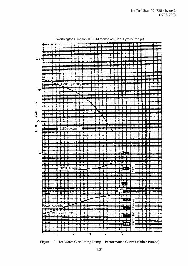
1.10 Auxiliary Components 1.24. . . . . . . . . . . . . . . . . . . . . . . . . . . . . . . 1.10.1 Accumulators 1.24. . . . . . . . . . . . . . . . . . . . . . . . . . . . . . . . . . . . . . Table 1.3 Range of Accumulators 1.25. . . . . . . . . . . . . . . . . . . . . . . . . . . . . . 1.10.2 Submarine Tank Air Pressure Charging Equipment 1.25. . . . . . 1.10.3 Pipework 1.25. . . . . . . . . . . . . . . . . . . . . . . . . . . . . . . . . . . . . . . . . . 1.10.4 Air Release Units 1.25. . . . . . . . . . . . . . . . . . . . . . . . . . . . . . . . . . . Figure 1.9 Typical Automatic Air Release Valve 1.26. . . . . . . . . . . . . . . . . . . 1.11 System Details 1.26. . . . . . . . . . . . . . . . . . . . . . . . . . . . . . . . . . . . . . 1.11.1 Introduction 1.26. . . . . . . . . . . . . . . . . . . . . . . . . . . . . . . . . . . . . . . 1.11.2 Hot and Cold Water Systems 1.26. . . . . . . . . . . . . . . . . . . . . . . . . Table 1.4 Domestic Fresh Water Systems, Pipe Size and Water Speeds 1.27Table 1.5 Equivalent Straight Pipe Length for Valves, Bends, Tees, etc.1.29Figure 1.10 Piping System Pressure Loss Chart (Fresh Water 10�C) 1.30. . . Figure 1.11 Piping System Pressure Loss Chart (Fresh Water 75�C) 1.31. . . Table 1.6 Example of Pump Fits 1.32. . . . . . . . . . . . . . . . . . . . . . . . . . . . . . . 1.11.3 Review of General Design 1.32. . . . . . . . . . . . . . . . . . . . . . . . . . . . 1.11.4 Supplies to Wash–basins and Showers 1.32. . . . . . . . . . . . . . . . . . 1.11.5 Diversity Factors for Outlets 1.32. . . . . . . . . . . . . . . . . . . . . . . . . . Table 1.7 Discharge Rate for Fittings 1.33. . . . . . . . . . . . . . . . . . . . . . . . . . . 1.11.6 Cold Water Pump 1.33. . . . . . . . . . . . . . . . . . . . . . . . . . . . . . . . . . . Figure 1.12 Diversity Factor: Number of Fittings Connected 1.34. . . . . . . . . 1.11.7 Cold Water Boost Pump 1.34. . . . . . . . . . . . . . . . . . . . . . . . . . . . . 1.11.8 Pressure at Outlets 1.35. . . . . . . . . . . . . . . . . . . . . . . . . . . . . . . . . . Figure 1.13 Wash–basin Taps and Shower Head Fittings –
Fitting of Orifice Plates 1.36. . . . . . . . . . . . . . . . . . . . . . . . . . . . . . Table 1.8 Range of Orifice Plates 1.36. . . . . . . . . . . . . . . . . . . . . . . . . . . . . . 1.11.9 Hot Water Circulation 1.36. . . . . . . . . . . . . . . . . . . . . . . . . . . . . . . Table 1.9 Conditions for Thermo-Syphon 1.36. . . . . . . . . . . . . . . . . . . . . . . 1.11.10 Selection of Calorifier 1.37. . . . . . . . . . . . . . . . . . . . . . . . . . . . . . . Table 1.10 Hot Water Piping Heat Emission and Temperature Drop 1.37. . 1.11.11 Hot Water System Peak Load 1.38. . . . . . . . . . . . . . . . . . . . . . . . . 1.11.12 Hot Water Storage Capacity 1.38. . . . . . . . . . . . . . . . . . . . . . . . . . Figure 1.14 Hot Water Temperature From Calorifier:
Time for a Storage Capacity of 0.023 m3 1.40. . . . . . . . . . . . . . . . Figure 1.15 Hot Water Temperature from Calorifier:
Time for a Storage Capacity of 0.27 m3 1.41. . . . . . . . . . . . . . . . . Figure 1.16 Hot Water Temperature from Calorifier:
Time for a Storage Capacity of 0.455 m3 1.42. . . . . . . . . . . . . . . . Figure 1.17 Hot Water Temperature from Calorifier:
Time for a Storage Capacity of 0.91 m3 1.43. . . . . . . . . . . . . . . . . Figure 1.18 Hot Water Temperature:
Time Effect of Change in Storage Capacity 1.44. . . . . . . . . . . . . 1.11.13 Electric Water Heaters 1.45. . . . . . . . . . . . . . . . . . . . . . . . . . . . . . . 1.11.14 Accumulator for Thermal Expansion 1.45. . . . . . . . . . . . . . . . . . 1.11.15 Provision for Air Removal 1.45. . . . . . . . . . . . . . . . . . . . . . . . . . . . Figure 1.19 Typical Air Collecting Vessel 1.46. . . . . . . . . . . . . . . . . . . . . . . . . .

Int Def Stan 02–728 / Issue 2(NES 728)
(xii)
Page No
Figure 1.20 Air Collecting Vessel and Manual Air Release 1.46. . . . . . . . . . . Figure 1.21 Air Collecting Vessel and Automatic Air Release 1.47. . . . . . . . . 1.12 Installation and Testing 1.47. . . . . . . . . . . . . . . . . . . . . . . . . . . . . . 1.12.1 General 1.47. . . . . . . . . . . . . . . . . . . . . . . . . . . . . . . . . . . . . . . . . . . 1.12.2 Piping Installation 1.47. . . . . . . . . . . . . . . . . . . . . . . . . . . . . . . . . . 1.12.3 Fresh Water Tank Calibration 1.49. . . . . . . . . . . . . . . . . . . . . . . . 1.12.4 Pressure Tests 1.49. . . . . . . . . . . . . . . . . . . . . . . . . . . . . . . . . . . . . . 1.12.4.1 Valves 1.50. . . . . . . . . . . . . . . . . . . . . . . . . . . . . . . . . . . . . . . . . . . . . 1.12.4.2 Fresh Water Tanks 1.50. . . . . . . . . . . . . . . . . . . . . . . . . . . . . . . . . . 1.12.4.3 Pipework in Submarines 1.50. . . . . . . . . . . . . . . . . . . . . . . . . . . . . 1.12.5 Trials 1.50. . . . . . . . . . . . . . . . . . . . . . . . . . . . . . . . . . . . . . . . . . . . . 1.12.6 Insulation 1.50. . . . . . . . . . . . . . . . . . . . . . . . . . . . . . . . . . . . . . . . . . 1.12.7 Colours and Marking 1.51. . . . . . . . . . . . . . . . . . . . . . . . . . . . . . . .
SECTION 2. NATIONAL/INTERNATIONAL REGULATIONS 2.1. . . . . . . 2.1 Materials 2.1. . . . . . . . . . . . . . . . . . . . . . . . . . . . . . . . . . . . . . . . . . 2.1.1 Material Selection 2.1. . . . . . . . . . . . . . . . . . . . . . . . . . . . . . . . . . . 2.1.2 Fresh Water Storage Tanks 2.1. . . . . . . . . . . . . . . . . . . . . . . . . . . 2.2 Installation and Testing 2.1. . . . . . . . . . . . . . . . . . . . . . . . . . . . . . 2.2.1 Colours and Marking 2.1. . . . . . . . . . . . . . . . . . . . . . . . . . . . . . . .
SECTION 3. MILITARY STANDARDS/REQUIREMENTS 3.1. . . . . . . . . . . 3.1 Drawings 3.1. . . . . . . . . . . . . . . . . . . . . . . . . . . . . . . . . . . . . . . . . . 3.1.1 System Drawings 3.1. . . . . . . . . . . . . . . . . . . . . . . . . . . . . . . . . . . 3.1.2 System Diagrammatic Arrangement Drawings 3.1. . . . . . . . . . 3.2 Materials 3.1. . . . . . . . . . . . . . . . . . . . . . . . . . . . . . . . . . . . . . . . . . 3.2.1 Material Selection 3.1. . . . . . . . . . . . . . . . . . . . . . . . . . . . . . . . . . . 3.2.2 Fresh Water Storage Tanks 3.1. . . . . . . . . . . . . . . . . . . . . . . . . . . 3.2.3 Pumps 3.1. . . . . . . . . . . . . . . . . . . . . . . . . . . . . . . . . . . . . . . . . . . . 3.2.4 Calorifiers 3.1. . . . . . . . . . . . . . . . . . . . . . . . . . . . . . . . . . . . . . . . . 3.2.5 Non-ferrous Pipework 3.1. . . . . . . . . . . . . . . . . . . . . . . . . . . . . . . 3.2.6 Steel Pipework 3.2. . . . . . . . . . . . . . . . . . . . . . . . . . . . . . . . . . . . . 3.2.7 Valves 3.2. . . . . . . . . . . . . . . . . . . . . . . . . . . . . . . . . . . . . . . . . . . . . 3.2.8 Screwed Fasteners 3.2. . . . . . . . . . . . . . . . . . . . . . . . . . . . . . . . . . 3.2.9 Jointing 3.2. . . . . . . . . . . . . . . . . . . . . . . . . . . . . . . . . . . . . . . . . . . 3.2.10 Insulation 3.2. . . . . . . . . . . . . . . . . . . . . . . . . . . . . . . . . . . . . . . . . . 3.3 System General Requirements 3.2. . . . . . . . . . . . . . . . . . . . . . . . 3.3.1 General 3.2. . . . . . . . . . . . . . . . . . . . . . . . . . . . . . . . . . . . . . . . . . . 3.3.2 Cold Water System, Services Supplied 3.2. . . . . . . . . . . . . . . . . 3.3.2.1 HM Surface Ships 3.2. . . . . . . . . . . . . . . . . . . . . . . . . . . . . . . . . . 3.3.3 Hot Water System, Services Supplied 3.3. . . . . . . . . . . . . . . . . . 3.3.3.1 HM Surface Ships 3.3. . . . . . . . . . . . . . . . . . . . . . . . . . . . . . . . . . 3.3.4 Provision of Wash–basins and Showers 3.3. . . . . . . . . . . . . . . . . 3.4 System Arrangement 3.3. . . . . . . . . . . . . . . . . . . . . . . . . . . . . . . . 3.4.1 Cold Fresh Water 3.3. . . . . . . . . . . . . . . . . . . . . . . . . . . . . . . . . . .

Int Def Stan 02–728 / Issue 2(NES 728)
(xiii)
Page No
3.4.1.1 HM Surface Ships 3.3. . . . . . . . . . . . . . . . . . . . . . . . . . . . . . . . . . 3.4.2 Emergency Fresh Water Supply to Sonar Cooling System 3.4. 3.5 Desalination Requirements 3.4. . . . . . . . . . . . . . . . . . . . . . . . . . . 3.5.1 General 3.4. . . . . . . . . . . . . . . . . . . . . . . . . . . . . . . . . . . . . . . . . . . 3.6 Fresh Water Storage and Filling 3.4. . . . . . . . . . . . . . . . . . . . . . . 3.6.1 Storage Tank Arrangements 3.4. . . . . . . . . . . . . . . . . . . . . . . . . . 3.6.1.1 HM Surface Ships 3.4. . . . . . . . . . . . . . . . . . . . . . . . . . . . . . . . . . 3.7 Pump Selection 3.4. . . . . . . . . . . . . . . . . . . . . . . . . . . . . . . . . . . . . 3.7.1 General 3.4. . . . . . . . . . . . . . . . . . . . . . . . . . . . . . . . . . . . . . . . . . . 3.8 Auxiliary Components 3.4. . . . . . . . . . . . . . . . . . . . . . . . . . . . . . . 3.8.1 Accumulators 3.4. . . . . . . . . . . . . . . . . . . . . . . . . . . . . . . . . . . . . . 3.8.2 Pipework 3.4. . . . . . . . . . . . . . . . . . . . . . . . . . . . . . . . . . . . . . . . . . 3.8.2.1 Non-ferrous Piping 3.4. . . . . . . . . . . . . . . . . . . . . . . . . . . . . . . . . . 3.8.2.2 Steel Piping 3.5. . . . . . . . . . . . . . . . . . . . . . . . . . . . . . . . . . . . . . . . 3.8.2.3 Jointing 3.5. . . . . . . . . . . . . . . . . . . . . . . . . . . . . . . . . . . . . . . . . . . 3.8.3 Valves 3.5. . . . . . . . . . . . . . . . . . . . . . . . . . . . . . . . . . . . . . . . . . . . . 3.8.4 Strainers 3.5. . . . . . . . . . . . . . . . . . . . . . . . . . . . . . . . . . . . . . . . . . 3.9 Manufacturing Practices 3.5. . . . . . . . . . . . . . . . . . . . . . . . . . . . . 3.9.1 General 3.5. . . . . . . . . . . . . . . . . . . . . . . . . . . . . . . . . . . . . . . . . . . 3.9.2 Welding 3.5. . . . . . . . . . . . . . . . . . . . . . . . . . . . . . . . . . . . . . . . . . . 3.9.3 Brazing 3.6. . . . . . . . . . . . . . . . . . . . . . . . . . . . . . . . . . . . . . . . . . . 3.9.4 Pipe Manipulation 3.6. . . . . . . . . . . . . . . . . . . . . . . . . . . . . . . . . . 3.9.5 Castings 3.6. . . . . . . . . . . . . . . . . . . . . . . . . . . . . . . . . . . . . . . . . . . 3.9.6 Fresh Water Storage Tanks 3.6. . . . . . . . . . . . . . . . . . . . . . . . . . . 3.10 Cleaning and Preservation 3.7. . . . . . . . . . . . . . . . . . . . . . . . . . . 3.10.1 General 3.7. . . . . . . . . . . . . . . . . . . . . . . . . . . . . . . . . . . . . . . . . . . 3.10.2 Fresh Water Storage Tanks 3.7. . . . . . . . . . . . . . . . . . . . . . . . . . . 3.10.3 Tubes and Pipes 3.7. . . . . . . . . . . . . . . . . . . . . . . . . . . . . . . . . . . . 3.11 Installation and Testing 3.7. . . . . . . . . . . . . . . . . . . . . . . . . . . . . . 3.11.1 Piping Installation 3.7. . . . . . . . . . . . . . . . . . . . . . . . . . . . . . . . . . 3.11.2 Fresh Water Tank Calibration 3.7. . . . . . . . . . . . . . . . . . . . . . . . 3.11.3 Inspection and Flushing 3.7. . . . . . . . . . . . . . . . . . . . . . . . . . . . . . 3.11.4 Pressure Tests 3.7. . . . . . . . . . . . . . . . . . . . . . . . . . . . . . . . . . . . . . 3.11.4.1 Fresh Water Tanks 3.8. . . . . . . . . . . . . . . . . . . . . . . . . . . . . . . . . . 3.11.5 Insulation 3.8. . . . . . . . . . . . . . . . . . . . . . . . . . . . . . . . . . . . . . . . . . 3.11.6 Colours and Marking 3.8. . . . . . . . . . . . . . . . . . . . . . . . . . . . . . . .
SECTION 4. DESIGN REQUIREMENTS/GUIDANCE 4.1. . . . . . . . . . . . . . 4.1 System General Requirements 4.1. . . . . . . . . . . . . . . . . . . . . . . . 4.1.1 Cold Water System, Services Supplied 4.1. . . . . . . . . . . . . . . . . 4.1.1.1 HM Surface Ships 4.1. . . . . . . . . . . . . . . . . . . . . . . . . . . . . . . . . . 4.1.1.2 Submarines 4.2. . . . . . . . . . . . . . . . . . . . . . . . . . . . . . . . . . . . . . . . 4.1.2 Hot Water System, Services Supplied 4.3. . . . . . . . . . . . . . . . . . 4.1.2.1 HM Surface Ships 4.3. . . . . . . . . . . . . . . . . . . . . . . . . . . . . . . . . . 4.1.2.2 Submarines 4.3. . . . . . . . . . . . . . . . . . . . . . . . . . . . . . . . . . . . . . . .

Int Def Stan 02–728 / Issue 2(NES 728)
(xiv)
Page No
4.1.3 Provision of Wash–basins and Showers 4.3. . . . . . . . . . . . . . . . . 4.2 Fresh Water Storage and Filling 4.3. . . . . . . . . . . . . . . . . . . . . . . 4.2.1 Storage Tank Arrangement 4.3. . . . . . . . . . . . . . . . . . . . . . . . . . . 4.2.1.1 Submarines 4.3. . . . . . . . . . . . . . . . . . . . . . . . . . . . . . . . . . . . . . . . 4.2.2 Sounding Tubes 4.3. . . . . . . . . . . . . . . . . . . . . . . . . . . . . . . . . . . . .
SECTION 5. CORPORATE EXPERIENCE & KNOWLEDGE 5.1. . . . . . . .
ANNEX A. RELATED DOCUMENTS A.1. . . . . . . . . . . . . . . . . . . . . . . . . . .
ANNEX B. ABBREVIATIONS AND DEFINITIONS B.1. . . . . . . . . . . . . . .
ANNEX C. PROCUREMENT CHECK LIST C.1. . . . . . . . . . . . . . . . . . . . .
ANNEX D. SAMPLE CALCULATIONS. D.1. . . . . . . . . . . . . . . . . . . . . . . . . D.1. Introduction D.1. . . . . . . . . . . . . . . . . . . . . . . . . . . . . . . . . . . . . . . D.2. General Calculations D.1. . . . . . . . . . . . . . . . . . . . . . . . . . . . . . . .
Calculation Data Sheet D1/1 – General Calculations D.3. . . . . . Table D.1 Calculation Data Sheet D.4. . . . . . . . . . . . . . . . . . . . . . . . . . . . . . D.3. Water Flow and Approximate Pipe Bore Calculation
(Cold Water System) D.5. . . . . . . . . . . . . . . . . . . . . . . . . . . . . . . . . Calculation Data Sheet D2/1 – Water Flow and Approximate Pipe Bore Calculation D.5. . . . . . . . . . . . . . . . . Calculation Data Sheet D2/2 – Water Flow and Approximate Pipe Bore Calculation D.6. . . . . . . . . . . . . . . . . Calculation Data Sheet D2/3 – Water Flow and Approximate Pipe Bore Calculation D.7. . . . . . . . . . . . . . . . .
D.4. Physical Data (Cold Water System) D.8. . . . . . . . . . . . . . . . . . . . . Calculation data sheet D3/1 – Physical Data D.8. . . . . . . . . . . . . . Calculation Data Sheet D3/2 – Physical Data D.9. . . . . . . . . . . . . Calculation Data Sheet D3/3 – Physical Data D.10. . . . . . . . . . . .
D.5. Pipe Friction Calculations (Cold Water System Main) D.10. . . . Calculation Data Sheet D4/1 – Pipe Friction Calculations D.13. Calculation Data Sheet D4/2 – Pipe Friction Calculations D.14.
D.6. Pipe Friction Calculations (Cold Water System Branches) D.15. Calculation Data Sheet D4/3 – Pipe Friction Calculations D.15.
D.7. Selection of Cold Water Pump and Cold Water Boost Pump D.17Calculation Data Sheets D5 – Selection of Cold Water Pump and Cold Water Boost Pump D.18. . . . . . . . . . . . . . . . . . . . . . . . . .
D.8. Water Flow Rates from Calorifiers D.19. . . . . . . . . . . . . . . . . . . . Calculation Data Sheet D6 – Hot Water Flow From Calorifiers D.20. . . . . . . . . . . . . . . . . . . . .
D.9. Water Flow and Approximate Pipe Bore Calculation (Hot Water System) D.21. . . . . . . . . . . . . . . . . . . . . . . . . . . . . . . . . Calculation Data Sheet D7/1 – Water Flow and Approximate Pipe Bore Calculation D.21. . . . .
D.10. Water Flow and Approximate Pipe Bore Calculation D.22. . . . .

Int Def Stan 02–728 / Issue 2(NES 728)
(xv)
Page No
Calculation Data Sheet D7/2 – Water Flow and Approximate Pipe Bore Calculation D.22. . . . .
D.11. Physical Data (Hot Water System) D.23. . . . . . . . . . . . . . . . . . . . . Calculation Data Sheet D8/1 – Physical Data D.23. . . . . . . . . . . .
D.12. Physical Data for Hot Water Branches (Aft) D.24. . . . . . . . . . . . . Calculation Data Sheet D8/2 – Physical Data D.24. . . . . . . . . . . .
D.13. Pipe Friction Calculations (Hot Water System Main) D.24. . . . . Calculation Data Sheet D9/1 – Pipe Friction Calculations D.25.
D.14. Pipe Friction Calculations (Hot Water System Branches) D.25. . Calculation Data Sheet D9/2 – Pipe Friction Calculations D.27.
D.15. Pressures Required and Available at Calorifier(s) D.27. . . . . . . . Calculation Data Sheet D10 – Pressures Required and Available at Calorifier(s) D.28. . . . . . . . . . . . . . . . . . . . . . . . . . . . .
D.16. Duty of Hot Water Circulating Pump D.29. . . . . . . . . . . . . . . . . . D.17. Capacity of Accumulators D.30. . . . . . . . . . . . . . . . . . . . . . . . . . . .
Calculation Data Sheet D11 – Duty of Hot Water Circulating Pump D.30. . . . . . . . . . . . . . . . . . Calculation Data Sheet D12 – Capacity Of Accumulators D.31.
ALPHABETICAL INDEX INDEX 1. . . . . . . . . . . . . . . . . . . . . . . . . . . . . . . . . . .

Int Def Stan 02–728 / Issue 2(NES 728)
(xvi)

Int Def Stan 02–728 / Issue 2(NES 728)
1.1
1. PERFORMANCE SPECIFICATION
Related Documents: BS 381C; BS 3602 Part 1; BS EN ISO 1461; BS EN 10028-1/2;NES 102; NES 106; NES 112; NES 119; NES 120; NES 121; NES 127; NES 155;NES 302; NES 327; NES 328; NES 329; NES 360; NES 703; NES 706; NES 707;NES 710; NES 748; NES 791; NES 797; NES 853 Parts 1 and 2; BR 820; BR 2170;BR 3013(2); BR 3013(2) Part 2; SDN 000 819 097/1-2; SDN 000 819 098/1-3;SDN 003 503 642; SDN 003 503 703; SDN 003 504 117; see also Annex A.
NOTE
The hot and cold fresh water systems are to be designed for the supply, demand andstorage capacities required to support envisaged operation of the vessel, not justagainst the minimum requirements of this standard.
1.1 Drawings
1.1.1 System Diagrammatic Arrangement Drawings
a . System Diagrammatic Arrangement drawings are to show:
(1) Layout of the system with all associated equipments, valves, fittings andpipe runs shown in their correct relative positions, so that the variousmodes of operation and control of the system can be checked;
(2) Pipe sizes, outside diameter;
(3) A list of materials proposed;
(4) The relationship to associated systems;
(5) Instrumentation and controls;
(6) Venting and drainage arrangements;
(7) Working and test pressures, see Clauses 1.12.4a to 1.12.4.3a inclusive;
(8) Definition of terminal points and interfaces between Main MachineryContractor, Contractors and Subcontractors;
(9) List of symbols used (in accordance with NES 707);
(10) Tables of calorifiers, pumps, filters and accumulators showingdesignation, duty and limiting parameters as appropriate.
b . Diagrammatic Arrangements are to be geographically correct in respect ofcompartment boundaries such as bulkheads, decks, etc. They are also to be asgeographically correct as possible in respect of major components connected toor in the system, subject to ensuring that the clarity and basic simplicity of thediagram is not compromised.
c . Drawings are to include the following information:
(1) Maximum and minimum water flows, water speeds and pressure lossesthrough each branch pipe;
(2) Data Sheets of pipe sizes supporting the above.
d . System Diagrammatic Arrangement drawings are to form Basis Informationwhich is to be kept up�to�date by the Shipbuilder.

Int Def Stan 02–728 / Issue 2(NES 728)
1.2
1.1.2 System Ship Arrangement Drawings
a . System Ship Arrangement drawings are to be drawn to scale, superimposed onthe hull in plan and elevation, to show the location of the system andcomponents relative to the hull, bulkheads, decks and other items of machineryand equipment.
b . System Ship Arrangement drawings are to indicate the positions and identity offlanged joints, orifice plates, screwed connections, capillary, brazed and weldedjoints in addition to items (1) to (9) inclusive of Clause 1.1.1a .
1.1.3 Equipment Drawings
a . Equipment drawings showing major items of equipment are to be prepared bythe equipment manufacturers. Equipments for which drawings are requiredinclude:
(1) Calorifiers;
(2) Pumps;
(3) Strainers;
(4) Accumulators.
b . Equipment drawings are to show:
(1) Overall dimensions;
(2) Mounting arrangement and jacking points;
(3) General arrangement;
(4) Terminal points;
(5) Lifting points and position of Centre of Gravity, dimensioned.
(6) Maintenance envelope, showing accessibility for maintenance, e.g.rodding points, etc, and space required for withdrawal/replacement ofcomponent parts, see NES 302;
(7) Parts List;
(8) Assemblies;
(9) Sub�assemblies;
(10) Circuit Diagrams (mechanical and electrical).
1.2 Materials
1.2.1 Material Selection
a . Materials for components are to be selected to reduce corrosion and erosion to aminimum, be non-toxic and consistent with reasonable cost and ease ofmanufacture.
b . Pipe clips are to be of steel, galvanized in accordance with BS EN ISO 1461.
Int Def Stan 02–728 / Issue 2(NES 728)
1.3
1.2.2 Fresh Water Storage Tanks
a . Fresh Water (FW) storage tanks are generally to be built as an integral part ofthe hull. Where constructed independent of the hull structure, storage tanksare to be of steel complying with NES 791.
b . Access ladders inside storage tanks are to be of steel, galvanized in accordancewith BS EN ISO 1461.
c . Non�ferrous fittings are not to be used in FW storage tanks.
1.2.3 Accumulators
a . Accumulators are to have an outer steel shell and an inner separator bag ofsynthetic rubber.
1.2.4 Non-ferrous Pipework
a . Exposed piping in bathrooms, galleys and cabins is to be chromium plated.
1.2.5 Steel Pipework
a . Sounding tubes, air escapes and sections of suction pipes within FW tanks areto be carbon steel complying with BS 3602, Part 1, Hot Finished Seamless (HFSGrade 360) or Cold Finished Seamless (CFS Grade 360), galvanized internallyand externally. Connecting sleeves and ring flanges are to to be of galvanizedsteel complying with BS 1501 Part 2, and BS EN 10028-1/2 (see BR 3013(2),Part 2).
1.2.6 Valves
a . Materials for valves are given in NES 360.
b . Push cocks for supply to cabin, bathroom, workshop and office washbasins,mess draw�off, etc, are to be of chrome�plated brass.
1.3 System General Requirements
1.3.1 General
a . Domestic hot and cold FW systems are to be designed:
(1) To deliver the specified quantities of FW with the minimal head loss,noise, and pumping power commensurate with economically sized piping.The installation is to be planned in association with other services tomaintain adequate headroom and facilitate future refit work;
(2) To ensure that the system will provide and maintain the required degreeof cold water purity in service as specified in BR 820;
(3) To obtain, on Surface Ships, a degree of insurance against action damageby dividing the system and providing storage tanks, circulating pumps,calorifiers, etc, both forward and aft. This will ensure an independentworkable system at each end of the ship. On Submarines this duplicationis not required;
(4) To minimum space and weight requirements;
(5) To meet zoning requirements laid down in NES 119.
Int Def Stan 02–728 / Issue 2(NES 728)
1.4
b . The systems are to cater for a daily consumption allowance of 200 litres per dayper member of complement (excluding boiler feed) for surface vessels and90 litres per day per member of complement for Submarines. The allowance forSurface Ships is to be supplemented by the requirement for turbine washing,aircraft washdown and ship husbandry (including superstructure washdown),i.e. 50 litres per turbine per day, 500 litres per aircraft per day and 500 litres perday for ship husbandry.
c . The systems are to be designed to conform to the requirements of NES 797 andNES 710.
d . In Surface Ships systems are to be designed to provide a pressure of 0.35 bar atthe highest and most remote points and to meet the requirements of any specialequipment needing greater pressure. A bridge window washer system is to befitted capable of providing a minimum pressure of 1.4 bar at the bridge window.
1.3.2 Hot Water System, Services Supplies
1.3.2.1 Surface Ships
a . For Surface Ships' calorifier capacity, see Clause 1.11.10b .
1.3.2.2 Submarines
a . In Submarines the calorifier is to be capable of supplying sufficient water at atemperature of 71°C to meet a flow rate of 4.5 litres per hour per member ofcomplement or as specified in the Statement of Technical Requirement (STR).
1.3.3 Battery Top-up Water (Submarines)
a . In Submarines, water for battery top�up is to be supplied from the FW systemthrough a demineralizer.
1.4 System Arrangement
1.4.1 Cold Fresh Water
1.4.1.1 Surface Ships
a . The system is to comprise storage tanks with associated pumps, suction,discharge, filling and transfer arrangements. The pumps are to dischargedirect to the FW main.
b . Two FW storage tanks, or groups of tanks, are to be fitted, one forward and oneaft. The precise number and size of tanks are to suit the space available in eachclass of ship.
c . The total tank capacity is to be as defined in Clause 1.6.1.
d . A diagrammatic arrangement of a typical Domestic Cold Water System for aSurface Ship is shown in Figure 1.1.
e . Suction and delivery valves, with the necessary connections, are to be fitted toenable the pumps to deliver FW to the FW main and to transfer water within theship.

Int Def Stan 02–728 / Issue 2(NES 728)
1.5
f . The system is to be a continuous running pump system, with the minimumnumber of pumps operating at a time. The pumps are to be capable of supplyingthe services in all conditions with little pressure variation over the deliveryrange. At least two pumps are to be installed, one at each end, with only onerunning at a time, see Clause 1.11.2m . Adequate arrangements are to be madeto provide against pumps overheating during periods of no discharge.Start/Stop facilities are required:
(1) Locally, adjacent to the pumps;
(2) Remotely, in or adjacent to Damage Control HQ to permit Starting andStopping of pump(s) in NBCD State 1.
g . The suction pipework from the FW storage tanks to the cold water pumps is tobe arranged so that either pump associated with a group of tanks can draw fromany tank in that group.
h . The suction pipework is to include the necessary isolating valves, non�returnvalves and a 1.5 mm diameter aperture size pump suction duplex strainer toconform to NES 748.
i . The discharge pipework from each pump should include an isolating valve and anon�return valve which is to be fitted as close to the pump as possible.
j . Pressure indicators are to be fitted at the following positions:
(1) At each pump suction and discharge. These indicators are normallyprovided as part of pump;
(2) On the FW main near the junction with the pump risers;
(3) At the highest points in the system.
k . Local and remote reading pressure indicators are to be supplied and fitted in theFW main for surveillance equipment. The remote position is to be in the ShipControl Centre (SCC).
l . Hose connections are to be fitted on the suction and delivery sides of the FWpumps for use with a portable pump in an emergency.
m . A filling and transfer line is to be fitted throughout the length of the ship toconnect the various groups of FW tanks to the desalination plant and FW fillingdeck connections. The filling and transfer line will be used for supplyingdistilled water to the FW storage tanks and also for supplying the tanks withwater from the deck connections and for transferring water from one group oftanks to another. In ships with steam boilers and more than one desalinationplant the filling lines between the plants and the feed tanks, and the plants andthe FW tanks, are to be arranged so that one plant can distil to feed tanks andone to ship's tanks independently of each other.
n . The FW main supply from the storage tank is to be led forward and aftthroughout the vessel, generally on the lowest continuous access deck, withbranches led to the various services, including the hot water calorifiers.Wherever possible a ring main is to be provided with the pumps discharginginto the cross�connections. In the case of the smaller vessels where a ring mainmay be impracticable, a main line and spur type of system is permitted.

Int Def Stan 02–728 / Issue 2(NES 728)
1.6
(SE
E F
IGU
RE
1.3
)
Figure 1.1 – Typical Domestic Cold Water System for Surface Ships
NO
TE
:S
ymbo
ls u
sed
are
to c
onfo
rm to
NE
S 7
07
(SE
E F
IGU
RE
1.3
)

Int Def Stan 02–728 / Issue 2(NES 728)
1.7
o . Supplies of FW are to be maintained to essential services when the remainingservices have been isolated, due to an emergency or for rationing. The isolationis to be achieved by the closing of a limited number of valves on the FW main.The essential services include:
(1) Medical and Dental spaces, see NES 106;
(2) Galleys and associated spaces, see NES 121;
(3) Drinking Water Coolers;
(4) Bridge Window Washer System, see NES 112;
(5) Bathrooms used as cleansing stations, see NES 120;
(6) FW cooling to guns.
p . Strainers with a 1.5 mm diameter mesh are to be fitted as required beforespecial items of equipment (e.g. the bridge window washer system where onestrainer is fitted in the common main that supplies all window washers).Non�concussive push cocks are to be used as isolating valves to individualwindow washers.
q . Isolating valves are to be fitted in the FW main so that supplies can bemaintained if sections of the main are damaged.
r . Branches are to be fitted with lockable isolating valves close to the main. Valvesare to be provided with service pattern locks as necessary.
s . FW leads are to be arranged so that they can be readily drained and emptied.Branches exposed at atmospheric temperatures are to be arranged so that theycan be isolated and drained if temperatures below 0°C are expected orencountered. For this purpose, isolating and drain valves are to be fitted.
t . In places where water may remain after the system has been drained (see Clause1.4.1.1s ), screwed drain plugs are to be fitted. A light alloy or nickel silver tallyplate, engraved `FROST PLUG' is to be fitted in a clearly visible position at eachplug. Half a complete set of plugs is to be provided to the ship as spares.
u . Small air chambers are to be arranged, at the top of each riser and at the end ofhorizontal lines, to prevent water�hammer.
v . Automatic air release units are to be as specified in Clause 1.10.4a . Thedetailed requirements for air removal are given in Clauses 1.11.15a to 1.11.15e inclusive.
w . Flexible assemblies fitted in the system are to conform to the requirements ofNES 710 and NES 797.
x . Emergency leads from the FW main, are to be led to the vicinity of cabinetsnormally cooled by tepid water (see Clause 1.4.3a ).
y . Cross connections between fresh and sea water systems are not permitted.Where it is necessary to supply fresh and sea water alternatively to equipment,or to supply FW to certain auxiliary machinery, the FW is to be supplied bymeans of a hose, connected to the supply end only or an open funnel fillingconnection is to be used.

Int Def Stan 02–728 / Issue 2(NES 728)
1.8
z . Where the required system total head exceeds 4 bar or 90% of the maximumhead available from the cold FW pump selected, whichever is the lower, a boostsystem, supplied by a continuously running self�priming pump, is to beprovided to serve the higher outlets. The most convenient point to install theboost pump is to be selected so as to be close to the maximum demand on theboost circuit and to suit the ship's arrangement. The point selected is to serveall outlets on the top decks and is to be suitable for use with any one cold waterpump out of service. In large ships it may be necessary to fit more than oneboost pump.
aa . The boost system is to be provided with a return to the FW main, with orificecontrol, to ensure a continuous flow through the boost pump thus providing acooling circuit. The boost system is to be provided with isolating valves,non�return valve, strainer and pressure indicators on either side of the pump.See Figure 1.1.
1.4.1.2 Submarines
a . The system is to comprise a distribution main supplied from two or more FWstorage tanks pressurized either from the Auxiliary Vent and Blow System(AV&B) or a continuous running pump system. A separate weapons spray tankis to be fitted.
b . One group of storage tanks is to be fitted. The precise number and size of tanksare to suit the space available in each particular Submarine, but see Clause1.6.2.2a .
c . The total tank capacity is to be as defined in Clause 1.6.1a.
d . A diagrammatic arrangement of a typical Domestic Cold Water System for aSubmarine is shown in Figure 1.2.
Figure 1.2 Typical Domestic Cold Water System for Submarines
Escape BHD
EmergencyDrinkingWater
LS
UsersUsers
Users To HotWaterSystem
From AV&B
LS
Containment Zone
FWTank
FWTank
Users
NOTE: Symbols used are to conform to NES 707

Int Def Stan 02–728 / Issue 2(NES 728)
1.9
e . The normal system operating pressure is to be 2 bar.
f . Supply to the storage tanks is to be from the Submarine's desalination plant viathe feed transfer and FW filling system or as specified in the STR.
g . The system is to permit all tanks being filled from an outboard source by hose,through an inboard hose connection situated near a hatch. This connection isto be fitted with a ball type stop valve and strainer. A FW filling control stationis to be sited in a convenient position.
h . Arrangements are to be made so that the feed water may be used to augment theFW supply.
i . The system is to be so arranged that one storage tank can supply water to themain while the other is being filled from the FW filling line.
j . A 3 mm diameter hole is to be drilled in the lowest pipework downstream of eachpyrotechnic locker flooding isolating valve to indicate any leakage past theisolating valve.
k . The forward weapons spray tank is always to be full and to be capable of beingreadily pressurized. The system operating pressure being indicated in the STR.
l . Facilities are to be provided for directly connecting a shore FW/Sea Water (SW)supply to the spray system as well as SW back�up from the High Pressure (HP)bilge system or a suitable alternative system.
m . The portion of piping within the containment boundary is to be suitable fortesting to containment pressure. Alternatively the system is to be fitted withreadily accessible isolating valves at and outside, but as close as is practicable to,the containment boundary.
n . Valves, tested to the full bulkhead design pressure, are to be fitted on both sidesof penetrations of main and escape bulkheads and on the outside ofcontainment boundary penetrations.
1.4.2 Hot Fresh Water Systems
1.4.2.1 Surface Ships
a . One or more hot water systems are to be installed. Each system is to comprise acalorifier, an accumulator, circulating pump, valves and associated fittings.Each system is to be pressurized by the cold FW supply.
b . Each hot water system is to be arranged as a ring main with branches to thevarious outlets. The length of branches to outlets are to be kept to a minimumto limit the wastage of hot water.
c . Where more than one hot water system is installed it may be advantageous tocross�connect the ring mains to provide a safeguard against an emergencycondition when either calorifier is out of action. Each cross�connection is to beprovided with a locked�shut isolating valve.
d . A diagrammatic arrangement of a typical Domestic Hot Water System for a Surface Ship is shown in Figure 1.3. See also Annex D.
e . The calorifiers are to be supplied with water by a branch from the cold FW main,led to the bottom of the calorifier and fitted with an isolating valve andnon�return valve at the calorifier. The hot water outlet pipe is to be connected tothe crown of the calorifier.

Int Def Stan 02–728 / Issue 2(NES 728)
1.10
(SEE Figure 1.1)
Figure 1.3 Typical Domestic Hot Water System for Surface Ships
NOTE: Symbols used are to conform to NES 707
f . The accumulator is to be located adjacent to the calorifier and connected to thecold water supply just before it enters the calorifier (see Clause 1.10.1a ).
g . During periods of low demand, hot water is to be circulated around the ringmain. The circulation is to be sufficient to ensure that the temperaturedifference between the calorifier outlet and return is not in excess of 5°C.
h . For small systems and when there is adequate vertical lift, a thermo�syphonsystem will provide the required circulation.
i . For larger systems a circulating water pump is to be provided in the returnpiping which is to be connected to the bottom of the calorifier. A non�returnvalve and pump suction and discharge isolating valves are to be provided. Abypass is to be fitted around the circulating pump for natural circulation in theevent of pump failure. The procedure for determining if a circulating pump isrequired is given in Clause 1.11.9c.

Int Def Stan 02–728 / Issue 2(NES 728)
1.11
j . The number of hot water systems and hence calorifiers is to be decided bycombining the hot water requirements into convenient groups. Eachindividual calorifier's share of the total heating capacity is to be in proportion tothe design flow rate of that calorifier's hot water system.
k . The storage capacity is to ensure that the temperature of the hot water outletsdoes not drop below 50°C during a peak demand from a system initially at 65°C.Storage capacity calculations are given in Clause 1.11.
l . The general requirements for the cold water systems given in Clauses 1.4.1.1p to 1.4.1.1v apply to hot water systems.
m . Hot water boost systems should be avoided because pumps are large and costly,therefore use local electric heaters supplied from the cold water system toprovide hot water at a high level within the ship. Where hot water boost pumpsare essential, their design and installation is to be based on the same practice asthe cold water boost pump, see Clauses 1.4.1.1z to 1.4.1.1aa inclusive.
n . Local water heaters will always be powered by electricity.
1.4.2.2 Submarines
a . One hot water system is to be installed consisting of a calorifier pressurizedfrom the cold FW supply.
b . A diagrammatic arrangement of a typical Domestic Hot Water System for aSubmarine is shown in Figure 1.4.
Figure 1.4 Typical Domestic Hot Water System for Submarines
NOTE: Symbols used are to conform to NES 707
c . The calorifier, which is to be electrically heated, is to have a storage capacity of0.55 m3 or as indicated in the STR.

Int Def Stan 02–728 / Issue 2(NES 728)
1.12
d . The hot water system is to be in the form of a ring main with naturalthermo�syphon circulation. Branches are to be taken from the supply side only.A non�return valve is to be fitted in the return line to the calorifier.
e . The heating capacity of the calorifier is to be given and include adequatecapacity for those items listed as a minimum as in Clause 4.1.2.2a .
f . Penetration of containment and escape bulkheads by the hot water system is tobe avoided by the use of local electric water heaters supplied by the cold FWmain.
1.4.3 Emergency Fresh Water Supply to Sonar Cooling System
a . On some Surface Ships an emergency FW supply is required for the SonarCooling System. Hose connections with lockable valves and portable hoses toconnect between the Domestic Cold Water System and a similar connection onthe Sonar Cooling System is to be provided for the supply and similarconnections for the return between the Sonar System and the Filling/TransferMain. These connections are in accordance with the requirements of NES 102.
1.5 Desalination Requirements
1.5.1 General
a . In Surface Ships and Submarines the desalination plants are to conform to therequirements of NES 328.
b . Reverse Osmosis and Low Pressure (LP) plants are to have a dedicated seasuction sited forward of, and on the opposite side of, the ship to that of Bilge andSanitary discharges.
c . An Auto Chlorination Unit is always to be fitted. However, an Ultra�Violet Unitmay be fitted in addition to an Auto Chlorination Unit.
1.5.2 Submarines
a . An additional allowance of water is to be made for make�up of the primary andsecondary propulsion system.
1.6 Fresh Water Storage and Filling
1.6.1 Storage Capacity
a . Provision is to be made for the following minimum quantities of FW to be storedonboard all Surface Ships and Submarines:
(1) All Surface Ships:
(a) 1.0 m3 per person of complement
(b) 2.5 m3 per aircraft (where applicable);
(c) 2.5 m3 ships husbandry;
(d) 0.25 m3 per turbine - ship and aircraft (where applicable).

Int Def Stan 02–728 / Issue 2(NES 728)
1.13
(2) Submarines:
(a) 0.23 m3 per person of complement in or as indicated in the STR:
b . Consideration must be given to increasing the levels quoted for Surface Shipsthat will spend significant periods of their operational service close in shorewhere water production plants cannot be operated effectively.
1.6.2 Storage Tank Arrangement
1.6.2.1 Surface Ships
a . Generally, storage tanks are to form an integral part of the ship's structure andare to be strongly constructed, well stiffened and fitted with divisional plates toprevent surging and thumping when the ship rolls heavily. The tanks are to bearranged so that air pockets will not form during filling and such that the waterwill level itself as fast as it is delivered; escape and limber holes being cut inbeams, frames, etc, as necessary to facilitate filling and draining. Where airpockets are unavoidable, an additional air escape may be fitted.
b . The internal structure of each tank is to allow ready access to all parts of thetank for preservation, by abrasive blasting and painting and for inspection andcleaning.
c . Welding is to conform to NES 706.
d . For tank preservation see Clause 3.10.2a .
e . A high standard of inspection of all welded joints in FW tanks is essential tomaintain FW purity, see Clauses 3.9.6b and 3.9.6c . Where the requisitestandard of inspection cannot be met, then FW tanks are to be separated fromother tanks containing SW or oil by means of watertight coffer-dams.
f . For calibration of tanks see Clauses 1.12.3a to 1.12.3c inclusive.
g . Access to tanks is to be provided by manholes fitted with raised coamings andwatertight covers. The covers are to be secured by through bolts or studs inaccordance with the latest approved practice. For Submarine applications, thelatest approved practice, e.g. flush manholes, is also to be followed.
h . Ladders in FW tanks are not to be coated but are to be galvanized,see Clause 1.2.2b .
i . Piping, gearing etc, of any description are not to be led through the tanks exceptwhen required for the operation of the FW system. For restriction on the use ofnon�ferrous fittings in tanks see Clause 1.2.2c .
1.6.2.2 Submarines
a . The number and allocation of FW tanks will be specified in the appropriateSTR. (See also Clause 4.2.1.1).
1.6.3 Filling Arrangements
1.6.3.1 Surface Ships
a . Provision is to be made for receiving FW through screwed deck connections andelbow adaptors from shore, from water�boats alongside and from water�carriersduring Replenishment�At�Sea (RAS). Provision is also to be made for thesupply of water to ships alongside or in company.

Int Def Stan 02–728 / Issue 2(NES 728)
1.14
b . The filling system is to be designed to enable the following pumping rates to bemet:
(1) Ships of Frigate/Destroyer size and above 100 m3/h;
(2) Ships below Frigate/Destroyer size 50 m3/h.
c . In Surface Ships a minimum of four shore filling connection points are to befitted, sited as follows:
(1) For ships of length between 109 m and 131 m:
(a) Two connections between 40 m and 49 m from the forward end, oneport and one starboard;
(b) Two connections between 40 m and 49 m from the aft end, one portand one starboard.
(2) For ships of length between 150 m and 213 m:
(a) Two connections between 35 m and 53 m from the forward end, oneport and one starboard;
(b) Two connections between 35 m and 53 m from the aft end, one portand one starboard.
d . In ships less than 100 m in length the provision of two points is acceptable,providing that they are sited near to the centre line, one forward and one aftwithin the ranges specified in Clause 1.6.3.1c , with direct access across the deckfrom either side.
e . Storage tanks are to be filled via the filling and transfer line, through deckconnections sited as specified in Clause 1.6.3.1c . Each deck connection is to bearranged to take an adaptor fitted with two 65 mm female instantaneous hoseconnections to SDN 000 819 097/1-2.
f . In multi�spot ships, the deck connections are to be fitted in the deck or ship sidein the positions specified in Clause 1.6.3.1c , and cross�connected. Leads are tobe taken from the cross�connections to the filling and transfer line.
g . For RAS, deck connections are to be readily accessible to the RAS areas. Eachdeck connection is to be provided with an adaptor to SDN 000 819 098/1-3 totake a 165 mm flange.
h . In order to avoid the risk of excessive pressure in the FW storage tanks duringfilling operations, filling funnels are to be fitted above the crown of each storagetank. Each filling funnel is to be filled with a light alloy cover provided with alocking arrangement. The filling and transfer main is to discharge into thefilling funnels. A ball/plug valve, selected from NES 360, is to be fitted in thefilling pipe immediately above the filling funnel and also at the tank top. Thepipe below the filling funnel to the tank is to be at least one size larger than thefilling and transfer main.
i . Aerating roses are to be fitted on the filling line within the tanks.
j . Each FW tank is to be fitted with a continuous distant reading type contentsindicator, indicating at the FW filling station. The sounding tube is to be usedfor checking the continuous reading gauge as necessary.
k . Special precautions are to be taken to ensure that the hoses used for filling thestorage tanks, and the tanks themselves are thoroughly clean when takingwater on board, (see BR 820).

Int Def Stan 02–728 / Issue 2(NES 728)
1.15
1.6.3.2 Submarines
a . Normal supply to the storage tanks is to be from the desalination plant via thefeed transfer and FW filling systems. Where FW tanks are sited adjacent to theWeapons Storage Compartment (WSC) they are not to be supplied directly fromthe desalination plants unless the water is first cooled.
b . The system is to permit all tanks (excluding emergency cooling cylindrical andjacket tanks) being filled from an outboard source by hose, to be through aninboard hose connection situated near the engine room hatch. This connectionis to be fitted with a ball type stop valve and strainer. The FW filling controlsystem is to be sited at the position specified in the STR.
c . Arrangements are to be made so that feed water may be used to augment the FWsupply.
d . The system is to be so arranged that one storage tank can supply water to themain while the other is being filled from the FW filling line. The tank to theWSC spray system is always to be full.
e . Each tank is to be fitted with a remote reading contents gauge indicating at theFW filling station. The tank supplying the WSC spray grid is to be fitted with alow-level alarm.
1.6.4 Sterilization
a . Fittings to facilitate the sterilization of the FW in the storage tanks are to beprovided to each tank and are to consist of a mixing tank with leads to the fillingfunnels in compliance with the arrangements shown on SDN 003 504 117. Themixing tank is provided to introduce a chlorinating agent into the tank to thestrength specified in BR 820.
b . Water purifiers may be fitted between the desalination plant and the filling andtransfer main for use when unavoidably distiling in potentially polluted waters;see NES 328.
c . Former distinctions between the standards required for drinking and washingwater should not be maintained.
d . All FW taken from barge or shore should be chlorinated to a chlorine content of0.2 ppm.
1.6.5 Sounding Tubes
a . In Surface Ships a sounding tube is to be fitted to each FW tank and is to be 60.3mm pipe size which is of suitable bore to pass the MOD standard sounding tape.The pipe is to be similar to that used for air escapes (see Clause 1.6.6b ). Thesounding tube may be combined with one of the tank's air escapes in which casethe tube is to be perforated within the tank just below the crown to provide anopen area equal to that of the air escape. See SDN 003 503 642 andSDN 003 503 703.
b . The sounding tube is to be vertical and is to extend to within 100 mm of thebottom of the tank. In order to prevent damage to the tank coating, the bottomof the sounding tube is to be sealed. Perforations around the circumference ofthe tube are to be made to permit entry of the water.
c . The upper end of the sounding tube is to be provided with a locked screw capand is to be fitted in the vicinity of the filling funnel. Where practicable,sounding tubes are to be arranged alongside bulkheads, etc, in order that theirupper ends may extend permanently about 300 mm above the deck. Elsewherethey are to be fitted with locked watertight deck plates.

Int Def Stan 02–728 / Issue 2(NES 728)
1.16
d . Sounding tubes are to be hot�dip galvanized internally and externally after allwelding and machining has been completed.
1.6.6 Air Escapes
a . Two air escapes are to be fitted at the highest position in each tank, the twopositions being as remote from one another as can be arranged. For tanks ofcapacity 75 tonne or more the pipes are to be 60.3 mm outside diameter (OD)pipe size; for tanks under 75 tonne capacity the pipes are to be 42.4 mm OD pipesize. Where a filling funnel is not used and the tank is filled directly, then itmust be ensured that the total area of the air escapes is not less than the tankfilling pipe.
b . Materials for air escape pipes are given in Clause 1.2.5a . The pipes are toconform to BR 3013(2), Part 2 and generally are to have a wall thickness of3 mm. From inner bottom to just above the floor plates in machinerycompartments, the pipes are to have a wall thickness of not less than 10 mm.
c . Air escape pipes are to terminate in a `goose neck' within the gas citadel and atleast 2 m above the RED RISK ZONE. The goose neck is to be fitted with a fixedperforated closure and led clear of fuel oil air escapes. Air escape pipes are not toterminate in living spaces unless unavoidable.
d . Care is to be taken to ensure that air escape pipes from FW tanks are notcombined with air escapes from any other tank.
e . Air escape pipes are to be led as directly as possible; pockets and long horizontalportions are to be avoided. Pipes are not to penetrate any main transversewatertight bulkhead.
1.7 Pump Selection
1.7.1 General
a . The information in Clauses 1.7.2 to 1.7.6 applies to pumps for Surface Shipsonly.
b . Pumps are to conform to NES 327.
c . Generally, electric motor driven self�priming centrifugal pumps are to be fittedfor the distribution of FW throughout the ship.
d . For number of pumps to be fitted, see Clause 1.11.2m.
e . For operation of pumps in NBCD State 1, see BR 2170.
1.7.2 Cold Water Pump
a . The cold water pump is to pressurize both the cold and hot FW systems.
b . The total pressure is inclusive of a maximum suction lift of 7.6 m and allowanceis to be made for a minimum gauge pressure of 0.35 bar at the highest point, or1.40 bar for Bridge windows whichever is the greater. Friction losses are to beadded when assessing what height the pumps can be used to supply.
c . Performance curves for the two cold FW pumps are given in Figure 1.5 andFigure 1.6 respectively.
d . It is possible to obtain pumps with non�standard impellers to give modifiedperformance.

Int Def Stan 02–728 / Issue 2(NES 728)
1.17
Figure 1.5 – Domestic Cold Water Pump – Performance Curves
Worthington Simpson Self Priming Pump 10 m3/h (Symes No. 4.1.5.1)
Head/Quantity
3500 rev/min
Absorbed Power
Pump Efficency
Quantity m3/h

Int Def Stan 02–728 / Issue 2(NES 728)
1.18
Figure 1.6 – Domestic Cold Water Pump – Performance Curves
Worthington Simpson Self Priming Pump 10 m3/h (Symes No. 4.1.5.2)
Head/Quantity
3500 rev/min
Absorbed Power
Pump Efficency
Quantity m3/h
kW
0.5
1.0
1.5
2.0E
ffice
ncy
%
Pum
p In
put P
ower
0

Int Def Stan 02–728 / Issue 2(NES 728)
1.19
1.7.3 Cold Water Boost Pump
a . If it is necessary to use a pump for boost duty, the pump selected is to be of theself�priming type so as to reduce the period of running with no cold water feed,in the event of a temporary failure of the main cold water system.
b . Consideration is to be given to fitting an electrical cut�out on the boost pump tobe initiated by lack of water at the suction.
1.7.4 Hot Water Pump
a . The hot water pump is to provide a circulation round the ring main duringperiods of low demand to limit the temperature drop between the calorifieroutlet and return to about 5°C.
b . Requirements for calculating the capacity of the hot water pump are given inClause 1.11.9c .
c . A pump of simple design, having a continuously falling head/quantitycharacteristic, preferably fairly `steep' to maintain a re�circulated flow at peakperiods, is adequate for the circulating duty. At peak periods the pressure dropin the ring main may exceed the pressure available from the hot watercirculating pump. In these circumstances there will be no need for circulationof water but the circulating pump is to be capable of operation for relatively longperiods under this `run out' condition, during which it may have a very low NetPositive Suction Head (NPSH) available.
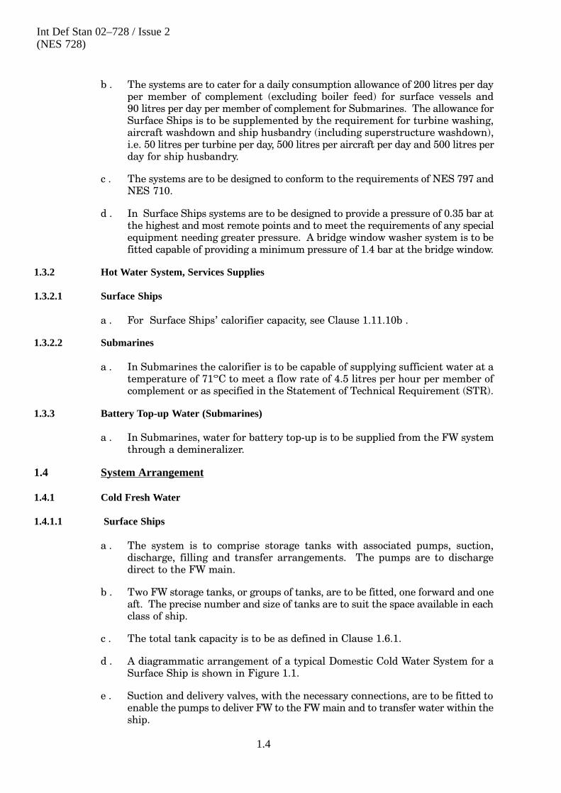
d . Performance curves for the preferred hot FW pump are given in Figure 1.7 andothers in Figure 1.8.

Int Def Stan 02–728 / Issue 2(NES 728)
1.20
Figure 1.7 – Hot Water Circulating Pump – Performance Curves (Preferred)
Worthington Simpson 1D S5 0.55 m3/h (Symes No. 4.1.5.1)
Quantity m3/h
Head Quantity
1750 revs/min
Pump Efficiency
Water at 15 �C
Power Absorbed
kW
0.1
0.2
Effi
cenc
y %
Pum
p In
put P
ower
0
Int Def Stan 02–728 / Issue 2(NES 728)
1.21
Figure 1.8 Hot Water Circulating Pump—Performance Curves (Other Pumps)
Worthington Simpson 1DS 2M Monobloc (Non–Symes Range)
Head Quantity
Water at 15 �C
Power Absorbed
1150 revs/minN
PS
H
NPSH Required
bar
0.05kW
0.04
0.03
0.02
0.01
0.1
0.2
0
Pum
p In
put P
ower

Int Def Stan 02–728 / Issue 2(NES 728)
1.22
1.7.5 Hot Water Boost Pump
a . The use of a hot water boost pump is to be avoided by using local electric waterheaters, supplied direct from the cold water system, (see Clause 1.8.3b ).
1.7.6 Pump Protection
a . If a cold water pump is allowed to continue to run when no fluid is passingthrough it overheating may result. A continuous flow of water sufficient to coolthe pump can be maintained by the use of a leak�off from the pump supply.
b . With the use of a leak�off there is a continuous flow for which allowance must bemade when selecting the pump. An orifice plate is placed in the return line fromthe pump discharge to the storage tank to limit the pressure of the cooling waterentering the storage tank, in the case of a boost pump, from the pump dischargeto the supply main.
c . The orifice plate is to be sized as follows:
(1) Determine from the pump performance data the minimum flow necessaryto protect the pump. Use this flow to establish the friction loss in thereturn piping from the orifice to the storage tank.
(2) Use the approximate formula:
d � 10.50Q
H
where d = orifice bore (mm)
Q = flow (m3/h)
H = total head across orifice (m).
d . When any specific pump has been selected, a check is to be made on themanufacturer's characteristic curves to ensure that the electric motor suppliedwith the pump will not be overloaded when the pump runs out on itscharacteristic.
1.8 Calorifiers
1.8.1 Types of Equipment
a . The types of equipment considered are:
(1) Domestic calorifiers;
(2) Calorifiers, for individual or special services, for use in isolated positionsand for emergency use.
b . Selection of calorifiers is discussed in Clause 1.11.10a .
1.8.2 Heating Capacity
a . The capacity of the calorifier in:
(1) Surface Ships are to meet as a minimum the requirements ofClause 1.11.10b;
(2) Submarines are to meet as a minimum the requirements ofClause 4.1.2.2a.

Int Def Stan 02–728 / Issue 2(NES 728)
1.23
1.8.3 General Requirements
a . All calorifiers are to conform to the relevant requirements and design datagiven in NES 329 and fitted as required in Clause 1.4.
b . Isolated positions which cannot conveniently be serviced by the hot watersystem are to be supplied by individual electric water heaters. Individualelectrical water heaters are also required in medical compartments foremergency use, see Table 1.1.
Ship ComplementH t
Locationover1300
1300- 801
800 -501
500 -301
under301
HeatInput(kW)
Capacity (m3)(kW)
0.068 0.068 - - - 3
Sterilizing Room - - 0.023 0.023 - 2
Treatment Room 0.023 - - - - 2
Emergency OperatingTheatre or Station
0.023 0.023 0.023 0.023 - 2
Table 1.1 – Scale of Electric Water Heaters
c . A preferred range of other calorifiers is shown in Table 1.2.
Capacity (m3) Heat Input (kW)
0.023 2
0.068 14
0.113 10
Table 1.2 – Range of Alternative Calorifiers
d . Steam/water mixers may be used where specified in the STR and providednon�return valves are fitted in the steam and cold water supply lines.
1.8.4 Submarines
a . In Submarines, the hot water tank is to be electrically heated andthermostatically controlled to limit the water temperature to 71°C. The tank isto have a storage capacity of 0.546 m3 and a heating capacity of 34 kW. This isequivalent to a duty of 0.0045 m3 per hour per person of complement. Thecapacity and duty of the hot water system may be varied due to otherconstraints and reference is to be made to the STR.
b . Heating supplies are to be controlled by thermostats sited in the vessel's hotwater calorifier or tank.
1.9 Drinking Water and Cooled Fresh Water
1.9.1 Drinking Water Tanks
a . In Surface Ships drinking water tanks complete with stands, cocks, drip pansetc, are to be supplied and fitted as follows:
(1) One - 150 litre tank in each First Aid Post;
(2) One - 50 litre tank in each Engine and Boiler Room;
(3) One - 20 litre tank in each Auxiliary Machinery Room;

Int Def Stan 02–728 / Issue 2(NES 728)
1.24
(4) In order that additional bulk supplies of FW are available at First AidPosts and Fire Party Posts, stowage and securing arrangements are to beprovided for plastic `Jerry' cans NSN 0284/120-7251.
Note First Aid personnel, closed up at their Action Stations, will carrypersonal water bottles, NSN A 249/973-6972, to provide animmediate supply of FW for first aid.
b . Where a cooled drinking water unit is not fitted in or adjacent to the sick bay, adrinking water tank is to be provided.
c . In all major vessels an emergency 250 litres capacity FW tank is to be fitted inthe vicinity of the galley. In the sick bay, emergency operating positions and inthe vicinity of the bridge windows, a 150 litre FW tank is to be fitted. In minorvessels emergency FW tanks are to be fitted where space permits.
d . In Submarines emergency FW tanks complete with contents gauges are to befitted in each escape compartment and are to be of sufficient capacity to provide0.6 litre per day per person for the entire crew for four days. For guidance on thecapacity or the source of supply, reference should be made to the STR and thecurrent recommendations of the Standing Committee on Submarine Escapeand Reserve (SCOSER).
1.9.2 Drinking Water Coolers
a . In Surface Ships self�contained drinking water coolers are to be provided.
b . In Submarines a drinking water cooler is to be provided in the main machineryspace and a mineral dispenser, capable of dispensing both soft drinks and cooledwater, is to be provided in the crew quarters. The coolers are to be cooled by theSubmarine's chilled water system.
1.9.3 Cooled Fresh Water
a . In ships fitted with a large photographic section, cooled FW is to be supplied tothe sinks in the developing and printing rooms. For this purpose a cooled FWtank is to be located in, or close to, the section and supplied from the cold watersystem through a ball or plug valve. Chilled refrigerant from the ship'srefrigerating machinery is to be circulated through a coil in the tank.
b . A cooled FW unit is to be provided for small photographic sections such as insurvey vessels.
1.10 Auxiliary Components
1.10.1 Accumulators
a . An accumulator is to be fitted to each hot water system to absorb any increase inliquid volume due to thermal expansion during periods of low demand.Normally the accumulator should be of the hydro�pneumatic type consisting ofan outer shell and an inner separator bag pre�loaded with air. Pre�loadingarrangements are to be provided on the basis that the air will be supplied by afoot pump through a Schraeder valve connection on the accumulator.Alternatively, on Submarines, a pressure relief valve is to be fitted to the hotwater tank and set relative to the appropriate system operating pressure.
b . The procedure for sizing the accumulator is given in Clauses 1.11.14c to1.11.14f inclusive.

Int Def Stan 02–728 / Issue 2(NES 728)
1.25
c . Units currently available are given in Table 1.3.
Capacity Where Fitted Reference
0.0045 m3 SSN IPC FP/17
0.009 m3 SSN PIL FP/2
0.035 m3 SSN
Table 1.3 – Range of Accumulators
d . Alternatively, a DPA standard 0.022 m3 Chilled/Hot Water Air ConditioningSystem `Feed and Expansion Tank' may be used without the float level switch.
1.10.2 Submarine Tank Air Pressure Charging Equipment
a . When pressurized from the AV&B System, Submarine FW tanks are to be fittedwith combined vent and blow cocks or inboard vents only, depending upon thesystem arrangement.
b . Reduced pressure air for blowing the tanks is taken from the HP air ring maincross�connection via two reducers arranged in series to give a minimumworking pressure as determined in Clause 1.11.6e .
c . A pressure indicator with a range of 0 to 15 bar is to be fitted between thereducers. A pressure indicator with a range of 3.5 bar and a relief valve set at 2.4bar in Submarines.
1.10.3 Pipework
a . Piping and fittings, connections/flanges, screwed fasteners and jointing are tobe selected from the standard ranges given in BR 3013(2), Part 2(See Clauses 3.8.2.1 to 3.8.2.3, and Clauses 3.8.3 to 3.8.4).
1.10.4 Air Release Units
a . Automatic air release units, or manual as may be required, are to be fitted at thehighest points of the main piping system and the vent pipes are to be led toconvenient drainage systems in a manner which enables water leakage to bereadily noticed. The movement and normal trim of Surface Ships must beconsidered in the detailed pipe layout. The actual installation is likely to followdeckhead lines without regard to the optimum aim of self venting design (i.e. aminimum of high points). These requirements are not applicable toSubmarines, where FW systems are pressurized by air and air release devicesare not fitted.
b . Typical air release arrangements for fitting at the highest points in the mainpiping system, are given in Clause 1.11.15a to 1.11.15e inclusive.
c . A typical automatic air release valve is shown in Figure 1.9.

Int Def Stan 02–728 / Issue 2(NES 728)
1.26
Figure 1.9 – Typical Automatic Air Release Valve
Valve
Cap
Cap Gasket
Body
Ball Float
Valve Seat
Valve Seat Gasket
1.11 System Details
1.11.1 Introduction
a . Clauses 1.11.2 to 1.11.15 gives information on factors affecting the detail designof hot and cold FW systems which must be considered when carrying out thecalculations described in Annex D.
1.11.2 Hot and Cold Water Systems
a . A line diagram is to be prepared for the complete cold water system envisaged,showing all branches with the number of each size of outlet shown on eachbranch.

Int Def Stan 02–728 / Issue 2(NES 728)
1.27
b . The distribution of the design water flow is to be allocated to each section ofpiping. The water flow in any section of pipe will equal the flow discharged bythe number of outlets downstream of that section, multiplied by theappropriate diversity factor. This procedure is to be applied to all pipe sectionsincluding those on branches.
c . It will be noted that the sum of the flows in all the branches will greatly exceedthe design flow of the cold water pump. However, this is in order as each branchmust be sized for its appropriate design flow.
d . The design should be refined to take into account any service which requireslarge quantities of water. The largest branch from the cold water system will beto the calorifiers and reconsideration of the pipe size may be required.
e . For each section of pipe a preliminary determination of the pipe size necessaryto convey the required flow is to be made, taking into account the minimumpipe sizes for the number of washbasins and showers given in NES 120. Themaximum quantity which may be passed through each size of copper pipe isshown in Table 1.4. After assessing the balance of the initial sizing of thesystem it may be necessary to change the pipe size in some sections either toreduce or to increase the pressure drop. The values given are limiting values onthe general levels to be followed. Higher speeds will be accepted for Submarineapplications where space limitations may demand the fitting of smallerdiameter pipework.
Pipe Weight ofFW
Maximum Mean Water Flow
Size Bore
FW
(k / )Water Flow Water Speed Friction Loss
Size Bore (kg/m)(m3/h)
p
(m/s) (m/100m run)
8 6.4 0.03 0.07 0.6 12.66
12 10.4 0.09 0.27 0.9 13.57
15 13.0 0.13 0.58 1.2 16.75
22 19.6 0.30 1.63 1.5 14.91
28 25.6 0.52 3.34 1.8 14.83
35 32.0 0.81 5.8 2.0 13.56
42 39.0 1.20 9.05 2.1 11.63
54 50.0 1.97 16.28 2.3 10.13
76.1 72.2 4.10 38.35 2.6 8.11
108 103.1 8.34 90.1 3.0 6.85
133 127.4 12.73 137.1 3.0 5.33
Table 1.4 – Domestic Fresh Water Systems, Pipe Size and Water Speeds
f . The proposed route of the pipe system is to be marked out on the ship deck plansand elevations and the following clearly indicated:
(1) All bends and tee junctions;
(2) All outlets and components to be served by the system;
(3) All valves, strainers, air releases, or other fittings to be inserted in thepipelines;
(4) Pumps;

Int Def Stan 02–728 / Issue 2(NES 728)
1.28
(5) The design water flow for each section in m3/h;
(6) The approximate lengths of all pipes in metre;
(7) All junction points on the main and branch pipes. These are to bereferenced using letters for junction to the main pipe, commencing with`A' at the aft FW storage tank, and using numbers for branch pipejunctions. Each section of pipe will therefore be represented by thereferences of its extremities (e.g. A-B, A-1, etc).
Note When preparing the piping layout, the designer should also referto the requirements for pipe installation given inClauses 1.12.2a to 1.12.2w inclusive.
g . The information from the ship plans may then be summarized in Annex D. onData Sheets D2/- and D3/- and used to calculate the system pressure drop onData Sheet D4/-.
h . The FW system may usually be sized with acceptable accuracy using the`equivalent length' method shown in Annex D. because the flows are variableand the pipe runs are not fully determined at the time of calculation.
i . Table 1.5 shows the `equivalent pipe length' for various valves and fittings.Figure 1.10 gives a chart relating pipe size, pressure drop, water speed and flowquantity for the range used in cold FW systems. Figure 1.11 gives similarinformation for hot water systems.

Int Def Stan 02–728 / Issue 2(NES 728)
1.29
Component Equivalent Pipe Length Coefficient (K)
Valves:
ball plug 15
ball plug (3�way) 60
butterfly 30
diaphragm 150
gate 12
temperature control (3�way) 160
swing check 60
Strainers 40
Sudden change (large to small) 20
Bends:
90°R/D 8 12
45° 8
180°or 2 adjacent 90° 20
1 � 2
Tees, dividing flow, �
3
branch 1 � 3
Vb/V 0.5 250
Vb/V 1.0 70
Vb/V 1.25 60
Vb/V 1.5 50
Tees, dividing flow,
main 1 � 2 Negligible
2 � 3
Tees, Y dividing flow, �
1
branch 1 � 2
or 1 � 3
Vb/V 0.5 250
Vb/V 0.7 120
Vb/V 1.0 70
Vb = branch velocity
V = combined flow velocity
Equivalent length (m) = K � D1000
where K = Equivalent pipe length coefficient of component
D = pipe bore (mm)
Table 1.5 – Equivalent Straight Pipe Length for Valves, Bends, Tees, etc.

Int Def Stan 02–728 / Issue 2(NES 728)
1.30
Figure 1.10 – Piping System Pressure Loss Chart (Fresh Water 10°C)
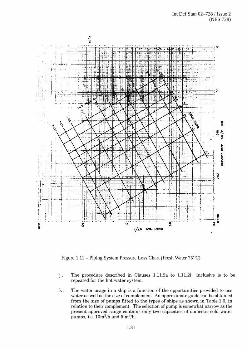
Int Def Stan 02–728 / Issue 2(NES 728)
1.31
Figure 1.11 – Piping System Pressure Loss Chart (Fresh Water 75°C)
j . The procedure described in Clauses 1.11.2a to 1.11.2i inclusive is to berepeated for the hot water system.
k . The water usage in a ship is a function of the opportunities provided to usewater as well as the size of complement. An approximate guide can be obtainedfrom the size of pumps fitted to the types of ships as shown in Table 1.6, inrelation to their complement. The selection of pump is somewhat narrow as thepresent approved range contains only two capacities of domestic cold waterpumps, i.e. 10m3/h and 5 m3/h.

Int Def Stan 02–728 / Issue 2(NES 728)
1.32
Ship Type ComplementNumber and Capacity
Fitted
Type 23 200 2 at 5 m3/h
Type 42/45 260/313 2 at 10 m3/h
Assault Ships 600 + 300 `Troops' 4 at 10 m3/h
CVS 970/980 4 at 10 m3/h
CV(F) 1000 Total (Approx) 4 at 10 m3/h
Table 1.6 – Example of Pump Fits
l . In ships of Frigate/Destroyer size and above, two pumps are normally to beprovided for each group of storage tanks. In ships below Frigate/Destroyer size,one pump is to be provided for each group of storage tanks. At least two pumpsare to be provided. The pumps are to be identical.
m . Very roughly it can be said that ships with a complement of say, 250 and underwill be fitted with two 5 m3/h pumps. Ships with a complement of, say 250 to500 will be fitted with two 10 m3/h pumps and ships with a complement over 500will be fitted with four 10 m3/h pumps.
1.11.3 Review of General Design
a . Because of the averaging and diversifying factors used in the initial and finaldesign it is necessary for a general review to be made to ensure that these havenot led the designer into design detail which is inappropriate to the duties of thesystem. A comparison with existing designs for similar ships which are knownto be satisfactory or to have certain limitations would be advantageous.
1.11.4 Supplies to Washbasins and Showers
a . For arrangements and sizing of pipework in bathrooms see NES 120.
1.11.5 Diversity Factors for Outlets
a . Because of the large flow involved it is not feasible or desirable to design thesystem for all water outlets being in full use at one time.
b . The system is to be designed on the basis that the normal percentage of outletsthat would be in use at any time will be as shown on Figure 1.12, ignoringoutlets which are not in daily use, e.g. decontamination supplies, emergencysupplies to sonar cooling equipment, etc. Figure 1.12 is basically intended forapplication to bathroom outlets but it is to be used, in the absence of moreobvious ratios, for all multiple outlets.
c . The diversity factor as applied to any point in the system relates to the numberof outlets downstream of that point. The diversity factor thus decreases asconsideration moves from the branch extremities towards the pumps.
d . Certain outlets of a specialist nature may require a large water quantity at aspecific pressure. The incorporation of such equipment in the system willnecessitate modification of the method of calculating diversity factor.
e . For economic reasons, to obtain the limits of discharge for the various outletsthe sizes that are to be fitted are shown in Table 1.7. The flow from showersgiven is to be taken as being provided 50% from the hot water system and 50%from the cold water system.

Int Def Stan 02–728 / Issue 2(NES 728)
1.33
FittingSize of Outlet Flow Rate
Fitting(mm) (m3/h)
Window washer 6 0.07
Washbasin/tap 10 0.27
Shower head 13 0.27
Tap 13 0.57
Tap 19 1.63
Tap 25 3.34
Table 1.7 – Discharge Rate for Fittings
1.11.6 Cold Water Pump
a . The capacity of the cold water pumps are to be adequate to pass the diversifiedflow, ignoring outlets which are not in daily use.
b . The pressure developed is to be the system calculated pressure drop, Annex D.Data Sheet D4/- plus 10% plus 0.35 bar. This pressure may need to beincreased if there is a specific requirement for a pressure in excess of 0.35 bar forequipment at high level, e.g. bridge window washers 1.4 bar, see Clause 1.3.1d .
c . The pump may now be selected, see Clause 1.7.
d . The pump discharge pressure at zero flow from a full storage tank is to beobtained from the pump performance characteristic. This will be the maximumworking pressure of the system.
e . In Submarines where the cold water system is pressurized by air and not by coldwater pumps, the calculated pressure drop, Annex D. Data Sheet D4/- plus0.35 bar is to be the normal working pressure of the air in the FW storage tanks.

Int Def Stan 02–728 / Issue 2(NES 728)
1.34
Figure 1.12 – Diversity Factor: Number of Fittings Connected
This graph shows the normalpercentage of fittings thatmight be in use at any onetime.
1.11.7 Cold Water Boost Pump
a . Where the total static head exceeds 4 bar or 90% of the maximum head availablefrom the cold FW pump selected, whichever is the lower, a boost system,supplied by a continuously running pump, is to be provided to serve the higheroutlets. The limit of 4 bar has been selected to prevent lower outlets from beingsubjected to unduly high pressures. The limit of 90% of the maximum headavailable from the cold FW pump provides a 10% margin between headavailable and required to allow for any errors in calculation.

Int Def Stan 02–728 / Issue 2(NES 728)
1.35
b . The most convenient point to install the boost pump is to be selected, so as to beclose to the maximum demand on the boost circuit and to suit the ship'sarrangement. Note that the bridge window washers are likely to be on thiscircuit. The point selected is to serve all outlets on the top decks and is to besuitable for use with either cold water pump operating. The most suitable pointwill probably be in the main branch to the top decks. If more than one branch isproposed, consideration is to be given to re�arranging the piping to provide onemain branch to the top deck, to installing more than one boost system or toproviding a main feed from boost pumps at each end.
c . When it is decided that a cold water boost pump is to be installed then thedifferential head necessary from the cold water pump is to be re�assessed toallow for the lower static lift required.
d . The minimum differential head necessary from the boost pump is to bedetermined by adding 0.35 bar to the maximum total head loss for the sectionsupplied by the boost pump.
1.11.8 Pressure at Outlets
a . Once the pump pressure is known, the minimum pressure expected at alloutlets under design flow conditions is to be established in turn. As a generalrule, where the pressure at an outlet is in excess of a gauge pressure of 2 bar inthe cold and hot water systems, consideration is to be given to reducing thepressure first by re�calculating for smaller pipes. Use of smaller pipes meanssaving in weight, cost and size of fittings as well as piping. Severalre�calculations for pipe size may be advantageous, subject to the limitationsthat the general water velocities do not exceed those given in Table 1.4 and thatthe minimum pipe bore is not less than 13 mm diameter in the main system ormain branches. In Submarines higher speeds will be accepted where spacelimitation demands the fitting of smaller bore pipework. It will be noted thatapplication of the pipe sizes given in NES 120 for washbasins and showersautomatically keeps the water speeds in these areas below the limiting speedsgiven in Table 1.4.
b . If it is not possible to reduce the pressure by the above method, orifice plates ofbrass or nylon are to be fitted to the connections to all washbasin taps andshower head fittings, etc, to limit the outlet pressure to 2 bar and the flow ratesto the quantities given in Table 1.7. Fitting the orifice plate to the connections(see Figure 1.13) makes the orifice plate peculiar to the system and permits astandard tap or shower head to be fitted. The size of orifice plate installed is tobe selected from the preferred range shown in Table 1.8.
Int Def Stan 02–728 / Issue 2(NES 728)
1.36
Figure 1.13 – Washbasin Taps and Shower Head Fittings – Fitting of Orifice Plates
Pressure in Main (bar) Size of Orifice (mm)
over 3 2.5
2 to 3 3.0
Table 1.8 – Range of Orifice Plates
1.11.9 Hot Water Circulation
a . Hot water is to be circulated round the ring main so as to ensure that thetemperature drop at any branch does not exceed about 5°C during periods oflow demand.
b . It is possible to maintain adequate circulation by natural thermo�syphon actionwhen the system resistance is low in relation to the vertical height of the flowand return legs. Table 1.9 may be used to determine if natural thermo�syphonis possible.
Pipe Size ofRing Main
(mm)
Maximum Equivalent Length of Ring Main ForEach 1 m Vertical Lift of Hot and Cold Legs
(including allowance for Valves, bends, etc) (m)
28 20
35 25
42 30
54 45
Table 1.9 – Conditions for Thermo-Syphon

Int Def Stan 02–728 / Issue 2(NES 728)
1.37
c . For compact systems on one deck, serving for example the galley anddependencies or a group of washplaces, it may be possible to omit the use of acirculating pump if the draw�off is reasonable when the system is used after aperiod of no demand. Otherwise, a hot water circulating pump is to be fitted tomaintain the ring main at the required temperature and pressure.
d . The pump selected may be capable of circulating flows in excess of thecalculated circulation. Therefore, a check is to be made to ensure that theelectric motor supplied with the circulating pump will not be overloaded whenthe pump runs out on its characteristic.
1.11.10 Selection of Calorifier
a . Consideration is to be given to the type of energy to be supplied to thecalorifiers, as to whether it should be electric or steam or duplicated by both or amixture of both. The decision will depend largely upon the design of theauxiliary energy equipment on the ship but in addition the following pointsneed to be considered:
(1) A steam control system can be modulated smoothly whereas electricallyheated calorifiers impose step load changes on the power supply.
(2) The hot water temperature in a steam calorifier will be more smoothlymaintained than that in electrically heated units in which a `cut�in' and`cut�out' hysteresis is associated with the dividing of the heating duty intoconvenient steps.
(3) On steam heated calorifiers the full load heating capacity may beuncertain by design and by installation reasons because of lack of `typetesting' of some particular designs and because the steam pressure at thecalorifier is often significantly below the calorifier design steam pressure.With electrically heated calorifiers the maximum available heat isdefinite.
b . The total number of calorifiers installed in the ship are to have a capacity of0.77 kW per person of complement. This is equivalent to a hot water flow of0.012 m3/hour for each person with the water temperature raised from 10°Cto 65°C.
c . For steam heated calorifiers provided that the total output of the calorifier tothe water is specified, the manufacturer will arrange for the heat input to coverthe surface heat emission. It is necessary to allow for the surface losses fromelectrically heated calorifiers and the piping system. However, these losses aresmall and unless the calorifier rating is close to the required rating the lossescan be ignored. Table 1.10 gives the loss per metre run of normally insulatedpipe for use when it is decided to calculate the heat losses.
Pipe Size
(mm)
Rate of Heat Emission
(W/m run)
Initial Rate of Temperature Drop(°C/h)
15 7.1 45.3
22 8.9 25.0
28 10.4 17.2
35 12.2 12.9
42 13.9 9.9
54 16.8 7.2
Table 1.10 Hot Water Piping Heat Emission and Temperature Drop

Int Def Stan 02–728 / Issue 2(NES 728)
1.38
The values given show the rate of heat release and of drop of temperature ofwater at 77°C in pipes insulated with 19 mm rigid plastic foam (Thermalconductivity 2.3 ��10-5 kW/m°C) in an ambient of 15°C and minimal flowrate.
1.11.11 Hot Water System Peak Load
a . When the heating capacity of calorifiers is sized on the basis given inClause 1.11.10b , `peak' demands on the system in excess of this requirementwill arise. It will not be possible to cater for every `peak' heat load which canarise on the hot water system. The `peak' demands for hot water are to becatered for by storage capacity which is normally to be combined with thecalorifier units. Such `peaks' of hot water are caused by the maximum usage ofbathrooms when all ship's complement want to wash/shower at the same time.
1.11.12 Hot Water Storage Capacity
a . The storage capacity required is to be sufficient to ensure that the `peak'demand described in Clause 1.11.11a can be met over a period of 60 minuteswithout the water temperature falling from an initial 65°C to below 50°C.
b . The minimum capacity is to be 0.114 m3 for small bathrooms or groups offittings, the maximum capacity being 0.455 m3.
c . When sizing a calorifier for a particular duty the capacity should be determinedafter discussion with the supplier and investigation of the space available. Forsystems where the duration and magnitude of the peak hot water load is knownthe required storage capacity can be estimated by interpolation fromFigure 1.14 to Figure 1.18 inclusive. These curves show the variation of hotwater outlet temperature with time in various conditions and are based uponthe following controlling factors:
(1) Heat input maximum (kW) = 20, 50, 100, 250, 300, 350 and 400;
(2) System pipe capacity is 0.136 m3;
(3) Calorifiers storage capacity (m3) = 0.023, 0.27, 0.45, 0.91;
(4) Cold water is supplied at 10°C;
(5) Initial water temperature in the calorifier is 65°C;
(6) Circulation around the system is at 1.36 m3/h;
(7) Hot water outlet rate (m3/h) = 0.23, 0.45, 0.91, 1.36, 1.82, 2.73, 3.41, 3.63,4.55, 6.82, 9.1.
d . To produce curves for all of the above combinations of heat input, water outletrate and storage capacity would result in an excessive number of graphs. Thecurves plotted were, therefore, kept to a minimum but the curves selected aresufficient to ensure that an adequate comparison can be made for othercombinations of heat input, water outlet and storage capacity considered butfor which curves have not been produced. To achieve this, graphs wereproduced with a selection of curves where the water temperature is maintainedabove 60°C throughout plus a selection where the water temperature dropsbelow 60°C within 60 minutes. From these curves it can be determined forother combinations of heat input, water outlet rate and storage capacitywhether or not a water temperature of 60°C is maintained after 60 minutes.

Int Def Stan 02–728 / Issue 2(NES 728)
1.39
e . The curves are arranged as follows:
(1) Figure 1.14 - This indicates the hot water temperature against time fora storage capacity of 0.023 m3 and enables interpolation to be made forcombinations of head input from 20 to 100 kW and water outlet rate from0.23 m3/h to 1.36 m3/h.
(2) Figure 1.15 - This indicates the hot water temperature against time fora storage capacity of 0.27 m3 and enables interpolation to be made forcombinations of head input from 20 kW to 100 kW and water outlet ratefrom 0.23 to 1.36 m3/h.
(3) Figure 1.16 - This indicates the hot water temperature against time fora storage capacity of 0.455 m3 and enables interpolation to be made forcombinations of heat input from 20 kW to 400 kW and water outlet ratefrom 0.23 to 0.1 m3/h.
(4) Figure 1.17 - This indicates the hot water temperature against time fora storage capacity of 0.91 m and enables interpolation to be made forcombinations of heat input from 250 kW to 400 kW and water outlet ratefrom 3.41 to 9.1 m3/h.
(5) Figure 1.18 - This indicates the effect of changing the storage capacity.To provide similar information for all heat inputs and hot water outletswould necessitate a large number of curves. Figure 1.18 has thereforebeen drawn for a heater input of 100 kW and a water outlet of 0.91 m3/hmerely to illustrate the value of changing the storage capacity.
NOTE It should be recognized that the capacity of the cold water pumpmay also be a limiting factor should a peak hot water demandcoincide with a general peak demand. In these circumstancescertain limitations may have to be tolerated.

Int Def S
tan 02–728 / Issue 2(N
ES
728)
1.40
Figure 1.14 – H
ot Water Tem
perature From
Calorifier: T
ime for a S
torageC
apacity of 0.023 m 3
At each curve:
Maximum heating input shown in kWWater outlet rate shown in m3/h
50 kW/1.36 m3/h
20 kW/0.455 m3/h
50 kW/0.91 m3/h
100 kW/1.36 m3/h50 kW/0.455 m3/h
20 kW/0.23 m3/h
Storage Capacity 0.023 m3
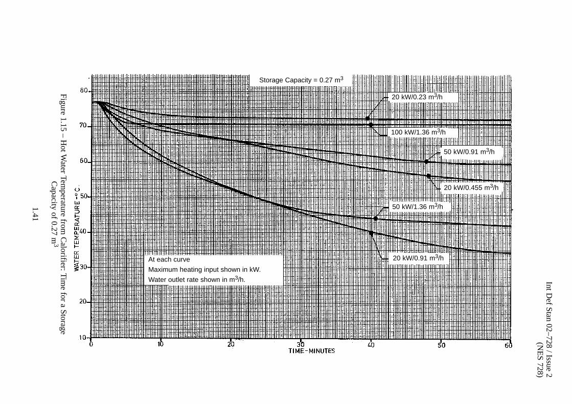
Int Def S
tan 02–728 / Issue 2(N
ES
728)
1.41
Figure 1.15 – H
ot Water Tem
perature from C
alorifier: Tim
e for a Storage
Capacity of 0.27 m 3
50 kW/1.36 m3/h
20 kW/0.91 m3/h
50 kW/0.91 m3/h
100 kW/1.36 m3/h
20 kW/0.23 m3/h
20 kW/0.455 m3/h
Storage Capacity = 0.27 m3
At each curve
Maximum heating input shown in kW.
Water outlet rate shown in m3/h.

Int Def S
tan 02–728 / Issue 2(N
ES
728)
1.42
Figure 1.16 – H
ot Water Tem
perature from C
alorifier: Tim
e for a Storage
Capacity of 0.455 m 3
For each curve number
Maximum heating input shown in kW
Water outlet rate shown in m3/h.
1. 20 kW/0.455 m3/h 7. 350 kW/6.82 m3/h
2. 50 kW/0.91 m3/h 8. 50 kW/1.36 m3/h
3. 100 kW/2.73 m3/h 9. 100 kW/3.41 m3/h
4. 400 kW/6.82 m3/h 10. 400 kW/9.1 m3/h
5. 150 kW/3.41 m3/h 11. 150 kW/3.64 m3/h
6. 250 kW/4.55 m3/h 12. 20 kW/0.91 m3/h
1
23 4
5 6 789
10
11
12
Storage Capacity = 0.455 m3

Int Def S
tan 02–728 / Issue 2(N
ES
728)
1.43
Figure 1.17 – H
ot Water Tem
perature from C
alorifier: Tim
e for a Storage
Capacity of 0.91 m 3
Storage Capacity = 0.91 m3
250 kW/3.41 m3/h
400 kW/6.82 m3/h
250 kW/4.55 m3/h
350 kW/6.82 m3/h
400 kW/9.1 m3/h
At each curve
Maximum heating input shown in kW.Water outlet rate shown in m3/h.

Int Def Stan 02–728 / Issue 2(NES 728)
1.44
Figure 1.18 – Hot Water Temperature: Time Effect of Change in Storage Capacity
Sto
rage
Cap
acity
sho
wn
in m
3
0.45
5 m
3
0.27
m3
0.02
3 m
3
Hea
t in
put
= 1
00 k
W,
Wat
er o
utle
t =
0.91
m3

Int Def Stan 02–728 / Issue 2(NES 728)
1.45
1.11.13 Electric Water Heaters
a . Isolated positions which cannot conveniently be served by the hot water systemare to be supplied by individual electric water heaters. Individual electric waterheaters are also required in medical compartments for emergency use(see Clause 1.8.3b ).
1.11.14 Accumulator for Thermal Expansion
a . The accumulator is to be designed to absorb, without significant increase insystem pressure, the increase in volume when the water in the hot water ringmain is heated between an arbitrarily chosen 54°C and the thermostaticallycontrolled limit of 70°C during zero discharge. (See NES 329).
b . An increase from say 10°C to 70°C will arise very infrequently and would beassociated with an excessively large accumulator. This condition will not becatered for by the accumulator but will be left to the calorifier relief valve.
c . The volume of water contained in the hot water ring main is to be assessed andadded to the known storage capacity of the calorifier. The increase in volumedue to this total volume expanding thermally from 54°C to 70°C is to becalculated. This is the volume to be absorbed by the accumulator.
d . Table 1.4 gives the weight of water in 1 m length of pipes of various bores used inhot water systems.
e . The accumulator separator bag is to be pre�charged with air to a pressure (P1)equal to the maximum zero flow discharge pressure of the cold water pump (iethe hot water system maximum working pressure). In absorbing the increase involume the pressure in the accumulator is to be allowed to rise by 1.4 bar. Theupper pressure (P2) therefore equals P1 + 1.4 bar. The 1.4 bar increase isspecified on the basis that the calorifier relief valve is specified to commence tolift at this point.
f . The required capacity of the accumulator is to be approximately 5% of the totalhot water system capacity, including calorifier.
1.11.15 Provision for Air Removal
a . For the satisfactory operation of the FW systems provision must be made for theremoval of air in the system which collects at high points, either because it hadbeen in the water of the system or because it was not cleared out of the systemduring the initial fill.
b . FW systems are to be provided with the following:
(1) Air bleed positions at every high point of the system. Each of these is toconsist of a pipe boss to which is fitted either an air bleed cock, or a lengthof piping with the bleed cock at its end in an accessible position;
(2) A number of air collecting vessels, in addition to the requirements of (1).These operate by reducing locally the water velocity to one�quarter of itsnormal value, which permits air closely mixed with the water or insolution to separate and collect at the top of the vessel, from which point itmay be drawn off.
c . Air collecting vessels should be fitted in horizontal pipes of the largestconvenient size, subject, for space reasons to a maximum of 54 mm pipe size.They may be fitted in either flow or return pipes, as convenient.

Int Def Stan 02–728 / Issue 2(NES 728)
1.46
d . Figure 1.19 shows a typical air collecting vessel arrangement. Requirementsfor automatic air release units are given in Clause 1.10.4a .
Drain Pipe See Figure 1.20 and Figure 1.21
Figure 1.19 – Typical Air Collecting Vessel
Air Collecting Vessel
Water Main
2D min2D
D 2D
4 D
NOTE: Dimensions 2 D are not to be greater than 100 mm
e . Figure 1.20 and Figure 1.21 show the arrangements for installing air collectingvessels with manual and automatic air release.
Figure 1.20 – Air Collecting Vessel and Manual Air Release
8 mm OD Tube
Isolating Valve Type 541,Ermeto Drg. No. 54108 ABNSN 4820–99–526–6397 (0241)
10 mm Bore 1/2–inch BSPpart of Air Collecting Vessel
Pipe to be led to suitable,clearly visible drain position

Int Def Stan 02–728 / Issue 2(NES 728)
1.47
Figure 1.21 – Air Collecting Vessel and Automatic Air Release
8 mm OD Tube
Isolating Valve Type 541,Ermeto Drg. No. 54108 ABNSN 4820–99–526–6397 (0241)
10 mm Bore 1/2–inch BSPpart of Air Collecting Vessel
Pipe to be led to suitable,clearly visible drain position
Air Eliminator Type E/AWinn and Co.Drg. No. 46896 or 44533
3/8–inch BSP
1.12 Installation and Testing
1.12.1 General
a . Flexibility is to be built into the systems to absorb the movement of the hull innormal and heavy sea conditions and to cater for possible changes intemperature of the hot water system.
1.12.2 Piping Installation
a . Piping is to be arranged in a neat and orderly manner, and as short as possibleconsistent with the design requirements for access, flexibility and ease ofmaintenance. Wherever possible flanges and fittings in parallel systems are tobe staggered.
b . Piping is to permit free passage in the walkways and working spaces and permitmaintenance of the ship's structure.
c . Piping is to be arranged to allow for the full thickness of the thermal insulationas required by NES 703.
d . Straight lengths of piping between bulkheads, decks or anchor points are to beavoided.
e . All piping is to be readily accessible throughout its length and arranged not torestrict headroom and as follows:
(1) Clear of bulkhead stiffeners, deck beams and plating butts and seams toallow for shock movement and maintenance;
(2) Clear of the underside of hatch openings to avoid being used forhandholds;
(3) Not to encroach on equipment removal routes, see NES 302.

Int Def Stan 02–728 / Issue 2(NES 728)
1.48
f . Deck and bulkhead pieces, conforming to BR 3013(2), are to be fitted wherepipes pass through watertight structures. Any flange connection necessary tothe structure is to be entirely independent of the pipe joint. Jointing flanges ofpipes passing through decks are to be so arranged that they are at least 150 mmclear of the deck.
g . Joints are to be positioned to facilitate access, removal of machinery andequipment.
h . Joints are to be arranged so that any leakage will not damage equipment orconstitute a hazard or endanger personnel.
i . Where practicable, piping layouts are to be designed to permit shop fabrication.In such designs an adequate number of closing lengths are to be incorporated.Closing lengths are to be made to a template.
j . Where a pipe is to be connected to a valve or fitting, a suitable connection or ringflange (see Clause 3.8.2.2a ) is to be fitted to the pipe to interface with the valveor fitting.
k . Straight piping of at least six diameters in length is to be provided downstreamof all turbulent raising equipments, e.g. throttling valves, bends, tees, etc.
l . Where high and low points are unavoidable, vents and drains are to be provided.
m . Wherever practicable, pipes are not to pass through electrical spaces such asdistribution centres or compartments containing switchboards, electroniccubicles and other large non�watertight electrical equipment. When this is notpossible the piping is to have no joints or valves within the compartment.Should it be essential to have a valve or joint in the compartment, agreementmust be obtained as to the acceptable arrangement and siting of deflectors,shields and/or drip trays necessary to protect the equipment from leaks and/orsprays.
n . Pipes are to be cased in where required and adequately stayed.
o . The design of the pipe supports is to be in accordance with BR 3021. Thenumber of supports is to prevent excessive vibration but should not restrain thepipes so as to cause excessive transfer of load from the structure to the pipe.
p . Where pipes are attached to structure likely to be affected by gunblast, the pipehangers are to be closely spaced and well secured on structural members ie deckbeams or girders, not on deck panels.
q . Supports are to be installed for fittings and heavy valves to prevent their weightbeing supported by the attached piping.
r . Adequate clearance is to be provided to allow for designed deflection of systemcomponents under shock. Due account should be taken of the deflection of thesupporting structure and other equipment under the shock load.
s . Pipework adjoining flexible assemblies is to be supported as close as possible tothe flexible pipe. The supports are to be installed to prevent such misalignmentof the flexible assembly as to cause the transmission of excessive forces to theconnected machinery.
t . In piping systems the straight portion is to be worked as far as possible instandard lengths, convenient for dismantling.

Int Def Stan 02–728 / Issue 2(NES 728)
1.49
u . Bends in pipes are to conform to the requirements of Clause 3.9.4b . Short stiffbends are to be avoided, particularly in positions likely to be subjected tovibration.
v . Copper pipes are to be kept clear of aluminium alloy structure. At least 12 mmis to be provided between the pipes or the pipe insulating material and thestructure.
w . Non�ferrous piping is not to be fitted into any part of the ship so low as to comeinto contact with bilge water.
1.12.3 Fresh Water Tank Calibration
a . The FW tanks are to be calibrated in tonne either by filling with a knownquantity of water or by calculation. The required method will be stated in theSTR.
b . The results are to be tabulated and the capacity curves, showing the capacity intonne against depth, forwarded to DPA.
c . Calibration index plates of nickel silver are to be supplied and fitted at eachsounding position except where Clause 1.6.3.2e applies. The followinginformation is to be engraved on each plate:
(1) Contents of the tank in tonne and decimals of a tonne corresponding tothe soundings in metres and millimetres;
(2) The distance of the water surface below the top of the sounding tube whenthe tank is 95% full, to be engraved in red.
1.12.4 Pressure Tests
a . The pressure to which the systems are to be designed is the shut valve pressureof the pumps, i.e. the maximum working pressure.
b . The various parts of each installation are to be tested during manufacture totwo times the maximum working pressure and after installation onboard to oneand a half times maximum working pressure.
c . The MOD Project Representative is to be informed when pressure tests will becarried out during manufacture so that representation can be arranged ifrequired. Similarly, the MOD Project Representative is to be notified when allpressure tests are carried out on board.
d . Clean FW is to be used for all tests during manufacture and after installationonboard.
e . Test pressures are to be maintained for periods decided by the InspectingAuthority as adequate to permit a thorough and complete inspection of all partsfor leaks. Test pressures are to be maintained for at least 30 minutes.
f . Shop pressure tests are to be carried out after all welding or brazing andmachining has been completed with all holes for securing the insulation drilledand before paint, insulation or covering of any kind has been applied. The testsafter installation may be carried out with insulation in place, but the joints ofpipe flanges, connections and valves are to be uncovered.
g . Any equipment that may be opened up after the manufacturer's shop testsmust be re�tested to shop or installation test pressure as appropriate to showthat it functions correctly after re�assembly.

Int Def Stan 02–728 / Issue 2(NES 728)
1.50
h . Parts tested are to be clearly stamped or etched or, where special materials areinvolved, painted by the manufacturer with his identification mark, the testpressure and the date of the test.
1.12.4.1 Valves
a . All valve bodies are to be tested to twice the working pressure. After assemblyall valves are to be tested to the working pressure with the valve half open to testthe gland. All except ball valves are then to be tested closed with one and a halftimes working pressure on the inlet side of the valve. Valves which may admitpressure from either side in service, except ball valves, are to have the testpressure applied independently on each side. Ball valve seats are to be tested toworking pressure only for freedom from seat leakage as the design of thesevalves is such that an increase in pressure ensures a tighter seal and thereforethe lower pressure is more critical.
b . For ball and butterfly valves, directly on completion of the tests above, at leastone in five of production batch is to be air bubble tested from 0.35 bar to 0.7 baron each seat independently; no leakage is to occur.
c . All valves are to be suitable for a working pressure of 12 bar and the testpressure is to be based on this figure irrespective of the working pressure of thesystem.
1.12.4.2 Fresh Water Tanks
a . Tanks are to be tested as follows:
(1) In Surface Ships to the pressure given in NES 155 for a period of72 hours;
(2) In Submarines the tanks are to be tested in accordance with therequirements of the STR.
1.12.4.3 Pipework in Submarines
a . In addition to the requirements of Clause 1.12.4b , any section of piping insidethe containment boundary may require to be tested to the containmentpressure, depending on the system arrangement and the requirements in theSTR.
1.12.5 Trials
a . Trials are to be carried out to demonstrate the correct functioning of thesystems in accordance with NES 366 Parts 1 and 2. A minimum pressure of0.35 bar is to be available at the outlet most remote from the pumps when thesystem is operating at full load. Additionally, a pressure of 1.4 bar is to beavailable at the Bridge Window Washer Systems.
1.12.6 Insulation
a . Thermal insulation, conforming to NES 703 is to be applied to cold FW pipingwhere it passes through store rooms and accommodation spaces, over electricalequipment and in any other location where condensation is unacceptable. HotFW piping is to be insulated with the exception of that stated in Clause 1.12.6b .
b . All FW piping on the surface of the lining in cabins, washplaces and showers isnot to be insulated. In Submarines, piping behind linings is not to be insulated.

Int Def Stan 02–728 / Issue 2(NES 728)
1.51
1.12.7 Colours and Marking
a . FW piping systems are to be identified with pressure sensitive identificationtapes conforming to NES 853 Part 1 for Surface Ships and NES 853 Part 2 forSubmarines.
b . All pipes of 25 mm OD and above (including insulation, if fitted) are to beidentified by stencilled system code letters as follows:
(1) Cold FW system FWC
(2) Domestic Hot FW FWH
c . All pipes of less than 25 mm OD (including insulation, if fitted) are to beidentified by colour banding. The pipe coupling is to be painted MiddleBrunswick Green (BS 381C colour No 226). The length of pipe 150 mm eachside of this coupling is to be painted Azure Blue (BS 381C colour No 104). Valvelevers are to be painted Azure Blue. Where there are no pipe couplings 50 mm ofpiping is to be painted to represent the coupling and 150 mm each side of thisband is to be painted with pipe colouring.
d . The colour banding of pipes is to be kept to a minimum, being used only forlengths of pipes which cannot be easily identified by other means, e.g. valvelevers or near attachments to readily identifiable machines or equipment.

Int Def Stan 02–728 / Issue 2(NES 728)
1.52
Int Def Stan 02–728 / Issue 2(NES 728)
2.1
2. NATIONAL/INTERNATIONAL REGULATIONS
Related Documents: BS 381C, BS EN ISO 1461; see also Annex A.
2.1 Materials
2.1.1 Material Selection
a . Pipe clips are to be of steel, galvanized in accordance with BS EN ISO 1461 (seealso Clause 1.12.2o ).
b . All items used in the construction of Ships FW systems should be of types thatdo not provide a habitat for bacteria.
2.1.2 Fresh Water Storage Tanks
a . Access ladders inside storage tanks are to be of steel, galvanized in accordancewith BS EN ISO 1461.
2.2 Installation
2.2.1 Colours and Marking
a . All pipes of less than 25 mm outside diameter (including insulation, if fitted) areto be identified by colour banding. The pipe coupling is to be painted MiddleBrunswick Green (BS 381C colour No 226). The length of pipe 150 mm eachside of this coupling is to be painted Azure Blue (BS 381C colour No 104). Valvelevers are to be painted Azure Blue.

Int Def Stan 02–728 / Issue 2(NES 728)
2.2

Int Def Stan 02–728 / Issue 2(NES 728)
3.1
3. MILITARY STANDARDS/REQUIREMENTS
Related Documents: BS 864; BS 1387; BS 1706; BS 3382 Part 2; BS 3602 Part 1;BS 3692; BS EN 10028–1, 2 and 4; NES 101; NES 102; NES 107; NES 106; NES 107;NES 112; NES 118; NES 119; NES 120; NES 121; NES 123; NES 155; NES 302;NES 309; NES 327; NES 328; NES 329; NES 341; NES 360; NES 703; NES 706; NES707; NES 710; NES 722; NES 729 Parts 1 to 5; NES 743 Part 1, 4 and 5; NES 745 Parts 1and 2; NES 748; NES 763; NES 769; NES 771; NES 773; NES 791; NES 797; NES 830Part 1; NES 833 Part 2; NES 837; NES 1018 Part 1; NES 1032 Parts 1 to 4; BR 820;BR 2170; BR 3013(2); BR 3013(2) Part 2; BR 3021; DG Ships/G/10000B; see alsoAnnex A.
3.1 Drawings
3.1.1 System Drawings
a . All drawings are to conform to the requirements of NES 722.
b . Drawings to be supplied by the Shipbuilder will be defined in the STR.
c . Equipment drawings are to be supplied by the equipment manufacturer (seeClause 1.1.3a ).
d . Each pipe system covered in this NES for which drawings are required will bespecified in the STR. Drawings are to be based on any associated DPA guidancedrawings.
3.1.2 System Diagrammatic Arrangement Drawings
a . Symbols used are to conform to NES 707.
3.2 Materials
3.2.1 Material Selection
a . Any proposals to use new materials not specified in this NES are to besubmitted to DPA for approval.
b . Gunmetal is only to be used in Submarines with the specific approval of DPA.
3.2.2 Fresh Water Storage Tanks
a . Where constructed independent of the hull structure, storage tanks are to be ofsteel complying with NES 791.
3.2.3 Pumps
a . Materials for rotary pumps are given in NES 327.
3.2.4 Calorifiers
a . Materials for calorifiers are given in NES 329.
3.2.5 Non-ferrous Pipework
a . All FW piping except that specified in Clause 1.2.5a is to be of copper (6 bar,200°C maximum temperature), to NES 837. Connections and flanges are to beof gunmetal to NES 830 Part 1 (see BR 3013(2), Part 2) except whereClause 1.2.1b applies.

Int Def Stan 02–728 / Issue 2(NES 728)
3.2
3.2.6 Steel Pipework
a . Sounding tubes, air escapes and sections of suction pipes within fresh watertanks are to be carbon steel complying with BS 3602, Part 1, Hot FinishedSeamless (HFS Grade 360) or Cold Finished Seamless (CFS Grade 360),galvanized internally and externally. Connecting sleeves and ring flanges are toto be of galvanized steel complying with BS EN 10028-1/2 (see BR 3013(2),Part 2).
3.2.7 Valves
a . Materials for valves are given in NES 360.
b . Push cocks for supply to cabin, bathroom, workshop and office washbasins,mess draw�off, etc, are to be of chrome�plated brass.
3.2.8 Screwed Fasteners
a . Materials for screwed fasteners are to be:
(1) High tensile aluminium bronze complying with NES 833 Part 2 fornon�ferrous pipes and fittings only;
(2) Steel complying with BS 3692, zinc plated in compliance with BS 3382,Part 2, for diameters up to M18 and BS 1706, Zn3 for diameters aboveM18 for ferrous pipes and fittings.
3.2.9 Jointing
a . Jointing rings are to be of rubberized cork in accordance with BR 3013(2).Jointing paste is not to be used.
3.2.10 Insulation
a . Thermal insulation is to conform to NES 703.
3.3 System General Requirements
3.3.1 General
a . Domestic hot and cold FW systems are to be designed to meet the followingMilitary requirements:
(1) To ensure that the system will provide and maintain the required degreeof cold water purity in service as specified in BR 820;
(2) To meet zoning requirements laid down in NES 119;
(3) The systems are to be designed to conform to the requirements ofNES 710 and NES 797.
3.3.2 Cold Water System, Services Supplied
3.3.2.1 Surface Ships
a . Compartments and services in Surface Ships to be supplied with cold FW willinclude:
(1) Bathrooms, Water Closets (WC) and Urinals, see NES 120;
(2) Dining Halls, see NES 107;
(3) Galley and associated compartments, see NES 121;
(4) Laundries and laundry equipment, see NES 123;
(5) Medical and Dental spaces, see NES 106;
(6) Other compartments fitted with washbasins, see NES 120, includingcabins, see NES 107, and selected workshops, see NES 101;

Int Def Stan 02–728 / Issue 2(NES 728)
3.3
(7) Gas Turbine compressor washing tanks, see NES 309;
(8) Desalination plant servicing positions, see NES 328;
(9) Torpedo test and assembly magazine, see NES 1018;
(10) Citadel cleansing stations, see NES 118;
(11) Bridge Window Washer Systems, see NES 112;
(12) NBCD section bases, see NES 119.
b . Cold FW for wash�down purposes is required in Surface Ships as follows:
(1) Bathrooms, WC and urinals, see NES 120;
(2) Galley, see NES 121;
(3) Laundries, see NES 123.
3.3.3 Hot Water System, Services Supplied
3.3.3.1 Surface Ships
a . Compartments and services to be provided with hot fresh water in SurfaceShips include:
(1) Bathrooms, WC and Urinals, see NES 120;
(2) Galleys and associated spaces, see NES 121;
(3) Laundries, see NES 123;
(4) Medical and Dental spaces, see NES 106;
(5) Other compartments fitted with washbasins, see NES 120, includingcabins, see NES 107 and selected workshops, see NES 101.
3.3.4 Provision of Washbasins and Showers
a . For scale of allowance of washbasins, showers and baths, see NES 120.
3.4 System Arrangement
3.4.1 Cold Fresh Water
3.4.1.1 Surface Ships
a . The suction pipework is to include the necessary isolating valves, non�returnvalves and a 1.5 mm diameter aperture size pump suction duplex strainer toconform to NES 748.
b . The essential services include:
(1) Medical and Dental spaces, see NES 106;
(2) Galleys and associated spaces, see NES 121;
(3) Drinking Water Coolers;
(4) Bridge Window Washer Systems see NES 112;
(5) Bathrooms used as cleansing stations, see NES 120;
(6) FW cooling to guns.
c . Flexible assemblies fitted in the system are to conform to the requirements ofNES 797.

Int Def Stan 02–728 / Issue 2(NES 728)
3.4
3.4.2 Emergency Fresh Water Supply to Sonar Cooling System
a . On some Surface Ships an emergency FW supply is required for the SonarCooling System. Hose connections with lockable valves and portable hoses toconnect between the Domestic Cold Water System and a similar connection onthe Sonar Cooling System is to be provided for the supply and similarconnections for the return between the Sonar System and the Filling/TransferMain. These connections are in accordance with the requirements of NES 102.
3.5 Desalination Requirements
3.5.1 General
a . In Surface Ships and Submarines the desalination plants are to conform to therequirements of NES 328.
3.6 Fresh Water Storage and Filling
3.6.1 Storage Tank Arrangements
3.6.1.1 Surface Ships
a . FW tanks are to be designed to the requirements of NES 1032 Parts 1 to 4.
b . Welding is to conform to NES 706.
3.7 Pump Selection
3.7.1 General
a . The information in Clauses 1.7.2 to 1.7.6 applies to pumps for Surface Shipsonly.
b . Pumps are to conform to NES 327.
c . Generally, electric motor driven self�priming centrifugal pumps are to be fittedfor the distribution of FW throughout the ship.
d . For number of pumps to be fitted, see Clause 1.11.2m.
e . For operation of pumps in NBCD State 1, see BR 2170.
3.8 Auxiliary Components
3.8.1 Accumulators
a . DPA approved accumulators are to be used.
3.8.2 Pipework
3.8.2.1 Non-Ferrous Piping
a . Lengths of non�ferrous piping are to be connected together by one of thefollowing methods:
(1) Pipe size 54 mm and below:
(a) Capillary fittings to BR 3013(2), Part 2;
(b) Screwed unions for pipe sizes up to 35 mm;

Int Def Stan 02–728 / Issue 2(NES 728)
3.5
(c) Compression fittings to BS 864, Type A for pipe sizes up to 22 mm.Fittings are to be of the non�manipulative type only. They are not tobe used in the following applications:
(i) Terminal connections to equipment likely to be broken andre�made (a capillary fitting coupling / connector isrecommended in this case);
(ii) Compartments where equipment would be damaged ifsubjected to accidental flooding or spraying, such asmagazines, electrical equipment rooms and compartmentswhich are not normally manned at sea.
(2) Pipe sizes above 54 mm are to be fitted with flanges to BR 3013(2), Part 2;
(3) For Submarines, Pipe Fabrication Charts are to be prepared by theShipbuilder and agreed with DPA.
3.8.2.2 Steel Piping
a . Lengths of steel piping are to be connected together by one of the followingmethods:
(1) Pipe sizes below 48 mm are to be fitted with screwed sleeves. Long screws,bends and springs are to conform to BS 1387, to allow for parallelscrewing;
(2) Pipe sizes 48 mm and above are to be fitted with welded ring flanges toBR 3013(2), Part 2. Flanges are to be welded prior to galvanizing. Wherespace precludes the fitting of flanges, pipes may be connected by doublewelded sleeves.
3.8.2.3 Jointing
a . Rubberized cork jointing rings are to be ordered from the manufacturer aspre�cut gaskets to the dimensions given in BR 3013(2), Part 2. Gaskets are notto be coated with jointing paste.
3.8.3 Valves
a . Valves are to be selected from the standard range given in NES 360.
b . Push�cocks for the supply to cabin, bathroom, workshop and office washbasins,mess deck draw�off, etc, are to be of the non�concussive type.
c . In Submarines all line valves are to be of the ball type.
3.8.4 Strainers
a . Strainers are to be as specified in the STR.
3.9 Manufacturing Practices
3.9.1 General
a . Meticulous attention to the standard of workmanship, finish, cleanliness andinspection throughout construction is necessary.
3.9.2 Welding
a . The requirements of the documents listed in Table 3.1 are to be followed tocover specialized application of welding. The requirements of these documentsare mandatory.
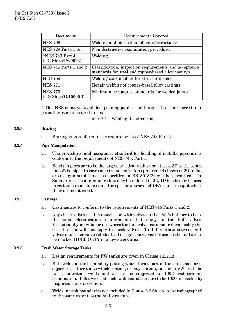
Int Def Stan 02–728 / Issue 2(NES 728)
3.6
Document Requirements Covered
NES 706 Welding and fabrication of ships' structures
NES 729 Parts 1 to 5 Non�destructive examination procedures
*NES 743 Part 4(DG Ships/PS/9023)
Welding
NES 745 Parts 1 and 2 Classification, inspection requirements and acceptancestandards for steel and copper�based alloy castings
NES 769 Welding consumables for structural steel
NES 771 Repair welding of copper�based alloy castings
NES 773(DG Ships/G/10000B)
Minimum acceptance standards for welded joints
* This NES is not yet available; pending publication the specification referred to inparentheses is to be used in lieu.
Table 3.1 – Welding Requirements
3.9.3 Brazing
a . Brazing is to conform to the requirements of NES 743 Part 5.
3.9.4 Pipe Manipulation
a . The procedures and acceptance standard for bending of metallic pipes are toconform to the requirements of NES 743, Part 1.
b . Bends in pipes are to be the largest practical radius and at least 3D to the centreline of the pipe. In cases of extreme limitations pre�formed elbows of 2D radiusor cast gunmetal bends as specified in BR 3013(2) will be permitted. OnSubmarines the minimum radius may be reduced to 2D, 1D bends may be usedin certain circumstances and the specific approval of DPA is to be sought wheretheir use is intended.
3.9.5 Castings
a . Castings are to conform to the requirements of NES 745 Parts 1 and 2.
b . Any check valves used in association with valves on the ship's hull are to be tothe same classification requirements that apply to the hull valves.Exceptionally on Submarines where the hull valve has a non�return facility thisclassification will not apply to check valves. To differentiate between hullvalves and other valves of identical design, the valves for use on the hull are tobe marked HULL ONLY in a low stress area.
3.9.6 Fresh Water Storage Tanks
a . Design requirements for FW tanks are given in Clause 1.6.2.1a.
b . Butt welds in tank boundary plating which forms part of the ship's side or isadjacent to other tanks which contain, or may contain, fuel oil or SW are to befull penetration welds and are to be subjected to 100% radiographicexamination. Fillet welds at such tank boundaries are to be 100% inspected bymagnetic crack detection.
c . Welds in tank boundaries not included in Clause 3.9.6b are to be radiographedto the same extent as the hull structure.

Int Def Stan 02–728 / Issue 2(NES 728)
3.7
3.10 Cleaning and Preservation
3.10.1 General
a . Requirements for cleaning and preservation are to conform to NES 341 andNES 763.
b . Red and white lead is not to be used in FW systems.
3.10.2 Fresh Water Storage Tanks
a . Internal surfaces of steel FW tanks are to be treated in accordance with therequirements of NES 763.
b . On completion of the coating of the inside of the tanks, they are to be sealed andnot re�entered until the requirements of Clause 3.11.3a are undertaken.
3.10.3 Tubes and Pipes
a . Copper tubes and pipes are to be cleaned and preserved after bending, brazingor welding on flanges and couplings, flange facing and drilling in compliancewith the requirements of NES 341.
3.11 Installation and Testing
3.11.1 Piping Installation
a . Piping is to be arranged to allow for the full thickness of the thermal insulationas required by NES 703.
b . All piping is to be readily accessible throughout its length and arranged not toviolate equipment removal routes, see NES 302.
c . Deck and bulkhead pieces, conforming to BR 3013(2), are to be fitted wherepipes pass through watertight structures.
d . The design of the pipe supports is to be in accordance with BR 3021.
3.11.2 Fresh Water Tank Calibration
a . The FW tanks are to be calibrated in tonne either by filling with a knownquantity of water or by calculation. The required method will be stated in theSTR.
b . The results are to be tabulated and the capacity curves, showing the capacity intonne against depth, forwarded to DPA.
3.11.3 Inspection and Flushing
a . The final cleaning of the FW storage tanks is to be carried out by men of cleanhabits wearing clean overalls and rubber shoes. The inspection of the systemsand tank coatings is to be carried out by the Shipbuilder and DPA prior to theinitial filling and flushing of the system. When the system is pronounced cleanof all swarf, etc, the tanks, filling system, circulating system and distilingsystem are to be filled with superchlorinated FW, as per BR 820. Thereafter, thesystems are to be completely drained and then refilled with clean fresh water,there being sufficient chlorine remaining in the system to make this final fillingan acceptable potable water.
3.11.4 Pressure Tests
a . The MOD Project Representative is to be informed when pressure tests will becarried out during manufacture so that he may be present if he wishes.

Int Def Stan 02–728 / Issue 2(NES 728)
3.8
Similarly, the MOD Projective representative is to be notified when all pressuretests are carried out on board.
b . Test pressures are to be maintained for periods decided by the InspectingAuthority as adequate to permit a thorough and complete inspection of all partsfor leaks. Test pressures are to be maintained for at least 30 minutes.
3.11.4.1 Fresh Water Tanks
a . Tanks are to be tested as follows:
(1) In Surface Ships to the pressure given in NES 155;
(2) In Submarines the tanks are to be tested in accordance with therequirements of the STR.
3.11.5 Insulation
a . Thermal insulation, conforming to NES 703 is to be applied to cold fresh waterpiping where it passes through store rooms and accommodation spaces, overelectrical equipment and in any other location where condensation isunacceptable. Hot FW piping is to be insulated with the exception of that statedin Clause 1.12.6b .
3.11.6 Colours and Marking
a . FW piping systems are to be identified with identification tapes conforming toNES 853 Part 1 for Surface Ships and NES 853 Part 2 for Submarines.

Int Def Stan 02–728 / Issue 2(NES 728)
4.1
4. DESIGN REQUIREMENTS/GUIDANCE
Related Documents: NES 101; NES 106; NES 107; NES 112; NES 118; NES 119;NES 120; NES 121; NES 123; NES 309; NES 328; NES 1018 Part 1; see also Annex A.
4.1 System General Requirements
4.1.1 Cold Water System, Services Supplied
4.1.1.1 Surface Ships
a . Compartments and services in Surface Ships to be supplied with cold freshwater will include:
(1) Bathrooms, WC and Urinals, see NES 120;
(2) Dining Halls, see NES 107;
(3) Drinking water coolers;
(4) Galley and associated compartments, see NES 121;
(5) Laundries and laundry equipment, see NES 123;
(6) Medical and Dental spaces, see NES 106;
(7) Other compartments fitted with washbasins, see NES 120, includingcabins, see NES 107, and selected workshops, see NES 101;
(8) Gas turbine compressor washing tanks, see NES 309;
(9) Self�cleaning centrifuge header tanks;
(10) Desalination plant servicing positions, see NES 328;
(11) Filter Cleaning Station;
(12) Battery Charging Room;
(13) Engineer's Test Room;
(14) Photographic Room;
(15) Torpedo test and assembly magazine, see NES 1018;
(16) Hangars and flight�deck aircraft service positions;
(17) Citadel cleansing stations, see NES 118;
(18) Gun mountings;
(19) Bridge Window Washer Systems, see NES 112;
(20) NBCD section bases, see NES 119;
(21) Supply to hot water system.

Int Def Stan 02–728 / Issue 2(NES 728)
4.2
b . Cold FW for wash�down purposes is required in Surface Ships as follows:
(1) Bathrooms, WC and Urinals, see NES 120;
(2) Galley, see NES 121;
(3) Laundries, see NES 123.
c . The following are possible users of cold FW in Surface Ships on an intermittentbasis:
(1) Emergency FW supply to sonar cooling system;
(2) Spraying for NBC cleansing of missile launcher hoists;
(3) Spraying for NBC cleansing of missile magazines;
(4) Cleansing stations, where not used as bathrooms;
(5) Boiler external washing;
(6) Boiler acid cleaning;
(7) Gas turbine intake filter washing;
(8) Topping�up diesel engine FW cooling systems;
(9) Filling and topping�up air conditioning chilled water system;
(10) Filling and topping�up of magazine spraying systems controlled byquartzoid bulbs;
(11) Jackson Boiler;
(12) NAAFI Vending Machines;
(13) Motor Boat filling (upper deck).
4.1.1.2 Submarines
a . For Submarine selected items listed in Clause 4.1.1.1a are applicable (whereappropriate) and main services to be supplied with cold FW will normallyinclude:
(1) Jackson Boiler;
(2) Water heaters;
(3) Flushing of Shaft Seal;
(4) Demineralizers;
(5) Pyrotechnic lockers;
(6) Sink at Oxygen Generators;
(7) Escape compartments for filling emergency drinking water storage tankssee Clause 1.9.1d.

Int Def Stan 02–728 / Issue 2(NES 728)
4.3
4.1.2 Hot Water System, Services Supplied
4.1.2.1 Surface Ships
a . Compartments and services to be provided with hot FW in Surface Shipsinclude:
(1) Bathrooms, WC and Urinals, see NES 120;
(2) Galleys and associated spaces, see NES 121;
(3) Laundries, see NES 123;
(4) Medical and Dental spaces, see NES 106;
(5) Other compartments fitted with washbasins, see NES 120, includingcabins, see NES 107 and selected workshops, see NES 101.
4.1.2.2 Submarines
a . In addition to those items listed in Clause 4.1.2.1a which are applicable toSubmarines, main services to be provided with hot FW include:
(1) Sinks, wash-basins and showers;
(2) Bibcocks;
(3) Electrostatic Precipitators.
4.1.3 Provision of Washbasins and Showers
a . For scale of allowance of washbasins, showers and baths, see NES 120.
4.2 Fresh Water Storage and Filling
4.2.1 Storage Tank Arrangement
4.2.1.1 Submarines
a . Three FW storage tanks are usually fitted in Submarines. Two of the tanksbeing for domestic FW, the other being dedicated to the weapons stowagecompartment spray system.
4.2.2 Sounding Tubes
a . Sounding tubes are not fitted in Submarines where reliance is placed onelectrical instrumentation.

Int Def Stan 02–728 / Issue 2(NES 728)
4.4

Int Def Stan 02–728 / Issue 2(NES 728)
5.1
5. CORPORATE EXPERIENCE AND KNOWLEDGE
This NES contains no Corporate Experience and Knowledge information.

Int Def Stan 02–728 / Issue 2(NES 728)
5.2

Int Def Stan 02–728 / Issue 2(NES 728)
ANNEX AA.1
ANNEX A.
RELATED DOCUMENTS
A.1. The following documents and publications are referred to in this NES:
BS 381C Specification for Colours for Identification, Coding and SpecialPurposes
BS 864 Capillary and Compression Tube Fittings of Copper and CopperAlloy:
Part 2: Specification for Capillary and Compressed Fitting forCopper Tubes
BS 1387 Specification for Screwed and Socketed Steel Tubes and Tubular andfor Plain End Steel Tubes Suitable for Welding or for Screwing toBS 21 Pipe Threads
BS 1706 Method for Specification for Alloy Steel Plates
BS 3382 Specification for Electroplated Coatings on Threaded Components:
Part 2: Cadmium on Steel Components. Zinc on Steel Components
BS 3602 Specification for Steel Pipes and Tubes for Pressure Purposes:Carbon and Carbon Manganese Steel with Specified ElevatedTemperature Properties:
Part 1: Specification for Seamless and Electric Resistance WeldingIncluding Induction Welded Tubes
BS 3692 Specification for ISO Metric Hexagon Bolts, Screws and Nuts. MetricUnits
BS EN 1461 Hot Dip Galvanized Coatings on Iron and Steel Articles.Specification and Test Methods
BS EN 10028 Specification for Flat Products Made of Steel for Pressure Purposes:
Part 1: General Purposes
Part 2: Non�alloy and Alloy Steels with Specified ElevatedTemperature Properties
Part 4: Nickel Alloy Steels with Specified Low TemperatureProperties
JSP 430 Ship Safety Management System Handbook:
Volume 1 Policy and Guidance on MOD Ship and Equipment SafetyManagement
DG Ships 9023 General Welding Specification for Machinery Purposes
DG ShipsG/10000B
Minimum Acceptance Standards for Welds in HM Surface Ships andSubmarines
NES 101 Requirements for Design and Fitting Out of Workshops MaintenanceSpaces and Engineering Stores for HM Surface Ships:
Part 1: Common Requirements
Part 2: Specific Requirements
NES 102 Requirements for Air Conditioning and Ventilation Design
Part 1: HM Surface Ships
Part 2: Submarines

Int Def Stan 02–728 / Issue 2(NES 728)
ANNEX A A.2
NES 106 Requirements for Medical and Dental Organizations inHM Surface Ships:
Part 1: Common Requirements - Medical and Dental Facilities
Part 2: Specific Requirements - Medical and Dental Facilities
Part 3: Specific Requirements - Medical Organization for Actionon HM Surface Ships
Part 4: Medical and Dental Facilities in Submarines
NES 107 Requirements for Accommodation - HM Surface Ships
NES 112 Requirements for Windows and Wipers for HM Surface Ships
NES 118 Material Requirements for the NBCD of HM Surface Ships includingRFA (Restricted)
NES 119 The Requirements for Fire Protection and Damage Control forHM Surface Ships (Restricted Commercial))
NES 120 Requirements for WC, Urinals, Bathrooms and Washing Facilities inHM Surface Ships
NES 121 Requirements for Galleys and Associated Spaces inHM Surface Ships
NES 123 Requirements for Laundries and Associated Compartments:
Part 1: Laundries and Associated Compartments
Part 2: Laundry Machinery, Equipment and Fittings
NES 155 Requirements for Structural Practices in Steel Surface Ships
Part 1: General Requirements
NES 302 Requirements for Maintenance Envelopes and Removal Routes
NES 309 Requirements for Gas Turbines (Restricted)
NES 311 Guidance and Procedures for the Calculation of Pressure Losses inFluid Piping Systems
NES 327 Pumps and Eductors
NES 328 Desalination Plants (Obsolecent)
NES 329 Heat Exchangers (Restricted)
NES 341 Requirements for Cleaning of Items, Components and Equipmentfor Fluid Systems
NES 360 List of Preferred Standard Valves - Metric
NES 703 Thermal and Acoustic Insulation of Hull and Machinery
NES 706 Welding and Fabrication of HM Surface Ships' Structure
NES 707 Symbols and Abbreviations
NES 710 Fluid Systems, General Requirements (Obsolecent)
*NES 797: Pipework Engineering
Part 1: General Requirements for Fluid Systems
NES 722 Requirements for the Preparation, Identification and Managementof Drawings

Int Def Stan 02–728 / Issue 2(NES 728)
ANNEX AA.3
NES 729 Requirements for Non�Destructive Examination Methods:
Part 1: Radiographic
Part 2: Magnetic Partical
Part 3: Eddy Current
Part 4: Liquid Penetrant
Part 5: Ultrasonic
NES 743 Pipe Manipulation:
Part 1: Bending Pipes
Part 3: Swaging
**Part 4: Welding (DG Ships/PS/9023)
Part 5: Brazing
NES 745 Classification, Inspection Requirements and Acceptance Standardsfor Castings:
Part 1: Copper and Nickel Alloy Castings
Part 2: Steel Castings
NES 748 Strainers, Preferred Range
NES 763 Requirements for Preservation and Painting of Compartments inHM Surface Ships (Restricted Commercial)
NES 769 Approval Systems for Welding Consumables for Structural Steels
NES 771 Requirements, Procedure and Inspection for Weld Repair of CopperAlloy and Nickel Alloy Castings
NES 791 Requirements for Weldable Structural Steels:
Part 1: Mild Steel Plate Sections and Bars
Part 2: Notch Tough Mild Steel Plate
Part 3: B Quality Steel Plates and Sections
Part 4: BX Quality Steel Plates
NES 797 Pipework Engineering:
Part 1: General Requirements for Fluid Systems - (see NES 710)
Part 4: Screwed Fittings
NES 830 Requirements for Gunmetal Ingots and Castings:
Part 1: Gunmetal Ingots and Class III Gunmetal Castings
NES 833 Requirements for Nickel Aluminium Bronze:
Part 2: Forgings, Forging Stock, Rods and Sections
NES 837 Requirements for Copper Tubes
NES 853 Requirements for the Identification, Colours and Markings forSystems Coding:
Part 1: HM Surface Ships (Supersedes MOD Form S1188)
Part 2: Submarines (Supersedes MOD Form S1471)
NES 1018 Requirements for Weapons Systems Support Services in HM Surface Ships and RFA (Restricted)
NES 1032 Requirements for Aviation Arrangements in HM Surface Ships(Restricted)
BR 820 Provision of Safe Potable Water for Ships and Establishments

Int Def Stan 02–728 / Issue 2(NES 728)
ANNEX A A.4
BR 2170 Ship's NBCD Manual
BR 3013(2) Admiralty Pipework Standards (Metric)
BR 3021 Shock Manual (Metric)
Note: * In course of preparation. When published will supercede stated document.** This NES is not yet available; pending publication the Specification referred to inparentheses is to be used in lieu.
A.2. The following drawings are referred to in this NES:
SDN 003 503 642 Sounding Tube, Flush Deck and Raised Fittings
SDN 003 503 703 Sounding Tube, Raised, General Arrangement
SDN 003 504 117 Fresh Water Tanks - Addition of Lime
SDN 000 819097/1-2
Fresh Water Filling Breaching Piece
SDN 000 819098/1-3
Fresh Water RAS Deck Connections and Adaptors

Int Def Stan 02–728 / Issue 2(NES 728)
ANNEX BB.1
ANNEX B.
ABBREVIATIONS, DEFINITIONS AND FORMULAE
B.1. For the purpose of this NES the following abbreviations apply:
AV&B Auxiliary Vent and Blow System
CFS Chief of Fleet Support
CV(F) Carrier Vessel (Future)
CVS Carrier Vertical Strike
DLO Defence Logistics Organisation
DPA Defence Procurement Agency
FW Fresh Water
FWC Fresh Water Cold
FWH Fresh Water Hot
HP High Pressure
LP Low Pressure
MOD Ministry of Defence
NBCD Nuclear Biological Chemical Defence
NES Naval Engineering Standard
NPSH Net Positive Suction Head
OD outside diameter
ppm parts per million
RAS Replenishment at Sea
SCC Ship Control Centre
SCOSER Standing Committee on Submarine Escape and Reserve
SDN Service Drawing Number
STR Statement of Technical Requirements
SW Sea Water
WC Water Closet
WSC Weapons Storage Compartment
B.2. For the purpose of this NES the following definitions apply:
Accumulator A vessel designed to absorb, without sufficient change in the systempressure to cause the relief valve to lift, the change in volume whenthe hot water system temperature rises during a lull in usage after aperiod of heavy demand.
Aerator A device fitted on the inlet pipe in fresh water storage tanks to causethe water to form droplets and thereby pick up air.
Air Release Valve A valve designed to automatically pass to atmosphere the airaccumulated in a collecting vessel sited in a low pressure, hightemperature region.
Angle Valve A valve having a body in which the body ends are at right angles toeach other and in which the axis of the stem is in line with one bodyend.

Int Def Stan 02–728 / Issue 2(NES 728)
ANNEX B B.2
Ball Valve A form of shut�off device having a ball which can be turned to moveits port or ports relative to the body section ports to control or directthe flow of fluid.
Bibcock A draw�off cock with a disc screwed down against water pressure onto a horizontal seat fitted between a horizontal inlet and free outlet.
Calorifier A pressure vessel for heating and storing water for domestic use.Calorifiers may be supplied with energy by electricity, steam or wasteheat.
Check Valve(Non�returnValve)
A valve which prevents reversal of flow by means of the checkmechanism, the valve being opened by the flow of the fluid andclosed by the weight of the check mechanism when the flow ceases,or by back pressure.
Cock (Stopcock) A form of shut�off device comprising a body having a parallel ortaper seat into which is fitted a plug which can be turned to move itsports or ports relative to the body ports to control the flow of fluid.
Frost Plug A plug fitted to fresh water pipes in exposed positions to permitdraining of the pipe when the vessel is in arctic or sub�arcticconditions.
Globe Valve A valve having a spherical body in which the body ends are in linewith each other and in which the axis of the stem is at right anglesto that of the body ends.
Head The pressure of a fluid or the components of that pressure may beexpressed as the equivalent fluid head, defined as the height of acolumn of fluid that would exert the fluid pressure at its base.
Head Losses The losses in head as a result of fluid flow and changes in fluidheight:
(1) Friction losses;
(2) Dynamic losses;
(3) Loss due to changes in head above datum.
Leak�off forPumps
The passage of the minimum flow of water from a pump discharge tothe storage tank, usually controlled by an orifice, to preventoverheating of the pump at times of no system flow.
MaintenanceEnvelope
The minimum space required around an equipment for operation,maintenance and removal activities.
Nett PositiveSuction Head
The head of fluid the pump requires above the vapour pressure toprovide the energy necessary to force the fluid into the impellervanes so that there is no significant loss in pumping efficiency due tocavitation.
Nett PositiveSuction HeadAvailable
The absolute static head of fluid available at the pump inlet minusthe vapour pressure. In practice the system designer will inform thepump manufacturer of the NPSH available at the pump suctionflange; the pump suction flange is taken as the pump inlet.
Pipe Size The pipe outside diameter as stated in BR 3013(2), Part 2.
Pump Run�out Pump run�out occurs with the hot water circulating pump when thesystem demand exceeds the maximum pump supply. The pumpmotor must be sized to accept this duty.

Int Def Stan 02–728 / Issue 2(NES 728)
ANNEX BB.3
Pump Stall Pump stall occurs when the system resistance increases to such anextent that the normal flow pattern in the pump is destroyed. With astalled pump the discharge flow rate is sufficiently low that in somedisplacement pumps the effect would be to stop the pump or causethe motor to burn out. In centrifugal pumps there is sufficient slip toallow it to work at low flow rates without damage.
Push Cock,Non�concussive
A bibcock type of valve arranged so that it is opened by pushingagainst a spring and incorporating a device to eliminate theproduction of water hammer on closure.
Stopcock See cock.
Strainer A device used to remove solid contaminates from a fluid by means ofa perforated element in which the individual apertures, usually of asimple geometric form, permit the passage of a fluid in straight lines.
Strum A coarse strainer fitted to a suction pipe inlet to prevent the ingressof solid contaminates. Strums are fitted in fresh water storage tanks.
Thermo�syphon The natural circulation of water round a closed system caused by thetemperature in one vertical leg being greater than that in the othervertical leg.
B.3. For the purpose of this NES the following Formulae apply:
a. Fluid Head (H) �Fluid�Pressure�(P)
d�·�gn� in�SI�units
where H = Head (m)
P = Pressure (N/m2) (1 bar = 105 N/m2)
gn = Gravitational acceleration (9.81 m/s2)
d = Density (kg/m3)
b. NPSH Required NPSH � Hs �V2
2gn� ��Hvap
where Hs = absolute static head at suction (m)
V = velocity of fluid in pump impeller eye (m/s)
Hvap = vapour pressure of fluid expressed as a head (m)
gn = gravitational acceleration (9.81 m/s2)

Int Def Stan 02–728 / Issue 2(NES 728)
ANNEX B B.4
c. NSPHsf � Hsf �V2
sf
2�gn� ��HvapNPSH Required at Pump
Suction Flange (quotedby the system designer)
where Hsf = absolute static head at the pump suction flange (m)
Vsf = velocity of fluid at the pump suction flange (m/s)
Hvap = vapour pressure of fluid expressed as a head (m)
gn = gravitational acceleration (9.81 m/s2)
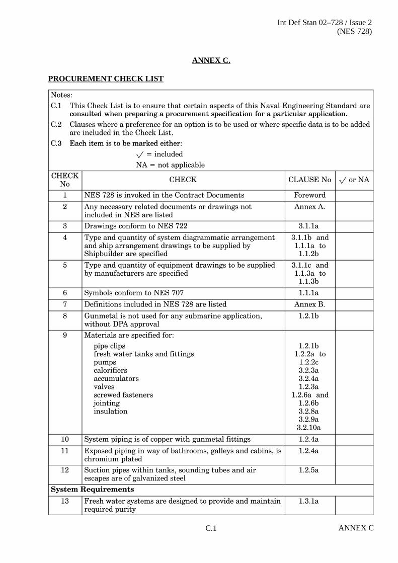
Int Def Stan 02–728 / Issue 2(NES 728)
ANNEX CC.1
ANNEX C.
PROCUREMENT CHECK LIST
Notes:
C.1 This Check List is to ensure that certain aspects of this Naval Engineering Standard areconsulted when preparing a procurement specification for a particular application.consulted when preparing a procurement specification for a particular application.
C.2 Clauses where a preference for an option is to be used or where specific data is to be addedare included in the Check List.
C 3 Each item is to be marked either:C.3 Each item is to be marked either:
� = included
NA = not applicable
CHECKNo
CHECK CLAUSE No � or NA
1 NES 728 is invoked in the Contract Documents Foreword
2 Any necessary related documents or drawings notincluded in NES are listed
Annex A.
3 Drawings conform to NES 722 3.1.1a
4 Type and quantity of system diagrammatic arrangementand ship arrangement drawings to be supplied byShipbuilder are specified
3.1.1b and1.1.1a to
1.1.2b
5 Type and quantity of equipment drawings to be suppliedby manufacturers are specified
3.1.1c and1.1.3a to
1.1.3b
6 Symbols conform to NES 707 1.1.1a
7 Definitions included in NES 728 are listed Annex B.
8 Gunmetal is not used for any submarine application,without DPA approval
1.2.1b
9 Materials are specified for:
pipe clipsfresh water tanks and fittingspumpscalorifiersaccumulatorsvalvesscrewed fastenersjointinginsulation
1.2.1b 1.2.2a to
1.2.2c 3.2.3a 3.2.4a 1.2.3a
1.2.6a and1.2.6b 3.2.8a 3.2.9a 3.2.10a
10 System piping is of copper with gunmetal fittings 1.2.4a
11 Exposed piping in way of bathrooms, galleys and cabins, ischromium plated
1.2.4a
12 Suction pipes within tanks, sounding tubes and airescapes are of galvanized steel
1.2.5a
System Requirements
13 Fresh water systems are designed to provide and maintainrequired purity
1.3.1a

Int Def Stan 02–728 / Issue 2(NES 728)
ANNEX C C.2
CHECKNo
CHECK CLAUSE No � or NA
14 System design provides maximum insurance againstaction damage
1.3.1a
15 Design meets daily consumption rate 1.3.1b
16 Design requirements of system conform to NES 710 andNES 797
1.3.1c
17 Pressure required at highest and most remote point ofsystems in HM Surface Ships is specified
1.3.1d
18 All compartments and services to be supplied with coldfresh water are specified
4.1.1.1a to4.1.1.2a
19 All compartments and services to be supplied with hotfresh water are specified
4.1.2.1a to4.1.2.2a
20 Scale of wash-basins and showers conform to NES 120 4.1.3a
21 Battery top�up requirements for Submarines are specified 1.3.3a to1.3.3
System Arrangement, HM Surface Ships
22 The number and size of fresh water storage tanksrequired is specified
1.4.1.1b and1.6.2.1a
23 The pumps and system are arranged to enable the pumpsto deliver water to the fresh water main and to transferwater within the ship
1.4.1.1e
24 Provision is made to prevent pumps overheating duringperiods of no discharge
1.4.1.1f
25 Each cold water pump can draw from any tank in thegroup associated with that pump
1.4.1.1g
26 The cold water pump suction pipework includes isolatingvalves, a non�return valve and a 1.5 mm aperture sizeduplex strainer
1.4.1.1h
27 The discharge pipework from the cold water pumpincludes an isolating valve and a non�return valve
1.4.1.1i
28 The number of pressure indicators required are specified 1.4.1.1j
29 The system is fitted with a local and remote readingpressure indicator for surveillance
1.4.1.1k
30 Hose connections are fitted on the suction and deliverysides of the cold fresh water pumps for use with a portablepump
1.4.1.1l
31 Filling and transfer lines are provided and arranged sothat distilling plants can supply feed and ships' tanksindependently
1.4.1.1m
32 Arrangements are made to supply essential services whenthose to remaining services have been isolated inemergency conditions
1.4.1.1o
33 Strainers are provided before special items of equipment 1.4.1.1p
34 Isolating valves are fitted in approved positions 1.4.1.1q and1.4.1.1r

Int Def Stan 02–728 / Issue 2(NES 728)
ANNEX CC.3
CHECKNo
CHECK CLAUSE No � or NA
35 Fresh water leads can be readily drained and emptied.Sections exposed to atmospheric temperatures can beisolated and drained
1.4.1.1s
36 `FROST' plugs are fitted in places where water maycollect after the system has been drained
1.4.1.1t
37 Precautions against water�hammer are provided. Airchambers are fitted at the top of each riser and at the endof horizontal lines
1.4.1.1u
38 Air vents are fitted at the highest point of piping systems,and vent pipes led to convenient drainage systems
1.4.1.1v and1.11.15d
39 Emergency leads from the fresh water main are led to thevicinity of cabinets normally cooled by tepid water
1.4.1.1x
40 There is no cross�connection between the fresh and saltwater systems
1.4.1.1y
41 The system pressure exceeds 0.35 bar at the highest pointand is adequate at all special users during normaloperation:
a. When a boost pump is in use or,
b. Without a boost pump
1.4.1.1z
42 The boost system is provided with:
a. a control orifice return to the fresh water main
b. isolating valves, non�return valve and suction strainer
c. suction and discharge pressure indicators
1.4.1.1aa
43 The hot water systems are arranged as ring mains withthermo�syphon or pumped circulation and short branches.The systems are pressurized from the cold fresh watersupply
1.4.2.1i
44 Calorifiers are supplied from the cold fresh water mainand fitted with isolating valve and non�return valve
1.4.2.1e
45 The calorifier storage capacity is adequate to ensure thatat times of peak demand the temperature of the outlets ofthe hot water system does not drop below 60°C
1.4.2.1k
46 Local water heaters are provided where required inpreference to a boost system
1.4.2.1m
System Arrangement, Submarines
47 Fresh water storage tanks are pressurized either from theAuxiliary Vent and Blow System or a continuous runningpump system is used
1.4.1.2a
48 The number and size of tanks required are specified 1.4.1.2b and1.6.2.2a
49 The system operating pressure required is specified 1.4.1.2e
50 An inboard hose connection is provided for filling from anoutboard source with a conveniently positioned fillingcontrol station
1.4.1.2g

Int Def Stan 02–728 / Issue 2(NES 728)
ANNEX C C.4
CHECKNo
CHECK CLAUSE No � or NA
51 Feed water may be used to augment the fresh water 1.4.1.2h
52 One storage tank can supply water to the main while theother is being filled from the fresh water filling line
1.4.1.2i
53 Weapon spray tank is provided and can be maintained fulland to be capable of being pressurized to the systemoperating pressure as specified in the appropriateContract Document
1.4.1.2j
54 Facilities are provided for connecting both a shore FW/SWsupply and a SW back�up from the HP bilge system orsuitable alternative system to the spray system
1.4.1.2l
55 Piping within the containment boundary is suitable forresisting the containment pressure or be provided witheasily accessible isolation valves at and outside, but asclose as is practical to the containment boundary
1.4.1.2m
56 Isolating valves, tested to the appropriate pressure, arefitted on both sides of escape bulkheads and on theoutside of containment boundary penetrations
1.4.1.2n
57 The hot water system consists of a calorifier, pressurizedfrom the cold water system and a natural circulation ringmain
1.4.2.2a to1.4.2.2f
58 The calorifier heating capacity is adequate to supplysufficient hot water at a temperature of 71°C
4.1.2.2a
Desalination Requirements
59 The capacity of the desalination plant to be in accordancewith NES 328
1.5.1a
60 Additional allowances required for gas turbine washing,for aircraft washing and for feed water purposes
1.5.2a
61 Additional allowance required for feed make�up purposesin Submarines
1.5.2a
Fresh Water Storage and Filling
62 The quantity of fresh water to be stored on board 1.6.1a
63 The filling system is to be capable of accepting RAS andShore supply
1.6.3.1b
64 Filling positions required are specified:
a. HM Surface Ships
b. Submarines
1.6.3.1c to g
1.6.3.2b
65 Filling funnels are fitted above crown of each storage tank 1.6.3.1h
Fresh Water Storage Tanks
66 Tanks to conform to NES 110 3.6.1.1a
67 Non�ferrous fittings not used in tanks 1.2.2c
68 Adequate access to tank is provided 1.6.2.1g and1.6.2.1h

Int Def Stan 02–728 / Issue 2(NES 728)
ANNEX CC.5
CHECKNo
CHECK CLAUSE No � or NA
69 No piping or gearing passes through tank except whererequired for operation of the fresh water system
1.6.2.1i
70 An aerating rose is fitted on the filling line within eachtank
1.6.3.1i
71 Tanks are fitted with air escape pipes arranged toterminate above the RED RISK zone
1.6.6a and1.6.6e
72 Each tank is fitted with a continuous distant reading typecontents gauge
1.6.3.1j
73 Fittings are provided to facilitate sterilization of the freshwater in each tank
1.6.4a and1.6.4b
74 Sounding tubes are provided in each tank 1.6.5a to1.6.5d
75 The requirements for radiographic examination of weldsof tank plating are specified
3.9.6b and3.9.6c
76 Internal preservation of tanks conforms to NES 763 3.10.2a
78 Calibration requirements for tanks are specified 1.12.3a to1.12.3c
79 Pressure testing requirements for tanks are specified 1.12.4.2a
Pumps
80 Pumps conform to NES 327 1.7.1b
81 Cold water pumps are of self�priming type 1.7.1c
82 Adequate protection is provided to safeguard pumps 1.7.3b and1.7.6a
83 The pump leak�off orifice is sized correctly 1.7.6c
84 The hot water circulating pump motor is not overloadedwhen the pump runs-out on its characteristic
1.7.6d
Calorifiers
85 Hot water storage capacity requirements are correctlydetermined
1.4.2.1k to1.4.2.2c
86 Calorifiers conform to NES 329 1.8.3a
87 Individual electric water heaters required for medical andother compartments are specified
1.8.3b
88 Requirements for steam/water mixtures are specified 1.8.3d
89 Hot water tank requirements for Submarines are specified 1.8.4a
90 Local calorifier requirements for Submarines 1.8.4
Drinking Water
91 Number, capacity and location of drinking water tanks arespecified
1.9.1a to1.9.1d
92 Drinking water coolers 1.4.1.1o (3)
93 Number and location of drinking water coolers requiredare specified
1.9.2b

Int Def Stan 02–728 / Issue 2(NES 728)
ANNEX C C.6
CHECKNo
CHECK CLAUSE No � or NA
94 Cooled fresh water requirements are specified 1.9.3a and1.9.3b
95 Equipment for the supply of cooled fresh water 1.9.2a
Auxiliary Components
96 Size of accumulator required is specified 1.11.14c to1.11.14f
97 Accumulators are selected from standard range 1.10.1c
98 Submarine tank air pressure charging equipment reducedair pressure requirements are specified
1.10.2b to1.10.2c
99 Piping and fittings, connections/flanges, screwed fastenersand jointing are selected from the standard range given inBR 3013(2), Part 2
3.8.2.1a ,3.8.2.3a
100 Valves are selected from the standard range given in NES360
3.8.3a
101 Push cocks are of the non�concussion type 3.8.3b
102 Line valves for submarine fresh water systems are of theball type
3.8.3c
103 Strainers to be provided 3.8.4a
104 Requirements for air release units are specified 1.10.4a
System Details
105 The arrangement and sizing of pipework in bathrooms,conforms to NES 120
1.11.4a
106 The correct design flow for each size of outlet is used incalculations
1.11.5a
107 The correct diversity factor is applied in calculations 1.11.5c
108 All outlets requiring large quantities of water areadequately supplied
1.11.5d
109 The number and size of pumps required is specified 1.11.2l
110 Orifice plates are fitted at outlets where the pressureexceeds 2 bar
1.11.8b
111 The total calorifier heating capacity is capable of heating0.012 m3/h per man of complement
1.11.10b
112 The accumulators have adequate capacity 1.11.14f
113 Averaging and diversity factors produce a result that iscomparable to the installation on existing ships of thesame size
1.11.3a
114 The branch pressure pipe sizes are adjusted, if requiredafter calculating the pressure loss in each branch, toequalize the pressures at outlets to the greatest possibleextent
Annex C
115 Air removal requirements are specified 1.11.15a
116 Requirements for standard of workmanship and finish arespecified
3.9.1a

Int Def Stan 02–728 / Issue 2(NES 728)
ANNEX CC.7
CHECKNo
CHECK CLAUSE No � or NA
117 Requirements for manufacturing processes conform tospecifications
3.9.2a to3.9.5b
118 Requirements for cleaning and preservation conform tospecifications
3.10.1a to3.10.3a
119 Prohibition on use of red and white lead in systems 3.10.1b
Installation
120 Requirements for flexibility are specified 1.12.1a
121 Requirements for piping installation are specified 1.12.2a to1.12.2w
122 Inspection and flushing requirements are specified 3.11.3a
123 Requirements for pressure tests are specified 1.12.4a to1.12.4.3a
124 Requirements for trials to demonstrate the correctfunctioning of the systems are specified
1.12.5a
125 Thermal insulation conforms to NES 703 1.12.6a
126 Requirements for colours and marking of fresh waterpiping systems are specified
1.12.7a to1.12.7d
This Check List may be subjected to revision after other relevant NES have been finalized

Int Def Stan 02–728 / Issue 2(NES 728)
ANNEX C C.8

Int Def Stan 02–728 / Issue 2(NES 728)
ANNEX DD.1
ANNEX D.
SAMPLE CALCULATIONS
D.1. INTRODUCTION
a. The sample calculation is based on a typical fresh water system for aFrigate/Destroyer. The sample calculation is in SI units using metric pipe sizes.
b. Whilst it is necessary to carry out an analysis of the entire cold and hot watersystems in order to determine the pressures at the various points and themaximum required pressure from the cold water pumps, for simplicity thesesample calculations have been abbreviated to show only the major steps.Estimated values are shown for the omitted steps. Such estimated values areindicated with an asterisk.
c. Similarly for the calorifiers, hot water circulating pumps and accumulators thecalculations for one set of equipment only are shown.
D.2. GENERAL CALCULATIONS
a. Data Sheet D1/1 is used to calculate and record the capabilities of the maincomponents associated with the fresh water systems.
b. Fresh Water Storage
Fresh water storage is based on five days consumption and is currently definedas being 1.0 m3 per person minimum in Surface Ships, see Clause 1.6.1a.Provision for FW storage capacities required to support the envisagedoperations of the vessel is needed, not just against the minimum requirementswithin this standard.
c. Filling Rate
The filling rate is to be 100 m3/h in ships of Frigate/Destroyer size and 50 m3/hin ships below Frigate/Destroyer size, see Clause 1.6.3.1b .
d. Desalination Requirements
The desalination plant capacity is to include an allowance of 200 litres per dayper person of complement in Surface Ships, see Clause 1.3.1b
Additional desalination plant capacity is to be provided when appropriate forgas turbine washing, aircraft washdown, ship husbandry and for feed make�up,see NES 328.
e. Total Number of Outlets
Information on the number and size of outlets is to be taken off thediagrammatic arrangement drawings. Outlets which are not in daily use, e.g.emergency supplies to sonar cooling systems and decontamination stations areto be ignored. Showers are counted in both the hot and cold water systems.
f. Total Diversity Factor
The total diversity factor is related to the total number of outlets on the vessel.It is determined from Figure 1.12., Clause 1.11.
g. Design Requirements

Int Def Stan 02–728 / Issue 2(NES 728)
ANNEX D D.2
The size and number of outlets will be as determined at D.2.e
The diversity factor is the total system diversity factor as determinedat D.2.f
The flow per outlet is to be taken as shown in Table 1.7 given inClause 1.11.5e . The outlet of 0.27 m3/h for showers is taken 50% from the hotwater system and 50% from the cold water system.
h. Design Cold Water Pump Capacity
The design cold water pump capacity is to be the total design flow as calculatedat Step D.2.g
i. Design Water Requirements from Boost Pump
The conditions which govern the necessity for a boost pump are given in Clause1.11.7a .
The diversity factor to be used in calculating the boost pump capacity is to bethat appropriate to the number of outlets served by the boost pump and isdetermined from Figure 1.12.

Int Def Stan 02–728 / Issue 2(NES 728)
ANNEX DD.3
CALCULATION DATA SHEET D1/1 – GENERAL CALCULATIONS
INSTALLATION Typical COMPLEMENT 460
1. Fresh Water Storage
Storage required by rules = 1.0 m3/person
= 460 x 1.0 = 460 m3
Storage actually fitted = say 460 m3
Arrangement 2 groups of tanks. (1 forward and 1 aft)
2. Filling Rate
Filling arrangements to be designed for 50 m3/h
3. Desalination Requirement
Capacity required by rules (for domestic use)
= 0.2 m3/person/day
= 92 m3/day
= 3.83 m3/h
Capacity actually fitted (includes for boilers)
= 2 � 4 m3/h
4. Total Number of Outlets
Size of outlet WB 6 mm 13 mm Shower 19 mm Total
Cold water system 104 16 74 30 3 227
Hot water system 104 - 31 30 3 168
Total number of outlets 208 16 105 60 6 395
5. Total Diversity Factor
Total number of outlets 395 Diversity factor 0.085

Int Def Stan 02–728 / Issue 2(NES 728)
ANNEX D D.4
6. Design Requirements (see Clause D.2.e)
Size of OutletNumber of
OutletsDiversity
FactorFlow per
Outlet (m3/h)Design Flow
(m3/h)
6 mm 16 0.085 0.07 0.10
WB 208 0.085 0.27 4.77
13 mm 105 0.085 0.57 5.09
Showers 60* 0.085 0.14 0.71
19 mm 6 0.085 1.63 0.83
395 11.50
* The 60 shower outlets are 30 hot outlets and 30 cold outlets
7. Design Cold Water Pump Capacity Required
= 11.50 m3/h
8. Design Water Requirements From Boost Pump (if fitted)
Size of OutletNumber of
OutletsDiversity
FactorFlow per
Outlet (m3/h)Design Flow
(m3/h)
BOOST PUMP NOT REQUIRED
9. Design Boost Pump Capacity Required
= m3/h
Table D.1 – Calculation Data Sheet

Int Def Stan 02–728 / Issue 2(NES 728)
ANNEX DD.5
D.3. Water Flow and Approximate Pipe Bore Calculation (Cold Water System)
Data Sheet D2/1 is used to record the water flow in each pipe section and then to makea preliminary selection of pipe size. It is a necessary prerequisite to this stage that thesystem line diagram described in Clause 1.11.2a is available.
a. Data Sheet D2/1 records this information for the cold water main when it isbeing supplied from the aft pump only. Each section is considered as passing thequantity of water required by all the downstream outlet. The flow from the coldwater system to each shower is taken as 0.014 m3/h (half the total shower flow).A diversity factor determined from Figure 1.12 is applied to the flow for thenumber of outlets being supplied.
CALCULATION DATA SHEET D2/1 – WATER FLOW AND APPROXIMATE PIPE BORECALCULATION
System COLD Piping MAIN Pump in use AFT
1.
S
2.
b f
3. 4.
l S
5.
SSectionReference
Number ofOutlets
DiversityFactor
Water Flow in Pipe Section
(m3/h)
Pipe Size
(mm)Reference OutletsDownstream
Factor (m3/h) (mm)
Pump to A 395 0.085 Design FlowFrom Data Sheet C1/2(Step 6) 11.5
54
A to B 390 0.086 16 � 0.086 � 0.07 = 0.10
208 � 0.086 � 0.27 = 4.83
100 � 0.086 � 0.57 = 4.90
60 � 0.086 � 0.14 = 0.72
6 � 0.086 � 1.63 = 0.84
11.39
54
B to C 389 0.086 As for A to B minus
1 � 0.086 � 0.27 = 0.023
11.39 - 0.02 = 11.37
54
C to D 388 0.087 As for B to C minus
1 � 0.087 � 0.57 = 0.05
11.37 - 0.05 = 11.32
54
D to E 338 0.087 16 � 0.087 � 0.07 = 0.10
179 � 0.087 � 0.27 = 4.20
88 � 0.087 � 0.57 = 4.36
50 � 0.087 � 0.14 = 0.61
5 � 0.087 � 1.63 = 0.71
9.98
54
T to U
The above details are to be completed for all sections of main piping

Int Def Stan 02–728 / Issue 2(NES 728)
ANNEX D D.6
b. A preliminary pipe bore is selected on the basis of passing the required quantityof water at a reasonable speed and without excessive pressure loss. Table 1.4will be of assistance as it shows the maximum flow in each size of pipe. In orderto provide some slack in the system and to permit the passage of enhanced flowwhen required it is recommended that water speeds in mains should generallybe restricted to 50% to 70% of the maximum permitted.
c. The filling and transfer lines, which are used only intermittently and in whichpressure drop is of secondary importance, may be selected to operate at thehighest permissible water speed.
d. Data Sheet D2/2 records the information on the cold water main when it is beingsupplied from the forward pump only. The information recorded is similar tothat on Data Sheet D2/1 for the use of the aft pump.
e. For some sections the size of pipe initially determined in the calculations onData Sheet D2/1 and D2/2 will not be the same. The larger of the two sizes is tobe selected.
CALCULATION DATA SHEET D2/2 – WATER FLOW AND APPROXIMATE PIPE BORECALCULATION
System COLD Piping MAIN Pump in use FORWARD
1.
S i
2.
N b f
3.
Di i
4.
W Fl i Pi S i
5.
Pi SiSectionReference
Number ofOutlets
DiversityFactor
Water Flow in Pipe Section
(m3/h)
Pipe Size
(mm)Reference OutletsDownstream
Factor (m3/h) (mm)
Pump to U 395 0.085 Design FlowFrom Data Sheet C1/2(Step 6) 11.5
54
U to T 307 0.087 16 � 0.087 � 0.07 = 0.10
208 � 0.087 � 0.27 = 3.45
101 � 0.087 � 0.57 = 5.01
37 � 0.087 � 0.14 = 0.45
6 � 0.087 � 1.63 = 0.85
9.86
54
T to S 301 0.088 16 � 0.088 � 0.07 = 0.10
144 � 0.088 � 0.27 = 3.42
98 � 0.088 � 0.57 = 4.92
37 � 0.088 � 0.14 = 0.46
6 � 0.088 � 1.63 = 0.86
9.76
54
S to R etc.
E to D 57 0.19 29 � 0.19 � 0.27 = 1.49
17 � 0.19 � 0.57 = 1.84
10 � 0.19 � 0.14 = 0.27
1 � 0.19 � 1.63 = 0.31
3.91
54
B to A

Int Def Stan 02–728 / Issue 2(NES 728)
ANNEX DD.7
f. Data Sheet D2.3 records information on the branches corresponding to that forthe main recorded in calculations on Data Sheets D2/1 and D2/2.
g. At this stage there should be a check to confirm that the pipe sizes selected forthe main and branches will be capable of giving an adequate supply to anyparticularly large users. It should also be remembered that there are specialrequirements for the size of pipes supplying groups of showers andwash-basins.
CALCULATION DATA SHEET D2/3 – WATER FLOW AND APPROXIMATE PIPE BORECALCULATION
AFT or
System COLD Piping BRANCHES Pump in use FORWARD
1.
S
2.
b f
3. 4.
l S
5.
SSectionReference
Number ofOutlets
DiversityFactor
Water Flow in Pipe Section
(m3/h)
Pipe Size
(mm)Reference OutletsDownstream
Factor (m3/h) (mm)
A to 1 5 0.84 5 � 0.84 � 0.57 = 2.39 28
B to 2 1 1.0 1 � 1.0 � 0.27 = 0.27 12
C to 2.1 1 1.0 1 � 1.0 � 0.57 = 0.57 15
D to 3 50 0.20 28 � 0.20 � 0.27 = 1.51
11 � 0.20 � 0.57 = 1.25
10 � 0.2 � 0.14 = 0.24
1 � 0.2 � 1.63 = 0.33
3.33
35
3 to 4 18 0.44 12 � 0.44 � 0.27 = 1.43
5 � 0.44 � 0.14 = 0.31
1 � 0.44 � 0.57 = 0.25
1.99
28
4 to 5 17 0.46 11 � 0.46 � 0.27 = 1.37
5 � 0.46 � 0.27 = 0.62
1 � 0.46 � 0.57 = 0.26
2.25
28
5 to 6 12 0.57 11 � 0.57 � 0.27 = 1.69
1 � 0.57 � 0.57 = 0.32
2.01
28
6 to 7
7 to 8
D to 7
F to 8
U to 55
The above details are to be completed for all sections of all branches.

Int Def Stan 02–728 / Issue 2(NES 728)
ANNEX D D.8
D.4. Physical Data (Cold Water System)
a. Data Sheet D3/1 is used to record the physical characteristics of the pipingsystems. Before it can be prepared it is necessary to have available the pipingdiagram on ship deck plans described in Clause 1.11.2f .
b. Data Sheet D3/1 records the physical data for the cold water main starting atthe aft tank and working forward.
CALCULATION DATA SHEET D3/1 – PHYSICAL DATA
System COLD Piping MAIN Pump in use AFT
1.
Section
2.
Length
3.
Elbows
4.
Tee pieces
5.
Tee pieces
6.
Other
7.
Stop CocksSectionReference
Length(m)
Elbows Tee�pieces(Flow Past)
Tee�pieces(Flow Round)
OtherFittings
Stop Cocksand Valves
Tank to Pump 5.0 3 1 2 1Strainer
1 NRV
Pump to A 2.4 2 3 - 1Strainer
2 Ball
A to B 1.2 - - 1 - -
B to C 2.5 - 1 - - -
C to D 1.0 - 1 - - -
D to E 7.3 - 1 - - -
E to F 6.4 - 1 - - -
F to G 34.5 1 2 1 - -
G to H 0.6 - 1 - - -
H to J 3.1 - 1 - - -
J to K 3.9 - 1 - - -
K to L 0.6 - 1 - - -
L to M 2.5 - 1 - - -
M to N 7.9 - 1 - - -
N to P 2.5 - 1 - - -
P to Q 5.4 - 1 - - -
R to S 10.9 - 1 - - -
S to T 15.1 - 1 - - -
T to U 4.2 1 - 1 - -

Int Def Stan 02–728 / Issue 2(NES 728)
ANNEX DD.9
Data Sheet D3/2 records the physical data for the cold water main, starting at the forwardtank and working aft. For intermediate sections the data recorded will be identical withthat on Data Sheet D3/1 but listed in the reverse order.
CALCULATION DATA SHEET D3/2 – PHYSICAL DATA
System COLD Piping MAIN Pump in use FORWARD
1. 2. 3. 4. 5. 6. 7.
SectionReference
Length(m)
Elbows Tee�pieces(Flow Past)
Tee�pieces(Flow Round)
OtherFittings
Stop Cocksand Valves
Tank to Pump 5.0 3 1 1 1Strainer
1 NRV
Pump to U 9.6 3 4 1 1Strainer
2 Ball
U to T 4.2 1 - 1 - -
T to S 15.1 - 1 - - -
S to R 10.9 - 1 - - -
R to Q 3.6 - 1 - - -
Q to P 5.4 - 1 - - -
P to N 2.5 - 1 - - -
N to M 7.9 - 1 - - -
M to L 2.5 - 1 - - -
L to K 0.6 - 1 - - -
K to J 3.9 - 1 - - -
J to H 3.1 - 1 - - -
H to G 0.6 - 1 - - -
G to F 34.5 1 2 1 - -
F to E 6.4 - 1 - - -
E to D 7.3 - 1 - - -
D to C 1.0 - 1 - - -
C to B 2.5 - 1 - - -
B to A 1.2 - - 1 - -

Int Def Stan 02–728 / Issue 2(NES 728)
ANNEX D D.10
Data Sheet D3/3 records the physical data for the cold water system branches.
CALCULATION DATA SHEET D3/3 – PHYSICAL DATA
FORWARD
System COLD Piping BRANCHES Pump in use or AFT
1. 2. 3. 4. 5. 6. 7.
SectionReference
Length(m)
Elbows Tee�pieces(Flow Past)
Tee�pieces(Flow Round)
OtherFittings
Stop Cocksand Valves
A to 1 19.4 4 4 1 - 1
B to 2 2.1 1 - 1 - 1
C to 2.1 5.0 2 - 1 - 1
D to 3 2.7 1 - 1 - 1
3 to 4 10.9 3 4 - - -
4 to 5 1.5 - - 1 - -
5 to 6 1.8 2 1 - - -
D to 7 11.5 2 - 1 - 1
E to 8 4.8 1 - 1 - 1
F to 9
9 to 10
40 to 42 19.7 2 + 6,45°
1 1 - 1
U to 55
The above details are to be completed for all branches of the system.
D.5. Pipe Friction Calculations (Cold Water System Main)
a. Data Sheet D4/1 is used for calculating the piping system pressure loss. It hasbeen designed for use with the equivalent length method of determining thepressure loss of valves and fittings. The use of this system is justified because ofthe continuous variation in flow that occurs.
b. Calculations on Data Sheet D4/1 determines the pressure loss in the cold mainwhen the aft pump is in use.
c. The information on this Data Sheet is derived as follows:
Column 1 - Pipe section reference;
Column 2 - The design water flow from Data Sheet D2/1;
Column 3 - The system components from Data Sheet D3/1;
Column 4 - Equivalent length coefficients for the components. These arelisted in Table 1.5, Section 1.11;
Column 5 - Pipe bore, the initial selection has been made on Data SheetD2/1;
Column 6 - Is used to calculate the equivalent length of the systemcomponents;
Column 7 - Actual length of pipe taken from Data Sheet D3/1;

Int Def Stan 02–728 / Issue 2(NES 728)
ANNEX DD.11
Column 8 - Column 6 added to Column 7
Columns 9and 10 -
Are read from the Pressure Loss Chart, Figure 1.10,Section 1.11 The head loss in column 10 recorded (in bar) isfor 1 m length of pipe;
Column 11 - Column 10 multiplied by the total equivalent length given inColumn 8;
Column 12 - The static pressure drop (in bar) due to the height of the endof the pipe section above datum. The datum is to be taken asthe bottom of the fresh water tank relative to the pump beingconsidered;
Column 13 - The total head loss (in bar) from the bottom of the fresh waterstorage tank to the end of the pipe section being considered.This is obtained from the sum of the friction head losses in thepipe sections along the flow route and the height of the pipesection above the datum.

Int Def S
tan 02–728 / Issue 2(N
ES
728)
AN
NE
X D
D.12
CALCULATION DATA SHEET D4/1 – PIPE FRICTION CALCULATIONS
System COLD Piping MAIN Pump in use AFT
1.Section
2.Flow
3
3.System Components
4.Equivalent
5.Pipe
6.Component
7.Actual
8.Total
9.Water
10.Head
11.Section
12.Height
13.TotalSection
ReferenceFlow
(m3/h)System Components Equivalent
LengthCoefficient
K
PipeBore
D( )
ComponentEquivalent
Length
K D
ActualLength
(m)
TotalEquivalent
Length( )
Waterspeed(m/s)
Headloss
(bar/m)
Sectionloss
(bar)
HeightaboveDatum(b )
Totalloss tosection(b )K (mm) K � D
1000� (m)
(m) (bar) (bar)
Tank toPump
11.5 ElbowsTees (flow past)Tees (flow round)StrainersNR Valves
31211
12 � 3 = 36-70 � 2 = 14040 � 1 = 4060 � 1 = 60Total = 276
50 13.8 5.0 18.8 1.62 0.0056 0.0056� 18.8= 0.11
0.18 0.11+ 0.18= 0.29
Pump toA
11.5 ElbowsTees (flow past)StrainerBall Valves
2312
12 � 2 = 24-40 � 1 = 4015 � 2 = 30Total = 94
50 4.7 2.4 7.1 1.62 0.0056 0.0056� 7.1= 0.04
0.43 0.11+ 0.04+ 0.43= 0.58
A to B 11.39 Tees (flow round) 1 70 � 1 = 70Total = 70
50 3.5 1.2 4.7 1.61 0.0054 0.0054� 4.7= 0.025
0.43 0.58+ 0.025= 0.605
B to C 11.37 Tees (flow past) 1 - 50 - 2.5 2.5 1.60 0.0053 0.0053� 2.5= 0.013
0.605+ 0.013= 0.618
C to D
D to E
T to U
The above details are to be completed for all sections of piping.
a. Calculations on Data Sheet D4/1 determine the pressure loss in the cold main when the forward pump is in use. Informationand data for Columns 2 and 5 are taken from Data Sheet D2/2 and for Columns 3 and 7 from Data Sheet D3/2.

Int Def S
tan 02–728 / Issue 2(N
ES
728)
AN
NE
X D
D.13
CALCULATION DATA SHEET D4/2 – PIPE FRICTION CALCULATIONS
System COLD Piping MAIN Pump in use FORWARD
1.Section
2.Flow
3
3.System Components
4.Equivalent
5.Pipe
6.ComponentE i l t
7.Actual
8.Total
9.Water
10.Head
11.Section
12.Height
13.TotalSection
ReferenceFlow
(m3/h)System Components Equivalent
LengthCoefficient
K
PipeBore
D( )
pEquivalent
Length
K D
ActualLength
(m)
TotalEquivalent
Length( )
Waterspeed(m/s)
Headloss
(bar/m)
Sectionloss
(bar)
HeightaboveDatum(b )
Totalloss tosection(b )K (mm) K � D
1000� (m)
(m) (bar) (bar)
Tank toPump
11.5 ElbowsTees (flow past)Tees (flow round)StrainersNR Valves
31111
10 � 3 = 30-70 � 1 = 7040 � 1 = 4060 � 1 = 60Total = 200
50 10.3 5.0 15.3 1.62 0.0056 0.0056� 15.3= 0.086
0.18 0.18+ 0.086= 0.266
Pump toU
11.5 ElbowsTees (flow past)Tees (flow round)StrainersBall Valves
34112
12 � 3 = 36-70 � 1 = 7040 � 1 = 4015 � 2 = 30Total = 176
50 8.8 9.6 18.4 1.62 0.0056 0.056� 18.4= 0.103
0.43 0.086+ 0.103+ 0.43= 0.619
U to T 9.86 ElbowsTees (flow round)
11
12 � 1 = 1270 � 1 = 70Total = 82
50 4.1 4.2 8.3 1.38 0.0042 0.0056� 8.3= 0.035
0.67 0.189+ 0.035+ 0.67= 0.894
T to S 9.76 Tees (flow past) 1 - 50 - 15.1 15.1 1.36 0.0042 0.0042� 15.1= 0.063
0.67 0.894+ 0.063= 0.957
S to R
R to Q
E to D 3.91 Tees (flow past) 1 - 50 - 7.3 7.3 0.53 0.00078
0.00078� 7.3= 0.006
0.43 1.026*+ 0.006= 1.032
B to A
The above details are to be completed for all sections of piping.* Estimated value

IntDef Stan 02–728 / Issue 2(NES 728)
ANNEX D D.14
D.6. Pipe Friction Calculations (Cold Water System Branches)
a. Calculations on Data Sheet D4/3 continue the pressure drop calculation withdetermination of the loss in the branches with either pump in use. Informationand data are taken from Data Sheets D2/3 and D3/3.
b. The pressure drop to the start of each branch is different for the aft pump thanfor the forward pump. Additionally in this example, the aft and forward storagetanks are at different levels. It is therefore necessary to make separatecalculations of total pressure drop for either pump in use.
c. At the conclusion of these calculations, comparison of the pressure drop in eachbranch is to be made to determine if it would be possible to make the pressuredrops more equal. This will involve the use of increased water speed in brancheson lower decks. Care must be taken not to exceed the water speeds given inTable 1.4 (see Clause 1.11.8a ) and to provide a pipe of the correct size forsupplying wash-basins and showers (see NES 120).
d. A note is to be made of all wash-basins and showers on the cold water systemwhich have a pressure greater than 2 bar. These outlets are to be fitted with anorifice as described in Clause 1.11.8b .

Int Def S
tan 02–728 / Issue 2(N
ES
728)
AN
NE
X D
D.15
CALCULATION DATA SHEET D4/3 – PIPE FRICTION CALCULATIONS
System COLD Piping BRANCHES Pump in use AFT or FORWARD
1.Section
R f
2.Flow
( 3/h)
3.System Components
4.Equivalent
L th
5.PipeB
6.ComponentE i l t
7.ActualL th
8.Total
E i l t
9.Water
d
10.Headl
11.Section
l
12.Height
b
13.Totall tReference (m3/h)
y p qLength
CoefficientK
pBore
D(mm)
pEquivalent
LengthK � D
Length(m)
EquivalentLength
(m)
speed(m/s)
loss(bar/m)
loss(bar)
gaboveDatum(bar)
loss tosection(bar)K (mm) K � D
1000� (m)
(m) (bar) (bar)
A to 1 2.39 ElbowsTees (flow past)Tees (flow round)Ball Valve
4411
12 � 4 = 48-250 � 1 = 25015 � 1 = 15Total = 313
25.6 8.0 19.4 27.4 1.32 0.008 0.008� 27.4= 0.22
A 0.43
F 0.67
0.58+ 0.22= 0.80
1.23*+ 0.22= 1.45
B to 2 0.27 ElbowTees (flow round)Ball Valve
111
12 � 1 = 12120 � 1 = 12015 � 1 = 15Total = 147
10.4 1.5 2.1 3.6 0.88 0.013 0.013� 3.6= 0.047
A 0.43
F 0.67
0.605+ 0.047= 0.652
1.112*+ 0.047= 1.159
C to 2.1
D to 3
3 to 4
40 to 42 0.64 ElbowsBend (45°)Tees (flow past)Tees (flow round)Ball Valve
26111
12 � 2 = 248 � 6 = 48-70 � 1 = 7015 � 1 = 15Total = 157
19.6 3.1 19.7 22.8 0.59 0.0028 0.0028� 22.8= 0.064
A 1.65
F 1.89
2.242*+ 0.064= 2.306
2.441*+ 0.064= 2.505
R to 43
U to 55
The above details are to be completed for all sections of piping.
NOTE:* Estimated valueA Flow from aft pumpF Flow from forward pump

Int Def Stan 02–728 / Issue 2(NES 728)
ANNEX D D.16
D.7. Selection of Cold Water Pump and Cold Water Boost Pump
a. Data Sheet D5 is used for the selection of the cold water pump and cold waterboost pump. These pumps are not used in Submarines.
b. Information on the selection of cold water and boost pumps is given inSection 1.7.
c. Data Sheet D5 is filled in as follows:
(1) The cold water pump capacity required is to be taken fromData Sheet D1/2;
(2) The differential pressure required from the pump is to be the pressure lossin the system as determined in Data Sheet D/4, with 10% safety marginand the addition of the pressure required at the highest point, this is tobe taken as 0.35 bar unless there is a specific requirement for a greaterpressure, e.g. Bridge Window Washer System 1.4 bar and head lift abovemain to windows. See also Clause 1.3.1d;
(3) On ships of Frigate/Destroyer size and above four pumps are required, onships smaller than these two pumps are required.
d. The necessity for a cold water boost pump will have been determined inData Sheet D1/2. The pressure development required is taken fromData Sheet D4/-, Column 13.

Int Def Stan 02–728 / Issue 2(NES 728)
ANNEX DD.17
CALCULATION DATA SHEETS D5 – SELECTION OF COLD WATER PUMP AND COLDWATER BOOST PUMP
1. Cold Water Pump
a. Cold Water Pump Capacity Required (Data Sheet D1/1) = 11.5 m3/h
b. Pressure:
Maximum Pressure Loss in System(Data Sheet D4/-, Column 13)
= 2.51 bar + 10% margin = 2.76 bar
Minimum Pressure Required at Highest/Most Remote Point (if height is involved the = 0.35 barhead lift must also be added)
Differential Pressure Required from Pump
= 2.69 + 0.35 = 3.04 bar
c. Number of Pumps Required by Rules(see Clause 1.11.2l ) = 2
d. Pump Duty (100% Standby on DiversityFactor) see Figure 1.5 and Figure 1.6 in Clause 1.7
Output
= 12 m3/h Differential Pressure = 3.04 bar
e. Pump Arrangement
1 Forward 1 Aft - Amidships
f. Pumps Actually Fitted
2. Cold Water Boost Pump
a. Not Required;
b. Output (Data Sheet D1/1) = m3/h
c. Pressure:
Maximum Pressure Loss in System bar(Data Sheet D4/-, Column 13)
Minimum Pressure Required atHighest/Most Remote Point (see above) = 0. 35 bar
Differential Pressure Requiredfrom Pump =+0.35= bar
d. Location

Int Def Stan 02–728 / Issue 2(NES 728)
ANNEX D D.18
D.8. Water Flow Rates from Calorifiers
a. Data Sheet D6 is used to calculate the total hot water heat load and thedistribution of this load between the calorifiers.
b. The hot water required on Surface Ships is 0.012 m3/h per person and thisrequires a heater of 0.77 kW per person. (see Clause 1.11.10b).
c. The number and type of outlet on each of the hot water systems are determinedand the diversified flow for each system calculated using Figure 1.12,Clause 1.11.
d. The total required heating capacity is to be allocated between the hot watersystems in proportion to their diversified flow. The calculated heating power isrounded up to the nearest convenient value.
e. The storage capacity is required to be determined by using the informationgiven in Clauses 1.11.12a or 1.11.12b and Figure 1.14 to Figure 1.18 inclusive.
f. It will be noted that in the example the forward calorifier, which serves mainlyshowers and wash-basins, has a heating capacity per outlet that is lower thanthe other two systems. Because of this low heating rate and the fact thatshowers may be used continuously for substantial periods the storage capacityof the forward system has been made proportionally greater.

Int Def Stan 02–728 / Issue 2(NES 728)
ANNEX DD.19
CALCULATION DATA SHEET D6 – HOT WATER FLOW FROM CALORIFIERSHEAT REQUIREMENT
Complement 460
Total hot water required at 0.012 m3/h per person 5.52 m3/h
Total Calorifier heating capacity at 0.77 kW/person 354 kW
Design Requirements
System Aft Diversity Factor 0.29
Type of OutletNumber of
OutletsDiversity
FactorFlow per
Outlet (m3/h)Design Flow
(m3/h)
WB 16 0.29 0.27 1.25
13 mm 10 0.29 0.57 1.65
Showers 5 0.29 0.14 0.20
19 mm 1 0.29 1.63 0.47
32 3.57
System Midships Diversity Factor 0.16
Type of OutletNumber of
OutletsDiversity
FactorFlow per
Outlet (m3/h)Design Flow
(m3/h)
6 mm & WB 45 0.16 0.27 1.94
13 mm 18 0.16 0.57 1.64
Showers 10 0.16 0.14 0.22
19 mm 2 0.16 1.63 0.52
75 4.32
System Forward Diversity Factor 0.18
Type of OutletNumber of
OutletsDiversity
FactorFlow per
Outlet (m3/h)Design Flow
(m3/h)
6 mm & WB 43 0.18 0.27 2.09
13 mm 3 0.18 0.57 0.31
Showers 15 0.18 0.14 0.38
19 mm -
61 2.78
Total Diversified Flow = 3.57 + 4.32 + 2.78 = 10.67 m3/h
Heat Required aft calorifier 354 � 3.57 � 10.67 = 118.44 kWHeat Required midships calorifier 354 � 4.32 � 10.67 = 143.32 kWHeat Required forward calorifier 354 � 2.78 � 10.67 = 92.23 kW
Calorifiers Selected
Aft calorifier 0.455 m3 120 kWMidships calorifier 0.455 m3 150 kWForward calorifier 0.455 m3 100 kW
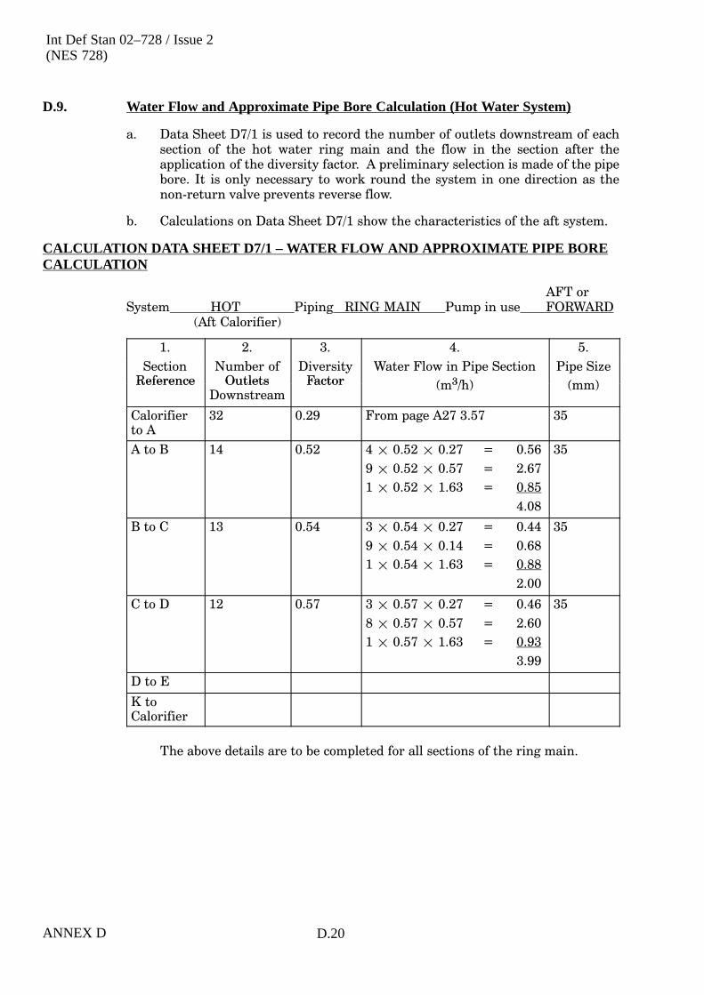
Int Def Stan 02–728 / Issue 2(NES 728)
ANNEX D D.20
D.9. Water Flow and Approximate Pipe Bore Calculation (Hot Water System)
a. Data Sheet D7/1 is used to record the number of outlets downstream of eachsection of the hot water ring main and the flow in the section after theapplication of the diversity factor. A preliminary selection is made of the pipebore. It is only necessary to work round the system in one direction as thenon�return valve prevents reverse flow.
b. Calculations on Data Sheet D7/1 show the characteristics of the aft system.
CALCULATION DATA SHEET D7/1 – WATER FLOW AND APPROXIMATE PIPE BORECALCULATION
AFT orSystem HOT Piping RING MAIN Pump in use FORWARD
(Aft Calorifier)
1.
S
2.
b f
3. 4.
l S
5.
SSectionReference
Number ofOutlets
DiversityFactor
Water Flow in Pipe Section
(m3/h)
Pipe Size
(mm)Reference OutletsDownstream
Factor (m3/h) (mm)
Calorifierto A
32 0.29 From page A27 3.57 35
A to B 14 0.52 4 � 0.52 � 0.27 = 0.56
9 � 0.52 � 0.57 = 2.67
1 � 0.52 � 1.63 = 0.85
4.08
35
B to C 13 0.54 3 � 0.54 � 0.27 = 0.44
9 � 0.54 � 0.14 = 0.68
1 � 0.54 � 1.63 = 0.88
2.00
35
C to D 12 0.57 3 � 0.57 � 0.27 = 0.46
8 � 0.57 � 0.57 = 2.60
1 � 0.57 � 1.63 = 0.93
3.99
35
D to E
K toCalorifier
The above details are to be completed for all sections of the ring main.

Int Def Stan 02–728 / Issue 2(NES 728)
ANNEX DD.21
D.10. Water Flow and Approximate Pipe Bore Calculation
a. Data Sheet D7/2 is used to record the water flow and initial selection of pipe borefor the hot water system branches on the aft system.
CALCULATION DATA SHEET D7/2 – WATER FLOW AND APPROXIMATE PIPE BORECALCULATION
AFT orSystem HOT Piping BRANCHES Pump in use FORWARD
1. 2. 3. 4. 5.
SectionReference
Number ofOutlets
Downstream
DiversityFactor
Water Flow in Pipe Section Pipe Size
(m3/h) (mm)
A to 1 17 0.46 11.0 � 0.46 � 0.27 = 1.37
1.0 � 0.46 � 0.57 = 0.26
5.0 � 0.46 � 0.14 = 0.32
1.95
28
1 to 2 11 0.57 11 � 0.57 � 0.27 = 1.69
1.69
28
B to 4 1 1.0 1 � 1 � 0.27 = 0.27 12
C to 5 1 1.0 1 � 1 � 0.57 = 0.57 15
D to 6
E to 7
F to 8
K to 13 1 1 1 � 1 � 0.57 = 0.57 15
The above details are to be completed from all Sections from the piping main.

Int Def Stan 02–728 / Issue 2(NES 728)
ANNEX D D.22
D.11. Physical Data (Hot Water System)
a. Data Sheet D8/1 is used to record the physical data for the hot water ring mainfor the aft hot water system.
CALCULATION DATA SHEET D8/1 – PHYSICAL DATA
AFT orSystem HOT Piping MAIN Pump in use FORWARD
(Aft Calorifier)
1.
Section
2.
Length
3.
Elbows
4.
Tee pieces
5.
Tee pieces
6.
Other
7.
Stop CocksSectionReference
Length(m)
Elbows Tee�pieces(Flow Past)
Tee�pieces(Flow Round)
OtherFittings
Stop Cocksand Valves
Calorifierto A
1.3 1 - - - 1
A to B 5.4 1 1 1 - -
B to C 2.4 - 1 1 - -
C to D 6.7 1 1 1 - -
D to E 21.2 2 1 - - -
E to F 0.6 - 1 - - -
F to G 6.7 1 1 1 - -
G to H 10.3 1 1 - - -
H to J 9.7 1 1 - - -
J to K 4.2 - 1 - - -
K toCalorifier
53.3 8 3 - - -
The above details are to be completed for all branches of the system.

Int Def Stan 02–728 / Issue 2(NES 728)
ANNEX DD.23
D.12. Physical Data for Hot Water Branches (Aft)
a. Data Sheet D8/2 is used to record the physical data for the hot water branches inthe aft hot water system.
CALCULATION DATA SHEET D8/2 – PHYSICAL DATA
AFT orSystem HOT Piping BRANCHES Pump in use FORWARD
(Aft Calorifier)
1. 2. 3. 4. 5. 6. 7.
SectionReference
Length(m)
Elbows Tee�pieces(Flow Past)
Tee�pieces(Flow Round)
OtherFittings
Stop Cocksand Valves
A to 1 5.8 3 1 - - 1
1 to 2 7.9 3 3 1 - -
1 to 3 5.5 3 1 1 - -
B to 4 3.0 2 - 1 - 1
C to 5 0.6 1 - 1 - 1
D to 6 3.0 1 1 1 - 1
E to 7 0.6 1 - 1 - 1
F to 8 6.1 4 - 1 - 1
F to 9 7.9 2 3 - - 1
G to 10 1.2 1 - 1 - 1
H to 11 3.0 3 1 1 - 1
J to 12 2.4 3 1 1 - 1
K to 13 2.4 1 - 1 - 1
The above details are to be completed for all branches of the system.
D.13. Pipe Friction Calculations (Hot Water System Main)
a. Data Sheet D9/1 is used to calculate the pressure drop around the aft hot watersystem ring main.
b. The procedure is the same as that used for the cold water system (see Annex D.).However, the pipe resistance is to be taken from Figure 1.11, and Clause 1.11.

Int Def S
tan 02–728 / Issue 2(N
ES
728)
AN
NE
X D
D.24
CALCULATION DATA SHEET D9/1 – PIPE FRICTION CALCULATIONS
AFT orSystem HOT Piping BRANCHES Pump in use FORWARD
(Aft Calorifier)
1.Section
2.Flow
3
3.System
4.Equivalent
5.Pipe
6.Component
7.Actual
8.Total
9.Water
10.Head
11.Section
12.Height
13.TotalSection
ReferenceFlow
(m3/h)System
ComponentsEquivalent
LengthCoefficient
K
PipeBore
D( )
ComponentEquivalent
Length
K D
ActualLength
(m)
TotalEquivalent
Length( )
Waterspeed(m/s)
Headloss
(bar/m)
Sectionloss
(bar)
HeightaboveDatum(b )
Totalloss tosection(b )K (mm)
g
K � D1000
� (m)(m) (bar) (bar)
Calorifierto A
3.57 ElbowsBall Valves
11
12 � 1 = 1215 � 1 = 15Total = 27
32 0.9 1.3 2.2 1.23 0.0044 0.0044� 2.2= 0.01
0 0.01
A to B 4.08 ElbowsTees (flow past)Tees (flow round)
111
12 � 1 = 12-120 � 1 = 120Total = 132
32 4.2 5.4 9.6 1.41 0.0055 0.0055� 9.6= 0.053
0.24 0.01+ 0.053+ 0.24= 0.303
B to C 4.09 Tees (flow past)Tees (flow round)
11
-70 � 1 = 70Total = 70
32 2.2 2.4 4.6 1.41 0.0056 0.0056� 4.6= 0.026
0.24 0.303+ 0.026= 0.329
C to D
D to E
J to K
The above details are to be completed for all sections of piping.

Int Def Stan 02–728 / Issue 2(NES 728)
ANNEX DD.25
D.14. Pipe Friction Calculations (Hot Water System Branches)
a. Data Sheet D9/2 is used to calculate the pressure drop in the aft hot watersystem branches.
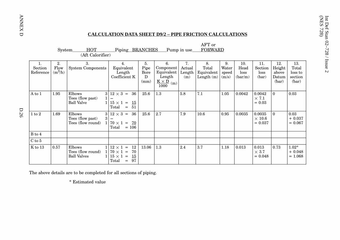
Int Def S
tan 02–728 / Issue 2(N
ES
728)
AN
NE
X D
D.26
CALCULATION DATA SHEET D9/2 – PIPE FRICTION CALCULATIONS
AFT orSystem HOT Piping BRANCHES Pump in use FORWARD
(Aft Calorifier)
1.Section
2.Flow
3
3.System Components
4.Equivalent
5.Pipe
6.ComponentE i l
7.Actual
8.Total
9.Water
10.Head
11.Section
12.Height
13.TotalSection
ReferenceFlow
(m3/h)System Components Equivalent
LengthCoefficient K
PipeBore
D( )
pEquivalent
LengthK � D
ActualLength
(m)
TotalEquivalentLength (m)
Waterspeed(m/s)
Headloss
(bar/m)
Sectionloss
(bar)
HeightaboveDatum(b )
Totalloss tosection(b )(mm) K � D
1000� (m) (bar) (bar)
A to 1 1.95 ElbowsTees (flow past)Ball Valve
311
12 � 3 = 36-15 � 1 = 15Total = 51
25.6 1.3 5.8 7.1 1.05 0.0042 0.0042� 7.1= 0.03
0 0.03
1 to 2 1.69 ElbowsTees (flow past)Tees (flow round)
331
12 � 3 = 36-70 � 1 = 70Total = 106
25.6 2.7 7.9 10.6 0.95 0.0035 0.0035� 10.6= 0.037
0 0.03+ 0.037= 0.067
B to 4
C to 5
K to 13 0.57 ElbowsTees (flow round)Ball Valves
111
12 � 1 = 1270 � 1 = 7015 � 1 = 15Total = 97
13.06 1.3 2.4 3.7 1.18 0.013 0.013� 3.7= 0.048
0.73 1.02*+ 0.048= 1.068
The above details are to be completed for all sections of piping.
* Estimated value

Int Def Stan 02–728 / Issue 2(NES 728)
ANNEX DD.27
D.15. Pressures Required and Available at Calorifier(s)
a. Data Sheet D10 is used to calculate the pressures that are required and areavailable at the aft calorifier.
b. The pressure loss to the most remote point of the system will have beencalculated on Data Sheet D9/-. To this must be added a 10% safety margin andthe pressure required at the outlet (0.35 bar) to give the pressure required at thecalorifier inlet.
c. The pressure available at the calorifier with either of the two pumps in use willhave been determined as part of the analysis of the cold water system.
d. Data Sheet D10 includes a section for determining the requirement for a hotwater boost pump. As stated in Clause 1.7.5a , a hot water boost pump is not tobe fitted unless its use is completely unavoidable. The following alternativearrangements are to be considered:
(1) The use of separate single outlet electric water heaters supplied from thecold water boost pump system.
(2) The use of separate hot water system supplied from the cold water boostpump.
e. Similar calculations are to be made for each of the hot water systems on theship.
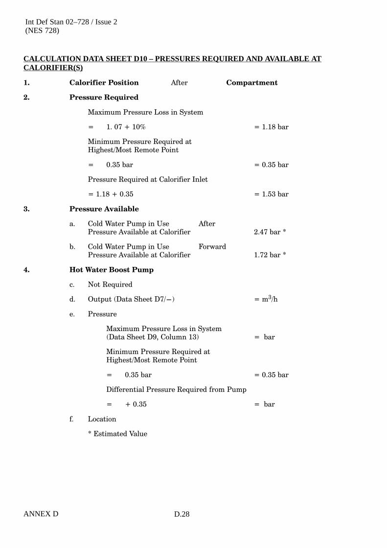
Int Def Stan 02–728 / Issue 2(NES 728)
ANNEX D D.28
CALCULATION DATA SHEET D10 – PRESSURES REQUIRED AND AVAILABLE ATCALORIFIER(S)
1. Calorifier Position After Compartment
2. Pressure Required
Maximum Pressure Loss in System
= 1. 07 + 10% = 1.18 bar
Minimum Pressure Required atHighest/Most Remote Point
= 0.35 bar = 0.35 bar
Pressure Required at Calorifier Inlet
= 1.18 + 0.35 = 1.53 bar
3. Pressure Available
a. Cold Water Pump in Use AfterPressure Available at Calorifier 2.47 bar *
b. Cold Water Pump in Use ForwardPressure Available at Calorifier 1.72 bar *
4. Hot Water Boost Pump
c. Not Required
d. Output (Data Sheet D7/-) = m3/h
e. Pressure
Maximum Pressure Loss in System(Data Sheet D9, Column 13) = bar
Minimum Pressure Required atHighest/Most Remote Point
= 0.35 bar = 0.35 bar
Differential Pressure Required from Pump
= + 0.35 = bar
f. Location
* Estimated Value

Int Def Stan 02–728 / Issue 2(NES 728)
ANNEX DD.29
D.16. Duty of Hot Water Circulating Pump
a. Data Sheet D11 is used to determine if a hot water circulating pump is required.
b. The vertical lift of the hot and cold legs of the hot water ring main is determinedfrom the arrangement drawings.
c. Clause 1.11.9b gives the maximum equivalent length of each size of pipethrough which it is possible to maintain adequate thermal circulation for eachmetre of vertical lift.
d. The equivalent length of the ring main is determined using the same proceduresas those used in Data Sheet D9. If the system total equivalent length is greaterthan can be sustained by the available vertical lift then a circulating pump is tobe fitted.
e. If a circulating pump is required it is to be capable of maintaining a water speedround the ring main to keep the main at the required temperature. Thepressure development required by the pump is determined by completingData Sheet D9 for the ring piping at the required circulation rate.
f. Similar calculations are to be made for each of the hot water systems on theship.
g. Details of the standard range hot water circulation pump are given inClause 1.7.4c .
h. The circulating rate required is determined from the formulae:
Heat�Loss �K�2�L�(T2���T1)
loge��r2r1
� kW
Where K = Thermal conductivity of piping insulation
= 2.3 � 10-5 kW/m2 °C/m thickness
L = Length of piping in metre
T1 = Hot water temperature = 70°C
T2 = Ambient temperature = 15°C
r1, r2 = Inside and outside radius of piping insulationin consistent units
Circulating�Rate � Heat�Loss5.81
� m3h

Int Def Stan 02–728 / Issue 2(NES 728)
ANNEX D D.30
CALCULATION DATA SHEET D11 – DUTY OF HOT WATER CIRCULATING PUMP
Calorifier After
Hot and cold leg vertical lift 4.9 m
Size of piping in ring main 34 mm
Maximum ring main equivalent length for natural circulation(see Clause 1.11.9b ) 4.9 � 25 = 122.5 m
Resistance of Ring Main
System Components EquivalentLength
Coefficient
Pipe Bore(mm)
ComponentEquivalentLength (m)
Bends 26 12 � 26 = 312612 � 32
Valves, ball 2 15 � 2 = 30612 � 32
1000
Valves, NR 1 60 � 1 = 60
Tees (flow round) 3 70 � 3 = 210 32 = 19.58
Tees (flow past) 7
612
TOTAL 19.58
Actual Pipe Length (see Data Sheet D 8/1) 121.8
Total Equivalent System Length 141.38
Natural circulation not possible
Hot Water Circulating Pump
Circulation rate �Heat�loss�(kW)
5.81�
K � 2�� L�(T2���T1)
loge�r2r1� 5.81
�2.3 � 10�5 � 2�� 121.8 � (70� �� 15)
loge�36.517.5
� 5.81� � 0.23m3h
D.17. Capacity of Accumulators
a. Data Sheet D12 is used for the selection of accumulators; one accumulator is tobe used in each hot water system. A separate Data Sheet is to be used for theselection of each accumulator.
b. The volume of the water in the ring main and calorifier is to be determined. Pipecapacity may be taken from Table 1.4. Clause 1.11. Data Sheet D11 gives thevolume of the calorifier.
c. The required capacity of the accumulator is 5% of the total ring main plus thecalorifier capacity.
d. Details of standard range accumulators are given in Clause 1.10.

Int Def Stan 02–728 / Issue 2(NES 728)
ANNEX DD.31
CALCULATION DATA SHEET D12 – CAPACITY OF ACCUMULATORS
Calorifier After
1. Volume of water in ring main
Pipe Bore Pipe Length Weight of Water Total Weight of Waterp
(mm)
p g
(m)
g
(kg/m)
g
(kg)
32 121.8 0.81 98.7
98.7
Total volume, Weight � 1000 m3 = 0.099 m3
Calorifier volume = 0.200 m3 *
Total system volume 0.299 m3
2. Capacity of Accumulator
The accumulator capacity is to be 5% of the total
Capacity required = 0.299 m3 � 5% = 0.015 m3
* Estimated value

Int Def Stan 02–728 / Issue 2(NES 728)
ANNEX D D.32

Int Def Stan 02–728 / Issue 2(NES 728)
INDEX 1
ALPHABETICAL INDEX
(NOTE: Page numbers are given)
AAccumulators
capacity: 1.45; D.1
design requirements: 1.45
location in system: 1.10
table of available units: 1.25
type: 1.24
Aerating arrangements: 1.14
Air escapes, storage tanks: 1.16
Air pressure charging equipment, Submarinetanks: 1.25
Air release units: 1.25
Air removal: 1.45, 1.46
Allowances, daily consumption: 1.4
BBattery top-up water, Submarines: 1.4
Brazing requirements: 3.6
Bridge window washers: 1.4, 1.7
CCalculations
capacity of accumulators: D.30
data sheet instructions: D.1
general requirements: D.1
introduction: D.8
physical data, cold water system: D.8
physical data, hot water system: D.23
pipe friction, cold water system: D.1, D.8
pipe friction, hot water system: D.23
pressures at calorifier: D.27
selections of, cold water pumps: D.17
selections of, hot water pumps: D.29
water flow and pipe bore, cold watersystem: D.5
water flow and pipe bore, hot water system: D.21
water flow rates from calorifiers: D.19
Calibration of tanks: 1.49; 3.7
Calorifiers
general purpose, heat source: 1.11
general purpose, heating capacity: 1.4,1.37
general purpose, pressures required: D.27
general purpose, requirements: 1.23
general purpose, selection: 1.37
general purpose, sizing: 1.38
general purpose, types: 1.22
general purpose, water flow rates: D.19
general purpose, water supply to: 1.9
Submarines: 1.23
Submarines, preferred range: 1.23
Casting requirements: 3.6
Chambers, air: 1.7
Cleaning
fresh water storage tanks: 3.7
general requirements: 3.7
tubes and pipes: 3.7
Cocks, push: 1.3; 3.2, 3.5
Cold water
emergency supply to sonar cooling: 1.12;3.4
filling arrangements, Submarines: 1.14,1.15
filling arrangements, HM Surface Ships:1.13, 1.14
pumps, capacity: 1.33
pumps, general requirements: 1.16, 1.19
storage tank, arrangements, Submarines:1.13; 4.3
storage tank, arrangements, HM SurfaceShips: 1.13
storage tank, cleaning: 3.7
storage tank, design: 1.13; 3.6
storage tank, manufacturer: 3.6
submarine services supplied: 4.2
surface ship services supplied: 3.2, 3.3;4.1, 4.2
system arrangement, Submarines: 1.8, 1.9
system arrangement, HM Surface Ships:1.4, 1.5, 1.7, 1.8; 3.3
system design procedure: 1.26, 1.27, 1.28,1.31, 1.32
Colours and marking: 1.51; 2.1; 3.8

Int Def Stan 02–728 / Issue 2(NES 728)
INDEX 2
Connections
hose, filling: 1.14
hose, pumps: 1.5
piping: 3.4, 3.5
Cooled fresh water
equipment: 1.24
supply: 1.24
Cross connection, hot water systems: 1.9
DDeck connections: 1.14
Desalination requirements
general: 1.12; 3.4
Submarines: 1.12
HM Surface Ships: 1.12; 3.4
Design review: 1.32
Diversity factors for outlets: 1.32
Drawings
diagrammatic arrangement: 1.1; 3.1
equipment: 1.2
DPA guidance: 3.1
preparation and general requirements: 3.1
ship arrangement: 1.2
supplied by manufacturer: 3.1
supplied by shipbuilder: 3.1
symbols to be used: 3.1
systems: 3.1
Drinking water
coolers: 1.24
tanks: 1.23, 1.24
EElectric water heaters: 1.45
Emergency supply
cabinets: 1.7
sonar cooling system: 1.12; 3.4
Emergency water tanks: 1.24
Equivalent pipe lengths for fittings: 1.28
FFilling and transfer lines: 1.5
Filling arrangementsSubmarines: 1.14, 1.15HM Surface Ships: 1.13, 1.14
Filling funnels: 1.14
Filling rates, HM Surface Ships: 1.13
Fittingsdischarge rate: 1.32for sterilization: 1.15
Flangesgeneral requirements: 1.25materials: 1.3; 3.1, 3.2
Flexible assemblies: 1.7; 3.3
Flushing of system: 3.7
Freezing, precautions against: 1.7
Fresh water filling arrangements: 1.13, 1.14,1.15
Fresh water sterilization: 1.15
Fresh water storage tanksarrangements: 1.13; 4.3cleaning and preservation: 3.7materials: 1.3; 2.1; 3.1pressure tests: 1.49, 1.50; 3.7, 3.8
Frost plugs: 1.7
GGauges, tank contents: 1.14, 1.15
HHeat emission from piping: 1.37
Heaterselectric water: 1.45local: 1.11
Heatingcapacity: 1.22equipment: 1.22
Hosecleanliness precautions: 1.14filling connections: 1.14
Hot water
pumps, duty: D.29pumps, general requirements: 1.19services supplied, Submarines: 1.4; 4.3services supplied, HM Surface Ships: 3.3;
4.3storage capacity: 1.38, 1.39system arrangement, Submarines: 1.11,
1.12system arrangement, HM Surface Ships:
1.9, 1.10, 1.11

Int Def Stan 02–728 / Issue 2(NES 728)
INDEX 3
system, circulation: 1.10, 1.37
system, peak load: 1.38
IInspection: 3.7
Installation
flexibility: 1.47
general requirements: 1.47, 1.48; 3.7
Insulation
material: 3.2
pipework: 1.50; 3.8
JJointing
general requirements: 3.5
material: 3.2
LLadders in storage tanks: 1.3, 1.13; 2.1
MManholes, tank access: 1.13
Manufacturing practices, generalrequirements: 3.5
Materials
accumulators: 1.3
calorifiers: 3.1
fresh water storage tanks: 1.3; 2.1; 3.1
insulation: 3.2
jointing: 3.2
pipe clips: 1.2; 2.1
pipework, non-ferrous: 1.3; 3.1
pipework, steel: 1.3; 3.2
pumps: 3.1
screwed fasteners: 3.2
selection: 1.2; 3.1
valves and cocks: 1.3; 3.2
Maximum water speeds: 1.27
Medical compartment, water heaterrequirements: 1.23
OOrifice
in supply to taps and showers: 1.35
preferred range: 1.35
pump leak-off: 1.22
Overpressure, protection against duringfilling: 1.14
PPhotographic section, cooled water unit:
1.24
Physical data calculations
cold water system: D.8
hot water system: D.24
Pipe
cleaning: 3.7
friction calculations: D.10
manipulation: 3.6
materials: 1.3; 3.1, 3.2
Piping
colours and markings: 1.51; 2.1; 3.8
connections: 3.4, 3.5
general requirements: 1.25
in fresh water tanks: 1.3; 3.2
installation: 1.47, 1.48, 1.49; 3.7
insulation: 1.50; 3.8
jointing: 1.25
trials: 1.50
within containment boundary, Submarines: 1.50
Preservation
fresh water storage tanks: 3.7
general requirements: 3.7
tubes and pipes: 3.7
Pressure
at highest point in HM Surface Ships: 1.4
at outlets: 1.35
indicators: 1.5
loss: 1.28
operating, Submarines: 1.9
operating, HM Surface Ships: 1.33
tests: 1.49, 1.50; 3.7, 3.8
Pumps
cold water boost: 1.19, 1.35
cold water circulating: 1.16, 1.33
general requirements: 1.16; 3.4
hot water boost: 1.22

Int Def Stan 02–728 / Issue 2(NES 728)
INDEX 4
hot water circulating: 1.19
protection: 1.22
Purity standard for fresh water: 1.3
Push cocks
application: 3.5
material: 1.3; 3.2
Pyrotechnic locker flooding requirements:1.9
SScrewed fasteners: 1.25; 3.2
Services, essential for HM Surface Ships: 1.7
Showers
flow rate: 1.32
provision of: 3.3; 4.3
supplies to: 1.32
Sonar cooling system, emergency supply:1.12; 3.4
Sounding tubes: 1.15; 4.3
Steam/water mixers: 1.23
Sterilisation fittings: 1.15
Storage tank calibrations: 1.49; 3.7
Strainers
for special equipment: 1.7
general requirements: 3.5
pump suction: 1.5; 3.3
Symbols on drawings: 3.1
System
boost: 1.8
boost, cold water: 1.8
boost, hot water: 1.11
cold water, services supplied: 3.2, 3.3;4.1, 4.2
design objectives: 1.3, 1.4; 3.2
design procedure: 1.26, 1.27, 1.28, 1.31,1.32
design review: 1.32
hot water, services supplied: 1.4; 3.3; 4.3
Submarines: 1.9
Submarines, HM Surface Ships: 1.33
pressure at outlets: 1.35
System arrangement
cold water: 1.4
cold water, Submarines: 1.8, 1.9
cold water, HM Surface Ships: 1.4, 1.5,1.7, 1.8; 3.3
hot water: 1.9
hot water, Submarines: 1.11, 1.12
hot water, HM Surface Ships: 1.9, 1.10,1.11
TTanks
construction: 1.13
drinking water: 1.23, 1.24
emergency fresh water: 1.24
fresh water storage, Submarines: 1.8
fresh water storage, HM Surface Ships:1.4
Taps, flow rate: 1.32
Thermo-syphon circulation: 1.10, 1.36
Trials: 1.50
VValves
automatic air release: 1.25
ball: 1.24; 3.5
bulkhead and containment boundary: 1.9
general requirements: 3.5
isolating, location: 1.7
materials: 1.3
pressure tests: 1.50
working pressure: 1.50
WWash-basins
flow rate: 1.32
provision of: 3.3; 4.3
supplies to: 1.32
Washers, bridge window: 1.4, 1.7
Water
cooled: 1.24
heaters, electric: 1.45
purity standard: 1.3
speeds, maximum: 1.27
Welding requirements: 3.5
Welds, inspection of storage tanks: 3.6

Inside Rear Cover
© Crown Copyright 2000
Copying Only as Agreed with DStan
Defence Standards are Published by and Obtainable from:
Defence Procurement AgencyAn Executive Agency of The Ministry of Defence
UK Defence StandardizationKentigern House65 Brown Street
GLASGOW G2 8EX
DStan Helpdesk
Tel 0141 224 2531/2 Fax 0141 224 2503
Internet e-mail [email protected]
File Reference
The DStan file reference relating to work on this standard is D/DStan/069/02/728.
Contract Requirements
When Defence Standards are incorporated into contracts users are responsible for their correctapplication and for complying with contractual and statutory requirements. Compliance witha Defence Standard does not in itself confer immunity from legal obligations.
Revision of Defence Standards
Defence Standards are revised as necessary by up issue or amendment. It is important thatusers of Defence Standards should ascertain that they are in possession of the latest issue oramendment. Information on all Defence Standards is contained in Def Stan 00-00 Standardsfor Defence Part 3 , Index of Standards for Defence Procurement Section 4 ‘Index of DefenceStandards and Defence Specifications’ published annually and supplemented regularly byStandards in Defence News (SID News). Any person who, when making use of a DefenceStandard encounters an inaccuracy or ambiguity is requested to notify UK DefenceStandardization (DStan) without delay in order that the matter may be investigated andappropriate action taken.