Embed Size (px)
DESCRIPTION
Technical report explaining the material choices made and the structutal developments undertook to ensure the end product suited the needs of the consumer, whilst also adhering to existing standards.
Citation preview

1
TechMaterials, Structural Development
Voronoi Structure
2
TechVoronoi Structure
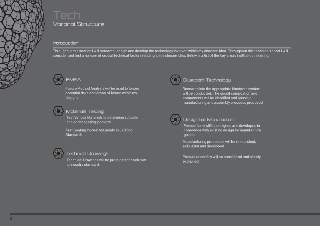
Throughout this section I will research, design and develop the technology involved within my choosen idea. Throughout this technical report I will consider and test a number of crucial technical factors relating to my chosen idea. Below is a list of the key areas i will be considering:
Introduction
FMEA
Failure Method Analysis will be used to forsee potential risks and areas of failure within my designs
Materials Testing
Test Seating Pocket MAterials to Existing Standards
Test Various Materials to determine sutiable choice for seating pockets
Bluetooth Technology
Research into the appropriate bluetooth system will be conducted. The circuit compostion and components will be identified and possible manufacturing and assembly proccess proposed
Design for Manufacture
Manufacturing processes will be researched, evaluated and developed
Product form will be designed and developed in coherence with existing design for manufacture guides.
Technical Drawings
Technical Drawings will be produced of each part to industry standard.
Product assembly will be considered and clearly explained

3
4
TechMaterials Testing
The product incorporates a unique aspect within its form, ‘seating pockets’. The pockets will aloow the user to deform the material under their own weight producing a comfortable and pleasurable seating position. To ensure this physical pleasure is installed within each user of the product, the material selection is crucial. Throughout the testing of materials for the seating pockets, a number of factors must be considered. The product will be situated within pubic spaces, leaving it exposed to the elements and the general public for the entirity fo the year. The material choosen will need to be durable (withstand UV and all weather conditions) whilst also able to deform in an elastic way to ensure comfort for the user.
Things to Consider:
Material Used
Material properties must allow for suitable deformation when the user ‘sits’ within the material (comfort) whilst maintaining its structural integrity.
Material must return to its original form when force of the user is releived.
Material must resisit damge form the external elements.
Material must be readily availale and relatively cost effective.
Seating Pocket
To allow the seating pocket material to deform in a suitble way and support the user in a comfortable seating position, it needs to be securely attached the the structure.
Things to consider-
Material Attachment-
The mechanism chosen to attach the material to the frame must suitably spread the load of the user ensuring that the material is not exposed to over stress at the attachment points and innevitably fail.
The mechansim should be simple and use a minimum number of parts to keep cost of manufacture to a minimum.
Material Attachment Mechanism
5
TechMaterials Testing
The structure itself will be succeptble to large amounts of impact and resting force on a daily basic,the structure will need to support the total cimbined weight of the users when in use. The surface will be exposed to the elemenets for extended perods of time, whilst alsol potentially being exposed to intential damage. To ensure that I select a suitable, successful material for the main structure I will need to consider a number of varying factors:
Material selected must be able to be manufactured using existing technologies.
Material selected must successfully support the combined weight of users without fail, Engineer structure to cope with ‘worst case scenario’.
Material selected must be resistant to UV, water and other potentially damaging chemicals produced by the elements.
Voronoi Structure
6
TechMaterials Testing
To ensure my prodcut is accepted and passes the necessary validation, I will test each material used within my product against existing material standards. I will be taking standards from BS EN 1176-1:2008 Playground equipment and surfacing —Part 1: General safety requirements and test methods. The relevant standards I will be testing against are listed below:
Materials shall be selected and protected such that the structural integrity of the equipment manufactured from them is not affected before the next relevant maintenance inspection.
The selection of materials and their use should be in accordance with appropriate European Standards.
Special attention should be given to surface coatings to avoid potential toxic hazards.
The choice of materials should be appropriate where extreme climatic or atmospheric conditions are to be expected.
Where very low or very high temperatures can be anticipated care should be taken on material selection to avoid possible hazards through direct skin contact.
To avoid the risk of fire and associated hazards, materials known to produce surface flash shall not be used. Particular attention should be given to newly developed products whose properties might not be fully known.
Existing Material Standards
As well as testing the materials to existing standards, I will also consider additional material constraints that are more specified towards my product and its function. the list below outlines these tests:
Materials should resist intentional damage, materials will be tested to ensure resistance knife and flame damages.
Materials will be tested for durability. seating pocket material will be exposed to the elements and tested for structural integrity.
Additional Material Testing Consinderations
7
TechMaterials Testing
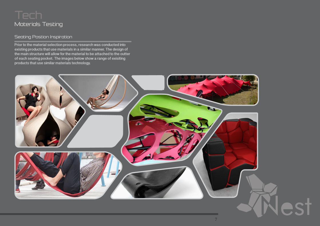
Prior to the material selection process, research was conducted into existing products that use materials in a similar manner. The design of the main structure will allow for the material to be attached to the outter of each seating pocket. The images below show a range of exisiting products that use similar materials technology.
Seating Postion Inspiration
8
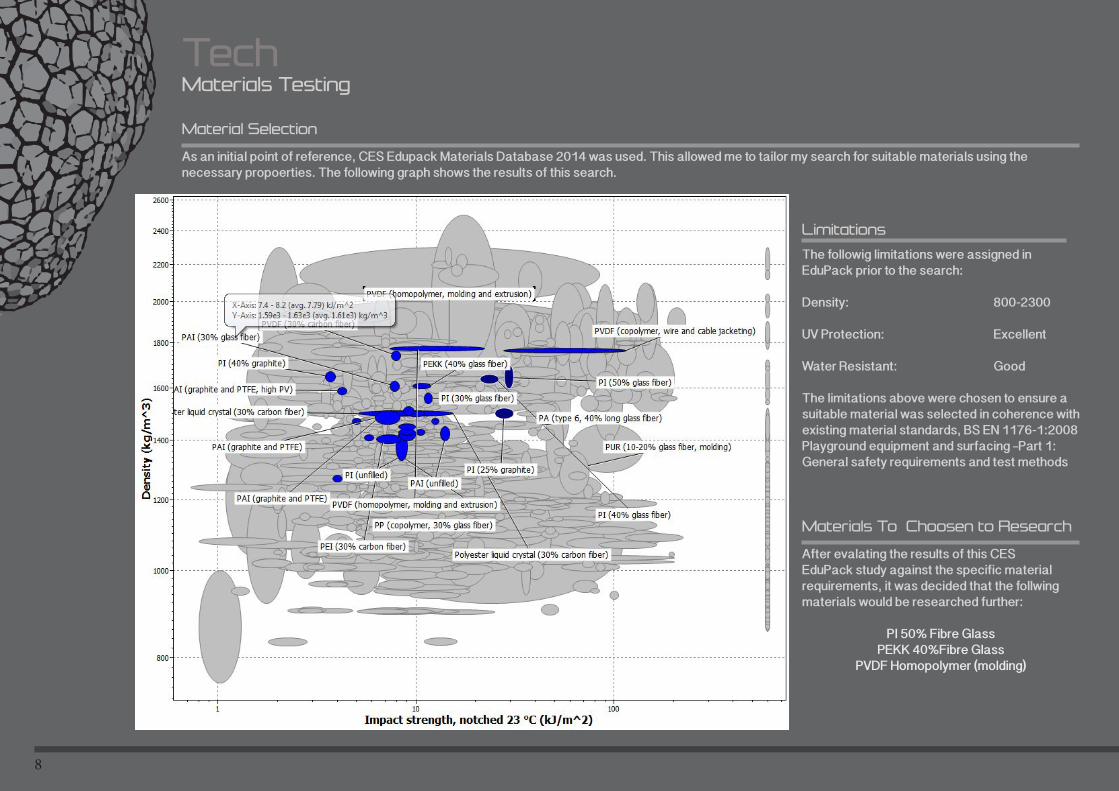
TechMaterials Testing
As an initial point of reference, CES Edupack Materials Database 2014 was used. This allowed me to tailor my search for suitable materials using the necessary propoerties. The following graph shows the results of this search.
Material Selection
Limitations
Materials To Choosen to Research
The followig limitations were assigned in EduPack prior to the search:
Density: 800-2300
UV Protection: Excellent
Water Resistant: Good The limitations above were chosen to ensure a suitable material was selected in coherence with existing material standards, BS EN 1176-1:2008 Playground equipment and surfacing —Part 1: General safety requirements and test methods
After evalating the results of this CES EduPack study against the specific material requirements, it was decided that the follwing materials would be researched further:
PI 50% Fibre GlassPEKK 40%Fibre Glass
PVDF Homopolymer (molding)
9
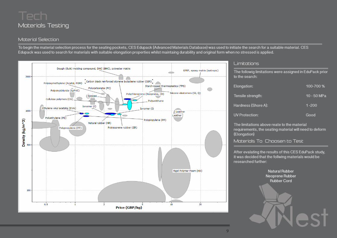
To begin the material selection process for the seating pockets, CES Edupack (Advanced Materials Database) was used to initiate the search for a suitable material. CES Edupack was used to search for materials with suitable elongation properties whilst maintaing durability and original form when no stressed is applied.
Material Selection
Materials To Choosen to Test
TechMaterials Testing
Limitations
The followig limitations were assigned in EduPack prior to the search:
Elongation: 100-700 %
Tensile strength: 10 - 50 MPa
Hardness (Shore A): 1 -200
UV Protection: Good
The limitations above reate to the material requirements, the seating material will need to deform (Elongation)
After evalating the results of this CES EduPack study, it was decided that the follwing materials would be researched further:
Natural RubberNeoprene Rubber
Rubber Cord
10
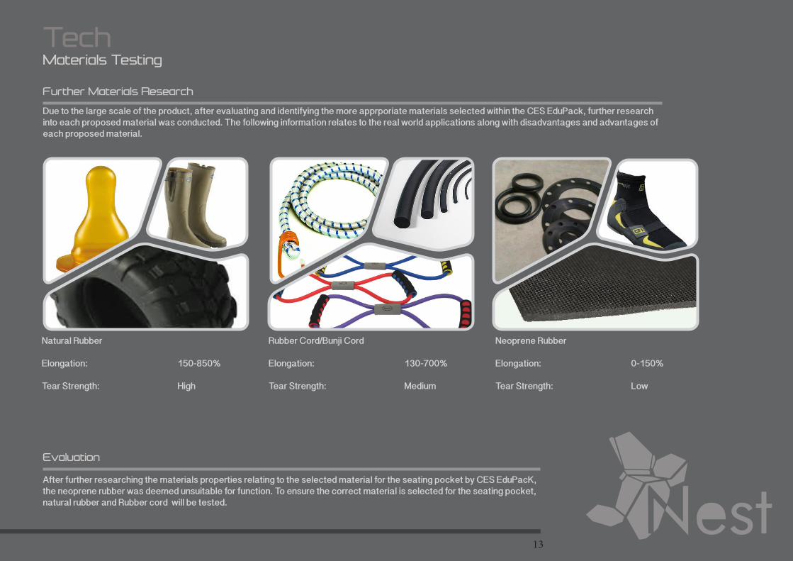
TechMaterials Testing
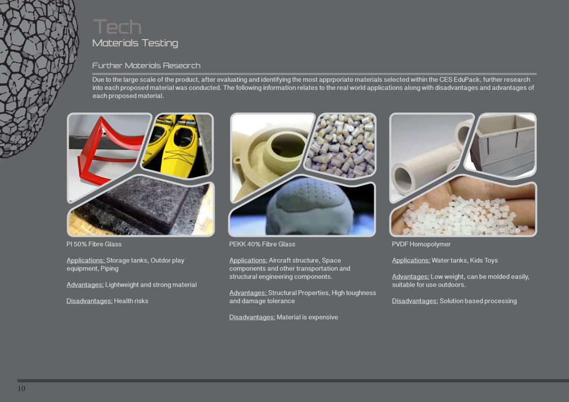
Due to the large scale of the product, after evaluating and identifying the most apprporiate materials selected within the CES EduPack, further research into each proposed material was conducted. The following information relates to the real world applications along with disadvantages and advantages of each proposed material.
Further Materials Research
PI 50% Fibre Glass
Applications: Storage tanks, Outdor play equipment, Piping
Advantages: Lightweight and strong material
Disadvantages: Health risks
PEKK 40% Fibre Glass
Applications: Aircraft structure, Space components and other transportation and structural engineering components.
Advantages: Structural Properties, High toughness and damage tolerance
Disadvantages: Material is expensive
PVDF Homopolymer
Applications: Water tanks, Kids Toys
Advantages: Low weight, can be molded easily, suitable for use outdoors.
Disadvantages: Solution based processing
11
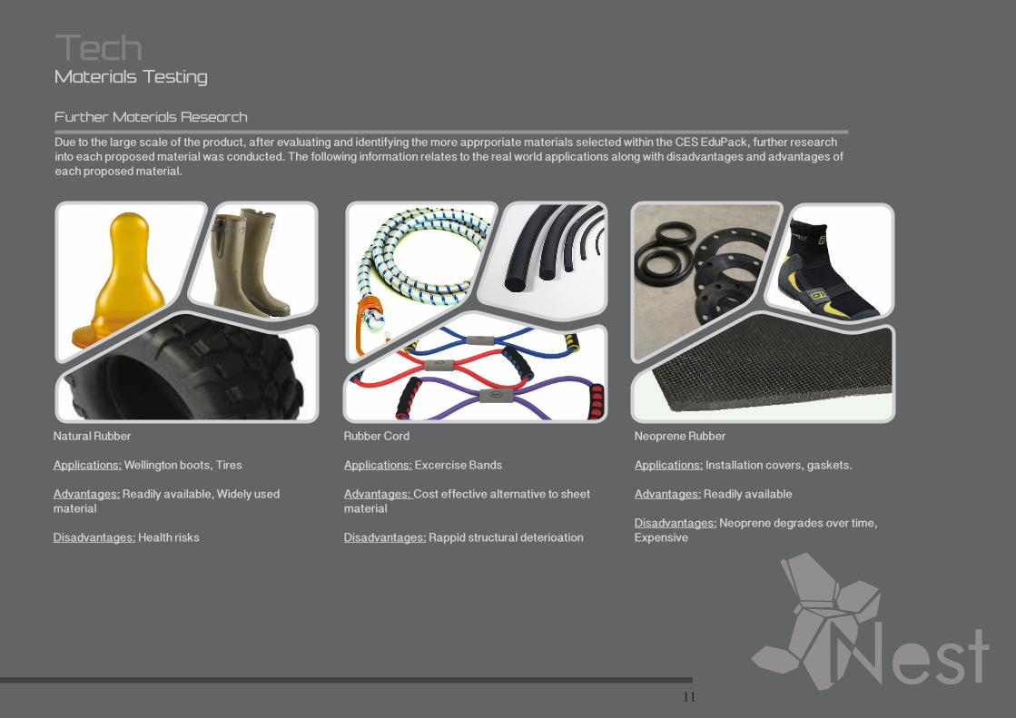
TechMaterials Testing
Due to the large scale of the product, after evaluating and identifying the more apprporiate materials selected within the CES EduPack, further research into each proposed material was conducted. The following information relates to the real world applications along with disadvantages and advantages of each proposed material.
Further Materials Research
Natural Rubber
Applications: Wellington boots, Tires
Advantages: Readily available, Widely used material
Disadvantages: Health risks
Rubber Cord
Applications: Excercise Bands
Advantages: Cost effective alternative to sheet material
Disadvantages: Rappid structural deterioation
Neoprene Rubber
Applications: Installation covers, gaskets.
Advantages: Readily available
Disadvantages: Neoprene degrades over time, Expensive
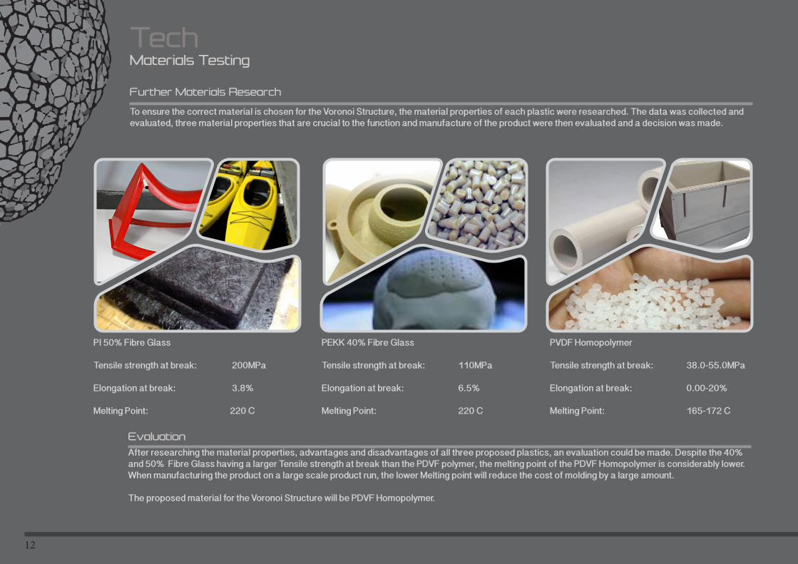
12
TechMaterials Testing
To ensure the correct material is chosen for the Voronoi Structure, the material properties of each plastic were researched. The data was collected and evaluated, three material properties that are crucial to the function and manufacture of the product were then evaluated and a decision was made.
Further Materials Research
PI 50% Fibre Glass
Tensile strength at break: 200MPa
Elongation at break: 3.8%
Melting Point: 220 C
PEKK 40% Fibre Glass
Tensile strength at break: 110MPa
Elongation at break: 6.5%
Melting Point: 220 C
PVDF Homopolymer
Tensile strength at break: 38.0-55.0MPa
Elongation at break: 0.00-20%
Melting Point: 165-172 C
After researching the material properties, advantages and disadvantages of all three proposed plastics, an evaluation could be made. Despite the 40% and 50% Fibre Glass having a larger Tensile strength at break than the PDVF polymer, the melting point of the PDVF Homopolymer is considerably lower. When manufacturing the product on a large scale product run, the lower Melting point will reduce the cost of molding by a large amount.
The proposed material for the Voronoi Structure will be PDVF Homopolymer.
Evaluation
13
TechMaterials Testing
Due to the large scale of the product, after evaluating and identifying the more apprporiate materials selected within the CES EduPack, further research into each proposed material was conducted. The following information relates to the real world applications along with disadvantages and advantages of each proposed material.
Further Materials Research
Natural Rubber
Elongation: 150-850%
Tear Strength: High
Rubber Cord/Bunji Cord
Elongation: 130-700%
Tear Strength: Medium
Neoprene Rubber
Elongation: 0-150%
Tear Strength: Low
After further researching the materials properties relating to the selected material for the seating pocket by CES EduPacK, the neoprene rubber was deemed unsuitable for function. To ensure the correct material is selected for the seating pocket, natural rubber and Rubber cord will be tested.
Evaluation
14
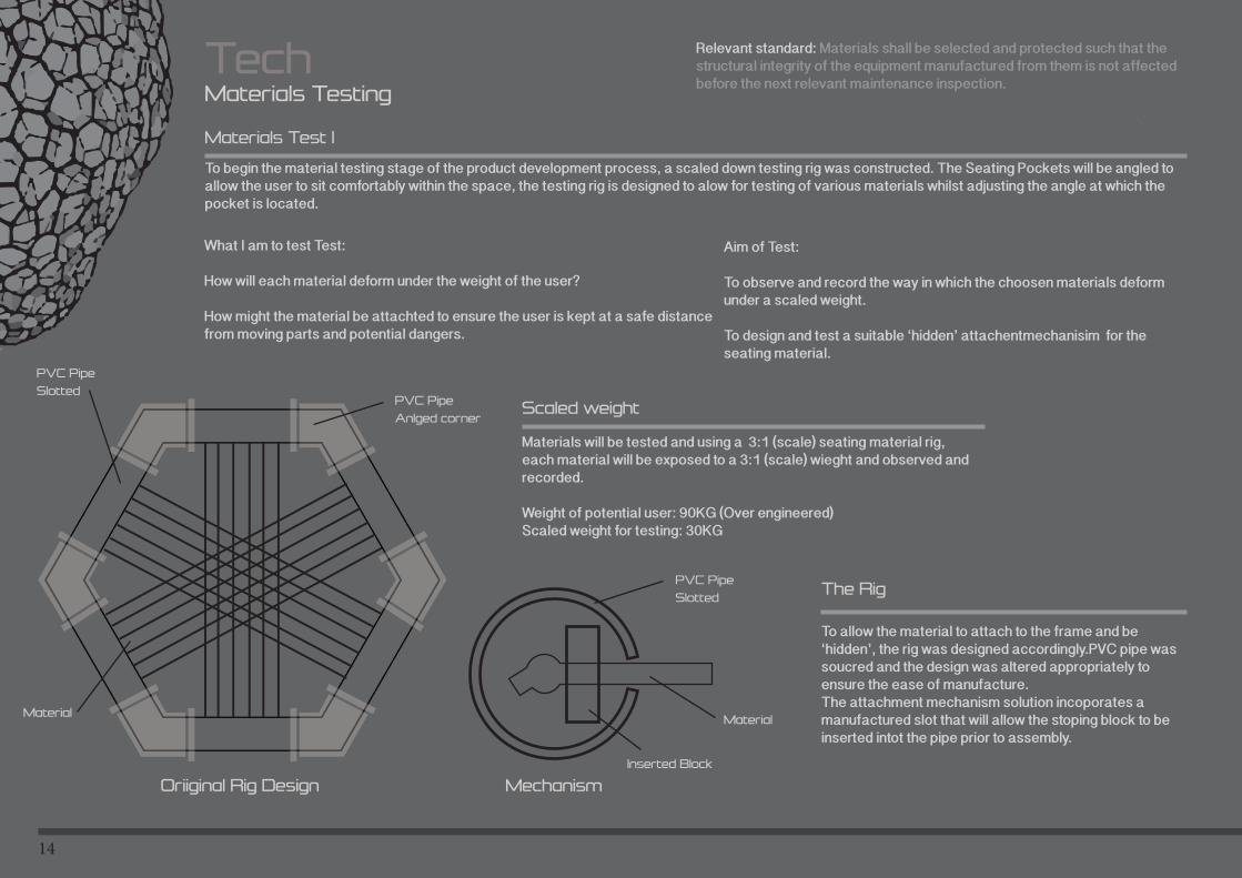
TechMaterials Testing
To begin the material testing stage of the product development process, a scaled down testing rig was constructed. The Seating Pockets will be angled to allow the user to sit comfortably within the space, the testing rig is designed to alow for testing of various materials whilst adjusting the angle at which the pocket is located.
Materials Test 1
Materials will be tested and using a 3:1 (scale) seating material rig, each material will be exposed to a 3:1 (scale) wieght and observed and recorded.
Weight of potential user: 90KG (Over engineered)Scaled weight for testing: 30KG
Scaled weight
Aim of Test:
To observe and record the way in which the choosen materials deform under a scaled weight.
To design and test a suitable ‘hidden’ attachentmechanisim for the seating material.
What I am to test Test:
How will each material deform under the weight of the user?
How might the material be attachted to ensure the user is kept at a safe distance from moving parts and potential dangers.
Relevant standard: Materials shall be selected and protected such that the structural integrity of the equipment manufactured from them is not affected before the next relevant maintenance inspection.
To allow the material to attach to the frame and be ‘hidden’, the rig was designed accordingly.PVC pipe was soucred and the design was altered appropriately to ensure the ease of manufacture. The attachment mechanism solution incoporates a manufactured slot that will allow the stoping block to be inserted intot the pipe prior to assembly.
The Rig
Oriiginal Rig Design Mechanism
Inserted Block
PVC Pipe
Slotted
Material
PVC Pipe
SlottedPVC Pipe
Anlged corner
Material
15
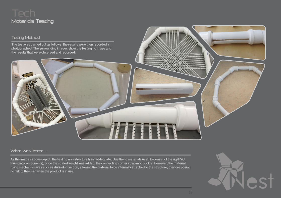
TechMaterials Testing
The test was carried out as follows, the results were then recorded a photographed. The surrounding images show the testing rig in use and the results that were observed and recorded.
Tesing Method
As the images above depict, the test rig was structurally innaddequate. Due the to materials used to construct the rig (PVC Plumbing components), once the scaled weight was added, the connecting corners began to buckle. However, the material fixing mechanism was successful in its function, allowing the material to be internally attached to the structure, therfore posing no risk to the user when the product is in use.
What was learnt......
16
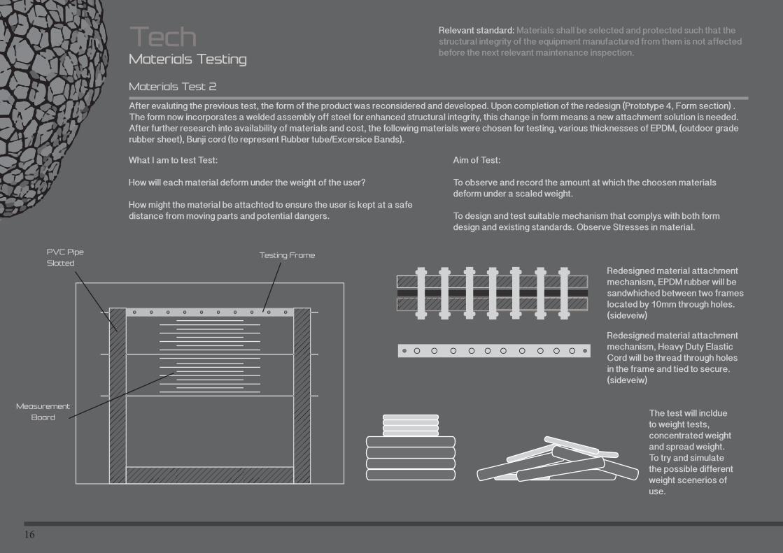
Materials Testing
After evaluting the previous test, the form of the product was reconsidered and developed. Upon completion of the redesign (Prototype 4, Form section) . The form now incorporates a welded assembly off steel for enhanced structural integrity, this change in form means a new attachment solution is needed. After further research into availability of materials and cost, the following materials were chosen for testing, various thicknesses of EPDM, (outdoor grade rubber sheet), Bunji cord (to represent Rubber tube/Excersice Bands).
Materials Test 2
Aim of Test:
To observe and record the amount at which the choosen materials deform under a scaled weight.
To design and test suitable mechanism that complys with both form design and existing standards. Observe Stresses in material.
What I am to test Test:
How will each material deform under the weight of the user?
How might the material be attachted to ensure the user is kept at a safe distance from moving parts and potential dangers.
Relevant standard: Materials shall be selected and protected such that the structural integrity of the equipment manufactured from them is not affected before the next relevant maintenance inspection.
PVC Pipe
SlottedTesting Frame
Measurement
Board
Redesigned material attachment mechanism, EPDM rubber will be sandwhiched between two frames located by 10mm through holes.(sideveiw)
Redesigned material attachment mechanism, Heavy Duty Elastic Cord will be thread through holes in the frame and tied to secure.(sideveiw)
The test will incldue to weight tests, concentrated weight and spread weight. To try and simulate the possible different weight scenerios of use.
Tech
17
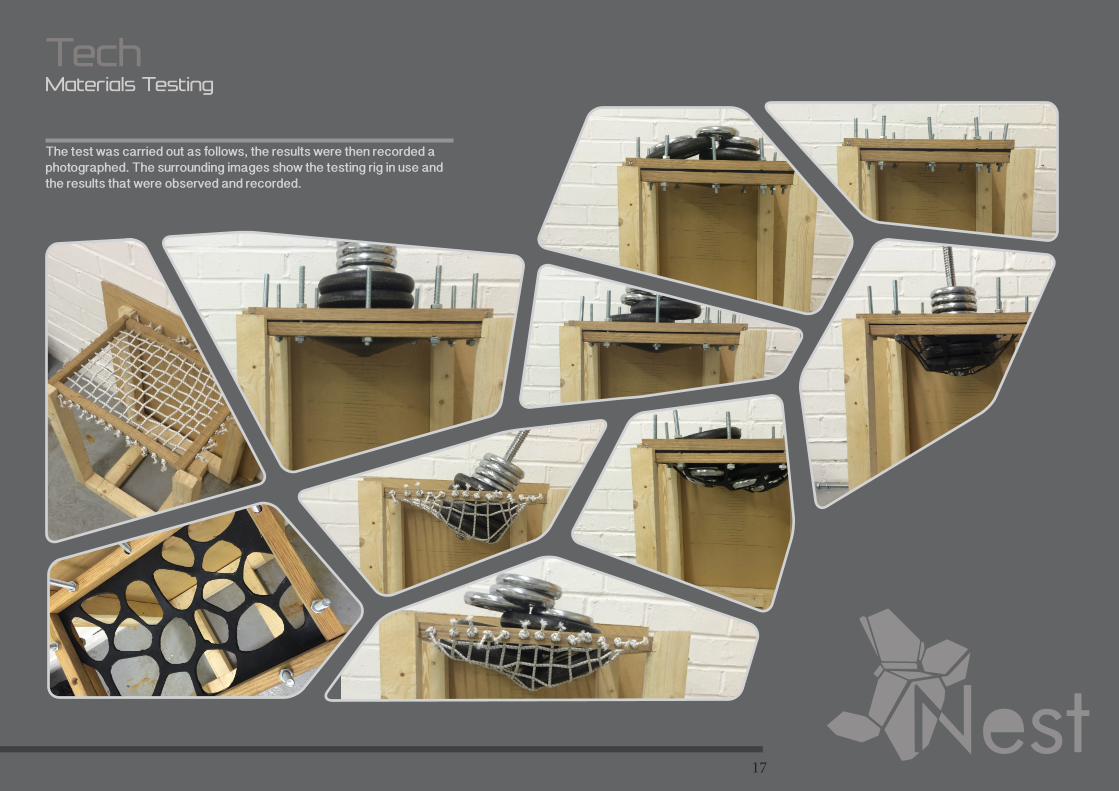
TechMaterials Testing
The test was carried out as follows, the results were then recorded a photographed. The surrounding images show the testing rig in use and the results that were observed and recorded.
18
Materials Testing
Below are the results of Materials Test 1. Each material was tested using concentraded weight and spread weight, to try and simulate the different scenarios of the product function.
Test Results
Tech
Bunji
2001 2005 2010
165
70
70
mm mm %
120
50
65
70
85
100
30
80
100
130125
5mm EPDM
3mm EPDM
4mm EPDM
5mm EPDM
3mm EPDM
4mm EPDM
Pattern Cut out
Pattern Cut out
Pattern Cut out
Spread WeightConcentrated
Weight Difference
40
20
15
40
5
0
5
Whilst conducting the test, obvservations were made. The flat EPDM sheets deformation under the scaled weight was inaddequate. The decision was made to include a Voronoi inspired pattern to decrease the surface area and allow for further deformation of the rubber.
Test Adjustments
19
Materials Testing
Tech
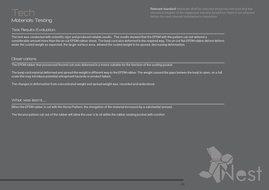
Test Results Evaluation
Observations
What was learnt......
The test was conducted with scientific rigor and produced reliable results. The results showed that the EPDM with the pattern cut-out defored a considerable amount more than the un-cut EPDM rubber sheet. The bunji cord also deformed in the required way. The un-cut flat EPDM rubber did not deform under the scaled weight as expected, the larger surface area, allowed the scaled weight to be spread, decreasing deformation.
Relevant standard: Materials shall be selected and protected such that the structural integrity of the equipment manufactured from them is not affected before the next relevant maintenance inspection.
The EPDM rubber that possessed Voronoi cut-outs deformed in a monor suitable for the function of the seating pocket.
The bunji cord material deformed and spread the weight in different way to the EPDM rubber. The weight caused the gaps betwen the bunji to open, on a full scale this may introduce potential entrapment hazards or product failure.
The changes in deformation from concentrated weight and spread weight was recorded and understood.
When the EPDM rubber is cut with the Vornoi Pattern, the elongation of the material increases by a substantial amount.
The Voronoi pattern cut-out of the rubber will allow the user is to sit within the rubber seating pocket with comfort.
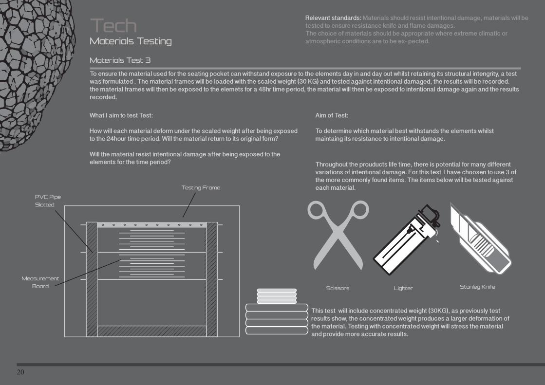
20
PVC Pipe
Slotted
Testing Frame
Measurement
Board
This test will include concentrated weight (30KG), as previously test results show, the concentrated weight produces a larger deformation of the material. Testing with concentrated weight will stress the material and provide more accurate results.
Materials Testing
To ensure the material used for the seating pocket can withstand exposure to the elements day in and day out whilst retaining its structural intengrity, a test was formulated . The material frames will be loaded with the scaled weight (30 KG) and tested against intentional damaged, the results will be recorded. the material frames will then be exposed to the elemets for a 48hr time period, the material will then be exposed to intentional damage again and the results recorded.
Materials Test 3
Aim of Test:
To determine which material best withstands the elements whilst maintaing its resistance to intentional damage.
What I aim to test Test:
How will each material deform under the scaled weight after being exposed to the 24hour time period. Will the material return to its original form?
Will the material resist intentional damage after being exposed to the elements for the time period?
Relevant standards: Materials should resist intentional damage, materials will be tested to ensure resistance knife and flame damages.The choice of materials should be appropriate where extreme climatic or atmospheric conditions are to be ex- pected.
Tech
Scissors Lighter Stanley Knife
Throughout the prouducts life time, there is potential for many different variations of intentional damage. For this test I have choosen to use 3 of the more commonly found items. The items below will be tested against each material.
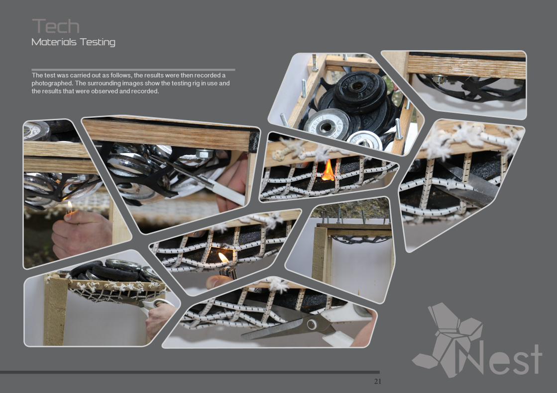
21
Materials Testing
Tech
The test was carried out as follows, the results were then recorded a photographed. The surrounding images show the testing rig in use and the results that were observed and recorded.
22
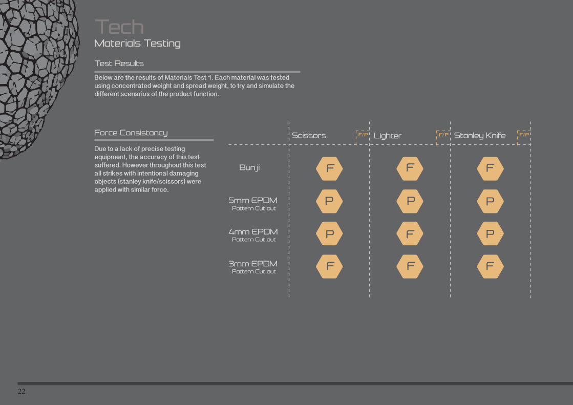
Below are the results of Materials Test 1. Each material was tested using concentrated weight and spread weight, to try and simulate the different scenarios of the product function.
Test Results
Materials Testing
Tech
Bunji
2001 2005 2010
F/P F/P F/P
3mm EPDM
4mm EPDM
5mm EPDMPattern Cut out
Pattern Cut out
Pattern Cut out
Scissors Lighter Stanley Knife
Due to a lack of precise testing equipment, the accuracy of this test suffered. However throughout this test all strikes with intentional damaging objects (stanley knife/scissors) were applied with similar force.
Force Consistancy
F
P P P
F F
P
F F F
F P
23
Relevant standards: Materials should resist intentional damage, materials will be tested to ensure resistance knife and flame damages.The choice of materials should be appropriate where extreme climatic or atmospheric conditions are to be ex- pected.Materials Testing
Tech
Test EvaluationTest Evaluation
Observations
What was learnt......
Once the the materials had been exposed to the elements for the specifed time period (48hours), each material was tested against intentional damage. The time period that the marterials were exposed to the elements for, allowed for a more accurate simulation of real world application. The EPDM rubber suffered no noticable deterioration over the time period, however the bunji cord became dis-coloured and possessed noticeable damage due to the element exposure.
The 4mm and 5mm thick EPDM rubber were resistant to the intentional damage of Stanley Knife and Scissors, however the 3mm EPDM rubber failed to resist both. The 4mm and 3mm EPDM rubber sheets failed to resist lighter damage, however even though the falame caused damage to the rubber, the structural integrigty of the material was no compromised.
The bunji cord performed in a different way, as the pictures form the test depict, when the flame came into contact with the bunji cord, the cord itself set alight. The flame continued to burn unitl the benji eventually failed. The structural integrity was compromised.
The 5mm EPDM Rubber sheet was resistant to any deterioration over the time period where it was exposed to the elements.
The bunji cord failed to resisit the intentional damage test, therfore the use of bunjir/ubber cord would unsuitable for full sclae use.
Overall Mateial Testing Evaluation
Throughought the materials testing process, the 5mm EPDM Rubber (Voronoi Pattern Cut-out) performed in the most suitable way. This material will now be researched further and tested on a 1:1 scale.
24
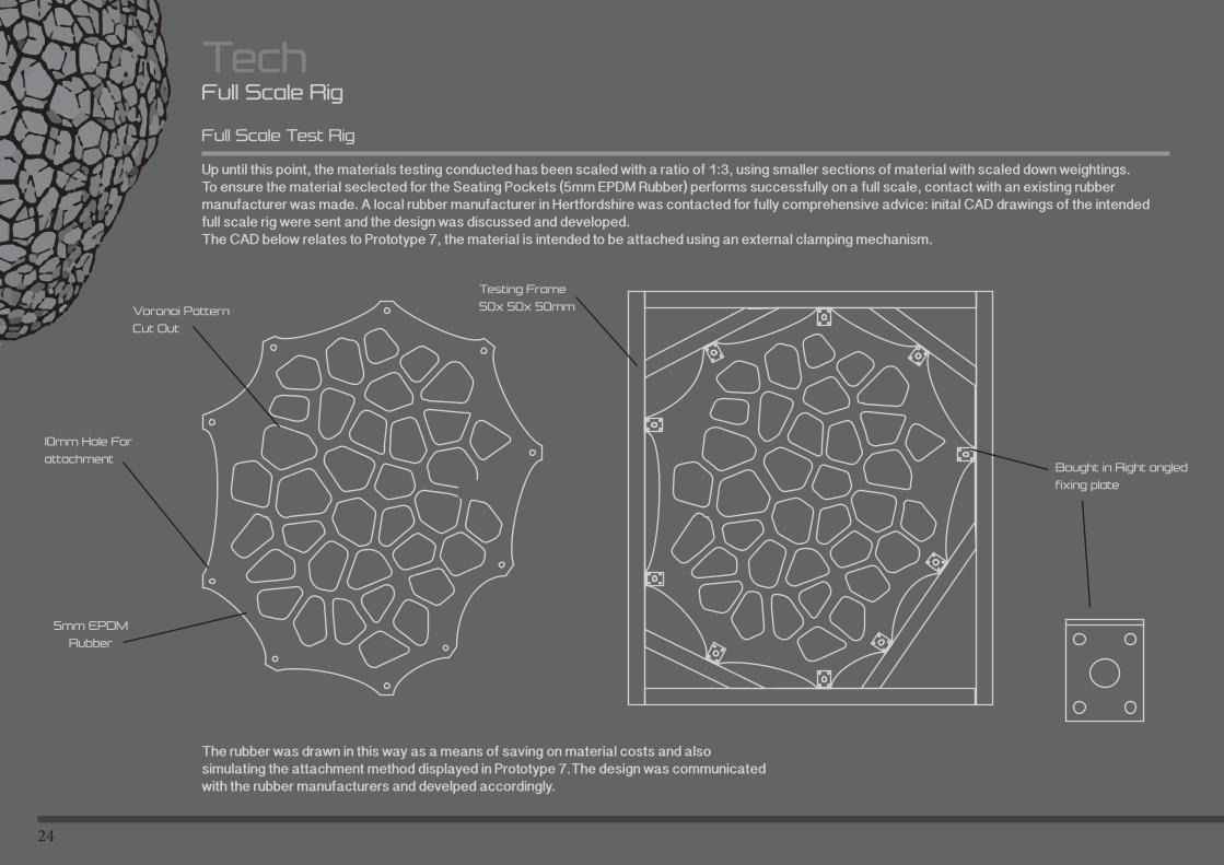
TechFull Scale Rig
Full Scale Test Rig
Up until this point, the materials testing conducted has been scaled with a ratio of 1:3, using smaller sections of material with scaled down weightings. To ensure the material seclected for the Seating Pockets (5mm EPDM Rubber) performs successfully on a full scale, contact with an existing rubber manufacturer was made. A local rubber manufacturer in Hertfordshire was contacted for fully comprehensive advice: inital CAD drawings of the intended full scale rig were sent and the design was discussed and developed. The CAD below relates to Prototype 7, the material is intended to be attached using an external clamping mechanism.
10mm Hole For
attachment
Testing Frame
50x 50x 50mm
5mm EPDM
Rubber
Voronoi Pattern
Cut Out
Bought in Right angled
fixing plate
The rubber was drawn in this way as a means of saving on material costs and also simulating the attachment method displayed in Prototype 7.The design was communicated with the rubber manufacturers and develped accordingly.
25
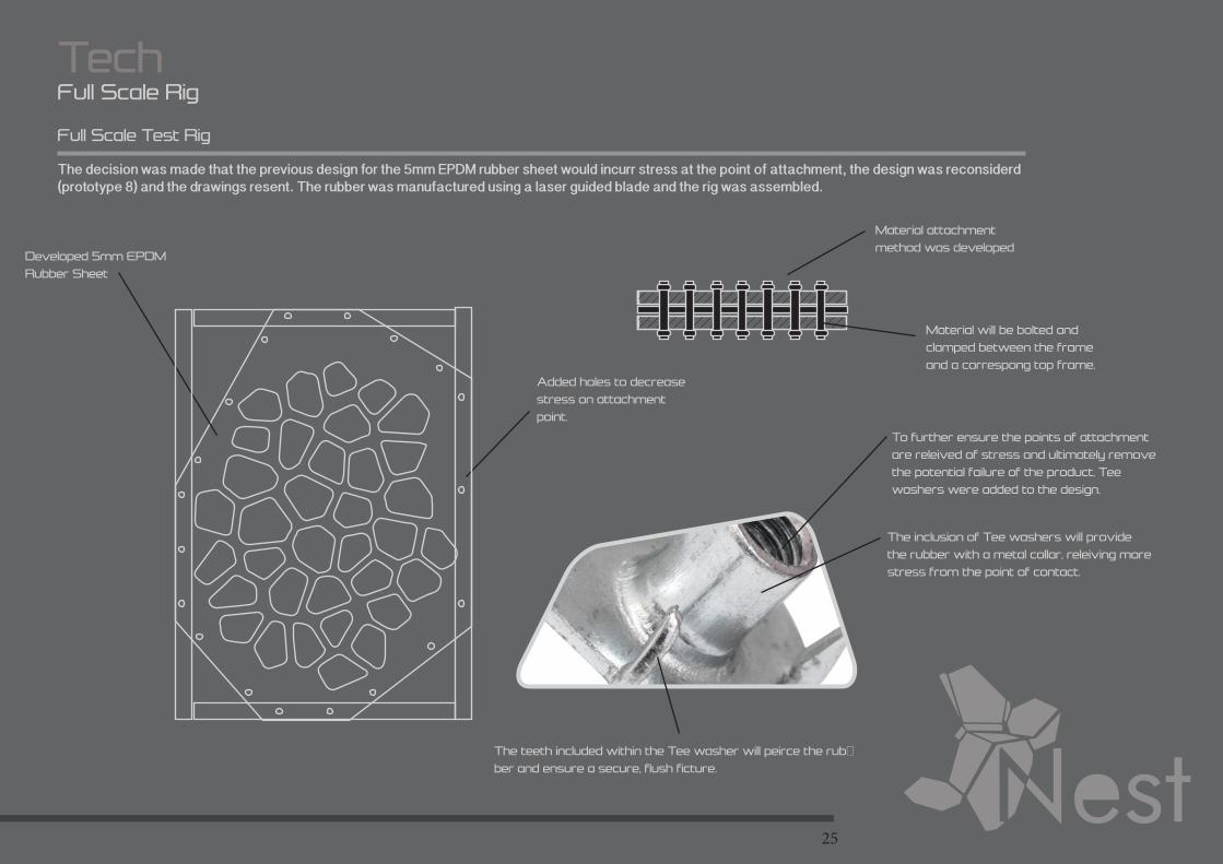
TechFull Scale Rig
Full Scale Test Rig
The decision was made that the previous design for the 5mm EPDM rubber sheet would incurr stress at the point of attachment, the design was reconsiderd (prototype 8) and the drawings resent. The rubber was manufactured using a laser guided blade and the rig was assembled.
Developed 5mm EPDM
Rubber Sheet
Added holes to decrease
stress on attachment
point.
Material attachment
method was developed
Material will be bolted and
clamped between the frame
and a correspong top frame.
To further ensure the points of attachment
are releived of stress and ultimately remove
the potential failure of the product, Tee
washers were added to the design.
The inclusion of Tee washers will provide
the rubber with a metal collar, releiving more
stress from the point of contact.
The teeth included within the Tee washer will peirce the rub-
ber and ensure a secure, flush ficture.
26
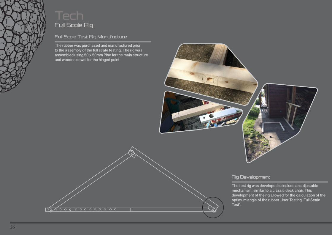
TechFull Scale Rig
Full Scale Test Rig Manufacture
The rubber was purchased and manufactured prior to the assembly of the full scale test rig. The rig was assembled using 50 x 50mm Pine for the main structure and wooden dowel for the hinged point.
Rig Development
The test rig was developed to include an adjustable mechanism, similar to a classic deck chair. This development of the rig allowed for the calculation of the optimum angle of the rubber. User Testing ‘Full Scale Test’.

27
28
TechDesign For Manufacture and Assembly
Introduction
Throughout this section I estimate and evaluate and redesign my product to adhere to existing manufacturing guidelines. The following headings will be addressed, calculated and recalculated: -Estimate the manufacturing costs-Reduce the costs of components -Reduce the cost of assembly -Reduce the costs of supporting production-Consider the impact of DFM decisions on other factors.
Due to the large-scale nature of my design, designing for manufacture was considered throughout the development of form and function (Prototype 4 development). The large-scale nature of the initial prototypes raised uncertainty when manufacturing processes were considered. The previous prototypes were themed around using one moulded structure, however it was apparent that this would result in extortionately large manufacturing costs. The designs were evaluated and re-designed to fit existing manufacturing guidelines.
Throughout this section I will show the evaluation and redesign carried out in order to develop the product for mass manufacture and ultimately reduce the cost of production.
29
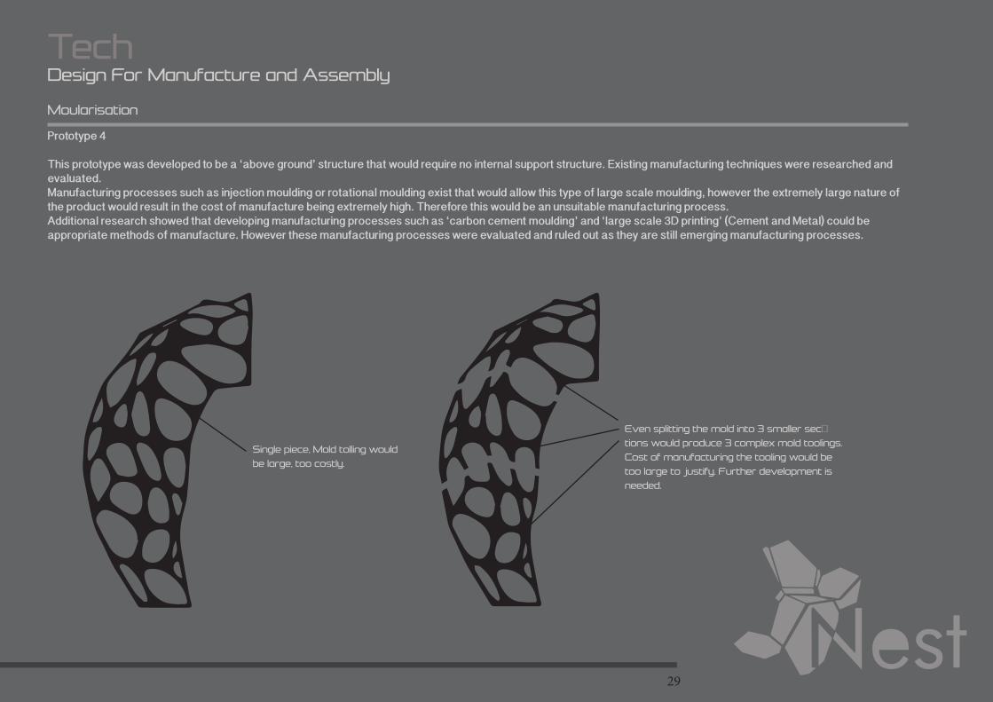
TechDesign For Manufacture and Assembly
Moularisation
Prototype 4
This prototype was developed to be a ‘above ground’ structure that would require no internal support structure. Existing manufacturing techniques were researched and evaluated. Manufacturing processes such as injection moulding or rotational moulding exist that would allow this type of large scale moulding, however the extremely large nature of the product would result in the cost of manufacture being extremely high. Therefore this would be an unsuitable manufacturing process.Additional research showed that developing manufacturing processes such as ‘carbon cement moulding’ and ‘large scale 3D printing’ (Cement and Metal) could be appropriate methods of manufacture. However these manufacturing processes were evaluated and ruled out as they are still emerging manufacturing processes.
Even splitting the mold into 3 smaller sec-
tions would produce 3 complex mold toolings.
Cost of manufacturing the tooling would be
too large to justify. Further development is
needed.
Single piece, Mold tolling would
be large, too costly.
30
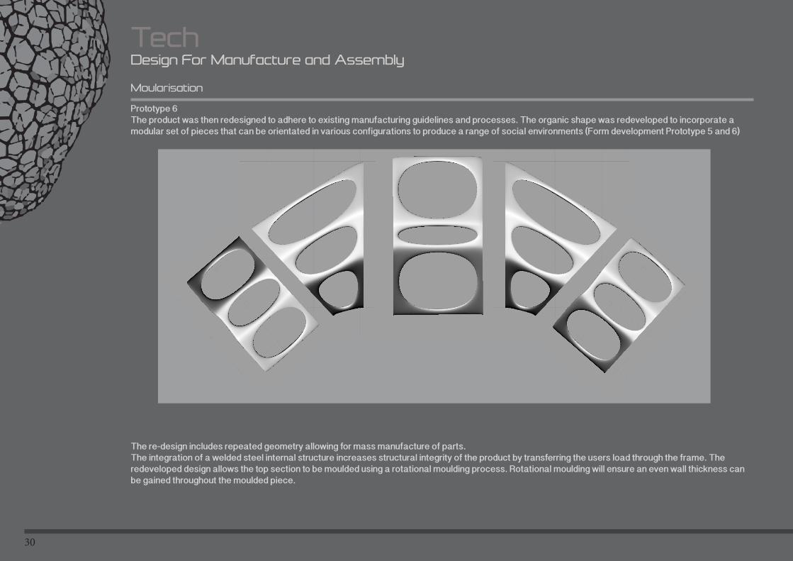
Moularisation
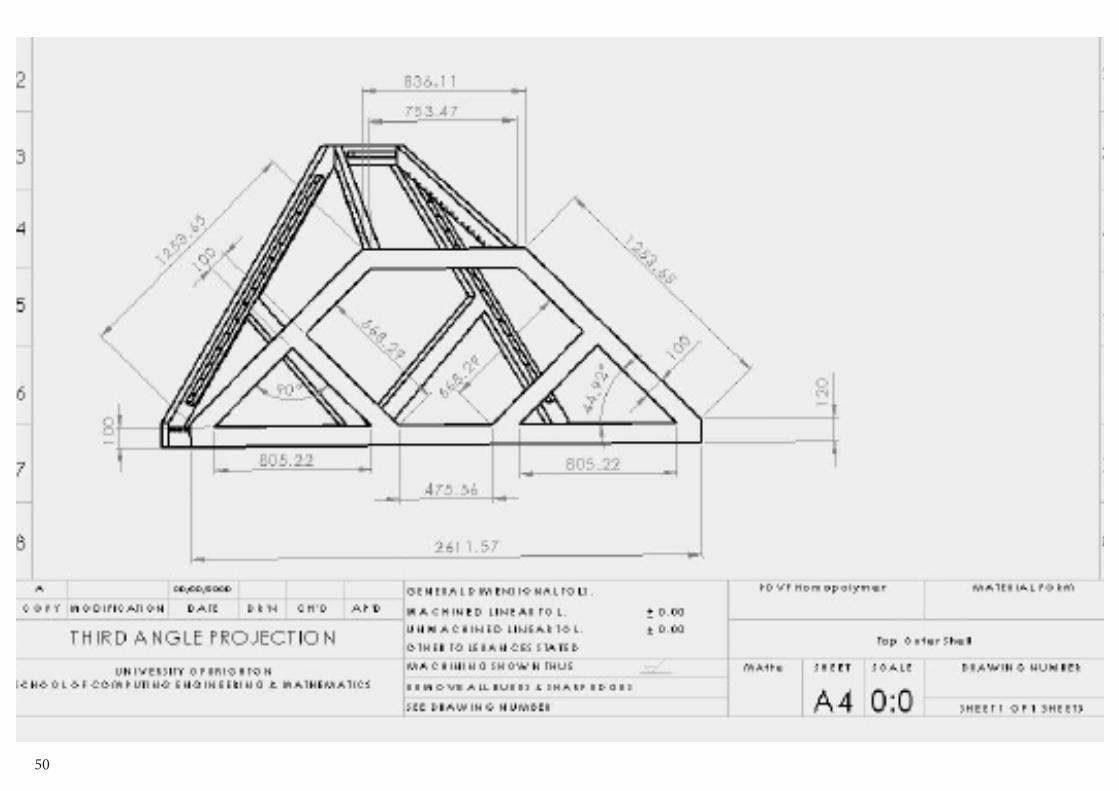
Prototype 6The product was then redesigned to adhere to existing manufacturing guidelines and processes. The organic shape was redeveloped to incorporate a modular set of pieces that can be orientated in various configurations to produce a range of social environments (Form development Prototype 5 and 6)
TechDesign For Manufacture and Assembly
The re-design includes repeated geometry allowing for mass manufacture of parts. The integration of a welded steel internal structure increases structural integrity of the product by transferring the users load through the frame. The redeveloped design allows the top section to be moulded using a rotational moulding process. Rotational moulding will ensure an even wall thickness can be gained throughout the moulded piece.
31
TechDesign For Manufacture and Assembly
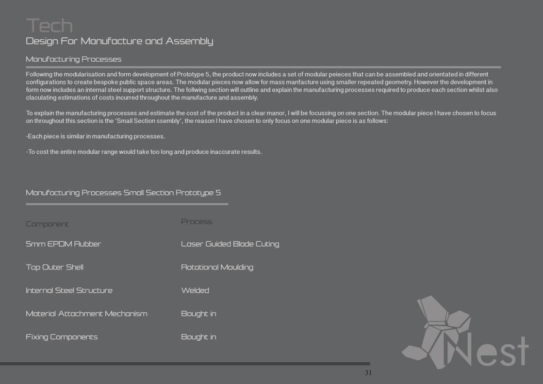
Manufacturing Processes
Following the modularisation and form development of Prototype 5, the product now includes a set of modular peieces that can be assembled and orientated in different configurations to create bespoke public space areas. The modular pieces now allow for mass manfacture using smaller repeated geometry. However the development in form now includes an internal steel support structure. The follwing section will outline and explain the manufacturing processes required to produce each section whilst also claculating estimations of costs incurred throughout the manufacture and assembly.
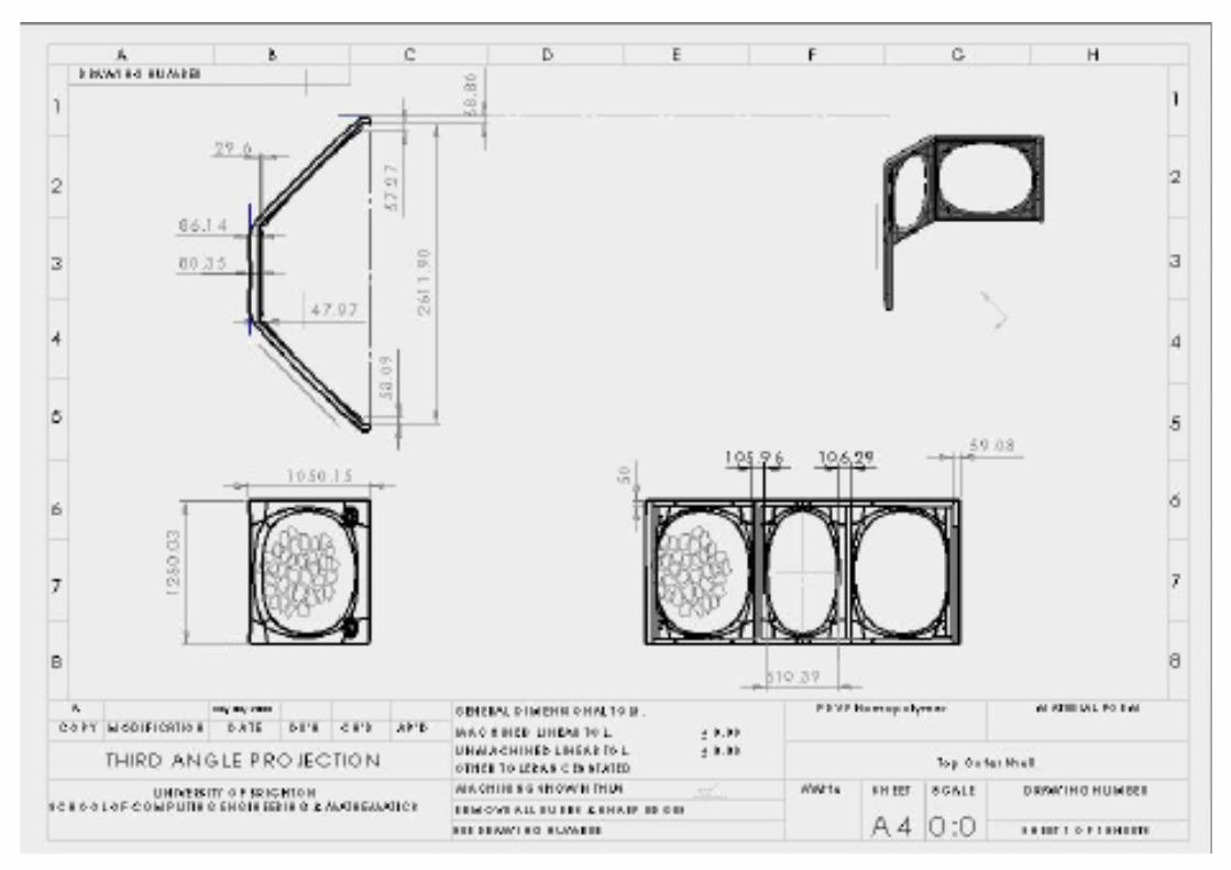
To explain the manufacturing processes and estimate the cost of the product in a clear manor, I will be focussing on one section. The modular piece I have chosen to focus on throughout this section is the ‘Small Section ssembly’, the reason I have chosen to only focus on one modular piece is as follows:
-Each piece is similar in manufacturing processes.
-To cost the entire modular range would take too long and produce inaccurate results.
Manufacturing Processes Small Section Prototype 5
5mm EPDM Rubber
Top Outer Shell
Internal Steel Structure
Material Attachment Mechanism
Fixing Components
Laser Guided Blade Cuting
Rotational Moulding
Welded
Bought in
Bought in
ProcessComponent
32
TechDesign For Manufacture and Assembly
Rotational Molding
As previously mentioned, the Top Shell of each modular section will be rotationally molded. Rotational molding is a process often used to mould large components at a lower cost of production than other injection molding techniques.
What is Rotational Moulding
Rotational molding is one of the fastest growing plastics moulding processes today, the process uses a resin powder instead of pellets. Rotational molding machines are made in a wide range of sizes. They normally consist of molds, an oven, a cooling chamber, and mold spindles. The spindles are mounted on a rotating axis, which provides a uniform coating of the plastic inside each mold.
Molds (or tooling) are either fabricated from welded sheet steel or cast. The fabrication method is often driven by part size and complexity; most intricate parts are likely made out of cast tooling. Molds are typically manufactured from stainless steel or aluminum.
Differences between Rotation Molding and Other Plastic Molding Techniques
The key differences between rotational molding and other plastics molding techniques, such as blow and injection molding, are as follows:
-Resin powder is used instead of pellets;
-The resin melts in the molds instead of being forced under pressure into the molds in a molten state;
-The mold has a biaxial rotation;
-Rotomolding molds are less expensive because of their simplicity;
-Operating pressures are relatively low, allowing molds to be made from less expensive materials.
33
TechDesign For Manufacture and Assembly
Advantages of Rotational Molding
To justify the use of rotational molding as the manufacturing process of the outer shell, I shall identify the advantages of rotational molding and outline the way in which it suits my design. Rotationl molding offers significant advantages when compared with other molding techniques:
-Cost of molds and tooling are relatively lowAll the modular pieces will require even larger moulds, rotational moldin will allow the cost of the tooling
-The rotomolding technique is easily adapted ato short production runsEach modular section will be produced in batches of 100-500, Rotational molding can offer quick, short production runs.
-Hollow, totally enclosed items as well as pieces with openings can be made.The top outer shell will an enclosed hollw mould.
-Rotational molding eliminates the need for secondary tooling.No need for secondary tooling, overall product cost of manufacture is less
-There is little to no wasteWill allow the manufacture of the product to be cost efficient.
-Wall thickness and piece weight can be easily controlled.Accuracy within each molded piece can be obtained.
-Virtually any size pieces can be rotationally molded.The intricate geometry of the modular pieces can be sussessfully molded.
-Rotational molding yeilds pieces with excellent surface detail and finish.The finish of each piece will be of high quality and detail. (speaker inserts)
-Plastic or metal inserts can be moled as integral parts of the item.Metal inserts can be inserted into the mold tool prior to assembly to allow for attachment to the steel structure.
-Double wall constructions are feasible.If needed, additional structural integrity can be added to each mold piece.
34
TechDesign For Manufacture and Assembly
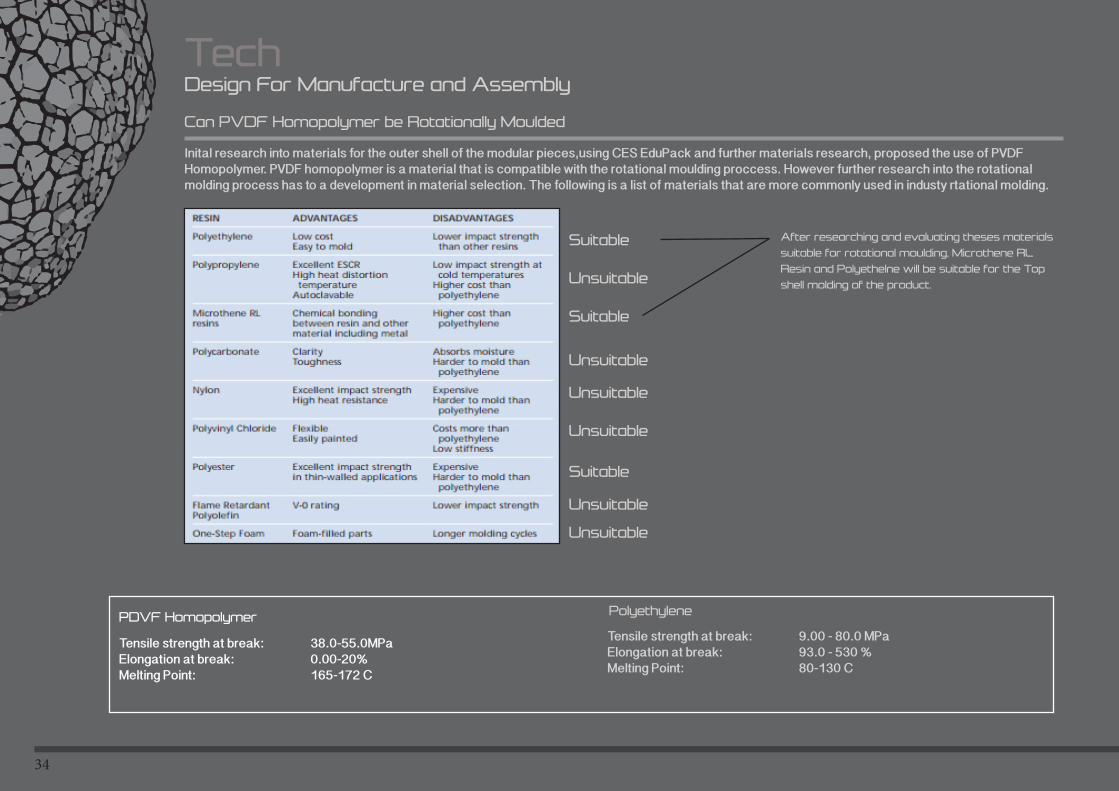
Can PVDF Homopolymer be Rotationally Moulded
Inital research into materials for the outer shell of the modular pieces,using CES EduPack and further materials research, proposed the use of PVDF Homopolymer. PVDF homopolymer is a material that is compatible with the rotational moulding proccess. However further research into the rotational molding process has to a development in material selection. The following is a list of materials that are more commonly used in industy rtational molding.
Suitable
Unsuitable
Suitable
Unsuitable
Unsuitable
Unsuitable
Suitable
Unsuitable
Unsuitable
After researching and evaluating theses materials
suitable for rotational moulding, Microthene RL
Resin and Polyethelne will be suitable for the Top
shell molding of the product.
PDVF Homopolymer
Tensile strength at break: 38.0-55.0MPaElongation at break: 0.00-20%Melting Point: 165-172 C
Polyethylene
Tensile strength at break: 9.00 - 80.0 MPa Elongation at break: 93.0 - 530 % Melting Point: 80-130 C
35
TechDesign For Manufacture and Assembly
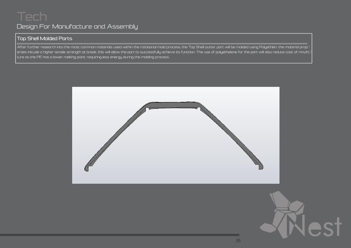
Top Shell Molded Parts
After further research into the most common materials used within the rotational mold process, the Top Shell outter part will be molded using Polyethlen. the material prop-
erties inlcude a higher tensile strength at break, this will allow the part to successfully achieve its function. The use of polyethelene for the part will also reduce cost of mnufc-
ture as the PE has a lower melting point, requiring less energy during the molding process.
36
TechDesign For Assembly
Assembly
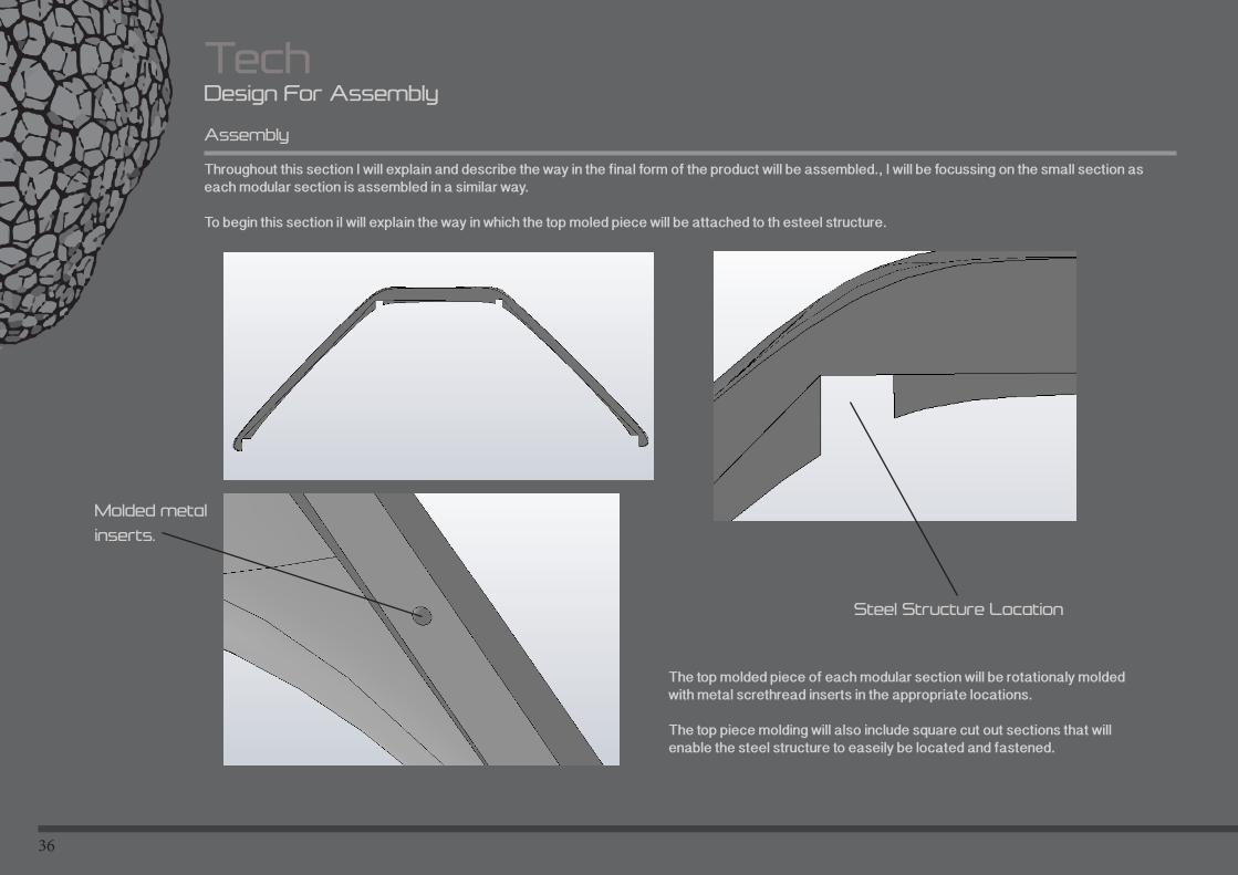
Throughout this section I will explain and describe the way in the final form of the product will be assembled., I will be focussing on the small section as each modular section is assembled in a similar way.
To begin this section iI will explain the way in which the top moled piece will be attached to th esteel structure.
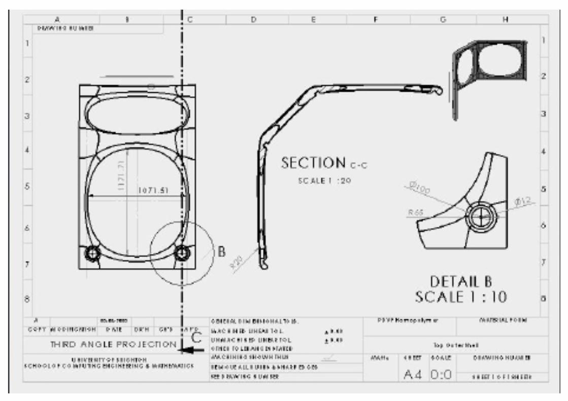
The top molded piece of each modular section will be rotationaly molded with metal screthread inserts in the appropriate locations.
The top piece molding will also include square cut out sections that will enable the steel structure to easeily be located and fastened.
Steel Structure Location
Molded metal
inserts.
37
TechDesign For Assembly
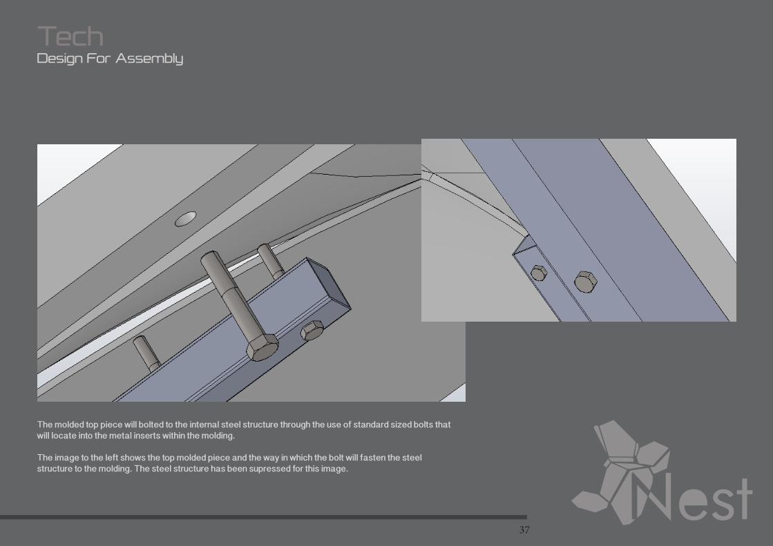
The molded top piece will bolted to the internal steel structure through the use of standard sized bolts that will locate into the metal inserts within the molding.
The image to the left shows the top molded piece and the way in which the bolt will fasten the steel structure to the molding. The steel structure has been supressed for this image.
38
TechDesign For Assembly
Assembly
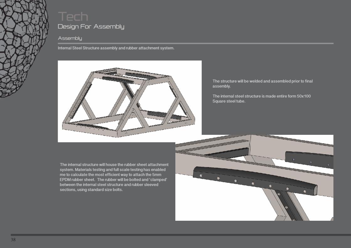
Internal Steel Structure assembly and rubber attachment system.
The structure will be welded and assembled prior to final assembly.
The internal steel structure is made entire form 50x100 Square steel tube.
The internal structure will house the rubber sheet attachment system. Materials testing and full scale testing has enabled me to calculate the most efficient way to attach the 5mm EPDM rubber sheet. The rubber will be bolted and ‘clamped’ between the internal steel structure and rubber sleeved sections, using standard size bolts.
39
TechDesign For Assembly
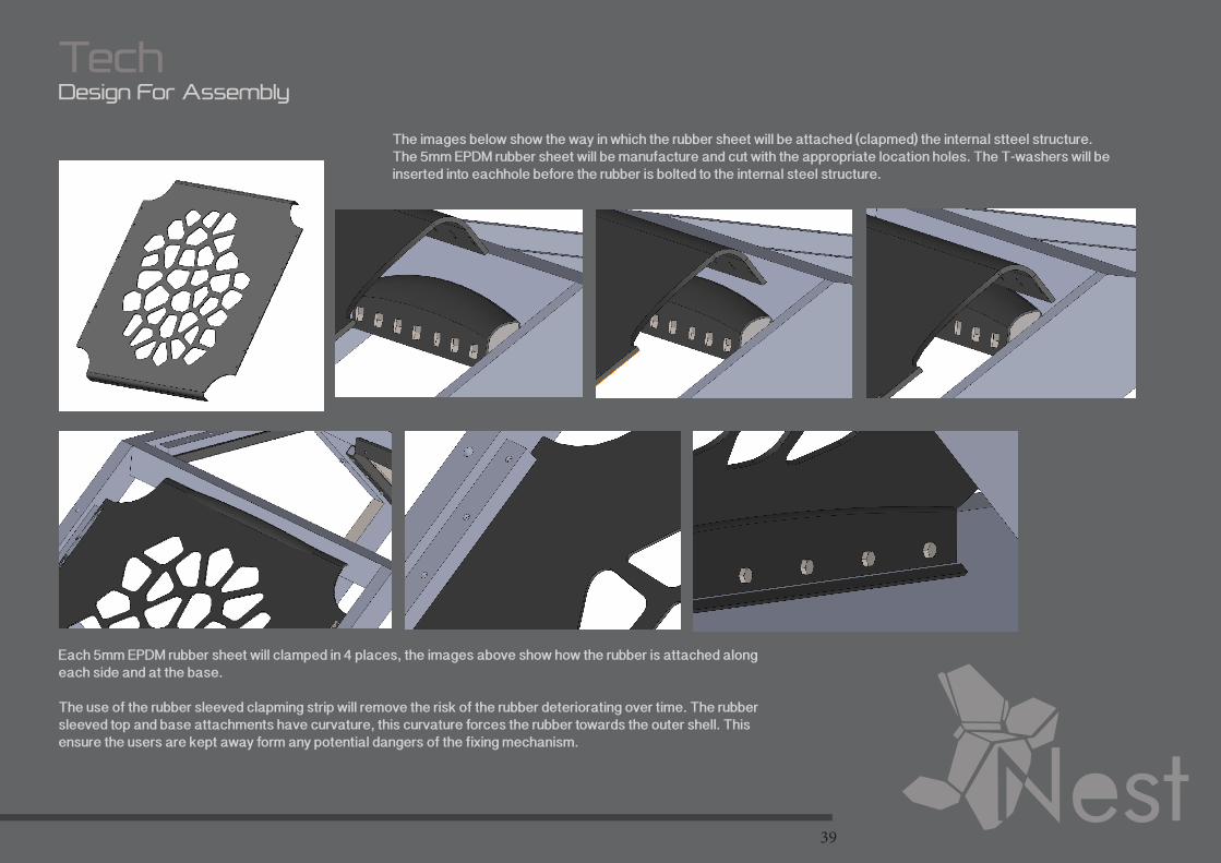
The images below show the way in which the rubber sheet will be attached (clapmed) the internal stteel structure.The 5mm EPDM rubber sheet will be manufacture and cut with the appropriate location holes. The T-washers will be inserted into eachhole before the rubber is bolted to the internal steel structure.
Each 5mm EPDM rubber sheet will clamped in 4 places, the images above show how the rubber is attached along each side and at the base.
The use of the rubber sleeved clapming strip will remove the risk of the rubber deteriorating over time. The rubber sleeved top and base attachments have curvature, this curvature forces the rubber towards the outer shell. This ensure the users are kept away form any potential dangers of the fixing mechanism.
40
TechDesign For Assembly
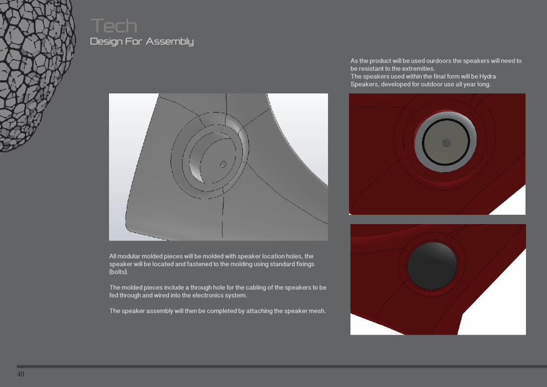
All modular molded pieces will be molded with speaker location holes, the speaker will be located and fastened to the molding using standard fixings (bolts).
The molded pieces include a through hole for the cabling of the speakers to be fed through and wired into the electronics system.
The speaker assembly will then be completed by attaching the speaker mesh.
As the product will be used ourdoors the speakers will need to be resistant to the extremities. The speakers used within the final form will be Hydra Speakers, developed for outdoor use all year long.
41
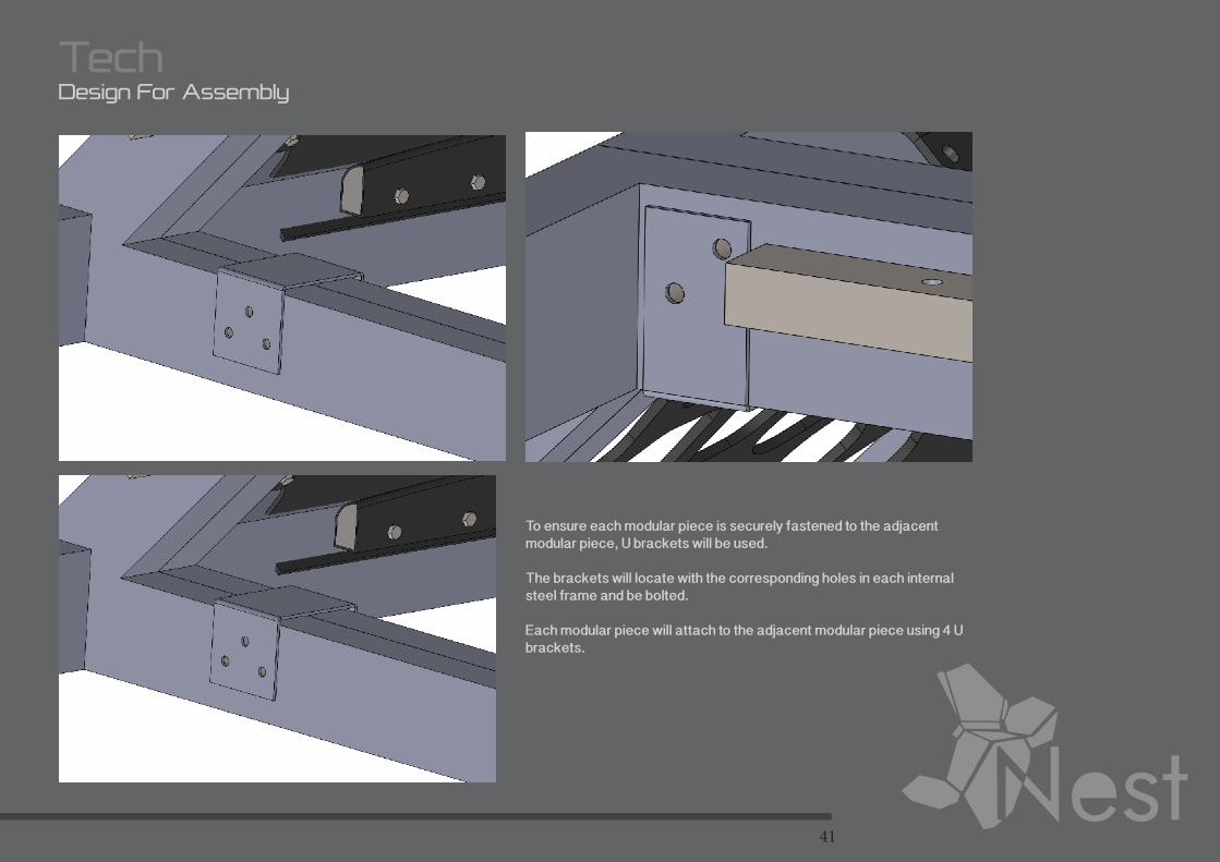
TechDesign For Assembly
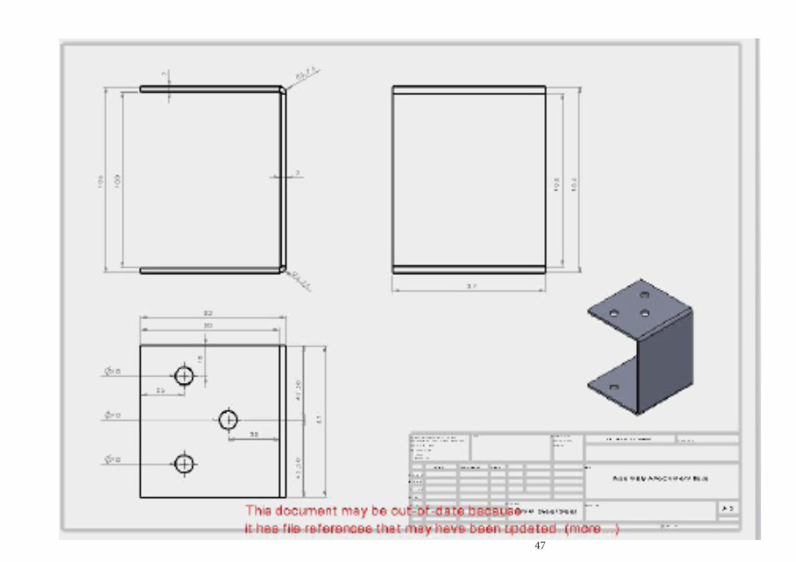
To ensure each modular piece is securely fastened to the adjacent modular piece, U brackets will be used.
The brackets will locate with the corresponding holes in each internal steel frame and be bolted.
Each modular piece will attach to the adjacent modular piece using 4 U brackets.
42
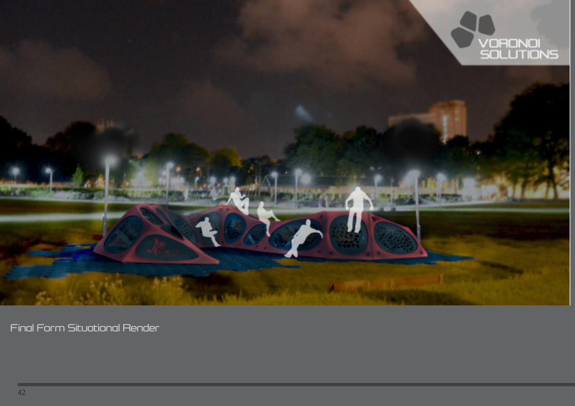
Final Form Situational Render

43
44
TechReferences
TU Delft IO2041-Industriele Productie
Kumagaya
Rotation Moulding
Designing Pleasurable Products
Patrck W. Jordan
Human factors in Product Design
Current Practise and Future Trends
William s. Green and Patrick W. Jordan
Human Fators in Consumer Products
Neville Stanton
PProduct Design and Development
karl T Ulrich Steven D Eppinger

45
46
47
48
49
50
51
52
53

54

55