Embed Size (px)
Citation preview

Net-Net® 9000 EMSConfiguration Guide
Release Version 6.0
Acme Packet, Inc.71 Third AvenueBurlington, MA 01803 USAt 781-328-4400f 781-425-5077www.acmepacket.com
Last Updated: July 16, 2008Document Number: 400-0084-60 Rev. 1.0.0

Notices©2002—2008 Acme Packet, Inc., Burlington, Massachusetts. All rights reserved. Acme Packet®, Session Aware Networking®, Net-Net®, and related marks are registered trademarks of Acme Packet, Inc. All other brand names are trademarks, registered trademarks, or service marks of their respective companies or organizations.
Patents Pending, Acme Packet, Inc.
The Acme Packet Documentation Set and the Net-Net systems described therein are the property of Acme Packet, Inc. This documentation is provided for informational use only, and the information contained within the documentation is subject to change without notice.
Acme Packet, Inc. shall not be liable for any loss of profits, loss of use, loss of data, interruption of business, nor for indirect, special, incidental, consequential, or exemplary damages of any kind, arising in any way in connection with the Acme Packet software or hardware, third party software or hardware, or the documentation. Some jurisdictions do not allow the exclusion or limitation of incidental or consequential damages, so the above exclusions may not apply. These limitations are independent from all other provisions and shall apply notwithstanding the failure of any remedy provided herein.
Copying or reproducing the information contained within this documentation without the express written permission of Acme Packet, Inc., 71 Third Avenue, Burlington, MA 01803, USA is prohibited. No part may be reproduced or retransmitted.
Acme Packet Net-Net products are protected by one or more of the following patents: United States: 7072303, 7028092, 7002973, 7133923, 7031311, 7142532, 7151781. France: 1342348, 1289225, 1280297, 1341345, 1347621. Germany: 1342348, 1289225, 1280297, 1341345, 1347621. United Kingdom: 1342348, 1289225, 1280297, 1341345, 1347621. Other patents are pending.

Contents
About this Guide . . . . . . . . . . . . . . . . . . . . . . . . . . . . . . . . . . . . . . . . . . . . . . . . . 19
Overview . . . . . . . . . . . . . . . . . . . . . . . . . . . . . . . . . . . . . . . . . . . . . . . . . . . . . . . . . . . . . . . . . . . . . . .19
Configuring Different Versions of Net-Net SBCs . . . . . . . . . . . . . . . . . . . . . . . . . . . . . . . . . . . .19
Configuration Timestamp . . . . . . . . . . . . . . . . . . . . . . . . . . . . . . . . . . . . . . . . . . . . . . . . . . . . . . .19
Who is Acme Packet? . . . . . . . . . . . . . . . . . . . . . . . . . . . . . . . . . . . . . . . . . . . . . . . . . . . . . . . . . . .20
Associated Documentation . . . . . . . . . . . . . . . . . . . . . . . . . . . . . . . . . . . . . . . . . . . . . . . . . . . . . . .20
Customer Questions, Comments, or Suggestions. . . . . . . . . . . . . . . . . . . . . . . . . . . . . . . . . . . .21
Contact Us . . . . . . . . . . . . . . . . . . . . . . . . . . . . . . . . . . . . . . . . . . . . . . . . . . . . . . . . . . . . . . . . . . . .21
3 Getting Started . . . . . . . . . . . . . . . . . . . . . . . . . . . . . . . . . . . . . . . . . . . . . . . . . . . 21
Introduction. . . . . . . . . . . . . . . . . . . . . . . . . . . . . . . . . . . . . . . . . . . . . . . . . . . . . . . . . . . . . . . . . . . . .21
Using the Net-Net EMS to Configure the Net-Net SBC . . . . . . . . . . . . . . . . . . . . . . . . . . . . . .21
Configuration Timestamp . . . . . . . . . . . . . . . . . . . . . . . . . . . . . . . . . . . . . . . . . . . . . . . . . . . . . . .21
Filtering Configuration Tables . . . . . . . . . . . . . . . . . . . . . . . . . . . . . . . . . . . . . . . . . . . . . . . . . . . .22
Installation and Start-Up . . . . . . . . . . . . . . . . . . . . . . . . . . . . . . . . . . . . . . . . . . . . . . . . . . . . . . . . .24
Hardware Installation Summary . . . . . . . . . . . . . . . . . . . . . . . . . . . . . . . . . . . . . . . . . . . . . . . . . .24
Connecting to Your Net-Net SBC System . . . . . . . . . . . . . . . . . . . . . . . . . . . . . . . . . . . . . . . . . .24
Local Connections and Time-outs . . . . . . . . . . . . . . . . . . . . . . . . . . . . . . . . . . . . . . . . . . . . .24
Telnet Remote Connections and Time-outs. . . . . . . . . . . . . . . . . . . . . . . . . . . . . . . . . . . . . .25
Connecting Using Telnet through Net-Net EMS . . . . . . . . . . . . . . . . . . . . . . . . . . . . . . . . .26
SSH Remote Connections . . . . . . . . . . . . . . . . . . . . . . . . . . . . . . . . . . . . . . . . . . . . . . . . . . . .27
SSH Through Net-Net EMS . . . . . . . . . . . . . . . . . . . . . . . . . . . . . . . . . . . . . . . . . . . . . . . . . .27
System Boot. . . . . . . . . . . . . . . . . . . . . . . . . . . . . . . . . . . . . . . . . . . . . . . . . . . . . . . . . . . . . . . . . . .29
Net-Net SBC Boot Parameters. . . . . . . . . . . . . . . . . . . . . . . . . . . . . . . . . . . . . . . . . . . . . . . . . . . . .30
Displaying Boot Parameters. . . . . . . . . . . . . . . . . . . . . . . . . . . . . . . . . . . . . . . . . . . . . . . . . . . . . .30
Changing Boot Parameters . . . . . . . . . . . . . . . . . . . . . . . . . . . . . . . . . . . . . . . . . . . . . . . . . . . . . .32
Using the ACLI . . . . . . . . . . . . . . . . . . . . . . . . . . . . . . . . . . . . . . . . . . . . . . . . . . . . . . . . . . . . .32
Interrupting Boot in Progress. . . . . . . . . . . . . . . . . . . . . . . . . . . . . . . . . . . . . . . . . . . . . . . . . .33
Virtual IP Address for Management . . . . . . . . . . . . . . . . . . . . . . . . . . . . . . . . . . . . . . . . . . . .34
Setting Up System Basics . . . . . . . . . . . . . . . . . . . . . . . . . . . . . . . . . . . . . . . . . . . . . . . . . . . . . . . . .35
Version 6.0 Net-Net 9200 EMS Configuration Guide 3

NTP Synchronization . . . . . . . . . . . . . . . . . . . . . . . . . . . . . . . . . . . . . . . . . . . . . . . . . . . . . . . . . . .35
Configuring the Time Zone . . . . . . . . . . . . . . . . . . . . . . . . . . . . . . . . . . . . . . . . . . . . . . . . . . .36
About Your Net-Net SBC Image . . . . . . . . . . . . . . . . . . . . . . . . . . . . . . . . . . . . . . . . . . . . . . . . . . .38
Obtaining a New Image. . . . . . . . . . . . . . . . . . . . . . . . . . . . . . . . . . . . . . . . . . . . . . . . . . . . . . . . .38
Using FTP to Copy an Image on Your Net-Net SBC. . . . . . . . . . . . . . . . . . . . . . . . . . . . . . . . . .38
System Image Filename . . . . . . . . . . . . . . . . . . . . . . . . . . . . . . . . . . . . . . . . . . . . . . . . . . . . . .39
Booting an Image on Your Net-Net SBC . . . . . . . . . . . . . . . . . . . . . . . . . . . . . . . . . . . . . . . . . . . .40
Booting from Flash Memory . . . . . . . . . . . . . . . . . . . . . . . . . . . . . . . . . . . . . . . . . . . . . . . . . . . . .40
Booting from an External Device. . . . . . . . . . . . . . . . . . . . . . . . . . . . . . . . . . . . . . . . . . . . . . . . . .41
Software Licensing. . . . . . . . . . . . . . . . . . . . . . . . . . . . . . . . . . . . . . . . . . . . . . . . . . . . . . . . . . . . . . .42
Unlicensed Net-Net SBCs . . . . . . . . . . . . . . . . . . . . . . . . . . . . . . . . . . . . . . . . . . . . . . . . . . . . . . .43
Obtaining a License . . . . . . . . . . . . . . . . . . . . . . . . . . . . . . . . . . . . . . . . . . . . . . . . . . . . . . . . . . . .43
Trial Licenses . . . . . . . . . . . . . . . . . . . . . . . . . . . . . . . . . . . . . . . . . . . . . . . . . . . . . . . . . . . . . . .43
Adding Licenses . . . . . . . . . . . . . . . . . . . . . . . . . . . . . . . . . . . . . . . . . . . . . . . . . . . . . . . . . . . . . . .43
Deleting Licenses . . . . . . . . . . . . . . . . . . . . . . . . . . . . . . . . . . . . . . . . . . . . . . . . . . . . . . . . . . . . . .44
Expiration. . . . . . . . . . . . . . . . . . . . . . . . . . . . . . . . . . . . . . . . . . . . . . . . . . . . . . . . . . . . . . . . . . . . .45
Viewing Licenses . . . . . . . . . . . . . . . . . . . . . . . . . . . . . . . . . . . . . . . . . . . . . . . . . . . . . . . . . . . . . .45
RADIUS Authentication . . . . . . . . . . . . . . . . . . . . . . . . . . . . . . . . . . . . . . . . . . . . . . . . . . . . . . . . . .46
How It Works . . . . . . . . . . . . . . . . . . . . . . . . . . . . . . . . . . . . . . . . . . . . . . . . . . . . . . . . . . . . . . . . .46
PAP Handshake . . . . . . . . . . . . . . . . . . . . . . . . . . . . . . . . . . . . . . . . . . . . . . . . . . . . . . . . . . . . . . .47
PAP Client Request Example . . . . . . . . . . . . . . . . . . . . . . . . . . . . . . . . . . . . . . . . . . . . . . . . . .47
PAP RADIUS Response . . . . . . . . . . . . . . . . . . . . . . . . . . . . . . . . . . . . . . . . . . . . . . . . . . . . . .48
CHAP Handshake . . . . . . . . . . . . . . . . . . . . . . . . . . . . . . . . . . . . . . . . . . . . . . . . . . . . . . . . . . . . .48
CHAP Client Request Example . . . . . . . . . . . . . . . . . . . . . . . . . . . . . . . . . . . . . . . . . . . . . . . .48
CHAP RADIUS Response . . . . . . . . . . . . . . . . . . . . . . . . . . . . . . . . . . . . . . . . . . . . . . . . . . . .48
MS-CHAP-v2 Handshake . . . . . . . . . . . . . . . . . . . . . . . . . . . . . . . . . . . . . . . . . . . . . . . . . . . . . . .48
MS-CHAP-v2 Client Request Example . . . . . . . . . . . . . . . . . . . . . . . . . . . . . . . . . . . . . . . . .49
MS-CHAP-v2 RADIUS Response. . . . . . . . . . . . . . . . . . . . . . . . . . . . . . . . . . . . . . . . . . . . . .49
Management Protocol Behavior . . . . . . . . . . . . . . . . . . . . . . . . . . . . . . . . . . . . . . . . . . . . . . . . . .49
Configuring RADIUS Authentication . . . . . . . . . . . . . . . . . . . . . . . . . . . . . . . . . . . . . . . . . . . . . .50
RADIUS Server Settings. . . . . . . . . . . . . . . . . . . . . . . . . . . . . . . . . . . . . . . . . . . . . . . . . . . . . .51
4 System Configuration . . . . . . . . . . . . . . . . . . . . . . . . . . . . . . . . . . . . . . . . . . . . . 49
Introduction. . . . . . . . . . . . . . . . . . . . . . . . . . . . . . . . . . . . . . . . . . . . . . . . . . . . . . . . . . . . . . . . . . . . .49
General System Information . . . . . . . . . . . . . . . . . . . . . . . . . . . . . . . . . . . . . . . . . . . . . . . . . . . . . .49
Configuring General System Information . . . . . . . . . . . . . . . . . . . . . . . . . . . . . . . . . . . . . . . . . .49
System Description and Location . . . . . . . . . . . . . . . . . . . . . . . . . . . . . . . . . . . . . . . . . . . . . .50
Physical Interfaces . . . . . . . . . . . . . . . . . . . . . . . . . . . . . . . . . . . . . . . . . . . . . . . . . . . . . . . . . . . . . . .50
Overview . . . . . . . . . . . . . . . . . . . . . . . . . . . . . . . . . . . . . . . . . . . . . . . . . . . . . . . . . . . . . . . . . . . . .50
Types of Physical Interfaces . . . . . . . . . . . . . . . . . . . . . . . . . . . . . . . . . . . . . . . . . . . . . . . . . . . . . .50
4 Net-Net 9200 EMS Configuration Guide Version 6.0
Slot and Card Location. . . . . . . . . . . . . . . . . . . . . . . . . . . . . . . . . . . . . . . . . . . . . . . . . . . . . . . . . .51
Management Interfaces . . . . . . . . . . . . . . . . . . . . . . . . . . . . . . . . . . . . . . . . . . . . . . . . . . . . . .51
Before You Configure . . . . . . . . . . . . . . . . . . . . . . . . . . . . . . . . . . . . . . . . . . . . . . . . . . . . . . . . . . .52
Configuring Physical Interfaces . . . . . . . . . . . . . . . . . . . . . . . . . . . . . . . . . . . . . . . . . . . . . . . . . . .52
Configuring Physical Interfaces . . . . . . . . . . . . . . . . . . . . . . . . . . . . . . . . . . . . . . . . . . . . . . . . . . .52
Configuring the Physical Interface . . . . . . . . . . . . . . . . . . . . . . . . . . . . . . . . . . . . . . . . . . . . .53
Network Interfaces. . . . . . . . . . . . . . . . . . . . . . . . . . . . . . . . . . . . . . . . . . . . . . . . . . . . . . . . . . . . . . .54
Overview . . . . . . . . . . . . . . . . . . . . . . . . . . . . . . . . . . . . . . . . . . . . . . . . . . . . . . . . . . . . . . . . . . . . .54
IP Configuration . . . . . . . . . . . . . . . . . . . . . . . . . . . . . . . . . . . . . . . . . . . . . . . . . . . . . . . . . . . . . . .54
VLANs . . . . . . . . . . . . . . . . . . . . . . . . . . . . . . . . . . . . . . . . . . . . . . . . . . . . . . . . . . . . . . . . . . . .54
VLAN Network Layer Segmentation . . . . . . . . . . . . . . . . . . . . . . . . . . . . . . . . . . . . . . . . . . .55
Overlapping Networks . . . . . . . . . . . . . . . . . . . . . . . . . . . . . . . . . . . . . . . . . . . . . . . . . . . . . . .55
HIP . . . . . . . . . . . . . . . . . . . . . . . . . . . . . . . . . . . . . . . . . . . . . . . . . . . . . . . . . . . . . . . . . . . . . . .55
Configuring Network Interfaces . . . . . . . . . . . . . . . . . . . . . . . . . . . . . . . . . . . . . . . . . . . . . . . . . .55
Special Considerations . . . . . . . . . . . . . . . . . . . . . . . . . . . . . . . . . . . . . . . . . . . . . . . . . . . . . . .55
Configuring the Network Interface . . . . . . . . . . . . . . . . . . . . . . . . . . . . . . . . . . . . . . . . . . . . .56
Configuring a HIP Interface . . . . . . . . . . . . . . . . . . . . . . . . . . . . . . . . . . . . . . . . . . . . . . . . . . .57
Enabling Management Traffic . . . . . . . . . . . . . . . . . . . . . . . . . . . . . . . . . . . . . . . . . . . . . . . . .58
SNMP . . . . . . . . . . . . . . . . . . . . . . . . . . . . . . . . . . . . . . . . . . . . . . . . . . . . . . . . . . . . . . . . . . . . . . . . . .58
Overview . . . . . . . . . . . . . . . . . . . . . . . . . . . . . . . . . . . . . . . . . . . . . . . . . . . . . . . . . . . . . . . . . . . . .58
Basic SNMP Parameters . . . . . . . . . . . . . . . . . . . . . . . . . . . . . . . . . . . . . . . . . . . . . . . . . . . . . .58
SNMP Community . . . . . . . . . . . . . . . . . . . . . . . . . . . . . . . . . . . . . . . . . . . . . . . . . . . . . . . . . .59
Trap Receivers . . . . . . . . . . . . . . . . . . . . . . . . . . . . . . . . . . . . . . . . . . . . . . . . . . . . . . . . . . . . . .59
Configuring SNMP . . . . . . . . . . . . . . . . . . . . . . . . . . . . . . . . . . . . . . . . . . . . . . . . . . . . . . . . . . . . . .59
SNMP Configuration Overview . . . . . . . . . . . . . . . . . . . . . . . . . . . . . . . . . . . . . . . . . . . . . . . . . .59
SNMP Configuration . . . . . . . . . . . . . . . . . . . . . . . . . . . . . . . . . . . . . . . . . . . . . . . . . . . . . . . . . . .59
SNMP Community Configuration. . . . . . . . . . . . . . . . . . . . . . . . . . . . . . . . . . . . . . . . . . . . . .61
Alarm Thresholds. . . . . . . . . . . . . . . . . . . . . . . . . . . . . . . . . . . . . . . . . . . . . . . . . . . . . . . . . . . . . . . .64
Configuring Alarm Thresholds . . . . . . . . . . . . . . . . . . . . . . . . . . . . . . . . . . . . . . . . . . . . . . . . . . .64
HDR Trap for Data Push Success . . . . . . . . . . . . . . . . . . . . . . . . . . . . . . . . . . . . . . . . . . . . . . . . . .65
Configuring HDR Data Push Success Trap . . . . . . . . . . . . . . . . . . . . . . . . . . . . . . . . . . . . . . . . .65
Persistent Protocol Tracing. . . . . . . . . . . . . . . . . . . . . . . . . . . . . . . . . . . . . . . . . . . . . . . . . . . . . . . .66
About Persistent Protocol Tracing. . . . . . . . . . . . . . . . . . . . . . . . . . . . . . . . . . . . . . . . . . . . . . . . .66
About the Logs . . . . . . . . . . . . . . . . . . . . . . . . . . . . . . . . . . . . . . . . . . . . . . . . . . . . . . . . . . . . . . . .66
Process Logs . . . . . . . . . . . . . . . . . . . . . . . . . . . . . . . . . . . . . . . . . . . . . . . . . . . . . . . . . . . . . . .66
Communication Logs . . . . . . . . . . . . . . . . . . . . . . . . . . . . . . . . . . . . . . . . . . . . . . . . . . . . . . . .67
Protocol Trace Logs. . . . . . . . . . . . . . . . . . . . . . . . . . . . . . . . . . . . . . . . . . . . . . . . . . . . . . . . . .67
Configuring Persistent Protocol Tracing. . . . . . . . . . . . . . . . . . . . . . . . . . . . . . . . . . . . . . . . . . . .67
Syslog and Process Logs . . . . . . . . . . . . . . . . . . . . . . . . . . . . . . . . . . . . . . . . . . . . . . . . . . . . . . . . . .69
Overview of Log Files. . . . . . . . . . . . . . . . . . . . . . . . . . . . . . . . . . . . . . . . . . . . . . . . . . . . . . . . . . .69
Version 6.0 Net-Net 9200 EMS Configuration Guide 5

Process Log Messages . . . . . . . . . . . . . . . . . . . . . . . . . . . . . . . . . . . . . . . . . . . . . . . . . . . . . . .69
Syslog . . . . . . . . . . . . . . . . . . . . . . . . . . . . . . . . . . . . . . . . . . . . . . . . . . . . . . . . . . . . . . . . . . . . .69
. . . . . . . . . . . . . . . . . . . . . . . . . . . . . . . . . . . . . . . . . . . . . . . . . . . . . . . . . . . . . . . . . . . . . . . . . .70
Global Log Level . . . . . . . . . . . . . . . . . . . . . . . . . . . . . . . . . . . . . . . . . . . . . . . . . . . . . . . . . . . .71
Configuring a Process Log Server . . . . . . . . . . . . . . . . . . . . . . . . . . . . . . . . . . . . . . . . . . . . . .71
Task-Specific Logging . . . . . . . . . . . . . . . . . . . . . . . . . . . . . . . . . . . . . . . . . . . . . . . . . . . . . . .71
Facility Logging for Specific Tasks. . . . . . . . . . . . . . . . . . . . . . . . . . . . . . . . . . . . . . . . . . . . . .72
General Management Support . . . . . . . . . . . . . . . . . . . . . . . . . . . . . . . . . . . . . . . . . . . . . . . .73
Host Routes . . . . . . . . . . . . . . . . . . . . . . . . . . . . . . . . . . . . . . . . . . . . . . . . . . . . . . . . . . . . . . . . . . . . .74
Overview . . . . . . . . . . . . . . . . . . . . . . . . . . . . . . . . . . . . . . . . . . . . . . . . . . . . . . . . . . . . . . . . . . . . .74
Configuring Host Routes . . . . . . . . . . . . . . . . . . . . . . . . . . . . . . . . . . . . . . . . . . . . . . . . . . . . . . . .74
Accounting. . . . . . . . . . . . . . . . . . . . . . . . . . . . . . . . . . . . . . . . . . . . . . . . . . . . . . . . . . . . . . . . . . . . . .75
SIP Session Accounting . . . . . . . . . . . . . . . . . . . . . . . . . . . . . . . . . . . . . . . . . . . . . . . . . . . . . . . . .75
Accounting Configuration . . . . . . . . . . . . . . . . . . . . . . . . . . . . . . . . . . . . . . . . . . . . . . . . . . . . . . .76
Accounting Server. . . . . . . . . . . . . . . . . . . . . . . . . . . . . . . . . . . . . . . . . . . . . . . . . . . . . . . . . . .78
Packet Trace. . . . . . . . . . . . . . . . . . . . . . . . . . . . . . . . . . . . . . . . . . . . . . . . . . . . . . . . . . . . . . . . . . . . .81
How It Works . . . . . . . . . . . . . . . . . . . . . . . . . . . . . . . . . . . . . . . . . . . . . . . . . . . . . . . . . . . . . . . . .81
Packet Trace Scenarios . . . . . . . . . . . . . . . . . . . . . . . . . . . . . . . . . . . . . . . . . . . . . . . . . . . . . . . . . .82
Packet Trace for One Endpoint . . . . . . . . . . . . . . . . . . . . . . . . . . . . . . . . . . . . . . . . . . . . . . . .82
Packet Trace for Both Call Legs . . . . . . . . . . . . . . . . . . . . . . . . . . . . . . . . . . . . . . . . . . . . . . . .83
Packet Trace for a Net-Net SBC Signaling Address . . . . . . . . . . . . . . . . . . . . . . . . . . . . . . .83
Configuring Packet Tracing . . . . . . . . . . . . . . . . . . . . . . . . . . . . . . . . . . . . . . . . . . . . . . . . . . . . . . .84
System ACLs . . . . . . . . . . . . . . . . . . . . . . . . . . . . . . . . . . . . . . . . . . . . . . . . . . . . . . . . . . . . . . . . . . . .86
Configuring System ACLs . . . . . . . . . . . . . . . . . . . . . . . . . . . . . . . . . . . . . . . . . . . . . . . . . . . . . . .86
Adding an ACL for the Management Interface . . . . . . . . . . . . . . . . . . . . . . . . . . . . . . . . . . .86
5 Realms and Nested Realms . . . . . . . . . . . . . . . . . . . . . . . . . . . . . . . . . . . . . . . . 77
Introduction. . . . . . . . . . . . . . . . . . . . . . . . . . . . . . . . . . . . . . . . . . . . . . . . . . . . . . . . . . . . . . . . . . . . .77
Overview . . . . . . . . . . . . . . . . . . . . . . . . . . . . . . . . . . . . . . . . . . . . . . . . . . . . . . . . . . . . . . . . . . . . .77
About Realms and Network Interfaces . . . . . . . . . . . . . . . . . . . . . . . . . . . . . . . . . . . . . . . . . .78
About the SIP Home Realm. . . . . . . . . . . . . . . . . . . . . . . . . . . . . . . . . . . . . . . . . . . . . . . . . . .78
About Realms and Other Net-Net SBC Functions . . . . . . . . . . . . . . . . . . . . . . . . . . . . . . . .78
Configuration Overview . . . . . . . . . . . . . . . . . . . . . . . . . . . . . . . . . . . . . . . . . . . . . . . . . . . . . . . . . .79
Before You Configure . . . . . . . . . . . . . . . . . . . . . . . . . . . . . . . . . . . . . . . . . . . . . . . . . . . . . . . . . . .79
Configuration Overview. . . . . . . . . . . . . . . . . . . . . . . . . . . . . . . . . . . . . . . . . . . . . . . . . . . . . . . . .79
Configuration Timestamp . . . . . . . . . . . . . . . . . . . . . . . . . . . . . . . . . . . . . . . . . . . . . . . . . . . . . . .81
Configuring Realms. . . . . . . . . . . . . . . . . . . . . . . . . . . . . . . . . . . . . . . . . . . . . . . . . . . . . . . . . . . . . .81
Creating the Realm. . . . . . . . . . . . . . . . . . . . . . . . . . . . . . . . . . . . . . . . . . . . . . . . . . . . . . . . . . . . .81
Configuring the Realm . . . . . . . . . . . . . . . . . . . . . . . . . . . . . . . . . . . . . . . . . . . . . . . . . . . . . . . . . .83
6 Net-Net 9200 EMS Configuration Guide Version 6.0

Nested Realms . . . . . . . . . . . . . . . . . . . . . . . . . . . . . . . . . . . . . . . . . . . . . . . . . . . . . . . . . . . . . . . . . .84
Configuring Nested Realms. . . . . . . . . . . . . . . . . . . . . . . . . . . . . . . . . . . . . . . . . . . . . . . . . . . . . .86
Configuring Nested Realms. . . . . . . . . . . . . . . . . . . . . . . . . . . . . . . . . . . . . . . . . . . . . . . . . . . . . .86
Choosing the Parent Realm . . . . . . . . . . . . . . . . . . . . . . . . . . . . . . . . . . . . . . . . . . . . . . . . . . .87
Realm-Based Packet Marking . . . . . . . . . . . . . . . . . . . . . . . . . . . . . . . . . . . . . . . . . . . . . . . . . . . . .87
About TOS/DiffServ . . . . . . . . . . . . . . . . . . . . . . . . . . . . . . . . . . . . . . . . . . . . . . . . . . . . . . . . . . . .87
ToS Byte . . . . . . . . . . . . . . . . . . . . . . . . . . . . . . . . . . . . . . . . . . . . . . . . . . . . . . . . . . . . . . . . . . .88
DiffServ Byte . . . . . . . . . . . . . . . . . . . . . . . . . . . . . . . . . . . . . . . . . . . . . . . . . . . . . . . . . . . . . . .88
Packet Marking for Media . . . . . . . . . . . . . . . . . . . . . . . . . . . . . . . . . . . . . . . . . . . . . . . . . . . . . . .88
Configuring Packet Marking by Media Type . . . . . . . . . . . . . . . . . . . . . . . . . . . . . . . . . . . . . . . .88
Creating the QoS Marking Profile. . . . . . . . . . . . . . . . . . . . . . . . . . . . . . . . . . . . . . . . . . . . . .89
Applying the QoS Marking Profile . . . . . . . . . . . . . . . . . . . . . . . . . . . . . . . . . . . . . . . . . . . . .90
Configuring Packet Marking for Signaling . . . . . . . . . . . . . . . . . . . . . . . . . . . . . . . . . . . . . . . . . .90
Creating a Class Policy . . . . . . . . . . . . . . . . . . . . . . . . . . . . . . . . . . . . . . . . . . . . . . . . . . . . . . .91
Applying a Class Policy to a Realm . . . . . . . . . . . . . . . . . . . . . . . . . . . . . . . . . . . . . . . . . . . . .92
Steering Pools . . . . . . . . . . . . . . . . . . . . . . . . . . . . . . . . . . . . . . . . . . . . . . . . . . . . . . . . . . . . . . . . . . .92
Configuration Overview. . . . . . . . . . . . . . . . . . . . . . . . . . . . . . . . . . . . . . . . . . . . . . . . . . . . . . . . .93
Configuring Steering Pools . . . . . . . . . . . . . . . . . . . . . . . . . . . . . . . . . . . . . . . . . . . . . . . . . . . . . .93
Multiple Interface Realms . . . . . . . . . . . . . . . . . . . . . . . . . . . . . . . . . . . . . . . . . . . . . . . . . . . . . . . .94
How It Works . . . . . . . . . . . . . . . . . . . . . . . . . . . . . . . . . . . . . . . . . . . . . . . . . . . . . . . . . . . . . . . . .95
Steering Pool Port Allocation . . . . . . . . . . . . . . . . . . . . . . . . . . . . . . . . . . . . . . . . . . . . . . . . . . . .97
Configuring Multiple Interface Realms. . . . . . . . . . . . . . . . . . . . . . . . . . . . . . . . . . . . . . . . . . . . .97
Media over TCP . . . . . . . . . . . . . . . . . . . . . . . . . . . . . . . . . . . . . . . . . . . . . . . . . . . . . . . . . . . . . . . . .99
TCP Bearer Conditions. . . . . . . . . . . . . . . . . . . . . . . . . . . . . . . . . . . . . . . . . . . . . . . . . . . . . . . . . .99
TCP Port Selection . . . . . . . . . . . . . . . . . . . . . . . . . . . . . . . . . . . . . . . . . . . . . . . . . . . . . . . . . . . . .99
SDP Offer Example . . . . . . . . . . . . . . . . . . . . . . . . . . . . . . . . . . . . . . . . . . . . . . . . . . . . . . . . .102
Timers. . . . . . . . . . . . . . . . . . . . . . . . . . . . . . . . . . . . . . . . . . . . . . . . . . . . . . . . . . . . . . . . . . . .103
Configuring Media Over TCP . . . . . . . . . . . . . . . . . . . . . . . . . . . . . . . . . . . . . . . . . . . . . . . . . . .103
Media Management Behind the Same IP . . . . . . . . . . . . . . . . . . . . . . . . . . . . . . . . . . . . . . . . . .104
Additional Media Management Options . . . . . . . . . . . . . . . . . . . . . . . . . . . . . . . . . . . . . . . . . .104
Configuring Media Management Behind the Same IP . . . . . . . . . . . . . . . . . . . . . . . . . . . . . . .104
6 SIP Signaling Services. . . . . . . . . . . . . . . . . . . . . . . . . . . . . . . . . . . . . . . . . . . . 105
Introduction. . . . . . . . . . . . . . . . . . . . . . . . . . . . . . . . . . . . . . . . . . . . . . . . . . . . . . . . . . . . . . . . . . . .105
About the Net-Net SBC and SIP . . . . . . . . . . . . . . . . . . . . . . . . . . . . . . . . . . . . . . . . . . . . . . . . . .105
Types of SIP Devices. . . . . . . . . . . . . . . . . . . . . . . . . . . . . . . . . . . . . . . . . . . . . . . . . . . . . . . . . . .105
Basic Service Models. . . . . . . . . . . . . . . . . . . . . . . . . . . . . . . . . . . . . . . . . . . . . . . . . . . . . . . . . . .106
About B2BUA . . . . . . . . . . . . . . . . . . . . . . . . . . . . . . . . . . . . . . . . . . . . . . . . . . . . . . . . . . . . .106
SIP B2BUA Peering. . . . . . . . . . . . . . . . . . . . . . . . . . . . . . . . . . . . . . . . . . . . . . . . . . . . . . . . .106
B2BUA Hosted IP Services . . . . . . . . . . . . . . . . . . . . . . . . . . . . . . . . . . . . . . . . . . . . . . . . . . .107
Version 6.0 Net-Net 9200 EMS Configuration Guide 7

SIP B2BUA and L3/L5 NAT . . . . . . . . . . . . . . . . . . . . . . . . . . . . . . . . . . . . . . . . . . . . . . . . . .107
About SIP Interfaces . . . . . . . . . . . . . . . . . . . . . . . . . . . . . . . . . . . . . . . . . . . . . . . . . . . . . . . . . . .107
SIP Network Models and Types . . . . . . . . . . . . . . . . . . . . . . . . . . . . . . . . . . . . . . . . . . . . . . . . . .107
Network Model . . . . . . . . . . . . . . . . . . . . . . . . . . . . . . . . . . . . . . . . . . . . . . . . . . . . . . . . . . . . . . .108
Network Type . . . . . . . . . . . . . . . . . . . . . . . . . . . . . . . . . . . . . . . . . . . . . . . . . . . . . . . . . . . . . . . .108
Default Network Model and Type. . . . . . . . . . . . . . . . . . . . . . . . . . . . . . . . . . . . . . . . . . . . . . . .108
Upgrade Considerations . . . . . . . . . . . . . . . . . . . . . . . . . . . . . . . . . . . . . . . . . . . . . . . . . . . . . . .108
Configuring the Network Type and Network Model . . . . . . . . . . . . . . . . . . . . . . . . . . . . . . . .108
Configuring the Network Model . . . . . . . . . . . . . . . . . . . . . . . . . . . . . . . . . . . . . . . . . . . . . .109
Configuring the Network Type . . . . . . . . . . . . . . . . . . . . . . . . . . . . . . . . . . . . . . . . . . . . . . .109
Configuring the Net-Net SBC for SIP Signaling . . . . . . . . . . . . . . . . . . . . . . . . . . . . . . . . . . . .110
Using the Net-Net EMS to Configure the Net-Net SBC . . . . . . . . . . . . . . . . . . . . . . . . . . . . .111
Configuration Timestamp . . . . . . . . . . . . . . . . . . . . . . . . . . . . . . . . . . . . . . . . . . . . . . . . . . . . . .111
Configuring the Home Realm . . . . . . . . . . . . . . . . . . . . . . . . . . . . . . . . . . . . . . . . . . . . . . . . . . . .111
Overview . . . . . . . . . . . . . . . . . . . . . . . . . . . . . . . . . . . . . . . . . . . . . . . . . . . . . . . . . . . . . . . . . . . .111
SIP NAT Function . . . . . . . . . . . . . . . . . . . . . . . . . . . . . . . . . . . . . . . . . . . . . . . . . . . . . . . . . .112
Home Realm’s Purpose . . . . . . . . . . . . . . . . . . . . . . . . . . . . . . . . . . . . . . . . . . . . . . . . . . . . .112
Configuring the Home Realm . . . . . . . . . . . . . . . . . . . . . . . . . . . . . . . . . . . . . . . . . . . . . . . . . . .112
Configuring a SIP Interface . . . . . . . . . . . . . . . . . . . . . . . . . . . . . . . . . . . . . . . . . . . . . . . . . . . . . .114
Overview . . . . . . . . . . . . . . . . . . . . . . . . . . . . . . . . . . . . . . . . . . . . . . . . . . . . . . . . . . . . . . . . . . . .114
About SIP Ports. . . . . . . . . . . . . . . . . . . . . . . . . . . . . . . . . . . . . . . . . . . . . . . . . . . . . . . . . . . . . . .114
Preferred SIP Port . . . . . . . . . . . . . . . . . . . . . . . . . . . . . . . . . . . . . . . . . . . . . . . . . . . . . . . . . .114
Proxy Mode . . . . . . . . . . . . . . . . . . . . . . . . . . . . . . . . . . . . . . . . . . . . . . . . . . . . . . . . . . . . . . . . . .114
Redirect Action . . . . . . . . . . . . . . . . . . . . . . . . . . . . . . . . . . . . . . . . . . . . . . . . . . . . . . . . . . . . . . .115
Trust Mode . . . . . . . . . . . . . . . . . . . . . . . . . . . . . . . . . . . . . . . . . . . . . . . . . . . . . . . . . . . . . . . . . .115
About the Process . . . . . . . . . . . . . . . . . . . . . . . . . . . . . . . . . . . . . . . . . . . . . . . . . . . . . . . . . .115
Configuring a SIP interface . . . . . . . . . . . . . . . . . . . . . . . . . . . . . . . . . . . . . . . . . . . . . . . . . . . . .116
Configuring SIP Ports . . . . . . . . . . . . . . . . . . . . . . . . . . . . . . . . . . . . . . . . . . . . . . . . . . . . . . .122
Configuring Carriers . . . . . . . . . . . . . . . . . . . . . . . . . . . . . . . . . . . . . . . . . . . . . . . . . . . . . . . .123
Configuring SIP Timers . . . . . . . . . . . . . . . . . . . . . . . . . . . . . . . . . . . . . . . . . . . . . . . . . . . . . . . . .124
Overview . . . . . . . . . . . . . . . . . . . . . . . . . . . . . . . . . . . . . . . . . . . . . . . . . . . . . . . . . . . . . . . . . . . .124
Configuring SIP Timers . . . . . . . . . . . . . . . . . . . . . . . . . . . . . . . . . . . . . . . . . . . . . . . . . . . . . . . .124
Configuring SIP Options Tag Handling . . . . . . . . . . . . . . . . . . . . . . . . . . . . . . . . . . . . . . . . . . .126
Overview . . . . . . . . . . . . . . . . . . . . . . . . . . . . . . . . . . . . . . . . . . . . . . . . . . . . . . . . . . . . . . . . . . . .126
Configuration Overview. . . . . . . . . . . . . . . . . . . . . . . . . . . . . . . . . . . . . . . . . . . . . . . . . . . . . . . .126
Configuring SIP Options Tag Handling . . . . . . . . . . . . . . . . . . . . . . . . . . . . . . . . . . . . . . . . . . .127
ENUM: Large UDP Datagram Support for DNS NAPTR Responses . . . . . . . . . . . . . . . . . .129
How It Works . . . . . . . . . . . . . . . . . . . . . . . . . . . . . . . . . . . . . . . . . . . . . . . . . . . . . . . . . . . . . . . .129
Configuring Large UDP Datagram Support. . . . . . . . . . . . . . . . . . . . . . . . . . . . . . . . . . . . . . . .129
Configuring SIP Options . . . . . . . . . . . . . . . . . . . . . . . . . . . . . . . . . . . . . . . . . . . . . . . . . . . . . . . .130
8 Net-Net 9200 EMS Configuration Guide Version 6.0

Overview . . . . . . . . . . . . . . . . . . . . . . . . . . . . . . . . . . . . . . . . . . . . . . . . . . . . . . . . . . . . . . . . . . . .130
Global SIP Options. . . . . . . . . . . . . . . . . . . . . . . . . . . . . . . . . . . . . . . . . . . . . . . . . . . . . . . . . . . .130
SIP Interface Options . . . . . . . . . . . . . . . . . . . . . . . . . . . . . . . . . . . . . . . . . . . . . . . . . . . . . . . . . .135
SIP Session Agent Options . . . . . . . . . . . . . . . . . . . . . . . . . . . . . . . . . . . . . . . . . . . . . . . . . . . . .136
SIP Realm Options . . . . . . . . . . . . . . . . . . . . . . . . . . . . . . . . . . . . . . . . . . . . . . . . . . . . . . . . . . . .136
Configuring SIP Options . . . . . . . . . . . . . . . . . . . . . . . . . . . . . . . . . . . . . . . . . . . . . . . . . . . . . . .136
Accessing Global Options . . . . . . . . . . . . . . . . . . . . . . . . . . . . . . . . . . . . . . . . . . . . . . . . . . .136
Selecting Options . . . . . . . . . . . . . . . . . . . . . . . . . . . . . . . . . . . . . . . . . . . . . . . . . . . . . . . . . .137
SIP Security . . . . . . . . . . . . . . . . . . . . . . . . . . . . . . . . . . . . . . . . . . . . . . . . . . . . . . . . . . . . . . . . . . . .138
Denial of Service Protection. . . . . . . . . . . . . . . . . . . . . . . . . . . . . . . . . . . . . . . . . . . . . . . . . . . . .138
Levels of DoS protection . . . . . . . . . . . . . . . . . . . . . . . . . . . . . . . . . . . . . . . . . . . . . . . . . . . .139
Configuration Overview. . . . . . . . . . . . . . . . . . . . . . . . . . . . . . . . . . . . . . . . . . . . . . . . . . . . . . . .139
Configuring Security. . . . . . . . . . . . . . . . . . . . . . . . . . . . . . . . . . . . . . . . . . . . . . . . . . . . . . . . . . .140
SIP Delayed Media Update . . . . . . . . . . . . . . . . . . . . . . . . . . . . . . . . . . . . . . . . . . . . . . . . . . . . . .140
How it Works . . . . . . . . . . . . . . . . . . . . . . . . . . . . . . . . . . . . . . . . . . . . . . . . . . . . . . . . . . . . . . . .140
Configuring SIP Delayed Media Update . . . . . . . . . . . . . . . . . . . . . . . . . . . . . . . . . . . . . . . . . .140
Configuring the SIP NAT Function . . . . . . . . . . . . . . . . . . . . . . . . . . . . . . . . . . . . . . . . . . . . . . .141
Overview . . . . . . . . . . . . . . . . . . . . . . . . . . . . . . . . . . . . . . . . . . . . . . . . . . . . . . . . . . . . . . . . . . . .141
NAT Modes . . . . . . . . . . . . . . . . . . . . . . . . . . . . . . . . . . . . . . . . . . . . . . . . . . . . . . . . . . . . . . .142
Adding a maddr Parameter to a URI. . . . . . . . . . . . . . . . . . . . . . . . . . . . . . . . . . . . . . . . . . .142
About Headers . . . . . . . . . . . . . . . . . . . . . . . . . . . . . . . . . . . . . . . . . . . . . . . . . . . . . . . . . . . . . . .144
Replacing Headers . . . . . . . . . . . . . . . . . . . . . . . . . . . . . . . . . . . . . . . . . . . . . . . . . . . . . . . . .144
Mapping FQDNs. . . . . . . . . . . . . . . . . . . . . . . . . . . . . . . . . . . . . . . . . . . . . . . . . . . . . . . . . . .144
SIP NAT Function Cookies . . . . . . . . . . . . . . . . . . . . . . . . . . . . . . . . . . . . . . . . . . . . . . . . . . . . .145
userinfo . . . . . . . . . . . . . . . . . . . . . . . . . . . . . . . . . . . . . . . . . . . . . . . . . . . . . . . . . . . . . . . . . .145
host. . . . . . . . . . . . . . . . . . . . . . . . . . . . . . . . . . . . . . . . . . . . . . . . . . . . . . . . . . . . . . . . . . . . . .145
URL Parameter . . . . . . . . . . . . . . . . . . . . . . . . . . . . . . . . . . . . . . . . . . . . . . . . . . . . . . . . . . . .146
tel URL . . . . . . . . . . . . . . . . . . . . . . . . . . . . . . . . . . . . . . . . . . . . . . . . . . . . . . . . . . . . . . . . . . .146
Configuration Overview. . . . . . . . . . . . . . . . . . . . . . . . . . . . . . . . . . . . . . . . . . . . . . . . . . . . . . . .147
SIP NAT Interface . . . . . . . . . . . . . . . . . . . . . . . . . . . . . . . . . . . . . . . . . . . . . . . . . . . . . . . . . .147
SIP NAT Function Policies . . . . . . . . . . . . . . . . . . . . . . . . . . . . . . . . . . . . . . . . . . . . . . . . . . .148
Configuring SIP NAT Function . . . . . . . . . . . . . . . . . . . . . . . . . . . . . . . . . . . . . . . . . . . . . . . . . .149
SIP NAT Interface . . . . . . . . . . . . . . . . . . . . . . . . . . . . . . . . . . . . . . . . . . . . . . . . . . . . . . . . . .149
SIP NAT Policies . . . . . . . . . . . . . . . . . . . . . . . . . . . . . . . . . . . . . . . . . . . . . . . . . . . . . . . . . . .151
Configuring SIP Realm Bridging. . . . . . . . . . . . . . . . . . . . . . . . . . . . . . . . . . . . . . . . . . . . . . . . . .153
About SIP NAT Bridging . . . . . . . . . . . . . . . . . . . . . . . . . . . . . . . . . . . . . . . . . . . . . . . . . . . . . . .153
SIP NAT Bridge Configuration Scenarios. . . . . . . . . . . . . . . . . . . . . . . . . . . . . . . . . . . . . . . . . .154
Many to One Configuration. . . . . . . . . . . . . . . . . . . . . . . . . . . . . . . . . . . . . . . . . . . . . . . . . .155
One-to-One Configuration . . . . . . . . . . . . . . . . . . . . . . . . . . . . . . . . . . . . . . . . . . . . . . . . . .155
SIP NAT Bridge Configuration . . . . . . . . . . . . . . . . . . . . . . . . . . . . . . . . . . . . . . . . . . . . . . . . . .155
Creating a Virtual Home Network . . . . . . . . . . . . . . . . . . . . . . . . . . . . . . . . . . . . . . . . . . . .156
Version 6.0 Net-Net 9200 EMS Configuration Guide 9

Many-to-One Configuration . . . . . . . . . . . . . . . . . . . . . . . . . . . . . . . . . . . . . . . . . . . . . . . . .156
One-to-One Configuration . . . . . . . . . . . . . . . . . . . . . . . . . . . . . . . . . . . . . . . . . . . . . . . . . .157
Shared Session Agent. . . . . . . . . . . . . . . . . . . . . . . . . . . . . . . . . . . . . . . . . . . . . . . . . . . . . . . . . .157
Configuring SIP Hosted NAT Traversal . . . . . . . . . . . . . . . . . . . . . . . . . . . . . . . . . . . . . . . . . . .158
About SIP HNT. . . . . . . . . . . . . . . . . . . . . . . . . . . . . . . . . . . . . . . . . . . . . . . . . . . . . . . . . . . . . . .158
Using HNT with Existing NAT Device . . . . . . . . . . . . . . . . . . . . . . . . . . . . . . . . . . . . . . . . .158
Registering Endpoints. . . . . . . . . . . . . . . . . . . . . . . . . . . . . . . . . . . . . . . . . . . . . . . . . . . . . . .159
Establishing Media Flows. . . . . . . . . . . . . . . . . . . . . . . . . . . . . . . . . . . . . . . . . . . . . . . . . . . .159
Prerequisites . . . . . . . . . . . . . . . . . . . . . . . . . . . . . . . . . . . . . . . . . . . . . . . . . . . . . . . . . . . . . .159
Keeping the NAT Binding Open . . . . . . . . . . . . . . . . . . . . . . . . . . . . . . . . . . . . . . . . . . . . . .159
Working with Multiple Domains. . . . . . . . . . . . . . . . . . . . . . . . . . . . . . . . . . . . . . . . . . . . . . . . .162
HNT Configuration Overview . . . . . . . . . . . . . . . . . . . . . . . . . . . . . . . . . . . . . . . . . . . . . . . . . . .163
SIP HNT Single Domain Example. . . . . . . . . . . . . . . . . . . . . . . . . . . . . . . . . . . . . . . . . . . . .163
SIP HNT Multiple Domain Example. . . . . . . . . . . . . . . . . . . . . . . . . . . . . . . . . . . . . . . . . . .163
Configuring SIP Hosted NAT Traversal . . . . . . . . . . . . . . . . . . . . . . . . . . . . . . . . . . . . . . . . . . .164
NAT Traversal . . . . . . . . . . . . . . . . . . . . . . . . . . . . . . . . . . . . . . . . . . . . . . . . . . . . . . . . . . . . .164
Registration Handling . . . . . . . . . . . . . . . . . . . . . . . . . . . . . . . . . . . . . . . . . . . . . . . . . . . . .165Configuring the Registrar . . . . . . . . . . . . . . . . . . . . . . . . . . . . . . . . . . . . . . . . . . . . . . . . . . . .167
Configuring SIP Server Redundancy . . . . . . . . . . . . . . . . . . . . . . . . . . . . . . . . . . . . . . . . . . . . . .168
Overview . . . . . . . . . . . . . . . . . . . . . . . . . . . . . . . . . . . . . . . . . . . . . . . . . . . . . . . . . . . . . . . . . . . .168
Configuration Overview. . . . . . . . . . . . . . . . . . . . . . . . . . . . . . . . . . . . . . . . . . . . . . . . . . . . . . . .169
Configuring SIP Server Redundancy . . . . . . . . . . . . . . . . . . . . . . . . . . . . . . . . . . . . . . . . . . . . .170
Distributed Media Release . . . . . . . . . . . . . . . . . . . . . . . . . . . . . . . . . . . . . . . . . . . . . . . . . . . . . . .171
Overview . . . . . . . . . . . . . . . . . . . . . . . . . . . . . . . . . . . . . . . . . . . . . . . . . . . . . . . . . . . . . . . . . . . .171
Endpoint Locations. . . . . . . . . . . . . . . . . . . . . . . . . . . . . . . . . . . . . . . . . . . . . . . . . . . . . . . . .171
Location of the Encoded Information . . . . . . . . . . . . . . . . . . . . . . . . . . . . . . . . . . . . . . . . . .171
Example: Distributed Media Release. . . . . . . . . . . . . . . . . . . . . . . . . . . . . . . . . . . . . . . . . . .172
Overview of SIP DMR Configuration . . . . . . . . . . . . . . . . . . . . . . . . . . . . . . . . . . . . . . . . . . . . .173
Configuring Distributed Media Release . . . . . . . . . . . . . . . . . . . . . . . . . . . . . . . . . . . . . . . . . . .173
Configuring the Realm Configuration . . . . . . . . . . . . . . . . . . . . . . . . . . . . . . . . . . . . . . . . . . . .175
Embedded Header (E911) Support . . . . . . . . . . . . . . . . . . . . . . . . . . . . . . . . . . . . . . . . . . . . . . . .175
Configuring Embedded Header Support . . . . . . . . . . . . . . . . . . . . . . . . . . . . . . . . . . . . . . . . . .176
Header and Parameter Manipulation . . . . . . . . . . . . . . . . . . . . . . . . . . . . . . . . . . . . . . . . . . . . .177
Header Manipulation Rules . . . . . . . . . . . . . . . . . . . . . . . . . . . . . . . . . . . . . . . . . . . . . . . . . . . . .177
Header Element Rules . . . . . . . . . . . . . . . . . . . . . . . . . . . . . . . . . . . . . . . . . . . . . . . . . . . . . . . . .177
About SIP Header and Parameter Manipulation. . . . . . . . . . . . . . . . . . . . . . . . . . . . . . . . . . . .177
Role in Trunk Group URI Feature . . . . . . . . . . . . . . . . . . . . . . . . . . . . . . . . . . . . . . . . . . . . .177
Configuring Header and Parameter Manipulation . . . . . . . . . . . . . . . . . . . . . . . . . . . . . . . . . .178
Creating SIP Header Manipulation Rule Sets . . . . . . . . . . . . . . . . . . . . . . . . . . . . . . . . . . .178
Adding Header Rules . . . . . . . . . . . . . . . . . . . . . . . . . . . . . . . . . . . . . . . . . . . . . . . . . . . . . . .179
Adding Methods . . . . . . . . . . . . . . . . . . . . . . . . . . . . . . . . . . . . . . . . . . . . . . . . . . . . . . . . . . .180
10 Net-Net 9200 EMS Configuration Guide Version 6.0

Creating Element Rules . . . . . . . . . . . . . . . . . . . . . . . . . . . . . . . . . . . . . . . . . . . . . . . . . . . . .181
Configuring a Session Agent . . . . . . . . . . . . . . . . . . . . . . . . . . . . . . . . . . . . . . . . . . . . . . . . .184
Configuring a SIP Interface . . . . . . . . . . . . . . . . . . . . . . . . . . . . . . . . . . . . . . . . . . . . . . . . . .184
SIP HMR (Header Manipulation Rules) . . . . . . . . . . . . . . . . . . . . . . . . . . . . . . . . . . . . . . . . . . .185
How It Works . . . . . . . . . . . . . . . . . . . . . . . . . . . . . . . . . . . . . . . . . . . . . . . . . . . . . . . . . . . . . . . .185
Guidelines for Header and Element Rules . . . . . . . . . . . . . . . . . . . . . . . . . . . . . . . . . . . . . .186
Precedence. . . . . . . . . . . . . . . . . . . . . . . . . . . . . . . . . . . . . . . . . . . . . . . . . . . . . . . . . . . . . . . .186
Duplicate Header Names . . . . . . . . . . . . . . . . . . . . . . . . . . . . . . . . . . . . . . . . . . . . . . . . . . . .186
Best Practices. . . . . . . . . . . . . . . . . . . . . . . . . . . . . . . . . . . . . . . . . . . . . . . . . . . . . . . . . . . . . . . . .187
About Regular Expressions . . . . . . . . . . . . . . . . . . . . . . . . . . . . . . . . . . . . . . . . . . . . . . . . . . . . .187
Configuring SIP HMR . . . . . . . . . . . . . . . . . . . . . . . . . . . . . . . . . . . . . . . . . . . . . . . . . . . . . . . . .189
Configuring SIP Header Manipulation Element Rules . . . . . . . . . . . . . . . . . . . . . . . . . . . . . . .191
Setting the Response Code Block . . . . . . . . . . . . . . . . . . . . . . . . . . . . . . . . . . . . . . . . . . . . .193
Applying Multiple SIP Header Manipulation Rulesets . . . . . . . . . . . . . . . . . . . . . . . . . . . . . .195
Configuring Multiple SIP HMR Sets. . . . . . . . . . . . . . . . . . . . . . . . . . . . . . . . . . . . . . . . . . . . . .195
Dialog Transparency . . . . . . . . . . . . . . . . . . . . . . . . . . . . . . . . . . . . . . . . . . . . . . . . . . . . . . . . . . . .196
Overview . . . . . . . . . . . . . . . . . . . . . . . . . . . . . . . . . . . . . . . . . . . . . . . . . . . . . . . . . . . . . . . . . . . .196
Configuring Dialog Transparency . . . . . . . . . . . . . . . . . . . . . . . . . . . . . . . . . . . . . . . . . . . . . . . .196
Route Header Removal . . . . . . . . . . . . . . . . . . . . . . . . . . . . . . . . . . . . . . . . . . . . . . . . . . . . . . . . . .197
Configuring Route Header Removal. . . . . . . . . . . . . . . . . . . . . . . . . . . . . . . . . . . . . . . . . . . . . .197
Via Transparency . . . . . . . . . . . . . . . . . . . . . . . . . . . . . . . . . . . . . . . . . . . . . . . . . . . . . . . . . . . . . . .199
How it Works . . . . . . . . . . . . . . . . . . . . . . . . . . . . . . . . . . . . . . . . . . . . . . . . . . . . . . . . . . . . . . . .199
Configuring Via Transparency . . . . . . . . . . . . . . . . . . . . . . . . . . . . . . . . . . . . . . . . . . . . . . . . . . .199
Symmetric Latching. . . . . . . . . . . . . . . . . . . . . . . . . . . . . . . . . . . . . . . . . . . . . . . . . . . . . . . . . . . . .201
Configuring Symmetric Latching . . . . . . . . . . . . . . . . . . . . . . . . . . . . . . . . . . . . . . . . . . . . . . . .201
Configuring RTCP Symmetric Latching . . . . . . . . . . . . . . . . . . . . . . . . . . . . . . . . . . . . . . . . . . .201
Number Normalization. . . . . . . . . . . . . . . . . . . . . . . . . . . . . . . . . . . . . . . . . . . . . . . . . . . . . . . . . .202
How it Works . . . . . . . . . . . . . . . . . . . . . . . . . . . . . . . . . . . . . . . . . . . . . . . . . . . . . . . . . . . . . . . .202
Terminology. . . . . . . . . . . . . . . . . . . . . . . . . . . . . . . . . . . . . . . . . . . . . . . . . . . . . . . . . . . . . . .202
Calls from IP Endpoints . . . . . . . . . . . . . . . . . . . . . . . . . . . . . . . . . . . . . . . . . . . . . . . . . . . . .202
Calls from IP Peer Network . . . . . . . . . . . . . . . . . . . . . . . . . . . . . . . . . . . . . . . . . . . . . . . . . .203
Configuring Number Normalization . . . . . . . . . . . . . . . . . . . . . . . . . . . . . . . . . . . . . . . . . . . . .203
Realm . . . . . . . . . . . . . . . . . . . . . . . . . . . . . . . . . . . . . . . . . . . . . . . . . . . . . . . . . . . . . . . . . . . .203
Configuring Number Normalization for a Session Agent. . . . . . . . . . . . . . . . . . . . . . . . . .204
Port Mapping . . . . . . . . . . . . . . . . . . . . . . . . . . . . . . . . . . . . . . . . . . . . . . . . . . . . . . . . . . . . . . . . . .206
About SIP Port Mapping . . . . . . . . . . . . . . . . . . . . . . . . . . . . . . . . . . . . . . . . . . . . . . . . . . . . . . .206
How SIP Port Mapping Works . . . . . . . . . . . . . . . . . . . . . . . . . . . . . . . . . . . . . . . . . . . . . . . . . .207
About NAT Table ACL Entries . . . . . . . . . . . . . . . . . . . . . . . . . . . . . . . . . . . . . . . . . . . . . . . . . .207
Using SIP Port Mapping. . . . . . . . . . . . . . . . . . . . . . . . . . . . . . . . . . . . . . . . . . . . . . . . . . . . .208
Dynamic Configuration . . . . . . . . . . . . . . . . . . . . . . . . . . . . . . . . . . . . . . . . . . . . . . . . . . . . .208
Version 6.0 Net-Net 9200 EMS Configuration Guide 11
Registration Statistics . . . . . . . . . . . . . . . . . . . . . . . . . . . . . . . . . . . . . . . . . . . . . . . . . . . . . . .209
Configuring SIP Port Mapping . . . . . . . . . . . . . . . . . . . . . . . . . . . . . . . . . . . . . . . . . . . . . . . . . .209
Configurable Route Recursion . . . . . . . . . . . . . . . . . . . . . . . . . . . . . . . . . . . . . . . . . . . . . . . . . . .210
Example 1 . . . . . . . . . . . . . . . . . . . . . . . . . . . . . . . . . . . . . . . . . . . . . . . . . . . . . . . . . . . . . . . . . . .211
Example 2 . . . . . . . . . . . . . . . . . . . . . . . . . . . . . . . . . . . . . . . . . . . . . . . . . . . . . . . . . . . . . . . . . . .212
Configuring Route Recursion . . . . . . . . . . . . . . . . . . . . . . . . . . . . . . . . . . . . . . . . . . . . . . . . . . .212
Configuring a SIP Interface for SIP Route Recursion . . . . . . . . . . . . . . . . . . . . . . . . . . . . .213
Event Package Interoperability . . . . . . . . . . . . . . . . . . . . . . . . . . . . . . . . . . . . . . . . . . . . . . . . . . .214
Configuring Event Package Interoperability . . . . . . . . . . . . . . . . . . . . . . . . . . . . . . . . . . . . . . .215
REGISTER Forwarding After Call-ID Change . . . . . . . . . . . . . . . . . . . . . . . . . . . . . . . . . . . . . .217
Configuring REGISTER Forwarding After Call-ID Change . . . . . . . . . . . . . . . . . . . . . . . . . . .217
Local Response Code Mapping. . . . . . . . . . . . . . . . . . . . . . . . . . . . . . . . . . . . . . . . . . . . . . . . . . .219
Configuring Local Response Code Mapping . . . . . . . . . . . . . . . . . . . . . . . . . . . . . . . . . . . . . . .219
Assigning the Response Code Map to a Session Agent . . . . . . . . . . . . . . . . . . . . . . . . . . .220
Session Agent Ping Message Formatting . . . . . . . . . . . . . . . . . . . . . . . . . . . . . . . . . . . . . . . . . .221
Configuring Session Agent Ping Message Formatting . . . . . . . . . . . . . . . . . . . . . . . . . . . . . . .221
SIP PPI—PAI Conversion . . . . . . . . . . . . . . . . . . . . . . . . . . . . . . . . . . . . . . . . . . . . . . . . . . . . . . . .222
Configuring SIP PPI—PAI Conversion. . . . . . . . . . . . . . . . . . . . . . . . . . . . . . . . . . . . . . . . . . . .222
Trunk Group URIs . . . . . . . . . . . . . . . . . . . . . . . . . . . . . . . . . . . . . . . . . . . . . . . . . . . . . . . . . . . . . .222
Terminology . . . . . . . . . . . . . . . . . . . . . . . . . . . . . . . . . . . . . . . . . . . . . . . . . . . . . . . . . . . . . . . . .223
Trunk Group URI Parameters . . . . . . . . . . . . . . . . . . . . . . . . . . . . . . . . . . . . . . . . . . . . . . . . . . .223
Originating Trunk Group URI Parameters and Formats. . . . . . . . . . . . . . . . . . . . . . . . . . .223
Terminating Trunk Group URI Parameters and Formats . . . . . . . . . . . . . . . . . . . . . . . . . .225
How It Works . . . . . . . . . . . . . . . . . . . . . . . . . . . . . . . . . . . . . . . . . . . . . . . . . . . . . . . . . . . . . . . .226
SIP Header and Parameter Manipulation. . . . . . . . . . . . . . . . . . . . . . . . . . . . . . . . . . . . . . .227
Trunk Group Routing . . . . . . . . . . . . . . . . . . . . . . . . . . . . . . . . . . . . . . . . . . . . . . . . . . . . . . .227
Trunk Group URIs and SIP Registration Caching . . . . . . . . . . . . . . . . . . . . . . . . . . . . . . . .227
Before You Configure . . . . . . . . . . . . . . . . . . . . . . . . . . . . . . . . . . . . . . . . . . . . . . . . . . . . . . . . . .227
Configuring SIP Manipulations . . . . . . . . . . . . . . . . . . . . . . . . . . . . . . . . . . . . . . . . . . . . . . .228
Configuring Trunk Group URIs. . . . . . . . . . . . . . . . . . . . . . . . . . . . . . . . . . . . . . . . . . . . . . . . . .228
Setting the Trunk Group URI Mode for Routing . . . . . . . . . . . . . . . . . . . . . . . . . . . . . . . . .228
Configuring a Session Agent for Trunk Group URIs . . . . . . . . . . . . . . . . . . . . . . . . . . . . . .229
Configuring a Session Agent Group for Trunk Group URIs. . . . . . . . . . . . . . . . . . . . . . . .230
SIP Message Size Limiting . . . . . . . . . . . . . . . . . . . . . . . . . . . . . . . . . . . . . . . . . . . . . . . . . . . . . . .230
Configuring Fraud Prevention. . . . . . . . . . . . . . . . . . . . . . . . . . . . . . . . . . . . . . . . . . . . . . . . . . .230
SIP Accounting . . . . . . . . . . . . . . . . . . . . . . . . . . . . . . . . . . . . . . . . . . . . . . . . . . . . . . . . . . . . . . . . .231
SIP Session Accounting . . . . . . . . . . . . . . . . . . . . . . . . . . . . . . . . . . . . . . . . . . . . . . . . . . . . . . . .231
RADIUS Messages . . . . . . . . . . . . . . . . . . . . . . . . . . . . . . . . . . . . . . . . . . . . . . . . . . . . . . . . .232
Session Termination . . . . . . . . . . . . . . . . . . . . . . . . . . . . . . . . . . . . . . . . . . . . . . . . . . . . . . . .233
12 Net-Net 9200 EMS Configuration Guide Version 6.0

Account Configuration and Account Servers . . . . . . . . . . . . . . . . . . . . . . . . . . . . . . . . . . . . . . .233
Configuring Account Configuration and Account Servers . . . . . . . . . . . . . . . . . . . . . . . . . . . .233
Messages . . . . . . . . . . . . . . . . . . . . . . . . . . . . . . . . . . . . . . . . . . . . . . . . . . . . . . . . . . . . . . . . .233
Intermediate Period . . . . . . . . . . . . . . . . . . . . . . . . . . . . . . . . . . . . . . . . . . . . . . . . . . . . . . . .234
Timers and Message Queue Limits . . . . . . . . . . . . . . . . . . . . . . . . . . . . . . . . . . . . . . . . . . . .235
Accounting Servers . . . . . . . . . . . . . . . . . . . . . . . . . . . . . . . . . . . . . . . . . . . . . . . . . . . . . . . . .235
SIP Registration Event Package Support. . . . . . . . . . . . . . . . . . . . . . . . . . . . . . . . . . . . . . . . . . .237
Enabling Registration Event Package Support. . . . . . . . . . . . . . . . . . . . . . . . . . . . . . . . . . . . . .238
Configurable Timers and Counters for SIP . . . . . . . . . . . . . . . . . . . . . . . . . . . . . . . . . . . . . . . .240
Net-Net EMS Instructions and Examples. . . . . . . . . . . . . . . . . . . . . . . . . . . . . . . . . . . . . . . . . .240
SIP Session Agent Status Based on SIP Response. . . . . . . . . . . . . . . . . . . . . . . . . . . . . . . . . . .242
How It Works . . . . . . . . . . . . . . . . . . . . . . . . . . . . . . . . . . . . . . . . . . . . . . . . . . . . . . . . . . . . . . . .242
Net-Net EMS Instructions and Examples. . . . . . . . . . . . . . . . . . . . . . . . . . . . . . . . . . . . . . . . . .243
In-Service Response Codes . . . . . . . . . . . . . . . . . . . . . . . . . . . . . . . . . . . . . . . . . . . . . . . . . .243
Out-Of-Service Response Codes . . . . . . . . . . . . . . . . . . . . . . . . . . . . . . . . . . . . . . . . . . . . .244
SIP Session Agent Group Recursion . . . . . . . . . . . . . . . . . . . . . . . . . . . . . . . . . . . . . . . . . . . . . .244
How It Works . . . . . . . . . . . . . . . . . . . . . . . . . . . . . . . . . . . . . . . . . . . . . . . . . . . . . . . . . . . . . . . .245
Configuring SIP Session Agent Recursion . . . . . . . . . . . . . . . . . . . . . . . . . . . . . . . . . . . . . . . . .245
Restricted Media Latching . . . . . . . . . . . . . . . . . . . . . . . . . . . . . . . . . . . . . . . . . . . . . . . . . . . . . . .247
About Latching . . . . . . . . . . . . . . . . . . . . . . . . . . . . . . . . . . . . . . . . . . . . . . . . . . . . . . . . . . . . . . .247
Restricted Latching . . . . . . . . . . . . . . . . . . . . . . . . . . . . . . . . . . . . . . . . . . . . . . . . . . . . . . . . .247
Symmetric Latching . . . . . . . . . . . . . . . . . . . . . . . . . . . . . . . . . . . . . . . . . . . . . . . . . . . . . . . .247
How it Works . . . . . . . . . . . . . . . . . . . . . . . . . . . . . . . . . . . . . . . . . . . . . . . . . . . . . . . . . . . . . . . .247
Relationship to Symmetric Latching . . . . . . . . . . . . . . . . . . . . . . . . . . . . . . . . . . . . . . . . . . .248
Example 1. . . . . . . . . . . . . . . . . . . . . . . . . . . . . . . . . . . . . . . . . . . . . . . . . . . . . . . . . . . . . . . . .248
Example 2. . . . . . . . . . . . . . . . . . . . . . . . . . . . . . . . . . . . . . . . . . . . . . . . . . . . . . . . . . . . . . . . .248
Configuring Restricted Latching . . . . . . . . . . . . . . . . . . . . . . . . . . . . . . . . . . . . . . . . . . . . . . . . .249
SIP Enforcement Profile and Allowed Methods . . . . . . . . . . . . . . . . . . . . . . . . . . . . . . . . . . . .250
Configuring Enforcement Profiles and Allowed Methods . . . . . . . . . . . . . . . . . . . . . . . . . . . .250
Creating an Enforcement Profile . . . . . . . . . . . . . . . . . . . . . . . . . . . . . . . . . . . . . . . . . . . . . .250
Applying SIP Enforcement Profiles. . . . . . . . . . . . . . . . . . . . . . . . . . . . . . . . . . . . . . . . . . . . . . .251
Applying to Global Configuration. . . . . . . . . . . . . . . . . . . . . . . . . . . . . . . . . . . . . . . . . . . . .251
Applying to SIP Interface . . . . . . . . . . . . . . . . . . . . . . . . . . . . . . . . . . . . . . . . . . . . . . . . . . . .251
Applying to SIP Session Agent . . . . . . . . . . . . . . . . . . . . . . . . . . . . . . . . . . . . . . . . . . . . . . .252
Applying to a Realm . . . . . . . . . . . . . . . . . . . . . . . . . . . . . . . . . . . . . . . . . . . . . . . . . . . . . . . .253
Ensuring Placement of RADIUS Attributes in CSV File . . . . . . . . . . . . . . . . . . . . . . . . . . . . .253
Requirements . . . . . . . . . . . . . . . . . . . . . . . . . . . . . . . . . . . . . . . . . . . . . . . . . . . . . . . . . . . . .254
Recommanded Configuration . . . . . . . . . . . . . . . . . . . . . . . . . . . . . . . . . . . . . . . . . . . . . . . .254
Configuring Fixed Value Placement in CSV Files . . . . . . . . . . . . . . . . . . . . . . . . . . . . . . . .254
CSV File Placement for RADIUS Attribute Values . . . . . . . . . . . . . . . . . . . . . . . . . . . . . . .255
Version 6.0 Net-Net 9200 EMS Configuration Guide 13

Start Record CSV Placement . . . . . . . . . . . . . . . . . . . . . . . . . . . . . . . . . . . . . . . . . . . . . . . . .255
Interim Record CSV Placement . . . . . . . . . . . . . . . . . . . . . . . . . . . . . . . . . . . . . . . . . . . . . . .257
Stop Record CSV Placement . . . . . . . . . . . . . . . . . . . . . . . . . . . . . . . . . . . . . . . . . . . . . . . . .261
HMR Performance Enhancements . . . . . . . . . . . . . . . . . . . . . . . . . . . . . . . . . . . . . . . . . . . . . . . .266
Configuration Order . . . . . . . . . . . . . . . . . . . . . . . . . . . . . . . . . . . . . . . . . . . . . . . . . . . . . . . . . . .266
Expression Building Using Parentheses . . . . . . . . . . . . . . . . . . . . . . . . . . . . . . . . . . . . . . . . . . .266
Use of Escape Characters . . . . . . . . . . . . . . . . . . . . . . . . . . . . . . . . . . . . . . . . . . . . . . . . . . . . . . .266
New Comparison Types. . . . . . . . . . . . . . . . . . . . . . . . . . . . . . . . . . . . . . . . . . . . . . . . . . . . . . . .266
Performing HMR on a Specific Header . . . . . . . . . . . . . . . . . . . . . . . . . . . . . . . . . . . . . . . . . . .267
SIP Registration Burst Rate Control . . . . . . . . . . . . . . . . . . . . . . . . . . . . . . . . . . . . . . . . . . . . . . .268
Configuring SIP Registration Burst Rate Control. . . . . . . . . . . . . . . . . . . . . . . . . . . . . . . . . . . .268
7 IMS Support . . . . . . . . . . . . . . . . . . . . . . . . . . . . . . . . . . . . . . . . . . . . . . . . . . . . 233
Net-Net SBC IMS Support . . . . . . . . . . . . . . . . . . . . . . . . . . . . . . . . . . . . . . . . . . . . . . . . . . . . . . .233
Net-Net SBC Access Border Functions . . . . . . . . . . . . . . . . . . . . . . . . . . . . . . . . . . . . . . . . .233
Net-Net SBC Interconnect Border Functions. . . . . . . . . . . . . . . . . . . . . . . . . . . . . . . . . . . .234
IMS Access Border Functions . . . . . . . . . . . . . . . . . . . . . . . . . . . . . . . . . . . . . . . . . . . . . . . . . . . .234
P-CSCF Functions . . . . . . . . . . . . . . . . . . . . . . . . . . . . . . . . . . . . . . . . . . . . . . . . . . . . . . . . . . . .234
A-BGF Functions . . . . . . . . . . . . . . . . . . . . . . . . . . . . . . . . . . . . . . . . . . . . . . . . . . . . . . . . . . . . .234
Resource and Admission Control (RACS) Functions . . . . . . . . . . . . . . . . . . . . . . . . . . . . . . . .235
IMS Interconnect Border Functions . . . . . . . . . . . . . . . . . . . . . . . . . . . . . . . . . . . . . . . . . . . . . . .236
Interconnect Border Control Function (I-BCF) . . . . . . . . . . . . . . . . . . . . . . . . . . . . . . . . . . . . .236
Interconnect-Border Gateway Function (I-BGF) . . . . . . . . . . . . . . . . . . . . . . . . . . . . . . . . . . . . . . . . . . . . . . . . . . . . . . . . . . .236
IMS Path and Service Route Header Support . . . . . . . . . . . . . . . . . . . . . . . . . . . . . . . . . . . . . .236
Path Header . . . . . . . . . . . . . . . . . . . . . . . . . . . . . . . . . . . . . . . . . . . . . . . . . . . . . . . . . . . . . . . . .236
Service Route Header . . . . . . . . . . . . . . . . . . . . . . . . . . . . . . . . . . . . . . . . . . . . . . . . . . . . . . . . . .237
Summary . . . . . . . . . . . . . . . . . . . . . . . . . . . . . . . . . . . . . . . . . . . . . . . . . . . . . . . . . . . . . . . . . . . .237
Configuring IMS Path and Service Route Header Support . . . . . . . . . . . . . . . . . . . . . . . . . . .238
IMS Support for Private Header Extensions for 3GPP . . . . . . . . . . . . . . . . . . . . . . . . . . . . . . .239
P-Associated-URI Header . . . . . . . . . . . . . . . . . . . . . . . . . . . . . . . . . . . . . . . . . . . . . . . . . . . . . .239
P-Asserted-Identity Header. . . . . . . . . . . . . . . . . . . . . . . . . . . . . . . . . . . . . . . . . . . . . . . . . . . . .239
P-Asserted-Identity Header Handling . . . . . . . . . . . . . . . . . . . . . . . . . . . . . . . . . . . . . . . . .239
Configuring the P-Asserted-Identity Header. . . . . . . . . . . . . . . . . . . . . . . . . . . . . . . . . . . .240
P-Called-Party-ID Header. . . . . . . . . . . . . . . . . . . . . . . . . . . . . . . . . . . . . . . . . . . . . . . . . . . . . .241
IMS Charging Headers. . . . . . . . . . . . . . . . . . . . . . . . . . . . . . . . . . . . . . . . . . . . . . . . . . . . . . . . .241
P-Charging-Vector . . . . . . . . . . . . . . . . . . . . . . . . . . . . . . . . . . . . . . . . . . . . . . . . . . . . . . . . .241
P-Charging-Vector Header Example . . . . . . . . . . . . . . . . . . . . . . . . . . . . . . . . . . . . . . . . . .242
P-Charging-Function-Address . . . . . . . . . . . . . . . . . . . . . . . . . . . . . . . . . . . . . . . . . . . . . . .242
P-Charging-Function-Address Header Example. . . . . . . . . . . . . . . . . . . . . . . . . . . . . . . . .243
14 Net-Net 9200 EMS Configuration Guide Version 6.0

RADIUS Accounting of Charging Headers . . . . . . . . . . . . . . . . . . . . . . . . . . . . . . . . . . . . .243
Configuring P-Charging-Vector Processing for SIP Interfaces. . . . . . . . . . . . . . . . . . . . . .243
SIP Charging Function Address Enhancements for IMS . . . . . . . . . . . . . . . . . . . . . . . . . . . . .244
Notes on Prior Behavior . . . . . . . . . . . . . . . . . . . . . . . . . . . . . . . . . . . . . . . . . . . . . . . . . . . . . . . .244
How It Works . . . . . . . . . . . . . . . . . . . . . . . . . . . . . . . . . . . . . . . . . . . . . . . . . . . . . . . . . . . . . . . .245
PCFA Insertion . . . . . . . . . . . . . . . . . . . . . . . . . . . . . . . . . . . . . . . . . . . . . . . . . . . . . . . . . . . .245
PCFA Caching . . . . . . . . . . . . . . . . . . . . . . . . . . . . . . . . . . . . . . . . . . . . . . . . . . . . . . . . . . . . .245
Configuring SIP Charging Function Address Enhancements. . . . . . . . . . . . . . . . . . . . . . . . . .246
P-Visited-Network-ID Header . . . . . . . . . . . . . . . . . . . . . . . . . . . . . . . . . . . . . . . . . . . . . . . . . .247
Configuring P-Visited-Network-ID Header Handling for SIP Interfaces . . . . . . . . . . . . .248
Implicit Service Route . . . . . . . . . . . . . . . . . . . . . . . . . . . . . . . . . . . . . . . . . . . . . . . . . . . . . . . . . . .248
Enabling Implicit Service-Route Support . . . . . . . . . . . . . . . . . . . . . . . . . . . . . . . . . . . . . . . . . .249
P-CSCF Redundancy with Implicit Service Route. . . . . . . . . . . . . . . . . . . . . . . . . . . . . . . . . . .250
Tracking UE per P-CSCF . . . . . . . . . . . . . . . . . . . . . . . . . . . . . . . . . . . . . . . . . . . . . . . . . . . . . . . . . .250
Registration Invalidation . . . . . . . . . . . . . . . . . . . . . . . . . . . . . . . . . . . . . . . . . . . . . . . . . . . . . . .250
Enabling Registration Invalidation Support . . . . . . . . . . . . . . . . . . . . . . . . . . . . . . . . . . . . . . . .250
Contact Header Contact Formatting . . . . . . . . . . . . . . . . . . . . . . . . . . . . . . . . . . . . . . . . . . . . . .251
Adding a UE’s public IP address and port to the contact header . . . . . . . . . . . . . . . . . . . . . . .251
SIP IMS and Privacy . . . . . . . . . . . . . . . . . . . . . . . . . . . . . . . . . . . . . . . . . . . . . . . . . . . . . . . . . . . .253
Setting the PPI to PAI Conversion Mode . . . . . . . . . . . . . . . . . . . . . . . . . . . . . . . . . . . . . . . . . .253
8 NAT ALG Services. . . . . . . . . . . . . . . . . . . . . . . . . . . . . . . . . . . . . . . . . . . . . . . 251
Introduction. . . . . . . . . . . . . . . . . . . . . . . . . . . . . . . . . . . . . . . . . . . . . . . . . . . . . . . . . . . . . . . . . . . .251
NAPT . . . . . . . . . . . . . . . . . . . . . . . . . . . . . . . . . . . . . . . . . . . . . . . . . . . . . . . . . . . . . . . . . . . . . . .251
TFTP . . . . . . . . . . . . . . . . . . . . . . . . . . . . . . . . . . . . . . . . . . . . . . . . . . . . . . . . . . . . . . . . . . . . . . . .251
Configuring the NAPT ALG . . . . . . . . . . . . . . . . . . . . . . . . . . . . . . . . . . . . . . . . . . . . . . . . . . . .252
Configuring the TFTP ALG . . . . . . . . . . . . . . . . . . . . . . . . . . . . . . . . . . . . . . . . . . . . . . . . . . . . .254
9 Session Routing and Load Balancing. . . . . . . . . . . . . . . . . . . . . . . . . . . . . . . 257
Introduction. . . . . . . . . . . . . . . . . . . . . . . . . . . . . . . . . . . . . . . . . . . . . . . . . . . . . . . . . . . . . . . . . . . .257
Routing Overview. . . . . . . . . . . . . . . . . . . . . . . . . . . . . . . . . . . . . . . . . . . . . . . . . . . . . . . . . . . . .257
Session Agents, Session Groups, and Local Policy . . . . . . . . . . . . . . . . . . . . . . . . . . . . . . . . . .257
About Session Agents . . . . . . . . . . . . . . . . . . . . . . . . . . . . . . . . . . . . . . . . . . . . . . . . . . . . . . . . . . .258
SIP Session Agents . . . . . . . . . . . . . . . . . . . . . . . . . . . . . . . . . . . . . . . . . . . . . . . . . . . . . . . . . . . .258
Managing Session Agent Traffic . . . . . . . . . . . . . . . . . . . . . . . . . . . . . . . . . . . . . . . . . . . . . . . . .259
About Session Agent Groups . . . . . . . . . . . . . . . . . . . . . . . . . . . . . . . . . . . . . . . . . . . . . . . . . . .259
About Local Policy . . . . . . . . . . . . . . . . . . . . . . . . . . . . . . . . . . . . . . . . . . . . . . . . . . . . . . . . . . . . . .260
Routing Calls by Matching Digits . . . . . . . . . . . . . . . . . . . . . . . . . . . . . . . . . . . . . . . . . . . . .261
Version 6.0 Net-Net 9200 EMS Configuration Guide 15

Route Preference . . . . . . . . . . . . . . . . . . . . . . . . . . . . . . . . . . . . . . . . . . . . . . . . . . . . . . . . . . .261
SIP Routing . . . . . . . . . . . . . . . . . . . . . . . . . . . . . . . . . . . . . . . . . . . . . . . . . . . . . . . . . . . . . . . . . . . .261
Limiting Route Selection Options for SIP. . . . . . . . . . . . . . . . . . . . . . . . . . . . . . . . . . . . . . .262
About Loose Routing . . . . . . . . . . . . . . . . . . . . . . . . . . . . . . . . . . . . . . . . . . . . . . . . . . . . . . .262
About the Ingress Realm . . . . . . . . . . . . . . . . . . . . . . . . . . . . . . . . . . . . . . . . . . . . . . . . . . . . . . .262
About the Egress Realm . . . . . . . . . . . . . . . . . . . . . . . . . . . . . . . . . . . . . . . . . . . . . . . . . . . . . . . .262
About SIP Redirect . . . . . . . . . . . . . . . . . . . . . . . . . . . . . . . . . . . . . . . . . . . . . . . . . . . . . . . . . . . .263
Proxy Redirect . . . . . . . . . . . . . . . . . . . . . . . . . . . . . . . . . . . . . . . . . . . . . . . . . . . . . . . . . . . . .263
Tunnel Redirect . . . . . . . . . . . . . . . . . . . . . . . . . . . . . . . . . . . . . . . . . . . . . . . . . . . . . . . . . . . .263
Load Balancing . . . . . . . . . . . . . . . . . . . . . . . . . . . . . . . . . . . . . . . . . . . . . . . . . . . . . . . . . . . . . . . . .263
Configuring Routing . . . . . . . . . . . . . . . . . . . . . . . . . . . . . . . . . . . . . . . . . . . . . . . . . . . . . . . . . . . .265
Configuration Prerequisite. . . . . . . . . . . . . . . . . . . . . . . . . . . . . . . . . . . . . . . . . . . . . . . . . . . . . .265
Configuration Order . . . . . . . . . . . . . . . . . . . . . . . . . . . . . . . . . . . . . . . . . . . . . . . . . . . . . . . . . . .265
Configuration Timestamp . . . . . . . . . . . . . . . . . . . . . . . . . . . . . . . . . . . . . . . . . . . . . . . . . . . . . .265
Creating a Session Agent . . . . . . . . . . . . . . . . . . . . . . . . . . . . . . . . . . . . . . . . . . . . . . . . . . . . . . .266
Configuring a SIP Session Agent . . . . . . . . . . . . . . . . . . . . . . . . . . . . . . . . . . . . . . . . . . . . . . . .266
SIP Message Handling . . . . . . . . . . . . . . . . . . . . . . . . . . . . . . . . . . . . . . . . . . . . . . . . . . . . . .268
Options . . . . . . . . . . . . . . . . . . . . . . . . . . . . . . . . . . . . . . . . . . . . . . . . . . . . . . . . . . . . . . . . . .269
SIP Session Routing and Address Translation . . . . . . . . . . . . . . . . . . . . . . . . . . . . . . . . . . .271
SIP Session Agent Constraints . . . . . . . . . . . . . . . . . . . . . . . . . . . . . . . . . . . . . . . . . . . . . . .273
SIP Timers . . . . . . . . . . . . . . . . . . . . . . . . . . . . . . . . . . . . . . . . . . . . . . . . . . . . . . . . . . . . . . . .275
Configuring Routes. . . . . . . . . . . . . . . . . . . . . . . . . . . . . . . . . . . . . . . . . . . . . . . . . . . . . . . . . . . .275
Creating Routes. . . . . . . . . . . . . . . . . . . . . . . . . . . . . . . . . . . . . . . . . . . . . . . . . . . . . . . . . . . .276
Configuring Routes . . . . . . . . . . . . . . . . . . . . . . . . . . . . . . . . . . . . . . . . . . . . . . . . . . . . . . . . .278
Configuring Route Policies. . . . . . . . . . . . . . . . . . . . . . . . . . . . . . . . . . . . . . . . . . . . . . . . . . .279
Configuring Carriers . . . . . . . . . . . . . . . . . . . . . . . . . . . . . . . . . . . . . . . . . . . . . . . . . . . . . . . . . . .282
Configuring Holidays . . . . . . . . . . . . . . . . . . . . . . . . . . . . . . . . . . . . . . . . . . . . . . . . . . . . . . . . . .283
Replicating Select Configuration Elements . . . . . . . . . . . . . . . . . . . . . . . . . . . . . . . . . . . . . . . .283
Record Validation . . . . . . . . . . . . . . . . . . . . . . . . . . . . . . . . . . . . . . . . . . . . . . . . . . . . . . . . . .284
Replicating Data . . . . . . . . . . . . . . . . . . . . . . . . . . . . . . . . . . . . . . . . . . . . . . . . . . . . . . . . . . .284
ENUM Lookup . . . . . . . . . . . . . . . . . . . . . . . . . . . . . . . . . . . . . . . . . . . . . . . . . . . . . . . . . . . . . . . . .286
How ENUM Works . . . . . . . . . . . . . . . . . . . . . . . . . . . . . . . . . . . . . . . . . . . . . . . . . . . . . . . . . . .286
Translating the Telephone Number . . . . . . . . . . . . . . . . . . . . . . . . . . . . . . . . . . . . . . . . . . .286
About NAPTR Records. . . . . . . . . . . . . . . . . . . . . . . . . . . . . . . . . . . . . . . . . . . . . . . . . . . . . .287
About the Net-Net SBC ENUM Functionality. . . . . . . . . . . . . . . . . . . . . . . . . . . . . . . . . . . . . .287
Operation Modes . . . . . . . . . . . . . . . . . . . . . . . . . . . . . . . . . . . . . . . . . . . . . . . . . . . . . . . . . . . . .287
Stateless Proxy Mode . . . . . . . . . . . . . . . . . . . . . . . . . . . . . . . . . . . . . . . . . . . . . . . . . . . . . . .287
Transaction Stateful Proxy . . . . . . . . . . . . . . . . . . . . . . . . . . . . . . . . . . . . . . . . . . . . . . . . . . .288
Session Stateful Proxy. . . . . . . . . . . . . . . . . . . . . . . . . . . . . . . . . . . . . . . . . . . . . . . . . . . . . . .288
B2BUA . . . . . . . . . . . . . . . . . . . . . . . . . . . . . . . . . . . . . . . . . . . . . . . . . . . . . . . . . . . . . . . . . . .288
Example: ENUM Stateless Proxy . . . . . . . . . . . . . . . . . . . . . . . . . . . . . . . . . . . . . . . . . . . . . .288
Configuring ENUM . . . . . . . . . . . . . . . . . . . . . . . . . . . . . . . . . . . . . . . . . . . . . . . . . . . . . . . . . . .289
16 Net-Net 9200 EMS Configuration Guide Version 6.0

Adding Servers . . . . . . . . . . . . . . . . . . . . . . . . . . . . . . . . . . . . . . . . . . . . . . . . . . . . . . . . . . . .291
ENUM: Large UDP Datagram Support for DNS NAPTR Responses . . . . . . . . . . . . . . . . . .292
How It Works . . . . . . . . . . . . . . . . . . . . . . . . . . . . . . . . . . . . . . . . . . . . . . . . . . . . . . . . . . . . . . . .292
Configuring Large UDP Datagram Support. . . . . . . . . . . . . . . . . . . . . . . . . . . . . . . . . . . . . . . .292
10 Number Translation . . . . . . . . . . . . . . . . . . . . . . . . . . . . . . . . . . . . . . . . . . . . . 289
Introduction. . . . . . . . . . . . . . . . . . . . . . . . . . . . . . . . . . . . . . . . . . . . . . . . . . . . . . . . . . . . . . . . . . . .289
About Number Translation . . . . . . . . . . . . . . . . . . . . . . . . . . . . . . . . . . . . . . . . . . . . . . . . . . . . .289
Number Translation Implementation . . . . . . . . . . . . . . . . . . . . . . . . . . . . . . . . . . . . . . . . . .289
Number Translation in SIP URIs . . . . . . . . . . . . . . . . . . . . . . . . . . . . . . . . . . . . . . . . . . . . . .290
Number Translation Configuration Overview . . . . . . . . . . . . . . . . . . . . . . . . . . . . . . . . . . . . . .290
Creating Translation Rules . . . . . . . . . . . . . . . . . . . . . . . . . . . . . . . . . . . . . . . . . . . . . . . . . . .290
Creating Translation Profiles . . . . . . . . . . . . . . . . . . . . . . . . . . . . . . . . . . . . . . . . . . . . . . . . .291
Applying Translation Profiles. . . . . . . . . . . . . . . . . . . . . . . . . . . . . . . . . . . . . . . . . . . . . . . . .291
Configuring Address Translation Profiles and Rules . . . . . . . . . . . . . . . . . . . . . . . . . . . . . . . .292
Configuring Translation Profiles and Rules . . . . . . . . . . . . . . . . . . . . . . . . . . . . . . . . . . . . . . . .292
Adding a String . . . . . . . . . . . . . . . . . . . . . . . . . . . . . . . . . . . . . . . . . . . . . . . . . . . . . . . . . . . .293
Deleting a String . . . . . . . . . . . . . . . . . . . . . . . . . . . . . . . . . . . . . . . . . . . . . . . . . . . . . . . . . . .293
Replacing a String . . . . . . . . . . . . . . . . . . . . . . . . . . . . . . . . . . . . . . . . . . . . . . . . . . . . . . . . . .294
Translation Profiles . . . . . . . . . . . . . . . . . . . . . . . . . . . . . . . . . . . . . . . . . . . . . . . . . . . . . . . . .294
Applying Profiles to a Session Agent . . . . . . . . . . . . . . . . . . . . . . . . . . . . . . . . . . . . . . . . . .296
Applying Translation Profiles to a Realm . . . . . . . . . . . . . . . . . . . . . . . . . . . . . . . . . . . . . . .297
Other Translations . . . . . . . . . . . . . . . . . . . . . . . . . . . . . . . . . . . . . . . . . . . . . . . . . . . . . . . . . . . . . .297
SIP NAT Translations . . . . . . . . . . . . . . . . . . . . . . . . . . . . . . . . . . . . . . . . . . . . . . . . . . . . . . .297
FQDN Mapping . . . . . . . . . . . . . . . . . . . . . . . . . . . . . . . . . . . . . . . . . . . . . . . . . . . . . . . . . . .297
11 Admission Control and Quality ofService Reporting . . . . . . . . . . . . . . . . . . . . . . . . . . . . . . . . . . . . . . . . . . . . . . . . . . . . . . . . . 299
Overview . . . . . . . . . . . . . . . . . . . . . . . . . . . . . . . . . . . . . . . . . . . . . . . . . . . . . . . . . . . . . . . . . . . . . .299
About Call Admission Control . . . . . . . . . . . . . . . . . . . . . . . . . . . . . . . . . . . . . . . . . . . . . . . . . . .299
Bandwidth-Based Admission Control . . . . . . . . . . . . . . . . . . . . . . . . . . . . . . . . . . . . . . . . . . . .299
Multi-Level Bandwidth Policy Nesting. . . . . . . . . . . . . . . . . . . . . . . . . . . . . . . . . . . . . . . . .300
Session Capacity- and Rate-based Admission Control. . . . . . . . . . . . . . . . . . . . . . . . . . . . . . .301
Configuring Admission Control . . . . . . . . . . . . . . . . . . . . . . . . . . . . . . . . . . . . . . . . . . . . . . . . . .301
Configuration Timestamp . . . . . . . . . . . . . . . . . . . . . . . . . . . . . . . . . . . . . . . . . . . . . . . . . . . . . .301
Adding a Session Agent . . . . . . . . . . . . . . . . . . . . . . . . . . . . . . . . . . . . . . . . . . . . . . . . . . . . . . . .302
Configuring a Session Agent . . . . . . . . . . . . . . . . . . . . . . . . . . . . . . . . . . . . . . . . . . . . . . . . . . . .303
Configuring Session Constraints . . . . . . . . . . . . . . . . . . . . . . . . . . . . . . . . . . . . . . . . . . . . . . . . .303
Configuring Timers. . . . . . . . . . . . . . . . . . . . . . . . . . . . . . . . . . . . . . . . . . . . . . . . . . . . . . . . . . . .304
Version 6.0 Net-Net 9200 EMS Configuration Guide 17

Deleting a Session Agent . . . . . . . . . . . . . . . . . . . . . . . . . . . . . . . . . . . . . . . . . . . . . . . . . . . . . . .304
Configuring Realm Bandwidth . . . . . . . . . . . . . . . . . . . . . . . . . . . . . . . . . . . . . . . . . . . . . . . . . .305
SIP Admission Control. . . . . . . . . . . . . . . . . . . . . . . . . . . . . . . . . . . . . . . . . . . . . . . . . . . . . . . . .306
Aggregate Session Constraints for SIP . . . . . . . . . . . . . . . . . . . . . . . . . . . . . . . . . . . . . . . . . . . .307
Configuring Session Constraints . . . . . . . . . . . . . . . . . . . . . . . . . . . . . . . . . . . . . . . . . . . . . . . . .308
Applying Session Constraints to SIP Interfaces . . . . . . . . . . . . . . . . . . . . . . . . . . . . . . . . . .310
SIP Per-User CAC . . . . . . . . . . . . . . . . . . . . . . . . . . . . . . . . . . . . . . . . . . . . . . . . . . . . . . . . . . . . . .311
How It Works . . . . . . . . . . . . . . . . . . . . . . . . . . . . . . . . . . . . . . . . . . . . . . . . . . . . . . . . . . . . . . . .311
Per User CAC Modes . . . . . . . . . . . . . . . . . . . . . . . . . . . . . . . . . . . . . . . . . . . . . . . . . . . . . . .311
Per User CAC Sessions. . . . . . . . . . . . . . . . . . . . . . . . . . . . . . . . . . . . . . . . . . . . . . . . . . . . . .311
Per User CAC Bandwidth. . . . . . . . . . . . . . . . . . . . . . . . . . . . . . . . . . . . . . . . . . . . . . . . . . . .312
Notes on HA Nodes . . . . . . . . . . . . . . . . . . . . . . . . . . . . . . . . . . . . . . . . . . . . . . . . . . . . . . . .312
Configuring SIP Per-User CAC. . . . . . . . . . . . . . . . . . . . . . . . . . . . . . . . . . . . . . . . . . . . . . . . . .312
Monthly Minutes-based Call Admission Control . . . . . . . . . . . . . . . . . . . . . . . . . . . . . . . . . . .313
Caveats. . . . . . . . . . . . . . . . . . . . . . . . . . . . . . . . . . . . . . . . . . . . . . . . . . . . . . . . . . . . . . . . . . . . . .314
Configuring monthly minutes-based CAC . . . . . . . . . . . . . . . . . . . . . . . . . . . . . . . . . . . . . . . .314
. . . . . . . . . . . . . . . . . . . . . . . . . . . . . . . . . . . . . . . . . . . . . . . . . . . . . . . . . . . . . . . . . . . . . . . . .315
About QoS Reporting . . . . . . . . . . . . . . . . . . . . . . . . . . . . . . . . . . . . . . . . . . . . . . . . . . . . . . . . . . .315
Overview . . . . . . . . . . . . . . . . . . . . . . . . . . . . . . . . . . . . . . . . . . . . . . . . . . . . . . . . . . . . . . . . . . . .315
QoS Statistics. . . . . . . . . . . . . . . . . . . . . . . . . . . . . . . . . . . . . . . . . . . . . . . . . . . . . . . . . . . . . .316
RADIUS Support. . . . . . . . . . . . . . . . . . . . . . . . . . . . . . . . . . . . . . . . . . . . . . . . . . . . . . . . . . .316
Configuring QoS . . . . . . . . . . . . . . . . . . . . . . . . . . . . . . . . . . . . . . . . . . . . . . . . . . . . . . . . . . . . . . .316
Configuration Timestamp . . . . . . . . . . . . . . . . . . . . . . . . . . . . . . . . . . . . . . . . . . . . . . . . . . . . . .316
Configuring QoS. . . . . . . . . . . . . . . . . . . . . . . . . . . . . . . . . . . . . . . . . . . . . . . . . . . . . . . . . . . . . .317
Configuring the Account Configuration and Account Servers. . . . . . . . . . . . . . . . . . . . . . . .318
Configuring the Account configuration and account servers . . . . . . . . . . . . . . . . . . . . . . . . . .318
Account Server . . . . . . . . . . . . . . . . . . . . . . . . . . . . . . . . . . . . . . . . . . . . . . . . . . . . . . . . . . . .319
12 Static Flows . . . . . . . . . . . . . . . . . . . . . . . . . . . . . . . . . . . . . . . . . . . . . . . . . . . . . 311
Introduction. . . . . . . . . . . . . . . . . . . . . . . . . . . . . . . . . . . . . . . . . . . . . . . . . . . . . . . . . . . . . . . . . . . .311
About Static Flows . . . . . . . . . . . . . . . . . . . . . . . . . . . . . . . . . . . . . . . . . . . . . . . . . . . . . . . . . . . .311
About Network Address Translation ALG. . . . . . . . . . . . . . . . . . . . . . . . . . . . . . . . . . . . . . . . .312
NAPT . . . . . . . . . . . . . . . . . . . . . . . . . . . . . . . . . . . . . . . . . . . . . . . . . . . . . . . . . . . . . . . . . . . .312
TFTP . . . . . . . . . . . . . . . . . . . . . . . . . . . . . . . . . . . . . . . . . . . . . . . . . . . . . . . . . . . . . . . . . . . . .312
Configuring Static Flows. . . . . . . . . . . . . . . . . . . . . . . . . . . . . . . . . . . . . . . . . . . . . . . . . . . . . . . . .313
Basic Static Flow Configuration Overview . . . . . . . . . . . . . . . . . . . . . . . . . . . . . . . . . . . . . . . . .313
Configuration Timestamp . . . . . . . . . . . . . . . . . . . . . . . . . . . . . . . . . . . . . . . . . . . . . . . . . . . . . .314
Configuring Static Flows . . . . . . . . . . . . . . . . . . . . . . . . . . . . . . . . . . . . . . . . . . . . . . . . . . . . . . .314
Editing Static Flows. . . . . . . . . . . . . . . . . . . . . . . . . . . . . . . . . . . . . . . . . . . . . . . . . . . . . . . . .315
18 Net-Net 9200 EMS Configuration Guide Version 6.0

Creating a NAPT or TFTP ALG Configuration . . . . . . . . . . . . . . . . . . . . . . . . . . . . . . . . . .315
13 Security . . . . . . . . . . . . . . . . . . . . . . . . . . . . . . . . . . . . . . . . . . . . . . . . . . . . . . . . 317
Introduction. . . . . . . . . . . . . . . . . . . . . . . . . . . . . . . . . . . . . . . . . . . . . . . . . . . . . . . . . . . . . . . . . . . .317
Security Overview. . . . . . . . . . . . . . . . . . . . . . . . . . . . . . . . . . . . . . . . . . . . . . . . . . . . . . . . . . . . .317
Denial of Service Protection. . . . . . . . . . . . . . . . . . . . . . . . . . . . . . . . . . . . . . . . . . . . . . . . . . . . . .318
Levels of DoS Protection . . . . . . . . . . . . . . . . . . . . . . . . . . . . . . . . . . . . . . . . . . . . . . . . . . . . . . .319
About the Process . . . . . . . . . . . . . . . . . . . . . . . . . . . . . . . . . . . . . . . . . . . . . . . . . . . . . . . . . . . . .320
Trusted Path . . . . . . . . . . . . . . . . . . . . . . . . . . . . . . . . . . . . . . . . . . . . . . . . . . . . . . . . . . . . . . . . .321
Address Resolution Protocol Flow. . . . . . . . . . . . . . . . . . . . . . . . . . . . . . . . . . . . . . . . . . . . .321
Untrusted Path . . . . . . . . . . . . . . . . . . . . . . . . . . . . . . . . . . . . . . . . . . . . . . . . . . . . . . . . . . . . . . .321
IP Fragment Packet Flow . . . . . . . . . . . . . . . . . . . . . . . . . . . . . . . . . . . . . . . . . . . . . . . . . . . .322
Static and Dynamic ACL Entry Limits . . . . . . . . . . . . . . . . . . . . . . . . . . . . . . . . . . . . . . . . . . . .322
Dynamic Deny for HNT . . . . . . . . . . . . . . . . . . . . . . . . . . . . . . . . . . . . . . . . . . . . . . . . . . . . . . . .322
Host and Media Path Protection Process . . . . . . . . . . . . . . . . . . . . . . . . . . . . . . . . . . . . . . . . . .323
Session Director Access Control . . . . . . . . . . . . . . . . . . . . . . . . . . . . . . . . . . . . . . . . . . . . . . . . .323
Access Control for Hosts . . . . . . . . . . . . . . . . . . . . . . . . . . . . . . . . . . . . . . . . . . . . . . . . . . . .323
Media Access Control. . . . . . . . . . . . . . . . . . . . . . . . . . . . . . . . . . . . . . . . . . . . . . . . . . . . . . . . . .324
Host Path Traffic Management . . . . . . . . . . . . . . . . . . . . . . . . . . . . . . . . . . . . . . . . . . . . . . . . . .324
Traffic Promotion . . . . . . . . . . . . . . . . . . . . . . . . . . . . . . . . . . . . . . . . . . . . . . . . . . . . . . . . . . . . .324
Malicious Source Blocking . . . . . . . . . . . . . . . . . . . . . . . . . . . . . . . . . . . . . . . . . . . . . . . . . . . . . .324
Blocking Actions . . . . . . . . . . . . . . . . . . . . . . . . . . . . . . . . . . . . . . . . . . . . . . . . . . . . . . . . . . . . . .325
Protecting Against Session Agent Overloads. . . . . . . . . . . . . . . . . . . . . . . . . . . . . . . . . . . . . . .325
Configuring DoS Security. . . . . . . . . . . . . . . . . . . . . . . . . . . . . . . . . . . . . . . . . . . . . . . . . . . . . . . .325
Configuration Overview. . . . . . . . . . . . . . . . . . . . . . . . . . . . . . . . . . . . . . . . . . . . . . . . . . . . . . . .325
Changing the Default Net-Net SBC Behavior . . . . . . . . . . . . . . . . . . . . . . . . . . . . . . . . . . . . . .325
Example 1: Limiting Access to a Specific Address Prefix Range . . . . . . . . . . . . . . . . . . . . .325
Example 2: Classifying the Packets as Trusted . . . . . . . . . . . . . . . . . . . . . . . . . . . . . . . . . . .326
Example 3: Installing Only Static ACLs . . . . . . . . . . . . . . . . . . . . . . . . . . . . . . . . . . . . . . . .326
Configuration Timestamp . . . . . . . . . . . . . . . . . . . . . . . . . . . . . . . . . . . . . . . . . . . . . . . . . . . . . .326
Configuring DoS Security. . . . . . . . . . . . . . . . . . . . . . . . . . . . . . . . . . . . . . . . . . . . . . . . . . . . . . . .327
Host Access Policing. . . . . . . . . . . . . . . . . . . . . . . . . . . . . . . . . . . . . . . . . . . . . . . . . . . . . . . . . . .327
Configuring Basic Access Control for a Realm. . . . . . . . . . . . . . . . . . . . . . . . . . . . . . . . . . . . . .328
DoS: Managing RSIPs . . . . . . . . . . . . . . . . . . . . . . . . . . . . . . . . . . . . . . . . . . . . . . . . . . . . . . . . . . .333
Configuring Overload Protection for Session Agents . . . . . . . . . . . . . . . . . . . . . . . . . . . . . . . .333
National Security and Emergency Preparedness for SIP. . . . . . . . . . . . . . . . . . . . . . . . . . . . .334
How It Works . . . . . . . . . . . . . . . . . . . . . . . . . . . . . . . . . . . . . . . . . . . . . . . . . . . . . . . . . . . . . . . .334
Licensing . . . . . . . . . . . . . . . . . . . . . . . . . . . . . . . . . . . . . . . . . . . . . . . . . . . . . . . . . . . . . . . . .334
Matching by NMC and by RPH. . . . . . . . . . . . . . . . . . . . . . . . . . . . . . . . . . . . . . . . . . . . . . .334
Call Treatment. . . . . . . . . . . . . . . . . . . . . . . . . . . . . . . . . . . . . . . . . . . . . . . . . . . . . . . . . . . . .335
Version 6.0 Net-Net 9200 EMS Configuration Guide 19

Generating Egress RPH . . . . . . . . . . . . . . . . . . . . . . . . . . . . . . . . . . . . . . . . . . . . . . . . . . . . .336
Media Treatment. . . . . . . . . . . . . . . . . . . . . . . . . . . . . . . . . . . . . . . . . . . . . . . . . . . . . . . . . . .336
Net-Net EMS Instructions and Examples. . . . . . . . . . . . . . . . . . . . . . . . . . . . . . . . . . . . . . . . . .336
Setting Up an RPH Policy . . . . . . . . . . . . . . . . . . . . . . . . . . . . . . . . . . . . . . . . . . . . . . . . . . .337
Setting Up an RPH Profile . . . . . . . . . . . . . . . . . . . . . . . . . . . . . . . . . . . . . . . . . . . . . . . . . . .338
Configuring an NMC Rule for NSEP . . . . . . . . . . . . . . . . . . . . . . . . . . . . . . . . . . . . . . . . . .340
Global SIP Configuration Settings: Enabling NSEP and CAC . . . . . . . . . . . . . . . . . . . . . .341
Global SIP Configuration Settings: Enabling Congestion Control. . . . . . . . . . . . . . . . . . .342
Global SIP Configuration Settings: Enabling ARPH Insertion . . . . . . . . . . . . . . . . . . . . . .343
Media Policing . . . . . . . . . . . . . . . . . . . . . . . . . . . . . . . . . . . . . . . . . . . . . . . . . . . . . . . . . . . . . . . . .344
Policing Methods . . . . . . . . . . . . . . . . . . . . . . . . . . . . . . . . . . . . . . . . . . . . . . . . . . . . . . . . . . . . .344
Session Media Flow Policing . . . . . . . . . . . . . . . . . . . . . . . . . . . . . . . . . . . . . . . . . . . . . . . . .344
Static Flow Policing. . . . . . . . . . . . . . . . . . . . . . . . . . . . . . . . . . . . . . . . . . . . . . . . . . . . . . . . .344
Configuration Notes . . . . . . . . . . . . . . . . . . . . . . . . . . . . . . . . . . . . . . . . . . . . . . . . . . . . . . . . . . .345
Session Media Flow Policing . . . . . . . . . . . . . . . . . . . . . . . . . . . . . . . . . . . . . . . . . . . . . . . . .345
Static Flow Policing. . . . . . . . . . . . . . . . . . . . . . . . . . . . . . . . . . . . . . . . . . . . . . . . . . . . . . . . .345
Configuring Media Policing for RTP Flows . . . . . . . . . . . . . . . . . . . . . . . . . . . . . . . . . . . . . . . .345
Configuring Media Policing for RTCP Flows . . . . . . . . . . . . . . . . . . . . . . . . . . . . . . . . . . . .346
Configuring Media Policing for Static Flows . . . . . . . . . . . . . . . . . . . . . . . . . . . . . . . . . . . . . . .347
RTP Payload Type Mapping. . . . . . . . . . . . . . . . . . . . . . . . . . . . . . . . . . . . . . . . . . . . . . . . . . . . .347
Password Strength . . . . . . . . . . . . . . . . . . . . . . . . . . . . . . . . . . . . . . . . . . . . . . . . . . . . . . . . . . . . . .348
Password Policy . . . . . . . . . . . . . . . . . . . . . . . . . . . . . . . . . . . . . . . . . . . . . . . . . . . . . . . . . . . . . .348
Configuring Minimum Secured Password Length . . . . . . . . . . . . . . . . . . . . . . . . . . . . . . .348
Setting a New Password. . . . . . . . . . . . . . . . . . . . . . . . . . . . . . . . . . . . . . . . . . . . . . . . . . . . .349
Resetting Passwords . . . . . . . . . . . . . . . . . . . . . . . . . . . . . . . . . . . . . . . . . . . . . . . . . . . . . . . .349
14 Transcoding. . . . . . . . . . . . . . . . . . . . . . . . . . . . . . . . . . . . . . . . . . . . . . . . . . . . . 337
Introduction. . . . . . . . . . . . . . . . . . . . . . . . . . . . . . . . . . . . . . . . . . . . . . . . . . . . . . . . . . . . . . . . . . . .337
Hardware Support: the Net-Net SBC TCU . . . . . . . . . . . . . . . . . . . . . . . . . . . . . . . . . . . . . . . .337
Channel Density . . . . . . . . . . . . . . . . . . . . . . . . . . . . . . . . . . . . . . . . . . . . . . . . . . . . . . . . . . .338
How It Works . . . . . . . . . . . . . . . . . . . . . . . . . . . . . . . . . . . . . . . . . . . . . . . . . . . . . . . . . . . . . . . . . .339
About Media Formats . . . . . . . . . . . . . . . . . . . . . . . . . . . . . . . . . . . . . . . . . . . . . . . . . . . . . . .339
Transcoding Example . . . . . . . . . . . . . . . . . . . . . . . . . . . . . . . . . . . . . . . . . . . . . . . . . . . . . . . . . .340
Supported Codecs. . . . . . . . . . . . . . . . . . . . . . . . . . . . . . . . . . . . . . . . . . . . . . . . . . . . . . . . . . . . .341
Optimized Transcoding Codec Pairs. . . . . . . . . . . . . . . . . . . . . . . . . . . . . . . . . . . . . . . . . . .341
Configuring Transcoding . . . . . . . . . . . . . . . . . . . . . . . . . . . . . . . . . . . . . . . . . . . . . . . . . . . . . . . .342
Configuration Timestamp . . . . . . . . . . . . . . . . . . . . . . . . . . . . . . . . . . . . . . . . . . . . . . . . . . . . . .342
Adding New Transcoding Policies . . . . . . . . . . . . . . . . . . . . . . . . . . . . . . . . . . . . . . . . . . . . . . .342
Allowing, Adding, and Removing Codecs . . . . . . . . . . . . . . . . . . . . . . . . . . . . . . . . . . . . . . . . .343
Allowing Codecs . . . . . . . . . . . . . . . . . . . . . . . . . . . . . . . . . . . . . . . . . . . . . . . . . . . . . . . . . . .344
Adding Codecs . . . . . . . . . . . . . . . . . . . . . . . . . . . . . . . . . . . . . . . . . . . . . . . . . . . . . . . . . . . .344
20 Net-Net 9200 EMS Configuration Guide Version 6.0

Removing Codecs . . . . . . . . . . . . . . . . . . . . . . . . . . . . . . . . . . . . . . . . . . . . . . . . . . . . . . . . . .345
Specifying an Order for Codecs. . . . . . . . . . . . . . . . . . . . . . . . . . . . . . . . . . . . . . . . . . . . . . . . . .346
Configuring Codec Order. . . . . . . . . . . . . . . . . . . . . . . . . . . . . . . . . . . . . . . . . . . . . . . . . . . .346
Applying a Transcoding Policy to a Realm . . . . . . . . . . . . . . . . . . . . . . . . . . . . . . . . . . . . . . . . .348
Transcoding in the Same Realm . . . . . . . . . . . . . . . . . . . . . . . . . . . . . . . . . . . . . . . . . . . . . .348
Transcoding in the Same Network . . . . . . . . . . . . . . . . . . . . . . . . . . . . . . . . . . . . . . . . . . . .348
15 High Availability . . . . . . . . . . . . . . . . . . . . . . . . . . . . . . . . . . . . . . . . . . . . . . . . 349
Overview . . . . . . . . . . . . . . . . . . . . . . . . . . . . . . . . . . . . . . . . . . . . . . . . . . . . . . . . . . . . . . . . . . . . . .349
Intra-System HA Architecture. . . . . . . . . . . . . . . . . . . . . . . . . . . . . . . . . . . . . . . . . . . . . . . . . . . .349
HA Configuration and Management . . . . . . . . . . . . . . . . . . . . . . . . . . . . . . . . . . . . . . . . . . . . . .350
Feature and Interface Card Redundancy . . . . . . . . . . . . . . . . . . . . . . . . . . . . . . . . . . . . . . . . . .350
Signaling Processor Redundancy. . . . . . . . . . . . . . . . . . . . . . . . . . . . . . . . . . . . . . . . . . . . . .350
Network Processing Redundancy . . . . . . . . . . . . . . . . . . . . . . . . . . . . . . . . . . . . . . . . . . . . .350
Transcoding Redundancy. . . . . . . . . . . . . . . . . . . . . . . . . . . . . . . . . . . . . . . . . . . . . . . . . . . .350
Network Interface Redundancy . . . . . . . . . . . . . . . . . . . . . . . . . . . . . . . . . . . . . . . . . . . . . . .351
Management Interface Redundancy . . . . . . . . . . . . . . . . . . . . . . . . . . . . . . . . . . . . . . . . . . .351
Configuring MIU Link Failure Detection . . . . . . . . . . . . . . . . . . . . . . . . . . . . . . . . . . . . . . . . . .352
Failovers . . . . . . . . . . . . . . . . . . . . . . . . . . . . . . . . . . . . . . . . . . . . . . . . . . . . . . . . . . . . . . . . . . . . . . .352
Automatic Failovers . . . . . . . . . . . . . . . . . . . . . . . . . . . . . . . . . . . . . . . . . . . . . . . . . . . . . . . .352
Configuring Automatic Failover . . . . . . . . . . . . . . . . . . . . . . . . . . . . . . . . . . . . . . . . . . . . . . . . .353
Manual Switchover . . . . . . . . . . . . . . . . . . . . . . . . . . . . . . . . . . . . . . . . . . . . . . . . . . . . . . . . .353
Card State Transitions . . . . . . . . . . . . . . . . . . . . . . . . . . . . . . . . . . . . . . . . . . . . . . . . . . . . . . . . .353
Gateway Link Failure Detection and Recovery . . . . . . . . . . . . . . . . . . . . . . . . . . . . . . . . . . . . .354
Link Failure Detection . . . . . . . . . . . . . . . . . . . . . . . . . . . . . . . . . . . . . . . . . . . . . . . . . . . . . . . . .354
Link Failure Recovery . . . . . . . . . . . . . . . . . . . . . . . . . . . . . . . . . . . . . . . . . . . . . . . . . . . . . . . . . .354
ARP Polling Configuration . . . . . . . . . . . . . . . . . . . . . . . . . . . . . . . . . . . . . . . . . . . . . . . . . . . . .355
Configuring Interface Link Detection and Gateway Polling. . . . . . . . . . . . . . . . . . . . . . . .355
Acronym List. . . . . . . . . . . . . . . . . . . . . . . . . . . . . . . . . . . . . . . . . . . . . . . . . . . . 357
General Use Acronyms . . . . . . . . . . . . . . . . . . . . . . . . . . . . . . . . . . . . . . . . . . . . . . . . . . . . . . . . . .357
A . . . . . . . . . . . . . . . . . . . . . . . . . . . . . . . . . . . . . . . . . . . . . . . . . . . . . . . . . . . . . . . . . . . . . . . . . . .357
B . . . . . . . . . . . . . . . . . . . . . . . . . . . . . . . . . . . . . . . . . . . . . . . . . . . . . . . . . . . . . . . . . . . . . . . . . . .358
C . . . . . . . . . . . . . . . . . . . . . . . . . . . . . . . . . . . . . . . . . . . . . . . . . . . . . . . . . . . . . . . . . . . . . . . . . . .358
D. . . . . . . . . . . . . . . . . . . . . . . . . . . . . . . . . . . . . . . . . . . . . . . . . . . . . . . . . . . . . . . . . . . . . . . . . . .360
E . . . . . . . . . . . . . . . . . . . . . . . . . . . . . . . . . . . . . . . . . . . . . . . . . . . . . . . . . . . . . . . . . . . . . . . . . . .361
F . . . . . . . . . . . . . . . . . . . . . . . . . . . . . . . . . . . . . . . . . . . . . . . . . . . . . . . . . . . . . . . . . . . . . . . . . . .361
G. . . . . . . . . . . . . . . . . . . . . . . . . . . . . . . . . . . . . . . . . . . . . . . . . . . . . . . . . . . . . . . . . . . . . . . . . . .361
H. . . . . . . . . . . . . . . . . . . . . . . . . . . . . . . . . . . . . . . . . . . . . . . . . . . . . . . . . . . . . . . . . . . . . . . . . . .362
I. . . . . . . . . . . . . . . . . . . . . . . . . . . . . . . . . . . . . . . . . . . . . . . . . . . . . . . . . . . . . . . . . . . . . . . . . . . .362
Version 6.0 Net-Net 9200 EMS Configuration Guide 21

J. . . . . . . . . . . . . . . . . . . . . . . . . . . . . . . . . . . . . . . . . . . . . . . . . . . . . . . . . . . . . . . . . . . . . . . . . . . .363
K . . . . . . . . . . . . . . . . . . . . . . . . . . . . . . . . . . . . . . . . . . . . . . . . . . . . . . . . . . . . . . . . . . . . . . . . . . .363
L . . . . . . . . . . . . . . . . . . . . . . . . . . . . . . . . . . . . . . . . . . . . . . . . . . . . . . . . . . . . . . . . . . . . . . . . . . .363
M . . . . . . . . . . . . . . . . . . . . . . . . . . . . . . . . . . . . . . . . . . . . . . . . . . . . . . . . . . . . . . . . . . . . . . . . . .364
N. . . . . . . . . . . . . . . . . . . . . . . . . . . . . . . . . . . . . . . . . . . . . . . . . . . . . . . . . . . . . . . . . . . . . . . . . . .365
O. . . . . . . . . . . . . . . . . . . . . . . . . . . . . . . . . . . . . . . . . . . . . . . . . . . . . . . . . . . . . . . . . . . . . . . . . . .365
P . . . . . . . . . . . . . . . . . . . . . . . . . . . . . . . . . . . . . . . . . . . . . . . . . . . . . . . . . . . . . . . . . . . . . . . . . . .366
Q. . . . . . . . . . . . . . . . . . . . . . . . . . . . . . . . . . . . . . . . . . . . . . . . . . . . . . . . . . . . . . . . . . . . . . . . . . .367
R . . . . . . . . . . . . . . . . . . . . . . . . . . . . . . . . . . . . . . . . . . . . . . . . . . . . . . . . . . . . . . . . . . . . . . . . . . .367
S . . . . . . . . . . . . . . . . . . . . . . . . . . . . . . . . . . . . . . . . . . . . . . . . . . . . . . . . . . . . . . . . . . . . . . . . . . .368
T . . . . . . . . . . . . . . . . . . . . . . . . . . . . . . . . . . . . . . . . . . . . . . . . . . . . . . . . . . . . . . . . . . . . . . . . . . .369
U. . . . . . . . . . . . . . . . . . . . . . . . . . . . . . . . . . . . . . . . . . . . . . . . . . . . . . . . . . . . . . . . . . . . . . . . . . .370
V . . . . . . . . . . . . . . . . . . . . . . . . . . . . . . . . . . . . . . . . . . . . . . . . . . . . . . . . . . . . . . . . . . . . . . . . . . .370
W . . . . . . . . . . . . . . . . . . . . . . . . . . . . . . . . . . . . . . . . . . . . . . . . . . . . . . . . . . . . . . . . . . . . . . . . . .371
X . . . . . . . . . . . . . . . . . . . . . . . . . . . . . . . . . . . . . . . . . . . . . . . . . . . . . . . . . . . . . . . . . . . . . . . . . . .371
Y . . . . . . . . . . . . . . . . . . . . . . . . . . . . . . . . . . . . . . . . . . . . . . . . . . . . . . . . . . . . . . . . . . . . . . . . . . .371
Z . . . . . . . . . . . . . . . . . . . . . . . . . . . . . . . . . . . . . . . . . . . . . . . . . . . . . . . . . . . . . . . . . . . . . . . . . . .371
Signaling Protocol Acronyms. . . . . . . . . . . . . . . . . . . . . . . . . . . . . . . . . . . . . . . . . . . . . . . . . . . . .371
H.323 . . . . . . . . . . . . . . . . . . . . . . . . . . . . . . . . . . . . . . . . . . . . . . . . . . . . . . . . . . . . . . . . . . . . . . .371
22 Net-Net 9200 EMS Configuration Guide Version 6.0

About this Guide
OverviewThe Net-Net EMS Configuration Guide provides information about the following:
• Basic concepts that apply to the key features and abilities of your Net-Net SBC
• Information about how to load the Net-Net SBC software image you want to use and establish basic operating parameters
• Configure system-level functionality for the Net-Net SBC
• Configure all components of the Net-Net SBC
Configuring Different Versions of Net-Net SBCs
You can use Net-Net EMS to configure different versions of Net-Net SBCs. You might notice a difference in screen display and available functionality depending on the Net-Net SBC version. Some features and functionality documented in this guide might not be available.
Configuration Timestamp
You might see the following information on some of the configuration windows:
This is a configuration timestamp that displays last modified information for configuration changes made using Net-Net EMS.
When you make configuration changes to elements, the Last modified by field displays the following information:
• Net-Net EMS identifier
• Name of the user that made the modification
• IP address of the host machine upon which Net-Net EMS is running
• Relevant time zone information to specify how to interpret the timestamp in the Last modified date field.
For example:
EMS_admin_172.30.80.2_UTC
The Last modified date is displayed in the string date/time format, YYYY-MM-DD HH:MM:SS. For example 2007-11-07 15:16:05. When you make configuration changes using the Net-Net EMS, the date timestamp is specified in UTC.
Version 6.0 Acme Packet, Inc. Technical Publications 19
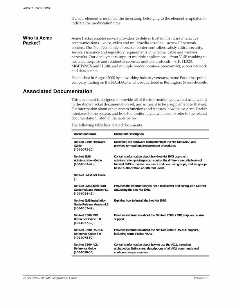
ABOUT THIS GUIDE
If a sub-element is modified the timestamp belonging to the element is updated to indicate the modification time.
Who is Acme Packet?
Acme Packet enables service providers to deliver trusted, first class interactive communications—voice, video and multimedia sessions—across IP network borders. Our Net-Net family of session border controllers satisfy critical security, service assurance and regulatory requirements in wireline, cable and wireless networks. Our deployments support multiple applications—from VoIP trunking to hosted enterprise and residential services; multiple protocols—SIP, H.323, MGCP/NCS and H.248; and multiple border points—interconnect, access network and data center.
Established in August 2000 by networking industry veterans, Acme Packet is a public company trading on the NASDAQ and headquartered in Burlington, Massachusetts.
Associated DocumentationThis document is designed to provide all of the information you would usually find in the Acme Packet documentation set, and is meant to be a supplement to that set. For information about other system functions and features, how to use Acme Packet interfaces to the system, and how to monitor it, you will need to refer to the related documentation listed in the table below.
The following table lists related documents.
Document Name Document Description
Net-Net 9200 Hardware Guide (400-0073-10)
Describes the hardware components of the Net-Net 9200, and provides removal and replacement procedures.
Net-Net EMS Administration Guide(400-0083-42)
Contains information about how Net-Net EMS users with administration privileges can control the different security levels of Net-Net EMS to: create new users and new user groups, and set group-based authorization at different levels.
Net-Net EMS User Guide ( )
Net-Net EMS Quick Start Guide Release Version 4.2(400-0058-42)
Provides the information you need to discover and configure a Net-Net SBC using the Net-Net EMS.
Net-Net EMS Installation Guide Release Version 4.2(400-0059-42)
Explains how to install the Net-Net EMS.
Net-Net 9200 MIB Reference Guide 5.0(400-0077-50)
Provides information about the Net-Net 9200’s MIB, trap, and alarm support.
Net-Net 9200 RADIUS Reference Guide 5.0(400-0078-50)
Provides information about the Net-Net 9200’s RADIUS support, including Acme Packet VSAs.
Net-Net 9200 ACLI Reference Guide(400-0076-50)
Contains information about how to use the ACLI, including alphabetical listings and descriptions of all ACLI commands and configuration parameters.
20 Net-Net 9200 EMS Configuration Guide Version 6.0
ABOUT THIS GUIDE
Customer Questions, Comments, or Suggestions
Acme Packet is committed to providing our customers with reliable documentation. If you have any questions, comments, or suggestions regarding our documentation, please contact your Acme Packet customer support representative directly or email [email protected].
Contact Us Acme Packet 71 Third AvenueBurlington, MA 01803 USAt 781 328 4400f 781 425 5077www.acmepacket.com
Version 6.0 Acme Packet, Inc. Technical Publications 21

ABOUT THIS GUIDE
22 Net-Net 9200 EMS Configuration Guide Version 6.0

3 Getting Started
IntroductionPrior to configuring your Net-Net EMS for service, we recommend that you review the information and procedures in this chapter. It contains information that requires you to use the Acme Packet command line interface (ACLI) for some of the procedures. These procedures cannot be managed through Net-Net EMS.
ACLI-only procedures include the following:
• Most installation and start-up procedures
• Changing most boot parameters
• Working with licenses
Using the Net-Net EMS to Configure the Net-Net SBC
You must create all new configurations and make edits to existing configurations in the Inactive configuration branch of the Net-Net EMS navigation tree. You then save and activate the Inactive configuration to apply the new configurations and edits on your Net-Net SBC.
Refer to the Net-Net EMS User Guide for detailed instructions.
Configuration Timestamp
You might see the following information on some of the configuration windows:
This is a configuration timestamp that displays last modified information for configuration changes made using Net-Net EMS.
When you make configuration changes to elements, the Last modified by field displays the following information:
• Net-Net EMS identifier
• Name of the user that made the modification
• IP address of the host machine upon which Net-Net EMS is running
• Relevant time zone information to specify how to interpret the timestamp in the Last modified date field.
For example:
EMS_admin_172.30.80.2_UTC
The Last modified date is displayed in the string date/time format, YYYY-MM-DD HH:MM:SS. For example 2007-11-07 15:16:05. When you make configuration changes using the Net-Net EMS, the date timestamp is specified in UTC.
Version 6.0 Acme Packet, Inc. Technical Publications 21
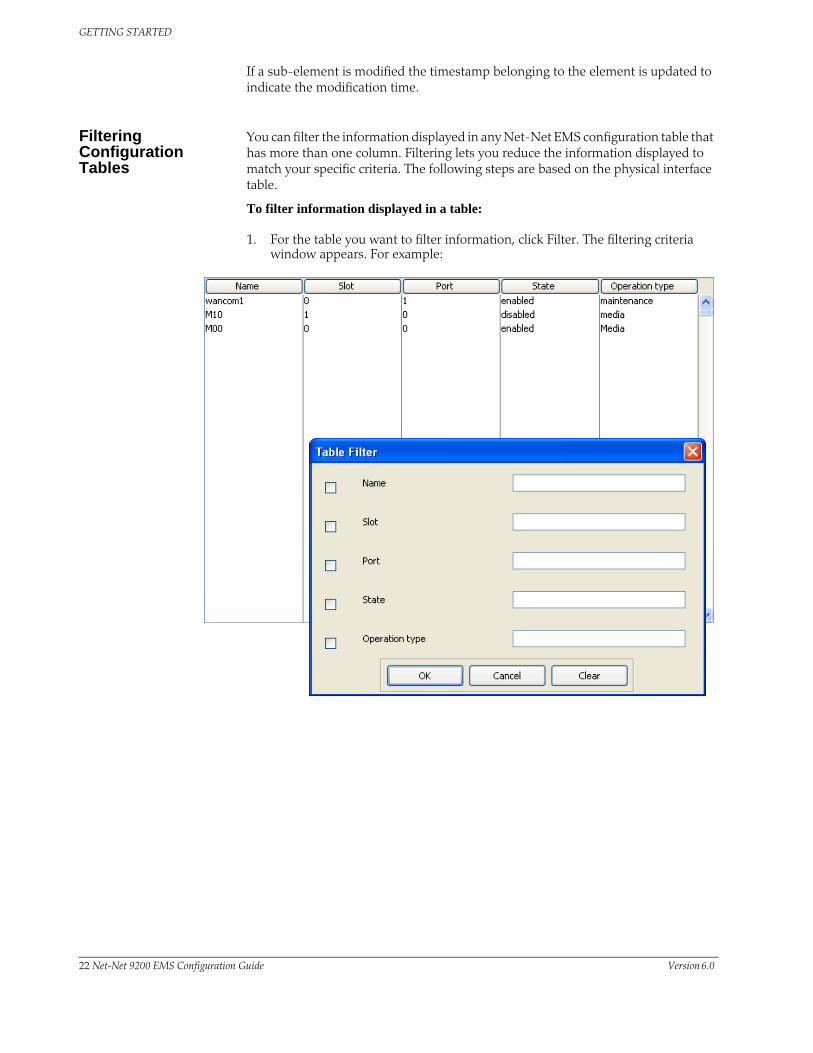
GETTING STARTED
If a sub-element is modified the timestamp belonging to the element is updated to indicate the modification time.
Filtering Configuration Tables
You can filter the information displayed in any Net-Net EMS configuration table that has more than one column. Filtering lets you reduce the information displayed to match your specific criteria. The following steps are based on the physical interface table.
To filter information displayed in a table:
1. For the table you want to filter information, click Filter. The filtering criteria window appears. For example:
22 Net-Net 9200 EMS Configuration Guide Version 6.0

GETTING STARTED
2. Click the checkbox of the filter criterion you want to apply. For example:
3. Click OK. The information displayed in the table changes to reflect your choices. For example:
The filtering criteria are displayed above the table. The Filter button toggles to Modify Filter and a Clear Filter button also appears.
4. Click Modify filter if you want to edit your criteria. Or click Clear filter to set the table back to its original state.
Version 6.0 Acme Packet, Inc. Technical Publications 23

GETTING STARTED
Installation and Start-UpAfter you have completed the hardware installation procedures outlined in the Net-Net System Hardware Installation Guide, you are ready to establish a connection to your Net-Net SBC. Then you can load the Net-Net SBC software image you want to use and establish basic operating parameters.
Hardware Installation Summary
Installing your Net-Net SBC in your rack requires the steps summarized here. This list is only an overview and is not designed to substitute for following the detailed procedures in the Net-Net System Hardware Installation Guide.
1. Unpacking the Net-Net SBC
2. Installing the Net-Net SBC into your rack
3. Installing power supplies
4. Installing fan modules
5. Cabling the Net-Net SBC system
Make sure you complete installation procedures fully and note the safety warnings to prevent physical harm to yourself and/or damage to your Net-Net SBC.
Connecting to Your Net-Net SBC System
You can connect to your Net-Net SBC either through a direct console connection, or by creating a remote telnet or SSH session. Both of these access methods provide you with the full range of configuration, monitoring, and management options.
Note: By default, Telnet and FTP connections to the management interfaces on your Net-Net system are enabled.
Local Connections and Time-outs
Using a serial connection, you can connect your laptop or PC directly to the Net-Net SBC. If you use a laptop, you must take appropriate steps to ensure grounding.
One end of the cable plugs into your terminal, and the other end plugs into the bottom RJ-45 port on right side of the MIU where the word “console” is printed in white; this provides a serial connection to the SPU opposite the MIU into which you connect. (The top RJ-45 port is used for dry contact alarms.)
To set up a console connection to your Net-Net SBC:
1. Set the connection parameters for your terminal to the default boot settings:
– Baud rate: 115,200 bits/second
– Data bits: 8
– Parity: No
– Stop bit: 1
– Flow control: None
2. Use a serial cable to connect your PC to the Net-Net SBC.
The serial port is located on the rear of the Net-Net SBC chassis, on right side of the MIU. It is labeled “console” in white letters, and sits directly to the left of the USB ports.
24 Net-Net 9200 EMS Configuration Guide Version 6.0

GETTING STARTED
Refer to the following picture, which shows the exact location, with the serial cable inserted.
3. Power on your Net-Net SBC.
4. Enter the appropriate password information when prompted to log into User mode of the ACLI.
Telnet Remote Connections and Time-outs
You can also telnet to your Net-Net SBC. Using remote telnet access, you can provision the Net-Net SBC remotely through the management interface over IP.
The Net-Net SBC can support up to five concurrent telnet sessions. However, only one user can carry out configuration tasks at one time.
Note: Telnet does not offer a secure method of sending passwords. Using telnet, passwords are sent in clear text across the network.
To Telnet to your Net-Net SBC, you need to know the IP address of its administrative interface. The IP address of your Net-Net SBC is found by checking the inet on ethernet value in the boot parameters.
Version 6.0 Acme Packet, Inc. Technical Publications 25

GETTING STARTED
Connecting Using Telnet through Net-Net EMS
If you want to switch from configuring Net-Net SBCs in the Net-Net EMS to using the ACLI, you can connect through Telnet to the Net-Net SBC. You can then login in to continue working using the ACLI.
To connect using Telnet:
1. In the Active configurations area, right click the name of the Net-Net SBC. A list of options appears:
2. Click Telnet to SD system. The Telnet window appears:
3. Login to the Net-Net SBC. See the Net-Net 6.0 ACLI Reference Guide for details about logging in and using the ACLI. See the Net-Net SD 6.0 Configuration Guide for details about configuring a Net-Net SBC using the ACLI.
4. Save the configuration to the Net-Net SBC to activate it.
26 Net-Net 9200 EMS Configuration Guide Version 6.0

GETTING STARTED
SSH Remote Connections
For increased security, you can connect to your Net-Net SBC using SSH. An SSH client is required for this type of connection.
When you connect to the Net-Net SBC for the first time using an SSH client, you will encounter a prompt asking you to accept the Net-Net SBC’s keys. Once you accept them, then your client will know about your Net-Net SBC. You will not be prompted about keys again unless the Net-Net SBC’s flash memory is cleared.
The following is a sample of how certain SSH clients work; the one you select might differ.
To initiate an SSH connection to the Net-Net SBC:
1. Open your SSH client.
2. At the prompt in the SSH client, type the ssh command, a <Space>, the IP address of your Net-Net SBC, and then press <Enter>.
The SSH client prompts you for a password before connecting to the Net-Net SBC. Any password will be accepted.
After it is authenticated, an SSH session is initiated and you can continue with tasks in User mode or enable Superuser mode.
SSH Through Net-Net EMS
To connect using Telnet:
1. In the Active configurations area, right click the name of the Net-Net SBC. A list of options appears:
2. Click SSH to device. The SSH Authorization required window appears.
3. User name—Enter a username.
Version 6.0 Acme Packet, Inc. Technical Publications 27

GETTING STARTED
4. Password—Enter a password..
5. Click Login..
28 Net-Net 9200 EMS Configuration Guide Version 6.0

GETTING STARTED
System Boot When your Net-Net SBC boots, the boot parameters tell the SPU master core what specific software image to load and where to obtain it. The SPU master core performs operations using this image; these involve decompression and extraction of the image contents.
After these operations have successfully completed, all other cores associated with the Net-Net SBC cards use an internal control network to boot from the SPU master core. The internal network functions seamlessly so there is no need for external network access or intervention on your part.
During the booting process, the following information about the tasks and settings for the system appear:
• System boot parameters
• From which location the software image is being loaded: an external device or internal flash memory
• Hardware information including about the cards installed in chassis
• Each card starting up and registering that it is active complete
• Requisite tasks that the system is starting
• Any errors that might occur during the loading process
• Currently licensed capabilities of your Net-Net SBC
At the end of the loading process, the message READY TO RUN! appears.
Version 6.0 Acme Packet, Inc. Technical Publications 29

GETTING STARTED
Net-Net SBC Boot ParametersBoot parameters specify a what information your Net-Net SBC uses at boot time when it prepares to run applications. The Net-Net SBC’s boot parameters:
• Show the Net-Net system’s IP address for the management interface
• Determine what software image a Net-Net SBC uses and from where it boots that image
• Set up an external FTP server’s username and password for transferring an image to the Net-Net SBC using FTP
In addition to providing details about the Net-Net SBC’s boot parameters, this section explains how to view, edit, and implement them.
Note: Allow your system to boot fully before you view or start to change boot parameters; both SPUs need to have assumed their roles. Otherwise, the boot parameters you view might not be accurate; if you change any of them, then setting them might fail.
Displaying Boot Parameters
You can display the boot parameters from the ACLI using the show bootparams command.
To display boot parameters in the ACLI:
1. At the command-line prompt (either in User or Superuser mode), type show bootparams and press <Enter>.
The boot parameters will appear as they do in the following example.
ACMEPACKET> show bootparams
boot device : eth2
processor number : 0
host name : acmepacket8
file name : nnD500.tar
inet on ethernet (e): 10.0.1.57:ffff0000
inet on backplane (b): 0.0.0.0
host inet (h) : 10.0.1.5
gateway inet (g) : 10.0.0.1
user (u) : vxftp
ftp password (pw) : vxftp
flags (f) : 0x0
target name (tn) : ACMEPACKET
startup script (s) :
other (o) :
ACMEPACKET>
30 Net-Net 9200 EMS Configuration Guide Version 6.0

GETTING STARTED
The following table defines each of the Net-Net SBC’s boot parameters.
Boot Parameter Description
boot device Management interface name and port number of the device from which an image is downloaded (e.g., wancom0) from an external device.
processor number Processor number on the backplane.
host name Name of the boot host used when booting from an external device.
file name Name of the image file to be booted; can be entered with the filenamepath.
If you are booting from the flash memory, this filename must always match the filename that you designate when you FTP the image from the source to the Net-Net SBC.
When booting from flash memory, this filename must start with: /tffs0/ (referring to /boot); for example, /tffs0/sd200.gz.
inet on ethernet (e) IP (external) address of the Net-Net SBC.
In this parameter, the subnet mask ffff0000 = 255.255.0.0. You set this IP address and netmask combination in the following format: 10.21.3.5:ffff0000.
inet on backplane (b) Internet address of the backplane interface.
This parameter can have an optional subnet mask and/or lease timinginformation, such as e (inet on ethernet) does.
host inet (h) Internet address of the boot host used when booting from an external device.
gateway inet (g) Internet address of the gateway to the boot host.
Leave this parameter blank if the host is on the same network.
user (u) FTP username on the boot host.
ftp password (pw) FTP password for the FTP user on the boot host.
flags (f) Codes that signal the Net-Net SBC from where to boot. Also signals theNet-Net system about which file to use in the booting process. This sequence always starts with 0x (these flags are hexadecimal).
Enter the value 0x0 for this parameter to indicate that your system is booting from a .tar file (default).
target name (tn) Name of the Net-Net SBC as it appears in the system prompt. For example, ACMEPACKET> or ACMEPACKET#. You need to know the target name if you are setting up an HA node.This name is required to be unique among Net-Net SBCs in your network.
startup script (s) For Acme Packet use only.
other (o) For Acme Packet use only.
Version 6.0 Acme Packet, Inc. Technical Publications 31

GETTING STARTED
Changing Boot Parameters
The Net-Net SBC supports different ways that you can access and change its boot parameters. You can change them on your Net-Net SBC by editing them in the ACLI and then rebooting your system, or by interrupting a boot in progress to make your edits and then rebooting your system. This section describes both methods.
Note: Changes to boot parameters do not go into effect until you reboot the Net-Net SBC.
Using the ACLI You can access and change the boot parameters in ACLI Superuser mode using the set bootparams command and then rebooting your system. Once you have scrolled through and made any necessary changes, the system informs you that your changes will not be implemented until you reboot the system.
To access and change boot parameters from the ACLI:
1. In Superuser mode, type configure terminal and press <Enter>. For example:
ACMEPACKET# configure terminal
2. Type bootparam and press <Enter>. The boot device parameters appear.
ACMEPACKET(configure)# bootparam
'.' = clear field; '-' = go to previous field; ^D = quit
boot device : wancom0
To navigate through the boot parameters, press <Enter> and the next parameter appears on the following line.
You can navigate through the entire list this way. To go back to a previous line, type a hyphen (-) and then pressing <Enter>. Any value that you enter entirely overwrites the existing value and does not append to it.
3. To change a boot parameter, type the new value you want to use next to the old value. For example, if you want to change the image you are using, type the new filename next to the old one. You can clear the contents of a parameter by typing a period and then pressing <Enter>.
ACMEPACKET(configure)# bootparam
'.' = clear field; '-' = go to previous field; ^D = quit
boot device : wancom0
processor number : 0
host name : goose
file name : /tffs0/sd210.gz /tffs0/sd400.gz
When you have scrolled through all of the boot parameters, the system prompt for the configure terminal branch appears.
ACMEPACKET(configure)#
4. Exit the configure terminal branch.
5. Reboot your Net-Net SBC for the changes to take effect.
The ACLI reboot and reboot force commands initiate a reboot. With the reboot command, you must confirm that you want to reboot. With the reboot force command, you do not have make this confirmation.
ACMEPACKET# reboot force
The Net-Net SBC completes the full booting sequence. If necessary, you can stop the auto-boot at countdown to fix any boot parameters.
32 Net-Net 9200 EMS Configuration Guide Version 6.0

GETTING STARTED
If you have configured boot parameters correctly, the system prompt appears and you can go ahead with configuration, management, or monitoring tasks.
6. If you have configured the boot parameters incorrectly, the Net-Net SBC goes into a booting loop and an error message appears.
Error loading file: errno = 0x226.
Can't load boot file!!
If this happens, hit the space bar on your keyboard to stop the loop, find and correct your error, and reboot your system.
Interrupting Boot in Progress
You can interrupt a boot in progress to access and edit boot parameters by using the ACLI reboot command to reboot the system, and then halting the boot process.
Be advised that if you use this method, the display from the ALCI show bootparams command might not be updated until role assignment.
Your screen shows a help menu and the first boot parameter (boot device). You can then navigate and edit boot parameters as needed.
To access and change boot parameters by interrupting a boot in progress:
1. When the Net-Net SBC is in the process of booting, you can press the space bar on your keyboard to interrupt when you see the following message appear:
Press the space bar to stop auto-boot...
2. After you stop the booting process, you can enter a “c” to change the boot parameters or the @ (at-sign) to continue booting.
[Acme Packet Boot]: c
'.' = clear field; '-' = go to previous field; ^D = quit
boot device : wancom0
To navigate through the boot parameters, press <Enter> and the next parameter appears on the following line.
You can navigate through the entire list this way. To go back to a previous line, type a hyphen (-) and then pressing <Enter>. Any value that you enter entirely overwrites the existing value and does not append to it.
3. To change a boot parameters, type the new value you want to use next to the old value. For example, if you want to change the image you are using, type the new filename next to the old one.
ACMEPACKET(configure)# bootparam
'.' = clear field; '-' = go to previous field; ^D = quit
boot device : wancom0
processor number : 0
host name : goose
file name : /tffs0/sd210.gz /tffs0/sd400.gz
4. After you have scrolled through the complete list of boot parameters, you return to the boot prompt. To reboot with your changes taking effect, type @ (the at-sign) and press <Enter>.
[Acme Packet Boot]: @
The Net-Net SBC completes the full booting sequence unless you have made an error setting the boot parameters.
Version 6.0 Acme Packet, Inc. Technical Publications 33

GETTING STARTED
If you have configured boot parameters correctly, the system prompt appears and you can go ahead with configuration, management, or monitoring tasks.
5. If you have configured the boot parameters incorrectly, the Net-Net SBC goes into a booting loop and an error message appears.
Error loading file: errno = 0x226.
Can't load boot file!!
If this happens, hit the space bar on your keyboard to stop the loop, find and correct your error, and reboot your system.
Virtual IP Address for Management
You can assign a virtual IP address to the Net-Net SBC, allowing you to set one IP address for management of the system. When you configure this address, RADIUS will use it; if you do not, then RADIUS uses the boot address. Syslog also uses this address if you configure it.
To assign a virtual IP address to your Net-Net SBC on the Net-Net EMS:
1. Click the Net-Net SBC system your are configuring in the Net-Net EMS navigation tree.
The Net-Net SBC system window appears in the display pane.
2. Click the Maintenance tab.
3. Virtual IP address—Enter the virtual IP address.
4. Virtual IP gateway—Enter the virtual IP gateway.
5. Click Apply.
34 Net-Net 9200 EMS Configuration Guide Version 6.0

GETTING STARTED
Setting Up System BasicsBefore configuring and deploying your Net-Net system, you might want to establish some basic attributes such as adding and removing NTP servers from your system configuration and configuring time zone information on your system.
NTP Synchronization
Setting NTP synchronizes both hardware and software clocks with the NTP server(s) you specify, and it keeps the Net-Net SBC internally synchronized.
The Net-Net SBC acts essentially as a cluster of NTP servers with the master core at its center. The other system cores poll the master core, which keeps itself synchronized with the NTP server(s) that you configure. This means that if the master core for some reason fails to be synchronized with the NTP server(s), the Net-Net SBC’s components are still synchronized with the master core and with each other.
To set NTP synchronization:
1. Click the Net-Net SBC system your are configuring in the Net-Net EMS navigation tree.
The Net-Net SBC system window appears in the display pane.
2. Click the Management tab and the General sub-tab.
3. Scroll to NTP server.
4. Click Add. The NTP server window appears.
5. NTP server IP address—Enter the IP address of the server and click OK. The new server name appears in the IP address list.
6. Reboot the Net-Net SBC.
Version 6.0 Acme Packet, Inc. Technical Publications 35

GETTING STARTED
Configuring the Time Zone
This section explains how to configure the time zone on your Net-Net SBC using the Net-Net EMS.
To configure the timezone:
1. Click the Net-Net SBC system your are configuring in the Net-Net EMS navigation tree.
The Net-Net SBC system window appears in the display pane.
2. Click the Management tab and the Timezone subtab.
3. Name—Enter the name of the time zone. You can enter no more than ten characters.
4. Difference between time zone and UTC—Enter the number of minutes representing the difference between the time zone you are setting and UTC. Enter a positive number of the time zone you are setting if it is behind UTC, and a negative number if the time zone is ahead of UTC.
• minimum: -720 (12 hours behind UTC)
• maximum: 720 (12 hours ahead of UTC)
5. Month that DST starts—Enter the number corresponding to the month that daylight saving time (DST) starts. The default is 0.
6. Day of the month when DST starts—Enter the number of the day of the month when DST starts. The default is 0.
7. Hour of the day when DST starts—Enter the hour of the day when DST starts. The default is 0.
8. Month that DST ends—Enter the number corresponding to the month that DST ends. The default is 0.
9. Day of the month when DST ends—Enter the day of the month when DST ends. The default is 0.
36 Net-Net 9200 EMS Configuration Guide Version 6.0

GETTING STARTED
10. Hour of the day when DST ends—Enter the hour of day when DST ends. The default is 0.
11. Click Apply.
Version 6.0 Acme Packet, Inc. Technical Publications 37
GETTING STARTED
About Your Net-Net SBC ImageYour Net-Net SBC arrives with the most recent, manufacturing-approved run-time image installed on the flash memory. If you want to use this image, you can install your Net-Net system as specified in the Net-Net 9200 Hardware Installation Guide, establish a connection to it, and then begin to configure it.
If you want to use an image other than the one installed on your Net-Net SBC when it arrives, you can use the information in this section to obtain and install it.
Obtaining a New Image
You can download software images onto the platform of your Net-Net SBC from various sources. You can take any one of the following actions:
• Obtain an image from the FTP site and directory where you and/or your Acme Packet customer support representative has placed images available for use. This may be a special server that you use expressly for images, backups, etc.
• Obtain an image from your Acme Packet customer support representative, who will transfer it to your system.
Regardless source you use to obtain the image, you need to use FTP or SFTP to copy it from its source to your Net-Net SBC.
Using FTP to Copy an Image on Your Net-Net SBC
This section describes how to use FTP to copy an image to your Net-Net SBC. Copying the image can take some time, so wait for the process to complete.
To copy an image on your Net-Net SBC using FTP:
1. Go to the directory where the image is located.
2. Check the IP address of the Net-Net SBC’s management port (wancom0). (You might think of this as a management address since it is used in the management of your Net-Net SBC.)
3. Create the connection to your Net-Net SBC. In your terminal window, type ftp and the IP address of your Net-Net SBC’s management port (wancom0), and then press <Enter>. Once a connection has been made, a confirmation note appears followed by the FTP prompt.
4. When prompted, enter your FTP username and FTP password information. The username is always user, and the password is the same as the one you use for the User mode login.
5. Go to the directory where you want to put the image. The /boot directory is used for the on-board system flash memory. If you do not put the image in this directory, the Net-Net SBC will not find it.
6. From the FTP prompt:
6a. Change the directory to /boot.ftp> cd “/boot”
6b. Invoke binary mode.ftp> binary
38 Net-Net 9200 EMS Configuration Guide Version 6.0

GETTING STARTED
Caution: Be sure to use binary transfer mode. If you do not, all transfers will be corrupted.
6c. At the FTP prompt, enter the put command, a <Space>, the name of the image file, and then press <Enter>.ftp> put [file name]
Confirmation that the connection is opening and that transfer is taking place appears.
6d. After the file transfer is complete, you can quit.ftp> quit
7. Now you are ready to boot the Net-Net SBC using the image you just transferred.
In the ACLI, change any boot configuration parameters that need to be changed. It is especially important to change the filename boot parameter to the filename you used during the FTP process. Otherwise, your system will not boot properly.
8. Reboot your Net-Net SBC.
9. Your Net-Net SBC runs through its loading processes and return you to the ACLI login prompt.
System Image Filename
The system image file name is a name you set for the image. This is also the file name the boot parameters uses when booting your system. This file name must match the file name specified in the boot parameters. When you use it in the boot parameters, it must always start with /code/images to signify that the Net-Net system is booting from the /code directory.
If the file name set in the boot parameters does not point to the image you transferred to the Net-Net SBC, then you could not only fail to load the appropriate image, but you could also load an image from a different directory or one that is obsolete for your purposes. If this happens, you can stop the countdown, enter the appropriate file name, and reboot the Net-Net SBC.
Version 6.0 Acme Packet, Inc. Technical Publications 39

GETTING STARTED
Booting an Image on Your Net-Net SBCYou can either boot your Net-Net SBC from the system’s flash memory or from an external device. Both locations can store images from which the system can boot. This section describes both booting methods.
For boot parameters to take effect, you must reboot your Net-Net SBC. Since a reboot stops call processing, Acme Packet recommends performing tasks that call for a reboot during off-peak maintenance hours.
Booting from Flash Memory
Once you have installed an image, you can boot your Net-Net SBC from its flash memory. With the exception of testing an image before you install it on the flash memory, this is generally the method you use for booting.
To boot from your Net-Net SBC flash memory:
1. Confirm that the boot parameters are set up correctly, and make any necessary changes.
2. Change any boot configuration parameters that you need to change. It is especially important to change the file name boot configuration parameter correctly.
boot device : eth2
unit number : 2
processor number : 0
host name : boothost
file name : /code/images/nnD500.tar
inet on ethernet (e) : 124.40.1.7
host inet (h) : 124.40.0.3
gateway inet (g) : 124.40.0.1
user (u) : vxftp
ftp password (pw) : vxftp
flags (f) : 0x0
target name (tn) : ACMEPACKET
startup script (s) :
3. Reboot your Net-Net SBC. The boot process resembles the one in the following example.
TFFS mounting /code...
/code mounted.
Extracting from fd 4
extract acmeOS_cpu0.gz
extracting file acmeOS_cpu0.gz, size 4536969 bytes, 8862 blocks
done extracting: acmeOS_cpu0.gz
extract acmeOS_cpu1.gz
extracting file acmeOS_cpu1.gz, size 4538349 bytes, 8864 blocks
done extracting: acmeOS_cpu1.gz
end of buffers (2), done
Decompressing CPU0 image... 16653523 bytes uncompressed.
CPU0: 4 + 14011920 + 3619152
Decompressing CPU1 image... 16653523 bytes uncompressed.
CPU1: 4 + 14011920 + 3619152
/code synced and unmounted
Starting CPU0 at 0x80020000...
40 Net-Net 9200 EMS Configuration Guide Version 6.0

GETTING STARTED
[Display abbreviated; full booting displays appears on your screen.]
If you have made an error in configuring boot parameters, the Net-Net SBC issues an error message. Check your boot parameters, and try to reboot using the corrected set.
4. You are returned to the ACLI login prompt. To continue with system operations, enter the required password information.
Booting from an External Device
Booting from an external device means that your Net-Net SBC connects to a server to retrieve the boot image at boot time. Rather than using an image stored on your system’s flash memory, it downloads the image from the external device each time it reboots.
When you are testing a new image before putting it on your Net-Net SBC, you might want to boot from an external device. Ordinarily, you would not want to boot an image on your Net-Net SBC this way.
To boot an image from an external device:
1. Confirm that the Net-Net SBC is cabled to the network from which you are booting. The image is loaded from the source using FTP.
2. Log into the system you want to mount.
3. On the Net-Net SBC, configure the information for the boot parameters and confirm the following:
• boot device—Device to which you will FTP
• This parameter value must contain the name of the applicable management interface, and then the number of the appropriate 10/100 port. Usually, this value is wancom0.
• file name—Name on the host of the file containing the image
• The image file must exist in the home directory of the “user” on the image source.
• host inet—IP address of the device off of which you are booting
• gateway inet—IP address of the gateway to use if the device from which you are booting is not on the same network as your Net-Net SBC
• user—Username for the FTP account on the boot host
• password—Password for the FTP account on the boot host
• target name—Uniquely identifies your Net-Net SBC, and sets the name you see for your system at the beginning of the command line, e.g., ACMEPACKET#.
4. Reboot your Net-Net SBC.
5. You are returned to the ACLI login prompt. To continue with system operations, enter the required password information.
Version 6.0 Acme Packet, Inc. Technical Publications 41

GETTING STARTED
Software LicensingThe components of the Net-Net SBC software are licensed by Acme Packet, Inc. for your use. In order to use these components and deploy their related services in your network, you must have a valid license. There are two types of Acme Packet licenses, and you can have one of each type of license installed on your system at one time:
• Permanent—This license has no expiration and covers all of the features on your Net-Net SBC. If you try to add a new permanent license, the Net-Net SBC overwrites the existing permanent license.
• Temporary—This license expires at specific date and time; it is active when the current dates falls within the license’s start and end dates. It does not matter when the expiration date occurs; every license with any expiration date is considered temporary. If you try to add a new temporary license, the Net-Net SBC overwrites the existing temporary license.
Licenses can be activated and deactivated in real time. They are tied to specific Net-Net SBCs (by serial number) and cannot be transferred from one Net-Net SBC to another. Before you change your licensing, the Net-Net SBC prompts you to verify the override of the old license.
Only one license can be active on the Net-Net SBC at one time. This means that if you want to change your licensed Acme Packet features, you must obtain a new license that will overwrite the one previously installed.
Conditions under which you might want or need a new license include:
• Changing from a temporary to a permanent license
• Adding features to your license
• Removing features from your license
• Using new features on a trial basis with a temporary license
The following software components, interfaces, and features are licensed. If you do not have a license for a given component, interfaces, or feature, its configuration parameters are not visible.
The Net-Net SBC supports protocol-specific session capacity licensing.
Licence Description
Licence Description
SIP Enables SIP signaling and SIP session capacity.
QoS Enables measurement for QoS (jitter, packet latency, and packet loss) on the Net-Net SBC.
Routing policies Establishes routing policies on the Net-Net SBC.
Load balancing Establishes distribution of traffic across gateways, application servers,softswitches, etc.
Load balancing Establishes distribution of traffic across gateways, application servers,softswitches, etc.
Accounting Establishes RADIUS servers to which the Net-Net SBC can make connections and send CDRs.
42 Net-Net 9200 EMS Configuration Guide Version 6.0

GETTING STARTED
This differs from the way that session capacity works for the Net-Net 4250. On that platform, you license a certain number of sessions that all protocols on the system use. The protocols can use them on a first-come, first-served basis.
For the Net-Net SBC, the fact that session capacity is protocol-specific means that the sessions for a specific protocol are limited to that number, and you can license the number of protocol-specific sessions best suited to your needs.
Note: Currently only SIP and SIP session capacity are supported.
The Net-Net SBC checks session capacity on a per-call basis. Before it sets up a call, the Net-Net SBC confirms that there is adequate capacity for a call of that protocol type. Then it checks the capacity of the entire system and allows the call.
Unlicensed Net-Net SBCs
If you log into a Net-Net SBC that is not licensed, you are warned that no licenses exist and that you need to enter a valid one. Until you enter a valid license, you can configure general system parameters, but not parameters for protocols and features.
When your Net-Net SBC arrives, you will need to obtain a key to activate the licenses for functionality you want to use. This original set of features is enabled with one key that you obtain from Acme Packet customer support at [email protected].
Obtaining a License
If you choose to change the licensed functionality to your Net-Net system, you need to obtain a new license from Acme Packet.
To obtain additional licenses, contact your customer support or sales representative directly or at [email protected]. You can request the changes that you want to make for your license, and Acme Packet will issue a new license to you. Then you can overwrite the old license with your new one that presents the updated feature set.
When you obtain a license, you need to provide Acme Packet with the serial number of your Net-Net system.
Trial Licenses Acme Packet offers trial license periods for software components, allowing you to test a features before deploying them. Temporary licenses are used for this purpose.
Trial licenses are available for the same components listed in the Supported Components (35) section, but they only last for preset periods. After trial licenses expire, their functionality stops. At that time, you can purchase a permanent license for the software components on your Net-Net SBC to continue using system functionality and features.
Adding Licenses Once you have obtained a key for the license, you can add the license to your Net-Net SBC. To use the license, you also need to activate it.
To add and activate a license on your Net-Net SBC:
1. In Superuser mode, enter the system branch of the configure terminal menu. For example:
ACMEPACKET# configure terminal
ACMEPACKET (configure)# system
ACMEPACKET (system)# license
Version 6.0 Acme Packet, Inc. Technical Publications 43

GETTING STARTED
2. Using the add command and the key generated by Acme Packet, activate the license on your Net-Net SBC.
ACMEPACKET (license)# add sl25o39pvtqhas4v2r2jc1oaen9e01o21b1dmh3
3. Confirm that the license has been activated by using the ACLI show command within the license configuration.
The example below shows how you can have one license of each type (permanent and temporary) installed on your system.
The first license is permanent; note that it does not have an expiration date. The second license is temporary, and the example shows that it has already expired. If you wanted to resume using the functionality covered by the temporary license on a trial/temporary basis, you would need to contact Acme Packet customer support and obtain a new license. You have the option of obtaining a new temporary license for the feature, or adding the functionality to your permanently licensed feature set.
license# show
License #1: ad8739ef833ea48812f949ea872338dfe0923ac
32000 sessions, SIP(32000), QOS, Routing, Load Balancing, Accounting
no expiration
installed at 12:34:42 MAR 01 2006
License #2: fe3589ef833ea4884923749ea872338dfe8733ac
1000 sessions, SIP(1000) ACP
expired at 23:59:59 MAY 08 2006
installed at 12:35:43 MAR 01 2006
4. To activate your license, type the activate-config command and press <Enter>. The Net-Net SBC then enables any of the processes that support associated features.
ACMEPACKET# activate-config
Deleting Licenses You can delete licenses from your Net-Net SBC, including licenses that have not expired. If you want to delete a license that has not expired, you need to confirm the deletion.
To delete a license from the Net-Net SBC:
1. In Superuser mode, enter the system branch of the configure terminal menu. For example:
ACMEPACKET# configure terminal
ACMEPACKET(configure)# system
ACMEPACKET(system)# license
2. Type the no command and press <Enter>. A list of possible license to delete appears.
ACMEPACKET(license)# no fe3589ef833ea4884923749ea872338dfe8733ac
3. If the license has not expired, you are be asked to confirm the deletion.
Delete unexpired license [y/n]?: y
ACMEPACKET(license)#
When you show the licenses, the one you deleted should no longer appear on the list.
4. To clear the license, type the activate-config command and press <Enter>. The Net-Net system then disables any of the processes that support associated features.
44 Net-Net 9200 EMS Configuration Guide Version 6.0

GETTING STARTED
ACMEPACKET# activate-config
Expiration When a temporary license expires, you are no longer able to use the features associated with it. The Net-Net SBC automatically disables all associated processes.
To avoid a temporary license unexpectedly expiring and therefore potentially disrupting service, we recommend that you track expiration dates and renew licenses well in advance of expiration. You also have the option of adding this functionality to the feature set that you license permanently, thereby avoiding the risk or expiration altogether.
Expired temporary licenses appear in your Net-Net SBC ACLI display until you delete them, though you cannot use the features associated with them.
Viewing Licenses There are two ways to view licenses in the ACLI.
• You can use the show features command at the main ACLI user prompt.
ACMEPACKET# show features
32000 SIP sessions
SIP, QOS, Routing, Load Balancing, Accounting
ACMEPACKET#
• Within the license menu, use the show command to see all licenses with detailed information, including: license keys, enabled features, expiration status, expiration date (if any), and installation date.
license# show
License #1: ad8739ef833ea48812f949ea872338dfe0923ac
32000 sessions, SIP(32000), QOS, Routing, Load Balancing, Accounting
no expiration
installed at 12:34:42 MAR 01 2006
License #2: fe3589ef833ea4884923749ea872338dfe8733ac
1000 sessions, SIP(1000)
expired at 23:59:59 MAY 08 2006
installed at 12:35:43 MAR 01 2006
Version 6.0 Acme Packet, Inc. Technical Publications 45

GETTING STARTED
RADIUS AuthenticationA security feature that extends beyond the designation of ACLI User and Superuser privileges, the User Authentication and Access control feature supports authentication using your RADIUS server(s). In addition, you can set two levels of privilege, one for all privileges and more limited set that is read-only.
User authentication configuration also allows you to use local authentication, localizing security to the Net-Net SBC ACLI log-in modes. These modes are User and Superuser, each requiring a separate password.
The components involved in the RADIUS-based user authentication architecture are the Net-Net SBC and your RADIUS server(s). In these roles:
• The Net-Net SBC restricts access and requires authentication via the RADIUS server; the Net-Net SBC communicates with the RADIUS server using either port 1812 or 1645, but does not know if the RADIUS server listens on these ports
• Your RADIUS server provides an alternative method for defining Net-Net SBC users and authenticating them via RADIUS; the RADIUS server supports the VSA called ACME_USER_CLASS, which specifies what kind of user is requesting authentication and what privileges should be granted
How It Works When RADIUS user authentication is enabled, the Net-Net SBC communicates with one or more configured RADIUS servers that validates the user and specifies privileges. On the Net-Net SBC, you configure:
• What type of authentication you want to use on the Net-Net SBC
• If you are using RADIUS authentication, you set the port from which you want the Net-Net SBC to send messages
• If you are using RADIUS authentication, you also set the protocol type you want the Net-Net SBC and RADIUS server to use for secure communication
Although most common set-ups use two RADIUS servers to support this feature, you are allowed to configure up to six. Among other settings for the server, there is a class parameter that specifies whether the Net-Net SBC should consider a specific server as primary or secondary. As implied by these designation, the primary servers are used first for authentication, and the secondary servers are used as backups. If you configure more than one primary and one secondary server, the Net-Net SBC will choose servers to which it sends traffic in a round-robin strategy. For example, if you specify three servers are primary, the Net-Net SBC will round-robin to select a server until it finds an appropriate one; it will do the same for secondary servers.
The VSA attribute assists with enforcement of access levels by containing one of the three following classes:
• None—All access denied
• User—Monitoring privileges are granted; your user prompt will resemble ACMEPACKET>
• Admin—All privileges are granted (monitoring, configuration, etc.); your user prompt will resemble ACMEPACKET#
46 Net-Net 9200 EMS Configuration Guide Version 6.0

GETTING STARTED
Once it has selected a RADIUS server, the Net-Net SBC initiates communication and proceeds with the authentication process. The authentication process between the Net-Net SBC and the RADIUS server takes place uses one of three methods, all of which are defined by RFCs:
Note: MS-CHAP-V2 support includes authentication only; password exchange is not supported or allowed on the Net-Net SBC.
PAP Handshake For PAP, user credentials are sent to the RADIUS server include the user name and password attribute. The value of the “User-Password” attribute is calculated as specified in RFC 2865.
PAP Client Request Example
Radius Protocol
Code: Access Request (1)
Packet identifier: 0x4 (4)
Length: 61
Authenticator: 0x0000708D00002C5900002EB600003F37
Attribute value pairs
t:User Name(1) l:11, value:”TESTUSER1”
User-Name: TESTUSER1
t:User Password (2) l:18, value:739B3A0F25094E4B3CDA18AB69EB9E4
t:NAS IP Address(4) l:6, value:168.192.68.8
Nas IP Address: 168.192.68.8(168.192.68.8)
t:NAS Port(5) l:6, value:118751232
Protocol RFC
PAP (Password Authentication Protocol)
B. Lloyd and W. Simpson, “PPP Authentication Protocols,” RFC 1334, October 1992
CHAP (Challenge Handshake Authentication Protocol)
B. Lloyd and W. Simpson, “PPP Authentication Protocols,” RFC 1334, October 1992
W. Simpson, “PPP Challenge Handshake Authentication Protocol (CHAP),” RFC 1994, August 1996
MS-CHAP-V2 G. Zorn, “Microsoft PPP CHAP Extensions, Version 2,” RFC 2759, January 2000
SD RADIUS SERVER
Net-Net SD client and the RADIUS server communicate over either port 1645 or port 1812 and one of these authentication methods: PAP, CHAP MS-CHAP-V2
Version 6.0 Acme Packet, Inc. Technical Publications 47

GETTING STARTED
PAP RADIUS Response
Radius Protocol
Code: Access Accept (2)
Packet identifier: 0x4 (4)
Length: 20
Authenticator: 0x36BD589C1577FD11E8C3B5BB223748
CHAP Handshake When the authentication mode is CHAP, the user credentials sent to the RADIUS server include “username,” “CHAP-Password,” and “CHAP-Challenge.” The “CHAP-Password” credential uses MD-5 one way. This is calculated over this series of the following values, in this order: challenge-id (which for the Net-Net SBC is always 0), followed by the user “password,” and then the challenge (as specified in RFC 1994, section 4.1).
CHAP Client Request Example
Radius Protocol
Code: Access Request (1)
Packet identifier: 0x5 (5)
Length: 80
Authenticator: 0x0000396C000079860000312A00006558
Attribute value pairs
t:User Name(1) l:11, value:”TESTUSER1”
User-Name: TESTUSER1
t:CHAP Password (3) l:19, value:003D4B1645554E881231ED7A137DD54FBF
t:CHAP Challenge (60) l:18, value: 000396C000079860000312A00006558
t:NAS IP Address(4) l:6, value:168.192.68.8
Nas IP Address: 168.192.68.8(168.192.68.8)
t:NAS Port(5) l:6, value:118751232
CHAP RADIUS Response
Radius Protocol
Code: Access Accept (2)
Packet identifier: 0x4 (4)
Length: 20
Authenticator: 0x3BE89EED1B43D91D80EB2562E9D65392
MS-CHAP-v2 Handshake
When the authentication method is MS-CHAP-v2, the user credentials sent to the RADIUS server in the Access-Request packet are:
• “username”
• MS-CHAP2-Response—Specified in RFC 2548, Microsoft vendor-specific RADIUS attributes
• MS-CHAP2-Challenge—Serves as a challenge to the RADIUS server
If the RADIUS authentication is successful, the Access-Accept packet from the RADIUS server must include an MS-CHAP2-Success attribute calculated using the MS-CHAP-Challenge attribute included in the Access-Request. The calculation of MS-CHAP2-Success must be carried out as specified in RFC 2759. The Net-Net SBC verifies that the MS-CHAP2-Success attribute matches with the calculated value. If the values do not match, the authentication is treated as a failure.
48 Net-Net 9200 EMS Configuration Guide Version 6.0

GETTING STARTED
MS-CHAP-v2 Client Request Example
Some values have been abbreviated.
Radius Protocol
Code: Access Request (1)
Packet identifier: 0x5 (5)
Length: 80
Authenticator: 0x0000024C000046B30000339F00000B78
Attribute value pairs
t:User Name(1) l:11, value:”TESTUSER1”
User-Name: TESTUSER1
t:Vendor Specific(26) l:24, vendor:Microsoft(311)
t:MS CHAP Challenge(11) l:18, value:0000024C000046B30000339F00000B78
t:Vendor Specific(26) l:58, vendor:Microsoft(311)
t:MS CHAP2 Response(25) l:52, value:00000000024C000046B30000339F00000B78...
t:NAS IP Address(4) l:6, value:168.192.68.8
Nas IP Address: 168.192.68.8(168.192.68.8)
t:NAS Port(5) l:6, value:118751232
MS-CHAP-v2 RADIUS Response
Radius Protocol
Code: Access Accept (2)
Packet identifier: 0x6 (6)
Length: 179
Authenticator: 0xECB4E59515AD64A2D21FC6D5F14D0CC0
Attribute value pairs
t:Vendor Specific(26) l:51, vendor:Microsoft(311)
t:MS CHAP Success(11) l:45, value:003533s33d3845443532443135453846313...
t:Vendor Specific(26) l:42, vendor:Microsoft(311)
t:MS MPPE Recv Key(17) l:36, value:96C6325D22513CED178F770093F149CBBA...
t:Vendor Specific(26) l:42, vendor:Microsoft(311)
t:MS MPPE Send Key(16) l:36, value:9EC9316DBFA701FF0499D36A1032678143...
t:Vendor Specific(26) l:12, vendor:Microsoft(311)
t:MS MPPE Encryption Policy(7) l:6, value:00000001
t:Vendor Specific(26) l:12, vendor:Microsoft(311)
t:MS MPPE Encryption Type(8) l:6, value:00000006
Management Protocol Behavior
When you use local authentication, management protocols behave the same way that they do when you are not using RADIUS servers. When you are using RADIUS servers for authentication, management protocols behave as described in this section.
• Telnet—Setting the user name to “user” has the same effect as using the local authentication type. For all other users, the configured RADIUS servers will be contacted. If authentication is successful, the user is granted privileges depending on the ACME_USER_CLASS VSA attribute.
• FTP—If you set the user name to “user” or “admin,” the user is authenticated locally. Otherwise, configured RADIUS servers are used for authentication.
• SSH in pass-through mode—When SSH is in pass through mode, the Net-Net SBC behave the same way that it does for Telnet.
• SSH in non-pass-through mode—When you create an SSH account on the Net-Net SBC, you are asked to supply a user name and password. Once local authentication succeeds, you are prompted for the ACLI user name and password. If your user ACLI name is “user,” then you are authenticated locally. Otherwise, you are authenticated using the RADIUS server. If RADIUS authentication is successful, the privileges you are granted depend on the ACME_USER_CLASS VSA attribute.
Version 6.0 Acme Packet, Inc. Technical Publications 49

GETTING STARTED
• SFTP in pass-through mode—If you do not configure an SSH account on the Net-Net SBC, the RADIUS server is contacted for authentication for any user that does not have the user name “user.” The Net-Net SBC uses local authentication if the user name is “user.”
• SFTP in non-pass-through mode—When you have configured an SSH account on the Net-Net SBC, user authentication takes place locally.
Configuring RADIUS AuthenticationTo configure RADIUS authentication support:
The parameters you set for individual RADIUS servers identify the RADIUS server, establish a password common to the Net-Net SBC and the server, and establish trying times. Setting the class and the authentication methods for the RADIUS servers can determine how and when they are used in the authentication process.
1. Click the Net-Net SBC system your are configuring in the Net-Net EMS navigation tree.
The Net-Net SBC system window appears in the display pane.
2. Click the Management tab and the Authentication sub-tab in the Net-Net SBC system window.
3. Source port—From the drop-down list, choose the port number you want to use for messages sent from the Net-Net SBC to the RADIUS server.
4. Authentication model—From the drop-down list, choose the type of user authentication you want to use on this Net-Net SBC.
5. Authentication protocol—From the drop-down list, choose the authentication protocol to use with your RADIUS server(s).
50 Net-Net 9200 EMS Configuration Guide Version 6.0

GETTING STARTED
RADIUS Server Settings
1. In the RADIUS server section, click Add.
The Add RADIUS server window appears.
2. Administrative state—Click the checkbox to enable this server.
3. IP Address—Enter the remote IP address for the RADIUS server.
4. Port—Choose the port at the remote IP address for the RADIUS server from the drop-down list.
5. Shared secret—Enter the password the Net-Net SBC and the RADIUS server share. This password is transmitted between the two when the request for authentication is initiated. This ensures that the RADIUS server is communicating with the correct client.
6. Network access server ID (NASID)—Enter the NAS-ID for the RADIUS server.
7. Retry limit (seconds)—Enter the number of times in seconds that you want the Net-Net SBC to retry for authentication information from this RADIUS server.
• min: 1
• max: 5
8. Retry time (seconds)—Enter the amount of time in seconds that you want the Net-Net SBC to wait before retrying for authentication from this RADIUS server.
• min: 5
• max: 10
9. Maximum sessions to server—Enter the maximum number of outstanding sessions for this RADIUS server.
• min: 1
• max: 255
10. Class—Choose the class of this RADIUS server from the drop-down list. The Net-Net SBC tries to initiate contact with primary RADIUS servers first and then tries the secondary servers if it cannot reach any primary ones.
If you configure more than one RADIUS server as primary, the Net-Net SBC chooses the one with which it communicates using a round-robin strategy. The same strategy applies to the selection of secondary servers if there is more than one.
Version 6.0 Acme Packet, Inc. Technical Publications 51

GETTING STARTED
11. Out of service period (seconds)—Enter the out-of-service period in seconds before the Net-Net SBC retries a RADIUS server that it has designated as dead because that server did not respond within the maximum number of retries.
• min: 10 seconds
• max: 10000 seconds
12. Click OK to save your information.
52 Net-Net 9200 EMS Configuration Guide Version 6.0

4 System Configuration
IntroductionThis chapter explains how to configure system-level functionality for the Net-Net SBC. Both physical and network interfaces as well as general system parameters are required to configure your Net-Net SBC for service.
The following configurations are explained in this chapter:
• General system parameters—Used for operating and identification purposes. In general, the informational fields have no specific effect on services, but are important to keep populated. The default gateway parameter is included here. It requires special attention since its configuration is dependent on the type of traffic the Net-Net SBC is servicing.
• Physical and network interfaces—Enables the Net-Net SBC to communicate with any network element. Interfaces are one of the most basic configurations you need to create.
• SNMP—Used for monitoring system health throughout a network.
• Syslogs and Process logs—Used to save a list of system events to a remote server for analysis and auditing purposes.
• Accounting—Establishes settings for system accounting records and allows you to add multiple RADIUS servers.
General System InformationThis section explains the parameters that encompass the general system information on a Net-Net SBC. System identification information sets the system name, description, and location for your Net-Net SBC.
Configuring General System Information
This section explains how to configure the general system information.
To configure general system information:
1. Click the Net-Net SBC you are configuring in the Net-Net EMS navigation tree. The Net-Net SBC system window appears in the display pane.
2. Click the SBC System tab in the Net-Net SBC System window.
Version 6.0 Acme Packet, Inc. Technical Publications 49

SYSTEM CONFIGURATION
System Description and Location
These parameters are optional, but it can be helpful to enter identification parameters (descriptive information) for your Net-Net SBC.
To configure the system identification:
1. Description—Enter a textual description of the Net-Net SBC. This parameter is used for informational purposes.
2. Location—Enter a location description for your Net-Net SBC. This description is used for informational purposes. For example, you could include the site name and address of the location where the Net-Net SBC chassis is located.
3. Click Apply at the bottom of the window to continue.
Physical InterfacesThis section explains the different types of physical interfaces and how to configure them for use.
Overview The Net-Net SBC’s 10/100 and GigE interfaces provide physical connections to your network. Over the front interfaces, media and signaling traffic enter and exit the Net-Net SBC. The rear interfaces are used for management and high availability (HA).
You need to configure operating parameters for physical interfaces to support them on your Net-Net SBC. These values identify the name, location, basic Ethernet properties, and HA parameters; these are all configured on a per-interface basis.
Types of Physical Interfaces
There are two kinds of physical interfaces on the Net-Net SBC.
• Management interfaces are on the MIU cards that populate the bottom two slots on the rear of the chassis; you can have up to two MIUs, and must have a minimum of one.
MIUs are paired with SPUs. The bottom-most MIU slot on rear of the chassis is paired with the bottom most SPU slot on the front of the chassis, and it manages that SPU. Likewise, the MIU in the next position up is paired with the next SPU. That is, MIU0 and SPU0 are paired, and MIU1 and SPU1 are paired.
You do not have to configure the MIU in the physical interface configuration; it is configured through the boot parameters.
• NIUs, physical interface cards, populate the top four slots on the rear of the chassis; you can have up to four physical interface cards. The NIUs are paired for high availability; 0 and 2 begin as the active pair, while 1 and 3 begin as the standby pair. NIUs come with your choice of copper or fiber GigE, and there are some parameters that you configure only for copper.
In a four-card configuration, you only need to set the physical interface parameters for Slot 0 and for Slot 1. These cards are peers with Slot 2 and Slot 3 respectively, and so checkpoint their configuration information.
50 Net-Net 9200 EMS Configuration Guide Version 6.0

SYSTEM CONFIGURATION
Slot and Card Location
The following picture of the rear of the Net-Net SBC chassis shows where the MIU and NIU cards are inserted into their slots, and shows how the MIU and NIU slots are numbered.
For both MIUs and NIUs, the Net-Net SBC slot numbering is zero-based. Numbering starts at the bottom-most card (of that card type) and increases incrementally toward the top of the system.
Although number by their slots in the photograph above, when you use the ACLI show status command, values appears they do in this table.
Management Interfaces
MIU interfaces are used for management purposes such as:
• SNMP
• Telnet
NIU (3)
NIU (2)
NIU (1)
NIU (0)
MIU (1)
MIU (0)
ACLI show status Position
Net-Net SBC Rear Chassis Slot
7 MIU 0
8 MIU 1
9 NIU 0
10 NIU 1
11 NIU 1
12 NIU 3
Version 6.0 Acme Packet, Inc. Technical Publications 51

SYSTEM CONFIGURATION
• SSH
• FTP
• Logs sent from the Net-Net SBC
• Booting the Net-Net SBC from a remote file server
• RADIUS authentication
• RADIUS accounting
Before You Configure
Before you configure a physical interface:
Decide on the number and type of physical interfaces you need. For example, you might have one media and signaling interface connecting to a private network and one connecting to the public network. You might also need to configure a maintenance interface for HA functionality.
Configuring Physical Interfaces This section explains how to access and set the values you need to create a physical interface configuration. It also provides sample configurations for your reference.
Configuring Physical Interfaces
This section describes how to create physical interfaces on your Net-Net SBC using the Net-Net EMS.
To create and configure a physical interface:
1. Click Interfaces in the Net-Net EMS navigation tree.
The Physical interface table appears in the display pane.
2. Click Add. The Create physical interface window appears.
3. Operation type—Select the type of physical interface in the drop-down list. For media and signaling interfaces (which are on the NIUs), set this parameter to Media and signaling. This is the only valid operation type for a media/signaling interface.
4. Slot—Enter the slot of this physical interface. Valid values for this parameter are 0 or 1.
Refer to the Slot and Card Location at the top of this section for numbering and placement.
5. Port—Enter the port of this physical interface.
Refer to the photograph at the top of this section for numbering and placement.
52 Net-Net 9200 EMS Configuration Guide Version 6.0

SYSTEM CONFIGURATION
6. Physical interface name—Enter a name for the interface using any combination of characters entered without spaces. For example: Internet (for a Fast Ethernet media and signaling interface) or maint0 (for a maintenance interface).
7. Click Apply to continue.
A confirmation window indicating the successful addition of the physical interface appears.
8. Click OK to dismiss the message and continue.
The newly-added physical interface appears in the Physical interface table.
Configuring the Physical Interface
1. Click the new physical interface in the Physical interface table and click Edit.
The Edit Physical Interface dialog box appears.
2. Auto-negotiation - 10/100Mbps—Set this value to enabled so that the Net-Net SBC and the device to which it is linked can automatically negotiate the duplex mode and speed for the link. This parameter’s default value is disabled.
If auto-negotiation is enabled, the Net-Net SBC begins to negotiate the link to the connected device at the duplex mode you configure. If auto-negotiation is disabled, then the Net-Net SBC will not engage in a negotiation of the link and will operate only at the duplex mode and speed you set.
3. Duplex mode—Choose the duplex mode from the drop-down list. This parameter can only be configured if Auto-negotiation - 10/100Mbps is set to disabled.
Given an operating speed of 100 Mbps, full duplex mode lets both devices on a link send and receive packets simultaneously using a total bandwidth of 200 Mbps. Given the same operating speed, half duplex mode limits the devices to one channel with a total bandwidth of 100 Mbps.
Version 6.0 Acme Packet, Inc. Technical Publications 53

SYSTEM CONFIGURATION
4. Bandwidth (Mbps)—Set the bandwidth for this physical interface. This parameter can only be configured if Auto-negotiation - 10/100Mbps is set to disabled.
You can also configure network interfaces in the Edit Physical interface dialog box. See Configuring Network Interfaces for detailed instructions.
5. Click Apply.
Network InterfacesThis section describes the use and configuration of network interfaces.
Overview The network interface element specifies a logical network interface. At least one network interface must be configured for each physical interface that already exists. When multiple network interfaces are configured on one physical interface, the configuration is known as a channelized physical interface, otherwise called a VLAN.
A default network interface element must be defined for every configured physical interface. The default network interface element is indicated by a subport ID field with a value of zero. Network Interfaces is a multiple instance configuration element. The combination of the name field and the subport ID field must be unique in order to identify a discrete network interface.
IP Configuration A Net-Net SBC network interface has standard parameters common to nearly all IP network interfaces. However, there are a few fields that are unique to the Net-Net family of products (appearing here as well as in the configuration for the Net-Net 4250).
VLANs VLANs are used to logically separate a single physical interface into multiple network interfaces. There are several applications for this like MPLS VPNs (RFC 2547), MPLS LSPs, L2VPNs (IPSec, L2TP, ATM PVCs), reusing address space, segmenting traffic, and maximizing the bandwidth into a switch or router. The range of services and management capabilities you can implement with VPNs is huge.
The primary applications of VLANs on the Net-Net SBC are VPNs and peering. For example, several peering partners might terminate their connections to a Net-Net SBC on a single physical interface. VLAN tags are used to segregate and correctly route the terminated traffic. The Net-Net SBC can support a maximum of 1024 VLANs per physical interface. Ingress packets that do not contain the correct VLAN tag will be dropped. All packets exiting on an egress interface will have the VLAN tag appended to them.
The Net-Net SBC can be included in an MPLS network through its connectivity to a PE router, which maps a MPLS VPN label to an 802.1q VLAN tag. Each Net-Net SBC with a Fast Ethernet or Gigabit Ethernet interface can terminate different 802.1q
54 Net-Net 9200 EMS Configuration Guide Version 6.0

SYSTEM CONFIGURATION
VLANs into separate network interfaces, each of which can represent a different customer VPN.
VLAN Network Layer Segmentation
VPNs are used to segment traffic at the network layer. Locally, a network is defined by the Net-Net SBC as a network interface or 802.1q VLAN. Each VLAN can be bridged into a Layer 2 VPN (Ethernet VLAN, Metro VPN, ATM VC, FR DLCI), a Layer 3 Routed VPN (i.e., MPLS VPN or LSP), or may simply be used to identify a traffic class (using VLANs to segregate traffic by customer of class of service). Separation of traffic implicitly provides a level of security.
Overlapping Networks Overlapping networks are formed when two or more private networks with the same addressing schemes terminate on one physical interface. The problem this creates can easily be solved by using VLAN tagging. For example, two 10.x.x.x networks terminating on one Net-Net SBC network interface will obviously not work. The Net-Net SBC includes the IP Address, IP Subnet Mask and 802.1q VLAN tag in its Network Interface determination. This allows Net-Net SBC to directly interface to multiple VPNs with overlapping IP Address space.
HIP By default, the Net-Net SBC’s FTP, ICMP, SNMP, and Telnet services cannot be accessed on the NIUs. In order to enable these services, the Net-Net SBC includes four fields that enable administrative traffic on the NIUs. These parameters are effectively firewall functions that open the well-known ports for specified services.
Configuring Network Interfaces
This section explains how to access and configure network interface. It also provides sample configurations for your reference.
Special Considerations
Configuration changes to network interface parameters might have an impact on boot configuration parameters. After configuring the network interface, you might receive a message indicating that you could be changing boot config parameters under the following circumstances:
• A physical interface or network interface element matches the boot interface (for example, the physical port is the same as the boot port).
• The boot configuration parameters are modified, because the IP address, netmask, or gateway is different from the corresponding boot configuration parameters.
You are asked if you want to continue. If you enter yes, the configuration will be saved and then the differing boot configuration parameters will be changed. If you enter no, then the configuration is not saved and the boot configuration parameters are not changed.
Configuring the first rear physical and network interface is optional because that interface, wancom0, is implicitly created by a valid bootparam configuration that specifies the boot device, IP address, subnet, and gateway.
Version 6.0 Acme Packet, Inc. Technical Publications 55

SYSTEM CONFIGURATION
To configure network interfaces:
1. Click Interfaces in the Net-Net EMS navigation pane.
The Physical interface table appears in the display pane.
2. Click the row of the physical interface to which the network interface will correspond and click Edit. The Edit Physical interface dialog box appears.
3. Click Add in the Network Interface section. The Add Network interface dialog box appears.
4. VLAN number—Enter the subport ID as the VLAN number. If this network interface is not channelized, leave this set to 0. If this network interface is channelized, enter the appropriate VLAN tag.
5. Click OK to continue.
The new network interface appears in the Network Interface table.
Configuring the Network Interface
1. Click the network interface you want to configure and click Edit. The Edit Network interface window appears.
2. IP address—Enter the IP Address of this network interface.
3. Subnet mask—Enter the subnet mask of this network interface.
56 Net-Net 9200 EMS Configuration Guide Version 6.0
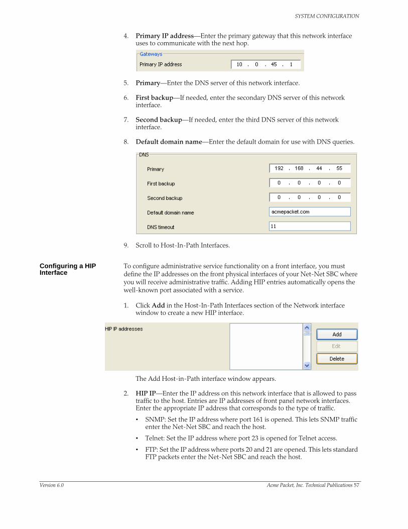
SYSTEM CONFIGURATION
4. Primary IP address—Enter the primary gateway that this network interface uses to communicate with the next hop.
5. Primary—Enter the DNS server of this network interface.
6. First backup—If needed, enter the secondary DNS server of this network interface.
7. Second backup—If needed, enter the third DNS server of this network interface.
8. Default domain name—Enter the default domain for use with DNS queries.
9. Scroll to Host-In-Path Interfaces.
Configuring a HIP Interface
To configure administrative service functionality on a front interface, you must define the IP addresses on the front physical interfaces of your Net-Net SBC where you will receive administrative traffic. Adding HIP entries automatically opens the well-known port associated with a service.
1. Click Add in the Host-In-Path Interfaces section of the Network interface window to create a new HIP interface.
The Add Host-in-Path interface window appears.
2. HIP IP—Enter the IP address on this network interface that is allowed to pass traffic to the host. Entries are IP addresses of front panel network interfaces. Enter the appropriate IP address that corresponds to the type of traffic.
• SNMP: Set the IP address where port 161 is opened. This lets SNMP traffic enter the Net-Net SBC and reach the host.
• Telnet: Set the IP address where port 23 is opened for Telnet access.
• FTP: Set the IP address where ports 20 and 21 are opened. This lets standard FTP packets enter the Net-Net SBC and reach the host.
Version 6.0 Acme Packet, Inc. Technical Publications 57

SYSTEM CONFIGURATION
• ICMP: Set the IP address to pass standard ping packets to the host.
3. Click OK to accept these HIP values.
4. Click Apply at the bottom of the network interface window to complete network interface configuration.
Enabling Management Traffic
To enable the type of traffic you want to support on the network interface:
1. FTP—Select the state of FTP.
2. ICMP—Select the state of ICMP.
3. SNMP—Select the state of SNMP.
4. Telnet—Select the state of Telnet.
5. Click Apply.
SNMP This section explains how to configure Simple Network Management Protocol (SNMP), trap receivers, and syslog servers. These features are not essential for baseline Net-Net SBC service, but they are necessary to use Acme Packet’s Net-Net EMS to manage Net-Net SBCs. They provide important monitoring and system health information that contribute to a robust deployment of the Net-Net SBC.
For detailed descriptions of the MIBs and information concerning their architecture and use, please refer to the Net-Net MIB Reference Guide.
Overview SNMP is used to support monitoring of network-attached devices for conditions that warrant administrative attention. SNMP is comprised of three groups of settings on a Net-Net SBC. These settings are system-wide configurations including MIB contact information, SNMP community settings, and trap receivers.
Basic SNMP Parameters
The Net-Net SBC includes several parameters that control basic SNMP functionality. The MIB-related elements are for informational purposes, and are
58 Net-Net 9200 EMS Configuration Guide Version 6.0

SYSTEM CONFIGURATION
helpful if set. The remainder of the parameters determines if certain Net-Net SBC events are reported to the SNMP system.
SNMP Community An SNMP community is a grouping of network devices and management stations used to define where information is sent and accepted. An SNMP device or agent might belong to more than one SNMP community. SNMP communities provide a type of password protection for viewing and setting management information within a community.
Each server that Net-Net EMS is installed on should be configured as an SNMP community on all Net-Net SBCs managed by the Net-Net EMS.
SNMP communities also include access level settings. They are used to define the access rights associated with a specific SNMP community. The Net-Net SBC lets you define two types of access levels: read-only and read-write. You can define multiple SNMP communities on a Net-Net SBC to segregate access modes per community and EMS host.
Trap Receivers A trap receiver is an application used to receive, log, and view SNMP traps for monitoring the Net-Net SBC. An SNMP trap is the notification sent from a network device, the Net-Net SBC in this case, that declares a change in service. Multiple trap receivers can be defined on a Net-Net SBC either for redundancy or to segregate alarms with different severity levels to individual trap receivers.
Each server that Net-Net EMS is installed on should be configured as a trap receiver on all Net-Net SBCs managed by Net-Net EMS.
Configuring SNMPThis section describes how to configure your Net-Net SBC to work with external SNMP systems. Sample configurations are also provided.
SNMP Configuration Overview
1. Configure the SNMP identification information. This step includes configuring the MIB system contact, name, and location parameters.
2. Set the general SNMP parameters to enable or disable SNMP on your Net-Net SBC. Also included here are switches that govern how the SNMP system responds to specified events.
3. Set SNMP communities. Their configuration is separated into a unique configuration element.
4. Set trap receivers. Their configuration is separated into a unique configuration element.
SNMP Configuration
This section describes how to configure system-wide SNMP using the Net-Net EMS.
Version 6.0 Acme Packet, Inc. Technical Publications 59

SYSTEM CONFIGURATION
1. Click the Net-Net SBC you are configuring in the Net-Net EMS navigation tree.
The SBC System window appears in the Net-Net EMS display pane.
2. Select the Management tab and General subtab.
3. System name—Enter the name of this Net-Net SBC presented within MIB transactions. This value, along with the target name of the Net-Net SBC (identified in the boot parameters) are the values reported for MIB-II when an SNMP GET is issued by the EMS for the MIB-II sysName variable. This parameter has no direct relation to the hostname parameter in the system configuration element.
By convention, this is the node’s FQDN. For SNMP MIB-II sysName GETs, the Net-Net SBC returns SNMP communications in the following format:
<targetName>[.<mib-system-name>]
target Name is the value configured in the target name (tn) boot parameter and mib-system-name is the value configured in this field.
4. System contact—Enter the contact information used with in the Net-Net SBC’s MIB transactions. The SNMP agent sends this information to an EMS in response to an SNMP Get for the MIB-II sysContact MIB variable. This parameter’s value can be a textual identification of your company’s contact person for the Net-Net SBC and/or information about how to contact that person.
5. System location—Enter the physical location of this Net-Net SBC that is reported within MIB transactions. This parameter is reported when an SNMP GET is issued by the EMS for the MIB-II sysLocation variable. This parameter has no direct relation to the location field in the system configuration element.
6. Click the Management tab.
60 Net-Net 9200 EMS Configuration Guide Version 6.0

SYSTEM CONFIGURATION
7. State—Set the SNMP system on this Net-Net SBC to enabled or disabled. By default, this parameter is set to enabled.
SNMP Community Configuration
8. Click Add in the SNMP servers section. The SNMP server dialog box appears.
9. Community name—Enter the SNMP community name of an active community where this Net-Net SBC can send or receive SNMP information. A community name value can also be used as a password to provide authentication, thereby limiting the EMSs that have access to this Net-Net SBC. With this field, the SNMP agent provides trivial authentication based on the community name that is exchanged in plain text SNMP messages.
10. IP address—Set one or multiple IP addresses that are valid within this SNMP community. These IP addresses correspond with the IP address of EMS applications that monitor or configure this Net-Net SBC, including EMS servers.
11. GET-SET—Click the checkbox to enable access mode.
12. Access mode—Select the access level from the drop-down list for all EMSs defined within this SNMP community. The access level determines the permissions that other EMS hosts can wield over this Net-Net SBC. This parameter can be set to read-only and read-write. By default, this parameter is set to read-only.
13. TRAP—Click the checkbox to enable trap receivers
14. Port—Set the IP address of an authorized EMS. This parameter is the IP address of an EMS where traps are sent. If you do not specify a port number, the default SNMP trap port of 162 will be used.
15. Filter level—Set the filter level threshold that indicates the severity level at which a trap to be sent to this particular trap receiver. Example: An alarm with a severity level of Critical is generated, the SNMP agent will only send the corresponding trap to EMSs that are configured in a trap-receiver element and have a filter-level parameter of Critical.
The following table maps Syslog and SNMP alarms to trap receiver filter levels.
Filter Level Syslog Severity Level(SNMP) Alarm Severity Level
Critical • Emergency (1)• Critical (2)
• Emergency• Critical
Major • Emergency (1)• Critical (2)• Major (3)
• Emergency• Critical• Major
Version 6.0 Acme Packet, Inc. Technical Publications 61
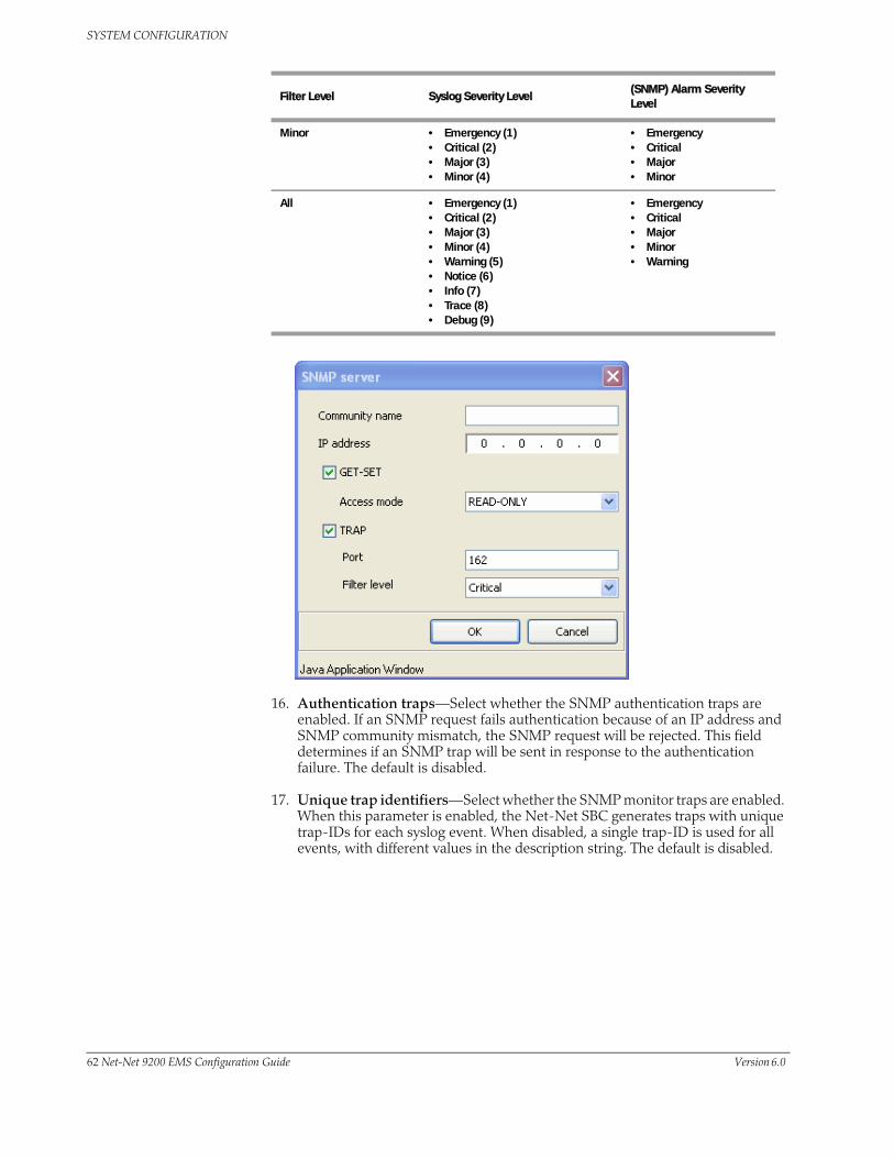
SYSTEM CONFIGURATION
16. Authentication traps—Select whether the SNMP authentication traps are enabled. If an SNMP request fails authentication because of an IP address and SNMP community mismatch, the SNMP request will be rejected. This field determines if an SNMP trap will be sent in response to the authentication failure. The default is disabled.
17. Unique trap identifiers—Select whether the SNMP monitor traps are enabled. When this parameter is enabled, the Net-Net SBC generates traps with unique trap-IDs for each syslog event. When disabled, a single trap-ID is used for all events, with different values in the description string. The default is disabled.
Minor • Emergency (1)• Critical (2)• Major (3)• Minor (4)
• Emergency• Critical• Major• Minor
All • Emergency (1)• Critical (2)• Major (3)• Minor (4)• Warning (5)• Notice (6)• Info (7)• Trace (8)• Debug (9)
• Emergency• Critical• Major• Minor• Warning
Filter Level Syslog Severity Level(SNMP) Alarm Severity Level
62 Net-Net 9200 EMS Configuration Guide Version 6.0

SYSTEM CONFIGURATION
18. Environment monitoring traps—Select whether or not the SNMP environment monitor traps are enabled. Environment traps include main board PROM temperature, CPU voltage, power supplies, fan speeds, etc.
Version 6.0 Acme Packet, Inc. Technical Publications 63

SYSTEM CONFIGURATION
Alarm ThresholdsYou can configure alarm thresholds for the following Net-Net SBC characteristics:
• CPU utilization (as a percentage of total CPU capacity)
• memory utilization (as a percentage of total memory capacity)
• license utilization (as a percentage of licensed capacity)
You can now also configure the following types of thresholds at which the Net-Net SBC sends a SNMP trap:
• critical
• major
• minor
Configuring Alarm Thresholds
You can configure alarm thresholds using Net-Net EMS.
To configure alarm thresholds:
1. Click the Net-Net SBC you are configuring in the Net-Net EMS navigation tree.
The Net-Net SBC System window appears in the Net-Net EMS display pane.
2. Click the Management tab.
3. Scroll to the Alarm threshold area.
4. Click Add. The Add Alarm threshold config dialog box appears.
5. Alarm Type—Choose the alarm threshold type from the drop-down list.
6. Severity—Choose the level of severity from the drop-down list.
64 Net-Net 9200 EMS Configuration Guide Version 6.0

SYSTEM CONFIGURATION
7. Value (%)—Enter the value at which, if exceeded, an alarm is generated. This value is expressed as a percentage ranging from 1 to 99.
8. Click OK. The dialog box closes and the name of the threshold appears in the Alarm threshold list using the following format:
alarm type:severity-value
9. Click OK.
10. Reboot the Net-Net SBC to activate the configuration.
HDR Trap for Data Push SuccessWhen you use historical data recording (HDR) on your Net-Net SBC, you can configure the system to send a trap confirming successful data pushes to designated network elements. This trap has a default level of MINOR. It contains the name of the node that successfully pushed the HDR file to an HDR server, a unique file name for the HDR file that was pushed, and the IP address of the push receiver (configured in the global collection configuration).
If you enable the trap without any configured HDR groups, the Net-Net SBC sends the trap for all HDR groups. Refer to the System Configuration chapter of the Net-Net Configuration Guide for a complete list of HDR group record types. If you configure specific groups, then the system sends the trap only for those groups.
Note: You should consider the system performance impact of enabling this trap before you do so.
Configuring HDR Data Push Success Trap
You enable the HDR data push success trap in the global collection settings, along with the sampling interval, push interval, and other settings.
To enable the HDR trap for data push success:
1. Click the Net-Net SBC you are configuring in the Net-Net EMS navigation tree.
Version 6.0 Acme Packet, Inc. Technical Publications 65
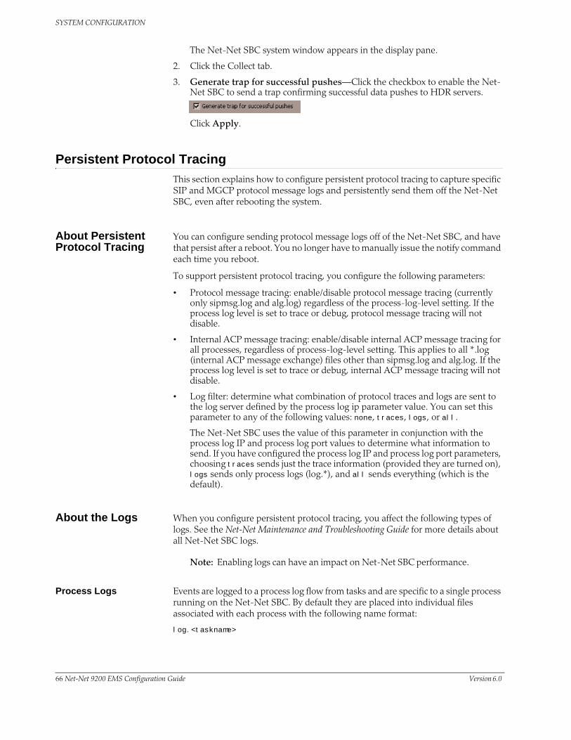
SYSTEM CONFIGURATION
The Net-Net SBC system window appears in the display pane.
2. Click the Collect tab.
3. Generate trap for successful pushes—Click the checkbox to enable the Net-Net SBC to send a trap confirming successful data pushes to HDR servers.
Click Apply.
Persistent Protocol TracingThis section explains how to configure persistent protocol tracing to capture specific SIP and MGCP protocol message logs and persistently send them off the Net-Net SBC, even after rebooting the system.
About Persistent Protocol Tracing
You can configure sending protocol message logs off of the Net-Net SBC, and have that persist after a reboot. You no longer have to manually issue the notify command each time you reboot.
To support persistent protocol tracing, you configure the following parameters:
• Protocol message tracing: enable/disable protocol message tracing (currently only sipmsg.log and alg.log) regardless of the process-log-level setting. If the process log level is set to trace or debug, protocol message tracing will not disable.
• Internal ACP message tracing: enable/disable internal ACP message tracing for all processes, regardless of process-log-level setting. This applies to all *.log (internal ACP message exchange) files other than sipmsg.log and alg.log. If the process log level is set to trace or debug, internal ACP message tracing will not disable.
• Log filter: determine what combination of protocol traces and logs are sent to the log server defined by the process log ip parameter value. You can set this parameter to any of the following values: none, traces, logs, or all.
The Net-Net SBC uses the value of this parameter in conjunction with the process log IP and process log port values to determine what information to send. If you have configured the process log IP and process log port parameters, choosing traces sends just the trace information (provided they are turned on), logs sends only process logs (log.*), and all sends everything (which is the default).
About the Logs When you configure persistent protocol tracing, you affect the following types of logs. See the Net-Net Maintenance and Troubleshooting Guide for more details about all Net-Net SBC logs.
Note: Enabling logs can have an impact on Net-Net SBC performance.
Process Logs Events are logged to a process log flow from tasks and are specific to a single process running on the Net-Net SBC. By default they are placed into individual files associated with each process with the following name format:
log.<taskname>
66 Net-Net 9200 EMS Configuration Guide Version 6.0

SYSTEM CONFIGURATION
By setting the new log-filter parameter, you can have the logs sent to a remote log server (if configured). If you set log-filter to logs or all, the logs are sent to the log server. Otherwise, the logs are still captured at the level the process-log-level parameter is set to, but the results are stored on the Net-Net SBC’s local storage.
Communication Logs These are the communication logs between processes and system management. The logs are usually named <name>.log, with <name> being the process name. For example, sipd.log. This class of log is configured by the internal trace parameter.
Protocol Trace Logs The only protocol trace logs included at this time are sipmsg.log for SIP and alg.log for MGCP. (The H.323 system tracing is not currently included.) All of the logs enabled with the call–trace parameter are sent to remote log servers, if you also set the log-filter parameter to logs or all.
Configuring Persistent Protocol Tracing
Before you configure persistent protocol tracing, ensure you have configured the process logs by setting the system configuration’s process log IP parameter. See the Net-Net Configuration Guide and the Net-Net Maintenance and Troubleshooting Guide for more information.
To configure persistent protocol tracing:
1. Click the Net-Net SBC you are configuring in the Net-Net EMS navigation tree.
The Net-Net SBC System window appears in the display pane.
2. Click the Management tab and the General sub-tab.
3. Scroll to the Protocol message tracing parameter.
4. Protocol message tracing—Choose enabled from the drop-down list to enable protocol message tracing for sipmsg.log for SIP and alg.log for MGCP.
5. Call trace mode—Set the call trace log mode you want to use. The default value is local. The valid values are:
remote—Send call trace logs to the Process log server only
local—Send call trace logs to the local file system only (default)
both—Send call trace logs to the Process log server and to the local file system
Version 6.0 Acme Packet, Inc. Technical Publications 67

SYSTEM CONFIGURATION
none—No call trace logging
6. Internal ACP message tracing—Choose enabled from the drop-down list. This enables internal ACP message tracing for all processes.
7. Log filter—Choose the log level from the drop-down list.
8. Click Apply.
68 Net-Net 9200 EMS Configuration Guide Version 6.0

SYSTEM CONFIGURATION
Syslog and Process LogsLogging events are a critical part of diagnosing misconfigurations and optimizing operations. Net-Net SBCs can send both syslog and process log data to appropriate hosts for storage and analysis.
The Net-Net SBC generates two types of log messages: syslog messages and process log messages. Syslog messages conform to the standard used for logging servers and processes as defined in RFC 3164. The contents of the Acmelog (described below) essentially contains the syslog output.
Process logs are Acme Packet proprietary logs. Process logs are generated on a per-task basis and are used mainly for debugging purposes. Because process logs are more data inclusive than syslogs, their contents usually encompass syslog log data. A special application must be run on a remote server to receive process logs.
Overview of Log Files
Syslog and process log servers are both identified by an IP address and port pair.
The Net-Net OS creates and maintains two types of log files:
• The Acmelog—This file is used to aggregate general system events that give an overview of the health and overall operating conditions of the Net-Net SBC.
• The Process Log—The process log is a file stored on a remote Acme Process Log server, on a local (to the task) core, or both. Process logs are a compendium of SBC log files, which are created by every discrete task that runs on the Net-Net SBC. The process log records as much or as little information as you require. The same data that shows up in a process log is also centrally available on the Net-Net SBC, accessible via FTP.
Process Log Messages
Process log messages are sent as UDP packets in the following format:
<file-name>:<log-message>
In this format, <filename> indicates the log filename and <log-message> indicates the full text of the log message as it would appear if it were written to the normal log file.
Syslog 1. Click the Net-Net SBC you are configuring in the Net-Net EMS navigation tree.
The SBC System window appears in the Net-Net EMS display pane.
1. Select the Management tab and General subtab.
2. Log level—Choose the syslog severity level that causes syslog traps to be sent to an EMS from the drop-down list. When this criteria is met and the
Version 6.0 Acme Packet, Inc. Technical Publications 69
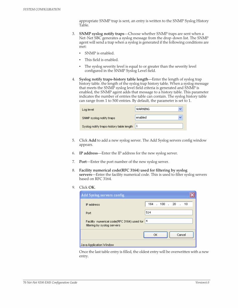
SYSTEM CONFIGURATION
appropriate SNMP trap is sent, an entry is written to the SNMP Syslog History Table.
3. SNMP syslog notify traps—Choose whether SNMP traps are sent when a Net-Net SBC generates a syslog message from the drop-down list. The SNMP agent will send a trap when a syslog is generated if the following conditions are met:
• SNMP is enabled.
• This field is enabled.
• The syslog severity level is equal to or greater than the severity level configured in the SNMP Syslog Level field.
4. Syslog notify traps-history table length—Enter the length of syslog trap history table. the length of the syslog trap history table. When a syslog message that meets the SNMP syslog level field criteria is generated and SNMP is enabled, the SNMP agent adds that message to a history table. This parameter indicates the number of entries the table can contain. The syslog history table can range from 1 to 500 entries. By default, the parameter is set to 1.
5. Click Add to add a new syslog server. The Add Syslog servers config window appears.
6. IP address—Enter the IP address for the new syslog server.
7. Port—Enter the port number of the new syslog server.
8. Facility numerical code(RFC 3164) used for filtering by syslog servers—Enter the facility numerical code. This is used to filter syslog servers based on RFC 3164.
9. Click OK.
Once the last table entry is filled, the oldest entry will be overwritten with a new entry.
70 Net-Net 9200 EMS Configuration Guide Version 6.0

SYSTEM CONFIGURATION
Global Log Level 10. Log level—Select the global log level for the system from the drop-down list in the System log level section of the screen; acmelog and syslog receive any messages that are at this level or higher. Valid values are: ZERO, EMERGENCY, CRITICAL, MAJOR, MINOR, WARNING, NOTICE, INFO. The default is WARNING.
11. Click Apply.
Configuring a Process Log Server
This section explains how to configure a process log server on your Net-Net SBC using your Net-Net EMS.
1. Log level—Select from the Log level drop-down list the starting log level that all processes running on the Net-Net SBC use. Each process running on the system has its own process log.
2. Log mode—Select the process log mode that you want to use. The available choices are:
• REMOTE—Process logs sent to the server only
• LOCAL—Process logs sent to the file only
• BOTH—Process logs sent to remote and local
• NONE—No logs are sent
3. IP address—Set the IP address of the process log server. The default value for this parameter is 0. This parameter is only configurable when REMOTE or BOTH is selected for the log mode. The field becomes disabled when either LOCAL or NONE is selected.
4. IP port—Set the port number to use for the process log server. The default value for this parameter is 0.
Task-Specific Logging This section explains how to set a log level for a specific task.
1. Click Add in the Task logging section. The Add Task logging config window appears.
Version 6.0 Acme Packet, Inc. Technical Publications 71

SYSTEM CONFIGURATION
2. Process—Select the process you are logging from the drop-down list.
3. Level—Select the log level at which the task will write event messages. If configured, this value supersedes the global RTC startup logging level, defined by the process log level parameter.
4. Mode—Enter the logging mode you want to use: remote, local, both, or none.
5. Log address—Enter the log address and port to which you are writing.
6. Click OK.
Facility Logging for Specific Tasks
You can also configure the Net-Net SBC to perform facility-specific logging for specified tasks.
A log type facility is a second filtering criteria used when writing to log files. The facility is a tag that describes the context of the event. Facility messages are filtered by the task and then by the mechanism that writes data to task log files to limit the amount of information that gets written into a task’s log file.
1. Select the task log from the Task logging config table that you want to configure facility logging for and click Edit. The Edit Task logging config window appears.
2. Click Add in the Facility logging config section of the screen. The Add Facility logging config window appears.
3. Facility—Select the facility type message you want to be logged.
4. Level—Select the log level from the drop-down list.
5. Mode—Select the mode from the drop-down list.
72 Net-Net 9200 EMS Configuration Guide Version 6.0

SYSTEM CONFIGURATION
6. Log address—Enter the remote log server address and port; your entries need to follow the IPaddress:port format.
7. Click OK.
General Management Support
The Net-Net SBC supports the following general management parameters.
1. Log files compression—Click the checkbox to enable log file compression.
2. Reset card if a task failure is detected—Click the checkbox to if you want the Net-Net SBC to reboot a card if a task failure is detected. This is for debugging purposes only.
3. Health monitor of transcode path—Click the checkbox if you want the Net-Net SBC to monitor the health of the xcode path.
4. Route outgoing HIP packet to source interface—Click the checkbox if you want the Net-Net SBC to route outgoing HIP packets to the interface associated with the source IP address. .
5. Click Apply.
Version 6.0 Acme Packet, Inc. Technical Publications 73

SYSTEM CONFIGURATION
Host RoutesThis section explains how to configure host route exceptions on the Net-Net SBC.
Overview Host routes let you insert entries into the Net-Net SBC's routing table. These routes affect traffic that originates at the Net-Net SBC’s host process. Host routes are used primarily for steering management traffic to the correct network.
When traffic is destined for a network that is not explicitly defined on a Net-Net SBC, the default gateway (located in the system config) is used. If you try to route traffic to a specific destination that is not accessible through the default gateway, you need to add a host route. Host routes can be thought of as a default gateway override.
Configuring Host Routes
This section describes how to configure host routes.
1. Click the Net-Net SBC you are configuring in the Net-Net EMS navigation tree.
The SBC System window appears in the Net-Net EMS display pane.
2. In the Host routes table, click Add.
The Add Host route window appears.
3. IP address—Enter the IP address of the destination network that this host route points toward.
4. Subnet mask—Enter the netmask portion of the destination network for the route you are creating.
74 Net-Net 9200 EMS Configuration Guide Version 6.0

SYSTEM CONFIGURATION
5. Gateway IP address to destination network—Enter the IP address of the gateway that traffic destined for the address defined in the first two elements should use as its first hop.
6. Click OK to continue.
7. Click Apply to complete configuring host routes.
AccountingThis section explains SIP accounting using the Remote Authentication Dial In User Service (RADIUS) Accounting System (RAS).
The Net-Net SBC uses the RADIUS protocol to send accounting messages. These messages are transmitted to one of a predefined list of accounting servers using a predefined forwarding strategy. RAS provides a mechanism for temporarily storing session initiation and completion statistics, and for delivering these statistics to accounting servers located elsewhere in the network.
SIP Session Accounting
The RAS client can record SIP session activity based on configuration and a CDR. The CDR determines which messages are generated and determines the RADIUS attributes included in the messages. The RAS client must be capable of sending CDRs to any number of RADIUS accounting servers, using the defined hunt, failover, round robin, fewest pending, or fastest server strategies.
The establishment, failed establishment, change, or removal of a SIP session can trigger RADIUS Accounting Request messages. The RAS might also send notification of its status (enabled/disabled). RADIUS Accounting Request messages include the following:
• Start—SIP session has started.
• Interim-Update—SIP session parameters have changed.
• Stop—SIP session has ended.
• Accounting-On—Creation of a new RADIUS client.
• Accounting-Off—RADIUS client has shut down.
Each SIP session might generate Start, Interim-Update, and Stop messages based on the local configuration when the session is initiated. Each Start message tells the RADIUS server that a SIP session has started. Each Interim-Update message changes the SIP session parameters, and may report the session characteristics for the SIP session to that point. Each Stop message informs the RADIUS server that a SIP session has ended and reports session characteristics.
Version 6.0 Acme Packet, Inc. Technical Publications 75

SYSTEM CONFIGURATION
The RAS can transmit all RADIUS messages related to a SIP session at the end of the session, regardless of which messages are generated and when they are generated. You might choose this option to reduce the likelihood of the RADIUS messages being logged to different servers, or in different log files on the same server.
The RAS always generates a RADIUS Stop message when the SIP session ends, regardless of the SIP session termination cause. The termination cause and the session characteristics are reported.
Accounting Configuration
1. Click the Net-Net SBC you are configuring in the Net-Net EMS navigation tree.
The SBC System window appears in the Net-Net EMS display pane.
2. Click the Accounting tab.
3. State—Select enabled from the drop-down list to activate accounting on the system.
4. Host name—Enter a host name. For this parameter, the default is localhost and this value must remain in order for the accounting configuration to work properly.
5. Port—Enter the number of the UDP port associated with the Net-Net SBC from which RADIUS messages are sent. The default is 1813.
• Minimum—1025
• Maximum—65535
6. Start—Select the event that causes a RADIUS Start record to be generated.
• Set None so that Start records will not be generated
• Set INVITE so that Start records will be generated on receipt of the INVITE
• Set OK so that Start records will be generated on receipt of the OK.
76 Net-Net 9200 EMS Configuration Guide Version 6.0

SYSTEM CONFIGURATION
7. Click Add in the messages section of the screen to add interim events. The Add Interim dialog box appears.
8. Event—Select the interim event you want to add from the drop-down list. The valid events are: OK, REINVITE, REINVITE-RESPONSE, and REINVITE-CANCEL.
9. Click OK.
The event you select appears in the Interim table. You can select multiple events by repeating steps 7-9.
10. Transmission timing—Select the Transmission timing behavior you want.
• each message—Net-Net SBC transmits each CDR as soon as the corresponding signaling message is processed.
• session end—Net-Net SBC transmits accounting information at the close of a session.
11. Max time-message retransmit (secs)—Indicate the length of time in seconds that you want the Net-Net SBC to continue trying to send each accounting message. During this delay, the Net-Net SBC can hold a generic queue of 4096 messages. The default is 60.
• Minimum—0
• Maximum—999999999
12. Max. message queue before failover (#)—Set the maximum number of accounting messages the Net-Net SBC can store its message waiting queue for a specific accounting server before it is considered a failover. The default is 100.
Once this value is exceeded, the Net-Net SBC attempts to send its accounting messages—including its pending messages—to the next accounting server in its configured list.
• Minimum—1 message
• Maximum—4096 messages
Version 6.0 Acme Packet, Inc. Technical Publications 77

SYSTEM CONFIGURATION
13. Multiple server usage strategy—Select the strategy you want used to select the accounting servers to which the Net-Net SBC will send its accounting messages. The following table lists the available strategies.
Accounting Server You must establish the list of servers to which the Net-Net SBC can send accounting messages.
1. Click the Net-Net SBC you are configuring in the Net-Net EMS navigation tree.
The SBC System window appears in the Net-Net EMS display pane.
2. Click the Accounting tab.
Strategy Description
hunt Selects accounting servers in the order in which they are listed.If the first accounting server is online, working, and has not exceeded any of the defined constraints, all traffic is sent to it. Otherwise the second accounting server is selected. If the first and second accounting servers are offline or exceed any defined constraints, the third accounting server is selected. And so on through the entire list of configured servers
failover Uses the first server in the list of predefined accounting servers until a failure is received from that server. Once a failure is received, it moves to the second accounting server in the list until a failure is received. And so on through the entire list of configured servers.
round robin Selects each accounting server in order, distributing the selection of each accounting server evenly over time.
fastest round trip time Selects the accounting server that has the fastest round trip time (RTT) observed during transactions with the servers (sending a record and receiving an ACK).
fewest pending Selects the accounting server that has the fewest number of unacknowledged accounting messages (that are in transit to the Net-Net SBC).
78 Net-Net 9200 EMS Configuration Guide Version 6.0

SYSTEM CONFIGURATION
3. Click Add in the RADIUS accounting servers portion of the screen. The Add Accounting server window appears.
4. Host name or IP address—Enter the name of the host associated with the accounting server in hostname format (FQDN) or as an IP address.
5. IP port—Enter the number of the UDP port associated with the accounting server to which RADIUS messages are sent. The default is 1813.
• Minimum—1025
• Maximum—65535
6. State—Select whether the accounting servers on the system are enabled or disabled.
7. Min. round trip time threshold (ms)—Enter the minimum round trip time of an accounting message. The default is 250 milliseconds.
• Minimum—10 milliseconds
• Maximum—5000 milliseconds
A round trip consists of the following:
– The Net-Net SBC sends an accounting message to the accounting server.
– The accounting server processes this message and responds back to the Net-Net SBC.
If the fastest RTT is the strategy for the accounting configuration, the value you enter here can be used to determine an order of preference (if all the configured accounting servers are responding in less than their minimum RTT).
8. VSA bundling—Retain the default enabled if you want the accounting server to bundle the VSAs within RADIUS accounting messages. Enter disabled if you do not want the VSAs to be bundled. (Bundling means including multiple VSAs within the vendor value portion of the message.)
In a bundled accounting message, the RADIUS message type is vendor-specific, the length is determined for each individual message, and the vendor portion begins with a 4-byte identifier, and includes multiple vendor type, vendor length, and vendor value attributes.
9. Maxtime ACK (sec)—Enter the length of time in seconds that you want the Net-Net SBC with pending accounting messages to wait when it has not received a valid response from the target accounting server.
• Minimum—1 second
• Maximum—300 seconds
Once this timer value is exceeded, the Net-Net SBC marks the unresponsive accounting server as disabled in its failover scheme. When a server connection is marked as inactive, the Net-Net SBC attempts to restart the connection and transfers pending messages to another queue for transmission. RADIUS messages might be moved between different accounting servers as servers become inactive or disabled.
10. Min. time-reinstate delay (sec)—Enter the length of time in seconds you want the Net-Net SBC to wait before resending messages to a disabled accounting server. The default is 30.
• Minimum—1 second
Version 6.0 Acme Packet, Inc. Technical Publications 79

SYSTEM CONFIGURATION
• Maximum—300 seconds
11. Shared secret—Enter the secret passed from the accounting server to the client in text format. Transactions between the client and the RADIUS server are authenticated by the shared secret; which is determined by the source IP address of the received packet.
12. NAS ID—Optional. Enter the NAS ID in text format (FQDN allowed). The accounting server uses this value to identify the Net-Net SBC for the transmittal of accounting messages.
The remote server to which the accounting configuration sends messages uses at least one of two potential pieces of information for purposes of identification. The Net-Net SBC accounting messages always includes in the first of these:
• Network Access Server (NAS) IP address (the IP address of the Net-Net SBC’s SIP proxy)
• NAS ID (the second piece of information) provided by this value. If you enter a value here, the NAS ID is sent to the remote server.
• NAS ID (the second piece of information) provided by this value. If you enter a value here, the NAS ID is sent to the remote server.
If you have more than one Net-Net SBC pointing to the same accounting server, the NAS ID can be used to identify which Net-Net SBC generated the record.
13. Click OK.
80 Net-Net 9200 EMS Configuration Guide Version 6.0

SYSTEM CONFIGURATION
Packet TracePacket tracing lets the Net-Net SBC mirror any communication between two endpoints, or between itself and a specific endpoint. To accomplish this, the Net-Net SBC replicates the packets sent and received, and then sends them to a trace server that you designate. Using the trace server, you can display the packets on software protocol analyzer. Currently, the Net-Net SBC supports:
• One configurable trace server (on which you have installed your software protocol analyzer)
• Sixteen concurrent endpoint traces
Note: The information included here describes how packet tracing works. It also contains the information you need to use Net-Net EMS to configure packet tracing and to use the Acme Command Line Interface (ACLI) to start and stop packet tracing.
How It Works You configure a trace server on the Net-Net SBC so that it knows where to send the mirrored packets. Then the Net-Net SBC bases the trace on one of its internally configured IP addresses (such as one for a SIP interface or for an H.323 interface).
Note: Set up the capture filter “ip proto 4” in your software protocol analyzer if you only want to see the results of the Net-Net SBC packet trace(s).
Once the trace is initiated, the Net-Net SBC duplicates all packets sent to and from the endpoint identified by the IP address that are sent or received on the specified Net-Net SBC network interface.
The Net-Net SBC then encapsulates the original packets in accordance with RFC 2003 (IP Encapsulation within IP); it adds the requisite headers, and the payload contains the original packet trace with the Layer 2 header removed. Because software protocol analyzers understand RFC 2003, they can easily parse the original traced packets. In order to see only packet traces information in your software protocol analyzer, you can use the capture filter “ip proto 4.”
It is possible that—for large frames—when the Net-Net SBC performs the steps to comply with RFC 2003 by adding the requisite header, the resulting packet might exceed Ethernet maximum transmission unit (MTU). This could result in packets being dropped by external network devices, but widespread support for jumbo frames should mitigate this possibility.
If the Net-Net SBC either receives or transmits IP fragments during a packet trace, then it will only trace the first fragment. The first fragment is likely to be a maximum-sized Ethernet frame.
The Net-Net SBC continues to conduct the packet trace and send the replicated information to the trace server until you instruct it to stop. You stop a packet trace with the ACLI packet-trace stop command. With this command, you can stop either an individual packet trace or all packet traces that the Net-Net SBC is currently conducting.
Version 6.0 Acme Packet, Inc. Technical Publications 81

SYSTEM CONFIGURATION
The following illustration shows the packet trace process.
Packet Trace Scenarios
This section describes three possible ways that you might use the packet trace feature. You can examine communications sent to and from one endpoint, sent between two endpoints, or sent between ingress and/or egress Net-Net SBC interfaces to endpoints.
Packet Trace for One Endpoint
When you use the packet-trace-state command, the Net-Net SBC sets up packet tracing for one endpoint. The Net-Net SBC collects and replicates the packets to and from one endpoint. To enable this kind of trace, you set up one packet trace using the packet-trace-start command.
The commands you carry out would take the following form:
ACMEPACKET# packet-trace-start F01 <IP address of Endpoint A>
82 Net-Net 9200 EMS Configuration Guide Version 6.0

SYSTEM CONFIGURATION
Packet Trace for Both Call Legs
If you want to trace both sides (both call legs), then you must set up individual traces for each endpoint—meaning that you would initiate two packet traces. The results of the trace will give you the communications both call legs for the communication exchanged between the endpoints you specify.
If you initiate a packet trace for both endpoints that captures both signaling and media, the signaling will be captured as usual. However, RTP will only be captured for the ingress call leg. This is because the Net-Net SBC performs NAT on the RTP, which means it cannot be captured on the egress call leg.
The commands you carry out would take the following form:
ACMEPACKET# packet-trace-start F01 <IP address of Endpoint A>
ACMEPACKET# packet-trace-start F02 <IP address of Endpoint B>
Packet Trace for a Net-Net SBC Signaling Address
You can perform a packet trace for addresses internal to the Net-Net SBC; this can be the address, for example, of a SIP or an H.323 interface. Using signaling interface addresses puts the emphasis on the Net-Net SBC rather than on the endpoints by allowing you to view traffic from specified interfaces.
The commands you carry out would take the following form:
ACMEPACKET# packet-trace-start F01 <IP address of Net-Net 9000 interface1>
ACMEPACKET# packet-trace-start F02 <IP address of Net-Net 9000 interface2>
Version 6.0 Acme Packet, Inc. Technical Publications 83

SYSTEM CONFIGURATION
Configuring Packet TracingTo configure packet tracing, you need to configure the Net-Net SBC with the trace server information so that the Net-Net SBC knows where to send replicated data. The Net-Net SBC supports one trace server.
To configure a trace server on your Net-Net SBC:
1. Click the Net-Net SBC you are configuring in the Net-Net EMS navigation tree.
The Net-Net SBC system window appears in the display pane.
2. Click the Management tab and the Packet trace sub-tab.
If Net-Net EMS did not find a capture receiver configuration during the discovery process, it flags the configuration screen with the following label:
This object is not configured
For example:
84 Net-Net 9200 EMS Configuration Guide Version 6.0
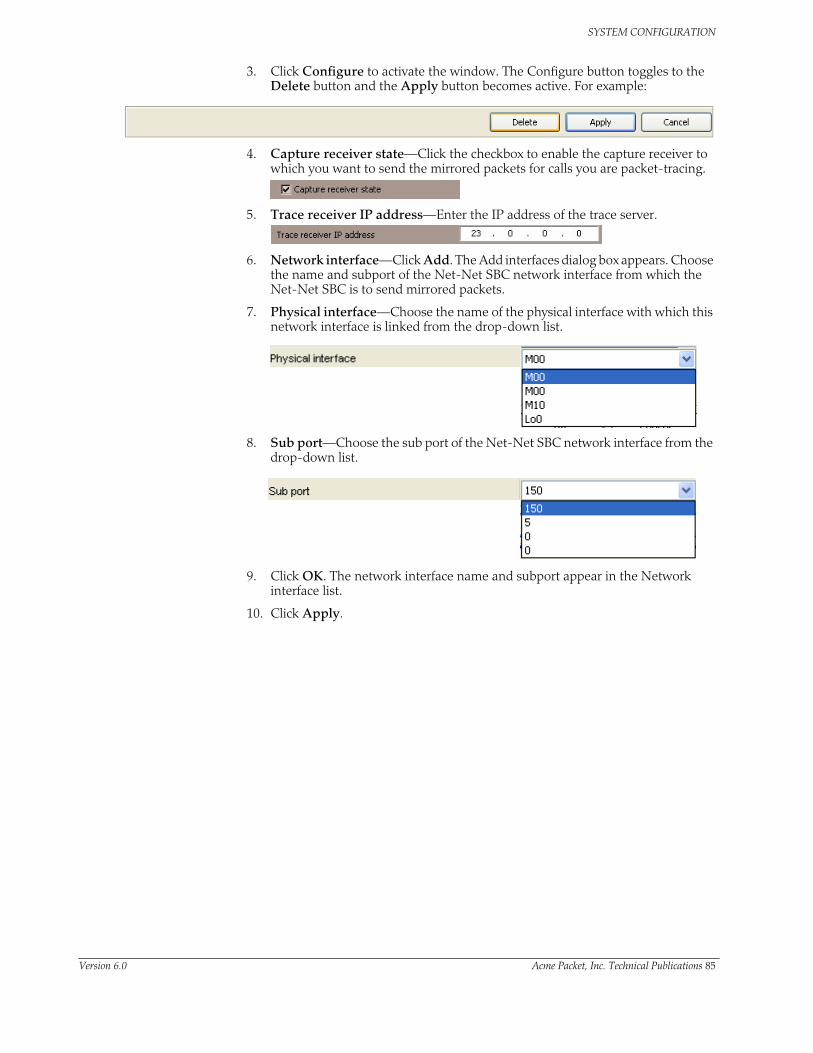
SYSTEM CONFIGURATION
3. Click Configure to activate the window. The Configure button toggles to the Delete button and the Apply button becomes active. For example:
4. Capture receiver state—Click the checkbox to enable the capture receiver to which you want to send the mirrored packets for calls you are packet-tracing.
5. Trace receiver IP address—Enter the IP address of the trace server.
6. Network interface—Click Add. The Add interfaces dialog box appears. Choose the name and subport of the Net-Net SBC network interface from which the Net-Net SBC is to send mirrored packets.
7. Physical interface—Choose the name of the physical interface with which this network interface is linked from the drop-down list.
8. Sub port—Choose the sub port of the Net-Net SBC network interface from the drop-down list.
9. Click OK. The network interface name and subport appear in the Network interface list.
10. Click Apply.
Version 6.0 Acme Packet, Inc. Technical Publications 85

SYSTEM CONFIGURATION
System ACLsYou can configure a system access control list (ACL) for your Net-Net SBC that determines what traffic the Net-Net SBC allows over its management interface (wancom0). By specifying who has access to the Net-Net SBC via the management interface, you can provide DoS protection (not policing) for this interface.
Using a list of IP addresses and subnets that are allowable as packet sources, you can configure what traffic the Net-Net BG accepts and what it denies. All IP packets arriving on the management interface are subject to these rules; if it does not match your configuration for system ACL, then the Net-Net SBC drops it.
Note, however, that all IP addresses configured in the SNMP community table are automatically permitted.
Configuring System ACLs
For each entry, you must define an IP source address and mask; you can specify either the individual source host or a unique source subnet.
If you do not configure this list, then there will be no ACL/DoS protection for the Net-Net BG’s management interface.
Adding an ACL for the Management Interface
To add an ACL for the management interface:
1. Click the Net-Net SBC you are configuring in the Net-Net EMS navigation tree.
The Net-Net SBC system window appears in the Net-Net EMS display pane.
2. Click the SBC System tab.
3. For the Management interface access list, click Add. The Add Management interface access list dialog box appears.
4. IP address—Enter the IP address representing for the source network for which you want to allow traffic over the management interface.
5. Subnet mask—Enter the netmask portion of the source network for the traffic you want to allow
86 Net-Net 9200 EMS Configuration Guide Version 6.0

SYSTEM CONFIGURATION
6. Click OK. The IP address and subnet mask appear in the Management interface access list.
7. Repeat steps 3 through 6 to add more IP addresses and subnet masks you want to allow as packet sources.
8. Click Apply.
Version 6.0 Acme Packet, Inc. Technical Publications 87

SYSTEM CONFIGURATION
88 Net-Net 9200 EMS Configuration Guide Version 6.0

5 Realms and Nested Realms
IntroductionThis chapter explains how to configure realms and nested realms.
A realm is a logical definition of a network or groups of networks made up in part by devices that provide real-time communication sessions comprised of signaling messages and possibly media flows. These network devices might be call agents, softswitches, SIP proxies, IP PBXs, etc., that are statically defined by IP addresses. These network devices might also be IP endpoints: SIP phones, IADs, MAs, media gateways, etc., that are defined by an IP address prefix.
Realms support bandwidth-based call admission control and QoS marking for media. They are the basis for defining egress and ingress traffic to the Net-Net SBC—which supports the Net-Net SBC’s topology hiding capabilities.
This chapter also explains how to configure media ports (steering pools). A steering pool exists within a realm and contains a range of ports that have a common address (for example, a target IP address). The range of ports contained in the steering pool are used to steer media flows from one realm, through the Net-Net SBC, to another.
Finally, in this chapter you can learn about TOS/DiffServ functionality for realm-based packet marking by media type.
Overview Realms are a logical distinction representing routes (or groups of routes) reachable by the Net-Net SBC and what kinds of resources and special functions apply to those routes. Realms are used as a basis for determining ingress and egress associations to network interfaces, which can reside in different VPNs. The ingress realm is determined by the signaling interface on which traffic arrives. The egress realm is determined by the following:
• Routing policy—Where the egress realm is determined in the session agent configuration or external address of a SIP-NAT
• Realm-bridging—As applied in the SIP-NAT configuration
• Third-party routing/redirect (i.e., SIP redirect)
Version 6.0 Acme Packet, Inc. Technical Publications 77

REALMS AND NESTED REALMS
Realms also provide configuration support for denial of service (DoS)/access control list (ACL) functionality. For more information about the Net-Net SBC’s DoS/ACL capabilities and configuration, refer to this guide’s Security chapter.
Realms can also be nested in order to form nested realm groups. Nested realms consist of separate realms that are arranged within a hierarchy to support network architectures that have separate backbone networks and VPNs for signaling and media. This chapter provides detailed information about nested realms after showing you how to configure realms on your Net-Net EMS.
About Realms and Network Interfaces
All realms reference network interfaces on the Net-Net SBC. This reference is made when you configure a list of network interfaces in the realm configuration.
You configure a network interface to specify logical network interfaces that correspond existing physical interfaces on the Net-Net SBC. Configuring multiple network interfaces on a single physical interface creates a channelized physical interface, a VLAN. VLANs, in turn, allow you to reuse address space, segment traffic, and maximize bandwidth.
In order to reach the realms you configure, you need to assign them network interfaces. The values you set for the name and port in the network interface you select then indicate where the realm can be reached.
About the SIP Home Realm
The realm configuration is also used to establish what is referred to as the SIP home realm. This is the realm where the Net-Net SBC’s SIP proxy sits.
In peering configurations, the SIP home realm is the internal network of the SIP proxy. In backbone access configurations, the SIP home realm typically interfaces with the backbone connected network. In additions, the SIP home realm is usually exposed to the Internet in an HNT configuration.
Although you configure a SIP home realm in the realm configuration, it is specified as the home realm in the main SIP configuration by the home realm identifier parameter. Specifying the SIP home realm means that the Net-Net SBC’s SIP proxy can be addressed directly by connected entities, but other connected network signaling receives layer 3 NAT treatment before reaching the internal SIP proxy.
For more information about SIP functionality and features, refer to this guide’s SIP Configuration chapter.
About Realms and Other Net-Net SBC Functions
Realms are referenced by other configurations in order to support this functionality across the protocols the Net-Net SBC supports and to make routing decisions. Other configurations’ parameters that point to realms are:
• SIP configuration: home realm identifier, egress realm identifier
• SIP-NAT configuration: realm identifier
• Session agent configuration: realm identifier
• Media manager: home realm identifier
• Steering ports: realm identifier
• Static flow: in realm identifier, out realm identifier
78 Net-Net 9200 EMS Configuration Guide Version 6.0

REALMS AND NESTED REALMS
Configuration OverviewRealm configuration is divided into the following functional areas, and the steps for configuring each are set out in this chapter: identity and IP address prefix, realm interfaces, realm service profiles, QoS measurement, QoS marking, address translation profiles, and DNS server configuration.
Before You Configure
Before you configure realms, you want to establish the physical and network interfaces with which the realm will be associated.
• Configure a physical interface to define the physical characteristics of the signaling line.
• Configure a network interface to define the network in which this realm is participating and optionally to create VLANs.
If you want to use QoS, you should also determine if your Net-Net SBC is QoS enabled. Remember that you will also use this realm in other configurations to accomplish the following:
• Set a signaling port or ports at which the Net-Net SBC listens for signaling messages.
• Configure sessions agents to point to ingress and egress signaling devices located in this realm in order to apply constraint for admission control.
• Configure session agents for defining trusted sources for accepting signaling messages.
Configuration Overview
This section contains a configuration overview:
• Identity and IP address prefix— Configure a realm name (a unique identifier) and an IP address prefix and subnet mask.
The IP address and subnet mask establish a set of matching criteria for the realm, and distinguishes between realms that you assign to the same network interface.
• Realm interfaces—The realm points to one or more network interfaces on the Net-Net SBC. For more information, refer to this chapter’s About Realms and Network Interfaces section. For information about configuring network interfaces and VLAN support, refer to this guide’s System Configuration chapter.
• Realm service profile—The parameters you configure to establish the realm service profile determine how bandwidth resources are used and how media is treated in relation to the realm. Bandwidth constraints set for realm service profiles support the Net-Net SBC’s admission control feature. For further information about this feature, refer to this guide’s Admission Control and QoS chapter.
Peer-to-peer media between endpoints can be treated in one of three different ways:
• Media can be directed between sources and destinations within this realm on this specific Net-Net SBC. Media travels through the Net-Net SBC rather than straight between the endpoints.
• Media can be directed through the Net-Net SBC between endpoints that are in different realms, but share the same subnet.
• For SIP only, media can be released between multiple Net-Net SBCs.
Version 6.0 Acme Packet, Inc. Technical Publications 79

REALMS AND NESTED REALMS
To enable SIP distributed media release, you must set the appropriate parameter in the realm configuration. You must also set the SIP options parameter to media-release with the appropriate header name and header parameter information. This option defines how the Net-Net SBC encodes IP address and port information for media streams described by, for example, SDP.
• QoS measurement—Refer to this guide’s Admission Control and QoS chapter for more information about enabling QoS measurements on your Net-Net SBC. This chapter provides detailed information about when to configure the qos-enable parameter. If you are not using QoS or a QoS-capable Net-Net SBC, then you can leave this parameter set to disabled (default).
• QoS marking—QoS marking allows you to apply a set of TOS/DiffServ mechanisms that enable you to provide better service for selected networks.
You can configure a realm to perform realm-based packet marking by media type, either audio/voice or video.
The realm configuration references a set of media policies that you configure in the media policy configuration. Within these policies, you can establish TOS/DiffServ values that define an individual type (or class) of service, and then apply them on a per-realm basis. In the media profiles, you can also specify:
• One or more audio media types for SIP
• One or more video types for SIP
• Both audio and video media types for SIP
• Address translation profiles—Refer to this guide’s Number Translations chapter for realm-specific information about using address translations on your Net-Net SBC. If you are not using this feature, you can leave the in-translationid and out-translationid parameters blank.
• DNS servers—You can configure DNS functionality on a per-network-interface basis, or you can configure DNS servers to use per realm. Configuring DNS servers for your realms means that you can have multiple DNS servers in connected networks. In addition, this allows you to specify which DNS server to use for a given realm such that the DNS might actually be in a different realm with a different network interface.
This feature is available for SIP only.
• DoS/ACL configuration—Refer to this guide’s Security chapter for realm-specific information about using DoS/ACL functionality on your Net-Net SBC. If you are not using this functionality, you can leave the parameters at their default values.
• Admission control configuration—You can set admission control based on bandwidth for each realm by setting the max-bandwidth parameter for the realm configuration. Details about admission control are covered in this guide’s Admission Control and QoS chapter.
80 Net-Net 9200 EMS Configuration Guide Version 6.0

REALMS AND NESTED REALMS
Configuration Timestamp
You might see the following information on some of the configuration windows:
This is a configuration timestamp that displays last modified information for configuration changes made using Net-Net EMS.
When you make configuration changes to elements, the Last modified by field displays the following information:
• Net-Net EMS identifier
• Name of the user that made the modification
• IP address of the host machine upon which Net-Net EMS is running
• Relevant time zone information to specify how to interpret the timestamp in the Last modified date field.
For example:
EMS_admin_172.30.80.2_UTC
The Last modified date is displayed in the string date/time format, YYYY-MM-DD HH:MM:SS. For example 2007-11-07 15:16:05. When you make configuration changes using the Net-Net EMS, the date timestamp is specified in UTC.
If a sub-element is modified the timestamp belonging to the element is updated to indicate the modification time.
Configuring RealmsThis section describes how to configure realms on your Net-Net SBC from the Net-Net EMS.
Creating the Realm To create a realm:
1. Click Realms in the Net-Net EMS navigation tree.
The Realm window appears in the display pane.
2. Click Add. The Add Realm window appears.
3. Name—Enter the name of the new realm you creating and click OK to continue.
Version 6.0 Acme Packet, Inc. Technical Publications 81
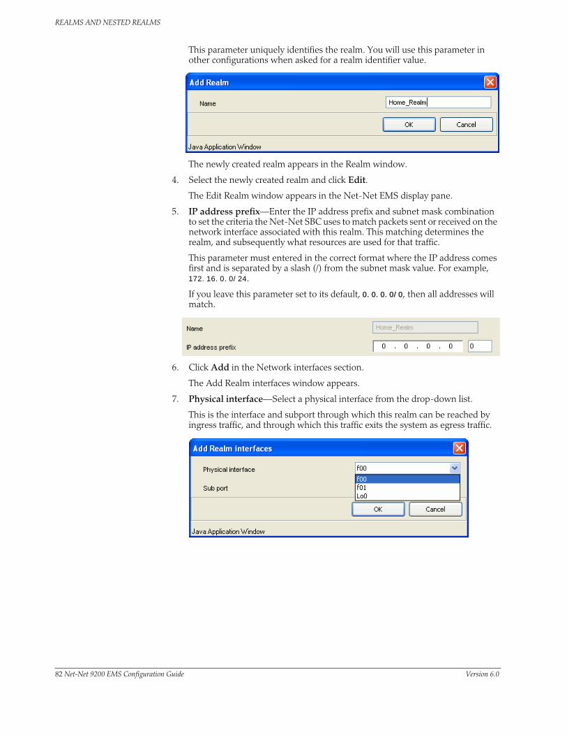
REALMS AND NESTED REALMS
This parameter uniquely identifies the realm. You will use this parameter in other configurations when asked for a realm identifier value.
The newly created realm appears in the Realm window.
4. Select the newly created realm and click Edit.
The Edit Realm window appears in the Net-Net EMS display pane.
5. IP address prefix—Enter the IP address prefix and subnet mask combination to set the criteria the Net-Net SBC uses to match packets sent or received on the network interface associated with this realm. This matching determines the realm, and subsequently what resources are used for that traffic.
This parameter must entered in the correct format where the IP address comes first and is separated by a slash (/) from the subnet mask value. For example, 172.16.0.0/24.
If you leave this parameter set to its default, 0.0.0.0/0, then all addresses will match.
6. Click Add in the Network interfaces section.
The Add Realm interfaces window appears.
7. Physical interface—Select a physical interface from the drop-down list.
This is the interface and subport through which this realm can be reached by ingress traffic, and through which this traffic exits the system as egress traffic.
82 Net-Net 9200 EMS Configuration Guide Version 6.0

REALMS AND NESTED REALMS
8. Sub port—Select the VLAN identifier for the network interface to which you are assigning this realm
9. Click OK to continue.
Configuring the Realm
To configure the realm:
1. Click the Realm tab of the Edit realm window.
2. Session admission control—Click the checkbox to enable session admission control.
3. Bandwidth limit (kilobits per second)—Set the maximum bandwidth resources available for this realm; the default is 0.
4. Within this realm serviced by this Net-Net system only—Click the checkbox to set the behavior of media steering when endpoints within the same realm are communicating.
5. Within different realms in same subnet serviced by this Net-Net system only—Click the checkbox to set the behavior of media steering when endpoints located in different realms, but that are connected to the same network interface, are communicating.
6. Within this realm serviced by different Net-Net systems (SIP only)—Click the checkbox to include multi-system release information in SIP requests sent to this realm.
7. QoS measurements—Click the checkbox to enable QoS capability.
8. Profile name—Select the name (unique identifier) of the media policy you want to apply in the realm from the Profile name drop-down list. If you leave this
Version 6.0 Acme Packet, Inc. Technical Publications 83

REALMS AND NESTED REALMS
parameter empty, then QoS marking for media will not be performed for this realm.
9. Use DNS Server in this realm—Select the realm whose network interface’s DNS server should be used to resolve this realm’s FQDN lookup.
If you do not configure this parameter, then the realm will use the DNS information configured in its associated network interface.
10. Click Apply.
Nested RealmsConfiguring nested realms allows you to create backbone VPN separation for signaling and media. This means that you can put signaling and media on separate network interfaces, that the signaling and media VPN can have different address spaces, and that the parent realm has one media-only sub-realm.
The following figure shows the network architecture.
84 Net-Net 9200 EMS Configuration Guide Version 6.0

REALMS AND NESTED REALMS
In addition, you can achieve enhanced scalability by using a shared service interface. A single service address is shared across many customers/peers, customer specific policies for bandwidth use and access control are preserved, and you can achieve fine-grained policy control.
These benefits are achieved when you configure these types of realms:
• Realm group—A hierarchical nesting of realms identified by the name of the highest order realm.
• Controlling realm—A realms for which a signaling interface is configured. For example, you might configure these signaling interfaces in the following configurations: SIP-NAT, or SIP port. Typically, this is the highest order realm for the parent realm in a realm group.
• Parent realm—A realm that has one or more child realms. A parent realm might also be the child realm of another realm group.
• Child realm—A realm that is associated with a single higher order parent realm. A child might also be the parent realm of another realm group. Child realms inherit all signaling and steering ports from higher order realms.
• Media-only realm—A realm for which there is no configured signaling interface directly associated. Media-only realms are nested within higher order realms.
Version 6.0 Acme Packet, Inc. Technical Publications 85

REALMS AND NESTED REALMS
As these definitions suggest, parent and child realms can be constructed so that there are multiple nesting levels. Lower order realms inherit the traits of the realms above them, including: signaling service interfaces, session translation tables, and steering pools.
Since realms inherit the traits of the realms above them in the hierarchy, you will probably want to map what realms should be parents and children before you start configuring them. These relationships are constructed through one parameter in the realm configuration that identifies the parent realm for the configuration. If you specify a parent realm, then the realm you are configuring becomes a child realm subject to the configured parameters you have established for that parent. And since parent realms can themselves be children of other realm, it is important that you construct these relationships with care.
Configuring Nested Realms
When you are configuring nested realms, you can separate signaling and media by setting realm parameters in the SIP interface configuration and the steering ports configuration.
• The realm identifier you set in the SIP interface configuration labels the associated realm for signaling.
• The realm identifier you set in the steering ports configuration labels the associated realm for media.
Constructing a hierarchy of nested realms requires that you note which realms you want to handle signaling, and which you want to handle media.
In the SIP port configuration for the SIP interface configuration, you will find an allow anonymous parameter that allows you to set certain access control measures.
Configuring Nested Realms
This section describes how to configure nested realms on your Net-Net SBC from the Net-Net EMS, and provides instructions for signaling applications where you are using nested realms.
PAR E N T R E ALM ABCD
SIG N ALIN G IN TE R F ACE MAX BAN DWIDTH STE ER IN G PO R TS
SUB-R EALM A B SUB-R E ALM C D
ME DIA/BWO N LY
MED IA/BWO N LYMAX BW MAX BW
STE ER IN GPO R TS
STE E R IN GPO R TS
SUB-R E ALM A SUB-R EALM CSUB-R E ALM B SUB-R EALM D
ME DIA/BW
O N LY
MAXBW
STE ERIN G
PO R TS
MEDIA/BWO N LY
ME DIA/BWO N LY
ME DIA/BWO N LY
MAXBW
MAXBW
MAXBW
STE ERIN G
PO O L
STEE R ING
PO R TS
STE E R ING
PO R TS
86 Net-Net 9200 EMS Configuration Guide Version 6.0

REALMS AND NESTED REALMS
Choosing the Parent Realm
1. Click Realms in the Net-Net EMS navigation tree.
The Realm window appears in the display pane.
2. Select the newly created realm and click Edit.
The Edit Realm window appears in the Net-Net EMS display pane.
3. Realm group—Choose the realm that will be the parent of this realm from the Realm group drop-down list.
Configuring this parameter makes the realm you are currently configuring the child of the parent you name. As such, the child realm is subject to the configured parameters for the parent.
4. Click Apply.
Realm-Based Packet MarkingThe Net-Net SBC supports TOS/DiffServ functions that allow you to
• Set up realm-based packet marking by media type, either audio-voice or video
• Set up realm-based packet marking for signaling SIP
Upstream devices use these markings to classify traffic in order to determine the priority level of treatment it will receive.
About TOS/DiffServ
TOS and DiffServ are two different mechanisms used to achieve QoS in enterprise and service provider networks; they are two different ways of marking traffic to indicate its priority to upstream devices in the network.
Given the somewhat confusing differences between TOS and DiffServ (since both specify use of the same byte in the IP header), the ToS byte and DiffServ byte sections below provide some basic information for clarification.
For more information about TOS (packet) marking, refer to:
• IETF RFC 1349 (http://www.ietf.org/rfc/rfc1349.txt)
For more information about DiffServ, refer to:
Version 6.0 Acme Packet, Inc. Technical Publications 87

REALMS AND NESTED REALMS
• IETF RFC 2474 (http://www.ietf.org/rfc/rfc2474.txt)
• IETF RFC 2475 (http://www.ietf.org/rfc/rfc2475.txt).
ToS Byte The TOS byte format is as follows:
The TOS byte is broken down into three components:
• Precedence—The most used component of the TOS byte, the precedence component is defined by three bits. There are eight possible precedence values ranging from 000 (decimal 0) through 111 (decimal 7). Generally, a precedence value of 000 refers to the lowest priority traffic, and a precedence value of 111 refers to the highest priority traffic.
• TOS—The TOS component is defined by four bits, although these bits are rarely used.
• MBZ—The must be zero (MBZ) component of the TOS byte is never used.
DiffServ Byte Given that the TOS byte was rarely used, the IETF redefined it and in doing so created the DiffServ byte.
The DiffServ byte format is as follows:
The DiffServ codepoint value is six bits long, compared to the three-bit-long TOS byte’s precedence component. Given the increased bit length, DiffServ codepoints can range from 000000 (decimal 0) to 111111 (decimal 63).
Note: By default, DiffServ codepoint mappings map exactly to the precedence component priorities of the original TOS byte specification.
Packet Marking for Media
You can set the TOS/DiffServ values that define an individual type or class of service for a given realm. In addition, you can specify:
• One or more audio media types for SIP
• One or more video media types for SIP
• Both audio and video media types for SIP
For all incoming SIP requests, the media type is determined by negotiation or by preferred codec. SIP media types are determined by the SDP.
Configuring Packet Marking by Media Type
This section describes how to set up the media policy configuration that you need for this feature, then how to apply it to a realm and how to configure packet marking on your Net-Net SBC from the Net-Net EMS. The Net-Net EMS system refers to ToS packet marking as QoS marking.
7TOS MBZPrecedence
6543210
7CUDSCP
6543210
88 Net-Net 9200 EMS Configuration Guide Version 6.0

REALMS AND NESTED REALMS
Creating the QoS Marking Profile
Creating the QoS marking profile:
1. Click Profiles in the Net-Net EMS navigation tree.
The Profiles window appears in the display pane.
2. Select the QoS marking profile tab.
3. Click Add.
The Add QoS marking profile window appears.
4. Name—Enter the name of this QoS marking profile; the value you enter uniquely identifies the profile.
5. Click OK to continue.
The new QoS marking profile appears in the Net-Net EMS display pane.
6. Select the QoS marking profile and click Edit. The Edit QoS marking profile window appears.
7. Click Add. The Add IP precedence bits or Diffserv window appears.
8. ToS type—Select the ToS type from the drop-down list for the profile.
Here you can specify one or more audio media types for SIP, one or more video media types for SIP , or both audio and video media types for SIP..
Version 6.0 Acme Packet, Inc. Technical Publications 89

REALMS AND NESTED REALMS
9. ToS value—Select the ToS value from the drop-down list for the profile. This is either a decimal or hexidecimal value.
10. Click OK.
11. Click Apply.
Applying the QoS Marking Profile
To apply the QoS marking profile to a realm:
1. Click on Realms in the Net-Net EMS navigation tree.
The Realm window appears in the display pane.
2. Select the realm you want to configure and click Edit.
The Edit Realm window appears.
3. QoS measurements—Click the checkbox in the QoS section of the screen to enable QoS marking.
4. Profile name—Select the QoS profile name for this realm from the drop-down list.
5. Click Apply.
Configuring Packet Marking for Signaling
You must create a QoS profile to support packet marking for signaling. In addition, you need to configure an apply a class policy and class profiles.
90 Net-Net 9200 EMS Configuration Guide Version 6.0

REALMS AND NESTED REALMS
Creating a Class Policy
To create a class policy for a class profile:
1. Click Profiles in the Net-Net EMS navigation tree.
The Profiles window appears in the display pane.
2. Select the Class policy tab.
3. Click Add. The Add class policy window appears.
4. Profile name—Enter the name of the class policy; this name value uniquely identifies the class policy.
5. QoS marking profile—Choose the QoS marking profile with which this class policy will be associated from the drop-down list.
6. Click Add to enter a new To address.
The to address window appears.
7. to address—Enter the to address in this class policy so that the Net-Net SBC can match incoming traffic for marking. You can use E.164 addresses, a host domain address, or use an asterisk (*) to set all host domain addresses.
Version 6.0 Acme Packet, Inc. Technical Publications 91

REALMS AND NESTED REALMS
8. Click OK. The IP address appears in the To address section of the Add class policy window.
9. Click Apply to add this class policy to the class profile. The new policy will appear in the Class profile screen.
10. You can edit, add, and delete class policies.
Applying a Class Policy to a Realm
To apply a class policy to a realm:
1. Click Realms in the Net-Net EMS navigation tree.
The Realm window appears in the display pane.
2. Select the realm you want to add a class profile to and click Edit.
The Edit Realm window appears.
3. Class profile—Choose the class policy you want to apply from the drop-down list.
4. Click Apply.
Steering PoolsSteering pools (or realm media addresses) define sets of ports that are used for steering media flows through the Net-Net SBC. These selected ports are used to modify the SBC to cause receiving session agents to direct their media toward this Net-Net SBC. Media can be sent along the best quality path using these addresses and ports instead of traversing the shortest path or the BGP-4 path.
For example, when the Net-Net SBC is communicating with a SIP device in a specific realm defined by a steering pool, it uses the IP address and port number from the steering pool’s range of ports to direct the media. The port the Net-Net SBC chooses to use is identified in the SDP part of the message.
Note: The values entered in the steering pool are used when the Net-Net SBC provides NAT, PAT, and VLAN translation.
92 Net-Net 9200 EMS Configuration Guide Version 6.0

REALMS AND NESTED REALMS
Configuration Overview
To plan steering pool ranges, take into account the total sessions available on the box, determine how many ports these sessions will use per media stream, and assign that number of ports to all of the steering pools on your Net-Net SBC. For example, if your Net-Net SBC can accommodate 500 sessions and each session typically uses 2 ports, you would assign 1000 ports to each steering pool. This strategy provides for a maximum number of ports for potential use, without using extra resources on ports your Net-Net SBC will never use.
The following table lists the steering pool parameters you need to configure:
Note: The combination of entries for IP address and start port must be unique in each steering pool. You cannot use the same values for multiple steering pools.
Each bidirectional media stream in a session uses two steering ports, one in each realm (with the exception of audio/video calls that consume four ports). You can configure the start and end port values to provide admission control. If all of the ports in all of the steering pools defined for a given realm are in use, no additional flows/sessions can be established to/from the realm of the steering pool.
Configuring Steering Pools
This section describes how to configure steering pools on your Net-Net SBC from the Net-Net EMS. Steering pools are configured within realm objects in the Net-Net EMS. Therefore, you do not need to explicitly set the realm when creating a steering pool.
1. Click Realms in the Net-Net EMS navigation tree.
The Realm window appears in the display pane.
2. Select the realm you want to apply a steering pool and click Edit.
The Edit Realm window appears.
Parameter Description
IP address IP address of the steering pool.
start port Port number that begins the range of ports available to the steering pool. You must define this port to enable the Net-Net SBC to perform media steering and NATing.
end port Port number that ends the range of ports available to the steering pool.You must define this port to enable the Net-Net SBC to perform media steering and NATing.
Version 6.0 Acme Packet, Inc. Technical Publications 93

REALMS AND NESTED REALMS
3. Click Add in the Realm media addresses section.
The Add Realm media address window appears.
4. IP Address—Enter the target IP address of the steering pool.
5. Start port—Enter the start port of the steering pool; this is the value that begins the range of ports available to this steering pool. The minimum value for this parameter is 0 (default), and the maximum is 65535.
You must enter a valid port number or the steering pool will not function properly.
6. End port—Enter the end port of the steering pool; this is the value that ends the range of ports available to this steering pool.The minimum value for this parameter is 0 (default), and the maximum is 65535.
You must enter a valid port number or the steering pool will not function properly.
7. Click OK to continue.
Your entry will appear in the Realm media address section.
8. Click Apply at the bottom of the Realm window to complete the configuration.
Multiple Interface RealmsThe multi-interface realm feature lets you group multiple network interfaces to aggregate their bandwidth for media flows. In effect, this feature lets you use the total throughput of the available physical interfaces on your Net-Net SBC for a single
94 Net-Net 9200 EMS Configuration Guide Version 6.0

REALMS AND NESTED REALMS
realm. Multi-interface realms are implemented by creating multiple steering pools, each on an individual network interface, that all reference a single realm.
Of course, you can opt not to use this feature and configure your Net-Net EMS to create a standard one-realm to one-network interface configuration.
How It Works Without using multiple interface realms, the basic hierarchical configuration of the Net-Net SBC from the physical interface through the media steering pool looks like this:
In this model, one (non-channelized) network interface exists on a physical interface. One realm exists on one network interface. One or more steering pools can exist on one realm. Within each higher level configuration element exists a parameter that references a lower level configuration element in the Net-Net SBC’s logical network model.
The multi-interface realm feature directs media traffic entering and exiting multiple network interfaces in and out of a single realm. Since all the steering pools belong to the same realm, their assigned network interfaces all feed into the same realm as well. The following diagram shows the relationship in the new logical model:
steering pool
realm
realm
network-interface
network interface
physical-interface
physical interface
Version 6.0 Acme Packet, Inc. Technical Publications 95

REALMS AND NESTED REALMS
The advantage of using multi-interface realms is the ability to aggregate the bandwidth available to multiple network interfaces for a larger-than-previously-available total bandwidth for a realm. In the illustration below, three physical interfaces each have X Kbps of bandwidth. The total bandwidth available to the realm with multiple network interfaces is now 3X the bandwidth. (In practical usage, interface-1 only contributes X - VoIP Signaling to the total media bandwidth available into the realm.)
steering pool
network-interfacerealm
steering pool
network-interfacerealm
realmnetwork-interface
network interface
physical-interface
physical interface
network interface
physical-interface
physical interface
interface-1X Kbps
interface-2X Kbps
interface-3X Kbps
realm
Net-Net SD
Realm Throughput: 3X Kbps
96 Net-Net 9200 EMS Configuration Guide Version 6.0

REALMS AND NESTED REALMS
Steering Pool Port Allocation
Every steering pool you create includes its own range of ports for media flows. The total number of ports in all the steering pools that feed into one realm are available for calls in and out of the realm.
Steering pool ports for a given realm are assigned to media flows sequentially. When the first call enters the Net-Net SBC after start-up, it is assigned the first ports on the first steering pool that you configured. New calls are assigned to ports sequentially in the first steering pool. When all ports from the first steering pool are exhausted, the Net-Net SBC uses ports from the next configured steering pool. This continues until the last port on the last configured steering pool is used.
After the final port is used for the first time, the next port chosen is the one first returned as empty from the full list of ports in all the steering pools. As media flows are terminated, the ports they used are returned to the realm’s full steering pool. In this way, after initially exhausting all ports, the realm takes new, returned, ports from the pool in a “least last used” manner.
When a call enters the Net-Net SBC, the signaling application allocates a port from all of the eligible steering pools that will be used for the call. Once a port is chosen, the Net-Net SBC checks if the steering pool that the port is from has a defined network interface. If it does, the call is set up on the corresponding network interface. If a network interface is not defined for that steering pool, the network interface defined for the realm is used.
Configuring Multiple Interface Realms
You must first configure multiple physical interfaces and multiple network interfaces on your Net-Net EMS.
To configure steering pools for multi-interface realms:
1. Click on Realms in the Net-Net EMS navigation tree.
The Realm window appears in the display pane.
2. Select the realm to which you are applying steering pools and click Edit.
The Edit Realm window appears.
Version 6.0 Acme Packet, Inc. Technical Publications 97

REALMS AND NESTED REALMS
3. Click Add in the Realm media address section.
The Realm media address window appears.
4. IP Address—Enter the IP address of the first steering pool on the first network interface. This IP address must exist on the network interface you use for this configuration
5. Start port—Enter the start port of the steering pool; this is the beginning port number of the range of ports for this steering pool.
6. End port—Enter the end port of the steering pool; this is the ending port number of the range of ports for this steering pool.
7. Click OK to continue.
8. Repeat this process to configure additional steering pools that use the same network interface.
The properties for each steering pool you create are listed in the Realm media address table. You can add, edit, and delete entries in the table.
9. Click Apply at the bottom of the Realm window to complete the configuration.
98 Net-Net 9200 EMS Configuration Guide Version 6.0
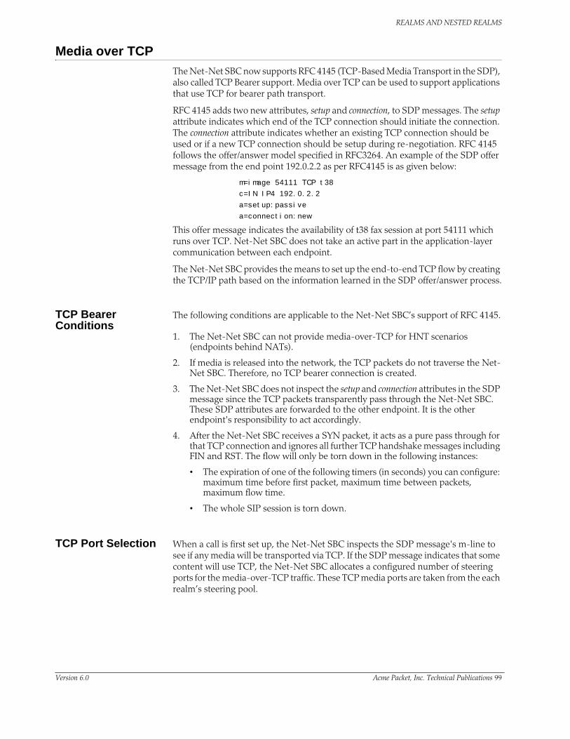
REALMS AND NESTED REALMS
Media over TCPThe Net-Net SBC now supports RFC 4145 (TCP-Based Media Transport in the SDP), also called TCP Bearer support. Media over TCP can be used to support applications that use TCP for bearer path transport.
RFC 4145 adds two new attributes, setup and connection, to SDP messages. The setup attribute indicates which end of the TCP connection should initiate the connection. The connection attribute indicates whether an existing TCP connection should be used or if a new TCP connection should be setup during re-negotiation. RFC 4145 follows the offer/answer model specified in RFC3264. An example of the SDP offer message from the end point 192.0.2.2 as per RFC4145 is as given below:
m=image 54111 TCP t38
c=IN IP4 192.0.2.2
a=setup:passive
a=connection:new
This offer message indicates the availability of t38 fax session at port 54111 which runs over TCP. Net-Net SBC does not take an active part in the application-layer communication between each endpoint.
The Net-Net SBC provides the means to set up the end-to-end TCP flow by creating the TCP/IP path based on the information learned in the SDP offer/answer process.
TCP Bearer Conditions
The following conditions are applicable to the Net-Net SBC’s support of RFC 4145.
1. The Net-Net SBC can not provide media-over-TCP for HNT scenarios (endpoints behind NATs).
2. If media is released into the network, the TCP packets do not traverse the Net-Net SBC. Therefore, no TCP bearer connection is created.
3. The Net-Net SBC does not inspect the setup and connection attributes in the SDP message since the TCP packets transparently pass through the Net-Net SBC. These SDP attributes are forwarded to the other endpoint. It is the other endpoint's responsibility to act accordingly.
4. After the Net-Net SBC receives a SYN packet, it acts as a pure pass through for that TCP connection and ignores all further TCP handshake messages including FIN and RST. The flow will only be torn down in the following instances:
• The expiration of one of the following timers (in seconds) you can configure: maximum time before first packet, maximum time between packets, maximum flow time.
• The whole SIP session is torn down.
TCP Port Selection When a call is first set up, the Net-Net SBC inspects the SDP message's m-line to see if any media will be transported via TCP. If the SDP message indicates that some content will use TCP, the Net-Net SBC allocates a configured number of steering ports for the media-over-TCP traffic. These TCP media ports are taken from the each realm’s steering pool.
Version 6.0 Acme Packet, Inc. Technical Publications 99

REALMS AND NESTED REALMS
Each endpoint can initiate up to four end-to-end TCP flows between itself and the other endpoint. The Net-Net SBC assigns one port to receive the initial TCP packet (server port), and one to four ports assigned to send TCP traffic (client ports) to the receiving side of the TCP flow. The number of TCP flows for each call is configured globally.
In order to configure the Net-Net SBC to facilitate and support this process, you need to specify the number of ports per side of the call that can transport discrete TCP flows. You can configure one to four ports/flows. For configuration purposes, the Net-Net SBC counts this number as inclusive of the server port. Therefore if you want the Net-Net SBC to provide a maximum of one end-to-end TCP flow, you have to configure two TCP ports; one to receive, and one to send. The receiving port (server) is reused to set up every flow, but the sending port (client) is discrete per flow. For example: for 2 flows in each direction, set the configuration to 3 TCP ports per flow; for 3 flows in each direction, set the configuration to 4 TCP ports per flow, etc.
The server port is used for initiating a new TCP connection. An endpoint sends the first packet to a server port on the ingress interface. The packet is forwarded out of the Net-Net SBC through a client port on the egress interface toward an endpoint:
The endpoint responds back to the client port on the egress interface. This message traverses the Net-Net SBC and is forwarded out of the server port on the ingress interface where the initial packet was sent. The remainder of the TCP flow uses the server and client port pair as a tunnel through the Net-Net SBC:
100 Net-Net 9200 EMS Configuration Guide Version 6.0

REALMS AND NESTED REALMS
When the second TCP connection is set up in the same direction as in the first example, the first packet is still received on the server port of the ingress interface. The next unused client port is chosen for the packet to exit the Net-Net SBC:
The response takes the same path back to the caller. The remainder of the second TCP connection uses this established path:
When the callee initiates a TCP connection, it must send its initial traffic to the server port on its Net-Net SBC ingress interface. The packet is forwarded out of the first free client port on the egress side of this TCP connection toward the caller.
Version 6.0 Acme Packet, Inc. Technical Publications 101

REALMS AND NESTED REALMS
The caller’s response takes the same path back to the callee that initiated this TCP connection. The remainder of the third TCP connection uses this established path.
The Net-Net SBC can support a total of eight media-over-TCP connections per call. A maximum of 4 connections are supported as initiated from each side of the call.
SDP Offer Example The following abbreviated call flow diagram sets up a media-over-TCP flow. Observe that the caller listens for audio over TCP on 172.16.0.10:10000, as described in the SDP offer (1). The Net-Net SBC re-writes the m and c lines in the SDP offer to reflect that it is listening for audio over TCP on its egress interface at 192.168.0.1:10000 (3). The Net-Net SBC then forwards the SIP invite to the callee.
The SIP callee responds with an SDP answer in a 200 OK message. The callee indicates it is listening for the audio over TCP media on 192.168.0.10:10001 (6). The Net-Net SBC re-writes the m and c lines in the SDP answer to reflect that it is listening for audio over TCP on the call's ingress interface at 172.16.0.1:10001 (7). The Net-Net SBC then forwards the SIP invite to the caller.
102 Net-Net 9200 EMS Configuration Guide Version 6.0

REALMS AND NESTED REALMS
All interfaces involved with the end-to-end TCP flow have now established their listening IP address and port pairs.
Timers The Net-Net SBC has three guard timers that ensure a TCP media flow does not remain connected longer than configured. You can set each of these from 0 (disabled) to 999999999 in seconds.
• Maximum time before first packet—Sets the maximum time in seconds allowed to elapse between the initial SYN packet and the next packet in this flow.
• Maximum time between packets—Sets the maximum time in seconds allowed to elapse between all subsequent sequential TCP packets.
• Maximum time for flow—Sets the maximum time that a single TCP flow can last. This does not refer to the entire call.
Configuring Media Over TCP
To configure media over TCP (also known as TCP bearer support):
1. Click on the Net-Net SBC you want to configure in the Net-Net EMS navigation tree. The Net-Net SBC system window appears in the display pane..
2. Click the Media control tab and scroll to TCP bearer support.
3. Maximum time before first packet (sec)—Enter the maximum time in seconds allowable before the first packet arrives.
4. Maximum time between packets (sec)—Enter the maximum time in seconds allowable between packets.
5. Maximum time for flow (sec)—Enter the maximum time in seconds allowable for the TCP flow.
6. Ports per flow—Enter the number of ports to use per flow.
7. Click Apply.
Version 6.0 Acme Packet, Inc. Technical Publications 103

REALMS AND NESTED REALMS
Media Management Behind the Same IPThe media management behind the same IP feature lets the Net-Net SBC release media when two endpoints are behind the same IP address, in the same realm. You can use this feature for both hosted NAT traversal (HNT) and non-HNT clients.
Additional Media Management Options
Additional media management options include:
• Media directed between sources and destinations within this realm on this specific Net-Net SBC. Media travels through the Net-Net SBC rather than straight between the endpoints.
• Media directed through the Net-Net SBC between endpoints that are in different realms, but share the same subnet.
• For SIP only, media released between multiple Net-Net SBCs.
To enable SIP distributed media release, you must set the appropriate parameter in the realm configuration. You must also set the SIP options parameter to media-release with the appropriate header name and header parameter information. This option defines how the Net-Net SBC encodes IP address and port information for media streams described by, for example, SDP.
Configuring Media Management Behind the Same IP
You need to configure both the mm-in-realm and mm-same-ip parameters for the realm:
• If the Within this realm serviced by this Net-Net system only is not checked (it is disabled), the Media release behind same IP setting is ignored.
• If the Within this realm serviced by this Net-Net system only is checked (enabled) and the Media release behind same IP setting is disabled, media will be managed in the realm but released if the two endpoints are behind the same IP address.
To configure media management:
1. Click Realms in the Net-Net EMS navigation tree.
The Realm window appears in the display pane.
2. Select the realm on which you want to configure media management and click Edit. The Edit Realm window appears.
3. Scroll to Manage media between endpoints.
104 Net-Net 9200 EMS Configuration Guide Version 6.0

REALMS AND NESTED REALMS
4. With this realm serviced by this Net-Net system only—Click the checkbox to enable it.
5. Scroll to Media release behind same IP.
6. Media release behind same IP—Choose enabled from the drop-down list.
7. Click Apply.
Version 6.0 Acme Packet, Inc. Technical Publications 105

REALMS AND NESTED REALMS
106 Net-Net 9200 EMS Configuration Guide Version 6.0

6 SIP Signaling Services
IntroductionThis chapter explains how to configure the Net-Net SBC to support Session Initiation Protocol (SIP) signaling services for hosted IP services applications. SIP is a text-based application-layer signaling protocol that creates, identifies, and terminates multimedia sessions between devices.
About the Net-Net SBC and SIPThis section describes the Net-Net SBC’s support of SIP. It provides the basic information you need to understand before you configure the Net-Net SBC for SIP signaling.
Types of SIP Devices
There are four types of SIP devices:
• User agent (UA) is an endpoint in SIP end-to-end communication. A UA is a user agent client (UAC) when it initiates a request and waits to receive a response. A UA is a user agent server (UAS) when it receives a request and generates a response. A given UA will be a UAC or a UAS depending on whether it is initiating the request or receiving the request.
• Proxy (or proxy server) is an intermediary entity that acts as both a server and a client for the purpose of making requests on behalf of other clients. A proxy server’s primary role is routing. Its job is to ensure that a request is sent to another entity closer to the targeted user. A proxy interprets, and if necessary, rewrites specific parts of a request message before forwarding it.
• Redirect server is a UAS that generates redirect responses to requests it receives, directing the client to contact an alternate set of targets. Unlike a proxy which forwards the request to the alternate set of targets, the redirect response tells the UAC to directly contact the alternate targets.
• Registrar is a server that accepts REGISTER requests and places the information it receives in those requests into the location service for the domain it handles. Proxies and redirect servers can use the information from the location service to determine the location of the targeted user.
A redirect server and a registrar are each a special type of UA because they act as the UAS for the requests they process.
Version 6.0 Acme Packet, Inc. Technical Publications 105

SIP SIGNALING SERVICES
Basic Service Models
The Net-Net SBC operates as a back-to-back user agent (B2BUA) within the following two basic service models:
• peering
• hosted IP services
About B2BUA A B2BUA is a logical entity that receives a request and processes it as a user agent server (UAS). In order to determine how the request should be answered, it acts as a user agent client (UAC) and generates requests. It maintains dialog state and must participate in all requests sent on the dialogs it has established.
SIP B2BUA Peering The Net-Net SBC operates as a SIP B2BUA. It terminates SIP sessions and re-originates them as new sessions as they are routed through the Net-Net SBC. For each session, it establishes NAPT translations and re-writes SDP to allow all session related media to be routed through the Net-Net SBC. It generates new call IDs and modifies SIP headers to prevent any protected SIP addresses and route information from being transmitted to external peers. The Net-Net SBC supports multiple SIP interfaces that are associated with a set of media ports, thus appearing as multiple virtual SIP gateways.
106 Net-Net 9200 EMS Configuration Guide Version 6.0

SIP SIGNALING SERVICES
B2BUA Hosted IP Services
The Net-Net SBC acts as an outbound proxy for SIP endpoints and performs the operations required to allow UAs behind NATs to initiate and terminate SIP sessions (Hosted NAT Traversal).
The Net-Net SBC caches registration requests from SIP endpoints and forwards them to the appropriate softswitch or registrar in its backbone network. All subsequent signaling between the endpoint and the backbone network is through the Net-Net SBC. Also, all calling features such as caller ID, call waiting, three-way calling, and call transfer are all supported transparently through the Net-Net SBC.
SIP B2BUA and L3/L5 NAT
For each SIP session, the Net-Net SBC establishes NAPT translations and re-writes SDP to route all session related media through the Net-Net SBC. These actions make the Net-Net SBC look like a SIP gateway. Also, the Net-Net SBC support of multiple SIP interfaces associated with different network interfaces makes it appear as multiple virtual SIP gateways.
This functionality enables the Net-Net SBC to deliver VoIP services to multiple end users, across a VPN backbone.
About SIP Interfaces
The SIP interface defines the transport addresses (IP address and port) upon which the Net-Net SBC receives and sends SIP messages. You can define a SIP interface for each network or realm to which the Net-Net SBC is connected. SIP interfaces support both UDP and TCP transport, as well as multiple SIP ports (transport addresses). The SIP interface’s SIP NAT function lets Hosted NAT Traversal (HNT) be used in any realm.
SIP Network Models and TypesYou can configure resgistration caching and SIP transport modue support of SIP registrations and endpoints. This support is enabled by configuring the network model and network type parameters.
Version 6.0 Acme Packet, Inc. Technical Publications 107

SIP SIGNALING SERVICES
Network Model The network model indicates and optimizes the Net-Net SBC whether deployed in an access or peering scenario. There is also a shared network model for deployments that fall between access and peering scenarios.
Network Type The network type is configured on each SIP interface, based upon the intended function of that SIP interface. The network type can be configured as access, used for the access side of a SIP deployment, or core, used for the core network side of a SIP deployment. In addition, the network type can be set to any, thereby functioning in both roles.
Default Network Model and Type
If you have not explicitly configured the network model, it will be determined by examining the configuration for the SIP interfaces. If any enabled SIP interface has registration caching or NAT traversal enabled, the access network model is used. If there are no SIP interfaces with registration caching or NAT traversal enabled, the peering model is used.
If you have not explicitly configured the SIP interface’s network type, it will be determined based on the registration cache and NAT traversal configuration. When registration caching or NAT traversal are enabled on a SIP interface, the access network type is used. Otherwise, the core network type is used.
Upgrade Considerations
The network model and network type parameters are dynamically configurable, however, they are not made until the SPU transitions from active to standby, or vice versa. Therefore, a manual switchover (or reboot) of the SPU is required after the configuration is activated in order for the new network model and type assignments to take affect. Hitless upgrades from a prior release are not supported. A full reboot of the Net-Net SBC is required. Please contact TAC ([email protected]) for more information.
Configuring the Network Type and Network Model
This section explains how to configure the network type and network model on the Net-Net SBC.
108 Net-Net 9200 EMS Configuration Guide Version 6.0

SIP SIGNALING SERVICES
Configuring the Network Model
To configure the network model:
1. Click then Net-Net SBC you want to configure in the Net-Net EMS navigation tree.
The Net-Net SBC system window appears in the display pane.
2. Click the SIP tab.
3. Scroll to Network model for transport balancing.
4. Network model for transport balancing—Choose the network model from the drop-down list..
• access: If any enabled SIP interface has registration caching or NAT traversal enabled, the access model is used.
• peering: If there are no SIP interfaces with registration caching or NAT traversal enabled, the peering model is used.
• shared: For deployements that fall between access and peering scenarios
5. Click Apply.
Configuring the Network Type
To configure the network type:
1. Click Realms in the Net-Net EMS navigation tree.
The Realm window appears in the display pane.
2. Click a realm in the Realm table to choose it and click Edit. The Edit realm window appears.
3. Click the Services/Protocols tab.
Version 6.0 Acme Packet, Inc. Technical Publications 109

SIP SIGNALING SERVICES
4. Click a SIP interface name to choose it and click Edit. The Edit SIP service window appears.
5. Click the SIP interface tab.
6. Scroll to Network type for transport balancing.
7. Network type for transport balancing—Choose the network type from the drop-down list..
• access: Used for the access side of a SIP deployment
• core: Used for the core network side of a SIP deployment
• any: Used when the network type is functioning in both access and core roles
8. Click Apply.
Configuring the Net-Net SBC for SIP SignalingThis section contains a diagram of a B2BUA peering environment that illustrates the Net-Net SBC components you need to configure.
110 Net-Net 9200 EMS Configuration Guide Version 6.0

SIP SIGNALING SERVICES
Refer to the following sections for details about configuring the Net-Net SBC for SIP signaling.
Using the Net-Net EMS to Configure the Net-Net SBC
You must create all new configurations and make edits to existing configurations in the Inactive configuration branch of the Net-Net EMS navigation tree. You then save and activate the Inactive configuration to apply the new configurations and edits on your Net-Net SBC.
Refer to the Net-Net EMS User Guide for detailed instructions.
Configuration Timestamp
You might see the following information on some of the configuration windows:
This is a configuration timestamp that displays last modified information for configuration changes made using Net-Net EMS.
When you make configuration changes to elements, the Last modified by field displays the following information:
• Net-Net EMS identifier
• Name of the user that made the modification
• IP address of the host machine upon which Net-Net EMS is running
• Relevant time zone information to specify how to interpret the timestamp in the Last modified date field.
For example:
EMS_admin_172.30.80.2_UTC
The Last modified date is displayed in the string date/time format, YYYY-MM-DD HH:MM:SS. For example 2007-11-07 15:16:05. When you make configuration changes using the Net-Net EMS, the date timestamp is specified in UTC.
If a sub-element is modified the timestamp belonging to the element is updated to indicate the modification time.
Configuring the Home RealmThis section explains how to configure a home realm. The home realm applies only to a SIP configuration. It represents the internal default realm or network for the Net-Net SBC and is where the Net-Net SBC’s SIP proxy is located.
Overview You primarily use a home realm when using the SIP NAT function to connect multiple realms/networks to the Net-Net SBC. You define the home realm defined as either public or private for the purposes of using the SIP NAT function. (See Configuring the SIP NAT Function (141) for more information). If the home realm is public, all external realms are considered private. If the home realm is private, all external networks are considered public. Usually the home realm is public.
Version 6.0 Acme Packet, Inc. Technical Publications 111

SIP SIGNALING SERVICES
Messages are encoded (for example, the topology is hidden) when they pass from a private to a public realm. Messages are decoded when the pass from a public realm to a private realm.
These external realms/networks might have overlapping address spaces. Because SIP messages contain IP addresses, but no layer 2 identification (such as a VLAN tag), the SIP proxy must use a single global address space to prevent confusing duplicate IP addresses in SIP URIs from different realms.
SIP NAT Function The SIP NAT function converts external addresses in SIP URIs to an internal home realm address. Usually the external address is encoded into a cookie that is added to the userinfo portion of the URI and the external address is replaced with a home realm address unique to the SIP NAT (the SIP NAT home address).
URIs are encoded when they pass from a private realm to a public realm. When an encoded URI passes back to the realm where it originated, it is decoded (the original userinfo and host address are restored). The encoding/decoding process prevents the confusion of duplicate addresses from overlapping private addresses. It can also be used to hide the private address when a SIP message is traversing a public network. Hiding the address occurs when it is a private address; or when the owner of the private network does not want the IP addresses of their equipment exposed on a public network or on other private networks to which the Net-Net SBC connects.
Home Realm’s Purpose
A home realm is required because the home address for SIP NATs is used to create a unique encoding of SIP NAT cookies. You can define the home realm as a network internal to the Net-Net SBC, which eliminates the need for an actual home network connected to the Net-Net SBC. You can define this virtual home network if the supply of IP addresses is limited (because each SIP NAT requires a unique home address), or if all networks to which the Net-Net SBC is connected must be private to hide addresses.
For example, you can define a public home realm using the loopback network (127.0.0.0) and using the home realm address prefix (for example, 127.0.0.0/8) for encoding addresses that do not match (all addresses outside 127.0.0.0/8) in SIP NAT cookies. The SIP NAT address prefix field can be used to accomplish this while keeping the ability to define an address prefix for the ream for ingress realm determination and admission control. By defining the SIP NAT address prefix as 0.0.0.0, the home realm address prefix is used to encode addresses that do not match.
Configuring the Home Realm
This section describes how to configure the SIP home realm on your Net-Net SBC from the Net-Net EMS.
112 Net-Net 9200 EMS Configuration Guide Version 6.0

SIP SIGNALING SERVICES
1. Click the Net-Net SBC you are configuring in the Net-Net EMS navigation tree.
The SBC System window appears in the Net-Net EMS display pane.
2. Click the SIP tab and then click the System sub-tab. The system information appears.
3. SIP enabled—Click the checkbox to enable the SIP functionality on this Net-Net SBC.
4. Realm name—Select the SIP home realm from the list of preconfigured realms.
5. Realm type—Select the realm type, which indicates the SIP NAT mode.
• public: Indicates the subnet defined in the addr-prefix-id field of the home realm is public and the subnet defined in the addr-prefix-id field of all external realms identified in the SIP NAT are private networks. IP addresses are encoded in SIP messages received from the external realm defined by the SIP NAT. The IP addresses are decoded in messages that are sent to the realm.
• private: Indicates the subnet defined in the addr-prefix-id field of the home realm is private and the subnet defined in the addr-prefix-id field of all external realms identified in the SIP NAT are public networks. IP addresses are encoded in SIP messages sent to the external realm defined by the SIP NAT and decoded in messages received from the realm.
• none: No SIP NAT function is necessary.
6. Default egress realm—Select the default egress realm from the drop-down list of preconfigured realms; blank is a valid selection.
7. Click Apply.
Version 6.0 Acme Packet, Inc. Technical Publications 113

SIP SIGNALING SERVICES
Configuring a SIP InterfaceThis section explains how to configure a SIP interface. The SIP interface defines the transport addresses (IP address and port) upon which the Net-Net SBC receives and sends SIP messages.
Overview The SIP interface defines the signaling interface. You can define a SIP interface for each network or realm to which the Net-Net SBC is connected. SIP interfaces support both UDP and TCP transport, as well as multiple SIP ports (transport addresses). The SIP interface also lets Hosted NAT Traversal (HNT) be used in any realm.
The SIP interface configuration process involves configuring the following features:
• address and transport protocols (SIP ports)
• redirect action
• proxy mode
• trust mode
About SIP Ports A SIP port defines the transport address and protocol the Net-Net SBC will use for a SIP interface for the realm. A SIP interface will have one or more SIP ports to define the IP address and port upon which the Net-Net SBC will send and receive messages. For TCP, it defines the address and port upon which the Net-Net SBC will listen for inbound TCP connections for a specific realm.
You need to define at least one SIP port, on which the SIP proxy will listen for connections. If using both UDP and TCP, you must configure more than one port. For example, if a call is sent to the Net-Net SBC using TCP, which it needs to send out as UDP, two SIP ports are needed.
Preferred SIP Port When a SIP interface contains multiple SIP ports of the same transport protocol, a preferred SIP port for each transport protocol is selected for outgoing requests when the specific SIP port cannot be determined. When forwarding a request that matched a cached registration entry (HNT or normal registration caching), the SIP port upon which the original REGISTER message arrived is used. Otherwise, the preferred SIP port for the selected transport protocol is used. When selecting the preferred SIP port, the default SIP port of 5060 will be selected over other non-default ports.
For SIP interfaces using the SIP NAT function, the preferred SIP port address and port will take precedence over the external address of the SIP NAT when they do not match. If both TCP and UDP SIP ports are defined, the address and port of the preferred UDP port is used.
Proxy Mode The Net-Net SBC’s proxy mode determines whether it forwards requests received on the SIP interface to target(s) selected from local policy; or sends a send a redirect response to the previous hop. Sending the redirect response causes the previous hop to contact the targets directly.
If the source of the request matches a session agent with a proxy mode already defined, that mode overrides the proxy mode defined in the SIP interface.
114 Net-Net 9200 EMS Configuration Guide Version 6.0

SIP SIGNALING SERVICES
You can configure the proxy mode to use the Record-Route option. Requests for stateless and transaction operation modes are forwarded with a Record-Route header that has the Net-Net SBC’s addresses added. As as result, all subsequent requests are routed through the Net-Net SBC.
Redirect Action The redirect action is the action the SIP proxy takes when it receives a SIP Redirect (3xx) response on the SIP interface. If the target of the request is a session agent with redirect action defined, its redirect action overrides the SIP interface’s.
You can set the Net-Net SBC to perform a global redirect action in response to Redirect messages. Or you can retain the default behavior where the Net-Net SBC sends SIP Redirect responses back to the previous hop (proxy back to the UAC) when the UAS is not a session agent.
The default behavior of the Net-Net SBC is to recurse on SIP Redirect responses received from the user agent server (UAS) and send a new request to the Contact headers contained in the SIP Redirect response.
Instead of this default behavior, the Net-Net SBC can proxy the SIP Redirect response back to the user agent client (UAC) using the value in the session agent’s redirect action field (when the UAS is a session agent). If there are too many UASes to define as individual session agents or if the UASs are HNT endpoints, and SIP Redirect responses need to be proxied for UASs that are not session agents; you can set the default behavior at the SIP Interface level.
Trust Mode The Net-Net SBC supports the Calling Identity privacy requirements based on RFC 3323 and RFC 3325. The trust mode in the SIP interface determines whether the source and destination of a request is a trusted entity. With the implementation of this feature, the Net-Net SBC can understand and support the privacy headers and provide the capability for anonymous packets.
The Net-Net SBC, which acts as a boundary device between the trusted platform and the untrusted Internet, understands the following headers:
• Privacy Header
• P-Asserted-Identity Header
• P-Preferred-Identity Header
Depending on the value of these headers and the mode in which the Net-Net SBC is being operated (B2BUA or the proxy), the appropriate actions are performed.
About the Process On receiving a message, the Net-Net SBC checks whether the message source is trusted or not. It checks the SIP interface’s trust mode value and, if the source is a session agent, the session agent’s trust me value. Depending on these values, the Net-Net SBC decides whether the request’s or response’s source is trusted. If it receives message from a trusted source and the message contains the P-Asserted-Identity header field, the Net-Net SBC passes this message to the outgoing side. The outgoing side then decides what needs to be done with this request or response.
If the request or the response is received from an untrusted source, the Privacy header value is id (privacy is requested), and the P-Asserted-Identity header field is included, the Net-Net SBC strips the Privacy and the P-Asserted-Identity headers and passes the request or the response to the outgoing side.
Version 6.0 Acme Packet, Inc. Technical Publications 115

SIP SIGNALING SERVICES
If the request or the response contains the P-Preferred-Identity header and the message source is untrusted, the Net-Net SBC strips the P-Preferred-Identity header from the request or the response and passes the message to the outgoing side.
If the source is trusted or privacy is not requested (the value of the Privacy Header is not id) and the request or the response contains the P-Preferred-Identity header, the Net-Net SBC performs the following actions:
• Inserts the P-Asserted-Identity header field with the value taken from the P-Preferred-Identity header field
• Deletes the P-Preferred-Identity header value
• Passes this request or the response to the Outgoing side for the appropriate action, depending on the whether the destination is trusted or not
After the Net-Net SBC passes the request or the response to the outgoing side, it checks whether the destination is trusted by checking the SIP interface’s trust mode value and the session agent’s trust me value (if the destination is configured as session agent).
• The destination is trusted
The Net-Net SBC does nothing with the request or the response and passes it to the destination. If the P_Asserted_Identity headers are present, they are passed to the session agent (if the destination is configured as session agent).
• The destination is untrusted
The Net-Net SBC looks at the value of the Privacy header. If set to id, the Net-Net SBC removes all the P-Asserted-Identity headers (if present). It strips the Proxy-Require header if it is set to privacy. The Net-Net SBC also sets the From field of SIP header to Anonymous and strips the Privacy header.
If the Privacy header is set to none, the Net-Net SBC does not remove the P-Asserted-Identity header fields.
If there is no Privacy header field, the SD will not remove the P-Asserted-Identity headers.
To implement this feature, you need to configure the session agent’s trust me parameter to enabled (if the message source is a session agent) and the SIP interface’s trust mode to the appropriate value.
Configuring a SIP interface
This section describes how to configure a SIP interface.
1. Click Realms in the Net-Net EMS navigation tree.
The Realm table appears in the display pane.
116 Net-Net 9200 EMS Configuration Guide Version 6.0
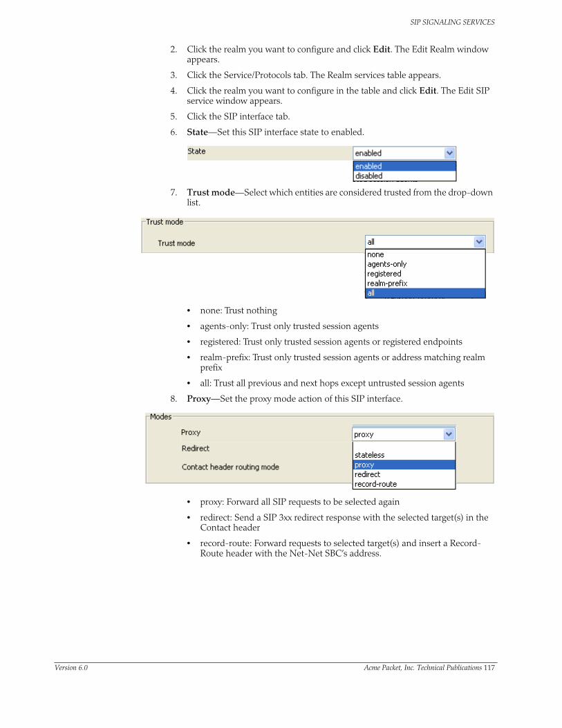
SIP SIGNALING SERVICES
2. Click the realm you want to configure and click Edit. The Edit Realm window appears.
3. Click the Service/Protocols tab. The Realm services table appears.
4. Click the realm you want to configure in the table and click Edit. The Edit SIP service window appears.
5. Click the SIP interface tab.
6. State—Set this SIP interface state to enabled.
7. Trust mode—Select which entities are considered trusted from the drop-down list.
• none: Trust nothing
• agents-only: Trust only trusted session agents
• registered: Trust only trusted session agents or registered endpoints
• realm-prefix: Trust only trusted session agents or address matching realm prefix
• all: Trust all previous and next hops except untrusted session agents
8. Proxy—Set the proxy mode action of this SIP interface.
• proxy: Forward all SIP requests to be selected again
• redirect: Send a SIP 3xx redirect response with the selected target(s) in the Contact header
• record-route: Forward requests to selected target(s) and insert a Record-Route header with the Net-Net SBC’s address.
Version 6.0 Acme Packet, Inc. Technical Publications 117

SIP SIGNALING SERVICES
9. Redirect—Set the redirect action of this SIP interface.
• proxy: Send the SIP request back to the previous hop
• recurseq: Recurses on the Contacts in the response
The designated proxy action will apply to SIP 3xx responses received from non-session agents and to 3xx responses received from session agents without configured SIP Redirect message actions (for example, session agents without values for the redirect action field).
10. Contact header routing mode—Set the Contact header routing mode, which determines how the contact address from a private network is formatted.
For example, whether a maddr parameter equal to the Net-Net SBC’s SIP proxy needs to be added to a URI present in a Contact header.
• none: The address portion of the header becomes the public address of that private realm
• maddr: The address portion of the header will be set to the IP address of the Net-Net SBC’s B2BUA
• strict: The contents of the Request-URI is destroyed when a Record-Route header is present.
• loose: The Record-Route header is included in a Request, which means the destination of the request is separated from the set of proxies that need to be visited along the way.
11. Endpoints type supported by NAT traversal—Set the type of HNT used from the drop-down list.
• none: HNT function disabled for SIP (default value).
118 Net-Net 9200 EMS Configuration Guide Version 6.0

SIP SIGNALING SERVICES
• always: SIP HNT applies to requests when the sent-by of the topmost VIA matches the Contact-URI host address, both of which must be different from the received Layer 3 address. (Even when the rport parameter is not present.)
• rport: SIP HNT function only applies to endpoints that include the rport parameter in the Via header. HNT applies when the sent-by of the topmost VIA matches the Contact-URI host address, both of which must be different from the received Layer 3 address.
12. Endpoint to SD registration interval UDP (sec)—Set the expiration time in seconds for an HNT endpoint’s cached registration entry.
• minimum: zero (0) seconds
• maximum: 999999999 seconds
Acme Packet recommends setting the NAT interval to one-third of the NAT binding lifetime. A NAT binding lifetime is the network connection inactivity timeout. The value is configured (or hardwired) in the NAT device (firewall). This timer is used to cause the UA to send REGISTER messages frequently enough to retain the port binding in the NAT. Retaining the binding lets inbound requests to be sent through the NAT.
13. SD to registrar registration interval (sec)—Set the minimum expiration time in seconds for an HNT endpoint’s cached registration entry.
The value you enter here sets the minimum registration expiration time in seconds for HNT registration caching.
• minimum: zero (0) seconds
• maximum: 999999999 seconds
The default value is 300.
This value defines the minimum expiration value the Net-Net SBC places in each REGISTER message it sends to the real registrar. In HNT, the Net-Net SBC caches the registration after receiving a response from the real registrar and sets the expiration time to the NAT interval value.
Some UAs might change the registration expiration value they use in subsequent requests to the value specified in this field. This change causes the Net-Net SBC to send frequent registrations on to the real registrar.
14. Send transactions to registrar—Set whether routing to the registrar is enabled.
Version 6.0 Acme Packet, Inc. Technical Publications 119

SIP SIGNALING SERVICES
Enable routing to the registrar to send all requests that match a cached registration to the destination defined for the registrar host; used when the Request-URI matches the registrar host value or the registrar domain value, not the Net-Net SBC’s address. Because the registrar host is the real registrar, it should send the requests back to the Net-Net SBC with the Net-Net SBC’s address in the Request-URI. By default, this field is set to disabled.
For example, you should enable routing to the registrar if your network uses a Net-Net SBC and needs requests to go through its service proxy, which is defined in the registrar host field.
15. Registration caching—Select which endpoints’ registrations are cached from the drop-down list.
Enable for use with all UAs, not just those that are behind NATs. By default, this field is set to disabled. If enabled, the Net-Net SBC caches the Contact header in the UA’s REGISTER request when it is addressed to one of the following:
• Net-Net SBC
• registrar domain value
• registrar host value
The Net-Net SBC then generates a Contact header with the Net-Net SBC’s address as the host part of the URI and sends the REGISTER to the destination defined by the registrar host value.
16. SD to register registration interval (sec)—Enter Net-Net SBC’s cached registration entry interval for a non-HNT endpoint.
Enter the expiration time in seconds that you want the Net-Net SBC to use in the REGISTER response message sent back to the UA. The UA then refreshes its registration by sending another REGISTER message before that time expires.
• minimum: zero (0) seconds
A registration interval of zero causes the Net-Net SBC to pass back the expiration time set by and returned in the registration response from the registrar.
• maximum: 999999999 seconds
The default value is 3600 seconds (one hour). If the expiration time you set is less than the expiration time set by and returned from the real registrar, the Net-Net SBC responds to the refresh request directly rather than forwarding it to the registrar.
120 Net-Net 9200 EMS Configuration Guide Version 6.0

SIP SIGNALING SERVICES
Although the registration interval applies to non-HNT registration cache entries, and the loosely related NAT interval applies to HNT registration cache entries, you can use the two in combination. Using a combination of the two means you can implement HNT and non-HNT architectures on the same Net-Net SBC. You can then define a longer interval time in the registration interval field to reduce the network traffic and load caused by excess REGISTER messages because there is no NAT binding to maintain.
Version 6.0 Acme Packet, Inc. Technical Publications 121

SIP SIGNALING SERVICES
Configuring SIP Ports To configure SIP ports:
1. Click Add in the SIP signaling interface section of the SIP service window. The Add SIP signaling interface window appears.
2. IP address—Enter the IP address of this SIP signaling interface.
3. IP port—Enter the port number of this SIP signaling interface.
• minimum: 1025
• maximum: 65535
4. Transport protocol—Enter the transport protocol this SIP signaling interface uses.
• TCP: Provides a reliable stream delivery and virtual connection service to applications through the use of sequenced acknowledgment with the retransmission of packets when necessary.
• UDP: Provides a simple message service for transaction-oriented services. Each UDP header carries both a source port identifier and destination port identifier, allowing high-level protocols to target specific applications
5. Click OK to continue.
6. Select the SIP signaling interface you just created and click Edit. The Edit SIP signaling interface window appears.
7. Anonymous mode—Select the allow anonymous criteria for accepting and processing a SIP request from another SIP element from the Anonymous mode drop-down list.
122 Net-Net 9200 EMS Configuration Guide Version 6.0

SIP SIGNALING SERVICES
• all: All requests from any SIP element are allowed.
• agents-only: Only requests from configured session agents are allowed. The session agent must fit one of the following criteria:
– have a global realm
– have the same realm as the SIP interface
– be a sub-realm of the SIP interface’s realm
• realm-prefix: The source IP address of the request must fall within the realm’s address prefix or a SIP interface sub-realm. Only realms with non-zero address prefixes are considered. Requests from configured session agents are allowed as well.
• register-prefix: Only requests from user agents that have an entry in the Registration Cache (regular or HNT) are allowed; with the exception of a REGISTER request. A REGISTER request is allowed only when the source IP address of the request falls within the realm address-prefix or a SIP Interface sub-realm. Only realms with non-zero address prefixes are considered. The Registration Cache entry is only added if the REGISTER is successful. Requests from configured session agents are also allowed.
• registered: Only requests from user agents that have an entry in the registration cache (regular or HNT) are allowed; with the exception of a REGISTER request. A REGISTER request is allowed from any user agent. The registration cache entry is only added if the REGISTER is successful. Requests from configured session agents are also allowed.
Configuring Carriers 1. Scroll to the SIP carriers area of the SIP service window and click Add.
The Add Carrier dialog box appears.
2. Select a preconfigured carrier from the drop-down list. See Adding Carriers in EMS (421) for Carrier configuration.
3. Click OK to close the SIP Carrier dialog box.
4. Click Apply to complete configuring SIP interfaces.
Version 6.0 Acme Packet, Inc. Technical Publications 123

SIP SIGNALING SERVICES
Configuring SIP TimersThis section explains how to configure SIP retransmission and expiration timers.
Overview SIP timers define the transaction expiration timers, retransmission intervals when UDP is used as a transport, and the lifetime of dynamic TCP connections. The retransmission and expiration timers correspond to the timers defined in RFC 3261.
• init timer: is the initial request retransmission interval. It corresponds to Timer T1 in RFC 3261.
This timer is used when sending requests over UDP. If the response is not received within this interval, the request is retransmitted. The retransmission interval is doubled after each retransmission.
• max timer: is the maximum retransmission interval for non-INVITE requests. It corresponds to Timer T2 in RFC 3261.
The retransmission interval is doubled after each retransmission. If the resulting retransmission interval exceeds the max timer, it is set to the max timer value.
• trans expire: is the transaction expiration timer. This value is used for timers B, D, F, H and J as defined in RFC 3261.
• invite expire: defines the transaction expiration time for an INVITE transaction after a provisional response has been received. This corresponds to timer C in RFC 3261.
If a final response is not received within this time, the INVITE is cancelled. In accordance with RFC 3261, the timer is reset to the invite expire value when any additional provisional responses are received.
• inactive dynamic conn timer: defines the idle time (no active sessions and no SIP messages sent or received) of a dynamic TCP connection before the connection is torn down. There is no timer in RFC 3261 corresponding to this function.
Configuring SIP Timers
This section describes how to configure SIP Timers on your Net-Net SBC from the Net-Net EMS.
1. Click the Net-Net SBC you are configuring in the Net-Net EMS navigation tree.
The SBC System window appears in the Net-Net EMS display pane.
2. Click the SIP tab and then click the Timers tab.
3. Responses to INVITE initial timeout - RFC 3261 timer T1 (msec)—Enter the initial timeout (T1) value for SIP in milliseconds. This value is applied to responses to INVITE requests and any UDP SIP requests. The available values include:
124 Net-Net 9200 EMS Configuration Guide Version 6.0

SIP SIGNALING SERVICES
• minimum: 0 milliseconds
• maximum: 999999999 milliseconds
4. Max. retransmit interval INVITE responses and non-INVITE requests - RFC 3261 timer T2 (msec)—Enter the maximum transmission timeout (T2) for SIP in milliseconds.
When sending SIP over UDP, a re-transmission timer is used. If the timer expires and the message is re-transmitted, the re-transmission timer is then set to twice the previous value (but will not exceed the maximum timer value). Using the default values of 500 milliseconds and 4000 milliseconds, the re-transmission timer is 0.5, then 1, 2, and finally 4. The incrementing continues until the transmission expire timer activates.
• minimum: 0 milliseconds
• maximum: 999999999 milliseconds
5. Completion of SIP transactions timeout - RFC 3261 timers, B,D,F,H,J (sec)—Enter the transaction expire timeout value (Timer B) in seconds to set the time for SIP transactions to live. The same value is used for Timers D, F, H and J.
• minimum: 0 seconds
• maximum: 999999999 seconds
6. Completion of SIP client transaction timeout - RFC 3261 timer C (sec)—Enter the invite expire timeout value (Timer C) in seconds to indicate the time for SIP client transaction will live after receiving a provisional response.
• minimum: 0 seconds
• maximum: 999999999 seconds
7. Inactive TCP/TLS-based session timeout (sec)—Enter the inactive dynamic connection value in seconds to set the time limit for inactive dynamic connections.
If the connection between the SIP proxy and a session agent is dynamic (for example, through dTCP), and the connection has been idle for the amount of time specified here, the SIP proxy breaks the connection.
• minimum: 1 second
• maximum: 999999999 seconds
8. Click Apply.
Version 6.0 Acme Packet, Inc. Technical Publications 125

SIP SIGNALING SERVICES
Configuring SIP Options Tag HandlingThis section explains how to configure SIP options on a global or per-realm level and how to specify whether the feature treatment applies to traffic inbound to or outbound from a realm, or both.
SIP extensions that require specific behavior by UAs or proxies are identified by option tags. Option tags are unique identifiers used to designate new options (for example, extensions) in SIP. These option tags appear in the Require, Proxy-Require, and Supported headers of SIP messages.
Option tags are compatibility mechanisms for extensions and are used in header fields such as Require, Supported, Proxy-Require, and Unsupported in support of SIP.
The option tag itself is a string that is associated with a particular SIP option (i.e., an extension). It identifies this option to SIP endpoints.
Overview The SIP specification (RFC 3261) requires that the Net-Net SBC B2BUA reject any request that contains a Require header with an option tag the Net-Net SBC does not support. However, many of these extensions operate transparently through the Net-Net SBC's B2BUA. You can configure how SIP defines the Net-Net SBC's B2BUA treatment of specific option tags.
Also, there might be certain extensions that an endpoint indicates support for by including the option tag in a Supported header. If you do not want a given extension used in your network, the you can configure SIP option tag handling to remove the undesired option tag from the Supported header. You can also specify how option tags in Proxy-Require headers are to be treated.
Configuration Overview
You configure the SIP feature element to define option tag names and their treatment by the Net-Net SBC when the option tag appears in a Supported header, a Require header, and a Proxy-Require header. If an option tag is encountered that is not configured as a SIP feature, the default treatments apply. You only need to configure option tag handling in the SIP feature element when non-default treatment is required.
You can specify whether a SIP feature should be applied to a specific realm or globally across realms. You can also specify the treatment for an option based on whether it appears in an inbound or outbound packet. Inbound packets are those that are coming from a realm to the Net-Net SBC and outbound packets are those which are going from the Net-Net SBC to the realm.
126 Net-Net 9200 EMS Configuration Guide Version 6.0

SIP SIGNALING SERVICES
Configuring SIP Options Tag Handling
This section describes how to configure SIP option tags on your Net-Net SBC from the Net-Net EMS.
1. Click the Net-Net SBC you are configuring in the Net-Net EMS navigation tree.
The SBC System window appears in the Net-Net EMS display pane.
2. Click the SIP tab and then click the SIP options & tags tab.
3. Under the SIP option tag table, click Add. The Add SIP option tag window appears.
4. Tag name—Enter the SIP option tag name.
5. Support header—Select the support header action for inbound tags.
6. Require header—Select the require header action for inbound tags.
7. Proxy-require header—Select the proxy-require header action for inbound tags.
8. Support header—Select the support header action for outbound tags.
9. Require header—Select the require header action for outbound tags.
Version 6.0 Acme Packet, Inc. Technical Publications 127

SIP SIGNALING SERVICES
10. Proxy-require header—Select the proxy-require header action for outbound tags.:
11. Click OK to save the values and close the window.
12. Click Apply.
128 Net-Net 9200 EMS Configuration Guide Version 6.0

SIP SIGNALING SERVICES
ENUM: Large UDP Datagram Support for DNS NAPTR ResponsesThe Net-Net SBC supports ENUM queries that manage large UDP DNS responses as set out in RFC 2671, “Extension Mechanisms for DNS (EDNS0).” It can manage responses beyond its previous 512 byte limitation.
In prior releases, the Net-Net SBC conforms with the DNS standard defined in RFC 1035 “Domain Names: Implementation and Specification,” which sets a maximum size for UDP responses at 512 bytes. This limitation means that responses larger than 512 bytes are truncated (set with the TC, or truncation, bit).
How It Works According to RFC 2671, senders can advertise their capabilities using a new resource record (OPT pseudo-RR), which contains the UDP payload size the sender can receive. You can configure the Net-Net SBC to include this resource record in its DNS queries with ENUM.
Note, however, that if your configuration does not specify a maximum response size over 512 bytes, then the Net-Net SBC will not add the OPT pseudo-RR to the ENUM query—without which the ENUM server will truncate the response.
Configuring Large UDP Datagram Support
To enable large UDP datagram support:
1. Click the Net-Net SBC you are configuring in the Net-Net EMS navigation tree.
The Net-Net SBC System window appears in the Net-Net EMS display pane.
2. Click the SIP tab.
3. Click the ENUM tab.
4. Click an ENUM configuration to choose it from the Enum config table and click Edit. The Edit Enum config window appears.
5. Maximum response size (bytes)—Enter the maximum size in bytes for UDP datagram responses. The range of values is from 512 (default) to 65535. Acme Packet recommends you do not exceed 4096 bytes.
Click Apply.
Version 6.0 Acme Packet, Inc. Technical Publications 129

SIP SIGNALING SERVICES
Configuring SIP OptionsThis section explains how you can configure a limited list of specialized SIP features and/or parameters called options. The options described here were developed to meet specific needs not addressed by the standard SIP configuration parameters. Not all users have a need for these options.
Note: Acme Packet recommends checking with your Acme Packet representative before applying any of these options.
Overview You can configure options for the SIP configuration and SIP interface. Both elements include a parameter (options) that you use to configure the options described in the following section.
Global SIP Options The following table lists the SIP options supported by the Net-Net SBC.
Option Description
add-error-to-tag=no If present (even when set to no), suppresses the addition of an Acme tag on 3xx-6xx responses.
add-prov-to-tag=no Prevents the Net-Net SBC from adding a tag parameter to the To header (to-tag) to non-100 provisional responses to INVITE requests. Used when a provisional (101-199) response is received from the UAS on a client transaction without a to-tag. By default, the Net-Net SBC adds the tag cookie in the response (as though it had a tag) sent back to the UAC for the associated server transaction. When you include this option in the SIP configuration, and the response from the UAS does not have a to-tag, the response forwarded to the UAC will not have a to-tag.
add-reg-expires Causes an Expires header to always be included in a REGISTER response with the registration caching and HNT traversal functions of the Net-Net SBC. Use for endpoints that do not understand the expires parameter in the Contact header.
add-ruri-user=<methods> Causes a userinfo portion to be added to a Request-URI when one is not present. Used to support the OKI phone, which registers a Contact of just an IP-Address but rejects initial INVITEs if the Request_URI does not have a userinfo part. <methods> is a comma-separated list of methods to which the option should apply. If more than one method is listed, the list must be enclosed in quotes. This option only applies to out-of-dialog requests (no tag parameter in the To header). However, if ACK is listed, it will apply to all ACK requests because an ACK is always supposed to have a to-tag.
allow-notify-no-contact Prevents the Net-Net SBC from rejecting illegally constructed NOTIFYs with a 400 Bad Request response. NOTIFY requests without Contact header are allowed to pass through the Net-Net SBC instead.
130 Net-Net 9200 EMS Configuration Guide Version 6.0

SIP SIGNALING SERVICES
call-id-host=<host> Causes the Net-Net SBC to include a host part (ID@host) in the Call-ID it generated.<host> is the hostname (or IP address) that is to appear in the host part of the Call-ID. If not specified, the SIP port address is used.
disable-privacy Prevents the change of the P-Preferred-Identity to P-Asserted-Identity and lets the P-Preferred-Identity go through unchanged.
drain-sendonly Causes the Net-Net SBC to examine the SDP attributes and change sendonly mode to sendrecv. This causes the endpoint receiving the SDP to send RTP, which is required for HNT traversal endpoints to work with media servers. The Net-Net SBC sets up the flow so that RTP coming from the endpoint are dropped to prevent the UA that sent the sendonly SDP from receiving packets.
See the option video-sbc-session also.
encode-contact=<prefix> Causes the Net-Net SBC to encode Contact addresses into the userinfo part of the URI. It applies only to Contact address that usually get the maddr parameter. Use when the Net-Net SBC needs requests sent to the URI in the Contact sent instead to the Net-Net SBC. The host part of the URI will have the Net-Net SBC’s address.
The <prefix> serves as a place between the original userinfo and the encoded address. If a <prefix> is specified, a default of +9200 is used. Without this option, the Net-Net SBC adds a maddr parameter.
fix-to-header For requests that have the Net-Net- SBC’s address in both the Request-URI and the To-URI, it sets the hostport of the To-URI to a local policy’s next hop target on out-of-dialog requests (no to-tag).
forward-reg-callid-change Addresses the case when an endpoint reboots and performs a third party registration before its old registration expires. During this reregistration, the contact header is the same as it was pre-reregistration. As a consequence of the reboot, the SIP Call-ID changes.In this situation, the Net-Net SBC does not forward the REGISTER to the registrar, because it believes the endpoint is already registered, based on a previous registration from the same Contact: header URI. To remedy this problem, the Net-Net SBC now keeps track of the Call-ID in its registration cache. A new option in the sip-interface configuration element forces the Net-Net SBC to forward a REGISTER message to the registrar when the Call-ID header changes in a REGISTER message received from a reregistering UAC.
global-contact Addresses interoperability in the Dialog and Presence event packages that are used in hosted PBX and IP centrex offerings. This option enables persistent URIs in the Contact headers inserted into outgoing SIP messages.If this option is not used, URIs placed in the Contact header of outgoing messages are only valid within the context of the dialog to which the message is associated.
load-limit=<cpu-percent> Defines the CPU usage percentage at which the Net-Net SBC should start rejecting calls. Default value is 95%.
Option Description
Version 6.0 Acme Packet, Inc. Technical Publications 131

SIP SIGNALING SERVICES
gateway-contact=<contact ID> (session agent)
Defines the URI parameter into which the gateway’s address is encoded.
load-limit=<cpu-percent> Defines the CPU usage percentage at which the Net-Net SBC should start rejecting calls. Default value is 95%.
gateway-contact=<contact ID> (session agent)
Defines the URI parameter into which the gateway’s address is encoded.
max-register-forward=<value> Defines a limit (as assigned in the value field) of REGISTERs to be forwarded to the registrar.During each second, the sipd counts how many REGISTERs have been sent to the registrar. It checks the threshold when it receives a REGISTER from the UA and determines that less than half the real registration lifetime is left. If the number of REGISTERs forwarded (new and updates) in the current second exceeds the configured threshold, it will respond to the UA from the cache.
max-register-refresh=<value> Defines the desired limit of REGISTER refreshes from all the UAs. Each second of time, sipd counts the number of REGISTER/200-OK responses sent back. When the threshold is exceeded, it increments the expire time (based on NAT interval) by one second and resets the count.By default no threshold is applied. The recommended value is somewhat dependent on the Net-Net SBC hardware used, but 300 can be used as an initial value.
max-routes=<number of routes> Restricts the number of routes through which the sipd will iterate from a local policy lookup. For example, setting this option to 1 causes the Net-Net SBC to only try the first, best, route. Setting this option to 0, or omitting it, lets the Net-Net SBC use all of the routes available to it (with the priority scheme for route matching).When you test a policy using the test-policy ACLI command, this option is not recognized and all options that match the criteria are displayed.
max-udp-length=<bytes> Lets you override the default value of the maximum UDP datagram size (1500 bytes; sipd requires the use of SIP/TCP at 1300 bytes). Setting this option to zero (0) forces sipd to send fragmented UDP packets.
Option Description
132 Net-Net 9200 EMS Configuration Guide Version 6.0

SIP SIGNALING SERVICES
media-release=”<header-name>[;<header-param>]”
Enables the multi-system media release feature that encodes IP address and port information for the media streams described by SDP. It lets another Net-Net SBC decode the data to restore the original SDP to allow the media to flow directly between endpoints, which is being serviced by multiple Net-Net SBCs.
The media release information can appear in the following places:• SIP header
P-Media-Release: <encoded-media-interface-information>
• Header parameter on a SIP headerContact: <sip:[email protected]> ; acme-media=<encoded-media-interface-information>
• SDP attribute in the message bodya=acme-media: <encoded-media-interface-information>
Option includes the following:
• <header-name> is SIP header in which to put the information or the special value sdp, which indicates the information should be put into the SDP.
• <header-param> is the header parameter name in which to put the information or in the case of the special header name value sdp, it is the SDP attribute name in which to put the information.
They identify to where the encoded information is passed. If you do not specify a header, P-Media-Release is used.
refer-to-uri-prefix=<prefix> Defines a prefix to be matched against the userinfo of Contact headers (config=), of which the Net-Net SBC should create a B2BUA map. This ensures that outgoing messages include the correct userinfo value. This option is used to enable add-on conferencing.
reg-cache-mode=<mode> Effects how the userinfo part of Contact address is constructed with registration caching. <mode> values are:
• none: userinfo from the received (post NAT) Contact is retained
• from: userinfo from the From header is copied to the userinfo of the forwarded Contact header
• append: append the UA’s Contact address into a cookie appended to the userinfo from the original Contact userinfo. For HNT, the NAT/firewall address is used.
• append-from: takes userinfo from the From header and appends the encrypted address to the userinfo from the original Contact userinfo. For HNT, the NAT/firewall address is used.
The from mode is used with softswitches that do not use the cookies used by the Net-Net SBC. It also helps limit the number of bytes in the userinfo; which might create duplicate contacts. For example, if the Net-Net SBC’s address is 1.2.3.4, both [email protected] and [email protected] will result in a Net-Net SBC contact of [email protected].
Option Description
Version 6.0 Acme Packet, Inc. Technical Publications 133

SIP SIGNALING SERVICES
register-grace-timer Makes the grace time for the SIP Registration configurable. You can configure the grace timer in seconds.
reinvite-trying=<yes> Causes the Net-Net SBC to send a 100 Trying for re-INVITEs, which is normally suppressed. If you enter the option name but omit the value yes, the option is still active.
reject-interval=<value> When rejecting calls because of CPU load limiting, the Net-Net SBC adds a “Retry-After” parameter to the error response (typically 503 Service Unavailable). By default the Net-Net SBC sets the Retry-After value to be 1/10th of the current rejection rate.The value you enter for this option is a multiplier used for increasing the value presented to the UAC in the Retry-After field. For example, if reject-interval=5 (reject interval is set to 10); at a 90% rejection rate the Net-Net SBC sends “Retry-After: 45”.
reject-register=no Allows REGISTER messages through even during load limiting. By default, REGISTER messages are subject to load limiting.
response-for-not-found Change the 404 Not Found generated by the Net-Net SBC to a different response code.
route-register-no-service-route Prevents the use of the Service-Route procedure to route the subsequent Register requests. If this option is not configured, the Net-Net SBC routes the Register requests using the Service-Route procedure.
set-inv-exp-at-100-resp Set Timer C when a 100 Trying response is received (instead of waiting until 1xx (> 100) is received). If the Net-Net SBC does not receive a 100 Trying response within Timer B then the call should be dropped because there is a problem communicating with the next hop.
strip-domain-suffix-route Causes sipd to strip any Route headers from the inbound messages coming to the external address of a SIP NAT; if the message contains a FQDN that matches the configured domain suffix for that SIP NAT.
video-sbc-session Use with drain-sendonly. Provides conference floor support. When configured with drain-sendonly and when the Net-Net SBC receives an SDP, the Net-Net SBC proxies the m=control and its related a= and c= unchanged. Although media streams are allocated for this m line, an actual flow is not set up.
SDP received with the following:m=videoa=sendonly
is sent out as the following:m=videoa=sendonlya=X-SBC-Session
Option Description
134 Net-Net 9200 EMS Configuration Guide Version 6.0

SIP SIGNALING SERVICES
SIP Interface Options
The following table lists the SIP interface options supported by the Net-Net SBC.
Option Description
contact-endpoint=<param-name> Defines a URL parameter to report the real Contact address of an endpoint in a REGISTER message forwarded to a registrar; when the Net-Net SBC is caching registration. (plain or HNT).If <param-name> is not specified, the default value “endpoint” is used. This parameter is added as a URL parameter in the Contact on the REGISTER message.In order for the registration cache to work properly, the softswitch/registrar is expected to include the endpoint parameter in the Request-URI of a SIP request it forwards to the address-of-record.
contact-firewall=<param-name> Defines a URL parameter to report the NAT between the Net-Net SBC and the real Contact address of an endpoint in a REGISTRAR message forwarded to a registrar when the Net-Net SBC is doing registration caching for NHT.
If <param-name> is not specified, the default value “firewall” is used.This parameter will be added as a URL parameter in the Contact on the REGISTER message.
In order for the registration cache to work properly, the softswitch/registrar is expected to include the endpoint parameter in the Request-URI of any SIP request it forwards for the address-of-record.
contact-vlan=<param-name> Adds a parameter to outbound Contact-URIs that indicates the VLAN on which the message was received. Use when two networks have overlapping IP space, so contact-firewall and contact-endpoint might have collisions.
response-for-not-found Change the 404 Not Found generated by the Net-Net SBC to a different response code.
strip-route-headers Causes the Net-Net SBC to disregard and strip all Route headers for requests received on a SIP interface.
via-header-transparency Enables the Net-Net SBC to insert its Via header on top of the top-most Via header received from user equipment (UE). It then forwards it on to the IP Multimedia Subsystem (IMS) core with the original Via header now located as the bottom-most Via header.The Net-Net SBC still replaces the Contact and other header addresses with its own, and does not pass on the core’s Via headers in outbound requests.
Version 6.0 Acme Packet, Inc. Technical Publications 135

SIP SIGNALING SERVICES
SIP Session Agent Options
The following table lists the SIP session agent options supported by the Net-Net SBC.
SIP Realm Options The following table lists the SIP realm options supported by the Net-Net SBC.
Configuring SIP Options
You access the different types of options from different windows in Net-Net EMS. The following instructions tell you how to access this different types of options. Once you have accessed the options, the process of selecting them is the same for all types.
Accessing Global Options
To access global SIP options:
1. Click the Net-Net SBC you are configuring in the Net-Net EMS navigation tree.
The Net-Net SBC System window appears in the Net-Net EMS display pane.
2. Click the SIP tab and then click the SIP options & tags tab.
Option Description
trans-timeouts=<value> Defines the number of consecutive non-ping transaction timeouts that will cause a session agent to be put out of service. The default is 1 (the existing behavior). A value of 0 prevents the session agent from going out of service because of a non-ping transaction timeout.
via-origin=<parameter-name> Causes a parameter to be included in the top Via header of requests sent to the session agent. The parameter indicates the source IP address of the corresponding request received by the Net-Net SBC. <parameter-name> defines the name of the parameter. If not specified, the default value origin is used.
Option Description
number-normalization Applies to the SIP To URI. (Currently the Net-Net SBC supports number normalization on From and To addresses for both inbound and outbound call legs.) Number normalization includes add, delete, and replace string functions that result in consistent number formats.Number normalization occurs on ingress traffic, prior to the generation of accounting records or local policy lookups.
136 Net-Net 9200 EMS Configuration Guide Version 6.0

SIP SIGNALING SERVICES
3. Click Options in the Option section.
The Options window appears.
4. Click Options. The Options window appears.
Selecting Options After you access the type of options you want, you follow the same procedure to select them in the Options window. The following instructions are for selecting a global SIP option.
1. Click the option name in the Select options scroll down list to select it.
2. Click to move the option to the Selected options list. The option name appears along with a description in the lower part of the window.
Version 6.0 Acme Packet, Inc. Technical Publications 137

SIP SIGNALING SERVICES
3. In the option name text box, enter any values needed (if any). For example:
4. Repeat steps 1 through 3 to select multiple options.
5. To enter an option you have defined, type the option name in the User defined options textbox. For example:
6. Click Add.
7. Click OK to close the Options window.
8. Click Apply.
SIP SecurityThis section provides an overview of Net-Net SBC’s security capability. Net-Net SBC security is designed to provide security for VoIP and other multi-media services. It includes access control, DoS attack, and overload protection, which help secure service and protect the network infrastructure (including the Net-Net SBC). In addition, Net-Net SBC security lets legitimate users to still place call during attack conditions; protecting the service itself.
Net-Net SBC security includes the Net-SAFE framework’s numerous features and architecture designs. Net-SAFE is a requirements framework for the components required to provide protection for the Session Border Controller (SBC), the service provider’s infrastructure equipment (proxies, gateways, call agents, application servers, and so on), and the service itself.
Denial of Service Protection
The Net-Net SBC Denial of Service (DoS) protection functionality protects softswitches and gateways with overload protection, dynamic and static access control, and trusted device classification and separation at Layers 3-5. The Net-Net SBC itself is protected from signaling and media overload, but more importantly the feature allows legitimate, trusted devices to continue receiving service even during an attack. DoS protection prevents the Net-Net SBC host processor from being overwhelmed by a targeted DoS attack from the following:
• IP packets from an untrusted source as defined by provisioned or dynamic ACLs
• IP packets for unsupported or disabled protocols
138 Net-Net 9200 EMS Configuration Guide Version 6.0

SIP SIGNALING SERVICES
• Nonconforming/malformed (garbage) packets to signaling ports
• Volume-based attack (flood) of valid or invalid call requests, signaling messages, and so on.
• Overload of valid or invalid call requests from legitimate, trusted sources
Levels of DoS protection
The multi-level Net-Net SBC DoS protection consists of the following strategies:
• Fast path filtering/access control: involves access control for signaling packets destined for the Net-Net SBC host processor as well as media (RTP) packets. The Net-Net SBC accomplishes media filtering using the existing dynamic pinhole firewall capabilities. Fast path filtering packets destined for the host processor require the configuration and management of a trusted list and a deny list for each Net-Net SBC realm (although the actual devices can be dynamically trusted or denied by the Net-Net SBC based on configuration). You do not have to provision every endpoint/device on the Net-Net SBC, but instead retain the default values.
• Host path protection: includes flow classification, host path policing and unique signaling flow policing. Fast path filtering alone cannot protect the Net-Net SBC host processor from being overwhelmed by a malicious attack from a trusted source. The host path and individual signaling flows must be policed to ensure that a volume-based attack will not overwhelm the Net-Net SBC’s normal call processing; and subsequently not overwhelm systems beyond it. The Net-Net SBC must classify each source based on its ability to pass certain criteria that is signaling- and application-dependent. At first each source is considered untrusted with the possibility of being promoted to fully trusted. The Net-Net SBC maintains two host paths, one for each class of traffic (trusted and untrusted), with different policing characteristics to ensure that fully trusted traffic always gets precedence.
• Host-based malicious source detection and isolation – dynamic deny list. Malicious sources can be automatically detected in real-time and denied in the fast path to block them from reaching the host processor.
Configuration Overview
NAT table entries are used to filter out undesired IP addresses (deny list). After the packet from an endpoint is accepted through NAT filtering, policing is implemented in the Traffic Manager based on the sender’s IP address. NAT table entries are used to distinguish signaling packets coming in from different sources for policing purposes.
You can configure deny rules based on the following:
• ingress realm
• source IP address
• transport protocol (TCP/UDP)
• application protocol (SIP, MGCP)
You can configure guaranteed minimum bandwidth for trusted and untrusted signaling paths.
You can configure signaling path policing parameters for individual source addresses. Policing parameters include:
• peak data rate in bits per second
• average data rate in bits per second
Version 6.0 Acme Packet, Inc. Technical Publications 139

SIP SIGNALING SERVICES
• maximum burst size
Configuring Security
See the Security (317) chapter in this guide for the configuration details.
SIP Delayed Media UpdateDelayed media update keeps the Net-Net SBC from updating its media flow information for flows established after an offer-answer exchange. The Net-Net SBC does not update the flow information until a new offer and answer arrive for a specific set of media flows. The (subsequent) offer does not have to be for the same session; rather, it can appear as a new SIP INVITE that uses the same SDP.
How it Works When you enable the SIP delayed media update feature, the Net-Net SBC:
• Delays changing the active media flow CAM entry for a new offer if a previous offer and answer have been received for the same media flows. It encodes new SDP information in an outgoing offer, but does not change the CAM entry until the answer is received.
• Delays changing the active media flow CAM entry even when the new offer is for a new session.
• Supports media release when performing delayed media update changes.
• Offers per-realm configuration.
This section describes how the delayed media update feature works for hairpinned call flows and for an SDP offer arriving for installed flows.
• Hairpinned call flows—The application server (AS) sends an INVITE back to the Net-Net SBC and that INVITE is forwarded to another user (user B). When it receives the offer in this INVITE and delayed media update is disabled, the Net-Net SBC determines the call is hairpinned and deletes the CAM entry for the flow for user A, who sent the initial INVITE. The Net-Net SBC deletes the CAM entry for the flow from the AS to user A.
With delayed media update enabled, the CAM entry for the flow from the AS to user A is not deleted. Instead, the Net-Net SBC waits until it has an answer from user B, and then performs the necessary updates and deletions.
• SDP offer for installed media flows—With delayed media update enabled, if it has received an offer and answer and a new offer arrives for the same flow, the Net-Net SBC delays updating the CAM entries until an answer is received for the new offer.
Configuring SIP Delayed Media Update
You enable this feature on a per-realm basis by setting one parameter.
To enable SIP delayed media update:
140 Net-Net 9200 EMS Configuration Guide Version 6.0

SIP SIGNALING SERVICES
1. Click Realms in the Net-Net EMS navigation tree.
The Realm window appears in the display pane.
2. Click a SIP interface realm to choose it and click Edit. The Edit Realm window appears.
3. Click the Realm tab.
4. Scroll to Delay media update.
5. Delay media update—Click the checkbox to enable SIP delayed media update..
6. Click Apply.
Configuring the SIP NAT FunctionThis section explains how to configure the optional SIP NAT function. You can configure the SIP NAT function if you need to translate IP address and UDP/TCP port information. The SIP NAT function also prevents private IP addresses in SIP message URIs from traveling through an untrusted network.
Overview The Net-Net SBC is an intermediary device that provides NAT functions between two or more realms. It translates IP addresses between untrusted and trusted networks using NAT. A trusted network is inside the NAT, and a untrusted network is outside the NAT. A NAT also lets a single IP address represent a group of computers.
For SIP, the SIP NAT function on the Net-Net SBC does the following:
• Routes SIP packets between the Net-Net SBC’s SIP proxy (B2BUA) and external networks (or realms), including the translation of IP address and UDP/TCP port information.
• Prevents private IP addresses in SIP message URIs from traveling through the untrusted network. SIP NAT either translates the private address to one appropriate for an untrusted address or encrypts the private address into the URI.
Packets arriving on the external address (at port 5060) are forwarded to the Net-Net SBC’s SIP proxy with the source address changed to the home address (at port 5060). When the Net-Net SBC’s SIP proxy sends packets to the home address (at port 5060), they are forwarded to the external proxy address (and external proxy port), with the source address changed to the external address (at port 5060).
Version 6.0 Acme Packet, Inc. Technical Publications 141

SIP SIGNALING SERVICES
Note: The SIP config’s NAT mode parameter works in conjunction with the SIP NAT function configuration. It identifies the type of realm in which the SIP proxy is located (public or private) and affects whether IPvr addresses in SIP messages are encoded.
The translation of URIs in the actual SIP message occurs as messages are received and sent from the Net-Net SBC’s SIP proxy. For the messages being sent to the external network, the contents of the SIP message are examined after the translation to determine if the destination needs to be changed from the external proxy address to an address and port indicated by the SIP message. This process takes place so the request is sent to where the Request-URI or the Route header indicates, or so the response is sent to where the Via indicates.
NAT Modes The specific addresses used in translating URIs in the SIP message depend on whether the Net-Net SBC is performing NAT functions for a trusted or untrusted network. This condition is determined by the NAT mode value you enter when you configure the SIP config element. The NAT modes are:
• untrusted: the SIP proxy is associated with an address for an untrusted network (the address value you entered when you configured the SIP interface’s SIP port parameter), and the home address in the SIP NAT is the address of the external realm/network. When the URI contains the external address, it is translated to the SIP NAT’s home proxy address (or to the SIP port address if the home proxy address field is empty). When a URI contains the external proxy address, it is translated to the home address.
If the URI contains any other private address (matching the realm’s address prefix, identified in the SIP NAT’s realm ID), it is encrypted and the address is replaced with the home address value. If the URI contains a user part, a suffix consisting of the user NAT tag and the encrypted address is appended to the user part. For example, with a user NAT tag value of -private-, the private URI of [email protected]:5060 will become the public URI of sip:[email protected].
If there is no user part, the host consists of the host NAT tag followed by the encrypted address and the domain suffix. A maddr parameter equal to the home address (or received in the case of a Via header) is added to the URI. For example, with a host NAT tag value of PRIVATE- and a domain suffix value of private.com, the private URI of sip:192.168.200.17:5060 will become the public URI of sip:PRIVATE-eolmhet2chbl3.private.com:5060;maddr=172.16.0.15.
• trusted: the SIP proxy is on a trusted network (the address value you entered when you configured the SIP interface’s SIP port parameter), and the SIP NAT’s external address is the public address of the external realm/network. When the URI contains the home address value, it is translated to the value set for the external proxy address. When the URI contains the SIP proxy’s address, it is translated to the external address. If the URI contains any other private address (matching the realm’s address prefix, identified in the SIP NAT’s realm ID), the private address is encrypted and the address is replaced with the external address.
Note: Do not use the home proxy address value with private NAT functioning.
Adding a maddr Parameter to a URI
When you configure a SIP interface, you can configure the contact mode. The contact mode sets the contact header routing mode, which determines how the contact address from a trusted network is formatted. You set the contact mode to add
142 Net-Net 9200 EMS Configuration Guide Version 6.0

SIP SIGNALING SERVICES
a maddr parameter equal to the SIP proxy to the URI in the Contact header. For example, the URI from the prior example (sip:192.168.200.17:5060) becomes sip:[email protected];maddr=172.16.0.12.
Note: For SIP elements that do not support the maddr parameter, configure a Contact mode as none.
You might require this encryption to cause other SIP elements in the untrusted network to send requests directly to the SIP proxy. Otherwise, the requests are sent to the home address. However, responses sent by the SIP proxy will have the SIP proxy’s source address, rather than the home address. Some SIP elements might drop responses that come from a IP address different from the one to which the request is sent.
Version 6.0 Acme Packet, Inc. Technical Publications 143

SIP SIGNALING SERVICES
About Headers You can specify which SIP headers you want effected by the SIP NAT function. The URIs in these headers are translated and encrypted, the encryption occurs according to the rules of this SIP NAT function.
You can enter header values by using either the full header name or its corresponding abbreviation, if applicable. The following table lists the available headers and their corresponding abbreviations
SIP sessions are terminated and re-originated as new sessions as they are routed through the Net-Net SBC. Among the actions performed, SIP headers are modified to prevent the transmission of IP address and route information.
Replacing Headers In the SIP signaling message, any Via headers are stripped out and a new one is constructed with the Net-Net SBC’s IP address in the sent-by portion. If a Contact header is present, it is replaced with one that has the Net-Net SBC’s IP address. All other headers are subject to NATing based on the following rules:
• The Request-URI is replaced with the next hop’s IP or FQDN address.
• All other headers are replaced based on the two SIP NAT function SIP NAT function rules
Mapping FQDNs The Net-Net SBC maps FQDNs that appear in the certain headers of incoming SIP messages to the IP address that the Net-Net SBC inserts in outgoing SIP contact headers. The mapped FQDNs are restored in the SIP headers in messages that are sent back to the originator.
This feature is useful to carriers that use IP addresses in the SIP From address to create trunk groups in a softswitch for routing purposes. When the carrier’s peer uses FQDNs, the carrier is forced to create trunk groups for each possible FQDN that it might receive from a given peer. Similarly, this can apply to SIP Contact and P-Asserted-Identity headers.
Header Abbreviation
Call-ID i
Contact m
From f
Record-Route none
Route none
Ready-To none
Replaces none
Refer-To r
To t
Via v
144 Net-Net 9200 EMS Configuration Guide Version 6.0

SIP SIGNALING SERVICES
SIP NAT Function Cookies
Cookies are inserted to hide that information is coming from a realm external to the home realm. They are used when information needs to be placed into a given element of a SIP message that must also be seen in subsequent SIP messages within a flow. When forwarding a SIP message, the Net-Net SBC encodes various information in the outgoing message, which is passed from one side to another in SIP transactions.
SIP NAT function cookies let the Net-Net SBC hide headers, IP addresses, and SIP URIs. These cookies are included when certain conditions are present in Net-Net SBC SIP transactions.
Acme Packet’s SIP NAT function cookies can be used in the userinfo, host, URL parameter, and tel URL parameter portions of the SIP message.
userinfo The Net-Net SBC places a cookie in the userinfo portion of a SIP URI when a SIP header contains a SIP URI, and includes that header type in the list of headers to be hidden (encrypted) in the associated SIP NAT function. The cookie for the userinfo portion is the following:
[user nat tag][encrypted 13-byte host IP][encrypted 13 byte maddr IP (if
present)]
where:
• [user nat tag] refers to the SIP NAT function’s original user NAT tag field.
• [encrypted 13-byte host IP] refers to the host IP encryption.
• [encrypted 13 byte maddr IP (if present)] refers to the maddr IP encryption, if it exists.
With a user NAT tag of -acme, the following SIP-URI:
might be translated into:
Note: Multiple additional cookies might be appended with each hop (for example, from the external proxy to the home proxy and back).
host When hiding IP addresses in a SIP message, the SIP NAT function generates the following cookie for a SIP-URI with no userinfo portion:
[host nat tag][encrypted 13-byte host IP][encrypted 13 byte maddr IP (if
present)][domain suffix]
where:
• [host nat tag] refers to the SIP NAT function’s host NAT tag.
• [encrypted 13-byte host IP] refers to the host IP encryption.
• [encrypted 13 byte maddr IP (if present)] refers to the maddr IP encryption, if it exists.
• [domain suffix] refers to the SIP NAT function’s domain suffix field.
Version 6.0 Acme Packet, Inc. Technical Publications 145

SIP SIGNALING SERVICES
With a SIP NAT function’s host tag of ACME- and a domain suffix of .acme.com, the following SIP header:
Via: SIP/2.0/UDP 192.168.1.100:5060
might be translated into the following:
Via: SIP/2.0/UDP ACME-pfi1s7n2pstna.acme.com
URL Parameter If the SIP NAT function’s use url parameter field has a value of from-to or all, the SIP NAT function places all cookies generated to hide SIP URIs in a custom tag appended to the header. Setting the use url parameter field to:
• from-to only affects the behavior of the SIP NAT function’s cookies in the From and To headers.
• all affects all SIP headers processed by the SIP NAT function
The cookie is the following:
[;url-parameter]=[host nat tag][encrypted 13-byte host IP][encrypted 13-
byte maddr IP]
where:
• [;url-parameter] refers to the SIP NAT function’s parameter name field.
This cookie type is associated with the all and from-to field value options of the SIP NAT function’s use url parameter field.
• [host nat tag] refers to the SIP NAT function’s host NAT tag field.
• [encrypted 13-byte host IP] refers to the host IP encryption.
• [encrypted 13 byte maddr IP (if present)] refers to the maddr IP encryption, if it exists.
With a host NAT tag of ACME- and a parameter name of acme_param, the following SIP-URI:
might be translated into the following:
sip:[email protected];acme_param=ACME-pfi1s7n2pstna.
tel URL The SIP NAT function cookie is used when devices in your network are strict about the context portion of SIP messages regarding the conversion of tel URLs. This cookie for the tel URL parameter portion of a SIP message is the following:
“tel” URL parameter-[13-byte host IP][13 byte optional maddr IP]domain
suffix
where:
• tel URL parameter refers to the SIP NAT function’s use url parameter.
This cookie type is associated with the use url parameter’s phone field value for the SIP NAT.
• [13-byte host IP] refers to the host IP encryption.
• [13 byte optional maddr IP] refers to the maddr IP encryption, if it exists.
• domain suffix refers to the SIP NAT function’s domain suffix field.
146 Net-Net 9200 EMS Configuration Guide Version 6.0

SIP SIGNALING SERVICES
Configuration Overview
Configuring the SIP NAT function falls into two areas, the SIP NAT interface parameters and the SIP NAT policies.
SIP NAT Interface The following tables lists the SIP NAT function interface parameters you need to configure.
Parameter Description
realm ID Name of the external realm. The realm ID must be unique; no two SIP NATs can have the same realm ID.This realm ID must also correspond to a valid realm identifier entered when you configured the realm.
external proxy address IP address of the SIP element (for example, a SIP proxy) in the external network with which the Net-Net SBC communicates. Entries must follow the IP address format.
external proxy port UDP/TCP port of the SIP element (for example, a SIP proxy) in the external network with which the Net-Net SBC communicates.Minimum value is 1025, and maximum value is 65535. Default is 5060.
external address IP address on the media interface in the external realm. Enter a value that ensures any packet with an external address value as its destination address is routed to the Net-Net SBC through the media interface connected to or routable from the external realm. Entries must follow the IP address format.To specify whether the external realm referenced in this field is private or public, configure the SIP config’s NAT mode.
home address IP address on the media interface in the home realm. Enter a value that ensures any packet with a home address value as its destination address must be routed to the Net-Net SBC through the media interface connected to or routable from the home realm. Entries must follow the IP address format.The value entered in this field must be different from the IP address value of the home realm’s network interface element.The home realm network interface is associated with this SIP NAT by its realm ID and the realm’s identifier and network interface value you entered when you configured the realm. The realm’s network interface identifier value corresponds to this SIP NAT’s realm ID, the SIP config’s home realm ID, and the media manager’s home realm ID.
home proxy address Sets the IP address for the home proxy (from the perspective of the external realm).By default, this field is empty.An empty home proxy address field value signifies that there is no home proxy, and the external address will translate to the address of the Net-Net SBC’s SIP proxy. Entries must follow the IP address format.
Version 6.0 Acme Packet, Inc. Technical Publications 147

SIP SIGNALING SERVICES
SIP NAT Function Policies
The following tables lists the SIP NAT function policy parameters you need to configure.
home proxy port Sets the port number for the home realm proxy. Value can be set to zero (0). Minimum is 1025 and maximum is 65535. Default is 5060.
route home proxy Whether to route all inbound requests for the SIP NAT to the home proxy. • enabled adds route if Request-URI is not the Net-Net
SBC• disabled does not route inbound requests to the
home proxy• forced always adds route
Parameter Description
Parameter Description
domain suffix Domain name suffix of the external realm. The domain name suffix refers to and must conform to the hostname part of a URI. In combination with the user NAT tag and host NAT tag values, this value is used to help the Net-Net SBC identify an encoded URI that it needs to translate when moving between public and private realms.This suffix is appended to encoded hostnames that the SIP NAT function creates. For example, if the encoded hostname is ACME-abc123 and the domain-suffix value is .netnetsystem.com, the resulting FQDN will be ACME-abc123.netnetsystem.com.
address prefix Defines which IP address prefixes from incoming messages require SIP-NAT encoding (regardless of the realm from which these messages came).
tunnel redirect Controls whether Contact headers in a 3xx Response message received by the Net-Net SBC are NATed when sent to the initiator of the SIP INVITE message.
use url parameter Establishes whether SIP headers will use the URL parameter entered in the parameter name for encoded addresses that the SIP NAT function creates. Also, if SIP headers will be used, which type of headers will use the URL parameter. For example, all headers or just the From and To headers. Enumeration field.
parameter name Indicates the name of the URL parameter when use url applies. This field value will be used in SIP NAT encoding addresses that have a use url parameter value of either from-to or all.
user NAT tag Identifies the prefix used when an address is encoded into the username portion of user@host;name=xxxx; where name = parameter name.The user NAT tag values can consist of any characters that are valid for the userinfo part of a URI. In combination with the domain suffix and host NAT tag field values, this value is used to help the Net-Net SBC identify an encoded URI that it needs to translate when moving between public and private realms.
148 Net-Net 9200 EMS Configuration Guide Version 6.0
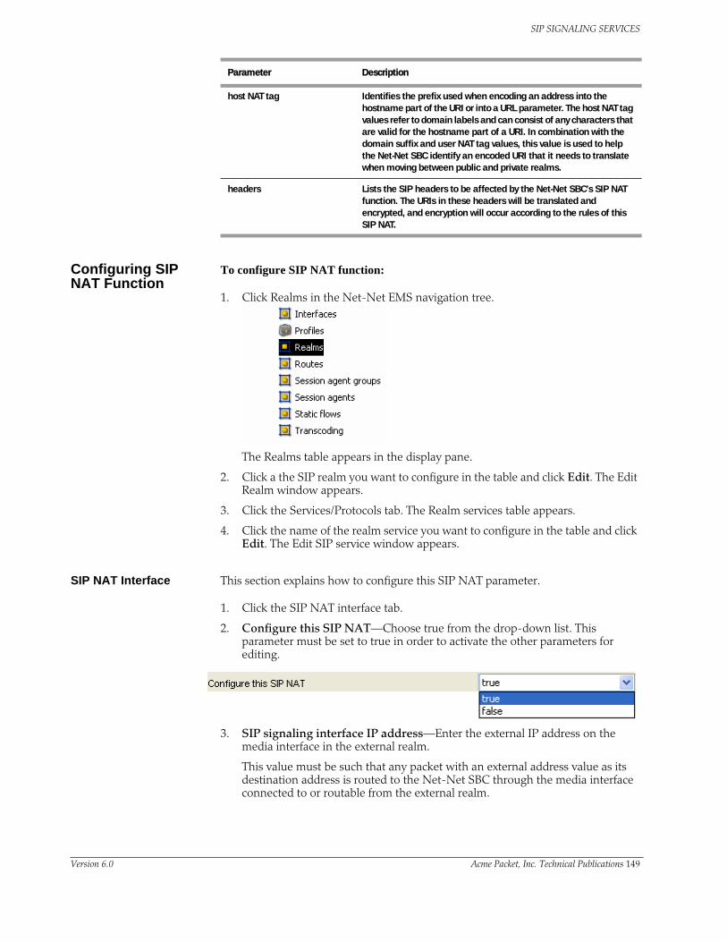
SIP SIGNALING SERVICES
Configuring SIP NAT Function
To configure SIP NAT function:
1. Click Realms in the Net-Net EMS navigation tree.
The Realms table appears in the display pane.
2. Click a the SIP realm you want to configure in the table and click Edit. The Edit Realm window appears.
3. Click the Services/Protocols tab. The Realm services table appears.
4. Click the name of the realm service you want to configure in the table and click Edit. The Edit SIP service window appears.
SIP NAT Interface This section explains how to configure this SIP NAT parameter.
1. Click the SIP NAT interface tab.
2. Configure this SIP NAT—Choose true from the drop-down list. This parameter must be set to true in order to activate the other parameters for editing.
3. SIP signaling interface IP address—Enter the external IP address on the media interface in the external realm.
This value must be such that any packet with an external address value as its destination address is routed to the Net-Net SBC through the media interface connected to or routable from the external realm.
host NAT tag Identifies the prefix used when encoding an address into the hostname part of the URI or into a URL parameter. The host NAT tag values refer to domain labels and can consist of any characters that are valid for the hostname part of a URI. In combination with the domain suffix and user NAT tag values, this value is used to help the Net-Net SBC identify an encoded URI that it needs to translate when moving between public and private realms.
headers Lists the SIP headers to be affected by the Net-Net SBC’s SIP NAT function. The URIs in these headers will be translated and encrypted, and encryption will occur according to the rules of this SIP NAT.
Parameter Description
Version 6.0 Acme Packet, Inc. Technical Publications 149

SIP SIGNALING SERVICES
4. SIP session agent IP address—Enter the session agent’s (proxy’s) IP address in the external realm with which the Net-Net SBC communicates.
5. SIP session agent IP port—Enter the session agent’s (proxy’s) IP address’s external proxy port value to identify the UDP/TCP port in the external realm which which the Net-Net SBC communicates. Values are:
• minimum: 1025
• maximum: 65535
6. Home realm addressing IP address—Enter the IP address on the network interface in the home realm. This value must be such that any packet with a home address value as its destination address must be routed to the Net-Net SBC through the media interface connected to or routable from the home realm.
The value entered in this field must be different from the IP address value of the home realm’s network interface element.
The home realm network interface is associated with this SIP NAT by its realm ID and the realm’s identifier and network interface value you entered when you configured the realm. The realm’s network interface identifier value corresponds to this SIP NAT’s realm ID, the SIP configuration’s home realm ID, and the media manager’s home realm ID
7. Proxy IP address—Enter the home proxy address to set the IP address for the home proxy (from the perspective of the external realm).
By default, this field is empty. No home proxy address entry signifies there is no home proxy, and the external address will translate to the address of the Net-Net SBC’s SIP proxy
8. Proxy IP port—Enter the home proxy port portion of IP address. Values are:
• empty
• minimum: 1025
• maximum: 65535
9. Proxy routing—Select the behavior of how to route inbound requests through the home proxy.
• enabled: all inbound requests for a specific SIP NAT are routed to the home proxy
• disabled: all inbound requests are not routed through the home proxy
150 Net-Net 9200 EMS Configuration Guide Version 6.0

SIP SIGNALING SERVICES
• forced: The request is forwarded to the home proxy without using a local policy.
SIP NAT Policies 1. Realm IP address prefix override—Enter the IP address prefix to match for this SIP NAT.
2. Return REDIRECT (3##) responses without NAT—Select the behavior of NAT for certain headers in a 3xx Response message when sent to the initiator of the SIP INVITE message.
• enabled: certain headers in a 3xx Response message are NATed.
• disabled (default): certain headers in a 3xx Response message are not NATed.
3. User name prefix—Enter a value to identify the username prefix used for SIP URIs. The values you can use can include any characters valid for the userinfo part of a URI. This should be made unique for each realm and SIP NAT function.
In combination with the domain suffix and host NAT tag values, this value is used to help the Net-Net SBC identify an encoded URI that it needs to translate when moving between public and private realms.
4. Host name prefix—Enter a value for the host NAT tag field to identify the hostname prefix used for SIP URIs. The value refers to domain labels and can include any characters valid for the hostname part of the URI. This should be made unique for each realm and SIP NAT function.
In combination with the domain suffix and user NAT tag values, this value is used to help the Net-Net SBC identify an encoded URI that it needs to translate when moving between public and private realms.
5. Domain name prefix—Enter the domain suffix of external realm. The domain name suffix refers to and must conform to the hostname part of a URI.
6. Special name tag—Select the behavior of how the Net-Net SBC uses the URL parameter for encoded addresses created by the SIP NAT function. If SIP headers will be used, this value identifies which types of headers will use the URL parameter. Values are:
• none: no headers will use the URL parameter for address encoding. The following example illustrates the functionality of a Net-Net SBC using a use url parameter value of none:
sip: [email protected] is translated into sip: [email protected]
where -acme-xxxx is a cookie and xxxx is the encoded version of 1.2.3.4.
Version 6.0 Acme Packet, Inc. Technical Publications 151

SIP SIGNALING SERVICES
• from-to: From and To headers will use the URL parameter for address encoding. The following example illustrates the functionality of a Net-Net SBC using a use url parameter value of none:
sip: [email protected] is translated into sip: [email protected]; pn=acme-xxxx
where -acme-xxxx is a cookie and xxxx is the encoded version of 1.2.3.4.
• all: all headers will use the URL parameter for address encoding. Acme Packet recommends not using this value because other SIP elements or implementations (other than the Net-Net SBC) might not retain the URL parameter in subsequent SIP messages that they send to the Net-Net SBC.
• phone:
If this field is set to either from-to or all, the Net-Net SBC puts the encoded address of the SIP NAT into a URL parameter instead of using the encoding name inside the userinfo part of the address.
7. Parameter name—Enter the hostname prefix to use if Special Name Tag drop-down list is set to from-to or all.
The parameter name value is used in SIP NAT encoding addresses that have the use url parameter values of from-to or all.
8. Click Add in the SIP NAT headers portion of the screen. The Add SIP Header dialog box appears.
9. Action—Select the behavior of header replacement from the Action drop-down list.
• Replace FQDN with next hop SIP address: Replaces the FQDN with the target address
• Replace FQDN with SD SIP interface address: Replaces the FQDN with the SIP NAT external address
• Replace any IP address with next hop SIP address: Replaces any IP address in the From header with the next hop target
• Replace any IP address with SD SIP interface addres: Replaces any IP address in the From header with the Net-Net SBC’s external address
152 Net-Net 9200 EMS Configuration Guide Version 6.0

SIP SIGNALING SERVICES
10. SIP Header—Enter the SIP header you want affected by the SIP NAT function in the SIP header field.
The URI in the header is translated, encrypted according to the SIP NAT function rule.
11. Click OK to save the information and close the window.
12. Click Apply.
Configuring SIP Realm Bridging This section explains how to configure the internal routing among realms known as realm bridging. Realm bridging lets you cross-connect SIP interfaces. You can use one of the following two methods for bridging realms:
• local policy bridging: use this method to enable dynamic internal routing between realms if your SIP interfaces do not have the SIP NAT function applied.
• SIP NAT bridging: use this method if your SIP interfaces have the SIP NAT function applied.
About SIP NAT Bridging
Each SIP NAT has a presence in two realms, trusted and untrusted. The SIP NAT bridge is the conduit for packages in and out of the home realm. It creates a bridge between realms by providing address translations; removing all references to the original IP addressing from the packets sent to the destination network.
With the SIP NAT bridge, an untrusted (or public) home network can reside within the Net-Net SBC, while the other entities (the backbone network, the Internet, or customer networks) are all trusted (or private). One of the primary functions of the SIP NAT bridge is to protect networks from one another so that address bases can remain hidden. Using a SIP NAT bridge, no one network has direct access to the data of other networks.
Establishing a SIP NAT bridge lets you route every SIP Request message through the backbone. Without using this functionality, it would appear as though all messages/sessions were coming from the Net-Net SBC’s SIP proxy (the SIP server that receives SIP requests and forwards them on behalf of the requestor).
Version 6.0 Acme Packet, Inc. Technical Publications 153

SIP SIGNALING SERVICES
The following diagram illustrates this unprotected (or public) and protected (or private) division.
SIP NAT Bridge Configuration Scenarios
You can configure the SIP NAT bridge functionality in a many-to-one or a one-to-one relationship. For example, multiple customer SIP NATs can be tied to a single backbone SIP NAT, or a single customer SIP NAT can be tied to a single backbone SIP NAT.
You might need to use several SIP NATs on the customer side while using only one on the backbone side in a many-to-one relationship. Or you might configure one SIP NAT on the backbone side for every one that you configure on the customer side in a one-to-one relationship.
You can route all customer side SIP NAT requests to the corresponding backbone SIP NAT regardless of the Request URI.
154 Net-Net 9200 EMS Configuration Guide Version 6.0
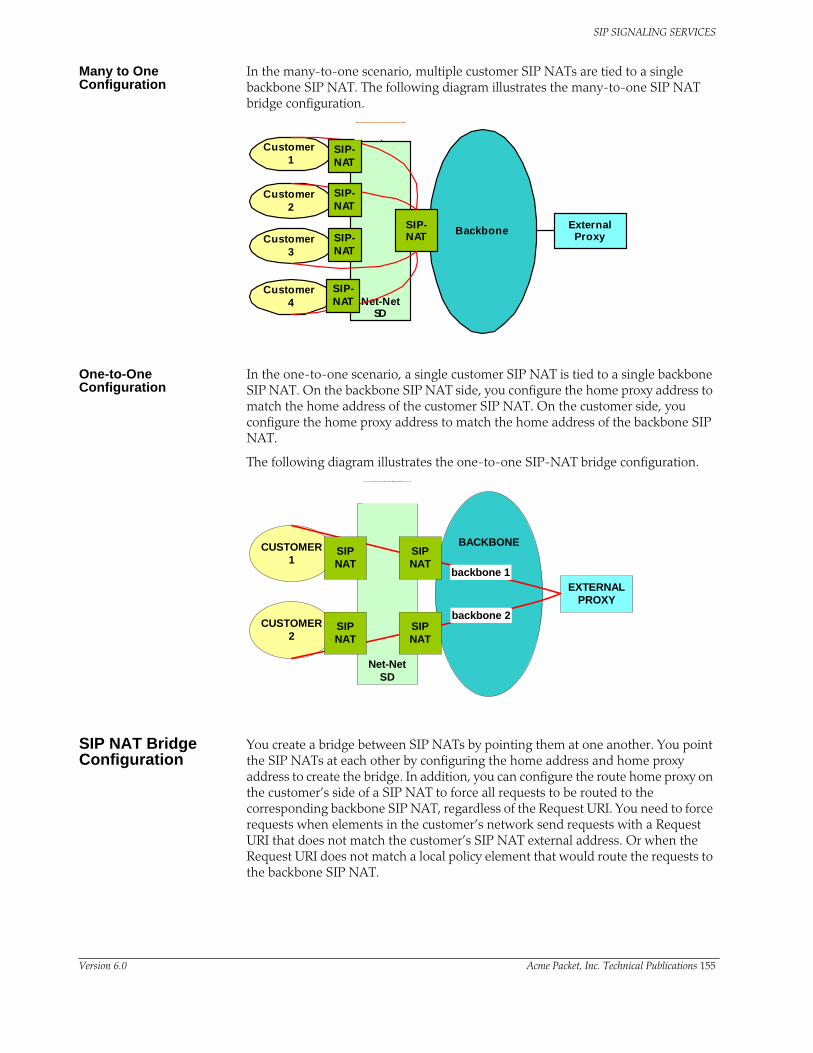
SIP SIGNALING SERVICES
Many to One Configuration
In the many-to-one scenario, multiple customer SIP NATs are tied to a single backbone SIP NAT. The following diagram illustrates the many-to-one SIP NAT bridge configuration.
One-to-One Configuration
In the one-to-one scenario, a single customer SIP NAT is tied to a single backbone SIP NAT. On the backbone SIP NAT side, you configure the home proxy address to match the home address of the customer SIP NAT. On the customer side, you configure the home proxy address to match the home address of the backbone SIP NAT.
The following diagram illustrates the one-to-one SIP-NAT bridge configuration.
SIP NAT Bridge Configuration
You create a bridge between SIP NATs by pointing them at one another. You point the SIP NATs at each other by configuring the home address and home proxy address to create the bridge. In addition, you can configure the route home proxy on the customer’s side of a SIP NAT to force all requests to be routed to the corresponding backbone SIP NAT, regardless of the Request URI. You need to force requests when elements in the customer’s network send requests with a Request URI that does not match the customer’s SIP NAT external address. Or when the Request URI does not match a local policy element that would route the requests to the backbone SIP NAT.
Customer1
Customer2
Net-NetSD
Backbone ExternalProxy
SIP-NATCustomer
3
Customer4
SIP-NAT
SIP-NAT
SIP-NAT
SIP-NAT
CUSTOMER1
CUSTOMER2
Net-NetSD
BACKBONE
Proxy
EXTERNALPROXY
backbone 2
backbone 1
SIPNAT
SIPNAT
SIPNAT
SIPNAT
Version 6.0 Acme Packet, Inc. Technical Publications 155

SIP SIGNALING SERVICES
You also need a home network to create a SIP NAT bridge. If you do not have a real home network, you need to create a virtual one. You also need to configure instances of the SIP NAT to create the SIP NAT bridge within your network.
Creating a Virtual Home Network
A virtual home network is a home network that resides entirely within the Net-Net SBC, as does a real home network. The difference between the two is the real home network also has a physical connection to the Net-Net SBC.
The internal home realm/network is usually configured with addresses within the special loopback range (127.0.0.0/8) as described in RFC 3330. This applies to the SIP port addresses for the home realm's SIP interface, and all home addresses for SIP NATs. The address 127.0.0.1 should not be used because it conflicts with the default loopback interface setup by the system for inter-process communication.
To create a virtual home network:
1. Set the name and subport ID of the network interface associated with the home realm element to lo0:0.
2. To enable the SIP proxy to listen for messages on the virtual home realm, configure the home realm ID. It must correspond to the realm’s identifier, in which you set the network interface subelement to point to the appropriate network interface element.
The following table lists the field values you need to set when you are using SIP NAT bridge functionality and you do not have a real home network.
Many-to-One Configuration
To configure many-to-one:
1. For the backbone SIP NAT, ensure the home proxy address field is blank.
2. For the customer side SIP NAT, set the home address to match the home address of the customer.
3. For the customer side SIP NAT, set the home proxy address to match the backbone SIP NAT home address.
Configuration Element
Sample Values
realm configuration identifier home
network interfaces lo0:0
address prefix 127.0.0.0/8
SIP configuration home realm ID home
SIP ports address 127.0.0.100
156 Net-Net 9200 EMS Configuration Guide Version 6.0

SIP SIGNALING SERVICES
The following table lists the field values you need to set to create a many-to-one SIP NAT bridge.
One-to-One Configuration
In the one-to-one scenario, a single customer SIP NAT is tied to a single backbone SIP NAT. The home proxy address field value of the backbone SIP NAT must match the home address of the customer SIP NAT. On the customer side, the home address of the customer SIP NAT should be defined as the home address of the customer, the home proxy address field value should match the home address of the backbone SIP NAT, and route home proxy should be set to forced.
The following table lists the field values you need to set to create a one-to-one SIP NAT bridge.
Shared Session Agent
Usually, the same set of servers (the external proxy) is used for all SIP NATs to the backbone network. In order to support redundant servers in the backbone of a SIP NAT bridge, the original egress realm as determined by the incoming Request URI needs to be retained after a local policy lookup.
When a request arrives at the Net-Net SBC, it determines the matching (target) session agent and, after the local policy is examined, sets the new outbound session agent to the one from the selected target.
If the target session agent’s realm is set to *, the Net-Net SBC retains the original session agent’s realm ID. Because the target session agent does not have a realm ID defined, the original egress realm is retained.
SIP NAT Entity Field Sample Values
Backbone SIP NAT home address IP address of the home realm. For example:127.0.0.120
home proxy address IP address of the home proxy from the perspective of the external realm.For a backbone SIP NAT, leave blank.
Customer SIP NAT home address 127.0.0.120
home proxy address 127.0.0.110
SIP NAT Entity Field Sample Values
Backbone SIP NAT home address IP address of the home realm. For example:127.0.0.110
home proxy address IP address of the home proxy from the perspective of the external realm.127.0.0.120
Customer SIP NAT home address 127.0.0.120
home proxy address 127.0.0.110
Version 6.0 Acme Packet, Inc. Technical Publications 157

SIP SIGNALING SERVICES
Configuring SIP Hosted NAT TraversalThis section explains how to configure SIP Hosted Network Address Translation (HNT) traversal. SIP HNT lets endpoints (any system detected behind a NAT) behind a NAT/firewall device send and receive signaling and media using the Net-Net SBC as a relay.
About SIP HNT SIP HNT is a technique the Net-Net SBC uses to provide persistent reachability for SIP UAs located in private Local Area Networks (LANs) behind Nat/firewall devices. It relies on frequent, persistent messaging to ensure that the binding on the intermediary NAT device is not torn down because of inactivity. HNT does not require support for the NAT in the SIP endpoint.
The following diagram illustrates SIP HNT traversal.z
The Net-Net SBC’s HNT function allows endpoints located behind NATs to communicate; providing means to traverse NATs. The Net-Net SBC interacts with endpoints (using SIP) to allow persistent inbound and outbound signaling and media communications through these NATs.
The Net-Net SBC automatically detects when an intermediate NAT exists between the UA and the Net-Net SBC by comparing the Layer 3 IP address of a REGISTER message with the IP address indicated within the UA. The Net-Net SBC sends signaling responses to the address and port that the request came from, rather than the address and port indicated in the request. The Via header in the request message indicates where the response should be sent.
Using HNT with Existing NAT Device
For network architectures in which premise devices and endpoints reside behind an existing NAT device, the Net-Net SBC’s HNT function allows these premise NATs to be traversed without requiring an upgrade to the premise equipment, the deployment and management of additional premise-based hardware or software, or any NAT device configuration changes.
158 Net-Net 9200 EMS Configuration Guide Version 6.0

SIP SIGNALING SERVICES
Registering Endpoints The Net-Net SBC uses periodic endpoint registration messages to dynamically establish and maintain bindings in the NAT. These bindings keep a signaling port (port that is opened on a firewall to allow traffic to pass through it is a pinhole) open in the NAT that allows the inbound signaled communications to pass through. Using the endpoint registrations, the Net-Net SBC then maps the Layer 3 (OSI network layer that deals with switching and routing technologies for data transmission between network devices) IP address/port information from the NAT device to the Layer 5 (OSI session layer that deals with session and connection coordination between applications) entity (for example, user name or phone number) behind the NAT so that when an incoming signaling message is received, the Net-Net SBC sends it to the appropriate address and port on the NAT for the called party.
Establishing Media Flows
During call setup, the ports for bidirectional media flows are established dynamically. Since the media flows also pass through the Net-Net SBC, it can identify the IP address/port information on the NAT device used for the outgoing media coming from the user name/phone number. The Net-Net SBC then uses that same NAT’s IP address/port information to send incoming media to the correct user name/phone number behind the NAT device.
Prerequisites In order to achieve HNT, the endpoints involved must be capable of:
• symmetric signaling: sending and receiving SIP messages from the same transport address (IP address or User Datagram Protocol/Transmission Control Protocol (UDP/TCP) port
• symmetric media: sending and receiving Real-Time Transport Protocol (RTP) messages from the same UDP port
These conditions are required to allow signaling and media packets back through the NAT (through the bound external address and port). These packets must come from the address and port to which the outbound packet that created the NAT binding was sent. The NAT sends these inbound packets to the source address and port of the original outbound packet.
When SIP HNT is used, the Net-Net SBC sends signaling responses to the address and port that the request came from rather than the address and port indicated in the request. The Via header in the request message indicates where the response should be sent.
Keeping the NAT Binding Open
Additional measures are also required to keep the NAT binding open because most NAT bindings are discarded after approximately a minute of inactivity. The Net-Net SBC keeps the SIP NAT binding open by returning a short expiration time in REGISTER responses that forces the endpoint to send frequent REGISTER requests.
In order to keep the NAT binding open for SIP, the Net-Net SBC maintains the registration state. When an endpoint first registers, the Net-Net SBC forwards that REGISTER message on to the real registrar. You can define the real registrar using either of the following methods:
• Configure the SIP config registrar host and registrar port to indicate the real registrar.
Version 6.0 Acme Packet, Inc. Technical Publications 159

SIP SIGNALING SERVICES
• Map the SIP config registrar host and registrar port values to the SIP NAT home proxy address and home proxy port values. Then configure the SIP NAT’s external proxy address and external proxy port values to correspond to the real registrar.
Note: A registrar can be located in a SIP NAT realm.
When a successful response is received, the Net-Net SBC caches the registration to memory. This cached registration lives for the length of time indicated by the expiration period defined in the REGISTER response message from the registrar. The response sent back to the endpoint has a shorter expiration time (defined by the SIP config’s NAT interval) that causes the endpoint to send another REGISTER message within that interval. If the endpoint sends another REGISTER message before the cached registration expires, the Net-Net SBC responds directly to the endpoint. It does not forward the message to the real registrar.
If the cached registration expires within the length of time indicated by the NAT interval, the REGISTER message is forwarded to the real registrar. If the Net-Net SBC does not receive another REGISTER message from the endpoint within the length of time indicated by the NAT interval, it discards the cached registration.
The Contact Uniform Resource Identifier (URI) in the REGISTER message sent to the registrar by the Net-Net SBC points at the Net-Net SBC so that the proxy associated with the real registrar sends inbound requests to the Net-Net SBC. This way, the inbound requests can be forwarded to the endpoint through the NAT binding.
160 Net-Net 9200 EMS Configuration Guide Version 6.0

SIP SIGNALING SERVICES
The following example illustrates the SIP HNT registration call flow for the SIP HNT feature.
REGISTER
10.0.0.1:2046136.2.7.1:5060
contact:<[email protected]>
200 OK
136.2.7.1:506010.0.0.1:2046
contact:<[email protected]>:expires=10
200 OK
136.2.7.1:5060212.25.3.1:12229
contact:<[email protected]>:expires=10
200 OK200 OK
Softswitch136.2.7.100
Phone10.0.0.1
200 OK
136.2.7.100:5060136.2.7.1:5060
contact:<[email protected]> :expires=3600
200 OK
REGISTER
212.25.3.1:12229136.2.7.1:5060
contact:<[email protected]>
REGISTER
136.2.7.1:5060136.2.7.100:5060
contact:<[email protected]>
REGISTER REGISTER
REGISTER
Keyevery 10 secondsevery 3600 seconds
Net-Net SBC136.2.7.1
NAT212.25.3.1
Version 6.0 Acme Packet, Inc. Technical Publications 161
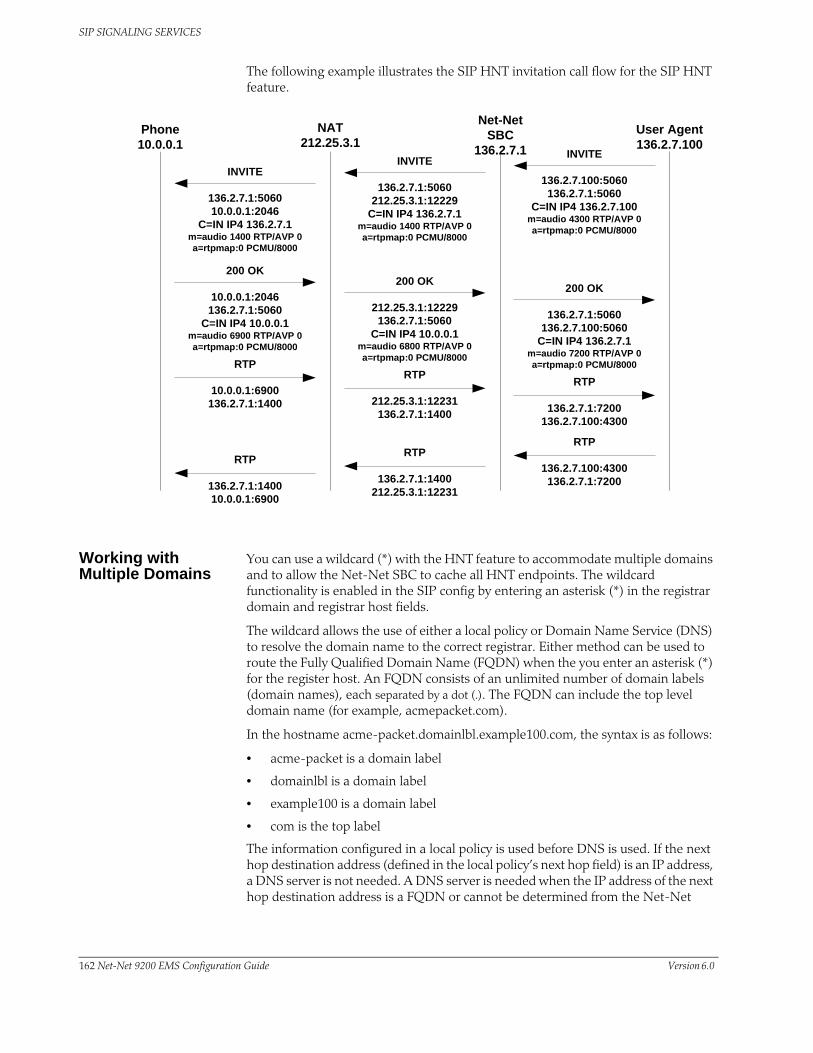
SIP SIGNALING SERVICES
The following example illustrates the SIP HNT invitation call flow for the SIP HNT feature.
Working with Multiple Domains
You can use a wildcard (*) with the HNT feature to accommodate multiple domains and to allow the Net-Net SBC to cache all HNT endpoints. The wildcard functionality is enabled in the SIP config by entering an asterisk (*) in the registrar domain and registrar host fields.
The wildcard allows the use of either a local policy or Domain Name Service (DNS) to resolve the domain name to the correct registrar. Either method can be used to route the Fully Qualified Domain Name (FQDN) when the you enter an asterisk (*) for the register host. An FQDN consists of an unlimited number of domain labels (domain names), each separated by a dot (.). The FQDN can include the top level domain name (for example, acmepacket.com).
In the hostname acme-packet.domainlbl.example100.com, the syntax is as follows:
• acme-packet is a domain label
• domainlbl is a domain label
• example100 is a domain label
• com is the top label
The information configured in a local policy is used before DNS is used. If the next hop destination address (defined in the local policy’s next hop field) is an IP address, a DNS server is not needed. A DNS server is needed when the IP address of the next hop destination address is a FQDN or cannot be determined from the Net-Net
INVITE
136.2.7.1:506010.0.0.1:2046
C=IN IP4 136.2.7.1m=audio 1400 RTP/AVP 0a=rtpmap:0 PCMU/8000
200 OK
10.0.0.1:2046136.2.7.1:5060
C=IN IP4 10.0.0.1m=audio 6900 RTP/AVP 0a=rtpmap:0 PCMU/8000
200 OK
212.25.3.1:12229136.2.7.1:5060
C=IN IP4 10.0.0.1m=audio 6800 RTP/AVP 0a=rtpmap:0 PCMU/8000
RTP
136.2.7.1:1400212.25.3.1:12231
RTP
10.0.0.1:6900136.2.7.1:1400
RTP
136.2.7.1:140010.0.0.1:6900
User Agent136.2.7.100
Phone10.0.0.1
200 OK
136.2.7.1:5060136.2.7.100:5060
C=IN IP4 136.2.7.1m=audio 7200 RTP/AVP 0a=rtpmap:0 PCMU/8000
RTP
136.2.7.100:4300136.2.7.1:7200
INVITE
136.2.7.1:5060212.25.3.1:12229
C=IN IP4 136.2.7.1m=audio 1400 RTP/AVP 0a=rtpmap:0 PCMU/8000
INVITE
136.2.7.100:5060136.2.7.1:5060
C=IN IP4 136.2.7.100m=audio 4300 RTP/AVP 0a=rtpmap:0 PCMU/8000
RTP
212.25.3.1:12231136.2.7.1:1400
RTP
136.2.7.1:7200136.2.7.100:4300
NAT212.25.3.1
Net-Net SBC
136.2.7.1
162 Net-Net 9200 EMS Configuration Guide Version 6.0

SIP SIGNALING SERVICES
SBC’s configuration. Even with a configured local policy, the next hop destination address might be an FQDN that requires a DNS lookup.
If the registrar host does not use the wildcard, the Net-Net SBC always uses the configured address. You can limit the number of endpoints that receive the HNT function. For example, you can use a non-wildcarded registrar domain field value (like acme.com) with a wildcarded registrar host field value.
HNT Configuration Overview
To configure SIP HNT NAT traversal, you need to configure both the SIP interface and the SIP config.
SIP HNT Single Domain Example
The following example shows values entered for the SIP config and SIP interface elements to configure SIP HNT for a single domain and registrar.
• SIP config
• SIP interface
SIP HNT Multiple Domain Example
The following example shows values entered for the SIP config and SIP interface elements to configure SIP HNT for a multiple domains and multiple registrars.
• SIP config
• SIP interface
Parameter Sample Value
registrar domain netnetsystem.com
registrar host 192.168.12.1
registrar port 5060
Parameter Sample Value
NAT traversal always
NAT interval 60
minimum registration expire 200
registration caching disabled
route to registrar enabled
Parameter Sample Value
registrar domain *
registrar host *
Parameter Sample Value
NAT traversal always
NAT interval 60
minimum registration expire 200
Version 6.0 Acme Packet, Inc. Technical Publications 163

SIP SIGNALING SERVICES
Configuring SIP Hosted NAT Traversal
This section describes how to configure SIP HNT on your Net-Net SBC from the Net-Net EMS.
1. Click Realms in the Net-Net EMS navigation tree.
The Realm table appears in the display pane.
2. Click the SIP realm you want to configure in the table and click Edit. The Edit Realm window appears.
3. Click the Services/Protocols tab. The Realm services table appears.
4. Click the name of the realm service you want to configure in the table and click Edit. The Edit SIP service window appears.
5. Click the SIP interface tab.
6. Scroll to the NAT traversal section.
NAT Traversal 1. Endpoints type supported by NAT traversal—Select the behavior of HNT for this SIP interface.
• none: Disables the HNT feature for SIP (default value)
• rport: SIP HNT function only applies to endpoints that include the rport parameter in the Via header and the sent-by of the topmost VIA matches the Contact-URI host address, both of which must be different from the received Layer 3 address.
• always: SIP HNT applies to requests when the sent-by of the topmost VIA matches the Contact-URI host address, both of which must be different from the received Layer 3 address. (Even when the rport parameter is not present.)
2. Endpoint to SD registration interval UDP (sec)—Set the expiration time in seconds for the Net-Net SBC’s cached registration entry for an HNT endpoint.
• minimum: zero (0) seconds (default value)
• maximum: 999999999 seconds
registration caching disabled
route to registrar enabled
Parameter Sample Value
164 Net-Net 9200 EMS Configuration Guide Version 6.0

SIP SIGNALING SERVICES
Acme Packet recommends setting the NAT interval to one-third of the NAT binding lifetime. A NAT binding lifetime is the network connection inactivity timeout. The value is configured (or hardwired) in the NAT device (firewall). This timer is used to prevent the NAT device from keeping an unused port open.
3. SD to registrar registration interval (sec)—Set the minimum registration expiration time in seconds for endpoints’ cached registration entries. The value you enter here sets the minimum registration expiration time in seconds for HNT registration caching.
• minimum: zero (0) seconds
• maximum: 999999999 seconds
This value defines the minimum expiration value the Net-Net SBC places in each REGISTER message it sends to the real registrar. In HNT, the Net-Net SBC caches the registration after receiving a response from the real registrar and sets the expiration time to the NAT interval value.
Some UAs might change the registration expiration value they use in subsequent requests to the value specified in this field. This change causes the Net-Net SBC to send frequent registrations on to the real registrar.
Registration Handling 1. Send transactions to registrar—Enable routing to the registrar to send all requests that match a cached registration to the destination defined for the registrar host; used when the Request-URI matches the registrar host value or the registrar domain value, not the Net-Net SBC’s address. Because the registrar host is the real registrar, it should send the requests back to the Net-Net SBC with the Net-Net SBC’s address in the Request-URI.
For example, you should enable routing to the registrar if your network uses a Net-Net SBC and needs requests to go through its service proxy, which is defined in the registrar host field.
2. Registration caching —Enable it for use with all UAs, not just those that are behind NATs. By default, this field is set to disabled. If enabled, the Net-Net SBC caches the Contact header in the UA’s REGISTER request when it is addressed to one of the following:
• Net-Net SBC
• registrar domain value
• registrar host value
The Net-Net SBC then generates a Contact header with the Net-Net SBC’s address as the host part of the URI and sends the REGISTER to the destination defined by the registrar host value.
Whether or not SIP HNT functionality is enabled affects the value of the user part of the URI sent in the Contact header:
• HNT enabled: the Net-Net SBC takes the user part of the URI in the From header of the request and appends a cookie to make the user unique. A
Version 6.0 Acme Packet, Inc. Technical Publications 165

SIP SIGNALING SERVICES
cookie is information that the server stores on the client side of a client-server communication so that the information can be used in the future.
• HNT disabled: the user part of the Contact header is taken from the URI in the From header and no cookie is appended. This is the default behavior of the Net-Net SBC.
When the registrar receives a request that matches the address-of-record (the To header in the REGISTER message), it sends the matching request to the Net-Net SBC, which is the Contact address. Then, the Net-Net SBC forwards the request to the Contact-URI it cached from the original REGISTER message.
3. SD to registrar registration interval (sec)—Enter the Net-Net SBC’s cached registration entry interval for a non-HNT endpoint in seconds. Enter the expiration time that you want the Net-Net SBC to use in the REGISTER response message sent back to the UA. The UA then refreshes its registration by sending another REGISTER message before that time expires.
• minimum: zero (0) seconds
A registration interval of zero causes the Net-Net SBC to pass back the expiration time set by and returned in the registration response from the registrar.
• maximum: 999999999 seconds
The default value is 3600 seconds (one hour). If the expiration time you set is less than the expiration time set by and returned from the real registrar, the Net-Net SBC responds to the refresh request directly rather than forwarding it to the registrar.
Note: With registration caching, there is no NAT; therefore, a short registration interval causes the UA to send excess REGISTER messages.
Although the registration interval applies to non-HNT registration cache entries, and the loosely related NAT interval applies to HNT registration cache entries, you can use the two in combination. Using a combination of the two means you can implement HNT and non-HNT architectures on the same Net-Net SBC. You can then define a longer interval time in the registration interval field to reduce the network traffic and load caused by excess REGISTER messages because there is no NAT binding to maintain.
4. Click Apply to continue.
166 Net-Net 9200 EMS Configuration Guide Version 6.0
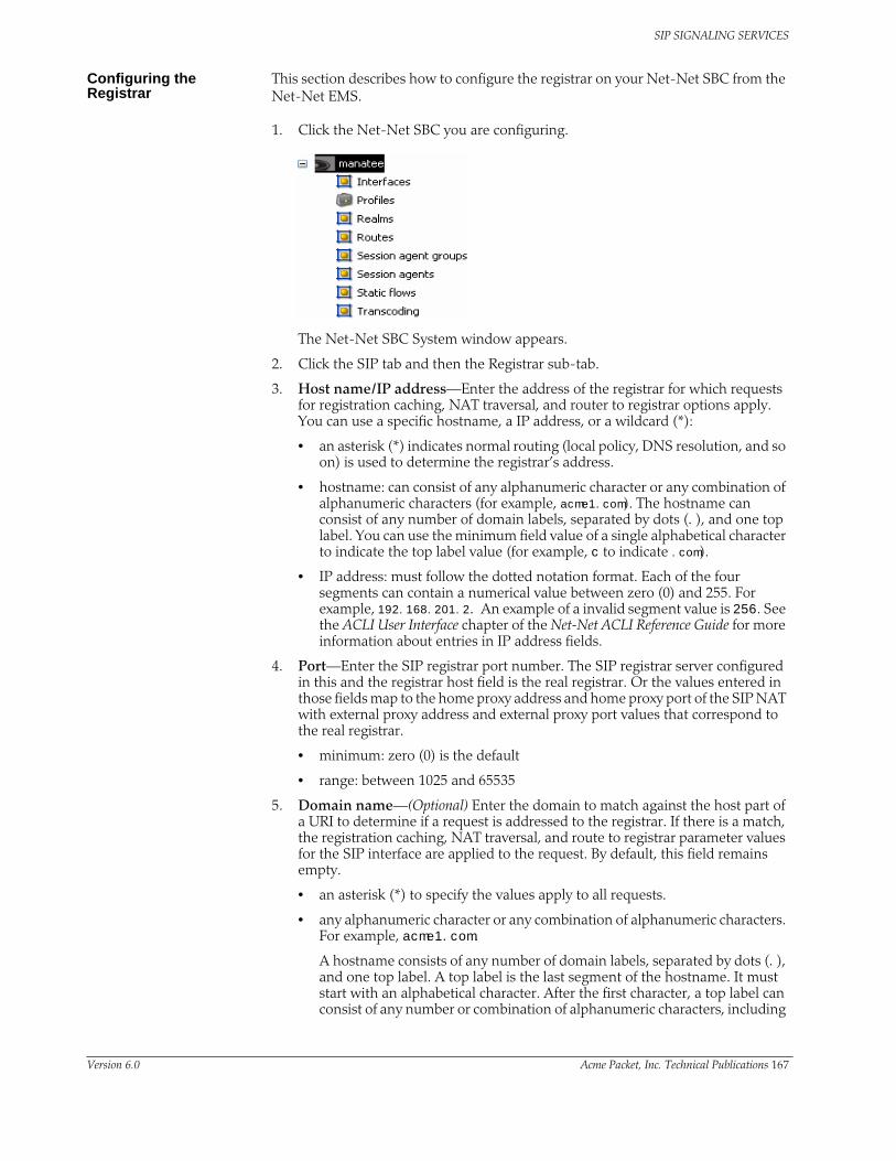
SIP SIGNALING SERVICES
Configuring the Registrar
This section describes how to configure the registrar on your Net-Net SBC from the Net-Net EMS.
1. Click the Net-Net SBC you are configuring.
The Net-Net SBC System window appears.
2. Click the SIP tab and then the Registrar sub-tab.
3. Host name/IP address—Enter the address of the registrar for which requests for registration caching, NAT traversal, and router to registrar options apply. You can use a specific hostname, a IP address, or a wildcard (*):
• an asterisk (*) indicates normal routing (local policy, DNS resolution, and so on) is used to determine the registrar’s address.
• hostname: can consist of any alphanumeric character or any combination of alphanumeric characters (for example, acme1.com). The hostname can consist of any number of domain labels, separated by dots (.), and one top label. You can use the minimum field value of a single alphabetical character to indicate the top label value (for example, c to indicate .com).
• IP address: must follow the dotted notation format. Each of the four segments can contain a numerical value between zero (0) and 255. For example, 192.168.201.2. An example of a invalid segment value is 256. See the ACLI User Interface chapter of the Net-Net ACLI Reference Guide for more information about entries in IP address fields.
4. Port—Enter the SIP registrar port number. The SIP registrar server configured in this and the registrar host field is the real registrar. Or the values entered in those fields map to the home proxy address and home proxy port of the SIP NAT with external proxy address and external proxy port values that correspond to the real registrar.
• minimum: zero (0) is the default
• range: between 1025 and 65535
5. Domain name—(Optional) Enter the domain to match against the host part of a URI to determine if a request is addressed to the registrar. If there is a match, the registration caching, NAT traversal, and route to registrar parameter values for the SIP interface are applied to the request. By default, this field remains empty.
• an asterisk (*) to specify the values apply to all requests.
• any alphanumeric character or any combination of alphanumeric characters. For example, acme1.com.
A hostname consists of any number of domain labels, separated by dots (.), and one top label. A top label is the last segment of the hostname. It must start with an alphabetical character. After the first character, a top label can consist of any number or combination of alphanumeric characters, including
Version 6.0 Acme Packet, Inc. Technical Publications 167

SIP SIGNALING SERVICES
those separated by dashes. The dash must be preceded and followed by alphanumeric characters. A single alphabetical character is the minimum requirement for a hostname field (for example, c to indicate .com).
When the REGISTER message’s Request-URI has an FQDN, it is matched against the registrar domain’s value to determine if the message needs to be forwarded to the registrar port on the registrar host. The registrar domain’s value is also used when route to registrar is set to enabled, to determine if a request needs to be forwarded to the registrar.
Only the right-hand part of the domain name in the Request-URI needs to match the registrar domain value. For example, acme3.acmepacket.com matches acmepacket.com. However, the entire domain label within the domain name must match. For example, the domain label “acme3.acmepacket.com” would not match “packet.com”.
6. Click Apply.
Configuring SIP Server RedundancyThis section explains how to configure SIP server redundancy. SIP server redundancy involves detecting that an upstream/downstream SIP signaling entity has failed, and adapting route policies dynamically to remove it as a potential destination.
Overview You establish SIP server redundancy by creating session agents, which are virtual representations of the SIP signaling entities. These agents are then collected into a session agent group, which is a logical collection of two or more session agents that behaves as a single aggregate entity. For more information about session agents and session agent groups, see the Session Routing and Load Balancing chapter in this guide.
Rather than direct signaling messages to a single session agent (IP), the signaling message is directed to a session agent group (SAG). The group will have a set distribution pattern: hunt, round robin, proportionally distributed, and so on. Signaling is spread amongst the agents using this chosen pattern.
You direct the signaling message by configuring a route policy, known as a local policy, which determines where SIP REQUESTS should be routed and/or forwarded. The values in the To and From headers in the SIP REQUEST are matched with the content of the local policy within the constraints set by the session agent’s previous hop value and SIP interface values such as the list of carriers.
To summarize, you need:
• Two or more session agents
• A session group containg those session agents
168 Net-Net 9200 EMS Configuration Guide Version 6.0

SIP SIGNALING SERVICES
• A local policy which directs traffic to the session agent group
Configuration Overview
You make a session agent group a target by using a local policy to select the next hop from the members of a session agent group. You need to set the replace URI field of the configured local policy to enabled; which causes NAT rules such as realm prefixing to be overridden. The replace URI field allows you to indicate whether the local policy’s value is used to replace the Request-URI in outgoing requests. This boolean field can be set to either enabled or disabled.
When the SIP NAT’s route home proxy field is set to forced, it forces the Request to be forwarded to the home proxy without using a local policy. When this option is set to either disabled or enabled and the Request-URI matches the external address of the SIP NAT, the local policy is used.
However, the local policy only replaces the Request-URI when the original Request-URI matches the Net-Net SBC’s IP address or hostname. This behavior is in accordance with that described in RFC 3261. The original Request-URI will be the home proxy address value (the home address of the SIP NAT into the backbone) and not the Net-Net SBC’s address.
Using strict routing, the Request-URI would be the next hop, but the message would also include a Route header with the original Request-URI. With loose routing, the Request-URI remains unchanged and the next hop value is added as the top Route header.
In some cases, the next hop field value must replace the Request-URI in the outgoing request, even if the original Request-URI is not the Net-Net SBC. To accomplish this, an option has been added to the local policy that causes the next hop value to be used as the Request-URI and prevents the addition of Route headers. This option is the replace uri value in the local policy.
The following table lists the policy attributes for the local policy:
Note: You should also define the ping method intervals for the session agents so that the Net-Net SBC can detect when the agents are back in service after failure.
For more information about local policy, see the Session Routing and Load Balancing (257) chapter in this guide.
Parameter Description
next hop IP address of your internal SIP proxy. This value corresponds to the IP address of the network interface associated with the SIP proxy.
realm Number of the port associated with the SIP port.
action Stores the transport protocol used for sending an receiving signaling messages associated with the SIP port.
Version 6.0 Acme Packet, Inc. Technical Publications 169

SIP SIGNALING SERVICES
Configuring SIP Server Redundancy
This section describes how to configure SIP server redundancy on your Net-Net SBC from the Net-Net EMS.
1. Click Routes located in the Net-Net EMS navigation tree. .
The Routes table appears in the Net-Net EMS display pane.
2. Select a route in the table you want to configure and click Edit.. The Route window appears.
3. Scroll to the Route polices area.
4. Highlight a route policy in the table and click Edit.
The Edit Route policy window appears. Scroll to Next hop.
5. Action—Choose replace-uri from the drop-down list.
The replace URI field allows you to indicate whether the local policy’s value is used to replace the Request-URI in outgoing requests.
6. Click OK.
7. Click Apply.
170 Net-Net 9200 EMS Configuration Guide Version 6.0

SIP SIGNALING SERVICES
Distributed Media ReleaseThis section explains how to configure distributed media release (DMR). SIP DMR lets you choose whether to include multi-system (multiple Net-Net SBCs) media release information in SIP signaling requests sent to a specific realm.
Overview The SIP DMR feature lets RTP/RTCP media be sent directly between SIP endpoints (for example, SIP phones or user agents) without going through a Net-Net SBC; even if the SIP signaling messages traverse multiple Net-Net SBCs. It encodes IP address and port information for the media streams described by the media, for example SDP.
With SIP DMR, the media realm and IP address and port information from the UA's SDP are encoded into SIP messages (either in the SIP header or in the SDP) as they enter the backbone network. The information is decoded by a Net-Net SBC from SIP messages that come from the backbone network. The decoded address and port information is put into the SDP sent the UAs in the access (private/customer) network.
This functionality lets the RTP/RTCP flow directly between the UAs in the access network without traversing the Net-Net SBCs and without passing into the backbone network. The media can then flow directly between the two SIP endpoints in the same network, if it is serviced by multiple Net-Net SBCs.
You can enable this feature on a per-realm basis and multiple realms can be supported.
Endpoint Locations You can configure the Net-Net SBC to release media when the source and destination of the call are in the same network, customer VPN, or customer LAN. In architectures that use DMR, the Net-Net SBC is only part of the media path for traffic that originates and terminates in different networks.
If configured to do so, the Net-Net SBC can release media:
• Between endpoints supported by a single Net-Net SBC
– In the same network/VPN
– In the same network behind the same NAT/firewall
• Between endpoints supported by multiple distributed Net-Net SBCs
– In the same network/VPN
Location of the Encoded Information
Encoded media release information can appear in three different places:
• SDP attribute
Media release data can be encoded into an SDP attribute in the SIP message body (for example, media-release=sdp;acme-media). The encoded data is placed into an acme-media attribute in the SDP:
a=acme-media:<encoded-media-interface-info>
• SIP header parameter
Media release data can be placed in a header parameter of a SIP header (for example, media-release=Contact;acme-media). The encoded data is placed into an acme-media parameter in the Contact header:
Contact: <sip:[email protected]>;acme-media=<encoded-media-interface-info>
Version 6.0 Acme Packet, Inc. Technical Publications 171

SIP SIGNALING SERVICES
• SIP header
Media release data can appear in a SIP header (for example, media-release=P-Media-Release). The encoded data is placed into a P-Media-Release header:
P-Media-Release: <encoded-media-interface-info>
Example: Distributed Media Release
The following example shows the network diagram for DMR in a multiple-site VPN environment supported by multiple, distributed Net-Net SBCs.
As shown in the network diagram, UA A and UA B register with the softswitch through Net-Net SBC A while UA C and UA D register with the softswitch through Net-Net SBC B. Without DMR, the media for calls between UA A/UA B and UA C/UA D is steered through both Net-Net SBC A and Net-Net SBC B.
With SIP DMR, the media realm and IP address and port information from the UA's Session Description Protocol (SDP) is encoded into SIP messages (either in the SIP header or in the SDP) as they enter the backbone (public/service provider) network. The information is decoded from SIP messages that come from the backbone network. The decoded address and port information is put into the SDP sent to the UAs in the access (private/customer) network. This functionality allows for the RTP/RTCP to flow directly between the UAs in the access network without traversing the Net-Net SBCs and without passing into the backbone network.
UA A
UA B
U A C
UA D
Softsw itch
B ackbone N etw ork
C ustom er A ccess N etw ork (VPN )
N et-N et SB C A
KeyPath of S IP registration w ithout m edia re lease
Path of S IP registration w ith m edia re leasePath of m edia flow w ith m edia re lease
Path of m edia w ithout m edia re lease
Point o f Presence 2(realm )
Point o f Presence 1(realm )
N et-N et SB C B
172 Net-Net 9200 EMS Configuration Guide Version 6.0

SIP SIGNALING SERVICES
Overview of SIP DMR Configuration
To configure SIP DMR:
1. Edit the SIP config element’s option field.
The media-release=”<header-name>[;<header-param>]” option defines how the SIP distributed media release feature encodes IP address and port information. If the media-release parameter is configured in the options field but no header is specified, the parameter value of P=Media-Release will be used. This parameter is optional and is not configured by default.
2. Enable SIP DMR for the entire realm by setting the realm config element’s msm release field to enabled.
The media IP address and port information is encoded into outgoing SIP messages and decoded from incoming SIP messages for all of the realms (in each realm-config element) with which the SIP distributed media release will be used. The realm names/identifiers must be identical.
Note: You can also use the realm config element’s mm in network field to release the media back to a connected network that has multiple realms. This field is not specific SIP distributed media release and it is not required for the SIP DMR to work. However, if this field is set to enabled and the ingress and egress realms are part of the same network interface, it lets the Net-Net SBC release the media.
Configuring Distributed Media Release
This section describes how to configure SIP distributed media release on your Net-Net SBC from the Net-Net EMS.
1. Click the Net-Net SBC you are configuring in the Net-Net EMS navigation tree.
The SBC System window appears in the Net-Net EMS display pane.
2. Click the SIP tab and then click the SIP options & tags subtab.
3. Click Options. The Options window appears.
4. Click media-release in the Available options list to select it.
Version 6.0 Acme Packet, Inc. Technical Publications 173

SIP SIGNALING SERVICES
5. Click to move the option to the opposite list. The option name appears along with a description in the lower part of the window.
6. media-release—Edit the textbox to append one of the following:
• SDP attribute, for example:
media-release=sdp;acme-media
• SIP header parameter, for example:
media-release=sdp;acme-media
• SIP header, for example:
media-release=P-Media-Release
7. Click OK to save your edits and close the SIP options window.
8. Click Apply.
174 Net-Net 9200 EMS Configuration Guide Version 6.0

SIP SIGNALING SERVICES
Configuring the Realm Configuration
This section describes how to configure SIP distributed media release on your Net-Net SBC from the Net-Net EMS.
1. Click Realms in the Net-Net EMS navigation tree.
The Realm table appears in the Net-Net EMS display pane.
2. Click a realm in the table to select it.
3. Click Edit. The Edit Realm window appears.
4. Scroll to the Release media peer-to-peer between endpoints section.
5. Within this realm serviced by different Net-Net systems (SIP-only)—Click the checkbox to enable DMR within this realm.
6. Click Apply.
Embedded Header (E911) SupportThis section explains how to configure embedded header support. The Net-Net SBC supports methods of extracting an embedded P-Asserted-Identity header from a contact header to support E911 when integrated with certain vendor’s systems. See RFC 3455 Private Header (P-Header) Extensions to the Session Initiation Protocol (SIP) for the 3rd-Generation Partnership Project (3GPP) for more information.
The embedded header support feature watches for a specified embedded header contained in a Contact header received in a 3XX message. When the specified embedded header is found, the full <header=value> pair is inserted as a unique header in a redirected INVITE message that exits the Net-Net SBC. If the outgoing INVITE message were to contain the specified header, regardless of the use of this feature, the value extracted from the 3XX message replaces the INVITE message’s specified header value.
If an incoming Contact header in a 3XX message looks like:
Contact: <ESRN@IPv4_Intrado_GW;user=phone?P-Asserted-Identity=%3Csip:+1-ESQK@IPv4_My_EAG;user=phone%3E>
Version 6.0 Acme Packet, Inc. Technical Publications 175

SIP SIGNALING SERVICES
when you configure your Net-Net SBC to parse for the embedded P-Asserted-Identity header to write as a unique header in the outgoing invite message, the outgoing INVITE and P-Asserted-Identity headers will look like:
INVITE SIP: ESRN@IPv4_Intrado_GW;user=phone
P-Asserted-Identity: +1-ESQK@IPv4_My_EAG;user=phone
Configuring Embedded Header Support
To configure embedded header support:
1. Click Session agents in the Net-Net EMS navigation tree.
The Session agent table appears in the display pane.
2. Click a SIP session agent you want to configure and click Edit. The Edit Session agent window appears in the display pane.
3. Click the SIP session agent routing and address translation tab. Scroll to Routing.
4. Incoming embedded headers to be converted to non-embedded headers—Click Add..
The Add Request URI header dialog box appears.
5. Enter the name of the header you want to convert from embedded to non-embedded.
6. Click OK. The Add Embedded headers dialog box closes and the header name appears in the Embedded header list.
7. Click Apply.
176 Net-Net 9200 EMS Configuration Guide Version 6.0

SIP SIGNALING SERVICES
Header and Parameter ManipulationThis section explains the SIP header and parameter manipulation feature, which lets the Net-Net SBC add, modify, and delete SIP headers and parts of SIP headers called SIP header elements. SIP header elements are the different subparts of the header, such as the header value, header parameter, URI parameter and so on (excluding the header name).
To enable the SIP header and parameter manipulation functionality, you create header manipulation rulesets in which you specify header manipulation rules, as well as optional header element rules that operate on specified header elements. You then apply the header manipulation ruleset as inbound or outbound for a session agent or SIP interface.
Header Manipulation Rules
Header manipulation rules operate on the header you specify when you configure the rule. A header manipulation rule can also be configured with a list of element rules, each of which would specify the actions you want performed for a given element of this header.
Header Element Rules
Header element rules perform operations on the elements of a header. Header elements include all subparts of a header; excluding the header name. For example, header value, header parameter, URI parameter, and so on.
About SIP Header and Parameter Manipulation
Using the SIP header manipulation ruleset, you can cause the Net-Net SBC to:
• Delete a header based on header name match.
• Delete a header based on header name match as well as header value match.
• Add a header.
• Modify the elements of a header (by configuring header element rules):
– Add an element to a header.
For example, add a parameter to a header or add a URI parameter to the URI in a header.
– Delete an element from a header.
For example, delete a parameter from a header or delete a URI parameter from the URI in a header.
– Modify an element of a header.
For example, replace a FQDN with an IP address in a header or replace the value of a parameter in the header.
– Delete a message body part
For example, delete the body part if the Content-Type is “application/ISUP”.
Role in Trunk Group URI Feature
SIP header and parameter manipulation plays a role in the trunk group URI feature. You need to set the new-value parameter to one of the trunk group values when configuring SIP header rules, if using this feature. (In addition you can configure session agents and session agents groups on the Net-Net SBC to insert trunk group URI parameters in the SIP contact header.
Version 6.0 Acme Packet, Inc. Technical Publications 177

SIP SIGNALING SERVICES
For all trunk group URI support, you must set the appropriate parameters in the SIP header manipulation configuration and in the session agent or session agent group configurations.
For trunk group URI support, the SIP header and parameter manipulation configuration tells the Net-Net SBC where and how to manipulate the SIP message to use originating (access) and terminating (egress) trunk group URI parameters.
See Trunk Group URIs (222) for more information about trunk group URIs.
Configuring Header and Parameter Manipulation
This section explains how to configure SIP header and parameter manipulation. First you create a SIP header manipulation ruleset, then the header manipulation rules and optional header element rules you want that ruleset to contain. You then configure a session agent or a SIP interface to use the SIP header and parameter manipulation ruleset in the inbound and outbound directions.
Creating SIP Header Manipulation Rule Sets
To configure SIP header manipulation ruleset:
1. Click Profiles in the Net-Net EMS navigation tree.
The Profiles window appears in the Net-Net EMS display pane.
2. Click the SIP manipulation tab.
3. Click Add. The Add SIP header manipulation dialog box appears.
4. SIP manipulation name—Enter a name for the new SIP header manipulation ruleset. For example:
5. Click OK to save your new ruleset. The new ruleset name appears at the top of the table.
178 Net-Net 9200 EMS Configuration Guide Version 6.0

SIP SIGNALING SERVICES
Adding Header Rules To add header rules:
1. Click the new ruleset name that you just created and click Edit. The Edit SIP header manipulation window appears.
2. Click Add. The Add Header rule dialog box appears.
3. Header rule name—Enter the name of the header rule.
4. Header name—Enter the name of the header to which this rule applies. (The name must match the SIP header name to which this rule applies.)
5. Click OK. The header rule appears in the table.
6. Click the header rule name in the table and click Edit. The Edit Header rule dialog box appears.
7. Action—Select the action you want applied to the header from the drop-down list. The following are valid options:
– add—Add a new header, if that header does not already exist.
– delete—Delete the header, if it exists.
Version 6.0 Acme Packet, Inc. Technical Publications 179
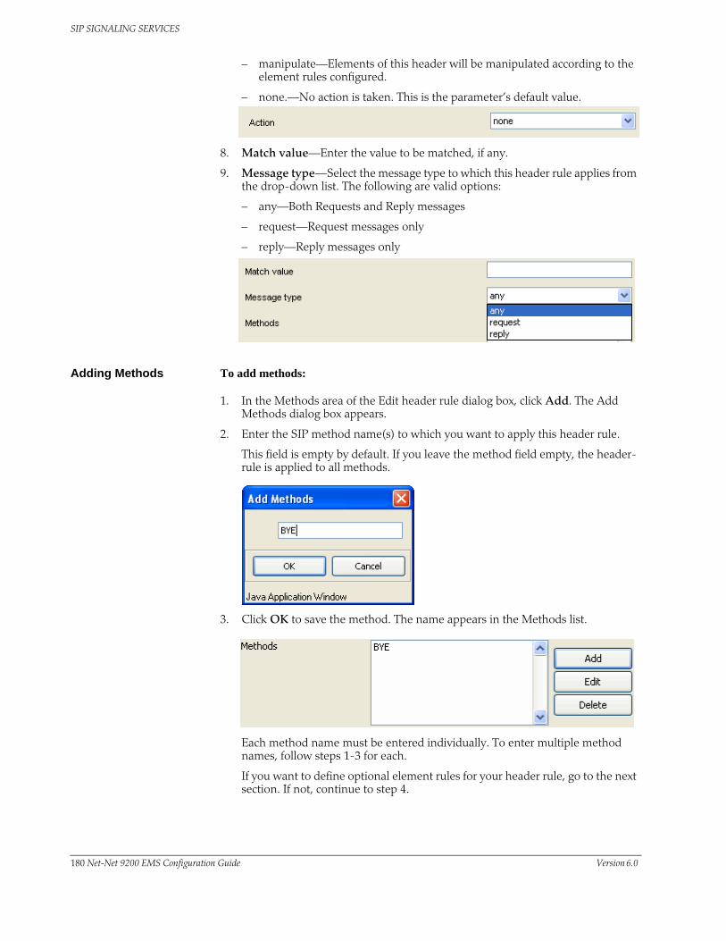
SIP SIGNALING SERVICES
– manipulate—Elements of this header will be manipulated according to the element rules configured.
– none.—No action is taken. This is the parameter’s default value.
8. Match value—Enter the value to be matched, if any.
9. Message type—Select the message type to which this header rule applies from the drop-down list. The following are valid options:
– any—Both Requests and Reply messages
– request—Request messages only
– reply—Reply messages only
Adding Methods To add methods:
1. In the Methods area of the Edit header rule dialog box, click Add. The Add Methods dialog box appears.
2. Enter the SIP method name(s) to which you want to apply this header rule.
This field is empty by default. If you leave the method field empty, the header-rule is applied to all methods.
3. Click OK to save the method. The name appears in the Methods list.
Each method name must be entered individually. To enter multiple method names, follow steps 1-3 for each.
If you want to define optional element rules for your header rule, go to the next section. If not, continue to step 4.
180 Net-Net 9200 EMS Configuration Guide Version 6.0

SIP SIGNALING SERVICES
4. Click Apply to save the header rule information. The header rule information appears in the Edit SIP header manipulation table.
5. Click Apply if you have finished defining your header rule.
Creating Element Rules
To create element rules:
1. In the Element rules area, click Add.
The Add Element rule dialog box appears.
2. Element rule name—Enter the name of the element to which this rule applies.
Note: The name you enter depends on the element type you enter in step 6. For uri-param, uri-user-param, and header-param it is the parameter name to be added, replaced, or deleted. For all other types, it serves to identify the element rule and any name can be used.
3. Click OK. The element rule appears in the table.
4. Click the element rule and click Edit. The Edit Element rule dialog box appears.
5. Parameter name—Enter the name you want to use for this rule set.
6. Type—Select the type of element on which to perform the action from the drop-down list. The options are
7. Action—Select the action you want applied to the element if there is a match value from the drop-down list. The options are:
8. Comparison type—Select the comparison type of comparison to be used for the match value. Select one of the following comparison types:
Option Description
header-value
Entire value of the header.
header-param
Parameter portion of the header.
uri-user User portion of the SIP URI.
uri-host Host portion of the SIP U.I
uri-port Port number portion of the SIP URI.
uri-param Parameter included in the SIP URI.
uri-header Header included in a request constructed from the URI.
uri-user-parameter
User parameter of the SIP URI.
Option Description
add Add a new element, if it does not already exist.
replace Replace the elements.
delete-element
Delete the specified element, if it exists. Based on the match value, if entered in step 6.
delete-header
Delete the specified header, if it exists.
Version 6.0 Acme Packet, Inc. Technical Publications 181

SIP SIGNALING SERVICES
• case-sensitive
• case-insensitive
• pattern-rule
9. Match value—Enter the value you want to match against the element value for an action to be performed.
10. Match value type—Select the type of value that needs to be matched for the action to be performed from the drop-down list. The options are:
11. New value—Enter the value for a new element or to replace a value for an existing element.You can enter an expression that includes a combination of absolute values, pre-defined parameters, and operators.
• Absolute values, with which you can use double quotes for clarity. You must escape all double quotes and back slashes that are part of an absolute value, and enclose the absolute value in double quotes.
For example:
“sip:”+$TRUNK_GROUP+”.”+$TRUNK_GROUP_CONTEXT
• Pre-defined parameters always start with a $. Valid pre-defined parameters are:
Option Description
IP Element value in the SIP message must be a valid IP address to be compared to the match-value field entry. If the match-value field is empty, any valid IP address is considered a match. If the element value is not a valid IP address, it is not considered a match.
FQDN Element value in the SIP message must be a valid FQDN to be compared to the match-value field entry. If the match-value field is empty, any valid FQDN is considered a match. If the element value is not a valid FQDN, it is not considered a match.
ANY Element value in the SIP message is compared with the match-value field entry. If the match-value field is empty, all values are considered a match.
Parameter Description
$ORIGINAL Original value of the element is used.
$LOCAL_IP IP address of the SIP interface on which the message was received for inbound manipulation; or sent on for outbound manipulation.
$REMOTE_IP IP address the message was received from for inbound manipulation; or being sent to for outbound manipulation.
$REMOTE_VIA_HOST Host from the top Via header of the message is used.
$TRUNK_GROUP Trunk group is used.
$TRUNK_GROUP_CONTEXT Trunk group context is used.
182 Net-Net 9200 EMS Configuration Guide Version 6.0

SIP SIGNALING SERVICES
• Operators are:
12. Click Apply to save your edits.
The new element rule appears in the Element rules table.
13. Click Apply to return to the Edit SIP manipulation ruleset window.
Operator Description
+ Append the value to the end. For example:“acme”+”packet”generates “acmepacket”
+^ Prepends the value. For example:“acme”+^”packet”generates “packetacme”
- Subtract at the end. For example:“112311”-”11”generates “1123”
-^ Subtract at the beginning. For example:“112311”-^”11”generates “2311”
Version 6.0 Acme Packet, Inc. Technical Publications 183

SIP SIGNALING SERVICES
Configuring a Session Agent
To configure a session agent:
1. Click Session agents in the Net-Net EMS navigation tree.
The Session agent table appears in the Net-Net EMS display pane.
2. Click the session agent in the table and click Edit. The Edit Session agent window appears in the display pane.
3. With the SIP session agent tab selected, scroll to SIP message handling.
4. Manipulation ruleset for inbound messages—Select the SIP header manipulation ruleset you want to apply to SIP packets in inbound messages.
5. Manipulation ruleset for outbound messages—Select the SIP header manipulation ruleset you want to apply to SIP packets in outbound messages.
6. Click Apply.
Configuring a SIP Interface
To configure a SIP interface:
1. Click Realms in the Net-Net EMS navigation tree.
The Realm table appears in the Net-Net EMS display pane.
2. Click the realm for which you want to configure the SIP interface in the table.
3. Click Edit. The Edit Realm window appears.
4. Click the Services/Protocols tab.
5. Click the realm service you want to configure and click Edit. The Edit SIP service window appears.
6. Scroll to Header manipulation.
184 Net-Net 9200 EMS Configuration Guide Version 6.0

SIP SIGNALING SERVICES
7. Manipulation ruleset for inbound messages—Select the SIP header manipulation ruleset you want to apply to SIP packets in inbound messages.
8. Manipulation ruleset for outbound messages—Select the SIP header manipulation ruleset you want to apply to SIP packets in outbound messages.
9. Click Apply.
SIP HMR (Header Manipulation Rules)SIP header manipulation can also be configured in a way that makes it possible to manipulate the headers in SIP messages both statically and dynamically. Using this feature, you can edit response headers or the Request-URI in a request, and change the status code or reason phrase in SIP responses.
Available in Net-Net OS Release 4.0 and later, Static SIP Header and Parameter Manipulation (236) allows you to set up rules in your Net-Net SBC configuration that remove and/or replace designated portions of specified SIP headers. SIP HMR allows you to set up dynamic header manipulation rules, meaning that the Net-Net SBC has complete control over alterations to the header value. More specifically:
• The Net-Net SBC can search header for dynamic content or patterns with the header value. It can search, for example, for all User parts of a URI that begin with 617 and end with 5555 (e.g., 617...5555).
• The Net-Net SBC can manipulate any part of a patterns match with any part of a SIP header. For example, 617 123 5555 can become 617 231 5555 or 508 123 0000, or any combination of those.
To provide dynamic header manipulation, the Net-Net SBC uses regular expressions to provide a high degree of flexibility for this feature. This allows you to search a specific URI when you do not know that value of the parameter, but want to use the matched parameter value as the header value. It also allows you to preserve matched sections of a pattern, and change what you want to change.
How It Works You can apply header manipulation to session agents, SIP interfaces, and realms. You do so by first setting up header manipulations rules, and then applying them in the configurations where they are needed. Within the header manipulation rules, there are sets of element rules that designate the actions that need to be performed on a given header.
Each header rule and each element rule (HMR) have a set of parameters that you configure to identify the header parts to be manipulated, and in what way the Net-Net SBC is to manipulate them. These parameters are explained in detail in the ACLI Instructions and Examples section for this feature, but the parameter that can take regular expression values is match-value. This is where you set groupings that you want to store, match against, and manipulate.
Generally, you set a header rule that will store what you want to match, and then you create subsequent rules that operate on this stored value. Because header rules and element rules are applied sequentially, it is key to note that a given rule performs
Version 6.0 Acme Packet, Inc. Technical Publications 185

SIP SIGNALING SERVICES
its operations on the results of all the rules that you have entered before it. For example, if you want to delete a portion of a SIP header, you would create Rule 1 that stores the value for the purpose of matching, and then create Rule 2 that would delete the portion of the header you want removed. This prevents removing data that might be used in the other header rules.
Given that you are using regular expression in this type of configuration, this tightly sequential application of rules means that you must be aware of the results to be yielded from the application of the regular expressions you enter. When you set a regular expression match value for the first rule that you enter, the Net-Net SBC takes the results of that match, and then a second rule might exist that tells the Net-Net SBC to use a new value if it the second rule’s match value finds a hit (and only 10 matches, 0-9, are permitted) for the results (yield) from applying the first rule.
Consider the example of the following regular expression entry made for a match-value parameter:‘Trunk(.+)’, which might be set as that match value in the first rule you configure. Given a SIP element rule called uri-param and the param-name tgid, it can yield two values:
• Grouping 0—The entire matching string (Trunk1)
• Grouping 1—The grouping (1)
In turn, these groupings can be referenced in an element rule by using this syntax:
$<header rule name >.$<element rule name.$<value>
Additional syntax options that can be used with this feature are:
• $headerName[‘[‘index’]’]
• $headerName[‘[‘index’]’][.$index]
• $headerName[‘[‘index’]’][.$elementName]
• $headerName[‘[‘index’]’][.$elementName][.$index]
Guidelines for Header and Element Rules
Header rules and element rules share these guidelines:
• References to groupings that do not exist result in an empty string.
• References to element rule names alone result in a Boolean condition of whether the expression matched or not.
• A maximum of ten matches are allowed for a regular expression. Match 0 (grouping 0) is always the match of the entire matching string; subsequent numbers are the results for other groups that match.
Precedence The Net-Net SBC applies SIP header rules in the order you have entered them. This guards against the Net-Net SBC removing data that might be used in the other header rules.
In addition to providing that guard, this ordering also provides you with ways to use manipulations strategically. For example, you might want to use two rules if you want to store the values of a regular expression. The first rule would store the value of a matched regular expression, and the second could delete the matched value.
Duplicate Header Names
If more than one header exists for the header name you have configured, the Net-Net SBC stores the value where it can be referenced with the optional syntax $<header rule name>[index]. Additional stored header values are indexed in the order in which they appear within the SIP message, and there is no limit to the index.
Possible index values are:
186 Net-Net 9200 EMS Configuration Guide Version 6.0

SIP SIGNALING SERVICES
• ~ — The Net-Net SBC references the first matching header
• * — The Net-Net SBC references all headers
• ^ — The Net-Net SBC references the last stored header in the header rule
Best Practices This section lists practices that Acme Packet recommends you follow for successful implementation of this feature.
• Define all storage rules first.
This recommendation is made because each subsequent header rule processes against the same SIP message, so each additional header rules works off of the results from the application of the rule that precedes it.
In general, you want to store values from the original SIP header rather than from the iteratively changed versions.
• Implement rules at the element rule rather than the header rule level.
Header rules should only be a container for element rules.
• When you are creating rules to edit a header, add additional element rules to modify a single header rather than try to create multiple header rules each with one element rule. That is, create multiple element rules within a header rule rather than creating multiple header rules.
• Do header rule name that is all capital letters; there are predefined rules that are used as macros, and they might conflict with a name that uses capital letters; e.g., $IP_ADDRESS.
About Regular Expressions
Two of the most fundamental ideas you need to know in order to work with regular expressions and with this feature are:
• Regular expressions are a way of creating strings to match other string values.
• You can use groupings in order to create stored values on which you can then operate.
To learn more about regex, you can visit the following Web site, which has information and tutorials that can help to get you started:http://www.regular-expressions.info/.
Many of the characters you can type on your keyboard are literal, ordinary characters—they present their actual value in the pattern. Some characters have special meaning, however, and they instruct the regex function (or engine which
Version 6.0 Acme Packet, Inc. Technical Publications 187

SIP SIGNALING SERVICES
interprets the expressions) to treat the characters in designated ways. The following table outlines these “special characters” or “metacharacters.”
Character Name Description
. dot Matches any one character, including a space; it will match one character, but there must be one character to match.
Literally a . (dot) when bracketed ([]), or placed next to a \ (backslash).
* star/asterisk Matches one or more preceding character (0, 1, or any number), bracketed carrier class, or group in parentheses. Used for quantification.
Typically used with a . (dot) in the format .* to indicate that a match for any character, 0 or more times.
Literally an * (asterisk) when bracketed ([]).
+ plus Matches one or more of the preceding character, bracketed carrier class, or group in parentheses. Used for quantification.
Literally a + (plus sign) when bracketed ([]).
| bar/vertical bar/pipe Matches anything to the left or to the right; the bar separates the alternatives. Both sides are not always tried; if the left does not match, only then is the right attempted. Used for alternation.
{ left brace Begins an interval range, ended with } (right brace) to match; identifies how many times the previous singles character or group in parentheses must repeat.
Interval ranges are entered as minimum and maximums ({minimum,maximum}) where the character/group must appear a minimum of times up to the maximum. You can also use these character to set magnitude, or exactly the number of times a character must appear; you can set this, for example, as the minimum value without the maximum ({minimum,}).
? question mark Signifies that the preceding character or group in parentheses is optional; the character or group can appear not at all or one time.
^ caret Acts as an anchor to represent the beginning of a string.
$ dollar sign Acts as an anchor to represent the end of a string.
188 Net-Net 9200 EMS Configuration Guide Version 6.0

SIP SIGNALING SERVICES
Configuring SIP HMR
1. Click Profiles in the Net-Net EMS navigation tree.
The Profiles window appears in the Net-Net EMS display pane.
2. Click the SIP manipulation tab.
3. Select the SIP manipulation you want to configure and click Edit. The Edit SIP header manipulation window appears.
4. Click Add. The Add Header rule dialog box appears.
5. Header rule name—Enter the unique identifier for this SIP HMR. There is no default for this value.
[ left bracket Acts as the start of a bracketed character class, ended with the ] (right bracket). A character class is a list of character options; one and only on of the characters in the bracketed class must appear for a match. A - (dash) in between two character enclosed by brackets designates a range; for example [a-z] is the character range of the lower case twenty-six letters of the alphabet.
Note that the ] (right bracket) ends a bracketed character class unless it sits directly next to the [ (left bracket) or the ^ (caret); in those two cases, it is the literal character.
( left parenthesis Creates a grouping when used with the ) (right parenthesis). Groupings have two functions:• They separate pattern strings so that a
whole string can have special characters within it as if it were a single character.
• They allow the designated pattern to be stored and referenced later (so that other operations can be performed on it).
Character Name Description
Version 6.0 Acme Packet, Inc. Technical Publications 189
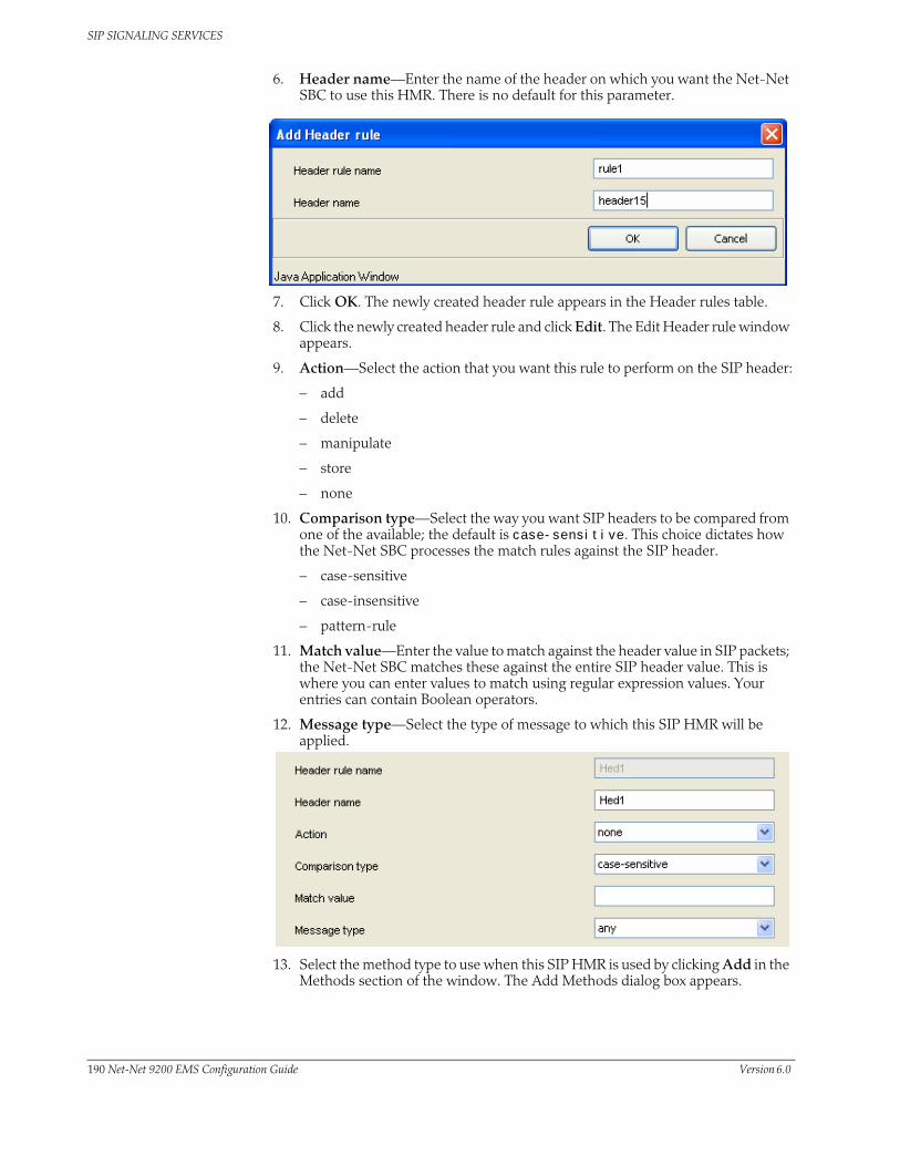
SIP SIGNALING SERVICES
6. Header name—Enter the name of the header on which you want the Net-Net SBC to use this HMR. There is no default for this parameter.
7. Click OK. The newly created header rule appears in the Header rules table.
8. Click the newly created header rule and click Edit. The Edit Header rule window appears.
9. Action—Select the action that you want this rule to perform on the SIP header:
– add
– delete
– manipulate
– store
– none
10. Comparison type—Select the way you want SIP headers to be compared from one of the available; the default is case-sensitive. This choice dictates how the Net-Net SBC processes the match rules against the SIP header.
– case-sensitive
– case-insensitive
– pattern-rule
11. Match value—Enter the value to match against the header value in SIP packets; the Net-Net SBC matches these against the entire SIP header value. This is where you can enter values to match using regular expression values. Your entries can contain Boolean operators.
12. Message type—Select the type of message to which this SIP HMR will be applied.
13. Select the method type to use when this SIP HMR is used by clicking Add in the Methods section of the window. The Add Methods dialog box appears.
190 Net-Net 9200 EMS Configuration Guide Version 6.0

SIP SIGNALING SERVICES
14. Add Methods—Enter the method you want to add.
15. Click OK.
16. When the action parameter is set to add or manipulate, enter the new value that you want to substitute for the entire header value. This is where you can set stored regular expression values for the Net-Net SBC to use when it adds or manipulates SIP headers.
Configuring SIP Header Manipulation Element Rules
Element rules are a subset of the SIP header manipulation rules and are applied at the element type level rather than at the entire header value.
To configure SIP Header Manipulation Element Rules:
1. Click Add in the Element rules section of the Edit Header rule window. The Add Element rule dialog box appears.
2. Element rule name—Enter the name of the element rule you want to add.
3. Click OK. The newly created element rule appears in the Element rules table.
4. Click the newly created element rule and click Edit. The Edit Element rule window appears.
5. Parameter name—Enter the SIP header parameter/element on which you want the Net-Net SBC to use this rule. There is no default for this parameter.
6. Type—Select the type of parameter to which this element rule will be applied. There is no default for this parameter, and you can use values such as: header-value, header-param-name, header-param, uri-display, uri-user, uri-user-param, uri-host, uri-port, uri-param-name, uri-param, uri-header-name, or uri-header.
To configure HMR so that there is impact only on the status-line; the value will be used for matching according to the comparison-type:
• status-code—Designates the status code of the response line; accepts any string, but during the manipulation process only recognizes the range from 100 to 699.
• reason-phrase—Designates the reason of the response line; accepts any string.
Version 6.0 Acme Packet, Inc. Technical Publications 191

SIP SIGNALING SERVICES
7. Action—Enter the action that you want this rule to perform on the SIP header parameter/element:
– add
– delete
– manipulate
– store
– none
8. Comparison type—Enter the way that you want SIP headers to be compared from one of the available; the default is case-sensitive. This choice dictates how the Net-Net SBC processes the match rules against the SIP header parameter/element.
– case-sensitive
– case-insensitive
– pattern-rule
9. Match value—Enter the value to match against the header value in SIP packets; the Net-Net SBC matches these against the value of the parameter/element. This is where you can enter values to match using regular expression values, or stored pattern matches. Your entries can contain Boolean operators.
10. Match value type—Enter the value type that you want to match when this rule is applied; you can set this to IP, FQDN, or ANY, and the default is ANY.
11. New value—When the action parameter is set to add or to manipulate, enter the new value that you want to substitute for the entire header value. This is where you can set stored regular expression values for the Net-Net SBC to use when it adds or manipulates parameters/elements.
12. Click Apply.
192 Net-Net 9200 EMS Configuration Guide Version 6.0

SIP SIGNALING SERVICES
Setting the Response Code Block
To enable SIP HMR for status-line manipulation, you need to set an option in SIP interface configuration that keeps the Net-Net SBC from sending the response you designate.
To set the response code block:
1. Click Realms in the Net-Net EMS navigation tree. .
The Realm window appears in the Net-Net EMS display pane.
2. Select the realm to which you want to set response code block and click Edit. The Edit Realm window appears.
3. Click the Services/Protocols tab.
4. Select the realm service you want to configure and click Edit.
5. Click the Options button. The Options window appears.
6. Click the dropResponse option from Available options.
Version 6.0 Acme Packet, Inc. Technical Publications 193

SIP SIGNALING SERVICES
7. Click to move the option to the opposite list. The option name appears along with a description in the lower part of the window.
8. Click OK.
194 Net-Net 9200 EMS Configuration Guide Version 6.0

SIP SIGNALING SERVICES
Applying Multiple SIP Header Manipulation RulesetsYou can create multiple SIP header manipulation rulesets in order to:
• Apply multiple inbound and outbound manipulations rules to a SIP message
• Provision the order in which the Net-Net SBC applies manipulation rules
The Action parameter in the header rules configuration now takes the value sip-manip. When you set the parameter to sip-manip, you then configure the New value parameter with the name of a SIP manipulation rule that you want to invoke. The values for the Match value, Comparison type, and Methods parameters for invoked rules are all supported. This means that the manipulation defined by the rules identified in the New value parameter are carried out when the values for the Match value, Comparison type, and Methods parameters are true.
The relationship between manipulation rules and manipulation rulesets is created once you load your configuration, meaning that the order in which you enter them does not matter. It also means that the Net-Net SBC cannot dynamically perform validation as you enter rules, so you should confirm your manipulation rules contain neither invalid nor circular references. Invalid references are those that point to SIP manipulation rules that do not exist, and circular references are those that create endless loops of manipulation rules being carried out over and over. If you load a configuration exhibiting either of these issues, the Net-Net SBC forces the Action value for the rule to none and the rule will not be used.
Configuring Multiple SIP HMR Sets
To configure multiple SIP header manipulation rulesets:
1. Click Profiles in the Net-Net navigation tree.
The Profiles window appears in the Net-Net display pane.
2. Click the SIP manipulation tab.
3. Click the SIP header rule and click Edit. The Edit SIP header manipulation window appears.
4. Click the ruleset name in the Header rules table and click Edit. The Edit Header rule window appears.
5. Action—Choose the sip-manip value from the drop-down list. This value then invokes the rule identified in the New value parameter.
Version 6.0 Acme Packet, Inc. Technical Publications 195
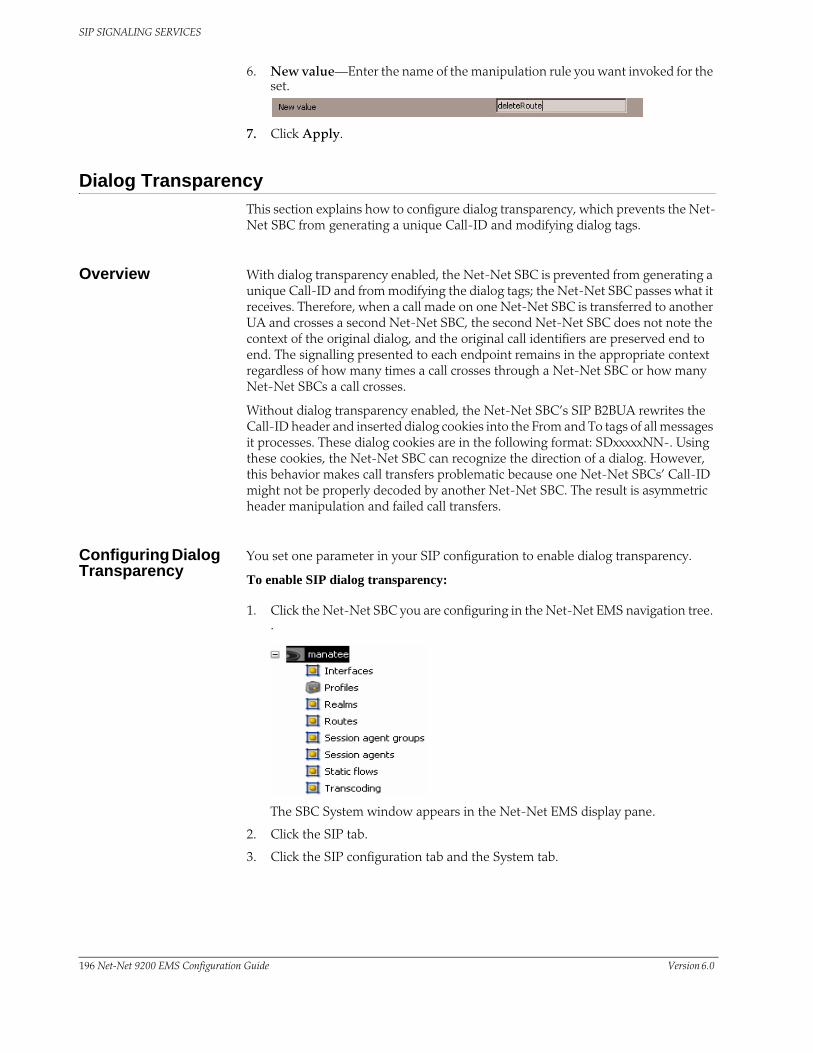
SIP SIGNALING SERVICES
6. New value—Enter the name of the manipulation rule you want invoked for the set.
7. Click Apply.
Dialog TransparencyThis section explains how to configure dialog transparency, which prevents the Net-Net SBC from generating a unique Call-ID and modifying dialog tags.
Overview With dialog transparency enabled, the Net-Net SBC is prevented from generating a unique Call-ID and from modifying the dialog tags; the Net-Net SBC passes what it receives. Therefore, when a call made on one Net-Net SBC is transferred to another UA and crosses a second Net-Net SBC, the second Net-Net SBC does not note the context of the original dialog, and the original call identifiers are preserved end to end. The signalling presented to each endpoint remains in the appropriate context regardless of how many times a call crosses through a Net-Net SBC or how many Net-Net SBCs a call crosses.
Without dialog transparency enabled, the Net-Net SBC’s SIP B2BUA rewrites the Call-ID header and inserted dialog cookies into the From and To tags of all messages it processes. These dialog cookies are in the following format: SDxxxxxNN-. Using these cookies, the Net-Net SBC can recognize the direction of a dialog. However, this behavior makes call transfers problematic because one Net-Net SBCs’ Call-ID might not be properly decoded by another Net-Net SBC. The result is asymmetric header manipulation and failed call transfers.
Configuring Dialog Transparency
You set one parameter in your SIP configuration to enable dialog transparency.
To enable SIP dialog transparency:
1. Click the Net-Net SBC you are configuring in the Net-Net EMS navigation tree. .
The SBC System window appears in the Net-Net EMS display pane.
2. Click the SIP tab.
3. Click the SIP configuration tab and the System tab.
196 Net-Net 9200 EMS Configuration Guide Version 6.0

SIP SIGNALING SERVICES
4. Preserve Call-IDs and tags—Click the checkbox to activate the dialog transparency feature. When enabled, the Net-Net SBC does not generate unique Call IDs and does not modify dialog tags.
5. Click Apply.
Route Header RemovalThis section explains how to enable the Net-Net SBC to disregard and strip all SIP Route headers. You set an option in a SIP interface configuration to strip all Route headers for SIP requests coming from this interface.
When the Net-Net SBC with this option configured receives an INVITE from an interface, it removes the route headers. However, although it removes the headers, the Net-Net SBC maintains backward compatibility with RFC 2543 nodes. To do so, it normalizes the request to an RFC 3261 loose routing form before it removes the headers.
Configuring Route Header Removal
To configure SIP route header removal:
1. Click Realms in the Net-Net EMS navigation tree.
The Realm table appears in the Net -Net EMS display pane.
2. Click a SIP realm in the table to select it.
3. Click Edit. The Edit Realm window appears.
4. Click the Services/Protocols tab. The Realm services table appears.
5. Click the name of the realm to which you want to apply SIP route header removal in the table.
6. Click Edit. The Edit SIP service window appears.
7. With the SIP interface tab selected, scroll to the Options in SIP service section and click Options. The Options window appears.
Version 6.0 Acme Packet, Inc. Technical Publications 197

SIP SIGNALING SERVICES
8. Click strip-route-headers in the Available options list to select it.
9. Click to move the option to the Selected options list. The option name appears along with a description in the lower part of the window.
10. Click OK to continue.
198 Net-Net 9200 EMS Configuration Guide Version 6.0

SIP SIGNALING SERVICES
Via TransparencyThis section explains the inbound Via header transparency feature, which enables the Net-Net SBC to insert its Via header on top of the top-most Via header received from user equipment (UE). It then forwards it on to the IP Multimedia Subsystem (IMS) core with the original Via header now located as the bottom-most Via header.
The Net-Net SBC still replaces the Contact and other header addresses with its own, and does not pass on the core’s Via headers in outbound requests.
This feature is targeted for the Telecoms & Internet converged Services & Protocols for Advanced Networks (TISPAN) with SIP hosted NAT traversal support. It works with SIP NAT bridged, local-policy routed, and non-SIP NAT configurations, regardless of registration handling.
How it Works Some equipment acts as Proxy-CSCF (P-CSCF) and Serving-CSCF (S-CSCF) nodes, with the Net-Net SBC is located between the equipment and user endpoints. The equipment needs to see the each user endpoint’s original Via header in order to perform some implicit authentication, admission, and control functions in a TISPAN-compliant model.
You enable Via header transparency on the access SIP interface or a session agent. Received Via headers are saved for inclusion in requests going out another interface or session agent that does not have the parameter set, in other words, the core side. For any received SIP message where the inbound previous hop interface was enabled for Via header transparency, the Net-Net SBC adds its own Via header as it forwards it, and it also copies the received top-most Via as the new bottom-most Via, if the outbound next hop interface/session agent is not enabled for Via header transparency. The Net-Net SBC also adds a received= parameter to the copied Via header, per the SIP RFC 3261.
Any message received from an interface without Via header transparency enabled, does not have the received Via header copied over to any other direction.
For HNT, where the original top-most (and only) Via header from a UE is a private/false address, the SD should still copy that false address into the core-side, and the received= parameter will contain the real Layer-3 addressing.
Configuring Via Transparency
You can configure SIP Via header transparency for the access SIP interface using Net-Net EMS.
To configure SIP Via header transparency for an access interface:
1. Click Realms in the Net-Net EMS navigation tree. The Realm table appears in the Net-Net EMS display pane.
2. Click a SIP realm in the table to select it.
3. Click Edit. The Edit Realm window appears.
4. Click the Services/Protocols tab. The Realm services table appears.
5. Click the name of the realm to which you want to apply SIP route header removal in the table.
6. Click Edit. The Edit SIP service window appears.
7. With the SIP interface tab selected, scroll to Options in realm and click Options.
Version 6.0 Acme Packet, Inc. Technical Publications 199
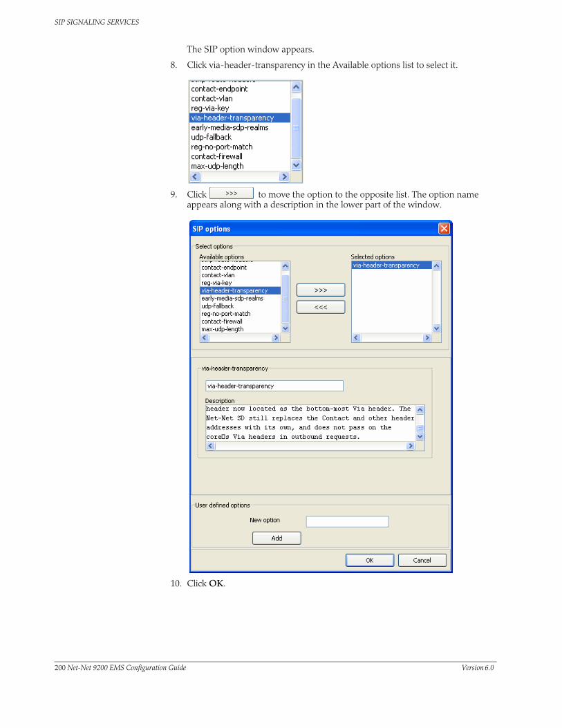
SIP SIGNALING SERVICES
The SIP option window appears.
8. Click via-header-transparency in the Available options list to select it.
9. Click to move the option to the opposite list. The option name appears along with a description in the lower part of the window.
10. Click OK.
200 Net-Net 9200 EMS Configuration Guide Version 6.0

SIP SIGNALING SERVICES
Symmetric LatchingSymmetric latching, or forced HNT, ensures that symmetric RTP/RTCP is used for a SIP endpoint. Symmetric RTP/RTCP means that the IP address and port pair used by an outbound RTP/RTCP flow is reused for the inbound flow. The IP address and port are learned when the initial RTP/RTCP flow is received by the Net-Net SBC. The flow's source address and port are latched onto and used as the destination for the RTP/RTCP sourced by the other side of the call. The IP address and port in the c line and m line respectively in the SDP message are ignored.
If your network is configured with nested realms in order to separate signalling from media, make sure that the symmetric latching feature is enabled on the signaling realm.
Note: This description is applicable to RTCP only when you also enable the HNT RTCP option in the media-manager configuration. Do not enable symmetric latching on core-facing interfaces.
Configuring Symmetric Latching
To configure symmetric latching:
1. Click Realms in the Net-Net EMS navigation tree. The Realm table appears in the Net-Net EMS display pane.
2. Click a SIP realm in the table to select it.
3. Click Edit. The Edit Realm window appears.
4. Symmetric latching—Click the checkbox to enable symmetric latching.
5. Click Apply.
Configuring RTCP Symmetric Latching
1. Click the SBC you want to configure in the Net-Net EMS navigation tree. The Net-Net SBC system window appears.
2. Click the Media control tab.
3. RTC support for NAT traversal—Click the checkbox to enable HNT RTCP.
4. Click Apply.
Version 6.0 Acme Packet, Inc. Technical Publications 201

SIP SIGNALING SERVICES
Number NormalizationThis section explains the SIP number normalization feature that applies to the SIP To URI. Number normalization includes add, delete, and replace string functions that result in consistent number formats.
How it Works Number normalization applies to the SIP To URI. It occurs on ingress traffic, prior to the generation of accounting records or local policy lookups. RADIUS CDR attributes are populated with the normalized numbers. Local policy matching is based on the normalized numbers.
Terminology The following terminology is used in the descriptions contained in the next sections.
• X is any digit having the value 0 through 9
• N is any digit having the value 2 through 9
• 0/1 is a digit having the value of either 0 or 1
• NXX is a form of Numbering Plan Area (NPA).
• CC is a 1, 2, or 3 digit country code used in international dialing
• NN is a national number that can be a four to fourteen digit national number used in international dialing, where the combination of CC+NN is a 7 to 15 digit number.
• + symbol in E.164 indicates that an international prefix is required
• E.164 numbers are globally unique, language independent identifiers for resources on Public Telecommunication Networks that can support many different services and protocols.
• N11 number is any of the three-digit dialing codes in the form N11 used to connect users to special services, where N is a digit between 2 and 9
Calls from IP Endpoints
The Net-Net SBC uses the following number normalization rules:
• North American Numbering Plan (NANP) calls: where a number with the format 1NPANXXXXXX is received, the Net-Net SBC adds a plus sign (+) as a prefix to the NANP number. The Net-Net SBC also adds the string ;user=phone after the host IP address in the SIP URI. For example:
sip:+1NPANXXXXXX@ipaddr;user=phone
• International NWZ1 calls: Net-Net SBC receives an international call with the format 011CCNN. The Net-Net SBC deletes the 011 prefix and adds a plus sign (+) as a prefix to CC+NN; and also adds the string ;user=phone after the host IP address in the SIP URI. For example:
sip:+CCNN@ipaddr;user=phone
• Private number calls: when a private number with the format nxxxx (where n=2 through 9) is received, no number normalization is applied by the Net-Net SBC.
• Calls to numbers such as N11, 0-, 0+, 00-, and 01+: the Net-Net SBC adds ;phone-context=+1 after the number and also adds the string ;user=phone after the host IP address in the SIP URI. For example:
sip:N11;phone-context=+1@ipaddr;user=phone
sip:01CCNN;phone-context=+1@ipaddr;user=phone
202 Net-Net 9200 EMS Configuration Guide Version 6.0

SIP SIGNALING SERVICES
• Calls with numbers that are already normalized are not modified by the Net-Net SBC.
Calls from IP Peer Network
For calls received from external peer networks, the Net-Net SBC uses the following number normalization rules:
• Global numbers such as NANP and international E.164 numbers should have already been normalized. If not, the Net-Net SBC applies the same number normalization rules listed in the prior section.
• Calls to numbers such as N11, 0-, 0+, 00-, and 01+: the Net-Net SBC adds ;phone-context=+1 after the number and also adds the string ;user=phone (if absent) after the host IP address in the SIP URI.
Configuring Number Normalization
You can configure SIP number normalization for the realm and session agent using Net-Net EMS.
Realm To configure SIP number normalization for a realm:
1. Click Realms in the Net-Net EMS navigation tree. The Realm table appears in the Net-Net EMS display pane.
2. Click a SIP realm in the table to select it.
3. Click Edit. The Edit Realm window appears.
4. Scroll to the Options section and click Options. The Options window appears.
5. Click number-normalization in the Available options list to select it.
Version 6.0 Acme Packet, Inc. Technical Publications 203

SIP SIGNALING SERVICES
6. Click to move the option to the Selected options list. The option name appears along with a description in the lower part of the window.
7. Click OK to continue.
Configuring Number Normalization for a Session Agent
To configure SIP number normalization for a session agent:
1. Click Session agents in the Net-Net EMS navigation tree. The Session agent table appears in the display pane.
2. Click the SIP session agent to which you want to apply number normalization in the table to select it.
3. Click Edit. The Edit Session agent window appears.
4. Scroll to SIP message handling.
5. For the SIP options for this SA parameter, click Options. The Options window appears.
204 Net-Net 9200 EMS Configuration Guide Version 6.0
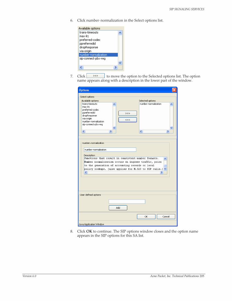
SIP SIGNALING SERVICES
6. Click number-normalization in the Select options list.
7. Click to move the option to the Selected options list. The option name appears along with a description in the lower part of the window.
8. Click OK to continue. The SIP options window closes and the option name appears in the SIP options for this SA list.
Version 6.0 Acme Packet, Inc. Technical Publications 205
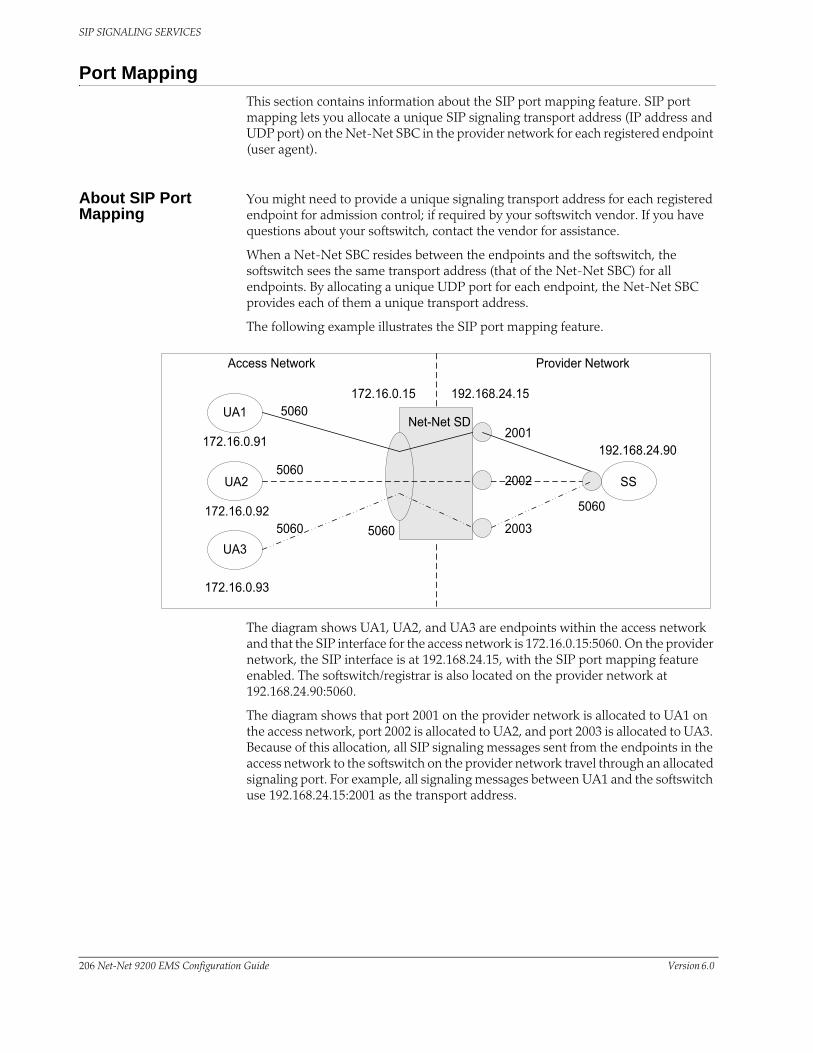
SIP SIGNALING SERVICES
Port MappingThis section contains information about the SIP port mapping feature. SIP port mapping lets you allocate a unique SIP signaling transport address (IP address and UDP port) on the Net-Net SBC in the provider network for each registered endpoint (user agent).
About SIP Port Mapping
You might need to provide a unique signaling transport address for each registered endpoint for admission control; if required by your softswitch vendor. If you have questions about your softswitch, contact the vendor for assistance.
When a Net-Net SBC resides between the endpoints and the softswitch, the softswitch sees the same transport address (that of the Net-Net SBC) for all endpoints. By allocating a unique UDP port for each endpoint, the Net-Net SBC provides each of them a unique transport address.
The following example illustrates the SIP port mapping feature.
The diagram shows UA1, UA2, and UA3 are endpoints within the access network and that the SIP interface for the access network is 172.16.0.15:5060. On the provider network, the SIP interface is at 192.168.24.15, with the SIP port mapping feature enabled. The softswitch/registrar is also located on the provider network at 192.168.24.90:5060.
The diagram shows that port 2001 on the provider network is allocated to UA1 on the access network, port 2002 is allocated to UA2, and port 2003 is allocated to UA3. Because of this allocation, all SIP signaling messages sent from the endpoints in the access network to the softswitch on the provider network travel through an allocated signaling port. For example, all signaling messages between UA1 and the softswitch use 192.168.24.15:2001 as the transport address.
206 Net-Net 9200 EMS Configuration Guide Version 6.0

SIP SIGNALING SERVICES
How SIP Port Mapping Works
The Net-Net SBC allocates SIP port mapping (signaling) ports during a REGISTER request that has registration caching applied. When you define a range of signaling ports for the SIP interface, you create a pool of signaling ports that can be allocated during the REGISTER request.
The Net-Net SBC allocates a signaling port from the pool when it creates the registration cache entry for a Contact in a REGISTER request. It allocates a separate signaling port for each unique Contact URI from the access side. The registration cache Contact entry contains the mapping between the Contact URI in the access/endpoint realm (the UA-Contact) and the Contact URI in the registrar/softswitch realm (the SD-Contact).
The SD-Contact is the allocated signaling port. The signaling port gets returned to the pool when the Contact is removed from the registration cache. The removal can occur when the cache entry expires; or when the endpoint sends a REGISTER request to explicitly remove the Contact from the registrar. When a signaling port returns to the pool it gets placed at the end of pool list; in a least-recently-used allocation method for signaling ports.
When the Net-Net SBC forwards the REGISTER request to the softswitch, it replaces the UA-Contact with SD-Contact. For example, if UA1 sends a REGISTER request with a Contact URI of sip:[email protected]:5060, it is replaced with sip:192.168.24.15:2001 when the REGISTER request is forwarded to the registrar.
The same translation occurs when UA1 sends that same URI in the Contact header of other SIP messages. SIP requests addressed to the allocated signaling transport address (SD-Contact) are translated and forwarded to the registered endpoint contact address (UA-Contact).
Note: The maximum number of registered endpoints cannot exceed the number of signaling ports available. If no signaling ports are available for a new registration, the REGISTER request receives a 503 response.
The Net-Net SBC still processes requests received on the configured SIP port address. Requests sent into the registrar/softswitch realm that are not associated with a registered user will use the configured SIP port address.
About NAT Table ACL Entries
To enable SIP signaling messages to reach the host processor, the Net-Net SBC adds NAT table ACL entries for each SIP interface. With UDP without SIP port mapping applied, it adds a single ACL entry for each SIP port in the SIP interface configuration. For example:
untrusted entries:
intf:vlan source-ip/mask:port/mask dest-ip/mask:port/mask prot type index
0/0:0 0.0.0.0 172.16.1.15:5060 UDP static 10
0/3:0 0.0.0.0 192.168.24.15:5060 UDP static 16
0/1:0 0.0.0.0 192.168.50.25:5060 UDP static 17
Version 6.0 Acme Packet, Inc. Technical Publications 207

SIP SIGNALING SERVICES
Using SIP Port Mapping
When you use SIP port mapping, one or more ACL entries are added to the NAT table to enable the range of ports defined. The NAT table does not support the specification of port ranges. However, it does support masking the port to enable ranges that fall on bit boundaries. For example, an entry for 192.168.24.15:4096/12 defines the port range of 4096 through 8191.
The algorithm for determining the set of ACLs for the port map range balances the need to represent the range as closely as possible, with the need to minimize the number of ACL entries. For example, a range of 30000 through 39999 would result in the following set of ACLs.
untrusted entries:
intf:vlan source-ip/mask:port/mask dest-ip/mask:port/mask prot type index
0/3:0 0.0.0.0 192.168.24.15:30000/4 UDP static 13
0/3:0 0.0.0.0 192.168.24.15:32768/4 UDP static 14
0/3:0 0.0.0.0 192.168.24.15:36864/4 UDP static 15
However, the first entry actually enables ports 28672 though 32767 and the last entry allows port 36864 through 40959. If SIP messages are received on ports outside the configured range (28672 through 29999 or 40000 through 40959 in this case), they are ignored.
Acme Packet recommends you use port map ranges that fall on bit boundaries to ensure the fewest possible ACL entries are created and only the configured ports are allowed by the ACLs. For example, a range of 32768 to 49151 provides for 16,384 signaling ports in a single ACL entry (192.168.24.15:32768/2).
Note: If the ACLs added for the port map range do not include the SIP port configured in the SIP interface; the normal SIP ACL entry for the SIP port is also added.
Dynamic Configuration
Dynamic configuration of SIP port mapping can cause disruption in service for existing registration cache entries; depending on the changes made to the defined port map range. If the range of mapping ports is reduced, it is possible that SIP signaling messages from the registrar/softswitch realm will no longer be sent to the host processor because of the changes in the NAT Table ACL entries.
When the range of mapping ports is changed, any signaling ports in the free signaling port pool not allocated to a registration cache entry are removed from the pool. When an allocated signaling port that is no longer part of the defined mapping port range is released, it is not returned to the pool of free steering ports.
The administrator is warned when the changed configuration is activated after the port map range of a SIP interface has been changed.
208 Net-Net 9200 EMS Configuration Guide Version 6.0
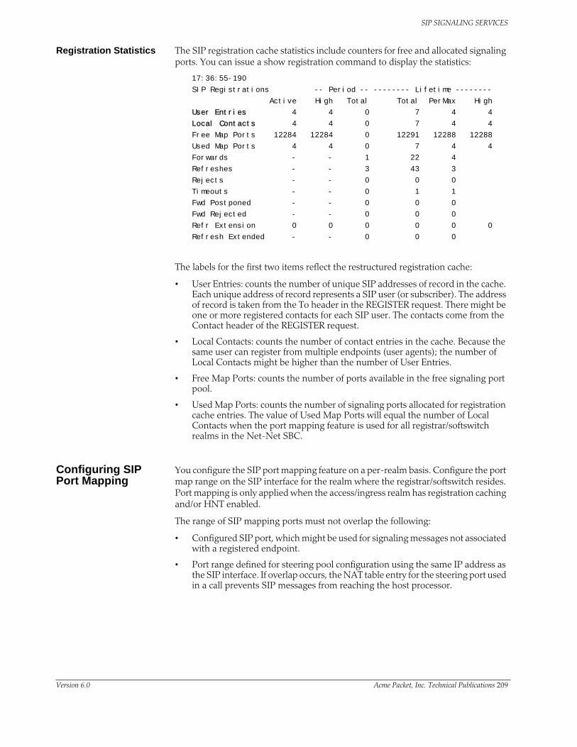
SIP SIGNALING SERVICES
Registration Statistics The SIP registration cache statistics include counters for free and allocated signaling ports. You can issue a show registration command to display the statistics:
17:36:55-190
SIP Registrations -- Period -- -------- Lifetime --------
Active High Total Total PerMax High
User Entries 4 4 0 7 4 4
Local Contacts 4 4 0 7 4 4
Free Map Ports 12284 12284 0 12291 12288 12288
Used Map Ports 4 4 0 7 4 4
Forwards - - 1 22 4
Refreshes - - 3 43 3
Rejects - - 0 0 0
Timeouts - - 0 1 1
Fwd Postponed - - 0 0 0
Fwd Rejected - - 0 0 0
Refr Extension 0 0 0 0 0 0
Refresh Extended - - 0 0 0
The labels for the first two items reflect the restructured registration cache:
• User Entries: counts the number of unique SIP addresses of record in the cache. Each unique address of record represents a SIP user (or subscriber). The address of record is taken from the To header in the REGISTER request. There might be one or more registered contacts for each SIP user. The contacts come from the Contact header of the REGISTER request.
• Local Contacts: counts the number of contact entries in the cache. Because the same user can register from multiple endpoints (user agents); the number of Local Contacts might be higher than the number of User Entries.
• Free Map Ports: counts the number of ports available in the free signaling port pool.
• Used Map Ports: counts the number of signaling ports allocated for registration cache entries. The value of Used Map Ports will equal the number of Local Contacts when the port mapping feature is used for all registrar/softswitch realms in the Net-Net SBC.
Configuring SIP Port Mapping
You configure the SIP port mapping feature on a per-realm basis. Configure the port map range on the SIP interface for the realm where the registrar/softswitch resides. Port mapping is only applied when the access/ingress realm has registration caching and/or HNT enabled.
The range of SIP mapping ports must not overlap the following:
• Configured SIP port, which might be used for signaling messages not associated with a registered endpoint.
• Port range defined for steering pool configuration using the same IP address as the SIP interface. If overlap occurs, the NAT table entry for the steering port used in a call prevents SIP messages from reaching the host processor.
Version 6.0 Acme Packet, Inc. Technical Publications 209

SIP SIGNALING SERVICES
To configure SIP port mapping:
1. Click Realms in the Net-Net EMS navigation tree.
The Realm table appears in the Net-Net EMS display pane.
2. Click a SIP realm in the table to select it.
3. Click Edit. The Edit Realm window appears.
4. Click the Services/Protocols tab. The Realm Services table appears.
5. Click the SIP realm in the table and click Edit. The Edit SIP service window appears.
6. With the SIP interface tab selected, scroll to Port mapping.
7. Start port—Enter the starting port for the range of SIP ports available for SIP port mapping. The valid range is 1025 through 65535. If you set the value to zero (0), SIP port mapping is disabled.
8. End port—Enter the ending port for the range of SIP ports available for SIP port mapping. The valid range is 1025 through 65535. If you set the value to zero (0), SIP port mapping is disabled.
9. Click Apply.
Configurable Route RecursionWhen the Net-Net SBC routes SIP requests from a UAC to a UAS, it might determine that there are multiple routes to try based on a matching local policy. The Net-Net SBC recurses through the list of routes in a specific order according to your configuration and the quality of the match. There are other scenarios when a UAS replies with a 3xx Redirect response to the Net-Net SBC, the 3xx response can include multiple Contacts to which the request should be forwarded in a specific order. In both cases, the Net-Net SBC needs to recurse through a list of targets.
When the Net-Net SBC receives a non-successful (or non-6xx response) final response from the UAS, and there are multiple targets for the original request, the Net-Net SBC will forward the request to the next target and wait for a response. While the process of forwarding the request to multiple targets as explained in the previous paragraph is called serial forking, and the process of forwarding the request
210 Net-Net 9200 EMS Configuration Guide Version 6.0
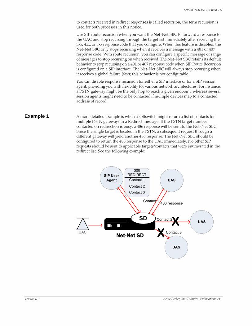
SIP SIGNALING SERVICES
to contacts received in redirect responses is called recursion, the term recursion is used for both processes in this notice.
Use SIP route recursion when you want the Net-Net SBC to forward a response to the UAC and stop recursing through the target list immediately after receiving the 3xx, 4xx, or 5xx response code that you configure. When this feature is disabled, the Net-Net SBC only stops recursing when it receives a message with a 401 or 407 response code. With route recursion, you can configure a specific message or range of messages to stop recursing on when received. The Net-Net SBC retains its default behavior to stop recursing on a 401 or 407 response code when SIP Route Recursion is configured on a SIP interface. The Net-Net SBC will always stop recursing when it receives a global failure (6xx); this behavior is not configurable.
You can disable response recursion for either a SIP interface or for a SIP session agent, providing you with flexibility for various network architectures. For instance, a PSTN gateway might be the only hop to reach a given endpoint, whereas several session agents might need to be contacted if multiple devices map to a contacted address of record.
Example 1 A more detailed example is when a softswitch might return a list of contacts for multiple PSTN gateways in a Redirect message. If the PSTN target number contacted on redirection is busy, a 486 response will be sent to the Net-Net SBC. Since the single target is located in the PSTN, a subsequent request through a different gateway will yield another 486 response. The Net-Net SBC should be configured to return the 486 response to the UAC immediately. No other SIP requests should be sent to applicable targets/contacts that were enumerated in the redirect list. See the following example:
Version 6.0 Acme Packet, Inc. Technical Publications 211

SIP SIGNALING SERVICES
Example 2 The Net-Net SBC might determine from a local policy lookup that several routes are applicable for forwarding a SIP message. The Net-Net SBC will try each route in turn, but the SIP response recursion disable feature can be implemented to stop the route recursion when a configured responses message is received by the Net-Net SBC. See the following example:
There are a few conditions on the parameter used to configure response recursion:
• SIP Route Recursion is configurable for either the SIP interface or session agent.• 401 and 407 are preconfigured for all configured SIP interfaces. They are not
configured for session agents.• The format is a comma-separated list of response codes or response code
ranges: 404, 484-486.• Only response codes that fall within the 3xx, 4xx, and 5xx range may be
specified.
Configuring Route Recursion
You can configure a session agent or a SIP interface for SIP route recursion using Net-Net EMS.
To configure a session agent for SIP route recursion:
1. Click Session agents in the Net-Net EMS navigation tree.
The Session agent table appears in the Net-Net EMS display pane.
2. Click the SIP session agent to which you want to apply route recursion in the table and click Edit.
The Edit Session agent window appears in the display pane.
212 Net-Net 9200 EMS Configuration Guide Version 6.0

SIP SIGNALING SERVICES
3. Click the SIP session agent constraints tab.
4. In the List of response codes for recursion area, click Add. The SIP Response codes window appears.
5. SIP response code—Enter the response code value. You can enter a single response code or response code range; or a comma-delimited list of response codes or response code ranges.
6. Click OK to close the dialog box. The response code value appears in the list. For example:
7. Click Apply.
Configuring a SIP Interface for SIP Route Recursion
To configure a SIP interface for SIP route recursion:
1. Click Realms in the Net-Net EMS navigation pane. The Realm table appears in the Net-Net EMS display pane.
2. Click the realm in the table and click Edit. The Edit Realm window appears.
3. Click the Services/Protocols tab. The Realm Services table appears.
4. Click the realm in the table and click Edit. The Edit SIP service window appears.
5. Scroll to List or response code for recursion and click Add. The SIP response codes window appears.
6. Response code—Enter the response code value. You can enter a single response code or response code range; or a comma-delimited list of response codes or response code ranges.
Version 6.0 Acme Packet, Inc. Technical Publications 213

SIP SIGNALING SERVICES
7. Click OK to close the dialog box. The response code value appears in the list. For example:
8. Click Apply.
Event Package InteroperabilityService providers often deploy a Net-Net SBC on the border of an access network, where it sits between the SIP endpoints (user agents) and the service provider’s application server. The application server and the user agents sometimes use various SIP event packages to exchange and maintain state information. The SUBSCRIBE and NOTIFY methods are used to establish subscriptions to the event packages and to report state changes to the subscribing entity.
The SIP global contact option addresses interoperability in the Dialog and Presence event packages that are used in hosted PBX and IP Centrex offerings. State information is passed in the message body of a NOTIFY request; this message body is encoded in an XML format described by the Content-Type header. The Net-Net SBC needs to update certain fields in the body to account for dialog mapping and SIP NAT functionality between the access and service provider realms. Often the subscriptions are established using URIs learned from Contact headers in the user agent registrations or dialog establishment (INVITE/SUBSCRIBE). For this, a Net-Net SBC requires a Contact URI that is usable and routable outside of an existing dialog.
The SIP global contact option enables persistent URIs in the Contact headers inserted into outgoing SIP messages. If this option is not used, URIs placed in the Contact header of outgoing messages are only valid within the context of the dialog to which the message is associated.
RFCs associated with this feature are:
• A. B. Roach, “Session Initiation Protocol (SIP)-Specific Event Notification,” RFC 3265, June 2002
• J. Rosenberg, “A Presence Event Package for the Session Initiation Protocol (SIP),” RFC 3856, August 2004
• J. Rosenberg, et al. “Data Format for Presence Using XML,” http://www.iptel.org/info/players/ietf/presence/outdated/draft-rosenberg-impp-pidf-00.txt, Work In Progress (expired), June 2000
• J.Rosenberg, H. Schulzrinne, R. Mahy, “An INVITE Initiated Dialog Event Package for the Session Initiation Protocol (SIP),” draft-ietf-sipping-dialog-package-06.txt, Work In Progress, April 2005
• H. Sugano, et al., “Presence Information Data Format (PIDF),” RFC 3863, August 2004
214 Net-Net 9200 EMS Configuration Guide Version 6.0

SIP SIGNALING SERVICES
Configuring Event Package Interoperability
You can configure SIP event package interoperability using Net-Net EMS.
To configure SIP event package interoperability:
1. Click the Net-Net SBC you are configuring in the Net-Net EMS navigation tree.
The SBC System window appears in the Net-Net EMS display pane.
2. Click the SIP tab.
3. Click the SIP config tab and the Options and tags sub-tab.
4. Click Options. The Options window appears.
5. Click global-contact in the Available options list to select it.
Version 6.0 Acme Packet, Inc. Technical Publications 215

SIP SIGNALING SERVICES
6. Click to move the option to the opposite list. The option name appears along with a description in the lower part of the window.
7. Click OK to save your edits and close the Options window.
8. Click Apply.
216 Net-Net 9200 EMS Configuration Guide Version 6.0
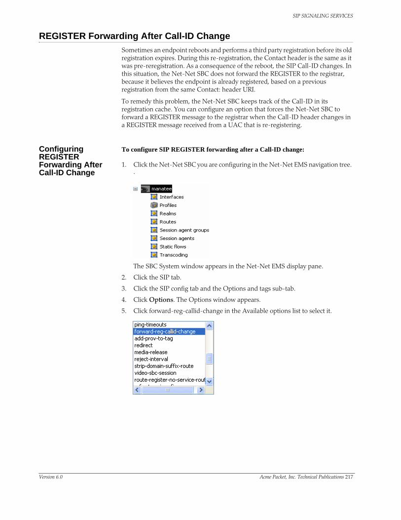
SIP SIGNALING SERVICES
REGISTER Forwarding After Call-ID ChangeSometimes an endpoint reboots and performs a third party registration before its old registration expires. During this re-registration, the Contact header is the same as it was pre-reregistration. As a consequence of the reboot, the SIP Call-ID changes. In this situation, the Net-Net SBC does not forward the REGISTER to the registrar, because it believes the endpoint is already registered, based on a previous registration from the same Contact: header URI.
To remedy this problem, the Net-Net SBC keeps track of the Call-ID in its registration cache. You can configure an option that forces the Net-Net SBC to forward a REGISTER message to the registrar when the Call-ID header changes in a REGISTER message received from a UAC that is re-registering.
Configuring REGISTER Forwarding After Call-ID Change
To configure SIP REGISTER forwarding after a Call-ID change:
1. Click the Net-Net SBC you are configuring in the Net-Net EMS navigation tree. .
The SBC System window appears in the Net-Net EMS display pane.
2. Click the SIP tab.
3. Click the SIP config tab and the Options and tags sub-tab.
4. Click Options. The Options window appears.
5. Click forward-reg-callid-change in the Available options list to select it.
Version 6.0 Acme Packet, Inc. Technical Publications 217

SIP SIGNALING SERVICES
6. Click to move the option to the opposite list. The option name appears along with a description in the lower part of the window.
7. Click OK to save your edits and close the Options window.
8. Click Apply.
218 Net-Net 9200 EMS Configuration Guide Version 6.0
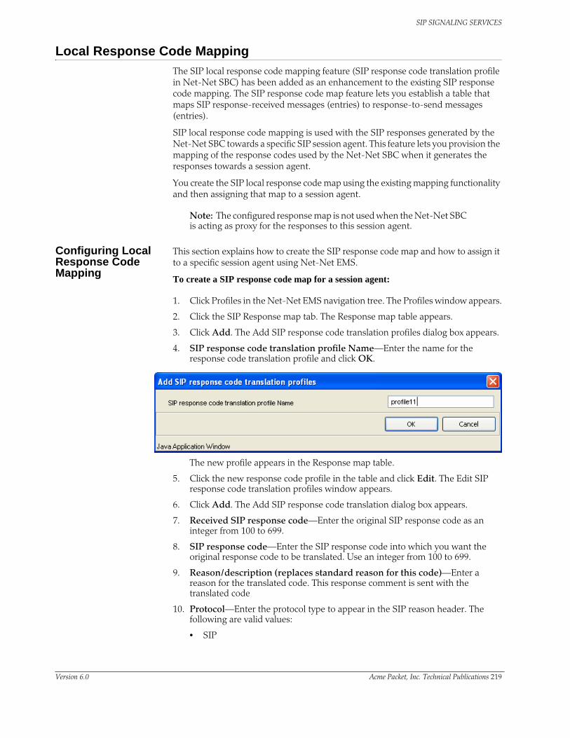
SIP SIGNALING SERVICES
Local Response Code MappingThe SIP local response code mapping feature (SIP response code translation profile in Net-Net SBC) has been added as an enhancement to the existing SIP response code mapping. The SIP response code map feature lets you establish a table that maps SIP response-received messages (entries) to response-to-send messages (entries).
SIP local response code mapping is used with the SIP responses generated by the Net-Net SBC towards a specific SIP session agent. This feature lets you provision the mapping of the response codes used by the Net-Net SBC when it generates the responses towards a session agent.
You create the SIP local response code map using the existing mapping functionality and then assigning that map to a session agent.
Note: The configured response map is not used when the Net-Net SBC is acting as proxy for the responses to this session agent.
Configuring Local Response Code Mapping
This section explains how to create the SIP response code map and how to assign it to a specific session agent using Net-Net EMS.
To create a SIP response code map for a session agent:
1. Click Profiles in the Net-Net EMS navigation tree. The Profiles window appears.
2. Click the SIP Response map tab. The Response map table appears.
3. Click Add. The Add SIP response code translation profiles dialog box appears.
4. SIP response code translation profile Name—Enter the name for the response code translation profile and click OK.
The new profile appears in the Response map table.
5. Click the new response code profile in the table and click Edit. The Edit SIP response code translation profiles window appears.
6. Click Add. The Add SIP response code translation dialog box appears.
7. Received SIP response code—Enter the original SIP response code as an integer from 100 to 699.
8. SIP response code—Enter the SIP response code into which you want the original response code to be translated. Use an integer from 100 to 699.
9. Reason/description (replaces standard reason for this code)—Enter a reason for the translated code. This response comment is sent with the translated code
10. Protocol—Enter the protocol type to appear in the SIP reason header. The following are valid values:
• SIP
Version 6.0 Acme Packet, Inc. Technical Publications 219

SIP SIGNALING SERVICES
• q850
• preemption.
11. Cause—Enter the protocol cause value to appear after the “cause” label of the SIP reason header.
12. Text—Enter the text to appear after the “text=” label in the SIP reason header.
13. Click OK to save your edits and close the dialog box. The values appear in the Response code translation table in the Edit SIP response code translation profiles window.
14. Click Apply to save the values and close the Edit SIP response code translation profiles window. You return to the Response map tab displaying the Response map table.
Assigning the Response Code Map to a Session Agent
To assign a response code map
1. Click Session agents in the Net-Net EMS navigation tree. The Session agent table appears in the display pane.
2. Click the SIP session agent that you want to configure in the table and click Edit. The Edit Session agent window appears.
3. Scroll to SIP message handling.
4. Local response code translation profile—Choose the local response code translation profile from the drop-down list.
5. Click Apply.
220 Net-Net 9200 EMS Configuration Guide Version 6.0

SIP SIGNALING SERVICES
Session Agent Ping Message FormattingYou can configure the user portion of the From: header, the To: header, and the Request-URI in the ping-type message that the Net-Net SBC sends to a session agent. This feature is required for interoperability with certain E911 servers.
In the following example of a session agent ping-type message, you can set the user portion of the Request-URI (the text bob in the OPTIONS method line) and the user portion of the From: header (the text bob in the From: header) to the same new value. You can also set the user portion of the To: header (the text anna in the To: header) to its own new value.
OPTIONS sip:[email protected] SIP/2.0
From: UA1 <sip:[email protected]>
To: NUT <sip:[email protected]>
Call-ID: [email protected]
CSeq: 1 OPTIONS
Contact: <sip:[email protected]>
Accept: application/sdp
Content-Length: 0
If you do not enable this feature, the session agent ping-type message will contain the text “ping” in all cases.
Configuring Session Agent Ping Message Formatting
To configure session agent ping message formatting:
1. Click Session agents in the Net-Net EMS navigation tree. The Session agent table appears in the display pane.
2. Click the SIP session agent for which you want to use session agent ping message formatting in the table and click Edit. The Edit Session agent window appears in the display pane.
3. Scroll to SIP message handling.
4. User part to be used in PING To header—Enter the user name.
5. User part to be used in PING From header—Enter the user name and user URI.
6. Click Apply.
Version 6.0 Acme Packet, Inc. Technical Publications 221

SIP SIGNALING SERVICES
SIP PPI—PAI ConversionThe SIP PAI stripping offers the ability to covert P-Preferred-Identity and P-Asserted-Identity (PAI) headers so that service providers can ensure an extra measure of security against malicious users pretending to be legitimate users.
Configuring SIP PPI—PAI Conversion
This section explains how to configure SIP PPI—PAI conversion.
1. Click Realms in the Net-Net EMS navigation tree. The Realm table appears in the display pane.
2. Select the realm you want to configure and click Edit. The Edit realm window appears.
3. Select the Services/Protocols tab.
4. Select the realm service you want to configure and click Edit. The Edit SIP service window appears.
5. Preferred/Asserted identity conversion mode—Select the conversion mode you want to use from the Preferred/Asserted identity conversion mode drop-down list. The following are valid values for this parameter.
• none
• trusted
• always
• remove
Trunk Group URIsThe Net-Net SBC can enable the capabilities related to trunk groups that are described in this section (applicable for SIP and IWF signaling services). This implementation follows the IPTEL draft “Representing Trunk Groups in Tel/SIP Uniform Resource Identifiers (URIs)” (draft-ietf-iptel-trunk-group-06.txt), and also supports more customized approaches.
• For a typical access call flow scenario, when the calling party’s call arrives at the Net-Net SBC, the Net-Net SBC formulates a SIP INVITE message that it sends to a softswitch. The Net-Net SBC supports a URI contact parameter in the SIP request message so that service providers need to be able to:
• Determine from where the Net-Net SBC received the call
• Signal information about the originating gateway from a Net-Net SBC to a softswitch (for example, an incoming trunk group or a SIP gateway to a Net-Net SBC)
• Support of signaling of routing information to the Net-Net SBC from network routing elements like softswitches. This information tells the Net-Net SBC what egress route (or outgoing trunk groups) it should choose for terminating next
222 Net-Net 9200 EMS Configuration Guide Version 6.0

SIP SIGNALING SERVICES
hops/gateways. For this purpose, SIP URI parameters in the Request-URI are defined. Additional URI parameters include the network context to identify the network in which the originating or terminating gateway resides.
• Especially important for large business applications, this feature can free Net-Net SBC resources by reducing the number of local policy, session agent, and session agent group configurations. By enabling the trunk group URI feature, the Net-Net SBC instead uses a routing scheme based on signaled SIP URI information.
Terminology The following IPTEL terms are used in the descriptions of and instructions for how to configure this feature:
• Trunk—In a network, a communication path connecting two switching systems used in the establishment of an end-to-end connection; in selected applications, it may have both its terminations in the same switching system
• Trunk group—A set of trunks, traffic engineered as a unit, for the establishment of connections within or between switching systems in which all of the paths are interchangeable except where sub-grouped
• Trunk group name—Provides a unique identifier of the trunk group; referred to as trgp
• Trunk group context—Imposes a namespace by specifying a domain where the trunk groups are; also referred to simply as “context”
Trunk Group URI Parameters
Trunk group URI parameters identify originating and terminating trunk group information in SIP requests.
In the absence of official SIP standards for transporting trunk groups between signaling elements, the Net-Net SBC allows you to define URI parameters for use with originating and terminating trunk group URIs.
Originating Trunk Group URI Parameters and Formats
You can configure session agents and session agents groups on the Net-Net SBC to insert trunk group URI parameters in the SIP contact header. When SIP gateways comply with the IPTEL draft, they include the originating URI parameter in the SIP contact header. For those SIP gateways that are not compliant, the Net-Net SBC inserts SIP trunk group URI parameters on the gateway’s behalf.
When there are no applicable session agent or session agent group configurations, the Net-Net SBC uses the source IP address of the endpoint or gateway as the trunk group name (trgp) parameter in the originating trunk group URI.
Version 6.0 Acme Packet, Inc. Technical Publications 223

SIP SIGNALING SERVICES
The following diagram shows a scenario where the Net-Net SBC inserts originating trunk group URI parameters.
There are two available formats for the originating trunk group URIs:
1. In compliance with the IPTEL draft, the first format has two parameters: trgp (identifier of the specific trunk group) and trunk-context (defines the network domain of the trunk group). These appear in the following formats:
• tgrp=”trunk group name”
• trunk-context=”network domain”
• The URI BNF for would appear as it does in the example directly below, where the trgp is tg55 and the trunk-context is trunk-context is telco.example.com:
tel:+15555551212;tgrp=tg55;trunk-context=telco.example.com
2. The second format is customized specifically for access URIs and contains two provisioned parameters: trgp (or tgname) and context (or provstring). This appears as trgp.context, where these definitions apply:
• tgrp (tgname)—Provisioned trunk group name for the originating session agent; this value must have at least one alphabetical character, cannot contain a period (.), and can contain a hyphen (-) but not as the first or the last character
• context (provstring)—Name of the originating trunk group context; this value must have at least one alphabetical character in the top label
This format conforms to format for a hostname in the SIP URI as specified in RFC 3261, such that a trunk group identifier would appear as:
custsite2NY-00020.type2.voip.carrier.net
where the trgp is custsite2NY-00020, and the context is type2.voip.carrier.net.
The BNF for an access URI conforms to the following:
SIP-URI = "sip:" [userinfo ] hostport uri-parameters [headers ]
uri-parameters = *( ";" uri-parameter )
uri-parameter = transport-param / user-param / method-param
/ ttl-param / maddr-param / lr-param / other-param
other-param = accessid / pname [ '=' pvalue ]
SD
Realm ADefault context=example.acmepacket.com
NRESession Agent ATgrp ContextTG1 example.acmepacket.comTG2 example.acmepacket.comTG3 example.acmepacket.com
SIP INVITE or H.323 SETUP
INVITE
Net-Net SD inserts originating trunk group contact URI parameters
224 Net-Net 9200 EMS Configuration Guide Version 6.0

SIP SIGNALING SERVICES
mmm
mmm
accessid = "access=" accessURI
accessURI = scheme tgname ["." provstring]
scheme = "sip:" / token
tgname = ALPHA / *(alphanum) ALPHA *(alphanum / "-") alphanum /
alphanum *(alphanum / "-") ALPHA *(alphanum) # up to 23 characters
provstring = *(domain ".") toplabel # up to 24 characters
toplabel = ALPHA / ALPHA *( alphanum / "-" ) alphanum
domain = alphanum/ alphanum *( alphanum / "-" ) alphanum
Terminating Trunk Group URI Parameters and Formats
Terminating trunk group URI parameters appear in the R-URI, and they can be included in by a network routing element to instruct the Net-Net SBC which egress trunk groups to use. By matching the trunk group URI parameter with configured session agents or session agent groups, the Net-Net SBC can locate the terminating gateway. The trunk group name can also be expressed as the IP address of the terminating gateway.
In the absence of official SIP standards for transporting trunk groups between signaling elements, the Net-Net SBC allows you to define the URI parameters used in terminating trunk groups.
There are two available formats for the terminating trunk group URIs:
1. In compliance with the IPTEL draft, the first format has two parameters: trgp (which can be either a trunk group name or an IP address) and trunk-context
SD
Realm ADefault context=realm-A.acmepacket.com
NRE
Session Agent ATgrp ContextTG1 realm-A.acmepacket.coTG2 realm-A.acmepacket.coTG3 realm-A.acmepacket.co
SIP INVITE
or H.323 SETUP
INVITE
SIP INVITE includes terminating trunk group R-URI parametersExamples:
egress=sip:tg1.realm-A.acmepacket.comtgrp=tg1.;trunkcontext=realm-A.acmepacket.com
Realm BDefault context=realm-B.acmepacket.com
Session Agent BTgrp ContextTG1 realm-B.acmepacket.coTG2 realm-B.acmepacket.coTG3 realm-B.acmepacket.co
Terminating session agent is selected based on matching the configured trunk group name and context with the incoming R-URI trunk group parameters
Version 6.0 Acme Packet, Inc. Technical Publications 225

SIP SIGNALING SERVICES
(defines the network domain of the trunk group). These appear in the following formats:
• tgrp=”trunk group name”
• trunk-context=”network domain”
An example R-URI with terminating trunk group parameters appears as follows, where the trgp is TG2-1 and the context is [email protected]:
INVITE sip:+15555551212;tgrp=TG2-1;[email protected] SIP/2.0
2. The second format is customized specifically for egress URIs and contains two provisioned parameters: trgp (or tgname) and context (or tgdomain). This appears as trgp.context (or tgname.tgdomain), where definitions apply:
• tgrp (tgname)—Provisioned trunk group name for the originating session agent; this value must have at least one alphabetical character, cannot contain a period (.), and can contain a hyphen (-) but not as the first or the last character
• context (tgdomain)—Name of the terminating trunk group context; this value can be up to twenty-four characters
The use of multiple terminating trunk groups is not supported.
The BNF for a single, egress URI with trunk group information conforms to:
SIP-URI = "sip:" [userinfo ] hostport uri-parameters [headers ]
uri-parameters = *( ";" uri-parameter )
uri-parameter = transport-param / user-param / method-param
/ ttl-param / maddr-param / lr-param / other-param
other-param = egressid / pname [ '=' pvalue ]
egressid = "egress=" egressURI
egressURI = scheme tgname ["." tgdomain]
scheme = "sip:" / token
tgname = ALPHA / *(alphanum) ALPHA *(alphanum / "-") alphanum /
alphanum *(alphanum / "-") ALPHA *(alphanum) # up to 23 characters
tgdomain = *(domain ".") toplabel # up to 24 characters
toplabel = ALPHA / ALPHA *( alphanum / "-" ) alphanum
domain = alphanum/ alphanum *( alphanum / "-" ) alphanum
How It Works For all trunk group URI support, you must set the appropriate parameters in the SIP manipulations configuration and in the session agent or session agent group configurations.
In the originating trunk group URI scenario, a call arrives at the Net-Net SBC from a configured session agent or session agent group. If this session agent or session agent group has the appropriate trunk group URI parameters and inbound manipulation rules configured, the Net-Net SBC then looks to the SIP manipulations configuration and add the trunk group URI information according to those rules. Those rules tell the Net-Net SBC where and how to insert the trunk group URI information, and the Net-Net SBC forwards the call.
In the terminating trunk group scenario, a call arrives at the Net-Net SBC from, for instance, a call agent. This call contains information about what trunk group to use. If the information matches a session agent or session agent group that has outbound manipulation rules configured, the Net-Net SBC will then look up the SIP
226 Net-Net 9200 EMS Configuration Guide Version 6.0
SIP SIGNALING SERVICES
manipulations configuration and strip information according to those rules. Those rules tell the Net-Net SBC where and how to remove the information, and the Net-Net SBC forwards the call.
SIP Header and Parameter Manipulation
SIP header and parameter manipulation is its own configuration where you can set up rules for the addition, removal, and modification of a SIP header or the elements of a SIP header. For example, you can set up the configuration to add a URI parameter to the URI in a SIP header or replace an FQDN with in IP address. For trunk group URI support, this configuration tells the Net-Net SBC where and how to manipulate the SIP message to use originating (access) and terminating (egress) trunk group URI parameters.
These manipulations can be applied at the realm or at the session agent level.
Trunk Group Routing You can configure SIP interfaces to perform routing based on the trunk group information received in SIP requests. There are three options: none, IPTEL, and egress URI.
• If you leave this parameter set to none (its default), the Net-Net SBC will not look for or route based on terminating trunk group URI parameters.
• When you set this parameter to either iptel or egress-uri and the incoming request has the trunk group parameter of this type (IPTEL or egress URI), the Net-Net SBC will select the egress next hop by matching the “trgp” and “trunk context” with a configured session agent or session agent group.
If the received terminating trunk group URI parameters include an IP address, the egress next hop is the IP address specified. The Net-Net SBC determines the egress realm by matching the trunk context it receives with the trunk context you configure for the realm.
• If the incoming request does not have trunk group parameters or it does not have trunk group parameters of the type that you configure, the Net-Net SBC uses provisioned procedures and/or local policy for egress call routing.
The Net-Net SBC returns errors in these cases:
• If the terminating trunk group URI parameters do not identify a local Net-Net SBC session agent or session agent group, then the Net-Net SBC returns a SIP final response of “488 Not Acceptable Here.”
• If the Net-Net SBC receives a SIP INVITE with terminating trunk group URI parameters that do not match the specified syntax, the Net-Net SBC returns a 400 final response with the reason phrase Bad Egress=Parameters.
Trunk Group URIs and SIP Registration Caching
For calls where SIP registration caching is used, you will need to set certain parameters that enable the Net-Net SBC to preserve trunk group URI parameters on the outgoing side.
• For SIP-SIP calls, you set the preserve-user-info option in the SIP interface configuration.
Before You Configure
Before you configure your Net-Net SBC to support trunk group URIs, you need to determine:
• How you want to manipulate SIP headers (entered in the SIP header manipulations configuration)
Version 6.0 Acme Packet, Inc. Technical Publications 227

SIP SIGNALING SERVICES
• For terminating trunk group routing, the trunk group mode you want to use (none, IPTEL, or egress URI); this decides routing based on trunk group information
• The trunk group name and context to use entered in a session agent or session agent group configuration
• Whether you are using originating or terminating trunk group URIs (entered in the session agent configuration)
• The trunk group context for use in a realm configuration, in case the trunk group name in the session agent or session agent group does not have a context
Configuring SIP Manipulations
For detailed instructions about how to configure SIP header a manipulations, refer to the Header and Parameter Manipulation section of this guide.
When you configure the SIP header manipulations to support trunk group URIs, take note of:
• The name of the configuration, so that you can use it when you apply the manipulations in a session agent for the inbound or outbound manipulations
• The new-value parameter, which specifies the trunk group and trunk group context that you want to manipulate; the possible values that apply to trunk group URI configurations are $TRUNK_GROUP and $TRUNK_GROUP_CONTEXT
Configuring Trunk Group URIs
The following section describes how to configure trunk group URIs on the Net-Net SBC using the Net-Net EMS.
Setting the Trunk Group URI Mode for Routing
To set the trunk group URI mode for routing:
1. Click Realms in the Net-Net EMS navigation tree. The Realm table appears in the display pane.
2. Click the realm to which you want to configure in the table and click Edit. The Edit Realm window appears.
3. Click the Service/Protocols tab. The Realm services table appears.
4. Click the realm you want to configure in the table and click Edit. The Edit SIP service window appears.
5. With the SIP interface tab selected, scroll to Route based on trunk group parameters.
6. Route based on trunk group parameters—Select a mode from the drop-down list.
• none—Disables routing based on trunk groups
• iptel—Uses trunk group URI routing based on the IPTEL formats
• egress-uri—Uses trunk group URI routing based on the egress URI format
7. Click Apply.
228 Net-Net 9200 EMS Configuration Guide Version 6.0

SIP SIGNALING SERVICES
Configuring a Session Agent for Trunk Group URIs
You can configure the outbound or inbound SIP header manipulation rules to use, as well as a list of trunk group names.
To configure a session agent for trunk group URIs:
1. Click Session agents in the Net-Net EMS navigation tree. The Session agent table appears in the Net-Net EMS display pane.
2. Click the session agent you want to configure in the table and click Edit. The Edit Session agent window appears.
3. Click the SIP session agent tab.
4. Scroll to Tunk group(s) and click Add. The Add trunk group(s) dialog box appears.
5. Trunk group(s)—Enter the trunk group name and trunk group context in one of the following formats:
tgrp:context
tgrp.context
Note: If you do not include a context, the Net-Net SBC uses the trunk group context you set in the realm.
6. Click OK. The new entry appears in the Trunk group(s) list. For example:
7. Scroll to SIP message handling.
8. Manipulation ruleset for inbound messages—Select the SIP header manipulation you want to apply to the traffic entering the Net-Net SBC through this session agent from the drop-down list.
9. Manipulation ruleset for outbound messages—Select the SIP header manipulation you want to apply to the traffic exiting the Net-Net SBC through this session agent from the drop-down list.
10. Click Apply.
Version 6.0 Acme Packet, Inc. Technical Publications 229

SIP SIGNALING SERVICES
Configuring a Session Agent Group for Trunk Group URIs
To configure a session agent group for trunk group URIs:
1. Click Session agent groups in the Net-Net EMS navigation tree. The Session agent group window appears in the display pane.
2. Click the session agent group you want to configure in the table and click Edit. The Edit Session agent group window appears.
3. Scroll to Trunk group(s) and click Add. The Add trunk group dialog box appears.
4. Trunk group(s)—Enter the trunk group name and trunk group context in one of the following formats:
tgrp:context
tgrp.context
Note: If you do not include a context, the Net-Net SBC uses the trunk group context you set in the realm.
5. Click OK. The new entry appears in the Trunk group(s) list. For example:
6. Click Apply.
SIP Message Size LimitingThe Net-Net SBC can constrain outgoing SIP messages to a maximum size in bytes in order to support fraud prevention techniques. If a message does exceed the configured size, it is dropped. A SIP message can be constrained from 0 to 65535 bytes, with a default value of 4096 bytes.
Configuring Fraud Prevention
To set a maximum SIP message size:
230 Net-Net 9200 EMS Configuration Guide Version 6.0

SIP SIGNALING SERVICES
1. Click the Net-Net SBC you are configuring in the Net-Net EMS navigation tree.
The SBC System window appears in the Net-Net EMS display pane.
2. Click the SIP tab and the System sub-tab.
3. Maximum SIP message length (bytes)—Enter the maximum length of outgoing SIP messages. For example:
4. Click Apply.
SIP AccountingThis section explains SIP accounting using the Remote Authentication Dial In User Service (RADIUS) Accounting System (RAS).
For accounting purposes, the Net-Net SBC uses RADIUS to send accounting messages. These messages are transmitted to one of a predefined list of accounting servers using a predefined forwarding strategy. RAS provides a mechanism for temporarily storing session initiation and completion statistics and for delivering these statistics to accounting servers located elsewhere in the network.
See the Net-Net Radius Guide for details.
SIP Session Accounting
The RAS client can record SIP session activity based on configuration and a CDR. The CDR determines which messages are generated and determines the RADIUS attributes included in the messages. The RAS client must be capable of sending CDRs to any number of RADIUS accounting servers, using the defined hunt, failover, round robin, fewest pending, or fastest server strategies.
The establishment, failed establishment, change, or removal of a SIP session can trigger RADIUS Accounting Request messages. The RAS might also send notification of it’s status (enabled/disabled). RADIUS Accounting Request messages include the following:
• Start – SIP session has started.
• Interim-Update – SIP session parameters have changed.
• Stop – SIP session has ended.
• Accounting-On – Creation of a new RADIUS client.
• Accounting-Off – RADIUS client has shut down.
Each SIP session might generate Start, Interim-Update, and Stop messages based on the local configuration when the session is initiated. Each Start message tells the RADIUS server that a SIP session has started. Each Interim-Update message
Version 6.0 Acme Packet, Inc. Technical Publications 231

SIP SIGNALING SERVICES
changes the SIP session parameters, and may report the session characteristics for the SIP session to that point. Each Stop message informs the RADIUS server that a SIP session has ended and reports session characteristics.
The RAS has the ability to transmit all RADIUS messages related to a SIP session at the end of the session, regardless of which messages are generated and when they are generated. Some customers might choose this option to reduce the likelihood of the RADIUS messages being logged to different servers, or in different log files on the same server.
The RAS always generates a RADIUS Stop message when the SIP session ends, regardless of the SIP session termination cause. The termination cause and the session characteristics are reported.
RADIUS Messages The following table identifies the relationship between the SIP elements and the RADIUS attributes included in Accounting Request messages to the RADIUS server.
RADIUS Attribute SIP Data Element Message
NAS IP-Address SIP proxy IP addressEither (or both) the NAS IP address/port or the NAS identifier should be included. The values reflect the NAS (RADIUS client). The source IP address of the packet (not the fields within the packet) is used to select the secret and address the response message.
Start, Interim-Update, Stop, On, Off
NAS Port SIP proxy port Start, Interim-Update, Stop, On, Off
NAS Identifier SIP proxyEither the NAS IP address/port or the NAS Identifier should be included (both may be included)—the values reflect the NAS (RADIUS client). The source IP address of the packet (not the fields within the packet) is used to select the secret and address the response message.
Start, Interim-Update, Stop, On, Off
User-Name Optional Start, Interim-Update, Stop, On, Off
Service Type Type of service. Start, Interim-Update, Stop, On, Off
Acct-Session-ID Call-ID field of the SIP INVITE, or RADIUS client information Start, Interim-Update, Stop, On, Off
Acct-Multi-Session-ID Includes an additional identifier that ties together multiple SIP sessions (for example, a conference call or bundled flows).
Start, Interim-Update, Stop, On, Off
Called Station ID To field of the SIP INVITE Start, Interim-Update, Stop
Calling Station ID From field of the SIP INVITE Start, Interim-Update, Stop
Acct-Terminate-Cause Reason for session ending (refer to section Session Termination) Stop, Off
Acct-Session-Time Length of session Interim-Update, Stop, Off
Acct-In-Packets Number of packets transferred Interim-Update, Stop, Off
Acct-Output-Packets Number of packets transferred Interim-Update, Stop, Off
Acct-Input-Octets Number of bytes transferred Interim-Update, Stop, Off
Acct-Output-Octets Number of bytes transferred Interim-Update, Stop, Off
232 Net-Net 9200 EMS Configuration Guide Version 6.0

SIP SIGNALING SERVICES
Session Termination Sessions are terminated for reasons that include normal termination, signaling failure, timeout, or network problems. The following table maps RADIUS accounting termination cause codes to network events.
Account Configuration and Account ServersTo use the Net-Net SBC in conjunction with external RADIUS (accounting) servers to generate CDRs and provide billing services requires, you need to configure account configuration and account server list.
Configuring Account Configuration and Account Servers
This section describes how to configure SIP accounting on your Net-Net SBC from the Net-Net EMS.
1. Click the Net-Net SBC you are configuring in the Net-Net EMS navigation tree.
The SBC System window appears in the Net-Net EMS display pane.
2. Click the Accounting tab.
3. State—Set State to enabled from the drop-down list.
4. Host name—Enter localhost as the hostname of this Net-Net SBC to ensure the accounting configuration works properly. Entries are in FQDN format.
5. Port—Enter the UDP port number from which RADIUS messages are sent.
Messages 1. Scroll to the Messages area.
RADIUS Termination Cause Event Message
User request SIP BYE message Stop
User error SIP signaling failed to establish session (accompanied by disconnect cause) Stop
NAS request RADIUS server disabled Off
Version 6.0 Acme Packet, Inc. Technical Publications 233

SIP SIGNALING SERVICES
2. Start—Set when a RADIUS Start message should be generated from the drop-down list. Choices are:
• Invite: after a SIP session invite
• None: RADIUS start message should not be generated
• OK: after an OK message in response to an INVITE
3. For the Interim parameter, click Add. The Add Interim window appears.
4. Event—Choose when a RADIUS message will be generated from the drop-down list.
5. Click OK. The interim appears in the Interim list.
6. Transmission timing—Set when accounting messages are transmitted from the drop-down list.
• each message: the Net-Net SBC transmits accounting information at the start of a session (Start), during the session (Interim), and at the close of a session (Stop). The transmitted accounting information of a single session might span a period of hours and be spread out among different storage files.
• session end: limits the number of files on the Net-Net SBC used to store the accounting information from a single session in a single storage file.
Intermediate Period You can set how often the Net-Net SBC generates periodic interim records for SIP. The periodic timer (set to the value you specify in the accounting configuration) is dynamically created when the Net-Net SBC receives a a 200 OK response to an INVITE message. The Net-Net SBC deletes the timer when the session is terminated.
See the Net-Net RADIUS Guide for more details.
234 Net-Net 9200 EMS Configuration Guide Version 6.0

SIP SIGNALING SERVICES
Timers and Message Queue Limits
To set the timer for periodic interim records:
1. Scroll to Timers and message queue limits.
2. Max time-message retransmit (secs)—Enter time in seconds the Net-Net SBC should try to send each RADIUS message. Range of values is 0 to 232-1.
3. Max. message queue before failover (#)—Enter the number of messages that must accumulate in the queue before a failover situation is enacted. Range of values is 1 to 4096.
Once this value is exceeded, the Net-Net SBC attempts to send its accounting messages, including its pending messages, to the next accounting server on its configured list.
Accounting Servers 1. Scroll to RADIUS accounting servers.
2. Click Add to add a new RADIUS server. The Add Accounting server dialog box appears.
3. Host name or IP address—Enter the hostname or IP address of the RADIUS server you are configuring.
4. IP port—Enter the IP port number used to communicate with this RADIUS server.
5. State—Select the operational state of this RADIUS server from the drop-down list.
6. Min. round trip time threshold (ms)—Enter the minimum round-trip of an accounting message in milliseconds for an RTT message.
A round trip consists of the following:
• The Net-Net SBC sends an accounting message to the account server.
• The account server processes this message and responds back to the Net-Net SBC.
If the fastest RTT is the strategy for the account configuration, the value you enter here can be used to determine the order of preference (if all the configured account servers are responding in less than their minimum RTT).
7. VSA bundling—Set whether the account server will bundle the VSAs within RADIUS accounting messages from the drop-down list. Bundling means including multiple VSAs within the vendor value portion of the message.
8. Max. time ACK (sec)—Enter the maximum time in seconds the Net-Net SBC waits when accounting messages are pending without a response before this account server is set as inactive for its failover scheme. Range is 1 to 300.
9. Min. time-reinstate delay (sec)—Enter the time in seconds the Net-Net SBC waits after declaring an accounting server inactive before resending an accounting message to that same accounting server. Range is 1 to 300.
Once this timer value is exceeded, the Net-Net SBC marks the unresponsive account server as disabled in its failover scheme. When a server connection is marked as inactive, the Net-Net SBC attempts to restart the connection and
Version 6.0 Acme Packet, Inc. Technical Publications 235
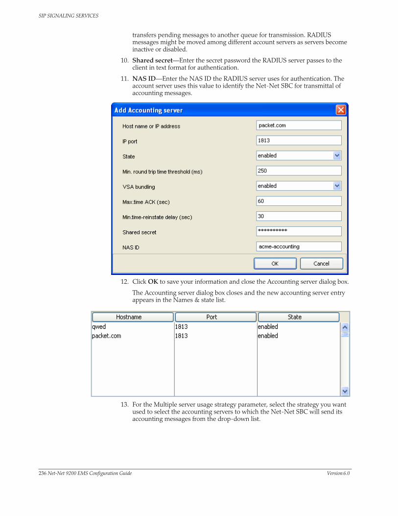
SIP SIGNALING SERVICES
transfers pending messages to another queue for transmission. RADIUS messages might be moved among different account servers as servers become inactive or disabled.
10. Shared secret—Enter the secret password the RADIUS server passes to the client in text format for authentication.
11. NAS ID—Enter the NAS ID the RADIUS server uses for authentication. The account server uses this value to identify the Net-Net SBC for transmittal of accounting messages.
12. Click OK to save your information and close the Accounting server dialog box.
The Accounting server dialog box closes and the new accounting server entry appears in the Names & state list.
13. For the Multiple server usage strategy parameter, select the strategy you want used to select the accounting servers to which the Net-Net SBC will send its accounting messages from the drop-down list.
236 Net-Net 9200 EMS Configuration Guide Version 6.0
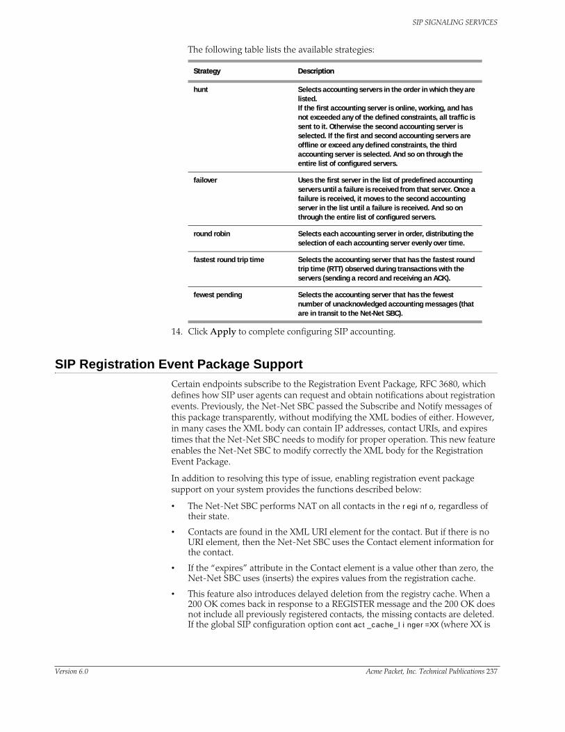
SIP SIGNALING SERVICES
The following table lists the available strategies:
14. Click Apply to complete configuring SIP accounting.
SIP Registration Event Package SupportCertain endpoints subscribe to the Registration Event Package, RFC 3680, which defines how SIP user agents can request and obtain notifications about registration events. Previously, the Net-Net SBC passed the Subscribe and Notify messages of this package transparently, without modifying the XML bodies of either. However, in many cases the XML body can contain IP addresses, contact URIs, and expires times that the Net-Net SBC needs to modify for proper operation. This new feature enables the Net-Net SBC to modify correctly the XML body for the Registration Event Package.
In addition to resolving this type of issue, enabling registration event package support on your system provides the functions described below:
• The Net-Net SBC performs NAT on all contacts in the reginfo, regardless of their state.
• Contacts are found in the XML URI element for the contact. But if there is no URI element, then the Net-Net SBC uses the Contact element information for the contact.
• If the “expires” attribute in the Contact element is a value other than zero, the Net-Net SBC uses (inserts) the expires values from the registration cache.
• This feature also introduces delayed deletion from the registry cache. When a 200 OK comes back in response to a REGISTER message and the 200 OK does not include all previously registered contacts, the missing contacts are deleted. If the global SIP configuration option contact_cache_linger=XX (where XX is
Strategy Description
hunt Selects accounting servers in the order in which they are listed.If the first accounting server is online, working, and has not exceeded any of the defined constraints, all traffic is sent to it. Otherwise the second accounting server is selected. If the first and second accounting servers are offline or exceed any defined constraints, the third accounting server is selected. And so on through the entire list of configured servers.
failover Uses the first server in the list of predefined accounting servers until a failure is received from that server. Once a failure is received, it moves to the second accounting server in the list until a failure is received. And so on through the entire list of configured servers.
round robin Selects each accounting server in order, distributing the selection of each accounting server evenly over time.
fastest round trip time Selects the accounting server that has the fastest round trip time (RTT) observed during transactions with the servers (sending a record and receiving an ACK).
fewest pending Selects the accounting server that has the fewest number of unacknowledged accounting messages (that are in transit to the Net-Net SBC).
Version 6.0 Acme Packet, Inc. Technical Publications 237

SIP SIGNALING SERVICES
the number of seconds to wait before deleting), then the contacts to be deleted remain for the specified number of seconds before they in fact are deleted.
Enabling Registration Event Package Support
You can enable this feature as part of the global SIP configuration, using the configuration’s Options parameter.
To enable SIP Registration overload protection on your Net-Net SBC using the Net-Net EMS:
1. Click the Net-Net SBC you are configuring in the Net-Net EMS navigation tree.
The SBC System window appears in the Net-Net EMS display pane.
2. Click the SIP tab and then the Options and tags subtab.
3. Click Options in the Option section of the screen.
The Options window appears.
4. Click the nat_reginfo option from the Available options window.
238 Net-Net 9200 EMS Configuration Guide Version 6.0

SIP SIGNALING SERVICES
5. Click to move the option to the Selected options list. The option name appears along with a description in the lower part of the window.
6. Click OK.
Version 6.0 Acme Packet, Inc. Technical Publications 239

SIP SIGNALING SERVICES
Configurable Timers and Counters for SIPIn prior releases of the Net-Net OS, SIP timers and counters are only configurable globally. This new release gives you the ability to configure timers for each SIP interface for greater flexibility. You can set the expiration times for SIP messages, and you can set a counter that restricts the number of contacts that the Net-Net SBC tries when it receives a REDIRECT.
Net-Net EMS Instructions and Examples
To set timers and counters for SIP interfaces:
1. Click Realms in the Net-Net EMS navigation tree.
The Realm table appears in the display pane.
2. Click the realm to which you want to configure in the table and click Edit. The Edit Realm window appears.
3. Click the Service/Protocols tab. The Realm Services table appears.
4. Click the SIP service you want to configure in the table and click Edit. The Edit SIP service window appears.
5. Click the SIP interface tab.
6. Scroll to the Configurable timers and counters section.
7. Transaction expire/timer F (secs)—Enter the TTL in seconds for SIP transactions. This timer controls the following timers specified in RFC 3261:
• Timer B—SIP INVITE transaction timeout
• Timer F—non-INVITE transaction timeout
• Timer H—Wait time for ACK receipt
• Timer TEE—Used to transmit final responses before receiving an ACK
You can leave this parameter set to the default value of 0 or enter a value up to 999999999. If you set this parameter to 0, the Net-Net SBC uses the timer value from the global SIP configuration.
8. INVITE expire/timer B (secs)—Enter the TTL in seconds for a SIP client/server transaction after receiving a provisional response.
You set this timer for the client and the sever by configuring it on the SIP interface corresponding to the core or access side.
240 Net-Net 9200 EMS Configuration Guide Version 6.0

SIP SIGNALING SERVICES
You can leave this parameter set to the default value of 0 or enter a value up to 999999999. If you set this parameter to 0, then the Net-Net SBC uses the timer value from the global SIP configuration.
9. Max REDIRECT contacts—Enter the maximum number of contacts or routes for the Net-Net SBC to attempt when it receives a SIP Redirect (3xx Response). If you leave this parameter set to the default value of 0, the Net-Net SBC will not exercise restrictions on the number of contacts or routes. The value range for this parameter is 0 to 10.
10. Click Apply.
Version 6.0 Acme Packet, Inc. Technical Publications 241

SIP SIGNALING SERVICES
SIP Session Agent Status Based on SIP ResponseYou can configure SIP response codes to take session agents out of service or put them in service. You can set the SIP response message that either takes a session agent out of service or allows it to remain in service when it responds to the Net-Net SBC’s ping request.
In prior releases, the Net-Net SBC determined session agents’ health by sending them ping messages using a SIP method that you configure.d Commonly, the method is an OPTIONS request. If it receives any response from the session agent, then the Net-Net SBC deems that session agent available for use.
However, issues can arise when session agents are administratively out of service, but able to respond to OPTIONs requests. A session agent like this might only respond with a 200 OK when in service, and send a 4xx or 5xx message otherwise.
Details of this feature are as follows:
• The Net-Net SBC only considers a session agent in service when it responds to a request method you set with the final response code that you also set. If a final response code is set, then provisional responses are not used for determining whether or not to take a session agent out of service. If the Net-Net SBC receives a final response code that does not match the session agent configuration, it treats the session agent as though it had not responded.
• The Net-Net SBC takes a session agent out of service when it receives an error response for dialog creating request with a response code listed in the Response codes that put SA out of service parameter.
• In the case where a the session agent’s response has a Retry-After header, the Net-Net SBC tries to bring the session agent back into service after the period of time specified in the header. To do so, it sends another ping request.
How It Works There are two lists you can configure in the session agent configuration to determine status:
• In-service list—Defines the response codes that keep a session agent in service when they appear in its response to the Net-Net SBC’s ping request. Furthermore, the Net-Net SBC takes the session agent out of service should a response code be used that does not appear on this list.
• Out-of-service list—Defines the response codes that take a session agent out of service when they appear in its response to the Net-Net SBC’s ping request.
When the Net-Net SBC receives a session agent’s response to its ping request, it first checks to see if there is an in-service list of responses configured for that session agent. If the list is configured and the Net-Net SBC determines that there is a match, the session agent is deemed in service. Otherwise it takes the session agent out of service. In this way, the in-service list takes precedence over the out-of-service list. If you configure the in-service list, then the Net-Net SBC ignores the out-of-service list.
If there is no list of in-service responses for the session agent, then the Net-Net SBC checks the out of service list. If it is configured and the Net-Net SBC determines that there is a match, the Net-Net SBC removes that session agent from service. If there is no match, then the session agent is deemed in service.
242 Net-Net 9200 EMS Configuration Guide Version 6.0

SIP SIGNALING SERVICES
Net-Net EMS Instructions and Examples
The Net-Net SBC first checks for the presence of the in-service list. If it finds one, it ignores the out-of-service list. If you want to use the out-of-service list, do not configure the in-service list. The value range is 2xx to 6xx as a comma-separated list of response codes or response code ranges. For example, 401, 404, 484-486.
In-Service Response Codes
To configure SIP response code(s):
1. Click Session agents in the Net-Net EMS navigation tree.
The Session agent table appears in the display pane.
2. Click a SIP session agent in the table to select it.
3. Click Edit. The Edit Session agent window appears in the display pane.
4. Click the SIP session agent constraints tab.
5. Response codes that put SA in service—Click Add. The Add Inservice response code dialog box appears.
6. SIP response code—Enter the SIP response code, or range of codes, that keep a session agent in service when they appear in its response to the Net-Net SBC’s ping request.
The Net-Net SBC takes the session agent out of service should a response code be used that does not appear on this list.
7. Click OK. The response code appears in the Response codes that put SA in service list.
8. Repeat steps 5 to 7 to enter all response codes you want to use.
9. If you do not plan to create a list of out-of-service response codes, click Apply.
Version 6.0 Acme Packet, Inc. Technical Publications 243

SIP SIGNALING SERVICES
Out-Of-Service Response Codes
1. Response codes that put SA out-of-service—Click Add. The Outservice response code dialog box appears.
2. SIP response code—Enter the SIP response code, or range of codes, that keep a session agent out-of- service when they appear in its response to the Net-Net SBC’s ping request.
3. Click OK. The response code appears in the Response codes that put SA out-of-service list.
4. Repeat steps 1 to 3 to enter all response codes you want to use.
5. Click Apply.
SIP Session Agent Group RecursionYou can configure a SIP session agent group (SAG) to try all of its session agents rather than to the next-best local policy match if the first session agent in the SAG fails. When you enable SIP SAG recursion, the Net-Net SBC will try the additional session agents in the selected SAG if the previous session agent fails. You can also set specific response codes in the SAG configuration that terminate the recursion. This method of terminating recursion is similar to the Net-Net SBC’s ability to stop recursion for SIP interfaces and session agents.
In prior releases, the Net-Net SBC performs routing by using local policies, trunk group URIs, cached services routes, and local route tables. Local policies and trunk group URIs can use SAGs to find the most appropriate next-hop session agent based on the load balancing scheme you choose for that SAG: round robin, hunt, proportional distribution, least busy, and lowest sustained rate.
When it locates a SAG and selects a specific session agent, the Net-Net SBC tries only that single session agent. Instead of trying other members of the SAG, the Net-Net SBC recurses to the local policy that is the next best match. This happens because the Net-Net SBC typically chooses a SAG based on the fact that it has not breached its constraints, but the Net-Net SBC only detects failed call attempts (due to unreachable next hops, unresolved ENUM queries, or SIP 4xx/5xx/6xx failure responses) after it has checked constraints. So the Net-Net only re-routes if there are additional matching local policies.
244 Net-Net 9200 EMS Configuration Guide Version 6.0

SIP SIGNALING SERVICES
How It Works Session agents are selected according to the strategy you set for the SAG, and these affect the way that the Net-Net SBC selects session agents when this feature enabled:
• Round robin and hunt—The Net-Net SBC selects the first session agent according to the strategy, and it selects subsequent session agents based on the order they are entered into the configuration.
• Proportional distribution, least busy, and lowest sustained rate—The Net-Net SBC selects session agents based on the list of session agents sorted by the criteria specified.
You can terminate recursion based on SIP response codes that you enter into the SAG configuration. You can configure a SAG with any SIP response code in the 3xx, 4xx, and 5xx groups. Since you can also set such a list in the session agent configuration, this list is additive to that one so that you can define additional codes for a session agent group with out having to repeat the ones set for a session agent.
Configuring SIP Session Agent Recursion
To enable SIP SAG recursion and set response code to terminate recursion:
1. Click Session agent groups in the Net-Net EMS navigation tree.
The Session agent group table appears in the display pane.
2. Select a SIP session agent group in the table and click Edit. The Edit Session agent group window appears.
3. SAG recursion—Click the checkbox to enable SAG recursion.
4. For the Response codes that stop recursion parameter, click Add. The SIP response codes dialog box appears.
5. SIP response code—Enter a SIP response code, or range of codes, that terminate recursion within the SAG. On encountering the specified response code(s), the Net-Net SBC returns a final response to the UAC.
Version 6.0 Acme Packet, Inc. Technical Publications 245

SIP SIGNALING SERVICES
6. Click OK. The response code appears in the Response codes that stop recursion list.
7. Click Apply.
246 Net-Net 9200 EMS Configuration Guide Version 6.0

SIP SIGNALING SERVICES
Restricted Media LatchingThis section explains how to configure restricted media latching, which lets the Net-Net SBC latch only to media from a known source IP address, in order to learn and latch the dynamic UDP port number. The restricting IP address’s origin can be either the SDP information or the SIP message’s Layer 3 (L3) IP address, depending on the configuration.
About Latching Latching is when the Net-Net SBC listens for the first RTP packet from any source address/port for the destination address/port of the Net-Net SBC. The destination address/port is allocated dynamically and sent in the SDP. After it receives a RTP packet for that allocated destination address/port, the Net-Net SBC only allows subsequent RTP packets from that same source address/port for that particular Net-Net SBC destination address/port. Latching does not imply that the latched source address/port is used for the destination of the reverse direction RTP packet flow (it does not imply the Net-Net SBC will perform symmetric RTP).
Restricted Latching The Net-Net SBC restricts latching of RTP/RTCP media for all calls within a realm. It latches to media based on one of the following:
• SDP: the IP address and address range based on the received SDP c= connect address line in the offer and answer.
• Layer 3: the IP address and address range based on the received L3 IP address of the offer or answer. This option is for access registered HNT endpoints. If the L3 IP address is locally known and cached by the Net-Net SBC as the public SIP contact address, that information could be used instead of waiting for a response. The Net-Net SBC might use the L3 IP address restriction method for all calls regardless of whether the endpoint is behind a NAT or not, for the same realms.
Symmetric Latching A mode where a device’s source address/ports for the RTP/RTCP it sends to the Net-Net SBC that are latched, are then used for the destination of RTP/RTCP sent to the device.
How it Works After allocating the media session in SIP, the Net-Net SBC sets the restriction mode and the restriction mask for the calling side as well as for the called side. It sets the source address and address prefix bits in the flow. It also parses and loads the source flow address into the MIBOCO messages. After receiving the calling SDP, the Net-Net SBC sets the source address (address and address prefix) in the appropriate flow (the flow going from calling side to the called side). After receiving the SDP from the called side, the Net-Net SBC sets the source address in the flow going from the called side to the calling side.
The Net-Net SBC uses either the address provided in the SDP or the layer 3 signaling address for latching. You also configure the Net-Net SBC to enable latching so that when it receives the source flow address, it sets the address and prefix in the NAT flow. When the NAT entry is installed, all the values are set correctly. In addition, sipd sends the information for both the incoming and outgoing flows. After receiving SDP from the called side sipd, the Net-Net SBC sends information for both flows to the MBCD so that the correct NAT entries are installed.
Version 6.0 Acme Packet, Inc. Technical Publications 247

SIP SIGNALING SERVICES
Enabling restricted latching may make the Net-Net SBC wait for a SIP/SDP response before latching, if the answerer is in a restricted latching realm. This is necessary because the Net-Net SBC does not usually know what to restrict latching to until the media endpoint is reached. The only exception could be when the endpoint’s contact/IP is cached.
Relationship to Symmetric Latching
The current forced HNT symmetric latching feature lets the Net-Net SBC assume devices are behind NATs, regardless of their signaled IP/SIP/SDP layer addresses. The Net-Net SBC latches on any received RTP destined for the specific IP address/port of the Net-Net SBC for the call, and uses the latched source address/port for the reverse flow destination information.
If both restricted latching and symmetric latching are enabled, the Net-Net SBC only latches if the source matches the restriction, and the reverse flow will only go to the address/port latched to, and thus the reverse flow will only go to an address of the same restriction.
• Symmetric latching is enabled.
If symmetric latching is enabled, the Net-Net SBC sends the media in the opposite direction to the same IP and port, after it latches to the source address of the media packet.
• Symmetric latching is disabled.
If symmetric latching is disabled, the Net-Net SBC only latches the incoming source. The destination of the media in the reverse direction is controlled by the SDP address.
Example 1 A typical example is when the Net-Net SBC performs HNT and non-HNT registration access for endpoints. Possibly the SDP might not be correct, specifically if the device is behind a NAT. Therefore the Net-Net SBC needs to learn the address for which to restrict the media latching, based on the L3 IP address. If the endpoint is not behind a NAT, then the SDP could be used instead if preferred. However, one can make some assumptions that access-type cases will require registration caching, and the cached fixed contact (the public FW address) could be used instead of waiting for any SDP response.
Example 2 Another example is when a VoIP service is provided using symmetric-latching. A B2BUA/proxy sits between HNT endpoints and the Net-Net SBC, and calls do not appear to be behind NATs from the Net-Net SBC’s perspective. The Net-Net SBC’s primary role, other than securing softswitches and media gateways, is to provide symmetric latching so that HNT media will work from the endpoints.
To ensure the Net-Net SBC’s latching mechanism is restricted to the media from the endpoints when the SIP Via and Contact headers are the B2BUA/proxy addresses and not the endpoints’, the endpoint’s real (public) IP address in the SDP of the offer/answer is used. The B2BUA/proxy corrects the c= line of SDP to that of the endpoints’ public FW address.
The Net-Net SBC would then restrict the latching to the address in the SDP of the offer from the access realm (for inbound calls) or the SDP answer (for outbound calls).
248 Net-Net 9200 EMS Configuration Guide Version 6.0

SIP SIGNALING SERVICES
Configuring Restricted Latching
To configure restricted latching:
1. Click Realms in the Net-Net EMS navigation tree. The Realm table appears in the display pane.
2. Click the realm to which you want to configure in the table and click Edit. The Edit Realm window appears.
3. Scroll to the Restricted latching section.
4. Restricted latching mode—Select the restricted latching mode:
• none: no latching used
• sdp: use the address provided in the SDP for latching
• peer-ip: use the layer 3 signaling address for latching
5. Prefix for the source latched address—Enter the number of address bits you want used for the source latched address. If set to 32, the complete IP address is matched. This field will be used only if restricted latching is used.
6. Click Apply.
Version 6.0 Acme Packet, Inc. Technical Publications 249

SIP SIGNALING SERVICES
SIP Enforcement Profile and Allowed MethodsEnforcement profile lets you configure sets of SIP methods that you want applied to: the global SIP configuration, a SIP interface, a realm, or a SIP session agent. The enforcement profile is a named list of allowed methods that you configure and then reference from the configuration where you want those methods applied.
Configuring Enforcement Profiles and Allowed Methods
You need to configure an enforcement profile with a name and the list of SIP methods you want to designate as allowed. Then you need configure the global SIP configuration, a SIP interface, a realm, or SIP session agent to use the set.
Creating an Enforcement Profile
To create an enforcement profile:
1. Click Profiles in the Net-Net EMS navigation tree. The Profiles window appears in the display pane.
2. Click the SIP Enforcement tab. The SIP enforcement profile table appears.
3. Click Add. The Add Enforcement Profile dialog box appears.
4. Name—Enter the name for the enforcement profile. You can apply this set of allowed SIP headers in: the global SIP configuration, a SIP interface, a realm, or SIP session agent.
5. Allowed methods—Click Add. The Allowed methods dialog box appears.
6. Allowed methods—Choose a SIP method that you want to allow for this profile from the drop-down list.
7. Click OK to close the dialog box. The method appears in the Allowed methods list.
250 Net-Net 9200 EMS Configuration Guide Version 6.0

SIP SIGNALING SERVICES
8. Repeat steps 5 through 7 to add methods to the list.
9. Click Apply.
Applying SIP Enforcement Profiles
You can apply an enforcement profile to: the global SIP configuration, a SIP interface, a realm, or SIP session agent. This section shows you how to do all four. Remember that if you are adding this functionality to a pre-existing configuration, you need to select the configuration you want to edit.
Applying to Global Configuration
To apply an enforcement profile to the global SIP configuration:
1. Click the Net-Net SBC you are configuring in the Net-Net EMS navigation tree.
The SBC System window appears in the Net-Net EMS display pane.
2. Click the SIP tab.
3. Enforcement profile—Choose the name of the enforcement profile you want to apply to the global SIP configuration from the drop-down list.
4. Click Apply.
Applying to SIP Interface
To apply an enforcement profile to a SIP interface:
1. Click Realms in the Net-Net EMS navigation tree.
Version 6.0 Acme Packet, Inc. Technical Publications 251

SIP SIGNALING SERVICES
The Realm window appears in the display pane.
2. Click the realm you want to edit in the Realm table and click Edit. The Edit Realm window appears.
3. Click the Services/Protocols tab. The Realm Services table appears.
4. Click the service name in the Realm Services table and click Edit. The Edit SIP service window appears.
5. Click the SIP interface tab.
6. Enforcement profile—Choose the name of the enforcement profile you want to apply to the SIP interface from the drop-down list.
7. Click Apply.
Applying to SIP Session Agent
To apply an enforcement profile to a SIP session agent:
1. Click Session agents in the Net-Net EMS navigation tree.
The Session agent window appears in the display pane.
2. Click the SIP session agent you want to edit in the Session agent table and click Edit. The Edit Session agent window appears.
3. Enforcement profile—Choose the name of the enforcement profile you want to apply to the SIP session agent from the drop-down list.
4. Click Apply.
252 Net-Net 9200 EMS Configuration Guide Version 6.0

SIP SIGNALING SERVICES
Applying to a Realm To apply an enforcement profile to a realm:
1. Click Realms in the Net-Net EMS navigation tree.
The Realm window appears in the display pane.
2. Click a realm in the realm table to select it and click Edit. The Edit Realm window appears.
3. Click the Realm tab.
4. Enforcement profile—Choose the name of the enforcement profile you want to apply to the realm from the drop-down list.
5. Click Apply.
Ensuring Placement of RADIUS Attributes in CSV FileUsing the Net-Net SBC’s local CDR storage feature, you can enable the Net-Net SBC to write CDRs as comma-delimited ASCII records to files on the Net-Net SBC. The types of records are controlled by the same accounting configuration parameters used for RADIUS; the fields of the comma-delimited entries correspond to RADIUS Start, Interim, and Stop records. This feature is mainly used with the Net-Net SBC’s FTP push capability, so that the files stored locally are periodically sent to a an FTP server you designate.
By default, unpopulated or unused fields in the RADIUS CDR are omitted from the locally-stored CSV file; there is no fixed position for a RADIUS attribute across all CSV files. Instead, the missing values are skipped in the CSV file causing the order and appearance for attribute values to differ from record to record.
You can guarantee the placement of attributes in locally-stored CSV files by enabling the Include empty fields in each CDR generated parameter. With this parameter enabled, RADIUS records sent to a RADIUS client contain even empty attributes with an integer, date and time, or IP address format; the default value is zero. When there is no value to report:
• IP address attribute reports as 0.0.0.0
• Date and time attribute reports as 00:00:00.000 UTC JAN 01 1970
Version 6.0 Acme Packet, Inc. Technical Publications 253
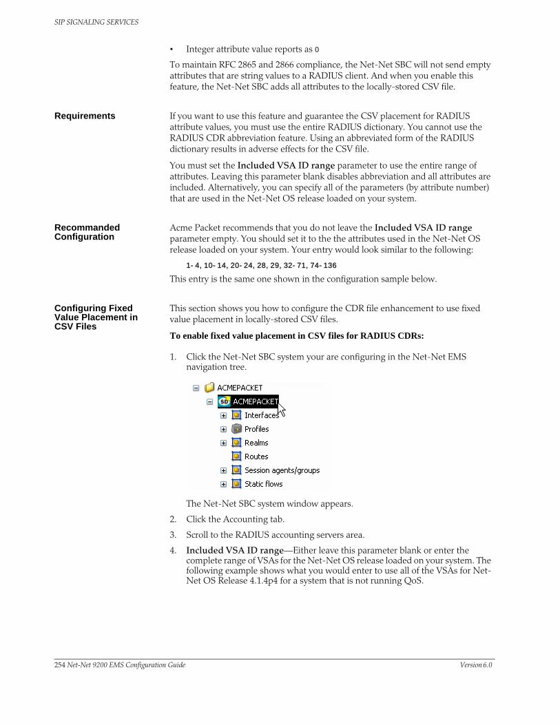
SIP SIGNALING SERVICES
• Integer attribute value reports as 0
To maintain RFC 2865 and 2866 compliance, the Net-Net SBC will not send empty attributes that are string values to a RADIUS client. And when you enable this feature, the Net-Net SBC adds all attributes to the locally-stored CSV file.
Requirements If you want to use this feature and guarantee the CSV placement for RADIUS attribute values, you must use the entire RADIUS dictionary. You cannot use the RADIUS CDR abbreviation feature. Using an abbreviated form of the RADIUS dictionary results in adverse effects for the CSV file.
You must set the Included VSA ID range parameter to use the entire range of attributes. Leaving this parameter blank disables abbreviation and all attributes are included. Alternatively, you can specify all of the parameters (by attribute number) that are used in the Net-Net OS release loaded on your system.
Recommanded Configuration
Acme Packet recommends that you do not leave the Included VSA ID range parameter empty. You should set it to the the attributes used in the Net-Net OS release loaded on your system. Your entry would look similar to the following:
1-4,10-14,20-24,28,29,32-71,74-136
This entry is the same one shown in the configuration sample below.
Configuring Fixed Value Placement in CSV Files
This section shows you how to configure the CDR file enhancement to use fixed value placement in locally-stored CSV files.
To enable fixed value placement in CSV files for RADIUS CDRs:
1. Click the Net-Net SBC system your are configuring in the Net-Net EMS navigation tree.
The Net-Net SBC system window appears.
2. Click the Accounting tab.
3. Scroll to the RADIUS accounting servers area.
4. Included VSA ID range—Either leave this parameter blank or enter the complete range of VSAs for the Net-Net OS release loaded on your system. The following example shows what you would enter to use all of the VSAs for Net-Net OS Release 4.1.4p4 for a system that is not running QoS.
254 Net-Net 9200 EMS Configuration Guide Version 6.0

SIP SIGNALING SERVICES
5. Include empty fields in each CDR generated—Click this checkbox if you want to enable the CDR file format feature.
6. Click Apply.
CSV File Placement for RADIUS Attribute Values
This section contains three tables that show where in a locally-generated CSV file specific attributes appear—one each for Start, Interim, and Stop records
Start Record CSV Placement
CSV Placement Attribute Name VSA ID Number
1 Acct-Status-Type
2 NAS-IP-Address
3 NAS-Port
4 Acct-Session-Id
5 Acme-Session-Ingress-CallId 3
6 Acme-Session--Egress-CallId 4
7 Acme-Session-Protocol-Type 43
8 Acme-Session--Generic-Id 40
9 Calling-Station-Id
10 Called-Station-Id
11 h323-setup-time
12 h323-connect-time
13 Acme-Session-Egress-Realm 42
14 Acme-Session-Ingress-Realm 41
15 Acme-FlowId_FS1_F 1
16 Acme-FlowType_FS1_F 2
17 Acme-Flow-In-Realm_FS1_F 10
18 Acme-Flow-In-Src-Addr_FS1_F 11
19 Acme-Flow-In-Src-Port_FS1_F 12
20 Acme-Flow-In-Dst-Addr_FS1_F 13
21 Acme-Flow-In-Dst-Port_FS1_F 14
22 Acme-Flow-Out-Realm_FS1_F 20
23 Acme-Flow-Out-Src-Addr_FS1_F 21
24 Acme-Flow-Out-Src-Port_FS1_F 22
Version 6.0 Acme Packet, Inc. Technical Publications 255

SIP SIGNALING SERVICES
25 Acme-Flow-Out-Dst-Addr_FS1_F 23
26 Acme-Flow-Out-Dst-Port_FS1_F 24
27 Acme-FlowID_FS1_R 78
28 Acme-FlowType_FS1_R 79
29 Acme-Flow-In-Realm_FS1_R 80
30 Acme-Flow-In-Src-Addr_FS1_R 81
31 Acme-Flow-In-Src-Port_FS1_R 82
32 Acme-Flow-In-Dst-Addr_FS1_R 83
33 Acme-Flow-In-Dst-Port_FS1_R 84
34 Acme-Flow-Out-Realm_FS1_R 85
35 Acme-Flow-Out-Src-Addr_FS1_R 86
36 Acme-Flow-Out-Src-Port_FS1_R 87
37 Acme-Flow-Out-Dst-Addr_FS1_R 88
38 Acme-Flow-Out-Dst-Port_FS1_R 89
39 Acme-FlowID_FS2_F 90
40 Acme-FlowType_FS2_F 91
41 Acme-Flow-In-Realm_FS2_F 92
42 Acme-Flow-In-Src-Addr_FS2_F 93
43 Acme-Flow-In-Src-Port_FS2_F 94
44 Acme-Flow-In-Dst-Addr_FS2_F 95
45 Acme-Flow-In-Dst-Port_FS2_F 96
46 Acme-Flow-Out-Realm_FS2_F 97
47 Acme-Flow-Out-Src-Addr_FS2_F 98
48 Acme-Flow-Out-Src-Port_FS2_F 99
49 Acme-Flow-Out-Dst-Addr_FS2_F 100
50 Acme-Flow-Out-Dst-Port_FS2_F 101
51 Acme-FlowID_FS2_R 112
52 Acme-FlowType_FS2_R 113
53 Acme-Flow-In-Realm_FS2_R 114
54 Acme-Flow-In-Src-Addr_FS2_R 115
55 Acme-Flow-In-Src-Port_FS2_R 116
56 Acme-Flow-In-Dst-Addr_FS2_R 117
57 Acme-Flow-In-Dst-Port_FS2_R 118
CSV Placement Attribute Name VSA ID Number
256 Net-Net 9200 EMS Configuration Guide Version 6.0

SIP SIGNALING SERVICES
Interim Record CSV Placement
58 Acme-Flow-Out-Realm_FS2_R 119
59 Acme-Flow-Out-Src-Addr_FS2_R 120
60 Acme-Flow-Out-Src-Port_FS2_R 121
61 Acme-Flow-Out-Dst-Addr_FS2_R 122
62 Acme-Flow-Out-Dst-Port_FS2_R 123
63 Acme-Session-Charging-Vector 54
64 Acme-Session-Charging-Function_Address 55
65 Acme-Firmware-Version 56
66 Acme-Local-Time-Zone 57
67 Acme-Post-Dial-Delay 58
68 Acme-Primary-Routing-Number 64
69 Acme-Originating-Trunk-Group 65
70 Acme-Terminating-Trunk-Group 66
71 Acme-Originating-Trunk-Context 67
72 Acme-Terminating-Trunk-Context 68
73 Acme-P-Asserted-ID 69
74 Acme-Ingress-Local-Addr 74
75 Acme-Ingress-Remote-Addr 75
76 Acme-Egress-Local-Addr 76
77 Acme-Egress-Remote-Addr 77
78 Acme-SIP-Diversion 70
79 Acme-Egress-Final-Routing-Number 134
80 Acme-Session-Ingress-RPH 135
81 Acme-Session-Egress-RPH 136
CSV Placement Attribute Name VSA ID Number
CSV Placement Attribute Name VSA ID Number
1 Acct-Status-Type
2 NAS-IP-Address
3 NAS-Port
4 Acct-Session-Id
5 Acme-Session-Ingress-CallId 3
Version 6.0 Acme Packet, Inc. Technical Publications 257

SIP SIGNALING SERVICES
6 Acme-Session--Egress-CallId 4
7 Acme-Session-Protocol-Type 43
8 Acme-Session--Generic-Id 40
9 Calling-Station-Id
10 Called-Station-Id
11 h323-setup-time
12 h323-connect-time
13 Acme-Session-Egress-Realm 42
14 Acme-Session-Ingress-Realm 41
15 Acme-FlowId_FS1_F 1
16 Acme-FlowType_FS1_F 2
17 Acme-Flow-In-Realm_FS1_F 10
18 Acme-Flow-In-Src-Addr_FS1_F 11
19 Acme-Flow-In-Src-Port_FS1_F 12
20 Acme-Flow-In-Dst-Addr_FS1_F 13
21 Acme-Flow-In-Dst-Port_FS1_F 14
22 Acme-Flow-Out-Realm_FS1_F 20
23 Acme-Flow-Out-Src-Addr_FS1_F 21
24 Acme-Flow-Out-Src-Port_FS1_F 22
25 Acme-Flow-Out-Dst-Addr_FS1_F 23
26 Acme-Flow-Out-Dst-Port_FS1_F 24
27 Acme-Calling-RTCP-Packets-Lost_FS1 32
28 Acme-Calling-RTCP-Avg-Jitter_FS1 33
29 Acme-Calling-RTCP-Avg-Latency_FS1 34
30 Acme-Calling-RTCP-MaxJitter_FS1 35
31 Acme-Calling-RTCP-MaxLatency_FS1 36
32 Acme-Calling-RTP-Packets-Lost_FS1 37
33 Acme-Calling-RTP-Avg-Jitter_FS1 38
34 Acme-Calling-RTP-MaxJitter_FS1 39
35 Acme-Calling-Octets_FS1 28
36 Acme-Calling-Packets_FS1 29
37 Acme-FlowID_FS1_R 78
38 Acme-FlowType_FS1_R 79
CSV Placement Attribute Name VSA ID Number
258 Net-Net 9200 EMS Configuration Guide Version 6.0

SIP SIGNALING SERVICES
39 Acme-Flow-In-Realm_FS1_R 80
40 Acme-Flow-In-Src-Addr_FS1_R 81
41 Acme-Flow-In-Src-Port_FS1_R 82
42 Acme-Flow-In-Dst-Addr_FS1_R 83
43 Acme-Flow-In-Dst-Port_FS1_R 84
44 Acme-Flow-Out-Realm_FS1_R 85
45 Acme-Flow-Out-Src-Addr_FS1_R 86
46 Acme-Flow-Out-Src-Port_FS1_R 87
47 Acme-Flow-Out-Dst-Addr_FS1_R 88
48 Acme-Flow-Out-Dst-Port_FS1_R 89
49 Acme-Called-RTCP-Packets-Lost_FS1 46
50 Acme-Called-RTCP-Avg-Jitter_FS1 47
51 Acme-Called-RTCP-Avg-Latency_FS1 48
52 Acme-Called-RTCP-MaxJitter_FS1 49
53 Acme-Called-RTCP-MaxLatency_FS1 50
54 Acme-Called-RTP-Packets-Lost_FS1 51
55 Acme-Called-RTP-Avg-Jitter_FS1 52
56 Acme-Called-RTP-MaxJitter_FS1 53
57 Acme-Called-Octets_FS1 44
58 Acme-Called-Packets_FS1 45
59 Acme-FlowID_FS2_F 90
60 Acme-FlowType_FS2_F 91
61 Acme-Flow-In-Realm_FS2_F 92
62 Acme-Flow-In-Src-Addr_FS2_F 93
63 Acme-Flow-In-Src-Port_FS2_F 94
64 Acme-Flow-In-Dst-Addr_FS2_F 95
65 Acme-Flow-In-Dst-Port_FS2_F 96
66 Acme-Flow-Out-Realm_FS2_F 97
67 Acme-Flow-Out-Src-Addr_FS2_F 98
68 Acme-Flow-Out-Src-Port_FS2_F 99
69 Acme-Flow-Out-Dst-Addr_FS2_F 100
70 Acme-Flow-Out-Dst-Port_FS2_F 101
71 Acme-Calling-RTCP-Packets-Lost_FS2 104
CSV Placement Attribute Name VSA ID Number
Version 6.0 Acme Packet, Inc. Technical Publications 259

SIP SIGNALING SERVICES
72 Acme-Calling-RTCP-Avg-Jitter_FS2 105
73 Acme-Calling-RTCP-Avg-Latency_FS2 106
74 Acme-Calling-RTCP-MaxJitter_FS2 107
75 Acme-Calling-RTCP-MaxLatency_FS2 108
76 Acme-Calling-RTP-Packets-Lost_FS2 109
77 Acme-Calling-RTP-Avg-Jitter_FS2 110
78 Acme-Calling-RTP-MaxJitter_FS2 111
79 Acme-Calling-Octets_FS2 102
80 Acme-Calling-Packets_FS2 103
81 Acme-FlowID_FS2_R 112
82 Acme-FlowType_FS2_R 113
83 Acme-Flow-In-Realm_FS2_R 114
84 Acme-Flow-In-Src-Addr_FS2_R 115
85 Acme-Flow-In-Src-Port_FS2_R 116
86 Acme-Flow-In-Dst-Addr_FS2_R 117
87 Acme-Flow-In-Dst-Port_FS2_R 118
88 Acme-Flow-Out-Realm_FS2_R 119
89 Acme-Flow-Out-Src-Addr_FS2_R 120
90 Acme-Flow-Out-Src-Port_FS2_R 121
91 Acme-Flow-Out-Dst-Addr_FS2_R 122
92 Acme-Flow-Out-Dst-Port_FS2_R 123
93 Acme-Called-RTCP-Packets-Lost_FS2 126
94 Acme-Called--RTCP-Avg-Jitter_FS2 127
95 Acme-Called--RTCP-Avg-Latency_FS2 128
96 Acme-Called--RTCP-MaxJitter_FS2 129
97 Acme-Called-RTCP-MaxLatency_FS2 130
98 Acme-Called-RTP-Packets-Lost_FS2 131
99 Acme-Called-RTP-Avg-Jitter_FS2 132
100 Acme-Called-RTP-MaxJitter_FS2 133
101 Acme-Called-Octets_FS2 124
102 Acme-Called-Packets_FS2 125
103 Acme-Session-Charging-Vector 54
104 Acme-Session-Charging-Function_Address 55
CSV Placement Attribute Name VSA ID Number
260 Net-Net 9200 EMS Configuration Guide Version 6.0

SIP SIGNALING SERVICES
Stop Record CSV Placement
105 Acme-Firmware-Version 56
106 Acme-Local-Time-Zone 57
107 Acme-Post-Dial-Delay 58
108 Acme-Primary-Routing-Number 64
109 Acme-Originating-Trunk-Group 65
110 Acme-Terminating-Trunk-Group 66
111 Acme-Originating-Trunk-Context 67
112 Acme-Terminating-Trunk-Context 68
113 Acme-P-Asserted-ID 69
114 Acme-Ingress-Local-Addr 74
115 Acme-Ingress-Remote-Addr 75
116 Acme-Egress-Local-Addr 76
117 Acme-Egress-Remote-Addr 77
118 Acme-SIP-Diversion 70
119 Acme-Intermediate_Time 63
120 Acme-Egress-Final-Routing-Number 134
121 Acme-Session-Ingress-RPH 135
122 Acme-Session-Egress-RPH 136
CSV Placement Attribute Name VSA ID Number
CSV Placement Attribute Name VSA ID Number
1 Acct-Status-Type
2 NAS-IP-Address
3 NAS-Port
4 Acct-Session-Id
5 Acme-Session-Ingress-CallId 3
6 Acme-Session--Egress-CallId 4
7 Acme-Session-Protocol-Type 43
8 Acme-Session--Generic-Id 40
9 Calling-Station-Id
10 Called-Station-Id
11 Acct-Terminate-Cause
Version 6.0 Acme Packet, Inc. Technical Publications 261

SIP SIGNALING SERVICES
12 Acct-Session-Time
13 h323-setup-time
14 h323-connect-time
15 h323-disconnect-time
16 h323-disconnect-cause
17 Acme-Session-Egress-Realm 42
18 Acme-Session-Ingress-Realm 41
19 Acme-FlowId_FS1_F 1
20 Acme-FlowType_FS1_F 2
21 Acme-Flow-In-Realm_FS1_F 10
22 Acme-Flow-In-Src-Addr_FS1_F 11
23 Acme-Flow-In-Src-Port_FS1_F 12
24 Acme-Flow-In-Dst-Addr_FS1_F 13
25 Acme-Flow-In-Dst-Port_FS1_F 14
26 Acme-Flow-Out-Realm_FS1_F 20
27 Acme-Flow-Out-Src-Addr_FS1_F 21
28 Acme-Flow-Out-Src-Port_FS1_F 22
29 Acme-Flow-Out-Dst-Addr_FS1_F 23
30 Acme-Flow-Out-Dst-Port_FS1_F 24
31 Acme-Calling-RTCP-Packets-Lost_FS1 32
32 Acme-Calling-RTCP-Avg-Jitter_FS1 33
33 Acme-Calling-RTCP-Avg-Latency_FS1 34
34 Acme-Calling-RTCP-MaxJitter_FS1 35
35 Acme-Calling-RTCP-MaxLatency_FS1 36
36 Acme-Calling-RTP-Packets-Lost_FS1 37
37 Acme-Calling-RTP-Avg-Jitter_FS1 38
38 Acme-Calling-RTP-MaxJitter_FS1 39
39 Acme-Calling-Octets_FS1 28
40 Acme-Calling-Packets_FS1 29
41 Acme-FlowID_FS1_R 78
42 Acme-FlowType_FS1_R 79
43 Acme-Flow-In-Realm_FS1_R 80
44 Acme-Flow-In-Src-Addr_FS1_R 81
CSV Placement Attribute Name VSA ID Number
262 Net-Net 9200 EMS Configuration Guide Version 6.0

SIP SIGNALING SERVICES
45 Acme-Flow-In-Src-Port_FS1_R 82
46 Acme-Flow-In-Dst-Addr_FS1_R 83
47 Acme-Flow-In-Dst-Port_FS1_R 84
48 Acme-Flow-Out-Realm_FS1_R 85
49 Acme-Flow-Out-Src-Addr_FS1_R 86
50 Acme-Flow-Out-Src-Port_FS1_R 87
51 Acme-Flow-Out-Dst-Addr_FS1_R 88
52 Acme-Flow-Out-Dst-Port_FS1_R 89
53 Acme-Called-RTCP-Packets-Lost_FS1 46
54 Acme-Called-RTCP-Avg-Jitter_FS1 47
55 Acme-Called-RTCP-Avg-Latency_FS1 48
56 Acme-Called-RTCP-MaxJitter_FS1 49
57 Acme-Called-RTCP-MaxLatency_FS1 50
58 Acme-Called-RTP-Packets-Lost_FS1 51
59 Acme-Called-RTP-Avg-Jitter_FS1 52
60 Acme-Called-RTP-MaxJitter_FS1 53
61 Acme-Called-Octets_FS1 44
62 Acme-Called-Packets_FS1 45
63 Acme-FlowID_FS2_F 90
64 Acme-FlowType_FS2_F 91
65 Acme-Flow-In-Realm_FS2_F 92
66 Acme-Flow-In-Src-Addr_FS2_F 93
67 Acme-Flow-In-Src-Port_FS2_F 94
68 Acme-Flow-In-Dst-Addr_FS2_F 95
69 Acme-Flow-In-Dst-Port_FS2_F 96
70 Acme-Flow-Out-Realm_FS2_F 97
71 Acme-Flow-Out-Src-Addr_FS2_F 98
72 Acme-Flow-Out-Src-Port_FS2_F 99
73 Acme-Flow-Out-Dst-Addr_FS2_F 100
74 Acme-Flow-Out-Dst-Port_FS2_F 101
75 Acme-Calling-RTCP-Packets-Lost_FS2 104
76 Acme-Calling-RTCP-Avg-Jitter_FS2 105
77 Acme-Calling-RTCP-Avg-Latency_FS2 106
CSV Placement Attribute Name VSA ID Number
Version 6.0 Acme Packet, Inc. Technical Publications 263

SIP SIGNALING SERVICES
78 Acme-Calling-RTCP-MaxJitter_FS2 107
79 Acme-Calling-RTCP-MaxLatency_FS2 108
80 Acme-Calling-RTP-Packets-Lost_FS2 109
81 Acme-Calling-RTP-Avg-Jitter_FS2 110
82 Acme-Calling-RTP-MaxJitter_FS2 111
83 Acme-Calling-Octets_FS2 102
84 Acme-Calling-Packets_FS2 103
85 Acme-FlowID_FS2_R 112
86 Acme-FlowType_FS2_R 113
87 Acme-Flow-In-Realm_FS2_R 114
88 Acme-Flow-In-Src-Addr_FS2_R 115
89 Acme-Flow-In-Src-Port_FS2_R 116
90 Acme-Flow-In-Dst-Addr_FS2_R 117
91 Acme-Flow-In-Dst-Port_FS2_R 118
92 Acme-Flow-Out-Realm_FS2_R 119
93 Acme-Flow-Out-Src-Addr_FS2_R 120
94 Acme-Flow-Out-Src-Port_FS2_R 121
95 Acme-Flow-Out-Dst-Addr_FS2_R 122
96 Acme-Flow-Out-Dst-Port_FS2_R 123
97 Acme-Called-RTCP-Packets-Lost_FS2 126
98 Acme-Called--RTCP-Avg-Jitter_FS2 127
99 Acme-Called--RTCP-Avg-Latency_FS2 128
100 Acme-Called--RTCP-MaxJitter_FS2 129
101 Acme-Called-RTCP-MaxLatency_FS2 130
102 Acme-Called-RTP-Packets-Lost_FS2 131
103 Acme-Called-RTP-Avg-Jitter_FS2 132
104 Acme-Called-RTP-MaxJitter_FS2 133
105 Acme-Called-Octets_FS2 124
106 Acme-Called-Packets_FS2 125
107 Acme-Session-Charging-Vector 54
108 Acme-Session-Charging-Function-Address 55
109 Acme-Firmware-Version 56
110 Acme-Local-Time-Zone 57
CSV Placement Attribute Name VSA ID Number
264 Net-Net 9200 EMS Configuration Guide Version 6.0
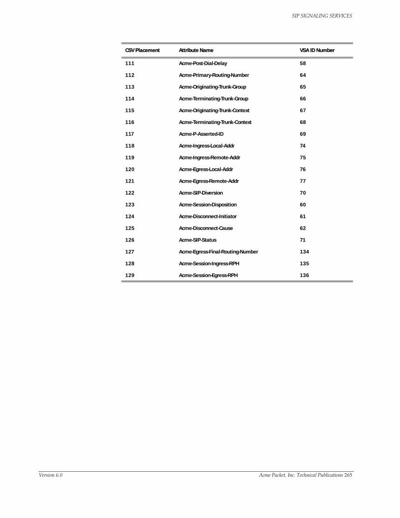
SIP SIGNALING SERVICES
111 Acme-Post-Dial-Delay 58
112 Acme-Primary-Routing-Number 64
113 Acme-Originating-Trunk-Group 65
114 Acme-Terminating-Trunk-Group 66
115 Acme-Originating-Trunk-Context 67
116 Acme-Terminating-Trunk-Context 68
117 Acme-P-Asserted-ID 69
118 Acme-Ingress-Local-Addr 74
119 Acme-Ingress-Remote-Addr 75
120 Acme-Egress-Local-Addr 76
121 Acme-Egress-Remote-Addr 77
122 Acme-SIP-Diversion 70
123 Acme-Session-Disposition 60
124 Acme-Disconnect-Initiator 61
125 Acme-Disconnect-Cause 62
126 Acme-SIP-Status 71
127 Acme-Egress-Final-Routing-Number 134
128 Acme-Session-Ingress-RPH 135
129 Acme-Session-Egress-RPH 136
CSV Placement Attribute Name VSA ID Number
Version 6.0 Acme Packet, Inc. Technical Publications 265
SIP SIGNALING SERVICES
HMR Performance EnhancementsThe Net-Net SBC’S SIP HMR feature is improved to provide better CPU utilization rates. Some of these improvements are internal to the Net-Net SBC architecture and do not affect how you use SIP HMR. You need to be aware of other changes that have an impact on how you configure HMR.
Configuration Order
The Net-Net SBC applies SIP header rules in the order you entered them. This guards against the Net-Net SBC’s removing data that might be used in the other header rules. In addition to providing this guard, the ordering provides you with ways to use manipulations strategically.
Besides taking note of the order in which header rules are configured, you must configure a given header rule prior to referencing it. For example, you must create Rule1 with the action store for the Contact header BEFORE you can create Rule2 which uses the stored value from the Contact header.
Expression Building Using Parentheses
You can use parantheses ( () )when you use HMR to support order of operations and to simplify header manipulation rules. This means that expressions such as “(sip + urp) - (u + rp)” can now be evaluated to sip. Previously, the same expression would have evaluated to sipurprp. In addition, you previously would have been required to create several different manipulation rules to perform the same expression.
Use of Escape Characters
When you configure HMR (using SIP manipulation rules, elements rules, etc.), you can now use escape characters in the match-value and new-value parameters to support escaping Boolean and string manipulation operators. .
You can also escape the escape character itself, so that it is used as a literal string. For example, the Net-Net SBC now treats the string \+1234 as +1234.
The following are escape characters: +, -, +^, -^, &, |, \, (, ), ., $, ^, and “.
New Comparison Types
The SIP header rules and the SIP element rules both contain a parameter called Comparison type, which is the way that you want SIP headers to be compared. Your new choices are:
• boolean—Used when you want to evaluate a referenced value by name to determine if its regular expression or Boolean expression matches TRUE or FALSE. You would choose the boolean setting when, for example, the match value is $Rule1 or ($Rule1 & ($Rule2@elem4|$Rule3.$elem1)).
You can also use the boolean setting on a specific stored match to determine whether or not that match has stored a value. This is useful when you use a regular expression that contains groupings. For example, the value $rule1.$elem1.$2 can be used as a match value, and then if the stored match $2 has any value, the resulting expression will be TRUE. But if the store match is empty, then the resulting expression will be FALSE.
Previously, the pattern-rule value included the behavior described here for boolean. Now, the pattern-rule value means only that the Net-Net SBC performs a regular expression comparison. If you are upgrading, this means that existing configurations where pattern-rule was set will be changed to boolean if the Net-Net SBC can parse the match value in the rule.
266 Net-Net 9200 EMS Configuration Guide Version 6.0

SIP SIGNALING SERVICES
• refer-case-sensitive—Used when you want to perform a case-sensitive comparison of the stored value (or pattern rule subgroup) against: a header parameter value, URI parameter value, or header value.
• refer-case-insensitive—Used when you want to perform a case-insensitive comparison of the stored value (or pattern rule subgroup) against: a header parameter value, URI parameter value, or header value.
Performing HMR on a Specific Header
HMR has been enhanced so that you can now operate on a specific instance of a given header. The syntax you use to accomplish this is similar to that you used to refer to a specific header rule stored value instance.
Using the header-name parameter, you can now add a trailing [<index>] value after the header name. This [<index>] is a numerical value representing the specific instance of the header on which to operate. However, the Net-Net SBC takes no action if the header does not exist. You can also use the caret (^) to reference the last header of that type (if there are multiple instances)
The count for referencing is zero-based, meaning that the first instance of the header counts as 0.
Note that the header instance functionality has no impact on HMR’s add action, and you cannot use this feature to insert headers into a specific location. Headers are added to the end of the list, except that Via headers are added to the top.
Version 6.0 Acme Packet, Inc. Technical Publications 267

SIP SIGNALING SERVICES
SIP Registration Burst Rate ControlThe Net-Net SBC lets you control SIP registration burst rates to smooth the registration rate. The Net-Net SBC’s can limit the number of:
• New register requests sent to a session agent
• Forwarded registrations from already-registered endpoints
While these methods successfully guard against the Net-Net SBC’s becoming overwhelmed with register requests, registration rates can still be too aggressive and a Registrar can be overwhelmed by an excessive amount of registrations.
SIP registration burst rate control lets you configure SIP session agents to control the registration burst rate to limit the number of new registration requests and to set the time window for that burst rate. When the registration rate exceeds the burst rate you set, the Net-Net SBC responds to new registration requests with 503 Service Unavailable messages.
Note: This constraint is not applied to re-registers resulting from a 401 Unauthorized challenge request.
Configuring SIP Registration Burst Rate Control
To configure SIP registration burst rate control:
1. Click Session agents in the Net-Net EMS navigation tree.
The Session agents window appears in the Net-Net EMS display pane.
2. Choose a SIP interface and click Edit.
3. Click the SIP session agent constraints tab.
4. Scroll to Maximum register burst rate (reg/sec) and Register burst window (sec).
5. Maximum register burst rate (reg/sec)—Enter the maximum number of new registrations you want this session agent to accept within the registration burst rate window. If this threshold is exceeded, the Net-Net SBC responds to new registration requests with 503 Service Unavailable messages. 0 is the minimum and default value for this parameter; the maximum value is 999999999.
6. Register burst window (sec)—Define the window size in seconds for the maximum number of allowable SIP registrations. 0 is the minimum and default value for this parameter; the maximum value is 999999999.
7. Click Apply.
268 Net-Net 9200 EMS Configuration Guide Version 6.0

SIP SIGNALING SERVICES
Version 6.0 Acme Packet, Inc. Technical Publications 269

SIP SIGNALING SERVICES
270 Net-Net 9200 EMS Configuration Guide Version 6.0

7 IMS Support
Net-Net SBC IMS SupportThe ETSI TISPAN NGN defines several subsystems that make up the NGN architecture. The model for the target NGN architecture is depicted below. Acme Packet's Net-Net Session Director is an integrated session control, policy enforcement and media management solution that incorporates functional components of the IP multimedia subsystem (IMS) the Resource and Admission Control Subsystem (RACS) and functions necessary for the interconnection with other IP networks/domains. The functions of the Net-Net SBC within the NGN architecture are divided into the interconnect border functions and the access border functions. The diagram below depicts the mapping of these functions across IMS architecture.
Net-Net SBC Access Border Functions
• Proxy CSCF (P-CSCF)
• Access/Core Border Gateway Function (A/C-BGF)
• RACF AF and SPDF functions
Version 6.0 Acme Packet, Inc. Technical Publications 233

IMS SUPPORT
Net-Net SBC Interconnect Border Functions
• Interconnect Border Control Function (I-BCF)
• Interworking Function (IWF)
• Interconnect Border Gateway Function (I-BGF)
IMS Access Border Functions The Net-Net SBC is deployed as the access point between the core IMS network and UEs to deliver the functions defined in the TISPAN architecture as the P-CSCF, and A-BGF. These two functions can not be separated.
P-CSCF Functions The Net-Net SBC performs the following functions in the role of P-CSCF:
• Forwards SIP REGISTER messages and maintains a cached mapping of the user info and the UE's Address of Record (AoR), including the far-end NAT address in the case of hosted NAT traversal (HNT).
• Forwards SIP messages to a S-CSCF based on service route discovery procedures.
• Performs local emergency session handling—Local routing policy is used by the Net-Net SBC to identify emergency sessions and provide unique routing (e.g. can route to a dedicated S-CSCF function for emergency session handling).
• Operates as a UA (B2BUA) for generating independent SIP transactions for security purposes and handling of abnormal conditions.
• Offers current session timers which are used to monitor for media faults and abandoned calls.
• Generation of CDRs—The Net-Net SBC generates real-time accounting records via RADIUS.
• Authorization of bearer resources and QoS management—With integrated BGF capabilities, the Net-Net SBC allocates bearer resources (NAPT flows) and applies QoS policies (including packet marking) based on local policies and/or policies acquired via interaction with the A-RACF (PDF).
• Interaction with the A-RACF (PDF) for session-based policy enforcement and admission control—The Net-Net SBC PDF interface options include COPS and SOAP/XML.
• Traffic Policing—Traffic is policed at the session and media/transport layer. At the signaling layer, the Net-Net SBC polices at a number of levels including:
• Capacity—Total number of concurrent calls to/from each realm
• Session set-up rate—Maximum rate of call attempts to/from each signaling element
• Signaling message rate—Each endpoint’s signaling message rate is monitored and policed
• Signaling bandwidth—each endpoint’s signaling bandwidth is policed individually
A-BGF Functions The Net-Net SBC performs the following IMS BGF functions:
• Opening and closing gates/packet filtering—The Net-Net SBC opens and closes gates (media pinholes) on a session-by-session basis. Packet filtering rules include full source and destination IP address and port number.
234 Net-Net 9200 EMS Configuration Guide Version 6.0

IMS SUPPORT
• Per-session DiffServ or ToS marking—Media flows destined for the IMS core network can be explicitly marked using ToS or DiffServ. Media packets can be marked by VPN, by codec (voice, video) or by E.164 phone number prefix.
• NAPT-PT and topology hiding—The Net-Net SBC provides NAPT for all media flows associated with a session on a per session-basis. Double NATing, NATing both source and destination sides, is utilized to fully hide topology in each direction for RTP and RTCP. Local IP addresses and port resources are dynamically allocated from steering pools provisioned on the Net-Net SBC.
• Hosted NAT traversal—The Net-Net SBC supports HNT function that allows media flow traversal through the CPE firewall/NAT without upgrading the CPE equipment. The Net-Net SBC interacts with the endpoints to dynamically establish and maintain bindings in the CPE firewall/NAT that allow the signaled communications to pass through. The Net-Net SBC’S registration management and media relay functions make CPE-based NATs transparent to the service delivery elements.
• Traffic Policing—Traffic is policed at the session and media/transport layer. At the signaling layer, the Net-Net SBC polices at a number of levels including policing of Media (e.g. RTP & RTCP) traffic on a per-flow basis—CBR policing is applied to each flow based on negotiated offered and negotiated media codecs.
Resource and Admission Control (RACS) Functions
The figure below illustrates the mapping of Net-Net SBC functions to the RACS functional model. In this model, the Net-Net SBC incorporates the Application Function (in the case of IMS this is the P-CSCF function), the SPDF (Service Policy Decision Function) and the Core Border Gateway function.
The Net-Net SBC, acting as the SPDF, interfaces with the PDF (A-RACF policy decision function) for resource authorization and admission control on a call-by-call basis. COPS is the supported PDF interface.
RACS
CPE AcceNode
L2T Poin
RCEF
Core Border Node
Ds Di
Transport
A - RACF
NASS
SPDF e4
Rq
Re
AF RACS
CPE Acce L2T Poin
RCEF C-BGF
Ds Di
Transport
A - RACF
Ra
NASS
SPDF
Ia
e4
Rq
Re
IP Edge
AF
GqCLF
Net-Net SD
Version 6.0 Acme Packet, Inc. Technical Publications 235

IMS SUPPORT
IMS Interconnect Border Functions The Net-Net SBC is deployed at IP interconnect points between service providers to deliver the functions defined in the TISPAN architecture as the I-BCF, IWF and I-BGF.
Interconnect Border Control Function (I-BCF)
• Interaction with I-BGF (including NAPT and firewall functions)
• Insertion of the IWF when appropriate
• Topology hiding—screening of signalling information
Interconnect-Border Gateway Function (I-BGF)
• Gate opening/closing
• NAPT and packet filtering
• Packet marking
• Resource allocation and bandwidth reservation
• Security and topology hiding
• Session admission control, resource and traffic management
• Upstream/downstream flow policing
• Quality monitoring and reporting
• Usage metering - CDR generation
• Lawful Intercept
IMS Path and Service Route Header SupportThe Net-Net SBC supports the Path header and the Service-Route header used in the registration phase of a SIP transaction. The Net-Net SBC will learn the route vectors from the SIP URIs contained in these headers in order to preload SIP headers with the correct route vectors in subsequent SIP message exchanges between the UA and the S-CSCF across the Net-Net SBC. This is how the Net-Net SBC supports RFC 3608 and RFC 3327.
Path Header When a UE registers to an S-CSCF, the Net-Net SBC adds the Path header in the REGISTER message as it is proxied to the S-CSCF. The Path header includes the SIP URIs that form the route vector which describes how the UE reaches the Net-Net SBC, through a specific series of proxies. This route vector is saved in the Net-Net SBC’S registration entry for the UE, routing all subsequent SIP messages from the S-CSCF to the UE. As the Path header is sent to the S-CSCF, the Net-Net SBC, as P-CSCF, inserts the SIP URI of itself as the top entry in the Path header.
The Path header only appears in SIP messages exchanged during the registration process.
If the REGISTER request already contains a Path header, the Net-Net SBC stores the contents of the Path header(s) for this endpoint for routing back to the endpoint in subsequent messages.
236 Net-Net 9200 EMS Configuration Guide Version 6.0

IMS SUPPORT
Service Route Header
When a UE registers through the Net-Net SBC to the registrar, the registrar returns a Service-Route header in a 200 OK message in response to the REGISTER message to the UE. This header contains the route vector that directs traffic through a specific sequence of proxies used to reach the S-CSCF. The Service-Route header only appears during the SIP registration process.
The P-CSCF (Net-Net SBC) will now store the URIs listed in the Service-Route header(s) in the registration entry of the UE for use in routing subsequent traffic to the S-CSCF. The Net-Net SBC inserts this sequence of proxies into and outgoing message’s Route headers; this is called a pre-loaded route. This route is only applicable for the traffic flowing between the originating UE and the contacted S-CSCF.
When receiving subsequent requests from the UE, the Net-Net SBC looks at the UE's registration entry for a service route, and will insert the route vector as appropriate Route headers. If the service route is not found in the registration entry, the routing is performed in the usual fashion.
As an exception, you may wish for the Net-Net SBC to not use the Service-Route header to route subsequent Register requests. Note in the configuration section the way to disable Service-Route header routing.
The manner in which passing or stripping of Service-Route headers sent from the S-CSCF is done is determined by local configuration on the Net-Net SBC. There is no verification of configured local policy against the route included in the stored service route. The Service-Route header, as created by the Net-Net SBC, and exiting back to the UE, contains a SIP URI pointing to itself as the topmost entry. This is used so that other proxies can learn the route back to the Net-Net SBC.
Summary If a request originates at the UE, the routes enumerated in the Service-Route header are used to route the request to the S-CSCF. If a request is meant to terminate at a UE, the routes enumerated in the Path header are used to route the response to the UE. Service-Route routes take priority over configured local policy.
Version 6.0 Acme Packet, Inc. Technical Publications 237

IMS SUPPORT
Path headers received in a 200 OK response from the registrar are transmitted to the UE unchanged. If you want them stripped as the SIP message leaves the Net-Net SBC, you can use the SIP Header Manipulation function.
Configuring IMS Path and Service Route Header Support
This section describes how to configure IMS support on your Net-Net SBC from the Net-Net EMS.
1. Click Realms in the Net-Net EMS navigation tree.
The Realm window appears in the display pane.
2. Select the SIP realm for which you want to configure IMS and click Edit.
The Edit Realm window appears.
3. Select the Services/Protocols tab.
238 Net-Net 9200 EMS Configuration Guide Version 6.0

IMS SUPPORT
4. Select the SIP realm service for which you want to configure IMS and click Edit.
The Edit SIP service window appears with the SIP interface tab already selected.
5. Enable IP multi-media subsystem—Click the checkbox to enable IMS processing on this SIP interface.
6. Click Apply to continue.
IMS Support for Private Header Extensions for 3GPPAs part of its RFC 3455 support, the Net-Net SBC supports the following headers in its IMS implementation:
• P-Associated-URI
• P-Asserted-Identity
• P-Called-Party-ID
• P-Charging-Function-Address
• P-Visited-Network-ID
The procedure to enable IMS support is explained under ACLI Configurations and Instructions in the previous section. IMS and all related functions must be enabled on both the access-side and core-side SIP interfaces.
P-Associated-URI Header
In the SIP registration process, the registrar often returns a set of associated URIs for a registering AoR. When the Net-Net SBC receives the list of associated URIs, it stores them in the registration entry for the registering endpoint. The service provider allocates one or more associated URIs per user for his or her own usage. After an endpoint successfully registers, the P-Associated-URI header returned in a 200 OK message informs the UE of all URIs associated with the AoR.
When the Net-Net SBC receives a request from a UE, the URI in the From header is matched against the registration cache for that endpoint. If the registering endpoint matches an associated-URI already in the registration table, the Service-Route associated with this endpoint is used to create the route for originating transactions associated with the endpoint to the S-CSCF.
The inclusion or exclusion of the P-Associated-URI header is not dependent on the trust level of an ingress or egress realm.
P-Asserted-Identity Header
The Net-Net SBC inserts a P-Asserted-Identity header into any initial request for a dialog or standalone transaction sourced by the UE.
The inclusion or exclusion of the P-Asserted-Identity header is dependent on the trust level of an egress realm.
P-Asserted-Identity Header Handling
1. The Net-Net SBC inserts a P-Asserted-Identity header into all messages other than the REGISTER message.
2. When the P-Preferred-Identity header is present in an INVITE sourced by the UE, and the SIP URI contained in this header is also present in the UE's
Version 6.0 Acme Packet, Inc. Technical Publications 239

IMS SUPPORT
associated URI list, then this SIP URI is inserted in the P-Asserted-Identity header as the SIP message enters the core network.
3. When the P-Asserted-Identity header is present in an INVITE sourced by the UE, and the SIP URI contained in this header is also present in the UE's associated URI list, then the original P-Asserted-Identity header and SIP URI is passed unchanged into the core network.
4. When the From header is present in an INVITE sourced by the UE, and the SIP URI contained in this header appears in the UE's Associated URI list, then this SIP URI is inserted into the P-Asserted-Identity header as the SIP message enters the core network.
5. When the P-Asserted-Identity header is present in an INVITE sourced by the UE, and the SIP URI contained in this header is not present in the Associated URI list, the Net-Net SBC acts like no P-Asserted-Identity was received from the UE.
6. When no P-Asserted-Identity can be derived from an INVITE sourced by the UE, the P-Asserted-Identity is based on the first URI in the Associated URI list.
7. The P-Asserted-Identity header will be removed from SIP messages sent and received from a UE if either the ingress or egress side is untrusted and the UE’s Privacy header’s contents is “id”.
8. If no P-Associated-URI exists for a registered endpoint, the Net-Net SBC will use the configured default P-Asserted-Identity found on the sourcing session agent.
9. If the session agent that originates a message does not include a P-Asserted-Identity header or the request is not originated from the session agent, and the P-CSCF has not received P-Associated-URI list from the registrar for a particular user, no P-Asserted-Identity will be created.
10. The P-Preferred-Identity header will never be passed to the S-CSCF.
If the above steps fail to insert a P-Asserted-Identity header, you can manually configure a value to be inserted into a P-Asserted-Identity header. The sip-ims-feature parameter must still be enabled to use the P-Asserted-Identity header override.
Configuring the P-Asserted-Identity Header
This section describes how to configure P-Asserted-Identity header support on your Net-Net SBC from the Net-Net EMS. Before performing the following procedures, you must enable the IP multi-media subsystem checkbox.
1. Click Session agents in the Net-Net EMS navigation tree.
The Session Agent window appears with a table displaying all configured session agents saved on the Net-Net SBC.
240 Net-Net 9200 EMS Configuration Guide Version 6.0
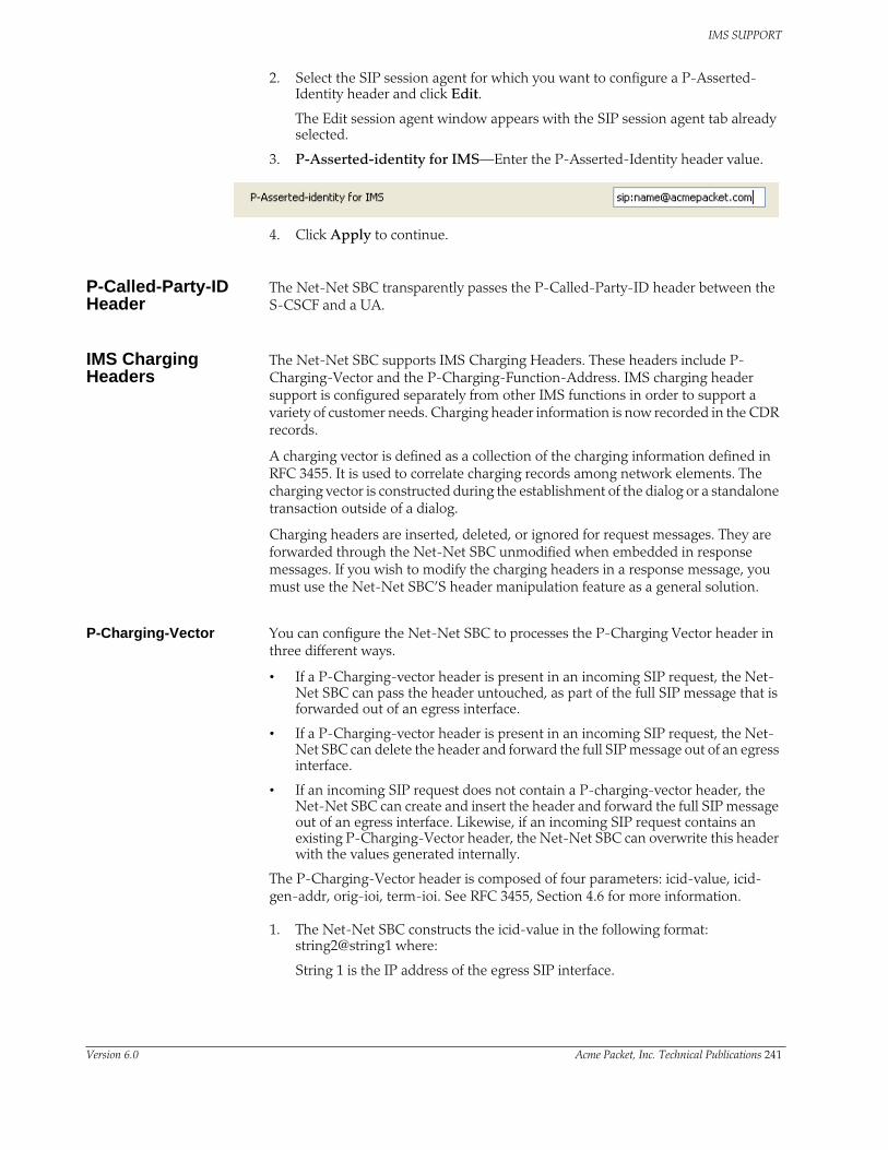
IMS SUPPORT
2. Select the SIP session agent for which you want to configure a P-Asserted-Identity header and click Edit.
The Edit session agent window appears with the SIP session agent tab already selected.
3. P-Asserted-identity for IMS—Enter the P-Asserted-Identity header value.
4. Click Apply to continue.
P-Called-Party-ID Header
The Net-Net SBC transparently passes the P-Called-Party-ID header between the S-CSCF and a UA.
IMS Charging Headers
The Net-Net SBC supports IMS Charging Headers. These headers include P-Charging-Vector and the P-Charging-Function-Address. IMS charging header support is configured separately from other IMS functions in order to support a variety of customer needs. Charging header information is now recorded in the CDR records.
A charging vector is defined as a collection of the charging information defined in RFC 3455. It is used to correlate charging records among network elements. The charging vector is constructed during the establishment of the dialog or a standalone transaction outside of a dialog.
Charging headers are inserted, deleted, or ignored for request messages. They are forwarded through the Net-Net SBC unmodified when embedded in response messages. If you wish to modify the charging headers in a response message, you must use the Net-Net SBC’S header manipulation feature as a general solution.
P-Charging-Vector You can configure the Net-Net SBC to processes the P-Charging Vector header in three different ways.
• If a P-Charging-vector header is present in an incoming SIP request, the Net-Net SBC can pass the header untouched, as part of the full SIP message that is forwarded out of an egress interface.
• If a P-Charging-vector header is present in an incoming SIP request, the Net-Net SBC can delete the header and forward the full SIP message out of an egress interface.
• If an incoming SIP request does not contain a P-charging-vector header, the Net-Net SBC can create and insert the header and forward the full SIP message out of an egress interface. Likewise, if an incoming SIP request contains an existing P-Charging-Vector header, the Net-Net SBC can overwrite this header with the values generated internally.
The P-Charging-Vector header is composed of four parameters: icid-value, icid-gen-addr, orig-ioi, term-ioi. See RFC 3455, Section 4.6 for more information.
1. The Net-Net SBC constructs the icid-value in the following format: string2@string1 where:
String 1 is the IP address of the egress SIP interface.
Version 6.0 Acme Packet, Inc. Technical Publications 241
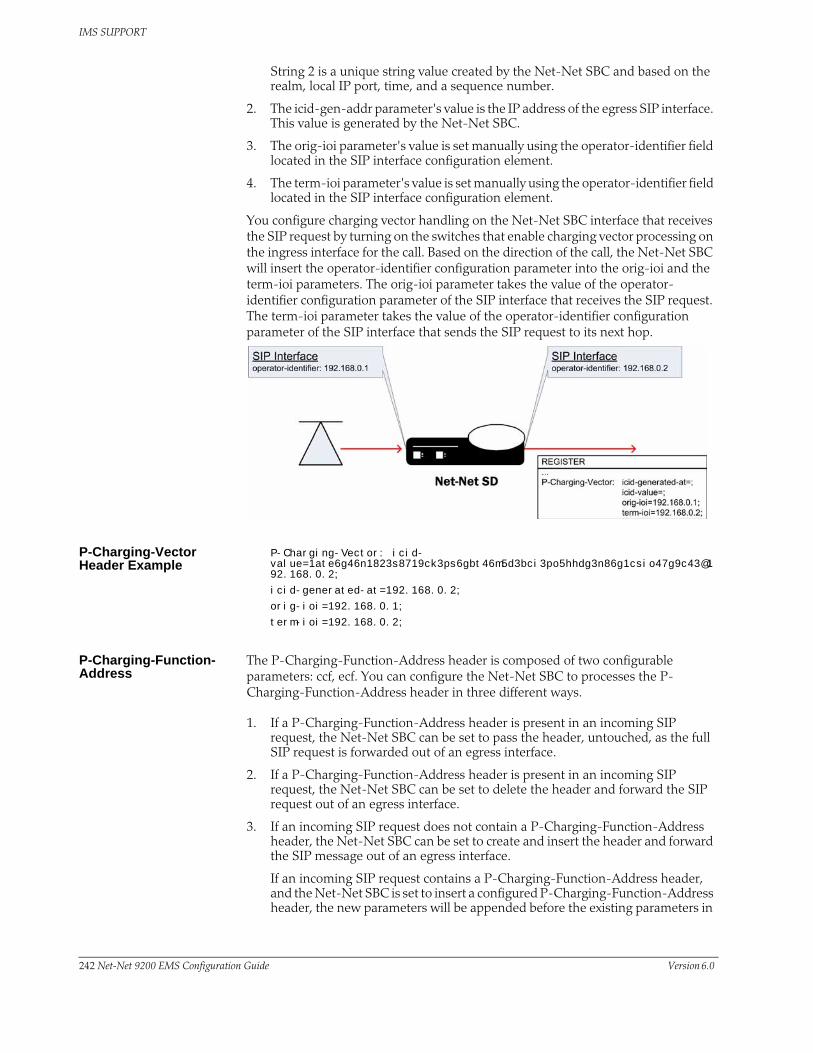
IMS SUPPORT
String 2 is a unique string value created by the Net-Net SBC and based on the realm, local IP port, time, and a sequence number.
2. The icid-gen-addr parameter's value is the IP address of the egress SIP interface. This value is generated by the Net-Net SBC.
3. The orig-ioi parameter's value is set manually using the operator-identifier field located in the SIP interface configuration element.
4. The term-ioi parameter's value is set manually using the operator-identifier field located in the SIP interface configuration element.
You configure charging vector handling on the Net-Net SBC interface that receives the SIP request by turning on the switches that enable charging vector processing on the ingress interface for the call. Based on the direction of the call, the Net-Net SBC will insert the operator-identifier configuration parameter into the orig-ioi and the term-ioi parameters. The orig-ioi parameter takes the value of the operator-identifier configuration parameter of the SIP interface that receives the SIP request. The term-ioi parameter takes the value of the operator-identifier configuration parameter of the SIP interface that sends the SIP request to its next hop.
P-Charging-Vector Header Example
P-Charging-Vector: icid-value=1ate6g46n1823s8719ck3ps6gbt46m5d3bci3po5hhdg3n86g1csio47g9c43@192.168.0.2;
icid-generated-at=192.168.0.2;
orig-ioi=192.168.0.1;
term-ioi=192.168.0.2;
P-Charging-Function-Address
The P-Charging-Function-Address header is composed of two configurable parameters: ccf, ecf. You can configure the Net-Net SBC to processes the P-Charging-Function-Address header in three different ways.
1. If a P-Charging-Function-Address header is present in an incoming SIP request, the Net-Net SBC can be set to pass the header, untouched, as the full SIP request is forwarded out of an egress interface.
2. If a P-Charging-Function-Address header is present in an incoming SIP request, the Net-Net SBC can be set to delete the header and forward the SIP request out of an egress interface.
3. If an incoming SIP request does not contain a P-Charging-Function-Address header, the Net-Net SBC can be set to create and insert the header and forward the SIP message out of an egress interface.
If an incoming SIP request contains a P-Charging-Function-Address header, and the Net-Net SBC is set to insert a configured P-Charging-Function-Address header, the new parameters will be appended before the existing parameters in
242 Net-Net 9200 EMS Configuration Guide Version 6.0

IMS SUPPORT
the header. The Net-Net SBC will then forward the SIP request out of an egress interface.
P-Charging-Function-Address Header Example
P-Charging-Function-Address: ccf=192.168.0.20;ecf=192.168.0.21
RADIUS Accounting of Charging Headers
When the Net-Net SBC creates a either the P-Charging-Vector header or the P-Charging-Function-Address header, it inserts an entry in the RADIUS record to record the charging header data.
For a P-Charging-Vector header, the icid-value is saved to the P-Charging-Vector attribute in the radius record. If the Net-Net SBC does not create a P-Charging-Vector header, but it receives a SIP message that already has the P-Charging-Vector header with an icid-value, the existing icid-value is written to the RADIUS record.
For a P-Charging-Function-Address header, the first CCF value is saved to the P-Charging-Function-Address attribute. When the Net-Net SBC creates the P-Charging-Function-Address, the CCF value it inserts into the header is saved to the radius record. If the Net-Net SBC does not create a P-Charging-Function-Address header, but it receives a SIP message that already has the P-Charging-Function-Address with a CCF value, the existing CCF value is written to the RADIUS record..
Configuring P-Charging-Vector Processing for SIP Interfaces
This section explains how to configure P-Charging-Vector processing using the Net-Net EMS.
1. Click Realms in the Net-Net EMS navigation tree.
The Realm window appears in the display pane.
2. Select the SIP realm for which you want to configure P-Charging-Vector support and click Edit. The Edit Realm window appears.
3. Select the Services/Protocols tab.
4. Select the SIP realm service for which you want to configure P-Charging-Vector support and click Edit. The Edit SIP service window appears with the SIP interface tab already selected.
5. Action to be performed on P-Changing-Vector header—Choose insert from the drop-down list.
Name Value Value Type
Acme-Session-Charging-Vector 54 string
Acme-Session-Charging-Function-Address 55 string
Version 6.0 Acme Packet, Inc. Technical Publications 243

IMS SUPPORT
6. Action to be performed on P-Changing-Function-Address header—Choose insert from the drop-down list.
7. Changing collection function (CCF) address—Enter the CCF string.
8. Eveng changing function (ECF) address—Enter the ECF string.
9. Operator ID—Enter the operator identifier string. This string must begin with an alpha character.
10. Click Apply.
SIP Charging Function Address Enhancements for IMS
The Net-Net SBC’s handling for the 3GPP P-Charging-Function-Address (PCFA) header has been augmented to allow this header, found in REGISTER responses and dialog-creating or stand-alone messages, to be cached.
There are two values you can set for the Action to be performed on P-Charging-Function-Address header parameter in the ingress SIP interface configuration:
• insert-reg-cache—To be configured on the SIP interface facing the UE, this value configures the Net-Net SBC to replace the PCFA with the most recently cached values rather than the Charging collection function (CCF) address and Event charging function (ECF) address you set to be static in your configuration. The cached values come from one of the following that the Net-Net SBC has received most recently:
• Request and response messages for the same dialog
• Registration cache entry
• Local configuration (statically configured in Charging collection function (CCF) address and Event charging function (ECF) address parameters)
• delete-and-respond—To be configured on the SIP interface facing the S-CPCF, this value configures the Net-Net SBC to strip out the latest cached PCFA, and then cache the latest PCFA from responses.
Notes on Prior Behavior
In order to introduce these two new modes, the Net-Net SBC’s prior behavior has been modified slightly. Formerly, the PCFA header was counted in RADIUS CDRs for all responses; however, since responses can come from a UE, this behavior can result in updating accounting information with untrusted headers. The Net-Net SBC no longer behaves in this way. In addition, accounting record information can now be updated during a session for PCFA functions.
244 Net-Net 9200 EMS Configuration Guide Version 6.0

IMS SUPPORT
How It Works This section describes how PCFA insertion and caching work on the Net-Net SBC. The following diagram shows how this feature can be configured to strip PCFAs out of messages from UEs, and to use core PCFAs in communications with the core.
PCFA Insertion Using the two new settings, the Net-Net SBC adds the PCFA to all SIP requests and to the response on the S-CPCF facing the SIP interface. However, only dialog-creating and standalone requests, and responses to each of those, update the Net-Net SBC and accounting information. Such requests do not have a To tag, and responses do not appear in established dialogs. The Net-Net SBC inserts the PCFA into provisional (1XX) and success (2XX) responses, with the exception of the 100 Trying response.
You can use SIP header manipulation rules (HMR) to remove any unwanted headers.
PCFA Caching When you use either of the new configuration parameters, the Net-Net SBC uses the latest cached copy of a PCFA header to insert into requests and responses. The Net-Net SBC does not cache any PCFA headers it receives on SIP interfaces using the none, insert, or insert-reg-cache modes because this type of SIP interface faces the UE making its replacement headers ones from the core.
Though there can be various sources for the latest cached copy, the PCFA header received as part of a dialog-creating or standalone request has highest precedence. This PCFA header is then stored as the latest cached value for that dialog. That is, for each specific dialog, the Net-Net SBC the PCFA is cached separately so it can add the most specific PCFA to the message—and is added to any message for the dialog.
When there is no cache PCFA for a specific dialog, the Net-Net SBC uses the registration cache entry as the latest cached copy. And when there is no entry in the registration, the PCFA uses the CCF address and ECF address values from the SIP interface.
The latest cached copy or the CCF address is the value reported in the RADIUS VSA Acme-Session-Charging-Function-Address; this VSA is used for both of the new modes. Note that only the CCF address is reported in RADIUS records; the ECF address is not.
Version 6.0 Acme Packet, Inc. Technical Publications 245

IMS SUPPORT
Configuring SIP Charging Function Address Enhancements
For this feature to work as designed, you need to configure:
• The UE-facing SIP interface with a Action to be performed on P-Charging-Function-Address header value of insert-reg-cache
• The core-facing SIP interface with a Action to be performed on P-Charging-Function-Address header value of delete-and-respond
To set the charging function address mode:
1. Click Realms in the Net-Net EMS navigation tree. The Realm table appears in the display pane.
2. Click a SIP realm in the table to select it.
3. Click Edit. The Edit Realm window appears.
4. Click the Services/Protocols tab. The Realm services table appears.
5. Click the name of the realm to which you want to apply SIP route header removal in the table.
6. Click Edit. The Edit SIP service window appears.
7. Action to be performed on P-Charging-Function-Address header—Choose the charging function address mode you want to use. from the drop-down list.
• none—Pass the P-Charging-Vector header received in an incoming SIP message untouched as the message is forwarded out of the Net-Net SBC, but does not include icid-value in accounting records
• pass—Pass the P-Charging-Vector header received in an incoming SIP message untouched as the message is forwarded out of the Net-Net SBC, includes icid-value in accounting records
• delete—Delete the P-Charging-Vector header received in an incoming SIP message before it is forwarded out of the Net-Net SBC
• insert—Inserts the P-Charging-Vector header in an incoming SIP message that does not contain the P-Charging-Vector header. If the incoming message contains the P-Charging-Vector header, the Net-Net SBC will
246 Net-Net 9200 EMS Configuration Guide Version 6.0

IMS SUPPORT
overwrite the P-Charging-Vector header with its values. This option always uses the CCF address and ECF address static values.
• insert-reg-cache—To be configured on the SIP interface facing the UE, configures the Net-Net SBC to replace the PCFA with the most recently cached value rather than the CCF address and ECF address you set to be static in your configuration. The cached values come from one of the following that the Net-Net SBC has received most recently: request, response, registration, or local configuration.
• delete-and-respond—To be configured on the SIP interface facing the S-CPCF, configures the Net-Net SBC to strip out the latest cached PCFA from the core side. The Net-Net SBC then remembers this PCFA and uses it in communications sent to the core.
Note that the default settings for this parameter and for Action to be performed on P-Charging-Vector heading are pass for new SIP interface configurations. If you are upgrading and there are pre-existing SIP interfaces in your configuration, the defaults become none.
8. Click Apply.
P-Visited-Network-ID Header
The Net-Net SBC’S IMS support also includes the insertion of a P-Visited-Network-ID header into SIP messages when applicable. When a UE sends a dialog-initiating request (e.g., REGISTER or INVITE message) or a standalone request outside of a dialog (e.g., OPTIONS) to the P-CSCF, the Net-Net SBC inserts the P-Visited-Network-ID header into the SIP message as it enters into the destination network.
The P-Visited-Network ID header will be stripped from SIP messages forwarded into untrusted networks as expected. The content of a P-Visited-Network-ID header is a text string that identifies the originating UE's home network. This string is user-configurable.
Version 6.0 Acme Packet, Inc. Technical Publications 247

IMS SUPPORT
Configuring P-Visited-Network-ID Header Handling for SIP Interfaces
This section explains how to configure P-Visited-Network-ID header handling using the Net-Net EMS. Before performing the following procedures, you must enable IP multi-media subsystem.
1. Click Realms in the Net-Net EMS navigation tree.
The Realm window appears in the display pane.
2. Select the SIP realm for which you want to configure P-Visited-Network-ID header support and click Edit. The Edit Realm window appears.
3. Select the Services/Protocols tab.
4. Select the SIP realm service for which you want to configure P-Visited-Network-ID header support and click Edit. The Edit SIP service window appears with the SIP interface tab already selected.
5. Enable IP multi-media subsystem—Click the checkbox, if it has not already been checked, to enable IMS processing on this SIP interface.
6. Network ID—Enter the network ID string.
7. Click Apply.
Implicit Service Route In an IMS architecture, the Service-Route header indicates the network's requirement for where to direct all subsequent signaling from a given UE. Upon receipt of the Service-Route header(s) in a 200 OK response to a REGISTER request, the Net-Net SBC stores the values contained therein and preloads them when issuing new requests (such as an INVITE or a SUBSCRIBE) from the associated endpoint.
Although not all SIP networks fully support RFC 3608, some still require UEs to send all call traffic to the network element(s) with which they originally registered. Further, some P-CSCFs do not pass back the Service-Route headers in response to the UE's REGISTER request. This situation requires that a logical connection is made between the UE and the network element to which it registers.
In these scenarios, the Net-Net SBC may create an implicit Service-Route for the success (2xx class) response it receives from the P-CSCF. An implicit Service-Route is useful for creating a binding between a UE and a next-hop proxy, even when the Net-Net SBC can route to many potential, yet logically equivalent next-hops.
248 Net-Net 9200 EMS Configuration Guide Version 6.0

IMS SUPPORT
The Net-Net SBC's implicit Service-Route feature is enabled with the implicit-service-route parameter. It is configured on the access-side SIP interface where a UE registers.
Enabling Implicit Service-Route Support
This section explains how to enable implicit service-routing on your Net-Net EMS.
1. Click Realms in the Net-Net EMS navigation tree.
The Realm window appears in the display pane.
2. Select the SIP realm for which you want to configure P-Visited-Network-ID header support and click Edit. The Edit Realm window appears.
3. Select the Services/Protocols tab.
4. Implicit service routing—Select enabled from the drop-down list. The following are valid values for this parameter:
– enabled—Implicit service routing is enabled.
– disabled—Implicit service routing is disabled.
– strict—Implicit service routing is enabled, but the loose route parameter will not be inserted in the Route URI of the implicit service route for requests sent to the proxy.
5. Click Apply.
Version 6.0 Acme Packet, Inc. Technical Publications 249

IMS SUPPORT
P-CSCF Redundancy with Implicit Service RouteYou can configure multiple P-CSCFs in a core network to provide redundant P-CSCF functionality. Configuring multiple P-CSCFs is performed similarly to configuring any type of redundant session agent (SA), either through DNS for a single SA or with a session agent group (SAG). If an SA (or member of an SAG) goes out of service, and the IP address is unreachable, the Net-Net SBC uses the next IP address for the SA (or member of an SAG). Also the Net-Net SBC can load balance P-CSCFs by using a load balancing SAG strategy such as round-robin.
Tracking UE per P-CSCF
To ensure continuity of service, the Net-Net SBC tracks the relationship between a UE and the P-CSCF it registers to. When a P-CSCF goes out of service and fails over to the next P-CSCF (as an SA or member of an SAG), the Net-Net SBC notes the time of the failover event. When a UE associated with the failed P-CSCF re-registers, the Net-Net SBC sees that the previous P-CSCF has experienced a failover. Upon a P-CSCF failover, the Net-Net SBC redirects the associated UE's traffic to the new P-CSCF as the registrar/proxy.
To configure the Net-Net SBC to direct a UE to use a P-CSCF that has been placed in service after the previous P-CSCF failed, use the parameter that enables the implicit service-route feature as described in the previous section.
Registration Invalidation
The Net-Net SBC includes provisions to explicitly invalidate current registrations in certain instances. If the P-CSCF (configured as a SA) goes out of service, or if the active IP address that specifies a P-CSCF does not point to the active P-CSCF, the Net-Net SBC can invalidate the current endpoint registrations to that SA. The new configuration, when enabled, forces the Net-Net SBC to act as if the registrations have expired, thus forcing the endpoints to re-register. The Net-Net SBC responds back to the registering endpoint with a 403 response (if the allow-anonymous parameter in the sip-ports configuration element is set to registered).
Enabling Registration Invalidation Support
This section explains how to enable registration invalidation support.
1. Click Session agents in the Net-Net EMS navigation tree.
The Session Agent window appears in the display pane with a table displaying all configured session agents saved on the Net-Net SBC.
2. Select the SIP session agent for which you want to enable registration invalidation support and click Edit.
The Edit session agent window appears with the SIP session agent tab already selected.
250 Net-Net 9200 EMS Configuration Guide Version 6.0

IMS SUPPORT
3. Invalidate registrations—Select enabled from the drop-down list.
4. Click Apply.
Contact Header Contact FormattingSome P-CSCF implementations require an extra parameter in the Contact header of the register message for full compatibility. This parameter should contain the public IP address of the UE.
The contact-firewall option is configured on the SIP interface attached to the core network.
When entering the contact-firewall option without a value, the Net-Net SBC will add a parameter to the Contact header called firewall. The value will be IPaddress:port. Note the appearance of the contact header in the following example and how it includes the endpoint’s public IP address.
To change the parameter name from "firewall" to a name of your choosing, enter the option as contact-firewall="parameter_name".
Adding a UE’s public IP address and port to the contact header
This section explains how to add a UE’s public IP address and port to the contact header.
1. Click Realms in the Net-Net EMS navigation tree.
The Realm window appears in the display pane.
2. Select the SIP realm for which you want to configure P-Visited-Network-ID header support and click Edit. The Edit Realm window appears.
3. Select the Services/Protocols tab.
Version 6.0 Acme Packet, Inc. Technical Publications 251

IMS SUPPORT
4. Select the SIP realm service you want to configure and click Edit. The Edit SIP service window appears.
5. Click the Options button.
The Options window appears.
6. Select the contact-firewall option and click the right arrow. The option is moved to the Selected options box.
7. Click OK.
252 Net-Net 9200 EMS Configuration Guide Version 6.0

IMS SUPPORT
SIP IMS and PrivacyIn order to determine the trust level on the ingress side correctly, you need to set the ppi-to-pai parameter in the SIP interface configuration. If the sip-ims-feature parameter is enabled on the incoming SIP interface, then the Net-Net SBC applies the IMS rules for determining PAI. And if the PAI is based on the IMS processing, the PPI will be removed. Otherwise, the Net-Net SBC removes the PPI unless you:
• Set the ingress SIP interface’s ppi-to-pai parameter to the replace mode
• Set the ingress SIP interface is designated as trusted and ppi-to-pai is also set to trusted
The egress processing of this parameter is applied if the PPI is not removed.
On the egress SIP interface, the Net-Net SBC checks the ppi-to-pai parameter only if the message’s destination is designated trusted. If the destination is untrusted, then the Net-Net SBC does not reference this parameter.
There are four valid values for the ppi-to-pai parameter:
• none—The Net-Net SBC performs no conversion
• trusted—The Net-Net SBC checks the configured trust level for the ingress endpoint; if is it untrusted, then PPI headers in the message are deleted; if it is trusted, then PPIs are converted to PAIs
• remove—The Net-Net SBC removes PPI headers
• always—The Net-Net SBC always converts PPIs to PAIs
Setting the PPI to PAI Conversion Mode
This section explains how to set the PPI to PAI conversion mode.
1. Click Realms in the Net-Net EMS navigation tree.
The Realm window appears in the display pane.
2. Select the SIP realm for which you want to configure PPI to PAI conversion and click Edit. The Edit Realm window appears.
3. Select the Services/Protocols tab.
4. Select the SIP realm service you want to configure and click Edit. The Edit SIP service window appears.
5. Preferred/Asserted identification conversion mode—Select the conversion mode you want to use from the drop-down list.
6. Click Apply.
Version 6.0 Acme Packet, Inc. Technical Publications 253

IMS SUPPORT
254 Net-Net 9200 EMS Configuration Guide Version 6.0

8 NAT ALG Services
IntroductionThis chapter describes the Net-Net SBC’s NAT ALG services. The Net-Net SBC supports Network Address and Port Translation (NAPT) and Trivial File Transfer Protocol (TFTP) functionality over media interfaces, collectively known as Network Address Translation (NAT) ALG. The NAT ALG feature is implemented as an extension of the static flow feature and is configured with seven new parameters.
In some applications, the Net-Net SBC acts as an intermediary device, positioned between endpoints located in an access network and application servers located in a backbone network. The Net-Net SBC’s NAT ALG feature enables these endpoints to use non-VoIP protocols, such as TFTP and HTTP, to access servers in a provider’s backbone network to obtain configuration information.
NAT ALG parameters support RTC and can be dynamically reconfigured. The active NAT ALG configuration can be replicated on the standby Net-Net SBC in an HA configuration.
NAPT The NAPT ALG functionality is the same as that found in commercially available enterprise and residential NAT devices. The Net-Net SBC watches for packets entering a media interface that match source and destination IP address criteria. Matching packets are then redirected out of the egress interface, through a specified port range, toward a destination address.
TFTP The TFTP ALG is implemented as an extension of the NAT ALG. It works slightly differently than traditional NAPT. In a TFTP session, the first packet is sent from a source endpoint to port 69 on the TFTP server. The TFTP server responds from another port. This port, from which the TFTP response originates, is used for the remainder of the TFTP session.
SDCLIENT SERVER
source
ingressinterface
egressinterface
destination
Version 6.0 Acme Packet, Inc. Technical Publications 251

NAT ALG SERVICES
To act as a TFTP ALG, the Net-Net SBC will latch on the first return packet from the server to learn the server's port. The ingress-side destination port of the Net-Net SBC is changed to reflect the new communications port for the TFTP session. This process takes place without any user intervention.
Configuring the NAPT ALG
This section explains how to configure the NAPT ALG. Configuring the NAPT ALG occurs within the static flow configuration element.
1. Click Static Flows in the Net-Net EMS navigation tree.
The Static flow window appears in the display pane.
2. Select the static flow you want to configure and click Edit.
The Edit Static flow window appears.
CLIENT SERVER
client sends toserver at port69
server respondswith a port of itsselection, whichis used for therest of thesession
9200CLIENT SERVER
source
ingress interface
egress interface
destination
252 Net-Net 9000 EMS Configuration Guide Version 6.0

NAT ALG SERVICES
3. Protocol—Select the protocol this NAPT ALG acts upon from the drop-down list. Valid values are: TCP, UDP, ICMP, ALL.
4. ALG type—Select NAPT from the drop-down list to create a NAPT ALG.
5. Realm—Select the defined source realm where traffic for this NAT ALG originates in the To Realm section of the screen.
6. Source—Enter the network that defines where the incoming traffic originates.
7. Destination—Enter the ingress side’s destination. This is the IP address and port of the network interface in the ingress realm..
8. Realm—Select the defined realm where traffic leaving this NAT ALG exits the Net-Net SBC.
9. Source—Enter the egress IP address. This is the IP address of the network interface where traffic subject to the NAT ALG you are defining leaves the Net-Net SBC.
10. Destination—Enter the IP address and port number of the server or other destination this NAPT ALG redirects traffic toward.
11. Flow Policing—Click the checkbox to limit the bandwidth of this ALG service.
Version 6.0 Acme Packet, Inc. Technical Publications 253

NAT ALG SERVICES
12. Maximum bandwidth allowed per flow—Enter the maximum bandwidth per flow for this ALG service.
13. Start port—Enter the beginning port number of the port range that the Net-Net SBC allocates on the egress side for flows that this NAPT ALG redirects.
14. End port—Enter the ending port number of the port range that the Net-Net SBC allocates on the egress side for flows that this NAPT ALG redirects.
15. Flow time limit—Enter the total time limit for an NAPT flow in seconds.
16. Initial guard timer—Enter the initial guard timer value in seconds.
17. Subsequent guard timer—Enter the subsequent guard timer value in seconds.
18. Click Apply.
Configuring the TFTP ALG
This section explains how to configure the TFTP ALG. The TFTP ALG configuration occurs in the static flow configuration element.
1. Click Static Flows in the Net-Net EMS navigation tree.
The Static flow window appears in the display pane.
2. Select the static flow you want to configure and click Edit.
The Edit Static flow window appears.
254 Net-Net 9000 EMS Configuration Guide Version 6.0

NAT ALG SERVICES
3. Protocol—Select the protocol this TFTP ALG acts upon from the drop-down list. Valid values are: TCP, UDP, ICMP, ALL.
4. ALG type—Select TFTP from the drop-down list to create a TFTP ALG.
5. Realm—Select the defined source realm where traffic for this TFTP ALG originates in the To Realm section of the screen.
6. Source—Enter the network that defines where the incoming traffic originates.
7. Destination—Enter the ingress side’s destination. This is the IP address and port of the network interface in the ingress realm..
8. Realm—Select the defined realm where traffic leaving this TFTP ALG exits the Net-Net SBC.
9. Source—Enter the egress IP address. This is the IP address of the network interface where traffic subject to the TFTP ALG you are defining leaves the Net-Net SBC.
10. Destination—Enter the IP address and port number of the server or other destination this TFTP ALG redirects traffic toward.
11. Flow Policing—Click the checkbox to limit the bandwidth of this ALG service.
Version 6.0 Acme Packet, Inc. Technical Publications 255

NAT ALG SERVICES
12. Maximum bandwidth allowed per flow—Enter the maximum bandwidth per flow for this ALG service.
13. Start port—Enter the beginning port number of the port range that the Net-Net SBC allocates on the egress side for flows that this TFTP ALG redirects.
14. End port—Enter the ending port number of the port range that the Net-Net SBC allocates on the egress side for flows that this TFTP ALG redirects.
15. Flow time limit—Enter the total time limit for an TFTP flow in seconds.
16. Initial guard timer—Enter the initial guard timer value in seconds.
17. Subsequent guard timer—Enter the subsequent guard timer value in seconds.
18. Click Apply.
256 Net-Net 9000 EMS Configuration Guide Version 6.0

9 Session Routing and Load Balancing
IntroductionThis chapter explains how to configure session routing and load balancing for SIP services. It contains information about configuring session agents and session agent groups, as well as local policies that can be used for routing SIP signals.
Routing Overview This section provides an overview of routing SIP sessions when using the Net-Net SBC. The Net-Net SBC chooses the next hop through the network for each SIP session based on information received from routing policies and constraints. Routing policies can be as simple as routing all traffic to a proxy or routing all traffic from one network to another. Routing policies can also be more detailed, using constraints to manage the volume and rate of traffic that can be routed to a specific network. For example, you can manage volume and rate of traffic to enable the Net-Net SBC to load balance and route around softswitch failures.
When a call request arrives at the Net-Net SBC, a decision making process then occurs to determine whether the message is coming from a session agent. If so, the Net-Net SBC checks whether that session agent is authorized to make the call. Local policy is then checked to determine where to send the message on to.
Session Agents, Session Groups, and Local Policy
You can use session agents, session agent groups and local policies to define routing. However, using session agents and session agent groups is not required.
• session agent: defines a signaling endpoint. It is a next hop signaling entity that can be configured to apply traffic shaping attributes.
• session agent group (SAG): can contain individual session agents and other session agent groups. Members of a SAG are logically equivalent (although they might vary in their individual constraints) and can be used interchangeably.
You apply an allocation strategy to the SAG to allocate traffic across the group members. Session agent groups also assist in load balancing among session agents.
• local policy: indicates where session request messages, such as SIP INVITES, are routed and/or forwarded. You use a local policy to set a preference for selecting one route over another.
Another element of routing is the realm. Realms are used when a Net-Net SBC communicates with multiple network elements over a shared intermediate connection. Defining realms allows sessions to go through a connection point between the two networks. See Configuring Realms for additional details.
Version 6.0 Acme Packet, Inc. Technical Publications 257

SESSION ROUTING AND LOAD BALANCING
When you configure a realm, you give it an identifier, which stores the name of the realm associated with the Net-Net SBC. The realm identifier value is also needed when you configure session agents and local policies. You can associate a realm with a session agent to identify the realm for sessions coming from or going to the session agent. You also need the realm identifier when you configure local policy to identify the egress realm (realm of the next hop).
About Session AgentsA session agent defines a signaling endpoint. It is a next hop signaling entity that can be configured to apply traffic shaping attributes. Service elements such as gateways, softswitches, and gatekeepers are defined automatically within the Net-Net SBC as session agents. For each session agent, concurrent session capacity and rate attributes can be defined. You can group session agents together into session agent groups and apply allocation strategies to achieve traffic load balancing.
You can configure a set of attributes and constraints for each session agent to support the following:
• Session access control—Net-Net SBC only accepts requests from configured session agents
• Session admission control (concurrent sessions)—Net-Net SBC limits the number of concurrent inbound and outbound sessions for any known service element
• Session agent load balancing—Session agents are loaded based on their capacity and the allocation strategy specified in the session agent group
• Session (call) gapping—Net-Net SBC polices the rate of session attempts to send to and receive from a specific session agent
SIP Session Agents
SIP session agents can include the following:
• softswitches
• SIP proxies
• application servers
• SIP gateways
• SIP endpoints
In addition to functioning as a single logical next hop for a signaling message (for example, where a SIP INVITE is forwarded), session agents can provide information about next or previous hops for packets in a SIP agent, including providing a list of equivalent next hops.
You can use the session agent to describe one or more SIP next or previous hops. Through the configured carriers list, you can identify the preferred carriers to use for traffic coming from the session agent. This set of carriers will be matched against the local policy for requests coming from the session agent. You can also set constraints for specific hops.
258 Net-Net 9200 EMS Configuration Guide Version 6.0

SESSION ROUTING AND LOAD BALANCING
Managing Session Agent Traffic
The Net-Net SBC monitors availability, session load, and session rate for each session agent in real time. The session agent’s state is determined by its performance relative to the constraints applied to it and its availability.
The following table lists the conditions that cause the Net-Net SBC to suspend the routing of traffic to a session agent, along with the criteria for restoring the route.
About Session Agent Groups
Session agent groups can contain individual session agents and other session agent groups. Members of a session agent group are logically equivalent (although they might vary in their individual constraints) and can be used interchangeably. You can apply allocation strategies to session agent groups.
Examples of session agent groups include the following:
• application server cluster
• media gateway cluster
• softswitch redundant pair
• SIP proxy redundant pair
• gatekeeper redundant pair
Session agent group members do not need to reside in the same domain, network, or realm. The Net-Net SBC can allocate traffic among member session agents regardless of their location. It uses the allocation strategies configured for a SAG to allocate traffic across the group members.
Constraint Condition SIP Criteria Action Criteria for Resuming
Maximum sessions exceeded
Maximum concurrent SIP sessions exceeded.
Session agent is declared in constraint violation state.
Concurrent sessions drop below the maximum sessions value.
Maximum outbound sessions exceeded
Maximum concurrent outbound SIP sessions exceeded.
Session agent is declared in constraint violation state.
Concurrent sessions drop below the maximum outbound sessions value.
Maximum burst rate exceeded
Maximum burst rate exceeded in current window.
Session agent is declared in constraint violation state.
Burst rate in subsequent window drops below maximum burst rate.
Maximum sustained rate exceeded
Maximum sustained rate exceeded in current window.
Session agent is declared in constraint violation state.
Sustained rate in subsequent window drops below the maximum sustained rate.
Session agent unavailable or unresponsive
SIP transaction expire timer expires for any out-of-dialogue request. For example, INVITE, REGISTER, or ping.
Session agent is declared in constraint violation state or out-of-service. The time to resume timer starts.
Time to resume timer expires and the Net-Net SBC declares the session agent in-service.orSession agent responds to subsequent pings (SIP only).
Version 6.0 Acme Packet, Inc. Technical Publications 259

SESSION ROUTING AND LOAD BALANCING
Allocation strategies include the following:
You apply allocation strategies to select which of the session agents that belong to the group should be used. For example, if you apply the Hunt strategy session agents are selected in the order in which they are listed.
About Local PolicyLocal policy lets you indicate where session requests, such as SIP INVITES, should be routed and/or forwarded. You use a local policy to set a preference for selecting one route over another. The local policy contains the following information that affects the routing of the SIP signaling messages:
• Information in the From header
Information in the message’s From header is matched against the entries in the local policy’s from address parameter to determine if the local policy applies.
• List of configured realms
This list identifies from what realm traffic is coming and is used for routing by ingress realm. The source realms identified in the list must correspond to the valid realm IDs you have already configured
• Local policy attributes
The attributes serve as an expression of preference, a means of selecting one route over another. They contain information such as the next signaling address to use (next hop) or whether you want to select the next hop by codec, the realm of the next hop, and the application protocol to use when sending a message to the next hop. You can also use the attributes to filter specific types of traffic.
Allocation Strategy Description
Hunt Net-Net SBC selects the session agents in the order in which they are configured in the SAG. If the first agent is available, and has not exceeded any defined constraints, all traffic is sent to the first agent. If the first agent is unavailable, or is in violation of constraints, all traffic is sent to the second agent. And so on for all session agents in the SAG. When the first agent returns to service, the traffic is routed back to it.
Round robin Net-Net SBC selects each session agent in the order in which it is configured, routing a session to each session agent in turn.
Least busy Net-Net SBC selects the session agent with the least number of active sessions, relative to the maximum outbound sessions or maximum sessions constraints (lowest percent busy) of the session agent.
Proportional distribution Session agents are loaded proportionately based upon the respective maximum session constraint value configured for each session agent.
Lowest sustained rate Net-Net SBC routes traffic to the session agent with the lowest sustained session rate, based on observed sustained session rate.
260 Net-Net 9200 EMS Configuration Guide Version 6.0

SESSION ROUTING AND LOAD BALANCING
Routing Calls by Matching Digits
Local policy routing of a call can be based on matching a sequence of digits against what is defined in the local policy. This sequence refers to the first digits in the (phone) number, matching left to right.
The following examples show how the Net-Net SBC matches an area code or number code against configured local policies.
• If the number or area code being matched is 1234567 (where 123 is an area code), and the from address value in one local policy is 123, and the from address value in another local policy is 12, the Net-Net SBC forwards the call to the server that is defined as the next hop in the local policy with 123 as the from address value.
• If the number or area code being matched is 21234, and the from address value in one local policy is 123, and the from address value in another local policy is 12, the Net-Net SBC will not find a match to either local policy because the first character of the number or area code must match the first character in a from address or to address field.
The following examples show how the Net-Net SBC matches an area or number code against different local policies: the first one has a From address value of 12 and the second has a From address value of 123. The Net-Net SBC chooses the route of the local policy that is configured with the most digits matching the area or number code in its From address and To address fields.
• When the two different local policies route to two different servers, and the area or number code being matched is 123, the Net-Net SBC selects the second local policy based on the From address value of 123.
• When the two different local policies route to two different servers, and the area or number code being matched is 124, the Net-Net SBC selects the first local policy based on the From address value of 12.
Route Preference The Net-Net SBC builds a list of possible routes based on the source realm and the From-address (From-URI) and To-address (Request-URI), which forms a subset from which preference then decides. Any local policy routes currently outside of the configured time/day are not used, if time/day are set. Also, any local policy routes not on the list of carriers (if carriers is set and the requests has a Carrier header) are not used.
Note: Source realm is used in the local policy lookup process, but it is not used in route preference calculations.
SIP RoutingThis section describes SIP session routing. When routing SIP call requests, the Net-Net SBC communicates with other SIP entities, such as SIP user devices, other SIP proxies, and so on, to decide what SIP-based network resource each session should visit next. The Net-Net SBC processes SIP call requests and forwards the requests to the destination endpoints to establish, maintain, and terminate real-time multimedia sessions.
Certain items in the messages are matched with the content of the local policy, within constraints set by the previous hop session agent, and the SIP configuration information (for example, carrier preferences) to determine a set of applicable next hop destinations.
Version 6.0 Acme Packet, Inc. Technical Publications 261

SESSION ROUTING AND LOAD BALANCING
The sending session agent is validated as either a configured session agent or a valid entry in a user cache. If the session INVITATION does not match any registering user, the SIP proxy determines the destination for routing the session INVITATION.
Limiting Route Selection Options for SIP
You can configure the local policy to use the single most-preferred route. And you can configure the SIP configuration max routes option to restrict the number of routes which can be selected from a local policy lookup:
• A max-routes=1 value limits the Net-Net SBC to only trying the first route from the list of available preferred routes.
• A max-routes=0 value or no max-routes value configured in the options field allows the Net-Net SBC to use all of the routes available to it.
About Loose Routing According to RFC 3261, a proxy is loose routing if it follows the procedures defined in the specification for processing of the Route header field. These procedures separate the destination of the request (present in the Request-URI) from the set of proxies that need to be visited along the way (present in the Route header field).
When the SIP NAT’s route home proxy field is set to enabled, the Net-Net SBC looks for a session agent that matches the home proxy address and checks the loose routing field value. If the loose routing is:
• enabled: a Route header is included in the outgoing request in accordance with RFC 3261.
• disabled: a Route header is not included in the outgoing request; in accordance with the route processing rules described in RFC 2543 (referred to as strict routing). That rule caused proxies to destroy the contents of the Request-URI when a Route header field was present.
Whether loose routing field is enabled is also checked when a local policy ‘s next hop value matches a session agent. Matching occurs if the hostname or the session agent’s IP address field value corresponds to the next hop value. If loose routing is enabled for the matching session agent, the outgoing request retains the original Request-URI and Route header with the next hop address.
About the Ingress Realm
You can create a list of realms in your local policy that is used by the Net-Net SBC to determine how to route traffic. This list determines from which realm traffic is coming and is used for routing by ingress realm.
The source realm values must correspond to valid identifier entered when the realm was configured.
About the Egress Realm
An egress realm allows SIP signaling to travel out of the Net-Net SBC through a network other than the home realm. The Net-Net SBC uses egress realms for signaling purposes (when matching flows). When a packet arrives at the Net-Net SBC with a destination address that does not match any defined session agents, the Net-Net SBC uses the address associated with the realm that is, in turn, associated with the SIP configuration’s egress realm ID, as the outgoing network. With the use of the egress realm ID, it is possible to define a default route for SIP requests addressed to destinations outside the home realm. If no egress realm is defined, the home realm (default ingress realm) is used as the default egress realm.
262 Net-Net 9200 EMS Configuration Guide Version 6.0

SESSION ROUTING AND LOAD BALANCING
About SIP Redirect SIP redirect involves proxy redirect and tunnel redirect.
Proxy Redirect You can configure the SIP proxy mode to define how the SIP proxy will forward requests coming from the session agent. This value is used if the session agent’s proxy mode has no value (is empty).
Tunnel Redirect You can use tunnel redirect when requests are routed to a server behind a SIP NAT that sends redirect responses with addresses that should not be modified by the SIP NAT function. For example, a provider might wish to redirect certain calls (like 911) to a gateway that is local to a the UA that sent the request. Since the gateway address is local to the realm of the UA, it should not be modified by the SIP NAT of the server’s realm. Note that the server must have a session agent configured with the redirect-action field set to the proxy option in order to cause the redirect response to be sent back to the UA.
Load BalancingThis section describes Net-Net SBC load balancing. You can use session agent groups to assist in load balancing among session agents. You define concurrent session capacity and rate attributes for each session agent and then define the session agent group. Next, you select the allocation strategy you want applied to achieve the load balancing you want.
The following example shows a configuration for load balancing gateways based on a proportional allocation strategy.
Version 6.0 Acme Packet, Inc. Technical Publications 263

SESSION ROUTING AND LOAD BALANCING
Routing and load balancing capabilities include the following:
• least cost, which includes cost-based and time-based routing
• customer preference
• traffic aggregation
• routing by media (codec) type
• capacity-based, by destination
• service element load balancing
• service element failure detection and re-route
• session agent failure
• routing by codec
264 Net-Net 9200 EMS Configuration Guide Version 6.0

SESSION ROUTING AND LOAD BALANCING
Configuring RoutingThis section explains how to configure routing on the Net-Net EMS.
Configuration Prerequisite
You should have already configured the realms for your environment before you configure the routing elements. See Configuring Realms for details. You need to know the realm identifier when configuring session agents and local policy.
You can use an asterisk (*) when the session agent exists in multiple realms.
Configuration Order
Recommended order of configuration:
• realm
• session agent
• session agent group
• local policy
Configuration Timestamp
You might see the following information on some of the configuration windows:
This is a configuration timestamp that displays last modified information for configuration changes made using Net-Net EMS.
When you make configuration changes to elements, the Last modified by field displays the following information:
• Net-Net EMS identifier
• Name of the user that made the modification
• IP address of the host machine upon which Net-Net EMS is running
• Relevant time zone information to specify how to interpret the timestamp in the Last modified date field.
For example:
EMS_admin_172.30.80.2_UTC
The Last modified date is displayed in the string date/time format, YYYY-MM-DD HH:MM:SS. For example 2007-11-07 15:16:05. When you make configuration changes using the Net-Net EMS, the date timestamp is specified in UTC.
If a sub-element is modified the timestamp belonging to the element is updated to indicate the modification time.
Version 6.0 Acme Packet, Inc. Technical Publications 265

SESSION ROUTING AND LOAD BALANCING
Creating a Session Agent
1. Click Session agents in the Net-Net EMS navigation tree.
The Session agent window appears in the display pane.
2. Click Add. The Add Session agent window appears.
3. Name(FQDN)—Enter the FQDN in the text field. If you enter the host name as an IP address, you do not have to enter an IP address in the optional IP address parameter. If you enter the host name in FQDN format, and you want to specify an IP address, enter it in the optional IP address parameter. Otherwise you can leave the IP address parameter blank to allow a DNS query to resolve the host name.
If the initial DNS query for the session agent fails to get back any addresses, the session agent is put out-of-service. When session agent is pinged, the DNS query is repeated. The ping message is not sent until the DNS query gets back one or more IP addresses. After the query receives some addresses, the ping message is sent. The session agent remains out of service until one of the addresses responds.
Note: The value you enter here must be unique to this session agent. No two session agents can have the same hostname.
The hostnames established in the session agent populate the corresponding fields in other elements.
4. Click OK to continue. The new session agent appears in the Session agents table.
Configuring a SIP Session Agent
To configure a SIP session agent:
1. Select the SIP session agent you want to configure from the Session agents table and click Edit. The Edit Session agent window appears with the SIP session agent tab already selected.
266 Net-Net 9200 EMS Configuration Guide Version 6.0

SESSION ROUTING AND LOAD BALANCING
2. IP Adddress (required for SIP pings to test SA availability)—Enter an IP address for the hostname you entered in the Session agent name. You can leave this blank if you want DNS to resolve the name. You must include an IP address if you want to use SIP pings to contact the session agent to confirm whether it is in service.
3. Description—Enter a description of session agent.
4. State—Set the operational state of this session agent from the drop-down list.
5. Realm—Set the realm where this session agent resides from the drop-down list.
The realm ID identifies the realm for sessions coming from or going to this session agent. For requests coming from this session agent, the realm ID identifies the ingress realm. For requests being sent to this session agent, the realm ID identifies the egress realm. In a Net-Net SBC, when the ingress and egress realms are different, the media flows must be steered between the realms.
• no value: the egress realm is used unless the route (local) policy dictates otherwise
• asterisk (*): keep the egress realm based on the Request URI
6. IP port—Enter the port number where this session agent is listening.
• zero (0): if you enter zero (0), the Net-Net SBC will not initiate communication with this session agent (although it will accept calls).
• 1025 through 65535
The default value is 5060.
Note: If the transport method value is TCP, the Net-Net SBC will initiate communication on that port of the session agent.
7. Transport protocol—Set the transport protocol used to communicate with this session agent from the drop-down list.
IP Protocol Description
UDP Each UDP header carries both a source port identifier and destination port identifier, allowing high-level protocols to target specific applications and services among hosts.
UDP+TCP Allows an initial transport method of UDP, followed by a subsequent transport method of TCP if and when a failure or timeout occurs in response to a UDP INVITE. If this transport method is selected, INVITEs are always sent through UDP as long as a response is received.
DynamicTCP dTCP indicates that dynamic TCP connections are the transport method for this session agent. A new connection must be established for each session originating from the session agent. This connection is torn down at the end of a session.
Version 6.0 Acme Packet, Inc. Technical Publications 267

SESSION ROUTING AND LOAD BALANCING
8. Trusted agent—Enable this session agent as a trusted source which the Net-Net SBC checks when it receives a message to determine if the source is trusted. Values are:
9. P-Asserted identity for IMS—Enter a P-Asserted-Identity header that the Net-Net SBC will insert into any initial request for a dialog or standalone transaction sourced by the UE. The inclusion or exclusion of the P-Asserted-Identity header is dependent on the trust level of an egress realm.
SIP Message Handling 1. Scroll to SIP message handling.
2. Mode for processing requests from SA—Set the proxy mode behavior from the drop-down list. Indicate the proxy mode to use when a SIP request arrives from this session agent.
If this field is empty (upon initial runtime or upgrade), it’s value is set to the value of the SIP configuration’s proxy mode by default. If no proxy mode value was entered for the SIP configuration, the default for this field is set to proxy.
StaticTCP sTCP indicates that static TCP connections are the transport method for this session agent. Once a connection is established, it remains and is not torn down.
dynamicTLS
staticTLS
Proxy Action Description
none Session agent is not trusted.
all Session agent is trusted for all requests and responses.
trust-egress Session agent is trusted for all egress requests and responses.
trust-ingress Session agent is trusted for all ingress requests and responses.
IP Protocol Description
268 Net-Net 9200 EMS Configuration Guide Version 6.0

SESSION ROUTING AND LOAD BALANCING
The following table lists the available proxy modes along with a brief description.
3. Action upon receipt of REDIRECT from SA—Set the redirect action behavior from the drop-down list. indicate the action you want the SIP proxy to take when it receives a Redirect (3XX) response from the session agent.
If the response comes from a session agent and this field is empty (upon initial runtime or upgrade), the redirect action will be recurse. If no session agent is found (for example, if a message comes from an anonymous user agent), the redirect action is set to proxy. If the Redirect (3xx) response does not have any Contact header, the response will be sent back to the previous hop.
The following table lists the available proxy actions along with a brief description.
Note:
Options 1. Click Options next to SIP options for this SA.
The Options window appears.
2. Click the option name in the Available options list to select it.
Proxy Mode Description
Proxy If the Net-Net SBC is a Session Router, the system will proxy the request coming from the session agent and maintain the session and dialog state.If the Net-Net SBC is a Session Director, the system behaves as a B2BUA when forwarding the request.
Redirect The system sends a SIP 3xx reDIRECT response with contacts (found in the route policy) to the previous hop.
Proxy Action Description
Proxy The SIP proxy passes the response back to the previous hop; based on the proxy mode of the original request.
Recurse The SIP proxy serially sends the original request to the list of contacts in the Contact header of the response (in the order in which the contacts are listed in the response). For example, if the first one fails, the request will be sent to the second, and so on until the request succeeds or the last contact in the Contact header has been tried.
Version 6.0 Acme Packet, Inc. Technical Publications 269

SESSION ROUTING AND LOAD BALANCING
3. Click to move the option to the Selected options list. The option name appears along with a description in the Description section of the window.
4. Click OK.
5. Response code translation profile—Select the name of the response map to use for this session agent from the Response code translation profile pull-down list.
6. Local response code translation profile—Select the name of the local response map to use for this session agent from the Local response code translation profile pull-down list.
7. User part to be used in PING To header—Enter the user in the User part to be used in PING To header.
270 Net-Net 9200 EMS Configuration Guide Version 6.0

SESSION ROUTING AND LOAD BALANCING
8. User part to be used in Ping From header—Enter the user and user URI portion in the User part to be used in PING From header.
9. Manipulation ruleset for inbound messages—Select the SIP header manipulation ruleset you want to apply to SIP packets in inbound messages.
10. Manipulation ruleset for outbound messages—Select the SIP header manipulation ruleset you want to apply to SIP packets in outbound messages.
Address translations attached to session agents take precedence over address translations attached to realms. If no address translation is applied to a session agent, then the Net-Net SBC will use the address translation applied to a realm. If an address translation is applied to both a realm and session agent, the translation attached to the session agent will apply. If the applicable session agent and realm have no associated translations, then the addresses will remain in their original forms and no address translations will be performed.
11. Click Apply.
SIP Session Routing and Address Translation
To enter information in the SIP session routing & address translation tab:
1. Select the SIP session routing & address translation tab of the Edit SIP session agent window.
2. State—Select the next-hop behavior for this session agent from the drop-down list. If you retain the default value of enabled, the session agent can be used as the next hop for the route policy. If you do not want the session agent used as the next hop, enter disabled.
3. Mode—Select the loose routing behavior for this session agent from the drop-down list.
When the SIP NAT route home proxy parameter is enabled, the Net-Net SBC looks for a session agent that matches the home proxy address and checks the loose routing value. If loose routing is enabled, a Route header is included in the outgoing request in accordance with RFC 3261. If loose routing is disabled, the Route header is not included in the outgoing request (in accordance with strict routing procedures defined in RFC 2543).
The loose routing value is also checked when the local policy’s next hop value matches a session agent. If loose routing is set to enabled, the outgoing request retains the original Request-URI and Route header with the next hop address.
4. Scroll to Carriers used by SA and click Add. The Add Session agent carriers window appears.
5. Carrier name—Select the name of the carrier from the drop-down list.
Version 6.0 Acme Packet, Inc. Technical Publications 271

SESSION ROUTING AND LOAD BALANCING
6. Click OK to continue.
The new carrier code appears in the Carriers used by SA list.
Note: If this list is empty, any carrier is allowed. If it is not empty, only local policies that reference one or more of the carriers in this list will be applied to requests coming from this session agent.
7. Scroll to Incoming embedded headers to be converted to non-embedded headers and click Add. The Add Request URI headers dialog box appears.
8. Embedded headers—Enter the name of the header you want to embed. When the specified embedded header is found, the full <header=value> pair is inserted as a unique header in a redirected INVITE message that exits the Net-Net SBC.
9. Click OK.
The header name appears in the Embedded headers list.
10. Method for inserting ‘Carrier’ code from selected route into request URI—Choose a mode from the drop-down list.
You can set this parameter to let the system perform simple digit translation on calls sent to gateways. A 3-digit prefix is inserted in front of the telephone number (the Request-URI) that the gateway will use to select a trunk group. Most often, the Net-Net SBC needs to insert the carrier code into the signaling message that it sends on.
272 Net-Net 9200 EMS Configuration Guide Version 6.0

SESSION ROUTING AND LOAD BALANCING
The following table lists the available modes..
11. Inbound—Select a profile from the drop-down list..
12. Ping method—Set the Ping method from the drop-down list. The ping confirms whether the session agent is in service. If this field is left empty, no session agent will be pinged.
Setting this field value to the OPTIONS method might produce a lengthy response from certain session agents and could potentially cause performance degradation on your Net-Net SBC.
13. Ping interval (sec)—Enter the interval in seconds. The Net-Net SBC only sends the ping if no SIP transactions (have occurred to/from the session agent within the time period you enter here.
14. Click Apply.
SIP Session Agent Constraints
1. Click the SIP session agent constraints tab of the Edit Session agent window.
2. Session constraints—Click the checkbox to enable use of SIP session agent constraints.
3. Max. inbound and outbound sessions (#)—Enter the maximum number of inbound and outbound sessions.
• minimum: zero (0) is the default value and means there is no limit
• maximum: 232 -1
4. Max. outbound sessions (#)—Enter the maximum number of simultaneous outbound sessions.
• minimum: zero (0) is the default value and means there is no limit
• maximum: 232 -1
The value you enter here cannot be larger than the maximum sessions value.
5. Max. INVITE burst rate (# sessions per sec)—Enter the maximum SIP INVITE burst rate in sessions per second. This is the number of session
Carrier Mode Description
none Default value. Carrier information will not be added to the outgoing message.
URI parameter Adds a parameter to the Request-URI. For example, cic-XXX.
telephone number prefix Adds the carrier code as a prefix to the telephone number in the Request-URI (in the same manner as PSTN).
Version 6.0 Acme Packet, Inc. Technical Publications 273

SESSION ROUTING AND LOAD BALANCING
invitations allowed to be sent to or received from the session agent within the configured burst rate window value.
SIP session invitations arrive at and leave from the session agent in intermittent bursts. By entering a value in this field, you can limit the amount of session invitations that are allowed to arrive at and leave from the session agent.
For example, if you enter a value of 50 here and a value of 60 (milliseconds) for the burst rate window constraint, no more than 50 session invitations can arrive at or leave from the session agent in that 60 millisecond time frame (window). Within that 60-millisecond window, any sessions over the limit of 50 are rejected.
• minimum: zero (0) session invitations per millisecond
• maximum: 232 -1 session invitations per millisecond
6. Max. INVITE sustained rate (# sessions per sec)—Enter the maximum SIP INVITE sustained rate in sessions per second. This is the maximum rate of session invitations (per millisecond) allowed to be sent to or received from the session agent within the current window. The value you set here must be larger than the value you set for the maximum burst rate constraint.
• minimum: zero (0) invitations per millisecond
• maximum: 232 -1 invitations per millisecond
The current rate is determined by counting the number of session invitations processed within a configured time period and dividing that number by the time period. By entering a value in this field, you can limit the amount of session invitations that are allowed to arrive at and leave from the session agent over a sustained period of time.
For the sustained rate, the Net-Net SBC maintains a current and previous window size. The period of time over which the rate is calculated is always between one and two window sizes.
For example, if you enter a value of 5000 here and a value of 3600 (milliseconds) for the sustain rate window constraint, no more than 5000 session invitations can arrive at or leave from the session agent in any given 3600 millisecond time frame (window). Within that 3600-millisecond window, sessions over the 5000 limit are rejected.
7. Burst rate window (sec)—Enter a new burst rate window in seconds. The term window refers to the period of time over which the burst rate is computed. Refer to the maximum burst rate information.
The value you set here must be smaller than the value you set for the maximum burst rate constraint.
8. Sustained rate window (sec)—Enter a new sustained rate window in seconds. The value you set here must be larger than the value you set for the maximum sustain rate constraint.
• minimum: zero (0) milliseconds
274 Net-Net 9200 EMS Configuration Guide Version 6.0

SESSION ROUTING AND LOAD BALANCING
• maximum: 232 -1milliseconds
9. Max. rate of registration messages sent to SA (reg/sec)—Enter the time in seconds after which the SIP proxy should resume sending session invitations to the session agent. This value only takes effect when the SIP proxy stops sending invitations because a constraint is exceeded.
• minimum: zero (0) seconds
• maximum: 232 -1 seconds.
SIP Timers 1. After threshold reached before resuming INVITES to SA—Enter the time in seconds the SIP proxy must wait between the time an invitation is sent to an SA and the time it tries again.
2. After SA unresponsive before resuming INVITES to SA—Enter the maximum number of registration messages per second you want sent to this session agent.
3. After communication established before SA considered ‘in service’—Enter the time in seconds the session agent must be operational before it is considered in-service..
Configuring Routes
This section describes how to configure routes/local policy using the Net-Net EMS.
1. Click Routes in the Net-Net EMS navigation tree. .
The Routes window appears in the display pane.
Version 6.0 Acme Packet, Inc. Technical Publications 275

SESSION ROUTING AND LOAD BALANCING
Creating Routes 1. Click Add in the Routes window. The Add route dialog box appears.
2. To Address—Enter the To address by entering a To address value. You can use the asterisk (*) as a wildcard to indicate all this policy can be used for any destination address.
You can also use E.164 addresses (strings that contain telephone keypad characters) here. Number matching works from left to right. Formats include the following:
• SIP Request-URI
• FQDNs
• IP addresses
3. From Address—Enter the From address by entering a From address value. You can use the asterisk (*) as a wildcard to indicate this policy can be used with all originating addresses.
You can also use complete or partial E.164 addresses (strings that contain telephone keypad characters) here. Number matching works from left to right. Formats include the following:
• SIP From address
• FQDNs
• IP addresses
4. Route name—Set the Source realm from the drop-down list to determine how to route traffic. This list identifies from what realm traffic is coming and is used for routing by ingress realm by the local policy.
You can use the asterisk (*) as a wildcard to indicate this local policy can be used with all realms. Or you can enter a value that corresponds to the identifier of an already configured realm. Formats include the following:
• realm ID
• customer name
• peer name
• subdomain name
• VPN identifier
5. Next hop—Set the Next hop from the drop-down list. You can use the following as next hops:
• IP address of a specific endpoint
• Hostname or IP address of a configured session agent
• Group name of a configured session agent group
6. Destination realm—Set the Destination realm from the drop-down list. Identify the egress realm (the realm used to reach the next hop) if the Net-Net SBC must send requests out from a specific realm.
The value you enter here must correspond to a valid identifier you enter when you configured the realm. If you do not enter a value here, and the next hop is a session agent, the realm identified in the session agent configuration is used for egress.
276 Net-Net 9200 EMS Configuration Guide Version 6.0

SESSION ROUTING AND LOAD BALANCING
7. Click OK.
A confirmation message appears.
8. Click OK to save the route and clear the message. The route appears in the Route table.
Version 6.0 Acme Packet, Inc. Technical Publications 277

SESSION ROUTING AND LOAD BALANCING
Configuring Routes To configure the routes:
1. Click a route name in the table to select it and click Edit. The Edit Routes window appears.
2. State—Set the state of the local policy from the drop-down list to indicate whether you want to enable or disable the local policy.
3. Activate time—Enter the time you want the local policy to be activated using the following syntax:
yyyy:mm:dd hh:mm:ss
yyyy:mm:dd-hh:mm:ss
The default value of 0000 implies that the defined policy attributes can be considered in effect any time after 00:00:00.
4. Deactivate time—Enter the time you want the local policy to be deactivated using the following syntax:
yyyy:mm:dd hh:mm:ss
yyyy:mm:dd-hh:mm:ss
The default value of 2400 implies that the defined policy attributes can be considered in effect any time before midnight.
5. Scroll to From and click Add. The Add From address dialog box appears.
6. Address—Enter the originating address information by entering a From address value. You can use the asterisk (*) as a wildcard to indicate this policy can be used with all originating addresses. You can also use complete or partial E.164 addresses here. Number matching works from left to right. Formats include the following:
• SIP From address
• FQDNs
• IP addresses
7. Click OK. The new From address appears in the list.
8. Scroll to Request URI and click Add. The Add To address dialog box appears.
9. Address—Enter the destination address by entering a To address value. You can use the asterisk (*) as a wildcard to indicate all this policy can be used for any destination address. You can also use E.164 addresses here. Number matching works from left to right. Formats include the following:
278 Net-Net 9200 EMS Configuration Guide Version 6.0

SESSION ROUTING AND LOAD BALANCING
• SIP Request-URI
• FQDNs
• IP addresses
10. Click OK. The new Request URI address appears in the Request URI list.
11. Scroll to Source realms and click Add. The Add Source realms dialog box appears.
12. Choose a realm from the drop-down list. This list identifies from what realm traffic is coming and is used for routing by ingress realm by the local policy.
13. Click OK. The new realm name appears in the Source realm list.
14. Click Apply to save the route information.
Configuring Route Policies
To configure route policies:
1. From the Routes table, click the route you want to configure to select it.
2. Click Edit. The Edit Routes window appears.
3. Scroll to Route policies and click Add. The Add Route policy window appears.
4. Start time—Enter the time of day (from the exact minute specified) the local policy attributes go into effect. Enter only numerical characters (0-9) and follow the 4-digit military time format. For example:
1400
The default value of 0000 implies that the defined policy attributes can be considered in effect any time after 00:00:00.
5. End time—Enter the time of day (from the exact minute specified) the local policy attributes are no longer in effect. Enter only numerical characters (0-9) and follow the 4-digit military time format. For example:
2400
The default value of 2400 implies that the defined policy attributes can be considered in effect any time before midnight.
6. Click Apply. The route policy appears in the table.
Version 6.0 Acme Packet, Inc. Technical Publications 279

SESSION ROUTING AND LOAD BALANCING
7. Select the route policy and click Edit. The Edit Route policy window appears.
8. Days of week—Click the checkboxes of the days of the week you want the route policy attributes to be in effect.
9. Holidays—Click the checkbox to include holidays. The Configure button is activated.
10. Click Configure.
The Holidays window appears.
11. Click New.
The Holidays dialog box appears.
12. Date—Enter the date of the holiday in the textbox.
280 Net-Net 9200 EMS Configuration Guide Version 6.0

SESSION ROUTING AND LOAD BALANCING
13. Description—Add descriptive text in the textbox.
14. Click OK to save the information. The holiday information appears in the list.
15. Click OK to save the information and close the Holidays window.
16. Cost—Enter a cost value that acts as a unitless representation of the cost of a route relative to other routes reaching the same destination (To address). This value is used as a way of ranking policy attributes.
• minimum: zero (0)
• maximum: 999999999
The default value is zero (0).
17. Scroll to Media profiles and click Add. The Add Media profiles dialog box appears.
18. Media Profiles—Select a media profile from the drop-down list.
19. Click OK. The media profile name appears in the Media profiles list.
20. Carrier—Select a carrier from the drop-down list.
21. Scroll to Next hop.
22. Next hop—Select a session agent or session agent group to use as the next hop from the drop-down list.
23. Terminate recursion—Click the checkbox.
24. Egress realm—Select the egress realm from the drop-down list.
25. Action—Select the action to be taken from the drop-down list.
Version 6.0 Acme Packet, Inc. Technical Publications 281

SESSION ROUTING AND LOAD BALANCING
26. Engress protocol—Select the signaling protocol to use for sending traffic to the next hop from the drop-down list.
27. Click OK. The new route policy appears in the Route policies table on the Route window.
28. Click Apply.
Configuring Carriers
You can configure carriers using the Net-Net EMS.
1. Click Profiles in the Net-Net EMS navigation tree.
The Profiles window appears in the display pane.
2. Select the Carrier profile tab.
3. Click Add. The Add Carriers dialog box appears.
4. Carrier code—Enter a name for the carrier code. Carrier names are arbitrary names that can represent specific service providers or traditional PSTN telephone service providers (for sessions delivered to gateways). They are global in scope, especially if they are exchanged in TRIP. Therefore, the definition of these carriers is beyond the scope of this documentation.
You could create a list using carrier codes already defined in the North American Numbering Plan (NANP); or those defined by the local telephone number or carrier naming authority in another country.
282 Net-Net 9200 EMS Configuration Guide Version 6.0

SESSION ROUTING AND LOAD BALANCING
5. Click OK to save the new carrier and close the dialog box. The new carrier name appears in the list.
6. Click Apply.
Configuring Holidays
You can configure the holidays for which you want the route policy attributes to be in effect using the Net-Net SBC. A holiday entry must correspond with a configured holiday established in the session router.
To configure holidays:
1. Click Profiles in the Net-Net EMS navigation tree.
The Profiles window appears in the display pane.
2. Select the Carrier profile tab.
3. Select the carrier you want to configure and click Edit.
4. Scroll to Holiday dates & descriptions and click Add. The Add Holidays dialog box appears.
5. Date—Enter the date of the holiday in the textbox.
6. Description—Add descriptive text in the textbox.
7. Click OK to save the information. The holiday information appears in the list.
8. Click Apply to save the information.
Replicating Select Configuration Elements
If you have the privilege to configure an SBC, you can replicate configuration information for the following elements from one inactive configuration copy to another:
• session agents
• session agent groups
Version 6.0 Acme Packet, Inc. Technical Publications 283

SESSION ROUTING AND LOAD BALANCING
• routes
You need to ensure that all the configuration records referenced by the elements you are replicating have corresponding counterparts in the target configuration.
The target you choose for the data you’re replicating must have a matching platform (4000 or 9000), a matching configuration (standalone, HA, or PAC), and a matching version of SBC software (6.0, 9000).
Note: The existing configuration information on the target will be deleted and replaced by the replicated configuration data.
Record Validation Net-Net EMS validates that all records referenced by the data being replicated in the source configuration have corresponding records in the destination copy. For example, all realm IDs that appear as source realm values in routes being copied must already exist with the same realm ID in the destination configuration. Records include:
• session agent and session agent groups
– carriers
– inbound address translation profiles
– outbound address translation profile
– realm ID
• route
– source realm
– egress realm
– media profiles
Replicating Data To replicate data:
1. In the Inactive configurations area, right click the Net-Net SBC from which you want to replicate data. A pop-up menu appears.
2. Click Replicate. The Selective Configuration Replication console appears.
3. Target Configuration—Select the target configuration from the drop-down list.
284 Net-Net 9200 EMS Configuration Guide Version 6.0

SESSION ROUTING AND LOAD BALANCING
4. Click Start to being the replication. A warning message appears about existing data in the target configuration being deleted.
5. Click OK to proceed. The icon at the top of the window changes to indicate replication is in progress.
Net-Net EMS validates all records in the source configuration that are associated with the set of data being copied have corresponding records in the destination copy. For example, all realm IDs that appear as source realm values in routes being copied must already exist with the same realm ID in the destination configuration.
Validations for all elements are listed in the Replication log area. If validation fails, you can see which records were invalid, as well as the specific parameters within those records that cause the failure. Replication is cancelled and the target configuration is restored to it’s original state.
If validation fails, a message appears in the Replication log area
If validation is successful, all session agent, session agent, route and route policy records are deleted from the target configuration and replaced with duplicates
Version 6.0 Acme Packet, Inc. Technical Publications 285

SESSION ROUTING AND LOAD BALANCING
of the source configuration records. A message appears indicating replication was successful.
6. Click Save log if you want to save the replication log information to a file.
7. Click Close to exit the Selective Configuration Replication console.
ENUM LookupTelephone Number Mapping (ENUM from TElephone NUmber Mapping) is a suite of protocols used to unify the telephone system with the Internet by using E.164 addresses with the Domain Name System (DNS). With ENUM, an E.164 number can be expressed as a Fully Qualified Domain Name (FQDN) in a specific Internet infrastructure domain defined for this purpose (e164.arpa). E.164 numbers are globally unique, language independent identifiers for resources on Public Switched Telecommunication Networks (PSTNs). ITU-T recommendation E.164 is the international public telecommunication telephony numbering plan.
How ENUM Works ENUM uses DNS-based architecture and protocols for mapping a complete international telephone number (for example, +1 202 123 1234) to a series of Uniform Resource Identifiers (URIs).
The protocol itself is defined in the document E.164 number and DNS (RFC 3761) that provides facilities to resolve E.164 telephone numbers into other resources or services on the Internet. The syntax of Uniform Resource Identifiers (URIs) is defined in RFC 2396. ENUM uses Naming Authority Pointers (NAPTR) records defined in RFC 2915 in order to identify available ways or services for contacting a specific node identified through the E.164 number.
Translating the Telephone Number
A telephone number is translated into an Internet address using the following steps:
1. The number is first stored in the following format, +1-202-555-1234. 1 is the country code for the United States, Canada, and the seventeen other countries that make up the North American Numbering Plan (NANP). The + indicates that the number is a complete, international E.164 telephone number.
2. All characters are removed except for the digits. For example, 12025551234.
3. The order of the digits is reversed. For example, 43215552021. The telephone number is reversed because DNS reads addresses from right to left, from the most significant to the least significant character. Dots are placed between each digit. Example: 4.3.2.1.5.5.5.2.0.2.1. In DNS terms, each digit becomes a zone. Authority can be delegated to any point within the number.
4. A domain (for example, e164.arpa) is appended to the end of the numbers in order to create a FQDN. For example,4.3.2.1.5.5.5.2.0.2.1.e164.arpa.
286 Net-Net 9200 EMS Configuration Guide Version 6.0

SESSION ROUTING AND LOAD BALANCING
5. The domain name is queried for the resource records that define URIs necessary to access SIP-based VoIP.
Once the authoritative name server for that domain name is found, ENUM retrieves relevant records and uses that data to complete the call or service. For example, the number 12025551234 returns sip:[email protected].
About NAPTR Records ENUM uses NAPTR records for URI resource records. NAPTR records are used to translate E.164 addresses to SIP addresses. An example of a NAPTR record is:
$ORIGIN 4.3.2.1.5.5.5.2.0.2.1.e164.arpa.
IN NAPTR 100 10 "u" "sip+E2U" "!^.*$!sip:[email protected]!"
This example specifies that if you want to use the "sip+E2U" service, you should use sip:[email protected] as the address.
The regular expression can be used by a telephone company to easily assign addresses to all of its clients. For example, if your number is +15554242, your SIP address is sip:[email protected]; if your number is +15551234, your SIP address is sip:[email protected].
About the Net-Net SBC ENUM Functionality
The ENUM functionality lets the Net-Net SBC make an ENUM query for a SIP request. The ENUM lookup capability lets the Net-Net SBC transform E.164 numbers to URIs during the process of routing (or redirecting) a call. During the routing of a SIP call, the Net-Net SBC uses a local policy attribute to determine if an ENUM query is required and if so which ENUM server(s) need to be queried. A successful ENUM query results in a URI that is used to continue routing or redirecting the call.
Operation Modes There are four modes of ENUM operation that are selected on a global basis:
• stateless proxy
• transaction stateful proxy
• session stateful proxy
• B2BUA with or without media
Stateless Proxy Mode The stateless proxy mode is the most basic form of SIP operation. The stateless proxy mode:
• Has the least number of messages per call. No record route header is added and there are no 100 Trying or BYEs.
• Does not keep transaction state (timers and retransmission). There are no session counters and no session stop time. No session stop time means no RADIUS STOP records.
• Has no limits on session state.
• Can restrict functionality by specification. This can mean no media management, limited potential for RADIUS accounting, and no CALEA (no Release/BYE messages for CDC).
• Acts primarily as a routing device, with local policy routing and ENUM routing.
Version 6.0 Acme Packet, Inc. Technical Publications 287

SESSION ROUTING AND LOAD BALANCING
Transaction Stateful Proxy
In the transaction stateful proxy mode:
• Adds state to the proxy (not dialogs).
• Has lower number of messages per call. No Record Route header added and no BYES.
• Keeps transaction state (timers and retransmissions).
• Enforces session restrictions (32k) because of state management. These restrictions can be increased.
• Can restrict functionality by specification. This can mean no media management, limited potential for RADIUS accounting, and no CALEA (no Release/BYE message for CDC).
• Acts as routing device with transaction timers, with local policy routing and ENUM routing.
• Can off-load some transactions across unreliable links.
Session Stateful Proxy The session stateful proxy mode:
• Maintains dialog state as a proxy.
• Includes BYES (though cannot be inserted)
• Keeps transaction state (timers and retransmission)
• Provides per-session information such as session counters per session agent, RADIUS STOP accounting record generation, CALEA CDC generation.
• Enforces session restrictions (32k) because of state management.
• Does not provide media management. There is no CALEA CCC.
• Routes full sessions with transaction timers with local policy routing and ENUM routing.
B2BUA The B2BUA mode:
• Acts as UAS and UAC within call flow.
• Includes BYES (can be inserted).
• Keeps transaction state (timers and retransmissions)
• Provides per-session information such as session counters per session agent, RADIUS STOP accounting record generation, CALEA CDC generation.
• Enforces session restrictions (32k) because of state management.
• Can provide media management, including media routing through a single IP address with topology masking, CALEA CCC, media watchdogs for state management.
• Routes full sessions with topology masking. Includes rewriting Via, Route, Contact headers, full NATing with SIP NAT or header manipulation, direct bridging, local policy routing, and ENUM routing.
Example: ENUM Stateless Proxy
The following diagram shows the Net-Net SBC using ENUM to query a local subscriber database. The Net-Net SBC serves as the inbound and outbound routing
288 Net-Net 9200 EMS Configuration Guide Version 6.0

SESSION ROUTING AND LOAD BALANCING
hub and performs media management. Calls are routed throughout the MSO network using ENUM lookup results.
Configuring ENUM You can use the Net-Net EMS to configure ENUM.
To configure ENUM:
1. Click the Net-Net SBC you are configuring in the Net-Net EMS navigation tree..
The SBC System window appears in the Net-Net EMS display pane.
2. Click the SIP tab.
3. Click the ENUM tab.
4. Click Add. The Add ENUM config dialog box appears.
5. ENUM config name—Enter a string that uniquely identifies this ENUM configuration. You use this name in other areas of the Net-Net SBC configuration to refer to this ENUM configuration.
6. Top level domain—Enter the domain extension to be used when querying the ENUM servers for this configuration. For example, e164.arpa. The query name is a concatenation of the number and the domain.
7. Realm name—Choose the realm where the ENUM servers can be reached from the drop-down list. The realm ID is used to determine on which network interface to issue the ENUM query.
8. Query timeout period (sec)—Enter the total time in seconds that should elapse before a query sent to a server (and its retransmissions) will timeout. If
Inbound/Outbound local policy-- next-hop: enum:MSO name server(s)
cost: 10action: replace-uri
-- next-hop: <default CMS, IXC, CMS>cost: 20
Version 6.0 Acme Packet, Inc. Technical Publications 289

SESSION ROUTING AND LOAD BALANCING
the first query times out, the next server is queried and the same timeout is applied. This process continues until all the servers in the list have timed out or until one of the servers responds.
The retransmission of ENUM queries is controlled by three timers. These timers are derived from this timeout value and from underlying logic that the minimum allowed retransmission interval should be 250 milliseconds; and that the Net-Net SBC should retransmit 3 times before timing out to give the server a chance to respond.
• Init-timer is the initial retransmission interval. If a response to a query is not received within this interval, the query is retransmitted. To safeguard from performance degradation, the minimum value allowed for this timer is 250 milliseconds.
• Max-timer is the maximum retransmission interval. The interval is doubled after every retransmission. If the resulting retransmission interval is greater than the value of max-timer, it is set to the max-timer value.
• Expire-timer: is the query expiration timer. If a response is not received for a query and its retransmissions within this interval, the server will be considered non-responsive and the next server in the list will be tried.
The following examples show different timeout values and the corresponding timers derived from them.
timeout >= 3 seconds
Init-timer = Timeout/11
Max-Timer = 4 * Init-timer
Expire-Timer = Timeout
timeout = 1 second
Init-Timer = 250 ms
Max-Timer = 250 ms
Expire-Timer = 1 sec
timeout = 2 seconds
Init-Timer = 250 ms
Max-Timer = 650 ms
Expire-Timer = 2sec
9. Cache inactivity timer (sec)—Enter the time interval in seconds after which you want cache entries created by ENUM requests deleted, if inactive for this interval. If the cache entry gets a hit, the timer restarts and the algorithm is continued until the cache entry reaches its actual time to live.
Setting this value to zero disables caching. Rarely used cache entries are purged and frequently used entries are retained.
290 Net-Net 9200 EMS Configuration Guide Version 6.0

SESSION ROUTING AND LOAD BALANCING
10. ENUM query lookup length (digits)—Specify the length of the ENUM query, starting from the most significant digit. This provides for more efficient caching of URI lookup results. The valid range for this value is 1-255.
11. Click OK. The newly created ENUM configuration appears in the Enum config table.
Adding Servers 1. Select this Enum from the Enum config table and click Edit. The Edit Enum config window appears.
2. Click Add to add the ENUM servers. The Add Enum server dialog box appears.
3. Enter the IP address of the ENUM server to be queried.
4. Click OK.
The server address appears in the list.
5. Repeat steps 11 through 13 to add all corresponding redundant servers. The IP addresses appear on the list.
The first server on the list is the first one to be queried. If the query times out (including retransmissions) without getting a response, the next server on the list is queried and so on.
6. Click Apply. The new ENUM configuration appears in the ENUM table.
7. Click Apply.
Version 6.0 Acme Packet, Inc. Technical Publications 291

SESSION ROUTING AND LOAD BALANCING
ENUM: Large UDP Datagram Support for DNS NAPTR ResponsesThe Net-Net SBC supports ENUM queries that manage large UDP DNS responses as set out in RFC 2671, “Extension Mechanisms for DNS (EDNS0).” It can manage responses beyond its previous 512 byte limitation.
In prior releases, the Net-Net SBC conforms with the DNS standard defined in RFC 1035 “Domain Names: Implementation and Specification,” which sets a maximum size for UDP responses at 512 bytes. This limitation means that responses larger than 512 bytes are truncated (set with the TC, or truncation, bit).
How It Works According to RFC 2671, senders can advertise their capabilities using a new resource record (OPT pseudo-RR), which contains the UDP payload size the sender can receive. You can configure the Net-Net SBC to include this resource record in its DNS queries with ENUM.
Note, however, that if your configuration does not specify a maximum response size over 512 bytes, then the Net-Net SBC will not add the OPT pseudo-RR to the ENUM query—without which the ENUM server will truncate the response.
Configuring Large UDP Datagram Support
To enable large UDP datagram support:
1. Click the Net-Net SBC you are configuring in the Net-Net EMS navigation tree.
The SBC System window appears in the Net-Net EMS display pane.
2. Click the SIP tab.
3. Click the ENUM tab.
4. Click an ENUM configuration to choose it from the Enum config table and click Edit. The Edit Enum config window appears.
5. Maximum response size (bytes)—Enter the maximum size in bytes for UDP datagram responses. The range of values is from 512 (default) to 65535. Acme Packet recommends you do not exceed 4096 bytes.
6. Click Apply.
292 Net-Net 9200 EMS Configuration Guide Version 6.0

10 Number Translation
IntroductionThis chapter describes the Net-Net SBC’s number translations feature.
About Number Translation
Net-Net SBC number translation is used to change a Layer5 endpoint name according to prescribed rules. Number translations can be performed on both the inbound and the outbound call legs independently, before and after routing occurs.
Number translation takes place twice for SIP calls. The first number translation is applied to the incoming leg of the call, before the outgoing route is selected. The second number translation is applied to the outgoing leg of the call after the outgoing route is selected.
Number translation can be used to strip address prefixes added by external gateways. It can also be used to add a string tag to an address in order to implement a local policy routing scheme, and then remove the tag upon egress from the Net-Net SBC. The most common use of number translation is to add or remove a “1” or a “+” from a phone number sent from or addressed to a device.
Number Translation Implementation
Net-Net SBC number translations are implemented in three steps. First, the individual number translation rules are defined in the translation rules subelement. Next, the established rules are grouped in a specified order to apply to calling and called numbers. This second step occurs in the session translation element. Finally, session translations are attached to either session agents or realms in the session agent element or realm configuration element.
Number translations attached to session agents take precedence over number translations attached to realms. If no number translation is applied to a session agent, then the Net-Net SBC will use the number translation applied to a realm. If a number translation is applied to both a realm and session agent, the translation attached to the session agent will apply. If session agents and realms have no associated translations, then all numbers will remain in their original forms as they pass through the Net-Net SBC.
Within each realm or session agent, the number translation is applied to either the incoming or outgoing call leg. This distinction between incoming and outgoing calls is made from the point of view of the Net-Net SBC. The following diagram illustrates the number translation concept.
Version 6.0 Acme Packet, Inc. Technical Publications 289

NUMBER TRANSLATION
The following table shows you which parameters to apply an address translation ID in order to affect the corresponding leg of the call as shown in the illustration.
Number Translation in SIP URIs
Address translations only change the user portion of the URI. A typical SIP URI looks like sip:user@hostname. The user portion can take the form of either a phone number or any other string used for identification purposes.
Within the SIP header exists a Request URI, a To URI, and a From URI. The address translation element’s rules calling parameter modifies the From URI, while the rules called parameter modifies the Request URI and the To URI.
Number Translation Configuration Overview
This section describes the procedure to create and apply address translations on the Net-Net EMS.
Configuring the address translation feature requires the following steps:
1. Create and configure individual translation rules.
2. Create translation profiles that group these rules for application to session agents and realms.
3. Apply these groups of rules on a per session agent or per realm basis using the appropriate fields in the session agent or realm configuration elements.
Creating Translation Rules
When you create a translation rule, you specify the type of translation to be performed, the addition or deletion to be made, and where in the address that change takes place.
Leg Calling SA Called SA Realm A Realm B
A IN Translation ID IN Translation ID
B OUT Translation ID OUT Translation ID
SD
Realm A Realm B
SA SA
Calling SA Called SA
Call Leg A Call Leg B
290 Net-Net 9000 EMS Configuration Guide Version 6.0

NUMBER TRANSLATION
First determine the type of translation to perform. The following table describes the three types of address translations.
After you set the translation type, you define the string to add or delete. The wildcard term for a string to delete is the at-sign, “@”. Finally, you specify the character position in the address to make the addition or deletion.
The character position where an add or delete occurs is called an index. The index starts at 0 (immediately before the leftmost character) and increases by 1 for every position to the right you move. In order to specify the final position in an address, use the dollar-sign, “$”.
Creating Translation Profiles
A translation profile defines how translation rules are applied to calling and called numbers. A translation profile can contain multiple translation rules, it groups rules together and allows them to be referenced by one identifier.
When creating a translation profile, there are two fields that must be filled in, the “From” translation rules and the “To” translation rules. In the “From” translation rules enter the configured address translation that you want to affect the incoming traffic. In the “To” translation rules enter the configured address translation that you want to affect the outgoing traffic in this parameter.
The Net-Net SBC applies the translation rules in the order in which they are entered. They are applied cumulatively. For example, if this field is configured with a value of “rule1 rule2 rule3”, rule1 will be applied to the original number first, rule2 second, and rule3 last.
Applying Translation Profiles
Translation profiles can be applied to both session agents and realms. Both session agents and realms contain the two parameters that denote inbound and outbound call legs—in translation ID and out translation ID. These two fields are populated with address translation element IDs.
If none of these fields are populated, no address translation will take place and the original address will remain unchanged as it traverses the Net-Net SBC. Further, any address translation applied to a session agent takes precedence over one applied to a realm.
Field Value Description
add Adds a character or string of characters to the address.
delete Deletes a character or string of characters from the address.
replace Replaces a character or string of characters within the address. Replace works by first applying the delete parameter then by applying the add parameter.
Version 6.0 Acme Packet, Inc. Technical Publications 291
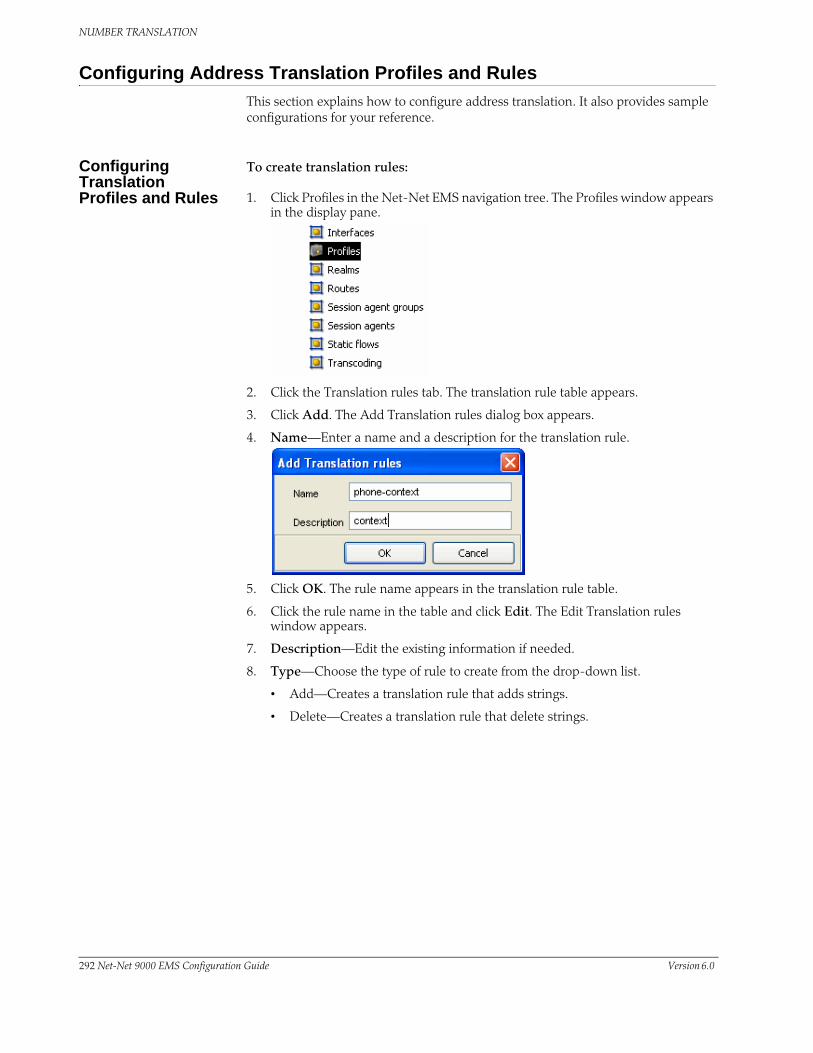
NUMBER TRANSLATION
Configuring Address Translation Profiles and RulesThis section explains how to configure address translation. It also provides sample configurations for your reference.
Configuring Translation Profiles and Rules
To create translation rules:
1. Click Profiles in the Net-Net EMS navigation tree. The Profiles window appears in the display pane.
2. Click the Translation rules tab. The translation rule table appears.
3. Click Add. The Add Translation rules dialog box appears.
4. Name—Enter a name and a description for the translation rule.
5. Click OK. The rule name appears in the translation rule table.
6. Click the rule name in the table and click Edit. The Edit Translation rules window appears.
7. Description—Edit the existing information if needed.
8. Type—Choose the type of rule to create from the drop-down list.
• Add—Creates a translation rule that adds strings.
• Delete—Creates a translation rule that delete strings.
292 Net-Net 9000 EMS Configuration Guide Version 6.0

NUMBER TRANSLATION
• Replace—Creates a translation rule that replace one string with another.
The rule type you choose determines which of the remaining fields are activated.
Adding a String To create a rule that adds a string:
1. String—Enter the string you want the rule to add.
2. Index—Enter the position where you want to add the string. Zero (0) is the left most position. If you want to add a string at the end of an number, enter a dollar-sign “$”.
Deleting a String To create a rule that deletes a string:
1. String—Enter the text you want to delete in the String field.
2. Index—If you are deleting a portion of the address string, enter the index number in the Index text box. Remember to enter the number of characters you are deleting in the form of at-signs “@” in the delete string field.
The first matched string will be deleted, any remaining strings that match will remain. For example, if the address is 187521865 and the string to delete is “18,”
Version 6.0 Acme Packet, Inc. Technical Publications 293

NUMBER TRANSLATION
only the first instance of “18” will be deleted. The second instance will remain after translation.
Replacing a String To create a translation rule that replaces a string:
1. Add String—Enter the new string you want to use in the Add section textboxes.
2. Delete String—Enter the existing string you want to replace in the Delete section textboxes.
3. Click Apply.
Translation Profiles To create a translation profile:
1. Click Profiles in the Net-Net EMS navigation tree. The Profiles window appears in the display pane..
294 Net-Net 9000 EMS Configuration Guide Version 6.0

NUMBER TRANSLATION
2. Click the Translation profile tab. The translation profile table appears.
3. Click Add. The Add Translation profile window appears.
4. Name—Enter a name and description for the translation profile and click OK. The new profile appears in the translation profile table.
5. Click the translation profile in the table and click Edit. The Edit Translation profile window appears.
6. Click Add in the From translation rules portion of the Edit Translation profile screen.
The Translation rule select window appears.
7. Name—Select the first translation rule to apply to the From / rules calling list from the drop-down list.
8. Click OK to continue.
9. Repeat this process until you have added all the Translation Rules to the From translation rules for this Translation profile. Multiple rules can be entered in this field. The order you enter them in is the order in which they are applied.
10. For “To” Translation rules, repeat steps 7, 8, and 9 from the section of the Translation profile screen to create the translation profile applied to outgoing
Version 6.0 Acme Packet, Inc. Technical Publications 295

NUMBER TRANSLATION
traffic. Multiple rules can be entered in this field. The order you enter them in is the order in which they are applied.
11. Click Apply at the bottom of the Translation profile window to complete creating translation profiles.
Applying Profiles to a Session Agent
To configure address translation for a session agent:
1. Click Session Agents. The Session agents window appears.
2. Click on a configured session agent in the session agent table, and click Edit.
3. Click the SIP session agent routing & address translation tab. Scroll to Address translation profiles.
4. Inbound—Select a translation profile for Inbound sessions from the drop-down list, affecting incoming traffic.
5. Outbound—Select a translation profile for Outbound sessions from the drop-donw list, affecting outgoing traffic.
The drop-down lists contain all configured translation profiles. You can only select one profile for each type category.
6. Click Apply at the bottom of the SIP session agent window to complete applying the translation profile.
296 Net-Net 9000 EMS Configuration Guide Version 6.0

NUMBER TRANSLATION
Applying Translation Profiles to a Realm
To configure address translation for a realm:
1. Click Realms in the Net-Net EMS navigation tree. The Realm window appears in the display pane.
2. From the Realm window, click on a configured realm, and click Edit. The Edit realm window appears.
3. Inbound—Select a translation profile for Inbound sessions from the drop-down list, affecting incoming traffic.
4. Outbound—Select a translation profile for Outbound sessions from the drop-donw list, affecting outgoing traffic.
The drop-down lists contain all configured translation profiles. You can only select one profile for each type category.
5. Click Apply.
Other Translations
SIP NAT Translations There are other translations that occur by way of SIP NAT functionality acting on the SIP R-URI, From-URI, and To URI headers. The translation of URIs in the SIP message occurs as messages are received and sent from the Net-Net SBC’s SIP proxy. These translations create a bridge between the external and home realms and remove all references to the original IP addressing from the packets sent to the destination network.
The purpose of this translation is to prevent private IP addresses from appearing in SIP message URIs while traveling through the public network. This aspect of the SIP NAT’s functionality involves either translating the private address to a public address or encrypting the private address into the URI.
For information about configuring these additional number mappings, see the SIP Signaling Service chapter of this guide.
FQDN Mapping The Net-Net SBC maps FQDNs that appear in certain headers of incoming SIP messages to the IP address that the Net-Net SBC inserts in outgoing SIP contact
Version 6.0 Acme Packet, Inc. Technical Publications 297

NUMBER TRANSLATION
headers. The mapped FQDNs are restored in the SIP headers in messages that are sent back to the originator.
This feature is useful to carriers that use IP addresses in the SIP From address to create trunk groups in a PSX for routing purposes. When the carrier’s peer uses FQDNs, the carrier is forced to create trunk groups for each possible FQDN that it might receive from a given peer. Similarly, this can apply to SIP Contact and P-asserted-identity headers.
For information about configuring these additional number mappings, see the SIP Signaling Service chapter of this guide.
298 Net-Net 9000 EMS Configuration Guide Version 6.0

11 Admission Control and Quality ofService Reporting
OverviewThis chapter describes how to configure the Net-Net SBC for call admission control and Quality of Service (QoS) monitoring. Call admission control lets you manage call traffic based on several different policies. It is aimed at managing call admission rates in the network, enabling you to maintain suitable QoS levels. A new call is admitted only if it meets the requirements
QoS reporting provides you with real-time evaluation of network and route performance. It lets you contrast internal domain and external domain performance and facilitates SLA verification and traffic engineering.
About Call Admission ControlThe Net-Net SBC provides call admission control capabilities based on the following policies:
• Bandwidth (single and multi-level policies)
• Session capacity
• Session rate (sustained and burst)
Note: In order to provide admission control for networks to which the Net-Net SBC is not directly connected, you need to define multiple realms per network interface.
Bandwidth-Based Admission Control
The Net-Net SBC is a policy enforcement point for bandwidth-based call admission control. Sessions are admitted or rejected based on bandwidth policies, configured on the Net-Net SBC for each realm.
To manage bandwidth consumption of a network’s overall capacity, you can configure aggregate bandwidth policies for each realm. See Configuring Realms for additional information.
As the Net-Net SBC processes call requests to and from a particular realm, the bandwidth consumed for the call is decremented from the bandwidth pool for that realm. The Net-Net SBC determines the required bandwidth from the SDP/H.245 information for SIP. Any request that would cause the bandwidth constraint to be exceeded is rejected with a SIP 503 Service Unavailable.
For example, if an incoming SIP message requests PCMU for a payload/encoding name, a zero (0) payload type, and an 8000 cycle clock rate, the Net-Net SBC must determine how much bandwidth is needed.
Version 6.0 Acme Packet, Inc. Technical Publications 299

ADMISSION CONTROL AND QUALITY OF SERVICE REPORTING
To accomplish this task, the system checks the media profile values and reserves the bandwidth required for flows. If the required bandwidth for the new flow exceeds the available bandwidth at the time of the request, the Net-Net SBC rejects the session.
With these mechanisms, the Net-Net SBC provides bandwidth-based admission control.
Multi-Level Bandwidth Policy Nesting
Multi-level nesting of bandwidth policy enforcement addresses the following issues:
• Bandwidth over-subscription: access or transit transport networks are aggregated and/or oversubscribed. For example, digital subscriber lines (DSL), Frame Relay (FR), and Asynchronous Transfer Mode (ATM). Admission control policies must reflect access network topology.
• Bandwidth partitioning for multiple services: access or transit bandwidth is partitioned among multiple service profiles (for example, SIP and MGCP) in the same customer network.
• Multi-site VPN environments: admission control must be applied at the site level as well as the VPN level.
The following example illustrates different scenarios; in each there are two or more levels of admission control required. Nested admission control is best depicted by the DSL broadband example.
In DSL access networks, ATM network bandwidth is typically oversubscribed at rates up to 400/1. At Level 3 (above), hundreds of users virtual circuits (VCs) are aggregated to a smaller set of virtual paths (VPs) at each DSLAM. At Level 2, many
Parent Realm ABCD
Signaling Service (SIP, H.323, MGCP) Max BW Steering Pool
Sub-realm AB
Media/BW only Max BW Steering pool
Sub-realm CD
Media/BW only Max BW Steering pool
Sub-realm AMedia/BW
onlyMax BW
addr-prefixSteering
pool
Sub-realm DMedia/BW
onlyMax BW
Addr-prefixSteering
pool
Sub-realm CMedia/BW
onlyMax BW
Addr-prefixSteering
pool
Sub-realm BMedia/BW
onlyMax BW
Addr-prefixSteering
pool
Signaling Interface
REALM GROUP
DSLAMA
DSLAMD
DSLAMC
DSLAMB
ACCESS NETWORKATMSW
ATMSW
ATMSW
BRAS
Level 3Realms A-D100's VCs
(realms AB & CD)
Level 2Realms AB & CD
Aggregate traffic at ATM SW
Realm ABCD
Level 1Realm ABCDAll traffic from
access network
NET-NET SD
VLAN 0
PHY 0
300 Net-Net 9000 EMS Configuration Guide Version 6.0

ADMISSION CONTROL AND QUALITY OF SERVICE REPORTING
virtual paths are aggregated at the first ATM switch. Finally, at Level 1, all traffic from all subscribers in the access network is aggregated at the BRAS. Each level of aggregation is oversubscribed, creating the need to perform admission control at each level.
From a Net-Net SBC perspective, multiple tiers of realms are supported, each with its unique bandwidth policy. Only the lowest order realm (Level 3) requires an address prefix (that assigned to the DSLAM) that must be used by the Net-Net SBC to determine in which realm a user resides. When a call request to or from a particular user is received, the Net-Net SBC checks each realm in the path to determine whether sufficient bandwidth is available to place the call.
Session Capacity- and Rate-based Admission Control
A session agent defines a signaling endpoint. It is a next hop signaling entity that can be configured to apply traffic shaping attributes. You can define concurrent session capacity and rate attributes for each session agent.
You can configure a set of attributes and constraints for each session agent to support session access control. In this configuration, the Net-Net SBC only accepts requests from configured session agents. And you can set up session admission control so that the Net-Net SBC limits the number of concurrent inbound and outbound sessions for any known service element.
The Net-Net SBC denies a call request to any destination that has exceeded its configured policies for session capacity and session rate. The Net-Net EMS might reject the call request back to the originator. If multiple destinations are available, the Net-Net SBC will check current capacity and rate for each destination and attempt to route the call only to destinations whose policy limits have not been reached.
Configuring Admission ControlThis section explains how to session agents for admission control.
Configuration Timestamp
You might see the following information on some of the configuration windows:
This is a configuration timestamp that displays last modified information for configuration changes made using Net-Net EMS.
When you make configuration changes to elements, the Last modified by field displays the following information:
• Net-Net EMS identifier
• Name of the user that made the modification
• IP address of the host machine upon which Net-Net EMS is running
• Relevant time zone information to specify how to interpret the timestamp in the Last modified date field.
For example:
EMS_admin_172.30.80.2_UTC
Version 6.0 Acme Packet, Inc. Technical Publications 301

ADMISSION CONTROL AND QUALITY OF SERVICE REPORTING
The Last modified date is displayed in the string date/time format, YYYY-MM-DD HH:MM:SS. For example 2007-11-07 15:16:05. When you make configuration changes using the Net-Net EMS, the date timestamp is specified in UTC.
If a sub-element is modified the timestamp belonging to the element is updated to indicate the modification time.
Adding a Session Agent
This section describes how to add, configure, and delete admission control for your Net-Net SBC using the Net-Net EMS.
1. Click Session agents in the Net-Net EMS navigation tree.
The Session agent window appears in the Net-Net EMS display pane. The window displays a table containing all configured session agents saved on the Net-Net SBC.
2. Click Add. The Add Session agent box appears.
3. Name(FQDN)—Enter the name you want to use for this session agent in FQDN format.
4. Protocol—Select the protocol from the drop-down list to be used for this session agent.
5. Click OK. The session agent appears in the table in the session agent window.
302 Net-Net 9000 EMS Configuration Guide Version 6.0

ADMISSION CONTROL AND QUALITY OF SERVICE REPORTING
Configuring a Session Agent
1. Click Session agents in the Net-Net EMS navigation tree.
The Session agent window appears in the Net-Net EMS display pane. The window displays a table containing all configured session agents saved on the Net-Net SBC. Configuration for each type of session agent is identical.
2. Select the session agent you want to configure.
3. Click Edit at the bottom of the window. The Edit Session agent window appears.
4. Select the SIP session agent constraints tab.
Configuring Session Constraints
1. Session constraints—Click the checkbox.
2. Max. inbound and outbound sessions (#)—Enter the maximum number of inbound and outbound sessions.
3. Max. outbound sessions (#)—Enter the maximum number of outbound sessions.
4. Max. INVITE burst rate (# sessions per sec)—Enter the maximum SIP INVITE burst rate in sessions per second; this is the maximum number session initiation messages this session agent can send or receive per second within the burst rate window.
5. Max. INVITE sustained rate (# sessions per sec)—Enter a new burst rate window in seconds; this value is the period of time over which the burst rate is computed.
6. Burst rate window (sec)—Enter a number to set the burst window period (in seconds) that is used to measure the sustained rate.
7. Sustained rate window (sec)—Enter a new sustained rate window in seconds; this is the time frame used to measure the sustained bandwidth rate.
Version 6.0 Acme Packet, Inc. Technical Publications 303

ADMISSION CONTROL AND QUALITY OF SERVICE REPORTING
Configuring Timers
1. After threshold reached before resuming INVITES to SA—Enter the time in seconds after which the SIP proxy should resume sending session invitations to the session agent.
2. After SA unresponsive before resuming INVITES to SA—Enter the time in seconds the SIP proxy must wait between the time an invitation is sent to an SA and the time it tries again.
3. After communication established before SA considered ‘in service’—Enter the time in seconds the session agent must be operational before it is considered in-service.
4. Click OK.
Deleting a Session Agent
To delete an existing session agent:
1. Click Session agents in the Net-Net EMS navigation tree.
The Session agent window appears in the Net-Net EMS display pane. The window displays a table containing all configured session agents saved on the Net-Net SBC.
2. Select a row in the table you want to delete.
304 Net-Net 9000 EMS Configuration Guide Version 6.0
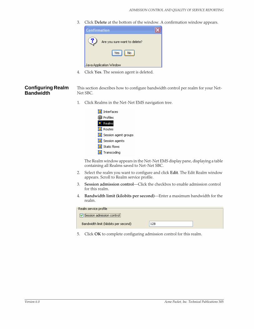
ADMISSION CONTROL AND QUALITY OF SERVICE REPORTING
3. Click Delete at the bottom of the window. A confirmation window appears.
4. Click Yes. The session agent is deleted.
Configuring Realm Bandwidth
This section describes how to configure bandwidth control per realm for your Net-Net SBC.
1. Click Realms in the Net-Net EMS navigation tree.
The Realm window appears in the Net-Net EMS display pane, displaying a table containing all Realms saved to Net-Net SBC.
2. Select the realm you want to configure and click Edit. The Edit Realm window appears. Scroll to Realm service profile.
3. Session admission control—Click the checkbox to enable admission control for this realm.
4. Bandwidth limit (kilobits per second)—Enter a maximum bandwidth for the realm.
5. Click OK to complete configuring admission control for this realm.
Version 6.0 Acme Packet, Inc. Technical Publications 305

ADMISSION CONTROL AND QUALITY OF SERVICE REPORTING
SIP Admission Control
This section describes how to configure admission control based on an endpoint’s registration state.
1. Click Realms in the Net-Net EMS navigation tree.
The Realm window appears in the Net-Net EMS display pane, displaying a table containing all Realms saved to Net-Net SBC.
2. Select the realm where you want to configure admission control.
3. Click Edit. The Edit Realm window appears.
4. Select the Services/Protocols tab.
5. Select the Service/Protocol name you want to configure and click Edit. The Edit SIP service window appears.
6. Select a SIP signaling interface you want to configure admission control and click Edit. The Edit SIP signaling interface window appears.
7. Scroll to Allowed connections.
8. Anonymous mode—Choose the criteria for admission control that you want applied when SIP requests are processed.
The following table lists the available options:
Option Description
all No ACL is applied and the all anonymous connections are allowed.
agents-only Only requests from configured session agents are processed. The Net-Net SBC responds to all other requests with a forbidden response.
realm-prefix Only requests from session agents and addresses matching the realm’s address prefix are processed. All other requests are rejected with a 403 (Forbidden) response.
registered Only requests from session agents and registered endpoints are processed. REGISTER allowed from any endpoint.
registered-prefix Only requests from session agent and registered endpoint addresses that match the realm’s realm prefix are processed.
306 Net-Net 9000 EMS Configuration Guide Version 6.0

ADMISSION CONTROL AND QUALITY OF SERVICE REPORTING
9. Click Apply. You will be returned to the SIP service window.
10. Click Apply. You will be returned to the Edit realm window.
11. Click Apply.
Aggregate Session Constraints for SIPYou can configure a full suite of session constraints and apply them to a SIP interface.
Session constraints configured natively on a SIP interface take precedence over session constraints applied in aggregate to a SIP interface.
Using the constraints you have set up, the Net-Net SBC checks and limits traffic according to those settings for the SIP interface. If you do not set up the session constraints or you do not apply them in the SIP interface, then that SIP interface will be unconstrained.
SIP interfaces have two states: “In Service” and “Constraints Exceeded.” When any one of the constraints is exceeded, the status of the SIP interface changes to “Constraiends”. The session constraint timers that apply to the SIP interface are: After threshold reached before resuming INVITES, Burst window (sec), and Sustained window.
Version 6.0 Acme Packet, Inc. Technical Publications 307

ADMISSION CONTROL AND QUALITY OF SERVICE REPORTING
Configuring Session Constraints
To configure the session constraints:
1. Click Profiles in the Net-Net EMS navigation tree.
The Profiles window appears in the Net-Net EMS display pane.
2. Click the Session constraints tab.
3. Click Add. The Add Session constraints window appears.
4. Session constraints name—Enter the name for this session constraints configuration; this is a unique identifier that you will use in the SIP interface when you want the session constraints applied there.
5. Enable—Leave the checkbox checked (default) to use these session constraints. To disable the session constraints, click the checkbox to uncheck it.
6. Max. Number of sessions (#)—Enter the maximum sessions allowed for this constraint. The minimum value is 0 (default), and the maximum is 999999999.
7. Max. outbound sessions (#)—Enter the maximum outbound sessions allowed for this constraint. The minimum value is 0 (default), and the maximum is 999999999.
8. Max. inbound sessions (#)—Enter the maximum inbound sessions allowed for this constraint. The minimum value is 0 (default), and the maximum is 999999999.
9. Max. burst rate (# sessions per sec)—Enter the maximum burst rate (invites per second) allowed for this constraint. This value should be the sum of the max. inbound burst rate and the max. outbound burst rate. The minimum value is 0 (default) and the maximum value is 999999999.
10. Max. sustained rate (# sessions per sec)—Enter the maximum rate of session invitations per second allowed within the current window for this constraint. The minimum value is 0 (default), and the maximum is 999999999.
For the sustained rate, the Net-Net SBC maintains a current and previous window size. The period of time over which the rate is calculated is always between one and two window sizes.
11. Max. inbound burst rate (# sessions per sec)—Enter the maximum inbound burst rate (number of session invitations per second) for this constraint. The
308 Net-Net 9000 EMS Configuration Guide Version 6.0

ADMISSION CONTROL AND QUALITY OF SERVICE REPORTING
minimum value for this parameter is 0 (default), and the maximum is 999999999.
12. Max. inbound sustained rate (# sessions per sec)—Enter the maximum inbound sustain rate (of session invitations allowed within the current window) for this constraint. The minimum value for this parameter is 0 (default), and the maximum is 999999999.
For the sustained rate, the Net-Net SBC maintains a current and previous window size. The period of time over which the rate is calculated is always between one and two window sizes.
13. Max. outbound burst rate (# sessions per sec)—Enter the maximum outbound burst rate (number of session invitations per second) for this constraint. The minimum value for this parameter is 0 (default), and the maximum is 999999999.
14. Max. outbound sustained rate (# sessions per sec)—Enter the maximum outbound sustain rate (of session invitations allowed within the current window) for this constraint. The minimum value for this parameter is 0 (default), and the maximum is 999999999.
15. After threshold reached before resuming INVITES—Enter the number of seconds that is used to place an element (like a session agent) in the standby state when it has been take out of service because of excessive transaction timeouts. The minimum value for this parameter is 0 (default), and the maximum is 999999999.
16. After being unresponsive before resuming INVITES—Enter the time delay in seconds the SIP proxy must wait from the time that it sends an invitation to a session-agent and gets no response before it tries again to elicit a response from a previuosly unresponsive session agent. The minimum value for this parameter is 0 (default) and the maximum is 999999.
17. After communication established before being considered ‘in service’—Enter the time in seconds the session-agent must be operational (once communication is re-established) before the session agent is declared to be in-service. This value gives the session agent adequate time to initialize. The minimum value for this parameter is 0 (default) and the maximum is 999999.
18. Burst window (sec)—Enter the time in seconds that you want to use to measure the burst rate; the “window” is the time over which the burst rate is calculated, and is used for the over all burst rate as well as the inbound and outbound burst rates. The minimum value for this parameter is 0 (default), and the maximum is 999999999.
Version 6.0 Acme Packet, Inc. Technical Publications 309

ADMISSION CONTROL AND QUALITY OF SERVICE REPORTING
19. Sustained window—Enter the time in seconds used to measure the sustained rate; the “window” is the time over which the sustained rate is calculated, and is used for the over all sustained rate as well as the inbound and outbound sustained rates. The minimum value for this parameter is 0 (default), and the maximum is 999999999.
20. Minimum number of seizures—Enter the minimum number of seizures for a no-answer scenario. The default is 5 and the valid range is 0-999999.
21. Minimum answer to seizure ratio percentage—Enter the minimum answer to seizure ration in percentage format. The minimum value for this parameter is 0 (default), and the maximum is 999999.
22. Click OK.
Applying Session Constraints to SIP Interfaces
To apply session constraints to a SIP interface:
1. Click Realms in the Net-Net EMS navigation tree.
The Realm window appears in the display pane.
2. Click a realm in the Realm table to choose it and click Edit. The Edit realm window appears.
3. Click the Services/Protocols tab.
4. Click a SIP interface name to choose it and click Edit. The Edit SIP service window appears.
5. Click the SIP interface tab.
6. Scroll to Session constraints.
7. Session constraints—Choose the name of the session constraints configuration that you want to apply to this SIP interface from the drop-down list.
8. Click Apply.
310 Net-Net 9000 EMS Configuration Guide Version 6.0

ADMISSION CONTROL AND QUALITY OF SERVICE REPORTING
SIP Per-User CACThe Net-Net SBC’s call admission control (CAC) is enhanced to support a greater degree of granularity for SIP sessions. You configure the realm to define CAC by mode, bandwidth, and sessions.
If you do not enable this feature, the Net-Net SBC performs call admission control (CAC) based on:
• Bandwidth limits configured in realms and nested realms
• Number of media flows available through the steering pool per realm
• Number of inbound sessions configured for a SIP session agent
• Number of total sessions (inbound and outbound) per SIP session agent
• Use of the Net-Net SBC’s support for common open policy service (COPS), allowing the Net-Net SBC to perform CAC based on the policies hosted in an external policy server
With these methods, you can configure a basic level of call admission control in order to ensure that a session agent’s capacity is not exceeded. You can also ensure that signaling and media bandwidth capacities are not exceeded for physical trunks and peers.
When you enable the SIP per-user CAC feature, the Net-Net SBC only allows the configured number of calls or total bandwidth to and from each user in a particular realm.
How It Works You should note that the functionality this section describes only works if you enable registration caching on your Net-Net SBC.
For SIP sessions, the Net-Net SBC keeps track of the amount of bandwidth a user consumes and the number of active sessions per address of record (AoR) or per IP address, depending on the CAC mode you select (either aor or ip). When an endpoint registers with the Net-Net SBC, the Net-Net SBC allots it a total amount of bandwidth and total number of sessions.
Per User CAC Modes There are three modes that you can set for this feature, and each has an impact on how the other two per-user-CAC parameters are implemented:
• none—No per user CAC is performed for users in the realm
• aor—The Net-Net SBC performs per user CAC according to the AoR and the contact associated with that AoR for users in the realm
• ip—The Net-Net SBC performs per user CAC according to the IP address and all endpoints that are sending REGISTER messages from the IP address for users in the realm
Per User CAC Sessions
You can set the number of CAC for sessions per user in the realm configuration. Depending on the CAC mode you set, the sessions are shared between contacts for the same AoR or the endpoints behind the same IP address.
When it receives an INVITE, the Net-Net SBC determines the registration entry for the calling endpoint and the registration for the called endpoint. It then decides if a session can be established between the two. If it can, the Net-Net SBC establishes
Version 6.0 Acme Packet, Inc. Technical Publications 311

ADMISSION CONTROL AND QUALITY OF SERVICE REPORTING
the session and changes the active session count for the calling and called endpoints. The count is returned to its original value once the session is terminated.
Per User CAC Bandwidth
You can set the per user CAC bandwidth in realm configuration, too, and it is handled much the same way that the sessions are handled. Depending on the CAC mode you set, the bandwidth is shared between contacts for the AoR or the endpoints behind the same IP address. All endpoints must be registered with the Net-Net SBC.
When it receives a Request with SDP, the Net-Net SBC checks to see if there is enough bandwidth for the calling endpoint and for the called endpoint. The Net-Net SBC assumes that the bandwidth usage is symmetric, and it uses the maximum bandwidth configured for the codec that it finds in the Request. In the event that there are multiple streams, the Net-Net SBC determines the total bandwidth required for all of the streams. If the required bandwidth exceeds what is available for either endpoint, the Net-Net SBC rejects the call (with a 503 error response). If the amount of available bandwidth is sufficient, then the used bandwidth value is increased for both the registered endpoints: calling and called. Any mid-session requests for changes in bandwidth, such as those caused by modifications in codec use, are handled the same way.
The Net-Net SBC also keeps track of the bandwidth usage on a global level. When the call terminates, the bandwidth it was consuming is returned to the pool of available bandwidth.
Notes on HA Nodes This feature has been implemented so that a newly active system is able to perform SIP per user CAC. The standby Net-Net SBC is updated with the appropriate parameters as part of the SIP session update.
Configuring SIP Per-User CAC
To configure SIP per-user CAC:
1. Click Realms in the Net-Net EMS navigation tree.
The Realm window appears in the display pane.
2. Click the realm you want to configure in the Realm table and click Edit. The Edit Realm window appears.
3. Click in the Realm tab.
4. Scroll to the Call Admission Control (CAC) section.
5. Endpoint identifier—Select either aor or ip from the drop-down list. If you do not enter of either of these modes, the Net-Net SBC will not perform per-user CAC.
312 Net-Net 9000 EMS Configuration Guide Version 6.0

ADMISSION CONTROL AND QUALITY OF SERVICE REPORTING
6. Bandwidth constraints—Click the Bandwidth constraints checkbox to enable bandwidth constraints.
7. Maximum bandwidth allowed—If Bandwidth constraints is enabled, enter the maximum bandwidth per user for dynamic flows to and from the user.
Leaving this parameter set to 0 (default) means that there is unlimited bandwidth, and the per user CAC feature is disabled in terms of the constraint on bandwidth. The value range is a minimum of 0, and a maximum of 4294967295.
8. Session constraints—Click the Sessions constraints checkbox to enable session constraints.
9. Maximum sessions allowed—Enter the maximum number of sessions per user for dynamic flows to and from the user. Leaving this parameter set to 0 (default) means that there are unlimited sessions, which means the per user CAC feature is disabled in terms of the constraint on sessions. The value range is a minimum of 0, and a maximum of 4294967295.
10. Click Apply.
Monthly Minutes-based Call Admission ControlYou can configure call admission control based on the number of minutes a month per realm to use for SIP and H.323 sessions. You configure CAC in minutes but the Net-Net SBC performs CAC to the second. When used with nested realms, the parent realm will have the total minutes for all its child realms (i.e., at least the sum of minutes configured for the child realms).
The Net-Net SBC calculates the number of minutes used when a call completes, and counts both call legs for a call that uses the same realm for ingress and egress. The total time attributed to a call is the amount of time between connection (SIP 200 OK or H.323 Connect) and disconnect (SIP BYE or H.323 Release Complete), regardless of whether media is released or not; there is no pause for calls being placed on hold.
If the number of minutes is exhausted, the Net-Net SBC rejects calls with a SIP 503 Service Unavailable message (including additional information “monthly minutes exceeded”) or an H.323 Release Complete message. In the event that the limit is reached mid-call, the Net-Net SBC continues with the call that pushed the realm over its threshold, but does not accept new calls. When the limit is exceeded, the Net-Net SBC issues an alarm and sends out a trap including the name of the realm; a trap is also sent when the alarm condition clears.
Note: The Net-Net SBC does not reject GETS/NSEP calls based on monthly minutes CAC.
Version 6.0 Acme Packet, Inc. Technical Publications 313

ADMISSION CONTROL AND QUALITY OF SERVICE REPORTING
You can change the value for minutes-based CAC in a realm at any time, though revising the value downward might cause limits to be reached. This value resets to zero (0) at the beginning of every month, and is checkpointed across both systems in an HA node. Because this data changes so rapidly, the value will not persist across an HA node if both systems undergo simultaneous failure or reboot.
Caveats This feature is not supported for HA nodes running H.323.
Configuring monthly minutes-based CAC
This section shows you how to configure minutes-based CAC for realms. Setting the monthly minutes parameters to zero (0) disables this feature.
314 Net-Net 9000 EMS Configuration Guide Version 6.0

ADMISSION CONTROL AND QUALITY OF SERVICE REPORTING
To configure minutes-based CAC:
1. Click Realms in the Net-Net EMS navigation tree.
The Realm window appears in the display pane.
2. Choose a SIP interface and click Edit. The Edit Realm window appears.
3. Click the Realm tab and scroll to Monthly minutes allowed (minutes).
4. Monthly minutes allowed (minutes)—Enter the number of minutes allowed during a calendar month in this realm for SIP and H.323.calls. Range of values is 0-71582788.
5. Click Apply.
About QoS ReportingThis section describes the Net-Net SBC QoS reporting. QoS reporting provides you with real-time evaluation of network and route performance. It lets you contrast internal domain and external domain performance and facilitates SLA verification and traffic engineering. Net-Net SBC QoS reporting is a measurement tool that collects statistics on Voice over IP (VoIP) call flows for SIP. To provide information, the Net-Net SBC writes additional parameters to the Remote Authentication Dial-in User Service (RADIUS) call record.
You can use QoS statistics for SLA customer reporting, fault isolation, SLA verification, and traffic analysis. The Net-Net SBC employs specialized hardware to inspect Real-Time Transport Protocol (RTP) and Real-Time Transport Control Protocol (RTCP) flows while maintaining wire-speed packet forwarding. QoS metrics are collected and reported on a per-session and per call-leg basis. These metrics are reported through real-time RADIUS records along with call accounting data.
Overview When a conversation is established between two endpoints, two flows are present in each direction:
• RTP flow carries traffic between endpoints with a predictable packet arrival rate. The packets headers have sequence numbers that are used to determine whether packets are missing or lost.
• RTCP flow carries information about the RTP flow and keeps a different record. The RTCP packets contain timestamps based on Network Time Protocol (NTP).
Version 6.0 Acme Packet, Inc. Technical Publications 315

ADMISSION CONTROL AND QUALITY OF SERVICE REPORTING
QoS Statistics Reported QoS data includes the following per-flow statistics:
• RTP and RTCP lost packets—Count of lost packets for both RTP and RTCP based on comparing the sequence numbers since the beginning of the call or the last context memory poll.
• RTP and RTCP average jitter—Incremental number of packets for both RTP and RTCP that have been used to generate the total and max jitter since the beginning of the call or the last context memory poll. The incremental accumulated jitter (in milliseconds) over all the packets received.
• RTP and RTCP maximum jitter—Maximum single jitter value (in milliseconds) for both RTP and RTCP from all the packets since the beginning of the call or the last context memory poll.
• RTCP average latency—Number of RTCP frames over which latency statistics have been accumulated and the incremental total of latency values reported since the beginning of the call or the last context memory poll.
• RTCP maximum latency—Highest latency value measured since the beginning of the call or the last context memory poll.
• RTP packet count
• RTP bytes sent and received
• RTCP lost packets—RTP lost packets reported in RTCP packets.
• ATP lost packets—Lost packets determined by monitoring RTP sequence numbers.
RADIUS Support All the QoS statistics go into the RADIUS CDR. If a RADIUS client is configured on the Net-Net SBC, any time a call occurs a record is generated and sent. Only Stop RADIUS records contain the QoS statistic information.
For additional details about RADIUS support, see the Net-Net SBC support for RADIUS, including a dictionary of the standard RADIUS attributes supported by the Net-Net SBC and the Acme Packet accounting VSAs, see the RADIUS Reference Guide.
Configuring QoSThis section explains how to configure QoS. To generate QoS metrics, you need to enable QoS for the realm of the originating caller. The ingress realm determines whether QoS is turned on for a specific flow.
Note: If you run with QoS turned on one side only and disabled on the other you lose the ability to measure latency through the use of RTCP timestamps.
Configuration Timestamp
You might see the following information on some of the configuration windows:
This is a configuration timestamp that displays last modified information for configuration changes made using Net-Net EMS.
316 Net-Net 9000 EMS Configuration Guide Version 6.0

ADMISSION CONTROL AND QUALITY OF SERVICE REPORTING
When you make configuration changes to elements, the Last modified by field displays the following information:
• Net-Net EMS identifier
• Name of the user that made the modification
• IP address of the host machine upon which Net-Net EMS is running
• Relevant time zone information to specify how to interpret the timestamp in the Last modified date field.
For example:
EMS_admin_172.30.80.2_UTC
The Last modified date is displayed in the string date/time format, YYYY-MM-DD HH:MM:SS. For example 2007-11-07 15:16:05. When you make configuration changes using the Net-Net EMS, the date timestamp is specified in UTC.
If a sub-element is modified the timestamp belonging to the element is updated to indicate the modification time.
Configuring QoS This section describes how to enable QoS on your Net-Net SBC from the Net-Net EMS.
1. Click Realms in the Net-Net EMS navigation tree.
The Realm window appears in the display pane.
2. Select the realm you want to configure QoS for and click Edit. The Edit Realm window appears.
3. Scroll to QoS.
4. QoS measurements—Click the checkbox to enable QoS.
5. Profile name—Select a preconfigured QoS Profile name from the drop-down list.
6. Click Apply.
Version 6.0 Acme Packet, Inc. Technical Publications 317
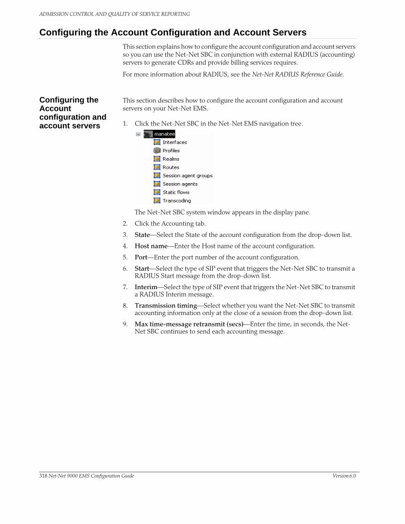
ADMISSION CONTROL AND QUALITY OF SERVICE REPORTING
Configuring the Account Configuration and Account ServersThis section explains how to configure the account configuration and account servers so you can use the Net-Net SBC in conjunction with external RADIUS (accounting) servers to generate CDRs and provide billing services requires.
For more information about RADIUS, see the Net-Net RADIUS Reference Guide.
Configuring the Account configuration and account servers
This section describes how to configure the account configuration and account servers on your Net-Net EMS.
1. Click the Net-Net SBC in the Net-Net EMS navigation tree.
The Net-Net SBC system window appears in the display pane.
2. Click the Accounting tab.
3. State—Select the State of the account configuration from the drop-down list.
4. Host name—Enter the Host name of the account configuration.
5. Port—Enter the port number of the account configuration.
6. Start—Select the type of SIP event that triggers the Net-Net SBC to transmit a RADIUS Start message from the drop-down list.
7. Interim—Select the type of SIP event that triggers the Net-Net SBC to transmit a RADIUS Interim message.
8. Transmission timing—Select whether you want the Net-Net SBC to transmit accounting information only at the close of a session from the drop-down list.
9. Max time-message retransmit (secs)—Enter the time, in seconds, the Net-Net SBC continues to send each accounting message.
318 Net-Net 9000 EMS Configuration Guide Version 6.0

ADMISSION CONTROL AND QUALITY OF SERVICE REPORTING
10. Max. message queue before failover (#)—Enter the number of accounting messages to be held in the message waiting queue before a failover situation status is enacted.
11. Multiple server usage strategy—Select the strategy from the drop-down list you want used to select the accounting servers to which the Net-Net SBC will send its accounting messages.
Account Server This section describes how to configure accounting servers on your Net-Net EMS.
1. Click Add in the Accounting server section. The Add Accounting server window appears.
2. Host name or IP address—Enter the name or IP address of the host associated with the account server.
3. IP port—Retain the default 1813, or enter the number of the DUP port associated with the account server to which RADIUS messages are sent.
4. State—Select the state of the account server on the Net-Net SBC from the drop-down list. The default is enabled.
5. Min. round trip time threshold (ms)—Enter the minimum round trip time of an accounting message. The default is 250 milliseconds. If the fastest RTT is the strategy for the account configuration the value you enter here can be used to determine an order of preference (if all the configured account servers are responding in less than their minimum RTT).
6. VSA bundling—Select enabled from the drop-down list if you want the account server to bundle the VSAs within RADIUS accounting messages. Select
Version 6.0 Acme Packet, Inc. Technical Publications 319

ADMISSION CONTROL AND QUALITY OF SERVICE REPORTING
disabled if you do not. (Bundling means including multiple VSAs within the vendor value portion of the message.)
7. Max. time ACK (sec)—Enter the length of time in seconds that you want the Net-Net SBC with pending accounting messages to wait when it has not received a valid response from the target account server. The default is 60 seconds.
8. Min. time-reinstate delay (sec)—Enter the length of time in seconds that you want the Net-Net SBC to wait before resending messages to a disabled account server. The default is 30 seconds.
9. Shared secret—Enter the secret passed from the account server to the client. Transactions between the client and the the RADIUS server are authenticated by the shared secret.
10. NAS ID—Enter the NAS ID. The account server uses this value to identify the Net-Net SBC for the transmittal of accounting messages.
11. Click OK to finish configuring the accounting server.
320 Net-Net 9000 EMS Configuration Guide Version 6.0

12 Static Flows
IntroductionThis chapter describes the Net-Net SBC’s static flows feature. Static flows allow network traffic that matches specific criteria to pass through the Net-Net SBC unrestricted. This feature lets you steer traffic toward a particular destination based on its original characteristics. Static flows can range from being widely accessible to very restrictive, depending on the values you establish. Static flows are used for evaluation and testing purposes. They are also used for transporting a variety of signaling messages through the Net-Net SBC to achieve vendor interoperability.
About Static Flows The static flow element explicitly writes entries into the IP routing table. These entries are persistent and are not deleted as calls are set up and broken down. Refer to the following diagram to understand how a static flow works.
A static flow entry watches for traffic with specific criteria on a specified ingress realm; that traffic consists of the following criteria:
1. The IP packet enters the Net-Net SBC on the specified ingress realm.
2. The packet contains matching source address, subnet, and port criteria, field 1.
3. The packet contains matching destination address, subnet, and port criteria, field 2.
4. The packet contains a matching transport protocol, field 3.
If the above conditions are met, then the Net-Net SBC does the following:
1. The IP traffic is forwarded out of the Net-Net SBC on the specified egress realm.
2. The configured source address, subnet, and port criteria are written to the exiting packet, field 4.
3. The configured destination address, subnet, and port criteria are written to the exiting packet, field 5.
4. The original transport protocol and its contents remain unchanged as the packet exits into the egress realm.
SD
Ingress Realm
IP Packet
1. source-address/subnet:port2. destination-address/subnet:port3. transport protocol
Egress Realm
static flow
4. source-address/subnet:port5. destination-address/subnet:port6. transport protocol
IP Packet
Version 6.0 Acme Packet, Inc. Technical Publications 311

STATIC FLOWS
About Network Address Translation ALG
The Net-Net SBC supports Network Address and Port Translation (NAPT) and Trivial File Transfer Protocol (TFTP) functionality over media interfaces, collectively known as Network Address Translation (NAT) ALG. The NAT ALG feature is implemented as an extension of the static flow feature.
In some applications, the Net-Net SBC acts as an intermediary device, positioned between endpoints located in an access network and application servers located in a backbone network. The Net-Net SBC’s NAT ALG feature enables these endpoints to use non-VoIP protocols, such as TFTP and HTTP, to access servers in a provider’s backbone network to obtain configuration information.
NAT ALG parameters support RTC and can be dynamically reconfigured. The active NAT ALG configuration can be replicated on the standby SD in an HA configuration.
NAPT The NAPT ALG functionality is the same as that found in commercially available enterprise and residential NAT devices. The Net-Net SBC watches for packets entering a media interface that match source and destination IP address criteria. Matching packets are then redirected out of the egress interface, through a specified port range, toward a destination address.
TFTP The TFTP ALG is implemented as an extension of the NAT ALG. It works slightly differently than traditional NAPT. In a TFTP session, the first packet is sent from a source endpoint to port 69 on the TFTP server. The TFTP server responds from another port. This port, from which the TFTP response originates, is used for the remainder of the TFTP session.
To act as a TFTP ALG, the Net-Net SBC will latch on the first return packet from the server to learn the server's port. The ingress-side destination port of the Net-Net
SDCLIENT SERVER
source
ingressinterface
egressinterface
destination
CLIENT SERVER
client sends toserver at port69
server respondswith a port of itsselection, whichis used for therest of thesession
312 Net-Net 9200 EMS Configuration Guide Version 6.0

STATIC FLOWS
SBC is changed to reflect the new communications port for the TFTP session. This process takes place without any user intervention.
Configuring Static FlowsThis section explains how to configure static flows. It also provides sample configurations for your reference. You can configure static flows with or without NAT ALG. If you configure static flows with NAT ALG, you can choose NAPT or TFTP as the ALG type.
Basic Static Flow Configuration Overview
This section outlines the basic static flow configuration, without NAT ALG. You configure static flows by specifying ingress traffic criteria followed by egress re-sourcing criteria.
When configuring static flows, the following conventions are used:
• An IP address of 0.0.0.0 matches all IP addresses.
• Not specifying a port implies all ports.
• Not specifying a subnet mask implies a /32, matching for all 32 bits of the IP address.
1. Set the static flows’ incoming traffic-matching criteria. First set the ingress realm where you expect to receive traffic that will be routed via a static flow. Second, set the traffic’s source IP address, source subnet, and source port or port range criteria. Third, set the traffic’s destination IP address, destination subnet, and destination port criteria. This is usually an external address on the Net-Net SBC.
2. Set the criteria that describes how traffic should be translated on the egress side of the Net-Net SBC. First set the egress realm where you want to send the traffic to be routed by this static flow. Second, set the traffic’s source IP address, source subnet, and source port or port range criteria. This is usually an external address on the Net-Net SBC. Third, set the traffic’s destination IP address, destination subnet, and destination port criteria.
3. Set the protocol this static flow entry acts upon. This type of packet, as the payload of the IP packet, remains untouched as traffic leaves the Net-Net SBC. Specifying a layer 4 protocol here acts as another criteria to filter against for this static flow.
The combination of entries in the ingress realm, ingress source address, ingress destination address, and protocol fields must be unique. For bidirectional traffic, you need to define a separate static flow in the opposite direction.
SDCLIENT SERVER
source
port to which theclient now sends
destination
destination port theserver now uses
Version 6.0 Acme Packet, Inc. Technical Publications 313

STATIC FLOWS
Configuration Timestamp
You might see the following information on some of the configuration windows:
This is a configuration timestamp that displays last modified information for configuration changes made using Net-Net EMS.
When you make configuration changes to elements, the Last modified by field displays the following information:
• Net-Net EMS identifier
• Name of the user that made the modification
• IP address of the host machine upon which Net-Net EMS is running
• Relevant time zone information to specify how to interpret the timestamp in the Last modified date field.
For example:
EMS_admin_172.30.80.2_UTC
The Last modified date is displayed in the string date/time format, YYYY-MM-DD HH:MM:SS. For example 2007-11-07 15:16:05. When you make configuration changes using the Net-Net EMS, the date timestamp is specified in UTC.
If a sub-element is modified the timestamp belonging to the element is updated to indicate the modification time.
Configuring Static Flows
This section describes how to configure static flows and NAPT/TFTP ALG on your Net-Net EMS.
1. Click Static flows in the Net-Net EMS navigation tree..
The Static flow window appears in the Net-Net EMS display pane. The window displays a table containing all configured static flows saved on the Net-Net SBC.
2. Click Add in the Static flow window. The Add static flow window appears.
3. In-realm—Select the incoming realm from the In realm drop-down list.
4. In source—Enter the IP address of the network that defines where the incoming traffic originates.
5. In destination—Enter the In destination IP address. Enter the ingress side’s destination. This is the IP address and port of the network interface in the ingress realm.
314 Net-Net 9200 EMS Configuration Guide Version 6.0

STATIC FLOWS
6. Protocol—Select the protocol this static flow applies to from the drop-down list.
7. Click Apply to continue. A confirmation window appears. Click the OK button to continue.
The new static flow appears in the Static flow window
Editing Static Flows 1. Select the static flow you want to configure and click Edit in the Static flow window. The Edit static flow window appears.
2. Realm—Select the egress realm ID from the Realm field in the To Realm section of the screen.
3. Source—Enter the egress realm’s source IP address, and bitmask and port if applicable.
4. Destination—Enter the egress realm’s destination IP address, and bitmask and port if applicable.
5. Click Apply to accept these values and continue.
Realms must be preconfigured in the realm object to appear in the drop-down lists for this selection.
Creating a NAPT or TFTP ALG Configuration
1. Select the static flow you want to configure and click Edit in the Static flow window. The Edit static flow window appears.
2. ALG type—Select either NAPT or TFTP from the drop-down list.
Version 6.0 Acme Packet, Inc. Technical Publications 315

STATIC FLOWS
3. Flow Policing—Click the checkbox to limit the bandwidth of this ALG service.
4. Maximum bandwidth allowed per flow—Enter the maximum bandwidth per flow for this ALG service.
5. Start port—Enter the starting port where the redirected flows are sourced from on the egress side.
6. End port—Enter the ending port where the redirected flows are sourced from on the egress side.
7. Flow time limit—Enter the total time in seconds for an ALG flow.
8. Initial guard timer—Enter the initial guard timer value in seconds for an ALG flow.
9. Subsequent guard timer—Enter the subsequent guard timer value in seconds for an ALG flow.
10. Click Apply to continue.
316 Net-Net 9200 EMS Configuration Guide Version 6.0

13 Security
IntroductionThis chapter explains Net-Net SBC security, which is designed to provide security for VoIP and other multimedia services. It includes access control, DoS attack, and overload protection, which help secure service and protect the network infrastructure (including the Net-Net SBC). In addition, Net-Net SBC security lets legitimate users still place calls during attack conditions; protecting the service itself.
Security Overview Net-Net SBC security includes the Net-SAFE framework’s numerous features and architecture designs. Net-SAFE is a requirements framework for the components required to provide protection for the Session Border Controller (SBC), the service provider’s infrastructure equipment (proxies, gateways, call agents, application servers, and so on), and the service itself.
The following diagrams illustrate Net-SAFE:
Each of Net-SAFE’s seven functions consists of a collection of more specific features:
• Session border controller DoS protection: autonomic, SBC self-protection against malicious and non-malicious DoS attacks and overloads at Layers 2 to 4 (TCP, SYN, ICMP, fragments, and so on) and Layers 5 to 7 (SIP signaling floods, malformed messages, and so on).
• Access control: session-aware access control for signaling and media using static and dynamic permit/deny access control lists (ACLs) at layer 3 and 5.
• Topology hiding and privacy: complete infrastructure topology hiding at all protocol layers for confidentiality and attack prevention security. Also, modification, removal or insertion of call signaling application headers and fields. Includes support for the SIP Privacy RFC.
Version 6.0 Acme Packet, Inc. Technical Publications 317

SECURITY
• VPN separation: support for Virtual Private Networks (VPNs) with full inter-VPN topology hiding and separation, ability to create separate signaling and media-only VPNs, and with optional intra-VPN media hair-pinning to monitor calls within a VPN.
• Service infrastructure DoS prevention: per-device signaling and media overload control, with deep packet inspection and call rate control to prevent DoS attacks from reaching service infrastructure such as SIP servers, softswitches, application servers, media servers or media gateways.
• Fraud prevention: session-based authentication, authorization, and contract enforcement for signaling and media; and service theft protection.
• Monitoring and reporting: audit trails, event logs, access violation logs and traps, management access command recording, Call Detail Records (CDRs) with media performance monitoring, raw packet capture ability and lawful intercept capability. The monitoring method itself is also secured, through the use of SSH and SFTP, and through the ability to use a separate physical Ethernet port for management access.
Denial of Service ProtectionThis section explains the Denial of Service (DoS) protection for the Net-Net SBC. The Net-Net SBC DoS protection functionality protects softswitches and gateways with overload protection, dynamic and static access control, and trusted device classification and separation at Layers 3-5. The Net-Net SBC itself is protected from signaling and media overload, but more importantly the feature allows legitimate, trusted devices to continue receiving service even during an attack. DoS protection prevents the Net-Net SBC host processor from being overwhelmed by a targeted DoS attack from the following:
• IP packets from an untrusted source as defined by provisioned or dynamic ACLs
• IP packets for unsupported or disabled protocols
• Nonconforming/malformed (garbage) packets to signaling ports
• Volume-based attack (flood) of valid or invalid call requests, signaling messages, and so on.
• Overload of valid or invalid call requests from legitimate, trusted sources
318 Net-Net 9200 EMS Configuration Guide Version 6.0

SECURITY
The following diagram illustrates DoS protection applied to the softswitch and to the Net-Net SBC.
Levels of DoS Protection
The multi-level Net-Net SBC DoS protection consists of the following strategies:
• Fast path filtering/access control: access control for signaling packets destined for the Net-Net SBC host processor as well as media (RTP) packets. The Net-Net SBC performs media filtering by using the existing dynamic pinhole firewall capabilities. Fast path filtering packets destined for the host processor require the configuration and management of a trusted list and a deny list for each Net-Net SBC realm (although the actual devices can be dynamically trusted or denied by the Net-Net EMS based on configuration). You do not have to provision every endpoint/device on the Net-Net SBC, but instead retain the default values.
• Host path protection: includes flow classification, host path policing and unique signaling flow policing. Fast path filtering alone cannot protect the Net-Net SBC host processor from being overwhelmed by a malicious attack from a trusted source. The host path and individual signaling flows must be policed to ensure that a volume-based attack will not overwhelm the Net-Net SBC’s normal call processing; and subsequently not overwhelm systems beyond it.
Version 6.0 Acme Packet, Inc. Technical Publications 319

SECURITY
The Net-Net SBC must classify each source based on its ability to pass certain criteria that is signaling- and application-dependent. At first each source is considered untrusted with the possibility of being promoted to fully trusted. The Net-Net SBC maintains two host paths, one for each class of traffic (trusted and untrusted), with different policing characteristics to ensure that fully trusted traffic always gets precedence.
• Host-based malicious source detection and isolation – dynamic deny list. Malicious sources can be automatically detected in real-time and denied in the fast path to block them from reaching the host processor.
About the Process DoS attacks are handled in the Net-Net SBC’s host path. The Net-Net SBC uses NAT table entries to filter out undesirable IP addresses; creating a deny list. After a packet from an endpoint is accepted through NAT filtering, policing is implemented in the Traffic Manager subsystem based on the sender’s IP address. NAT table entries distinguish signaling packets coming in from different sources for policing purposes. The maximum number of policed calls that the Net-Net SBC can support is 16K (on 32K CAM / IDT CAM).
The Traffic Manager has two pipes, trusted and untrusted, for the signaling path. Each signaling packet destined for the host CPU traverses one of these two pipes.
320 Net-Net 9200 EMS Configuration Guide Version 6.0
SECURITY
Trusted Path Packets from trusted devices travel through the trusted pipe in their own individual queues. In the Trusted path, each trusted device flow has its own individual queue (or pipe). The Net-Net SBC can dynamically add device flows to the trusted list by promoting them from the Untrusted path based on behavior; or they can be statically provisioned.
Trusted traffic is put into its own queue and defined as a device flow based on the following:
• source IP address
• source UDP/TCP port number
• destination IP address
• destination UDP/TCP port (SIP or MGCP interface to which it is sending)
• realm it belongs to, which inherits the Ethernet interface and VLAN it came in on
For example, SIP packets coming from 10.1.2.3 with UDP port 1234 to the Net-Net SBC SIP interface address 11.9.8.7 port 5060, on VLAN 3 of Ethernet interface 0:1, are in a separate Trusted queue and policed independently from SIP packets coming from 10.1.2.3 with UDP port 3456 to the same Net-Net SBC address, port and interface.
Data in this flow is policed according to the configured parameters for the specific device flow, if statically provisioned. Alternatively, the realm to which endpoints belong have a default policing value that every device flow will use. The defaults configured in the realm mean each device flow gets its own queue using the policing values. As shown in the previous example, if both device flows are from the same realm and the realm is configured to have an average rate limit of 10K bytes per second (10KBps), each device flow will have its own 10KBps queue. They are not aggregated into a 10KBps queue.
The individual flow queues and policing lets the Net-Net SBC provide each trusted device its own share of the signaling, separate the device’s traffic from other trusted and untrusted traffic, and police its traffic so that it can’t attack or overload the Net-Net SBC (therefore it is trusted, but not completely).
Address Resolution Protocol Flow
The Address Resolution Protocol (ARP) packets are given their own trusted flow with the bandwidth limitation of 8 Kbps. ARP packets are able to flow smoothly, even when a DoS attack is occurring.
Untrusted Path Packets (fragmented and unfragmented) that are not part of the trusted or denied list travel through the untrusted pipe. In the untrusted path, traffic from each user/device goes into one of 2048 queues with other untrusted traffic. Packets from a single device flow always use the same queue of the 2048 untrusted queues, and 1/2048th of the untrusted population also uses that same queue. To prevent one untrusted endpoint from using all the pipe’s bandwidth, the 2048 flows defined within the path are scheduled in a fair-access method. As soon as the Net-Net SBC decides the device flow is legitimate, it will promote it to its own trusted queue.
Version 6.0 Acme Packet, Inc. Technical Publications 321

SECURITY
All 2048 untrusted queues have dynamic sizing ability, which allows one untrusted queue to grow in size, as long as other untrusted queues are not being used proportionally as much. This dynamic queue sizing allows one queue to use more than average when it is available. For example, in the case where one device flow represents a PBX or some other larger volume device. If the overall amount of untrusted packets grows too large, the queue sizes rebalance, so that a flood attack or DoS attack does not create excessive delay for other untrusted devices.
In the usual attack situations, the signaling processor detects the attack and dynamically demotes the device to denied in the hardware by adding it to the deny ACL list. Even if the Net-Net SBC does not detect an attack, the untrusted path gets serviced by the signaling processor in a fair access mechanism. An attack by an untrusted device will only impact 1/1000th of the overall population of untrusted devices, in the worst case. Even then there’s a probability of users in the same 1/1000th percentile getting in and getting promoted to trusted.
IP Fragment Packet Flow
All fragment packets are sent through their own 1024 untrusted flows in the Traffic Manager. The first ten bits (LSB) of the source address are used to determine which fragment-flow the packet belongs to. These 1024 fragment flows share untrusted bandwidth with already existing untrusted-flows. In total, there are 2049 untrusted flows: 1024-non-fragment flows, 1024 fragment flows, and 1 control flow.
Fragmented ICMP packets are qualified as ICMP packets rather than fragment packets. Fragment and non-fragmented ICMP packets follow the trusted-ICMP-flow in the Traffic Manager, with a bandwidth limit of 8Kbs.
Static and Dynamic ACL Entry Limits
The Net-Net SBC can simultaneously police a maximum of 16,000 trusted device flows, while at the same time denying an additional 16,000 attackers. If all 16,000 trusted entries and 16,000 denied entries are being used, the Net-Net SBC can handle at most 32,000 simultaneous media flows (which is 16,000 simultaneous calls for normal voice calls). The usage is dynamic, so that when the Net-Net SBC uses fewer trusted or denied entries, additional capacity for call media handling is freed. These limits let the Net-Net SBC handle at least 32,000 simultaneous media flows, with the potential of up to 64,000. If list space becomes full and additional device flows need to be added, the oldest entries in the list are removed and the new device flows are added.
Dynamic Deny for HNT
Dynamic deny for HNT has been implemented on the Net-Net SBC for cases when callers are behind a NAT or firewall. Without this feature, if one caller behind a NAT or firewall were denied, the Net-Net SBC would also deny all other users behind the same NAT or firewall. This would be true even for endpoints behind the firewall that had not crossed threshold limits you set for their realm; all endpoints behind the firewall would go out of service. In the following diagram, both Phone A and Phone B would be denied because their IP addresses would be translated by the firewall to the same IP address (192.168.16.2).
However, dynamic deny for HNT allows the Net-Net SBC to determine, based on the UDP/TCP port, which endpoints should be denied and which should be allowed. The Net-Net SBC can determine that even though multiple endpoints originating behind a firewall appear with the same IP address, those addresses use different ports and are unique.
322 Net-Net 9200 EMS Configuration Guide Version 6.0
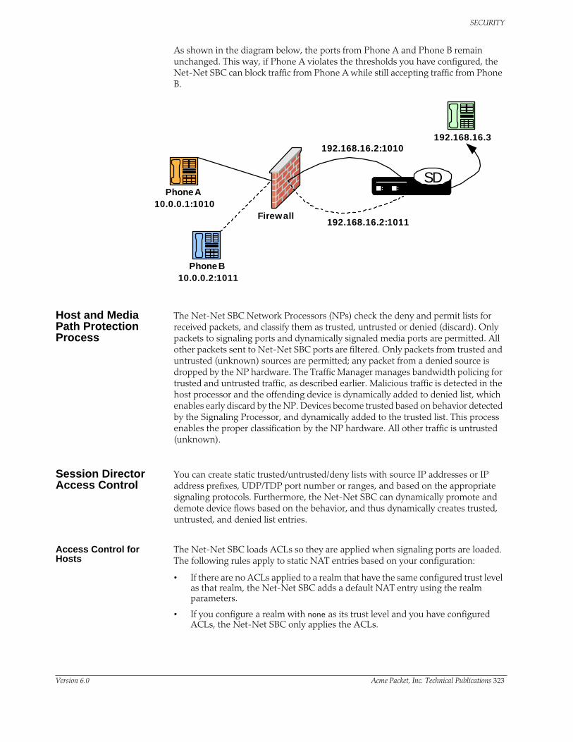
SECURITY
As shown in the diagram below, the ports from Phone A and Phone B remain unchanged. This way, if Phone A violates the thresholds you have configured, the Net-Net SBC can block traffic from Phone A while still accepting traffic from Phone B.
Host and Media Path Protection Process
The Net-Net SBC Network Processors (NPs) check the deny and permit lists for received packets, and classify them as trusted, untrusted or denied (discard). Only packets to signaling ports and dynamically signaled media ports are permitted. All other packets sent to Net-Net SBC ports are filtered. Only packets from trusted and untrusted (unknown) sources are permitted; any packet from a denied source is dropped by the NP hardware. The Traffic Manager manages bandwidth policing for trusted and untrusted traffic, as described earlier. Malicious traffic is detected in the host processor and the offending device is dynamically added to denied list, which enables early discard by the NP. Devices become trusted based on behavior detected by the Signaling Processor, and dynamically added to the trusted list. This process enables the proper classification by the NP hardware. All other traffic is untrusted (unknown).
Session Director Access Control
You can create static trusted/untrusted/deny lists with source IP addresses or IP address prefixes, UDP/TDP port number or ranges, and based on the appropriate signaling protocols. Furthermore, the Net-Net SBC can dynamically promote and demote device flows based on the behavior, and thus dynamically creates trusted, untrusted, and denied list entries.
Access Control for Hosts
The Net-Net SBC loads ACLs so they are applied when signaling ports are loaded. The following rules apply to static NAT entries based on your configuration:
• If there are no ACLs applied to a realm that have the same configured trust level as that realm, the Net-Net SBC adds a default NAT entry using the realm parameters.
• If you configure a realm with none as its trust level and you have configured ACLs, the Net-Net SBC only applies the ACLs.
SD
Firewall
Phone A10.0.0.1:1010
Phone B10.0.0.2:1011
192.168.16.3192.168.16.2:1010
192.168.16.2:1011
Version 6.0 Acme Packet, Inc. Technical Publications 323

SECURITY
• If you set a trust level for the ACL that is lower than the one you set for the realm, the Net-Net SBC will not add a separate NAT entry for the ACL.
ACLs provide access control based on destination addresses when you configure destination addresses as a way to filter traffic. You can set up a list of access control exceptions based on the source or the destination of the traffic.
For dynamic ACLs based on the promotion and demotion of endpoints, the rules of the matching ACL are applied.
Media Access Control
The media access control consists of media path protection and pinholes through the firewall. Only RTP and RTCP packets from ports dynamically negotiated through signaling (SIP) are allowed, which reduces the chance of RTP hijacking. Media access depends on both the destination and source RTP/RTCP UDP port numbers being correct, for both sides of the call.
Host Path Traffic Management
The host path traffic management consists of the dual host paths discussed earlier:
• Trusted path is for traffic classified by the Net-Net SBC as trusted. You can initially define trusted traffic by ACLs, as well as by dynamically promoting it through successful SIP registration, or a successful call establishment. You can configure specific policing parameters per ACL, as well as define default policing values for dynamically-classified flows. Traffic for each trusted device flow is limited from exceeding the configured values in hardware. Even an attack from a trusted, or spoofed trusted, device cannot impact the system.
• Untrusted path is the default for all unknown traffic that has not been statically provisioned otherwise. For example, traffic from unregistered endpoints. Pre-configured bandwidth policing for all hosts in the untrusted path occurs on a per-queue and aggregate basis.
Traffic Promotion Traffic is promoted from untrusted to trusted list when the following occurs:
• successful SIP registration for SIP endpoints
• successful RSIP response for MGCP endpoints
• successful session establishment for SIP or MGCP calls
Malicious Source Blocking
Malicious source blocking consists of monitoring the following metrics for each source:
• SIP transaction rate (messages per second)
• SIP call rate (call attempts per second)
• Nonconformance/invalid signaling packet rate
Device flows that exceed the configured invalid signaling threshold, or the configured valid signaling threshold, within the configured time period are demoted, either from trusted to untrusted, or from untrusted to denied classification.
324 Net-Net 9200 EMS Configuration Guide Version 6.0

SECURITY
Blocking Actions Blocking actions include the following:
• Dynamic deny entry added, which can be viewed through the ACLI.
• SNMP trap generated, identifying the malicious source
Dynamically added deny entries expire and are promoted back to untrusted after a configured default deny period time. You can also manually clear a dynamically added entry from the denied list using the ACLI.
Protecting Against Session Agent Overloads
You can prevent session agent overloads with registrations by specifying the registrations per second that can be sent to a session agent.
Configuring DoS SecurityThis section explains how to configure DoS protection on the Net-Net EMS.
Configuration Overview
Configuring Net-Net SBC DoS protection includes masking source IP and port parameters to include more than one match and configuring guaranteed minimum bandwidth for trusted and untrusted signaling path. You can also configure signaling path policing parameters for individual source addresses. Policing parameters are defined as peak data rate (in bytes/sec), average data rate (in bytes/sec), and maximum burst size.
You can configure deny list rules based on the following:
• ingress realm
• source IP address
• source port
• transport protocol (TCP/UDP)
• application protocol (SIP)
Changing the Default Net-Net SBC Behavior
The Net-Net SBC automatically creates permit untrusted ACLs that let all sources (address prefix of 0.0.0.0/0) reach each configured realm’s signaling interfaces, regardless of the realm’s address prefix. To deny sources or classify them as trusted, you create static or dynamic ACLs, and the global permit untrusted ACL to specifically deny sources or classify them as trusted. Doing this creates a default permit-all policy with specific deny and permit ACLs based on the realm address prefix.
You can change that behavior by configuring static ACLs for realms with the same source prefix as the realm’s address prefix; and with the trust level set to the same value as the realm. Doing this prevents the permit untrusted ACLs from being installed. You then have a default deny all ACL policy with specific static permit ACLs to allow packets into the system.
Example 1: Limiting Access to a Specific Address Prefix Range
The following example shows how to install a permit untrusted ACL of source 12.34.0.0/16 for each signalling interface/port of a realm called access. Only packets from within the source address prefix range 12.34.0.0/16, destined for the
Version 6.0 Acme Packet, Inc. Technical Publications 325

SECURITY
signaling interfaces/port of the realm named access, are allowed. The packets go into untrusted queues until they are dynamically demoted or promoted based on their behavior. All other packets are denied/dropped.
• Configure a realm called access and set the trust level to low and the address prefix to 12.34.0.0/16.
• Configure a static ACL with a source prefix of 12.34.0.0/16 with the trust level set to low for the realm named access.
Example 2: Classifying the Packets as Trusted
Building on Example 1, this example shows how to classify all packets from 12.34.0.0/16 to the realm signaling interfaces as trusted and place them in a trusted queue. All other packets from outside the prefix range destined to the realm’s signaling interfaces are allowed and classified as untrusted; then promoted or demoted based on behavior.
You do this by adding a global permit untrusted ACL (source 0.0.0.0) for each signaling interface/port of the access realm. You configure a static ACL with a source prefix 12.34.0.0/16 and set the trust level to high.
Adding this ACL causes the Net-Net SBC to also add a permit trusted ACL with a source prefix of 12.34.0.0/16 for each signaling interface/port of the access realm. This ACL is added because the trust level of the ACL you just added is high and the realm’s trust level is set to low. The trust levels must match to remove the global permit trusted ACL.
Example 3: Installing Only Static ACLs
This example shows you how to prevent the Net-Net SBC from installing the global permit (0.0.0.0) untrusted ACL.
• Configure a realm with a trust level of none.
• Configure static ACLs for that realm with the same source address prefix as the realm’s address prefix, and set the trust level to any value.
The Net-Net SBC installs only the static ACLs you configure.
Configuration Timestamp
You might see the following information on some of the configuration windows:
This is a configuration timestamp that displays last modified information for configuration changes made using Net-Net EMS.
When you make configuration changes to elements, the Last modified by field displays the following information:
• Net-Net EMS identifier
• Name of the user that made the modification
• IP address of the host machine upon which Net-Net EMS is running
• Relevant time zone information to specify how to interpret the timestamp in the Last modified date field.
For example:
326 Net-Net 9200 EMS Configuration Guide Version 6.0

SECURITY
EMS_admin_172.30.80.2_UTC
The Last modified date is displayed in the string date/time format, YYYY-MM-DD HH:MM:SS. For example 2007-11-07 15:16:05. When you make configuration changes using the Net-Net EMS, the date timestamp is specified in UTC.
If a sub-element is modified the timestamp belonging to the element is updated to indicate the modification time.
Configuring DoS SecurityThis section describes how to configure security settings on your Net-Net SBC from the Net-Net EMS. Configuring security in Net-Net EMS is handled in a different order than in the ACLI. The order of configuration in Net-Net EMS is:
• Media manager
• Realm and access control per realm
Host Access Policing
1. Click the Net-Net SBC you are configuring in the Net-Net EMS navigation tree.
The Net-Net SBC system window appears in the Net-Net EMS display pane.
2. Click the Media control tab.
3. Scroll to Signaling CPU policing.
4. Total signaling bandwidth reserved for host-path (bytes/sec)—Enter the maximum bandwidth available for this host path in bytes per second. This value also includes any Telnet and FTP traffic on media ports.
• minimum: 71,000
• maximum: 10,000,000 (default)
5. Percentage bandwidth reserved for untrusted sources (%)—Enter the percentage of signaling bandwidth guaranteed for untrusted hosts. The rest of the bandwidth is available for trusted resources, but can also be used for untrusted sources (see max-untrusted-signaling).
• minimum: 1%
• maximum: 100%
The default value is 30%.
6. Percentage of unused bandwidth available for untrusted sources (%)—Enter the percentage of signaling bandwidth that can be used by untrusted hosts. This bandwidth is only available when not being used by trusted sources.
Version 6.0 Acme Packet, Inc. Technical Publications 327

SECURITY
• minimum: 1%
• maximum: 100% (default)
7. Tolerance window size for access limit (sec)—Enter the tolerance-window size in seconds to measure host access limits. The value entered here is used to measure the invalid message rate and maximum message rate for the realm configuration.
8. Click Apply to save your configuration.
Configuring Basic Access Control for a Realm
Each host within a realm can be policed based on average rate, peak rate, and maximum burst size of signaling messages. These parameters take effect only when the host is trusted. You can also set the trust level for the host within the realm. All untrusted hosts share the bandwidth defined for the media manager: maximum untrusted bandwidth and minimum untrusted bandwidth.
1. Click Realms in the Net-Net EMS navigation tree.
The Realm window appears in the Net-Net EMS display pane.
2. Select the realm you want to configure and click Edit. The Edit Realm window appears.
3. Click the Access control tab.
4. Trust level—Select the trust level for the host in this realm from the drop-down list. The remaining textboxes area activated (unless you chose none.)
• none: host is always untrusted. It is never promoted to the trusted list or demoted to the deny list.
• low: host can be promoted to the trusted list or demoted to the deny list.
• medium: host can be promoted to the trusted list but is only demoted to untrusted. It is never added to the deny list.
328 Net-Net 9200 EMS Configuration Guide Version 6.0

SECURITY
• high: host is always trusted.
5. Max sustained rate (bytes/sec)—Enter the sustained rate in bytes per second for host path traffic from a trusted source within this realm.
• minimum: zero (0) is disabled.
• maximum: 4294967295
6. Malformed messages—Enter the acceptable invalid signaling message rate within the tolerance window. The value you enter here is only valid when the trust level is low or medium.
• minimum: zero (0) is disabled
• maximum: 4294967295
If the number of invalid messages exceeds this value within the tolerance window, the host is demoted.
7. Messages from trusted endpoints—Enter the maximum number of signaling messages the host can send within the tolerance window. The value you enter here is only valid when the trust level is low or medium.
• minimum: zero (0) is disabled.
• maximum: 4294967295
If the number of messages received exceeds this value within the tolerance window, the host is demoted.
8. Messages from untrusted endpoints—Enter the maximum number of untrusted messages the host can send within the tolerance window. Use to configure different values for trusted and un-trusted endpoints for valid signaling message parameters. Also configurable per realm.
• minimum: zero (0) is disabled
• maximum: 4294967295
The default value is 0.
9. Deny period(s)—Enter the time period in seconds after which the entry for this host is removed from the deny list.
• minimum: zero (0) seconds
• maximum: 4294967295 seconds
The default value is 30 seconds.
Version 6.0 Acme Packet, Inc. Technical Publications 329

SECURITY
10. Click Add next to the Access control exceptions area.
The Add Access control window appears.
11. Click OK. The entry appears in the access control window.
12. Select the entry and click Edit. The Edit Access control window appears.
13. Exception source—Enter the source IP address and number of address bits for the host. You do not need to specify the number of address bits if you want all 32 bits of the address to be matched.
Enter the starting port and number of port bits of the source address. You also do not need to specify the port bits if you want the exact port number matched. If you do not set the port mask value or if you set it to 0, the exact port number will be used for matching.
14. Exception destination—Enter the IP address and number of address bits for the destination. You do not need to specify the number of address bits if you want all 32 bits of the address to be matched.
Enter the port for the destination and the port bits. You also do not need to specify the port bits if you want the exact port number matched. If you do not set the port mask value or if you set it to 0, the exact port number will be used for matching.
15. Transmission protocol—Select the transport protocol for this ACL from the drop-down list.
• ALL
• TCP
• UDP
16. Application protocol—Select the application protocol for this ACL from the drop-down list.
• SIP
• H.323
• MGCP
• NONE
17. Access—Select the access control type for this ACL entry from the drop-down list.
• permit: puts the entry into the untrusted list. The entry is promoted or demoted according to the trust level set for this host.
330 Net-Net 9200 EMS Configuration Guide Version 6.0

SECURITY
• deny: puts the entry in the deny list.
18. Sustained signaling data rate (bps)—Enter the sustained rate in bytes per second for host path traffic from a trusted source within the realm.
• minimum: zero (0) bytes per second is the default. Policing is disabled.
• maximum: 4294967295
19. Trust level—Select the trust level for the host within the realm from the drop-down list.
• none: host is always untrusted. It is never promoted to the trusted list or demoted to the deny list.
• low: host can be promoted to the trusted list or demoted to the deny list.
• medium: host can be promoted to the trusted list but is only demoted to untrusted. It is never added to the deny list.
• high: host is always trusted.
20. Maximum invalid signaling messages with tolerance window—Enter the acceptable invalid signaling message rate within the tolerance window. The value you enter here is only valid when the trust level is low or medium.
• minimum: zero (0) is disabled.
• maximum: 4294967295
If the number of invalid messages exceeds this value within the tolerance window, the host is demoted.
21. Maximum signaling messages with tolerance window—Enter the maximum number of signaling messages the host can send within the tolerance window. The value you enter here is only valid when the trust level is low or medium.
• minimum: zero (0) is disabled.
• maximum: 4294967295
If the number of messages received exceeds this value within the tolerance window, the host is demoted.
22. Messages from untrusted endpoints—Enter the maximum number of untrusted messages the host can send within the tolerance window. Use to configure different values for trusted and un-trusted endpoints for valid signaling message parameters. Also configurable per realm.
• minimum: zero (0) is disabled
• maximum: 4294967295
23. Deny period(s)—Enter the time period in seconds after which the entry for this host is removed from the deny list.
• minimum: zero (0) seconds
• maximum: 4294967295 seconds
Version 6.0 Acme Packet, Inc. Technical Publications 331

SECURITY
24. Click Apply to continue.
25. Click Add, Edit, or Delete for further Access control exception configurations.
26. Click Apply to complete configuring security.
abcdefghi
j
k
332 Net-Net 9200 EMS Configuration Guide Version 6.0

SECURITY
DoS: Managing RSIPsWhen multiple MGCP clients simultaneously reboot, RSIPs flood the Net-Net SBC through an untrusted pipe. AUEPs are also processed by the Net-Net SBC through its untrusted pipe. The AUEPs contend with the RSIPs flooding in for the available untrusted bandwidth. This contention can cause AUEPs to be lost, which in turn causes the MGCP client to retry the RSIPs; and a network/call outage can occur.
All received RSIPs are funneled through a 5700 Traffic Manager application pipe.
Configuring Overload Protection for Session Agents
You can configure overload protection for session agents using the Net-Net EMS.
To configure overload protection for session agents
1. Click Session agents in the Net-Net EMS navigation pane.
The Session agent window appears in the display pane.
2. Select the session agent you want to configure and click Edit. The Edit Session agent window appears.
3. Click the Session agent constraints tab.
4. Session constraints—Click the checkbox to activate the constraint parameters.
5. Sustained rate window (sec)—Enter a number to set the sustained window period (in milliseconds) that is used to measure the sustained rate. (Refer to the max-sustain-rate information).
• minimum: zero (0) milliseconds (default value)
• maximum: 232 -1 milliseconds
6. Max. rate of registration messages sent to SA (reg/sec)—Enter a number to set the maximum number of registrations per second you want sent to the session agent. Also configurable per realm.
• minimum: zero (0) seconds (default value)
• maximum: 4294967295 seconds.
7. Click Apply.
Version 6.0 Acme Packet, Inc. Technical Publications 333

SECURITY
National Security and Emergency Preparedness for SIPThe Net-Net SBC now supports Emergency Telecommunications Service (ETS), which gives priority treatment of National Security and Emergency Preparedness (NSEP) communications for IP network infrastructures. ETS can increase the likelihood that calls, sessions, and other communications will be successfully completed when they are initiated by government-authorized users over the public network infrastructure. Legacy circuit-switched services such as Government Emergency Telecommunications Service (GETS) and Wireless Priority Service (WPS) also fall under the ETS rubric, and are now also supported on the Net-Net SBC.
To provide this support, you can enable the Net-Net SBC to act on SIP calls that contain an ETS dial number (DN) and/or the SIP Resource-Priority header that carries ETS resource values.
How It Works The Net-Net SBC identifies ETS calls by using the system’s pre-existing network management controls (NMC) functionality. With NMC and Resource-Priority header (RPH) support enabled on your system, the Net-Net SBC detects an ETS calls and provides the appropriate treatment for them.
The Net-Net SBC supports this feature by treating ETS calls based on the r-value parameter in the Resource-Priority header. The r-value is a key piece of information because it defines the resource priority that the call originator requests. The r-value parameter provides namespaces and priorities that the Net-Net SBC can manipulate in outgoing traffic.
In addition to a new RPH profile configuration containing information about how to treat RPHs, new parameters in the global SIP configuration and NMC configuration have been added. The RPH profile is applied to an NMC rule, where they determine r-values, a media policy to use, and what type of call treatment to apply. Also applies to an NMC rule, the new RPH policy configuration provides information about which r-values to insert and which to override.
Licensing To enable NSEP for SIP on your Net-Net SBC, you must obtain and install a new license.
For information about how to obtain an NSEP RPH license, contact your Acme Packet sales representative.
Matching by NMC and by RPH
When a Net-Net SBC has been enabled to act on RPH, it checks incoming requests for RPH, tries to parse that RPH, and then rejects requests in the circumstances listed below. For all of these rejections, the Net-Net SBC logs the error at the TRACE level.
• Request with multiple instances of the same namespace in the RPH—The Net-Net SBC sends out a 400 Bad Request response with the “Invalid RPH - Namespace repeated” header showing that there are multiple instances of the same namespace in the RPH.
• Request with invalid resource priority for a namespace—The Net-Net SBC sends out a 400 Bad Request response with the “Invalid RPH - Invalid rvalue: x” showing that there is an invalid resource value (where x is the invalid value).
• Request with WPS namespace, but without ETS namespace—The Net-Net SBC sends out a 400 Bad Request response with the “Invalid RPH - No ETS value” header showing that there is no ETS namespace.
334 Net-Net 9200 EMS Configuration Guide Version 6.0

SECURITY
If the Net-Net SBC successfully parses the RPH, it identifies the ETS call by checking the Request-URI of the incoming request against destination identifiers that you configure in the NMC rules. If there is a match between the request’s ETS DN and the destination value identifier in the NMC rules, the Net-Net SBC tags the call; note that NMC rules need to be configured with the rph-feature parameter set to enabled to identify an ETS call properly. If there is no match to an NMC rule, then the Net-Net SBC performs matching based on RPH by comparing resource values (r-values) in the RPH with values you set in the RPH profile configuration.
For an ETS call that matches by ETS DN and NMC rule, the Net-Net SBC checks the NMC rule to determine if it has an RPH profile (with r-values) assigned to it. If so, the Net-Net SBC continues by comparing the RPH profile’s r-values against those in the request’s RPH. In cases where the RPH does not contain a recognized value r-value, the Net-Net SBC:
• Processes the call as it normally would (as a non-ETS call) without changing the RPH if the resource priority option tag is not present in the Required header (for an INVITE only and not any other requests or response from which RPH would be deleted)
• Rejects the Request when the Require header has the resource-priority header; or, inserts an Accept Resource Priority header (ARPH) in the response if the insert arp header parameter option is enabled
However, the call goes through the Net-Net SBC as an ETS call when it is matched by ETS DN and the applicable NMC does not have an RPH profile assigned. According to the settings in the NMC rule, the Net-Net SBC either diverts or rejects such a call. And when the call matches by RPH rather than ETS DN, the Net-Net SBC applies the configured RPH profile from the relevant NMC rule.
It can be the case that non-ETS calls have RPH in their requests. Here, the Net-Net SBC call treatment is performed according to the settings in the matching RPH profile when there is no matching NMC rule. When you configure treatment as “reject,” then the Net-Net SBC rejects the call with a 417 Unknown-Resource Priority status code. When you set the treatment to either “accept” or “priority,” the Net-Net SBC allows the call to proceed as a non-ETS call or as a priority call.
The ETS r-value can appear in ACK, BYE, INFO, PRACK, REFER and UPDATE requests. In cases when it does and the session with which the request is associated is a non-ETS call, the Net-Net SBC removes the RPH from the request before forwarding it and logs a TRACE-level error. The Net-Net SBC also removes RPH from responses before forwarding them and logs a TRACE-level error when responses contain RPH headers with ETS values for non-ETS sessions.
Call Treatment This section describes how ETS calls are treated as they traverse the Net-Net SBC.
Call Treatment Description
Routing ETS calls are routed the same way as any other calls are, except when the applicable NMC rule’s treatment type is “divert,” and rule defines the next hop. This route takes precedence over other normal routes.
Local NMC ETS calls are exempt from the local NMC, including: session agent constraints, bandwidth constraints (e.g., per-realm bandwidth), per-user CAC, and CPU constraints. However, the call is subject to the ETS congestions control threshold. Licensing session constraints apply.
Version 6.0 Acme Packet, Inc. Technical Publications 335

SECURITY
Generating Egress RPH
For each ETS call, the Net-Net SBC generates RPH for the outgoing request. It forms this RPH according to the information in the NMC rule. The outgoing request types are INVITE, ACL, BYE, CANCEL, INFO, PRACK, REFER, and UPDATE.
For example, given an incoming request with the resource priority ets.0, dsn.flash and an RPH policy with an override value of wps.1,ets.1, the egress request would be sent with a resource-priority of wps.1,ets.1,dsn.flash.
The Net-Net SBC also includes RPH in the following series of responses, even when the downstream SIP entity does not respond with an RPH: 1xx, 2xx, 3xx, 4xx, 5xx, and 6xx. The 401 Unauthorized response is an exception.
Media Treatment If the RPH profile set in an NMC names a media policy, then the Net-Net SBC implements it for the ETS call. This media policy overrides any media policy set in the realm configuration.
The possible Differentiated Services Code Point (DSCP) values for an ETS call are:
• Audio—Applied to the respective media for an ETS call
• Video—Applied to the respective media for an ETS call
• SIP—Applied to the ETS calls’ SIP signaling messages, only for the egress call leg for the ETS session
Net-Net EMS Instructions and Examples
This section shows you how to configure RPH profiles and policies that enable the Net-Net SBC to act on SIP calls that have an ETS DN and/or an RPH carrying ETS resources values. There are also settings for the global SIP configuration and for the NMC rule configuration that support this feature.
ETS Call Congestion Control
ETS calls are subject to congestion control constraints that you configure specifically for this type of traffic. In the global SIP configuration, you set up one option that defines a load limit (greater than that set for normal calls).
ETS CAC Although the Net-Net SBC uses the call rate control value in the applicable NMC rule, you can also enforce call rate on a per-user basis for ETS calls.
Call Treatment Description
Request RPH Status Generated Egress RPH
Incoming request without RPH (matched by ETS DN)
Outgoing RPH value becomes the r-value set in the insert-r-value parameter in the RPH policy applied to the NMC rule.
Incoming request without RPH (matched by ETS DN)
If the insert-r-value parameter is empty in the RPH policy applied to the NMC rule or there is no RPH policy applied to the NMC rule, then the egress RPH will also not have RPH.
Incoming request has RPH
Egress RPH is the same as the ingress if the NMC rule has an RPH policy applied but the override-r-value for the policy is empty or if there is not RPH policy applied to the NMC rule.
If the override-r-value for the policy is set, then the egress RPH is set to that value.
336 Net-Net 9200 EMS Configuration Guide Version 6.0

SECURITY
Valid values for the parameters that take r-values are wps.x and ets.x, where x is 0 through 4.
Setting Up an RPH Policy
The RPH policy is a configuration on the Net-Net SBC that you apply to NMC rules. It designates the following for ETS/WPS namespaces:
• An override resource value—Resource value used to override the incoming RPH’s resource value
• An insert resource value—Resource value inserted when the Net-Net SBC does not recognize the RPH, the incoming request has no RPH, or the call is H.323 and matches an NMC rule based on the ETS DN
Note that RPH policies do not apply for DSN, DRSN, Q.735, or any other type of namespace; these remain untouched in outgoing requests.
To configure an RPH policy:
1. In the Inactive configurations area (ensure you have copied the active configuration to this area), click the Net-Net SBC you want to configure in the Net-Net EMS navigation tree.
2. Click Profiles in the Net-Net EMS navigation tree.
3. Click on the RPH policy tab. The RPH policy table appears.
4. Click Add. The Add RPH policy dialog box appears.
5. Name—Enter a name that uniquely identifies the RPH Policy. In addition, this is the value you use to identify this policy for application in the NMC rules configuration.
6. Click OK. The RPH policy you have just named appears in the RPH policy table.
Version 6.0 Acme Packet, Inc. Technical Publications 337

SECURITY
7. Click the RPH policy name for the profile you want to continue configuring, and click Edit to add r-values to the profile. The Edit RPH profile window appears.
8. R-value—To add a value that the Net-Net SBC uses to override r-values in the original RPH, click Add to the right of r-value. The Add R-values window appears, and you can enter the value you want to use.
9. Click OK. The value you entered appears in the r-value section of the Edit RPH profile window..
10. In the Edit RPH profile window, click Apply. Your r-value entry appears in the RPH profile table on the RPH profile tab.
Setting Up an RPH Profile
The RPH profile contains information about how the Net-Net SBC should act on the namespace(s) present in a Resource Priority header (if any). The list of resource values in this configuration calls out the resource values (or r-values) recognizable to the Net-Net SBC; the ETS and WPS namespaces are supported.
You also set a media policy for the RPH profile to use; it defines the Differentiated Services Code Point (DSCP) that the Net-Net SBC uses for media or signaling packets belonging to the egress call leg for the ETS session.
The call treatment parameter tells the Net-Net SBC what to do with a non-ETS call that has RPH in its request; the call can be allowed, rejected, or treated as a priority call.
To configure an RPH profile:
338 Net-Net 9200 EMS Configuration Guide Version 6.0

SECURITY
1. Click Profiles in the Net-Net EMS navigation tree.
2. Click the RPH profile tab. The RPH profile table appears.
3. Click Add. The Add RPH profile dialog box appears.
4. Name—Enter a name for this RPH Policy; this value uniquely identifies the RPH Policy. In addition, this is the value you use to apply the policy in the NMC rules configuration.
5. QoS marking profile—Choose the one you want to apply for this RPH profile from the drop-down list. The Net-Net SBC implements this QoS marking profile for the ETS call, and it overrides any QoS marking profile set in the realm configuration.
Call Treatment—Choose a call treatment method from the drop-down list for a non-ETS call that contains RPH matching it to this profile.
The valid values are:
accept—The call proceeds as it normally would (default).
reject—The Net-Net SBC rejects the call with the 417 Unknown-Resource Priority status code .
priority—The Net-Net SBC treats the call as a priority call.
6. In the Add RPH Profile window, click OK for the name, QoS marking profile, and call treatment to be applied. The values you entered appear in the RPH profile table on the RPH profile tab.
7. To Add r-values that the Net-Net SBC uses for matching purposes, highlight the RPH profile where you want to add the r-values and click Edit. The Edit RPHprofile window appears.
8. Next to R-values, click Add. The Add R-values window appears.
Version 6.0 Acme Packet, Inc. Technical Publications 339

SECURITY
9. R-value—Enter the r-value you want to use and click OK.
You can add multiple r-values to a single RPH profile by separating the r-values in the entry by commas. You must enter them in the order reflected above (a WPS and then an ETS value). A WPS call always has to have an ETS namespace.
10. When you are finished adding r-values, click Apply in the Edit RPH profile window. The values you entered appear in the RPH profile table on the RPH profile tab.
Configuring an NMC Rule for NSEP
In addition to the RPH policy and RPH profile you can set for an NMC rule, you also need to set the state of this feature for the NMC rule.
To configure NMC rule for NSEP:
1. In the Inactive configurations area (ensure you have copied the active configuration to this area), click the Net-Net SBC you want to configure in the Net-Net EMS navigation tree.
The Net-Net SBC system configuration window appears in the display pane.
2. Click the NMControl tab. The NM controls table appears.
3. In the table, highlight the NMC rule you want to configure for NSEP support and click Edit. The Edit NM controls window appears.
4. RPH enabled—Click on the RPH enabled checkbox to enable the RPH/NSEP feature..
5. RPH profile—Choose an RPH profile from the drop-down list.
340 Net-Net 9200 EMS Configuration Guide Version 6.0
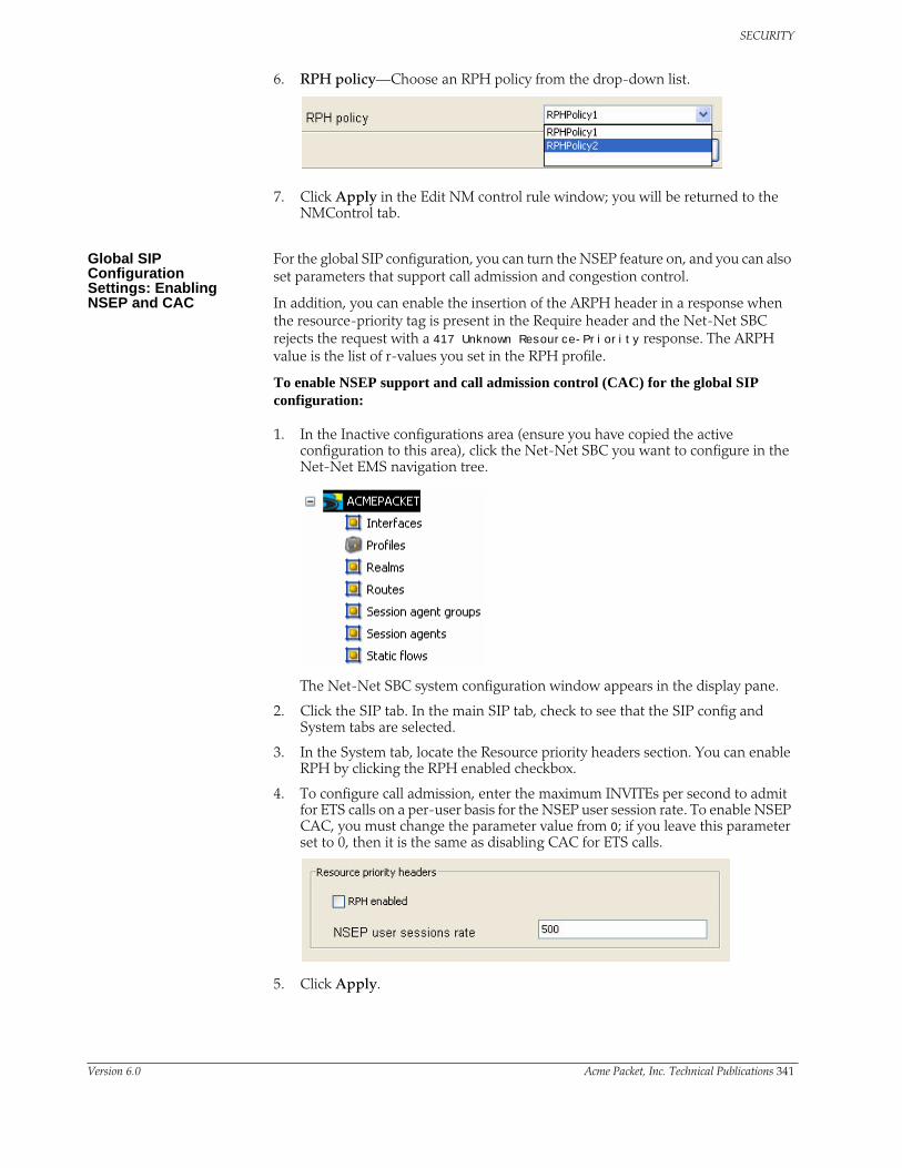
SECURITY
6. RPH policy—Choose an RPH policy from the drop-down list.
7. Click Apply in the Edit NM control rule window; you will be returned to the NMControl tab.
Global SIP Configuration Settings: Enabling NSEP and CAC
For the global SIP configuration, you can turn the NSEP feature on, and you can also set parameters that support call admission and congestion control.
In addition, you can enable the insertion of the ARPH header in a response when the resource-priority tag is present in the Require header and the Net-Net SBC rejects the request with a 417 Unknown Resource-Priority response. The ARPH value is the list of r-values you set in the RPH profile.
To enable NSEP support and call admission control (CAC) for the global SIP configuration:
1. In the Inactive configurations area (ensure you have copied the active configuration to this area), click the Net-Net SBC you want to configure in the Net-Net EMS navigation tree.
The Net-Net SBC system configuration window appears in the display pane.
2. Click the SIP tab. In the main SIP tab, check to see that the SIP config and System tabs are selected.
3. In the System tab, locate the Resource priority headers section. You can enable RPH by clicking the RPH enabled checkbox.
4. To configure call admission, enter the maximum INVITEs per second to admit for ETS calls on a per-user basis for the NSEP user session rate. To enable NSEP CAC, you must change the parameter value from 0; if you leave this parameter set to 0, then it is the same as disabling CAC for ETS calls.
5. Click Apply.
Version 6.0 Acme Packet, Inc. Technical Publications 341

SECURITY
Global SIP Configuration Settings: Enabling Congestion Control
To set the SIP option for congestion control:
1. In the Inactive configurations area (ensure you have copied the active configuration to this area), click the Net-Net SBC you want to configure in the Net-Net EMS navigation tree.
The Net-Net SBC system configuration window appears in the display pane.
2. Click the SIP tab. In the main SIP tab, check to see that the SIP config and Options and tags tabs are selected.
3. In the Options and tags tab, click Options…. The SIP option window appears.
4. For congestion control, click nsep-load-limit in the Available options list to select it.
If the CPU threshold you set here is exceeded, the Net-Net SBC rejects new ETS calls with the 503 Service Unavailable response.
5. Click to move the option to the Selected list.
6. This option requires that you specify a value for the load limit. The value you set here should be larger than the load limit value for normal calls; ETS calls are allowed even when the load limit threshold for normal calls is exceeded. The threshold value can be between 0 and 100. Using a value of 0 or 100 for this parameter disables ETS call congestion control.
342 Net-Net 9200 EMS Configuration Guide Version 6.0
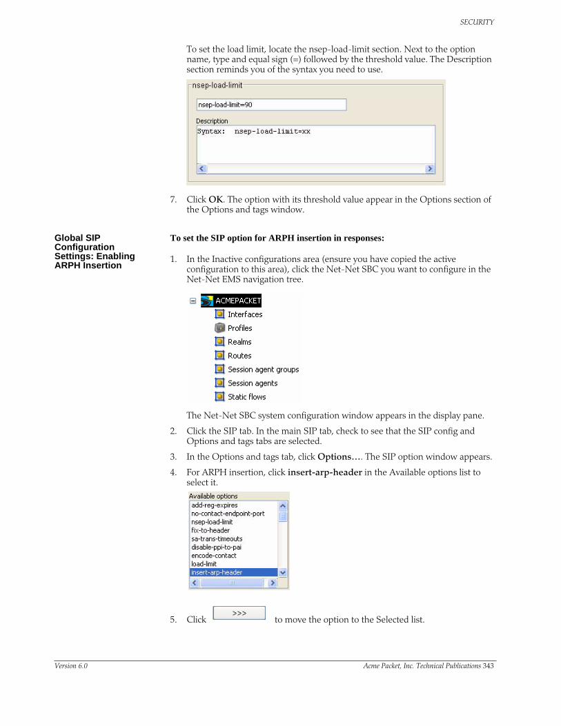
SECURITY
To set the load limit, locate the nsep-load-limit section. Next to the option name, type and equal sign (=) followed by the threshold value. The Description section reminds you of the syntax you need to use.
7. Click OK. The option with its threshold value appear in the Options section of the Options and tags window.
Global SIP Configuration Settings: Enabling ARPH Insertion
To set the SIP option for ARPH insertion in responses:
1. In the Inactive configurations area (ensure you have copied the active configuration to this area), click the Net-Net SBC you want to configure in the Net-Net EMS navigation tree.
The Net-Net SBC system configuration window appears in the display pane.
2. Click the SIP tab. In the main SIP tab, check to see that the SIP config and Options and tags tabs are selected.
3. In the Options and tags tab, click Options…. The SIP option window appears.
4. For ARPH insertion, click insert-arp-header in the Available options list to select it.
5. Click to move the option to the Selected list.
Version 6.0 Acme Packet, Inc. Technical Publications 343
SECURITY
6. Click OK. The option appears in the Options section of the Options and tags window.
Media PolicingMedia policing controls the throughput of individual media flows in the Net-Net SBC, which in turn provides security and bandwidth management functionality. The media policing feature also lets you police static flows and RTCP flows.
The term media policing refers to flows that go through the Net-Net SBC. Flows that are directed to the host application are not affected by media policing.
You can use media policing to protect against two potential security threats that can be directed against your Net-Net SBC:
• Media DoS—Once media flows are established through the Net-Net SBC, network resources are open to RTP media flooding. You can eliminate the threat of a media DoS attack by constraining media flows to absolute bandwidth thresholds.
• Bandwidth Piracy—Bandwidth policing ensures that sessions consume no more bandwidth than what is signaled for.
Policing Methods The Net-Net SBC polices real-time traffic by using Constant Bit Rate (CBR) media policing. CBR policing is used when a media flow requires a static amount of bandwidth to be available during its lifetime. CBR policing best supports real-time applications that have tightly constrained delay variation. For example, voice and video streaming are prime candidates for CBR policing.
Session Media Flow Policing
Session media encompasses RTP and RTCP flows. In order to select policing constraints for these flows, the Net-Net SBC watches for the codec specified in an SDP or H.245 message. When a match is made between the codec listed in an incoming session request and a configured media profile, the Net-Net SBC applies that media profile’s bandwidth policing constraint to the media flow about to start.
If multiple codecs are listed in the SDP message, the Net-Net SBC will use the media profile with the most permissive media policing constraints for all of the flows associated with the session. If a codec in the H.245/SDP message is not found in any configured media profile, the Net-Net SBC uses the media profile with the most permissive media policing constraints configured. If no media profiles are configured, there will be no session media flow policing.
If a mid-call change occurs, bandwidth policing is renegotiated.
Static Flow Policing Static flows can also be policed in the same way as media flows are policed. A static flow configuration redirects flows entering the Net-Net SBC on a front interface. The redirection is based on realm, source, destination, and protocol. When a flow matches the configured static flow criteria, besides being redirected toward a specified destination, its rate can also be controlled based on a static flow policing parameter. Static flow policing operates obliviously to the data contained within the flow.
344 Net-Net 9200 EMS Configuration Guide Version 6.0
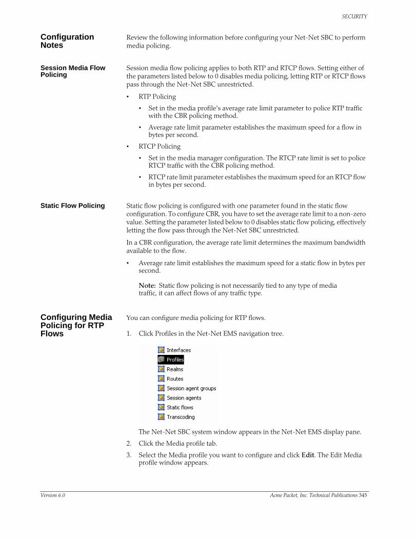
SECURITY
Configuration Notes
Review the following information before configuring your Net-Net SBC to perform media policing.
Session Media Flow Policing
Session media flow policing applies to both RTP and RTCP flows. Setting either of the parameters listed below to 0 disables media policing, letting RTP or RTCP flows pass through the Net-Net SBC unrestricted.
• RTP Policing
• Set in the media profile’s average rate limit parameter to police RTP traffic with the CBR policing method.
• Average rate limit parameter establishes the maximum speed for a flow in bytes per second.
• RTCP Policing
• Set in the media manager configuration. The RTCP rate limit is set to police RTCP traffic with the CBR policing method.
• RTCP rate limit parameter establishes the maximum speed for an RTCP flow in bytes per second.
Static Flow Policing Static flow policing is configured with one parameter found in the static flow configuration. To configure CBR, you have to set the average rate limit to a non-zero value. Setting the parameter listed below to 0 disables static flow policing, effectively letting the flow pass through the Net-Net SBC unrestricted.
In a CBR configuration, the average rate limit determines the maximum bandwidth available to the flow.
• Average rate limit establishes the maximum speed for a static flow in bytes per second.
Note: Static flow policing is not necessarily tied to any type of media traffic, it can affect flows of any traffic type.
Configuring Media Policing for RTP Flows
You can configure media policing for RTP flows.
1. Click Profiles in the Net-Net EMS navigation tree.
The Net-Net SBC system window appears in the Net-Net EMS display pane.
2. Click the Media profile tab.
3. Select the Media profile you want to configure and click Edit. The Edit Media profile window appears.
Version 6.0 Acme Packet, Inc. Technical Publications 345

SECURITY
4. Media policing—Click the checkbox to enable media policing.
5. Maximum bandwidth allowed for RTCP packets (bytes/sec)—Enter the maximum rate up to 125Mbytes per second for RTCP packet flow.
• Minimum: 0 (media policing disabled)
• Maximum: 125000000
• Default: 0
Average rate limit values for common codecs:
• PCMU—80000 Bps
• G729—26000 Bps
6. Click Apply.
Configuring Media Policing for RTCP Flows
You can configure media policing for RTCP flows by using the Net-Net EMS.
To configure media policing for RTCP flows:
1. Click the Net-Net SBC you are configuring in the Net-Net EMS navigation tree.
The Net-Net SBC system window appears in the Net-Net EMS display pane.
2. Click the Media Control tab. Scroll to Policing.
3. Media policing—Click the checkbox to enable media policing.
4. Maximum bandwidth allowed for RTCP packets (bytes/sec)—Enter the maximum rate up to 125Mbytes per second for RTCP packet flow.
5. Click Apply.
346 Net-Net 9200 EMS Configuration Guide Version 6.0

SECURITY
Configuring Media Policing for Static Flows
You can configure media policing for static flows using the Net-Net EMS.
To configure media policing for static flows:
1. Click Static flows in the Net-Net EMS navigation tree.
The Static flow window appears in the Net-Net EMS display pane.
2. Select the static flow that you want to configure and click Edit. The Edit Static flow window appears.
3. Flow Policing—Click the checkbox for Maximum-bandwidth allowed per flow (bytes/sec) to enable bandwidth policing.
4. Maximum bandwidth allowed per flow—Enter the maximum sustained rate limit in bytes per second.
• Minimum: 0 (media policing disabled)
• Maximum: 125000000
5. Click Apply.
RTP Payload Type Mapping
The Net-Net SBC maintains a default list of RTP payload types mapped to textual encoding names as defined in RFC 3551.
The following table defines the preconfigured payload type for standard encodings.
If you configure any payload type to encoding name mappings, the default mappings will be ignored. You must then manually enter all payload type mappings you use in the media-profile configuration element.
Payload Type Encoding Name Audio (A) / Video (V) Clock Rate
0 PCMU A 8000
4 G723 A 8000
8 PCMA A 8000
9 G722 A 8000
15 G728 A 8000
18 G729 A 8000
Version 6.0 Acme Packet, Inc. Technical Publications 347

SECURITY
Password Strength
Password Policy You can configure the minimum acceptable length for a password—between 8 and 64 characters—when password secure mode is enabled. For example, if you set this value to 15, then your password must be a minimum of 15 characters in length. The maximum password length is 64 characters (range is 8-64).
To increase password strength, new passwords must include at least one character from three out of four of the following character sets:
• Upper case letters
• Lower case letters
• Numbers
• Punctuation marks
However, passwords cannot contain any of the following strings in any variation of case: default, password, acme, user, admin, packet.
Note: Any change you make to the password length requirement does not go into effect until you configure a new password. Pre-existing passwords can continue to be used until you change them.
Configuring Minimum Secured Password Length
To configure the minimum password length:
6. Click the Net-Net SBC you are configuring in the Net-Net EMS navigation tree.
The Net-Net SBC system window appears in the display pane.
7. Click the Management tab.
8. Click the Password policy tab.
9. Minimum password length in secure mode—Enter a value between 8 and 64 characters that defines the minimum password length to use when in password secure mode. This parameter defaults to 8.
10. Click Apply.
348 Net-Net 9200 EMS Configuration Guide Version 6.0

SECURITY
Setting a New Password
After setting a new minimum password length, you can change your password for either the User mode or the Superuser mode. The set password command is entered as follows:
set password [login | enable | reset]
Where
• login—Sets the User mode password
• enable—Sets the Superuser mode password
• reset—resets all passwords
1. Type set password login in User mode.
ACMEPACKET# set password login
2. Enter your new password at the Enter new password prompt. Your typing will not be echoed to the screen.
Enter new password:
3. If your password doesn’t conform to the requirements, the ACLI prints a summary of your password’s characteristics so you can see how to enter a valid password. For example:
ACMEPACKET# set password login
Enter new password:
% Summary:
% password length: 9
% alpha character count: 9
% numeric character count: 0
% upper-case character count: 0
% lower-case character count: 9
% punctuation character count: 0
% invalid character count: 0
%
% Only alphabetic (upper or lower case), numeric and punctuation
% character are allowed in the password.
% Password must be 10 - 64 characters,
% and have 3 of the 4 following character classes :
% - lower case alpha
% - upper case alpha
% - numerals
% - punctuation
Enter new password:
4. Enter a new valid password, and then confirm the password.
Resetting Passwords You can use the set password [login | enable] reset command to restore the associated password to the default.
Version 6.0 Acme Packet, Inc. Technical Publications 349

SECURITY
350 Net-Net 9200 EMS Configuration Guide Version 6.0

14 Transcoding
IntroductionThe Net-Net SBC supports IP-to-IP transcoding for SIP sessions. It can connect two compressed voice streams that use different coding algorithms with one another.
This ability allows providers to:
• Handle the complexity of network connections and the range of media codecs that is endemic to VoIP with greater flexibility
• Optimize bandwidth availability by enforcing the use of high compression codecs
• Normalize traffic in the core network to a single codec
• Enact interconnection agreements between peer VoIP networks to use specified codecs
By providing transcoding capabilities at the network edge rather than employing core network resources for the same functions, the Net-Net SBC provides cost savings. It also provides a greater degree of flexibility and control over the codec(s) used in providers’ networks and the network with which they interconnect.
In addition, placing the transcoding function in the Net-Net SBC and at the network edge means that transcoding can be performed on the ingress and egress of the network. The Net-Net SBC transcodes media flows between networks that use incompatible codecs. Transcoding eliminates back-hauling traffic to a centralized location, alleviating the need for multimedia resource function processors (MRFPs) and media gateways (MGWs) to support large numbers of codecs. Decreasing the need for codec support maximizes channel density usage for the MRFPs and MGWs so that they can reserve them for their own specialized functions.
Hardware Support: the Net-Net SBC TCU
To use transcoding on your Net-Net SBC, you must have transcoding unit cards (TCUs) installed in your system. You can populate your Net-Net SBC with as few as one card or as many as three. It is possible to deploy one TCU alone, or to deploy TCU cards in either of the following redundancy schemes:
• 1+1—Active-standby mode for high availability
• 2+1—Requires three TCUs, where one card is a hot-standby for the two active cards; if one of the active cards fails, the hot-standby takes over, making failures transparent for call and media processing
The TCUs are installed into the front of the Net-Net SBC chassis. For more information about the TCU hardware and servicing the card, refer to the Net-Net 9200 Hardware Guide.
You do not need to obtain a license for this feature; transcoding is enabled automatically with your purchase of a TCU.
Version 6.0 Acme Packet, Inc. Technical Publications 337

TRANSCODING
The following example shows you the location of the TCUs in the Net-Net SBC chassis.
Channel Density Channel density depends on the following:
• Codecs used for transcoding
• Number of transcoding modules (TCMs) installed on the TCU; you can have between one and four TCMs per TCU
• Number of TCUs installed on the Net-Net SBC
• All system TCUs configured with the same number of TCMs
The following table shows the minimum channel density (bi-directional IP-IP media session; one TCU equipped with one TCM) per codec pairs.
Net-Net 9200 TCUs
338 Net-Net 9200 EMS Configuration Guide Version 6.0

TRANSCODING
The following table shows the maximum channel density per codec pairs, where there are two TCUs installed with four TCMs each.
How It WorksBecause the Net-Net SBC sits between two networks, it can perform transcoding— allowing the entities with incompatible codecs to communicate.
The Net-Net SBC’s transcoding capability is based on a SIP offer-answer model for negotiating SDP. An SDP offer can be in a SIP message such as an INVITE. The offer contains information about the codecs it would like to use. The responding network or device answers the SDP offer (answers appear in messages such as the SIP 200 OK) with its own set of supported codecs. If there are reINVITEs, then they are treated as new negotiations.
There are instances when the access and core network devices do not support the same codecs. The Net-Net SBC compares the codecs in the offer and answer, and if those codecs do not match, it enables its transcoding capability (if available). The Net-Net SBC generates a new offer media specification and returns it to the offering endpoint. If the Net-Net SBC does find matching codecs, then no transcoding is needed.
The Net-Net SBC changes the offer-answer in the model by supporting codec manipulations that add and delete codecs. The offer-answer model is broken into two-step negotiations. In transcoding policies, you can also specify the arrangement of codecs so that they are applied in a preferred order. Ingress and egress transcoding policies are determined by context:
• Ingress—An ingress transcoding policy is one specified for the offering side of a media negotiation. You can set ingress transcoding policies to act as a filter for certain codecs by configuring what the policy allows and what it does not.
• Egress—An egress transcoding policy is one specified for the answering side of a media negotiation; it is geared for the receiver.
These policies are configured and then applied to a realm, where you can set the name of the transcoding policy you want used for that realm. You can also transcode within the same realm.
About Media Formats An incoming list of media formats (in the SDP contained in SIP messages) for each media stream contains:
• A list of media formats, ordered by preference, that the offerer is capable of receiving; the media formats are codecs and any parameters associated with the codecs
• The RTP payload type numbers used to identify those media formats
Version 6.0 Acme Packet, Inc. Technical Publications 339

TRANSCODING
s
If multiple formats are listed, it means that the offerer can receive any of those formats during the session.
The list of media formats to use for a session is contained in one of the sub-fields of the SDP media line (m=). For a given media format, there can be additional associated attribute lines (a=). The a= lines can provide dynamic binding of the media format to an RTP payload type, or additional attributes to further specify the codec. In order to manipulate the offer-answer, the Net-Net SBC changes m= lines and any other associated attributes as necessary.
Transcoding Example
In this example, the access network only allows codec G.729 because of bandwidth constraints, and thus must be normalized for communication with a core network that uses G.711. The callouts describe the transcoding policies that the Net-Net SBC is applying for the access and core realms, and the actions the systems are taking in their application.
G.729 ONLY SD G.711 ONLY
Ingress transcoding policy, where add is set to G.729, allow is set to G.729
Engress transcoding policy, where add iset to G.711, allow is set to G.711
1. Initial SDP offer with G. 711 and G.729
2. SDP offer with G.711
G.711 is removed based on ingress realm’s transcoding policy.
G.729 is removed and G.711 is left based on the egress realm’s transcoding policy.
3. SDP answer with G.7114. SDP answer with G.729
G.711 is removed and G.729 is added based on the ingress realm’s transcoding policy.
340 Net-Net 9200 EMS Configuration Guide Version 6.0

TRANSCODING
Supported Codecs The table in this section lists the codecs (with their bit rates and standard frame sizes) supported for Net-Net SBC transcoding.
In addition, the following codecs are supported:
• DTMF RFC 2833
• T.38
• G.711 fallback (FAX)
Other possible values for codecs are wildcarding and none. You can wildcard codecs by entering an asterisk (*), or you can leave the setting at none.
The following table shows the allowable combinations that you can enter for transcoding policy parameters.
Optimized Transcoding Codec Pairs
In the Net-Net SBC, transcoding from any codec to another is possible; all transcoding is optimized with minimal processing and reduced latency.
Standard Bit Rate Native Frame Size
G.711 64 kbps 10 msec
G.729/A/B 8 kbps 10 msec
G.729e 8, 11.8 kbps 10 msec
iLBC 13.33 kbps15.20 kbps
30 msec20 msec
Allow Parameter Value
Add Parameter Value
Result
* None Any codec is allowed
* Codec Any codec is allowed; codecs in the Add list are added to the offer if they are not already present on the egress side
Codec Codec All codecs are removed except those specified in the Allow list; codecs in the Add list are added to the offer if they are not already present
Codec None All codecs are removed except those specified in the Allow list
None Codec All codecs are removed; codecs in the Add list are added to the offer if they are not already present
Version 6.0 Acme Packet, Inc. Technical Publications 341

TRANSCODING
Configuring TranscodingThis section describes how to configure transcoding policies on your Net-Net EMS.
When you configure transcoding on your Net-Net SBC, you want to consider:
• How to set up your ingress policies
• How to set up your egress policies
• To what realms you want to apply the transcoding policies you set up
Configuration Timestamp
You might see the following information on some of the configuration windows:
This is a configuration timestamp that displays last modified information for configuration changes made using Net-Net EMS.
When you make configuration changes to elements, the Last modified by field displays the following information:
• Net-Net EMS identifier
• Name of the user that made the modification
• IP address of the host machine upon which Net-Net EMS is running
• Relevant time zone information to specify how to interpret the timestamp in the Last modified date field.
For example:
EMS_admin_172.30.80.2_UTC
The Last modified date is displayed in the string date/time format, YYYY-MM-DD HH:MM:SS. For example 2007-11-07 15:16:05. When you make configuration changes using the Net-Net EMS, the date timestamp is specified in UTC.
If a sub-element is modified the timestamp belonging to the element is updated to indicate the modification time.
Adding New Transcoding Policies
1. Click Transcoding in the Net-Net EMS navigation tree.
The Transcoding window appears in the Net-Net EMS display pane. The window displays a table containing all configured transcoding policies saved on the Net-Net SBC.
342 Net-Net 9200 EMS Configuration Guide Version 6.0

TRANSCODING
2. Click Add. The Add Transcoding window appears.
3. Name—Enter the name you want to give this transcoding policy. The transcoding policy’s name is important not only because it uniquely identifies the policy, but because it is the name you will enter into your realm configuration’s Transcoding policy parameter. It is important to apply the correct policy to the appropriate realm.
4. Frames per packet—Enter the number of frames per packet to be advertised in the modified SDP for the realm.
5. Force ptime—Select enabled to enforce a ptime in the transcoding realm. The ptime inserted into the modified SDP will be equal to the frames per packet value multiplied by the native packetization interval of the preferred codec. .
6. Click OK. The newly created transcoding policy appears in the table in the Transcoding window.
Allowing, Adding, and Removing Codecs
The Net-Net SBC supports allowing, adding and removing codecs. Each of these operations works in the following way:
• Allow—The Allow codecs parameter takes a list of codecs that you want to pass through the Net-Net SBC; codecs not matching the items on this list are stripped.
You can wildcard this parameter to accept all supported codecs by simply entering an asterisk (*) as the parameter value.
An allowed codec can have a forced attribute, which is applicable only to an ingress transcoding policy. When you specify this attribute:
• The forced codec takes precedence over any non-forced matching codecs, even if a match is found in the answer; the forced codec (also matched) causes it to be used before the matched one(s)
• When a codec specified as forced is present in the original offer, all non-forced codecs are removed
• Add—The Add codecs parameter sets the codecs that the Net-Net SBC adds to an offer if that codec is not already there. This parameter applies only to the egress policy, which is customized for the receiver. This is the conversion that the egress side requires for communication.
Version 6.0 Acme Packet, Inc. Technical Publications 343

TRANSCODING
Allowing Codecs Codecs are added to the front of the codec list in the order specified. Added codecs are ignored if the top codec in the offer is not supported.
To allow codecs for transcoding policies:
1. Click Transcoding in the Net-Net EMS navigation tree.
The Transcoding window appears in the Net-Net EMS display pane.
2. Select the transcoding policy you want to allow codecs for and click Edit. The Edit transcoding window appears.
3. In Allow codecs, click Add. The Add allow codecs window appears.
4. allow codecs—From the drop-down list, select a codec that is allowed to pass through the Net-Net SBC. If you leave this parameter set to none (default), then only codecs specified in the Add codecs parameter are included. To allow all codecs, enter an asterisk (*).
5. Click OK.
Allowed codecs are added one at a time. To allow multiple codecs, repeat steps 3-5 for each.
Adding Codecs To add codecs to a transcoding policy:
1. Click Transcoding in the Net-Net EMS navigation tree.
The Transcoding window appears in the Net-Net EMS display pane.
344 Net-Net 9200 EMS Configuration Guide Version 6.0

TRANSCODING
2. Select the transcoding policy you want to add codecs to and click Edit. The Edit transcoding window appears.
3. In Codecs to append on egress, click Add. The Add codecs on egress window appears.
4. Codecs to append on egress—Select the codecs that you want added to the SDP offer for the egress transcoding policy from the drop-down list. If you leave this parameter set to none (its default), then the Net-Net SBC will not add codecs to the offer. This parameter cannot be wildcarded.
5. Click OK.
Codecs must be added one at a time. To add multiple codecs, repeat steps 3-5 for each.
Removing Codecs To remove codecs from a transcoding policy:
1. Click Transcoding in the Net-Net EMS navigation tree.
The Transcoding window appears in the Net-Net EMS display pane.
2. Select the transcoding policy you want to remove codecs from and click Edit. The Edit transcoding window appears.
3. In Codecs to append on egress, select the codec you want to delete and click Delete. A confirmation dialog box appears asking if you really want to delete the codec.
Version 6.0 Acme Packet, Inc. Technical Publications 345

TRANSCODING
4. Click Yes to finish deleting the codec.
Specifying an Order for Codecs
In your transcoding policy, you can specify the order of preference for codecs in the offer.
Codecs can be ordered in different ways. Your order listing cannot contain a single codec, nor can it contain a single wildcard value (*). A single wildcard value tells the Net-Net SBC to use the original order. However, you can use the wildcard in the list that you create. If there are any remaining codecs that do not match the order you enter, they are appended to the end of the list.
The following example uses letters as placeholders to show how you can manipulate the order.
Given codecs A B C D E F G:
• You can specify the order of each codec in the list. For example, you might change the order listed above to: F E D G B A and C.
• You can specify the order of part of the list, and leave the rest to be appended in the order they appear. You might only specify A D E and G. The order would then be A D E G C F. C and F are the codecs not listed, and are added to the end of the list in their original sequence: C comes first, then F.
• You can place a wildcard value by entering an asterisk (*) at the beginning, in the middle, or at the end of the ordering.
– If you want codecs D and E to appear last in the order, you would enter *DE. The resulting order would then be A B C F G D E.
– If you want codecs D and E to appear in the first and last positions in the order, you would enter D*E. The resulting order would then be D A B C F G E.
– If you want codecs D and E to appear first in the order, you would enter DE*. The resulting order would then be D E A B C F G.
Configuring Codec Order
To configure an order of preference for codecs in the offer:
1. Click Transcoding in the Net-Net EMS navigation tree.
346 Net-Net 9200 EMS Configuration Guide Version 6.0

TRANSCODING
The Transcoding window appears in the Net-Net EMS display pane.
2. Select the transcoding policy you want to specify codec order for and click Edit. The Edit transcoding window appears.
3. In Codecs order, click Add. The Add order codecs window appears.
4. Order codecs—Specify the codec order by selecting codecs from the dropdown list. You can only select one codec at a time.
5. Click OK. The codec appears in the Codecs order table. You can add multiple codecs by adding them one at a time.
6. Click the Reorder button to manipulate the order of the codecs. The Re-order TCCOrder dialog box appears.
7. Change the order of the codecs by selecting each and dragging it to where you would like it.
Version 6.0 Acme Packet, Inc. Technical Publications 347

TRANSCODING
Applying a Transcoding Policy to a Realm
Once you have configured the transcoding policies that you need, you apply them to realms. You need to know the name you gave to transcoding policy so that you can enter it into a realm configuration.
To apply a transcoding policy to a realm:
1. Click Realms in the Net-Net EMS navigation tree.
The Realm window appears in the display pane.
2. Select the realm you want to apply a transcoding policy to and click Edit. The Edit Realm window appears.
3. Select the Realm tab.
4. Transcoding policy—Select the transcoding policy you want to apply to this realm from the drop-down list. There is no default for this parameter. .
Transcoding in the Same Realm
If you want transcoding to take place within the same realm, you can enable that function in the Edit Realm window.
Note: Acme Packet recommends that you leave the Within the single realm parameter unchecked if your realm configuration’s Within this realm serviced by this Net-Net system only parameter is also left unchecked.
To transcode within a realm:
1. In the Realm window, select the realm whose transcoding policy you would like to edit. Click Edit.
2. Within the single realm—Click the checkbox to enable transcoding within the same realm.
Transcoding in the Same Network
If you want transcoding to take place within the same network, you can enable that function in the realm configuration.
To transcode within a network:
348 Net-Net 9200 EMS Configuration Guide Version 6.0

TRANSCODING
1. In the Realm window, select the realm whose transcoding policy you would like to edit and click Edit.
2. Within the same network—Click the checkbox to enable transcoding within the same network.
3. Click Apply to continue.
Version 6.0 Acme Packet, Inc. Technical Publications 349

TRANSCODING
350 Net-Net 9200 EMS Configuration Guide Version 6.0

15 High Availability
OverviewAcme Packet's Net-Net SBC currently provides intra-system high availability (HA) support. The Net-Net SBC monitors itself for internal process and network health. When it detects internal faults, the card where the fault was found transitions to standby state, while the standby card transitions to active state. This process happens without any user-perceived call loss.
Intra-System HA ArchitectureThe Net-Net SBC provides card-level component redundancy within the system chassis. Each active SPU, NPU, NIU, and MIU has a backup card that provides 1:1 redundancy. This means that for one active device, there is one available backup device. The three TCUs can be configured for either 2:1 or 1:1 redundancy. This means that either of the two TCUs can fail over to the third redundant TCU, or that the Net-Net SBC can support just one active and one standby TCU.
Each redundant card operates in hot-standby mode, capable of immediately assuming the active role. On a component failure, established calls are maintained through the system. Call signaling and media flows proceed undisturbed through a hitless failover between the active and standby units; failover times occur in as little as 50ms.
As shown in the following diagram, each functional layer has one or more redundant components, and connects to multiple components in the adjacent layer so that there are no single points of failure. For example, when an NPU card fails, the standby NPU assumes the active role and communicates with the active SPU, TCUs, and NIUs.
Version 6.0 Acme Packet, Inc. Technical Publications 349

HIGH AVAILABILITY
HA Configuration and ManagementThe Net-Net SBC continuously monitors itself to determine when a switchover should occur. A system of health scores is used to assign a severity value for system-affecting events. Switchovers occur when a minimum health score threshold is crossed, except when the standby component has a lower existing health score. The factors and thresholds have default values or may be provisioned by the system administrator.
A switchover triggers alarms, writes entries in logs, and causes SNMP traps to be issued. All notifications of these events are viewable through standard management means. In addition, LEDs on each feature card indicate whether it is active or standby.
Feature and Interface Card Redundancy
Feature and interface cards connect to each other through redundant communication paths within the Net-Net SBC chassis. Multiple internal midplane connections provide this redundancy. The midplane is a passive electrical interconnect. No active components reside on the midplane board.
Signaling Processor Redundancy
Two SPUs provide hardware redundancy for VoIP signaling processing and general system functionality. Each SPU operates in either active mode or standby mode. When the standby SPU becomes active, the active NPU, NIUs, and TCUs all begin communication with the newly active SPU. After recovery, SPUs do not revert to their previous state until another failure or a forced switchover. Since MIUs are paired with SPUs, the MIU switches over when its SPU does.
Network Processing Redundancy
Two NPUs provide network processing and forwarding redundancy on the Net-Net SBC. Each NPU operates in either active mode or standby mode. When the standby NPU becomes active, the active SPU, NIUs, and TCUs all begin communication with the newly active NPU. When a standby NPU switches to active state, no other components explicitly switchover as a result of the NPU's switchover. After recovery, NPUs do not revert to their previous state, until another failure forces switchover.
Both NPUs' hardware components, such as the network processors, traffic managers, and CAMs are fully synchronized at all times. This enables an NPU switchover to occur rapidly without the need for re-populating the newly active NPUs with call state information.
Transcoding Redundancy
The Net-Net SBC provides flexible transcoding redundancy with its three available TCUs. The TCUs by default use a 2:1 protection mechanism. This means that 2 active TCUs are backed up by a common standby TCU. Two TCUs operate in active mode and the third TCU operates in standby mode. When the standby TCU switches to active state, the active NPU communicates with the newly active TCU. When a standby TCU switches to active state, no other components explicitly switchover as a result of the TCU's switchover. After recovery, TCUs do not revert to their previous state until another failure or forced switchover.
The hardware components on the TCUs are fully synchronized at all times. Therefore, a TCU switchover occurs with no transcoding service loss for established calls and with no user-perceived impact.
350 Net-Net 9200 EMS Configuration Guide Version 6.0

HIGH AVAILABILITY
Network Interface Redundancy
The Net-Net SBC supports full media interface redundancy across its 4 NIUs. Each NIU operates in active mode or standby mode. Interfaces on an NIU will be either all active or all standby at once. All interfaces, whether active or standby, remain link up as they connect to other Ethernet ports, unless there is a link failure. NIU configuration can be either one active and one standby NIUs, two active and two standby NIUs, or two active no standby NIUs. After recovery, NIUs do not revert to their previous state, until another failure forces switchover.
Each active NIU is matched with a standby. Slot 0’s redundant NIU rests in slot 2. Slot 1’s redundant NIU rests in slot 3. The matching pair of active and standby NIUs must be the same physical interface type (quad copper or quad SFP). This is necessary because the physical cabling of active and backup interfaces must be identical, as well as common logical VLANs and virtual IP Addresses.
When cabling redundant NIUs, the active and standby interface pairs must exist in the same logical VLAN; they do not need to exist on the same physical switch.
Other than the Gateway Link Failure Detection and Recovery configuration, there is no explicit procedure to enable redundancy on an NIU.
Management Interface Redundancy
Management interface redundancy is provided by standby MIUs. Each MIU operates in either in active mode or standby mode. Each SPU is matched to a corresponding MIU. When the standby SPU assumes the active role, the MIU paired with that SPU becomes the active too. This is unlike other Net-Net SBC redundancy behaviors.
The console interface on each MIU is available at all times, regardless of the card's active or standby state. Management Ethernet interfaces use the gateway link failure and polling feature to continue using the same management IP addresses from a newly active MIU after failover. Thus, system administrators can always connect to the Net-Net SBC's management IP addresses, or connect to the standby MIU using its console port. After recovery, MIUs do not revert to their previous state until another SPU or MIU failure forces a switchover.
Each MIU is paired with an SPU; the SPU in front-panel slot 0 uses the MIU in rear-panel slot 0, the SPU in front-panel slot 1 uses the MIU in rear-panel slot 1. After an SPU failover, the MIU paired with the newly active SPU becomes active. This arrangement keeps the unique management IP addresses logically paired with their respective SPU. Note that a failure of one or both MIUs is not service-impacting, and does not affect system availability.
You can also configure link failure detection for each MIU. When configured, the Net-Net SBC pings the configured IP address; if there is no answer, then it triggers a link down alarm.
Version 6.0 Acme Packet, Inc. Technical Publications 351

HIGH AVAILABILITY
Configuring MIU Link Failure Detection
This section explains how to configure MIU link failure detection.
1. Click the Net-Net SBC you want to configure in the Net-Net EMS navigation tree.
The Net-Net SBC system window appears in the Net-Net EMS display pane.
2. Click the Management tab.
3. From the General subtab, scroll to High availability.
4. Remote IP address used to verify MU0 link health—Enter the remote IP address you want to use to verify MU0 link health.
5. Remote IP address used to verify MU1 link health—Enter the remote IP address you want to use to verify MU1 link health.
6. Click Apply.
FailoversA failover occurs when a pair of active and standby cards within the Net-Net SBC switch roles. There are two kinds failovers: automatic and manual. A manual failover is also known as a switchover because no component failure occurs.
Automatic Failovers Automatic failovers are triggered without intervention on the system administrator’s part. Net-Net SBC cards failover automatically in the following circumstances:
• When the active card’s health score of drops below the threshold you configure.
352 Net-Net 9200 EMS Configuration Guide Version 6.0

HIGH AVAILABILITY
Configuring Automatic Failover
1. Click the Net-Net SBC you want to configure in the Net-Net EMS configuration tree.
The Net-Net SBC system configuration window appears in the Net-Net EMS display pane.
2. Click the Management tab in the Net-Net SD system configuration window. The General subtab should already be selected.
3. Lock TCU HA for 2+1 operation—Click the checkbox to enable 2+1 HA operation.
4. Automatically switchover on card failure—Click the checkbox to enable automatic failover.
5. Click Apply.
Manual Switchover Manual failovers force a pair of redundant cards to trade roles. The active card becomes standby, and the standby card becomes active. In order to manually switch card roles, the following conditions must be met.
• The card to be switched over must be in one of the following states: active, standby, or becoming standby.
• A manual switchover to the active state is only allowed on a feature card in the standby or becoming standby state if it has achieved full media, signaling, and configuration synchronization.
• A manual switchover to the active state is only allowed on a card in the standby or becoming standby state if it has a health score above the value you configure for the threshold.
The switchover command causes the redundant card pair to switch roles. You supply the slot number of a card and the new role for it to assume. For example:
ACMEPACKET# switchover 0 standby
Card State Transitions
Feature cards transition through a series of states as they become active or become standby.
Note: Packet processing and transcoding only occur on an active NPU or TCU.
Version 6.0 Acme Packet, Inc. Technical Publications 353

HIGH AVAILABILITY
Gateway Link Failure Detection and RecoveryNet-Net SBCs can detect when network connections to gateways are lost and then failover to a secondary network connection. The Net-Net SBC monitors its network connectivity to the next hop by sending periodic ARP requests; this is known as a heartbeat message. When the Net-Net SBC sends an ARP request and the next hop replies with an ARP reply, the connection is considered up, and service proceeds normally.
Link Failure Detection
If the Net-Net SBC does not receive the expected ARP reply to its heartbeat ARP request within the specified timeout period, the gateway is considered unreachable and a “gateway unreachable” network-level alarm is generated. The Net-Net SBC considers the link failed, sets its interface card to standby, and fails over to the redundant card. The redundant card assumes the active role. The configured health score amount is subtracted from the interface card that experienced the gateway link failure.
NIU link detection and gateway polling is configured on a per-interface basis.
Link Failure Recovery
To produce seamless switchovers from one interface card to the other, the Net-Net SBC uses a system of shared virtual MAC and virtual IP addresses in a similar way to VRRP (virtual router redundancy protocol). When a network interface card fails over, the standby interface card sends out gratuitous ARP messages using a virtual MAC address, establishing that MAC on another physical port on the next-hop Ethernet switch or router. To the upstream device, the MAC and IP are still alive and unchanged so that existing network connections remain undisturbed.
State Description
Initial When the Net-Net SBC is booting.
Becoming Active Card is transitioning to active state. Packets cannot be processed in this state.
Active Card is active; it can handle all media, signaling, and system processing.
Becoming Standby Card is transitioning to standby role.
Standby Timeout Card times out while waiting to become standby.
Standby Card is fully synchronized with active peer card, but in standby role.
Becoming OOS Card is transitioning to Out of Service (OOS) role.
OOS Timeout Card times out while waiting to become OOS.
OOS Card is in OOS state.
Recovery Card’s transitional state before it reverts to Standby or OOS.
354 Net-Net 9200 EMS Configuration Guide Version 6.0

HIGH AVAILABILITY
The diagram below represents standard operation. NIU 0 and NIU 1 each connect to their respective VLAN on a switch.
In the following diagram, the Net-Net SBC determines that NIU 0 should be taken out of service. NIU 2 becomes active on another router and establishes itself with the same IP addresses and MAC as NIU 0 had.
The network should be configured so that the change from one L3 interface to another has no effect on VoIP service.
ARP Polling Configuration
Three parameters determine how the Net-Net SBC polls the next-hop for its Gateway Link Failure feature. The heartbeat parameter indicates the number of seconds the Net-Net SBC waits between sending ARP requests to the gateway. The retry timeout is the number of seconds that must elapse between when the Net-Net SBC sends an ARP request and does not get a response back from the gateway. When this time is exceeded, the Net-Net SBC starts counting the successive failed ARP requests. The retry count is the number of successive failed ARP requests that must accumulate before the interface is declared out of service (and the interface fails over to the redundant device).
Configuring Interface Link Detection and Gateway Polling
This section explains how to configure interface link detection and gateway polling for a single network interface.
Version 6.0 Acme Packet, Inc. Technical Publications 355

HIGH AVAILABILITY
1. Click Interfaces in the Net-Net EMS configuration tree.
The Physical interface window appears.
2. Select the physical interface you want to configure and click Edit. The Edit Physical interface window appears.
3. Select the network interface you want to configure and click Edit.
4. Click Add in the Gateway heartbeat section of the screen to create a new gateway heartbeat or if you want to edit an already configured gateway heartbeat select it and click Edit. The Edit Gateway heartbeat window appears.
5. State—Set the state to enabled to use the gateway heartbeat feature, or leave it disabled (default) to disable the feature.
6. Expected ARP message interval from gateway (sec)—Enter the number of seconds between heartbeats for this interface; this parameter defaults to 0. Heartbeats are sent at this interval as long as the interface is viable.
7. Number of ARP request retransmissions (#)—Enter the number of heartbeat retries that you want sent to the front interface gateway before it is considered unreachable; this parameter defaults to 0.
8. ARP request timeout (sec)—Enter the heartbeat retry time-out value in seconds; this parameter defaults to 1. This parameter sets the amount of time between Net-Net SBC ARP requests to establish interface gateway communication after an interface gateway failure.
9. Health score decrement - gatway or link failure—Enter the amount to subtract from the Net-Net SBC’s health score if an interface heartbeat fails; this parameter defaults to 0. If the value you set in the retry-time-out field is exceeded, this amount will be subtracted from the system’s overall health score.
356 Net-Net 9200 EMS Configuration Guide Version 6.0

HIGH AVAILABILITY
Version 6.0 Acme Packet, Inc. Technical Publications 357

HIGH AVAILABILITY
358 Net-Net 9200 EMS Configuration Guide Version 6.0

Acronym List
General Use Acronyms3GPP— 3rd-Generation Partnership Project
A AAA—Administration, Authentication, and Authorization
ACD—Automatic Call Distribution
ACL—Access Control List
ACLI—Acme Command Line Interface
ACP—Acme Control Protocol
ACK—Acknowledgement (SIP)
ADMF—ADMinistration Function
ADSL—Asymmetric Digital Subscriber Line
AF—Access Function
AFID—Access Function Identifier
AIN—Advanced Intelligent Network
ALG—Application Layer Gateway
ANI —Automatic Number Identification (ISDN)
ANSI—American National Standards Institution
AoR—Address of Record
AP—Application Protocol
API—Application Programming Interface
ANP—Access Point Name
APPN—Advanced Peer-to-Peer Networking
ARP—Address Resolution Protocol
ARQ—Admission Request (H.323)
ASCII—American Standard Code for Information Interchange
ASIC—Application-Specific Integrated Circuit
ASN—Abstract Syntax Notation
ASN.1—Abstract Syntax Notation – 1
ASP—Application Service Provider, Active Server Pages, Adjunct Service Point
ASR —Access Service Request
ATCP—Async TCP
Version 6.0 Acme Packet, Inc. Technical Publications 357
ACRONYM LIST
ATCP stack—Refers to the separate TCP stack implemented in the ATCP task.
ATCP task—Refers to the task in the system in which the ATCP stack executes.
ATCP socket—Refers to a socket used for an async TCP connection.
ATM—Asynchronous Transfer Mode
ATX—Advanced Technology Extended
B B2BUA—Back-to-Back User Agent
BBSRAM—Battery Backup Static Random Access Memory
BC—Bearer Capability
BCID—Billing Correlation Identifier
BER—Basic Encoding Rules
BGF—Border Gateway Function
BGP—Border Gateway Protocol
BHCA—Busy Hour Call Attempts
BIOS— Basic Input/Output System
BIS—Bearer-Independent Setup
BITS—Building Integrated Timing Supply
B-ICI—Broadband Inter-carrier Interface (ATM)
B-ISUP—Broadband ISDN User Part
BNF—(augmented) Backus-Naur Form
BoS—Bottom of Stack
bps—Bits per Second
BRAS—Broadband Remote Access Server
BRI—Basic Rate Interface (ISDN)
BSP— Board Support Package
BTU—British Thermal Units
C CA—Certificate Authority
CAC—Connection Administration Control (ATM)
CALEA—Communications Assistance to Law Enforcement Agencies
CAM—Content Addressable Memory
CARP—Cache Array Routing Protocol (to replace ICP)
CAS—Cordless Access Service
C-BGF—Core Border Gateway Function
CBR—Constant Bit Rate (ATM)
CC —Country Code/ Call Content
358 Net-Net 9200 EMS Configuration Guide Version 6.0

ACRONYM LIST
CCC—Call Content Connection/ Handover Interface 3 (Call Content)
CCCid—Call Content Connection Identifier
CCM—Cisco Call Manager
CD—Call Data
CDC—Call Data Connection/ Handover Interface 2 (Call Data)
CF—Collection Function
CDPN—Called Party Number
CDR—Call Detail Record
CE—Conformité Européenne (The CE marking is a European proof of conformity and is also described as "passport" that allows manufacturers and exporters to circulate products freely within the EU.)
CFM—Cubic Feet per Minute (fan speed)
CFU—Call Forwarding Unconditional
CGI—Common Gateway Interface
CIC—Carrier Indicator Code/Carrier Identification Code
CID—Caller Identification
CISSP—Certified Information Systems Security Professional
CLC—Close Logical Channel
CLCAck—Close Logical Channel Ack
Client-SI—Client-Server Information
CLEC—Competitive Local Exchange Carrier
CLI—Command-line Interface
CMIP—Common Management Information Protocol
CMIS—Common Management Information Service
CMOT—Common Management Information Services Over TCP
CMS—Call Management Server
CNM—Customer Network Management
CO—Connection Oriented
CODEC—Coder/Decoder
COPS—Common Open Policy Service
CORBA—Common Object Request Broker Architecture
CoS—Class of Service
CP—Communications Processor
CPL—Call Processing Language
CPLD—Complex Programmable Logic Device
CPM—Communications Processor Module
CPU—Central Processing Unit
Version 6.0 Acme Packet, Inc. Technical Publications 359

ACRONYM LIST
CRA—Call Routing Apparatus
CRI—Call Related Information
CRLF—Carriage Return Line Feed
CS—Circuit Switch
CSA—Client Server Architecture
CSPDN—Circuit Switched Public Data Network
CSU—Channel Service Unit
CT—Cordless Telephone
CT-1—European analogue cordless telephone system
CT-2—Second-generation cordless telephone, Digital
CTI—Computer Telephony Integration
CUG—Closed User Group
D DA—Destination Address
DAM—Data Access Method; Data Asset Management
DDD—Direct Distance Dialing
DDF—Digital Distribution Frame
DECT—Digital European Cordless Telephone
DER—Distinguished Encoding Rules
DES—Data Encryption Standard
DF—Distribution Function
DHCP—Dynamic Host Configuration Protocol
DIAMETER—a protocol for authentication, authorization, and accounting
DiffServ—Differentiated Services
DIMM—Dual In-line Memory Module
DLCI—Data Link Connection Identifier
DLSR—Delay Since Last Send Report
DN—Directory Number
DNS—Domain Name Server/Service
DOM—Document Object Model
DoS—Denial of Service
DP—Destination Port
DPCM—Differential Pulse Code Modulation
DRAM—Dynamic Random Access Memory
DS—Differentiated Services
DSA—Digital Signature Algorithm
360 Net-Net 9200 EMS Configuration Guide Version 6.0

ACRONYM LIST
DSCP—DiffServ Codepoint
DSL—Digital Subscriber Line
DSLAM—Digital Subscriber Line Access Multiplexer
DSP—Digital Signal Processing
DSS—Digital Satellite System
DSU—Digital Service Unit
dTCP—Dynamic Transmission Control Protocol
DTD—Document Type Definition
dTLS—Dynamic Transport Layer Security
DTMF—Dial Tone Multi-Frequency
E ED—Ending Delimiter
EEPROM—Electrically Erasable Programmable Read-Only Memory
EFTPOS—Electronics Funds Transfer Point of Sale
EGP—Exterior Gateway Protocol
EMB—Early Media Blocking
EMC—Electromagnetic Compatibility
EMI —Electromagnetic Interference
ENUM—Refers to the use of an E.164 number, in reverse, with domain notation (i.e., dotted).
EPROM—Erasable Programmable Read-Only Memory
ER—Edge Router
ESD—Electrostatic Discharge
ETSI—European Telecommunications Standards Institute
F FCC—Federal Communications Commission
FCP—Firewall Control Protocol
FEC—Forward Equivalence Class
FPGA—Field Programmable Gate Array
FQDN—Fully Qualified Domain Name
FS—Fast-start
FSA—Foreign SIP Agent (ACME-specific term?)
FTP—File Transfer Protocol
FTR—Flow Transform Record
G GA—Global Address
Version 6.0 Acme Packet, Inc. Technical Publications 361

ACRONYM LIST
GB—Gigabyte
GBPS—Gigabits Per Second
GigE—Gigabit Ethernet
GMII—Gig Media Independent Interface
GNU—GNUs not UNIX
GOSIP—Government Open Systems Interconnection Profile
GPS—Global Policy Server/Global Positioning System
GSA—Global System Administrator
GSM—Global Systems for Mobile Communications
GSTN—Global Switched Telephone Network
H HA—High Availability (Acme Packet redundancy solution)
HNT—Hosted NAT Traversal (Acme Packet)
HTML—Hypertext Markup Language
HTTP—Hypertext Transport Protocol
I I/O—Input/Output
IAD—Integrated Access Device
IANA—Internet Assigned Numbers Authority
IAP—Intercept Access Point
I-BCF—Interconnect Border Control Function
I-CSCF—Interrogating Call Session Control Function
ICE—In Circuit Emulator
ICMP—Internet Control Message Protocol
ICP—Internet Cache Protocol
IDS—Intrusion Detection System
IE—Information Element
IEC—International Electrotechnical Commission
IEEE—Institute of Electrical and Electronics Engineers
IESG—Internet Engineering Steering Group
IETF—Internet Engineering Task Force
IGP—Interior Gateway Protocol
IIS—Internet Information Server
ILEC —Independent Local Exchange carrier (USA)
IMS—IP Multimedia Subsystem
IN—Intelligent Network
362 Net-Net 9200 EMS Configuration Guide Version 6.0

ACRONYM LIST
IOS—Internetworking Operating System
IP—Internet Protocol (IPv4, IPv6)
IPC—Inter-process Communication
IPDR—Internet Protocol Data Record
IPSec—Internet Protocol Security
IPtel—Internet Protocol Telephony
IPv—Internet Protocol version
IS—Intercept Server
ISDN—Integrated Services Digital Network
ISO—International Organization of Standardization
ISP—Internet Service Provider
ITAD—Internet Telephony Administrative Domain
ITSP—Internet Telephony Service Provider
ITU—International Telecommunication Union
ITU-T—International Telecommunication Union Telecommunication Standardization
IVR—Interactive Voice Response
IWF—Interworking Function (referring to the Net-Net SD’s SIP-H.323 interworking)
IXC—Interexchange Carrier
J JTAG—Joint Test Action Group
JTAPI—Java telephony application programming interface
K Kb—Kilobits
KB—Kilobytes
Kbps—Kilobits per second
KEA—Key Exchange Algorithm
KTS—Key Telephone System
L LA—Local Address
LAES—Lawfully Authorized Electronic Surveillance
LAN—Local Area Network
LATA—Local Access and Transport Area
LCD—Liquid Crystal Display
LDAP—Lightweight Direct(ory) Access Protocol
Version 6.0 Acme Packet, Inc. Technical Publications 363
ACRONYM LIST
LEA—Law Enforcement Agency
LEAF—Law Enforcement Administrative Function
LEC—Local Exchange Carrier
LED—Light Emitting Diode
LEM—Local Element Manager
LEN—Local Exchange Node
LI—Lawful Intercept/ Legal Interception
LNP—Local Number Portability
LOS—Loss of Signal
LS—Location Server
LSB—Least Significant Bit
LSR—Label-switching router
M MAC— Media Access Control/ Message Authentication Code
MAN— Metropolitan Area Networks
Mb—Megabits
MB—Megabytes
MBCD—Middlebox Control Daemon
Mbone—Multicast Backbone
MC—Monitoring Center
MCU—Multi-party Conference Unit
MD5—Message Digest 5 (hash function)
MF—Media Firewall/ Mediation Function
MG—Media Gateway
MGCP—Media Gateway Communication Protocol
MHz—Megahertz
MIB—Management Information Base (TMN)
MIB II—Management Information Base II
MIBOC —Middlebox Control Protocol
MIDCOM—Middle Box Communications
MIME—Multipurpose Internet Mail Extension
MOC—Mandatory, Optional, Conditional
MoIP—Messaging over Internet Protocol
MP—Main Processor
μP—Microprocessor (subsystem)
MPLS—Multi-protocol Label Switching
364 Net-Net 9200 EMS Configuration Guide Version 6.0

ACRONYM LIST
MR—Media Router
MRCP—Media Router Control Protocol
MSB—Most Significant Bit
MSD—Master-Slave Determination
MTA—Message Transfer Agent
MTA—Multimedia Terminal Adapter
MTBF—Mean Time Between Failures
MTTR—Mean Time To Repair
MTU—Maximum Transmission Unit
MX—Mail Exchange
N N-ACD—Network Automotive Call Distribution
NANP—North American Numbering Plan
NAPT—Network Address Port Translation
NAS—Network Access Security
NAT—Network Address Translation
Nco—Network Code of Practice
NCP—Network Control Point
NCS—Network Call Signaling
NE—Network Element
NEBS—Network Equipment - Building Systems/Standards
NEMI—Network Element Management Interface
NIC—Network Interface Card
NMS—Network Management Station
NP—Network Processor
NSRG—Network Signaling Record Generator
NTE —Networking Terminating Equipment
NTP—Network Time Protocol
NTU—Networking Terminating Unit
NVRAM—Non-volatile Random Access Memory
O OAM—Operation, Administration, and Maintenance
OC—Optical Carrier
OC-n—Optical Carrier transport
OCx—Optical Carrier level
OEI—Optical Electrical Interface
Version 6.0 Acme Packet, Inc. Technical Publications 365
ACRONYM LIST
OEM—Original Equipment Manufacturer
OID—Object Identifier
OLC—Open Logical Channel
OLCAck—Open Logical Channel Ack
ONP—Open Network Provision
OS—Operating System
OSI—Open System Interconnect(ion)
OSP—Open Settlement Protocol
OSPF—Open Shortest Path First
OSS—Operation Support Systems
P PABX—Private Automatic Branch Exchange
PACS—Personal Access Communications Systems
PAT—Port Address Translation
PBX—Private Branch Exchange
P-CSCF—Proxy Call Session Control Function
PCB—Printed Circuit Board
PCDATA—Parseable Data Characters
PCI—Peripheral Component Interconnect
PCMCIA—Personal Computer Memory Card International Association
PCN—Personal Communications Network
PCS—Personal Communications Services
PD—Packet Data
PDCS—Packet Cable Distributed Call Signaling
PDH—Plesiochronous Digital Hierarchy
PDN—Public Data Network
PDN—Packet Data Network
PDP—Policy Decision Point
PDU—Protocol Data Unit (or Packet Data Unit)
PEM—Privacy Enhanced Mail
PEP—Policy Enforcement Point/Protocol Extensions Protocol
Perl—Practical Extraction Report Language
PHY—Physical Layer Device
PIB—Policy Information Base
PING—Packet Internet Groper
PINT—PSTN and IP Internetworking
366 Net-Net 9200 EMS Configuration Guide Version 6.0

ACRONYM LIST
PKCS-7—RFC 2315, Cryptographic Message Syntax, Version 1.5
PKCS-10—RFC 2314, Certificate Request Syntax, Version 1.5
PKI —Public Key Infrastructure
PMC—PCI Mezzanine Card
PNNI—Private Network Node Interface (ATM)
PNO—Public Network Operator
POP—Point of Presence
POS—Packet Over SONET
POTS—Plain Old Telephone Service
PPP—Point-to-Point Protocol
PROM—Programmable Read-Only Memory
PSTN—Public Switched Telephone Network (Telecom Network)
PTE—Packet Transform Engine
PTO—Public Telecommunications Operator
PTT—Post, Telephone, and Telegraph
PWB—Printed Wiring Board
Q QoS—Quality of Service
QSIG—Unified International Digital Corporate Network Signaling Standard
R RADIUS—Remote Authentication Dial-in User Service
RAM—Random Access Memory
RARP—Reverse Address Resolution Protocol
RAS—Remote Access Service; Registration Admission and Status (H.323)
RC2 and RC4—Rivest encryption ciphers developed for RSA Data Security
RED—Random Early Discard
REN—Ringer Equivalent Number
RFC—Request for Comments
RIP—Routing Information Protocol
RISC —Reduced Instruction Set Chip
RMON—Remote (Network) Monitoring
ROM—Read-Only Memory
RPC—Remote Procedure Call
RR—Received Report
RS-232—Recommended Standard 232 (computer serial interface, IEEE)
RSA—Rivest, Shamir, & Adleman (public key encryption technology)
Version 6.0 Acme Packet, Inc. Technical Publications 367

ACRONYM LIST
RSIP—ReStart In Progress
RSVP—Resource Reservation Protocol
RTCP—Real-time Control Protocol
RTP—Real-time Transport Protocol
RTP/AVP—Real-time Transport Protocol/Audio-Video Protocol
RTSP—Real-time Streaming Protocol
RTT—Round Trip Time
S SA—Source Address
SA—Session Agent
SAG—Session Agent Group
SBC—Session Border Controller
S-CSCF—Serving Call Session Control Function
SCE—Service Control Environment
SCP—Service Control Point
SCTP—Streaming Control Transmission Protocol
SD—(Net-Net) Session Director
SDH—Synchronous Digital Hierarchy
SDP—Session Description Protocol
SDRAM—Synchronous Dynamic Random Access Memory
SERDES—Serial De-serializer
SHA-1—Secure Hash Algorithm, a hash function used by the U.S. Government
SIG—Special Interest Group
SIM—Subscriber Identity Module
SIMM—Single In-line Memory Module
SIP—Session Initiation Protocol
SLA—Service Level Agreement
SME—Small to Medium Enterprise(s)
SMIL—Synchronized Multimedia Integration Language
SMP—Simple Management Protocol
SMTP—Simple Mail Transfer Protocol
SNMP—Simple Network Management Protocol
SOCKS—SOCKetS server
SONET—Synchronous Optical Network
SP—Source Port / Service Provider
SPAF—Service Provider Administrative Function
368 Net-Net 9200 EMS Configuration Guide Version 6.0

ACRONYM LIST
SR —(Net-Net) Session Router
SRAM—Static Random Access Memory
SRS—Session Routing System
SRV—Resource record for servers (DNS)
SS—Slow-start
SS7—Signaling System 7
SSH—Secured Shell or Secure Socket Shell
SSL—Secure Socket Layer
SSP—Service Switching Point
sTCP—Static Transmission Control Protocol
STL—Standard Template Library
sTLS—Static Transport Layer Security
STP—Signal Transfer Point; Service Transfer Point
SVC—Signaling Virtual Channel (ATM)
SVC—Switched Virtual Circuit (Packet Switching)
T TA—Terminal Adapter (ISDN)
TAC—Terminal Access Control
TACACS+—Terminal Access Controller Access Control System
TAPI—Telephony Application Program Interface
TAXI—Transparent Asynchronous Transmitter/Receiver Interface
TCB—Task Control Bar/Task Control Block
TCI—Tag Control Identifier
TCP—Transmission Control Protocol
TCP/IP—Transmission Control Protocol /Internet Protocol
TCS—Terminal Capability Set
TEN—Transit Exchange Node
TFTP—Trivial File Transfer Protocol
TLS—Transport Layer Security (same as SSL)
TLV —Tag Length Value
TM—Traffic Manager
TMN—Telecommunications Management Network
ToS—Type of Service
TRIB—Telephony Routing Information Base
TRIP—Telephony Routing over IP
TS—Time Slot
Version 6.0 Acme Packet, Inc. Technical Publications 369

ACRONYM LIST
TSAP—Transport Service Access Point
TSAPI —Telephony Server API
TTL—Time to Live
U UA—User Agent
UAC—User Agent Client
UAS—User Agent Server
UDP—User Datagram Protocol
UE—User Equipment
UL—Underwriters Laboratories
UMTS—Universal Mobile Telecommunications Systems
UNI—User-to-Network Interface
UPS—Uninterruptible Power Supply
UPT—Universal Portable Telephone
URI—User Resource Identifier
URL—Uniform Resource Location
UTC—Coordinated Universal Time
UTP—Unshielded Twisted Pair
V VAC—Volts Alternating Current
VANS—Value Added Network Services
VAR—Value Added Reseller
VarBind—Variable Binding
VBR—Variable Bit Rate
VC—Virtual Channel (ATM)/Virtual Container (SDH)
VCC—Virtual Channel Connection (ATM)
VCI—Virtual Channel Identifier
VDC—Volts Direct Current
VFD—Vacuum Florescent Display
VLAN—Virtual Local Area Network
VLL—Virtual Leased Lines
VoIP—Voice Over Internet Protocol
VP—Virtual Path
VPC—Virtual Path Connection
VPI—Virtual Path Identifier
VPN—Virtual Private Network
370 Net-Net 9200 EMS Configuration Guide Version 6.0

ACRONYM LIST
VSA—Vendor-specific Attribute (RADIUS extension)
VTOA—Voice and Telephony over ATM
W WAN—Wide Area Network
WLL—Wavelength Division Multiplex
X XE—Translation Engine
XML—Extensible Markup Language
XSM—External Search Machine
Y (None to list.)
Z ((None to list.)
Signaling Protocol AcronymsThe acronyms used in this guide’s discussion of H.323 signaling services and IWF services.
H.323 We use the acronyms listed below to refer to H.323 signaling messages and other related H.323 behavior.
ACF—Admission Confirm
Alerting—Message used when called party alerted
ARQ—Admission Request
Call Proceeding—Message used when call established
CLC—Close Logical Channel
CLC Ack—Close Logical Channel Acknowledgment
Connect—Message used when called party accepts call
GRQ—Gatekeeper Discovery
IRQ—Information Request
IRR—Information Request Response
LCF—Location Confirm
LRJ—Location Reject
LRQ—Location Request
M/S Det.—Master/Salve Determination
OLC—Open Logical Channel
OLC Ack—Open Logical Channel Acknowledgment
Version 6.0 Acme Packet, Inc. Technical Publications 371

ACRONYM LIST
RAS—Registration, Admission, and Status
RCF—Registration Confirm
Release Complete—Message used when call is released, signaling channel open
RRJ—Registration Reject
RRQ—Registration Request
Setup—Message used to request connection
TCS—Terminal Capability Set
UCF—Unregistration Confirm
URJ—Unregistration Reject
URQ—Unregistration Request
372 Net-Net 9200 EMS Configuration Guide Version 6.0