Embed Size (px)
Citation preview
NetApp® CN1610 SwitchAdministrator’s Guide
NetApp, Inc.495 East Java DriveSunnyvale, CA 94089 U.S.A.Telephone: +1 (408) 822-6000Fax: +1 (408) 822-4501Support telephone: +1 (888) 463-8277 Documentation comments: [email protected] Information Web: www.netapp.com
Part number: 215-06287_D0 August 2017
Copyright and trademark information
Copyright information
Copyright © 1994–2017 NetApp, Inc. All rights reserved. Printed in the U.S.
No part of this document covered by copyright may be reproduced in any form or by any means—graphic, electronic, or mechanical, including photocopying, recording, taping, or storage in an electronic retrieval system—without prior written permission of the copyright owner.Software derived from copyrighted NetApp material is subject to the following license and disclaimer:
THIS SOFTWARE IS PROVIDED BY NETAPP "AS IS" AND WITHOUT ANY EXPRESS ORIMPLIED WARRANTIES, INCLUDING, BUT NOT LIMITED TO, THE IMPLIEDWARRANTIES OF MERCHANTABILITY AND FITNESS FOR A PARTICULAR PURPOSE,WHICH ARE HEREBY DISCLAIMED. IN NO EVENT SHALL NETAPP BE LIABLE FOR ANYDIRECT, INDIRECT, INCIDENTAL, SPECIAL, EXEMPLARY, OR CONSEQUENTIALDAMAGES (INCLUDING, BUT NOT LIMITED TO, PROCUREMENT OF SUBSTITUTEGOODS OR SERVICES; LOSS OF USE, DATA, OR PROFITS; OR BUSINESS INTERRUPTION)HOWEVER CAUSED AND ON ANY THEORY OF LIABILITY, WHETHER IN CONTRACT,STRICT LIABILITY, OR TORT (INCLUDING NEGLIGENCE OR OTHERWISE) ARISING INANY WAY OUT OF THE USE OF THIS SOFTWARE, EVEN IF ADVISED OF THEPOSSIBILITY OF SUCH DAMAGE.
NetApp reserves the right to change any products described herein at any time, and without notice.NetApp assumes no responsibility or liability arising from the use of products described herein, except as expressly agreed to in writing by NetApp. The use or purchase of this product does not convey a license under any patent rights, trademark rights, or any other intellectual property rights of NetApp.
Trademark
information
Active IQ, AltaVault, Arch Design, ASUP, AutoSupport, Campaign Express, Clustered Data ONTAP, Customer Fitness, Data ONTAP, DataMotion, Element, Fitness, Flash Accel, Flash Cache, FlashPool, FlexArray, FlexCache, FlexClone, FlexPod, FlexScale, FlexShare, FlexVol, FPolicy, Fueled by SolidFire, GetSuccessful, Helix Design, LockVault, Manage ONTAP, MetroCluster, MultiStore, NetApp, NetApp Insight, OnCommand, ONTAP, ONTAPI, RAID DP, RAID-TEC, SANscreen, SANshare, SANtricity, SecureShare, Simplicity, Simulate ONTAP, Snap Creator, SnapCenter, SnapCopy, SnapDrive, SnapIntegrator, SnapLock, SnapManager, SnapMirror, SnapMover, SnapProtect, SnapRestore, Snapshot, SnapValidator, SnapVault, SolidFire, SolidFire Helix, StorageGRID, SyncMirror, Tech OnTap, Unbound Cloud, and WAFL and other names are trademarks or registered trademarks of NetApp, Inc., in the United States, and/or other countries. All other brands or products are trademarks or registered trademarks of their respective holders and should be treated as such. A current list of NetApp trademarks is available on the web. http://www.netapp.com/us/legal/netapptmlist.aspx
The product described in this manual may be protected by one or more U.S. patents, foreign patents,or pending applications.
RESTRICTED RIGHTS LEGEND: Use, duplication, or disclosure by the government is subject torestrictions as set forth in subparagraph (c)(1)(ii) of the Rights in Technical Data and ComputerSoftware clause at DFARS 252.277-7103 (October 1988) and FAR 52-227-19 (June 1987).

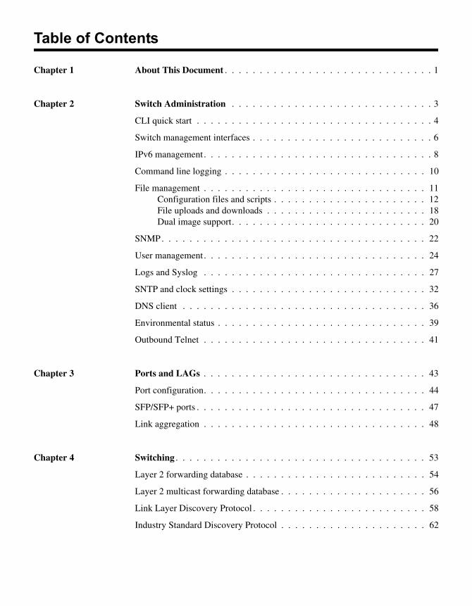
Table of Contents
Chapter 1 About This Document . . . . . . . . . . . . . . . . . . . . . . . . . . . . . . 1
Chapter 2 Switch Administration . . . . . . . . . . . . . . . . . . . . . . . . . . . . . 3
CLI quick start . . . . . . . . . . . . . . . . . . . . . . . . . . . . . . . . . . 4
Switch management interfaces . . . . . . . . . . . . . . . . . . . . . . . . . . 6
IPv6 management. . . . . . . . . . . . . . . . . . . . . . . . . . . . . . . . . 8
Command line logging . . . . . . . . . . . . . . . . . . . . . . . . . . . . . 10
File management . . . . . . . . . . . . . . . . . . . . . . . . . . . . . . . . 11Configuration files and scripts . . . . . . . . . . . . . . . . . . . . . . 12File uploads and downloads . . . . . . . . . . . . . . . . . . . . . . . 18Dual image support. . . . . . . . . . . . . . . . . . . . . . . . . . . . 20
SNMP. . . . . . . . . . . . . . . . . . . . . . . . . . . . . . . . . . . . . . 22
User management. . . . . . . . . . . . . . . . . . . . . . . . . . . . . . . . 24
Logs and Syslog . . . . . . . . . . . . . . . . . . . . . . . . . . . . . . . . 27
SNTP and clock settings . . . . . . . . . . . . . . . . . . . . . . . . . . . . 32
DNS client . . . . . . . . . . . . . . . . . . . . . . . . . . . . . . . . . . . 36
Environmental status . . . . . . . . . . . . . . . . . . . . . . . . . . . . . . 39
Outbound Telnet . . . . . . . . . . . . . . . . . . . . . . . . . . . . . . . . 41
Chapter 3 Ports and LAGs . . . . . . . . . . . . . . . . . . . . . . . . . . . . . . . . 43
Port configuration. . . . . . . . . . . . . . . . . . . . . . . . . . . . . . . . 44
SFP/SFP+ ports . . . . . . . . . . . . . . . . . . . . . . . . . . . . . . . . . 47
Link aggregation . . . . . . . . . . . . . . . . . . . . . . . . . . . . . . . . 48
Chapter 4 Switching . . . . . . . . . . . . . . . . . . . . . . . . . . . . . . . . . . . . 53
Layer 2 forwarding database . . . . . . . . . . . . . . . . . . . . . . . . . . 54
Layer 2 multicast forwarding database . . . . . . . . . . . . . . . . . . . . . 56
Link Layer Discovery Protocol . . . . . . . . . . . . . . . . . . . . . . . . . 58
Industry Standard Discovery Protocol . . . . . . . . . . . . . . . . . . . . . 62
IGMP snooping . . . . . . . . . . . . . . . . . . . . . . . . . . . . . . . . . 66
Jumbo frames . . . . . . . . . . . . . . . . . . . . . . . . . . . . . . . . . . 69
Port mirroring. . . . . . . . . . . . . . . . . . . . . . . . . . . . . . . . . . 70
Flow-based mirroring. . . . . . . . . . . . . . . . . . . . . . . . . . . . . . 72
Storm control . . . . . . . . . . . . . . . . . . . . . . . . . . . . . . . . . . 74
Flow control . . . . . . . . . . . . . . . . . . . . . . . . . . . . . . . . . . 76
Chapter 5 Multiple Spanning Tree Protocol. . . . . . . . . . . . . . . . . . . . . . . 79
MSTP overview. . . . . . . . . . . . . . . . . . . . . . . . . . . . . . . . . 80
MSTP functional description . . . . . . . . . . . . . . . . . . . . . . . . . . 81
MSTP operation in the network . . . . . . . . . . . . . . . . . . . . . . . . 87
MSTP CLI show commands . . . . . . . . . . . . . . . . . . . . . . . . . . 93
MSTP configuration example . . . . . . . . . . . . . . . . . . . . . . . . . 94
Chapter 6 VLANs . . . . . . . . . . . . . . . . . . . . . . . . . . . . . . . . . . . . . 95
Basic VLAN configuration . . . . . . . . . . . . . . . . . . . . . . . . . . . 96
Protocol-based VLANs . . . . . . . . . . . . . . . . . . . . . . . . . . . . .100
MAC-based VLANs . . . . . . . . . . . . . . . . . . . . . . . . . . . . . .104
IP subnet-based VLANs . . . . . . . . . . . . . . . . . . . . . . . . . . . .106
Double VLAN tagging . . . . . . . . . . . . . . . . . . . . . . . . . . . . .109
Chapter 7 Quality of Service . . . . . . . . . . . . . . . . . . . . . . . . . . . . . . .115
Class of service (CoS) queue mapping . . . . . . . . . . . . . . . . . . . . .116
CoS queue configuration . . . . . . . . . . . . . . . . . . . . . . . . . . . .119
QoS map and queue configuration example . . . . . . . . . . . . . . . . . .120
Differentiated services (DiffServ) . . . . . . . . . . . . . . . . . . . . . . .123
Chapter 8 Security Features . . . . . . . . . . . . . . . . . . . . . . . . . . . . . . .131
Denial of service and other protections. . . . . . . . . . . . . . . . . . . . .132
Access control lists . . . . . . . . . . . . . . . . . . . . . . . . . . . . . . .134
IEEE 802.1X . . . . . . . . . . . . . . . . . . . . . . . . . . . . . . . . . .140
SSH . . . . . . . . . . . . . . . . . . . . . . . . . . . . . . . . . . . . . . .148
RADIUS . . . . . . . . . . . . . . . . . . . . . . . . . . . . . . . . . . . .150
TACACS+ . . . . . . . . . . . . . . . . . . . . . . . . . . . . . . . . . . .154
Glossary . . . . . . . . . . . . . . . . . . . . . . . . . . . . . . . . . . . .157
Index . . . . . . . . . . . . . . . . . . . . . . . . . . . . . . . . . . . . . .161

Chapter 1: About This Document
1
About This DocumentPurpose This guide provides examples of how to use the NetApp® CN1610 cluster network switch in a typical network. This document describes the switch features and includes information about using the command-line interface (CLI) to configure them.
Additional documentation
The following documentation provides additional information about the switch FASTPATH software:
◆ The CN1610 Network Switch CLI Command Reference describes the commands available from the command-line interface (CLI) for managing, monitoring, and configuring the switch.
◆ The 10G Cluster-Mode Switch Installation Guide provides basic information to install the switch and perform initial configuration.
◆ Release notes detail the platform-specific functionality of the software packages, including known issues and workarounds.
1

2 About This Document
Chapter 2: Switch Administration
2
Switch AdministrationAbout this chapter This chapter provides information about administering the switch, including using the command-line interface (CLI), configuring basic switch settings, and managing the system configuration files.
Topics in this chapter
This chapter includes the following topics:
◆ “CLI quick start” on page 4
◆ “Switch management interfaces” on page 6
◆ “IPv6 management” on page 8
◆ “Command line logging” on page 10
◆ “File management” on page 11
◆ “Configuration files and scripts” on page 12
◆ “File uploads and downloads” on page 18
◆ “Dual image support” on page 20
◆ “SNMP” on page 22
◆ “User management” on page 24
◆ “Logs and Syslog” on page 27
◆ “SNTP and clock settings” on page 32
◆ “DNS client” on page 36
◆ “Environmental status” on page 39
◆ “Outbound Telnet” on page 41
3
CLI quick start
About this section This section provides a brief introduction to using the CLI.
NoteFor detailed information about CLI commands, see the Network Switch CLI Command Reference.
Connecting to the CLI
To begin using the CLI, follow these steps:
1. Connect to the CLI through the serial console or a Telnet/SSH connection, as described in the Cluster-Mode Switch Installation Guide.
The following prompt displays:
User >
2. Enter admin as the default user name.
3. Press Enter when prompted for a password. (There is no password by default.)
The following prompt displays:
(CN) >
The initial command mode is User EXEC mode. Commands are available in this mode for viewing switch data. These commands are also available, along with many others, in Privileged EXEC mode.
4. Enter enable to enter Privileged EXEC mode. (By default, there is no password for entering into Privileged EXEC mode; however, one can be configured.)
The following prompt displays:
(CN) #
Command modes Different command modes offer different sets of commands. The prompt changes to indicate the command mode.
In Privileged EXEC mode, you can enter commands to view switch information, configure some system-level functions, and enter into other command modes.
4 CLI quick start
For example, you can enter vlan database to enter VLAN Config mode, where you can create and configure VLANs. The prompt displays as follows:
(CN) (Vlan)#
From Privilege Exec mode, you can also enter configure (or simply config) to enter Global Config mode. In Global Config mode, you can enter commands to configure global switch settings and enter into all other configuration modes. For example, the following command sequence enters Global Config mode (from Privileged EXEC mode), and then enters Interface Config mode for port 0/5.
(CN) #config
(CN) (Config)#interface 0/5
(CN) <Interface 0/5>#
You can also enter “show” commands while in Global Config mode.
In Interface Config mode, you can enter commands to configure the specified interface.
NoteSee the Network Switch CLI Command Reference for a list of all command modes and instructions on entering them.
Using the no form of a command
The no keyword is a specific form of an existing command and does not represent a new or distinct command. Almost every configuration command has a no form. In general, use the no form to reverse the action of a command or reset a value back to the default.
For example, the no shutdown configuration command reverses the shutdown of an interface. Use the command without the keyword no to reenable a disabled feature or to enable a feature that is disabled by default.
Entering commands and getting help
The CLI automatically finishes spelling a command when you type enough letters to uniquely identify the command keyword. Once you have entered enough letters, press the SPACEBAR or TAB key to complete the word.
To view a list of available commands in the current mode, enter a question mark. To see the available parameters and variables for a command, type in the command keyword followed by a question mark.
Chapter 2: Switch Administration 5
Switch management interfaces
Overview The switch can be managed by using a command-line interface (CLI) or SNMP.
You can use any of the following methods to access the CLI:
◆ A serial connection through the console port using a terminal emulator.
◆ An in-band connection through any port using Telnet or SSH. With an in-band connection, the management data is switched along with ordinary switch traffic, and is forwarded to the network interface (a logical IP interface configured on the switch).
A management VLAN is associated with the network interface, enabling segregating of management traffic and restricting access.
To use Telnet, you must assign a management IP address to the network interface. You can assign IP information statically or configure the switch to obtain it dynamically using DHCP/BOOTP.
NoteSee the Cluster-Mode Switch Installation Guide for instructions on accessing the CLI through the serial port or Telnet/SSH.
You can also access switch information by using SNMP to view items in the supported MIBs. See “SNMP” on page 22 for more information.
The switch allows multiple concurrent Telnet and SNMP sessions.
All management interfaces are enabled by default. CLI access through IP and SNMP access can be disabled by the administrator. CLI access through the serial console is always available.
NoteManagement access through IPv6 is also supported. See “IPv6 management” on page 8 for more information.
BOOTP/DHCP client functionality
The BOOTP protocol allows a device to solicit and receive configuration data and parameters from a suitable server. DHCP is an extension to BOOTP that enables receiving additional setup parameters from a network server upon system
6 Switch management interfaces
startup. BOOTP stops operating once an IP address is obtained, but DHCP continues to operate on an ongoing basis. For example, the IP address assigned to the system has a lease time that may expire, and can be renewed on-the-fly.
The system incorporates BOOTP and DHCP clients that can solicit an IP address to use as the system management IP address. The system uses BOOTP by default; however, the administrator can configure the switch to use DHCP, or can assign a static IP address to the network interface.
DHCP/BOOTP requests are broadcast out of all ports that are members of the management VLAN. The default management VLAN is VLAN 1.
Defaults The BOOTP/DHCP client is enabled by default.
CLI show commands
You can use the following show command in Privileged EXEC mode to view information about switch management interfaces:
For more information on the BOOTP/DHCP commands, see the Network Switch CLI Command Reference.
Configuration example
The following commands change the protocol for the network interface from the default, BOOTP, to none, statically configure the switch IP information, and change the management VLAN to VLAN 100:
Command Description
show network Displays configuration settings associated with the switch's network interface.
(CN) # network protocol none(CN) # network parms 10.17.21.4 255.255.255.0 10.17.21.1(CN) # network mgmt_vlan 100
Chapter 2: Switch Administration 7
IPv6 management
Feature overview IPv6 features can be configured through the CLI and SNMP. The following management protocols and applications can operate over IPv6:
◆ Pingv6
◆ Traceroutev6
◆ TFTP
◆ SSH
◆ SSL
◆ Telnet
◆ SNMP
For ICMPv6, the switch supports error PDU generation, path MTU, echo request/reply, and redirect.
For SNMP, the switch supports the IPv6 MIB, the ICMPv6 MIB, and private MIB extensions.
The CN switch supports router advertisement as an integral part of IPv6. Numerous options are available, including stateless/stateful address configuration, router and address lifetimes, and neighbor discovery timer control.
The switch also supports Ethernet and tunnel interfaces. For Ethernet, the switch supports link-local address mapping and multicast address mapping. The tunnel interface functionality supports link-local address mapping but not general neighbor discovery, since the interface is not considered to have a link-layer address. Multiple global addresses can be configured on each interface.
IPv6 management can be enabled out-of-band over the service port or in-band as logical management interfaces (network interfaces) over the switch ports. The IP stack's routing table contains both IPv6 routes associated with the management interfaces and IPv6 routes associated with routing interfaces. If routes to the same destination (such as a default route) are learned on both a management interface and a routing interface, the routing interface route is preferred.
Defaults IPv6 management is enabled by default.
8 IPv6 management
CLI show commands
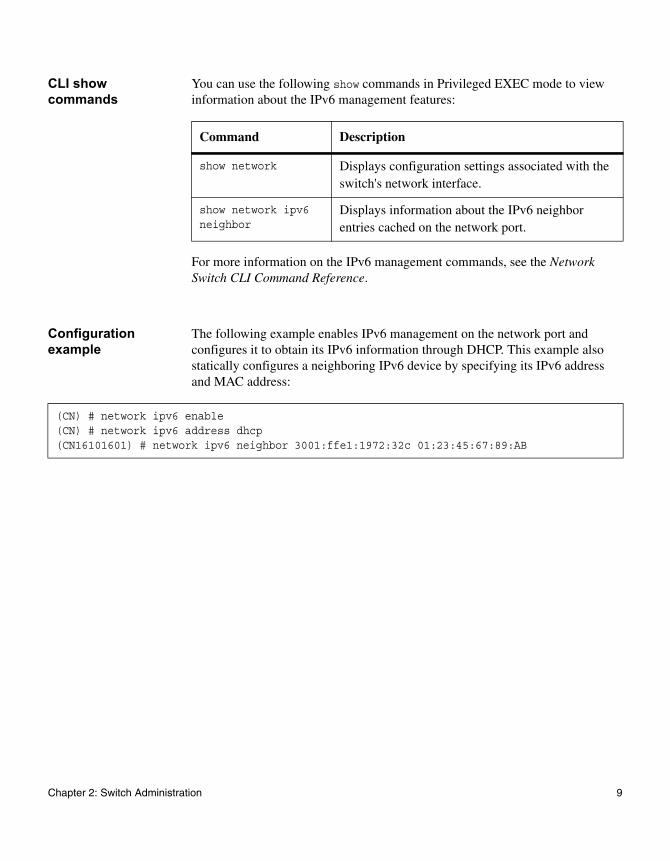
You can use the following show commands in Privileged EXEC mode to view information about the IPv6 management features:
For more information on the IPv6 management commands, see the Network Switch CLI Command Reference.
Configuration example
The following example enables IPv6 management on the network port and configures it to obtain its IPv6 information through DHCP. This example also statically configures a neighboring IPv6 device by specifying its IPv6 address and MAC address:
Command Description
show network Displays configuration settings associated with the switch's network interface.
show network ipv6 neighbor
Displays information about the IPv6 neighbor entries cached on the network port.
(CN) # network ipv6 enable(CN) # network ipv6 address dhcp(CN16101601) # network ipv6 neighbor 3001:ffe1:1972:32c 01:23:45:67:89:AB
Chapter 2: Switch Administration 9
Command line logging
Feature overview You can configure the switch to automatically create a log of configuration commands as you enter them. A command log can provide the system operators with a detailed view of the commands executed. The command log file is saved locally on the switch along with other system logs.
You can enable and disable command logging. By default, it is disabled.
Logging severity The system associates a severity level with system events that are written to the log. When CLI commands are executed and written to the log, they are assigned a nonconfigurable severity of SEVERITY_NOTICE.
Defaults Command line logging is disabled by default.
Configuration example
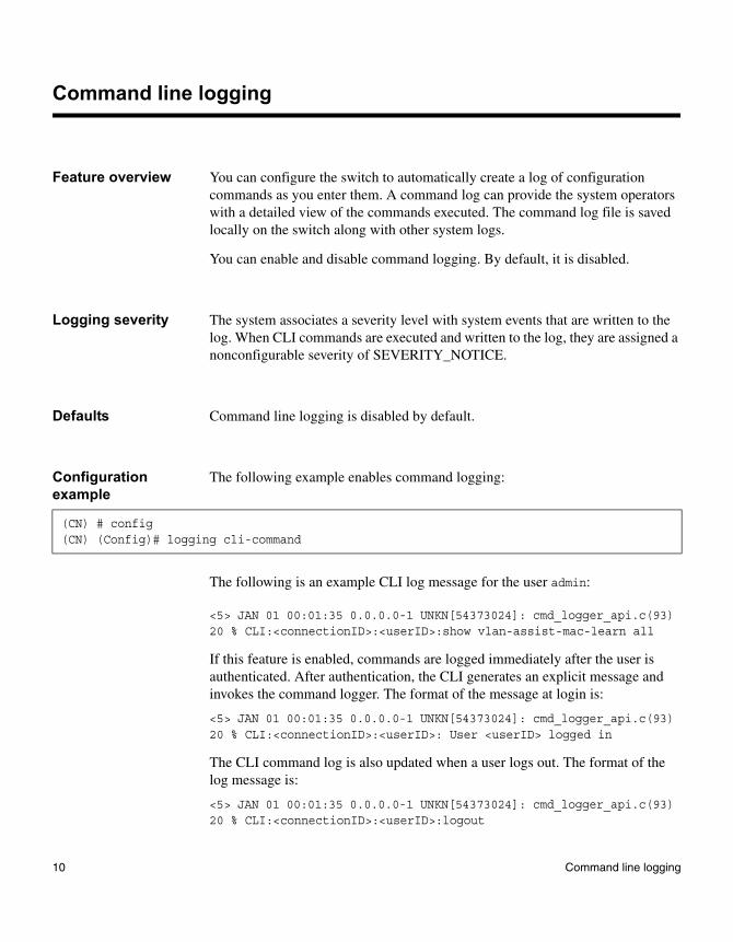
The following example enables command logging:
The following is an example CLI log message for the user admin:
<5> JAN 01 00:01:35 0.0.0.0-1 UNKN[54373024]: cmd_logger_api.c(93) 20 % CLI:<connectionID>:<userID>:show vlan-assist-mac-learn all
If this feature is enabled, commands are logged immediately after the user is authenticated. After authentication, the CLI generates an explicit message and invokes the command logger. The format of the message at login is:
<5> JAN 01 00:01:35 0.0.0.0-1 UNKN[54373024]: cmd_logger_api.c(93) 20 % CLI:<connectionID>:<userID>: User <userID> logged in
The CLI command log is also updated when a user logs out. The format of the log message is:
<5> JAN 01 00:01:35 0.0.0.0-1 UNKN[54373024]: cmd_logger_api.c(93) 20 % CLI:<connectionID>:<userID>:logout
(CN) # config(CN) (Config)# logging cli-command
10 Command line logging
File management
Overview The switch FASTPATH software has a user-accessible file system to manage the various files needed for its operation. The file system contains the application software files and a configuration file that is restored each time the switch boots.
This section includes the following topics:
◆ “Configuration files and scripts” on page 12
◆ “File uploads and downloads” on page 18
◆ “Dual image support” on page 20
Chapter 2: Switch Administration 11
File managementConfiguration files and scripts
Overview Switch operation is controlled by a configuration file, which stores the value of the parameters and settings to be applied to the device as a whole, and to each port in particular. The configuration file, which is loaded from flash into RAM when the switch boots, directs and controls the function of various features. The switch is shipped with a factory-default configuration, which you can change. You can also save preferred settings in the form of configuration files on the system's flash memory.
A script is a collection of CLI command statements that you create and then apply manually to the switch. Often, the creation of a script begins when the user copies a configuration file to their computer as a script. The user can modify the script as a text file, and then copy it back to the switch. It can be stored as a script and executed whenever the user wants to apply a particular set of commands. Or, it can be copied to the configuration file type, so that its commands determine the switch configuration whenever the switch reboots.
Supported configuration files
The system supports the following configuration files:
◆ Running configuration file: When the user carries out any configuration activity in the system, using any management interface, the system keeps the resulting state of each configurable element of a file in system RAM. This file is equivalent to a set of CLI commands that would get a device from a factory-default configuration to the current state. Note that no copy of this file is kept in flash.
◆ Startup configuration file: This file is used whenever the system reboots to bring the system to a known, desired state. You can generate this file by configuring the device to the desired state and explicitly saving the resulting running configuration file to flash memory as the startup configuration file type. The next time the device is rebooted, the system will come up in the exact same state that it was in before the reboot, when this “save” operation was carried out. Note that if you do not explicitly save the running configuration to the startup configuration file, the next time the system is booted, the configuration will not return to the same state as just before the reset. Instead, it will return to the state defined by the startup configuration file.
12 File management
◆ Backup configuration file: The system supports an additional backup file in flash memory, which enables keeping a copy of the startup or running configuration file either for fault-protection purposes or as a way to maintain a previous version of the file.
◆ Factory-default configuration: This file cannot be modified. If no configuration file is available upon system reset/boot, this file represents the state in which the system will come up.
User actions You can do the following with configuration files:
◆ Copy from the startup file to the backup configuration file.
◆ Copy from the backup file to the startup configuration file (followed by a reboot).
◆ Copy the startup, running, or backup configuration files to a TFTP server.
◆ Copy either the startup, running, or the backup configuration files from a TFTP server.
◆ Copy the running configuration file to the backup configuration file.
◆ Copy the running configuration file to the startup configuration file.
◆ Delete the startup configuration file (to boot using factory default settings).
◆ Delete the backup configuration file.
◆ Copy (merge) the startup configuration file into the running configuration file.
◆ Copy (merge) the backup configuration file into the running configuration file.
Using scripts to enter commands
You can use the following methods to run configuration scripts containing CLI commands:
◆ You can paste up to 1000 lines of configuration into a CLI session established through Telnet or SSH. A CLI session established through the serial console also supports the pasting feature, but use it with caution as there is no flow control defined for the serial console port.
◆ You can use a host-based scripting tool to send CLI commands through the Telnet interface (or serial console) to the system.
◆ You can use the copy command to copy a script from a TFTP server to the switch.
Chapter 2: Switch Administration 13
If an error is encountered while processing a configuration item in a script, the configuration is aborted and the remaining commands are not processed. The configuration up to the point of error is still active.
Saving commands to a script
You can save the current switch configuration in text format, modify it, and then upload it back to the switch.
To modify the configuration script file, follow this procedure:
1. Upload the configuration file from the switch to your computer.
2. Edit the file.
3. Download the file to the switch.
4. Apply it to the switch.
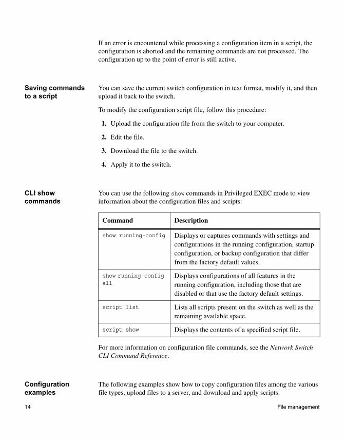
CLI show commands
You can use the following show commands in Privileged EXEC mode to view information about the configuration files and scripts:
For more information on configuration file commands, see the Network Switch CLI Command Reference.
Configuration examples
The following examples show how to copy configuration files among the various file types, upload files to a server, and download and apply scripts.
Command Description
show running-config Displays or captures commands with settings and configurations in the running configuration, startup configuration, or backup configuration that differ from the factory default values.
show running-config all
Displays configurations of all features in the running configuration, including those that are disabled or that use the factory default settings.
script list Lists all scripts present on the switch as well as the remaining available space.
script show Displays the contents of a specified script file.
14 File management
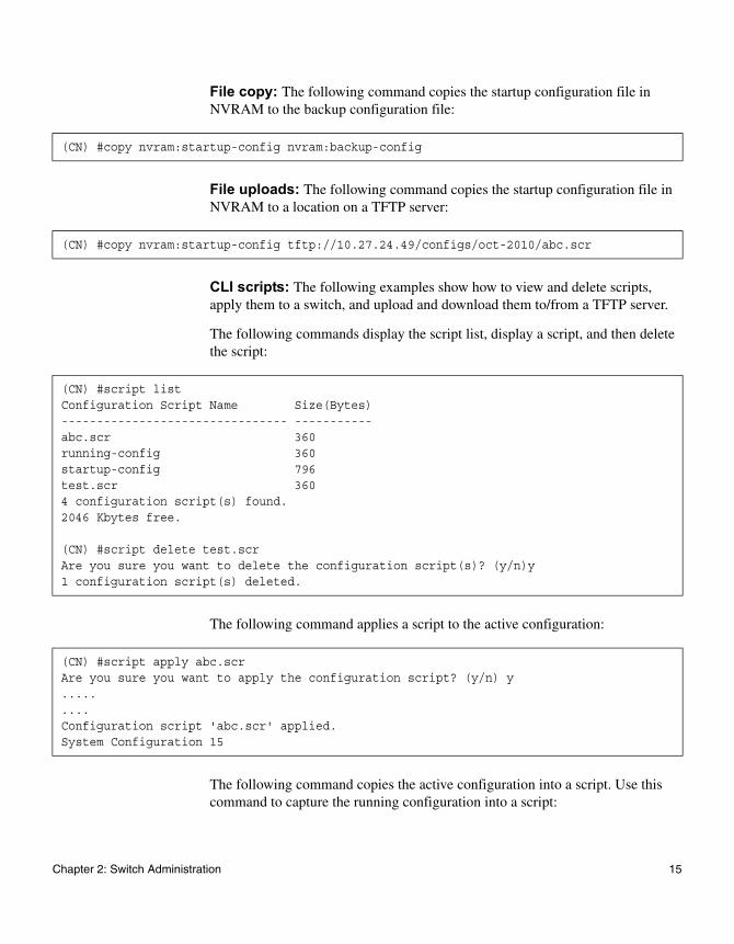
File copy: The following command copies the startup configuration file in NVRAM to the backup configuration file:
File uploads: The following command copies the startup configuration file in NVRAM to a location on a TFTP server:
CLI scripts: The following examples show how to view and delete scripts, apply them to a switch, and upload and download them to/from a TFTP server.
The following commands display the script list, display a script, and then delete the script:
The following command applies a script to the active configuration:
The following command copies the active configuration into a script. Use this command to capture the running configuration into a script:
(CN) #copy nvram:startup-config nvram:backup-config
(CN) #copy nvram:startup-config tftp://10.27.24.49/configs/oct-2010/abc.scr
(CN) #script listConfiguration Script Name Size(Bytes)-------------------------------- -----------abc.scr 360running-config 360startup-config 796test.scr 3604 configuration script(s) found.2046 Kbytes free.
(CN) #script delete test.scrAre you sure you want to delete the configuration script(s)? (y/n)y1 configuration script(s) deleted.
(CN) #script apply abc.scrAre you sure you want to apply the configuration script? (y/n) y.........Configuration script 'abc.scr' applied.System Configuration 15
Chapter 2: Switch Administration 15

The following command uploads a configuration script to a TFTP server:
The following command downloads a configuration script from the TFTP server to the switch:
The following example validates a script:
(CN) #show running-config running-config.scrConfig script created successfully.
(CN) #copy nvram:script abc.scr tftp://10.27.64.141/abc.scrMode........................................... TFTPSet TFTP Server IP............................. 10.27.64.141TFTP Path...................................... ./TFTP Filename.................................. abc.scrData Type...................................... Config ScriptSource Filename................................ abc.scrManagement access will be blocked for the duration of the transferAre you sure you want to start? (y/n) y267 bytes transferredFile transfer operation completed successfully.
(CN) #copy tftp://10.27.64.141/abc.scr nvram:script abc.scrMode........................................... TFTPSet TFTP Server IP............................. 10.27.64.141TFTP Path...................................... ./TFTP Filename.................................. abc.scrData Type...................................... Config ScriptDestination Filename........................... abc.scrManagement access will be blocked for the duration of the transferAre you sure you want to start? (y/n) y193 bytes transferredValidating configuration script...configure16 System Configurationexitconfigurelogging web-sessionbridge aging-time 100exitConfiguration script validated.File transfer operation completed successfully.
16 File management
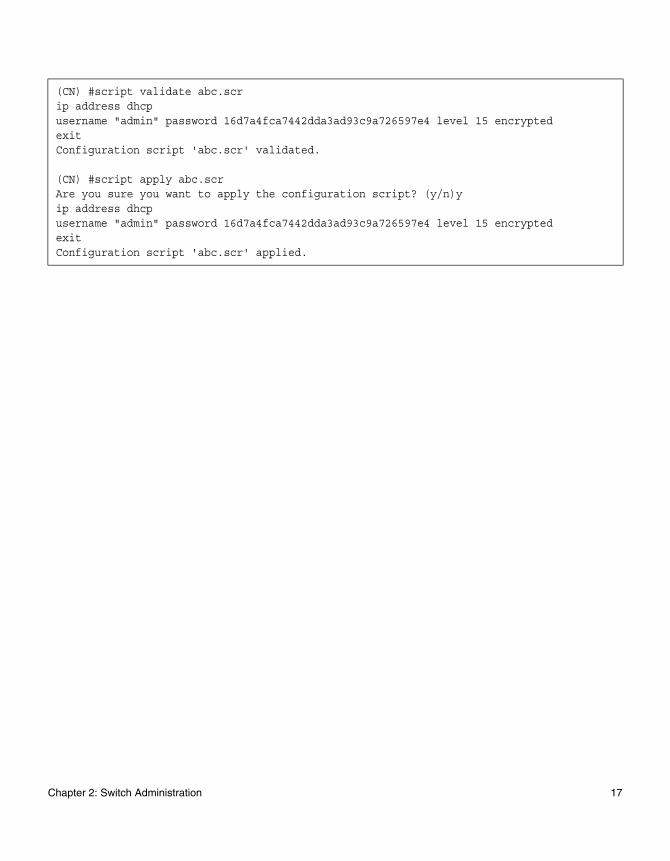
(CN) #script validate abc.scrip address dhcpusername "admin" password 16d7a4fca7442dda3ad93c9a726597e4 level 15 encryptedexitConfiguration script 'abc.scr' validated.
(CN) #script apply abc.scrAre you sure you want to apply the configuration script? (y/n)yip address dhcpusername "admin" password 16d7a4fca7442dda3ad93c9a726597e4 level 15 encryptedexitConfiguration script 'abc.scr' applied.
Chapter 2: Switch Administration 17
File managementFile uploads and downloads
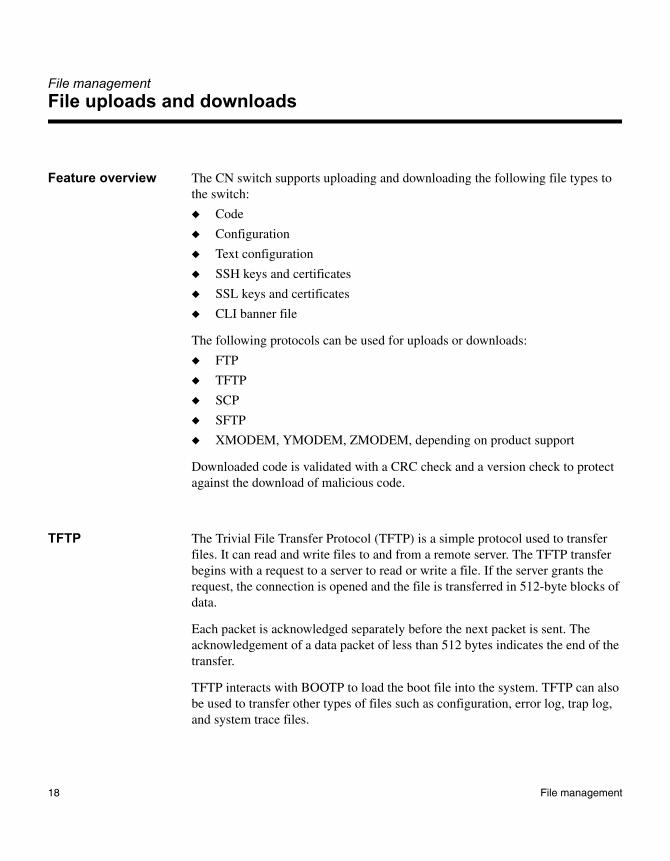
Feature overview The CN switch supports uploading and downloading the following file types to the switch:
◆ Code
◆ Configuration
◆ Text configuration
◆ SSH keys and certificates
◆ SSL keys and certificates
◆ CLI banner file
The following protocols can be used for uploads or downloads:
◆ FTP
◆ TFTP
◆ SCP
◆ SFTP
◆ XMODEM, YMODEM, ZMODEM, depending on product support
Downloaded code is validated with a CRC check and a version check to protect against the download of malicious code.
TFTP The Trivial File Transfer Protocol (TFTP) is a simple protocol used to transfer files. It can read and write files to and from a remote server. The TFTP transfer begins with a request to a server to read or write a file. If the server grants the request, the connection is opened and the file is transferred in 512-byte blocks of data.
Each packet is acknowledged separately before the next packet is sent. The acknowledgement of a data packet of less than 512 bytes indicates the end of the transfer.
TFTP interacts with BOOTP to load the boot file into the system. TFTP can also be used to transfer other types of files such as configuration, error log, trap log, and system trace files.
18 File management
SCP and SFTP The CN switch supports Secure Copy (SCP) and Secure FTP (SFTP) as secure methods of file transfer.
XMODEM, YMODEM, ZMODEM
The CN switch supports using the XMODEM, YMODEM, or ZMODEM protocols (depending on product support) to transfer operational code, configuration files, and logs over the serial port. The switch supports both the XMODEM standard mode and the XMODEM-1K mode.
Telnet and SNMP session limits
Up to four inbound Telnet/SSH sessions are allowed. Each CLI session can have up to one outbound Telnet session. This allows for a maximum of five concurrent outbound Telnet sessions: one for each inbound Telnet session and one outbound Telnet session from the serial interface. There are no software-imposed restrictions on the number of SNMP operations. Configuration changes made using SNMP are processed on a first come, first serve basis.
For more information on the file upload and download commands, see the Network Switch CLI Command Reference.
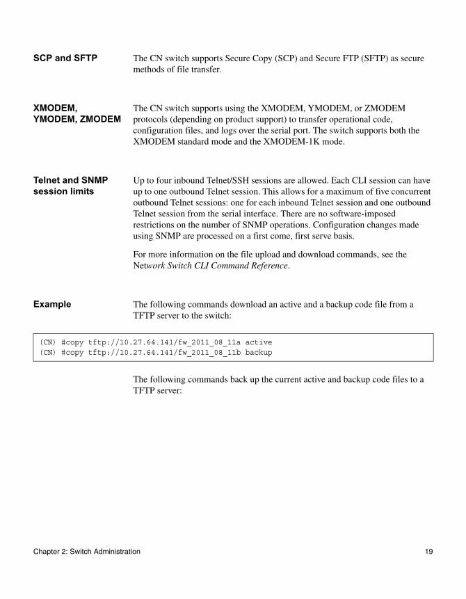
Example The following commands download an active and a backup code file from a TFTP server to the switch:
The following commands back up the current active and backup code files to a TFTP server:
(CN) #copy tftp://10.27.64.141/fw_2011_08_11a active(CN) #copy tftp://10.27.64.141/fw_2011_08_11b backup
Chapter 2: Switch Administration 19
File managementDual image support
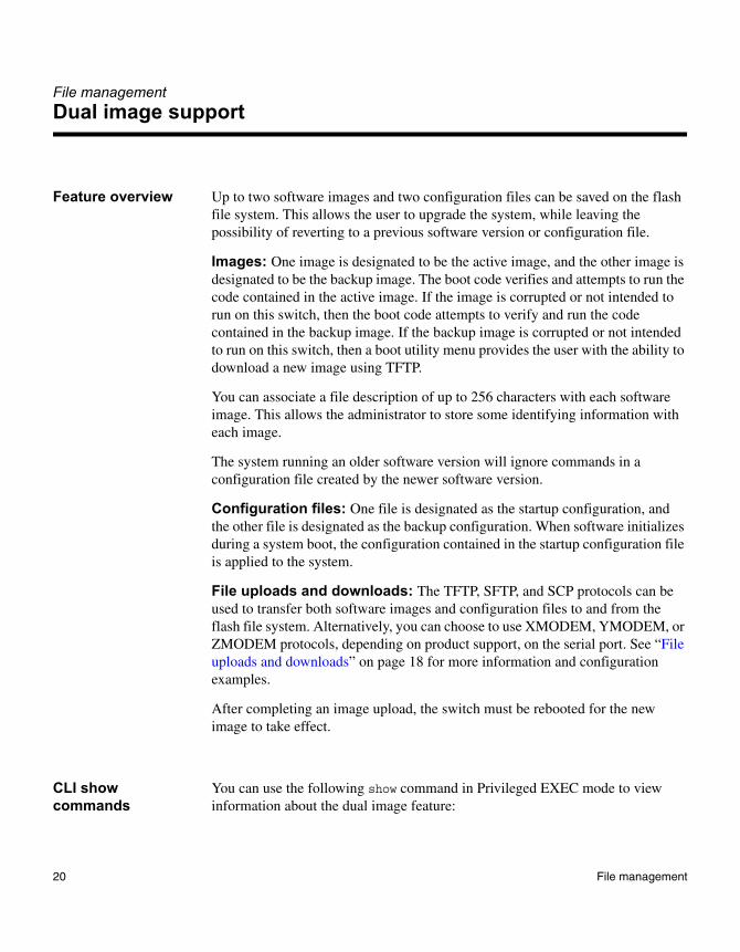
Feature overview Up to two software images and two configuration files can be saved on the flash file system. This allows the user to upgrade the system, while leaving the possibility of reverting to a previous software version or configuration file.
Images: One image is designated to be the active image, and the other image is designated to be the backup image. The boot code verifies and attempts to run the code contained in the active image. If the image is corrupted or not intended to run on this switch, then the boot code attempts to verify and run the code contained in the backup image. If the backup image is corrupted or not intended to run on this switch, then a boot utility menu provides the user with the ability to download a new image using TFTP.
You can associate a file description of up to 256 characters with each software image. This allows the administrator to store some identifying information with each image.
The system running an older software version will ignore commands in a configuration file created by the newer software version.
Configuration files: One file is designated as the startup configuration, and the other file is designated as the backup configuration. When software initializes during a system boot, the configuration contained in the startup configuration file is applied to the system.
File uploads and downloads: The TFTP, SFTP, and SCP protocols can be used to transfer both software images and configuration files to and from the flash file system. Alternatively, you can choose to use XMODEM, YMODEM, or ZMODEM protocols, depending on product support, on the serial port. See “File uploads and downloads” on page 18 for more information and configuration examples.
After completing an image upload, the switch must be rebooted for the new image to take effect.
CLI show commands
You can use the following show command in Privileged EXEC mode to view information about the dual image feature:
20 File management
For more information on the commands to configure the dual image feature, see the Network Switch CLI Command Reference.
Configuration example
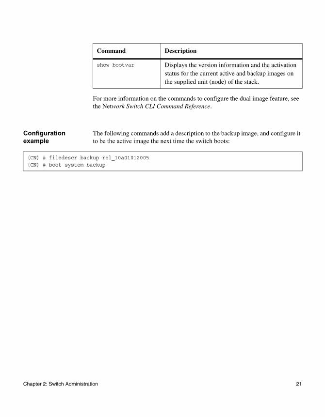
The following commands add a description to the backup image, and configure it to be the active image the next time the switch boots:
Command Description
show bootvar Displays the version information and the activation status for the current active and backup images on the supplied unit (node) of the stack.
(CN) # filedescr backup rel_10a01012005(CN) # boot system backup
Chapter 2: Switch Administration 21
SNMP
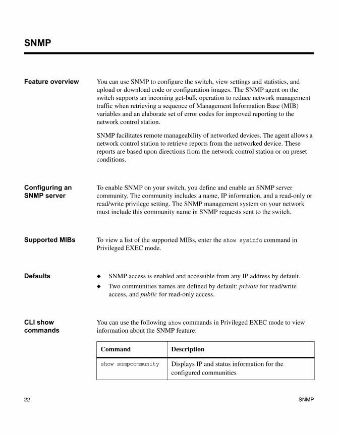
Feature overview You can use SNMP to configure the switch, view settings and statistics, and upload or download code or configuration images. The SNMP agent on the switch supports an incoming get-bulk operation to reduce network management traffic when retrieving a sequence of Management Information Base (MIB) variables and an elaborate set of error codes for improved reporting to the network control station.
SNMP facilitates remote manageability of networked devices. The agent allows a network control station to retrieve reports from the networked device. These reports are based upon directions from the network control station or on preset conditions.
Configuring an SNMP server
To enable SNMP on your switch, you define and enable an SNMP server community. The community includes a name, IP information, and a read-only or read/write privilege setting. The SNMP management system on your network must include this community name in SNMP requests sent to the switch.
Supported MIBs To view a list of the supported MIBs, enter the show sysinfo command in Privileged EXEC mode.
Defaults ◆ SNMP access is enabled and accessible from any IP address by default.
◆ Two communities names are defined by default: private for read/write access, and public for read-only access.
CLI show commands
You can use the following show commands in Privileged EXEC mode to view information about the SNMP feature:
Command Description
show snmpcommunity Displays IP and status information for the configured communities
22 SNMP
For more information on SNMP commands, see the Network Switch CLI Command Reference.
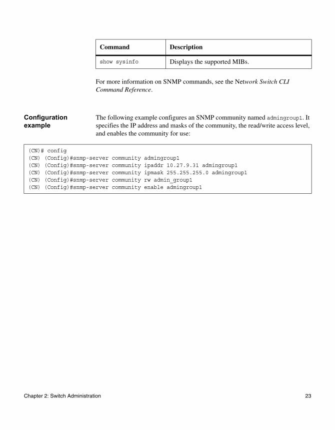
Configuration example
The following example configures an SNMP community named admingroup1. It specifies the IP address and masks of the community, the read/write access level, and enables the community for use:
show sysinfo Displays the supported MIBs.
Command Description
(CN)# config(CN) (Config)#snmp-server community admingroup1(CN) (Config)#snmp-server community ipaddr 10.27.9.31 admingroup1(CN) (Config)#snmp-server community ipmask 255.255.255.0 admingroup1(CN) (Config)#snmp-server community rw admin_group1(CN) (Config)#snmp-server community enable admingroup1
Chapter 2: Switch Administration 23
User management
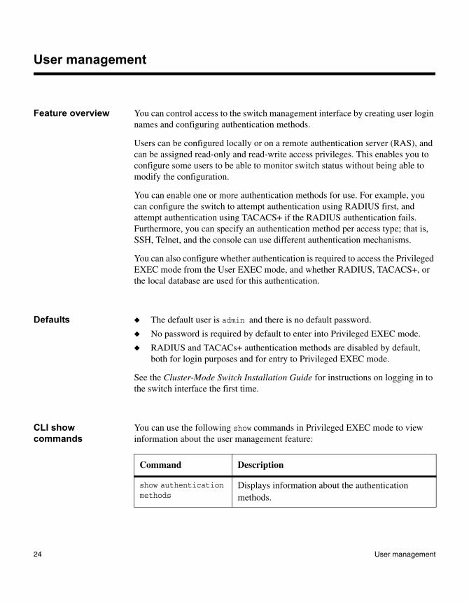
Feature overview You can control access to the switch management interface by creating user login names and configuring authentication methods.
Users can be configured locally or on a remote authentication server (RAS), and can be assigned read-only and read-write access privileges. This enables you to configure some users to be able to monitor switch status without being able to modify the configuration.
You can enable one or more authentication methods for use. For example, you can configure the switch to attempt authentication using RADIUS first, and attempt authentication using TACACS+ if the RADIUS authentication fails. Furthermore, you can specify an authentication method per access type; that is, SSH, Telnet, and the console can use different authentication mechanisms.
You can also configure whether authentication is required to access the Privileged EXEC mode from the User EXEC mode, and whether RADIUS, TACACS+, or the local database are used for this authentication.
Defaults ◆ The default user is admin and there is no default password.
◆ No password is required by default to enter into Privileged EXEC mode.
◆ RADIUS and TACACs+ authentication methods are disabled by default, both for login purposes and for entry to Privileged EXEC mode.
See the Cluster-Mode Switch Installation Guide for instructions on logging in to the switch interface the first time.
CLI show commands
You can use the following show commands in Privileged EXEC mode to view information about the user management feature:
Command Description
show authentication methods
Displays information about the authentication methods.
24 User management
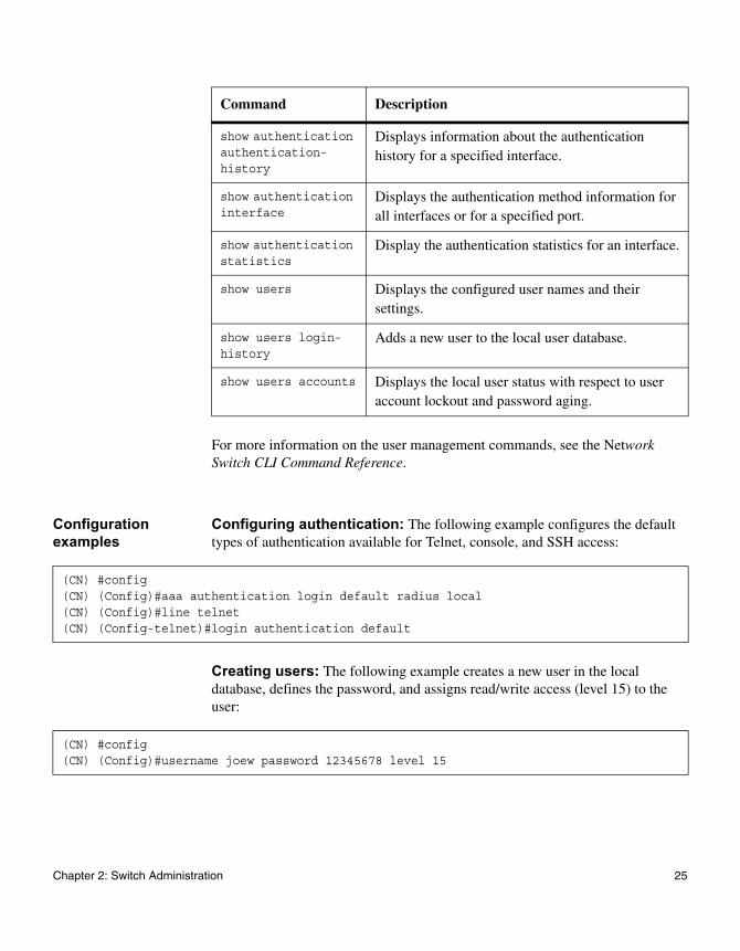
For more information on the user management commands, see the Network Switch CLI Command Reference.
Configuration examples
Configuring authentication: The following example configures the default types of authentication available for Telnet, console, and SSH access:
Creating users: The following example creates a new user in the local database, defines the password, and assigns read/write access (level 15) to the user:
show authentication authentication-history
Displays information about the authentication history for a specified interface.
show authentication interface
Displays the authentication method information for all interfaces or for a specified port.
show authentication statistics
Display the authentication statistics for an interface.
show users Displays the configured user names and their settings.
show users login-history
Adds a new user to the local user database.
show users accounts Displays the local user status with respect to user account lockout and password aging.
Command Description
(CN) #config(CN) (Config)#aaa authentication login default radius local(CN) (Config)#line telnet(CN) (Config-telnet)#login authentication default
(CN) #config(CN) (Config)#username joew password 12345678 level 15
Chapter 2: Switch Administration 25

Changing the admin password: The following example changes the admin password.
(CN) #config(CN) (Config)#(CN1610)>passwordEnter old password:********Enter new password:********Confirm new password:********
26 User management
Logs and Syslog
Feature overview The CN switch FASTPATH software components generate messages that you can use to understand the state of the system, and to diagnose issues that arise during operation. Messages are generated in response to events, faults, or errors occurring on the platform, and by configuration changes or other occurrences. These messages are stored locally on the platform and can be forwarded to one or more centralized points of collection for monitoring or long-term archival. You can configure filters for the messages, whereby they are logged or forwarded based on their severity level and the generating component.
Log types The switch keeps the following types of logs:
In-Memory Log: This log stores messages in memory based on the settings for the component that generated the message and the severity level of the message. On stackable systems, this log exists only on the top-of-stack platform. Other platforms in the stack forward their messages to the top of stack log. Access to in-memory logs on other than the top-of-stack platform is not supported.
Local Persistent Log: This log is stored in persistent storage. Persistent storage survives across platform reboots and is usually in flash, EEPROM, or battery-backed RAM. On platforms that have some means of supporting persistent storage, two types of persistent logs can be configured:
◆ System startup log: This log stores the first messages received after a system reboot, up to 32 messages. When the capacity is reached, no new log messages are accepted.
◆ System operation log: This log stores the last messages received during system operation, up to 1000 messages. When the capacity is reached, the older message are removed to make room for new messages.
Log criteria A message that meets the storage criteria is stored in either the system startup log or the system operation log, but not both. In other words, on system startup, if the startup log is configured, then it stores messages up to its limit. When the startup log is full, the operation log, if configured, begins to store the messages.
Chapter 2: Switch Administration 27
By default, only messages that are of severity ALERT or EMERGENCY are stored in the persistent log. Because these messages are of high value, persistent messages are logged immediately into the persistent log. The administrator has the option of configuring the persistent log to store lower severity messages as well.
Log versions The system keeps up to three versions of the persistent logs. Each of these historical logs represents the system state immediately after or immediately prior to the previous n reboots, respectively. The log files are named <file>1.txt, <file>2.txt, and <file>3.txt where the number immediately prior to the period in the file name indicates the version of the file. For example, on system startup, <file>3.txt is deleted, <file>2.txt is renamed to <file>3.txt, <file>1.txt is renamed to <file>2.txt, <file>1.txt is created, and logging begins into <file>1.txt. The <file> string in the previous example is replaced by the string olog for the operation log and slog for the startup log.
Log access You can view the buffered and persistent log contents by using the CLI show logging command.
You can also use XMODEM over the serial port or TFTP, SFTP, or SCP over a Telnet or SSH connection to retrieve the log files for viewing in a text editor on your system. You can use the CLI command copy nvram:log to initiate a file transfer.
Log format and attributes
The format of the persistent log consists of fixed format records with a fixed maximum length of 204 bytes. Each record consists of ASCII characters and is terminated by an ASCII NULL. Records always begin at a multiple of 204 bytes. Once the file has been created, it is never erased. Older records are overwritten in the operation log file. The formula for the offset of the next record to write in the operation file is:
((number of records written to both the startup and operation files minus 32) modulo 1000) times 204.
Log message attributes include:
◆ Message ID—Each message includes a numeric ID that distinguishes it from all other messages generated since the last reboot. The IDs begin at 1 and increment by 1 for each message generated. They restart at 1 when the stack boots, or when a switchover of the Master Unit occurs.
28 Logs and Syslog
◆ Severity—Each message identifies the severity of the causal event. Severity is specified as one of the following:
Emergency (0): system is unusable.
Alert (1): action must be taken immediately.
Critical (2): critical conditions.
Error (3): error conditions.
Warning (4): warning conditions.
Notice(5): normal but significant conditions.
Informational(6): informational messages.
Debug(7): debug-level messages.
◆ Timestamp—Each message is time-stamped with the local time or, if the platform is not synchronized, the elapsed time since last reboot.
◆ Host Name—the name of the host logging the information. In a stack, each switch must have a different host name.
◆ Component ID—Each message identifies the software component that generated the message, if known.
◆ Process/thread ID—Each message identifies the process or thread ID of the processor thread that called the log API.
◆ File name—Each message identifies the file containing the code from which the causal event was generated.
◆ Line number—Each message identifies the line number of the file identified above from which the causal event was generated.
◆ Additional Information—Each message can optionally contain additional information considered useful to the network operator.
Example log message
The following is a sample log message:
<17>Aug 24 05:34:05 2004 STK0 MSTP[2110]: mspt_api.c(318) 237 %% Interface 12 transitioned to root state on message age timer expiry
This example indicates a user-level message (1) with severity 7 (debug) on a stand-alone system (not stacked). It was generated by the MSTP component running in thread ID 2110 on Aug 24 05:34:05 2004 by line 318 of file
mstp_api.c. This is the 237th message logged. Messages logged to a collector or relayed by syslog have an identical format to this message. Note that the timestamp is only valid if the system is running SNTP. Otherwise, the timestamp starts at Jan 01 00:00:00 1970.
Chapter 2: Switch Administration 29
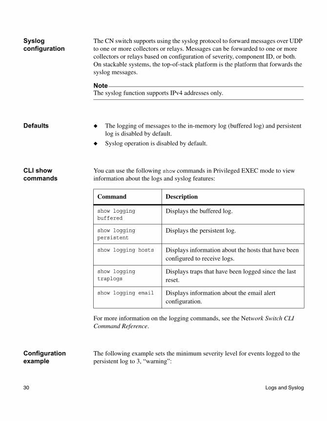
Syslog configuration
The CN switch supports using the syslog protocol to forward messages over UDP to one or more collectors or relays. Messages can be forwarded to one or more collectors or relays based on configuration of severity, component ID, or both. On stackable systems, the top-of-stack platform is the platform that forwards the syslog messages.
NoteThe syslog function supports IPv4 addresses only.
Defaults ◆ The logging of messages to the in-memory log (buffered log) and persistent log is disabled by default.
◆ Syslog operation is disabled by default.
CLI show commands
You can use the following show commands in Privileged EXEC mode to view information about the logs and syslog features:
For more information on the logging commands, see the Network Switch CLI Command Reference.
Configuration example
The following example sets the minimum severity level for events logged to the persistent log to 3, “warning”:
Command Description
show logging buffered
Displays the buffered log.
show logging persistent
Displays the persistent log.
show logging hosts Displays information about the hosts that have been configured to receive logs.
show logging traplogs
Displays traps that have been logged since the last reset.
show logging email Displays information about the email alert configuration.
30 Logs and Syslog

(CN) #config(CN) (Config)#logging persistent 3
Chapter 2: Switch Administration 31
SNTP and clock settings
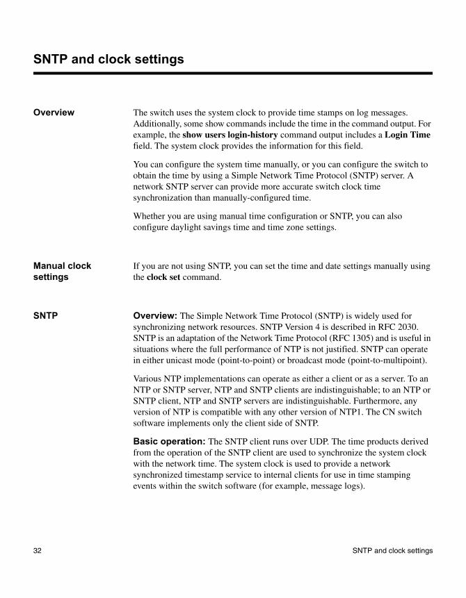
Overview The switch uses the system clock to provide time stamps on log messages. Additionally, some show commands include the time in the command output. For example, the show users login-history command output includes a Login Time field. The system clock provides the information for this field.
You can configure the system time manually, or you can configure the switch to obtain the time by using a Simple Network Time Protocol (SNTP) server. A network SNTP server can provide more accurate switch clock time synchronization than manually-configured time.
Whether you are using manual time configuration or SNTP, you can also configure daylight savings time and time zone settings.
Manual clock settings
If you are not using SNTP, you can set the time and date settings manually using the clock set command.
SNTP Overview: The Simple Network Time Protocol (SNTP) is widely used for synchronizing network resources. SNTP Version 4 is described in RFC 2030. SNTP is an adaptation of the Network Time Protocol (RFC 1305) and is useful in situations where the full performance of NTP is not justified. SNTP can operate in either unicast mode (point-to-point) or broadcast mode (point-to-multipoint).
Various NTP implementations can operate as either a client or as a server. To an NTP or SNTP server, NTP and SNTP clients are indistinguishable; to an NTP or SNTP client, NTP and SNTP servers are indistinguishable. Furthermore, any version of NTP is compatible with any other version of NTP1. The CN switch software implements only the client side of SNTP.
Basic operation: The SNTP client runs over UDP. The time products derived from the operation of the SNTP client are used to synchronize the system clock with the network time. The system clock is used to provide a network synchronized timestamp service to internal clients for use in time stamping events within the switch software (for example, message logs).
32 SNTP and clock settings
In the event that the SNTP client is unable to synchronize with the network clock or is disabled, the internal clients will continue to use the system clock for timestamps. In general, internal clients will not be aware of whether the timestamps are synchronized with the network clock.
Depending on the mode of operation, the SNTP client listens on UDP port 123 on the local management interface for broadcast UDP packets containing valid NTP data or queries one or more configured time servers and listens for responses.
The switch internal clients include the message logging subsystem, the trap manager (timestamps for traps), and other clients that require high-precision synchronized timestamps.
Configuration options: The administrator has the option of enabling a security mechanism to ensure that only authorized servers are allowed to distribute time to the client. The user defines a key on the switch and enables authentication. The same key must be defined on the server in order for the switch to accept time information from that server.
The administrator can configure a physical or logical switch interface as a client source interface, which is then used for all SNTP communications between the SNTP client and server. The IP address of the designated source interface is used in the IP header of SNTP management protocol packets. This allows security devices, such as firewalls, to identify all source packets coming from a specific device. The loopback IP address or VLAN can also be specified as the source address or, if no SNTP source interface is specified, the IP address of the originating interface is used.
IPv6 support: Support for IPv6 address configuration is provided to the existing SNTP client. The end user can configure either an IPv4 or IPv6 address or a host name for an SNTP server among the list of servers. In unicast mode, one of the servers from the list is selected as the active server to be used for polling based on priority and configured order. The servers are treated alike, independent of IPv4 or IPv6 or host name address formats. At any given point of time, the client operates in unicast or broadcast mode. In broadcast mode, the SNTP client listens for server packets from IPv4 and IPv6 networks at the same time on port number 123. On IPv6 networks, the SNTP client listens to the link-local scoped IANA multicast address ff02::101 (reserved for SNTP) for server packets. The client logic to handle packet contents does not change with support for IPv6 networks.
Chapter 2: Switch Administration 33
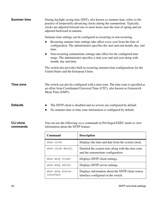
Summer time During daylight saving time (DST), also known as summer time, refers to the practice of temporarily advancing clocks during the summertime. Typically, clocks are adjusted forward one or more hours near the start of spring and are adjusted backward in autumn.
Summer time settings can be configured as recurring or non-recurring.
◆ Recurring summer time settings take effect every year from the time of configuration. The administrator specifies the start and end month, day, and time.
◆ Non-recurring summertime settings take effect for the configured time range. The administrator specifies a start year and end year along with month, day and time.
The switch also provides built-in recurring summer-time configurations for the United States and the European Union.
Time zone The switch can also be configured with a time zone. The time zone is specified as an offset from Coordinated Universal Time (UTC), also known as Greenwich Mean Time (GMT).
Defaults ◆ The SNTP client is disabled and no servers are configured by default.
◆ No summer time or time zone information is configured by default.
CLI show commands
You can use the following show commands in Privileged EXEC mode to view information about the SNTP feature:
Command Description
show clock Displays the time and date from the system clock.
show clock detail Detailed the system time along with the time zone and the summertime configuration.
show sntp client Displays SNTP client settings.
show sntp server Displays SNTP server settings.
show sntp source-interface
Displays information about the SNTP client source interface configured on the switch.
34 SNTP and clock settings
For more information on the SNTP commands, see the Network Switch CLI Command Reference.
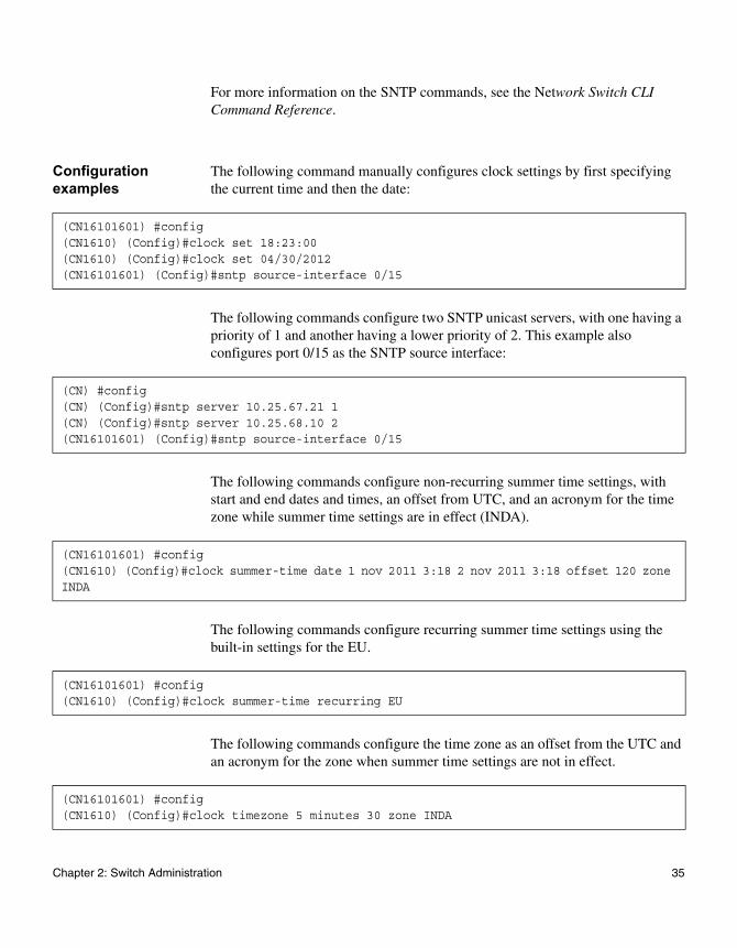
Configuration examples
The following command manually configures clock settings by first specifying the current time and then the date:
The following commands configure two SNTP unicast servers, with one having a priority of 1 and another having a lower priority of 2. This example also configures port 0/15 as the SNTP source interface:
The following commands configure non-recurring summer time settings, with start and end dates and times, an offset from UTC, and an acronym for the time zone while summer time settings are in effect (INDA).
The following commands configure recurring summer time settings using the built-in settings for the EU.
The following commands configure the time zone as an offset from the UTC and an acronym for the zone when summer time settings are not in effect.
(CN16101601) #config(CN1610) (Config)#clock set 18:23:00(CN1610) (Config)#clock set 04/30/2012(CN16101601) (Config)#sntp source-interface 0/15
(CN) #config(CN) (Config)#sntp server 10.25.67.21 1(CN) (Config)#sntp server 10.25.68.10 2(CN16101601) (Config)#sntp source-interface 0/15
(CN16101601) #config(CN1610) (Config)#clock summer-time date 1 nov 2011 3:18 2 nov 2011 3:18 offset 120 zone INDA
(CN16101601) #config(CN1610) (Config)#clock summer-time recurring EU
(CN16101601) #config(CN1610) (Config)#clock timezone 5 minutes 30 zone INDA
Chapter 2: Switch Administration 35
DNS client
Feature overview The Domain Name System (DNS) is an Internet directory service. A DNS server translates host names into IP addresses. When enabled, the DNS client provides a host-name lookup services to other software components. The DNS client service can be globally enabled or disabled.
A DNS client is often referred to as a resolver. A DNS client uses the DNS protocol to obtain resource data from name servers on its network. A DNS client obtains the resource data from name servers as a response to its requests. Resolvers must be able to access a minimum of one name server and use that name server's information to answer a query directly, or pursue the query using referrals to other name servers.
Operation The DNS client contacts one or more configured DNS servers to resolve a host name to an IP address. The list of servers is configured by providing an IP address for each DNS server. When more than one DNS server is configured in the system, server precedence is determined by the order in which the servers are added.
The DNS client in the switches operates in recursive mode, which means that the DNS client communicates directly only with the configured DNS server. If the DNS server does not itself know a host name presented in a query, then the server contacts other name servers for host-name resolution on behalf of the client. The configured DNS server returns the response to the client rather than referring the client to another server for name resolution.
Configuration options
The CN switch supports IPv4 DNS servers. The server address can be configured statically (by you) or learned dynamically by the DHCP client.
A default domain name can be configured, which defines the domain to use when performing a lookup on an unqualified host name.
You can configure a default domain-name list. If there is no domain list, the default domain name configured is used. If there is a domain list, the default domain name is not used. An entry in domain-name list can be configured statically (by you) or learned dynamically by the DHCP client.
36 DNS client
You can configure a default domain name, which defines the domain to use when performing a lookup on an unqualified host name. You can also configure a domain-name list. If there is no domain list, the default domain name is used. If there is a domain-name list, the default domain name is not used. An entry in domain-name list can be configured statically (by you) or learned dynamically by the DHCP client. As with DNS server addresses, because the switch has no DHCPv6 client, IPv6 entries cannot be learned dynamically.
Static host name-to-IPv4 or -IPv6 address mappings can be added and removed from the local cache. When a conflict exists between a static and dynamic mapping, the static mapping takes precedence.
You can also specify the physical or logical interface to use as the DNS client source interface. If configured, the address of source Interface is used for all DNS communications between the DNS server and the DNS client. Alternatively, you can specify the loopback interface or a VLAN ID to serve as the source address.
The DNS client supports host names with single spaces embedded within the name, but consecutive spaces are not supported. Underscores are accepted in host names as well.
Defaults The DNS client is enabled by default. No default IP host mappings, default domain names, or name servers are configured.
CLI show commands
You can use the following show command in User EXEC mode to view information about the features of DNS:
For more information on the DNS commands, see the Network Switch CLI Command Reference.
Command Description
show hosts Displays the default domain name, a list of name server hosts, and the static and the cached list of host names and addresses.
Chapter 2: Switch Administration 37
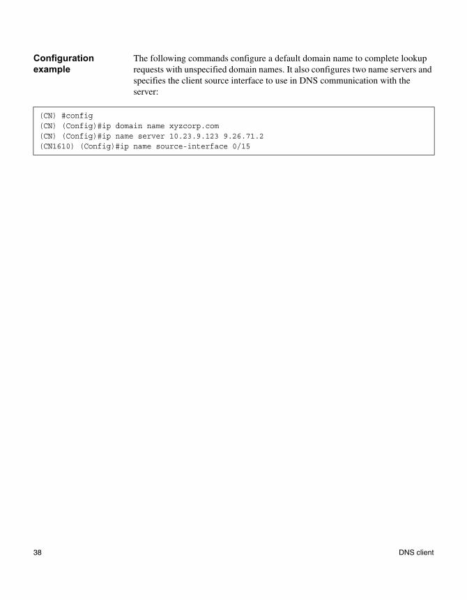
Configuration example
The following commands configure a default domain name to complete lookup requests with unspecified domain names. It also configures two name servers and specifies the client source interface to use in DNS communication with the server:
(CN) #config(CN) (Config)#ip domain name xyzcorp.com(CN) (Config)#ip name server 10.23.9.123 9.26.71.2(CN1610) (Config)#ip name source-interface 0/15
38 DNS client
Environmental status
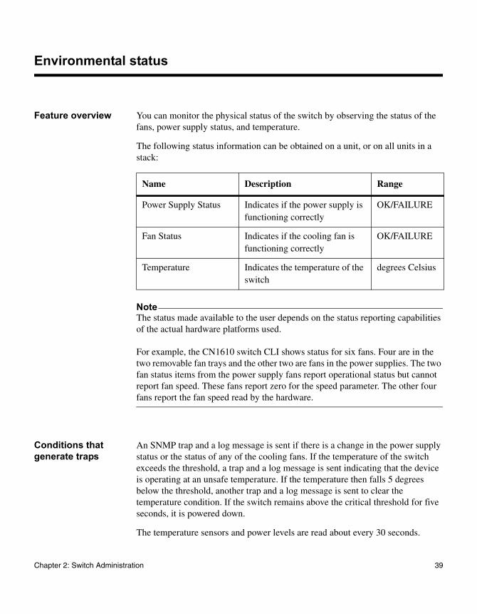
Feature overview You can monitor the physical status of the switch by observing the status of the fans, power supply status, and temperature.
The following status information can be obtained on a unit, or on all units in a stack:
NoteThe status made available to the user depends on the status reporting capabilities of the actual hardware platforms used.
For example, the CN1610 switch CLI shows status for six fans. Four are in the two removable fan trays and the other two are fans in the power supplies. The two fan status items from the power supply fans report operational status but cannot report fan speed. These fans report zero for the speed parameter. The other four fans report the fan speed read by the hardware.
Conditions that generate traps
An SNMP trap and a log message is sent if there is a change in the power supply status or the status of any of the cooling fans. If the temperature of the switch exceeds the threshold, a trap and a log message is sent indicating that the device is operating at an unsafe temperature. If the temperature then falls 5 degrees below the threshold, another trap and a log message is sent to clear the temperature condition. If the switch remains above the critical threshold for five seconds, it is powered down.
The temperature sensors and power levels are read about every 30 seconds.
Name Description Range
Power Supply Status Indicates if the power supply is functioning correctly
OK/FAILURE
Fan Status Indicates if the cooling fan is functioning correctly
OK/FAILURE
Temperature Indicates the temperature of the switch
degrees Celsius
Chapter 2: Switch Administration 39

CLI show commands
You can use the following show command in Privileged EXEC mode to view information about the environmental status feature:
Command Description
show environment Displays environmental status information.
40 Environmental status
Outbound Telnet
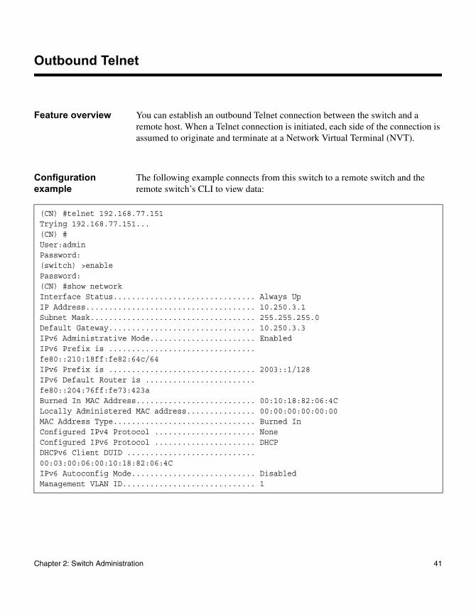
Feature overview You can establish an outbound Telnet connection between the switch and a remote host. When a Telnet connection is initiated, each side of the connection is assumed to originate and terminate at a Network Virtual Terminal (NVT).
Configuration example
The following example connects from this switch to a remote switch and the remote switch’s CLI to view data:
(CN) #telnet 192.168.77.151Trying 192.168.77.151...(CN) #User:adminPassword:(switch) >enablePassword:(CN) #show networkInterface Status............................... Always UpIP Address..................................... 10.250.3.1Subnet Mask.................................... 255.255.255.0Default Gateway................................ 10.250.3.3IPv6 Administrative Mode....................... EnabledIPv6 Prefix is ................................fe80::210:18ff:fe82:64c/64IPv6 Prefix is ................................ 2003::1/128IPv6 Default Router is ........................fe80::204:76ff:fe73:423aBurned In MAC Address.......................... 00:10:18:82:06:4CLocally Administered MAC address............... 00:00:00:00:00:00MAC Address Type............................... Burned InConfigured IPv4 Protocol ...................... NoneConfigured IPv6 Protocol ...................... DHCPDHCPv6 Client DUID ............................00:03:00:06:00:10:18:82:06:4CIPv6 Autoconfig Mode........................... DisabledManagement VLAN ID............................. 1
Chapter 2: Switch Administration 41

42 Outbound Telnet
Chapter 3: Ports and LAGs
3
Ports and LAGsAbout this chapter This chapter describes how to configure and view status information about system ports and link aggregation groups (LAGs).
Topics in this chapter
This chapter includes the following topics:
◆ “Port configuration” on page 44
◆ “SFP/SFP+ ports” on page 47
◆ “Link aggregation” on page 48
43
Port configuration
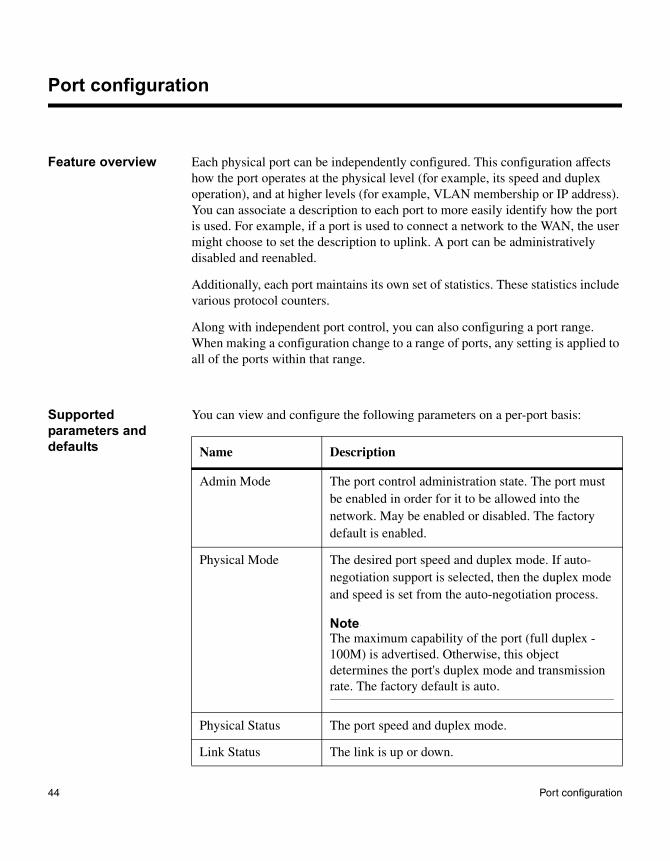
Feature overview Each physical port can be independently configured. This configuration affects how the port operates at the physical level (for example, its speed and duplex operation), and at higher levels (for example, VLAN membership or IP address). You can associate a description to each port to more easily identify how the port is used. For example, if a port is used to connect a network to the WAN, the user might choose to set the description to uplink. A port can be administratively disabled and reenabled.
Additionally, each port maintains its own set of statistics. These statistics include various protocol counters.
Along with independent port control, you can also configuring a port range. When making a configuration change to a range of ports, any setting is applied to all of the ports within that range.
Supported parameters and defaults
You can view and configure the following parameters on a per-port basis:
Name Description
Admin Mode The port control administration state. The port must be enabled in order for it to be allowed into the network. May be enabled or disabled. The factory default is enabled.
Physical Mode The desired port speed and duplex mode. If auto-negotiation support is selected, then the duplex mode and speed is set from the auto-negotiation process.
NoteThe maximum capability of the port (full duplex -100M) is advertised. Otherwise, this object determines the port's duplex mode and transmission rate. The factory default is auto.
Physical Status The port speed and duplex mode.
Link Status The link is up or down.
44 Port configuration
For more information on the port configuration commands, see the CN1610 Network Switch CLI Command Reference.
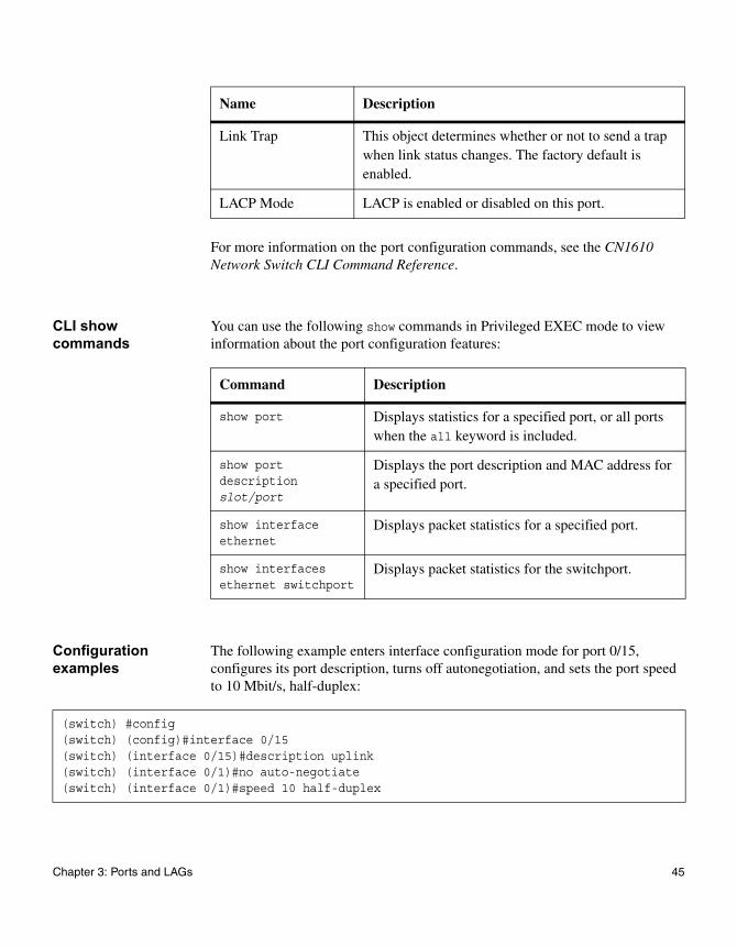
CLI show commands
You can use the following show commands in Privileged EXEC mode to view information about the port configuration features:
Configuration examples
The following example enters interface configuration mode for port 0/15, configures its port description, turns off autonegotiation, and sets the port speed to 10 Mbit/s, half-duplex:
Link Trap This object determines whether or not to send a trap when link status changes. The factory default is enabled.
LACP Mode LACP is enabled or disabled on this port.
Name Description
Command Description
show port Displays statistics for a specified port, or all ports when the all keyword is included.
show port description slot/port
Displays the port description and MAC address for a specified port.
show interface ethernet
Displays packet statistics for a specified port.
show interfaces ethernet switchport
Displays packet statistics for the switchport.
(switch) #config(switch) (config)#interface 0/15(switch) (interface 0/15)#description uplink(switch) (interface 0/1)#no auto-negotiate(switch) (interface 0/1)#speed 10 half-duplex
Chapter 3: Ports and LAGs 45

Autonegotiation can be enabled globally on the switch or on a per-port basis. The following example configures the port to autonegotiate its settings:
(CN1610) #configure(CN1610) #interface 0/1(CN1610) (Interface 0/1)#auto-negotiate
46 Port configuration
SFP/SFP+ ports
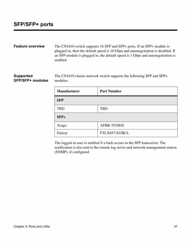
Feature overview The CN1610 switch supports 16 SFP and SFP+ ports. If an SFP+ module is plugged in, then the default speed is 10 Gbps and autonegotiation is disabled. If an SFP module is plugged in, the default speed is 1 Gbps and autonegotiation is enabled.
Supported SFP/SFP+ modules
The CN1610 cluster network switch supports the following SFP and SFP+ modules:
The logged-in user is notified if a fault occurs in the SFP transceiver. The notification is also sent to the remote log server and network management station (SNMP), if configured.
Manufacturer Part Number
SFP
TBD TBD
SFP+
Avago AFBR-703SDZ
Finisar FTLX8571D3BCL
Chapter 3: Ports and LAGs 47
Link aggregation
Feature overview The CN1610 switch supports link aggregation as specified in the IEEE Standard 802.1AX, 2005 edition. Link aggregation enables one or more full-duplex (FDX) Ethernet links to be aggregated together to form a Link Aggregation Group (LAG). The switch treats the LAG as if it were a single link.
From a system perspective, a LAG is treated as a physical port. You can configure LAG properties such as the administrative status, port priority, and path cost using the same commands you use for physical ports.
A failure of one or more of the links in the LAG does not stop traffic in any manner. Upon failure, the flows mapped to a link are dynamically reassigned to the remaining links of the LAG. Similarly, when links are added to a LAG, the conversations may be shifted to the new link.
Static and dynamic LAGs
The CN1610 switch also supports static LAGs. When a port is added to a LAG as a static member, it neither transmits nor receives LACPDUs. Configured members are added to the LAG (active participation) immediately if the LAG is configured to be static. In case of dynamic LAG there is a wait time of 3 seconds before the port is added to the LAG.
A LAG can be either formed either statically or dynamically, but not both. It cannot have some members participate in the dynamic protocol while other members do not.
The CN1610 switch supports up to eight LAGs with eight member ports per LAG. Within a stack, LAG members can span different units.
LAG interface notation
When you create a LAG, you assign it a name. The switch also assigns a logical interface number that uses the slot/port conventions of switch ports. The slot number differentiates LAGs (slot 3) from ports (slot 0).
LAG hashing The purpose of link aggregation is to increase bandwidth between two switches. It is achieved by aggregating multiple ports in one logical group. A common problem of port channels is the possibility of changing the packet’s order in a
48 Link aggregation
particular TCP session. The resolution of this problem is to select the correct physical port within the port channel for transmitting the packet to keep original packets order.
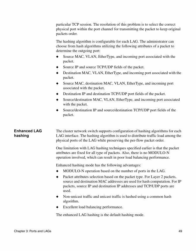
The hashing algorithm is configurable for each LAG. The administrator can choose from hash algorithms utilizing the following attributes of a packet to determine the outgoing port:
◆ Source MAC, VLAN, EtherType, and incoming port associated with the packet.
◆ Source IP and source TCP/UDP fields of the packet.
◆ Destination MAC, VLAN, EtherType, and incoming port associated with the packet.
◆ Source MAC, destination MAC, VLAN, EtherType, and incoming port associated with the packet.
◆ Destination IP and destination TCP/UDP port fields of the packet.
◆ Source/destination MAC, VLAN, EtherType, and incoming port associated with the packet.
◆ Source/destination IP and source/destination TCP/UDP port fields of the packet.
Enhanced LAG hashing
The cluster network switch supports configuration of hashing algorithms for each LAG interface. The hashing algorithm is used to distribute traffic load among the physical ports of the LAG while preserving the per-flow packet order.
One limitation with LAG hashing techniques specified earlier is that the packet attributes are fixed for all type of packets. Also, there is no MODULO-N operation involved, which can result in poor load balancing performance.
Enhanced hashing mode has the following advantages:
◆ MODULO-N operation based on the number of ports in the LAG.
◆ Packet attributes selection based on the packet type. For Layer 2 packets, source and destination MAC addresses are used for hash computation. For IP packets, source IP and destination IP addresses and TCP/UDP ports are used.
◆ Non-unicast traffic and unicast traffic is hashed using a common hash algorithm.
◆ Excellent load balancing performance.
The enhanced LAG hashing is the default hashing mode.
Chapter 3: Ports and LAGs 49
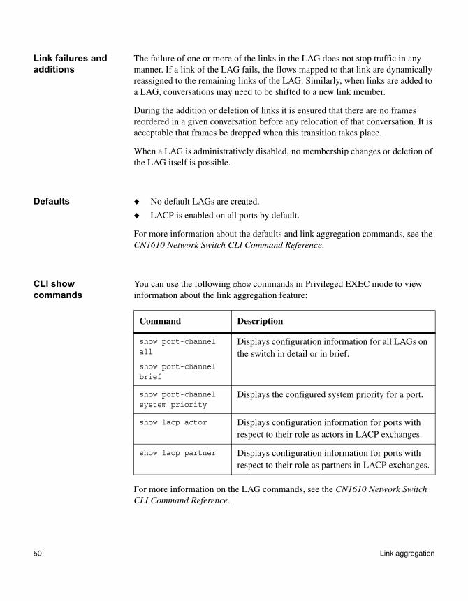
Link failures and additions
The failure of one or more of the links in the LAG does not stop traffic in any manner. If a link of the LAG fails, the flows mapped to that link are dynamically reassigned to the remaining links of the LAG. Similarly, when links are added to a LAG, conversations may need to be shifted to a new link member.
During the addition or deletion of links it is ensured that there are no frames reordered in a given conversation before any relocation of that conversation. It is acceptable that frames be dropped when this transition takes place.
When a LAG is administratively disabled, no membership changes or deletion of the LAG itself is possible.
Defaults ◆ No default LAGs are created.
◆ LACP is enabled on all ports by default.
For more information about the defaults and link aggregation commands, see the CN1610 Network Switch CLI Command Reference.
CLI show commands
You can use the following show commands in Privileged EXEC mode to view information about the link aggregation feature:
For more information on the LAG commands, see the CN1610 Network Switch CLI Command Reference.
Command Description
show port-channel all
show port-channel brief
Displays configuration information for all LAGs on the switch in detail or in brief.
show port-channel system priority
Displays the configured system priority for a port.
show lacp actor Displays configuration information for ports with respect to their role as actors in LACP exchanges.
show lacp partner Displays configuration information for ports with respect to their role as partners in LACP exchanges.
50 Link aggregation
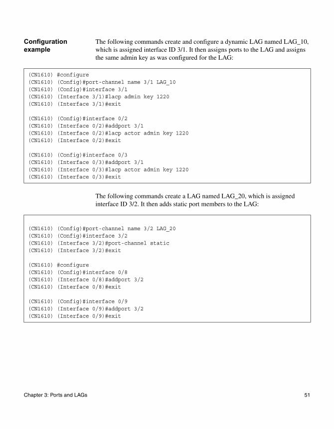
Configuration example
The following commands create and configure a dynamic LAG named LAG_10, which is assigned interface ID 3/1. It then assigns ports to the LAG and assigns the same admin key as was configured for the LAG:
The following commands create a LAG named LAG_20, which is assigned interface ID 3/2. It then adds static port members to the LAG:
(CN1610) #configure(CN1610) (Config)#port-channel name 3/1 LAG_10(CN1610) (Config)#interface 3/1(CN1610) (Interface 3/1)#lacp admin key 1220(CN1610) (Interface 3/1)#exit
(CN1610) (Config)#interface 0/2(CN1610) (Interface 0/2)#addport 3/1(CN1610) (Interface 0/2)#lacp actor admin key 1220(CN1610) (Interface 0/2)#exit
(CN1610) (Config)#interface 0/3(CN1610) (Interface 0/3)#addport 3/1(CN1610) (Interface 0/3)#lacp actor admin key 1220(CN1610) (Interface 0/3)#exit
(CN1610) (Config)#port-channel name 3/2 LAG_20(CN1610) (Config)#interface 3/2(CN1610) (Interface 3/2)#port-channel static(CN1610) (Interface 3/2)#exit
(CN1610) #configure(CN1610) (Config)#interface 0/8(CN1610) (Interface 0/8)#addport 3/2(CN1610) (Interface 0/8)#exit
(CN1610) (Config)#interface 0/9(CN1610) (Interface 0/9)#addport 3/2(CN1610) (Interface 0/9)#exit
Chapter 3: Ports and LAGs 51

52 Link aggregation
Chapter 4: Switching
4
SwitchingAbout this chapter This chapter describes how to configure and view status information for Layer 2 switching protocols.
Topics in this chapter
This chapter includes the following topics:
◆ “Layer 2 forwarding database” on page 54
◆ “Layer 2 multicast forwarding database” on page 56
◆ “Link Layer Discovery Protocol” on page 58
◆ “Industry Standard Discovery Protocol” on page 62
◆ “IGMP snooping” on page 66
◆ “Jumbo frames” on page 69
◆ “Port mirroring” on page 70
◆ “Flow-based mirroring” on page 72
◆ “Storm control” on page 74
◆ “Flow control” on page 76
53
Layer 2 forwarding database
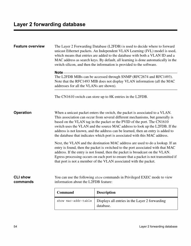
Feature overview The Layer 2 Forwarding Database (L2FDB) is used to decide where to forward unicast Ethernet packets. An Independent VLAN Learning (IVL) model is used, which means that entries are added to the database with both a VLAN ID and a MAC address as search keys. By default, all learning is done automatically in the switch silicon, and then the information is provided to the software.
NoteThe L2FDB MIBs can be accessed through SNMP (RFC2674 and RFC1493). Note that the RFC1493 MIB does not display VLAN information (all the MAC addresses for all the VLANs are shown).
The CN1610 switch can store up to 8K entries in the L2FDB.
Operation When a unicast packet enters the switch, the packet is associated to a VLAN. This association can occur from several different mechanisms, but generally is based on the VLAN tag in the packet or the PVID of the port. The CN1610 switch uses the VLAN and the source MAC address to look up the L2FDB. If the address is not known, and the address can be learned, then an entry is added to the database that indicates which port is associated with this MAC address.
Next, the VLAN and the destination MAC address are used to do a lookup. If an entry is found, then the packet is switched to the port associated with that MAC address. If the entry is not found, then the packet is broadcast on the VLAN. Egress processing occurs on each port to ensure that a packet is not transmitted if that port is not a member of the VLAN associated with the packet.
CLI show commands
You can use the following show commands in Privileged EXEC mode to view information about the L2FDB feature:
Command Description
show mac-addr-table Displays all entries in the Layer 2 forwarding database.
54 Layer 2 forwarding database
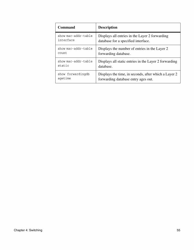
show mac-addr-table interface
Displays all entries in the Layer 2 forwarding database for a specified interface.
show mac-addr-table count
Displays the number of entries in the Layer 2 forwarding database.
show mac-addr-table static
Displays all static entries in the Layer 2 forwarding database.
show forwardingdb agetime
Displays the time, in seconds, after which a Layer 2 forwarding database entry ages out.
Command Description
Chapter 4: Switching 55
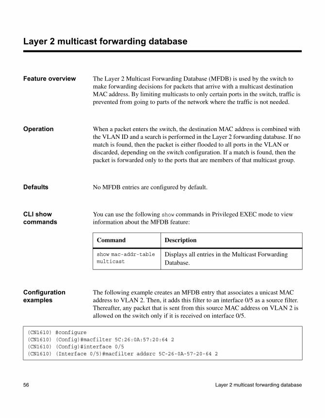
Layer 2 multicast forwarding database
Feature overview The Layer 2 Multicast Forwarding Database (MFDB) is used by the switch to make forwarding decisions for packets that arrive with a multicast destination MAC address. By limiting multicasts to only certain ports in the switch, traffic is prevented from going to parts of the network where the traffic is not needed.
Operation When a packet enters the switch, the destination MAC address is combined with the VLAN ID and a search is performed in the Layer 2 forwarding database. If no match is found, then the packet is either flooded to all ports in the VLAN or discarded, depending on the switch configuration. If a match is found, then the packet is forwarded only to the ports that are members of that multicast group.
Defaults No MFDB entries are configured by default.
CLI show commands
You can use the following show commands in Privileged EXEC mode to view information about the MFDB feature:
Configuration examples
The following example creates an MFDB entry that associates a unicast MAC address to VLAN 2. Then, it adds this filter to an interface 0/5 as a source filter. Thereafter, any packet that is sent from this source MAC address on VLAN 2 is allowed on the switch only if it is received on interface 0/5.
Command Description
show mac-addr-table multicast
Displays all entries in the Multicast Forwarding Database.
(CN1610) #configure(CN1610) (Config)#macfilter 5C:26:0A:57:20:64 2(CN1610) (Config)#interface 0/5(CN1610) (Interface 0/5)#macfilter addsrc 5C-26-0A-57-20-64 2
56 Layer 2 multicast forwarding database
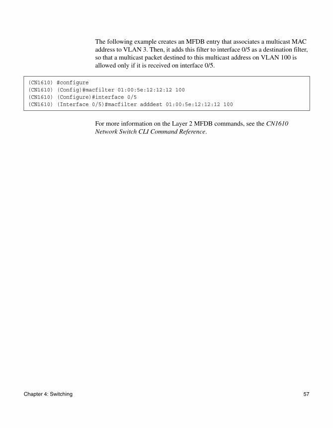
The following example creates an MFDB entry that associates a multicast MAC address to VLAN 3. Then, it adds this filter to interface 0/5 as a destination filter, so that a multicast packet destined to this multicast address on VLAN 100 is allowed only if it is received on interface 0/5.
For more information on the Layer 2 MFDB commands, see the CN1610 Network Switch CLI Command Reference.
(CN1610) #configure(CN1610) (Config)#macfilter 01:00:5e:12:12:12 100(CN1610) (Configure)#interface 0/5(CN1610) (Interface 0/5)#macfilter adddest 01:00:5e:12:12:12 100
Chapter 4: Switching 57
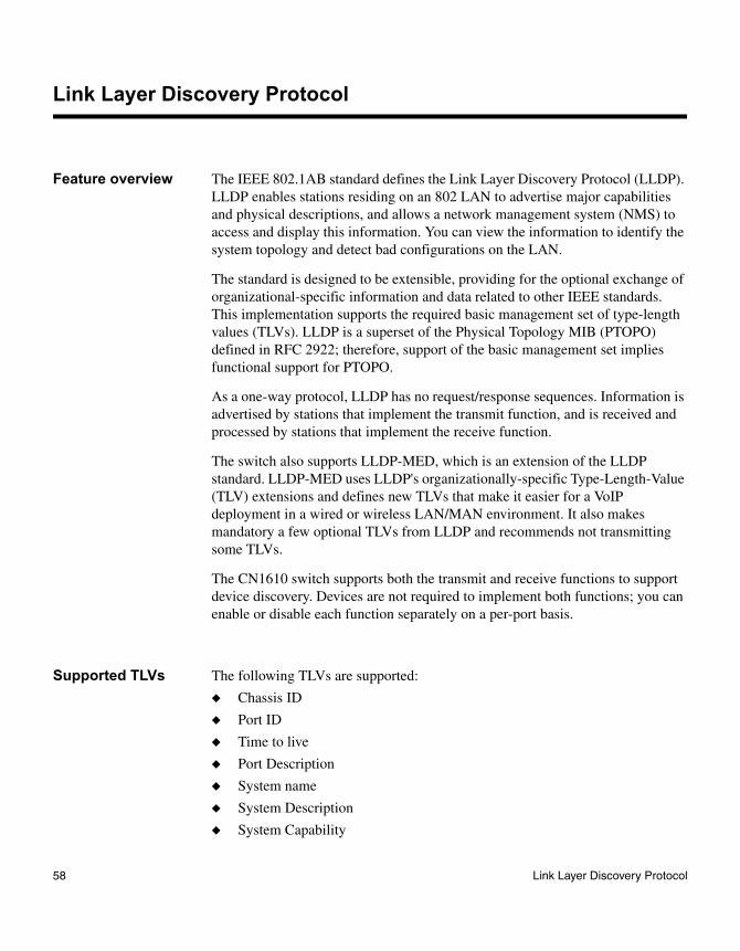
Link Layer Discovery Protocol
Feature overview The IEEE 802.1AB standard defines the Link Layer Discovery Protocol (LLDP). LLDP enables stations residing on an 802 LAN to advertise major capabilities and physical descriptions, and allows a network management system (NMS) to access and display this information. You can view the information to identify the system topology and detect bad configurations on the LAN.
The standard is designed to be extensible, providing for the optional exchange of organizational-specific information and data related to other IEEE standards. This implementation supports the required basic management set of type-length values (TLVs). LLDP is a superset of the Physical Topology MIB (PTOPO) defined in RFC 2922; therefore, support of the basic management set implies functional support for PTOPO.
As a one-way protocol, LLDP has no request/response sequences. Information is advertised by stations that implement the transmit function, and is received and processed by stations that implement the receive function.
The switch also supports LLDP-MED, which is an extension of the LLDP standard. LLDP-MED uses LLDP's organizationally-specific Type-Length-Value (TLV) extensions and defines new TLVs that make it easier for a VoIP deployment in a wired or wireless LAN/MAN environment. It also makes mandatory a few optional TLVs from LLDP and recommends not transmitting some TLVs.
The CN1610 switch supports both the transmit and receive functions to support device discovery. Devices are not required to implement both functions; you can enable or disable each function separately on a per-port basis.
Supported TLVs The following TLVs are supported:
◆ Chassis ID
◆ Port ID
◆ Time to live
◆ Port Description
◆ System name
◆ System Description
◆ System Capability
58 Link Layer Discovery Protocol
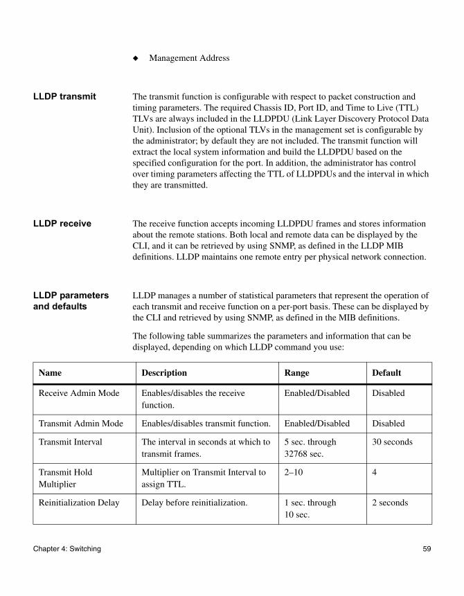
◆ Management Address
LLDP transmit The transmit function is configurable with respect to packet construction and timing parameters. The required Chassis ID, Port ID, and Time to Live (TTL) TLVs are always included in the LLDPDU (Link Layer Discovery Protocol Data Unit). Inclusion of the optional TLVs in the management set is configurable by the administrator; by default they are not included. The transmit function will extract the local system information and build the LLDPDU based on the specified configuration for the port. In addition, the administrator has control over timing parameters affecting the TTL of LLDPDUs and the interval in which they are transmitted.
LLDP receive The receive function accepts incoming LLDPDU frames and stores information about the remote stations. Both local and remote data can be displayed by the CLI, and it can be retrieved by using SNMP, as defined in the LLDP MIB definitions. LLDP maintains one remote entry per physical network connection.
LLDP parameters and defaults
LLDP manages a number of statistical parameters that represent the operation of each transmit and receive function on a per-port basis. These can be displayed by the CLI and retrieved by using SNMP, as defined in the MIB definitions.
The following table summarizes the parameters and information that can be displayed, depending on which LLDP command you use:
Name Description Range Default
Receive Admin Mode Enables/disables the receive function.
Enabled/Disabled Disabled
Transmit Admin Mode Enables/disables transmit function. Enabled/Disabled Disabled
Transmit Interval The interval in seconds at which to transmit frames.
5 sec. through 32768 sec.
30 seconds
Transmit Hold Multiplier
Multiplier on Transmit Interval to assign TTL.
2–10 4
Reinitialization Delay Delay before reinitialization. 1 sec. through 10 sec.
2 seconds
Chapter 4: Switching 59
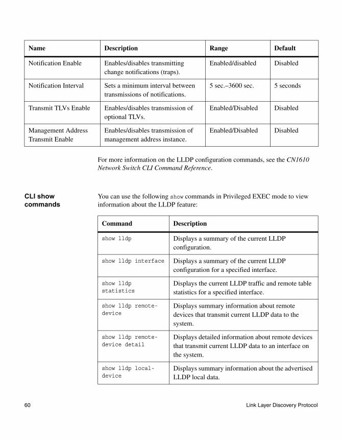
For more information on the LLDP configuration commands, see the CN1610 Network Switch CLI Command Reference.
CLI show commands
You can use the following show commands in Privileged EXEC mode to view information about the LLDP feature:
Notification Enable Enables/disables transmitting change notifications (traps).
Enabled/disabled Disabled
Notification Interval Sets a minimum interval between transmissions of notifications.
5 sec.–3600 sec. 5 seconds
Transmit TLVs Enable Enables/disables transmission of optional TLVs.
Enabled/Disabled Disabled
Management Address Transmit Enable
Enables/disables transmission of management address instance.
Enabled/Disabled Disabled
Name Description Range Default
Command Description
show lldp Displays a summary of the current LLDP configuration.
show lldp interface Displays a summary of the current LLDP configuration for a specified interface.
show lldp statistics
Displays the current LLDP traffic and remote table statistics for a specified interface.
show lldp remote-device
Displays summary information about remote devices that transmit current LLDP data to the system.
show lldp remote-device detail
Displays detailed information about remote devices that transmit current LLDP data to an interface on the system.
show lldp local-device
Displays summary information about the advertised LLDP local data.
60 Link Layer Discovery Protocol
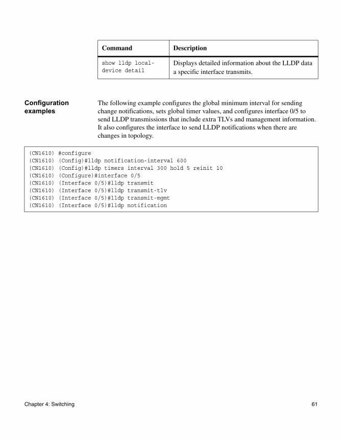
Configuration examples
The following example configures the global minimum interval for sending change notifications, sets global timer values, and configures interface 0/5 to send LLDP transmissions that include extra TLVs and management information. It also configures the interface to send LLDP notifications when there are changes in topology.
show lldp local-device detail
Displays detailed information about the LLDP data a specific interface transmits.
Command Description
(CN1610) #configure(CN1610) (Config)#lldp notification-interval 600(CN1610) (Config)#lldp timers interval 300 hold 5 reinit 10(CN1610) (Configure)#interface 0/5(CN1610) (Interface 0/5)#lldp transmit(CN1610) (Interface 0/5)#lldp transmit-tlv(CN1610) (Interface 0/5)#lldp transmit-mgmt(CN1610) (Interface 0/5)#lldp notification
Chapter 4: Switching 61
Industry Standard Discovery Protocol
Feature overview Industry Standard Discovery Protocol (ISDP) is a proprietary Layer 2 network protocol which interoperates with Cisco network equipment and is used to share information between neighboring devices (routers, bridges, access servers, and switches).
Through the operation of ISDP, the switch can discover information about its neighbors, such as:
◆ Device identifier
◆ Port ID
◆ Remote device model (Device ID + Software version + Platform + Capabilities)
Every ISDP-capable device periodically broadcasts ISDP messages and listens to receive broadcasts from other devices.
The ISDP feature interoperates with Cisco devices running the Cisco Discovery Protocol (CDP). ISDP is compatible with CDP versions 1 and 2. Only selected fields are supported.
Operation ISDP devices send announcements to the multicast destination address 01-00-0c-cc-cc-cc. (This address is also used for Cisco proprietary protocols such as CDP and VTP.) ISDP packets are transmitted using SNAP encapsulation, with type code 2000.
ISDP announcements are sent periodically on physical Ethernet interfaces. Each device that supports ISDP stores the information received from other devices in a table, which you can use the CLI to view. The ISDP table's information is refreshed each time an announcement is received, and the hold time for that entry is reset. The hold time specifies how long an entry in the table will be kept. If no announcements are received from a device and the hold time timer expires for that entry, the device's information is discarded.
The information contained in ISDP announcements varies by the type of device and the version of the operating system running on it. Information contained includes the operating system version, host name, and every address for every protocol configured on the port where CDP frame is sent. For example, this information can include the port's IP address, the port identifier from which the announcement was sent, the device type, and the model.
62 Industry Standard Discovery Protocol
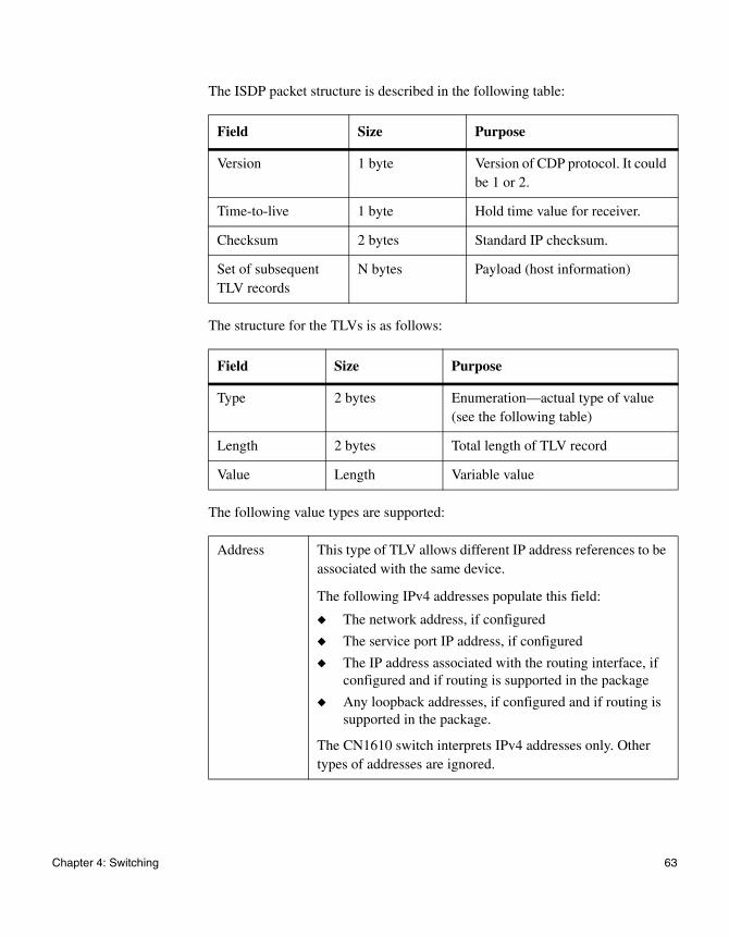
The ISDP packet structure is described in the following table:
The structure for the TLVs is as follows:
The following value types are supported:
Field Size Purpose
Version 1 byte Version of CDP protocol. It could be 1 or 2.
Time-to-live 1 byte Hold time value for receiver.
Checksum 2 bytes Standard IP checksum.
Set of subsequent TLV records
N bytes Payload (host information)
Field Size Purpose
Type 2 bytes Enumeration—actual type of value (see the following table)
Length 2 bytes Total length of TLV record
Value Length Variable value
Address This type of TLV allows different IP address references to be associated with the same device.
The following IPv4 addresses populate this field:
◆ The network address, if configured
◆ The service port IP address, if configured
◆ The IP address associated with the routing interface, if configured and if routing is supported in the package
◆ Any loopback addresses, if configured and if routing is supported in the package.
The CN1610 switch interprets IPv4 addresses only. Other types of addresses are ignored.
Chapter 4: Switching 63
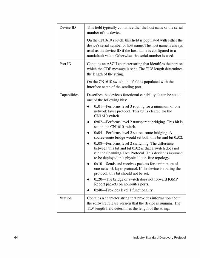
Device ID This field typically contains either the host name or the serial number of the device.
On the CN1610 switch, this field is populated with either the device's serial number or host name. The host name is always used as the device ID if the host name is configured to a nondefault value. Otherwise, the serial number is used.
Port ID Contains an ASCII character string that identifies the port on which the CDP message is sent. The TLV length determines the length of the string.
On the CN1610 switch, this field is populated with the interface name of the sending port.
Capabilities Describes the device's functional capability. It can be set to one of the following bits:
◆ 0x01—Performs level 3 routing for a minimum of one network layer protocol. This bit is cleared for the CN1610 switch.
◆ 0x02—Performs level 2 transparent bridging. This bit is set on the CN1610 switch.
◆ 0x04—Performs level 2 source-route bridging. A source-route bridge would set both this bit and bit 0x02.
◆ 0x08—Performs level 2 switching. The difference between this bit and bit 0x02 is that a switch does not run the Spanning-Tree Protocol. This device is assumed to be deployed in a physical loop-free topology.
◆ 0x10—Sends and receives packets for a minimum of one network layer protocol. If the device is routing the protocol, this bit should not be set.
◆ 0x20—The bridge or switch does not forward IGMP Report packets on nonrouter ports.
◆ 0x40—Provides level 1 functionality.
Version Contains a character string that provides information about the software release version that the device is running. The TLV length field determines the length of the string.
64 Industry Standard Discovery Protocol
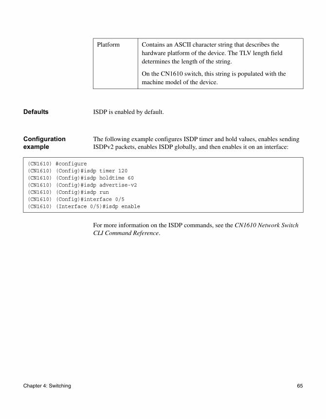
Defaults ISDP is enabled by default.
Configuration example
The following example configures ISDP timer and hold values, enables sending ISDPv2 packets, enables ISDP globally, and then enables it on an interface:
For more information on the ISDP commands, see the CN1610 Network Switch CLI Command Reference.
Platform Contains an ASCII character string that describes the hardware platform of the device. The TLV length field determines the length of the string.
On the CN1610 switch, this string is populated with the machine model of the device.
(CN1610) #configure(CN1610) (Config)#isdp timer 120(CN1610) (Config)#isdp holdtime 60(CN1610) (Config)#isdp advertise-v2(CN1610) (Config)#isdp run(CN1610) (Config)#interface 0/5(CN1610) (Interface 0/5)#isdp enable
Chapter 4: Switching 65

IGMP snooping
Feature overview A traditional Ethernet network may be separated into different network segments to prevent placing too many devices onto the same shared media. Bridges and switches connect these segments. When a packet with a broadcast or multicast destination address is received, the switch will forward a copy into each of the remaining network segments in accordance with the IEEE MAC Bridge standard. Eventually, the packet is made accessible to all nodes connected to the network. This approach works well for broadcast packets that are intended to be seen or processed by all connected nodes. In the case of multicast packets, however, this approach could lead to less efficient use of network bandwidth, particularly when the packet is intended for only a small number of nodes.
IGMP snooping helps conserve switch bandwidth by preventing multicast traffic from being forwarded on segments of the network where no node has expressed interest in receiving packets addressed to group address. This contrasts with normal switch behavior, where multicast traffic is typically forwarded on all interfaces; that is, packets will be flooded into network segments where no node has any interest in receiving the packet. IGMP snooping is also supported at the VLAN level.
Enabling switches to snoop IGMP packets is a creative way to solve this problem. The CN1610 switch uses the information in the IGMP packets as they are being forwarded throughout the network to determine which segments should receive packets directed to the group address. Multicast IP traffic is traffic that is destined to a host group. Host groups are identified by class D IP addresses, which range from 224.0.0.0 to 239.255.255.255. Based on the IGMP query and report messages, the switch forwards traffic only to the ports that request the multicast traffic. This prevents the switch from broadcasting the traffic to all ports and possibly affecting network performance.
Implementation of IGMP snooping
The IGMP snooping feature conforms with the IETF draft “Considerations for IGMP and MLD Snooping Switches,” version 10, October 2003. The CN1610 switch implementation supports basic IGMPv3 functionality for processing IGMPv3 join reports in the same manner in which IGMPv2 joins are processed; that is, without giving consideration to the source address.
66 IGMP snooping
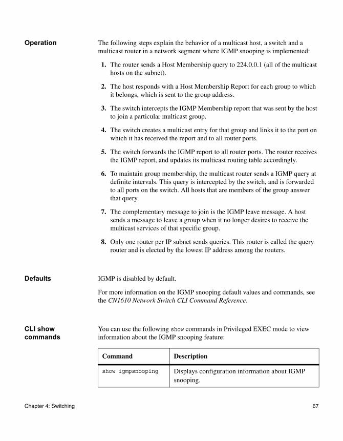
Operation The following steps explain the behavior of a multicast host, a switch and a multicast router in a network segment where IGMP snooping is implemented:
1. The router sends a Host Membership query to 224.0.0.1 (all of the multicast hosts on the subnet).
2. The host responds with a Host Membership Report for each group to which it belongs, which is sent to the group address.
3. The switch intercepts the IGMP Membership report that was sent by the host to join a particular multicast group.
4. The switch creates a multicast entry for that group and links it to the port on which it has received the report and to all router ports.
5. The switch forwards the IGMP report to all router ports. The router receives the IGMP report, and updates its multicast routing table accordingly.
6. To maintain group membership, the multicast router sends a IGMP query at definite intervals. This query is intercepted by the switch, and is forwarded to all ports on the switch. All hosts that are members of the group answer that query.
7. The complementary message to join is the IGMP leave message. A host sends a message to leave a group when it no longer desires to receive the multicast services of that specific group.
8. Only one router per IP subnet sends queries. This router is called the query router and is elected by the lowest IP address among the routers.
Defaults IGMP is disabled by default.
For more information on the IGMP snooping default values and commands, see the CN1610 Network Switch CLI Command Reference.
CLI show commands
You can use the following show commands in Privileged EXEC mode to view information about the IGMP snooping feature:
Command Description
show igmpsnooping Displays configuration information about IGMP snooping.
Chapter 4: Switching 67
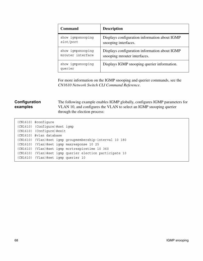
For more information on the IGMP snooping and querier commands, see the CN1610 Network Switch CLI Command Reference.
Configuration examples
The following example enables IGMP globally, configures IGMP parameters for VLAN 10, and configures the VLAN to select an IGMP snooping querier through the election process:
show igmpsnooping slot/port
Displays configuration information about IGMP snooping interfaces.
show igmpsnooping mrouter interface
Displays configuration information about IGMP snooping mrouter interfaces.
show igmpsnooping querier
Displays IGMP snooping querier information.
Command Description
(CN1610) #configure(CN1610) (Configure)#set igmp(CN1610) (Configure)#exit(CN1610) #vlan database(CN1610) (Vlan)#set igmp groupmembership-interval 10 180(CN1610) (Vlan)#set igmp maxresponse 10 25(CN1610) (Vlan)#set igmp mcrtrexpiretime 10 360(CN1610) (Vlan)#set igmp querier election participate 10(CN1610) (Vlan)#set igmp querier 10
68 IGMP snooping
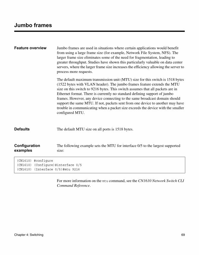
Jumbo frames
Feature overview Jumbo frames are used in situations where certain applications would benefit from using a large frame size (for example, Network File System, NFS). The larger frame size eliminates some of the need for fragmentation, leading to greater throughput. Studies have shown this particularly valuable on data center servers, where the larger frame size increases the efficiency allowing the server to process more requests.
The default maximum transmission unit (MTU) size for this switch is 1518 bytes (1522 bytes with VLAN header). The jumbo frames feature extends the MTU size on this switch to 9216 bytes. This switch assumes that all packets are in Ethernet format. There is currently no standard defining support of jumbo frames. However, any device connecting to the same broadcast domain should support the same MTU. If not, packets sent from one device to another may have trouble in communicating when a packet size exceeds the device with the smaller configured MTU.
Defaults The default MTU size on all ports is 1518 bytes.
Configuration examples
The following example sets the MTU for interface 0/5 to the largest supported size:
For more information on the mtu command, see the CN1610 Network Switch CLI Command Reference.
(CN1610) #configure(CN1610) (Configure)#interface 0/5(CN1610) (Interface 0/5)#mtu 9216
Chapter 4: Switching 69
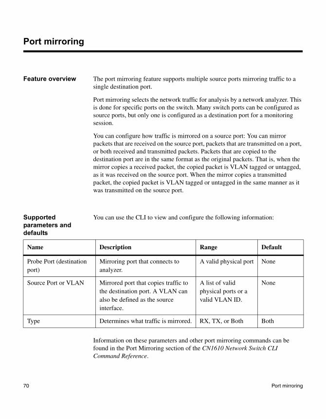
Port mirroring
Feature overview The port mirroring feature supports multiple source ports mirroring traffic to a single destination port.
Port mirroring selects the network traffic for analysis by a network analyzer. This is done for specific ports on the switch. Many switch ports can be configured as source ports, but only one is configured as a destination port for a monitoring session.
You can configure how traffic is mirrored on a source port: You can mirror packets that are received on the source port, packets that are transmitted on a port, or both received and transmitted packets. Packets that are copied to the destination port are in the same format as the original packets. That is, when the mirror copies a received packet, the copied packet is VLAN tagged or untagged, as it was received on the source port. When the mirror copies a transmitted packet, the copied packet is VLAN tagged or untagged in the same manner as it was transmitted on the source port.
Supported parameters and defaults
You can use the CLI to view and configure the following information:
Information on these parameters and other port mirroring commands can be found in the Port Mirroring section of the CN1610 Network Switch CLI Command Reference.
Name Description Range Default
Probe Port (destination port)
Mirroring port that connects to analyzer.
A valid physical port None
Source Port or VLAN Mirrored port that copies traffic to the destination port. A VLAN can also be defined as the source interface.
A list of valid physical ports or a valid VLAN ID.
None
Type Determines what traffic is mirrored. RX, TX, or Both Both
70 Port mirroring
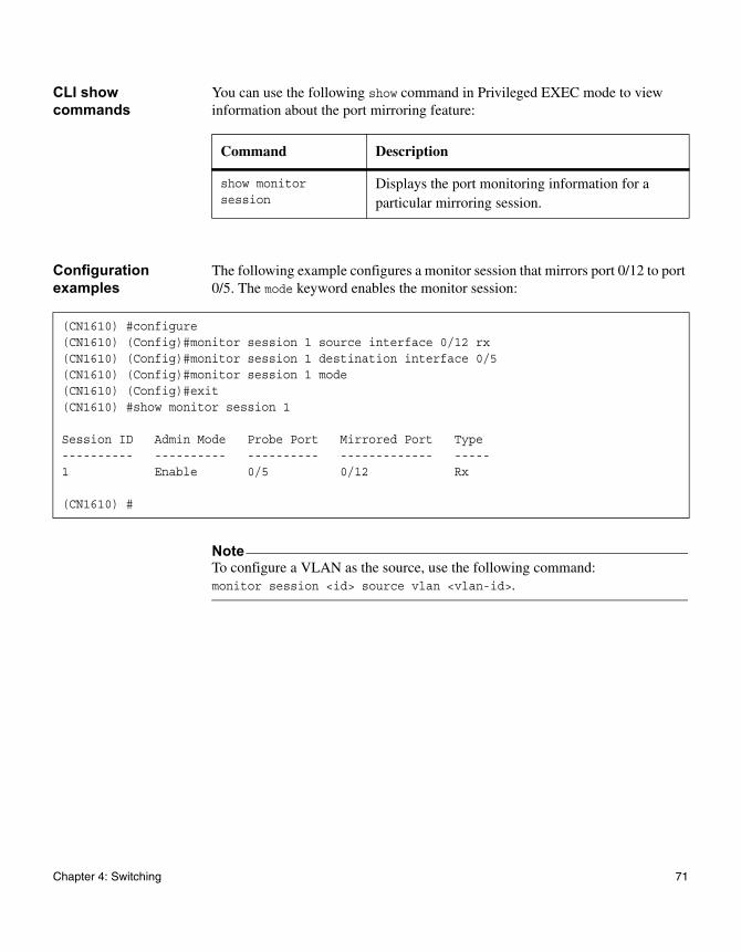
CLI show commands
You can use the following show command in Privileged EXEC mode to view information about the port mirroring feature:
Configuration examples
The following example configures a monitor session that mirrors port 0/12 to port 0/5. The mode keyword enables the monitor session:
NoteTo configure a VLAN as the source, use the following command: monitor session <id> source vlan <vlan-id>.
Command Description
show monitor session
Displays the port monitoring information for a particular mirroring session.
(CN1610) #configure(CN1610) (Config)#monitor session 1 source interface 0/12 rx(CN1610) (Config)#monitor session 1 destination interface 0/5(CN1610) (Config)#monitor session 1 mode(CN1610) (Config)#exit(CN1610) #show monitor session 1
Session ID Admin Mode Probe Port Mirrored Port Type---------- ---------- ---------- ------------- -----1 Enable 0/5 0/12 Rx
(CN1610) #
Chapter 4: Switching 71
Flow-based mirroring
Feature overview Flow-based mirroring enables you to copy certain types of traffic to a single destination port. This provides flexibility in mirroring traffic, because instead of mirroring all ingress or egress traffic on a port, the switch can mirror a subset of that traffic. You can configure to the switch to mirror flows based on Layer 2, Layer 3, and Layer 4 information.
When a packet enters the switch, the normal Layer 2 and Layer 3 processing occurs. Next, the packet content is compared against user-defined traffic classifications. If there is a match, then one or more actions can be taken. In the case of flow-based mirroring, that action is to copy the packet to a destination port.
Configuration overview
The following is the general procedure for configuring this feature:
1. Define a traffic class. The traffic class can use Layer 2 through Layer 4 packet information as part of the match criteria.
2. Create a DiffServ policy that mirrors traffic that matches the class criteria to a selected destination port.
Any packet received on a port that is participating in flow-based mirroring is compared to the user-defined rules. If the packet matches a defined flow, then it is copied to the destination port in addition to the normal forwarding destination.
See Chapter 7, “Quality of Service,” on page 115 for information about configuring traffic classes and creating a DiffServ policy that mirrors the class to a port.
Defaults No flow-based mirroring configuration is present by default.
Configuration example
The following example enables DiffServ, creates an IPv4 traffic class named class_igmp that matches all IGMP traffic, and creates a policy that mirrors that traffic to port 0/7. Finally, the policy is applied to traffic on interface 0/4.
72 Flow-based mirroring
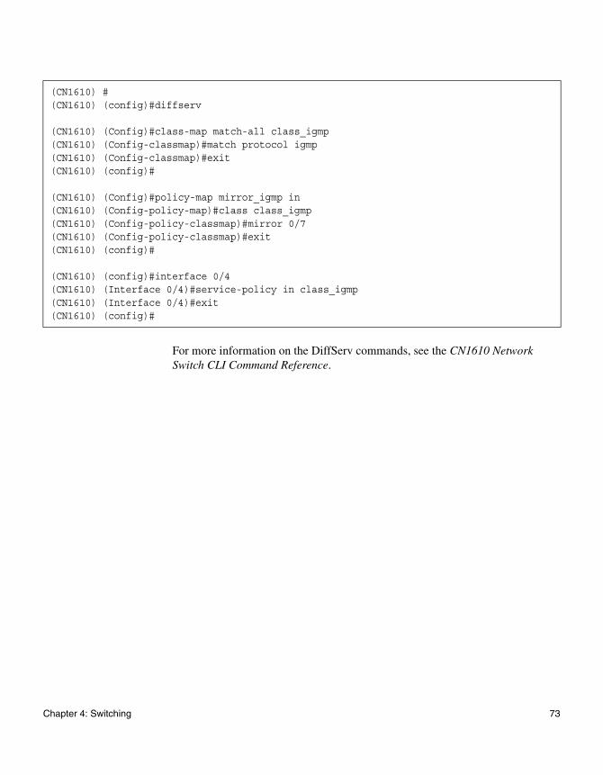
For more information on the DiffServ commands, see the CN1610 Network Switch CLI Command Reference.
(CN1610) #(CN1610) (config)#diffserv
(CN1610) (Config)#class-map match-all class_igmp(CN1610) (Config-classmap)#match protocol igmp(CN1610) (Config-classmap)#exit(CN1610) (config)#
(CN1610) (Config)#policy-map mirror_igmp in(CN1610) (Config-policy-map)#class class_igmp(CN1610) (Config-policy-classmap)#mirror 0/7(CN1610) (Config-policy-classmap)#exit(CN1610) (config)#
(CN1610) (config)#interface 0/4(CN1610) (Interface 0/4)#service-policy in class_igmp(CN1610) (Interface 0/4)#exit(CN1610) (config)#
Chapter 4: Switching 73
Storm control
Feature overview The storm control feature provides the ability to detect a traffic storm (broadcast, multicast, or unknown unicast traffic received at a very high rate) and prevent these packets from flooding other parts of the network.
When storm control is enabled, broadcast, multicast, or unknown unicast traffic begins to drop when that type of traffic exceeds the configured rate threshold for a particular port. The traffic resumes when the traffic rate returns to a level below the threshold.
The storm control feature supports two additional actions, shutdown and trap, for each storm control type on a per-port level. When a storm condition is detected on a port where the shutdown action is enabled, the port is disabled. The port can only be re-enabled manually by the administrator. If the trap action is enabled, a trap is sent to the system log.
Storm control can be enabled or disabled per port; by default, this feature is disabled for all ports. When enabled, storms are detected based on a configurable rate that is defined as a percentage of a link's capability. The default rate is five percent, which is used for all ports if another rate is not defined. Additionally, unknown unicast (destination lookup failures) and multicast traffic can be included in the storm control feature. Each can be enabled/disabled separately per port and have a rate configured for that port.
Note that the hardware counters track multicast packets and unknown unicast packets separate from each other (and separate from the broadcast packets). A rate of five percent means that each traffic type will be allowed to reach that threshold before storm control is applied.
NoteThe actual rate of ingress traffic required to activate storm control is based on the size of incoming packets and the hard-coded average packet size 512 bytes (used to calculate a packet-per-second rate), as the forwarding-plane requires pps versus an absolute rate kbps. For example if the configured limit is 10 percent, this is converted to ~25000 pps and this pps limit is set in the hardware. Users will get the approximately desired output when 512 bytes packets are used.
74 Storm control
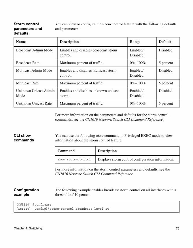
Storm control parameters and defaults
You can view or configure the storm control feature with the following defaults and parameters:
For more information on the parameters and defaults for the storm control commands, see the CN1610 Network Switch CLI Command Reference.
CLI show commands
You can use the following show command in Privileged EXEC mode to view information about the storm control feature:
For more information on the storm control parameters and defaults, see the CN1610 Network Switch CLI Command Reference.
Configuration example
The following example enables broadcast storm control on all interfaces with a threshold of 10 percent:
Name Description Range Default
Broadcast Admin Mode Enables and disables broadcast storm control.
Enabled/Disabled
Disabled
Broadcast Rate Maximum percent of traffic. 0%–100% 5 percent
Multicast Admin Mode Enables and disables multicast storm control.
Enabled/Disabled
Disabled
Multicast Rate Maximum percent of traffic. 0%–100% 5 percent
Unknown Unicast Admin Mode
Enables and disables unknown unicast storm.
Enabled/Disabled
Disabled
Unknown Unicast Rate Maximum percent of traffic. 0%–100% 5 percent
Command Description
show storm-control Displays storm control configuration information.
(CN1610) #configure(CN1610) (Config)#storm-control broadcast level 10
Chapter 4: Switching 75

Flow control
Feature overview IEEE 802.3x flow control is specified in IEEE 802.3x. Flow control allows traffic from one device to be throttled for a specified period of time. It is defined for devices that are directly connected. To inhibit transmission of data frames from another device on the LAN, a device transmits a PAUSE frame, as defined in the specification.
Flow control is configurable per port as enabled, disabled, or in auto mode. In auto mode, the ability to send a PAUSE frame is determined based on the autonegotiation resolution for the port (autonegotiation must also be enabled on the port).
Since flow control is implemented only on full-duplex links, there is no ambiguity as to the identity of the devices involved.
Operation When flow control is enabled and a valid PAUSE frame is received on a port, the switch will not transmit frames sent by the switch fabric on that port for the period of time specified in the PAUSE frame. When the specified time has elapsed or a valid PAUSE frame is received on the port containing a zero pause time, the switch again transmits traffic on the port.
The switch initiates the PAUSE operation when the fabric cannot keep up with the amount of frames being switched; this is detected based on the amount of memory used by packets on an input port. When the memory usage meets a certain threshold, the switch transmits a PAUSE frame on the port. If the port continues to receive packets after this operation is applied, the packets are discarded. When the utilization returns to a specified low threshold, the switch sends a PAUSE frame with a pause time of zero, indicating that the remote port can transmit frames again.
Defaults By default, flow control is disabled on all ports.
Configuration example
The following example enables flow control on a port:
76 Flow control

(CN1610) #configure(CN1610) (Config)#interface 0/15(CN1610) (interface 0/15)#flowcontrol
Chapter 4: Switching 77

78 Flow control
Chapter 5: Multiple Spanning Tree Protocol
5
Multiple Spanning Tree ProtocolAbout this chapter This chapter describes the switch software support for IEEE 802.1s, Multiple Spanning Tree Protocol (MSTP).
Topics in this chapter
This chapter discusses the following topics:
◆ “MSTP overview” on page 80
◆ “MSTP functional description” on page 81
◆ “MSTP operation in the network” on page 87
◆ “MSTP CLI show commands” on page 93
◆ “MSTP configuration example” on page 94
79
MSTP overview
MSTP definition IEEE 802.1s, Multiple Spanning Tree Protocol (MSTP), supports multiple instances of Spanning Tree to efficiently channel VLAN traffic over different interfaces.
Each instance of the spanning tree behaves in the manner specified in IEEE 802.1w, Rapid Spanning Tree (RSTP), which specifies the rapid transitioning of the port to the Forwarding state.
MSTP and other spanning tree protocols
The difference between the RSTP and the traditional STP (IEEE 802.1d) is the ability of RSTP to configure and recognize full-duplex connectivity and ports that are connected to end stations, resulting in rapid transitioning of the port to the forwarding state and the suppression of Topology Change Notifications (TCNs). These features are represented by the Edge Port and Point to Point values. MSTP is compatible to both RSTP and STP. It behaves appropriately to STP and RSTP bridges.
An MSTP bridge can be configured to behave entirely as a RSTP bridge or STP bridge. Therefore, an IEEE 802.1s bridge inherently also supports IEEE 802.1w and IEEE 802.1d.
Defaults ◆ Support for MSTP operation is enabled by default.
◆ STP functionality is enabled on all ports by default.
◆ The common and internal spanning tree (CIST) instance (MSTID = 0) is the only default MSTP instance.
For additional default values, see the CN1610 Network Switch CLI Command Reference.
80 MSTP overview
MSTP functional description
Overview The MSTP algorithm and protocol provides simple and full connectivity for frames assigned to any given VLAN throughout a bridged LAN that comprises arbitrarily interconnected networking devices, each operating MSTP, STP, or RSTP. MSTP allows frames assigned to different VLANs to follow separate paths, each based on an independent multiple spanning tree instance (MSTI), within MST regions composed of LANs and MSTP bridges. These regions and the other bridges and LANs are connected into a single common spanning tree (CST) (see IEEE DRAFT P802.1s/D13).
The common and internal spanning tree
MSTP connects all bridges and LANs with a single common and internal spanning tree (CIST). The CIST supports the automatic determination of each MST region, choosing its maximum possible extent. The connectivity calculated for the CIST provides the CST for interconnecting these regions, and an internal spanning tree (IST) within each region. MSTP ensures that:
◆ frames with a given VID are assigned to one and only one of the MSTIs or the IST within the region;
◆ that the assignment is consistent among all the networking devices in the region;
◆ and that the stable connectivity of each MSTI and IST at the boundary of the region matches that of the CST.
Thus, the stable active topology of the bridged LAN with respect to frames consistently classified as belonging to any given VLAN simply and fully connects all LANs and networking devices throughout the network, though frames belonging to different VLANs can take different paths within any region.
BPDUs All bridges, whether they use STP, RSTP, or MSTP, use BDPUs to send configuration messages. These messages assign port roles that determine each port’s participation in a fully and simply connected active topology based on one or more spanning trees. The information communicated is known as the spanning tree priority vector. The BPDU structure for each of these different protocols is unique. An MSTP bridge transmits the appropriate BPDU depending on the received type of BPDU from a particular port.
Chapter 5: Multiple Spanning Tree Protocol 81
The forwarding of BPDUs can be administratively controlled using the following features:
◆ BPDU Guard—When BPDU guard is enabled globally on the switch and a BPDU packet arrives on a port that has been enabled as an edge port, the port is disabled; that is, all the packets transmission/receiving is disabled on that port. A per port flag indicates whether a port has been disabled due the BPDU guard restrictions.
The switches behind the edge ports that have BPDU guard enabled will not be able to influence the overall STP topology. Using the BPDU guard feature can help enforce the STP domain borders and keep the active topology consistent and predictable.
◆ BPDU Filter—When BPDU filtering is enabled on a port, the port drops any BPDUs received. This configuration does not depend on the arrival of BPDUs, unlike the BPDU guard feature.
◆ BPDU Flood—STP must be disabled administratively on a port to enable BPDU flooding. When BPDU flooding is enabled and the port's link is up, a BPDU arriving on the port is flooded to all the ports that are administratively enabled for BPDU flooding and whose link is up.
MST regions An MST region comprises one or more MSTP bridges that have the same MST configuration ID, use the same MSTIs, and have no bridges attached that cannot receive and transmit MSTP BPDUs. The MST configuration ID consists of the following:
1. A Configuration Identifier Format Selector: 1 byte value encoded as zero.
2. A Configuration Name: A 32-byte string.
3. A Configuration Revision Level: A 2-byte value.
4. A Configuration Digest: A 16-byte signature of type HMAC-MD5 created from the MST Configuration Table (a VID to MSTID mapping).
MSTP states As there are multiple instances of spanning tree, an MSTP state is maintained on a per-port, per-instance basis (or on a per-port, per-VLAN basis, as any VLAN can be in one and only one MSTI or CIST). For example, port A can be forwarding for instance 1 while discarding for instance 2. The port states have changed since the IEEE 802.1d specification.
The correlation of the old and new states are as shown in the following table:
82 MSTP functional description
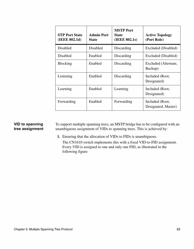
VID to spanning tree assignment
To support multiple spanning trees, an MSTP bridge has to be configured with an unambiguous assignment of VIDs to spanning trees. This is achieved by:
1. Ensuring that the allocation of VIDs to FIDs is unambiguous.
The CN1610 switch implements this with a fixed VID-to-FID assignment. Every VID is assigned to one and only one FID, as illustrated in the following figure:
STP Port State(IEEE 802.1d)
Admin Port State
MSTP Port State (IEEE 802.1s)
Active Topology (Port Role)
Disabled Disabled Discarding Excluded (Disabled)
Disabled Enabled Discarding Excluded (Disabled)
Blocking Enabled Discarding Excluded (Alternate, Backup)
Listening Enabled Discarding Included (Root, Designated)
Learning Enabled Learning Included (Root, Designated)
Forwarding Enabled Forwarding Included (Root, Designated, Master)
Chapter 5: Multiple Spanning Tree Protocol 83
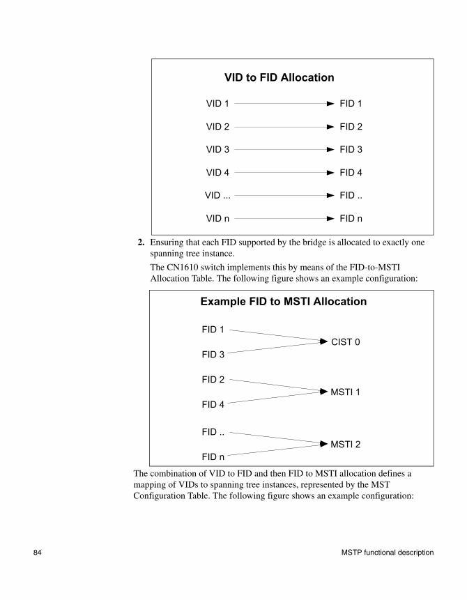
2. Ensuring that each FID supported by the bridge is allocated to exactly one spanning tree instance.
The CN1610 switch implements this by means of the FID-to-MSTI Allocation Table. The following figure shows an example configuration:
The combination of VID to FID and then FID to MSTI allocation defines a mapping of VIDs to spanning tree instances, represented by the MST Configuration Table. The following figure shows an example configuration:
VID 1 FID 1
VID 2 FID 2
VID 3 FID 3
VID 4 FID 4
VID ... FID ..
VID n FID n
VID to FID Allocation
FID 1
FID 3
Example FID to MSTI Allocation
CIST 0
FID 2
FID 4MSTI 1
FID ..
FID nMSTI 2
84 MSTP functional description
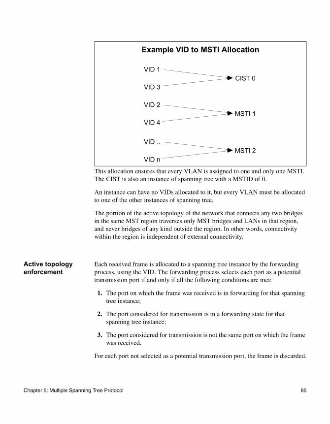
This allocation ensures that every VLAN is assigned to one and only one MSTI. The CIST is also an instance of spanning tree with a MSTID of 0.
An instance can have no VIDs allocated to it, but every VLAN must be allocated to one of the other instances of spanning tree.
The portion of the active topology of the network that connects any two bridges in the same MST region traverses only MST bridges and LANs in that region, and never bridges of any kind outside the region. In other words, connectivity within the region is independent of external connectivity.
Active topology enforcement
Each received frame is allocated to a spanning tree instance by the forwarding process, using the VID. The forwarding process selects each port as a potential transmission port if and only if all the following conditions are met:
1. The port on which the frame was received is in forwarding for that spanning tree instance;
2. The port considered for transmission is in a forwarding state for that spanning tree instance;
3. The port considered for transmission is not the same port on which the frame was received.
For each port not selected as a potential transmission port, the frame is discarded.
VID 1
VID 3
Example VID to MSTI Allocation
CIST 0
VID 2
VID 4MSTI 1
VID ..
VID nMSTI 2
Chapter 5: Multiple Spanning Tree Protocol 85
Control packet behavior
The following list defines how MST control packets are transmitted:
◆ BPDU—Always transmitted as untagged. The port receives and transmits BPDUs in all the three MSTP states (discarding, learning, and forwarding). If MSTP is disabled for the device (manual forwarding on all ports), BPDUs received are switched.
◆ GVRP—Always transmitted as untagged. GVRP PDUs are received and transmitted only when the port is in the forwarding state.
◆ GMRP—GMRP PDUs are transmitted tagged or untagged as per the port's tag setting. They follow the ingress and egress rules.
◆ LACPDU—LACPDUs are always transmitted untagged and are received and transmitted in all the three MSTP states (discarding, learning, and forwarding). These frames are never switched, irrespective if MSTP is enabled or not.
◆ Pause frames—Pause frames are never tagged. They are never switched. The port receives and transmits pause frames in all three MSTP states (discarding, learning, and forwarding). In other words, the STP state of the port has no bearing on the transmission and reception of pause frames.
◆ Other frames to and from the CPU—All other frames are received and transmitted only if the port is in the forwarding state.
86 MSTP functional description
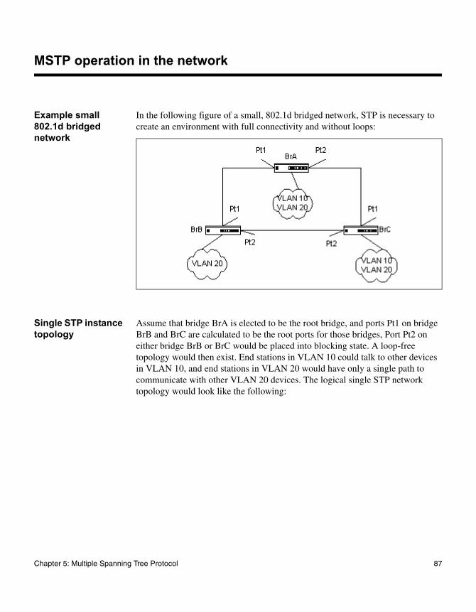
MSTP operation in the network
Example small 802.1d bridged network
In the following figure of a small, 802.1d bridged network, STP is necessary to create an environment with full connectivity and without loops:
Single STP instance topology
Assume that bridge BrA is elected to be the root bridge, and ports Pt1 on bridge BrB and BrC are calculated to be the root ports for those bridges, Port Pt2 on either bridge BrB or BrC would be placed into blocking state. A loop-free topology would then exist. End stations in VLAN 10 could talk to other devices in VLAN 10, and end stations in VLAN 20 would have only a single path to communicate with other VLAN 20 devices. The logical single STP network topology would look like the following:
Chapter 5: Multiple Spanning Tree Protocol 87
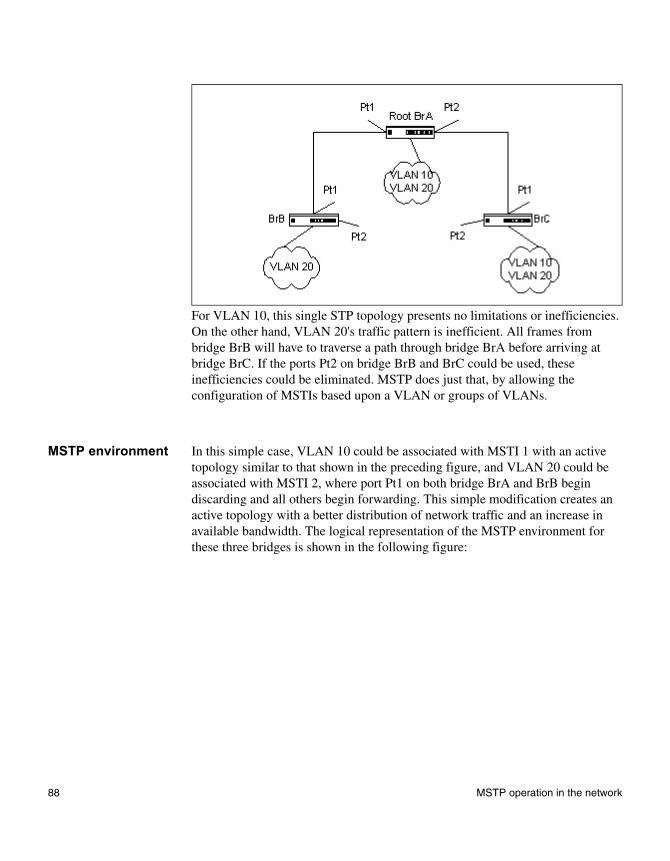
For VLAN 10, this single STP topology presents no limitations or inefficiencies. On the other hand, VLAN 20's traffic pattern is inefficient. All frames from bridge BrB will have to traverse a path through bridge BrA before arriving at bridge BrC. If the ports Pt2 on bridge BrB and BrC could be used, these inefficiencies could be eliminated. MSTP does just that, by allowing the configuration of MSTIs based upon a VLAN or groups of VLANs.
MSTP environment In this simple case, VLAN 10 could be associated with MSTI 1 with an active topology similar to that shown in the preceding figure, and VLAN 20 could be associated with MSTI 2, where port Pt1 on both bridge BrA and BrB begin discarding and all others begin forwarding. This simple modification creates an active topology with a better distribution of network traffic and an increase in available bandwidth. The logical representation of the MSTP environment for these three bridges is shown in the following figure:
88 MSTP operation in the network
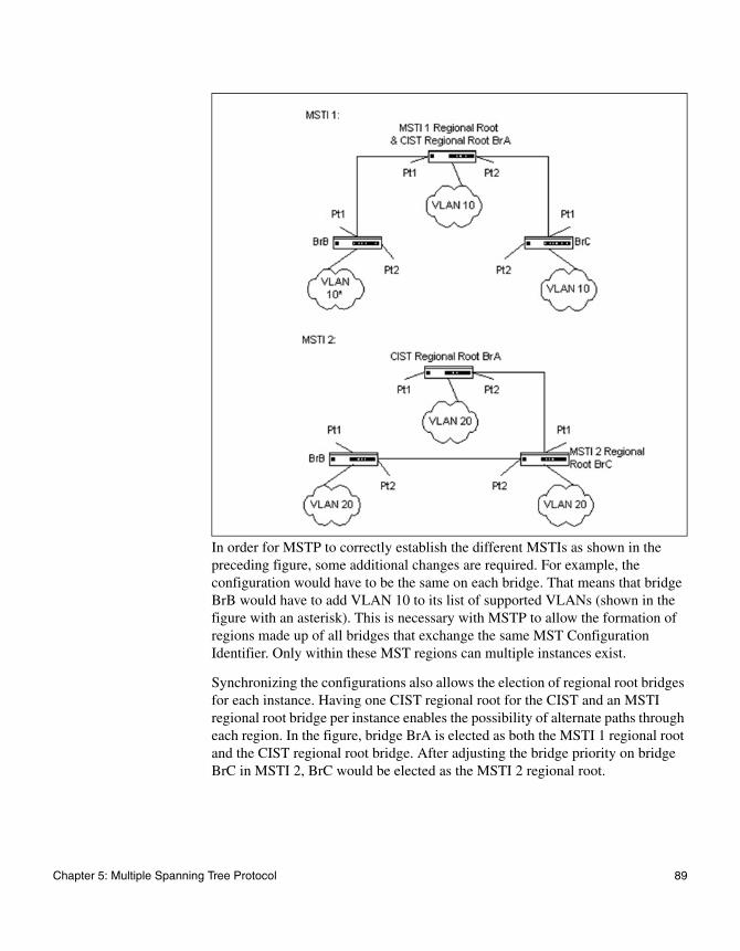
In order for MSTP to correctly establish the different MSTIs as shown in the preceding figure, some additional changes are required. For example, the configuration would have to be the same on each bridge. That means that bridge BrB would have to add VLAN 10 to its list of supported VLANs (shown in the figure with an asterisk). This is necessary with MSTP to allow the formation of regions made up of all bridges that exchange the same MST Configuration Identifier. Only within these MST regions can multiple instances exist.
Synchronizing the configurations also allows the election of regional root bridges for each instance. Having one CIST regional root for the CIST and an MSTI regional root bridge per instance enables the possibility of alternate paths through each region. In the figure, bridge BrA is elected as both the MSTI 1 regional root and the CIST regional root bridge. After adjusting the bridge priority on bridge BrC in MSTI 2, BrC would be elected as the MSTI 2 regional root.
Chapter 5: Multiple Spanning Tree Protocol 89
Multiple MSTP regions
To further illustrate the full connectivity in an MSTP active topology, assume that the following rules apply:
1. Each bridge or LAN is in only one region.
2. Every frame is associated with only one VID.
3. Frames are allocated either to the IST or MSTI within any given region.
4. The IST and each MSTI provides full and simple connectivity between all LANs and bridges in a region.
5. All bridges within a region reach a consistent agreement as to which ports interconnect that region to a different region and label those as boundary ports.
6. At the boundary ports, frames allocated to the CIST or MSTIs are forwarded or not forwarded alike.
7. The CIST provides full and simple connectivity between all LANs and bridges in the network.
Frames with VIDs not allocated to a MSTI will be implicitly assigned to the CIST (or IST within the region) and they will be processed or passed on through the region. For example, in the following figure, VLAN 30 is not explicitly assigned to any instance but it will still, by default, rely on the CIST, since the two bridges define a region (MST region 2). Since the two bridges will process frames internal to region 2, an MSTI regional root bridge must again be elected. In this example, bridge BrA2 is chosen, since it has the lowest external root path cost through a boundary port.
90 MSTP operation in the network
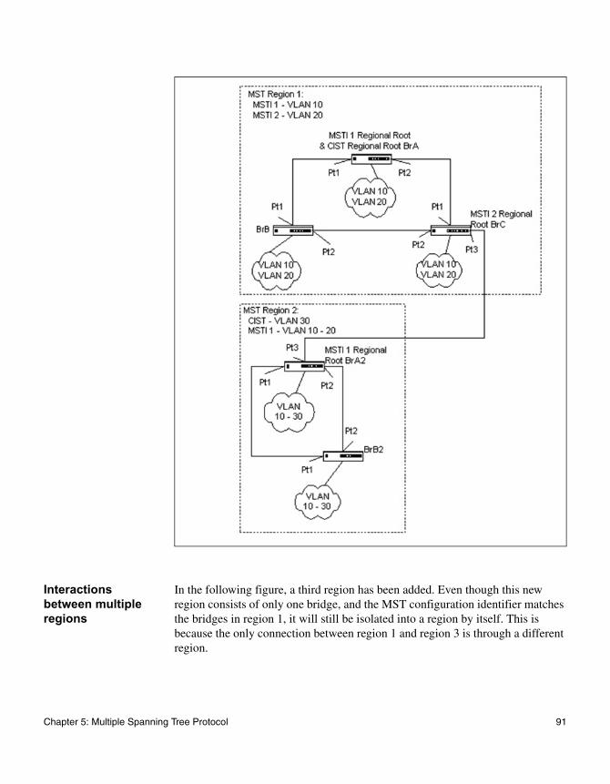
Interactions between multiple regions
In the following figure, a third region has been added. Even though this new region consists of only one bridge, and the MST configuration identifier matches the bridges in region 1, it will still be isolated into a region by itself. This is because the only connection between region 1 and region 3 is through a different region.
Chapter 5: Multiple Spanning Tree Protocol 91
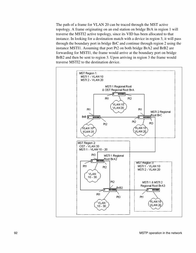
The path of a frame for VLAN 20 can be traced through the MST active topology. A frame originating on an end station on bridge BrA in region 1 will traverse the MSTI2 active topology, since its VID has been allocated to that instance. In looking for a destination match with a device in region 3, it will pass through the boundary port in bridge BrC and continue through region 2 using the instance MSTI1. Assuming that port Pt2 on both bridge BrA2 and BrB2 are forwarding for MSTI1, the frame would arrive at the boundary port on bridge BrB2 and then be sent to region 3. Upon arriving in region 3 the frame would traverse MSTI2 to the destination device.
92 MSTP operation in the network
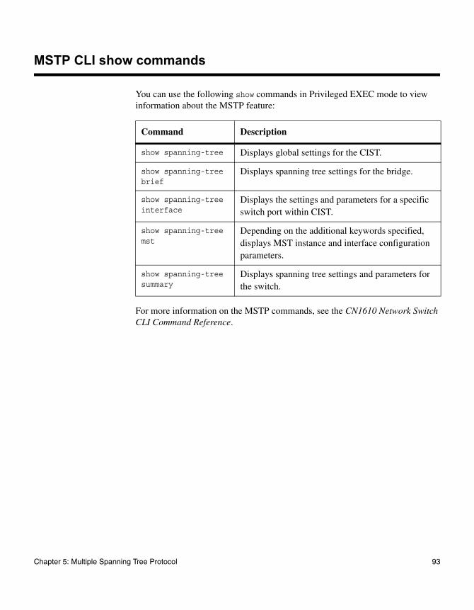
MSTP CLI show commands
You can use the following show commands in Privileged EXEC mode to view information about the MSTP feature:
For more information on the MSTP commands, see the CN1610 Network Switch CLI Command Reference.
Command Description
show spanning-tree Displays global settings for the CIST.
show spanning-tree brief
Displays spanning tree settings for the bridge.
show spanning-tree interface
Displays the settings and parameters for a specific switch port within CIST.
show spanning-tree mst
Depending on the additional keywords specified, displays MST instance and interface configuration parameters.
show spanning-tree summary
Displays spanning tree settings and parameters for the switch.
Chapter 5: Multiple Spanning Tree Protocol 93
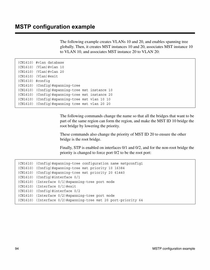
MSTP configuration example
The following example creates VLANs 10 and 20, and enables spanning tree globally. Then, it creates MST instances 10 and 20, associates MST instance 10 to VLAN 10, and associates MST instance 20 to VLAN 20:
The following commands change the name so that all the bridges that want to be part of the same region can form the region, and make the MST ID 10 bridge the root bridge by lowering the priority.
These commands also change the priority of MST ID 20 to ensure the other bridge is the root bridge.
Finally, STP is enabled on interfaces 0/1 and 0/2, and for the non-root bridge the priority is changed to force port 0/2 to be the root port:
(CN1610) #vlan database(CN1610) (Vlan)#vlan 10(CN1610) (Vlan)#vlan 20(CN1610) (Vlan)#exit(CN1610) #config(CN1610) (Config)#spanning-tree(CN1610) (Config)#spanning-tree mst instance 10(CN1610) (Config)#spanning-tree mst instance 20(CN1610) (Config)#spanning-tree mst vlan 10 10(CN1610) (Config)#spanning tree mst vlan 20 20
(CN1610) (Config)#spanning-tree configuration name mstpconfig1(CN1610) (Config)#spanning-tree mst priority 10 16384(CN1610) (Config)#spanning-tree mst priority 20 61440(CN1610) (Config)#interface 0/1(CN1610) (Interface 0/1)#spanning-tree port mode(CN1610) (Interface 0/1)#exit(CN1610) (Config)#interface 0/2(CN1610) (Interface 0/2)#spanning-tree port mode(CN1610) (Interface 0/2)#spanning-tree mst 20 port-priority 64
94 MSTP configuration example
Chapter 6: VLANs
6
VLANsAbout this chapter This chapter describes how to create and manage VLANs on the switch.
Topics in this chapter
This chapter includes the following topics:
◆ “Basic VLAN configuration” on page 96
◆ “Protocol-based VLANs” on page 100
◆ “MAC-based VLANs” on page 104
◆ “IP subnet-based VLANs” on page 106
◆ “Double VLAN tagging” on page 109
95
Basic VLAN configuration
Feature overview In a VLAN, untagged traffic is bridged through specified ports based on the receiving port’s port VLAN ID (PVID). VLANs can help to optimize network traffic patterns because broadcast, multicast, and unknown unicast packets are sent only to ports that are members of the VLAN. Packets that are received with a VLAN tag use that VLAN ID for the switching process.
When a packet enters the switch, it must be associated with a VLAN before the switching logic can be applied. If the packet already contains a VLAN tag, then the specified VLAN ID is used. Otherwise, the PVID associated with the ingress port is used. Each port has an attribute called 'Acceptable Frame Type' that controls whether the port can receive any frame type, or only VLAN-tagged frames. Also, each port has an attribute for ingress filtering. If ingress filtering is enabled, then the receiving port is only allowed to forward the packet on a VLAN if the port itself is a member of that VLAN.
NoteThe supported parameters and defaults may depend on which version of the switch you are using. Not all of the features shown here may work with your configuration.
Operation When a packet arrives at a port, the first port attribute that is checked is the acceptable frame type. If the packet is untagged, but the acceptable frame type setting allows only VLAN-tagged packets to be accepted, then the packet is discarded. If the acceptable frame type setting allows all packets, then the packet is accepted and the port’s PVID is assigned as the packet’s VLAN.
After a packet is associated with a VLAN, then the VLAN is used for the switching process.
The next check is the port’s ingress filtering attribute. If ingress filtering is enabled, and the port is not a member of the VLAN, then the packet is discarded. If ingress filtering is disabled, and the packet is tagged with a VLAN ID that is not defined in the system, then that packet is discarded. Otherwise, the source MAC address is paired with the VLAN ID and searched for in the Layer 2 forwarding database.
96 Basic VLAN configuration
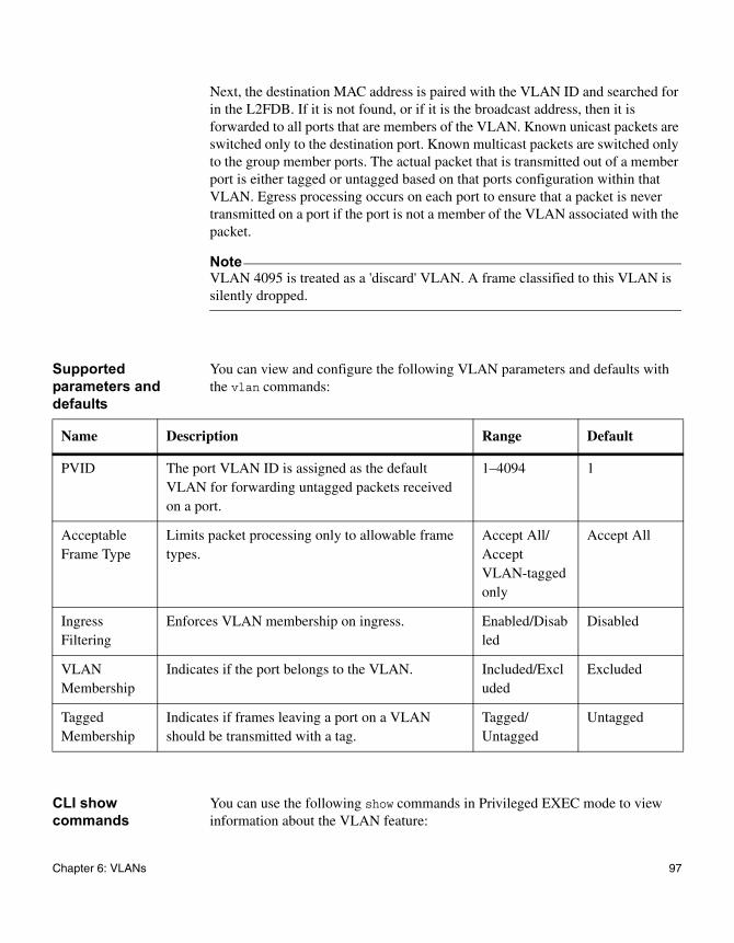
Next, the destination MAC address is paired with the VLAN ID and searched for in the L2FDB. If it is not found, or if it is the broadcast address, then it is forwarded to all ports that are members of the VLAN. Known unicast packets are switched only to the destination port. Known multicast packets are switched only to the group member ports. The actual packet that is transmitted out of a member port is either tagged or untagged based on that ports configuration within that VLAN. Egress processing occurs on each port to ensure that a packet is never transmitted on a port if the port is not a member of the VLAN associated with the packet.
NoteVLAN 4095 is treated as a 'discard' VLAN. A frame classified to this VLAN is silently dropped.
Supported parameters and defaults
You can view and configure the following VLAN parameters and defaults with the vlan commands:
CLI show commands
You can use the following show commands in Privileged EXEC mode to view information about the VLAN feature:
Name Description Range Default
PVID The port VLAN ID is assigned as the default VLAN for forwarding untagged packets received on a port.
1–4094 1
Acceptable Frame Type
Limits packet processing only to allowable frame types.
Accept All/ Accept VLAN-tagged only
Accept All
Ingress Filtering
Enforces VLAN membership on ingress. Enabled/Disabled
Disabled
VLAN Membership
Indicates if the port belongs to the VLAN. Included/Excluded
Excluded
Tagged Membership
Indicates if frames leaving a port on a VLAN should be transmitted with a tag.
Tagged/ Untagged
Untagged
Chapter 6: VLANs 97
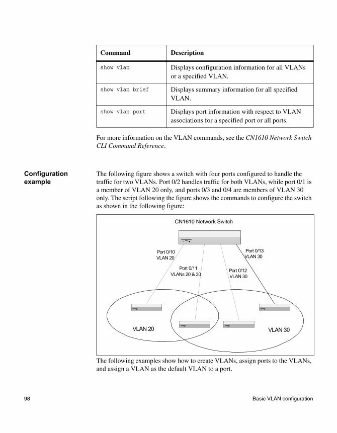
For more information on the VLAN commands, see the CN1610 Network Switch CLI Command Reference.
Configuration example
The following figure shows a switch with four ports configured to handle the traffic for two VLANs. Port 0/2 handles traffic for both VLANs, while port 0/1 is a member of VLAN 20 only, and ports 0/3 and 0/4 are members of VLAN 30 only. The script following the figure shows the commands to configure the switch as shown in the following figure:
The following examples show how to create VLANs, assign ports to the VLANs, and assign a VLAN as the default VLAN to a port.
Command Description
show vlan Displays configuration information for all VLANs or a specified VLAN.
show vlan brief Displays summary information for all specified VLAN.
show vlan port Displays port information with respect to VLAN associations for a specified port or all ports.
Port 0/10VLAN 20
Port 0/11VLANs 20 & 30
Port 0/12VLAN 30
Port 0/13VLAN 30
VLAN 20 VLAN 30
CN1610 Network Switch
98 Basic VLAN configuration
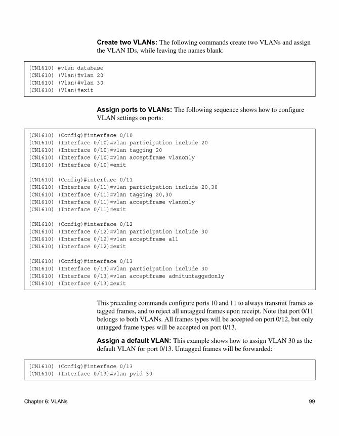
Create two VLANs: The following commands create two VLANs and assign the VLAN IDs, while leaving the names blank:
Assign ports to VLANs: The following sequence shows how to configure VLAN settings on ports:
This preceding commands configure ports 10 and 11 to always transmit frames as tagged frames, and to reject all untagged frames upon receipt. Note that port 0/11 belongs to both VLANs. All frames types will be accepted on port 0/12, but only untagged frame types will be accepted on port 0/13.
Assign a default VLAN: This example shows how to assign VLAN 30 as the default VLAN for port 0/13. Untagged frames will be forwarded:
(CN1610) #vlan database(CN1610) (Vlan)#vlan 20(CN1610) (Vlan)#vlan 30(CN1610) (Vlan)#exit
(CN1610) (Config)#interface 0/10(CN1610) (Interface 0/10)#vlan participation include 20(CN1610) (Interface 0/10)#vlan tagging 20(CN1610) (Interface 0/10)#vlan acceptframe vlanonly(CN1610) (Interface 0/10)#exit
(CN1610) (Config)#interface 0/11(CN1610) (Interface 0/11)#vlan participation include 20,30(CN1610) (Interface 0/11)#vlan tagging 20,30(CN1610) (Interface 0/11)#vlan acceptframe vlanonly(CN1610) (Interface 0/11)#exit
(CN1610) (Config)#interface 0/12(CN1610) (Interface 0/12)#vlan participation include 30(CN1610) (Interface 0/12)#vlan acceptframe all(CN1610) (Interface 0/12)#exit
(CN1610) (Config)#interface 0/13(CN1610) (Interface 0/13)#vlan participation include 30(CN1610) (Interface 0/13)#vlan acceptframe admituntaggedonly(CN1610) (Interface 0/13)#exit
(CN1610) (Config)#interface 0/13(CN1610) (Interface 0/13)#vlan pvid 30
Chapter 6: VLANs 99
Protocol-based VLANs
Feature overview In a protocol-based VLAN, traffic is bridged through specified ports based on the protocol. This feature enables the administrator to define a packet filter that specifies criteria for determining if a packet belongs to a particular VLAN. Protocol-based VLANs are most often used in situations where network segments contain hosts that run multiple protocols.
For example, you could follow these steps to assign NetBEUI and IPX traffic to different ports:
1. Attach a LAN that uses NetBEUI traffic to port 1 on the switch.
2. Attach a LAN that uses IPX traffic to port 2.
3. Attach a router connected to the Internet to port 8.
4. Create an IP VLAN that includes ports 1, 2, and 8.
The NetBEUI traffic on port 1 is not passed to ports 2 or 8. The IPX traffic on port 2 is not passed to ports 1 or 8. However, computers that use the IP protocol can talk freely to ports 1, 2, and 8. This allows the computers to connect to the Internet, while preventing them from receiving traffic that they do not need to see.
Protocol-based VLANs can help optimize network traffic patterns because protocol-specific broadcast messages are sent only to computers that use that protocol.
Operation When a packet enters the switch, the packet is associated with a VLAN. If the packet is tagged, then that VLAN ID is used. If the packet is untagged, then the EtherType is compared to the protocol-based VLAN configuration. If the EtherType is associated with a VLAN, then the packet is assigned to that VLAN. If the EtherType does not match any configured protocols, then the PVID assigned to the port is used.
Supported parameters and defaults
You can use the protocol group command to associate a VLAN ID to a protocol group. You can specify a VLAN ID for the following protocols:
100 Protocol-based VLANs
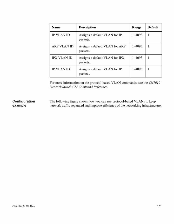
For more information on the protocol-based VLAN commands, see the CN1610 Network Switch CLI Command Reference.
Configuration example
The following figure shows how you can use protocol-based VLANs to keep network traffic separated and improve efficiency of the networking infrastructure:
Name Description Range Default
IP VLAN ID Assigns a default VLAN for IP packets.
1–4093 1
ARP VLAN ID Assigns a default VLAN for ARP packets.
1–4093 1
IPX VLAN ID Assigns a default VLAN for IPX packets.
1–4093 1
IP VLAN ID Assigns a default VLAN for IP packets.
1–4093 1
Chapter 6: VLANs 101
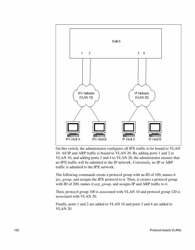
On this switch, the administrator configures all IPX traffic to be bound to VLAN 10. All IP and ARP traffic is bound to VLAN 20. By adding ports 1 and 2 to VLAN 10, and adding ports 3 and 4 to VLAN 20, the administrator ensures that no IPX traffic will be admitted to the IP network. Conversely, no IP or ARP traffic is admitted to the IPX network.
The following commands create a protocol group with an ID of 100, names it ipx_group, and assigns the IPX protocol to it. Then, it creates a protocol group with ID of 200, names it arp_group, and assigns IP and ARP traffic to it.
Then, protocol group 100 is associated with VLAN 10 and protocol group 120 is associated with VLAN 20.
Finally, ports 1 and 2 are added to VLAN 10 and ports 3 and 4 are added to VLAN 20.
102 Protocol-based VLANs
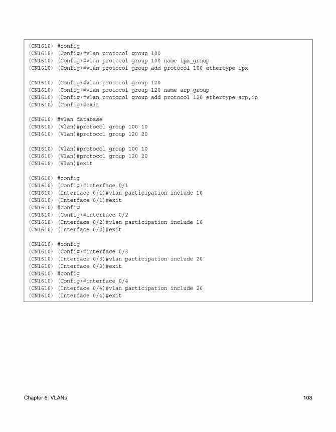
(CN1610) #config(CN1610) (Config)#vlan protocol group 100(CN1610) (Config)#vlan protocol group 100 name ipx_group(CN1610) (Config)#vlan protocol group add protocol 100 ethertype ipx
(CN1610) (Config)#vlan protocol group 120(CN1610) (Config)#vlan protocol group 120 name arp_group(CN1610) (Config)#vlan protocol group add protocol 120 ethertype arp,ip(CN1610) (Config)#exit
(CN1610) #vlan database(CN1610) (Vlan)#protocol group 100 10(CN1610) (Vlan)#protocol group 120 20
(CN1610) (Vlan)#protocol group 100 10(CN1610) (Vlan)#protocol group 120 20(CN1610) (Vlan)#exit
(CN1610) #config(CN1610) (Config)#interface 0/1(CN1610) (Interface 0/1)#vlan participation include 10(CN1610) (Interface 0/1)#exit(CN1610) #config(CN1610) (Config)#interface 0/2(CN1610) (Interface 0/2)#vlan participation include 10(CN1610) (Interface 0/2)#exit
(CN1610) #config(CN1610) (Config)#interface 0/3(CN1610) (Interface 0/3)#vlan participation include 20(CN1610) (Interface 0/3)#exit(CN1610) #config(CN1610) (Config)#interface 0/4(CN1610) (Interface 0/4)#vlan participation include 20(CN1610) (Interface 0/4)#exit
Chapter 6: VLANs 103
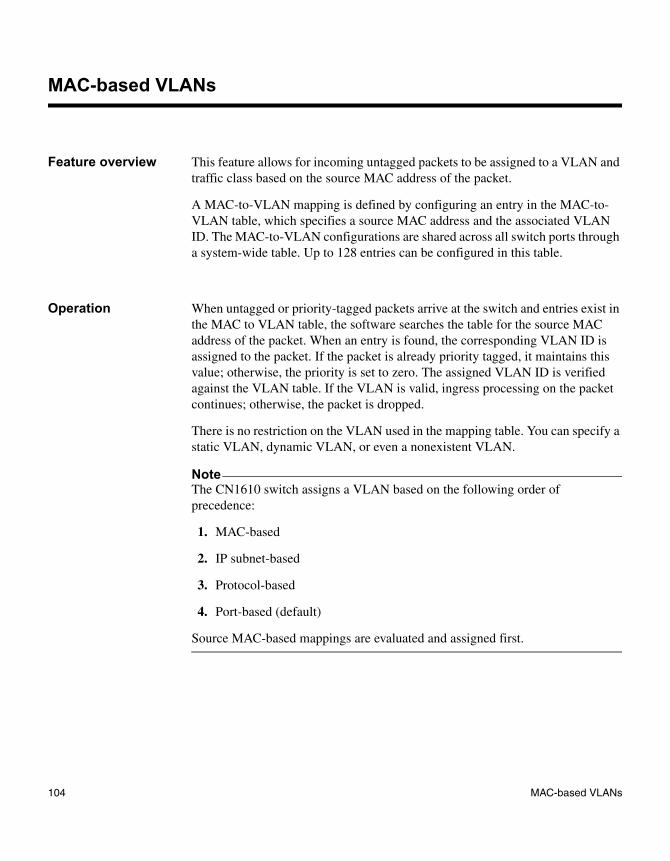
MAC-based VLANs
Feature overview This feature allows for incoming untagged packets to be assigned to a VLAN and traffic class based on the source MAC address of the packet.
A MAC-to-VLAN mapping is defined by configuring an entry in the MAC-to-VLAN table, which specifies a source MAC address and the associated VLAN ID. The MAC-to-VLAN configurations are shared across all switch ports through a system-wide table. Up to 128 entries can be configured in this table.
Operation When untagged or priority-tagged packets arrive at the switch and entries exist in the MAC to VLAN table, the software searches the table for the source MAC address of the packet. When an entry is found, the corresponding VLAN ID is assigned to the packet. If the packet is already priority tagged, it maintains this value; otherwise, the priority is set to zero. The assigned VLAN ID is verified against the VLAN table. If the VLAN is valid, ingress processing on the packet continues; otherwise, the packet is dropped.
There is no restriction on the VLAN used in the mapping table. You can specify a static VLAN, dynamic VLAN, or even a nonexistent VLAN.
NoteThe CN1610 switch assigns a VLAN based on the following order of precedence:
1. MAC-based
2. IP subnet-based
3. Protocol-based
4. Port-based (default)
Source MAC-based mappings are evaluated and assigned first.
104 MAC-based VLANs
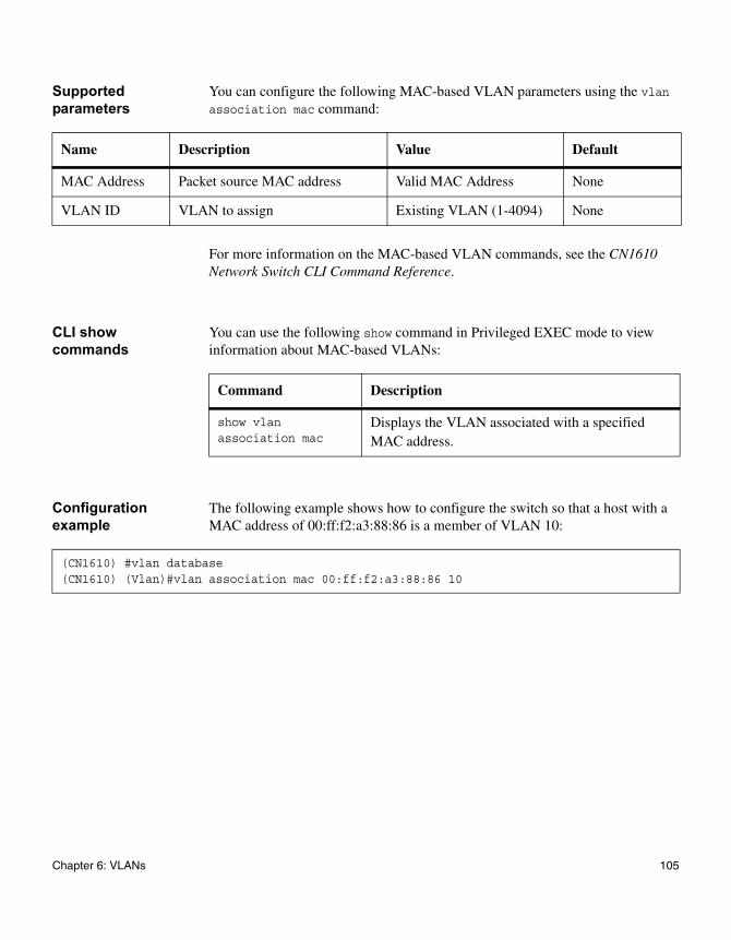
Supported parameters
You can configure the following MAC-based VLAN parameters using the vlan association mac command:
For more information on the MAC-based VLAN commands, see the CN1610 Network Switch CLI Command Reference.
CLI show commands
You can use the following show command in Privileged EXEC mode to view information about MAC-based VLANs:
Configuration example
The following example shows how to configure the switch so that a host with a MAC address of 00:ff:f2:a3:88:86 is a member of VLAN 10:
Name Description Value Default
MAC Address Packet source MAC address Valid MAC Address None
VLAN ID VLAN to assign Existing VLAN (1-4094) None
Command Description
show vlan association mac
Displays the VLAN associated with a specified MAC address.
(CN1610) #vlan database(CN1610) (Vlan)#vlan association mac 00:ff:f2:a3:88:86 10
Chapter 6: VLANs 105
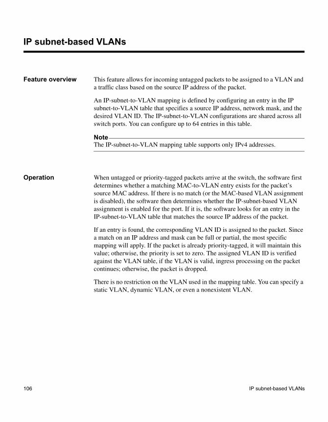
IP subnet-based VLANs
Feature overview This feature allows for incoming untagged packets to be assigned to a VLAN and a traffic class based on the source IP address of the packet.
An IP-subnet-to-VLAN mapping is defined by configuring an entry in the IP subnet-to-VLAN table that specifies a source IP address, network mask, and the desired VLAN ID. The IP-subnet-to-VLAN configurations are shared across all switch ports. You can configure up to 64 entries in this table.
NoteThe IP-subnet-to-VLAN mapping table supports only IPv4 addresses.
Operation When untagged or priority-tagged packets arrive at the switch, the software first determines whether a matching MAC-to-VLAN entry exists for the packet’s source MAC address. If there is no match (or the MAC-based VLAN assignment is disabled), the software then determines whether the IP-subnet-based VLAN assignment is enabled for the port. If it is, the software looks for an entry in the IP-subnet-to-VLAN table that matches the source IP address of the packet.
If an entry is found, the corresponding VLAN ID is assigned to the packet. Since a match on an IP address and mask can be full or partial, the most specific mapping will apply. If the packet is already priority-tagged, it will maintain this value; otherwise, the priority is set to zero. The assigned VLAN ID is verified against the VLAN table, if the VLAN is valid, ingress processing on the packet continues; otherwise, the packet is dropped.
There is no restriction on the VLAN used in the mapping table. You can specify a static VLAN, dynamic VLAN, or even a nonexistent VLAN.
106 IP subnet-based VLANs

NoteThe CN1610 switch assigns a VLAN based on the following order of precedence:
1. MAC-based
2. IP subnet-based
3. Protocol-based
4. Port-based (default)
Source MAC-based mappings are evaluated and assigned first.
Supported parameters and defaults
You can use the vlan association subnet command to view and configure the following IP subnet-based VLAN parameters:
For more information on the IP-subnet-based VLAN commands, see the CN1610 Network Switch CLI Command Reference.
CLI show commands
You can use the following show command in Privileged EXEC mode to view information about IP subnet-based VLANs:
Name Description Value Default
IP Address Packet source IP address Valid IP address format
None
Network Mask Packet source IP subnet mask Valid IP address format
None
VLAN ID VLAN to assign Existing VLAN (1-4094)
None
Command Description
show vlan association subnet
Displays the VLAN associated with a specified IP address and net mask.
Chapter 6: VLANs 107

Configuration example
This example configures the switch so that all hosts with IP addresses in the 192.168.25.0/24 network are members of VLAN 10:
(CN1610) #vlan database(CN1610) (Vlan)#vlan association subnet 192.168.25.0 255.255.255.0 10
108 IP subnet-based VLANs
Double VLAN tagging
Feature overview The use of virtual metropolitan area networks (MANs) enables passing VLAN traffic from one customer domain to another through a metro core in a simple and cost-effective manner. An additional VLAN tag is used to differentiate customers in the MAN while preserving individual customers’ VLAN identification when they enter their own 802.1Q domains. With the introduction of this second tag, customers are no longer required to divide the 4k VLAN ID space to send traffic on an Ethernet-based MAN.
Double VLAN tag To differentiate customers in the MAN core, a tag is added to every frame. The format of the tag is identical to the 802.1Q VLAN tag, resulting in the term double VLAN tagging (or nested/stacked VLAN tagging). The DVLAN tag adds 4 bytes to the packet.
The format of the second tag is similar to the 802.1Q VLAN tag. In short, it has 2 bytes for the EtherType, 4 bits for the priority and CFI bit, and the remaining 12 bits for a customer ID.
Access and uplink ports
Double VLAN tagging categorizes each port as either an access port or an uplink port. When the mode dvlan-tunnel command is executed on an interface, it becomes an uplink port. At that point, all other ports are considered to be access ports. Any additional port on which the mode dvlan-tunnel command is executed will also become an uplink port. The typical configuration and operation works as shown in the following figure:
Chapter 6: VLANs 109
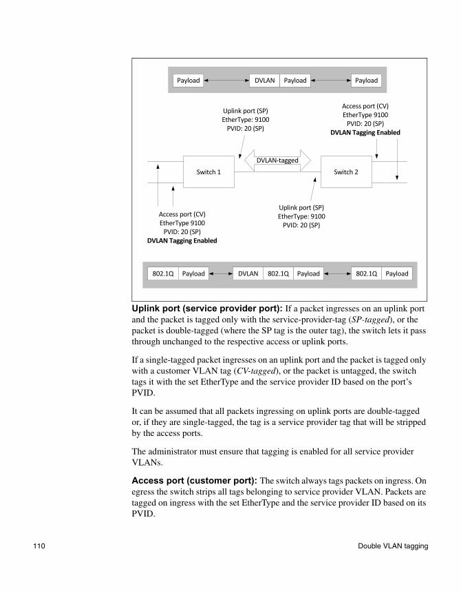
Uplink port (service provider port): If a packet ingresses on an uplink port and the packet is tagged only with the service-provider-tag (SP-tagged), or the packet is double-tagged (where the SP tag is the outer tag), the switch lets it pass through unchanged to the respective access or uplink ports.
If a single-tagged packet ingresses on an uplink port and the packet is tagged only with a customer VLAN tag (CV-tagged), or the packet is untagged, the switch tags it with the set EtherType and the service provider ID based on the port’s PVID.
It can be assumed that all packets ingressing on uplink ports are double-tagged or, if they are single-tagged, the tag is a service provider tag that will be stripped by the access ports.
The administrator must ensure that tagging is enabled for all service provider VLANs.
Access port (customer port): The switch always tags packets on ingress. On egress the switch strips all tags belonging to service provider VLAN. Packets are tagged on ingress with the set EtherType and the service provider ID based on its PVID.
Payload DVLAN Payload Payload
Uplink port (SP)EtherType: 9100
PVID: 20 (SP)
Access port (CV)EtherType 9100
PVID: 20 (SP)DVLAN Tagging Enabled
DVLAN-tagged
Switch 1 Switch 2
Uplink port (SP)EtherType: 9100
PVID: 20 (SP)Access port (CV)EtherType 9100
PVID: 20 (SP)DVLAN Tagging Enabled
802.1Q DVLAN Payload PayloadPayload 802.1Q 802.1Q
110 Double VLAN tagging
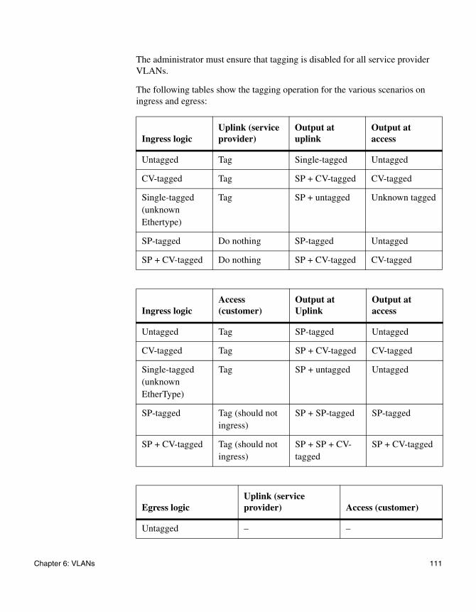
The administrator must ensure that tagging is disabled for all service provider VLANs.
The following tables show the tagging operation for the various scenarios on ingress and egress:
Ingress logicUplink (service provider)
Output at uplink
Output at access
Untagged Tag Single-tagged Untagged
CV-tagged Tag SP + CV-tagged CV-tagged
Single-tagged (unknown Ethertype)
Tag SP + untagged Unknown tagged
SP-tagged Do nothing SP-tagged Untagged
SP + CV-tagged Do nothing SP + CV-tagged CV-tagged
Ingress logicAccess (customer)
Output at Uplink
Output at access
Untagged Tag SP-tagged Untagged
CV-tagged Tag SP + CV-tagged CV-tagged
Single-tagged (unknown EtherType)
Tag SP + untagged Untagged
SP-tagged Tag (should not ingress)
SP + SP-tagged SP-tagged
SP + CV-tagged Tag (should not ingress)
SP + SP + CV- tagged
SP + CV-tagged
Egress logicUplink (service provider) Access (customer)
Untagged – –
Chapter 6: VLANs 111
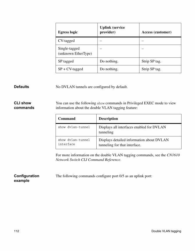
Defaults No DVLAN tunnels are configured by default.
CLI show commands
You can use the following show commands in Privileged EXEC mode to view information about the double VLAN tagging feature:
For more information on the double VLAN tagging commands, see the CN1610 Network Switch CLI Command Reference.
Configuration example
The following commands configure port 0/5 as an uplink port:
CV-tagged – –
Single-tagged (unknown EtherType)
– –
SP tagged Do nothing. Strip SP tag.
SP + CV-tagged Do nothing. Strip SP tag.
Egress logicUplink (service provider) Access (customer)
Command Description
show dvlan-tunnel Displays all interfaces enabled for DVLAN tunneling
show dvlan-tunnel interface
Displays detailed information about DVLAN tunneling for that interface.
112 Double VLAN tagging
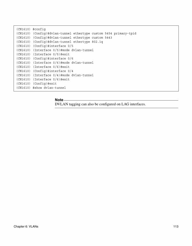
NoteDVLAN tagging can also be configured on LAG interfaces.
(CN1610) #config(CN1610) (Config)#dvlan-tunnel ethertype custom 5454 primary-tpid(CN1610) (Config)#dvlan-tunnel ethertype custom 5443(CN1610) (Config)#dvlan-tunnel ethertype 802.1q(CN1610) (Config)#interface 0/5(CN1610) (Interface 0/5)#mode dvlan-tunnel(CN1610) (Interface 0/5)#exit(CN1610) (Config)#interface 0/6(CN1610) (Interface 0/6)#mode dvlan-tunnel(CN1610) (Interface 0/6)#exit(CN1610) (Config)#interface 0/4(CN1610) (Interface 0/4)#mode dvlan-tunnel(CN1610) (Interface 0/6)#exit(CN1610) (Config)#exit(CN1610) #show dvlan-tunnel
Chapter 6: VLANs 113

114 Double VLAN tagging
Chapter 7: Quality of Service
7
Quality of ServiceAbout this chapter The CN1610 FASTPATH software provides the following quality of service (QoS) features that help to ensure optimal handling of traffic:
◆ Class of Service (CoS) Queue Mapping—This feature allows traffic to be classified into streams and given certain QoS treatment in accordance with defined per-hop behaviors.
◆ CoS Queue Configuration—This feature enables you to directly configure certain aspects of device queueing to provide the desired QoS behavior for different types of network traffic. The priority of a packet arriving at an interface can be used to steer the packet to the appropriate outbound CoS queue through a mapping table. You can configure CoS queue characteristics such as minimum guaranteed bandwidth, and transmission rate shaping, at the queue (or port) level.
◆ Differentiated Services (DiffServ)—This feature enables you to classify traffic into streams and given certain QoS treatment in accordance with defined per-hop behaviors.
Topics in this chapter
This chapter includes the following topics:
◆ “Class of service (CoS) queue mapping” on page 116
◆ “CoS queue configuration” on page 119
◆ “QoS map and queue configuration example” on page 120
◆ “Differentiated services (DiffServ)” on page 123
115
Class of service (CoS) queue mapping
CoS overview In a typical switch or router, each physical port consists of one or more queues for transmitting packets on the attached network. Multiple queues per port are often provided to give preference to certain packets over others based on user-defined criteria. When a packet is queued for transmission in a port, the rate at which it is serviced depends on how the queue is configured and, possibly, the amount of traffic present in the other queues of the port. If a delay is necessary, packets are held in the queue until the scheduler authorizes the queue for transmission. As queues become full, packets have no place to be held for transmission and are dropped by the device.
CoS queue mapping
Incoming packets can be mapped to a CoS queue based on port configuration and characteristics of the packets themselves.
CoS queue mapping uses the concepts of trusted and untrusted ports:
Trusted ports: A trusted port is one that takes at face value a certain priority designation within arriving packets. Specifically, a port can be configured to trust one of the following packet fields:
◆ 802.1p user priority
◆ IP precedence (which may not be supported on newer hardware)
◆ IP DSCP
Packets arriving at the port ingress are inspected and their trusted field value is used to designate the CoS queue that the packet is placed in when forwarded to the appropriate egress port. A mapping table associates the trusted field value with the desired CoS queue. If the port is configured to trust the 802.1p user priority, but the packet does not have a priority tag, then the default port priority is assigned to the packet. The port priority defaults to zero.
Untrusted ports: Alternatively, a port can be configured as untrusted, whereby it does not trust any incoming packet priority designation and uses the port default priority value instead. The port priority defaults to zero. All packets arriving at the ingress of an untrusted port are directed to a specific CoS queue on the appropriate egress port(s) in accordance with the configured default priority of the ingress port. This process is also used when the switch cannot honor a trusted port mapping, such as when a non-IP packet arrives at a port configured to trust the IP precedence value.
116 Class of service (CoS) queue mapping
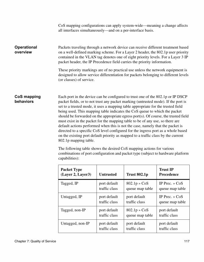
CoS mapping configurations can apply system-wide—meaning a change affects all interfaces simultaneously—and on a per-interface basis.
Operational overview
Packets traveling through a network device can receive different treatment based on a well-defined marking scheme. For a Layer 2 header, the 802.1p user priority contained in the VLAN tag denotes one of eight priority levels. For a Layer 3 IP packet header, the IP Precedence field carries the priority information.
These priority markings are of no practical use unless the network equipment is designed to allow service differentiation for packets belonging to different levels (or classes) of service.
CoS mapping behaviors
Each port in the device can be configured to trust one of the 802.1p or IP DSCP packet fields, or to not trust any packet marking (untrusted mode). If the port is set to a trusted mode, it uses a mapping table appropriate for the trusted field being used. This mapping table indicates the CoS queue to which the packet should be forwarded on the appropriate egress port(s). Of course, the trusted field must exist in the packet for the mapping table to be of any use, so there are default actions performed when this is not the case, namely that the packet is directed to a specific CoS level configured for the ingress port as a whole based on the existing port default priority as mapped to a traffic class by the current 802.1p mapping table.
The following table shows the desired CoS mapping actions for various combinations of port configuration and packet type (subject to hardware platform capabilities):
Packet Type (Layer 2, Layer3) Untrusted Trust 802.1p
Trust IP Precedence
Tagged, IP port default traffic class
802.1p » CoS queue map table
IP Prec. » CoS queue map table
Untagged, IP port default traffic class
port default traffic class
IP Prec. » CoS queue map table
Tagged, non-IP port default traffic class
802.1p » CoS queue map table
port default traffic class
Untagged, non-IP port default traffic class
port default traffic class
port default traffic class
Chapter 7: Quality of Service 117
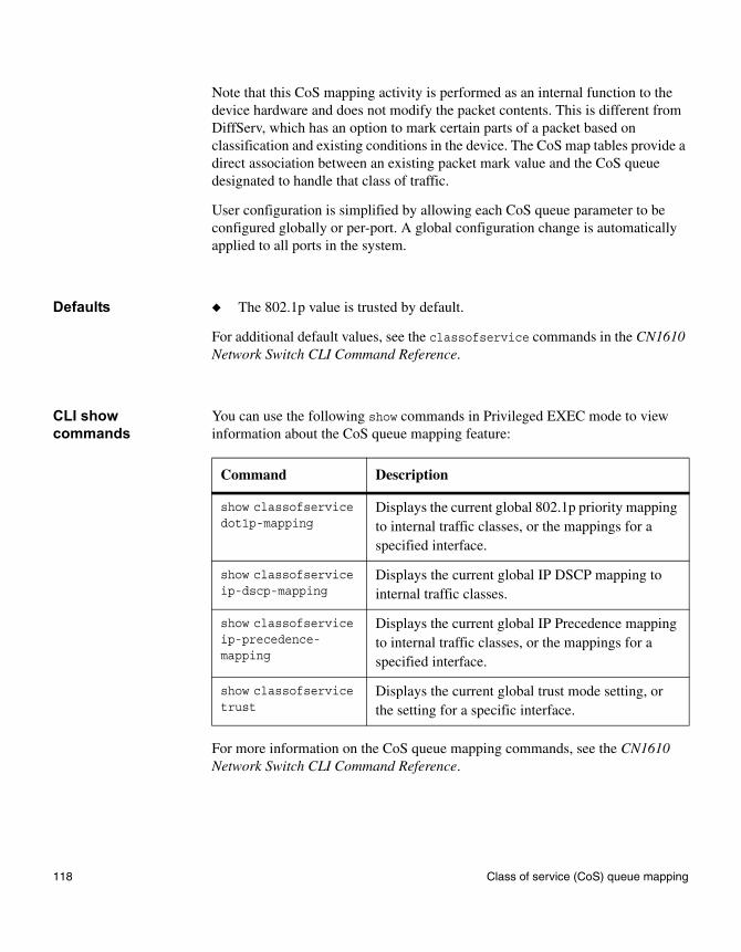
Note that this CoS mapping activity is performed as an internal function to the device hardware and does not modify the packet contents. This is different from DiffServ, which has an option to mark certain parts of a packet based on classification and existing conditions in the device. The CoS map tables provide a direct association between an existing packet mark value and the CoS queue designated to handle that class of traffic.
User configuration is simplified by allowing each CoS queue parameter to be configured globally or per-port. A global configuration change is automatically applied to all ports in the system.
Defaults ◆ The 802.1p value is trusted by default.
For additional default values, see the classofservice commands in the CN1610 Network Switch CLI Command Reference.
CLI show commands
You can use the following show commands in Privileged EXEC mode to view information about the CoS queue mapping feature:
For more information on the CoS queue mapping commands, see the CN1610 Network Switch CLI Command Reference.
Command Description
show classofservice dot1p-mapping
Displays the current global 802.1p priority mapping to internal traffic classes, or the mappings for a specified interface.
show classofservice ip-dscp-mapping
Displays the current global IP DSCP mapping to internal traffic classes.
show classofservice ip-precedence-mapping
Displays the current global IP Precedence mapping to internal traffic classes, or the mappings for a specified interface.
show classofservice trust
Displays the current global trust mode setting, or the setting for a specific interface.
118 Class of service (CoS) queue mapping

CoS queue configuration
Configuration overview
The egress queues of a port contain various operational attributes that you can configure to give the desired service level.
You can control the amount of bandwidth used by the queue, the queue depth during times of congestion, and the scheduling of packet transmission from the set of all queues on a port. Each port has its own set of CoS queue-related configuration.
Each CoS queue parameter can be configured globally or on a per-port basis. Global configuration changes are automatically applied to all ports in the system. Defining these on a per-queue basis allows the user to create the desired service characteristics for different types of traffic.
Defaults See the CN1610 Network Switch CLI Command Reference for the configurable queue parameters and their default values,
CLI show commands
You can use the following show command in Privileged EXEC mode to view information about the CoS queue configuration feature:
For more information on the CoS queue configuration commands, see the CN1610 Network Switch CLI Command Reference.
Command Description
show interfaces cos-queue
Displays the global class-of-service queue configuration, or the configuration for a specified interface.
Chapter 7: Quality of Service 119
QoS map and queue configuration example
Description This example illustrates the network operation as it relates to CoS mapping and queue configuration.
Four packets are presented to the ingress port 0/10 in the order A, B, C, then D. Port 10 is designated to trust the 802.1p field of the packet, which serves to direct packets A, B, and D to their respective queues on the egress port. These three packets utilize the 802.1p to CoS queue map table configured for port 0/10. In this case, the 802.1p user priority 3 has been set up to send the packet to queue 6 instead of the default queue 3. Since packet C does not contain a VLAN tag, the 802.1p user priority does not exist, so port 0/10 relies on its default port priority 2 to direct packet C to egress queue 1 (the 802.1p mapping table is always used for this translation).
The egress port 0/8 in this example is configured with strict priority on queue 7 and a weighted scheduling scheme for queues 6-0. Assuming queue 6 has a higher weighting than queue 1 (the relative weight values shown as a percentage, with 0 percent indicating that the bandwidth is not guaranteed), the queue service order is 7, followed by 6, followed by 1. Assuming each queue unloads all packets shown in the figure, the packet transmission order as seen on the network leading out of port x is B, A, D, C. Thus, packet B, with its higher user precedence than the others, is able to work its way through the device with minimal delay and is transmitted ahead of the other packets at the egress port.
120 QoS map and queue configuration example
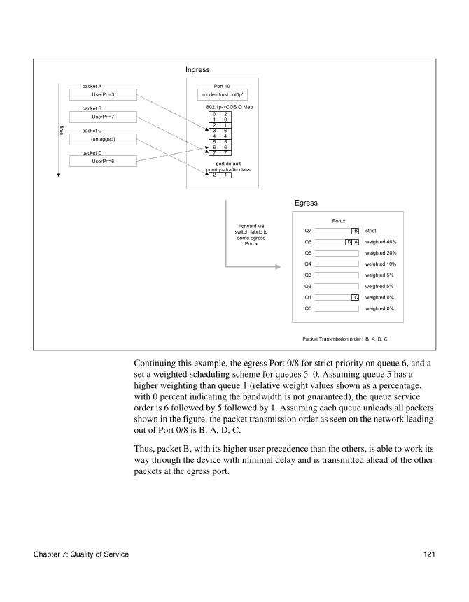
Continuing this example, the egress Port 0/8 for strict priority on queue 6, and a set a weighted scheduling scheme for queues 5–0. Assuming queue 5 has a higher weighting than queue 1 (relative weight values shown as a percentage, with 0 percent indicating the bandwidth is not guaranteed), the queue service order is 6 followed by 5 followed by 1. Assuming each queue unloads all packets shown in the figure, the packet transmission order as seen on the network leading out of Port 0/8 is B, A, D, C.
Thus, packet B, with its higher user precedence than the others, is able to work its way through the device with minimal delay and is transmitted ahead of the other packets at the egress port.
UserPri=3
packet A
UserPri=7
packet B
(untagged)
packet C
UserPri=6
packet D
time
Port 10
mode='trust dot1p'
0 21 02 13 64 45 56 67 7
802.1p->COS Q Map
port default priority->traffic class
Port x
ADQ6
BQ7
Q5
strict
weighted 40%
weighted 20%
Q4 weighted 10%
Q3 weighted 5%
Q2 weighted 5%
CQ1
Q0
weighted 0%
weighted 0%
Forward via switch fabric to some egress
Port x
Ingress
Egress
Packet Transmission order: B, A, D, C
2 1
Chapter 7: Quality of Service 121
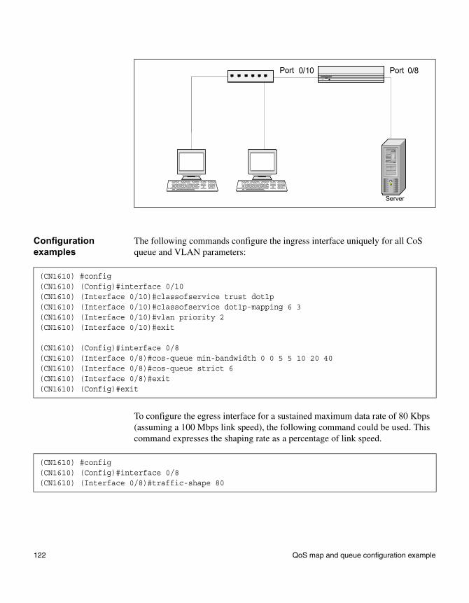
Configuration examples
The following commands configure the ingress interface uniquely for all CoS queue and VLAN parameters:
To configure the egress interface for a sustained maximum data rate of 80 Kbps (assuming a 100 Mbps link speed), the following command could be used. This command expresses the shaping rate as a percentage of link speed.
Server
Port 0/10 Port 0/8
(CN1610) #config(CN1610) (Config)#interface 0/10(CN1610) (Interface 0/10)#classofservice trust dot1p(CN1610) (Interface 0/10)#classofservice dot1p-mapping 6 3(CN1610) (Interface 0/10)#vlan priority 2(CN1610) (Interface 0/10)#exit
(CN1610) (Config)#interface 0/8(CN1610) (Interface 0/8)#cos-queue min-bandwidth 0 0 5 5 10 20 40(CN1610) (Interface 0/8)#cos-queue strict 6(CN1610) (Interface 0/8)#exit(CN1610) (Config)#exit
(CN1610) #config(CN1610) (Config)#interface 0/8(CN1610) (Interface 0/8)#traffic-shape 80
122 QoS map and queue configuration example
Differentiated services (DiffServ)
Feature overview The QoS feature contains differentiated services (DiffServ) support, whereby traffic is classified into streams and given certain QoS treatment in accordance with defined per-hop behaviors.
Standard IP-based networks are designed to provide “best effort” data delivery service. Best effort service implies that the network delivers the data in a timely fashion, although there is no guarantee that it will. During times of congestion, packets may be delayed, sent sporadically, or dropped. For typical Internet applications, such as email and file transfer, a slight degradation in service is acceptable and in many cases unnoticeable. Conversely, any degradation of service has undesirable effects on applications with strict timing requirements, such as voice or multimedia.
Configuration overview
DiffServ configuration involves the following steps:
1. Create classes and define class criteria. A class consists of a set of rules that identify which packets belong to the class. Inbound traffic is separated into traffic classes based on Layer 2, Layer 3, and Layer 4 header data. Every match criterion defined for the class must be true for a match to occur.
2. Create policies, associate classes with policies, and define policy statements. A policy defines the QoS attributes for one or more traffic classes. An example of an attribute is the ability to mark a packet at ingress. The CN1610 switch supports the ability to assign traffic classes to output CoS queues, and to mirror incoming packets in a traffic stream to a specific egress interface (physical port or LAG).
A policy can contain multiples classes. The actions taken depend on which class matches the packet.
3. Create a DiffServ service instance by adding a policy to an inbound interface.
Class match criteria When you create a class, you configure one or more conditions that together serve as criteria for the match. In order for a packet to be considered a match, it must meet all the criteria. These conditions include the following:
◆ The packet’s class-of-service value (primary or secondary).
Chapter 7: Quality of Service 123
◆ The packet’s source or destination MAC or IP address.
◆ The packet’s source or destination Layer 4 (TCP or UDP) port number.
◆ The packet’s EtherType value.
◆ The packet’s IP precedence, IP DSCP, or ToS value.
◆ The packet’s protocol number (that is, the IANA logical port number).
◆ The packet’s VLAN (primary or secondary).
Additionally, you can specify a condition where all packets match the class and no further conditions are specified.
Policy actions You can configure a policy to take the following actions when incoming packets match a class that is associated to the policy:
◆ Configure the egress queue to which the packets are assigned.
◆ Set the policing color conform mode for the packets. Color conform mode requires the existence of one or more color classes that are valid for use with this policy instance. A valid color class contains a single match criterion for one of the following fields (provided the field does not conflict with the classifier of the policy instance itself):
❖ CoS
❖ IP DSCP
❖ IP Precedence
❖ Secondary CoS
◆ Specify that all packets are to be dropped.
◆ Mark the packets with the an 802.1p CoS, IP Precedence, or IP DSCP value.
◆ Specify that all incoming packets are to be either mirrored or redirected to a particular port.
◆ Apply a policing action to the packets. Two policing types are available: simple and two-rate:
❖ Simple traffic policing compares a single data rate and burst size (conforming), resulting in two outcomes (conform and violate).
❖ Two-rate traffic policing uses two data rate and burst size parameters (conforming and peak), resulting in three outcomes: conform, exceed, and violate. The conforming and peak burst size parameters are specified in kilobytes (KB) and are integers from 1 to 128.
When packets conform to the policing metrics one of the following actions is taken:
❖ Drop—The packets are immediately dropped.
124 Differentiated services (DiffServ)
❖ Mark CoS—The packets are marked by DiffServ with the specified CoS value before being presented to the system forwarding element. This selection requires that the Mark CoS value field be set.
❖ Mark CoS as Secondary CoS—For double-tagged packets, the 802.1p tag is marked by DiffServ with the (original) 802.1p value of the inner tag before the packet is presented to the system forwarding element.
❖ Mark IP DSCP—The packets are marked by DiffServ with the specified DSCP value before being presented to the system forwarding element. This selection requires the DSCP value field to be set.
❖ Mark IP Precedence—The packets are marked by DiffServ with the specified IP Precedence value before being presented to the system forwarding element. This selection requires that the Mark IP Precedence value field be set.
❖ Send—The packets are presented unmodified by DiffServ to the system forwarding element.
The default is action is Send.
◆ Specify all incoming packets are to be redirected to another interface.
Defaults No DiffServ configuration is present by default.
CLI show commands
You can use the following show commands in Privileged EXEC mode to view information about the DiffServ feature:
Command Description
show class-map Lists the currently configured classes and their class criteria,
show policy-map Lists the currently configured policies and the classes that are assigned to them.
show policy-map interface interface in
show policy-map interface interface out
Lists the currently configured inbound or outbound policies that are enabled on the specified interface.
show service-policy Displays the currently configured service policies.
Chapter 7: Quality of Service 125
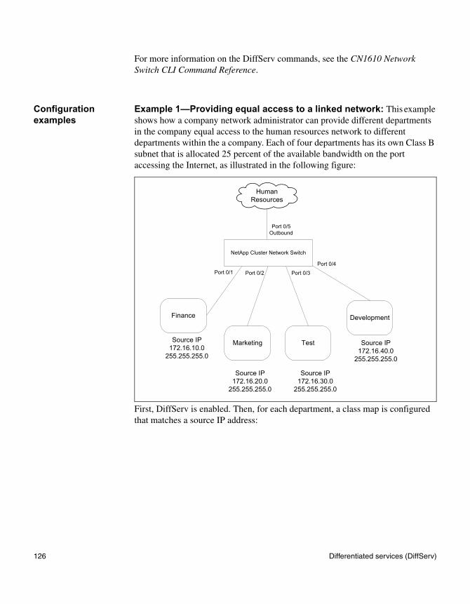
For more information on the DiffServ commands, see the CN1610 Network Switch CLI Command Reference.
Configuration examples
Example 1—Providing equal access to a linked network: This example shows how a company network administrator can provide different departments in the company equal access to the human resources network to different departments within the a company. Each of four departments has its own Class B subnet that is allocated 25 percent of the available bandwidth on the port accessing the Internet, as illustrated in the following figure:
First, DiffServ is enabled. Then, for each department, a class map is configured that matches a source IP address:
Finance
Marketing Test
Development
Source IP172.16.10.0
255.255.255.0
Source IP172.16.20.0
255.255.255.0
Source IP172.16.30.0
255.255.255.0
Source IP172.16.40.0
255.255.255.0
Human Resources
NetApp Cluster Network Switch
Port 0/5 Outbound
Port 0/1 Port 0/2 Port 0/3
Port 0/4
126 Differentiated services (DiffServ)
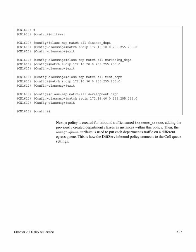
Next, a policy is created for inbound traffic named internet_access, adding the previously created department classes as instances within this policy. Then, the assign-queue attribute is used to put each department's traffic on a different egress queue. This is how the DiffServ inbound policy connects to the CoS queue settings.
(CN1610) #(CN1610) (config)#diffserv
(CN1610) (config)#class-map match-all finance_dept(CN1610) (Config-classmap)#match srcip 172.16.10.0 255.255.255.0(CN1610) (Config-classmap)#exit
(CN1610) (Config-classmap)#class-map match-all marketing_dept(CN1610) (config)#match srcip 172.16.20.0 255.255.255.0(CN1610) (Config-classmap)#exit
(CN1610) (Config-classmap)#class-map match-all test_dept(CN1610) (config)#match srcip 172.16.30.0 255.255.255.0(CN1610) (Config-classmap)#exit
(CN1610) (config)#class-map match-all development_dept(CN1610) (Config-classmap)#match srcip 172.16.40.0 255.255.255.0(CN1610) (Config-classmap)#exit
(CN1610) (config)#
Chapter 7: Quality of Service 127
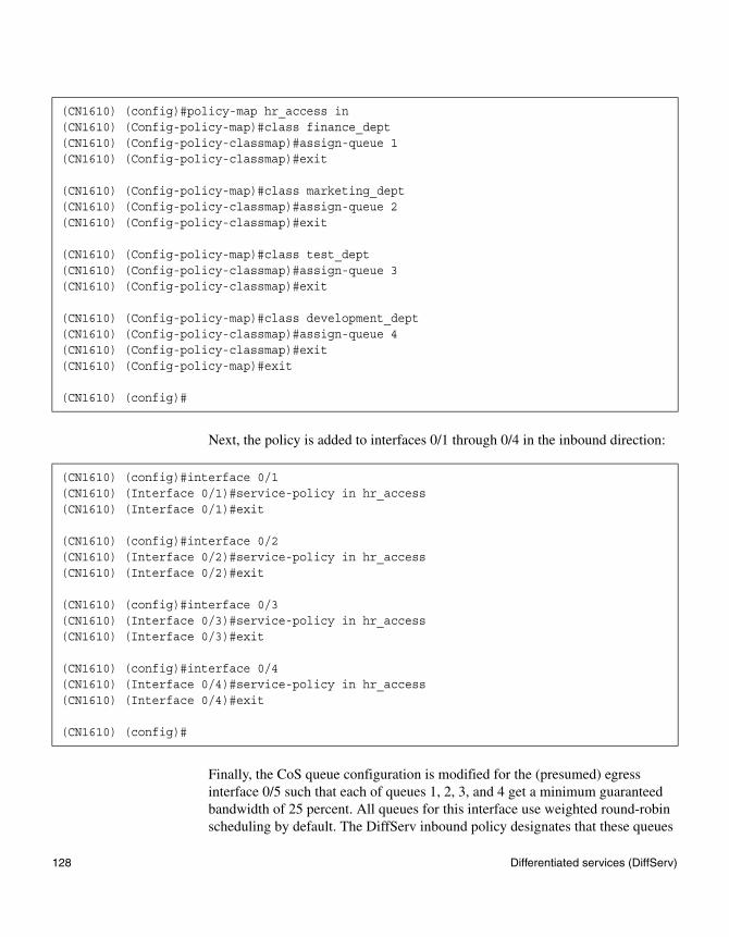
Next, the policy is added to interfaces 0/1 through 0/4 in the inbound direction:
Finally, the CoS queue configuration is modified for the (presumed) egress interface 0/5 such that each of queues 1, 2, 3, and 4 get a minimum guaranteed bandwidth of 25 percent. All queues for this interface use weighted round-robin scheduling by default. The DiffServ inbound policy designates that these queues
(CN1610) (config)#policy-map hr_access in(CN1610) (Config-policy-map)#class finance_dept(CN1610) (Config-policy-classmap)#assign-queue 1(CN1610) (Config-policy-classmap)#exit
(CN1610) (Config-policy-map)#class marketing_dept(CN1610) (Config-policy-classmap)#assign-queue 2(CN1610) (Config-policy-classmap)#exit
(CN1610) (Config-policy-map)#class test_dept(CN1610) (Config-policy-classmap)#assign-queue 3(CN1610) (Config-policy-classmap)#exit
(CN1610) (Config-policy-map)#class development_dept(CN1610) (Config-policy-classmap)#assign-queue 4(CN1610) (Config-policy-classmap)#exit(CN1610) (Config-policy-map)#exit
(CN1610) (config)#
(CN1610) (config)#interface 0/1(CN1610) (Interface 0/1)#service-policy in hr_access(CN1610) (Interface 0/1)#exit
(CN1610) (config)#interface 0/2(CN1610) (Interface 0/2)#service-policy in hr_access(CN1610) (Interface 0/2)#exit
(CN1610) (config)#interface 0/3(CN1610) (Interface 0/3)#service-policy in hr_access(CN1610) (Interface 0/3)#exit
(CN1610) (config)#interface 0/4(CN1610) (Interface 0/4)#service-policy in hr_access(CN1610) (Interface 0/4)#exit
(CN1610) (config)#
128 Differentiated services (DiffServ)
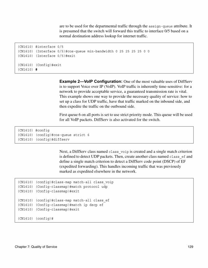
are to be used for the departmental traffic through the assign-queue attribute. It is presumed that the switch will forward this traffic to interface 0/5 based on a normal destination address lookup for internet traffic.
Example 2—VoIP Configuration: One of the most valuable uses of DiffServ is to support Voice over IP (VoIP). VoIP traffic is inherently time-sensitive: for a network to provide acceptable service, a guaranteed transmission rate is vital. This example shows one way to provide the necessary quality of service: how to set up a class for UDP traffic, have that traffic marked on the inbound side, and then expedite the traffic on the outbound side.
First queue 6 on all ports is set to use strict priority mode. This queue will be used for all VoIP packets. DiffServ is also activated for the switch.
Next, a DiffServ class named class_voip is created and a single match criterion is defined to detect UDP packets. Then, create another class named class_ef and define a single match criterion to detect a DiffServ code point (DSCP) of EF (expedited forwarding). This handles incoming traffic that was previously marked as expedited elsewhere in the network.
(CN1610) #interface 0/5(CN1610) (Interface 0/5)#cos-queue min-bandwidth 0 25 25 25 25 0 0(CN1610) (Interface 0/5)#exit
(CN1610) (Config)#exit(CN1610) #
(CN1610) #config(CN1610) (config)#cos-queue strict 6(CN1610) (config)#diffserv
(CN1610) (config)#class-map match-all class_voip(CN1610) (Config-classmap)#match protocol udp(CN1610) (Config-classmap)#exit
(CN1610) (config)#class-map match-all class_ef(CN1610) (Config-classmap)#match ip dscp ef(CN1610) (Config-classmap)#exit
(CN1610) (config)#
Chapter 7: Quality of Service 129
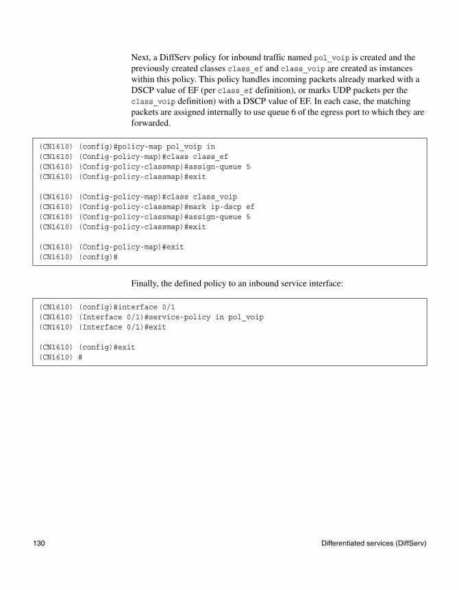
Next, a DiffServ policy for inbound traffic named pol_voip is created and the previously created classes class_ef and class_voip are created as instances within this policy. This policy handles incoming packets already marked with a DSCP value of EF (per class_ef definition), or marks UDP packets per the class_voip definition) with a DSCP value of EF. In each case, the matching packets are assigned internally to use queue 6 of the egress port to which they are forwarded.
Finally, the defined policy to an inbound service interface:
(CN1610) (config)#policy-map pol_voip in(CN1610) (Config-policy-map)#class class_ef(CN1610) (Config-policy-classmap)#assign-queue 5(CN1610) (Config-policy-classmap)#exit
(CN1610) (Config-policy-map)#class class_voip(CN1610) (Config-policy-classmap)#mark ip-dscp ef(CN1610) (Config-policy-classmap)#assign-queue 5(CN1610) (Config-policy-classmap)#exit
(CN1610) (Config-policy-map)#exit(CN1610) (config)#
(CN1610) (config)#interface 0/1(CN1610) (Interface 0/1)#service-policy in pol_voip(CN1610) (Interface 0/1)#exit
(CN1610) (config)#exit(CN1610) #
130 Differentiated services (DiffServ)
Chapter 8: Security Features
8
Security FeaturesAbout this chapter This chapter describes how to configure device security features.
Topics in this chapter
This chapter includes the following topics:
◆ “Denial of service and other protections” on page 132
◆ “Access control lists” on page 134
◆ “IEEE 802.1X” on page 140
◆ “SSH” on page 148
◆ “RADIUS” on page 150
◆ “TACACS+” on page 154
131
Denial of service and other protections
Feature overview Denial of service (DoS) refers to the exploitation of any of a number of vulnerabilities which would interrupt the service of a host or make a network unstable. The CN1610 switch FASTPATH software includes robust protection against DoS attacks.
NoteThe DoS protection feature is always active and does not need or allow any user configuration.
Supported protections
The CN1610 switch supports the following DoS and other protections:
◆ Protection of the switch under packet load: Packet throttling ensures that the switch is manageable under heavy load. Traffic is restructured to a number of packets per second, and packets exceeding the threshold are dropped. Packet throttling is only available on the network interface (that is, the logical management interface); throttling is not offered on the service port or individual front-panel ports.
◆ Protection of the TCP stack: TCP SYN attacks occur when a spoofed TCP connection setup messages are sent to the destination host. This fills up the connection queue and prevents legitimate sessions from being established. As the source IP address in the connection request messages are typically forged, and typically random, this type of attack is difficult to trace.
◆ Protection against open ports: By default, the switch has open ports only for services that are actively enabled and running on the switch. All other ports are closed. Thus, services such as SNTP are not available when the service is configured to be disabled. For the default configuration, there are open ports for such services as Telnet, and SNMP. The switch software provides configuration mechanisms to disable each of these.
◆ Protection against revealing too much information: Information useful to hackers is protected from being revealed to unauthorized sources. The information the switch returns in response to vulnerability analyzer scans is limited in its descriptive nature or is provided by services that can be administratively disabled, such as SNMP.
◆ Disabling forwarding of network-directed broadcasts: The software disables the forwarding of broadcasts that are addressed to a network broadcast address or a subnet broadcast address. Ping requests issued to a network-
132 Denial of service and other protections
directed broadcast address can result in a reply from every host on the subnet or network. The burden of handling the ping replies, can, in turn, cripple the host whose address is identified as the source IP address in the ping request. This is especially problematic if the IP address has been spoofed in the ping request.
◆ Traffic filtering: Access lists can be used to determine which traffic to permit and which to deny. For instance, you can configure an access list to filter any private IP address (as defined by RFC 1918), or to permit only traffic from a recognized subnet.
◆ Rate-limiting traffic: A rate-limiting mechanism is often used to limit traffic. For instance, limitations on ICMP and TCP SYN packets can be implemented as part of the denial of service strategy. On the CN1610 switch, rate limiting can be accomplished using the QoS feature.
Chapter 8: Security Features 133
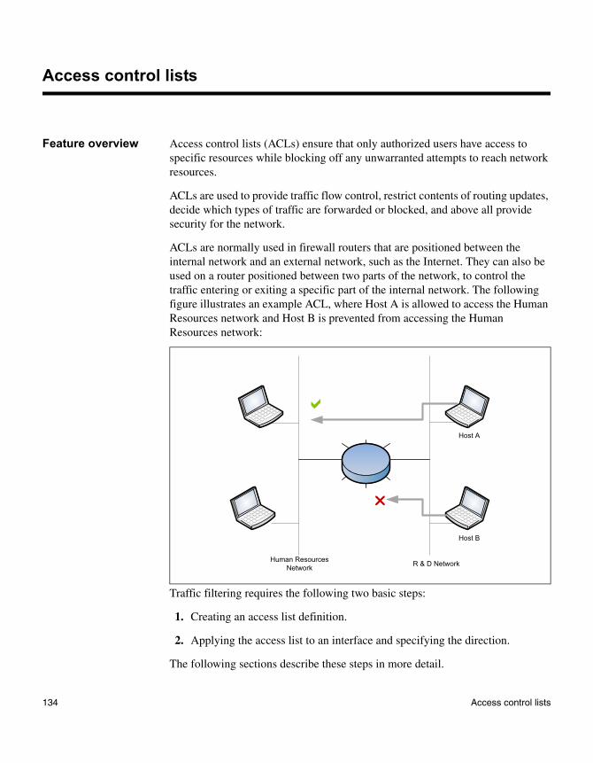
Access control lists
Feature overview Access control lists (ACLs) ensure that only authorized users have access to specific resources while blocking off any unwarranted attempts to reach network resources.
ACLs are used to provide traffic flow control, restrict contents of routing updates, decide which types of traffic are forwarded or blocked, and above all provide security for the network.
ACLs are normally used in firewall routers that are positioned between the internal network and an external network, such as the Internet. They can also be used on a router positioned between two parts of the network, to control the traffic entering or exiting a specific part of the internal network. The following figure illustrates an example ACL, where Host A is allowed to access the Human Resources network and Host B is prevented from accessing the Human Resources network:
Traffic filtering requires the following two basic steps:
1. Creating an access list definition.
2. Applying the access list to an interface and specifying the direction.
The following sections describe these steps in more detail.
�
�
Human ResourcesNetwork R & D Network
Host A
Host B
134 Access control lists
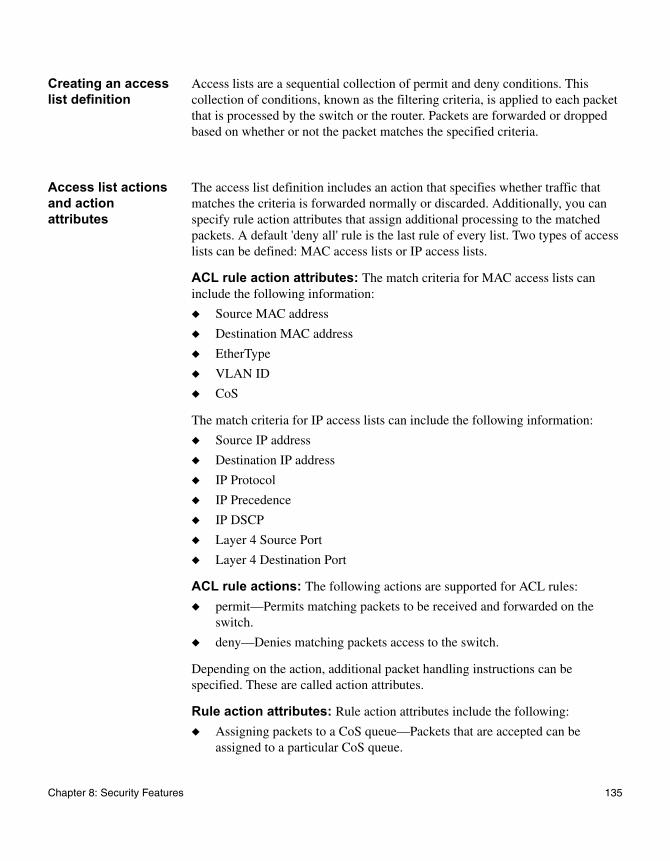
Creating an access list definition
Access lists are a sequential collection of permit and deny conditions. This collection of conditions, known as the filtering criteria, is applied to each packet that is processed by the switch or the router. Packets are forwarded or dropped based on whether or not the packet matches the specified criteria.
Access list actions and action attributes
The access list definition includes an action that specifies whether traffic that matches the criteria is forwarded normally or discarded. Additionally, you can specify rule action attributes that assign additional processing to the matched packets. A default 'deny all' rule is the last rule of every list. Two types of access lists can be defined: MAC access lists or IP access lists.
ACL rule action attributes: The match criteria for MAC access lists can include the following information:
◆ Source MAC address
◆ Destination MAC address
◆ EtherType
◆ VLAN ID
◆ CoS
The match criteria for IP access lists can include the following information:
◆ Source IP address
◆ Destination IP address
◆ IP Protocol
◆ IP Precedence
◆ IP DSCP
◆ Layer 4 Source Port
◆ Layer 4 Destination Port
ACL rule actions: The following actions are supported for ACL rules:
◆ permit—Permits matching packets to be received and forwarded on the switch.
◆ deny—Denies matching packets access to the switch.
Depending on the action, additional packet handling instructions can be specified. These are called action attributes.
Rule action attributes: Rule action attributes include the following:
◆ Assigning packets to a CoS queue—Packets that are accepted can be assigned to a particular CoS queue.
Chapter 8: Security Features 135
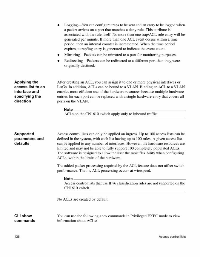
◆ Logging—You can configure traps to be sent and an entry to be logged when a packet arrives on a port that matches a deny rule. This attribute is associated with the rule itself. No more than one trap/ACL rule entry will be generated per minute. If more than one ACL event occurs within a time period, then an internal counter is incremented. When the time period expires, a trap/log entry is generated to indicate the event count.
◆ Mirroring—Packets can be mirrored to a port for monitoring purposes.
◆ Redirecting—Packets can be redirected to a different port than they were originally destined.
Applying the access list to an interface and specifying the direction
After creating an ACL, you can assign it to one or more physical interfaces or LAGs. In addition, ACLs can be bound to a VLAN. Binding an ACL to a VLAN enables more efficient use of the hardware resources because multiple hardware entries for each port can be replaced with a single hardware entry that covers all ports on the VLAN.
NoteACLs on the CN1610 switch apply only to inbound traffic.
Supported parameters and defaults
Access control lists can only be applied on ingress. Up to 100 access lists can be defined in the system, with each list having up to 100 rules. A given access list can be applied to any number of interfaces. However, the hardware resources are limited and may not be able to fully support 100 completely populated ACLs. The software is designed to allow the user the most flexibility when configuring ACLs, within the limits of the hardware.
The added packet processing required by the ACL feature does not affect switch performance. That is, ACL processing occurs at wirespeed.
NoteAccess control lists that use IPv6 classification rules are not supported on the CN1610 switch.
No ACLs are created by default.
CLI show commands
You can use the following show commands in Privileged EXEC mode to view information about ACLs:
136 Access control lists
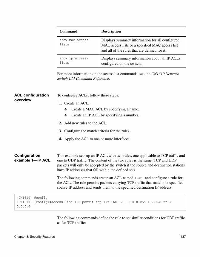
For more information on the access list commands, see the CN1610 Network Switch CLI Command Reference.
ACL configuration overview
To configure ACLs, follow these steps:
1. Create an ACL.
❖ Create a MAC ACL by specifying a name.
❖ Create an IP ACL by specifying a number.
2. Add new rules to the ACL.
3. Configure the match criteria for the rules.
4. Apply the ACL to one or more interfaces.
Configuration example 1—IP ACL
This example sets up an IP ACL with two rules, one applicable to TCP traffic and one to UDP traffic. The content of the two rules is the same. TCP and UDP packets will only be accepted by the switch if the source and destination stations have IP addresses that fall within the defined sets.
The following commands create an ACL named list1 and configure a rule for the ACL. The rule permits packets carrying TCP traffic that match the specified source IP address and sends them to the specified destination IP address.
The following commands define the rule to set similar conditions for UDP traffic as for TCP traffic:
Command Description
show mac access-lists
Displays summary information for all configured MAC access lists or a specified MAC access list and all of the rules that are defined for it.
show ip access-lists
Displays summary information about all IP ACLs configured on the switch.
(CN1610) #config(CN1610) (Config)#access-list 100 permit tcp 192.168.77.0 0.0.0.255 192.168.77.3 0.0.0.0
Chapter 8: Security Features 137
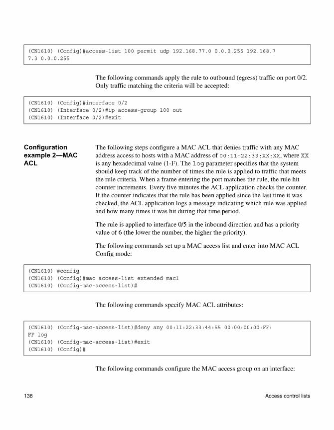
The following commands apply the rule to outbound (egress) traffic on port 0/2. Only traffic matching the criteria will be accepted:
Configuration example 2—MAC ACL
The following steps configure a MAC ACL that denies traffic with any MAC address access to hosts with a MAC address of 00:11:22:33:XX:XX, where XX is any hexadecimal value (1-F). The log parameter specifies that the system should keep track of the number of times the rule is applied to traffic that meets the rule criteria. When a frame entering the port matches the rule, the rule hit counter increments. Every five minutes the ACL application checks the counter. If the counter indicates that the rule has been applied since the last time it was checked, the ACL application logs a message indicating which rule was applied and how many times it was hit during that time period.
The rule is applied to interface 0/5 in the inbound direction and has a priority value of 6 (the lower the number, the higher the priority).
The following commands set up a MAC access list and enter into MAC ACL Config mode:
The following commands specify MAC ACL attributes:
The following commands configure the MAC access group on an interface:
(CN1610) (Config)#access-list 100 permit udp 192.168.77.0 0.0.0.255 192.168.77.3 0.0.0.255
(CN1610) (Config)#interface 0/2(CN1610) (Interface 0/2)#ip access-group 100 out(CN1610) (Interface 0/2)#exit
(CN1610) #config(CN1610) (Config)#mac access-list extended mac1(CN1610) (Config-mac-access-list)#
(CN1610) (Config-mac-access-list)#deny any 00:11:22:33:44:55 00:00:00:00:FF:FF log(CN1610) (Config-mac-access-list)#exit(CN1610) (Config)#
138 Access control lists

(CN1610) (Config)#interface 0/5(CN1610) (config-if-0/5)#mac access-group mac1 in 6
Chapter 8: Security Features 139
IEEE 802.1X
Feature overview LANs are often deployed in environments that allow unauthorized devices to be physically attached to the LAN infrastructure, or allow unauthorized users to attempt to access the LAN through equipment already attached. In such environments, it may be desirable to restrict access to the services offered by the LAN.
Port-based network access control makes use of the physical characteristics of LAN infrastructures to provide a means of authenticating and authorizing devices attached to a LAN port. Port-based network access control prevents access to the port in cases in which the authentication and authorization process fails. A port is defined as a single point of attachment to the LAN.
The software also supports VLAN assignment clients based on the RADIUS server authentication. The CN1610 switch supports an 802.1X Authenticator service with a local authentication server or authentication that uses remote RADIUS or TACACS+ servers.
Supported security methods for communication with remote servers include MD5, PEAP, EAP-TTL, EAP-TTLS, and EAP-TLS.
Local 802.1X authentication server
The CN1610 switch supports a dedicated database for local authentication of users for network access through the 802.1X feature. This functionality is distinct from management access for the switch. This feature supports creating users for 802.1X (port) access only.
Multiuser VLAN assignment
The multiuser VLAN assignment feature allows RADIUS-specified attributes, such as the VLAN ID and Filter ID, to be associated with an authenticated client. When a client authenticates successfully, if a VLAN attribute is sent by the RADIUS server, the client is associated with the RADIUS-assigned VLAN; that is, traffic from and to that client flows through the RADIUS-assigned VLAN. Similarly, when the client authenticates successfully, if a Filter ID attribute is specified by the RADIUS server, this Filter ID is applied to the traffic from that client. The Filter ID identifies a DiffServ policy on the switch.
140 IEEE 802.1X
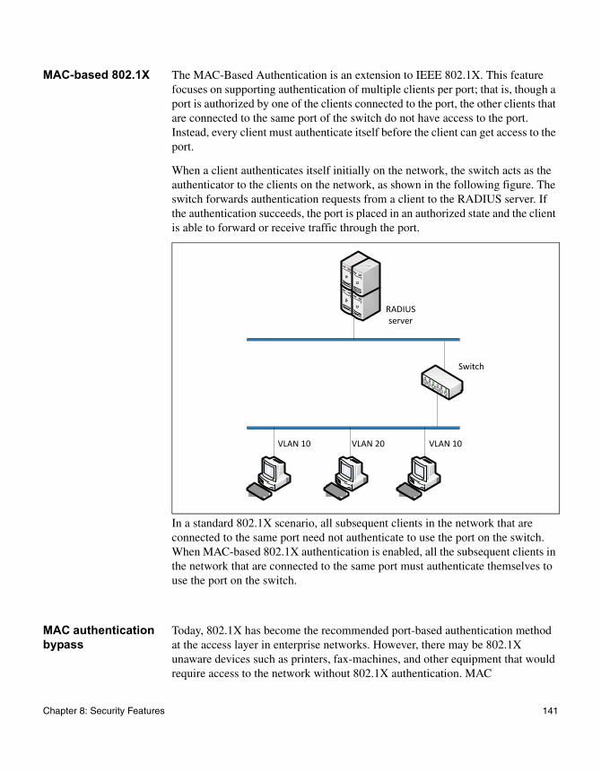
MAC-based 802.1X The MAC-Based Authentication is an extension to IEEE 802.1X. This feature focuses on supporting authentication of multiple clients per port; that is, though a port is authorized by one of the clients connected to the port, the other clients that are connected to the same port of the switch do not have access to the port. Instead, every client must authenticate itself before the client can get access to the port.
When a client authenticates itself initially on the network, the switch acts as the authenticator to the clients on the network, as shown in the following figure. The switch forwards authentication requests from a client to the RADIUS server. If the authentication succeeds, the port is placed in an authorized state and the client is able to forward or receive traffic through the port.
In a standard 802.1X scenario, all subsequent clients in the network that are connected to the same port need not authenticate to use the port on the switch. When MAC-based 802.1X authentication is enabled, all the subsequent clients in the network that are connected to the same port must authenticate themselves to use the port on the switch.
MAC authentication bypass
Today, 802.1X has become the recommended port-based authentication method at the access layer in enterprise networks. However, there may be 802.1X unaware devices such as printers, fax-machines, and other equipment that would require access to the network without 802.1X authentication. MAC
VLAN 10 VLAN 20 VLAN 10
Switch
RADIUS server
Chapter 8: Security Features 141
Authentication Bypass (MAB) is a supplemental authentication mechanism to allow 802.1X unaware clients to authenticate to the network. It uses the 802.1X infrastructure and MAB cannot be supported independent of the 802.1X component.
MAC Authentication Bypass (MAB) provides 802.1X-unaware clients controlled access to the network by using the devices' MAC address as an identifier. This requires that the known and allowable MAC address and corresponding access rights be prepopulated in the authentication server. MAB only works when the port control mode of the port is MAC-based.
MAB can be configured per port. This also makes it possible for the 802.1X-unaware client to be placed in a RADIUS assigned VLAN or apply a specific Filter ID to the client traffic.
Guest VLAN The guest VLAN feature enables the switch to provide a distinguished service to unauthenticated users (not rogue users who fail authentication). This feature provides a mechanism to allow visitors and contractors to have network access to reach an external network with no ability to surf an internal LAN.
When a client that does not support 802.1X is connected to an unauthorized port that is 802.1X-enabled, the client does not respond to the 802.1X requests from the switch. Therefore, the port remains in the unauthorized state, and the client is not granted access to the network. If a guest VLAN is configured for that port, then the port is placed in the configured guest VLAN, and the port is moved to the authorized state, allowing access to the client.
Client devices that are 802.1X supplicant-enabled authenticate with the switch when they are plugged into the 802.1X-enabled switch port. The switch verifies the credentials of the client by communicating with an authentication server. If the credentials are verified, the authentication server informs the switch to 'unblock' the switch port and allows the client unrestricted access to the network; that is, the client is a member of an internal VLAN.
Guest VLAN supplicant mode is a global configuration for all the ports on the switch. When a port is configured for guest VLAN in this mode, if a client fails authentication on the port, the client is assigned to the guest VLAN configured on that port. The port is assigned a guest VLAN ID and is moved to the authorized status. Disabling the supplicant mode does not clear the ports that are already authorized or the assigned guest VLAN IDs.
142 IEEE 802.1X
802.1X monitor mode
Monitor mode is a special mode that can be enabled in conjunction with 802.1X authentication. It allows network access even in cases where there is a failure to authenticate but logs the results of the authentication process for diagnostic purposes. The exact details are described in the following sections. The main aim of monitor mode is to provide a mechanism to the operator to be able to identify the short-comings in the configuration of a 802.1X authentication on the switch without affecting the network access to the users of the switch.
RADIUS-based dynamic VLAN assignment
If VLAN assignment is enabled in the RADIUS server, then as part of the response message, the RADIUS server sends the VLAN ID which the client is requested to use in the 802.1X tunnel attributes. If dynamic VLAN creation is enabled on the switch and the RADIUS assigned VLAN does not exist, then the assigned VLAN is dynamically created. This implies that the client can connect from any port and be assigned to the appropriate VLAN. This gives flexibility for clients to move around the network without requiring the operator to perform additional provisioning for each network interface.
Features not supported
◆ As stated in section C.2.2 in IEEE 802.1X-2001, an Authenticator-enabled switch could reset port counters after authentication succeeds to allow the switch to maintain session statistics. The CN1610 switch does not support this action; therefore, the Authenticator Session Statistics that are defined in IEEE-802.1X-2001 are not supported.
◆ The configuration option suggested in IEEE 802.1X-2001 section C.3.1 that enables piggybacking prevention/detection is not supported.
◆ Size restrictions:
❖ User Name: 64 bytes
❖ RADIUS Server State attribute: 253 bytes
❖ RADIUS Server Class attribute: 253 bytes
Defaults The 801.X MAC-based authentication, guest VLAN, RADIUS authentication, and RADIUS-assigned VLAN features are disabled by default.
For additional default values, see the CN1610 Network Switch CLI Command Reference.
Chapter 8: Security Features 143
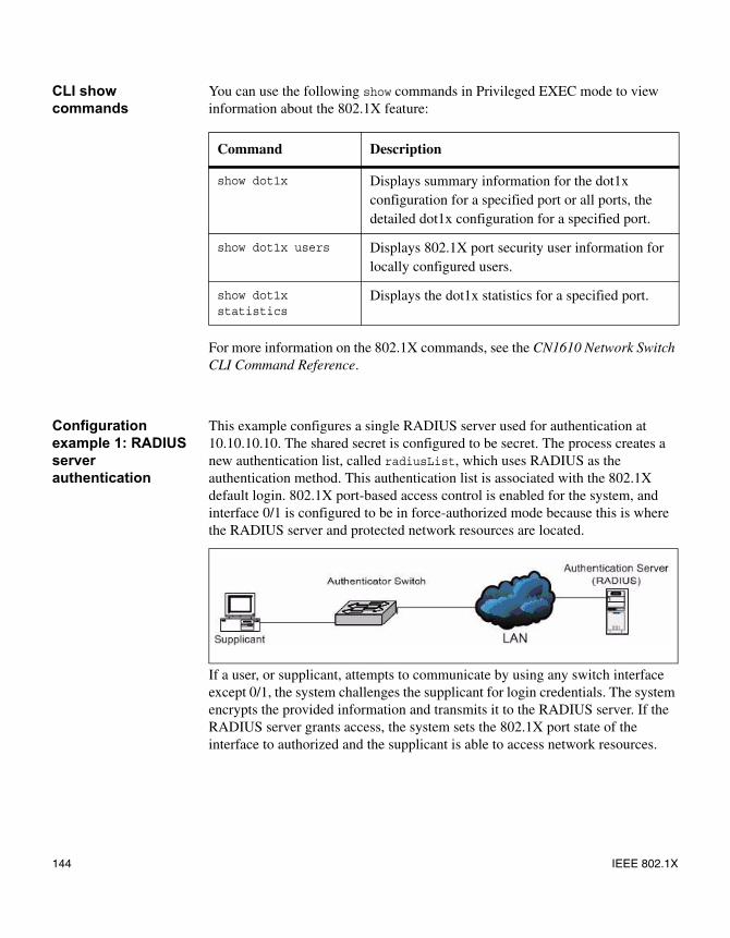
CLI show commands
You can use the following show commands in Privileged EXEC mode to view information about the 802.1X feature:
For more information on the 802.1X commands, see the CN1610 Network Switch CLI Command Reference.
Configuration example 1: RADIUS server authentication
This example configures a single RADIUS server used for authentication at 10.10.10.10. The shared secret is configured to be secret. The process creates a new authentication list, called radiusList, which uses RADIUS as the authentication method. This authentication list is associated with the 802.1X default login. 802.1X port-based access control is enabled for the system, and interface 0/1 is configured to be in force-authorized mode because this is where the RADIUS server and protected network resources are located.
If a user, or supplicant, attempts to communicate by using any switch interface except 0/1, the system challenges the supplicant for login credentials. The system encrypts the provided information and transmits it to the RADIUS server. If the RADIUS server grants access, the system sets the 802.1X port state of the interface to authorized and the supplicant is able to access network resources.
Command Description
show dot1x Displays summary information for the dot1x configuration for a specified port or all ports, the detailed dot1x configuration for a specified port.
show dot1x users Displays 802.1X port security user information for locally configured users.
show dot1x statistics
Displays the dot1x statistics for a specified port.
144 IEEE 802.1X
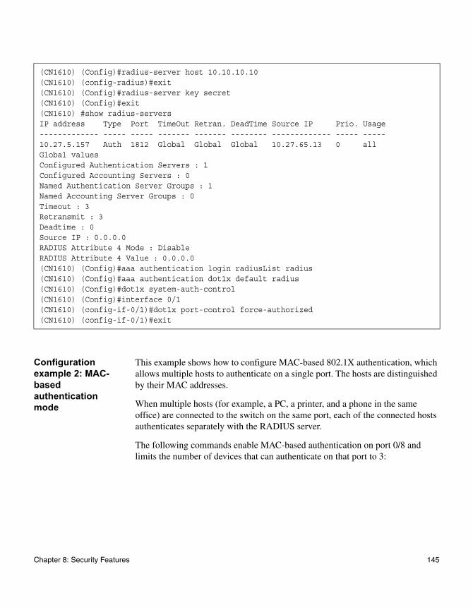
Configuration example 2: MAC-based authentication mode
This example shows how to configure MAC-based 802.1X authentication, which allows multiple hosts to authenticate on a single port. The hosts are distinguished by their MAC addresses.
When multiple hosts (for example, a PC, a printer, and a phone in the same office) are connected to the switch on the same port, each of the connected hosts authenticates separately with the RADIUS server.
The following commands enable MAC-based authentication on port 0/8 and limits the number of devices that can authenticate on that port to 3:
(CN1610) (Config)#radius-server host 10.10.10.10(CN1610) (config-radius)#exit(CN1610) (Config)#radius-server key secret(CN1610) (Config)#exit(CN1610) #show radius-serversIP address Type Port TimeOut Retran. DeadTime Source IP Prio. Usage------------- ----- ----- ------- ------- -------- ------------- ----- -----10.27.5.157 Auth 1812 Global Global Global 10.27.65.13 0 allGlobal valuesConfigured Authentication Servers : 1Configured Accounting Servers : 0Named Authentication Server Groups : 1Named Accounting Server Groups : 0Timeout : 3Retransmit : 3Deadtime : 0Source IP : 0.0.0.0RADIUS Attribute 4 Mode : DisableRADIUS Attribute 4 Value : 0.0.0.0(CN1610) (Config)#aaa authentication login radiusList radius(CN1610) (Config)#aaa authentication dot1x default radius(CN1610) (Config)#dot1x system-auth-control(CN1610) (Config)#interface 0/1(CN1610) (config-if-0/1)#dot1x port-control force-authorized(CN1610) (config-if-0/1)#exit
Chapter 8: Security Features 145
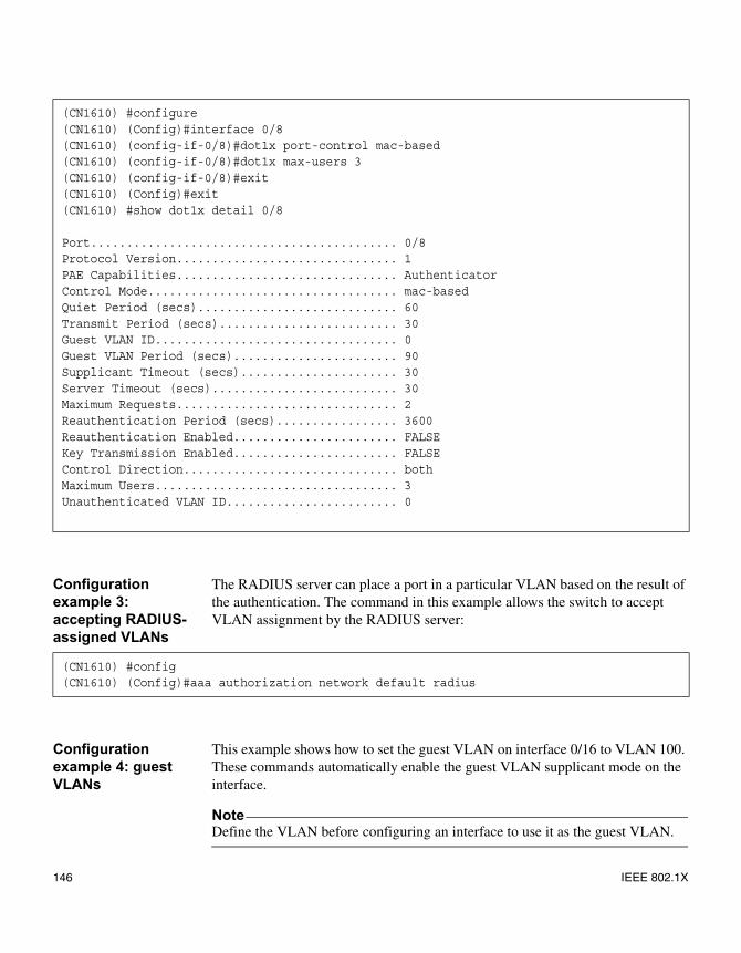
Configuration example 3: accepting RADIUS-assigned VLANs
The RADIUS server can place a port in a particular VLAN based on the result of the authentication. The command in this example allows the switch to accept VLAN assignment by the RADIUS server:
Configuration example 4: guest VLANs
This example shows how to set the guest VLAN on interface 0/16 to VLAN 100. These commands automatically enable the guest VLAN supplicant mode on the interface.
NoteDefine the VLAN before configuring an interface to use it as the guest VLAN.
(CN1610) #configure(CN1610) (Config)#interface 0/8(CN1610) (config-if-0/8)#dot1x port-control mac-based(CN1610) (config-if-0/8)#dot1x max-users 3(CN1610) (config-if-0/8)#exit(CN1610) (Config)#exit(CN1610) #show dot1x detail 0/8
Port........................................... 0/8Protocol Version............................... 1PAE Capabilities............................... AuthenticatorControl Mode................................... mac-basedQuiet Period (secs)............................ 60Transmit Period (secs)......................... 30Guest VLAN ID.................................. 0Guest VLAN Period (secs)....................... 90Supplicant Timeout (secs)...................... 30Server Timeout (secs).......................... 30Maximum Requests............................... 2Reauthentication Period (secs)................. 3600Reauthentication Enabled....................... FALSEKey Transmission Enabled....................... FALSEControl Direction.............................. bothMaximum Users.................................. 3Unauthenticated VLAN ID........................ 0
(CN1610) #config(CN1610) (Config)#aaa authorization network default radius
146 IEEE 802.1X
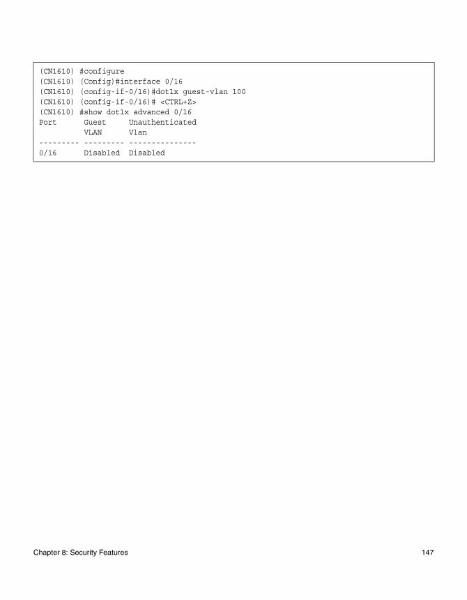
(CN1610) #configure(CN1610) (Config)#interface 0/16(CN1610) (config-if-0/16)#dot1x guest-vlan 100(CN1610) (config-if-0/16)# <CTRL+Z>(CN1610) #show dot1x advanced 0/16Port Guest Unauthenticated
VLAN Vlan--------- --------- ---------------0/16 Disabled Disabled
Chapter 8: Security Features 147
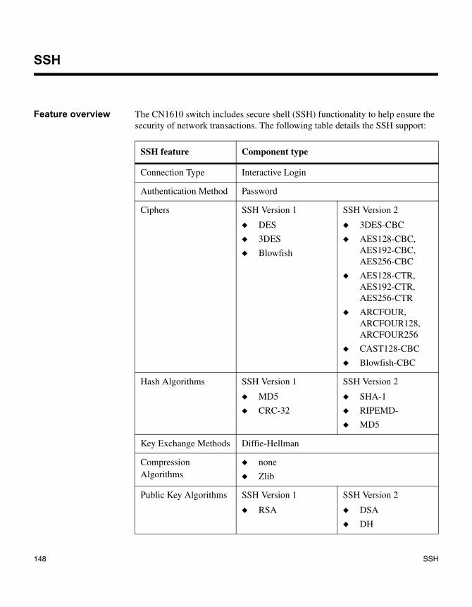
SSH
Feature overview The CN1610 switch includes secure shell (SSH) functionality to help ensure the security of network transactions. The following table details the SSH support:
SSH feature Component type
Connection Type Interactive Login
Authentication Method Password
Ciphers SSH Version 1
◆ DES
◆ 3DES
◆ Blowfish
SSH Version 2
◆ 3DES-CBC
◆ AES128-CBC, AES192-CBC, AES256-CBC
◆ AES128-CTR, AES192-CTR, AES256-CTR
◆ ARCFOUR, ARCFOUR128, ARCFOUR256
◆ CAST128-CBC
◆ Blowfish-CBC
Hash Algorithms SSH Version 1
◆ MD5
◆ CRC-32
SSH Version 2
◆ SHA-1
◆ RIPEMD-
◆ MD5
Key Exchange Methods Diffie-Hellman
Compression Algorithms
◆ none
◆ Zlib
Public Key Algorithms SSH Version 1
◆ RSA
SSH Version 2
◆ DSA
◆ DH
148 SSH
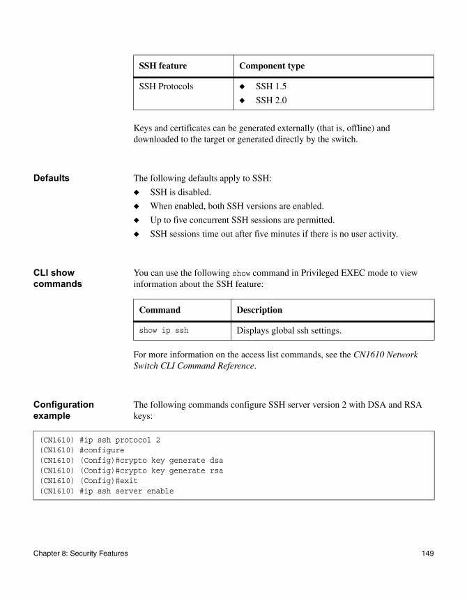
Keys and certificates can be generated externally (that is, offline) and downloaded to the target or generated directly by the switch.
Defaults The following defaults apply to SSH:
◆ SSH is disabled.
◆ When enabled, both SSH versions are enabled.
◆ Up to five concurrent SSH sessions are permitted.
◆ SSH sessions time out after five minutes if there is no user activity.
CLI show commands
You can use the following show command in Privileged EXEC mode to view information about the SSH feature:
For more information on the access list commands, see the CN1610 Network Switch CLI Command Reference.
Configuration example
The following commands configure SSH server version 2 with DSA and RSA keys:
SSH Protocols ◆ SSH 1.5
◆ SSH 2.0
SSH feature Component type
Command Description
show ip ssh Displays global ssh settings.
(CN1610) #ip ssh protocol 2(CN1610) #configure(CN1610) (Config)#crypto key generate dsa(CN1610) (Config)#crypto key generate rsa(CN1610) (Config)#exit(CN1610) #ip ssh server enable
Chapter 8: Security Features 149
RADIUS
Feature overview Managing and determining the validity of users in a large network can be significantly simplified by making use of a single database of accessible information as in an authentication server. These servers are most commonly found to be supporting the Remote Authentication Dial In User Service (RADIUS) protocol as defined by RFC 2865.
RADIUS allows access to a user's authentication and configuration information contained on the server only when requests are received from a client that shares an encrypted secret with the server. This “secret” is never transmitted over the network in an attempt to maintain a secure environment. Any requests from clients that are not appropriately configured with the secret or access from unauthorized devices are silently discarded by the server.
NoteSilently discarded packets are abandoned without any further processing; however, the CN1610 switch RADIUS client generates logs and increments status counters to record these occurrences.
RADIUS conforms to a client/server model with secure communications that use UDP as a transport protocol. It is extremely flexible, supporting a variety of methods to authenticate and statistically track users. It is very extensible allowing for new methods of authentication to be added without disrupting existing functionality. This section describes the implementation of portions of a RADIUS client and extensions as supported by the CN1610 switch.
RADIUS server functionality is not supported. The client communicates exclusively with external RADIUS servers accessible through a network interface.
Authentication operation
The RADIUS standard has become the protocol of choice by administrators of large accessible networks when authenticating users prior to access. To accomplish the authentication in a secure manner, a RADIUS client and a RADIUS server must both be configured with the same shared password or “secret.” This secret is used to generate one-way encrypted authenticators that are present in all RADIUS packets. These authenticators sufficiently reduce the possibility of a malicious user correctly spoofing packets without knowledge of the exact secret.
150 RADIUS
As a user attempts to connect to a functioning RADIUS supported network, contact is first detected by a device referred to as the Network Access Server (NAS). The NAS prompts the user for a name and password. The supplied information is then encrypted and a request is transported by a RADIUS client to a preconfigured RADIUS server. The server may authenticate the user itself, or make use of a back-end device to ascertain authenticity. In either case, a response may or may not be forthcoming to the client. If the server accepts the user, a positive result is returned with attributes containing configuration information. If the server rejects the user, a negative result is returned. If the server rejects the client or the shared secrets differ, no result is returned.
If the server requires additional verification from the user, a challenge is returned and the request process is started again. This challenge mechanism works if the application using RADIUS is 802.1X; it will not work, however, if the application using RADIUS is the User Manager. There is no state information maintained as requests are preserved and then correlated to responses before verifying their authenticity. If an authentication request times out, after a configurable timeout period elapses, the client can retransmit packets and use alternate servers. All sensitive information is encrypted by using the MD5 algorithm, and the shared secret is never sent over the network.
Limitations The following limitations apply to RADIUS client support:
◆ RFC 2865 has effectively limited the number of outstanding requests that can be simply correlated with any received responses to 256.
◆ Although the underlying RADIUS code supports challenge messages, the switch user interface does not integrate support for RADIUS challenge messages.
◆ The RADIUS implementation on the CN1610 switch does not support IPv6.
Defaults RADIUS authentication and accounting is disabled and no servers are configured by default.
For additional default values, see the CN1610 Network Switch CLI Command Reference.
CLI show commands
You can use the following show commands in Privileged EXEC mode to view information about the RADIUS feature:
Chapter 8: Security Features 151
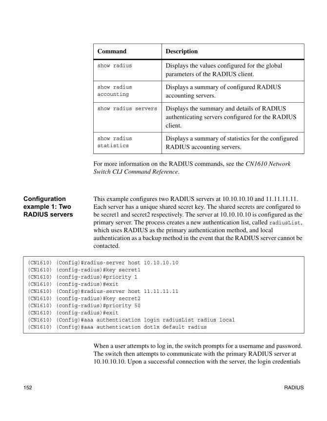
For more information on the RADIUS commands, see the CN1610 Network Switch CLI Command Reference.
Configuration example 1: Two RADIUS servers
This example configures two RADIUS servers at 10.10.10.10 and 11.11.11.11. Each server has a unique shared secret key. The shared secrets are configured to be secret1 and secret2 respectively. The server at 10.10.10.10 is configured as the primary server. The process creates a new authentication list, called radiusList, which uses RADIUS as the primary authentication method, and local authentication as a backup method in the event that the RADIUS server cannot be contacted.
When a user attempts to log in, the switch prompts for a username and password. The switch then attempts to communicate with the primary RADIUS server at 10.10.10.10. Upon a successful connection with the server, the login credentials
Command Description
show radius Displays the values configured for the global parameters of the RADIUS client.
show radius accounting
Displays a summary of configured RADIUS accounting servers.
show radius servers Displays the summary and details of RADIUS authenticating servers configured for the RADIUS client.
show radius statistics
Displays a summary of statistics for the configured RADIUS accounting servers.
(CN1610) (Config)#radius-server host 10.10.10.10(CN1610) (config-radius)#key secret1(CN1610) (config-radius)#priority 1(CN1610) (config-radius)#exit(CN1610) (Config)#radius-server host 11.11.11.11(CN1610) (config-radius)#key secret2(CN1610) (config-radius)#priority 50(CN1610) (config-radius)#exit(CN1610) (Config)#aaa authentication login radiusList radius local(CN1610) (Config)#aaa authentication dot1x default radius
152 RADIUS

will be exchanged over an encrypted channel. The server grants or denies access, which the switch honors, and either allows or does not allow the user to access the switch.
If neither of the two servers can be contacted, the switch searches its local user database for the user.
Configuration example 2: setting the NAS IP address
The NAS-IP-Address attribute identifies the IP address of the network authentication server (NAS) that is requesting authentication of the user. The address should be unique to the NAS within the scope of the RADIUS server.
The NAS IP address is only used in RADIUS Access-Request packets. Either the NAS-IP-Address field or the NASIdentifier field must be present in an Access-Request packet.
The following command sets the NAS-IP address. If you do not specify an IP address in the command, the NAS-IP address uses the interface IP address that connects the switch to the RADIUS server.
(CN1610) #config(CN1610) (Config)#radius-server attribute 4 192.168.20.12
Chapter 8: Security Features 153
TACACS+
Feature overview TACACS+ provides access control for networked devices by using one or more centralized servers, similar to RADIUS. This protocol simplifies authentication by making use of a single database that can be shared by many clients on a large network. TACACS+ is based on the TACACS protocol (described in RFC1492) but also provides for separate authentication, authorization, and accounting services. The original protocol was UDP-based, with messages passed in clear text over the network; TACACS+ uses TCP to ensure reliable delivery, and uses a shared key configured on the client and daemon server to encrypt all messages.
When TACACS+ is configured as the authentication method for a user login type (CLI), NAS prompts for the user login credentials and requests services from the TACACS+ client; the client then uses the configured list of servers for authentication and provides results back to the NAS.
The TACACS+ server list is configured with one or more hosts defined by their network IP address or host name; each can be assigned a priority to determine the order in which the TACACS+ client will contact them, and a server is contacted when a connection attempt fails or times out for a higher priority server. Each server host can be separately configured with a specific connection type, port, timeout, shared key, and source IP value, or the global configuration can be used. Like RADIUS, the TACACS+ server may do the authentication itself, or redirect the request to another back-end device. All sensitive information is encrypted based on a shared secret key and a series of MD5 hashes, as specified in the protocol. The shared secret is never passed over the network.
The TACACS+ client supports the login and change password authentication messages with the ASCII authentication type.
NoteThe TACACS+ client does not support IPv6.
Supported parameters and defaults
The following TACACS+ parameters can be configured or viewed using the CLI:
154 TACACS+
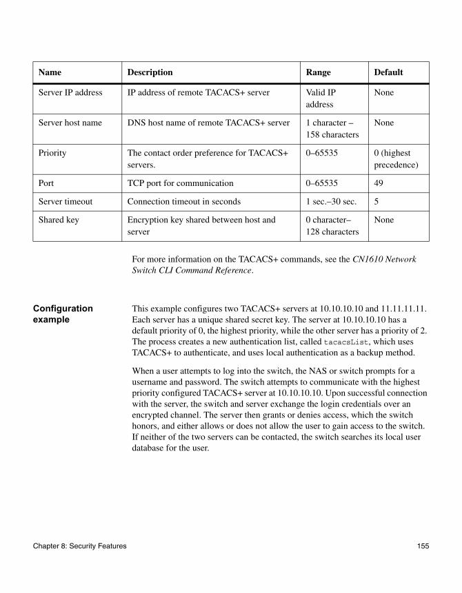
For more information on the TACACS+ commands, see the CN1610 Network Switch CLI Command Reference.
Configuration example
This example configures two TACACS+ servers at 10.10.10.10 and 11.11.11.11. Each server has a unique shared secret key. The server at 10.10.10.10 has a default priority of 0, the highest priority, while the other server has a priority of 2. The process creates a new authentication list, called tacacsList, which uses TACACS+ to authenticate, and uses local authentication as a backup method.
When a user attempts to log into the switch, the NAS or switch prompts for a username and password. The switch attempts to communicate with the highest priority configured TACACS+ server at 10.10.10.10. Upon successful connection with the server, the switch and server exchange the login credentials over an encrypted channel. The server then grants or denies access, which the switch honors, and either allows or does not allow the user to gain access to the switch. If neither of the two servers can be contacted, the switch searches its local user database for the user.
Name Description Range Default
Server IP address IP address of remote TACACS+ server Valid IP address
None
Server host name DNS host name of remote TACACS+ server 1 character –158 characters
None
Priority The contact order preference for TACACS+ servers.
0–65535 0 (highest precedence)
Port TCP port for communication 0–65535 49
Server timeout Connection timeout in seconds 1 sec.–30 sec. 5
Shared key Encryption key shared between host and server
0 character–128 characters
None
Chapter 8: Security Features 155
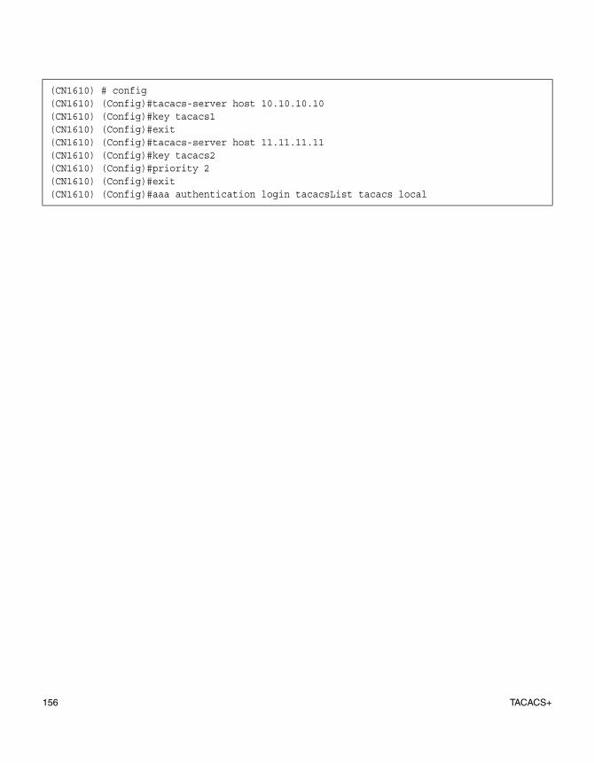
(CN1610) # config(CN1610) (Config)#tacacs-server host 10.10.10.10(CN1610) (Config)#key tacacs1(CN1610) (Config)#exit(CN1610) (Config)#tacacs-server host 11.11.11.11(CN1610) (Config)#key tacacs2(CN1610) (Config)#priority 2(CN1610) (Config)#exit(CN1610) (Config)#aaa authentication login tacacsList tacacs local
156 TACACS+
Glossary
AAA Authentication, Authorization, and Accounting
ACL Access Control List
ARP Address Resolution Protocol
CIST Common and Internal Spanning Tree
CLI Command-Line Interface
DHCP Dynamic Host Configuration Protocol
DSCP Differentiated Services Code Point
EAP Extensible Authentication Protocol
EAPOL EAP over LAN
GARP Generic Attribution Registration Protocol
GVRP GARP VLAN Registration Protocol
IGMP Internet Group Management Protocol
Glossary 157
IVL Independent VLAN
LACP Link Aggregation Control Protocol
MAC Media Access Control
MDIX Management Dependent Interface Crossover
Mirror port Source Mirror Port (the port that mirrors to probe)
Mirroring port Destination Mirror Port
Monitor port Destination Mirror Port (the port with probe attached)
MSTP Multiple Spanning Tree Protocol
NIM Network Interface Manager
PAE Port Access Entity
Probe port Destination Mirror Port (the port with probe attached)
QoS Quality of Service
RADIUS Remote Authentication Dial In User Service
158
RSTP Rapid Spanning Tree Protocol
SNTP Simple Network Time Protocol
SSH Secure Shell
STP Spanning Tree Protocol
TACACS Terminal Access Controller Access Control System
VLAN Virtual LAN
Glossary 159

160
Index
Numerics802.1X 140802.1x
MAC-based 141monitor mode 143
802.1X authentication server, local 140
Aaccess control lists 134access ports 109, 110ACLs
binding to a VLAN 136rules 135
additional documentation 1authentication 25
Bbinding an ACL to a VLAN 136BOOTP/DHCP client 6BPDUs 81
CCIST 81CLI
connecting to 4quick start 4scripting 15
command line logging 10command modes 4commands
entering 5saving to a script 14using scripts to enter 13using the “no” form of 5
common and internal spanning tree 81configuration files
overview 20configuration files, supported 12control packet behavior 86
CoS mapping behaviors 117CoS queue
configuration 119mapping 116
Ddenial of service 132DHCP/BOOTP client 6DNS client 36double VLAN tag 109downloading files 20dynamic LAGs 48dynamic VLAN assignment, RADIUS-based 143
Eenhanced LAG hashing 49entering commands 5environmental status 39
Ffile uploads, example 15files
configuring 20copying 15managing 11uploads and downloads 20
flow control 76flow-based mirroring 72forwarding database
Layer 2 54
Gguest VLAN 142
Hhelp, entering commands 5
Index 161

IIGMP snooping 66Industry Standard Discovery Protocol 62in-memory log 27interface notation, LAGs 48interfaces, switch management 6IP-subnet-based VLANs 106IPv6 management 8
Jjumbo frames 69
LLAG hashing 48LAGs
interface numbers 48static and dynamic 48
Layer 2 forwarding database 54link aggregation 48link failures and additions 50Link Layer Discovery Protocol 58LLDP
parameters 59receive 59transmit 59
log messagesexample 29
loggingseverity 10
logging, command line 10logs
access 28criteria 27format and attributes 28in-memory 27local persistent 27types 27versions 28
MMAC authentication bypass 141MAC-based 802.1X 141
MAC-based VLANs 104management
interfaces 6IPv6 8users 24
management interfaces 6mapping, CoS queue 116MIBs, supported 22mirroring
flow-based 72port 70
MSTPactive topology enforcement 85states 82
multiple spanning tree regiions 82multiuser VLAN assignment 140
Nno form of a command 5
Ppersistent log, local 27ports
access and uplink 109configuration 44mirroring 70service provider, uplink 110trusted 116untrusted 116
protocol-based VLANs 100
QQoS
configuration example 120overview 116
queue configuration, CoS 119queue mapping, CoS 116
RRADIUS,
overview 150RADIUS-based dynamic VLAN assignment 143
162 Index
rules, ACL 135
SSCP 19scripting, CLI 15scripts, using to enter commands 13service provider port, uplink 110SFP modules, supported 47SFTP 19SNMP
overview 22session limits, Telnet and 19
SNMP server configuration 22SNTP 32spanning tree
CIST 81VID assignment to 83
SSH 148static LAGs 48storm control
overview 74parameters 75
switch management interfaces 6syslog
configuration 30overview 27
TTACACS+ 154tagging, double VLAN 109Telnet
outbound 41session limits 19
TFTP 18
TLVs, supported by LLDP 58traps
conditions that generate 39trusted ports 116
Uuntrusted ports 116uplink ports 109uploading files
example 15overview 20
user management 24
VVID to spanning tree assignment 83VLAN assignment
multiuser 140RADIUS-based 143
VLAN tagging, double 109VLAN, binding an ACL to a 136VLAN, default 99VLAN, guest 142VLANs
assigning ports to 99creating 99IP-subnet-based 106MAC-based 104overview 96protocol-based 100
XXMODEM 19
163 Index

164 Index