Embed Size (px)
Citation preview
Presentation_ID 1
Training Course on Network Administration
03 March 2013-07 March 2014
National Centre for Physics
© 2008 Cisco Systems, Inc. All rights reserved. Cisco ConfidentialPresentation_ID 2
Network LayerNetwork Layer
Network Basics
Presentation_ID 3
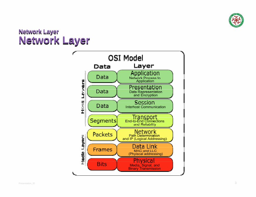
Network Layer
Network LayerNetwork Layer
Network Layer
Presentation_ID 4
Network Layer Protocols
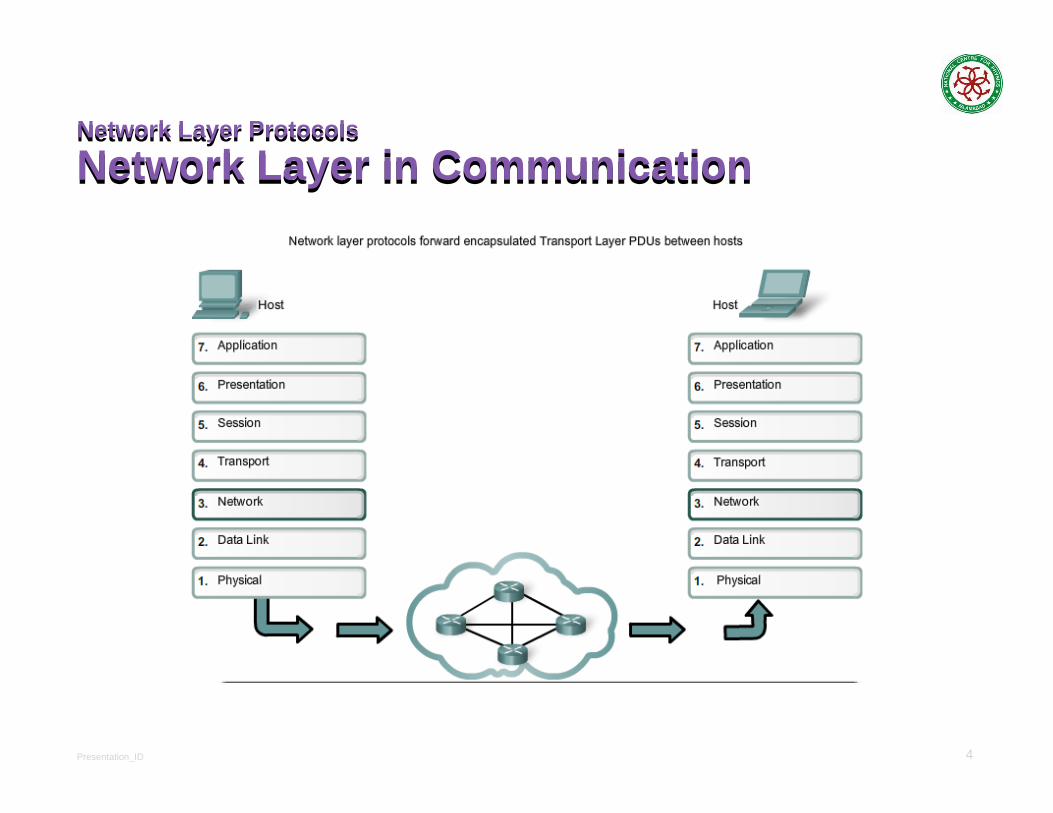
Network Layer in CommunicationNetwork Layer Protocols
Network Layer in Communication
Presentation_ID 5
Network Layer in Communication
The Network LayerNetwork Layer in Communication
The Network LayerEnd to End Transport processes
Addressing end devices
Encapsulation
Routing
De-encapsulating
Common Network Layer Protocols
Internet Protocol version 4 (IPv4)
Internet Protocol version 6 (IPv6
Presentation_ID 6
Characteristics of the IP protocol
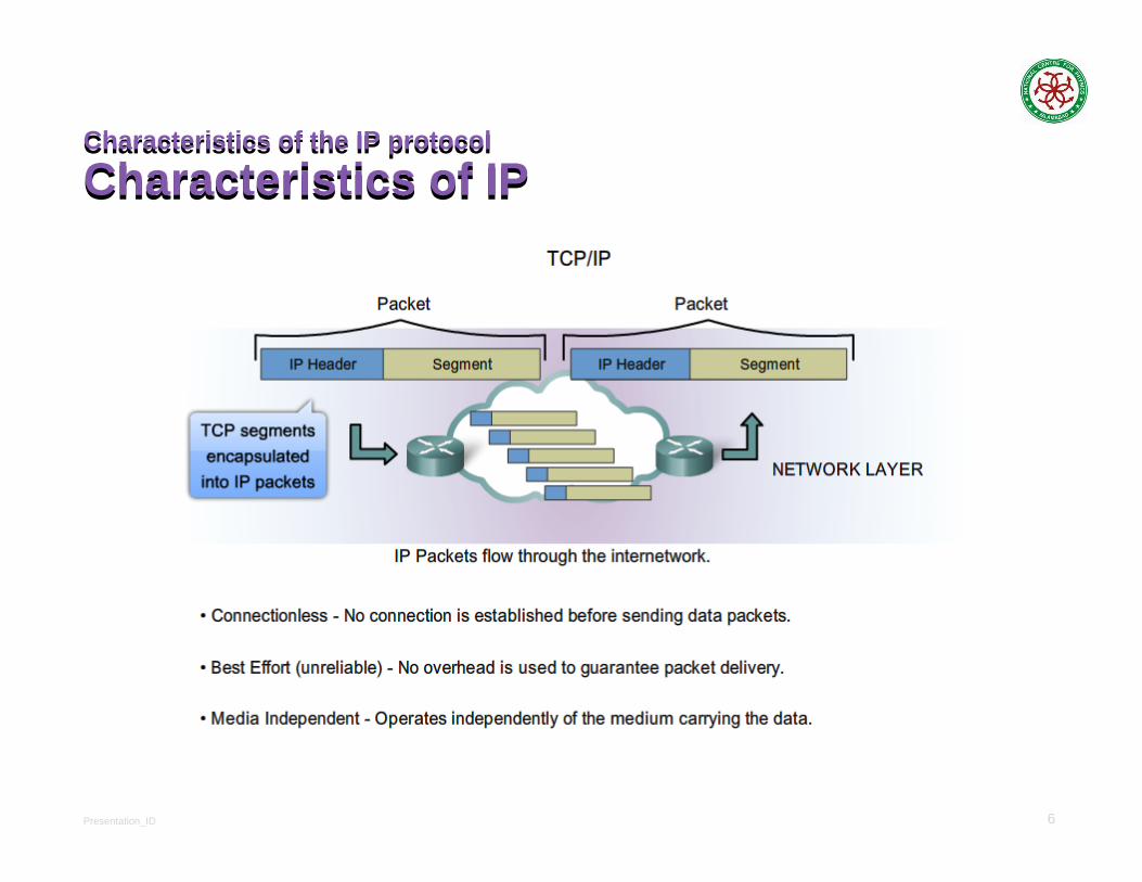
Characteristics of IPCharacteristics of the IP protocol
Characteristics of IP
Presentation_ID 7
Characteristics of the IP protocol
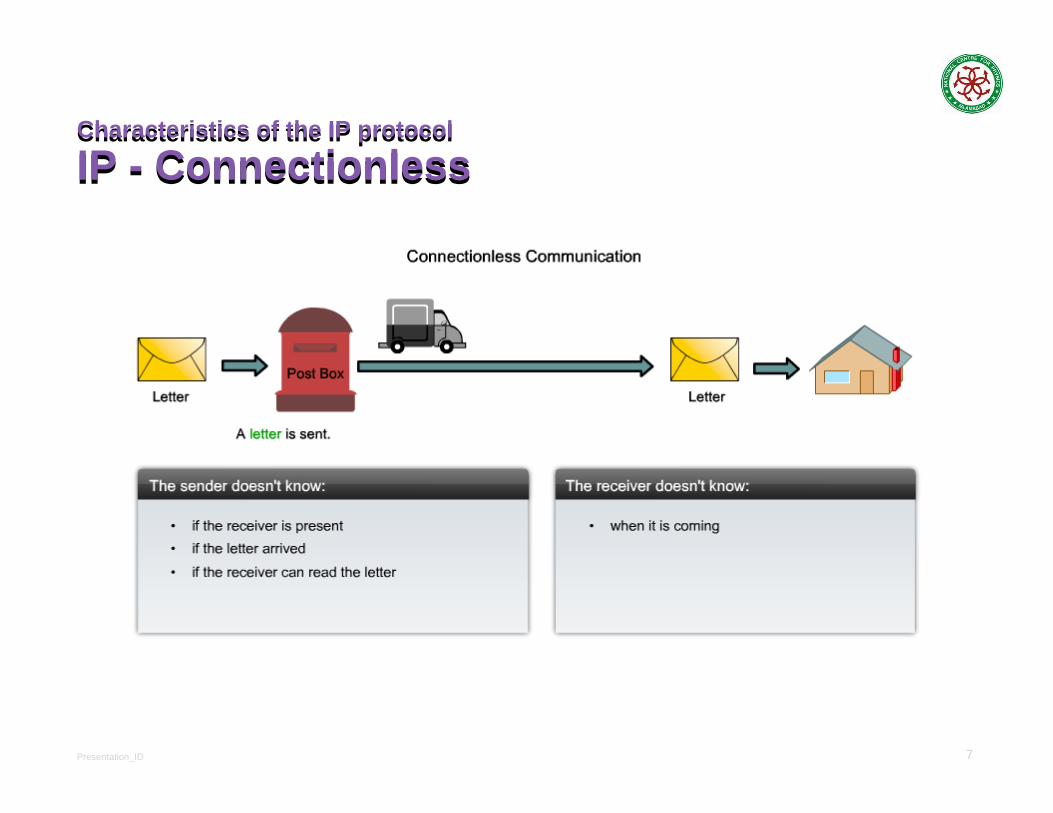
IP - ConnectionlessCharacteristics of the IP protocol
IP - Connectionless

Presentation_ID 8
Characteristics of the IP protocol
IP – Best Effort DeliveryCharacteristics of the IP protocol
IP – Best Effort Delivery
Presentation_ID 9
Characteristics of the IP protocol
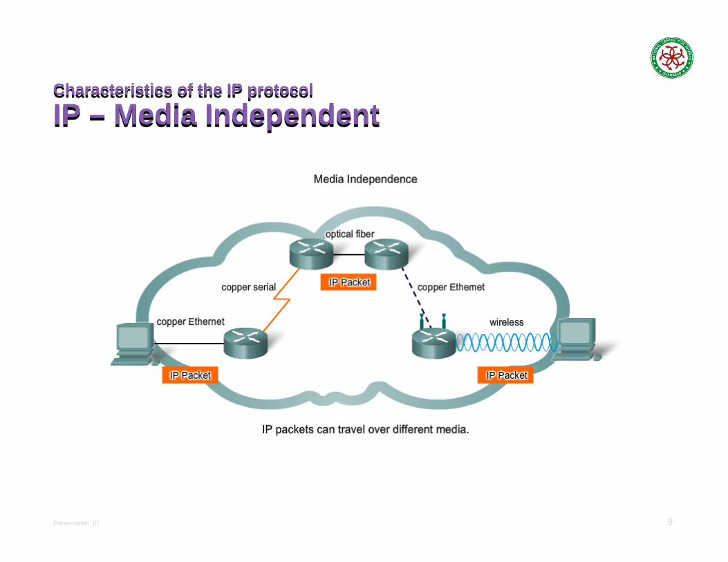
IP – Media IndependentCharacteristics of the IP protocol
IP – Media Independent

Presentation_ID 10
IPv4 Packet
Encapsulating IPIPv4 Packet
Encapsulating IP
Presentation_ID 11
IPv4 Packet
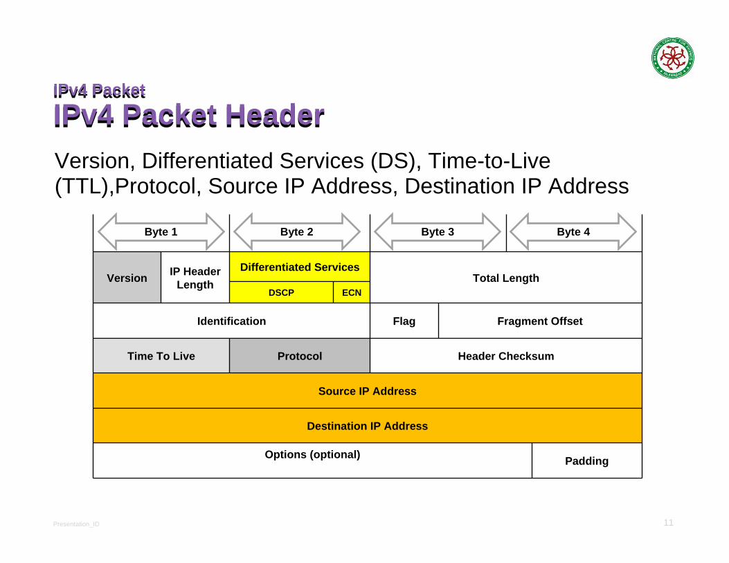
IPv4 Packet HeaderIPv4 Packet
IPv4 Packet HeaderVersion, Differentiated Services (DS), Time-to-Live (TTL),Protocol, Source IP Address, Destination IP Address
Version IP Header Length
Differentiated Services Total Length
DSCP ECN
Identification Flag Fragment Offset
Time To Live Protocol Header Checksum
Source IP Address
Destination IP Address
Options (optional) Padding
Byte 1 Byte 2 Byte 3 Byte 4
Presentation_ID 12
IPv4 Packet
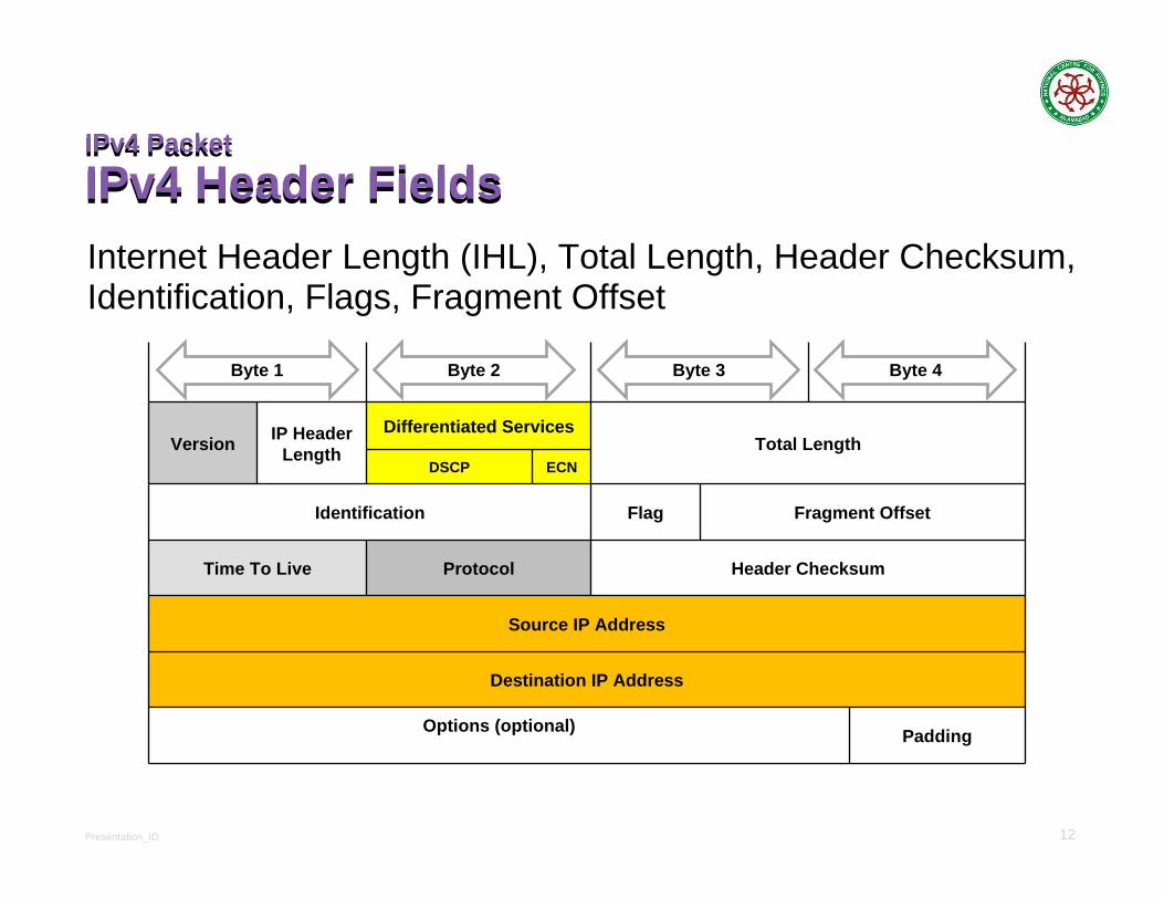
IPv4 Header FieldsIPv4 Packet
IPv4 Header FieldsInternet Header Length (IHL), Total Length, Header Checksum, Identification, Flags, Fragment Offset
Version IP Header Length
Differentiated Services Total Length
DSCP ECN
Identification Flag Fragment Offset
Time To Live Protocol Header Checksum
Source IP Address
Destination IP Address
Options (optional) Padding
Byte 1 Byte 2 Byte 3 Byte 4
Presentation_ID 13
IPv4 Packet
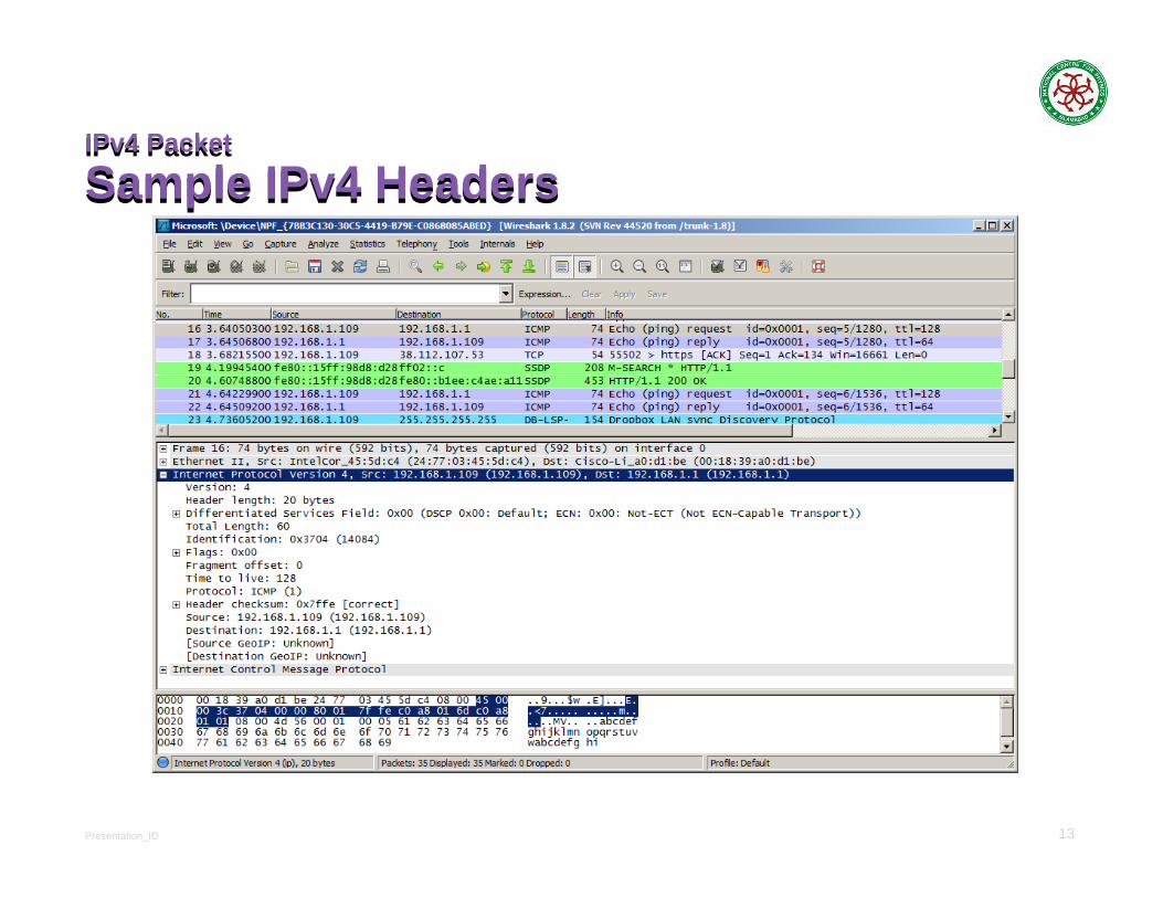
Sample IPv4 HeadersIPv4 Packet
Sample IPv4 Headers
Presentation_ID 14
Routing
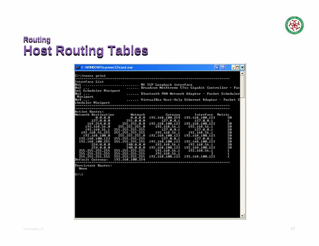
Host Routing TablesRouting
Host Routing Tables

Presentation_ID 15
Host Routing Tables
Host Packet Forwarding DecisionHost Routing Tables
Host Packet Forwarding Decision
Presentation_ID 16
Host Routing Tables
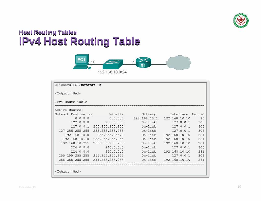
IPv4 Host Routing TableHost Routing Tables
IPv4 Host Routing Table
Presentation_ID 17
Host Routing Tables
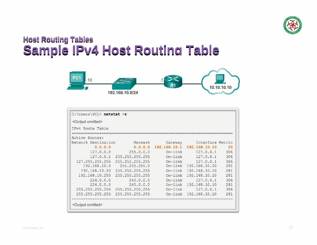
Sample IPv4 Host Routing TableHost Routing Tables
Sample IPv4 Host Routing Table
Presentation_ID 18
Router Routing Tables
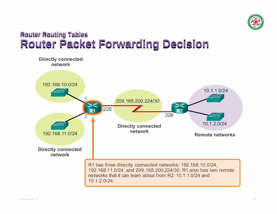
Router Packet Forwarding DecisionRouter Routing Tables
Router Packet Forwarding Decision

Presentation_ID 19
Configuring the Default Gateway
Default Gateway on a HostConfiguring the Default Gateway
Default Gateway on a Host192.168.10.0/24
192.168.11.0/24
G0/1.1
.1G0/0
R1
.10PC1
.10PC2
.10PC4
.10PC3
192.168.10.0/24
192.168.11.0/24
G0/1.1
.1G0/0
R1
.10PC1
.11PC2
.11PC4
.10PC3

© 2008 Cisco Systems, Inc. All rights reserved. Cisco ConfidentialPresentation_ID 20
IP AddressingIP Addressing
Network Basics

Presentation_ID 21
IPv4 Address Structure
Binary Number SystemIPv4 Address Structure
Binary Number System
128 + 64 = 192

Presentation_ID 22
IPv4 Address Structure
Converting a Binary Address to DecimalIPv4 Address Structure
Converting a Binary Address to DecimalPractice
Presentation_ID 23
IPv4 Address Structure
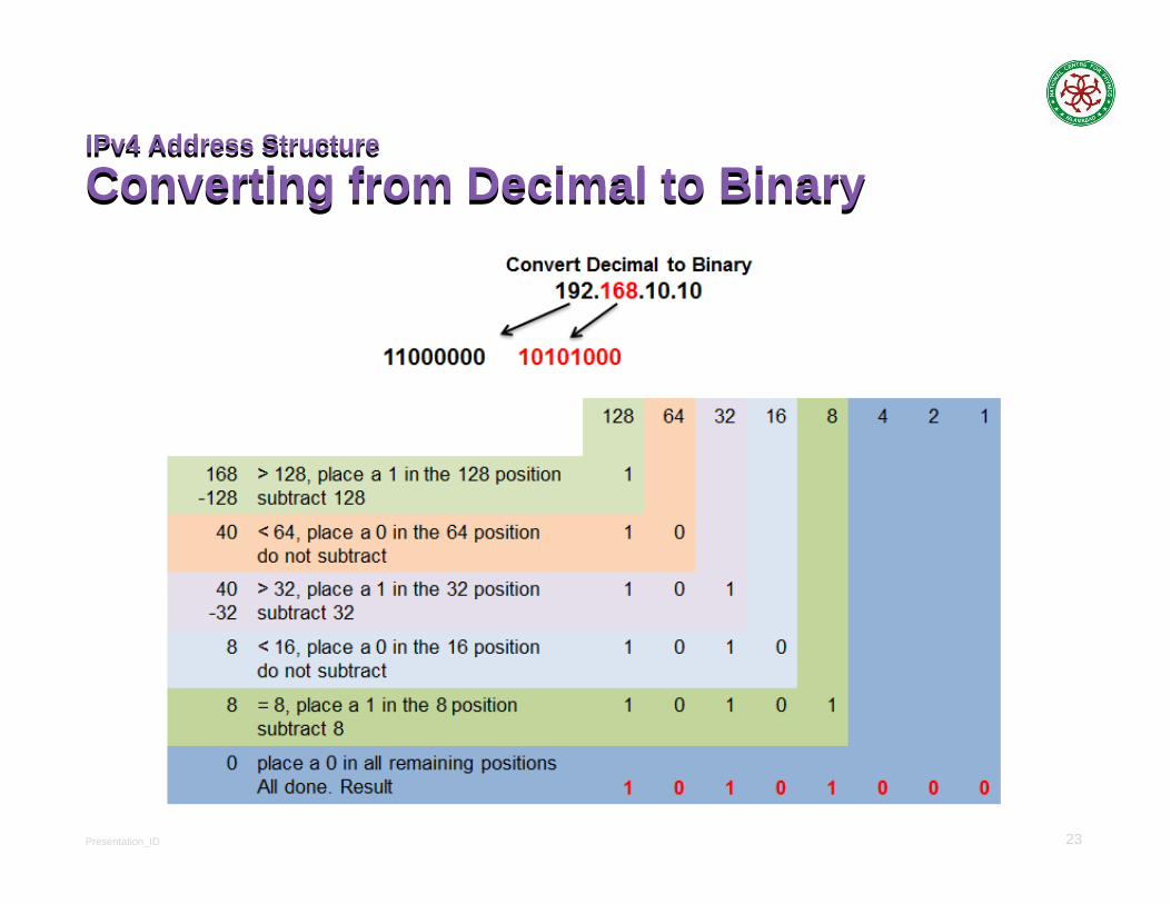
Converting from Decimal to BinaryIPv4 Address Structure
Converting from Decimal to Binary

Presentation_ID 24
Converting Decimal to BinaryConverting Decimal to Binary
Convert 20110 to binary:201 / 2 = 100 remainder 1100 / 2 = 50 remainder 050 / 2 = 25 remainder 025 / 2 = 12 remainder 112 / 2 = 6 remainder 06 / 2 = 3 remainder 03 / 2 = 1 remainder 11 / 2 = 0 remainder 1
When the quotient is 0, take all the remainders in reverse order for your answer: 20110 = 110010012

Presentation_ID 25
25
Binary to Decimal ChartBinary to Decimal Chart
Presentation_ID 26
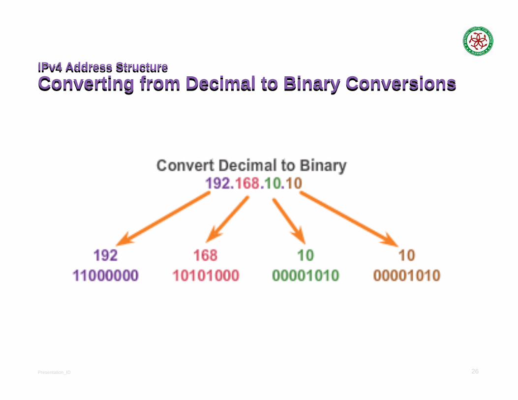
IPv4 Address StructureConverting from Decimal to Binary ConversionsIPv4 Address StructureConverting from Decimal to Binary Conversions
Presentation_ID 27
27
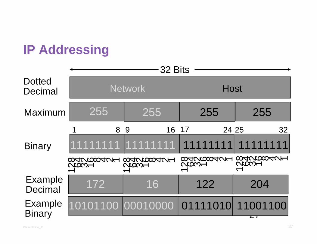
IP AddressingIP Addressing
255 255 255 255
DottedDecimal
Maximum
Network Host
128 64 32 16 8 4 2 1
11111111 11111111 11111111 11111111
10101100 00010000 01111010 11001100
Binary
32 Bits
172 16 122 204ExampleDecimalExampleBinary
1 8 9 16 17 24 25 32
128 64 32 16 8 4 2 1
128 64 32 16 8 4 2 1
128 64 32 16 8 4 2 1
Presentation_ID 28
Classful Addressing
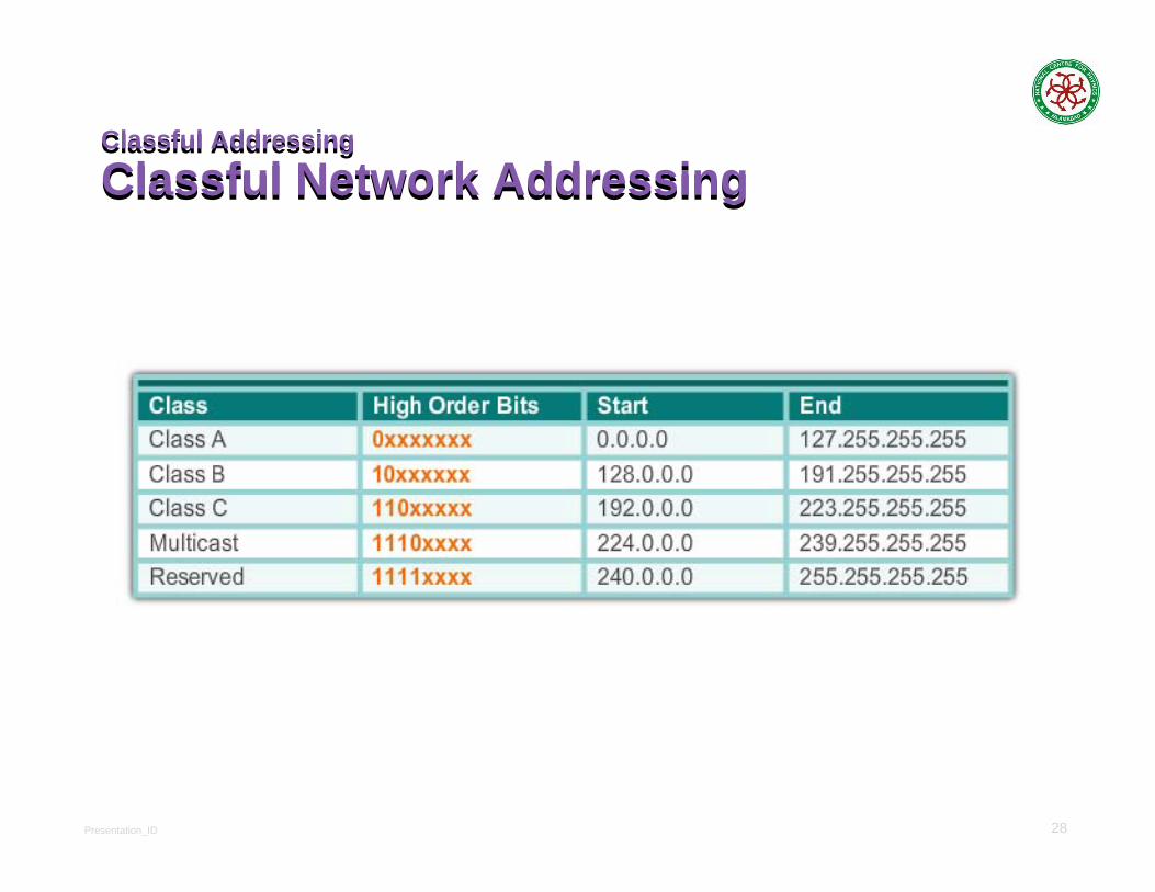
Classful Network AddressingClassful Addressing
Classful Network Addressing

Presentation_ID 29
Classful Addressing
Classful Subnet MasksClassful Addressing
Classful Subnet MasksClass A
Class B
Class C

Presentation_ID 30
30
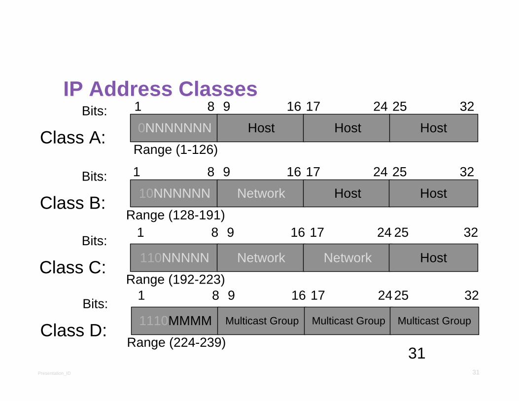
Class A:
Class B:
Class C:
Class D: Multicast
Class E: Research
IP Address ClassesIP Address Classes
NetworkNetwork HostHost HostHost HostHost
NetworkNetwork NetworkNetwork HostHost HostHost
NetworkNetwork NetworkNetwork NetworkNetwork HostHost
8 Bits 8 Bits 8 Bits 8 Bits
Presentation_ID 31
31
IP Address ClassesIP Address Classes1
Class A:Bits:
0NNNNNNN0NNNNNNN HostHost HostHost HostHost8 9 16 17 24 25 32
Range (1-126)
1
Class B:Bits:
10NNNNNN10NNNNNN NetworkNetwork HostHost HostHost8 9 16 17 24 25 32
Range (128-191)1
Class C:Bits:
110NNNNN110NNNNN NetworkNetwork NetworkNetwork HostHost
8 9 16 17 24 25 32
Range (192-223)1
Class D:Bits:
1110MMMM1110MMMM Multicast GroupMulticast Group Multicast GroupMulticast Group Multicast GroupMulticast Group
8 9 16 17 2425 32
Range (224-239)

Presentation_ID 32
IPv4 Subnet MaskNetwork Portion and Host Portion of an IPv4 AddressIPv4 Subnet MaskNetwork Portion and Host Portion of an IPv4 Address
To define the network and host portions of an address, a devices use a separate 32-bit pattern called a subnet maskThe subnet mask does not actually contain the network or host portion of an IPv4 address, it just says where to look for these portions in a given IPv4 address

Presentation_ID 33
IPv4 Unicast, Broadcast, and Multicast
Assigning a Static IPv4 Address to a HostIPv4 Unicast, Broadcast, and Multicast
Assigning a Static IPv4 Address to a Host

Presentation_ID 34
IPv4 Unicast, Broadcast, and MulticastAssigning a Dynamic IPv4 Address to a HostIPv4 Unicast, Broadcast, and MulticastAssigning a Dynamic IPv4 Address to a Host
Verification
DHCP - preferred method of “leasing” IPv4 addresses to hosts on large networks, reduces the burden on network support staff and virtually eliminates entry errors

Presentation_ID 35
IPv4 Subnet MaskNetwork Portion and Host Portion of an IPv4 AddressIPv4 Subnet MaskNetwork Portion and Host Portion of an IPv4 Address
Valid Subnet Masks

Presentation_ID 36
36
CIDR ValuesCIDR Values
Presentation_ID 37
IPv4 Subnet Mask
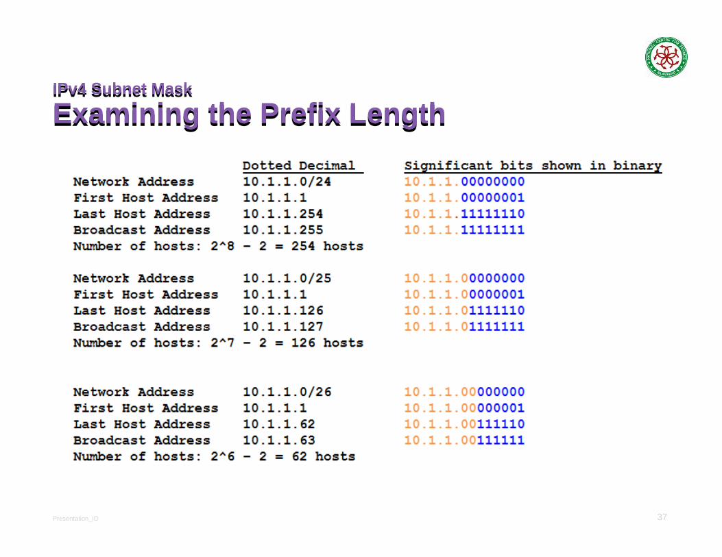
Examining the Prefix LengthIPv4 Subnet Mask
Examining the Prefix Length

Presentation_ID 38
IPv4 Subnet Mask
Network, Host, and Broadcast AddressIPv4 Subnet Mask
Network, Host, and Broadcast Address
Presentation_ID 39
IPv4 Subnet Mask
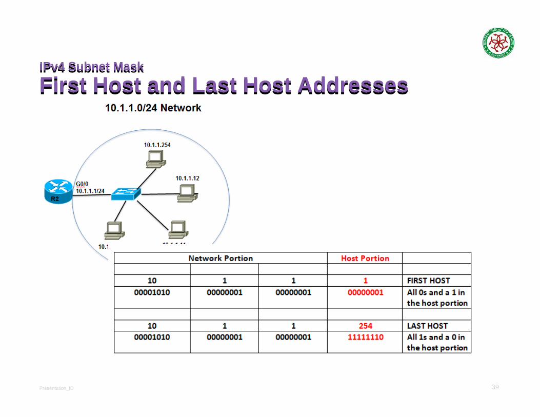
First Host and Last Host AddressesIPv4 Subnet Mask
First Host and Last Host Addresses

Presentation_ID 40
IPv4 Subnet Mask
Bitwise AND OperationIPv4 Subnet Mask
Bitwise AND Operation
1 AND 1 = 1 1 AND 0 = 0 0 AND 1 = 0 0 AND 0 = 0

Presentation_ID 41
Types of IPv4 Address
Public and Private IPv4 AddressesTypes of IPv4 Address
Public and Private IPv4 AddressesPrivate address blocks are:
Hosts that do not require access to the Internet can use private addresses
10.0.0.0 to 10.255.255.255 (10.0.0.0/8)
172.16.0.0 to 172.31.255.255 (172.16.0.0/12)
192.168.0.0 to 192.168.255.255 (192.168.0.0/16)
Shared address space addresses:
Not globally routable
Intended only for use in service provider networks
Address block is 100.64.0.0/10

Presentation_ID 42
Types of IPv4 Address
Special Use IPv4 AddressesTypes of IPv4 Address
Special Use IPv4 AddressesNetwork and Broadcast addresses - within each network the first and last addresses cannot be assigned to hosts
Loopback address - 127.0.0.1 a special address that hosts use to direct traffic to themselves (addresses 127.0.0.0 to 127.255.255.255 are reserved)
Link-Local address - 169.254.0.0 to 169.254.255.255 (169.254.0.0/16) addresses can be automatically assigned to the local host
TEST-NET addresses - 192.0.2.0 to 192.0.2.255 (192.0.2.0/24) set aside for teaching and learning purposes, used in documentation and network examples
Experimental addresses - 240 0 0 0 to 255 255 255 254

Presentation_ID 43
Types of IPv4 Address
Legacy Classful AddressingTypes of IPv4 Address
Legacy Classful Addressing
Classless AddressingFormal name is Classless Inter-Domain Routing (CIDR,
pronounced “ciderCreated a new set of standards that allowed service
providers to allocate IPv4 addresses on any address bit boundary (prefix length) instead of only by a class A, B, or C address

Presentation_ID 44
Types of IPv4 Address
Assignment of IP AddressesTypes of IPv4 Address
Assignment of IP AddressesRegional Internet Registries (RIRs)The major registries are:

Presentation_ID 45
Types of IPv4 Address
Assignment of IP AddressesTypes of IPv4 Address
Assignment of IP Addresses
Tier 2 ISPs generally focus on business customers.
Tier 3 ISPs purchase their Internet service from Tier 2 ISPs.
Tier 3 ISPs often bundle Internet connectivity as a part of network and computer service contracts for their customers.
ISPs are large national or international ISPs that are directly connected to the Internet backbone.

Presentation_ID 46
46
Binary to Decimal ChartBinary to Decimal Chart
Presentation_ID 47
47
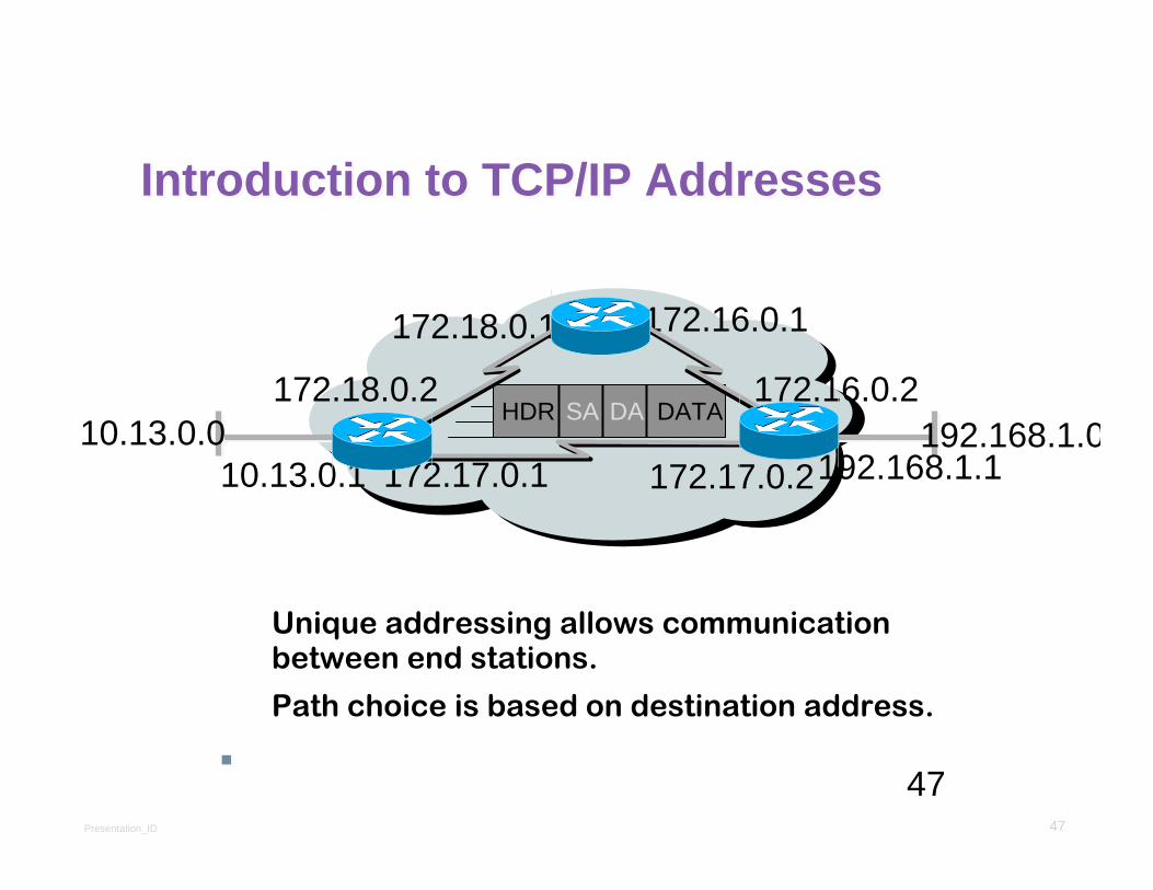
Unique addressing allows communication between end stations.
Path choice is based on destination address.
Location is represented by an address
Introduction to TCP/IP AddressesIntroduction to TCP/IP Addresses
172.18.0.2
172.18.0.1
172.17.0.2172.17.0.1
172.16.0.2
172.16.0.1
SA DAHDR DATA10.13.0.0 192.168.1.0
10.13.0.1 192.168.1.1

Presentation_ID 48
Types of IPv4 Address
Public and Private IPv4 AddressesTypes of IPv4 Address
Public and Private IPv4 AddressesPrivate address blocks are:
Hosts that do not require access to the Internet can use private addresses
10.0.0.0 to 10.255.255.255 (10.0.0.0/8)
172.16.0.0 to 172.31.255.255 (172.16.0.0/12)
192.168.0.0 to 192.168.255.255 (192.168.0.0/16)
Shared address space addresses:
Not globally routable
Intended only for use in service provider networks
Address block is 100.64.0.0/10
Presentation_ID 49
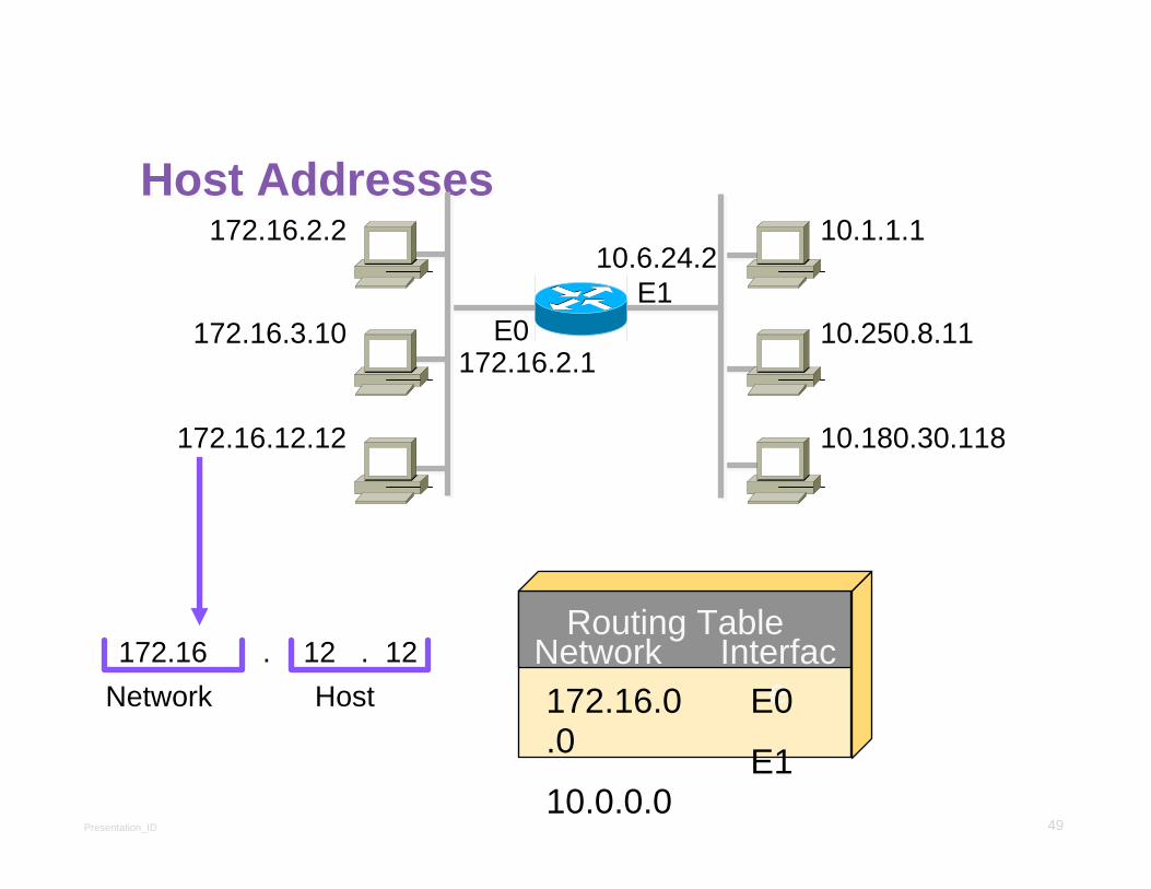
Host AddressesHost Addresses172.16.2.2
172.16.3.10
172.16.12.12
10.1.1.1
10.250.8.11
10.180.30.118
E1
172.16 12 12Network Host
. . Network Interface172.16.0
.0
10.0.0.0
E0
E1
Routing Table
172.16.2.1
10.6.24.2
E0
Presentation_ID 50
50
Classless Inter-Domain Routing (CIDR)Classless Inter-Domain Routing (CIDR)Basically the method that ISPs (Internet Service Providers) use to allocate an amount of addresses to a company, a home
Ex : 192.168.10.32/28
The slash notation (/) means how many bits are turned on (1s)
Presentation_ID 51
51
11111111
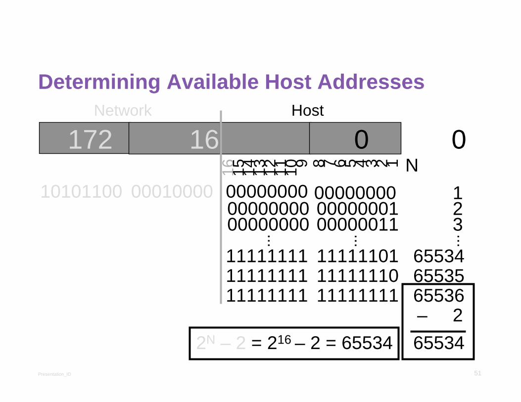
Determining Available Host AddressesDetermining Available Host Addresses
172 16 0 0
10101100 00010000 00000000 00000000
16 15 14 13 12 11 10 9 8 7 6 5 4 3 2 1
Network Host
00000000 00000001
11111111 1111111111111111 11111110
......
00000000 00000011
11111101
123
655346553565536–
...
265534
N
2N – 2 = 216 – 2 = 65534

Presentation_ID 52
52
IP Address Classes ExerciseIP Address Classes Exercise
Address Class Network Host
10.2.1.1
128.63.2.100201.222.5.64192.6.141.2
130.113.64.16256.241.201.10

Presentation_ID 53
53
IP Address Classes Exercise AnswersIP Address Classes Exercise Answers
Address Class Network Host
10.2.1.1128.63.2.100201.222.5.64
192.6.141.2130.113.64.16256.241.201.10
A
B
C
CB
Nonexistent
10.0.0.0128.63.0.0201.222.5.0192.6.141.0130.113.0.0
0.2.1.10.0.2.100
0.0.0.64
0.0.0.20.0.64.16

Presentation_ID 54
Classful Addressing
Classful Addressing WasteClassful Addressing
Classful Addressing Waste
Presentation_ID 55
CIDR
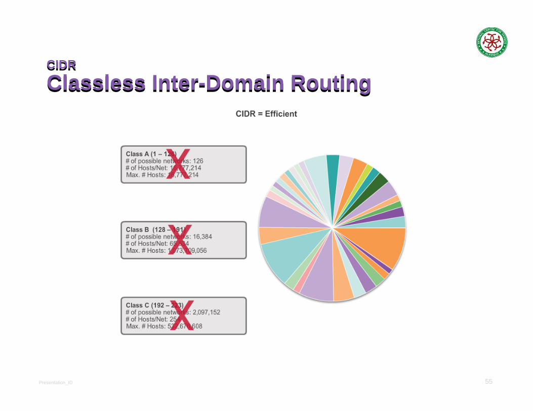
Classless Inter-Domain RoutingCIDR
Classless Inter-Domain Routing

Presentation_ID 56
Network Segmentation
Reasons for SubnettingNetwork Segmentation
Reasons for SubnettingLarge networks need to be segmented into smaller sub-
networks, creating smaller groups of devices and services in order to:
Control traffic by containing broadcast traffic within subnetwork
Reduce overall network traffic and improve network performance
Subnetting - process of segmenting a network into multiple smaller network spaces called subnetworks or Subnets.
Communication Between Subnets
A router is necessary for devices on different networks and subnets to communicate.
Each router interface must have an IPv4 host address that belongs to the network or subnet that the router interface is connected to.
Devices on a network and subnet use the router interface attached to their LAN as their default gateway.
Presentation_ID 57
Subnetting an IPv4 Network
Basic SubnettingSubnetting an IPv4 Network
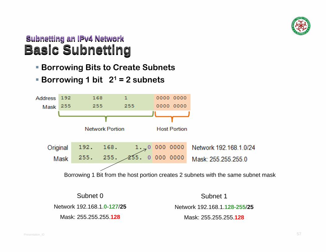
Basic SubnettingBorrowing Bits to Create Subnets
Borrowing 1 bit 21 = 2 subnets
Subnet 1Network 192.168.1.128-255/25
Mask: 255.255.255.128
Subnet 0Network 192.168.1.0-127/25
Mask: 255.255.255.128
Borrowing 1 Bit from the host portion creates 2 subnets with the same subnet mask

Presentation_ID 58
Subnetting an IPv4 Network
Subnets in UseSubnetting an IPv4 Network
Subnets in Use
Subnet 0
Network 192.168.1.0-127/25
Subnet 1
Network 192.168.1.128-255/25
Presentation_ID 59
Subnetting an IPv4 Network
Subnetting FormulasSubnetting an IPv4 Network
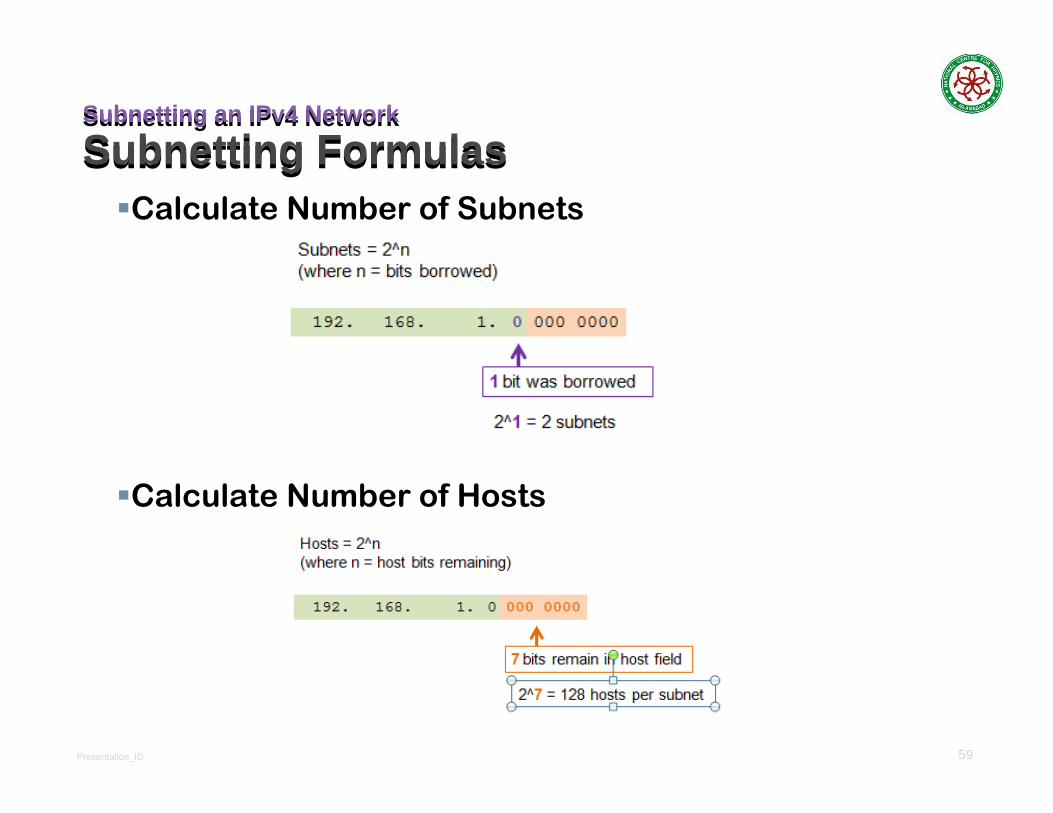
Subnetting FormulasCalculate Number of Subnets
Calculate Number of Hosts

Presentation_ID 60
Subnetting an IPv4 Network
Creating 4 SubnetsSubnetting an IPv4 Network
Creating 4 SubnetsBorrowing 2 bits to create 4 subnets. 22 = 4 subnets

Presentation_ID 61
Subnetting an IPv4 Network
Creating 8 SubnetsSubnetting an IPv4 Network
Creating 8 SubnetsBorrowing 3 bits to Create 8 Subnets. 23 = 8 subnets
Presentation_ID 62
Subnetting an IPv4 Network
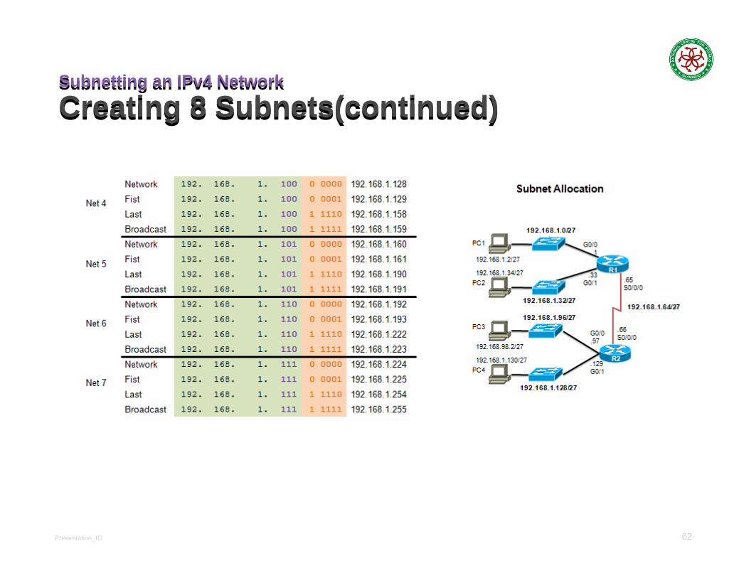
Creating 8 Subnets(continued)Subnetting an IPv4 Network
Creating 8 Subnets(continued)
Presentation_ID 63
Determining the Subnet Mask
Subnetting Based on Host RequirementsDetermining the Subnet Mask
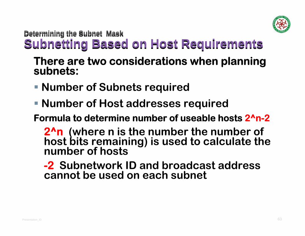
Subnetting Based on Host RequirementsThere are two considerations when planning subnets:
Number of Subnets required
Number of Host addresses requiredFormula to determine number of useable hosts 2^n-2
2^n (where n is the number the number of host bits remaining) is used to calculate the number of hosts-2 Subnetwork ID and broadcast address cannot be used on each subnet
Presentation_ID 64
Determining the Subnet MaskSubnetting Based on Network RequirementsDetermining the Subnet MaskSubnetting Based on Network Requirements
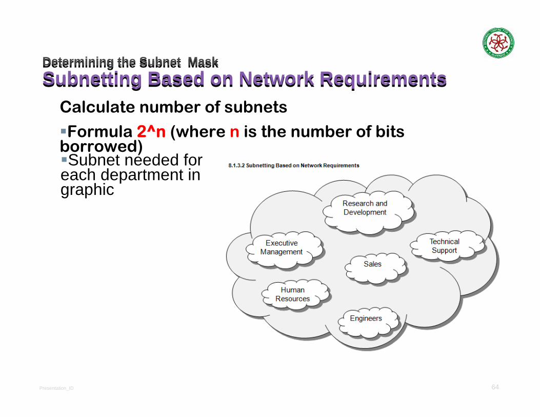
Calculate number of subnets
Formula 2^n (where n is the number of bits borrowed)Subnet needed for
each department in graphic

Presentation_ID 65
Determining the Subnet MaskSubnetting To Meet Network RequirementsDetermining the Subnet MaskSubnetting To Meet Network Requirements
It is important to balance the number of subnets needed and the number of hosts required for the largest subnet.
Design the addressing scheme to accommodate the maximum number of hosts for each subnet.
Allow for growth in each subnet.

Presentation_ID 66
Determining the Subnet MaskSubnetting To Meet Network Requirements (cont)Determining the Subnet MaskSubnetting To Meet Network Requirements (cont)
Presentation_ID 67
Benefits of Variable Length Subnet MaskingTraditional Subnetting Wastes AddressesBenefits of Variable Length Subnet MaskingTraditional Subnetting Wastes Addresses
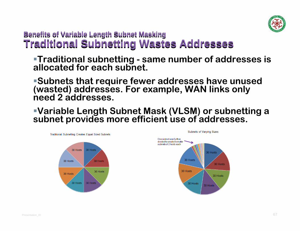
Traditional subnetting - same number of addresses is allocated for each subnet.
Subnets that require fewer addresses have unused (wasted) addresses. For example, WAN links only need 2 addresses.
Variable Length Subnet Mask (VLSM) or subnetting a subnet provides more efficient use of addresses.
Presentation_ID 68
Benefits of Variable Length Subnet MaskingVariable Length Subnet Masks (VLSM)Benefits of Variable Length Subnet MaskingVariable Length Subnet Masks (VLSM)
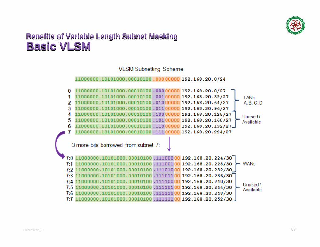
VLSM allows a network space to be divided in unequal parts.
Subnet mask will vary depending on how many bits have been borrowed for a particular subnet.
Network is first subnetted, and then the subnets are subnetted again.
Process repeated as necessary to create subnets of various sizes.
Presentation_ID 69
Benefits of Variable Length Subnet MaskingBasic VLSMBenefits of Variable Length Subnet MaskingBasic VLSM
Presentation_ID 70
Benefits of Variable Length Subnet MaskingVLSM in PracticeBenefits of Variable Length Subnet MaskingVLSM in Practice
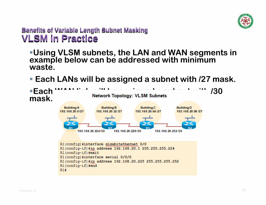
Using VLSM subnets, the LAN and WAN segments in example below can be addressed with minimum waste.
Each LANs will be assigned a subnet with /27 mask.
Each WAN link will be assigned a subnet with /30 mask.

Presentation_ID 71
Benefits of Variable Length Subnet MaskingVLSM ChartBenefits of Variable Length Subnet MaskingVLSM Chart
Presentation_ID 72
Structured DesignPlanning to Address the NetworkStructured DesignPlanning to Address the Network
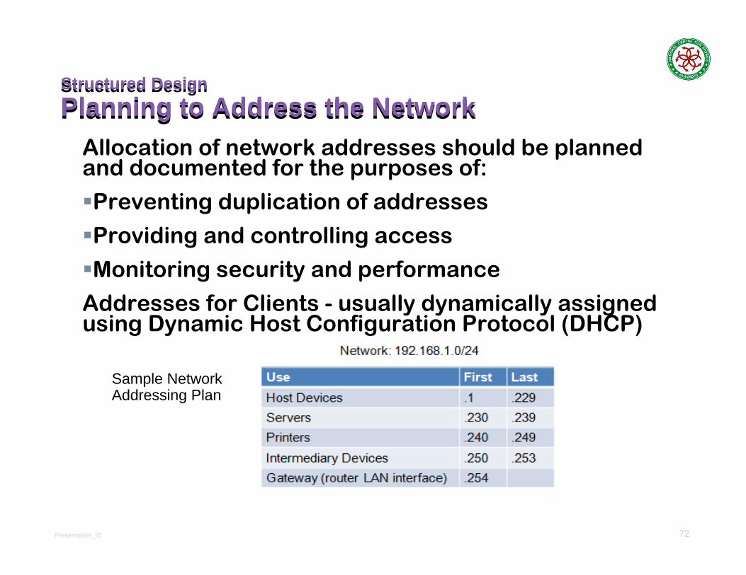
Allocation of network addresses should be planned and documented for the purposes of:
Preventing duplication of addresses
Providing and controlling access
Monitoring security and performance
Addresses for Clients - usually dynamically assigned using Dynamic Host Configuration Protocol (DHCP)
Sample Network Addressing Plan
Presentation_ID 73
73
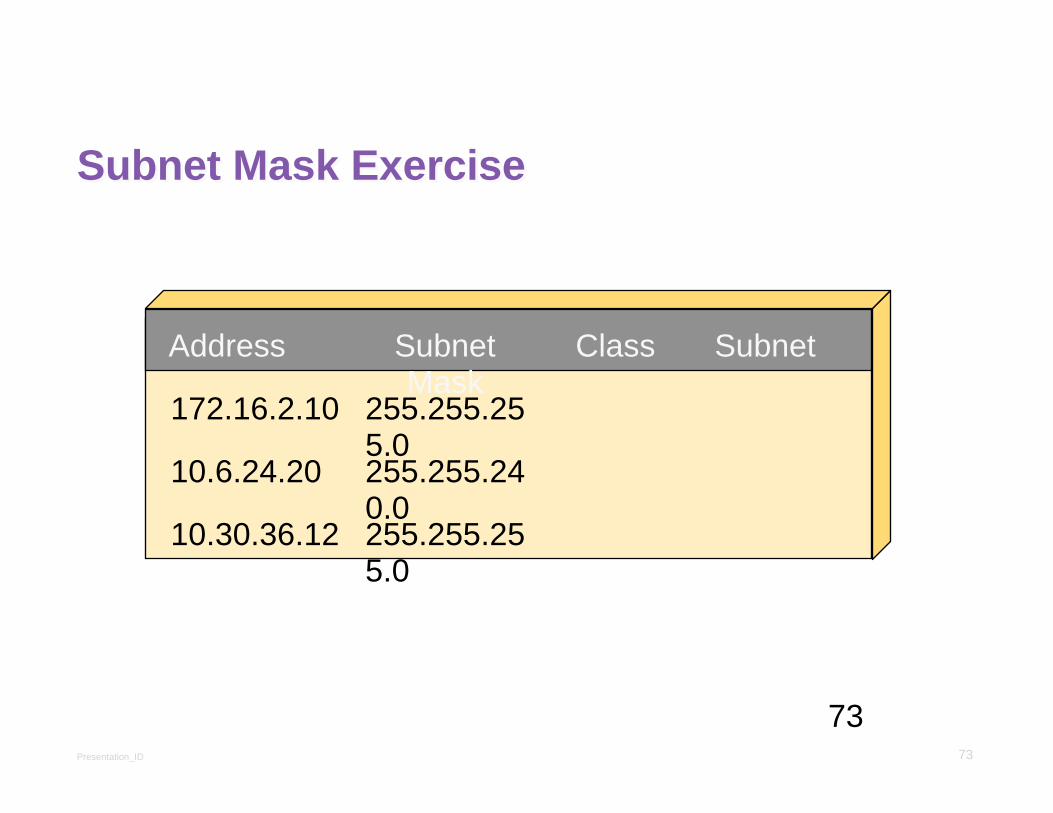
Subnet Mask ExerciseSubnet Mask Exercise
Address Subnet Mask
Class Subnet
172.16.2.10
10.6.24.20
10.30.36.12
255.255.255.0255.255.240.0255.255.255.0

Presentation_ID 74
74
Subnet Mask Exercise AnswersSubnet Mask Exercise Answers
Address Subnet Mask Class Subnet
172.16.2.10
10.6.24.20
10.30.36.12
255.255.255.0255.255.240.0255.255.255.0
B
A
A
172.16.2.0
10.6.16.0
10.30.36.0
Presentation_ID 75
75
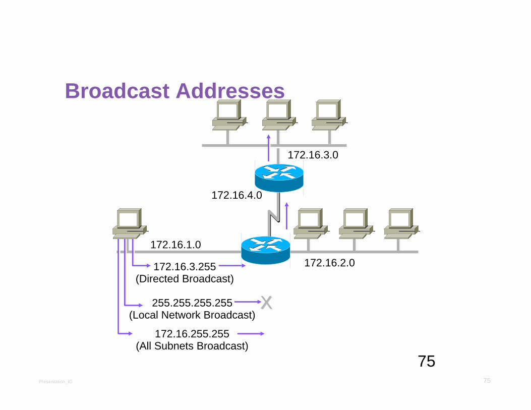
Broadcast AddressesBroadcast Addresses
172.16.1.0
172.16.2.0
172.16.3.0
172.16.4.0
172.16.3.255(Directed Broadcast)
255.255.255.255(Local Network Broadcast)
XX172.16.255.255
(All Subnets Broadcast)
Presentation_ID 76
76
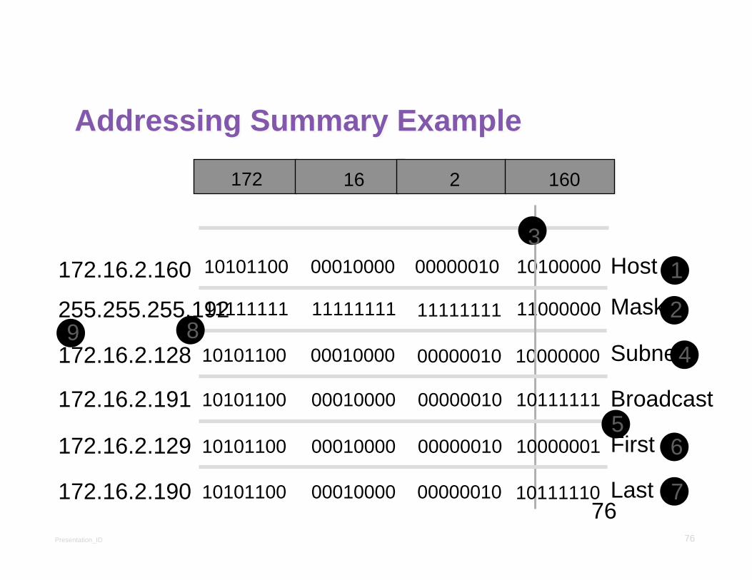
Addressing Summary ExampleAddressing Summary Example
10101100
11111111
10101100
00010000
11111111
00010000
11111111
00000010
10100000
11000000
10000000
00000010
10101100 00010000 00000010 10111111
10101100 00010000 00000010 10000001
10101100 00010000 00000010 10111110
Host
Mask
Subnet
Broadcast
Last
First
172.16.2.160
255.255.255.192
172.16.2.128
172.16.2.191
172.16.2.129
172.16.2.190
1
2
3
4
56
7
89
16172 2 160

Presentation_ID 77
77
IP Host Address: 172.16.2.121Subnet Mask: 255.255.255.0
Subnet Address = 172.16.2.0
Host Addresses = 172.16.2.1–172.16.2.254
Broadcast Address = 172.16.2.255
Eight Bits of Subnetting
Network Subnet Host
10101100 00010000 00000010 11111111
172.16.2.121:
255.255.255.0:
1010110011111111
Subnet: 10101100 00010000
0001000011111111
00000010
00000010
1111111101111001 00000000
00000000
Class B Subnet ExampleClass B Subnet Example
Broadcast:
Network
Presentation_ID 78
78
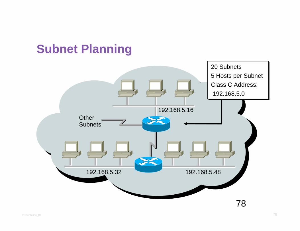
Subnet PlanningSubnet Planning
Other Subnets
192.168.5.16
192.168.5.32 192.168.5.48
20 Subnets5 Hosts per SubnetClass C Address:192.168.5.0
20 Subnets5 Hosts per SubnetClass C Address:192.168.5.0

Presentation_ID 79
79
11111000
IP Host Address: 192.168.5.121Subnet Mask: 255.255.255.248
Network Subnet Host
192.168.5.121: 1100000011111111
Subnet: 11000000 10101000
1010100011111111
00000101
00000101
1111111101111001
01111000
255.255.255.248:
Class C Subnet Planning ExampleClass C Subnet Planning Example
Subnet Address = 192.168.5.120
Host Addresses = 192.168.5.121–192.168.5.126
Broadcast Address = 192.168.5.127
Five Bits of Subnetting
Broadcast:
NetworkNetwork
11000000 10101000 00000101 01111111
Presentation_ID 80
80
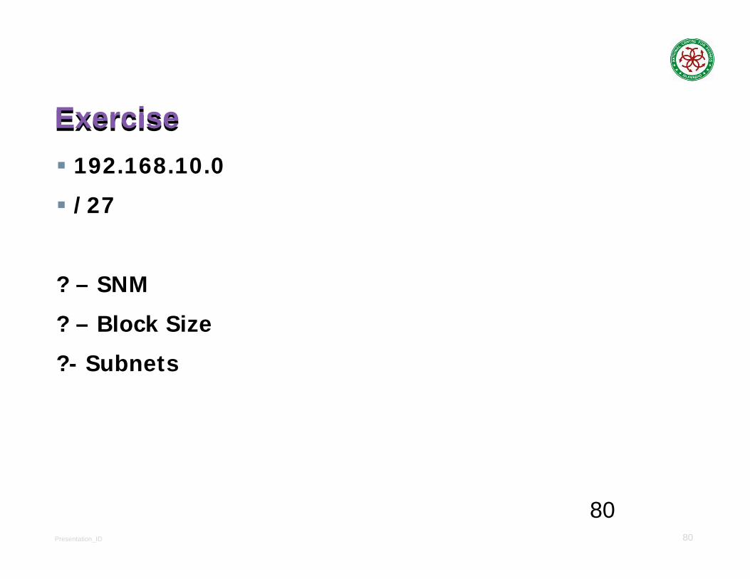
ExerciseExercise192.168.10.0
/27
? – SNM
? – Block Size
?- Subnets

Presentation_ID 81
81
ExerciseExercise/27
? – SNM – 224
? – Block Size = 256-224 = 32
?- SubnetsSubnets 10.0 10.32 10.64
FHID 10.1 10.33
LHID 10.30 10.62
Broadcast 10.31 10.63

Presentation_ID 82
82
ExerciseExercise192.168.10.0
/30
? – SNM
? – Block Size
?- Subnets

Presentation_ID 83
83
ExerciseExercise/30
? – SNM – 252
? – Block Size = 256-252 = 4
?- SubnetsSubnets 10.0 10.4 10.8
FHID 10.1 10.5
LHID 10.2 10.6
Broadcast 10.3 10.7

Presentation_ID 84
84
ExerciseExerciseMask Subnets Host
/26 ? ? ?/27 ? ? ?/28 ? ? ?/29 ? ? ?/30 ? ? ?
Presentation_ID 85
85
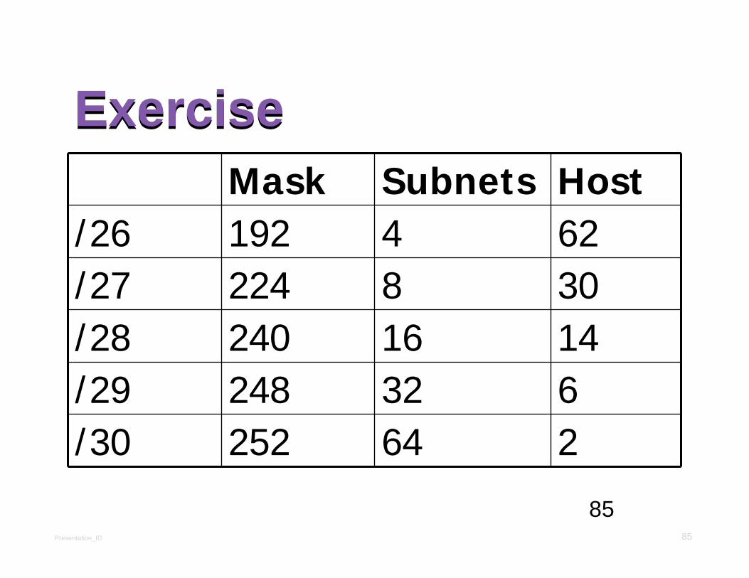
ExerciseExerciseMask Subnets Host
/26 192 4 62/27 224 8 30/28 240 16 14/29 248 32 6/30 252 64 2

Presentation_ID 86
86
Exam QuestionExam QuestionFind Subnet and Broadcast address
192.168.0.100/27
Presentation_ID 87
87
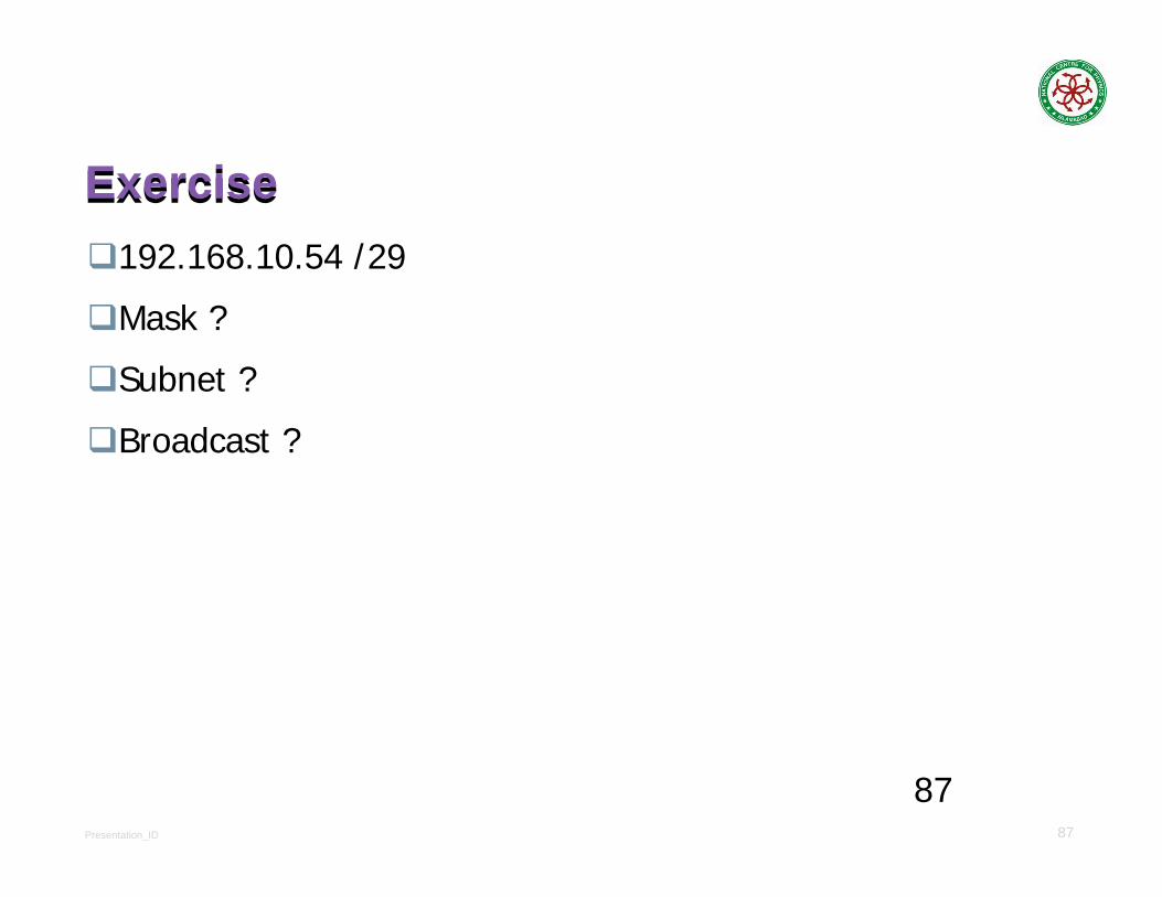
ExerciseExercise192.168.10.54 /29
Mask ?
Subnet ?
Broadcast ?

Presentation_ID 88
88
ExerciseExercise192.168.10.130 /28
Mask ?
Subnet ?
Broadcast ?

Presentation_ID 89
89
ExerciseExercise192.168.10.193 /30
Mask ?
Subnet ?
Broadcast ?

Presentation_ID 90
90
ExerciseExercise192.168.1.100 /26
Mask ?
Subnet ?
Broadcast ?

Presentation_ID 91
91
ExerciseExercise192.168.20.158 /27
Mask ?
Subnet ?
Broadcast ?

Presentation_ID 92
92
Class BClass B172.16.0.0 /19
Subnets ?
Hosts ?
Block Size ?

Presentation_ID 93
93
Class BClass B172.16.0.0 /19
Subnets 23 -2 = 6
Hosts 213 -2 = 8190
Block Size 256-224 = 32Subnets 0.0 32.0 64.0 96.0
FHID 0.1 32.1 64.1 96.1
LHID 31.254 63.254 95.254 127.254
Broadcast 31.255 63.255 95.255 127.255

Presentation_ID 94
94
Class BClass B172.16.0.0 /27
Subnets ?
Hosts ?
Block Size ?
Presentation_ID 95
95
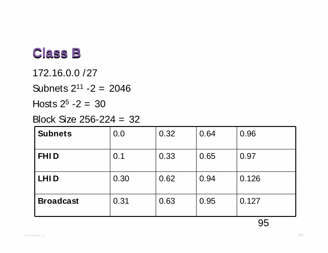
Class BClass B172.16.0.0 /27
Subnets 211 -2 = 2046
Hosts 25 -2 = 30
Block Size 256-224 = 32Subnets 0.0 0.32 0.64 0.96
FHID 0.1 0.33 0.65 0.97
LHID 0.30 0.62 0.94 0.126
Broadcast 0.31 0.63 0.95 0.127

Presentation_ID 96
96
Class BClass B172.16.0.0 /23
Subnets ?
Hosts ?
Block Size ?

Presentation_ID 97
97
Class BClass B172.16.0.0 /23
Subnets 27 -2 = 126
Hosts 29 -2 = 510
Block Size 256-254 = 2
Subnets 0.0 2.0 4.0 6.0
FHID 0.1 2.1 4.1 6.1
LHID 1.254 3.254 5.254 7.254
Broadcast 1.255 3.255 5.255 7.255

Presentation_ID 98
98
Class BClass B172.16.0.0 /24
Subnets ?
Hosts ?
Block Size ?

Presentation_ID 99
99
Class BClass B172.16.0.0 /24
Subnets 28 -2 = 254
Hosts 28 -2 = 254
Block Size 256-255 = 1
Subnets 0.0 1.0 2.0 3.0
FHID 0.1 1.1 2.1 3.1
LHID 0.254 1.254 2.254 3.254
Broadcast 0.255 1.255 2.255 3.255
Presentation_ID 100
100
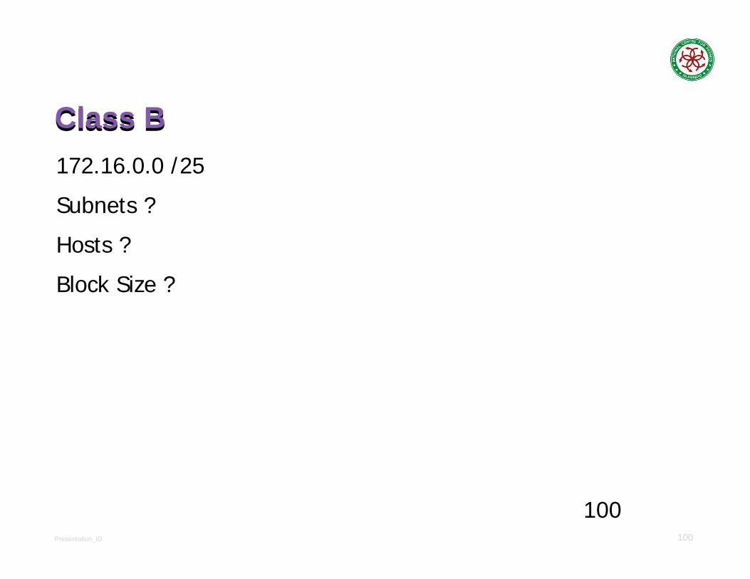
Class BClass B172.16.0.0 /25
Subnets ?
Hosts ?
Block Size ?

Presentation_ID 101
101
Class BClass B172.16.0.0 /25
Subnets 29 -2 = 510
Hosts 27 -2 = 126
Block Size 256-128 = 128
Subnets 0.0 0.128 1.0 1.128 2.0 2.128
FHID 0.1 0.129 1.1 1.129 2.1 2.129
LHID 0.126 0.254 1.126 1.254 2.126 2.254
Broadcast 0.127 0.255 1.127 1.255 2.127 2.255
Presentation_ID 102
102
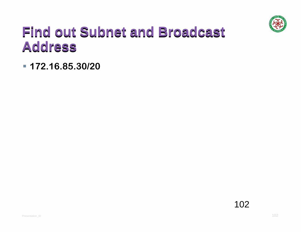
Find out Subnet and Broadcast AddressFind out Subnet and Broadcast Address
172.16.85.30/20

Presentation_ID 103
103
Find out Subnet and Broadcast AddressFind out Subnet and Broadcast Address
172.16.85.30/29

Presentation_ID 104
104
Find out Subnet and Broadcast AddressFind out Subnet and Broadcast Address
172.30.101.62/23

Presentation_ID 105
105
Find out Subnet and Broadcast AddressFind out Subnet and Broadcast Address
172.20.210.80/24
Presentation_ID 106
106
ExerciseExerciseFind out the mask which gives 100 subnets for class B

Presentation_ID 107
107
ExerciseExerciseFind out the Mask which gives 100 hosts for Class B

Presentation_ID 108
108
Class AClass A10.0.0.0 /10
Subnets ?
Hosts ?
Block Size ?
Presentation_ID 109
109
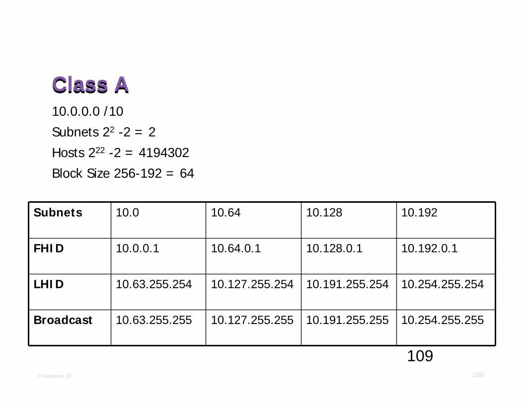
Class AClass A10.0.0.0 /10
Subnets 22 -2 = 2
Hosts 222 -2 = 4194302
Block Size 256-192 = 64
Subnets 10.0 10.64 10.128 10.192
FHID 10.0.0.1 10.64.0.1 10.128.0.1 10.192.0.1
LHID 10.63.255.254 10.127.255.254 10.191.255.254 10.254.255.254
Broadcast 10.63.255.255 10.127.255.255 10.191.255.255 10.254.255.255

Presentation_ID 110
110
Class AClass A10.0.0.0 /18
Subnets ?
Hosts ?
Block Size ?

Presentation_ID 111
111
Class AClass A10.0.0.0 /18
Subnets 210 -2 = 1022
Hosts 214 -2 = 16382
Block Size 256-192 = 64
Subnets 10.0.0.0 10.0.64.0 10.0.128.0 10.0.192.0
FHID 10.0.0.1 10.0.64.1 10.0.128.1 10.0.192.1
LHID 10.0.63.254 10.0.127.254 10.0.191.254 10.0.254.254
Broadcast 10.0.63.255 10.0.127.255 10.0.191.255 10.0.254.255
© 2008 Cisco Systems, Inc. All rights reserved. Cisco ConfidentialPresentation_ID 112
Network AccessNetwork Access
Network Basics

Presentation_ID 113
Purpose of the Data Link Layer
The Data Link LayerPurpose of the Data Link Layer
The Data Link Layer

Presentation_ID 114
Ethernet Operation
LLC and MAC SublayersEthernet Operation
LLC and MAC Sublayers

Presentation_ID 115
Purpose of the Data Link Layer
Data Link SublayersPurpose of the Data Link Layer
Data Link Sublayers
Network
Data Link
LLC Sublayer
MAC Sublayer
Physical
Presentation_ID 116
Ethernet Operation
LLC and MAC SublayersEthernet Operation
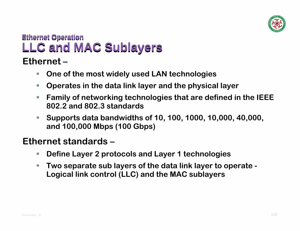
LLC and MAC SublayersEthernet –
One of the most widely used LAN technologies
Operates in the data link layer and the physical layer
Family of networking technologies that are defined in the IEEE 802.2 and 802.3 standards
Supports data bandwidths of 10, 100, 1000, 10,000, 40,000, and 100,000 Mbps (100 Gbps)
Ethernet standards –Define Layer 2 protocols and Layer 1 technologies
Two separate sub layers of the data link layer to operate -Logical link control (LLC) and the MAC sublayers
Presentation_ID 117
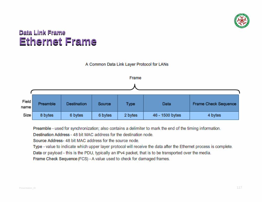
Data Link Frame
Ethernet FrameData Link Frame
Ethernet Frame

Presentation_ID 118
Ethernet Frame AttributesEthernet EncapsulationEthernet Frame AttributesEthernet Encapsulation
Early versions of Ethernet were relatively slow at 10 MbpsNow operate at 10 Gigabits per second and fasterEthernet frame structure adds headers and trailers around the Layer 3 PDU to encapsulate the message being sent
Presentation_ID 119
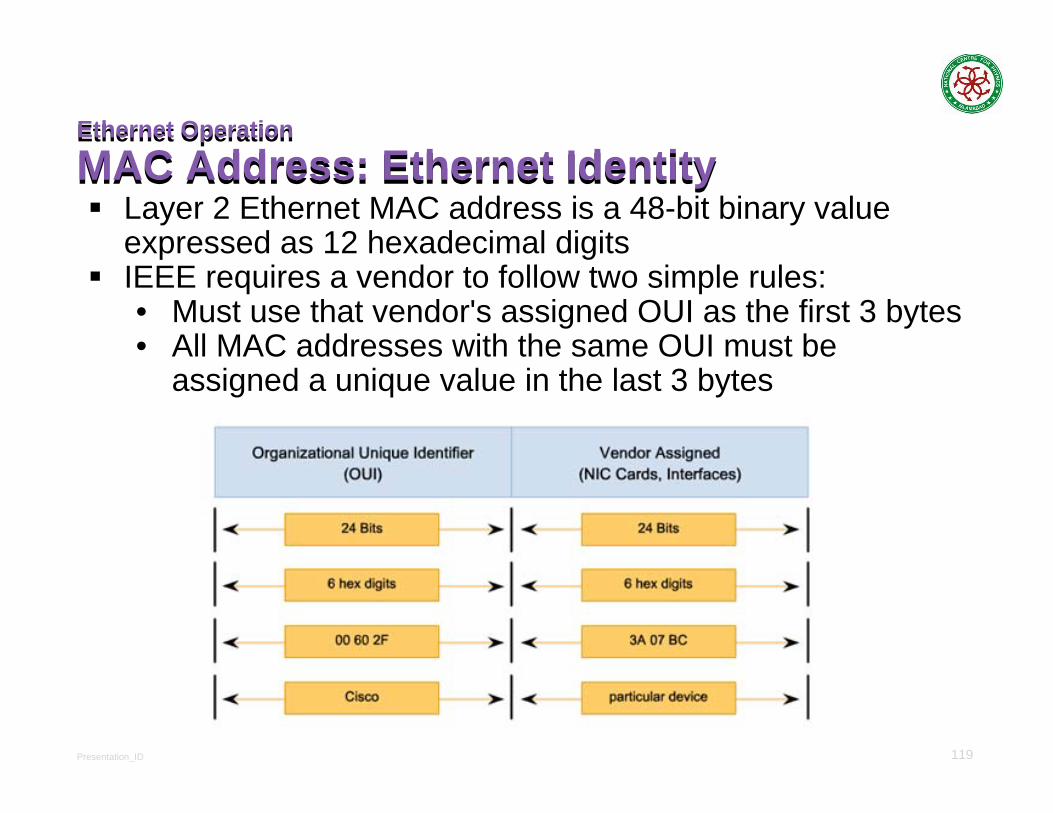
Ethernet Operation
MAC Address: Ethernet IdentityEthernet Operation
MAC Address: Ethernet IdentityLayer 2 Ethernet MAC address is a 48-bit binary value expressed as 12 hexadecimal digitsIEEE requires a vendor to follow two simple rules:• Must use that vendor's assigned OUI as the first 3 bytes• All MAC addresses with the same OUI must be
assigned a unique value in the last 3 bytes

Presentation_ID 120
Ethernet MAC
MAC Addresses and HexadecimalEthernet MAC
MAC Addresses and Hexadecimal
Presentation_ID 121
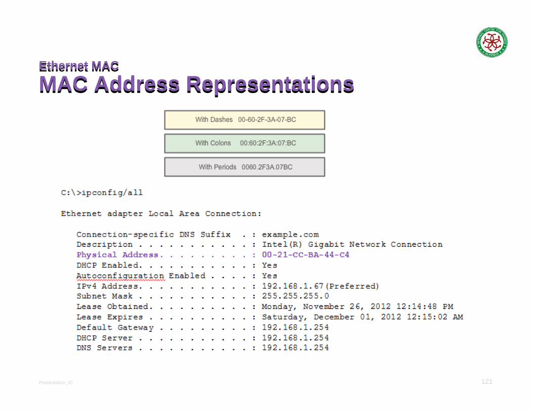
Ethernet MAC
MAC Address RepresentationsEthernet MAC
MAC Address Representations

Presentation_ID 122
Ethernet MAC
Unicast MAC AddressEthernet MAC
Unicast MAC Address

Presentation_ID 123
Ethernet MAC
Broadcast MAC AddressEthernet MAC
Broadcast MAC Address
Presentation_ID 124
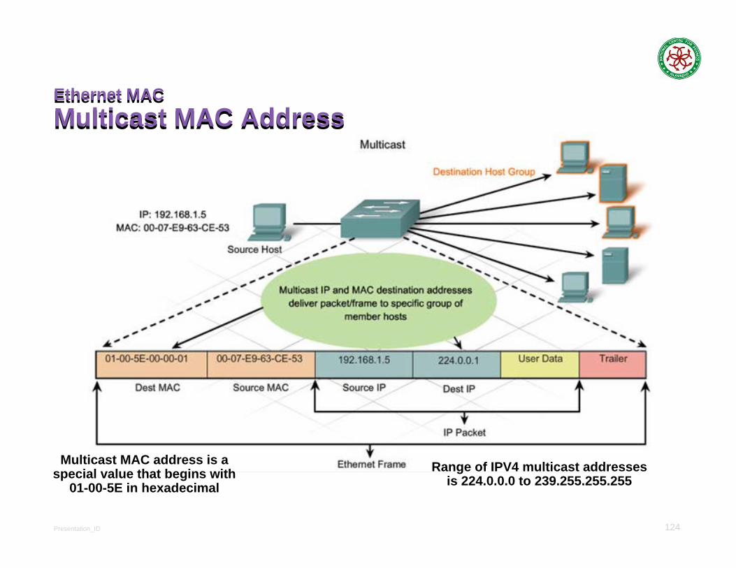
Ethernet MACMulticast MAC AddressEthernet MACMulticast MAC Address
Multicast MAC address is a special value that begins with
01-00-5E in hexadecimalRange of IPV4 multicast addresses
is 224.0.0.0 to 239.255.255.255

Presentation_ID 125
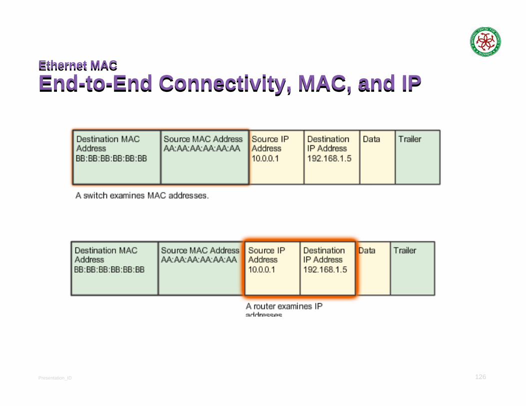
MAC and IPMAC and IPMAC and IPMAC and IPMAC addressThis address does not change Similar to the name of a personKnown as physical address because physically assigned to the host NIC
IP addressSimilar to the address of a person Based on where the host is actually located Known as a logical address because assigned logicallyAssigned to each host by a network administrator
Both the physical MAC and logical IP addresses are required for a computer to communicate just like both the name and address of a person are required to send a letter
Presentation_ID 126
Ethernet MAC
End-to-End Connectivity, MAC, and IPEthernet MAC
End-to-End Connectivity, MAC, and IP

Presentation_ID 127
Network Access
Physical LayerNetwork Access
Physical Layer
Presentation_ID 128
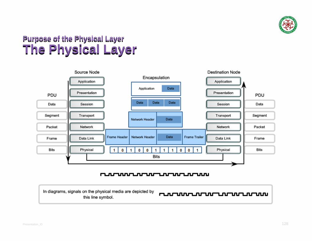
Purpose of the Physical Layer
The Physical LayerPurpose of the Physical Layer
The Physical Layer

Presentation_ID 129
Purpose of the Physical Layer
Physical Layer MediaPurpose of the Physical Layer
Physical Layer Media

Presentation_ID 130
Characteristics of the Physical Layer
BandwidthCharacteristics of the Physical Layer
Bandwidth

Presentation_ID 131
ThroughputThroughputThroughput - The amount of data transferred from one place to another or processed in a specified amount of time.
Throughput= Tranzfer Size/Transfer Time
Transfer Time=RTT+Transfer size/Bandwdith

Presentation_ID 132
Bandwidth vs LatencyBandwidth vs LatencyRelative importance, depends on application
1-byte character:Choice of 1ms vs 100ms dominates 1Mbps vs 100Mbps
25MB file:Choice of 1Mbps vs 100Mbps dominates 1ms vs 100ms
Large data (file transfer) is bandwidth critical
Small data (HTTP) is latency critical
Presentation_ID 133
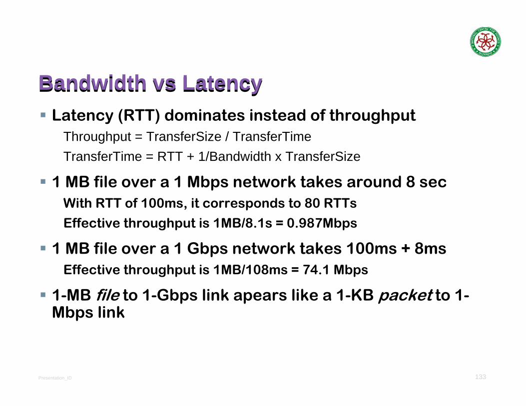
Bandwidth vs LatencyBandwidth vs LatencyLatency (RTT) dominates instead of throughput
Throughput = TransferSize / TransferTimeTransferTime = RTT + 1/Bandwidth x TransferSize
1 MB file over a 1 Mbps network takes around 8 secWith RTT of 100ms, it corresponds to 80 RTTs
Effective throughput is 1MB/8.1s = 0.987Mbps
1 MB file over a 1 Gbps network takes 100ms + 8msEffective throughput is 1MB/108ms = 74.1 Mbps
1-MB file to 1-Gbps link apears like a 1-KB packet to 1-Mbps link

Presentation_ID 134
Characteristics of the Physical Layer
ThroughputCharacteristics of the Physical Layer
Throughput
Presentation_ID 135
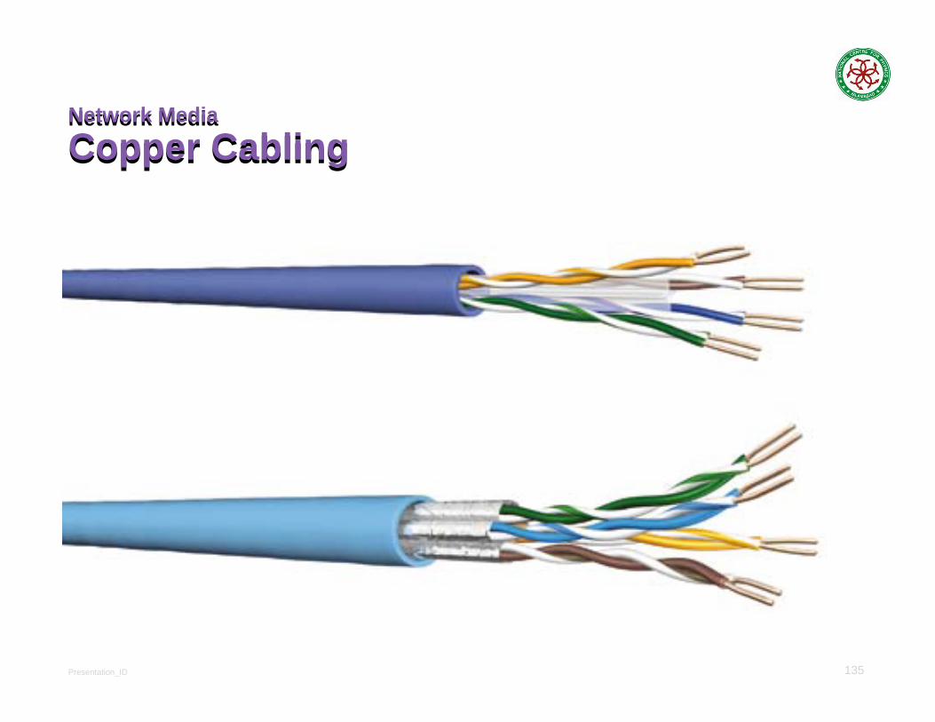
Network Media
Copper CablingNetwork Media
Copper Cabling

Presentation_ID 136
Copper Cabling
Copper MediaCopper Cabling
Copper Media
Shielded Twisted Pair (STP) cableUnshielded Twisted Pair (UTP) cable
Coaxial cable
Presentation_ID 137
Copper Cabling
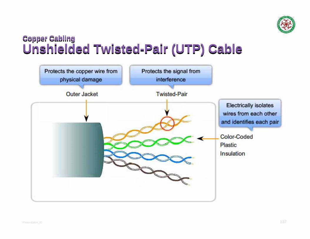
Unshielded Twisted-Pair (UTP) CableCopper Cabling
Unshielded Twisted-Pair (UTP) Cable
Presentation_ID 138
Copper Cabling
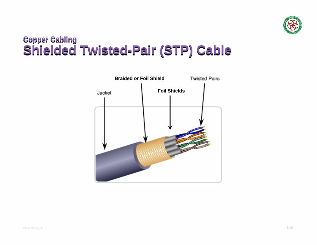
Shielded Twisted-Pair (STP) CableCopper Cabling
Shielded Twisted-Pair (STP) Cable
Foil Shields
Braided or Foil Shield
Presentation_ID 139
Copper Cabling
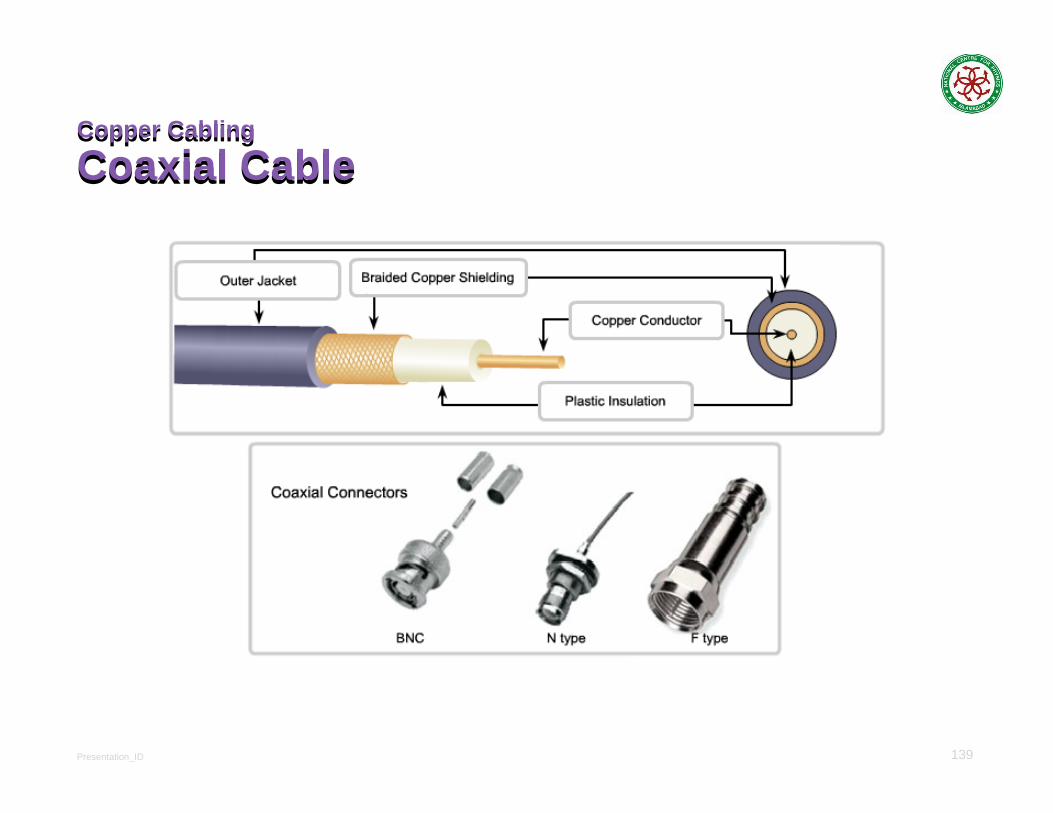
Coaxial CableCopper Cabling
Coaxial Cable

Presentation_ID 140
Copper Cabling
Cooper Media SafetyCopper Cabling
Cooper Media Safety
Presentation_ID 141
UTP Cabling
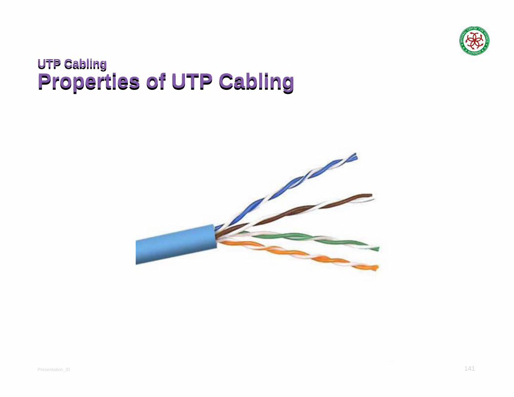
Properties of UTP CablingUTP Cabling
Properties of UTP Cabling

Presentation_ID 142
UTP Cabling
UTP Cabling StandardsUTP Cabling
UTP Cabling Standards
Presentation_ID 143
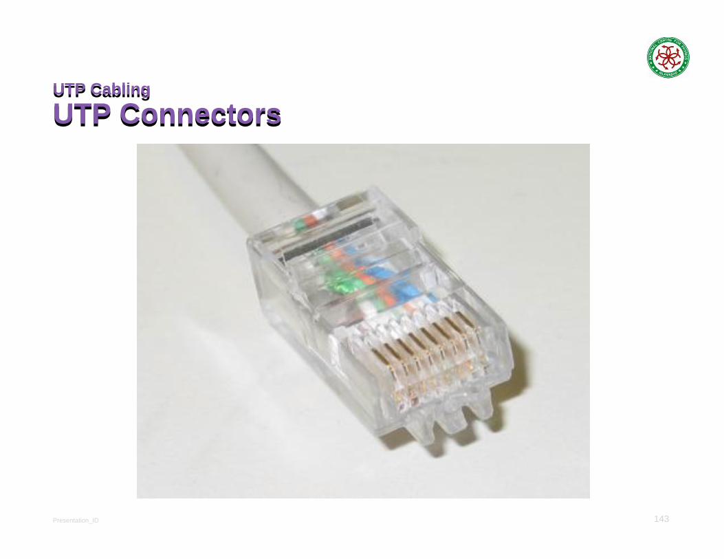
UTP Cabling
UTP ConnectorsUTP Cabling
UTP Connectors

Presentation_ID 144
UTP Cabling
Types of UTP CableUTP Cabling
Types of UTP Cable
Presentation_ID 145
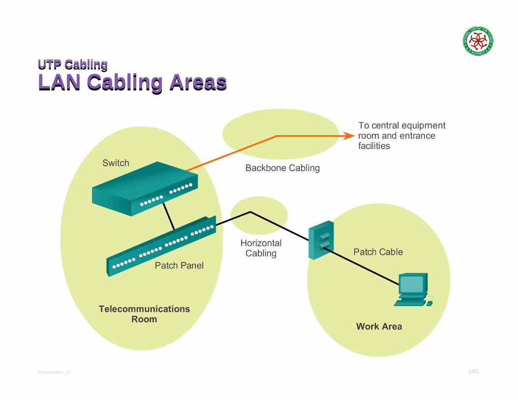
UTP Cabling
LAN Cabling AreasUTP Cabling
LAN Cabling Areas
Presentation_ID 146
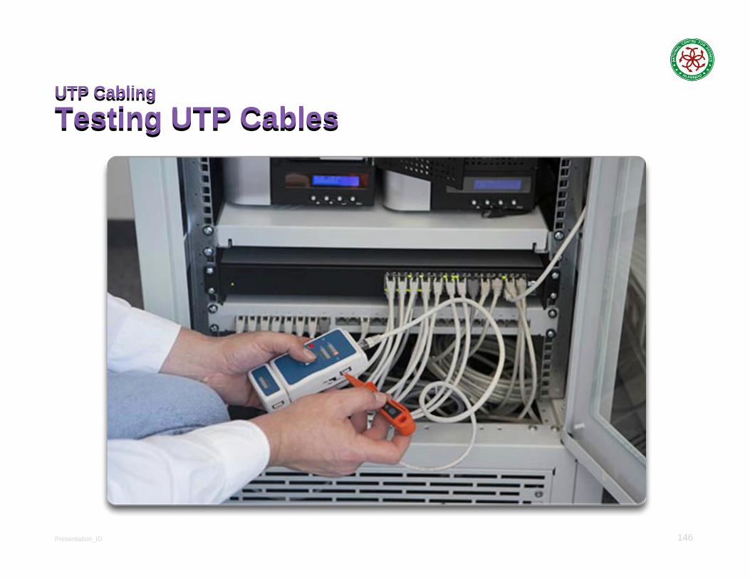
UTP Cabling
Testing UTP CablesUTP Cabling
Testing UTP Cables

Presentation_ID 147
Fiber Optic Cabling
Properties of Fiber Optic CablingFiber Optic Cabling
Properties of Fiber Optic Cabling

Presentation_ID 148
Fiber Optic Cabling
Fiber Media Cable DesignFiber Optic Cabling
Fiber Media Cable Design
Presentation_ID 149
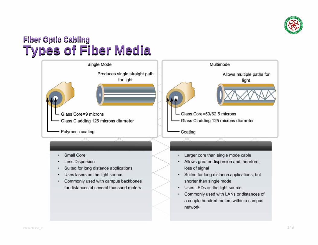
Fiber Optic Cabling
Types of Fiber MediaFiber Optic Cabling
Types of Fiber Media

Presentation_ID 150
Fiber Optic Cabling
Network Fiber ConnectorsFiber Optic Cabling
Network Fiber Connectors

Presentation_ID 151
Fiber Optic Cabling
Fiber versus CopperFiber Optic Cabling
Fiber versus CopperImplementation issues Copper media Fibre-optic
Bandwidth supported 10 Mbps – 10 Gbps 10 Mbps – 100 Gbps
Distance Relatively short(1 – 100 meters)
Relatively High(1 – 100,000 meters)
Immunity to EMI and RFI Low High(Completely immune)
Immunity to electrical hazards Low High(Completely immune)
Media and connector costs Lowest Highest
Installation skills required Lowest Highest
Safety precautions Lowest Highest
Presentation_ID 152
Network Media
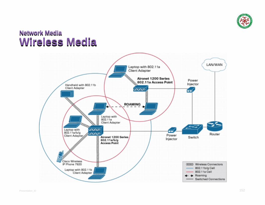
Wireless MediaNetwork Media
Wireless Media

Presentation_ID 153
Wireless Media
Properties of Wireless MediaWireless Media
Properties of Wireless Media

Presentation_ID 154
• IEEE 802.11 standards• Commonly referred to as Wi-Fi.• Uses CSMA/CA• Variations include:
• 802.11a: 54 Mbps, 5 GHz• 802.11b: 11 Mbps, 2.4 GHz• 802.11g: 54 Mbps, 2.4 GHz• 802.11n: 600 Mbps, 2.4 and 5 GHz• 802.11ac: 1 Gbps, 5 GHz• 802.11ad: 7 Gbps, 2.4 GHz, 5 GHz, and 60 GHz
• IEEE 802.15 standard• Supports speeds up to 3 Mbps• Provides device pairing over distances from 1 to
100 meters.
• IEEE 802.16 standard• Provides speeds up to 1 Gbps• Uses a point-to-multipoint topology to provide
wireless broadband access.
Wireless Media
Types of Wireless MediaWireless Media
Types of Wireless Media
Presentation_ID 155
Wireless Media
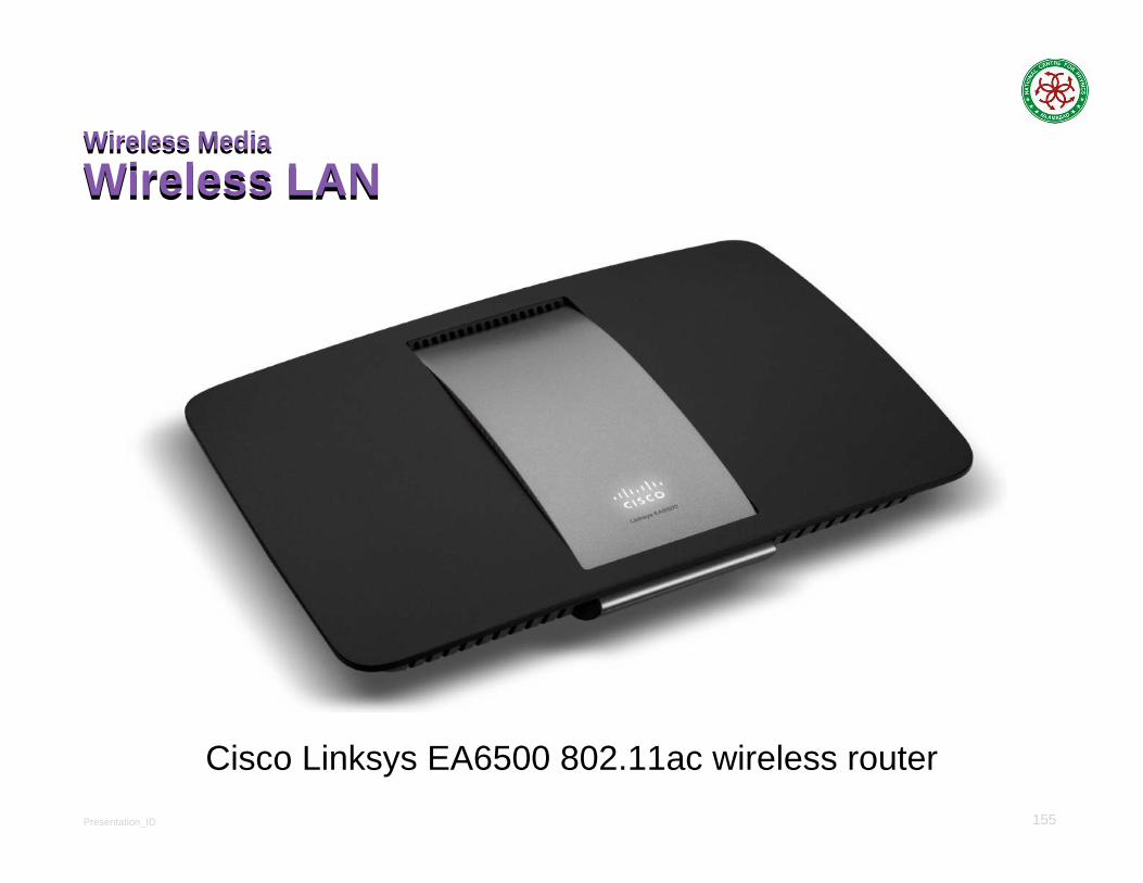
Wireless LANWireless Media
Wireless LAN
Cisco Linksys EA6500 802.11ac wireless router

Presentation_ID 156
Wireless Media
802.11 Wi-Fi StandardsWireless Media
802.11 Wi-Fi Standards
Standard Maximum Speed Frequency Backwards
compatible
802.11a 54 Mbps 5 GHz No
802.11b 11 Mbps 2.4 GHz No
802.11g 54 Mbps 2.4 GHz 802.11b
802.11n 600 Mbps 2.4 GHz or 5 GHz 802.11b/g
802.11ac 1.3 Gbps(1300 Mbps)
2.4 GHz and 5.5 GHz 802.11b/g/n
802.11ad 7 Gbps(7000 Mbps)
2.4 GHz, 5 GHz and 60 GHz 802.11b/g/n/ac