Embed Size (px)
Citation preview
Network Analysis and Synthesis
Chapter 5
Two port networks
1
1. Introduction
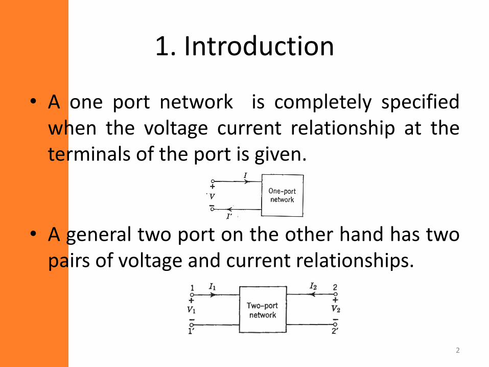
• A one port network is completely specifiedwhen the voltage current relationship at theterminals of the port is given.
• A general two port on the other hand has twopairs of voltage and current relationships.
2
• The variable are V1, V2, I1, I2
• Two of these are independent variables, whilethe rest 2 are dependent variables.
• Hence, there are six possible set of equationsthat describe two port networks.
• There are various ways to write theserelationships
– Z, Y, H and ABCD parameters.
• We will discuss each description.3
2. Z-parameters
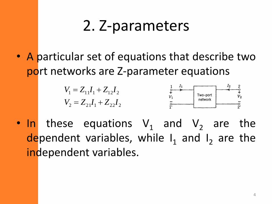
• A particular set of equations that describe twoport networks are Z-parameter equations
• In these equations V1 and V2 are thedependent variables, while I1 and I2 are theindependent variables.
2221212
2121111
IZIZV
IZIZV
4
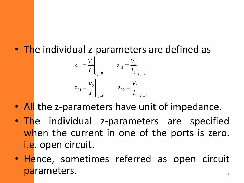
• The individual z-parameters are defined as
• All the z-parameters have unit of impedance.
• The individual z-parameters are specifiedwhen the current in one of the ports is zero.i.e. open circuit.
• Hence, sometimes referred as open circuitparameters.
02
222
01
221
02
112
01
111
12
12
II
II
I
Vz
I
Vz
I
Vz
I
Vz
5
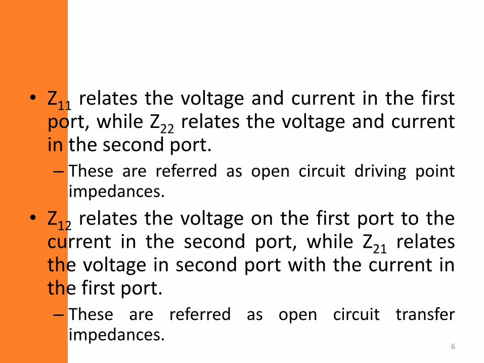
• Z11 relates the voltage and current in the firstport, while Z22 relates the voltage and currentin the second port.– These are referred as open circuit driving point
impedances.
• Z12 relates the voltage on the first port to thecurrent in the second port, while Z21 relatesthe voltage in second port with the current inthe first port.– These are referred as open circuit transfer
impedances.6
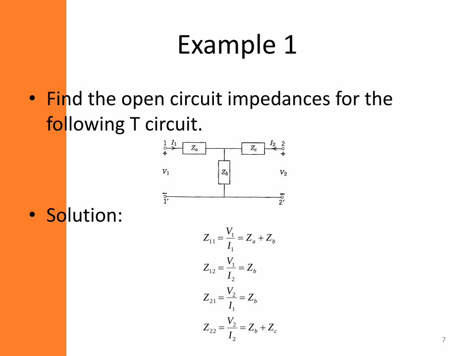
Example 1
• Find the open circuit impedances for the following T circuit.
• Solution:
cb
b
b
ba
ZZI
VZ
ZI
VZ
ZI
VZ
ZZI
VZ
2
222
1
221
2
112
1
111
7
• Note that in the previous example Z12=Z21,hence, the circuit is reciprocal.
• Most passive time-invariant networks arereciprocal.
8
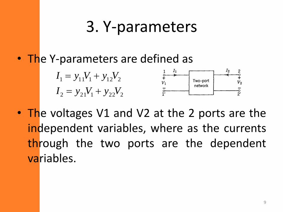
3. Y-parameters
• The Y-parameters are defined as
• The voltages V1 and V2 at the 2 ports are theindependent variables, where as the currentsthrough the two ports are the dependentvariables.
2221212
2121111
VyVyI
VyVyI
9
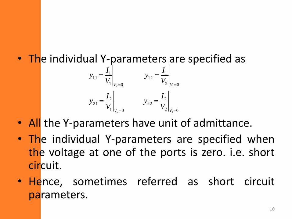
• The individual Y-parameters are specified as
• All the Y-parameters have unit of admittance.
• The individual Y-parameters are specified whenthe voltage at one of the ports is zero. i.e. shortcircuit.
• Hence, sometimes referred as short circuitparameters.
02
222
01
221
02
112
01
111
12
12
VV
VV
V
Iy
V
Iy
V
Iy
V
Iy
10
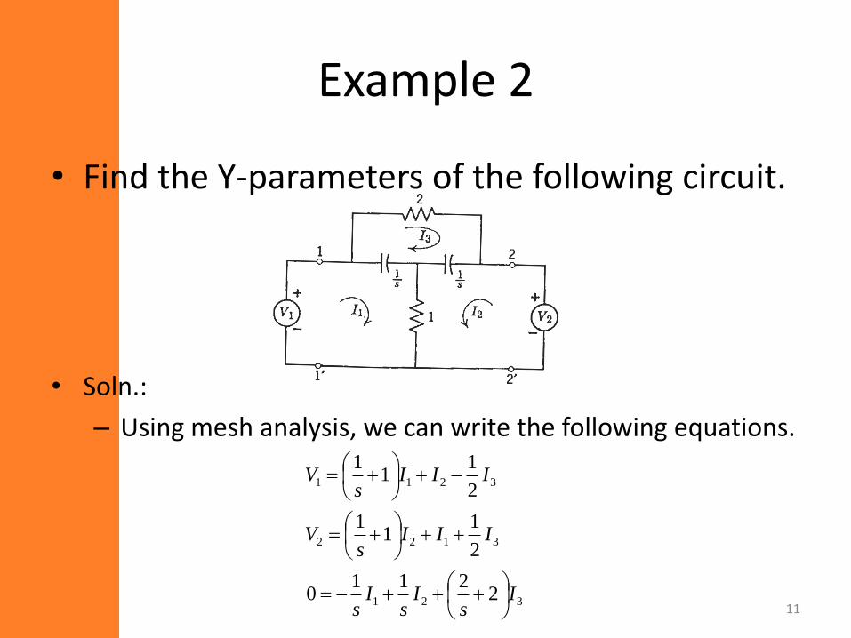
Example 2
• Find the Y-parameters of the following circuit.
• Soln.:
– Using mesh analysis, we can write the following equations.
321
3122
3211
2211
0
2
11
1
2
11
1
Is
Is
Is
IIIs
V
IIIs
V
11
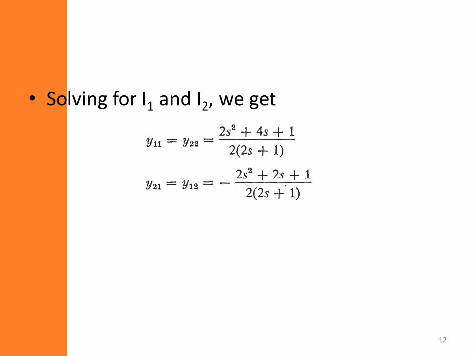
• Solving for I1 and I2, we get
12
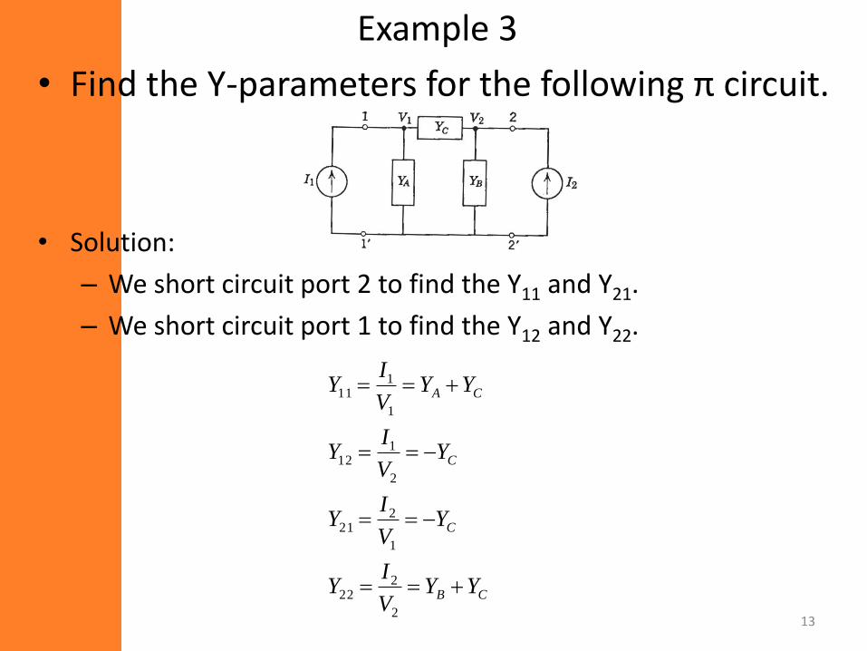
Example 3
• Find the Y-parameters for the following π circuit.
• Solution:
– We short circuit port 2 to find the Y11 and Y21.
– We short circuit port 1 to find the Y12 and Y22.
CB
C
C
CA
YYV
IY
YV
IY
YV
IY
YYV
IY
2
222
1
221
2
112
1
111
13
4. H parameters
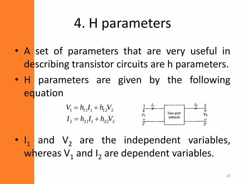
• A set of parameters that are very useful indescribing transistor circuits are h parameters.
• H parameters are given by the followingequation
• I1 and V2 are the independent variables,whereas V1 and I2 are dependent variables.
2221212
2121111
VhIhI
VhIhV
14
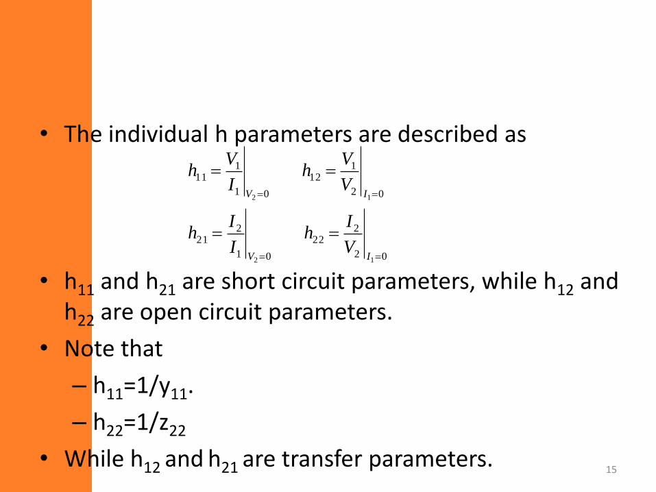
• The individual h parameters are described as
• h11 and h21 are short circuit parameters, while h12 and h22 are open circuit parameters.
• Note that
– h11=1/y11.
– h22=1/z22
• While h12 and h21 are transfer parameters.
02
222
01
221
02
112
01
111
12
12
IV
IV
V
Ih
I
Ih
V
Vh
I
Vh
15
• h parameters are sometimes called hybridparameters since they have both short circuitparameters and open circuit parameters.
16
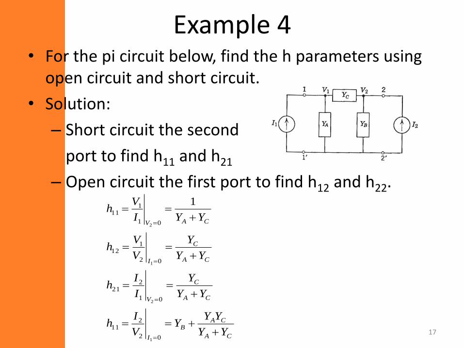
Example 4• For the pi circuit below, find the h parameters using
open circuit and short circuit.
• Solution:
– Short circuit the second
port to find h11 and h21
– Open circuit the first port to find h12 and h22.
CA
CAB
I
CA
C
V
CA
C
I
CAV
YY
YYY
V
Ih
YY
Y
I
Ih
YY
Y
V
Vh
YYI
Vh
02
211
01
221
02
112
01
111
1
2
1
2
1
17
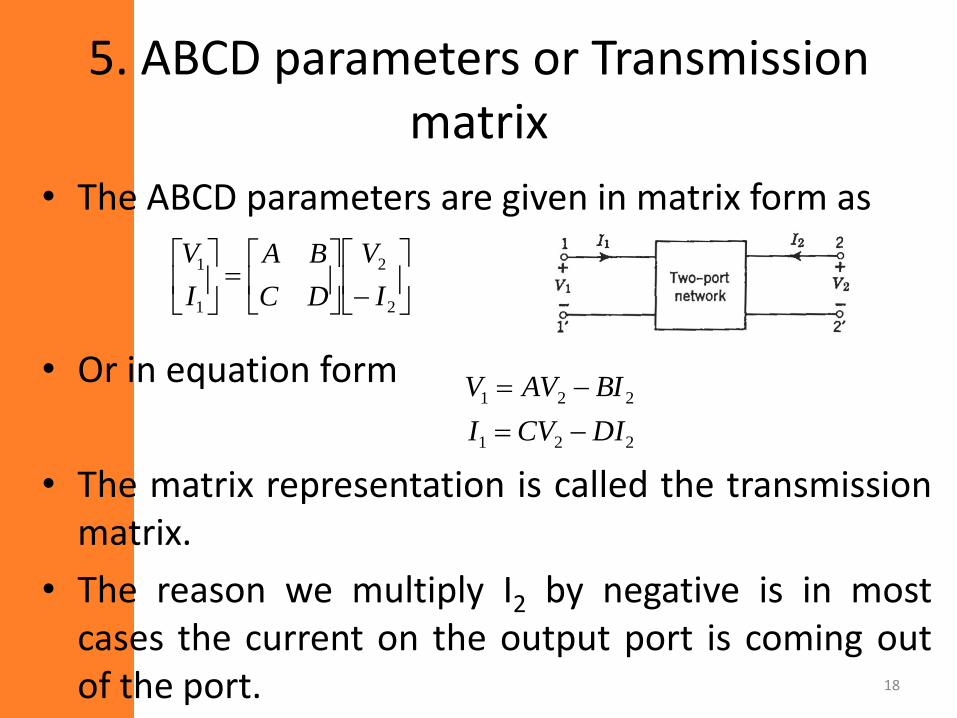
5. ABCD parameters or Transmission matrix
• The ABCD parameters are given in matrix form as
• Or in equation form
• The matrix representation is called the transmissionmatrix.
• The reason we multiply I2 by negative is in mostcases the current on the output port is coming outof the port.
2
2
1
1
I
V
DC
BA
I
V
221
221
DICVI
BIAVV
18
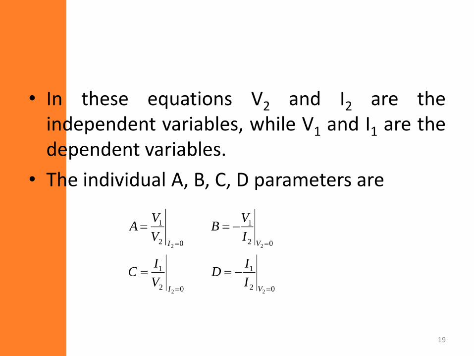
• In these equations V2 and I2 are theindependent variables, while V1 and I1 are thedependent variables.
• The individual A, B, C, D parameters are
02
1
02
1
02
1
02
1
22
22
VI
VI
I
ID
V
IC
I
VB
V
VA
19
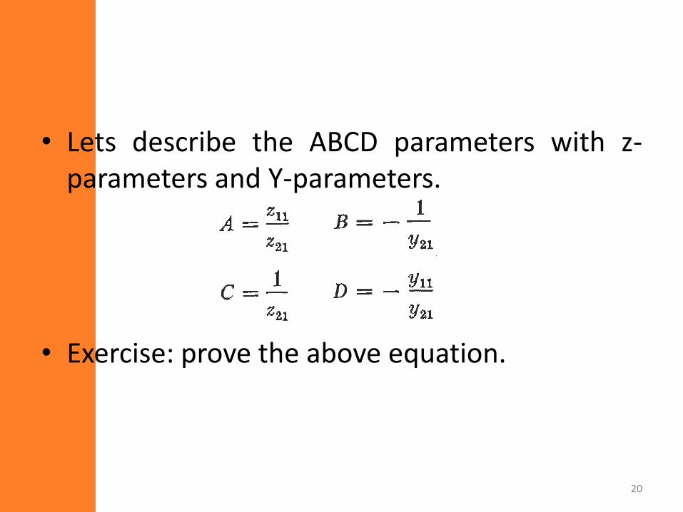
• Lets describe the ABCD parameters with z-parameters and Y-parameters.
• Exercise: prove the above equation.
20
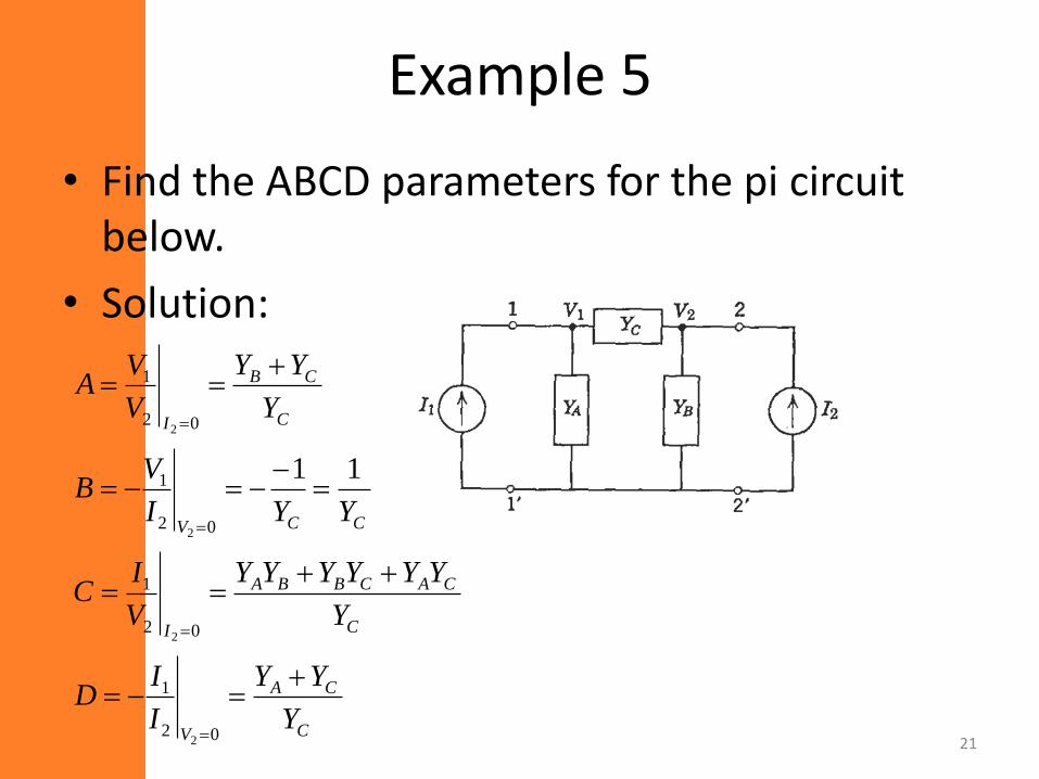
Example 5
• Find the ABCD parameters for the pi circuit below.
• Solution:
C
CA
V
C
CACBBA
I
CCV
C
CB
I
Y
YY
I
ID
Y
YYYYYY
V
IC
YYI
VB
Y
YY
V
VA
02
1
02
1
02
1
02
1
2
2
2
2
11
21
6. Relationship between two port parameters
• Previously we showed that some h parameterscan be given as a function of z and yparameters.
• It turns out that any parameter can beexpressed as a function of any otherparameter.
– This is obvious since all 4 parameters specify agiven 2 port network completely.
22
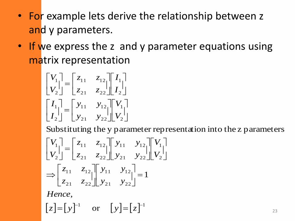
• For example lets derive the relationship between z and y parameters.
• If we express the z and y parameter equations using matrix representation
23 or
,
1
parameters z theintotion representaparameter y thengSubstituti
11
2221
1211
2221
1211
2
1
2221
1211
2221
1211
2
1
2
1
2221
1211
2
1
2
1
2221
1211
2
1
zyyz
Hence
yy
yy
zz
zz
V
V
yy
yy
zz
zz
V
V
V
V
yy
yy
I
I
I
I
zz
zz
V
V
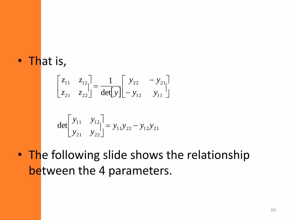
• That is,
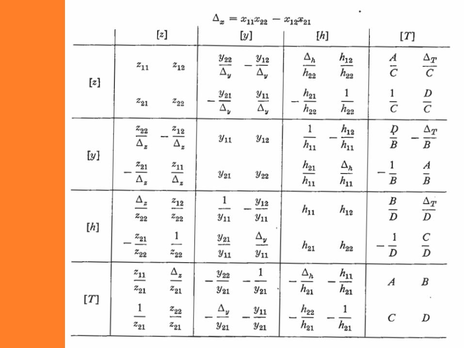
• The following slide shows the relationship between the 4 parameters.
24
21122211
2221
1211
1112
2122
2221
1211
det
det
1
yyyyyy
yy
yy
yy
yzz
zz
25
7. Interconnection of two port networks
• There are three ways 2 two port networks can be connected
– Cascade
– Parallel
– Series
• We will discuss each
26
7.1 Cascade connection
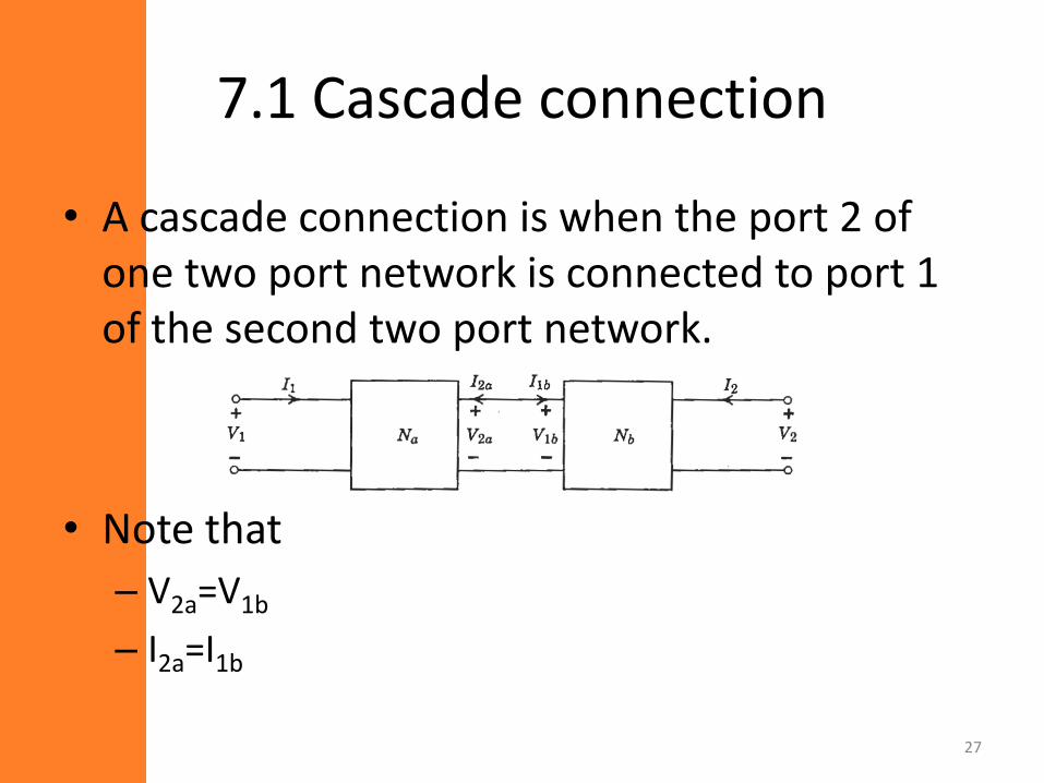
• A cascade connection is when the port 2 of one two port network is connected to port 1 of the second two port network.
• Note that
– V2a=V1b
– I2a=I1b
27
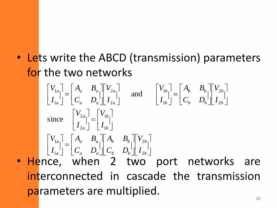
• Lets write the ABCD (transmission) parametersfor the two networks
• Hence, when 2 two port networks areinterconnected in cascade the transmissionparameters are multiplied.
28
b
b
bb
bb
aa
aa
a
a
b
b
a
a
b
b
bb
bb
b
b
a
a
aa
aa
a
a
I
V
DC
BA
DC
BA
I
V
I
V
I
V
I
V
DC
BA
I
V
I
V
DC
BA
I
V
2
2
1
1
1
1
2
2
2
2
1
1
2
2
1
1
since
and
7.2 Parallel
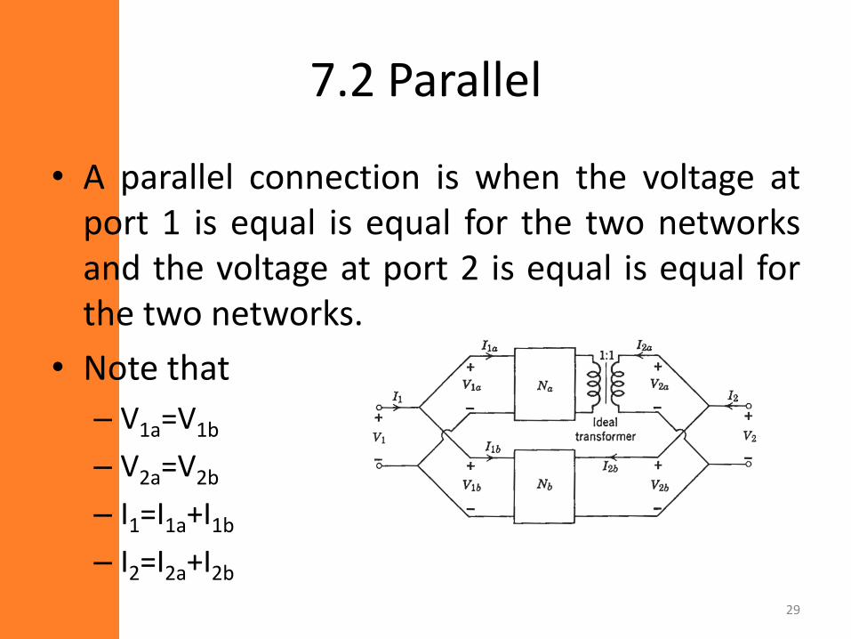
• A parallel connection is when the voltage atport 1 is equal is equal for the two networksand the voltage at port 2 is equal is equal forthe two networks.
• Note that
– V1a=V1b
– V2a=V2b
– I1=I1a+I1b
– I2=I2a+I2b
29
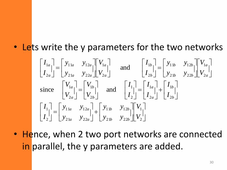
• Lets write the y parameters for the two networks
• Hence, when 2 two port networks are connected in parallel, the y parameters are added.
30
2
1
2221
1211
2221
1211
2
1
2
1
2
1
2
1
2
1
2
1
2
1
2221
1211
2
1
2
1
2221
1211
2
1
and since
and
V
V
yy
yy
yy
yy
I
I
I
I
I
I
I
I
V
V
V
V
V
V
yy
yy
I
I
V
V
yy
yy
I
I
bb
bb
aa
aa
b
b
a
a
b
b
a
a
a
a
bb
bb
b
b
a
a
aa
aa
a
a
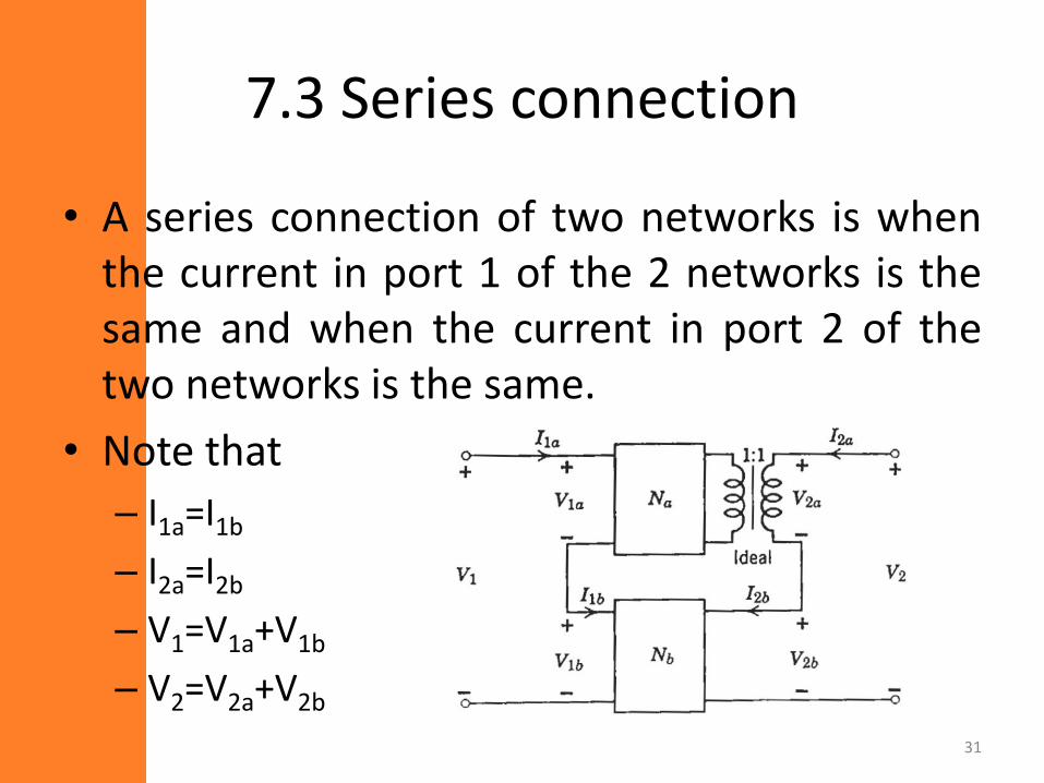
7.3 Series connection
• A series connection of two networks is whenthe current in port 1 of the 2 networks is thesame and when the current in port 2 of thetwo networks is the same.
• Note that
– I1a=I1b
– I2a=I2b
– V1=V1a+V1b
– V2=V2a+V2b
31
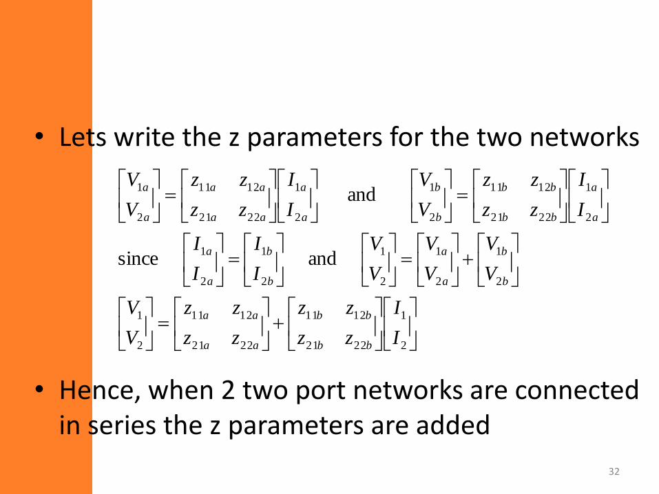
• Lets write the z parameters for the two networks
• Hence, when 2 two port networks are connected in series the z parameters are added
32
2
1
2221
1211
2221
1211
2
1
2
1
2
1
2
1
2
1
2
1
2
1
2221
1211
2
1
2
1
2221
1211
2
1
and since
and
I
I
zz
zz
zz
zz
V
V
V
V
V
V
V
V
I
I
I
I
I
I
zz
zz
V
V
I
I
zz
zz
V
V
bb
bb
aa
aa
b
b
a
a
b
b
a
a
a
a
bb
bb
b
b
a
a
aa
aa
a
a
8. Transfer function using two port parameters
• We have seen how to get transfer function byusing transformed network analysis.
• Here, we will discuss how to obtain transferfunctions using two port parameters.
• There are two broad categories:
– Without load or source impedance and
– With load and/or source impedance.
33
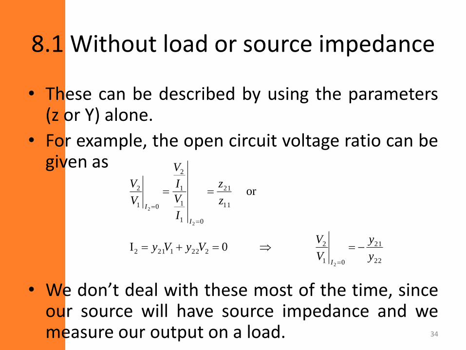
8.1 Without load or source impedance
• These can be described by using the parameters(z or Y) alone.
• For example, the open circuit voltage ratio can begiven as
• We don’t deal with these most of the time, sinceour source will have source impedance and wemeasure our output on a load. 34
22
21
01
22221212
11
21
01
1
1
2
01
2
2
2
2
0I
or
y
y
V
VVyVy
z
z
I
V
I
V
V
V
I
I
I
8.2 With load or source impedance
• These transfer functions are functions of theparameters (z, y, h, t) and the source and/orload impedance.
• To easily find these transfer functions weshould discuss about circuit representations oftwo port parameters.
35
Circuit representations
36
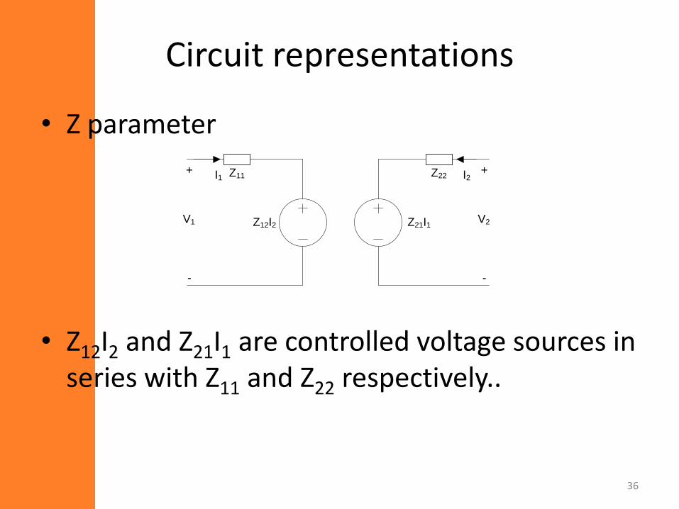
• Z parameter
• Z12I2 and Z21I1 are controlled voltage sources in series with Z11 and Z22 respectively..
Z12I2 Z21I1
Z11 Z22+
-
V1
+
-
V2
I1 I2
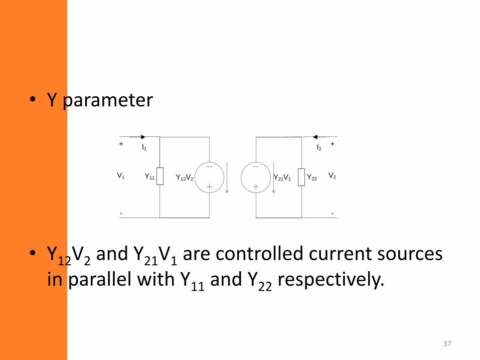
• Y parameter
• Y12V2 and Y21V1 are controlled current sources in parallel with Y11 and Y22 respectively.
37
Y12V2 Y21V1Y11 Y22
+
-
V1
+
-
V2
I1 I2
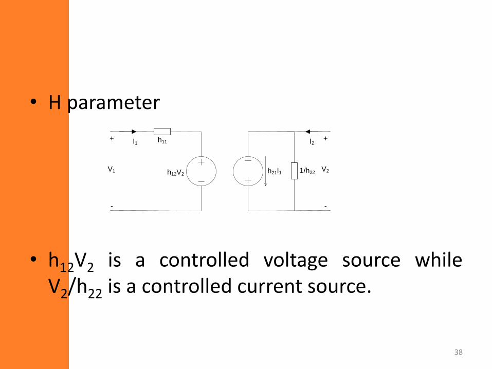
• H parameter
• h12V2 is a controlled voltage source whileV2/h22 is a controlled current source.
38
h12V2h21I1 1/h22
+
-
V1
+
-
V2
I1 I2h11
• The voltage and current sources relating thevarious dependent variables with theindependent variables are called controlledsources. (This is because they are controlledby some variable on the other port).
39
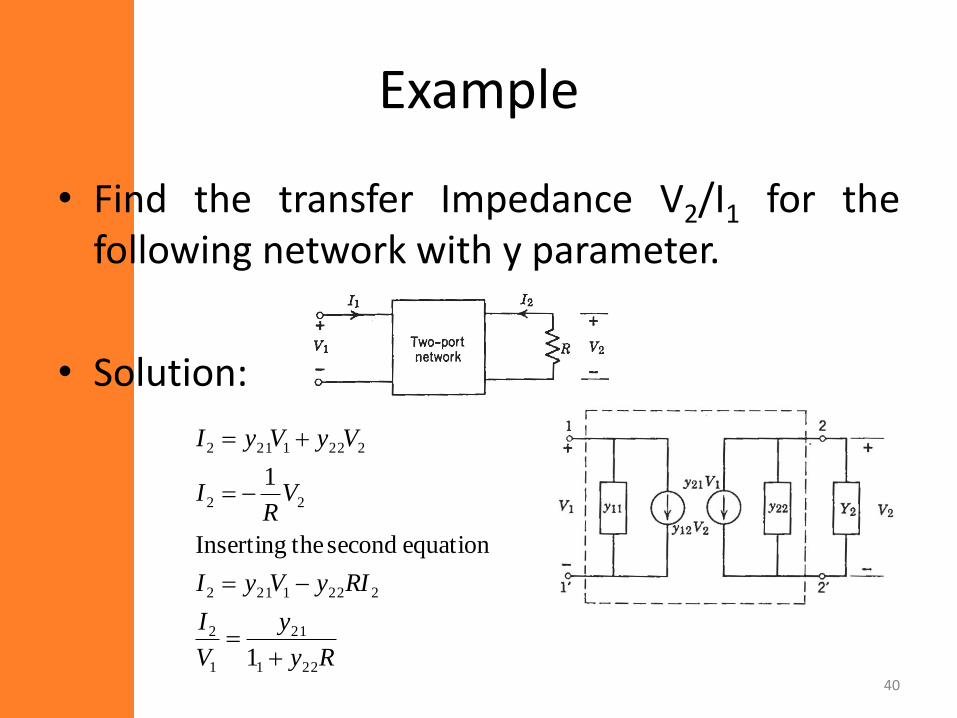
Example
• Find the transfer Impedance V2/I1 for thefollowing network with y parameter.
• Solution:
40
Ry
y
V
I
RIyVyI
VR
I
VyVyI
221
21
1
2
2221212
22
2221212
1
equation second theInserting
1
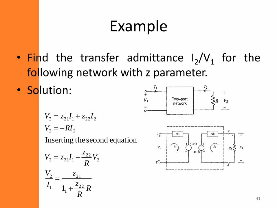
Example
• Find the transfer admittance I2/V1 for thefollowing network with z parameter.
• Solution:
41
RR
z
z
I
V
VR
zIzV
RIV
IzIzV
221
21
1
2
222
1212
22
2221212
1
equation second theInserting
Example
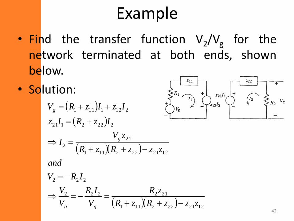
• Find the transfer function V2/Vg for thenetwork terminated at both ends, shownbelow.
• Solution:
42
1221222111
212222
222
1221222111
21
2
2222121
2121111
zzzRzR
zR
V
IR
V
V
IRV
and
zzzRzR
zVI
IzRIz
IzIzRV
gg
g
g
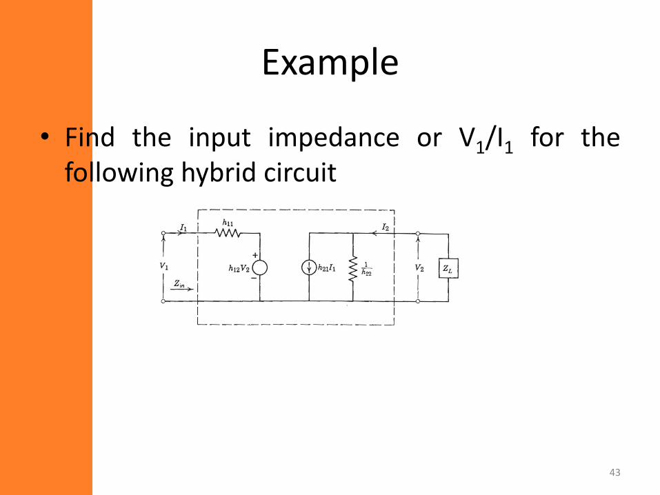
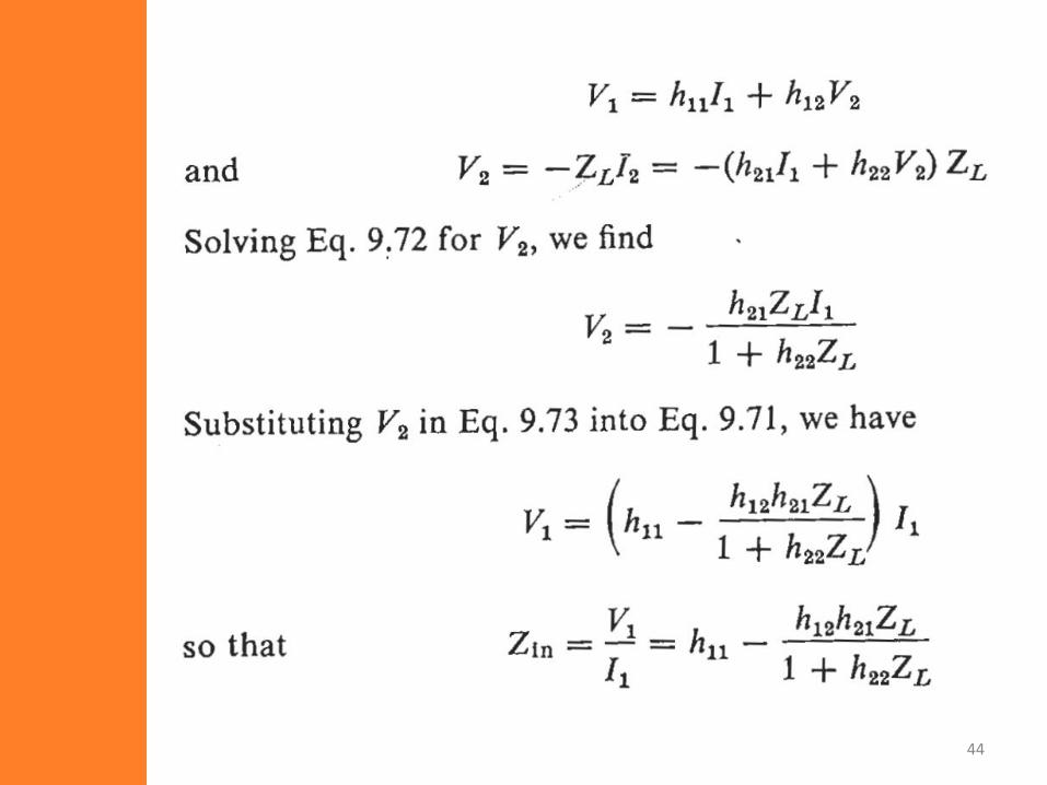
Example
• Find the input impedance or V1/I1 for thefollowing hybrid circuit
43
44