Embed Size (px)
Citation preview
Network Data
Organizational Communications and TechnologiesPrithvi N. Rao
Carnegie Mellon UniversityWeb: http://www.andrew.cmu.edu/course/90-
702/
Reading
Data Communication Fundamentals (Stallings and van Slyke) Chapter 5
TCP/IP and Other Protocol Architectures (Stallings and van
Slyke) Chapter 12
Objectives Be familiar with basic data types
Recognize the difference between analog and digital transmission
Be able to describe how computers handle transmission errors occurring during transmission
Recognize the concept of bandwidth and how it relates to the data transfer capacity of media
Introduction: Review of Analog Signals Amplitude of a wave is measured in decibels
Phase of a wave (0 – 360 degrees) provides information about the position of the wave
Frequency of the wave describes the number of waves present over a given period of time. Measured in cycles per second (hertz).
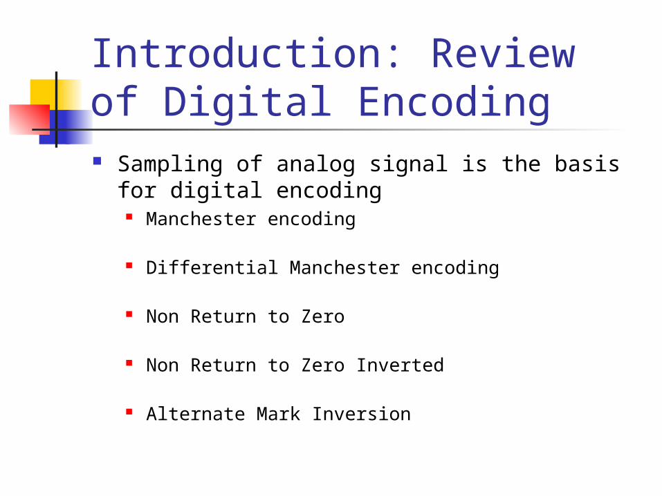
Introduction: Review of Digital Encoding Sampling of analog signal is the basis for
digital encoding Manchester encoding
Differential Manchester encoding
Non Return to Zero
Non Return to Zero Inverted
Alternate Mark Inversion
Digital Versus Analog Digital technology provides benefits over
analog for data transmission
Resilience in terms of immunity to external noise (crosstalk)
Faster and more flexible equipment can be used in digital networks
Most ‘networks’ are digital or are moving in that direction
Asynchronous Character Structure Handshaking permits the transmission of data
in an orderly fashion
Framing data with special control bits indicating the beginning and end of data
Using common timer or clock to determine when the data starts and stops in a transmission
Asynchronous communication uses frames to indicate the beginning and end of each piece of data that is transmitted. Serial communication is an example.
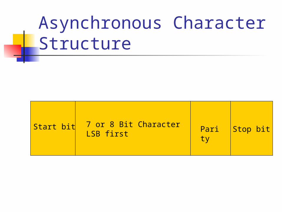
Asynchronous Character Structure
Start bit Parity
Stop bit7 or 8 Bit CharacterLSB first
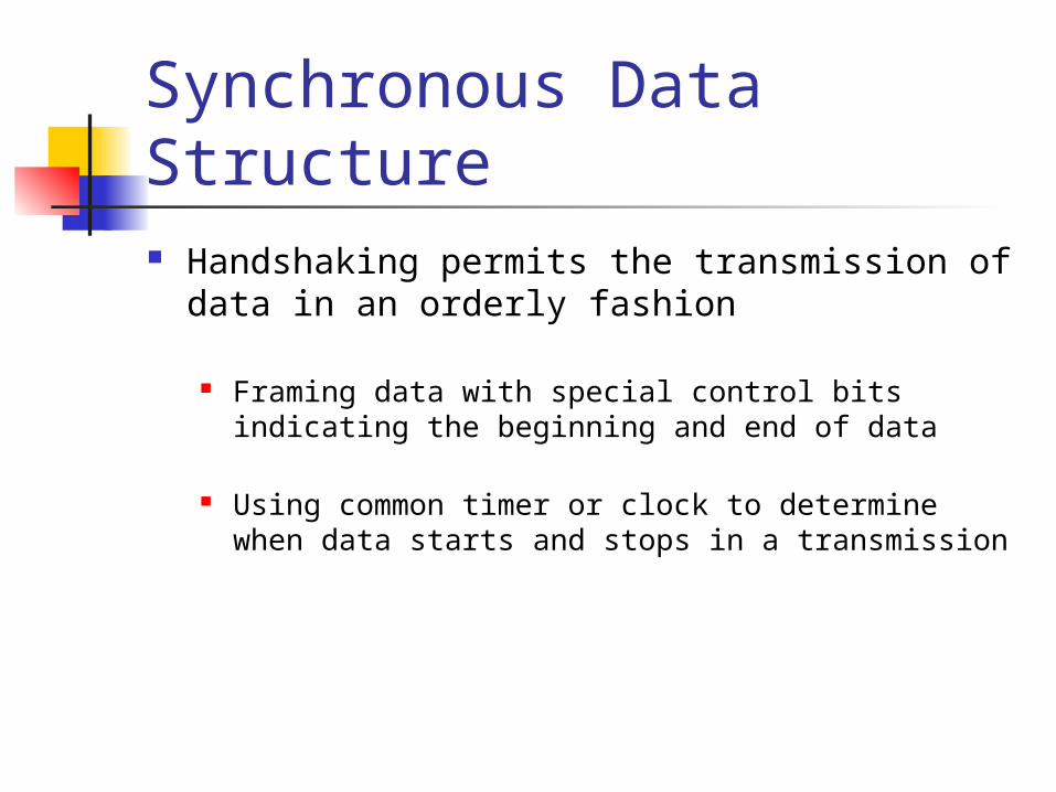
Synchronous Data Structure Handshaking permits the transmission of data
in an orderly fashion
Framing data with special control bits indicating the beginning and end of data
Using common timer or clock to determine when data starts and stops in a transmission
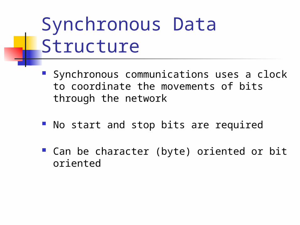
Synchronous Data Structure Synchronous communications uses a clock to
coordinate the movements of bits through the network
No start and stop bits are required
Can be character (byte) oriented or bit oriented
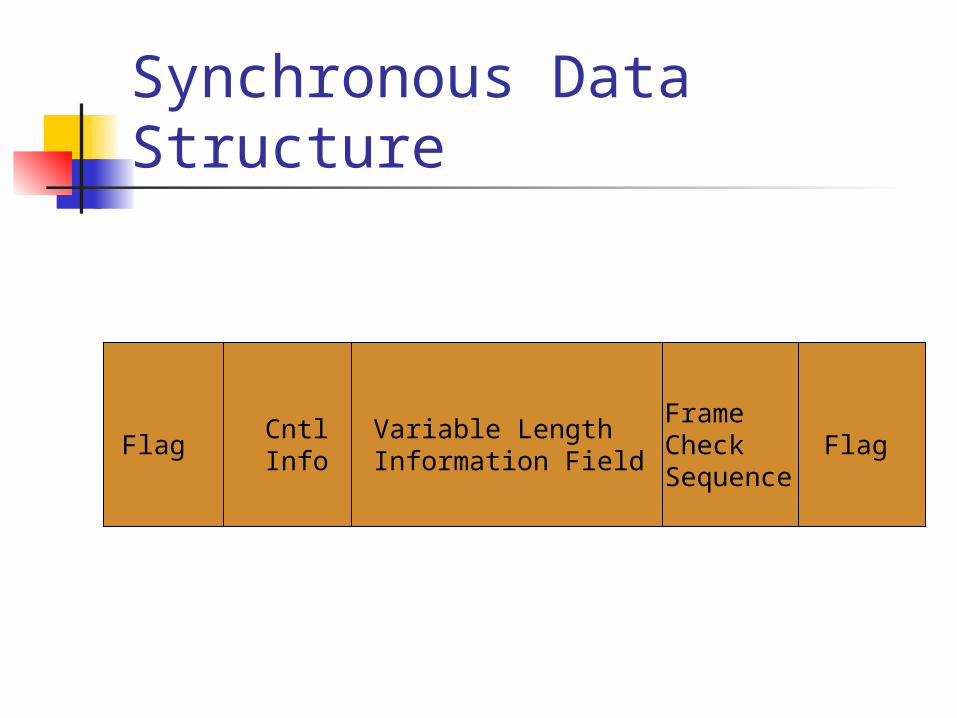
Synchronous Data Structure
FlagCntlInfo
Variable Length Information Field
Frame CheckSequence
Flag
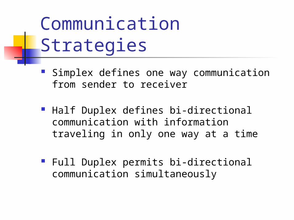
Communication Strategies Simplex defines one way communication from
sender to receiver
Half Duplex defines bi-directional communication with information traveling in only one way at a time
Full Duplex permits bi-directional communication simultaneously
Error Handling Error detection is an important part
consideration of data transmission
Parity checking
Redundancy checking
Parity Checking Involves performing a basic calculation of the
number of digital 0’s and 1’s making up a transmission unit
Parity calculated on even or odd number of 1’s
Parity bit is set per frame (byte or character)
Parity checking is found mostly in Asynchronous communication
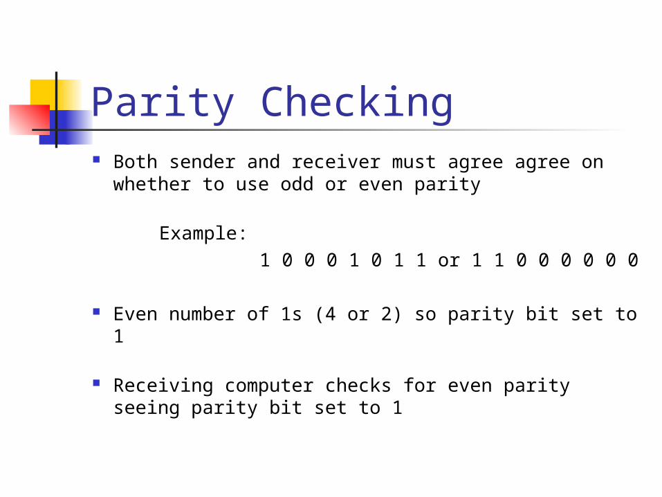
Parity Checking Both sender and receiver must agree agree on
whether to use odd or even parity
Example: 1 0 0 0 1 0 1 1 or 1 1 0 0 0 0 0 0
Even number of 1s (4 or 2) so parity bit set to 1
Receiving computer checks for even parity seeing parity bit set to 1
Cyclic Redundancy Checking Problem with parity checking is that two
different signals could both indicate the same parity
More reliable is CRC or Cyclic Redundancy Check
Check is performed by Totaling entire transmission Divide by a constant prime number Resulting remainder is the CRC validation
CRC Example Consider the following transmission unit
0 0 0 0 1 1 1 1 which adds up to 15 binary Divide this number by 17 (constant prime number)
Remainder is 15 the CRC validation number
Also called Frame or Block checking because it works on the entire transmission not just the start and end
Parity Checking vs CRC CRC can be used with larger units of data
(blocks or frames)
CRC field is made part of the frame;inserted just before the end of the frame delimiter
Parity checking checks one byte at a time
Parity checking can be ambiguous
Error Correction Process of recovery when error is detected
Simple solution is retransmission
Retransmission occurs if receiver does not send and ACK signal
Alternative for retransmission is sending a NACK
Most protocols have some form of acknowledgement
Data Transfer Rates Rate at which signal can move from a 0 to a 1
Speed of encoding process
Amount of overhead involved in framing
Level of error detection
Amount of flow control or handshaking
Flow Control Required to control the speed of communication
Required when receiver cannot accept rate of delivery of data
Limits the speed of transmission
Receiver not ready tells sender to stop transmitting
Window manipulation can reduce amount of data being transmitted
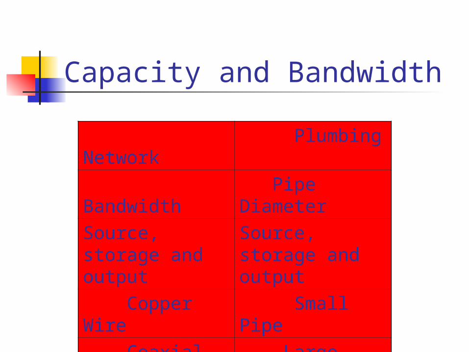
Capacity and Bandwidth
Network Plumbing
Bandwidth Pipe Diameter
Source, storage and output
Source, storage and output
Copper Wire Small Pipe
Coaxial Cable
Large Pipe
Fiber Optic Cable
Larger Pipe
Summary Two basic types of transmission
Analog Digital
Flow control is based on Synchronous transmission relying on a clock Asynchronous transmission indicating start and stop of
data
Parity and CRC are two methods for error checking
Bandwidth is the effective capacity of media


![Prithvi Ghauri Afsanay [Kutubistan.blogspot.com]](https://img.pdfslide.net/doc/110x75/577c781b1a28abe0548ec32d/prithvi-ghauri-afsanay-kutubistanblogspotcom.jpg)