Embed Size (px)
Citation preview
Network Layer – part 3 1
Customer-Provider Routing RelationshipsCustomer-Provider Routing Relationships
The Global Internet consists of Autonomous Systems (AS) interconnected with each other: Customer: Stub AS: small corporation Customer: Multihomed AS: large corporation (no transit) Provider: Transit AS: backbone provider networks
A
B
C
w
x
y
e.g. A, B, C
e.g. x
e.g. w, y
Advertises to its neighbors that it
has no paths to any other destinations
except itself
All traffic entering must be destined for w, all traffic leaving must have originated
from w
Stub AS must be prevented from forwarding traffic between Transit ASs using Selective Route Advertisement Policy
Group of routers
Network Layer – part 3 2
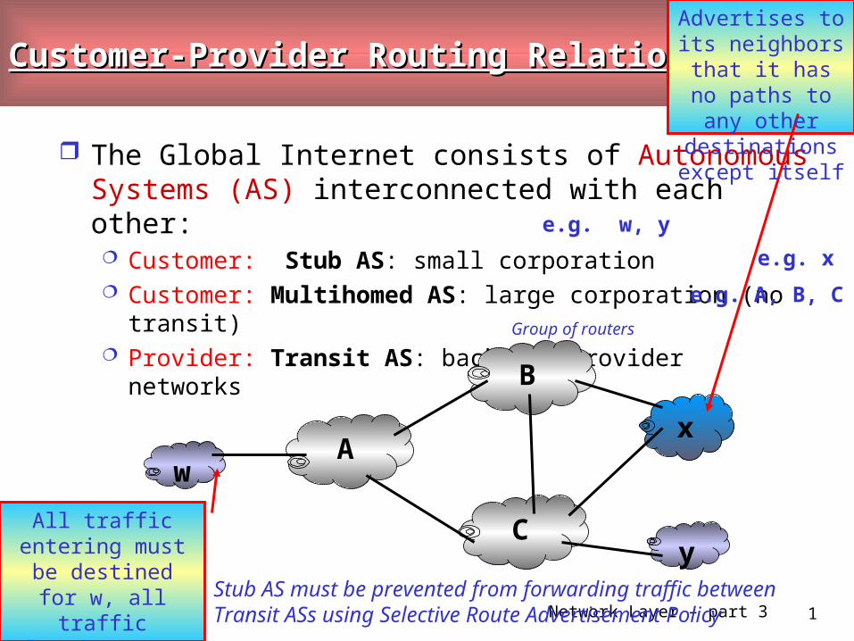
Routing in the Internet
Two-level routing: Intra-AS: administrator is responsible for choice Inter-AS: unique standard
Border Gateway Protocol (BGP4)
de facto standard inter-AS routing protocol in today’s Internet provides each AS a means to:
• obtain subnet reachability information (i.e. via one of its neighboring AS) • propagate the reachability information to all routers internal to the AS• determine “good” routes to subnets based on the reachability information and on AS policy.
Allows each subnet to
advertise its existence to
the rest of the Internet
Network Layer – part 3 3
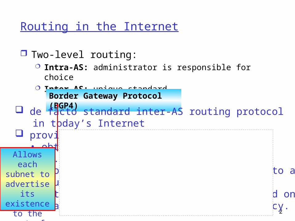
Internet AS HierarchyAS border (exterior gateway) routers
AS interior (gateway) routers
Network Layer – part 3 4
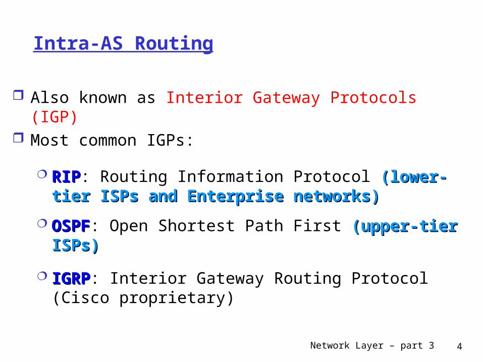
Intra-AS Routing
Also known as Interior Gateway Protocols (IGP) Most common IGPs:
RIPRIP: Routing Information Protocol (lower-tier ISPs and (lower-tier ISPs and Enterprise networks)Enterprise networks)
OSPFOSPF: Open Shortest Path First (upper-tier ISPs)(upper-tier ISPs)
IGRPIGRP: Interior Gateway Routing Protocol (Cisco proprietary)
Network Layer – part 3 5
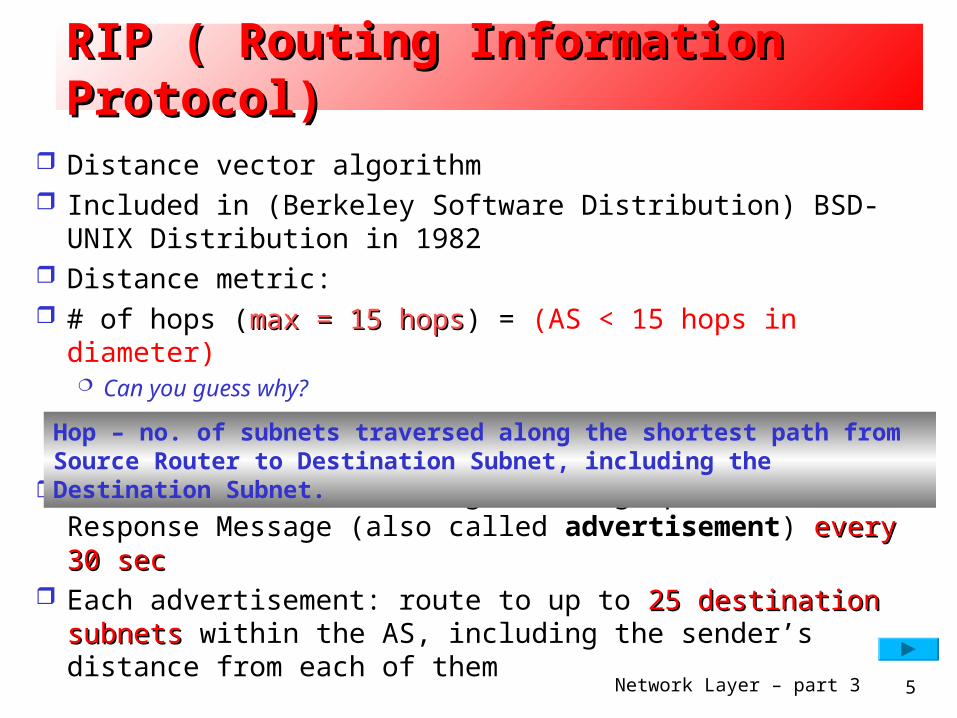
RIP ( Routing Information Protocol)RIP ( Routing Information Protocol)
Distance vector algorithm Included in (Berkeley Software Distribution) BSD-UNIX
Distribution in 1982 Distance metric: # of hops (max = 15 hopsmax = 15 hops) = (AS < 15 hops in diameter)
Can you guess why?
Distance vectors: exchange routing updates via Response Message (also called advertisement) every 30 secevery 30 sec
Each advertisement: route to up to 25 destination subnets25 destination subnets within the AS, including the sender’s distance from each of them
Hop – no. of subnets traversed along the shortest path from Source Router to Destination Subnet, including the Destination Subnet.
Network Layer – part 3 6
RIP (Routing Information Protocol) RIP (Routing Information Protocol)
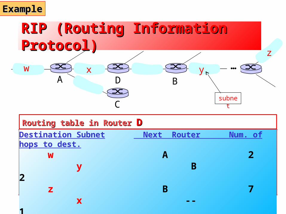
Destination Subnet Next Router Num. of hops to dest. w A 2
y B 2 z B 7
x -- 1... ... ....
w x y
z
A
C
D B
Routing table in Router Routing table in Router DD
…
ExampleExample
subnet
Network Layer – part 3 7
RIP (Routing Information Protocol) RIP (Routing Information Protocol)
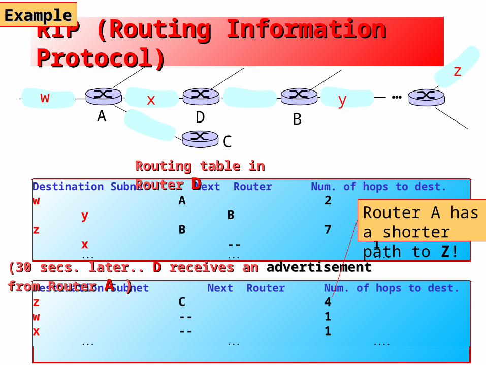
Destination Subnet Next Router Num. of hops to dest.w A 2
y B 2z B 7
x -- 1... ... ....
w x y
z
A
C
D B
Routing table in Router Routing table in Router DD
…
ExampleExample
Destination Subnet Next Router Num. of hops to dest.z C 4w -- 1x -- 1
... ... ....
(30 secs. later.. (30 secs. later.. DD receives an receives an advertisementadvertisement from Router from Router AA ) )
Router A has a shorter path to Z!
Network Layer – part 3 8
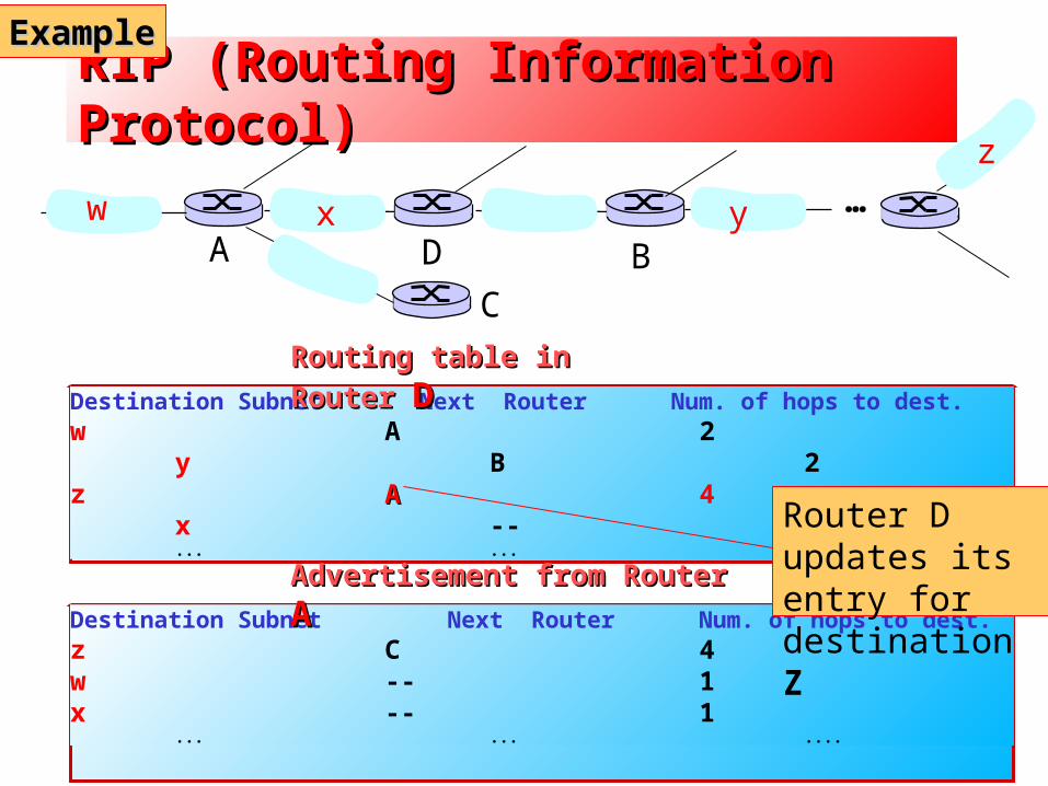
RIP (Routing Information Protocol) RIP (Routing Information Protocol)
Destination Subnet Next Router Num. of hops to dest.w A 2
y B 2z AA 4
x -- 1... ... ....
w x y
z
A
C
D B
Routing table in Router Routing table in Router DD
…
ExampleExample
Destination Subnet Next Router Num. of hops to dest.z C 4w -- 1x -- 1
... ... ....
Advertisement from Router Advertisement from Router AA
Router D updates its entry for destination Z
Network Layer – part 3 9
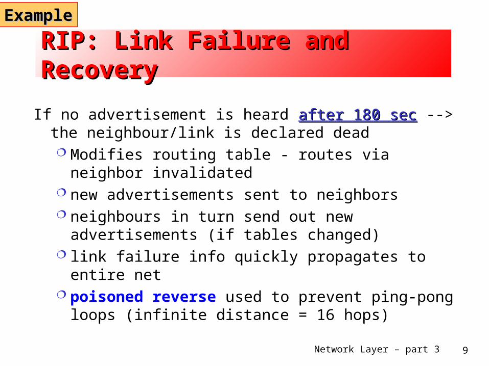
RIP: Link Failure and Recovery RIP: Link Failure and Recovery
If no advertisement is heard after 180 secafter 180 sec --> the neighbour/link is declared dead Modifies routing table - routes via neighbor invalidated new advertisements sent to neighbors neighbours in turn send out new advertisements (if
tables changed) link failure info quickly propagates to entire net poisoned reverse used to prevent ping-pong loops
(infinite distance = 16 hops)
ExampleExample
Network Layer – part 3 10
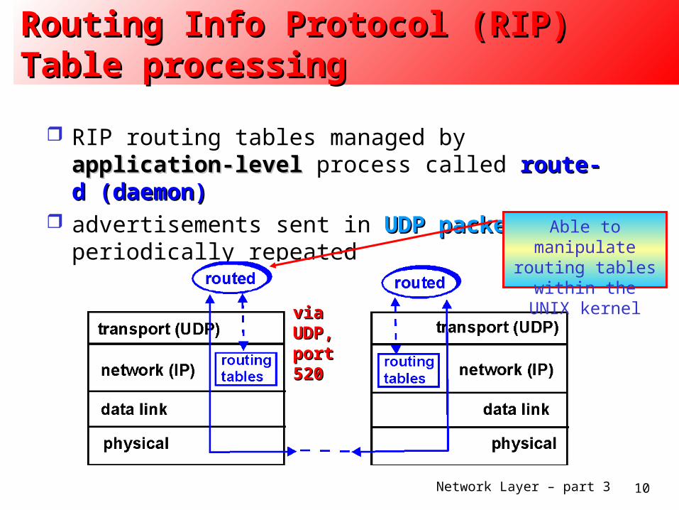
Routing Info Protocol (RIP) Routing Info Protocol (RIP) Table processingTable processing
RIP routing tables managed by application-level application-level process called route-d (daemon)route-d (daemon)
advertisements sent in UDP packetsUDP packets, periodically repeated Able to manipulate
routing tables within the UNIX kernel
via UDP, via UDP, port 520port 520
Network Layer – part 3 11
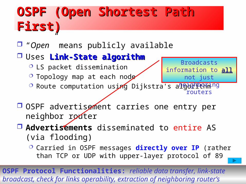
OSPF (Open Shortest Path First)OSPF (Open Shortest Path First)
“Open” means publicly available Uses Link-State algorithm Link-State algorithm
LS packet dissemination Topology map at each node Route computation using Dijkstra's algorithm
OSPF advertisement carries one entry per neighbor router
Advertisements disseminated to entire AS (via flooding) Carried in OSPF messages directly over IP (rather than TCP or
UDP with upper-layer protocol of 89
Broadcasts information to all all not just neighboring
routers
OSPF Protocol Functionalities: reliable data transfer, link-state broadcast, check for links operability, extraction of neighboring router’s database of network-wide link state
Network Layer – part 3 12
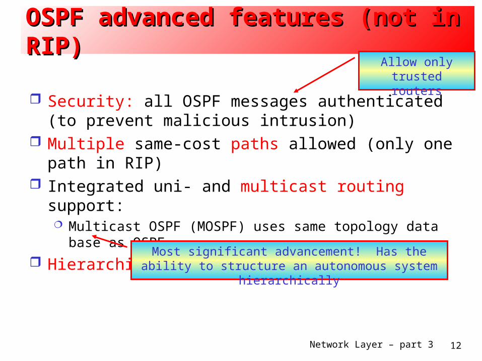
OSPF advanced features (not in RIP)OSPF advanced features (not in RIP)
Security: all OSPF messages authenticated (to prevent malicious intrusion)
Multiple same-cost paths allowed (only one path in RIP) Integrated uni- and multicast routing support:
Multicast OSPF (MOSPF) uses same topology data base as OSPF
Hierarchical OSPF in large domains.
Allow only trusted routers
Most significant advancement! Has the ability to structure an autonomous system hierarchically
Network Layer – part 3 13
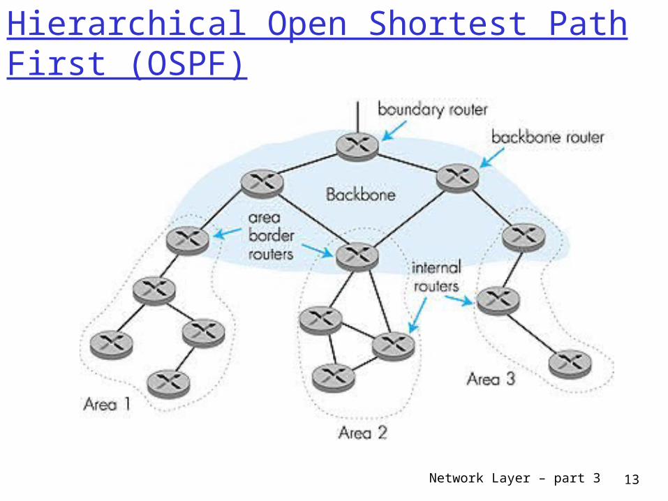
Hierarchical Open Shortest Path First (OSPF)
Network Layer – part 3 14
Hierarchical OSPFHierarchical OSPF
Two-level hierarchy: local area, backbone. Link-state advertisements are sent only within an area each node has detailed area topology; only know
direction (shortest path) to nets in other areas. Each area runs its own OSPF link-state routing algorithm
Area border routers: responsible for routing packets outside the area.
Backbone routers: run OSPF routing limited to backbone.
Boundary routers: connect to other ASs.
Network Layer – part 3 15
IGRP (Interior Gateway Routing Protocol) CISCO proprietary; successor of RIP (mid 80s) Uses the Distance Vector algorithm, like RIP several cost metrics (delay, bandwidth,
reliability, load, etc.) uses TCP to exchange routing updates Loop-free routing via Distributed Updating Alg.
(DUAL) based on diffused computation
Network Layer – part 3 16
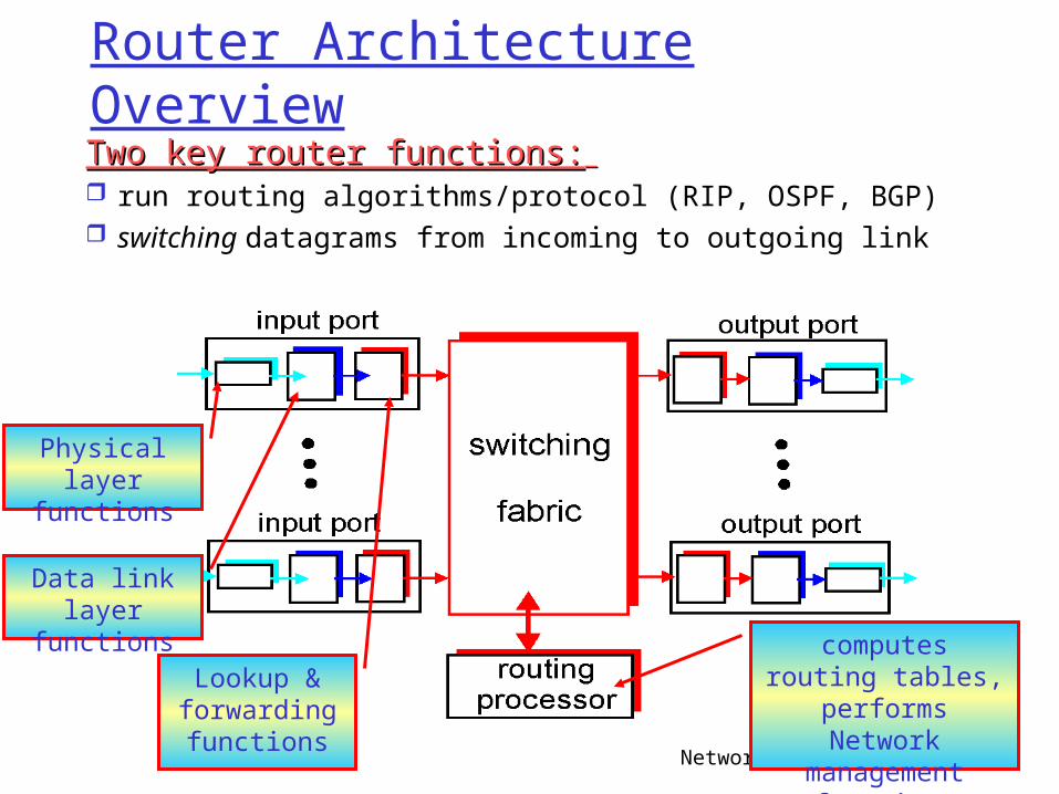
Router Architecture Overview
Two key router functions:Two key router functions:
run routing algorithms/protocol (RIP, OSPF, BGP) switching datagrams from incoming to outgoing link
Physical layer functions
Data link layer functions
Lookup & forwarding functions
computes routing tables, performs
Network management functions
Network Layer – part 3 17
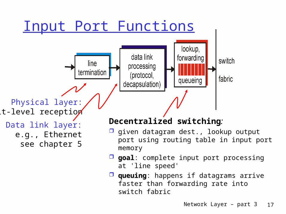
Input Port Functions
Decentralized switching: given datagram dest., lookup output port
using routing table in input port memory goalgoal: complete input port processing at
'line speed' queuingqueuing: happens if datagrams arrive
faster than forwarding rate into switch fabric
Physical layer:bit-level reception
Data link layer:e.g., Ethernetsee chapter 5
Network Layer – part 3 18
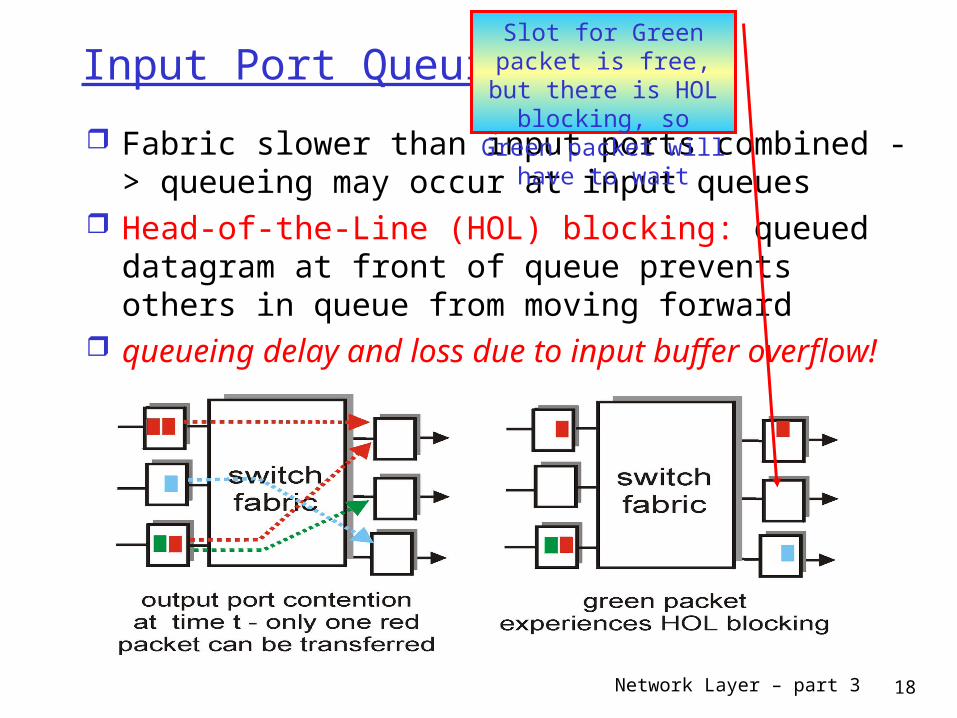
Input Port Queuing
Fabric slower than input ports combined -> queueing may occur at input queues
Head-of-the-Line (HOL) blocking: queued datagram at front of queue prevents others in queue from moving forward
queueing delay and loss due to input buffer overflow!
Slot for Green packet is free, but there is HOL
blocking, so Green packet will have to wait
Network Layer – part 3 19
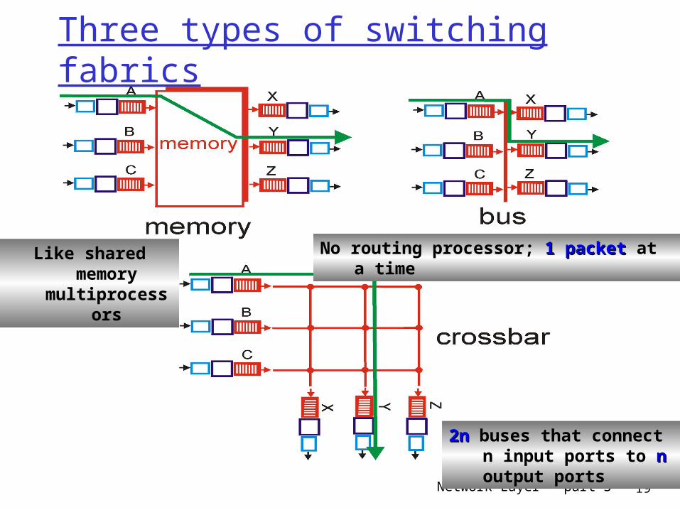
Three types of switching fabrics
No routing processor; 1 packet 1 packet at a timeLike shared memory multiprocessors
2n2n buses that connect n input ports to nn output ports
Network Layer – part 3 20
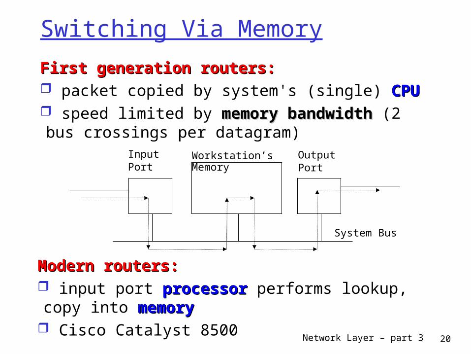
Switching Via Memory
First generation routers:First generation routers: packet copied by system's (single) CPUCPU speed limited by memory bandwidth memory bandwidth (2 bus crossings per datagram)
InputPort
OutputPort
Workstation’sMemory
System Bus
Modern routers:Modern routers: input port processorprocessor performs lookup, copy into memorymemory
Cisco Catalyst 8500
Network Layer – part 3 21
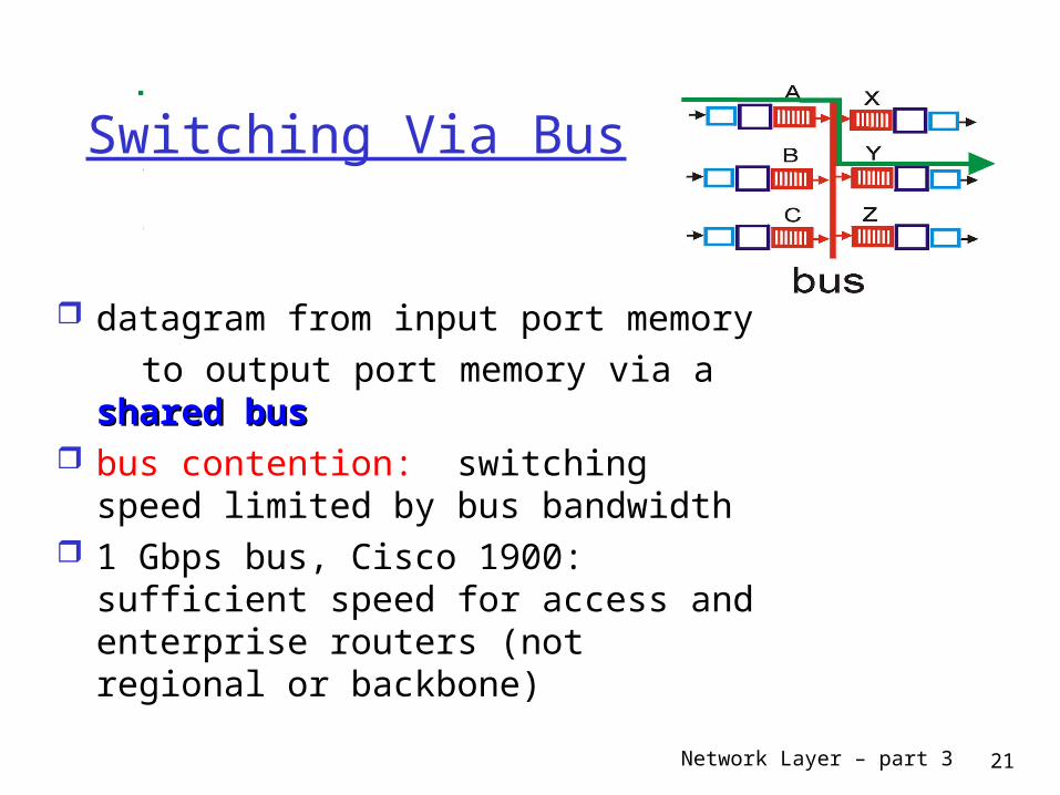
Switching Via Bus
datagram from input port memory to output port memory via a shared shared
busbus bus contention: switching speed
limited by bus bandwidth 1 Gbps bus, Cisco 1900: sufficient
speed for access and enterprise routers (not regional or backbone)
Network Layer – part 3 22
Switching Via An Interconnection Network
overcome bus bandwidth limitations Banyan networks, other interconnection nets
initially developed to connect processors in multiprocessor
Other Advanced design: fragmenting fragmenting datagram datagram into fixed length cells, switch cells through the fabric.
Cisco 12000: switches 60 Gbps through the interconnection network
Network Layer – part 3 23
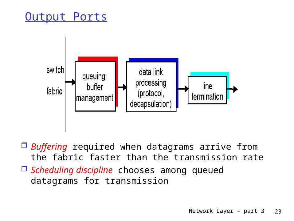
Output Ports
Buffering required when datagrams arrive from the fabric faster than the transmission rate
Scheduling discipline chooses among queued datagrams for transmission
Network Layer – part 3 24
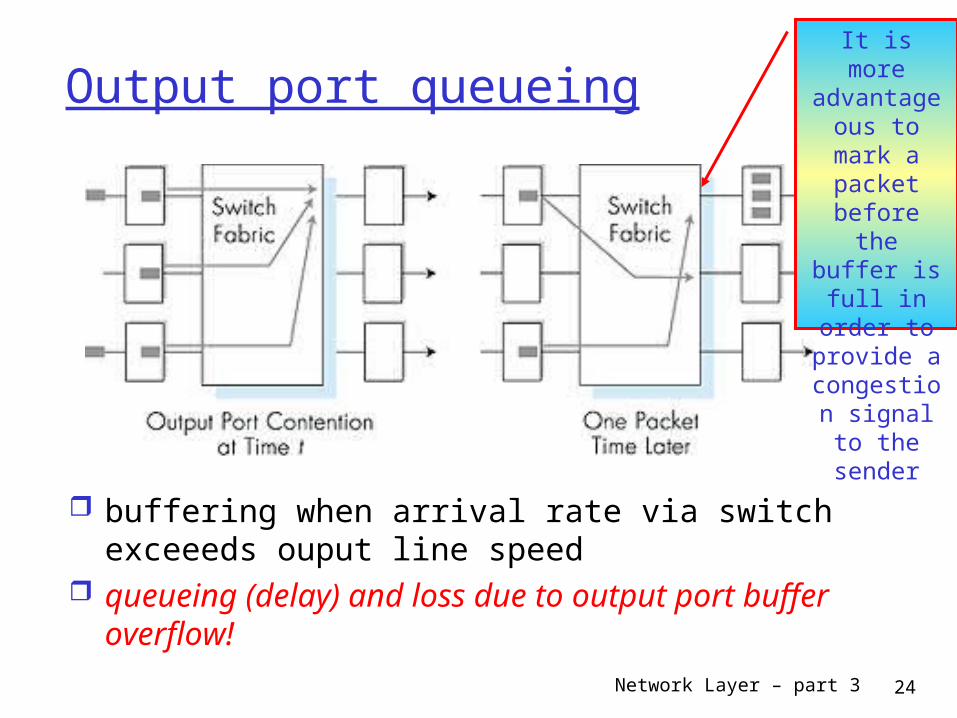
Output port queueing
buffering when arrival rate via switch exceeeds ouput line speed
queueing (delay) and loss due to output port buffer overflow!
It is more advantageous
to mark a packet before the buffer is
full in order to provide a
congestion signal to the
sender

Network Layer – part 3 25
END OF SESSION
Network Layer – part 3 26
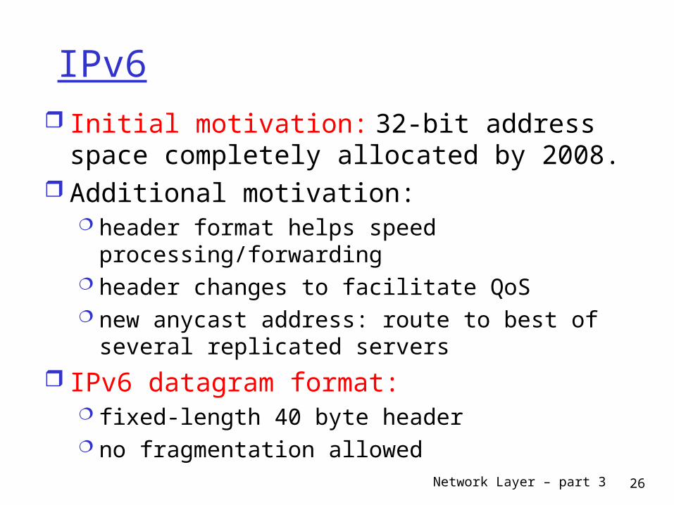
IPv6 Initial motivation: 32-bit address space
completely allocated by 2008. Additional motivation:
header format helps speed processing/forwarding
header changes to facilitate QoS new anycast address: route to best of several
replicated servers IPv6 datagram format:
fixed-length 40 byte header no fragmentation allowed
Network Layer – part 3 27
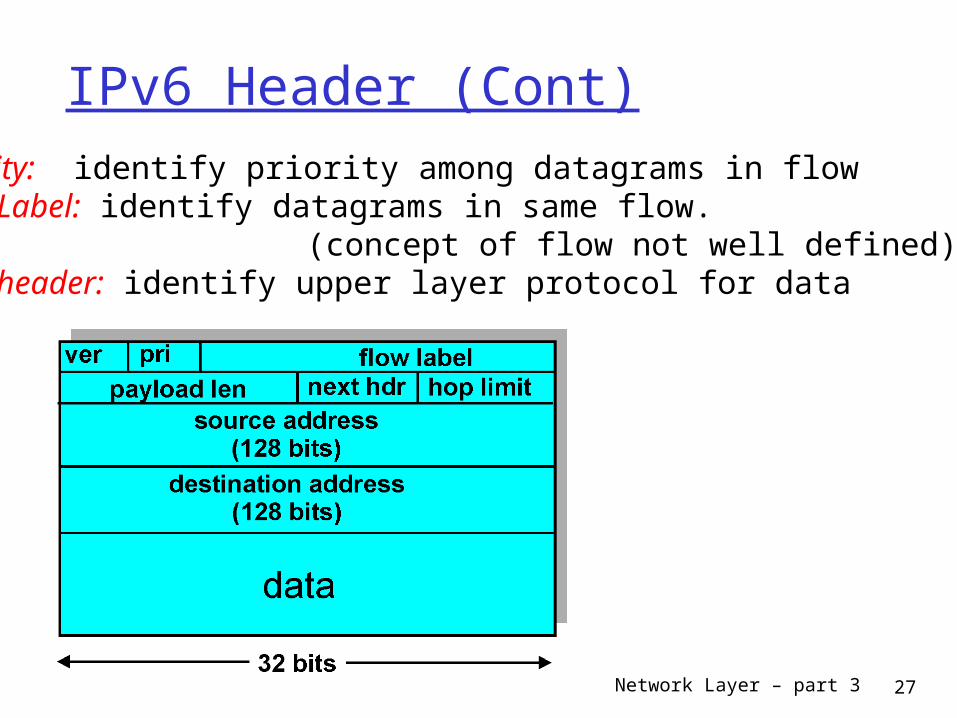
IPv6 Header (Cont)Priority: identify priority among datagrams in flowFlow Label: identify datagrams in same flow. (concept of flow not well defined).Next header: identify upper layer protocol for data

Network Layer – part 3 28
Other Changes from IPv4
Checksum: removed entirely to reduce processing time at each hop
Options: allowed, but outside of header, indicated by Next Header field
ICMPv6: new version of ICMP additional message types, e.g. ''Packet Too
Big'' multicast group management functions
Network Layer – part 3 29
Transition From IPv4 To IPv6
Not all routers can be upgraded simultaneously no flag days How will the network operate with mixed
IPv4 and IPv6 routers? Two proposed approaches:
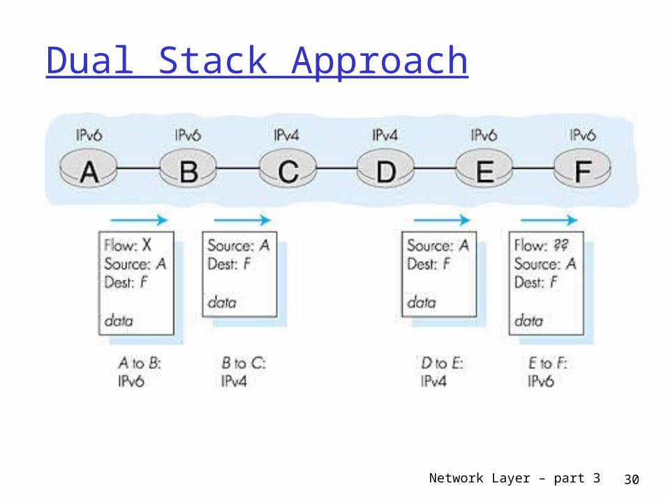
Dual Stack: some routers with dual stack (v6, v4) can translate between formats
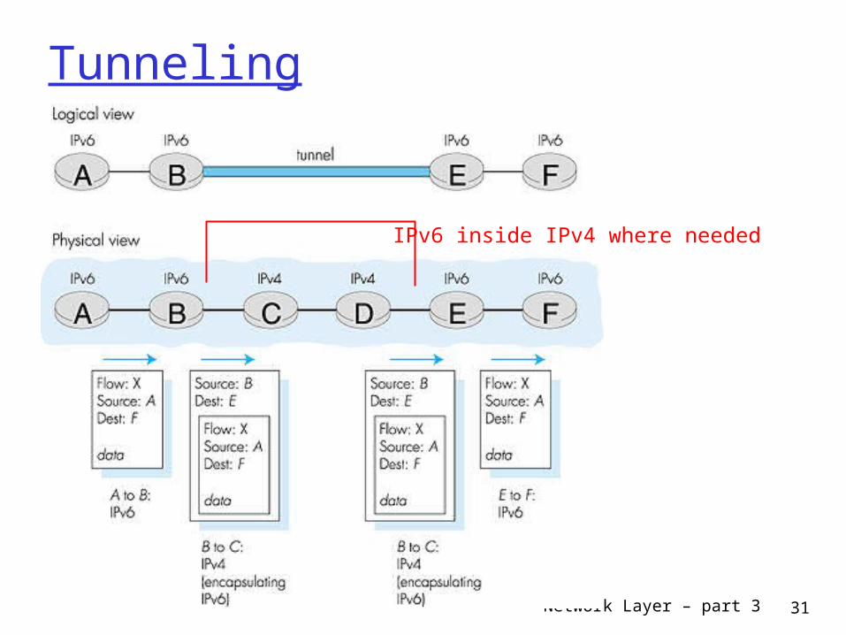
Tunneling: IPv6 carried as payload in IPv4 datagram among IPv4 routers
Network Layer – part 3 30
Dual Stack Approach
Network Layer – part 3 31
Tunneling
IPv6 inside IPv4 where needed