Embed Size (px)
Citation preview
Tivoli® Decision Support for z/OS®
Network Performance Feature
Installation and Administration
Version 1.7
SH19-6901-08
���


Tivoli® Decision Support for z/OS®
Network Performance Feature
Installation and Administration
Version 1.7
SH19-6901-08
���
Note
Before using this information and the product it supports, read the information in “Notices” on page 181″.
Ninth Edition (November 2004)
This edition applies to version 1, release 7 of Tivoli Decision Support for z/OS (program number 5698-A07) and to
all subsequent releases and modifications until otherwise indicated in new editions.
This edition replaces SH19-6901-07.
© Copyright International Business Machines Corporation 1993, 2004. All rights reserved.
Note to U.S. Government Users Restricted Rights—Use, duplication or disclosure restricted by GSA ADP Schedule
Contract with IBM Corporation.
Contents
Figures . . . . . . . . . . . . . . vii
Preface . . . . . . . . . . . . . . . ix
Who should read this book . . . . . . . . . ix
What this book contains . . . . . . . . . . ix
Publications . . . . . . . . . . . . . . x
Tivoli Decision Support for z/OS library . . . . x
Using LookAt to look up message explanations . xi
Accessing publications online . . . . . . . xii
Ordering publications . . . . . . . . . . xii
Accessibility . . . . . . . . . . . . . . xii
Tivoli technical training . . . . . . . . . . xii
Contacting IBM Software Support . . . . . . . xii
Determine the business impact of your problem xiii
Describe your problem and gather background
information . . . . . . . . . . . . . xiv
Submit your problem to IBM Software Support xiv
Searching knowledge bases . . . . . . . . xiv
Search the information center on your local
system or network . . . . . . . . . . xiv
Search the Internet . . . . . . . . . . xiv
Obtaining fixes . . . . . . . . . . . . xv
Updating support information . . . . . . . xv
Conventions used in this book . . . . . . . . xvi
Typeface conventions . . . . . . . . . . xvi
Changes in this edition . . . . . . . . . . xvi
Chapter 1. Introducing the Tivoli
Decision Support for z/OS Network
Performance feature . . . . . . . . . 1
Meeting users’ needs . . . . . . . . . . . 1
Implementing the solution . . . . . . . . . . 2
Selecting required data in Tivoli Decision Support for
z/OS . . . . . . . . . . . . . . . . . 4
Defining the network environment . . . . . . . 6
Understanding Network Performance feature tasks . 7
Chapter 2. Planning . . . . . . . . . . 9
Understanding the planning process . . . . . . 9
Planning for installation . . . . . . . . . . 10
Planning for components . . . . . . . . . . 11
Understanding environment information . . . . 13
Maintaining the environment information . . . 14
Understanding resource information . . . . . 14
Sources of resource data . . . . . . . . 15
Describing resources . . . . . . . . . 15
Grouping resources . . . . . . . . . . 16
Defining synonym names . . . . . . . . 18
Defining application synonyms . . . . . 18
Defining NCP synonyms . . . . . . . 19
Defining cross-domain or cross-network
connection synonyms . . . . . . . . 19
Including resources in availability processing 19
Understanding resource connections . . . . 20
Establishing service-level objectives . . . . 20
Understanding threshold information . . . . . 21
Understanding period information . . . . . . 22
Understanding schedule information . . . . . 24
Understanding product ID information . . . . 26
Understanding code converter information . . . 27
Basic alert code converter tables . . . . . 27
Generic alert code converter tables . . . . 28
Session failure code converter . . . . . . 29
Planning tasks for each component . . . . . . 30
Availability . . . . . . . . . . . . . 30
Describing resources . . . . . . . . . 30
Grouping resources . . . . . . . . . . 30
Including resources . . . . . . . . . . 30
Creating synonym names . . . . . . . . 31
Establishing service objectives . . . . . . 31
Creating schedules . . . . . . . . . . 31
Customizing NetView . . . . . . . . . 31
Special considerations for cross-connection
resources . . . . . . . . . . . . . 32
Configuration . . . . . . . . . . . . 32
NetView FTP . . . . . . . . . . . . . 32
SMF record type . . . . . . . . . . . 32
Problem . . . . . . . . . . . . . . 32
Session failure . . . . . . . . . . . . 33
RTM response time . . . . . . . . . . . 33
Describing resources . . . . . . . . . 33
Grouping resources . . . . . . . . . . 33
Creating synonym names . . . . . . . . 33
Establishing service objectives . . . . . . 33
Customizing NetView . . . . . . . . . 34
NPM transit time . . . . . . . . . . . 34
Describing resources . . . . . . . . . 35
Grouping resources . . . . . . . . . . 35
Creating synonym names . . . . . . . . 35
Establishing service objectives . . . . . . 35
Customizing NPM . . . . . . . . . . 36
Service . . . . . . . . . . . . . . . 36
Line utilization . . . . . . . . . . . . 36
Verifying threshold setting . . . . . . . 37
Customizing NPM . . . . . . . . . . 38
NCP utilization . . . . . . . . . . . . 38
Describing resources . . . . . . . . . 38
Grouping resources . . . . . . . . . . 38
Creating synonym names . . . . . . . . 38
Customizing NPM . . . . . . . . . . 39
NPM internal utilization . . . . . . . . . 39
NPM name . . . . . . . . . . . . 39
Collect interval . . . . . . . . . . . 39
Customizing NPM . . . . . . . . . . 39
PU utilization . . . . . . . . . . . . 39
NV/SM utilization . . . . . . . . . . . 39
NetView name . . . . . . . . . . . 40
Customizing NetView . . . . . . . . . 40
NEO utilization . . . . . . . . . . . . 40
Describing resources . . . . . . . . . 40
iii
||
||||||||||||||||||||||
Creating synonym names . . . . . . . . 40
Verifying threshold setting . . . . . . . 40
Customizing NPM . . . . . . . . . . 41
NTRI utilization . . . . . . . . . . . . 42
Describing resources . . . . . . . . . 42
Creating synonym names . . . . . . . . 42
Customizing NPM . . . . . . . . . . 42
Frame Relay utilization . . . . . . . . . 42
Describing resources . . . . . . . . . 43
Creating synonym names . . . . . . . . 43
Customizing NPM . . . . . . . . . . 43
LAN utilization . . . . . . . . . . . . 43
Customizing NPM . . . . . . . . . . 43
ODLC utilization . . . . . . . . . . . 44
Describing resources . . . . . . . . . 44
Creating synonym names . . . . . . . . 44
Customizing NPM . . . . . . . . . . 44
VTAM utilization . . . . . . . . . . . 44
X.25 utilization . . . . . . . . . . . . 44
Describing resources . . . . . . . . . 45
Creating synonym names . . . . . . . . 45
Verifying threshold setting . . . . . . . 45
Customizing NPM . . . . . . . . . . 46
SNMP routers utilization . . . . . . . . . 46
Customizing NPM . . . . . . . . . . 47
Chapter 3. Installing the Network
Performance feature . . . . . . . . . 49
Installing the feature . . . . . . . . . . . 49
Changing the dialog parameters . . . . . . . 49
Installing Tivoli Decision Support for z/OS
components . . . . . . . . . . . . . . 50
Chapter 4. Administering Tivoli
Decision Support for z/OS and the
Network Performance feature . . . . . 55
Administering resource information . . . . . . 55
Administration dialog direct-edit method . . . 56
Advantages . . . . . . . . . . . . 56
Disadvantages . . . . . . . . . . . 56
Network administration dialog . . . . . . . 56
Administering threshold information . . . . . 57
Administering period tables . . . . . . . . 57
Administering the schedule table . . . . . . 57
Administering the product ID table . . . . . 58
Administering code converter tables . . . . . 58
Chapter 5. Working with the Network
Performance feature Administration
dialog . . . . . . . . . . . . . . . 61
Understanding the need for the network
administration dialog . . . . . . . . . . . 61
Network administration dialog functions . . . . 61
Work table . . . . . . . . . . . . . . 62
Loading data into the work table . . . . . 63
Updating the NW_RESOURCE table . . . . 64
Exporting data . . . . . . . . . . . 64
Performance considerations . . . . . . . 64
STATMON loader . . . . . . . . . . . 65
Resource defaults . . . . . . . . . . 65
Definition rules . . . . . . . . . . . 65
Import . . . . . . . . . . . . . . . 65
Editor . . . . . . . . . . . . . . . 66
Export . . . . . . . . . . . . . . . 66
Verify . . . . . . . . . . . . . . . 66
Database update . . . . . . . . . . . . 67
Database loader . . . . . . . . . . . . 67
Overview of administration dialog tasks . . . . . 67
Administration tasks with STATMON data . . . 67
Administration tasks with data from an external
source . . . . . . . . . . . . . . . 68
Working with STATMON data . . . . . . . . 68
Producing resource data using STATMON . . . 69
Loading STATMON data into the work table . . 69
Changing resource information . . . . . . . 73
Updating the database . . . . . . . . . . 73
Loading data from multiple domains into
NW_RESOURCE . . . . . . . . . . . . 75
Loading STATMON data from the first domain 76
Loading STATMON data from the second
domain . . . . . . . . . . . . . . . 76
Changing resource data . . . . . . . . . . 77
Loading data from the database . . . . . . 79
Modifying resource information . . . . . . 80
Displaying resources . . . . . . . . . . 81
Using the Search1 function key . . . . . . . 82
Using the Search2 function key . . . . . . . 83
Using the Change function key . . . . . . . 85
Deleting individual resource entries . . . . . 86
Using the save command . . . . . . . . . 86
Using the deleteall command . . . . . . . 87
Changing individual resource entries . . . . . 87
Changing application data . . . . . . . 90
Changing NCP resource data . . . . . . 92
Changing line resource data . . . . . . . 93
Changing cluster resource data . . . . . . 94
Changing cross-connection resource data . . 95
Changing group resource data . . . . . . 96
Changing local resource data . . . . . . 97
Changing switched resource data . . . . . 98
Verifying resource data . . . . . . . . . 98
Updating the database . . . . . . . . . . 99
Adding resource data to NW_RESOURCE . . . . 99
Adding resource data using the editing function 100
Adding resource data using STATMON . . . 100
Loading data from an external source into
NW_RESOURCE . . . . . . . . . . . . 102
Producing resource data using an external
source . . . . . . . . . . . . . . . 103
Setting defaults for external data . . . . . . 103
Loading external data into the work table . . . 104
Updating the database . . . . . . . . . 105
Exporting data from the NW_RESOURCE table 105
Chapter 6. Administration Dialog
Example . . . . . . . . . . . . . 109
Understanding the sample network . . . . . . 109
Administration tasks for the sample data . . . 110
Loading the resource data for domain 1 . . . . 112
Gathering network resource data . . . . . . 112
iv Tivoli Decision Support for z/OS: Network Performance Feature Installation and Administration
Setting the resource default values and loading
the data . . . . . . . . . . . . . . 112
Modifying resource data for domain 1 . . . . . 116
Changing the NCP resource data . . . . . . 116
Changing application resources environment
data . . . . . . . . . . . . . . . 122
Changing resource data to group lines and
clusters . . . . . . . . . . . . . . 125
Changing the cross-connection resource
environment data . . . . . . . . . . . 128
Updating the Tivoli Decision Support for z/OS
database . . . . . . . . . . . . . . 131
Updating the network environment for domain 2 133
Changing domain 2 environment data and
updating the database . . . . . . . . . 136
Defining complex network environments . . . . 136
Deleting the sample data . . . . . . . . . 139
Chapter 7. Customizing NetView and
NPM . . . . . . . . . . . . . . . 141
Customizing NetView . . . . . . . . . . 141
Determining NetView customization tasks . . . 141
nv1—Define SMF logging in NetView . . . . 142
nv2—Collect NetView session awareness data 142
nv3—Log NetView session awareness data to
SMF . . . . . . . . . . . . . . . 142
nv4—Reduce the CPU and storage utilization in
the session monitor . . . . . . . . . . 143
nv5—Collect session statistics for active sessions 143
nv6—Collect RTM data in NetView session
monitor . . . . . . . . . . . . . . 143
nv7—Log NetView session monitor RTM data to
SMF . . . . . . . . . . . . . . . 143
nv8—Collect RTM data and log to SMF . . . 143
nv9—Define RTM performance classes . . . . 143
nv10—Customize cluster controllers for RTM 144
nv11—Collect session monitor utilization data 144
nv12—Start and stop hardware monitor logging 144
nv13—Collect session failure data in NetView
session monitor . . . . . . . . . . . . 144
nv14—Activate the network asset management
function . . . . . . . . . . . . . . 144
nv15—Collect configuration data . . . . . . 144
Customizing NPM . . . . . . . . . . . 145
Determining NPM customization tasks . . . . 145
npm1—SMF logging . . . . . . . . . . 146
npm2—Log session interval records to SMF . . 146
npm3—NPM collect interval . . . . . . . 146
npm4—Define the base interval . . . . . . 149
npm5—Define the interval synchronization . . 149
npm6—Define the session collect interval . . . 149
npm7—Collect network data . . . . . . . 150
npm8—Define NCP to NPM . . . . . . . 150
npm9—Collect network data . . . . . . . 150
The START COLLECT command . . . . . 150
The NETCOLL command . . . . . . . 151
npm10—Enable network collection . . . . . 151
npm11—Verify line speed . . . . . . . . 151
npm12—Collect transit time . . . . . . . 151
npm13—Define NPM APPL statements . . . . 152
npm14—Define transit-time objective . . . . 152
npm15—Collect session data for each resource 152
npm16—Enable LAN data collection . . . . 153
npm17—Define LAN Managers . . . . . . 153
npm18—Define the LAN collection interval . . 153
npm19—Collect LAN bridge data . . . . . 155
npm20—Collect LAN segment data . . . . . 155
npm21—Enable VTAM data collection . . . . 155
npm22—Changing the VTAM interval . . . . 156
npm23—Collect VTAM data . . . . . . . 156
npm24—Define routers to NPM . . . . . . 156
npm25—Collect network data for SNMP routers 157
The IPCOLL command . . . . . . . . 157
Chapter 8. Testing and maintaining
the Network Performance feature . . . 159
Testing the Network Performance feature . . . . 159
Collecting data . . . . . . . . . . . . 159
Generating reports . . . . . . . . . . 159
Evaluating test data . . . . . . . . . . . 160
Checking SMF records . . . . . . . . . 160
Moving the feature into production . . . . . . 162
Collecting data in production . . . . . . . 163
Purging data . . . . . . . . . . . . 163
Creating reports in production . . . . . . 164
Performing maintenance . . . . . . . . . . 164
Keeping resource information current . . . . 164
Performing maintenance with STATMON 164
Performing maintenance with an external
source . . . . . . . . . . . . . . 166
Appendix A. Sample STATMON Inputs
and Outputs . . . . . . . . . . . . 167
VTAMLST input to STATMON . . . . . . . 167
STATMON output . . . . . . . . . . . . 168
Appendix B. External Data File Format 171
Appendix C. Using the DRLENR2X
User Exit . . . . . . . . . . . . . 175
Appendix D. List of abbreviations . . 179
Notices . . . . . . . . . . . . . . 181
Trademarks . . . . . . . . . . . . . . 183
Glossary . . . . . . . . . . . . . 185
Index . . . . . . . . . . . . . . . 187
Contents v

vi Tivoli Decision Support for z/OS: Network Performance Feature Installation and Administration
Figures
1. The need for a network management product 1
2. Organizing and presenting network data . . . 2
3. Environment information . . . . . . . . 6
4. Network Performance feature tasks . . . . . 7
5. Role of planning . . . . . . . . . . . 9
6. Basic component planning process . . . . . 12
7. Resource grouping example . . . . . . . 17
8. Resource grouping and alternate resource
grouping . . . . . . . . . . . . . 17
9. Reports with changing NCP names . . . . 19
10. Synonym name for changing NCP names 19
11. NW_THRESHOLD format . . . . . . . 22
12. Example SPECIAL_DAY table . . . . . . 22
13. Example DAY_OF_WEEK table . . . . . . 23
14. Example PERIOD_PLAN table . . . . . . 23
15. Example SCHEDULE table . . . . . . . 25
16. Example AVAILABILITY_PARM table . . . . 25
17. Example NW_PRODUCT_ID table . . . . . 27
18. Example basic alert code converter table 28
19. Example generic alert code converter table 29
20. Example NW_FAILURE_CODE table . . . . 29
21. Example NW_THRESHOLD table . . . . . 37
22. Example NW_THRESHOLD table . . . . . 41
23. Example NW_THRESHOLD table . . . . . 46
24. Selecting the component window . . . . . 49
25. Selecting the system parameters window 50
26. Components w indow . . . . . . . . . 50
27. Component Parts window . . . . . . . 51
28. Installation Options window . . . . . . . 51
29. Lookup Tables window. For non-QMF users,
F5 and F6 are not available. . . . . . . . 52
30. Role of environment information . . . . . 55
31. Methods of maintaining NW_RESOURCE data 56
32. ISPF work table and the Tivoli Decision
Support for z/OS database . . . . . . . 62
33. ISPF work table and the Tivoli Decision
Support for z/OS database . . . . . . . 63
34. ISPF work table and the Tivoli Decision
Support for z/OS database . . . . . . . 64
35. Exporting data from the NW_RESOURCE table 64
36. STATMON loader . . . . . . . . . . 65
37. Window flow: Loading STATMON data 69
38. Network Administration Primary Option
window . . . . . . . . . . . . . . 70
39. Set Defaults and Load Data window . . . . 70
40. Edit Resource Defaults window . . . . . . 71
41. Load Options window . . . . . . . . . 73
42. Window flow: Updating the database . . . . 74
43. Tivoli Decision Support for z/OS Database
Update window . . . . . . . . . . . 74
44. Process Tivoli Decision Support for z/OS
Statements window . . . . . . . . . . 75
45. Loading data from one domain at a time 76
46. Changing existing data . . . . . . . . . 78
47. Window flow: Changing existing data . . . 79
48. Loading data from the Tivoli Decision Support
for z/OS database . . . . . . . . . . 79
49. Loading data from the database into the work
table . . . . . . . . . . . . . . . 80
50. Windows for changing resource information 81
51. Change Resource Data window . . . . . . 82
52. Changing the selection list using Search1 82
53. Set Search1 Values window . . . . . . . 83
54. Changing the selection list using Search2 84
55. Set Search2 Values window . . . . . . . 84
56. Set Global Change Values window . . . . . 86
57. Multiple task with TSO . . . . . . . . 89
58. Confirm Changes pop-up . . . . . . . . 90
59. Change Application Resource Data window 91
60. Change NCP Resource Data window . . . . 92
61. Change Line Resource Data window . . . . 93
62. Change Cluster Resource Data window 94
63. Change Cross-connection Resource Data
window . . . . . . . . . . . . . . 95
64. Change Group Resource Data window . . . 96
65. Change Local Resource Data window . . . . 97
66. Change Switched Resource Data window 98
67. Confirm Selection pop-up . . . . . . . . 99
68. Specify a New Resource window . . . . . 100
69. Merging new STATMON data into the
database . . . . . . . . . . . . . 101
70. Loading data from an external source 102
71. Window flow: Loading external data 103
72. Edit Resource Defaults window . . . . . 104
73. Define Data Set Name window . . . . . 105
74. Window flow: Exporting data . . . . . . 106
75. Define Data Set Name window . . . . . 106
76. Sample network configuration . . . . . . 110
77. Network Administration Primary Option
window . . . . . . . . . . . . . 112
78. List of defined systems . . . . . . . . 113
79. Resource default values for a new system 114
80. Load options window . . . . . . . . . 115
81. Confirmation of successful load of STATMON
data . . . . . . . . . . . . . . . 115
82. Initial Change Resource Data window 117
83. Search for all resources with NCP = UCX4 117
84. Selection list of resources attached to NCP
UCX4 . . . . . . . . . . . . . . 118
85. Change NCP Resource Data window 118
86. Hierarchical links between NCP, lines, and
clusters . . . . . . . . . . . . . 119
87. Changing NCP fields to NCPUCX . . . . 120
88. Adding a new NCP entry . . . . . . . 121
89. UCX2 resource entry . . . . . . . . . 121
90. Resource and synonym pointers . . . . . 122
91. Selection list of all resources in group
ATSOMAJ . . . . . . . . . . . . 123
92. Application resource entry . . . . . . . 124
93. Selection list of all resources where line =
V40LKNF8 . . . . . . . . . . . . 125
vii
94. Connecting resources to group LONDON1 126
95. Adding a new group entry . . . . . . . 127
96. Defining the geographic group entry 127
97. Search for all cross-connection resources 128
98. List of cross-connection resources . . . . . 129
99. Cross-connection resource entry for CDR2 130
100. Changed cross-connection resource entry for
CDR2 . . . . . . . . . . . . . . 130
101. Confirming the verification of the work table 131
102. Selecting the system for database update 132
103. Processing database update statements 133
104. List of defined systems . . . . . . . . 134
105. Resource default values for a new system 134
106. Load Options window . . . . . . . . 135
107. Confirmation of successful load of STATMON
data . . . . . . . . . . . . . . . 136
108. Example of a complex network configuration 137
109. Definitions in work table for complex
network . . . . . . . . . . . . . 138
110. Example of a complex network using NPM 139
111. Deleting the sample data . . . . . . . . 140
112. Line utilization example A . . . . . . . 147
113. Line utilization example B . . . . . . . 147
114. Example of collect intervals . . . . . . . 149
115. SMF checking output—records processed by
record definition . . . . . . . . . . 161
116. SMF checking output—subtypes listed 161
117. Database tasks . . . . . . . . . . . 162
118. Specifying the system to edit . . . . . . 165
119. Load Options window . . . . . . . . 165
viii Tivoli Decision Support for z/OS: Network Performance Feature Installation and Administration
Preface
This book provides a brief introduction to the Network Performance feature of
IBM® Tivoli® Decision Support for z/OS® (hereafter referred to as Tivoli Decision
Support for z/OS). It describes the planning necessary for the feature, and
procedures required to install the feature and administer the information in the
database tables. This book also contains an administration example that uses the
sample data supplied with the feature code.
Tivoli Decision Support for z/OS was previously known as Tivoli Decision Support
for OS/390®.
The following terms are used interchangeably throughout this book:
v Tivoli Decision Support for z/OS and Tivoli Decision Support for OS/390
v MVS™, OS/390, and z/OS
v OPC and Tivoli Workload Scheduler for z/OS
Who should read this book
Network Performance Feature Installation and Administration is for network analysts or
programmers who are responsible for setting up the network reporting
environment.
What this book contains
Use this book as a guide to installing and administering the Network Performance
feature. The book contains these chapters:
v Chapter 1, “Introducing the Tivoli Decision Support for z/OS Network
Performance feature” introduces the Network Performance feature, describes
how the feature works with network data, and summarizes the installation and
administration procedure described in the remainder of the book.
v Chapter 2, “Planning” describes the process required to plan for installing the
Network Performance feature and explains how to determine what parts of the
feature you need to install, and the planning and customization required for
each part.
v Chapter 3, “Installing the Network Performance feature” describes the procedure
for installing the Network Performance feature.
v Chapter 4, “Administering Tivoli Decision Support for z/OS and the Network
Performance feature” provides an overview of the administration process
required for the Network Performance feature. The chapter introduces the tasks
you must perform using the network administration dialog and the tasks you
must perform using the Tivoli Decision Support for z/OS administration dialog.
v Chapter 5, “Working with the Network Performance feature Administration
dialog” explains how to use the network administration dialog to work with
network resource data.
v Chapter 6, “Administration Dialog Example” uses the sample data provided
with the feature to illustrate some of the tasks you must perform with the
network administration dialog.
ix
||
|
|
|
|
v Chapter 7, “Customizing NetView and NPM” lists the modifications you must
make to NetView® and NPM for the Network Performance feature to be able to
collect data accurately.
v Chapter 8, “Testing and maintaining the Network Performance feature” provides
information on moving the Network Performance feature into production.
This book contains the following appendixes:
v Appendix A, “Sample STATMON Inputs and Outputs”
v Appendix B, “External Data File Format”
v Appendix C, “Using the DRLENR2X User Exit”
This book also contains a list of abbreviations, a glossary, and an index.
Publications
This section lists publications in the Tivoli Decision Support for z/OS library and
any other related documents. It also describes how to access Tivoli publications
online, how to order Tivoli publications, and how to submit comments on Tivoli
publications.
Tivoli Decision Support for z/OS library
This section lists publications in the Tivoli Decision Support for z/OS library and
any other related documents. It also describes how to access Tivoli publications
online and how to order Tivoli publications.
v Accounting Feature for z/OS, SH19-4495
Provides information for users who want to use Tivoli Decision Support for
z/OS to collect and report performance data generated by the Accounting
feature.
v Administration Guide, SH19-6816
Provides information about initializing the Tivoli Decision Support for z/OS
database and customizing and administering Tivoli Decision Support for z/OS.
v AS/400 System Performance Feature Guide and Reference, SH19-4019
Provides information for administrators and users about collecting and reporting
performance data generated by AS/400® systems.
v CICS Performance Feature Guide and Reference, SH19-6820
Provides information for administrators and users about collecting and reporting
performance data generated by Customer Information and Control System
(CICS®).
v Distributed Systems Performance Feature Guide and Reference, SH19-4018
Provides information for administrators and users about collecting and reporting
performance data generated by operating systems and applications running on a
workstation.
v Guide to the Reporting Dialog, SH19-6842
Provides information for users who display existing reports, for users who create
and modify reports, and for administrators who control reporting dialog default
functions and capabilities.
v IMS Performance Feature Guide and Reference, SH19-6825
Provides information for administrators and users about collecting and reporting
performance data generated by Information Management System (IMS™).
v Language Guide and Reference, SH19-6817
x Tivoli Decision Support for z/OS: Network Performance Feature Installation and Administration
Provides information for administrators, performance analysts, and
programmers who are responsible for maintaining system log data and reports.
v Messages and Problem Determination, SH19-6902
Provides information to help operators and system programmers understand,
interpret, and respond to Tivoli Decision Support for z/OS messages and codes.
v Network Performance Feature Installation and Administration, SH19-6901
Provides information for network analysts or programmers who are responsible
for setting up the network reporting environment.
v Network Performance Feature Reference, SH19-6822
Provides information for network analysts or programmers who are responsible
for setting up the network reporting environment.
v Network Performance Feature Reports, SH19-6821
Provides information for network analysts or programmers who use the
Network Performance feature reports.
v System Performance Feature Guide, SH19-6818
Provides information for performance analysts and system programmers who
are responsible for meeting the service-level objectives established in your
organization.
v System Performance Feature Reference Volume I, SH19-6819
Provides information for administrators and users with a variety of backgrounds
who want to use Tivoli Decision Support for z/OS to analyze Multiple Virtual
Storage (MVS) or Virtual Machine (VM) performance data.
v System Performance Feature Reference Volume II, SH19-4494
Provides information for administrators and users with a variety of backgrounds
who want to use Tivoli Decision Support for z/OS to analyze Multiple Virtual
Storage (MVS)or Virtual Machine (VM) performance data.
v IBM Online Library z/OS Software Products Collection Kit, SK3T-4270
CD containing all z/OS documentation.
The Tivoli Software Glossary includes definitions for many of the technical terms
related to Tivoli software. The Tivoli Software Glossary is available, in English only,
at the following Web site:
http://publib.boulder.ibm.com/tividd/glossary/termsmst04.htm
Using LookAt to look up message explanations
LookAt is an online facility that lets you look up explanations for most messages
you encounter, as well as for some system abends and codes. Using LookAt to find
information is faster than a conventional search because in most cases LookAt goes
directly to the message explanation.
You can access LookAt from the Internet at:
http://www.ibm.com/eserver/zseries/zos/bkserv/lookat/ or from anywhere in
z/OS or z/OS.e where you can access a TSO/E command line (for example,
TSO/E prompt, ISPF, z/OS UNIX® System Services running OMVS).
The LookAt Web site also features a mobile edition of LookAt for devices such as
Pocket PCs, Palm OS, or Linux™-based handhelds. So, if you have a handheld
device with wireless access and an Internet browser, you can now access LookAt
message information from almost anywhere.
Preface xi
To use LookAt as a TSO/E command, you must have LookAt installed on your
host system.
Accessing publications online
IBM posts publications for this and all other Tivoli products, as they become
available and whenever they are updated, to the Tivoli software information center
Web site. Access the Tivoli software information center by first going to the Tivoli
software library at the following Web address:
http://publib.boulder.ibm.com/tiviid/td/tdprodlist.html
Scroll down and click the Product manuals link. In the Tivoli Technical Product
Documents Alphabetical Listing window, click the Tivoli Decision Support for
z/OS link to access the product library at the Tivoli software information center.
Note: If you print PDF documents on other than letter-sized paper, set the option
in the File ” Print window that allows Adobe Reader to print letter-sized
pages on your local paper.
Ordering publications
You can order many Tivoli publications online at the following Web
site:http://www.elink.ibmlink.ibm.com/public/applications/publications/
cgibin/pbi.cgi
You can also order by telephone by calling one of these numbers:
v In the United States: 800-879-2755
v In Canada: 800-426-4968
In other countries, see the following Web site for a list of telephone numbers:
http://www.ibm.com/software/tivoli/order-lit/
Accessibility
Accessibility features help users with a physical disability, such as restricted
mobility or limited vision, to use software products successfully. With this product,
you can use assistive technologies to hear and navigate the interface.You can also
use the keyboard instead of the mouse to operate all features of the graphical user
interface.
For additional information, see the Accessibility Appendix in the Administration
Guide.
Tivoli technical training
For Tivoli technical training information, refer to the following IBM Tivoli
Education Web site:
http://www.ibm.com/software/tivoli/education/
Contacting IBM Software Support
IBM Software Support provides assistance with product defects.
xii Tivoli Decision Support for z/OS: Network Performance Feature Installation and Administration
|
||||
|
|||
|||
|
||
|
|
|
Before contacting IBM Software Support, your company must have an active IBM
software maintenance contract, and you must be authorized to submit problems to
IBM. The type of software maintenance contract that you need depends on the
type of product you have:
v For IBM distributed software products (including, but not limited to, Tivoli,
Lotus®, and Rational® products, as well as DB2® and WebSphere® products that
run on Windows® or UNIX operating systems), enroll in Passport Advantage® in
one of the following ways:
– Online: Go to the Passport Advantage Web page
(http://www.lotus.com/services/passport.nsf/WebDocs/
Passport_Advantage_Home) and click How to Enroll
– By phone: For the phone number to call in your country, go to the IBM
Software Support Web site
(http://techsupport.services.ibm.com/guides/contacts.html) and click the
name of your geographic region.v For IBM eServer™ software products (including, but not limited to, DB2 and
WebSphere products that run in zSeries®, pSeries®, and iSeries® environments),
you can purchase a software maintenance agreement by working directly with
an IBM sales representative or an IBM Business Partner. For more information
about support for eServer software products, go to the IBM Technical Support
Advantage Web page (http://www.ibm.com/servers/eserver/techsupport.html).
If you are not sure what type of software maintenance contract you need, call
1-800-IBMSERV (1-800-426-7378) in the United States or, from other countries, go to
the contacts page of the IBM Software Support Handbook on the Web
(http://techsupport.services.ibm.com/guides/contacts.html) and click the name of
your geographic region for phone numbers of people who provide support for
your location.
Follow the steps in this topic to contact IBM Software Support:
1. “Determine the business impact of your problem”
2. “Describe your problem and gather background information” on page xiv
3. “Submit your problem to IBM Software Support” on page xiv
Determine the business impact of your problem
When you report a problem to IBM, you are asked to supply a severity level.
Therefore, you need to understand and assess the business impact of the problem
you are reporting. Use the following criteria:
Severity 1 Critical business impact: You are unable to use the program,
resulting in a critical impact on operations. This condition
requires an immediate solution.
Severity 2 Significant business impact: The program is usable but is
severely limited.
Severity 3 Some business impact: The program is usable with less
significant features (not critical to operations) unavailable.
Severity 4 Minimal business impact: The problem causes little impact on
operations, or a reasonable circumvention to the problem has
been implemented.
Contacting IBM Software Support
Preface xiii
||||
||||
|||
||||
||||||
||||||
|
|
|
|
|
|||
|||||
|||
|||
|||||
Describe your problem and gather background information
When explaining a problem to IBM, be as specific as possible. Include all relevant
background information so that IBM Software Support specialists can help you
solve the problem efficiently. To save time, know the answers to these questions:
v What software versions were you running when the problem occurred?
v Do you have logs, traces, and messages that are related to the problem
symptoms? IBM Software Support is likely to ask for this information.
v Can the problem be recreated? If so, what steps led to the failure?
v Have any changes been made to the system? (For example, hardware, operating
system, networking software, and so on.)
v Are you currently using a workaround for this problem? If so, please be
prepared to explain it when you report the problem.
Submit your problem to IBM Software Support
You can submit your problem in one of two ways:
v Online: Go to the ″Submit and track problems″ page on the IBM Software
Support site (http://www.ibm.com/software/support/probsub.html). Enter
your information into the appropriate problem submission tool.
v By phone: For the phone number to call in your country, go to the contacts page
of the IBM Software Support Handbook on the Web
(http://techsupport.services.ibm.com/guides/contacts.html) and click the name
of your geographic region.
If the problem you submit is for a software defect or for missing or inaccurate
documentation, IBM Software Support creates an Authorized Program Analysis
Report (APAR). The APAR describes the problem in detail. Whenever possible,
IBM Software Support provides a workaround for you to implement until the
APAR is resolved and a fix is delivered. IBM publishes resolved APARs on the
IBM product support Web pages daily, so that other users who experience the
same problem can benefit from the same resolutions.
For more information about problem resolution, see “Searching knowledge bases”
and “Obtaining fixes” on page xv.
Searching knowledge bases
If you have a problem with your IBM software, you want it resolved quickly. Begin
by searching the available knowledge bases to determine whether the resolution to
your problem is already documented.
Search the information center on your local system or network
IBM provides extensive documentation that can be installed on your local machine
or on an intranet server. You can use the search function of this information center
to query conceptual information, instructions for completing tasks, reference
information, and support documents.
Search the Internet
If you cannot find an answer to your question in the information center, search the
Internet for the latest, most complete information that might help you resolve your
problem. To search multiple Internet resources for your product, expand the
product folder in the navigation frame to the left and select Support on the Web.
From this topic, you can search a variety of resources including:
v IBM technotes
Contacting IBM Software Support
xiv Tivoli Decision Support for z/OS: Network Performance Feature Installation and Administration
|
|||
|
||
|
||
||
|
|
|||
||||
|||||||
||
|
|||
|||||
||||||
|
v IBM downloads
v IBM Redbooks™
v IBM DeveloperWorks
v Forums and newsgroups
v Google
Obtaining fixes
A product fix might be available to resolve your problem. You can determine what
fixes are available for your IBM software product by checking the product support
Web site:
1. Go to the IBM Software Support Web site
(http://www.ibm.com/software/support).
2. Under Products A - Z, select your product name. This opens a product-specific
support site.
3. Under Self help, follow the link to All Updates, where you will find a list of
fixes, fix packs, and other service updates for your product. For tips on refining
your search, click Search tips.
4. Click the name of a fix to read the description and optionally download the fix.
To receive weekly e-mail notifications about fixes and other news about IBM
products, follow these steps:
1. From the support page for any IBM product, click My support in the
upper-right corner of the page.
2. If you have already registered, skip to the next step. If you have not registered,
click register in the upper-right corner of the support page to establish your
user ID and password.
3. Sign in to My support.
4. On the My support page, click Edit profiles in the left navigation pane, and
scroll to Select Mail Preferences. Select a product family and check the
appropriate boxes for the type of information you want.
5. Click Submit.
6. For e-mail notification for other products, repeat Steps 4 and 5.
For more information about types of fixes, see the Software Support Handbook
(http://techsupport.services.ibm.com/guides/handbook.html).
Updating support information
Information centers typically include one or more support information plug-ins.
These plug-ins add IBM technotes and other support documents to the information
center. The following steps describe how to update your support information
plug-ins:
1. Go to the IBM Software Support Web site
(http://www.ibm.com/software/support).
2. Under Products A - Z, select your product name. This opens a product-specific
support site.
3. Under Search support for this product, type the keyword phrase:
com.ibm.support. Click the Download check box, and click Submit.
4. Check the search results for updates to support information plug-ins. All
support information plug-ins follow the naming convention,
″com.ibm.support.product.doc.″ If an update is available, select it from the list
and view the download instructions.
Contacting IBM Software Support
Preface xv
|
|
|
|
|
|
|||
||
||
|||
|
||
||
|||
|
|||
|
|
||
|
||||
||
||
||
||||
5. Save the attached zip file to a temporary location on your hard drive.
6. Unzip the downloaded file, making sure that you retain the subfolders.
7. From the location where you unzipped the file, copy the support information
plug-in folder to your Eclipse plug-ins folder. For example, if your IBM
software product is installed at c:\IBM\WebSphere\, copy the updated plug-in
folder (com.ibm.support.product.doc) to c:\IBM\WebSphere\eclipse\plugins.
8. To see the updated support information, start the information center (or shut it
down and restart it), and expand the Support information node in the
navigation tree.
Conventions used in this book
This guide uses several conventions for special terms and actions, operating
system-dependent commands and paths, and margin graphics.
The terms MVS, OS/390, and z/OS are used interchangeably throughout the book.
Typeface conventions
This guide uses the following typeface conventions:
Bold
v Lowercase commands and mixed case commands that are otherwise
difficult to distinguish from surrounding text
v Interface controls (check boxes, push buttons, radio buttons, spin
buttons, fields, folders, icons, list boxes, items inside list boxes,
multicolumn lists, containers, menu choices, menu names, tabs, property
sheets), labels (such as Tip:, and Operating system considerations:)
v Column headings in a table
v Keywords and parameters in text
Italic
v Citations (titles of books, diskettes, and CDs)
v Words defined in text
v Emphasis of words (words as words)
v Letters as letters
v New terms in text (except in a definition list)
v Variables and values you must provide
Monospace
v Examples and code examples
v File names, programming keywords, and other elements that are difficult
to distinguish from surrounding text
v Message text and prompts addressed to the user
v Text that the user must type
v Values for arguments or command options
Changes in this edition
This edition is an updated version that replaces the previous edition of the same
book. The changes are:
v The name of the product has been changed to Tivoli Decision Support for z/OS
(except in figures).
Contacting IBM Software Support
xvi Tivoli Decision Support for z/OS: Network Performance Feature Installation and Administration
|
|
||||
|||
||

Except for editorial changes, updates to this edition are marked with a vertical bar
to the left of the change.
Contacting IBM Software Support
Preface xvii

Contacting IBM Software Support
xviii Tivoli Decision Support for z/OS: Network Performance Feature Installation and Administration
Chapter 1. Introducing the Tivoli Decision Support for z/OS
Network Performance feature
Tivoli Decision Support for z/OS is a reporting system that collects performance
data logged by computer systems, summarizes the data, and presents it in a
variety of forms for use in systems management. Tivoli Decision Support for z/OS
consists of a base product and several optional features.
This chapter briefly introduces the Network Performance feature and the process
of installing and using the feature.
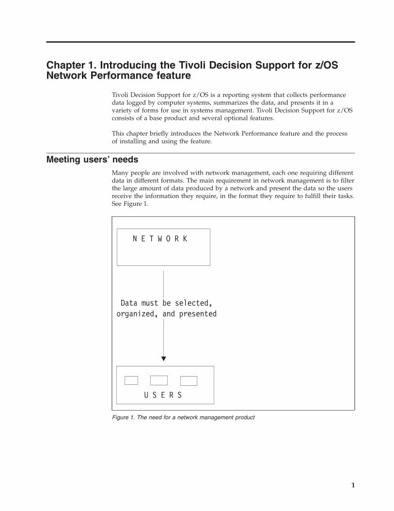
Meeting users’ needs
Many people are involved with network management, each one requiring different
data in different formats. The main requirement in network management is to filter
the large amount of data produced by a network and present the data so the users
receive the information they require, in the format they require to fulfill their tasks.
See Figure 1.
N E T W O R K
Data must be selected,organized, and presented
U S E R S
Figure 1. The need for a network management product
1
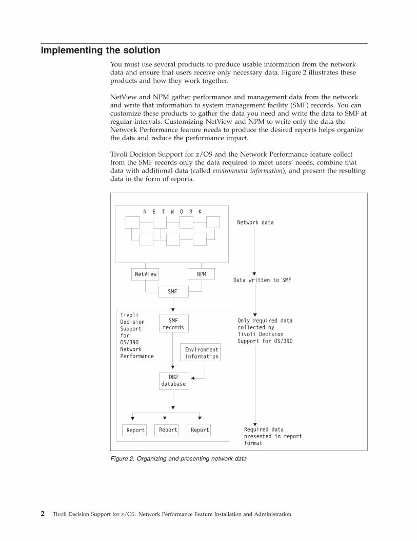
Implementing the solution
You must use several products to produce usable information from the network
data and ensure that users receive only necessary data. Figure 2 illustrates these
products and how they work together.
NetView and NPM gather performance and management data from the network
and write that information to system management facility (SMF) records. You can
customize these products to gather the data you need and write the data to SMF at
regular intervals. Customizing NetView and NPM to write only the data the
Network Performance feature needs to produce the desired reports helps organize
the data and reduce the performance impact.
Tivoli Decision Support for z/OS and the Network Performance feature collect
from the SMF records only the data required to meet users’ needs, combine that
data with additional data (called environment information), and present the resulting
data in the form of reports.
Figure 2. Organizing and presenting network data
2 Tivoli Decision Support for z/OS: Network Performance Feature Installation and Administration

The key to success when using the Network Performance feature is knowing:
v The information and resources on which you want to report and how to
customize NetView and NPM
v The way you want to organize, set objectives for, and process the data (this
information is used to define the environment data)
Chapter 1. Introduction 3
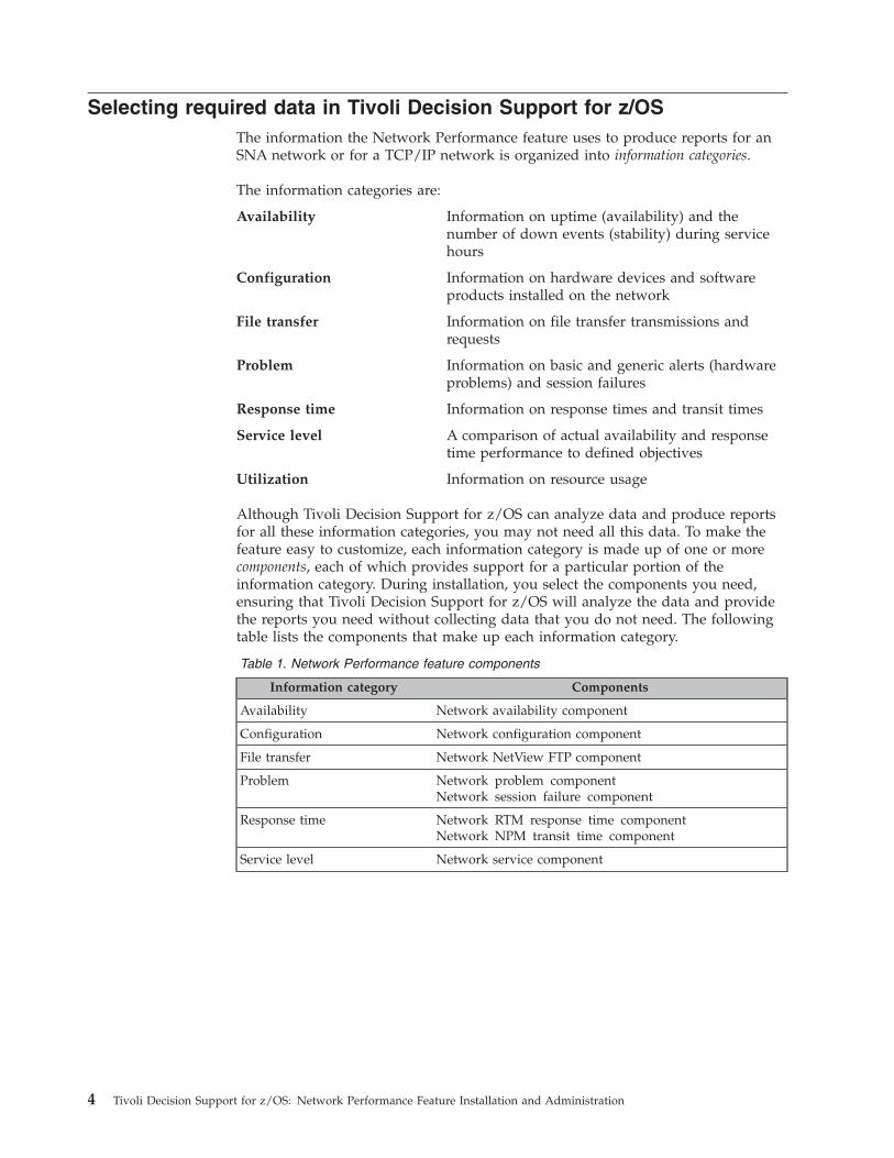
Selecting required data in Tivoli Decision Support for z/OS
The information the Network Performance feature uses to produce reports for an
SNA network or for a TCP/IP network is organized into information categories.
The information categories are:
Availability Information on uptime (availability) and the
number of down events (stability) during service
hours
Configuration Information on hardware devices and software
products installed on the network
File transfer Information on file transfer transmissions and
requests
Problem Information on basic and generic alerts (hardware
problems) and session failures
Response time Information on response times and transit times
Service level A comparison of actual availability and response
time performance to defined objectives
Utilization Information on resource usage
Although Tivoli Decision Support for z/OS can analyze data and produce reports
for all these information categories, you may not need all this data. To make the
feature easy to customize, each information category is made up of one or more
components, each of which provides support for a particular portion of the
information category. During installation, you select the components you need,
ensuring that Tivoli Decision Support for z/OS will analyze the data and provide
the reports you need without collecting data that you do not need. The following
table lists the components that make up each information category.
Table 1. Network Performance feature components
Information category Components
Availability Network availability component
Configuration Network configuration component
File transfer Network NetView FTP component
Problem Network problem component
Network session failure component
Response time Network RTM response time component
Network NPM transit time component
Service level Network service component
4 Tivoli Decision Support for z/OS: Network Performance Feature Installation and Administration
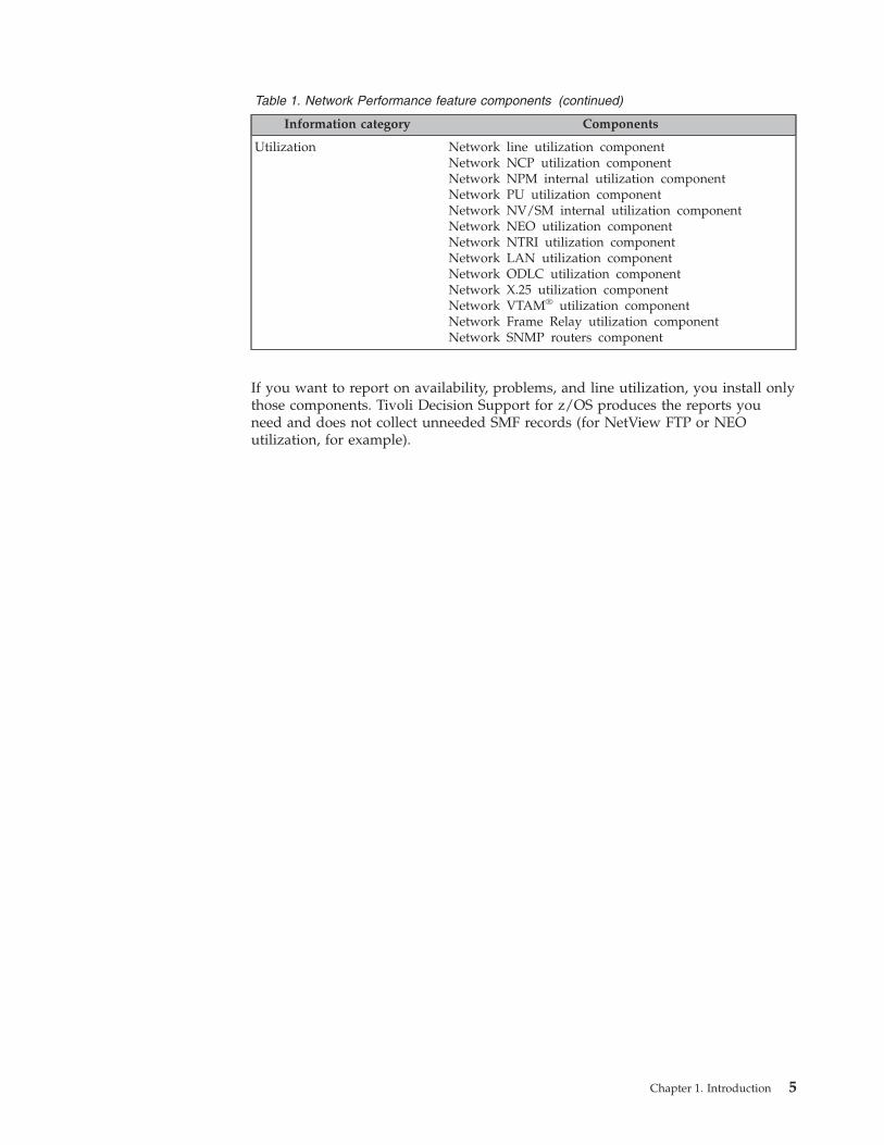
Table 1. Network Performance feature components (continued)
Information category Components
Utilization Network line utilization component
Network NCP utilization component
Network NPM internal utilization component
Network PU utilization component
Network NV/SM internal utilization component
Network NEO utilization component
Network NTRI utilization component
Network LAN utilization component
Network ODLC utilization component
Network X.25 utilization component
Network VTAM® utilization component
Network Frame Relay utilization component
Network SNMP routers component
If you want to report on availability, problems, and line utilization, you install only
those components. Tivoli Decision Support for z/OS produces the reports you
need and does not collect unneeded SMF records (for NetView FTP or NEO
utilization, for example).
Chapter 1. Introduction 5
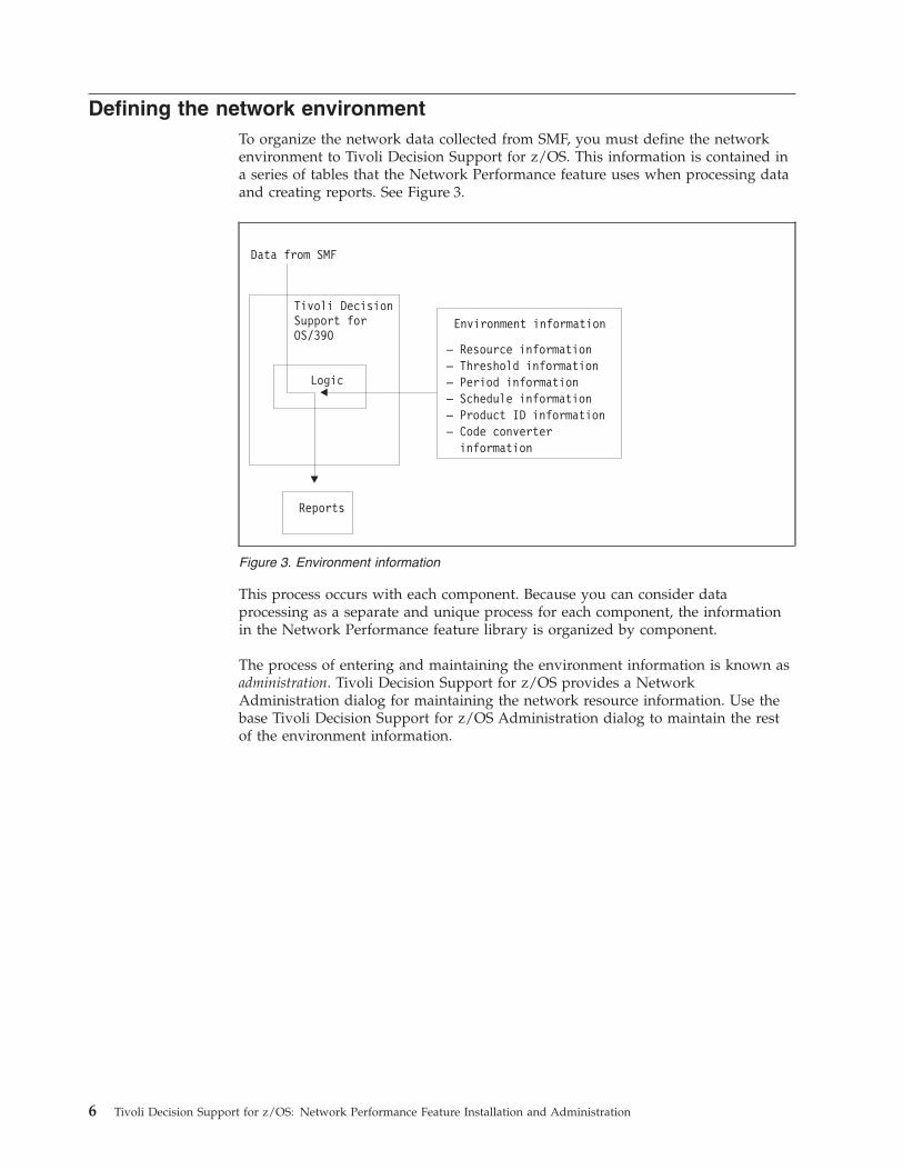
Defining the network environment
To organize the network data collected from SMF, you must define the network
environment to Tivoli Decision Support for z/OS. This information is contained in
a series of tables that the Network Performance feature uses when processing data
and creating reports. See Figure 3.
This process occurs with each component. Because you can consider data
processing as a separate and unique process for each component, the information
in the Network Performance feature library is organized by component.
The process of entering and maintaining the environment information is known as
administration. Tivoli Decision Support for z/OS provides a Network
Administration dialog for maintaining the network resource information. Use the
base Tivoli Decision Support for z/OS Administration dialog to maintain the rest
of the environment information.
Figure 3. Environment information
6 Tivoli Decision Support for z/OS: Network Performance Feature Installation and Administration
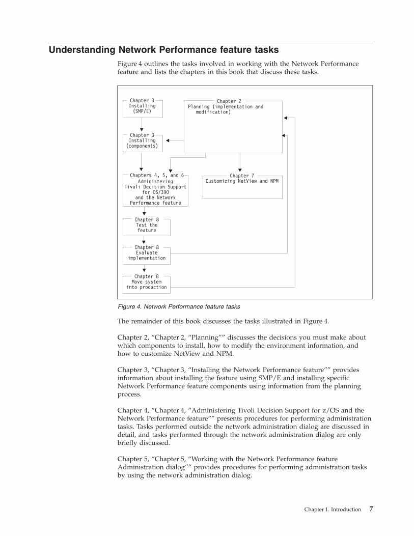
Understanding Network Performance feature tasks
Figure 4 outlines the tasks involved in working with the Network Performance
feature and lists the chapters in this book that discuss these tasks.
The remainder of this book discusses the tasks illustrated in Figure 4.
Chapter 2, “Chapter 2, “Planning”” discusses the decisions you must make about
which components to install, how to modify the environment information, and
how to customize NetView and NPM.
Chapter 3, “Chapter 3, “Installing the Network Performance feature”” provides
information about installing the feature using SMP/E and installing specific
Network Performance feature components using information from the planning
process.
Chapter 4, “Chapter 4, “Administering Tivoli Decision Support for z/OS and the
Network Performance feature”” presents procedures for performing administration
tasks. Tasks performed outside the network administration dialog are discussed in
detail, and tasks performed through the network administration dialog are only
briefly discussed.
Chapter 5, “Chapter 5, “Working with the Network Performance feature
Administration dialog”” provides procedures for performing administration tasks
by using the network administration dialog.
Figure 4. Network Performance feature tasks
Chapter 1. Introduction 7
Chapter 6, ″Chapter 6, “Administration Dialog Example”″ contains an example of
the procedures involved in using the Network administration dialog.
Chapter 7, “Chapter 7, “Customizing NetView and NPM”” presents information
about customizing NetView and NPM to support the components you have
installed.
Chapter 8, “Chapter 8, “Testing and maintaining the Network Performance
feature”” provides information about performing a test run, evaluating the success
of that run, making any necessary modifications, and moving from the test system
to an in-production system.
8 Tivoli Decision Support for z/OS: Network Performance Feature Installation and Administration
Chapter 2. Planning
This chapter provides information about the planning required to implement and
modify your Network Performance feature installation.
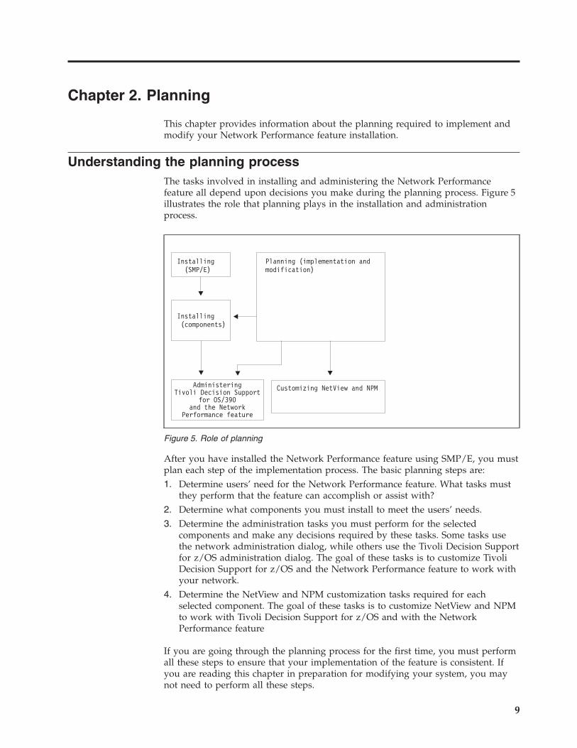
Understanding the planning process
The tasks involved in installing and administering the Network Performance
feature all depend upon decisions you make during the planning process. Figure 5
illustrates the role that planning plays in the installation and administration
process.
After you have installed the Network Performance feature using SMP/E, you must
plan each step of the implementation process. The basic planning steps are:
1. Determine users’ need for the Network Performance feature. What tasks must
they perform that the feature can accomplish or assist with?
2. Determine what components you must install to meet the users’ needs.
3. Determine the administration tasks you must perform for the selected
components and make any decisions required by these tasks. Some tasks use
the network administration dialog, while others use the Tivoli Decision Support
for z/OS administration dialog. The goal of these tasks is to customize Tivoli
Decision Support for z/OS and the Network Performance feature to work with
your network.
4. Determine the NetView and NPM customization tasks required for each
selected component. The goal of these tasks is to customize NetView and NPM
to work with Tivoli Decision Support for z/OS and with the Network
Performance feature
If you are going through the planning process for the first time, you must perform
all these steps to ensure that your implementation of the feature is consistent. If
you are reading this chapter in preparation for modifying your system, you may
not need to perform all these steps.
Figure 5. Role of planning
9
Planning for installation
The first and most critical planning task is determining what kind of information
users need from the Network Performance feature. For example, users may be
interested only in the availability of network resources or response times of
network transactions. Installing only those parts of the feature needed to meet user
requirements ensures that the feature provides maximum benefit for users while
minimizing the performance impact caused by data collection and interpretation
activities.
Information processed by the Network Performance feature is divided into seven
information categories. Each information category consists of one or more
components that actually implement the data collection and reporting functions.
During installation, you select and install the components that meet users’ needs.
Carefully consider which components to install. If you find that you need reports
from a component that you have not installed, you must install the component and
then wait several days or weeks until enough data has been collected to create
reports. However, if you install more components than you need, Tivoli Decision
Support for z/OS will collect unnecessary SMF data, which uses valuable disk
space.
The reports created by the service component are based on data collected by the
availability, RTM response time, and NPM transit time components. Although the
tables for these components are automatically installed when you install the service
component, the installation process does not fully install the components when
installing the service component. For example, you cannot collect availability data
and generate availability reports if you have only installed the service component.
To be able to collect availability data and generate availability reports, you must
install the availability component.
Selecting specific components to install lets you specify in detail what kind of
information Tivoli Decision Support for z/OS collects. For example, the utilization
information category consists of several components, each covering a specific type
of resource. However, if your network does not contain X.25 resources, you need
not install the X.25 utilization component.
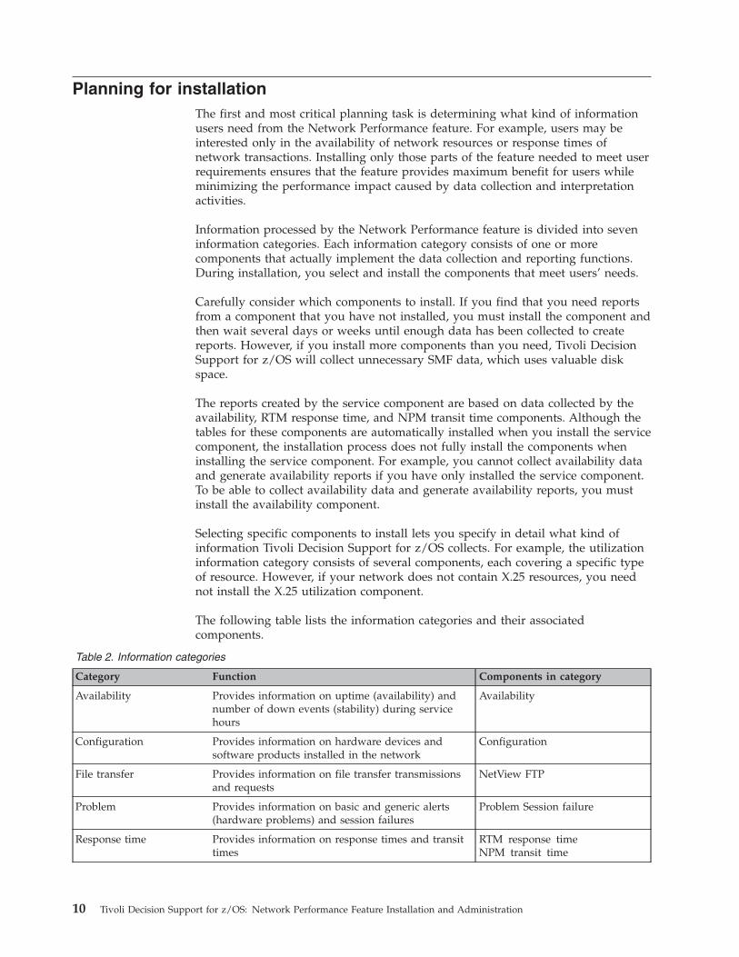
The following table lists the information categories and their associated
components.
Table 2. Information categories
Category Function Components in category
Availability Provides information on uptime (availability) and
number of down events (stability) during service
hours
Availability
Configuration Provides information on hardware devices and
software products installed in the network
Configuration
File transfer Provides information on file transfer transmissions
and requests
NetView FTP
Problem Provides information on basic and generic alerts
(hardware problems) and session failures
Problem Session failure
Response time Provides information on response times and transit
times
RTM response time
NPM transit time
10 Tivoli Decision Support for z/OS: Network Performance Feature Installation and Administration
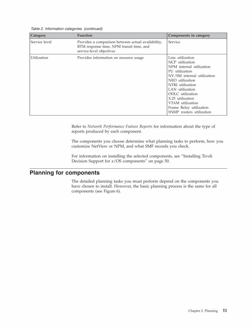
Table 2. Information categories (continued)
Category Function Components in category
Service level Provides a comparison between actual availability,
RTM response time, NPM transit time, and
service-level objectives
Service
Utilization Provides information on resource usage Line utilization
NCP utilization
NPM internal utilization
PU utilization
NV/SM internal utilization
NEO utilization
NTRI utilization
LAN utilization
ODLC utilization
X.25 utilization
VTAM utilization
Frame Relay utilization
SNMP routers utilization
Refer to Network Performance Feature Reports for information about the type of
reports produced by each component.
The components you choose determine what planning tasks to perform, how you
customize NetView or NPM, and what SMF records you check.
For information on installing the selected components, see “Installing Tivoli
Decision Support for z/OS components” on page 50.
Planning for components
The detailed planning tasks you must perform depend on the components you
have chosen to install. However, the basic planning process is the same for all
components (see Figure 6).
Chapter 2. Planning 11
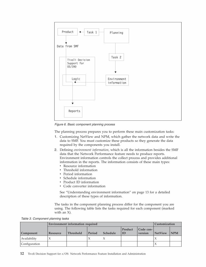
The planning process prepares you to perform these main customization tasks:
1. Customizing NetView and NPM, which gather the network data and write the
data to SMF. You must customize these products so they generate the data
required by the components you install.
2. Defining environment information, which is all the information besides the SMF
data that the Network Performance feature needs to produce reports.
Environment information controls the collect process and provides additional
information in the reports. The information consists of these main types:
v Resource information
v Threshold information
v Period information
v Schedule information
v Product ID information
v Code converter information
See “Understanding environment information” on page 13 for a detailed
description of these types of information.
The tasks in the component planning process differ for the component you are
using. The following table lists the tasks required for each component (marked
with an X).
Table 3. Component planning tasks
Component
Environment information required Customization
Resource Threshold Period Schedule
Product
ID
Code con-
version NetView NPM
Availability X X X X
Configuration X
Figure 6. Basic component planning process
12 Tivoli Decision Support for z/OS: Network Performance Feature Installation and Administration
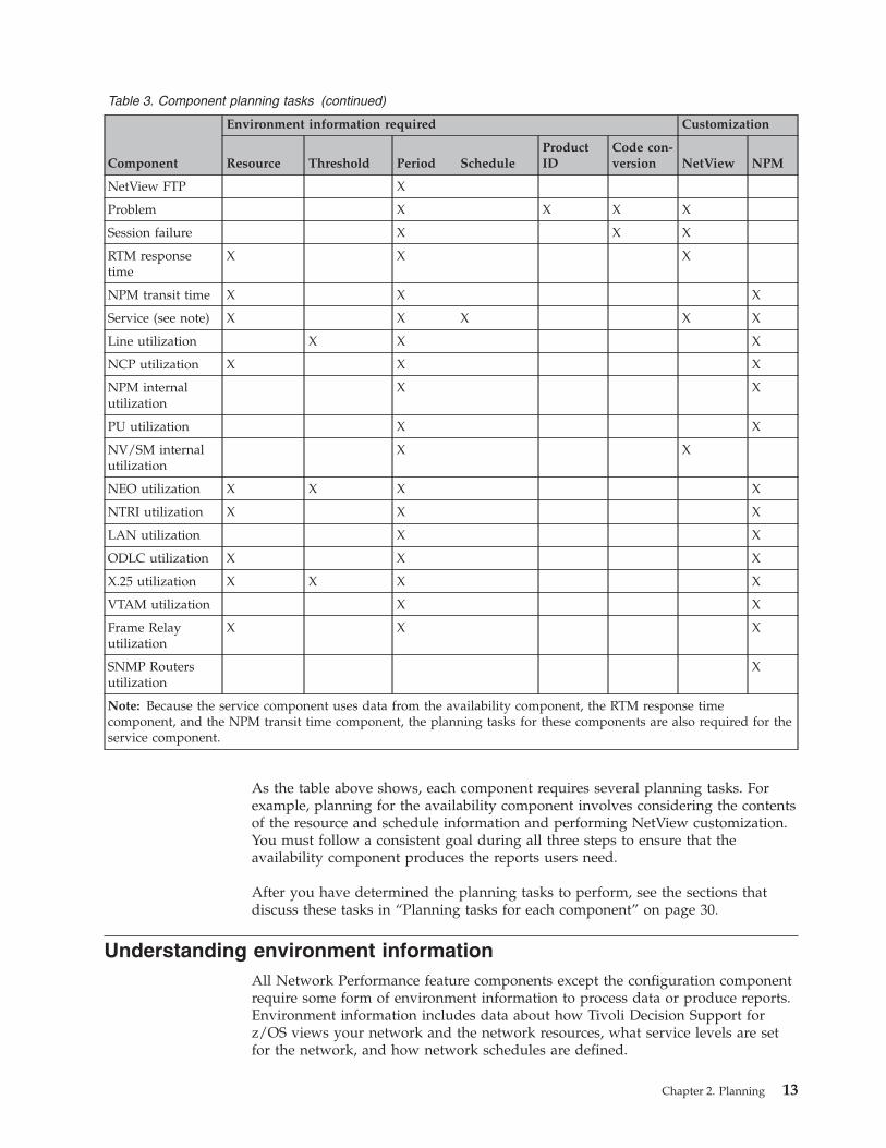
Table 3. Component planning tasks (continued)
Component
Environment information required Customization
Resource Threshold Period Schedule
Product
ID
Code con-
version NetView NPM
NetView FTP X
Problem X X X X
Session failure X X X
RTM response
time
X X X
NPM transit time X X X
Service (see note) X X X X X
Line utilization X X X
NCP utilization X X X
NPM internal
utilization
X X
PU utilization X X
NV/SM internal
utilization
X X
NEO utilization X X X X
NTRI utilization X X X
LAN utilization X X
ODLC utilization X X X
X.25 utilization X X X X
VTAM utilization X X
Frame Relay
utilization
X X X
SNMP Routers
utilization
X
Note: Because the service component uses data from the availability component, the RTM response time
component, and the NPM transit time component, the planning tasks for these components are also required for the
service component.
As the table above shows, each component requires several planning tasks. For
example, planning for the availability component involves considering the contents
of the resource and schedule information and performing NetView customization.
You must follow a consistent goal during all three steps to ensure that the
availability component produces the reports users need.
After you have determined the planning tasks to perform, see the sections that
discuss these tasks in “Planning tasks for each component” on page 30.
Understanding environment information
All Network Performance feature components except the configuration component
require some form of environment information to process data or produce reports.
Environment information includes data about how Tivoli Decision Support for
z/OS views your network and the network resources, what service levels are set
for the network, and how network schedules are defined.
Chapter 2. Planning 13
Maintaining the environment information
Tivoli Decision Support for z/OS stores most of the environment information in
lookup tables, but some (such as response-time objectives and transit time
objectives) is stored in NetView and NPM. You can maintain the information
stored in Tivoli Decision Support for z/OS lookup tables by using either of these:
v Tivoli Decision Support for z/OS administration dialog
v Network administration dialog
The dialog you use depends on the information you are modifying. The network
administration dialog is designed specifically for working with network resource
information. You use the Tivoli Decision Support for z/OS administration dialog to
modify the rest of the environment information.
During installation, Tivoli Decision Support for z/OS initializes some of the lookup
tables with default values. These lookup tables require very little maintenance.
However, you must update the tables that Tivoli Decision Support for z/OS does
not initialize for the Network Performance feature to work properly. You must also
maintain these tables as your network environment changes.
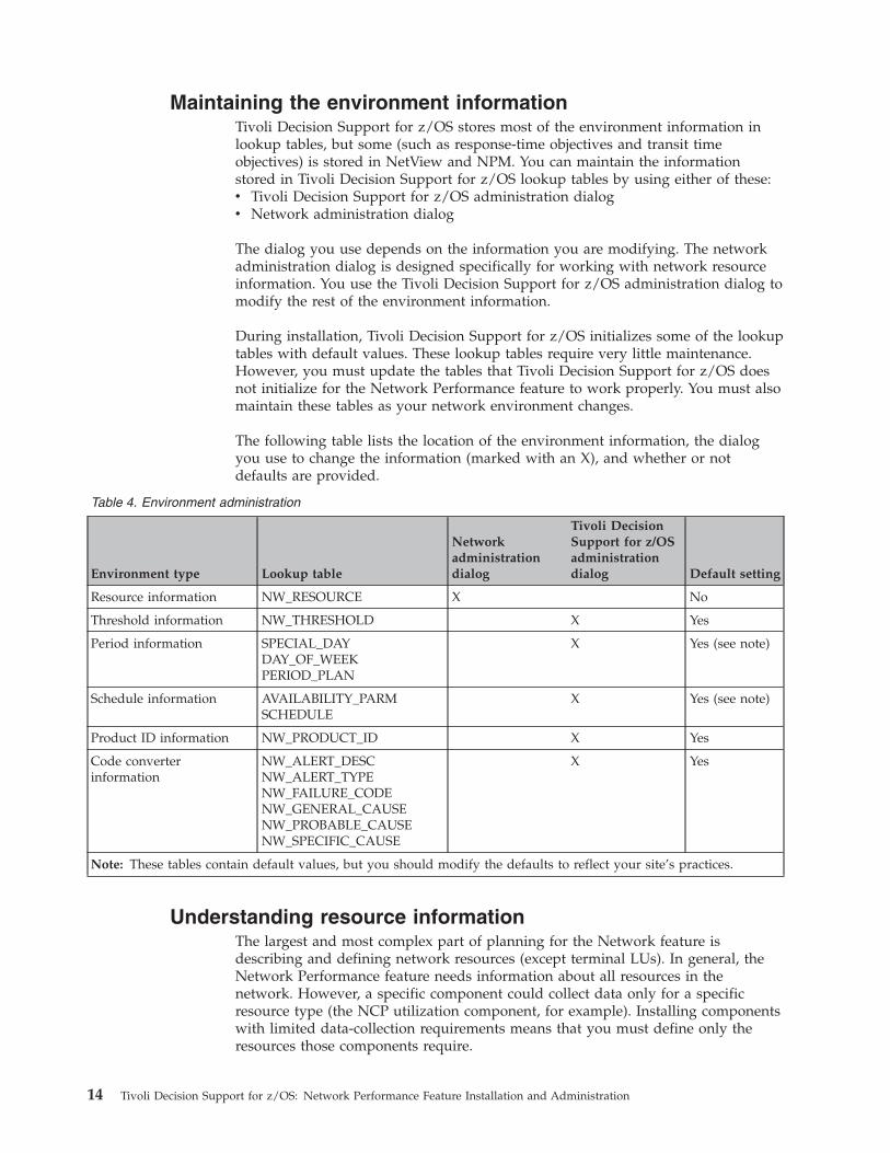
The following table lists the location of the environment information, the dialog
you use to change the information (marked with an X), and whether or not
defaults are provided.
Table 4. Environment administration
Environment type Lookup table
Network
administration
dialog
Tivoli Decision
Support for z/OS
administration
dialog Default setting
Resource information NW_RESOURCE X No
Threshold information NW_THRESHOLD X Yes
Period information SPECIAL_DAY
DAY_OF_WEEK
PERIOD_PLAN
X Yes (see note)
Schedule information AVAILABILITY_PARM
SCHEDULE
X Yes (see note)
Product ID information NW_PRODUCT_ID X Yes
Code converter
information
NW_ALERT_DESC
NW_ALERT_TYPE
NW_FAILURE_CODE
NW_GENERAL_CAUSE
NW_PROBABLE_CAUSE
NW_SPECIFIC_CAUSE
X Yes
Note: These tables contain default values, but you should modify the defaults to reflect your site’s practices.
Understanding resource information
The largest and most complex part of planning for the Network feature is
describing and defining network resources (except terminal LUs). In general, the
Network Performance feature needs information about all resources in the
network. However, a specific component could collect data only for a specific
resource type (the NCP utilization component, for example). Installing components
with limited data-collection requirements means that you must define only the
resources those components require.
14 Tivoli Decision Support for z/OS: Network Performance Feature Installation and Administration
Sources of resource data
The Network Performance feature lets you use one of these sources for resource
data:
v Data entered manually
v Data from STATMON
v Data from an external source
You can enter data manually using the network administration dialog to type
information about each network resource. However, the large amount of resource
data makes this task impractical. To avoid the need to enter resource information
manually, the dialog contains functions to let you load existing resource data from
the STATMON preprocessor or from an external source.
STATMON data includes information about the name, type, and description of a
resource. The dialog uses defaults and definition rules to provide the remaining
information. If the information provided by the defaults and rules does not meet
your requirements, you must use the network administration dialog to change the
information.
External data must follow a standard format (described in Appendix B, “External
Data File Format,” on page 171). It includes all resource information required by
the feature. If the information provided by the external source does not meet your
requirements, you must change the information at the external source, rather than
in the Network Performance feature.
You must consider these questions when planning resource information:
v How is the resource described? (See “Describing resources.”)
v How is the resource named? (See “Defining synonym names” on page 18.)
v What is the service-level objective? (See “Establishing service-level objectives” on
page 20.)
v Should this resource be included in the availability process? (See “Including
resources in availability processing” on page 19.)
v How are resources grouped? (See “Grouping resources” on page 16.)
v How are resources connected? (See “Understanding resource connections” on
page 20.)
You need not answer every question for all components. For example, if you are
installing the NCP utilization component, you need not consider whether to
include resources in the availability process.
Describing resources
You must describe each resource by using both a resource type identifier and a text
description. The description can include information such as equipment type or
location. The resource type is one of these standard types that the Network
Performance feature recognizes:
v Connection to either another domain or another network (Conn)
v Communication control unit (NCP)
v Line
v Cluster connected by a leased line (Cluster)
v Locally attached cluster (Local)
v Cluster connected as a switched resource (Switched)
v Application (Appl)
Chapter 2. Planning 15
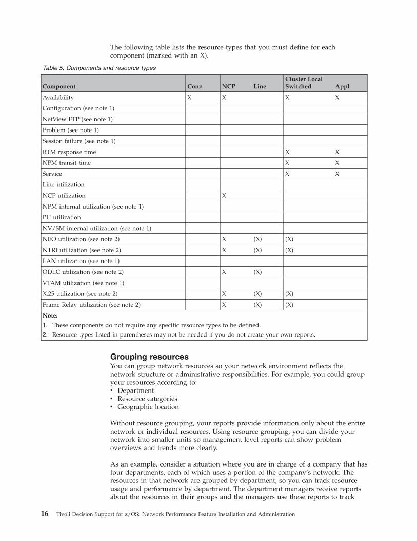
The following table lists the resource types that you must define for each
component (marked with an X).
Table 5. Components and resource types
Component Conn NCP Line
Cluster Local
Switched Appl
Availability X X X X
Configuration (see note 1)
NetView FTP (see note 1)
Problem (see note 1)
Session failure (see note 1)
RTM response time X X
NPM transit time X X
Service X X
Line utilization
NCP utilization X
NPM internal utilization (see note 1)
PU utilization
NV/SM internal utilization (see note 1)
NEO utilization (see note 2) X (X) (X)
NTRI utilization (see note 2) X (X) (X)
LAN utilization (see note 1)
ODLC utilization (see note 2) X (X)
VTAM utilization (see note 1)
X.25 utilization (see note 2) X (X) (X)
Frame Relay utilization (see note 2) X (X) (X)
Note:
1. These components do not require any specific resource types to be defined.
2. Resource types listed in parentheses may not be needed if you do not create your own reports.
Grouping resources
You can group network resources so your network environment reflects the
network structure or administrative responsibilities. For example, you could group
your resources according to:
v Department
v Resource categories
v Geographic location
Without resource grouping, your reports provide information only about the entire
network or individual resources. Using resource grouping, you can divide your
network into smaller units so management-level reports can show problem
overviews and trends more clearly.
As an example, consider a situation where you are in charge of a company that has
four departments, each of which uses a portion of the company’s network. The
resources in that network are grouped by department, so you can track resource
usage and performance by department. The department managers receive reports
about the resources in their groups and the managers use these reports to track
16 Tivoli Decision Support for z/OS: Network Performance Feature Installation and Administration
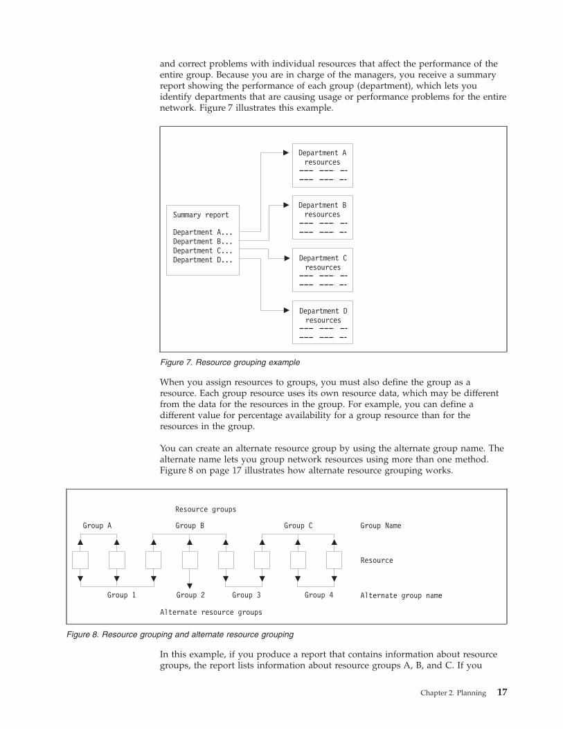
and correct problems with individual resources that affect the performance of the
entire group. Because you are in charge of the managers, you receive a summary
report showing the performance of each group (department), which lets you
identify departments that are causing usage or performance problems for the entire
network. Figure 7 illustrates this example.
When you assign resources to groups, you must also define the group as a
resource. Each group resource uses its own resource data, which may be different
from the data for the resources in the group. For example, you can define a
different value for percentage availability for a group resource than for the
resources in the group.
You can create an alternate resource group by using the alternate group name. The
alternate name lets you group network resources using more than one method.
Figure 8 on page 17 illustrates how alternate resource grouping works.
In this example, if you produce a report that contains information about resource
groups, the report lists information about resource groups A, B, and C. If you
Summary report
Department A...Department B...Department C...Department D...
Department Aresources
Department Bresources
Department Cresources
Department Dresources
Figure 7. Resource grouping example
Figure 8. Resource grouping and alternate resource grouping
Chapter 2. Planning 17
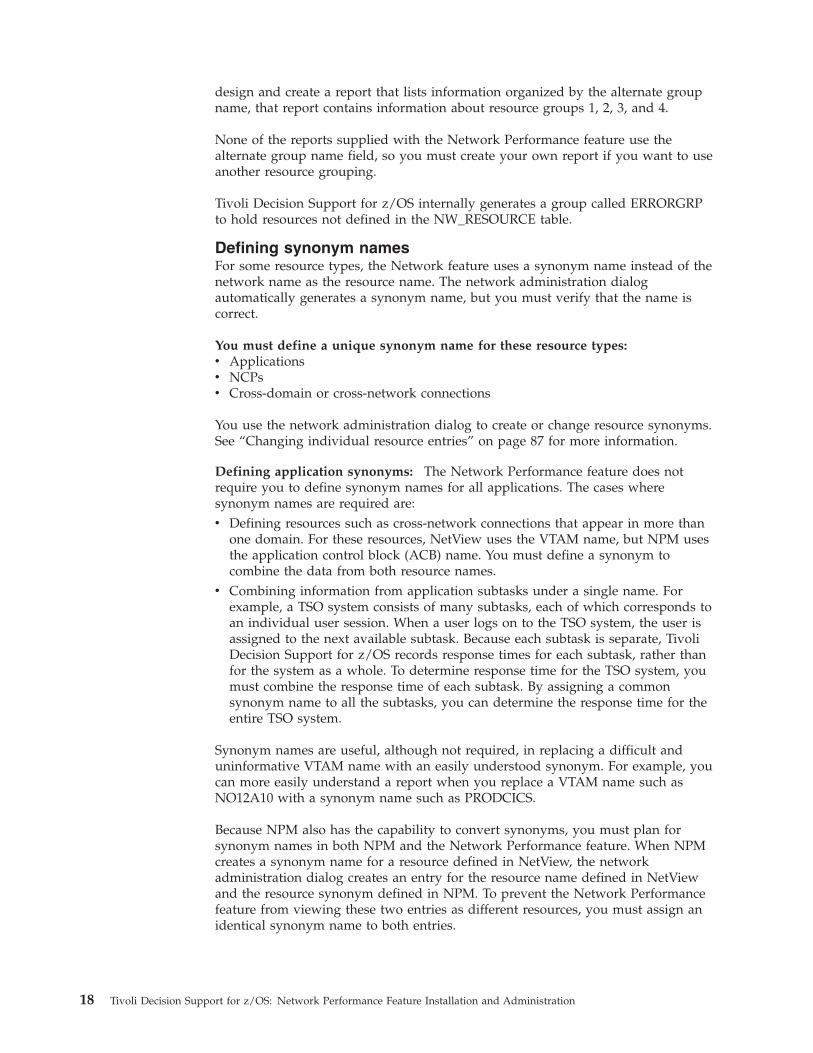
design and create a report that lists information organized by the alternate group
name, that report contains information about resource groups 1, 2, 3, and 4.
None of the reports supplied with the Network Performance feature use the
alternate group name field, so you must create your own report if you want to use
another resource grouping.
Tivoli Decision Support for z/OS internally generates a group called ERRORGRP
to hold resources not defined in the NW_RESOURCE table.
Defining synonym names
For some resource types, the Network feature uses a synonym name instead of the
network name as the resource name. The network administration dialog
automatically generates a synonym name, but you must verify that the name is
correct.
You must define a unique synonym name for these resource types:
v Applications
v NCPs
v Cross-domain or cross-network connections
You use the network administration dialog to create or change resource synonyms.
See “Changing individual resource entries” on page 87 for more information.
Defining application synonyms: The Network Performance feature does not
require you to define synonym names for all applications. The cases where
synonym names are required are:
v Defining resources such as cross-network connections that appear in more than
one domain. For these resources, NetView uses the VTAM name, but NPM uses
the application control block (ACB) name. You must define a synonym to
combine the data from both resource names.
v Combining information from application subtasks under a single name. For
example, a TSO system consists of many subtasks, each of which corresponds to
an individual user session. When a user logs on to the TSO system, the user is
assigned to the next available subtask. Because each subtask is separate, Tivoli
Decision Support for z/OS records response times for each subtask, rather than
for the system as a whole. To determine response time for the TSO system, you
must combine the response time of each subtask. By assigning a common
synonym name to all the subtasks, you can determine the response time for the
entire TSO system.
Synonym names are useful, although not required, in replacing a difficult and
uninformative VTAM name with an easily understood synonym. For example, you
can more easily understand a report when you replace a VTAM name such as
NO12A10 with a synonym name such as PRODCICS.
Because NPM also has the capability to convert synonyms, you must plan for
synonym names in both NPM and the Network Performance feature. When NPM
creates a synonym name for a resource defined in NetView, the network
administration dialog creates an entry for the resource name defined in NetView
and the resource synonym defined in NPM. To prevent the Network Performance
feature from viewing these two entries as different resources, you must assign an
identical synonym name to both entries.
18 Tivoli Decision Support for z/OS: Network Performance Feature Installation and Administration
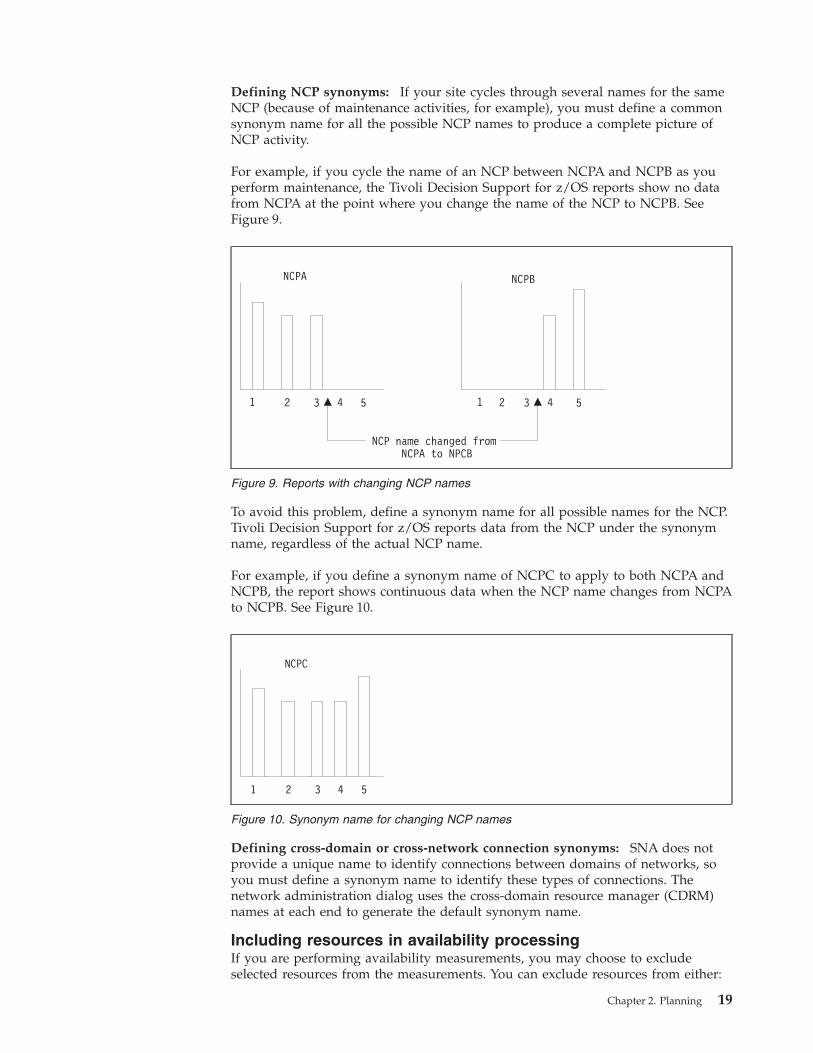
Defining NCP synonyms: If your site cycles through several names for the same
NCP (because of maintenance activities, for example), you must define a common
synonym name for all the possible NCP names to produce a complete picture of
NCP activity.
For example, if you cycle the name of an NCP between NCPA and NCPB as you
perform maintenance, the Tivoli Decision Support for z/OS reports show no data
from NCPA at the point where you change the name of the NCP to NCPB. See
Figure 9.
To avoid this problem, define a synonym name for all possible names for the NCP.
Tivoli Decision Support for z/OS reports data from the NCP under the synonym
name, regardless of the actual NCP name.
For example, if you define a synonym name of NCPC to apply to both NCPA and
NCPB, the report shows continuous data when the NCP name changes from NCPA
to NCPB. See Figure 10.
Defining cross-domain or cross-network connection synonyms: SNA does not
provide a unique name to identify connections between domains of networks, so
you must define a synonym name to identify these types of connections. The
network administration dialog uses the cross-domain resource manager (CDRM)
names at each end to generate the default synonym name.
Including resources in availability processing
If you are performing availability measurements, you may choose to exclude
selected resources from the measurements. You can exclude resources from either:
Figure 9. Reports with changing NCP names
NCPC
1 2 3 4 5
Figure 10. Synonym name for changing NCP names
Chapter 2. Planning 19
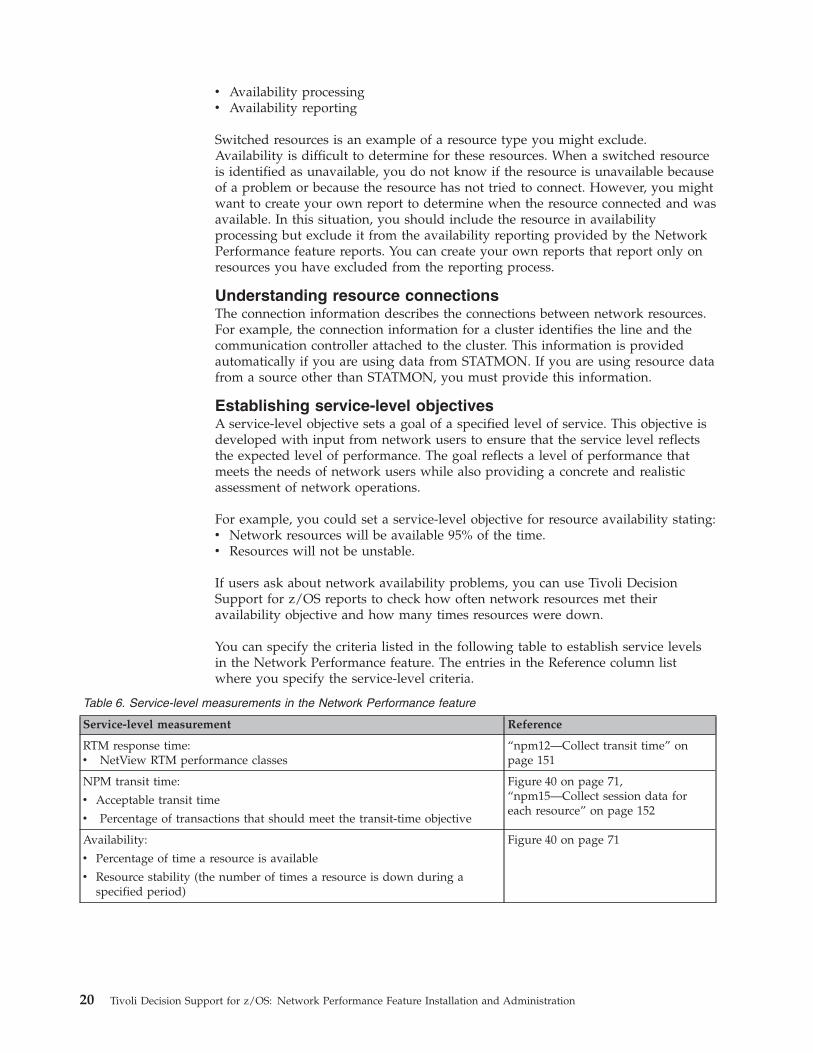
v Availability processing
v Availability reporting
Switched resources is an example of a resource type you might exclude.
Availability is difficult to determine for these resources. When a switched resource
is identified as unavailable, you do not know if the resource is unavailable because
of a problem or because the resource has not tried to connect. However, you might
want to create your own report to determine when the resource connected and was
available. In this situation, you should include the resource in availability
processing but exclude it from the availability reporting provided by the Network
Performance feature reports. You can create your own reports that report only on
resources you have excluded from the reporting process.
Understanding resource connections
The connection information describes the connections between network resources.
For example, the connection information for a cluster identifies the line and the
communication controller attached to the cluster. This information is provided
automatically if you are using data from STATMON. If you are using resource data
from a source other than STATMON, you must provide this information.
Establishing service-level objectives
A service-level objective sets a goal of a specified level of service. This objective is
developed with input from network users to ensure that the service level reflects
the expected level of performance. The goal reflects a level of performance that
meets the needs of network users while also providing a concrete and realistic
assessment of network operations.
For example, you could set a service-level objective for resource availability stating:
v Network resources will be available 95% of the time.
v Resources will not be unstable.
If users ask about network availability problems, you can use Tivoli Decision
Support for z/OS reports to check how often network resources met their
availability objective and how many times resources were down.
You can specify the criteria listed in the following table to establish service levels
in the Network Performance feature. The entries in the Reference column list
where you specify the service-level criteria.
Table 6. Service-level measurements in the Network Performance feature
Service-level measurement Reference
RTM response time:
v NetView RTM performance classes
“npm12—Collect transit time” on
page 151
NPM transit time:
v Acceptable transit time
v Percentage of transactions that should meet the transit-time objective
Figure 40 on page 71,
“npm15—Collect session data for
each resource” on page 152
Availability:
v Percentage of time a resource is available
v Resource stability (the number of times a resource is down during a
specified period)
Figure 40 on page 71
20 Tivoli Decision Support for z/OS: Network Performance Feature Installation and Administration
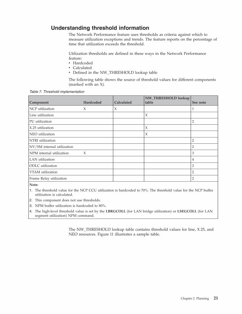
Understanding threshold information
The Network Performance feature uses thresholds as criteria against which to
measure utilization exceptions and trends. The feature reports on the percentage of
time that utilization exceeds the threshold.
Utilization thresholds are defined in these ways in the Network Performance
feature:
v Hardcoded
v Calculated
v Defined in the NW_THRESHOLD lookup table
The following table shows the source of threshold values for different components
(marked with an X).
Table 7. Threshold implementation
Component Hardcoded Calculated
NW_THRESHOLD lookup
table See note
NCP utilization X X 1
Line utilization X
PU utilization 2
X.25 utilization X
NEO utilization X
NTRI utilization 2
NV/SM internal utilization 2
NPM internal utilization X 3
LAN utilization 4
ODLC utilization 2
VTAM utilization 2
Frame Relay utilization 2
Note:
1. The threshold value for the NCP CCU utilization is hardcoded to 70%. The threshold value for the NCP buffer
utilization is calculated.
2. This component does not use thresholds.
3. NPM buffer utilization is hardcoded to 80%.
4. The high-level threshold value is set by the LBRGCOLL (for LAN bridge utilization) or LSEGCOLL (for LAN
segment utilization) NPM command.
The NW_THRESHOLD lookup table contains threshold values for line, X.25, and
NEO resources. Figure 11 illustrates a sample table.
Chapter 2. Planning 21
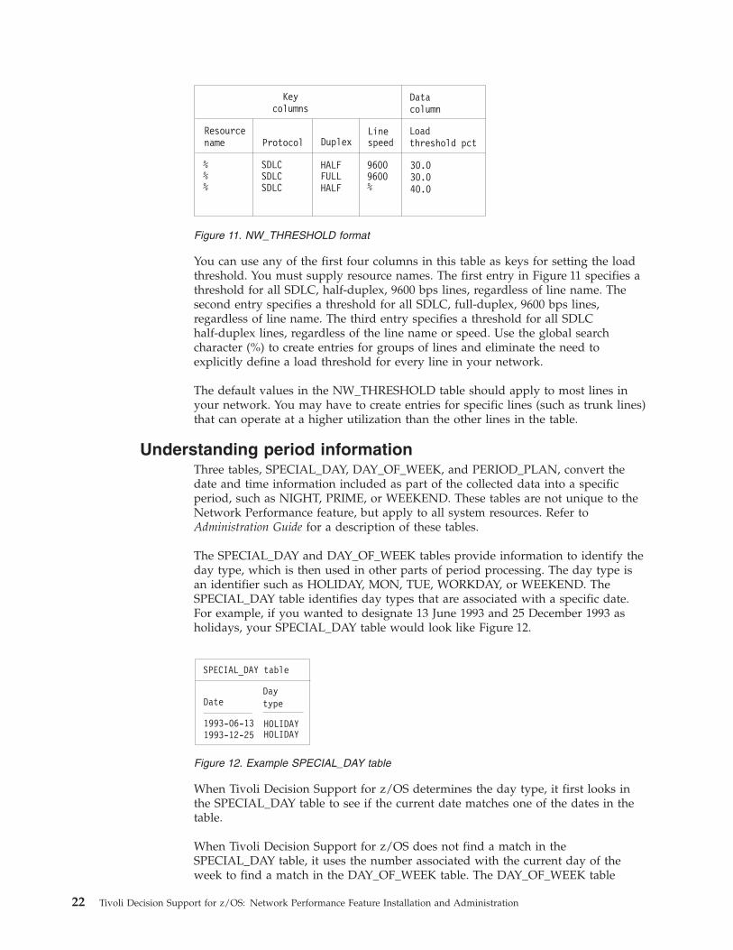
You can use any of the first four columns in this table as keys for setting the load
threshold. You must supply resource names. The first entry in Figure 11 specifies a
threshold for all SDLC, half-duplex, 9600 bps lines, regardless of line name. The
second entry specifies a threshold for all SDLC, full-duplex, 9600 bps lines,
regardless of line name. The third entry specifies a threshold for all SDLC
half-duplex lines, regardless of the line name or speed. Use the global search
character (%) to create entries for groups of lines and eliminate the need to
explicitly define a load threshold for every line in your network.
The default values in the NW_THRESHOLD table should apply to most lines in
your network. You may have to create entries for specific lines (such as trunk lines)
that can operate at a higher utilization than the other lines in the table.
Understanding period information
Three tables, SPECIAL_DAY, DAY_OF_WEEK, and PERIOD_PLAN, convert the
date and time information included as part of the collected data into a specific
period, such as NIGHT, PRIME, or WEEKEND. These tables are not unique to the
Network Performance feature, but apply to all system resources. Refer to
Administration Guide for a description of these tables.
The SPECIAL_DAY and DAY_OF_WEEK tables provide information to identify the
day type, which is then used in other parts of period processing. The day type is
an identifier such as HOLIDAY, MON, TUE, WORKDAY, or WEEKEND. The
SPECIAL_DAY table identifies day types that are associated with a specific date.
For example, if you wanted to designate 13 June 1993 and 25 December 1993 as
holidays, your SPECIAL_DAY table would look like Figure 12.
When Tivoli Decision Support for z/OS determines the day type, it first looks in
the SPECIAL_DAY table to see if the current date matches one of the dates in the
table.
When Tivoli Decision Support for z/OS does not find a match in the
SPECIAL_DAY table, it uses the number associated with the current day of the
week to find a match in the DAY_OF_WEEK table. The DAY_OF_WEEK table
Resourcename Protocol Duplex
Linespeed
Loadthreshold pct
Datacolumn
Keycolumns
%%% %
SDLC HALF 96009600FULL
HALFSDLCSDLC
30.030.040.0
Figure 11. NW_THRESHOLD format
Figure 12. Example SPECIAL_DAY table
22 Tivoli Decision Support for z/OS: Network Performance Feature Installation and Administration
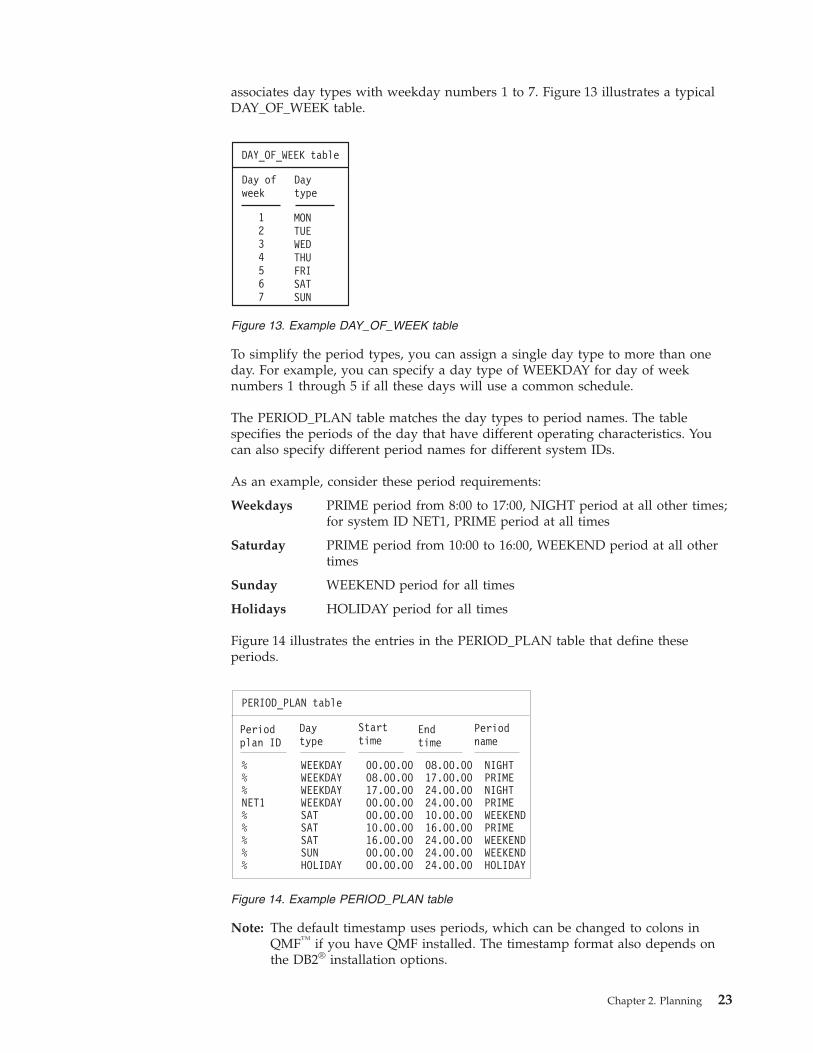
associates day types with weekday numbers 1 to 7. Figure 13 illustrates a typical
DAY_OF_WEEK table.
To simplify the period types, you can assign a single day type to more than one
day. For example, you can specify a day type of WEEKDAY for day of week
numbers 1 through 5 if all these days will use a common schedule.
The PERIOD_PLAN table matches the day types to period names. The table
specifies the periods of the day that have different operating characteristics. You
can also specify different period names for different system IDs.
As an example, consider these period requirements:
Weekdays PRIME period from 8:00 to 17:00, NIGHT period at all other times;
for system ID NET1, PRIME period at all times
Saturday PRIME period from 10:00 to 16:00, WEEKEND period at all other
times
Sunday WEEKEND period for all times
Holidays HOLIDAY period for all times
Figure 14 illustrates the entries in the PERIOD_PLAN table that define these
periods.
Note: The default timestamp uses periods, which can be changed to colons in
QMF™ if you have QMF installed. The timestamp format also depends on
the DB2® installation options.
DAY_OF_WEEK table
Day ofweek
Daytype
1234567
MONTUEWEDTHUFRISATSUN
Figure 13. Example DAY_OF_WEEK table
Figure 14. Example PERIOD_PLAN table
Chapter 2. Planning 23
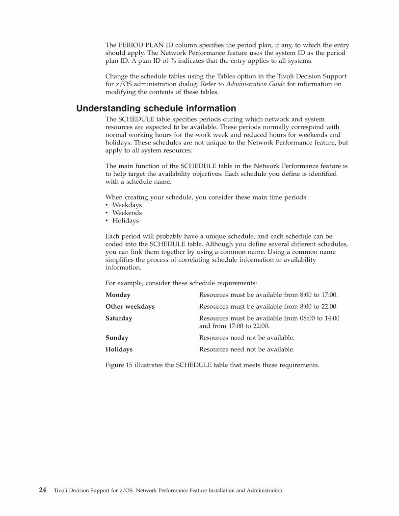
The PERIOD PLAN ID column specifies the period plan, if any, to which the entry
should apply. The Network Performance feature uses the system ID as the period
plan ID. A plan ID of % indicates that the entry applies to all systems.
Change the schedule tables using the Tables option in the Tivoli Decision Support
for z/OS administration dialog. Refer to Administration Guide for information on
modifying the contents of these tables.
Understanding schedule information
The SCHEDULE table specifies periods during which network and system
resources are expected to be available. These periods normally correspond with
normal working hours for the work week and reduced hours for weekends and
holidays. These schedules are not unique to the Network Performance feature, but
apply to all system resources.
The main function of the SCHEDULE table in the Network Performance feature is
to help target the availability objectives. Each schedule you define is identified
with a schedule name.
When creating your schedule, you consider these main time periods:
v Weekdays
v Weekends
v Holidays
Each period will probably have a unique schedule, and each schedule can be
coded into the SCHEDULE table. Although you define several different schedules,
you can link them together by using a common name. Using a common name
simplifies the process of correlating schedule information to availability
information.
For example, consider these schedule requirements:
Monday Resources must be available from 8:00 to 17:00.
Other weekdays Resources must be available from 8:00 to 22:00.
Saturday Resources must be available from 08:00 to 14:00
and from 17:00 to 22:00.
Sunday Resources need not be available.
Holidays Resources need not be available.
Figure 15 illustrates the SCHEDULE table that meets these requirements.
24 Tivoli Decision Support for z/OS: Network Performance Feature Installation and Administration
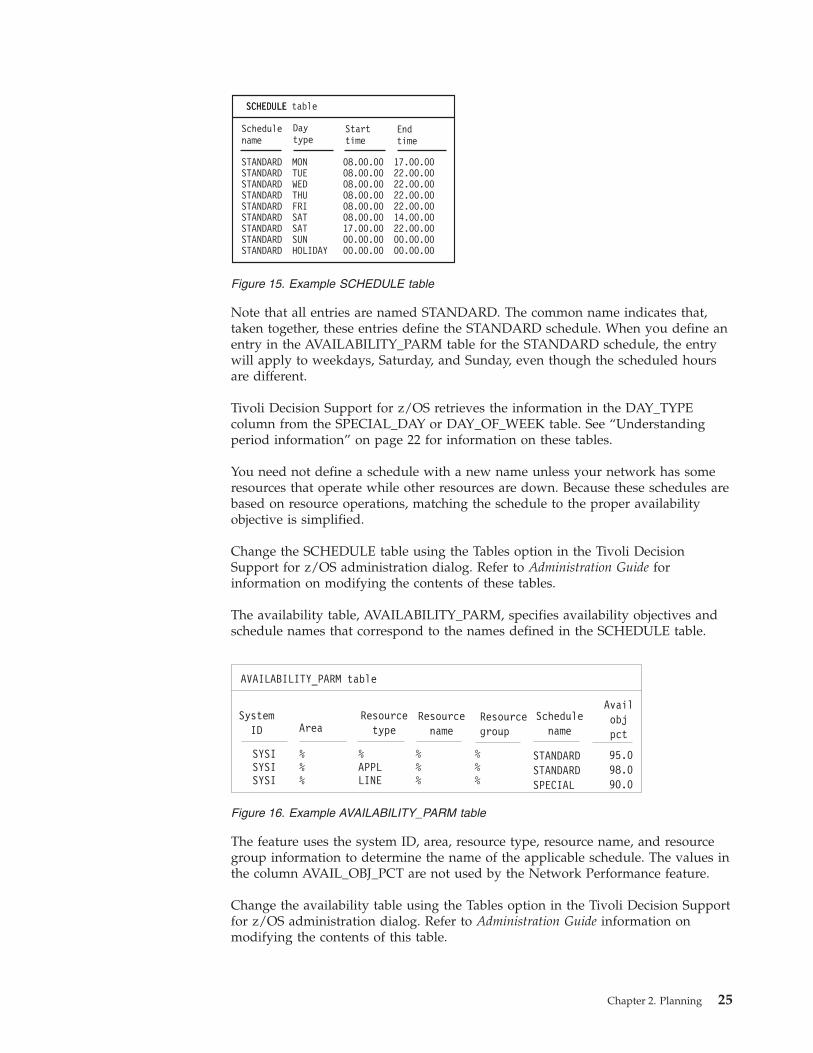
Note that all entries are named STANDARD. The common name indicates that,
taken together, these entries define the STANDARD schedule. When you define an
entry in the AVAILABILITY_PARM table for the STANDARD schedule, the entry
will apply to weekdays, Saturday, and Sunday, even though the scheduled hours
are different.
Tivoli Decision Support for z/OS retrieves the information in the DAY_TYPE
column from the SPECIAL_DAY or DAY_OF_WEEK table. See “Understanding
period information” on page 22 for information on these tables.
You need not define a schedule with a new name unless your network has some
resources that operate while other resources are down. Because these schedules are
based on resource operations, matching the schedule to the proper availability
objective is simplified.
Change the SCHEDULE table using the Tables option in the Tivoli Decision
Support for z/OS administration dialog. Refer to Administration Guide for
information on modifying the contents of these tables.
The availability table, AVAILABILITY_PARM, specifies availability objectives and
schedule names that correspond to the names defined in the SCHEDULE table.
The feature uses the system ID, area, resource type, resource name, and resource
group information to determine the name of the applicable schedule. The values in
the column AVAIL_OBJ_PCT are not used by the Network Performance feature.
Change the availability table using the Tables option in the Tivoli Decision Support
for z/OS administration dialog. Refer to Administration Guide information on
modifying the contents of this table.
SCHEDULESCHEDULE table
Schedulename
Daytype
Starttime
Endtime
STANDARD MON 08.00.00 17.00.00STANDARD TUE 08.00.00 22.00.00STANDARD WED 08.00.00 22.00.00STANDARD THU 08.00.00 22.00.00STANDARD FRI 08.00.00 22.00.00STANDARD SAT 08.00.00 14.00.00STANDARD SAT 17.00.00 22.00.00STANDARD SUN 00.00.00 00.00.00STANDARD HOLIDAY 00.00.00 00.00.00
Figure 15. Example SCHEDULE table
Figure 16. Example AVAILABILITY_PARM table
Chapter 2. Planning 25
Understanding product ID information
When the Network Performance feature processes problem data, it performs these
tasks:
v Converts the hexadecimal product ID or block ID supplied in the SMF record to
a more easily understood product name.
v Categorizes products into groups reflecting responsibilities for network products.
You can then create problem reports based on resource categories so individuals
receive reports on only those products for which they are responsible.
v Determines the hierarchy level from which information about the owning
resource should be obtained.
To accomplish this task, the feature looks up the product ID or block ID in the
NW_PRODUCT_ID table, which lists product names, resource types, and hierarchy
information for each possible identifier. The feature then uses the information from
the table when updating the NW_ALERT_BASIC_H and NW_ALERT_GENERIC_H
tables.
Although this table contains a set of default values, you may want to change the
supplied values or add new values for new products not included in the table. The
problem report NWPROBLEM18 lists the product IDs for which Tivoli Decision
Support for z/OS cannot find a corresponding name. If you modify the table, you
must include this information in each entry:
Product ID
The product ID (for generic alerts) or block ID (for basic alerts) from the
SMF record.
Product name
This field usually contains the model number (3270, 3614), model name
(SERIES/1, SYSTEM/38), or program name (NRF) represented by the
product ID or the block ID.
Resource type
The resource category (default values are APPL, CTRL, HOST, or COMM).
Hierarchy
The level of the owning resource in the network hierarchy. Each SMF
record contains configuration information for a failing network resource.
The configuration information consists of five levels of network hierarchy,
with each level represented by a resource level name and a resource level
type. The hierarchy field in the NW_PRODUCT_ID table specifies which of
these levels contains the name of the owning resource. For example, if the
hierarchy field is set to 3, the resource specified at level 3 in the hierarchy
is considered the owning resource.
A resource connected to the host (except communication controllers)
should specify the host as level 3 in the hierarchy. A resource connected to
a communication controller should specify the communication controller as
level 3. A resource that controls another network (such as AS/400) should
specify its own name as level 1.
Figure 17 illustrates a sample NW_PRODUCT_ID table.
26 Tivoli Decision Support for z/OS: Network Performance Feature Installation and Administration
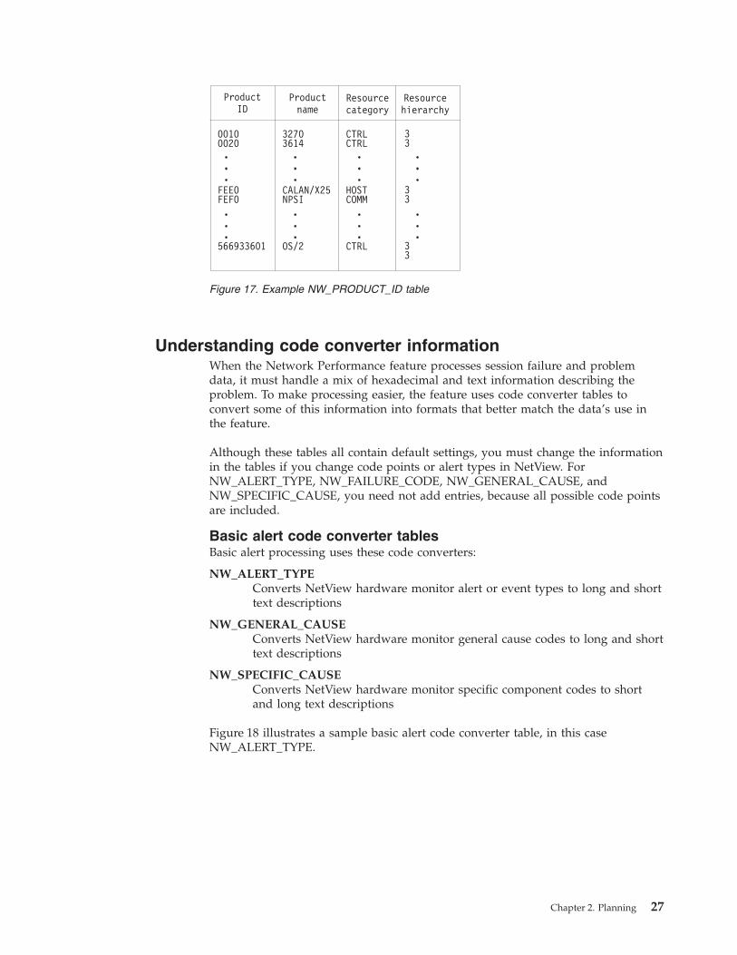
Understanding code converter information
When the Network Performance feature processes session failure and problem
data, it must handle a mix of hexadecimal and text information describing the
problem. To make processing easier, the feature uses code converter tables to
convert some of this information into formats that better match the data’s use in
the feature.
Although these tables all contain default settings, you must change the information
in the tables if you change code points or alert types in NetView. For
NW_ALERT_TYPE, NW_FAILURE_CODE, NW_GENERAL_CAUSE, and
NW_SPECIFIC_CAUSE, you need not add entries, because all possible code points
are included.
Basic alert code converter tables
Basic alert processing uses these code converters:
NW_ALERT_TYPE
Converts NetView hardware monitor alert or event types to long and short
text descriptions
NW_GENERAL_CAUSE
Converts NetView hardware monitor general cause codes to long and short
text descriptions
NW_SPECIFIC_CAUSE
Converts NetView hardware monitor specific component codes to short
and long text descriptions
Figure 18 illustrates a sample basic alert code converter table, in this case
NW_ALERT_TYPE.
Figure 17. Example NW_PRODUCT_ID table
Chapter 2. Planning 27
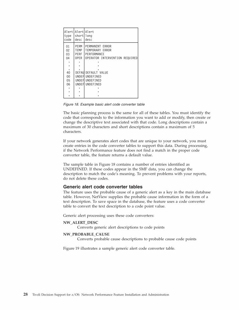
The basic planning process is the same for all of these tables. You must identify the
code that corresponds to the information you want to add or modify, then create or
change the descriptive text associated with that code. Long descriptions contain a
maximum of 30 characters and short descriptions contain a maximum of 5
characters.
If your network generates alert codes that are unique to your network, you must
create entries in the code converter tables to support this data. During processing,
if the Network Performance feature does not find a match in the proper code
converter table, the feature returns a default value.
The sample table in Figure 18 contains a number of entries identified as
UNDEFINED. If these codes appear in the SMF data, you can change the
description to match the code’s meaning. To prevent problems with your reports,
do not delete these codes.
Generic alert code converter tables
The feature uses the probable cause of a generic alert as a key in the main database
table. However, NetView supplies the probable cause information in the form of a
text description. To save space in the database, the feature uses a code converter
table to convert the text description to a code point value.
Generic alert processing uses these code converters:
NW_ALERT_DESC
Converts generic alert descriptions to code points
NW_PROBABLE_CAUSE
Converts probable cause descriptions to probable cause code points
Figure 19 illustrates a sample generic alert code converter table.
Figure 18. Example basic alert code converter table
28 Tivoli Decision Support for z/OS: Network Performance Feature Installation and Administration
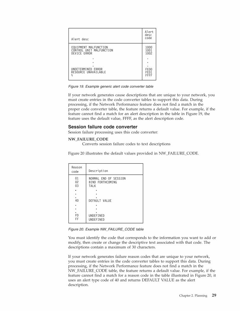
If your network generates cause descriptions that are unique to your network, you
must create entries in the code converter tables to support this data. During
processing, if the Network Performance feature does not find a match in the
proper code converter table, the feature returns a default value. For example, if the
feature cannot find a match for an alert description in the table in Figure 19, the
feature uses the default value, FFFF, as the alert description code.
Session failure code converter
Session failure processing uses this code converter:
NW_FAILURE_CODE
Converts session failure codes to text descriptions
Figure 20 illustrates the default values provided in NW_FAILURE_CODE.
You must identify the code that corresponds to the information you want to add or
modify, then create or change the descriptive text associated with that code. The
descriptions contain a maximum of 30 characters.
If your network generates failure reason codes that are unique to your network,
you must create entries in the code converter tables to support this data. During
processing, if the Network Performance feature does not find a match in the
NW_FAILURE_CODE table, the feature returns a default value. For example, if the
feature cannot find a match for a reason code in the table illustrated in Figure 20, it
uses an alert type code of 40 and returns DEFAULT VALUE as the alert
description.
Figure 19. Example generic alert code converter table
Figure 20. Example NW_FAILURE_CODE table
Chapter 2. Planning 29
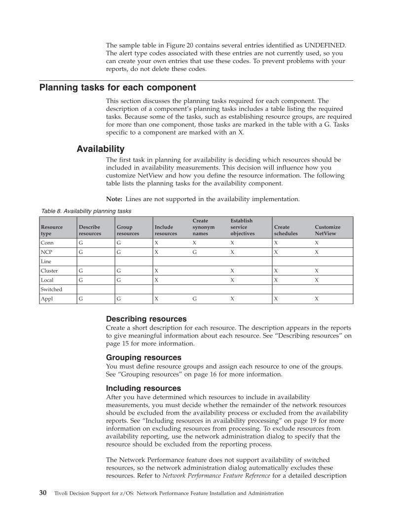
The sample table in Figure 20 contains several entries identified as UNDEFINED.
The alert type codes associated with these entries are not currently used, so you
can create your own entries that use these codes. To prevent problems with your
reports, do not delete these codes.
Planning tasks for each component
This section discusses the planning tasks required for each component. The
description of a component’s planning tasks includes a table listing the required
tasks. Because some of the tasks, such as establishing resource groups, are required
for more than one component, those tasks are marked in the table with a G. Tasks
specific to a component are marked with an X.
Availability
The first task in planning for availability is deciding which resources should be
included in availability measurements. This decision will influence how you
customize NetView and how you define the resource information. The following
table lists the planning tasks for the availability component.
Note: Lines are not supported in the availability implementation.
Table 8. Availability planning tasks
Resource
type
Describe
resources
Group
resources
Include
resources
Create
synonym
names
Establish
service
objectives
Create
schedules
Customize
NetView
Conn G G X X X X X
NCP G G X G X X X
Line
Cluster G G X X X X
Local G G X X X X
Switched
Appl G G X G X X X
Describing resources
Create a short description for each resource. The description appears in the reports
to give meaningful information about each resource. See “Describing resources” on
page 15 for more information.
Grouping resources
You must define resource groups and assign each resource to one of the groups.
See “Grouping resources” on page 16 for more information.
Including resources
After you have determined which resources to include in availability
measurements, you must decide whether the remainder of the network resources
should be excluded from the availability process or excluded from the availability
reports. See “Including resources in availability processing” on page 19 for more
information on excluding resources from processing. To exclude resources from
availability reporting, use the network administration dialog to specify that the
resource should be excluded from the reporting process.
The Network Performance feature does not support availability of switched
resources, so the network administration dialog automatically excludes these
resources. Refer to Network Performance Feature Reference for a detailed description
30 Tivoli Decision Support for z/OS: Network Performance Feature Installation and Administration
of the problems involved in including switched resources in the availability
process. If you decide to include switched resources, perform the same tasks that
you perform for cluster and local resources.
Creating synonym names
You must create a synonym name for application, NCP, and cross-domain or
cross-network connection resources. See “Defining synonym names” on page 18 for
special considerations involved in creating synonym names for these resource
types.
Establishing service objectives
Taken together, availability and response time make up the service-level objective.
The availability objective is expressed as the percentage availability and the
number of down events per scheduled day. For the availability component, only
the percentage availability and number of down events for each resource are part
of this task. See “Establishing service-level objectives” on page 20 for information
about the schedule information.
Initially establish the service objective by setting identical service objectives for
each resource type. You can then use the default setting function of the network
administration dialog to change the default value for specified resources. If you
have already established a service-level agreement (SLA), use the agreement values
as the objective.
Creating schedules
To measure availability, you must define the period when the resource should be
available (the schedule period). Establish the schedule period and determine
whether you can use the same schedule for all resources. See “Understanding
period information” on page 22 for more information.
Customizing NetView
The Network Performance feature uses data from NetView to determine
availability. If you do not customize NetView properly, the wrong information
could be collected. NetView customization is described in Chapter 7, “Customizing
NetView and NPM,” on page 141. When performing NetView customization, you
must pay special attention to these considerations:
v Ensure that NetView is customized to write these subtypes of the SMF record:
session start (03), session end (02), accounting and availability (04), and
combined (05). For information on performing this customization, see
“nv2—Collect NetView session awareness data” on page 142 and “nv3—Log
NetView session awareness data to SMF” on page 142.
v Carefully select the interval at which the accounting and availability record is
written to the SMF log. This information represents the active state of resources
(one SMF record for each resource event). See “nv5—Collect session statistics for
active sessions” on page 143 for information on performing this task. This
interval affects the accuracy of the availability when NetView or VTAM fails and
the time when the availability process stops calculating availability.
Defining a short interval results in the most accurate availability measurements
when NetView or VTAM fails. In general, accuracy is half the interval time. The
disadvantage in using a short interval is that the process produces many SMF
records and increases session monitor utilization.
The availability calculation, which is performed during the Tivoli Decision
Support for z/OS collection, requires information about at least one active or
stop event for an available resource to calculate availability. To process
availability information for all selected resources, NetView must write active
Chapter 2. Planning 31
session information to the SMF log, preferably immediately before the log is
dumped. Refer to Network Performance Feature Reference for more information.
You must determine a compromise for your system that ensures accurate
measurements while minimizing the performance impact on the system.
Special considerations for cross-connection resources
You must take special steps in a situation when two hosts log data for the same
cross connection, because there may be errors in the reported availability. For
example, when a cross connection fails, both hosts detect and log a down event.
When Tivoli Decision Support for z/OS processes the information, it records two
down events instead of one. To avoid this type of error, you must decide which
host will measure cross-connection availability and delete the resource representing
the other host from the NW_RESOURCE table.
This solution requires that the system identifier defined in the network
administration dialog is the same as the system identifier in the SMF record.
Resources logged by the host not responsible for measuring are named
ERRORDUP during the collect process.
Configuration
The configuration component does not use environment information so you must
consider only these two items:
v Because the configuration data only reflects the current information, you need
not collect data every day. You should collect the VPD data at specified intervals.
v Specifying NetView to gather the VPD information for the entire network could
affect network performance. To reduce the performance impact, divide the
collect process so that data for only part of the network is collected at a time.
NetView FTP
Because the NetView FTP component does not use environment information, you
need only consider the SMF record type used for data collection when planning.
SMF record type
The Network Performance feature assumes that SMF collects NetView FTP data in
type 252 records. However, your installation may use another record type. If so,
you must customize the SMF_FTP record definition to use the correct record type.
Problem
Because the problem component uses only the product ID and code conversion
information, this component requires very little planning. However, you should
verify that the default values supplied in the NW_PRODUCT_ID table cover all of
the problem groups. See “Understanding product ID information” on page 26 for
more information about the NW_PRODUCT_ID table.
After you have started using the problem component, you can perform ongoing
planning tasks to ensure the accuracy of the problem reports.
The NWPROBLEM18 report lists product IDs or block IDs received that do not
contain a corresponding entry in the NW_PRODUCT_ID table. Use this report to
verify that the NW_PRODUCT_ID table includes all the products in your network.
If the report indicates that some products are not included in the table, you must
modify the NW_PRODUCT_ID table. See “Understanding product ID information”
on page 26 for more information.
32 Tivoli Decision Support for z/OS: Network Performance Feature Installation and Administration
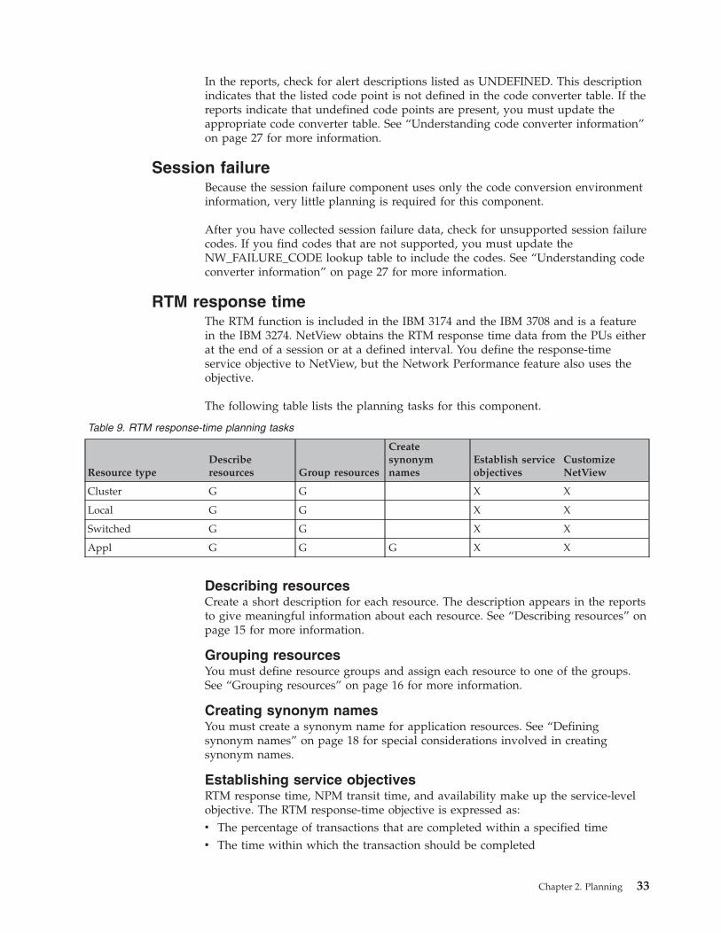
In the reports, check for alert descriptions listed as UNDEFINED. This description
indicates that the listed code point is not defined in the code converter table. If the
reports indicate that undefined code points are present, you must update the
appropriate code converter table. See “Understanding code converter information”
on page 27 for more information.
Session failure
Because the session failure component uses only the code conversion environment
information, very little planning is required for this component.
After you have collected session failure data, check for unsupported session failure
codes. If you find codes that are not supported, you must update the
NW_FAILURE_CODE lookup table to include the codes. See “Understanding code
converter information” on page 27 for more information.
RTM response time
The RTM function is included in the IBM 3174 and the IBM 3708 and is a feature
in the IBM 3274. NetView obtains the RTM response time data from the PUs either
at the end of a session or at a defined interval. You define the response-time
service objective to NetView, but the Network Performance feature also uses the
objective.
The following table lists the planning tasks for this component.
Table 9. RTM response-time planning tasks
Resource type
Describe
resources Group resources
Create
synonym
names
Establish service
objectives
Customize
NetView
Cluster G G X X
Local G G X X
Switched G G X X
Appl G G G X X
Describing resources
Create a short description for each resource. The description appears in the reports
to give meaningful information about each resource. See “Describing resources” on
page 15 for more information.
Grouping resources
You must define resource groups and assign each resource to one of the groups.
See “Grouping resources” on page 16 for more information.
Creating synonym names
You must create a synonym name for application resources. See “Defining
synonym names” on page 18 for special considerations involved in creating
synonym names.
Establishing service objectives
RTM response time, NPM transit time, and availability make up the service-level
objective. The RTM response-time objective is expressed as:
v The percentage of transactions that are completed within a specified time
v The time within which the transaction should be completed
Chapter 2. Planning 33
The NetView PCLASS definition establishes the service objective for the RTM
response time. The PCLASS parameter OBJTIME defines the time within which the
transaction should be completed. The OBJPCT parameter defines the percentage of
transactions that should be completed within the specified time (OBJTIME). You
can define different objectives for different parts of your network and use the
NetView MAPSESS definition to specify the response-time objective (PCLASS) that
each LU uses.
To plan the response-time objective, follow these guidelines:
v Determine the response time objectives necessary for the network. Each objective
requires a separate set of PCLASS definitions. If your installation has a
service-level agreement, use the agreement values as the objective.
v Study the naming convention of your installation to determine ways to simplify
the MAPSESS definitions. You must create MAPSESS definitions so each LU
(terminal) uses the correct objective (PCLASS).
Refer to Network Performance Feature Reference for detailed information on using the
PCLASS and MAPSESS definitions.
Customizing NetView
The Network Performance feature uses data from NetView to report on RTM
response time. NetView customization is described in Chapter 7, “Customizing
NetView and NPM,” on page 141. When performing NetView customization, pay
special attention to these considerations:
v NetView always writes RTM data to SMF when a session ends. However, to
help you better analyze network performance, you should customize NetView to
also write RTM data to SMF at a specified time interval. For example, consider a
session that is active from 9:00 to 14:00 but that has a performance problem at
11:00 that causes response times to become very long. If you do not customize
NetView to write RTM data at intervals, the only RTM data is from the end of
the session, and the performance problem appears to have occurred at 14:00. If
you customize NetView to write RTM data to SMF at 20-minute intervals, you
can determine that the increased response time occurs at 11:00. Accurately
determining the time when response-time problems occur lets you search for
other components that have performance problems at the same time.
However, do not define an interval that is too short, because a short reporting
interval can degrade NetView performance and increase the number of SMF
records written.
For more information on specifying reporting intervals, see “nv8—Collect RTM
data and log to SMF” on page 143.
v Customize the NetView PCLASS and MAPSESS definitions based on the
planning done during “Establishing service objectives” on page 33.
For information on customizing these definitions, see “npm14—Define
transit-time objective” on page 152.
NPM transit time
By using data from NPM, the Network Performance feature can report on host,
network, and operator transit times as seen from VTAM. So NPM can measure the
network and operator transit times, an application must either use definite
response (DR) or have NPM set definite response dynamically. You must determine
if you want reports to include information about only host transit time or about
host, network, and operator transit times. If you decide to report on network and
operator transit times, determine which applications are set to use definite
response.
34 Tivoli Decision Support for z/OS: Network Performance Feature Installation and Administration
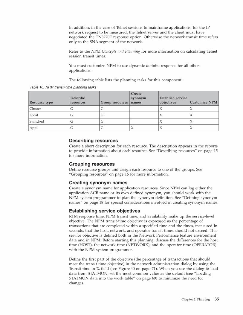
In addition, in the case of Telnet sessions to mainframe applications, for the IP
network request to be measured, the Telnet server and the client must have
negotiated the TN3270E response option. Otherwise the network transit time refers
only to the SNA segment of the network.
Refer to the NPM Concepts and Planning for more information on calculating Telnet
session transit times.
You must customize NPM to use dynamic definite response for all other
applications.
The following table lists the planning tasks for this component.
Table 10. NPM transit-time planning tasks
Resource type
Describe
resources Group resources
Create
synonym
names
Establish service
objectives Customize NPM
Cluster G G X X
Local G G X X
Switched G G X X
Appl G G X X X
Describing resources
Create a short description for each resource. The description appears in the reports
to provide information about each resource. See “Describing resources” on page 15
for more information.
Grouping resources
Define resource groups and assign each resource to one of the groups. See
“Grouping resources” on page 16 for more information.
Creating synonym names
Create a synonym name for application resources. Since NPM can log either the
application ACB name or its own defined synonym, you should work with the
NPM system programmer to plan the synonym definition. See “Defining synonym
names” on page 18 for special considerations involved in creating synonym names.
Establishing service objectives
RTM response time, NPM transit time, and availability make up the service-level
objective. The NPM transit-time objective is expressed as the percentage of
transactions that are completed within a specified time and the times, measured in
seconds, that the host, network, and operator transit times should not exceed. This
service objective is defined both in the Network Performance feature environment
data and in NPM. Before starting this planning, discuss the differences for the host
time (HOST), the network time (NETWORK), and the operator time (OPERATOR)
with the NPM system programmer.
Define the first part of the objective (the percentage of transactions that should
meet the transit time objective) in the network administration dialog by using the
Transit time in % field (see Figure 40 on page 71). When you use the dialog to load
data from STATMON, set the most common value as the default (see “Loading
STATMON data into the work table” on page 69) to minimize the need for
changes.
Chapter 2. Planning 35
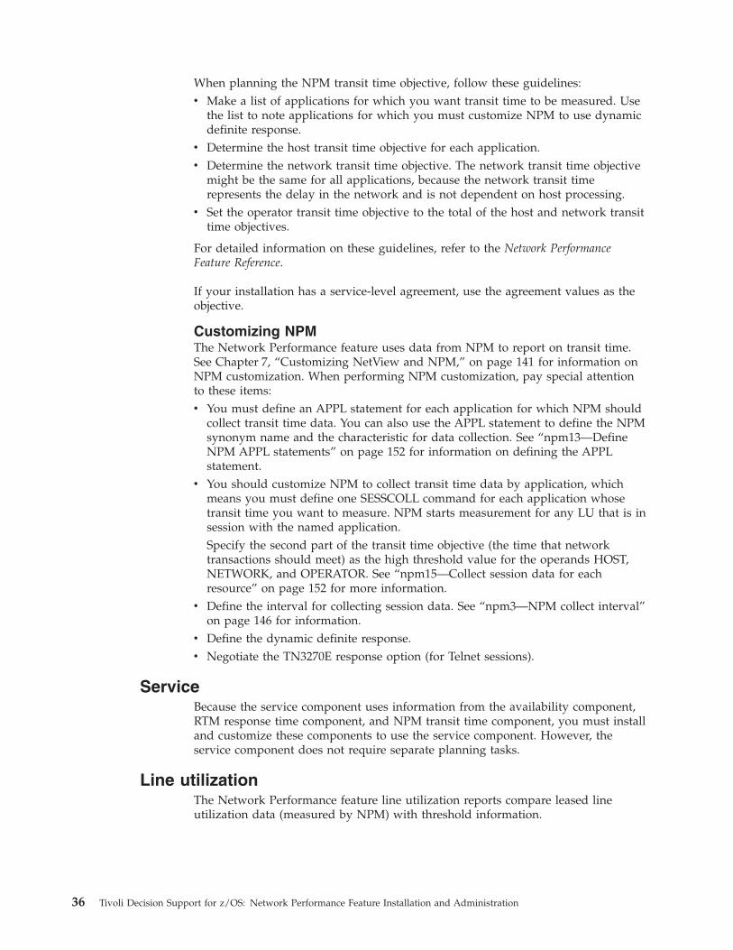
When planning the NPM transit time objective, follow these guidelines:
v Make a list of applications for which you want transit time to be measured. Use
the list to note applications for which you must customize NPM to use dynamic
definite response.
v Determine the host transit time objective for each application.
v Determine the network transit time objective. The network transit time objective
might be the same for all applications, because the network transit time
represents the delay in the network and is not dependent on host processing.
v Set the operator transit time objective to the total of the host and network transit
time objectives.
For detailed information on these guidelines, refer to the Network Performance
Feature Reference.
If your installation has a service-level agreement, use the agreement values as the
objective.
Customizing NPM
The Network Performance feature uses data from NPM to report on transit time.
See Chapter 7, “Customizing NetView and NPM,” on page 141 for information on
NPM customization. When performing NPM customization, pay special attention
to these items:
v You must define an APPL statement for each application for which NPM should
collect transit time data. You can also use the APPL statement to define the NPM
synonym name and the characteristic for data collection. See “npm13—Define
NPM APPL statements” on page 152 for information on defining the APPL
statement.
v You should customize NPM to collect transit time data by application, which
means you must define one SESSCOLL command for each application whose
transit time you want to measure. NPM starts measurement for any LU that is in
session with the named application.
Specify the second part of the transit time objective (the time that network
transactions should meet) as the high threshold value for the operands HOST,
NETWORK, and OPERATOR. See “npm15—Collect session data for each
resource” on page 152 for more information.
v Define the interval for collecting session data. See “npm3—NPM collect interval”
on page 146 for information.
v Define the dynamic definite response.
v Negotiate the TN3270E response option (for Telnet sessions).
Service
Because the service component uses information from the availability component,
RTM response time component, and NPM transit time component, you must install
and customize these components to use the service component. However, the
service component does not require separate planning tasks.
Line utilization
The Network Performance feature line utilization reports compare leased line
utilization data (measured by NPM) with threshold information.
36 Tivoli Decision Support for z/OS: Network Performance Feature Installation and Administration
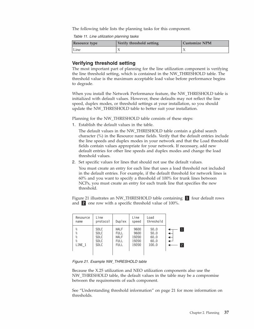
The following table lists the planning tasks for this component.
Table 11. Line utilization planning tasks
Resource type Verify threshold setting Customize NPM
Line X X
Verifying threshold setting
The most important part of planning for the line utilization component is verifying
the line threshold setting, which is contained in the NW_THRESHOLD table. The
threshold value is the maximum acceptable load value before performance begins
to degrade.
When you install the Network Performance feature, the NW_THRESHOLD table is
initialized with default values. However, these defaults may not reflect the line
speed, duplex modes, or threshold settings at your installation, so you should
update the NW_THRESHOLD table to better suit your installation.
Planning for the NW_THRESHOLD table consists of these steps:
1. Establish the default values in the table.
The default values in the NW_THRESHOLD table contain a global search
character (%) in the Resource name fields. Verify that the default entries include
the line speeds and duplex modes in your network and that the Load threshold
fields contain values appropriate for your network. If necessary, add new
default entries for other line speeds and duplex modes and change the load
threshold values.
2. Set specific values for lines that should not use the default values.
You must create an entry for each line that uses a load threshold not included
in the default entries. For example, if the default threshold for network lines is
60% and you want to specify a threshold of 100% for trunk lines between
NCPs, you must create an entry for each trunk line that specifies the new
threshold.
Figure 21 illustrates an NW_THRESHOLD table containing �1� four default rows
and �2� one row with a specific threshold value of 100%.
Because the X.25 utilization and NEO utilization components also use the
NW_THRESHOLD table, the default values in the table may be a compromise
between the requirements of each component.
See “Understanding threshold information” on page 21 for more information on
thresholds.
Resourcename
%%%%LINE_1
SDLCSDLCSDLCSDLCSDLC
HALFFULLHALFFULLFULL
96009600192001920019200
50.050.060.060.0100.0
Lineprotocol
Linespeed
LoadthresholdDuplex
1
2
Figure 21. Example NW_THRESHOLD table
Chapter 2. Planning 37
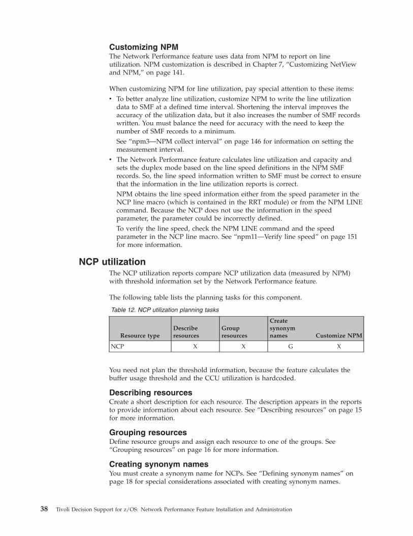
Customizing NPM
The Network Performance feature uses data from NPM to report on line
utilization. NPM customization is described in Chapter 7, “Customizing NetView
and NPM,” on page 141.
When customizing NPM for line utilization, pay special attention to these items:
v To better analyze line utilization, customize NPM to write the line utilization
data to SMF at a defined time interval. Shortening the interval improves the
accuracy of the utilization data, but it also increases the number of SMF records
written. You must balance the need for accuracy with the need to keep the
number of SMF records to a minimum.
See “npm3—NPM collect interval” on page 146 for information on setting the
measurement interval.
v The Network Performance feature calculates line utilization and capacity and
sets the duplex mode based on the line speed definitions in the NPM SMF
records. So, the line speed information written to SMF must be correct to ensure
that the information in the line utilization reports is correct.
NPM obtains the line speed information either from the speed parameter in the
NCP line macro (which is contained in the RRT module) or from the NPM LINE
command. Because the NCP does not use the information in the speed
parameter, the parameter could be incorrectly defined.
To verify the line speed, check the NPM LINE command and the speed
parameter in the NCP line macro. See “npm11—Verify line speed” on page 151
for more information.
NCP utilization
The NCP utilization reports compare NCP utilization data (measured by NPM)
with threshold information set by the Network Performance feature.
The following table lists the planning tasks for this component.
Table 12. NCP utilization planning tasks
Resource type
Describe
resources
Group
resources
Create
synonym
names Customize NPM
NCP X X G X
You need not plan the threshold information, because the feature calculates the
buffer usage threshold and the CCU utilization is hardcoded.
Describing resources
Create a short description for each resource. The description appears in the reports
to provide information about each resource. See “Describing resources” on page 15
for more information.
Grouping resources
Define resource groups and assign each resource to one of the groups. See
“Grouping resources” on page 16 for more information.
Creating synonym names
You must create a synonym name for NCPs. See “Defining synonym names” on
page 18 for special considerations associated with creating synonym names.
38 Tivoli Decision Support for z/OS: Network Performance Feature Installation and Administration
Customizing NPM
The Network Performance feature uses data from NPM to report on NCP
utilization. When performing NPM customization, pay special attention to the
measurement interval.
To better analyze NCP utilization, customize NPM to write the NCP utilization
data to SMF at a defined time interval. Shortening the interval improves the
accuracy of the utilization data, but it also increases the number of SMF records
written. You must balance the need for accuracy with the need to keep the number
of SMF records to a minimum.
See “npm3—NPM collect interval” on page 146 for information on setting the
measurement interval.
NPM internal utilization
Because the NPM internal utilization component does not use environment
information, planning for this component involves only these considerations:
v Verifying the NPM name
v Determining the collect interval
v Customizing NPM
NPM name
The Network Performance feature builds the name under which NPM data is
logged by concatenating the system ID and subsystem ID (=NPM) found in the
SMF record header. If your reports include data from more than one NPM, verify
that the system ID for the host (where the NPMs reside) is different.
Collect interval
NPM writes information about its own utilization to SMF with an interval equal to
the defined NPM base interval. Verify that the base interval is set to an acceptable
value not only for this component, but also for the collect intervals for the other
components.
Note: The NPM base interval value determines how you must define the collect
interval for other utilization components.
See “npm3—NPM collect interval” on page 146 for information on setting the
measurement interval.
Customizing NPM
Customize NPM to write the internal utilization data to SMF (see Chapter 7,
“Customizing NetView and NPM,” on page 141).
PU utilization
Because the PU utilization component does not use environment information,
planning for this component involves considering only NPM customization.
Customize NPM to collect the PU utilization data (see Chapter 7, “Customizing
NetView and NPM,” on page 141).
NV/SM utilization
Because the NV/SM utilization component does not use environment information,
planning for this component involves considering only the NetView name and
NetView customization.
Chapter 2. Planning 39
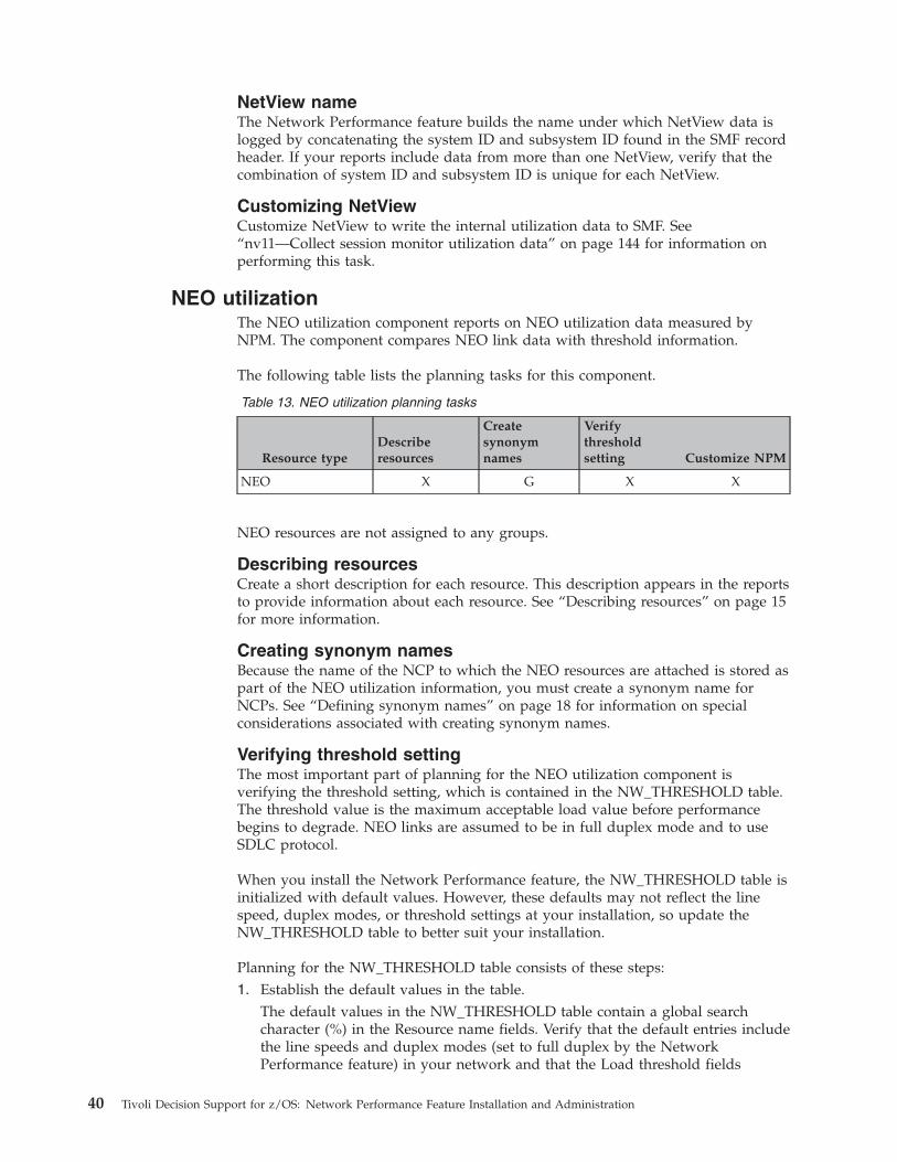
NetView name
The Network Performance feature builds the name under which NetView data is
logged by concatenating the system ID and subsystem ID found in the SMF record
header. If your reports include data from more than one NetView, verify that the
combination of system ID and subsystem ID is unique for each NetView.
Customizing NetView
Customize NetView to write the internal utilization data to SMF. See
“nv11—Collect session monitor utilization data” on page 144 for information on
performing this task.
NEO utilization
The NEO utilization component reports on NEO utilization data measured by
NPM. The component compares NEO link data with threshold information.
The following table lists the planning tasks for this component.
Table 13. NEO utilization planning tasks
Resource type
Describe
resources
Create
synonym
names
Verify
threshold
setting Customize NPM
NEO X G X X
NEO resources are not assigned to any groups.
Describing resources
Create a short description for each resource. This description appears in the reports
to provide information about each resource. See “Describing resources” on page 15
for more information.
Creating synonym names
Because the name of the NCP to which the NEO resources are attached is stored as
part of the NEO utilization information, you must create a synonym name for
NCPs. See “Defining synonym names” on page 18 for information on special
considerations associated with creating synonym names.
Verifying threshold setting
The most important part of planning for the NEO utilization component is
verifying the threshold setting, which is contained in the NW_THRESHOLD table.
The threshold value is the maximum acceptable load value before performance
begins to degrade. NEO links are assumed to be in full duplex mode and to use
SDLC protocol.
When you install the Network Performance feature, the NW_THRESHOLD table is
initialized with default values. However, these defaults may not reflect the line
speed, duplex modes, or threshold settings at your installation, so update the
NW_THRESHOLD table to better suit your installation.
Planning for the NW_THRESHOLD table consists of these steps:
1. Establish the default values in the table.
The default values in the NW_THRESHOLD table contain a global search
character (%) in the Resource name fields. Verify that the default entries include
the line speeds and duplex modes (set to full duplex by the Network
Performance feature) in your network and that the Load threshold fields
40 Tivoli Decision Support for z/OS: Network Performance Feature Installation and Administration
contain values appropriate for your network. If necessary, add new default
entries for other line speeds and duplex modes and change the load threshold
values.
2. Set specific values for lines that should not use the default values.
You must create an entry for each line that uses a load threshold not included
in the default entries. For example, if the default threshold for network lines is
60% and you want to specify a threshold of 100% for trunk lines between
NCPs, you must create an entry for each trunk line that specifies the new
threshold.
Figure 22 illustrates NW_THRESHOLD table containing �1� four default rows and
�2� one row with a specific threshold value of 100%.
Because the line utilization and X.25 utilization components also use the
NW_THRESHOLD table, the default values in the table may be a compromise
between the requirements of each component.
See “Understanding threshold information” on page 21 for more information on
thresholds.
Customizing NPM
The Network Performance feature uses data from NPM to report on NEO
utilization. NPM customization is described in Chapter 7, “Customizing NetView
and NPM,” on page 141.
When customizing NPM for line utilization, pay special attention to these
considerations:
v To better analyze NEO utilization, customize NPM to write the NEO utilization
data to SMF at a defined time interval. Shortening the interval improves the
accuracy of the utilization data, but it also increases the number of SMF records
written. You must balance the need for accuracy with the need to keep the
number of SMF records to a minimum.
See “npm3—NPM collect interval” on page 146 for information on setting the
measurement interval.
v The Network Performance feature calculates NEO link utilization based on the
line speed definitions in the NPM SMF records. So, the line speed information
written to SMF must be correct to ensure that the information in the line
utilization reports is correct.
NPM obtains the line speed information either from the speed parameter in the
NCP line macro (which is contained in the RRT module) or from the NPM LINE
command. Because the NCP does not use the information in the speed
parameter, the parameter could be incorrectly defined.
Resourcename
%%%%LINE_1
SDLCSDLCSDLCSDLCSDLC
HALFFULLHALFFULLFULL
96009600192001920019200
50.050.060.060.0100.0
Lineprotocol
Linespeed
LoadthresholdDuplex
1
2
Figure 22. Example NW_THRESHOLD table
Chapter 2. Planning 41
To verify the line speed, check the NPM LINE command and the speed
parameter in the NCP line macro. See “npm11—Verify line speed” on page 151
for more information.
NTRI utilization
The NTRI utilization component reports on the utilization data measured by NPM
for token-ring sessions that pass through the token-ring interface coupler (TIC).
The feature does not compare the utilization data with threshold information.
The following table lists the planning tasks for this component.
Table 14. NTRI utilization planning tasks
Resource type Describe resources
Create synonym
names Customize NPM
NTRI X X X
Describing resources
Create a short description for each resource. The description appears in the reports
to provide information about each resource. See “Describing resources” on page 15
for more information.
Creating synonym names
Because the name of the NCP that NTRI is part of is stored as part of the NTRI
utilization information, you must create a synonym name for NCPs. See “Defining
synonym names” on page 18 for information on special considerations associated
with creating synonym names.
Customizing NPM
The Network Performance feature uses data from NPM to report on NTRI
utilization. NPM customization is described in Chapter 7, “Customizing NetView
and NPM,” on page 141.
To better analyze NTRI utilization, customize NPM to write the NTRI utilization
data to SMF at a defined time interval. Shortening the interval improves the
accuracy of the utilization data, but it also increases the number of SMF records
written. You must balance the need for accuracy with the need to keep the number
of SMF records to a minimum.
See “npm3—NPM collect interval” on page 146 for information on setting the
measurement interval.
Frame Relay utilization
The Frame Relay utilization component reports on the utilization data measured by
NPM for token-ring sessions that pass through the token-ring interface coupler
(TIC). The feature does not compare the utilization data with threshold
information.
The following table lists the planning tasks for this component.
Table 15. Frame Relay utilization planning tasks
Resource type Describe resources
Create synonym
names Customize NPM
Frame Relay X X X
42 Tivoli Decision Support for z/OS: Network Performance Feature Installation and Administration
Describing resources
Create a short description for each resource. The description appears in the reports
to provide information about each resource. See “Describing resources” on page 15
for more information.
Creating synonym names
Because the name of the NCP that Frame Relay is part of is stored as part of the
Frame Relay utilization information, you must create a synonym name for NCPs.
See “Defining synonym names” on page 18 for information on special
considerations associated with creating synonym names.
Customizing NPM
The Network Performance feature uses data from NPM to report on Frame Relay
utilization. NPM customization is described in Chapter 7, “Customizing NetView
and NPM,” on page 141.
To better analyze Frame Relay utilization, customize NPM to write the Frame
Relay utilization data to SMF at a defined time interval. Shortening the interval
improves the accuracy of the utilization data, but it also increases the number of
SMF records written. You must balance the need for accuracy with the need to
keep the number of SMF records to a minimum.
See “npm3—NPM collect interval” on page 146 for information on setting the
measurement interval.
LAN utilization
Because the LAN utilization component does not use environment information,
you only need to consider the NPM customization.
The following table lists the planning tasks for this component.
Table 16. LAN utilization planning tasks
Resource type Customize NPM
LAN X
Customizing NPM
The Network Performance feature uses data from NPM to report on LAN
utilization. When performing NPM customization, pay special attention to the
measurement interval.
To better analyze LAN utilization, customize NPM to write the LAN utilization
data to SMF at a defined time interval. Shortening the interval improves the
accuracy of the utilization data, but it also increases the number of SMF records
written. You must balance the need for accuracy with the need to keep the number
of SMF records to a minimum.
See “npm18—Define the LAN collection interval” on page 153 for information on
setting the measurement interval.
If you want to include threshold comparison of the LAN bridge and LAN
segment, set the high threshold parameter in the LBRGCOLL or LSEGCOLL NPM
command. See “npm19—Collect LAN bridge data” on page 155 and
“npm20—Collect LAN segment data” on page 155 for details.
Chapter 2. Planning 43
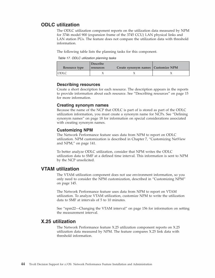
ODLC utilization
The ODLC utilization component reports on the utilization data measured by NPM
for 3746 model 900 (expansion frame of the 3745 CCU) LAN physical links and
LAN station PUs. The feature does not compare the utilization data with threshold
information.
The following table lists the planning tasks for this component.
Table 17. ODLC utilization planning tasks
Resource type
Describe
resources Create synonym names Customize NPM
ODLC X X X
Describing resources
Create a short description for each resource. The description appears in the reports
to provide information about each resource. See “Describing resources” on page 15
for more information.
Creating synonym names
Because the name of the NCP that ODLC is part of is stored as part of the ODLC
utilization information, you must create a synonym name for NCPs. See “Defining
synonym names” on page 18 for information on special considerations associated
with creating synonym names.
Customizing NPM
The Network Performance feature uses data from NPM to report on ODLC
utilization. NPM customization is described in Chapter 7, “Customizing NetView
and NPM,” on page 141.
To better analyze ODLC utilization, consider that NPM writes the ODLC
utilization data to SMF at a defined time interval. This information is sent to NPM
by the NCP unsolicited.
VTAM utilization
The VTAM utilization component does not use environment information, so you
only need to consider the NPM customization, described in “Customizing NPM”
on page 145.
The Network Performance feature uses data from NPM to report on VTAM
utilization. To analyze VTAM utilization, customize NPM to write the utilization
data to SMF at intervals of 5 to 10 minutes.
See “npm22—Changing the VTAM interval” on page 156 for information on setting
the measurement interval.
X.25 utilization
The Network Performance feature X.25 utilization component reports on X.25
utilization data measured by NPM. The feature compares X.25 link data with
threshold information.
44 Tivoli Decision Support for z/OS: Network Performance Feature Installation and Administration
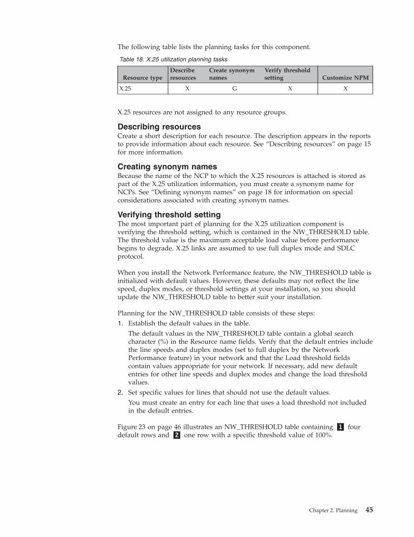
The following table lists the planning tasks for this component.
Table 18. X.25 utilization planning tasks
Resource type
Describe
resources
Create synonym
names
Verify threshold
setting Customize NPM
X.25 X G X X
X.25 resources are not assigned to any resource groups.
Describing resources
Create a short description for each resource. The description appears in the reports
to provide information about each resource. See “Describing resources” on page 15
for more information.
Creating synonym names
Because the name of the NCP to which the X.25 resources is attached is stored as
part of the X.25 utilization information, you must create a synonym name for
NCPs. See “Defining synonym names” on page 18 for information on special
considerations associated with creating synonym names.
Verifying threshold setting
The most important part of planning for the X.25 utilization component is
verifying the threshold setting, which is contained in the NW_THRESHOLD table.
The threshold value is the maximum acceptable load value before performance
begins to degrade. X.25 links are assumed to use full duplex mode and SDLC
protocol.
When you install the Network Performance feature, the NW_THRESHOLD table is
initialized with default values. However, these defaults may not reflect the line
speed, duplex modes, or threshold settings at your installation, so you should
update the NW_THRESHOLD table to better suit your installation.
Planning for the NW_THRESHOLD table consists of these steps:
1. Establish the default values in the table.
The default values in the NW_THRESHOLD table contain a global search
character (%) in the Resource name fields. Verify that the default entries include
the line speeds and duplex modes (set to full duplex by the Network
Performance feature) in your network and that the Load threshold fields
contain values appropriate for your network. If necessary, add new default
entries for other line speeds and duplex modes and change the load threshold
values.
2. Set specific values for lines that should not use the default values.
You must create an entry for each line that uses a load threshold not included
in the default entries.
Figure 23 on page 46 illustrates an NW_THRESHOLD table containing �1� four
default rows and �2� one row with a specific threshold value of 100%.
Chapter 2. Planning 45
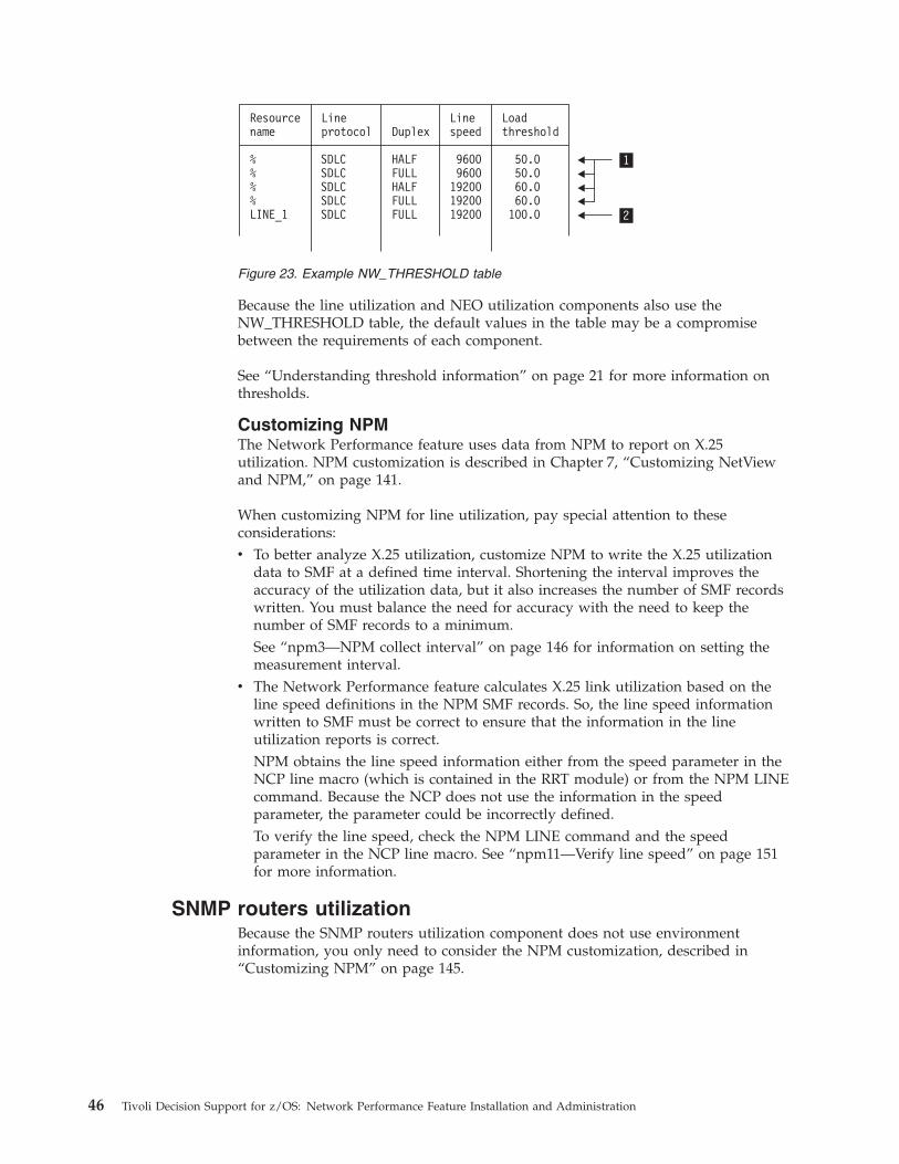
Because the line utilization and NEO utilization components also use the
NW_THRESHOLD table, the default values in the table may be a compromise
between the requirements of each component.
See “Understanding threshold information” on page 21 for more information on
thresholds.
Customizing NPM
The Network Performance feature uses data from NPM to report on X.25
utilization. NPM customization is described in Chapter 7, “Customizing NetView
and NPM,” on page 141.
When customizing NPM for line utilization, pay special attention to these
considerations:
v To better analyze X.25 utilization, customize NPM to write the X.25 utilization
data to SMF at a defined time interval. Shortening the interval improves the
accuracy of the utilization data, but it also increases the number of SMF records
written. You must balance the need for accuracy with the need to keep the
number of SMF records to a minimum.
See “npm3—NPM collect interval” on page 146 for information on setting the
measurement interval.
v The Network Performance feature calculates X.25 link utilization based on the
line speed definitions in the NPM SMF records. So, the line speed information
written to SMF must be correct to ensure that the information in the line
utilization reports is correct.
NPM obtains the line speed information either from the speed parameter in the
NCP line macro (which is contained in the RRT module) or from the NPM LINE
command. Because the NCP does not use the information in the speed
parameter, the parameter could be incorrectly defined.
To verify the line speed, check the NPM LINE command and the speed
parameter in the NCP line macro. See “npm11—Verify line speed” on page 151
for more information.
SNMP routers utilization
Because the SNMP routers utilization component does not use environment
information, you only need to consider the NPM customization, described in
“Customizing NPM” on page 145.
Resourcename
%%%%LINE_1
SDLCSDLCSDLCSDLCSDLC
HALFFULLHALFFULLFULL
96009600192001920019200
50.050.060.060.0100.0
Lineprotocol
Linespeed
LoadthresholdDuplex
1
2
Figure 23. Example NW_THRESHOLD table
46 Tivoli Decision Support for z/OS: Network Performance Feature Installation and Administration
The following table lists the planning tasks for this component.
Table 19. SNMP routers utilization planning tasks
Resource type Customize NPM
SNMP routers X
Customizing NPM
The Network Performance feature uses data from NPM to report on SNMP routers
utilization. When performing NPM customization, pay special attention to the
measurement interval.
To better analyze SNMP routers utilization, customize NPM to write the SNMP
routers utilization data to SMF at a defined time interval. Shortening the interval
improves the accuracy of the utilization data, but it also increases the number of
SMF records written. You must balance the need for accuracy with the need to
keep the number of SMF records to a minimum.
See “npm3—NPM collect interval” on page 146 for information on setting the
measurement interval.
Chapter 2. Planning 47

48 Tivoli Decision Support for z/OS: Network Performance Feature Installation and Administration
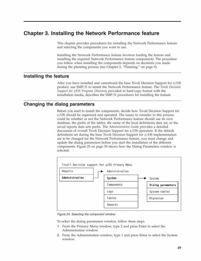
Chapter 3. Installing the Network Performance feature
This chapter provides procedures for installing the Network Performance feature
and selecting the components you want to use.
Installing the Network Performance feature involves loading the feature and
installing the required Network Performance feature components. The procedure
you follow when installing the components depends on decisions you made
during the planning process (see Chapter 2, “Planning,” on page 9).
Installing the feature
After you have installed and customized the base Tivoli Decision Support for z/OS
product, use SMP/E to install the Network Performance feature. The Tivoli Decision
Support for z/OS Program Directory provided in hard-copy format with the
installation media, describes the SMP/E procedures for installing the feature.
Changing the dialog parameters
Before you start to install the components, decide how Tivoli Decision Support for
z/OS should be organized and operated. The issues to consider in this process
could be whether or not the Network Performance feature should use its own
database, the prefix of the tables, the name of the local definitions data set, or the
saved reports data sets prefix. The Administration Guide provides a detailed
discussion of overall Tivoli Decision Support for z/OS operation. If the default
definitions set during the base Tivoli Decision Support for z/OS implementation
are to be changed for the Network Performance feature, you must change and
update the dialog parameters before you start the installation of the different
components. Figure 25 on page 50 shows how the Dialog Parameters window is
selected.
To select the dialog parameters window, follow these steps.
1. From the Primary Menu window, type 2 and press Enter to select the
Administration window.
2. From the Administration window, type 1 and press Enter to select the System
window.
Figure 24. Selecting the component window
49
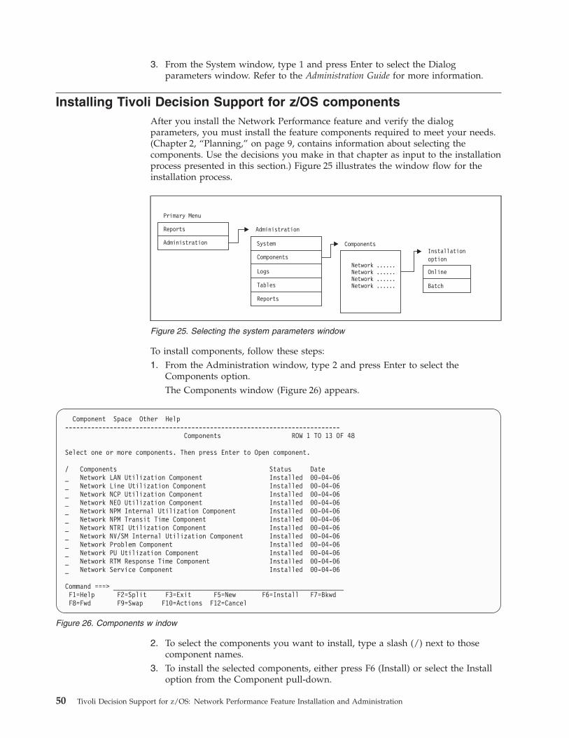
3. From the System window, type 1 and press Enter to select the Dialog
parameters window. Refer to the Administration Guide for more information.
Installing Tivoli Decision Support for z/OS components
After you install the Network Performance feature and verify the dialog
parameters, you must install the feature components required to meet your needs.
(Chapter 2, “Planning,” on page 9, contains information about selecting the
components. Use the decisions you make in that chapter as input to the installation
process presented in this section.) Figure 25 illustrates the window flow for the
installation process.
To install components, follow these steps:
1. From the Administration window, type 2 and press Enter to select the
Components option.
The Components window (Figure 26) appears.
2. To select the components you want to install, type a slash (/) next to those
component names.
3. To install the selected components, either press F6 (Install) or select the Install
option from the Component pull-down.
Primary Menu
Reports
Administration
Administration
Network ......Network ......Network ......Network ......
Components
Components
Logs
Tables
Reports
System
Online
Batch
Installationoption
Figure 25. Selecting the system parameters window
Component Space Other Help
--------------------------------------------------------------------------
Components ROW 1 TO 13 OF 48
Select one or more components. Then press Enter to Open component.
/ Components Status Date
_ Network LAN Utilization Component Installed 00-04-06
_ Network Line Utilization Component Installed 00-04-06
_ Network NCP Utilization Component Installed 00-04-06
_ Network NEO Utilization Component Installed 00-04-06
_ Network NPM Internal Utilization Component Installed 00-04-06
_ Network NPM Transit Time Component Installed 00-04-06
_ Network NTRI Utilization Component Installed 00-04-06
_ Network NV/SM Internal Utilization Component Installed 00-04-06
_ Network Problem Component Installed 00-04-06
_ Network PU Utilization Component Installed 00-04-06
_ Network RTM Response Time Component Installed 00-04-06
_ Network Service Component Installed 00-04-06
Command ===> ______________________________________________________________
F1=Help F2=Split F3=Exit F5=New F6=Install F7=Bkwd
F8=Fwd F9=Swap F10=Actions F12=Cancel
Figure 26. Components w indow
50 Tivoli Decision Support for z/OS: Network Performance Feature Installation and Administration
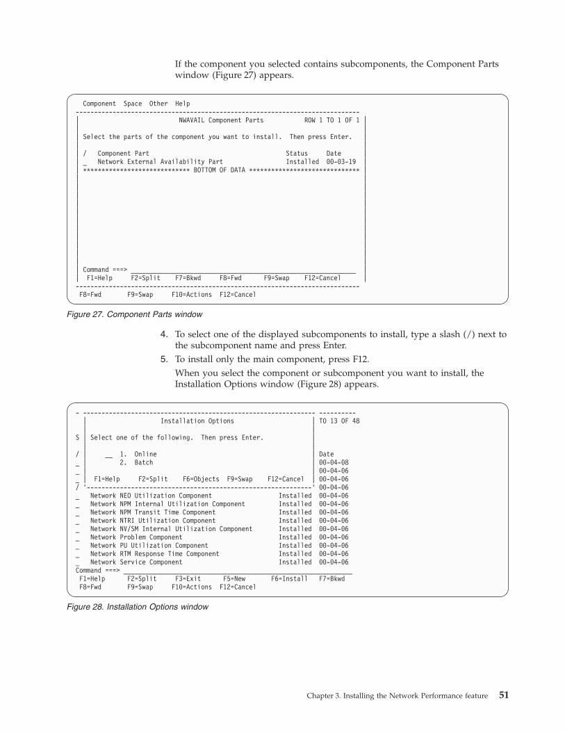
If the component you selected contains subcomponents, the Component Parts
window (Figure 27) appears.
4. To select one of the displayed subcomponents to install, type a slash (/) next to
the subcomponent name and press Enter.
5. To install only the main component, press F12.
When you select the component or subcomponent you want to install, the
Installation Options window (Figure 28) appears.
Component Space Other Help
-----------------------------------------------------------------------------
| NWAVAIL Component Parts ROW 1 TO 1 OF 1 |
| |
| Select the parts of the component you want to install. Then press Enter. |
| |
| / Component Part Status Date |
| _ Network External Availability Part Installed 00-03-19 |
| ***************************** BOTTOM OF DATA ****************************** |
| |
| |
| |
| |
| |
| |
| |
| |
| |
| |
| |
| Command ===> _____________________________________________________________ |
| F1=Help F2=Split F7=Bkwd F8=Fwd F9=Swap F12=Cancel |
-----------------------------------------------------------------------------
F8=Fwd F9=Swap F10=Actions F12=Cancel
Figure 27. Component Parts window
- --------------------------------------------------------------- ----------
| Installation Options | TO 13 OF 48
| |
S | Select one of the following. Then press Enter. |
| |
/ | __ 1. Online | Date
_ | 2. Batch | 00-04-08
_ | | 00-04-06
_ | F1=Help F2=Split F6=Objects F9=Swap F12=Cancel | 00-04-06
/ ’-------------------------------------------------------------’ 00-04-06
_ Network NEO Utilization Component Installed 00-04-06
_ Network NPM Internal Utilization Component Installed 00-04-06
_ Network NPM Transit Time Component Installed 00-04-06
_ Network NTRI Utilization Component Installed 00-04-06
_ Network NV/SM Internal Utilization Component Installed 00-04-06
_ Network Problem Component Installed 00-04-06
_ Network PU Utilization Component Installed 00-04-06
_ Network RTM Response Time Component Installed 00-04-06
_ Network Service Component Installed 00-04-06
Command ===> ______________________________________________________________
F1=Help F2=Split F3=Exit F5=New F6=Install F7=Bkwd
F8=Fwd F9=Swap F10=Actions F12=Cancel
Figure 28. Installation Options window
Chapter 3. Installing the Network Performance feature 51
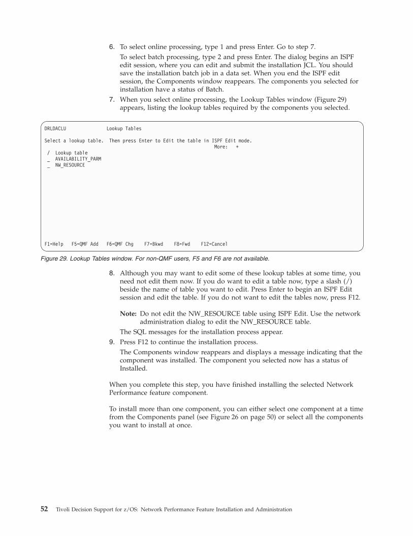
6. To select online processing, type 1 and press Enter. Go to step 7.
To select batch processing, type 2 and press Enter. The dialog begins an ISPF
edit session, where you can edit and submit the installation JCL. You should
save the installation batch job in a data set. When you end the ISPF edit
session, the Components window reappears. The components you selected for
installation have a status of Batch.
7. When you select online processing, the Lookup Tables window (Figure 29)
appears, listing the lookup tables required by the components you selected.
8. Although you may want to edit some of these lookup tables at some time, you
need not edit them now. If you do want to edit a table now, type a slash (/)
beside the name of table you want to edit. Press Enter to begin an ISPF Edit
session and edit the table. If you do not want to edit the tables now, press F12.
Note: Do not edit the NW_RESOURCE table using ISPF Edit. Use the network
administration dialog to edit the NW_RESOURCE table.
The SQL messages for the installation process appear.
9. Press F12 to continue the installation process.
The Components window reappears and displays a message indicating that the
component was installed. The component you selected now has a status of
Installed.
When you complete this step, you have finished installing the selected Network
Performance feature component.
To install more than one component, you can either select one component at a time
from the Components panel (see Figure 26 on page 50) or select all the components
you want to install at once.
DRLDACLU Lookup Tables
Select a lookup table. Then press Enter to Edit the table in ISPF Edit mode.
More: +
/ Lookup table
_ AVAILABILITY_PARM
_ NW_RESOURCE
F1=Help F5=QMF Add F6=QMF Chg F7=Bkwd F8=Fwd F12=Cancel
Figure 29. Lookup Tables window. For non-QMF users, F5 and F6 are not available.
52 Tivoli Decision Support for z/OS: Network Performance Feature Installation and Administration

Before you can use the Network Performance feature, you must define the
environment information required by the installed components and customize
NetView and NPM to support the components. See “Chapter 4, “Administering
Tivoli Decision Support for z/OS and the Network Performance feature”” for
information on defining the environment information and “Chapter 7,
“Customizing NetView and NPM”” for information on customizing NetView and
NPM.
Chapter 3. Installing the Network Performance feature 53

54 Tivoli Decision Support for z/OS: Network Performance Feature Installation and Administration
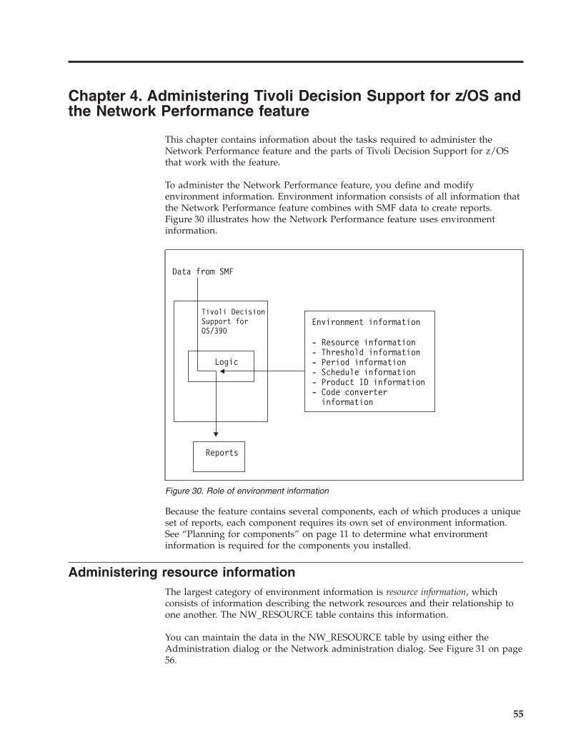
Chapter 4. Administering Tivoli Decision Support for z/OS and
the Network Performance feature
This chapter contains information about the tasks required to administer the
Network Performance feature and the parts of Tivoli Decision Support for z/OS
that work with the feature.
To administer the Network Performance feature, you define and modify
environment information. Environment information consists of all information that
the Network Performance feature combines with SMF data to create reports.
Figure 30 illustrates how the Network Performance feature uses environment
information.
Because the feature contains several components, each of which produces a unique
set of reports, each component requires its own set of environment information.
See “Planning for components” on page 11 to determine what environment
information is required for the components you installed.
Administering resource information
The largest category of environment information is resource information, which
consists of information describing the network resources and their relationship to
one another. The NW_RESOURCE table contains this information.
You can maintain the data in the NW_RESOURCE table by using either the
Administration dialog or the Network administration dialog. See Figure 31 on page
56.
Figure 30. Role of environment information
55
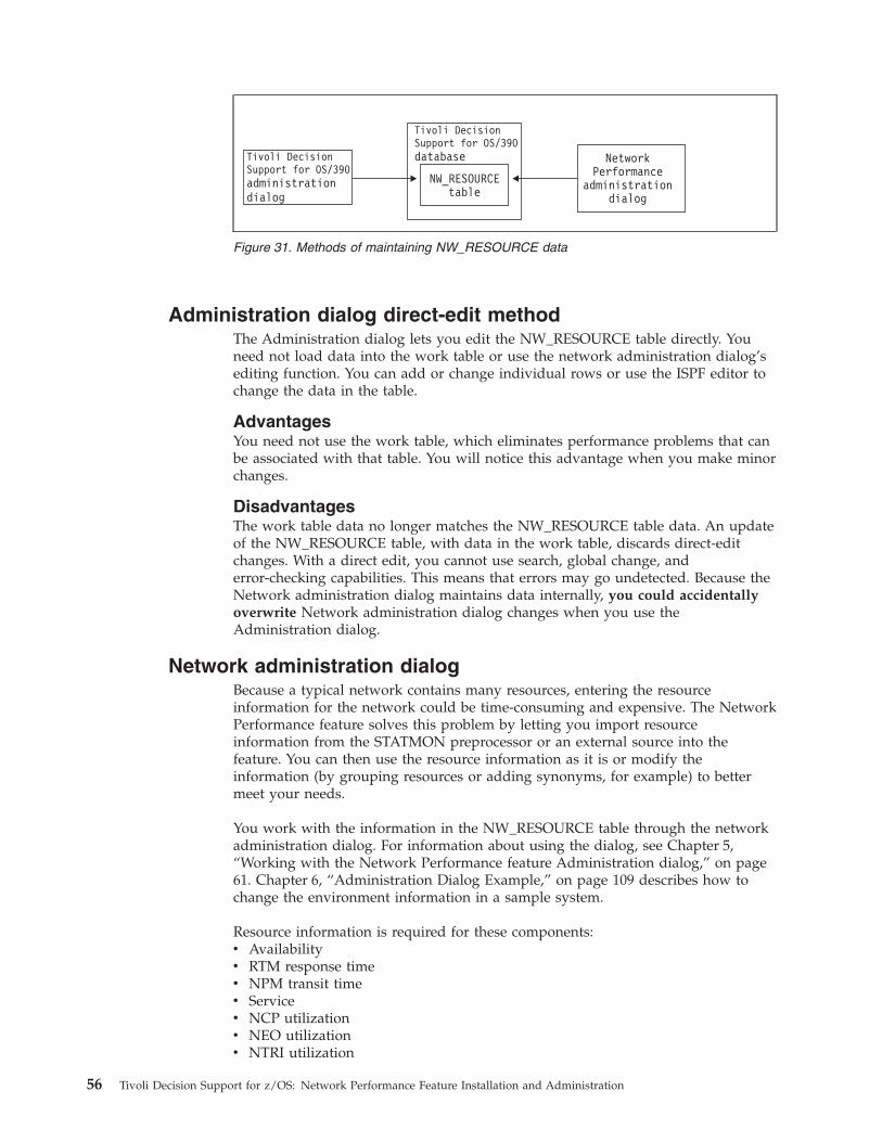
Administration dialog direct-edit method
The Administration dialog lets you edit the NW_RESOURCE table directly. You
need not load data into the work table or use the network administration dialog’s
editing function. You can add or change individual rows or use the ISPF editor to
change the data in the table.
Advantages
You need not use the work table, which eliminates performance problems that can
be associated with that table. You will notice this advantage when you make minor
changes.
Disadvantages
The work table data no longer matches the NW_RESOURCE table data. An update
of the NW_RESOURCE table, with data in the work table, discards direct-edit
changes. With a direct edit, you cannot use search, global change, and
error-checking capabilities. This means that errors may go undetected. Because the
Network administration dialog maintains data internally, you could accidentally
overwrite Network administration dialog changes when you use the
Administration dialog.
Network administration dialog
Because a typical network contains many resources, entering the resource
information for the network could be time-consuming and expensive. The Network
Performance feature solves this problem by letting you import resource
information from the STATMON preprocessor or an external source into the
feature. You can then use the resource information as it is or modify the
information (by grouping resources or adding synonyms, for example) to better
meet your needs.
You work with the information in the NW_RESOURCE table through the network
administration dialog. For information about using the dialog, see Chapter 5,
“Working with the Network Performance feature Administration dialog,” on page
61. Chapter 6, “Administration Dialog Example,” on page 109 describes how to
change the environment information in a sample system.
Resource information is required for these components:
v Availability
v RTM response time
v NPM transit time
v Service
v NCP utilization
v NEO utilization
v NTRI utilization
Figure 31. Methods of maintaining NW_RESOURCE data
56 Tivoli Decision Support for z/OS: Network Performance Feature Installation and Administration
v ODLC utilization
v X.25 utilization
v Frame Relay utilization
Administering threshold information
The threshold information, contained in the NW_THRESHOLD table, consists of
utilization levels for line resources. The feature reports on the percentage of time or
the number of measurement intervals during which the utilization exceeded the
level defined in NW_THRESHOLD. See “Understanding threshold information” on
page 21 for information on determining the contents of this table.
To modify the information in the NW_THRESHOLD table, use the procedure for
modifying tables in the Administration dialog. Refer to Administration Guide for
information on modifying this table.
These components require the information in NW_THRESHOLD:
v Line utilization
v NEO utilization
v X.25 utilization
Administering period tables
The period tables, SPECIAL_DAY, DAY_OF_WEEK, and PERIOD_PLAN, identify
the specific day or the day of the week and period of the day during which data
was collected. The DAY_OF_WEEK table specifies day type information for each
day in the week (for example, MON, TUE). The SPECIAL_DAY table specifies day
type information for specific dates such as holidays (for example, 1993-12-25 could
be identified as HOLIDAY). The PERIOD_PLAN table specifies the period type
during which the SMF data was collected (for example, data collected at 10:00 is
identified as having been collected during the PRIME period; data collected at
19:00 is identified as having been collected during the NIGHT period). These
schedule tables are not unique to the Network Performance feature, but apply to
all system resources. See “Understanding period information” on page 22 for
information on determining the contents of these tables.
Note: The date notation (for example, 1993-12-25) is a default that can be changed
in QMF if you have QMF installed.
To modify the information in the SPECIAL_DATE, DAY_OF_WEEK, and
PERIOD_PLAN tables, use the procedure for modifying tables in the
Administration dialog. Refer to Administration Guide for information on modifying
these tables.
All components except availability and configuration require the information in the
period tables.
Administering the schedule table
The SCHEDULE table identifies the times during each day when resources are
expected to be available. These times usually correspond with normal working
hours for the work week and reduced hours for weekends and holidays. When the
feature records availability data, it checks the day type and time against the
information in the SCHEDULE table to determine if the measurements are
expected to meet the availability and stability service-level objectives. See
“Understanding schedule information” on page 24 for information on determining
the contents of this table.
Chapter 4. Administrating 57
To modify the information in the SCHEDULE table, use the procedure for
modifying tables in the Administration dialog. Refer to Administration Guide for
information on modifying this table.
The availability component requires the information in the SCHEDULE table.
Administering the product ID table
When the Network Performance feature processes problem data, it converts the
hexadecimal product ID or block ID supplied in the SMF record to a more easily
understood product name. To accomplish this task, the feature looks up the
product ID or block ID in the NW_PRODUCT_ID table, which lists product names,
resource types, and hierarchy information for each possible identifier. The feature
then uses the information from the table when updating the
NW_ALERT_BASIC_H and NW_ALERT_GENERIC_H tables. See “Understanding
code converter information” on page 27 for information on determining the
contents of this table.
To modify the information in the NW_PRODUCT_ID table, use the procedure for
modifying tables in the Administration dialog. Refer to Administration Guide for
information on modifying these tables.
The problem component requires the information in the product ID tables.
Administering code converter tables
When NetView writes session failure and problem data to the SMF log, it identifies
the problem by means of a hexadecimal code. To make the reports more
understandable, the Network Performance feature converts these codes to text
descriptions. Although these tables all contain default settings, you may want to
add or change the information in the tables.
The code converter tables and their functions are:
NW_ALERT_TYPE
Converts NetView hardware monitor alert or event types in long and short
text descriptions
NW_FAILURE_CODE
Converts session failure codes to text descriptions
NW_GENERAL_CAUSE
Converts general cause codes to long and short text descriptions
NW_SPECIFIC_CAUSE
Converts NetView hardware-monitor-specific component codes to short
and long text descriptions
NW_ALERT_DESC
Converts generic alert descriptions to code points
NW_PROBABLE_CAUSE
Converts probable cause descriptions to probable cause code points
See “Understanding code converter information” on page 27 for information on
determining the contents of these tables.
58 Tivoli Decision Support for z/OS: Network Performance Feature Installation and Administration

To modify the information in the code converter tables, use the procedure for
modifying tables in the Administration dialog. Refer to Administration Guide for
information on modifying these tables.
The problem and session failure components require the information in the code
converter tables.
Chapter 4. Administrating 59

60 Tivoli Decision Support for z/OS: Network Performance Feature Installation and Administration
Chapter 5. Working with the Network Performance feature
Administration dialog
This chapter contains procedures for using the network administration dialog to
load and modify resource data and to update the NW_RESOURCE table in the
Tivoli Decision Support for z/OS database.
After you complete the installation process (described in “Chapter 3, “Installing the
Network Performance feature””), you must define your network and service-level
information to the feature. The Network Performance feature administration dialog
lets you define and modify the network resource information, which describes
your network to the feature. The network resource information describes items
such as the network configuration, network resources, and the connections
between resources.
Understanding the need for the network administration dialog
The network administration dialog is a tool that helps you work with the network
resource data stored in the NW_RESOURCE table. This table is part of the Tivoli
Decision Support for z/OS database and describes the network to the Network
Performance feature. Defining the contents of the NW_RESOURCE table can be a
complex task in some situations (for example, defining synonym translations). The
dialog helps make these complex tasks more simple to perform and it also
provides functions to verify your definitions.
The dialog minimizes the amount of typing you do when defining resources by
using information from STATMON to define resources. When you load the
STATMON data, the dialog uses default information (which you specify) and
definition rules to complete the definition of the resources.
If your installation has a file of network resource information, you can use the
dialog to import that data into the NW_RESOURCE table. Before you import the
data, you must create a program to put the resource data into the format required
by the Network Performance feature. If you import data from an external source,
you can use the administration dialog to update only the NW_RESOURCE table,
and maintain the resource information in the external source.
The network administration dialog does not work directly with the
NW_RESOURCE table in the database, but stores the data in an ISPF work table.
From the work table, you can use the dialog to edit, export, or verify the resource
data. After you have finished working with the data in the work table, you must
update the NW_RESOURCE table with the data from the work table.
Attention: Do not use a split screen to start multiple sessions of the network
administration dialog, or let more than one user start the dialog at a time. Either of
these situations may cause the contents of the NW_RESOURCE table and the ISPF
work table to differ and result in a corrupted NW_RESOURCE table.
Network administration dialog functions
Figure 32 provides an overview of the administration dialog’s main functions.
61
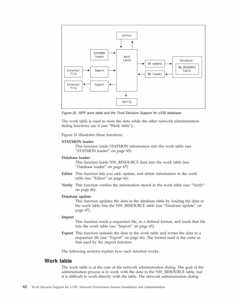
The work table is used to store the data while the other network administration
dialog functions use it (see “Work table”).
Figure 32 illustrates these functions:
STATMON loader
This function loads STATMON information into the work table (see
“STATMON loader” on page 65).
Database loader
This function loads NW_RESOURCE data into the work table (see
“Database loader” on page 67).
Editor This function lets you add, update, and delete information in the work
table (see “Editor” on page 66).
Verify This function verifies the information stored in the work table (see “Verify”
on page 66).
Database update
This function updates the data in the database table by loading the data in
the work table into the NW_RESOURCE table (see “Database update” on
page 67).
Import
This function reads a sequential file, in a defined format, and loads that file
into the work table (see “Import” on page 65).
Export This function unloads the data in the work table and writes the data to a
sequential file (see “Export” on page 66). The format used is the same as
that used by the import function.
The following sections explain how each function works.
Work table
The work table is at the core of the network administration dialog. The goal of the
administration process is to work with the data in the NW_RESOURCE table, but
it is difficult to work directly with the table. The network administration dialog
Externalfile
Import
STATMONloader Work
table
Editor
Verify
DB update
DB loader
Database
NW_RESOURCEtable
Externalfile
Export
Figure 32. ISPF work table and the Tivoli Decision Support for z/OS database
62 Tivoli Decision Support for z/OS: Network Performance Feature Installation and Administration
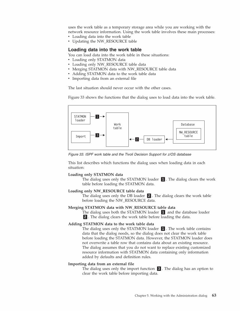
uses the work table as a temporary storage area while you are working with the
network resource information. Using the work table involves these main processes:
v Loading data into the work table
v Updating the NW_RESOURCE table
Loading data into the work table
You can load data into the work table in these situations:
v Loading only STATMON data
v Loading only NW_RESOURCE table data
v Merging STATMON data with NW_RESOURCE table data
v Adding STATMON data to the work table data
v Importing data from an external file
The last situation should never occur with the other cases.
Figure 33 shows the functions that the dialog uses to load data into the work table.
This list describes which functions the dialog uses when loading data in each
situation:
Loading only STATMON data
The dialog uses only the STATMON loader �1�. The dialog clears the work
table before loading the STATMON data.
Loading only NW_RESOURCE table data
The dialog uses only the DB loader �2�. The dialog clears the work table
before loading the NW_RESOURCE data.
Merging STATMON data with NW_RESOURCE table data
The dialog uses both the STATMON loader �1� and the database loader
�2�. The dialog clears the work table before loading the data.
Adding STATMON data to the work table data
The dialog uses only the STATMON loader �1�. The work table contains
data that the dialog needs, so the dialog does not clear the work table
before loading the STATMON data. However, the STATMON loader does
not overwrite a table row that contains data about an existing resource.
The dialog assumes that you do not want to replace existing customized
resource information with STATMON data containing only information
added by defaults and definition rules.
Importing data from an external file
The dialog uses only the import function �3�. The dialog has an option to
clear the work table before importing data.
1
32
STATMONloader
Import
Worktable
DB loader
Database
NW_RESOURCEtable
Figure 33. ISPF work table and the Tivoli Decision Support for z/OS database
Chapter 5. Working with the Administration dialog 63
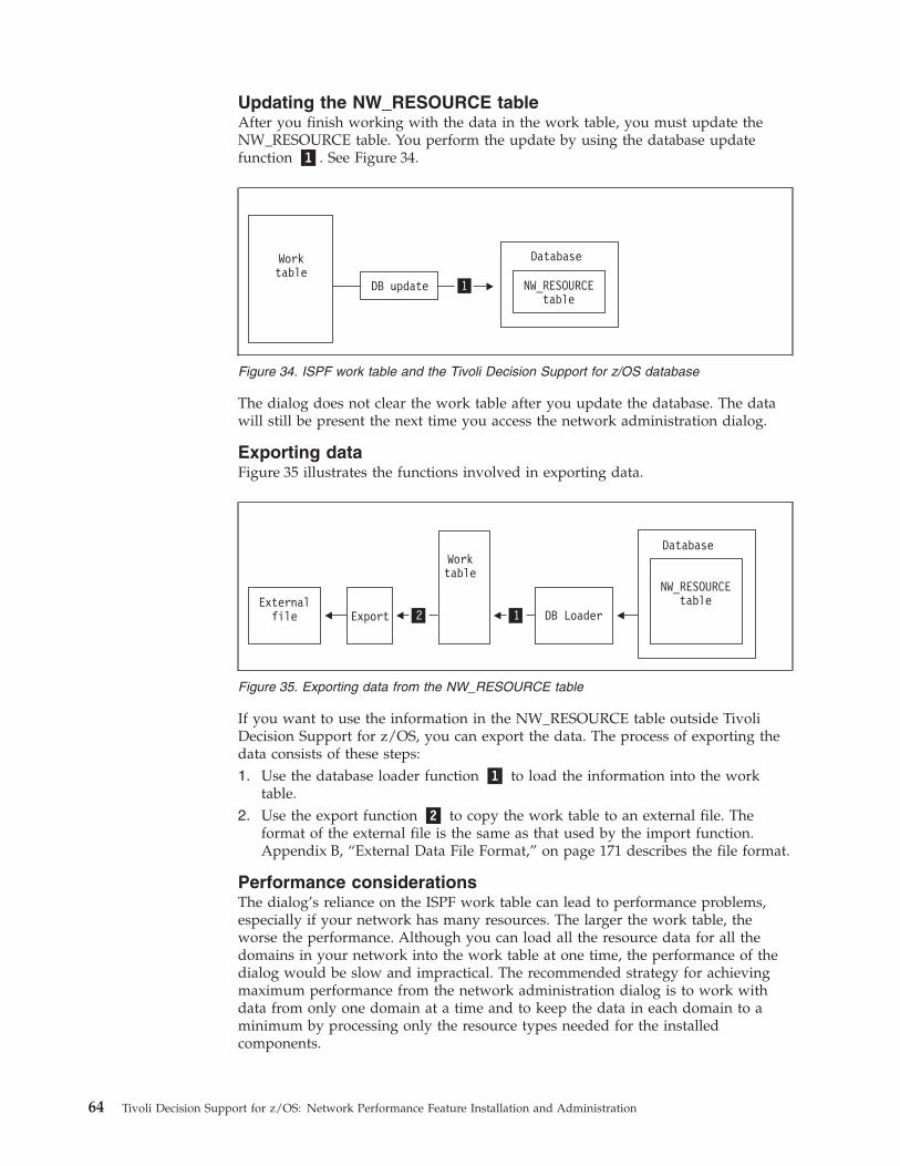
Updating the NW_RESOURCE table
After you finish working with the data in the work table, you must update the
NW_RESOURCE table. You perform the update by using the database update
function �1�. See Figure 34.
The dialog does not clear the work table after you update the database. The data
will still be present the next time you access the network administration dialog.
Exporting data
Figure 35 illustrates the functions involved in exporting data.
If you want to use the information in the NW_RESOURCE table outside Tivoli
Decision Support for z/OS, you can export the data. The process of exporting the
data consists of these steps:
1. Use the database loader function �1� to load the information into the work
table.
2. Use the export function �2� to copy the work table to an external file. The
format of the external file is the same as that used by the import function.
Appendix B, “External Data File Format,” on page 171 describes the file format.
Performance considerations
The dialog’s reliance on the ISPF work table can lead to performance problems,
especially if your network has many resources. The larger the work table, the
worse the performance. Although you can load all the resource data for all the
domains in your network into the work table at one time, the performance of the
dialog would be slow and impractical. The recommended strategy for achieving
maximum performance from the network administration dialog is to work with
data from only one domain at a time and to keep the data in each domain to a
minimum by processing only the resource types needed for the installed
components.
1
Worktable
DB update
Database
NW_RESOURCEtable
Figure 34. ISPF work table and the Tivoli Decision Support for z/OS database
12ExportExternalfile
Worktable
DB Loader
Database
NW_RESOURCEtable
Figure 35. Exporting data from the NW_RESOURCE table
64 Tivoli Decision Support for z/OS: Network Performance Feature Installation and Administration
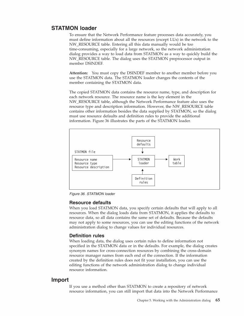
STATMON loader
To ensure that the Network Performance feature processes data accurately, you
must define information about all the resources (except LUs) in the network to the
NW_RESOURCE table. Entering all this data manually would be too
time-consuming, especially for a large network, so the network administration
dialog provides a way to load data from STATMON as a way to quickly build the
NW_RESOURCE table. The dialog uses the STATMON preprocessor output in
member DSINDEF.
Attention: You must copy the DSINDEF member to another member before you
use the STATMON data. The STATMON loader changes the contents of the
member containing the STATMON data.
The copied STATMON data contains the resource name, type, and description for
each network resource. The resource name is the key element in the
NW_RESOURCE table, although the Network Performance feature also uses the
resource type and description information. However, the NW_RESOURCE table
contains other information besides the data supplied by STATMON, so the dialog
must use resource defaults and definition rules to provide the additional
information. Figure 36 illustrates the parts of the STATMON loader.
Resource defaults
When you load STATMON data, you specify certain defaults that will apply to all
resources. When the dialog loads data from STATMON, it applies the defaults to
resource data, so all data contains the same set of defaults. Because the defaults
may not apply to some resources, you can use the editing functions of the network
administration dialog to change values for individual resources.
Definition rules
When loading data, the dialog uses certain rules to define information not
specified in the STATMON data or in the defaults. For example, the dialog creates
synonym names for cross-connection resources by combining the cross-domain
resource manager names from each end of the connection. If the information
created by the definition rules does not fit your installation, you can use the
editing functions of the network administration dialog to change individual
resource information.
Import
If you use a method other than STATMON to create a repository of network
resource information, you can still import that data into the Network Performance
Resourcedefaults
STATMONloader
Resource nameResource typeResource description
STATMON file
Definitionrules
Worktable
Figure 36. STATMON loader
Chapter 5. Working with the Administration dialog 65
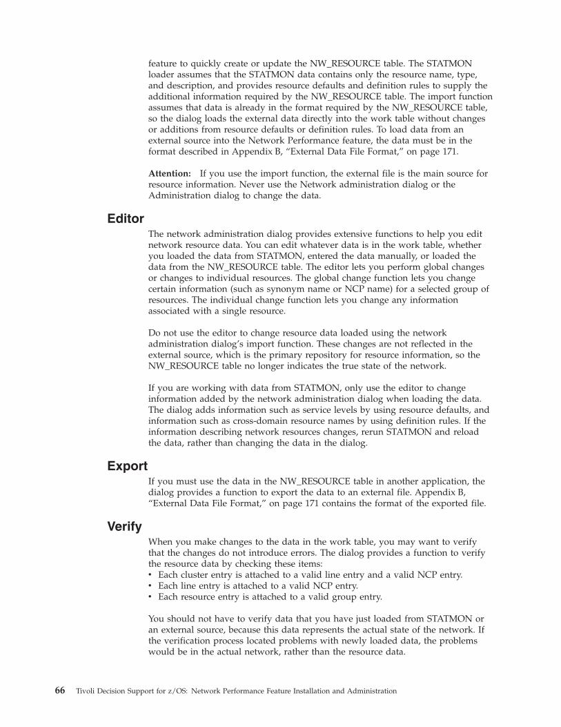
feature to quickly create or update the NW_RESOURCE table. The STATMON
loader assumes that the STATMON data contains only the resource name, type,
and description, and provides resource defaults and definition rules to supply the
additional information required by the NW_RESOURCE table. The import function
assumes that data is already in the format required by the NW_RESOURCE table,
so the dialog loads the external data directly into the work table without changes
or additions from resource defaults or definition rules. To load data from an
external source into the Network Performance feature, the data must be in the
format described in Appendix B, “External Data File Format,” on page 171.
Attention: If you use the import function, the external file is the main source for
resource information. Never use the Network administration dialog or the
Administration dialog to change the data.
Editor
The network administration dialog provides extensive functions to help you edit
network resource data. You can edit whatever data is in the work table, whether
you loaded the data from STATMON, entered the data manually, or loaded the
data from the NW_RESOURCE table. The editor lets you perform global changes
or changes to individual resources. The global change function lets you change
certain information (such as synonym name or NCP name) for a selected group of
resources. The individual change function lets you change any information
associated with a single resource.
Do not use the editor to change resource data loaded using the network
administration dialog’s import function. These changes are not reflected in the
external source, which is the primary repository for resource information, so the
NW_RESOURCE table no longer indicates the true state of the network.
If you are working with data from STATMON, only use the editor to change
information added by the network administration dialog when loading the data.
The dialog adds information such as service levels by using resource defaults, and
information such as cross-domain resource names by using definition rules. If the
information describing network resources changes, rerun STATMON and reload
the data, rather than changing the data in the dialog.
Export
If you must use the data in the NW_RESOURCE table in another application, the
dialog provides a function to export the data to an external file. Appendix B,
“External Data File Format,” on page 171 contains the format of the exported file.
Verify
When you make changes to the data in the work table, you may want to verify
that the changes do not introduce errors. The dialog provides a function to verify
the resource data by checking these items:
v Each cluster entry is attached to a valid line entry and a valid NCP entry.
v Each line entry is attached to a valid NCP entry.
v Each resource entry is attached to a valid group entry.
You should not have to verify data that you have just loaded from STATMON or
an external source, because this data represents the actual state of the network. If
the verification process located problems with newly loaded data, the problems
would be in the actual network, rather than the resource data.
66 Tivoli Decision Support for z/OS: Network Performance Feature Installation and Administration
Database update
After you finish working with the data in the work table, update the
NW_RESOURCE table in the Tivoli Decision Support for z/OS database for the
Network Performance feature so you can use the data. When you load data into
the dialog using the STATMON loader or the import function, the dialog loads the
data into the work table, so you must update the database to load the data into the
NW_RESOURCE table. When you change the data in the NW_RESOURCE table,
the dialog copies the data from the NW_RESOURCE table into the work table, so
you must update the database to load the changed data back into the
NW_RESOURCE table.
Database loader
If you want to use the dialog to edit or verify the data in the NW_RESOURCE
table, you must load the data into the work table. When you load the data into the
work table, the dialog copies the data into the work table and leaves the existing
data in the NW_RESOURCE table intact so the Network Performance feature can
continue to operate. Because editing changes are to the copied data, rather than the
original, you must run the database update function to copy the changed data
from the work table back into the NW_RESOURCE table.
Overview of administration dialog tasks
This section describes the main tasks you can perform with the network
administration dialog. The main function of the network administration dialog is to
maintain the NW_RESOURCE table. The dialog provides two methods for this:
v Use data from STATMON
v Use data from an external source
This section briefly describes the process for working with each type of data. The
sections after this one provide detailed descriptions of the procedures for working
with the dialog.
Administration tasks with STATMON data
The procedure for working with STATMON data is the same regardless of whether
you are working with data from one network domain or several domains. The
procedure for working with STATMON data is:
1. Use the network administration dialog to set the defaults for the STATMON
data.
2. Load the STATMON data into the NW_RESOURCE table. Loading the data
involves:
a. Clearing the work table
b. Loading the STATMON data into the work table
c. Updating the database (NW_RESOURCE table)3. Change the data in the NW_RESOURCE table as needed. This is an ongoing
process. Changing the data in the NW_RESOURCE table involves:
a. Clearing the work table
b. Loading the data from the NW_RESOURCE table into the work table
c. Editing the data
d. Verifying the data
e. Updating the database (NW_RESOURCE table)
Chapter 5. Working with the Administration dialog 67
4. Add new resources to the existing resource data. Depending on the number of
new resources involved, you can either add the new data using the editing
functions of the network administration dialog or load a new copy of the
STATMON data and merge that data with the existing data. While loading new
STATMON data, the dialog compares the resource names in the new and
existing data. If the resource names match, the dialog does not load the data for
that resource. If the dialog finds a resource name in the new STATMON data
that is not in the existing data, the data for that resource is added to the
resource data.
Administration tasks with data from an external source
If you are using data from an external source, this is the procedure for working
with the data:
1. From the external source, create a data set containing the data to be imported
into Tivoli Decision Support for z/OS. The data must be in the format
described in Appendix B, “External Data File Format,” on page 171.
2. Set the resource defaults in the Edit Resource Defaults window. Although the
import function does not use many of these defaults (such as STATMON data
set name), you must specify all the defaults in this window in order to specify
the output data set name. The dialog uses the output data set name when
updating the database, so you must specify this default. The dialog does not
allow you to specify only this default, so you must specify all the defaults.
Attention: If you do not use this approach, you will not be able to load data
from the NW_RESOURCE table, although you will still be able to update the
NW_RESOURCE table.
3. Use the import resource data option to import data from the external source
into the network administration dialog. The dialog does not change the data as
it is being imported.
4. After the resource data is loaded into the NW_RESOURCE table, the Network
Performance feature can begin using the data. Because this data is maintained
in an external file, you must not use the network administration dialog to
change the data in the NW_RESOURCE table.
5. If the network resource data changes, use the import function to import an
updated copy of the external resource data.
6. If you need to back up the resource data or use the data in another application,
use the export function to export a copy of the data in the NW_RESOURCE
table.
Working with STATMON data
If you use data from the STATMON preprocessor, you can use that data in the
NW_RESOURCE table, which ensures that the resource data in Tivoli Decision
Support for z/OS is identical to that defined for VTAM. If your network has more
than one domain, you should work with the data for each domain separately,
rather than loading resource data for the entire network into the work table at
once. Loading data for too many resources into the work table decreases the
performance of the network administration dialog. The basic procedure for
building the NW_RESOURCE table from STATMON data is:
1. Run the STATMON preprocessor.
2. Set the defaults for network resources in the network administration dialog.
3. Load the STATMON data into the dialog work table.
4. Change the resource information if necessary.
68 Tivoli Decision Support for z/OS: Network Performance Feature Installation and Administration
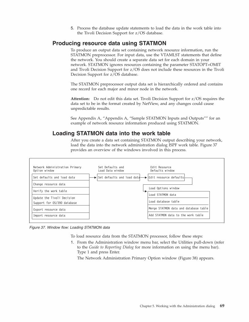
5. Process the database update statements to load the data in the work table into
the Tivoli Decision Support for z/OS database.
Producing resource data using STATMON
To produce an output data set containing network resource information, run the
STATMON preprocessor. For input data, use the VTAMLST statements that define
the network. You should create a separate data set for each domain in your
network. STATMON ignores resources containing the parameter STATOPT=OMIT
and Tivoli Decision Support for z/OS does not include these resources in the Tivoli
Decision Support for z/OS database.
The STATMON preprocessor output data set is hierarchically ordered and contains
one record for each major and minor node in the network.
Attention: Do not edit this data set. Tivoli Decision Support for z/OS requires the
data set to be in the format created by NetView, and any changes could cause
unpredictable results.
See Appendix A, “Appendix A, “Sample STATMON Inputs and Outputs”” for an
example of network resource information produced using STATMON.
Loading STATMON data into the work table
After you create a data set containing STATMON output describing your network,
load the data into the network administration dialog ISPF work table. Figure 37
provides an overview of the windows involved in this process.
To load resource data from the STATMON processor, follow these steps:
1. From the Administration window menu bar, select the Utilities pull-down (refer
to the Guide to Reporting Dialog for more information on using the menu bar).
Type 1 and press Enter.
The Network Administration Primary Option window (Figure 38) appears.
Figure 37. Window flow: Loading STATMON data
Chapter 5. Working with the Administration dialog 69
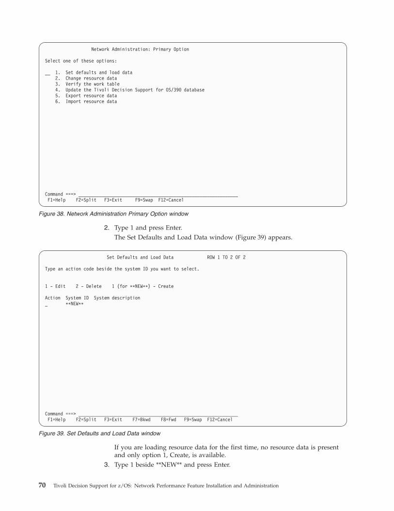
2. Type 1 and press Enter.
The Set Defaults and Load Data window (Figure 39) appears.
If you are loading resource data for the first time, no resource data is present
and only option 1, Create, is available.
3. Type 1 beside **NEW** and press Enter.
Network Administration: Primary Option
Select one of these options:
__ 1. Set defaults and load data
2. Change resource data
3. Verify the work table
4. Update the Tivoli Decision Support for OS/390 database
5. Export resource data
6. Import resource data
Command ===> ______________________________________________________________
F1=Help F2=Split F3=Exit F9=Swap F12=Cancel
Figure 38. Network Administration Primary Option window
Set Defaults and Load Data ROW 1 TO 2 OF 2
Type an action code beside the system ID you want to select.
1 - Edit 2 - Delete 1 (for **NEW**) - Create
Action System ID System description
_ **NEW**
Command ===> ______________________________________________________________
F1=Help F2=Split F3=Exit F7=Bkwd F8=Fwd F9=Swap F12=Cancel
Figure 39. Set Defaults and Load Data window
70 Tivoli Decision Support for z/OS: Network Performance Feature Installation and Administration
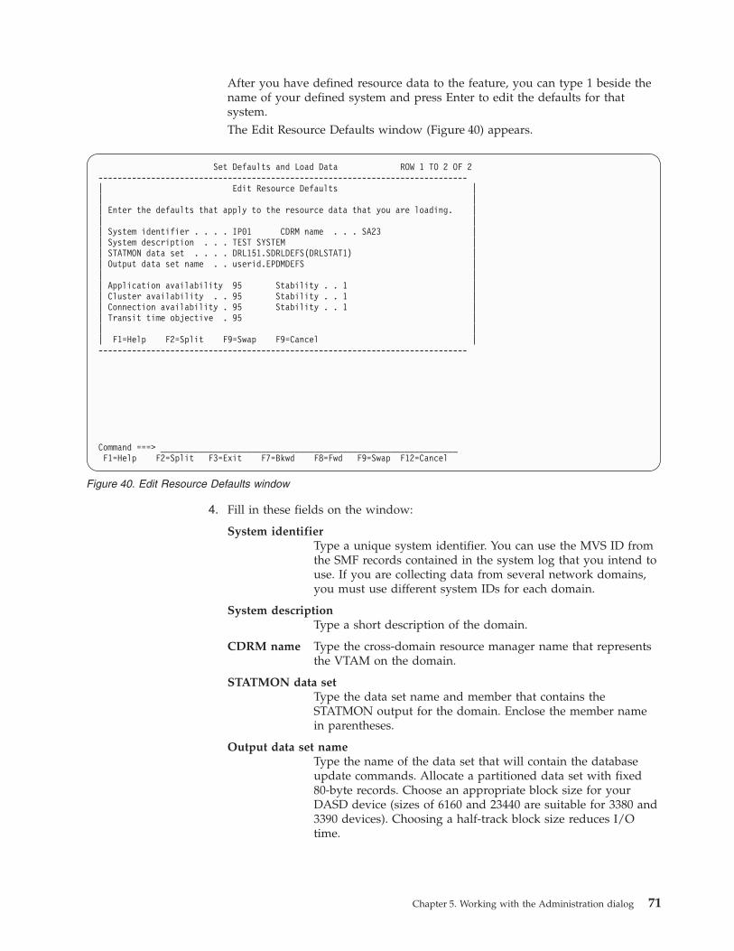
After you have defined resource data to the feature, you can type 1 beside the
name of your defined system and press Enter to edit the defaults for that
system.
The Edit Resource Defaults window (Figure 40) appears.
4. Fill in these fields on the window:
System identifier
Type a unique system identifier. You can use the MVS ID from
the SMF records contained in the system log that you intend to
use. If you are collecting data from several network domains,
you must use different system IDs for each domain.
System description
Type a short description of the domain.
CDRM name Type the cross-domain resource manager name that represents
the VTAM on the domain.
STATMON data set
Type the data set name and member that contains the
STATMON output for the domain. Enclose the member name
in parentheses.
Output data set name
Type the name of the data set that will contain the database
update commands. Allocate a partitioned data set with fixed
80-byte records. Choose an appropriate block size for your
DASD device (sizes of 6160 and 23440 are suitable for 3380 and
3390 devices). Choosing a half-track block size reduces I/O
time.
Set Defaults and Load Data ROW 1 TO 2 OF 2
-----------------------------------------------------------------------------
| Edit Resource Defaults |
| |
| Enter the defaults that apply to the resource data that you are loading. |
| |
| System identifier . . . . IP01 CDRM name . . . SA23 |
| System description . . . TEST SYSTEM |
| STATMON data set . . . . DRL151.SDRLDEFS(DRLSTAT1) |
| Output data set name . . userid.EPDMDEFS |
| |
| Application availability 95 Stability . . 1 |
| Cluster availability . . 95 Stability . . 1 |
| Connection availability . 95 Stability . . 1 |
| Transit time objective . 95 |
| |
| F1=Help F2=Split F9=Swap F9=Cancel |
-----------------------------------------------------------------------------
Command ===> ______________________________________________________________
F1=Help F2=Split F3=Exit F7=Bkwd F8=Fwd F9=Swap F12=Cancel
Figure 40. Edit Resource Defaults window
Chapter 5. Working with the Administration dialog 71
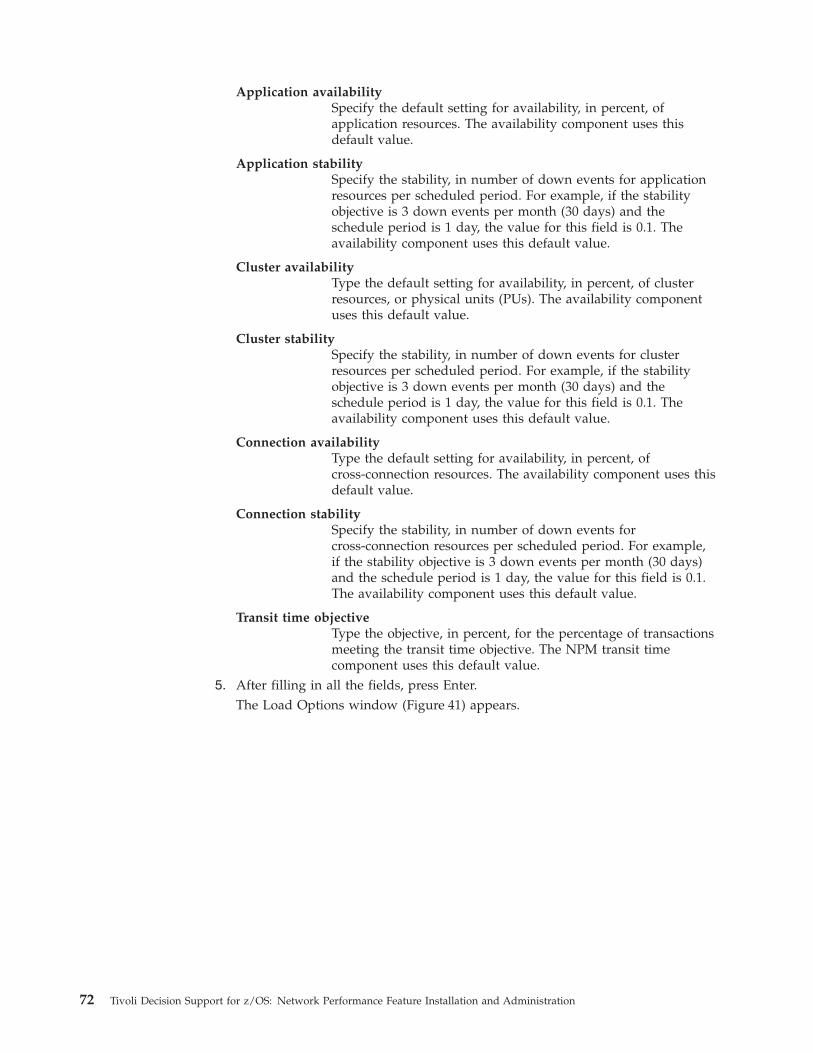
Application availability
Specify the default setting for availability, in percent, of
application resources. The availability component uses this
default value.
Application stability
Specify the stability, in number of down events for application
resources per scheduled period. For example, if the stability
objective is 3 down events per month (30 days) and the
schedule period is 1 day, the value for this field is 0.1. The
availability component uses this default value.
Cluster availability
Type the default setting for availability, in percent, of cluster
resources, or physical units (PUs). The availability component
uses this default value.
Cluster stability
Specify the stability, in number of down events for cluster
resources per scheduled period. For example, if the stability
objective is 3 down events per month (30 days) and the
schedule period is 1 day, the value for this field is 0.1. The
availability component uses this default value.
Connection availability
Type the default setting for availability, in percent, of
cross-connection resources. The availability component uses this
default value.
Connection stability
Specify the stability, in number of down events for
cross-connection resources per scheduled period. For example,
if the stability objective is 3 down events per month (30 days)
and the schedule period is 1 day, the value for this field is 0.1.
The availability component uses this default value.
Transit time objective
Type the objective, in percent, for the percentage of transactions
meeting the transit time objective. The NPM transit time
component uses this default value.5. After filling in all the fields, press Enter.
The Load Options window (Figure 41) appears.
72 Tivoli Decision Support for z/OS: Network Performance Feature Installation and Administration
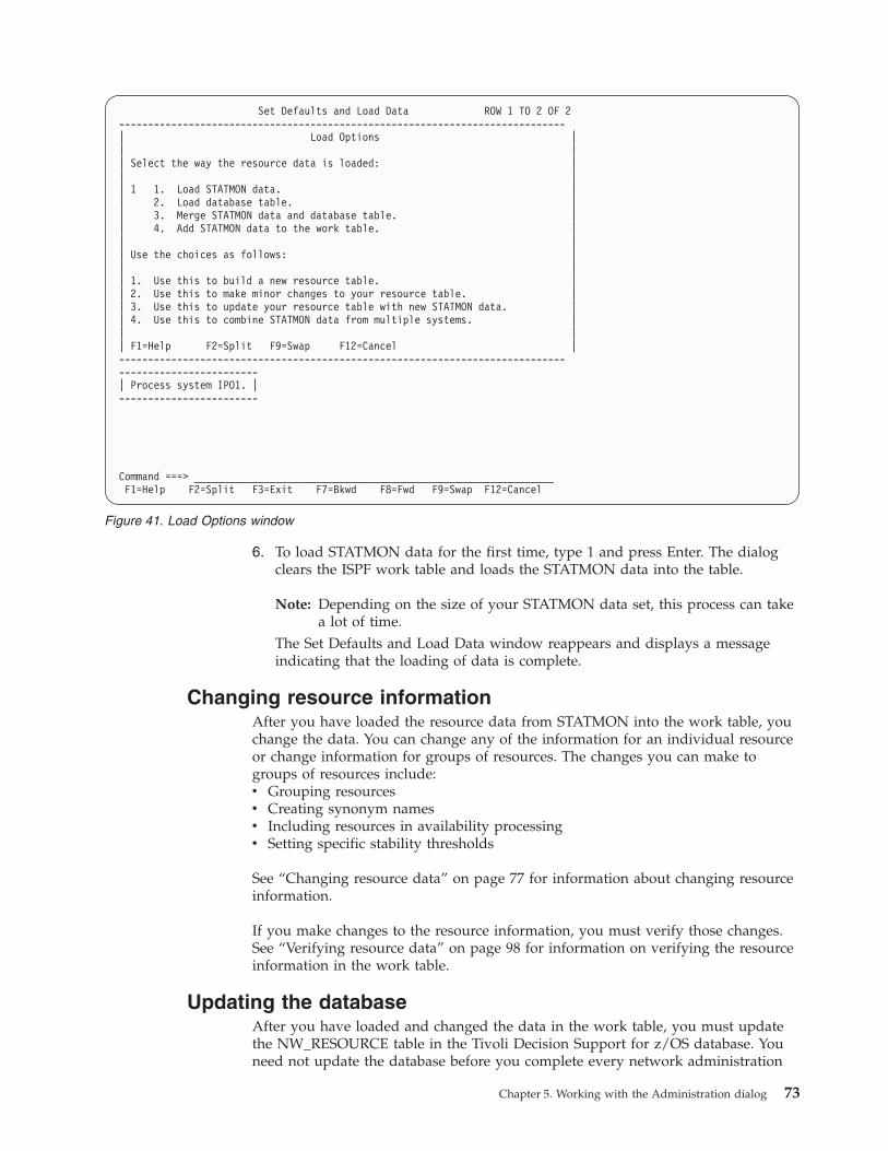
6. To load STATMON data for the first time, type 1 and press Enter. The dialog
clears the ISPF work table and loads the STATMON data into the table.
Note: Depending on the size of your STATMON data set, this process can take
a lot of time.
The Set Defaults and Load Data window reappears and displays a message
indicating that the loading of data is complete.
Changing resource information
After you have loaded the resource data from STATMON into the work table, you
change the data. You can change any of the information for an individual resource
or change information for groups of resources. The changes you can make to
groups of resources include:
v Grouping resources
v Creating synonym names
v Including resources in availability processing
v Setting specific stability thresholds
See “Changing resource data” on page 77 for information about changing resource
information.
If you make changes to the resource information, you must verify those changes.
See “Verifying resource data” on page 98 for information on verifying the resource
information in the work table.
Updating the database
After you have loaded and changed the data in the work table, you must update
the NW_RESOURCE table in the Tivoli Decision Support for z/OS database. You
need not update the database before you complete every network administration
Set Defaults and Load Data ROW 1 TO 2 OF 2
-----------------------------------------------------------------------------
| Load Options |
| |
| Select the way the resource data is loaded: |
| |
| 1 1. Load STATMON data. |
| 2. Load database table. |
| 3. Merge STATMON data and database table. |
| 4. Add STATMON data to the work table. |
| |
| Use the choices as follows: |
| |
| 1. Use this to build a new resource table. |
| 2. Use this to make minor changes to your resource table. |
| 3. Use this to update your resource table with new STATMON data. |
| 4. Use this to combine STATMON data from multiple systems. |
| |
| F1=Help F2=Split F9=Swap F12=Cancel |
-----------------------------------------------------------------------------
------------------------
| Process system IPO1. |
------------------------
Command ===> ______________________________________________________________
F1=Help F2=Split F3=Exit F7=Bkwd F8=Fwd F9=Swap F12=Cancel
Figure 41. Load Options window
Chapter 5. Working with the Administration dialog 73
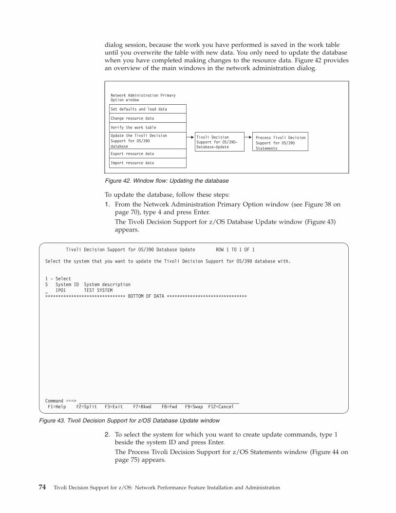
dialog session, because the work you have performed is saved in the work table
until you overwrite the table with new data. You only need to update the database
when you have completed making changes to the resource data. Figure 42 provides
an overview of the main windows in the network administration dialog.
To update the database, follow these steps:
1. From the Network Administration Primary Option window (see Figure 38 on
page 70), type 4 and press Enter.
The Tivoli Decision Support for z/OS Database Update window (Figure 43)
appears.
2. To select the system for which you want to create update commands, type 1
beside the system ID and press Enter.
The Process Tivoli Decision Support for z/OS Statements window (Figure 44 on
page 75) appears.
Figure 42. Window flow: Updating the database
Tivoli Decision Support for OS/390 Database Update ROW 1 TO 1 OF 1
Select the system that you want to update the Tivoli Decision Support for OS/390 database with.
1 - Select
S System ID System description
_ IPO1 TEST SYSTEM
******************************* BOTTOM OF DATA *******************************
Command ===> ______________________________________________________________
F1=Help F2=Split F3=Exit F7=Bkwd F8=Fwd F9=Swap F12=Cancel
Figure 43. Tivoli Decision Support for z/OS Database Update window
74 Tivoli Decision Support for z/OS: Network Performance Feature Installation and Administration
3. Type 1 in the Type of statements field and press F5 (Execute).
Tivoli Decision Support for z/OS processes the database update commands and
displays messages indicating whether the commands were executed
successfully.
4. Press F3 to return to the Tivoli Decision Support for z/OS Statements window.
5. Press F12 to return to the Tivoli Decision Support for z/OS Database Update
window.
Loading data from multiple domains into NW_RESOURCE
If your network contains more than one domain, you can still use STATMON to
load the network resource data into the NW_RESOURCE table. Run STATMON
once for each domain in your network. Use the VTAMLST statements for that
domain as input data, and write the output to a different data set or member for
each domain.
It is recommended that, for performance reasons, you work with only one domain
at a time. Update the NW_RESOURCE table and clear the work table before
loading the STATMON (or external source) data for the next domain.
To use STATMON data from multiple domains, load the data from each domain
separately, using a different system ID to identify the data from each domain.
Figure 45 on page 76 illustrates this method, which is described in the remainder
of this section.
Tivoli Decision Support for OS/390 Reporter Database Update ROW 1 TO 1 OF 1
------------------------------------------------------------------------------
| Process Tivoli Decision Support for OS/390 Reporter Statements |
| |
| Type the data set name. Then press Enter to edit the statements. |
| |
| Input data set name userid.EPDMDEFS |
| |
| Type of statements . . . . __ 1. Log collector |
| 2. Report definition |
| |
| Show input statements . . . 2 1. Yes |
| 2. No |
| |
| Trace SQL calls . . . . . . 2 1. Yes |
| 2. No |
| |
| F1=Help F5=Execute F12=Cancel |
------------------------------------------------------------------------------
------------------------------
| 685 records were processed.|
------------------------------
Command ===> ______________________________________________________________
F1=Help F2=Split F3=Exit F7=Bkwd F8=Fwd F9=Swap F12=Cancel
Figure 44. Process Tivoli Decision Support for z/OS Statements window
Chapter 5. Working with the Administration dialog 75
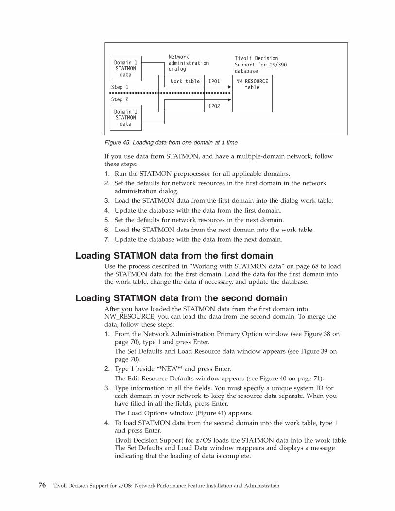
If you use data from STATMON, and have a multiple-domain network, follow
these steps:
1. Run the STATMON preprocessor for all applicable domains.
2. Set the defaults for network resources in the first domain in the network
administration dialog.
3. Load the STATMON data from the first domain into the dialog work table.
4. Update the database with the data from the first domain.
5. Set the defaults for network resources in the next domain.
6. Load the STATMON data from the next domain into the work table.
7. Update the database with the data from the next domain.
Loading STATMON data from the first domain
Use the process described in “Working with STATMON data” on page 68 to load
the STATMON data for the first domain. Load the data for the first domain into
the work table, change the data if necessary, and update the database.
Loading STATMON data from the second domain
After you have loaded the STATMON data from the first domain into
NW_RESOURCE, you can load the data from the second domain. To merge the
data, follow these steps:
1. From the Network Administration Primary Option window (see Figure 38 on
page 70), type 1 and press Enter.
The Set Defaults and Load Resource data window appears (see Figure 39 on
page 70).
2. Type 1 beside **NEW** and press Enter.
The Edit Resource Defaults window appears (see Figure 40 on page 71).
3. Type information in all the fields. You must specify a unique system ID for
each domain in your network to keep the resource data separate. When you
have filled in all the fields, press Enter.
The Load Options window (Figure 41) appears.
4. To load STATMON data from the second domain into the work table, type 1
and press Enter.
Tivoli Decision Support for z/OS loads the STATMON data into the work table.
The Set Defaults and Load Data window reappears and displays a message
indicating that the loading of data is complete.
Figure 45. Loading data from one domain at a time
76 Tivoli Decision Support for z/OS: Network Performance Feature Installation and Administration
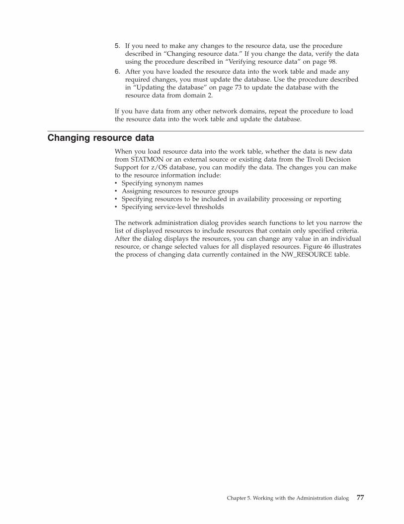
5. If you need to make any changes to the resource data, use the procedure
described in “Changing resource data.” If you change the data, verify the data
using the procedure described in “Verifying resource data” on page 98.
6. After you have loaded the resource data into the work table and made any
required changes, you must update the database. Use the procedure described
in “Updating the database” on page 73 to update the database with the
resource data from domain 2.
If you have data from any other network domains, repeat the procedure to load
the resource data into the work table and update the database.
Changing resource data
When you load resource data into the work table, whether the data is new data
from STATMON or an external source or existing data from the Tivoli Decision
Support for z/OS database, you can modify the data. The changes you can make
to the resource information include:
v Specifying synonym names
v Assigning resources to resource groups
v Specifying resources to be included in availability processing or reporting
v Specifying service-level thresholds
The network administration dialog provides search functions to let you narrow the
list of displayed resources to include resources that contain only specified criteria.
After the dialog displays the resources, you can change any value in an individual
resource, or change selected values for all displayed resources. Figure 46 illustrates
the process of changing data currently contained in the NW_RESOURCE table.
Chapter 5. Working with the Administration dialog 77
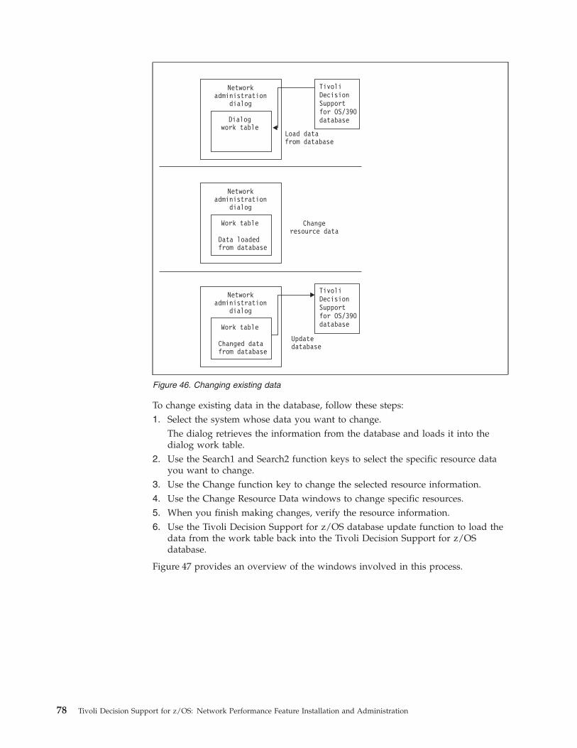
To change existing data in the database, follow these steps:
1. Select the system whose data you want to change.
The dialog retrieves the information from the database and loads it into the
dialog work table.
2. Use the Search1 and Search2 function keys to select the specific resource data
you want to change.
3. Use the Change function key to change the selected resource information.
4. Use the Change Resource Data windows to change specific resources.
5. When you finish making changes, verify the resource information.
6. Use the Tivoli Decision Support for z/OS database update function to load the
data from the work table back into the Tivoli Decision Support for z/OS
database.
Figure 47 provides an overview of the windows involved in this process.
Figure 46. Changing existing data
78 Tivoli Decision Support for z/OS: Network Performance Feature Installation and Administration
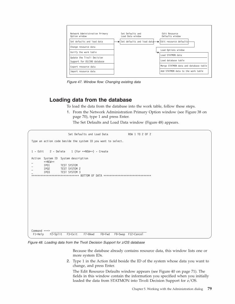
Loading data from the database
To load the data from the database into the work table, follow these steps.
1. From the Network Administration Primary Option window (see Figure 38 on
page 70), type 1 and press Enter.
The Set Defaults and Load Data window (Figure 48) appears.
Because the database already contains resource data, this window lists one or
more system IDs.
2. Type 1 in the Action field beside the ID of the system whose data you want to
change, and press Enter.
The Edit Resource Defaults window appears (see Figure 40 on page 71). The
fields in this window contain the information you specified when you initially
loaded the data from STATMON into Tivoli Decision Support for z/OS.
Figure 47. Window flow: Changing existing data
Set Defaults and Load Data ROW 1 TO 2 OF 2
Type an action code beside the system ID you want to select.
1 - Edit 2 - Delete 1 (for **NEW**) - Create
Action System ID System description
_ **NEW**
_ IPO1 TEST SYSTEM
_ IPO2 TEST SYSTEM 2
_ IPO3 TEST SYSTEM 3
******************************* BOTTOM OF DATA *******************************
Command ===> ______________________________________________________________
F1=Help F2=Split F3=Exit F7=Bkwd F8=Fwd F9=Swap F12=Cancel
Figure 48. Loading data from the Tivoli Decision Support for z/OS database
Chapter 5. Working with the Administration dialog 79
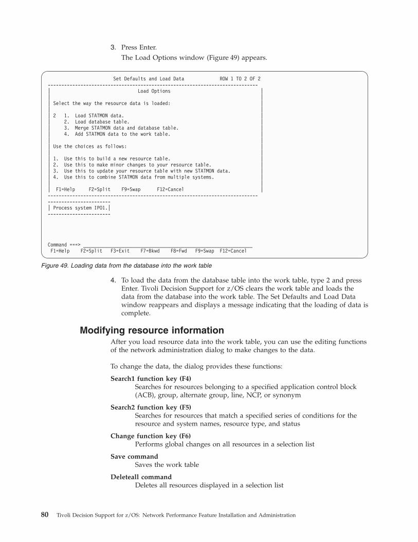
3. Press Enter.
The Load Options window (Figure 49) appears.
4. To load the data from the database table into the work table, type 2 and press
Enter. Tivoli Decision Support for z/OS clears the work table and loads the
data from the database into the work table. The Set Defaults and Load Data
window reappears and displays a message indicating that the loading of data is
complete.
Modifying resource information
After you load resource data into the work table, you can use the editing functions
of the network administration dialog to make changes to the data.
To change the data, the dialog provides these functions:
Search1 function key (F4)
Searches for resources belonging to a specified application control block
(ACB), group, alternate group, line, NCP, or synonym
Search2 function key (F5)
Searches for resources that match a specified series of conditions for the
resource and system names, resource type, and status
Change function key (F6)
Performs global changes on all resources in a selection list
Save command
Saves the work table
Deleteall command
Deletes all resources displayed in a selection list
Set Defaults and Load Data ROW 1 TO 2 OF 2
-----------------------------------------------------------------------------
| Load Options |
| |
| Select the way the resource data is loaded: |
| |
| 2 1. Load STATMON data. |
| 2. Load database table. |
| 3. Merge STATMON data and database table. |
| 4. Add STATMON data to the work table. |
| |
| Use the choices as follows: |
| |
| 1. Use this to build a new resource table. |
| 2. Use this to make minor changes to your resource table. |
| 3. Use this to update your resource table with new STATMON data. |
| 4. Use this to combine STATMON data from multiple systems. |
| |
| F1=Help F2=Split F9=Swap F12=Cancel |
-----------------------------------------------------------------------------
-----------------------
| Process system IPO1.|
-----------------------
Command ===> ______________________________________________________________
F1=Help F2=Split F3=Exit F7=Bkwd F8=Fwd F9=Swap F12=Cancel
Figure 49. Loading data from the database into the work table
80 Tivoli Decision Support for z/OS: Network Performance Feature Installation and Administration
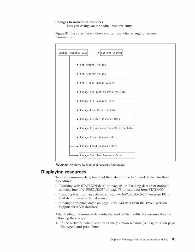
Changes to individual resources
Lets you change an individual resource entry
Figure 50 illustrates the windows you can use when changing resource
information.
Displaying resources
To modify resource data, first load the data into the ISPF work table. Use these
procedures:
v “Working with STATMON data” on page 68 or “Loading data from multiple
domains into NW_RESOURCE” on page 75 to load data from STATMON
v “Loading data from an external source into NW_RESOURCE” on page 102 to
load data from an external source
v “Changing resource data” on page 77 to load data from the Tivoli Decision
Support for z/OS database
After loading the resource data into the work table, modify the resource data by
following these steps:
1. In the Network Administration Primary Option window (see Figure 38 on page
70), type 2 and press Enter.
Figure 50. Windows for changing resource information
Chapter 5. Working with the Administration dialog 81
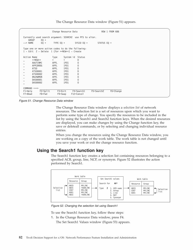
The Change Resource Data window (Figure 51) appears.
The Change Resource Data window displays a selection list of network
resources. The selection list is a set of resources upon which you want to
perform some type of change. You specify the resources to be included in the
list by using the Search1 and Search2 function keys. When the desired resources
are displayed, you can make changes by using the Change function key, the
save or deleteall commands, or by selecting and changing individual resource
entries.
When you change the resources using the Change Resource Data window, you
are working on a copy of the work table. The work table is not changed until
you save your work or exit the change resource function.
Using the Search1 function key
The Search1 function key creates a selection list containing resources belonging to a
specified ACB, group, line, NCP, or synonym. Figure 52 illustrates the action
performed by Search1.
To use the Search1 function key, follow these steps:
1. In the Change Resource Data window, press F4.
The Set Search1 Values window (Figure 53) appears.
Change Resource Data ROW 1 FROM 686
Currently used search argument: SEARCH2 use PF5 to alter.
GROUP EQ *
--> NAME EQ * TYPE EQ * SYSID EQ * STATUS EQ *
Type one or more action codes to do the following:
1 - Edit 2 - Delete 1 (for **NEW**) - Create
Action Name Type System id Status
_ **NEW** * * D
_ AAUTCNMI APPL IPO1 O
_ APPCBRDG APPL IPO1 O
_ ATSO APPL IPO1 D
_ ATSO0001 APPL IPO1 D
_ ATSO0002 APPL IPO1 D
_ BNJHWMON APPL IPO1 O
_ DAS00001 APPL IPO1 O
_ DAS00002 APPL IPO1 O
COMMAND ===> _________________________________________________________________
F1=Help F2=Split F3=Exit F4=Search1 F5=Search2 F6=Change
F7=Bkwd F8=Fwd F9=Swap F12=Cancel
Figure 51. Change Resource Data window
Work table
ResourceResource
Work tableSet Search1 values
1. ACB name2. Group3. Line4. NCP5. Synonym
MY*
Type
Search for
2Selectionlist Selection
list
ABCDABCECDEFA001ABCE
ABCDCDEFA001
MYLINEYOURLINEMYLINEMYLINEYOURLINE
MYLINEMYLINEMYLINE
GroupGroup
Figure 52. Changing the selection list using Search1
82 Tivoli Decision Support for z/OS: Network Performance Feature Installation and Administration
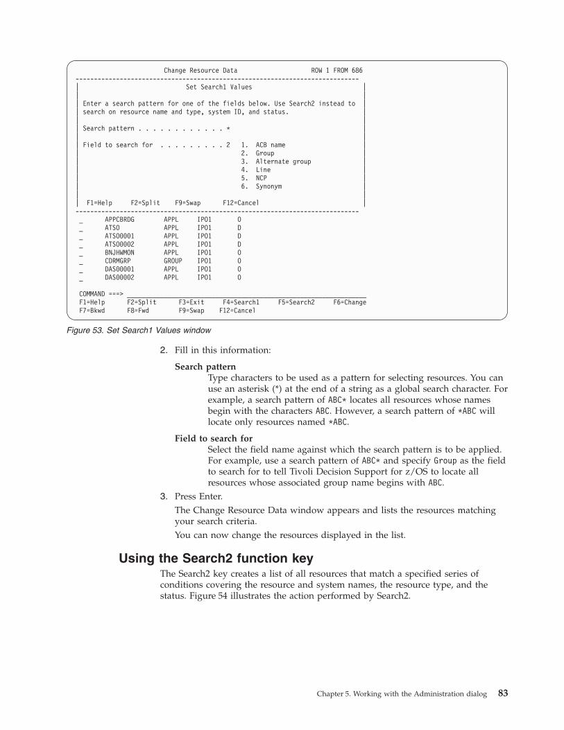
2. Fill in this information:
Search pattern
Type characters to be used as a pattern for selecting resources. You can
use an asterisk (*) at the end of a string as a global search character. For
example, a search pattern of ABC* locates all resources whose names
begin with the characters ABC. However, a search pattern of *ABC will
locate only resources named *ABC.
Field to search for
Select the field name against which the search pattern is to be applied.
For example, use a search pattern of ABC* and specify Group as the field
to search for to tell Tivoli Decision Support for z/OS to locate all
resources whose associated group name begins with ABC.3. Press Enter.
The Change Resource Data window appears and lists the resources matching
your search criteria.
You can now change the resources displayed in the list.
Using the Search2 function key
The Search2 key creates a list of all resources that match a specified series of
conditions covering the resource and system names, the resource type, and the
status. Figure 54 illustrates the action performed by Search2.
Change Resource Data ROW 1 FROM 686
-----------------------------------------------------------------------------
| Set Search1 Values |
| |
| Enter a search pattern for one of the fields below. Use Search2 instead to |
| search on resource name and type, system ID, and status. |
| |
| Search pattern . . . . . . . . . . . . * |
| |
| Field to search for . . . . . . . . . 2 1. ACB name |
| 2. Group |
| 3. Alternate group |
| 4. Line |
| 5. NCP |
| 6. Synonym |
| |
| F1=Help F2=Split F9=Swap F12=Cancel |
-----------------------------------------------------------------------------
_ APPCBRDG APPL IPO1 O
_ ATSO APPL IPO1 D
_ ATSO0001 APPL IPO1 D
_ ATSO0002 APPL IPO1 D
_ BNJHWMON APPL IPO1 O
_ CDRMGRP GROUP IPO1 O
_ DAS00001 APPL IPO1 O
_ DAS00002 APPL IPO1 O
COMMAND ===> _________________________________________________________________
F1=Help F2=Split F3=Exit F4=Search1 F5=Search2 F6=Change
F7=Bkwd F8=Fwd F9=Swap F12=Cancel
Figure 53. Set Search1 Values window
Chapter 5. Working with the Administration dialog 83
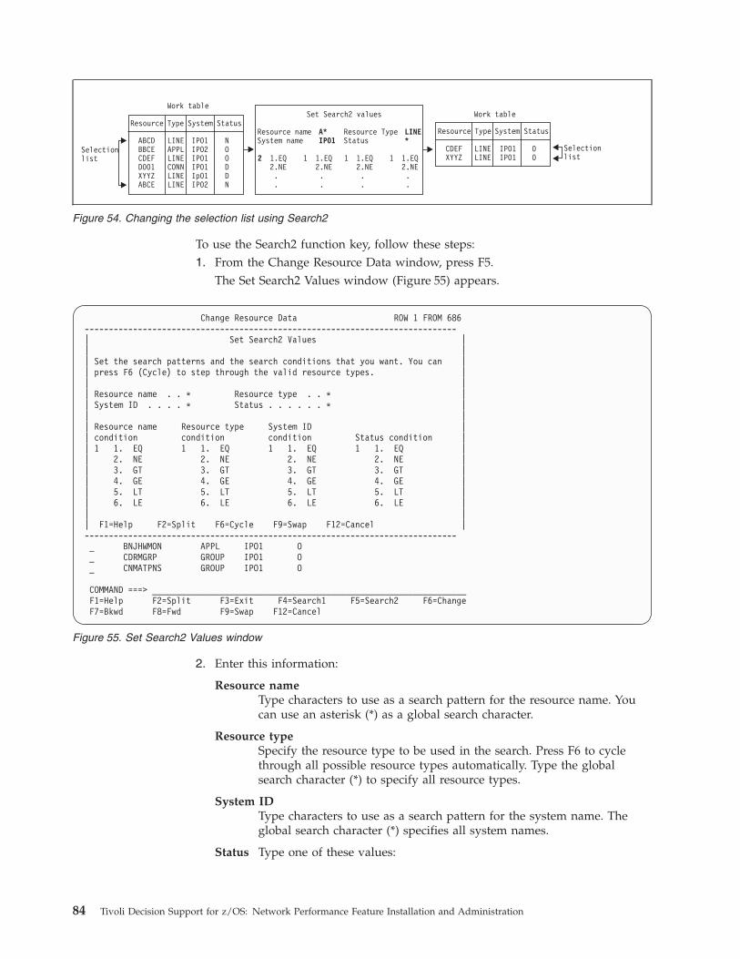
To use the Search2 function key, follow these steps:
1. From the Change Resource Data window, press F5.
The Set Search2 Values window (Figure 55) appears.
2. Enter this information:
Resource name
Type characters to use as a search pattern for the resource name. You
can use an asterisk (*) as a global search character.
Resource type
Specify the resource type to be used in the search. Press F6 to cycle
through all possible resource types automatically. Type the global
search character (*) to specify all resource types.
System ID
Type characters to use as a search pattern for the system name. The
global search character (*) specifies all system names.
Status Type one of these values:
Figure 54. Changing the selection list using Search2
Change Resource Data ROW 1 FROM 686
-----------------------------------------------------------------------------
| Set Search2 Values |
| |
| Set the search patterns and the search conditions that you want. You can |
| press F6 (Cycle) to step through the valid resource types. |
| |
| Resource name . . * Resource type . . * |
| System ID . . . . * Status . . . . . . * |
| |
| Resource name Resource type System ID |
| condition condition condition Status condition |
| 1 1. EQ 1 1. EQ 1 1. EQ 1 1. EQ |
| 2. NE 2. NE 2. NE 2. NE |
| 3. GT 3. GT 3. GT 3. GT |
| 4. GE 4. GE 4. GE 4. GE |
| 5. LT 5. LT 5. LT 5. LT |
| 6. LE 6. LE 6. LE 6. LE |
| |
| F1=Help F2=Split F6=Cycle F9=Swap F12=Cancel |
-----------------------------------------------------------------------------
_ BNJHWMON APPL IPO1 O
_ CDRMGRP GROUP IPO1 O
_ CNMATPNS GROUP IPO1 O
COMMAND ===> _________________________________________________________________
F1=Help F2=Split F3=Exit F4=Search1 F5=Search2 F6=Change
F7=Bkwd F8=Fwd F9=Swap F12=Cancel
Figure 55. Set Search2 Values window
84 Tivoli Decision Support for z/OS: Network Performance Feature Installation and Administration

N Select resources loaded from STATMON that have not been
added to the database or resources manually added to the work
table.
O Select resources loaded from STATMON or an external database
that have been added to the database.
D Select resources present in the Tivoli Decision Support for z/OS
database but not in the STATMON or external data.
* Any status.
This field is only meaningful if you have added STATMON data to
data already in the work table.
Condition fields
This category includes these fields: resource name condition, resource
type condition, system condition, and status condition. These fields
specify how to use the search pattern entered in the corresponding
field. The possible values are:
EQ Equal to. Display names that match the search pattern.
NE Not equal to. Display names that do not match the search
pattern.
GT Greater than. Display names that are alphabetically or
numerically higher than the search pattern. For example,
specifying GT with a search pattern of DB displays all names
beginning with DBA through Z.
GE Greater than or equal to. Display names that match the search
pattern or are alphabetically or numerically higher. For
example, specifying GE with a search pattern of JB displays all
names beginning with JB through Z.
LT Less than. Display names that are alphabetically or numerically
lower than the search pattern. For example, specifying LT with
a search pattern of DB displays all names beginning with A
through DA.
LE Less than or equal to. Display names that match the search
pattern or are alphabetically or numerically lower. For example,
specifying LE with a search pattern of JB displays all names
beginning with A through JB.3. Press Enter.
The Change Resource Data window reappears and displays the resources that
meet your search criteria.
You can now change the resources displayed in the list.
Using the Change function key
The Change function key lets you make global changes to all the resources
contained in the current selection list. To modify the resources displayed in the
selection list, use the Search1 or Search2 function keys. See “Using the Search1
function key” on page 82 for information on the Search1 key and “Using the
Search2 function key” on page 83 for information on the Search2 key.
To use the Change function key, follow these steps:
1. In the Change Resource Data window, press F6.
Chapter 5. Working with the Administration dialog 85
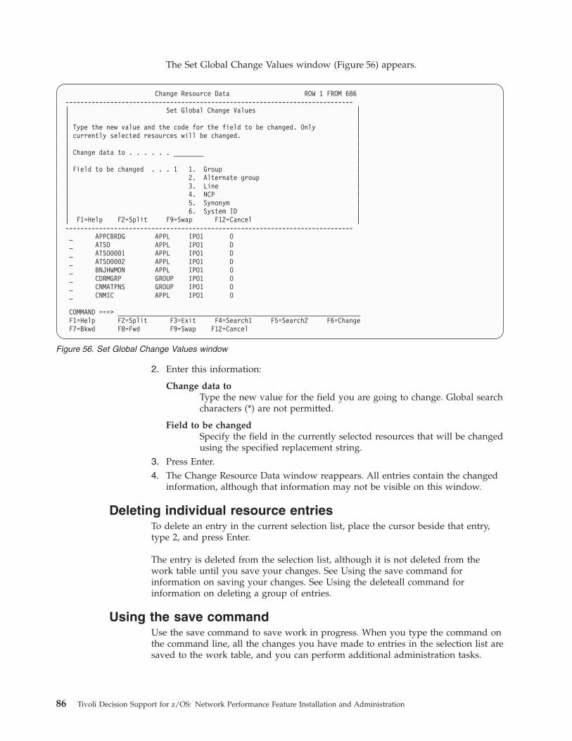
The Set Global Change Values window (Figure 56) appears.
2. Enter this information:
Change data to
Type the new value for the field you are going to change. Global search
characters (*) are not permitted.
Field to be changed
Specify the field in the currently selected resources that will be changed
using the specified replacement string.
3. Press Enter.
4. The Change Resource Data window reappears. All entries contain the changed
information, although that information may not be visible on this window.
Deleting individual resource entries
To delete an entry in the current selection list, place the cursor beside that entry,
type 2, and press Enter.
The entry is deleted from the selection list, although it is not deleted from the
work table until you save your changes. See Using the save command for
information on saving your changes. See Using the deleteall command for
information on deleting a group of entries.
Using the save command
Use the save command to save work in progress. When you type the command on
the command line, all the changes you have made to entries in the selection list are
saved to the work table, and you can perform additional administration tasks.
Change Resource Data ROW 1 FROM 686
-----------------------------------------------------------------------------
| Set Global Change Values |
| |
| Type the new value and the code for the field to be changed. Only |
| currently selected resources will be changed. |
| |
| Change data to . . . . . . ________ |
| |
| Field to be changed . . . 1 1. Group |
| 2. Alternate group |
| 3. Line |
| 4. NCP |
| 5. Synonym |
| 6. System ID |
| F1=Help F2=Split F9=Swap F12=Cancel |
-----------------------------------------------------------------------------
_ APPCBRDG APPL IPO1 O
_ ATSO APPL IPO1 D
_ ATSO0001 APPL IPO1 D
_ ATSO0002 APPL IPO1 D
_ BNJHWMON APPL IPO1 O
_ CDRMGRP GROUP IPO1 O
_ CNMATPNS GROUP IPO1 O
_ CNMIC APPL IPO1 O
COMMAND ===> _________________________________________________________________
F1=Help F2=Split F3=Exit F4=Search1 F5=Search2 F6=Change
F7=Bkwd F8=Fwd F9=Swap F12=Cancel
Figure 56. Set Global Change Values window
86 Tivoli Decision Support for z/OS: Network Performance Feature Installation and Administration
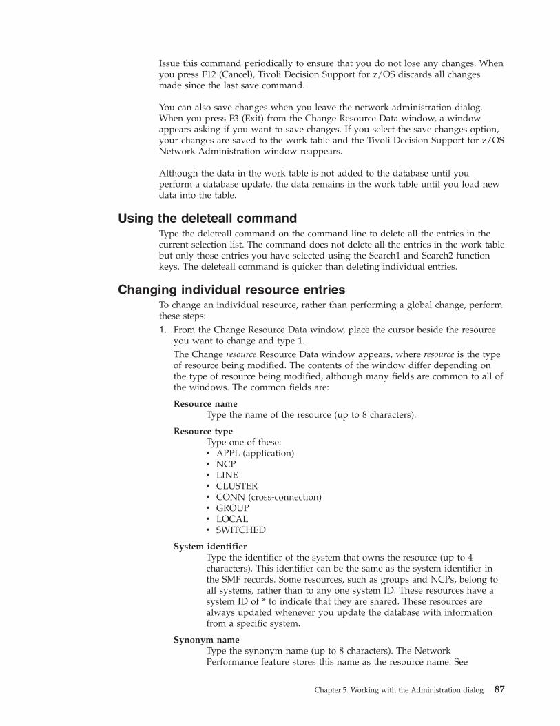
Issue this command periodically to ensure that you do not lose any changes. When
you press F12 (Cancel), Tivoli Decision Support for z/OS discards all changes
made since the last save command.
You can also save changes when you leave the network administration dialog.
When you press F3 (Exit) from the Change Resource Data window, a window
appears asking if you want to save changes. If you select the save changes option,
your changes are saved to the work table and the Tivoli Decision Support for z/OS
Network Administration window reappears.
Although the data in the work table is not added to the database until you
perform a database update, the data remains in the work table until you load new
data into the table.
Using the deleteall command
Type the deleteall command on the command line to delete all the entries in the
current selection list. The command does not delete all the entries in the work table
but only those entries you have selected using the Search1 and Search2 function
keys. The deleteall command is quicker than deleting individual entries.
Changing individual resource entries
To change an individual resource, rather than performing a global change, perform
these steps:
1. From the Change Resource Data window, place the cursor beside the resource
you want to change and type 1.
The Change resource Resource Data window appears, where resource is the type
of resource being modified. The contents of the window differ depending on
the type of resource being modified, although many fields are common to all of
the windows. The common fields are:
Resource name
Type the name of the resource (up to 8 characters).
Resource type
Type one of these:
v APPL (application)
v NCP
v LINE
v CLUSTER
v CONN (cross-connection)
v GROUP
v LOCAL
v SWITCHED
System identifier
Type the identifier of the system that owns the resource (up to 4
characters). This identifier can be the same as the system identifier in
the SMF records. Some resources, such as groups and NCPs, belong to
all systems, rather than to any one system ID. These resources have a
system ID of * to indicate that they are shared. These resources are
always updated whenever you update the database with information
from a specific system.
Synonym name
Type the synonym name (up to 8 characters). The Network
Performance feature stores this name as the resource name. See
Chapter 5. Working with the Administration dialog 87
“Changing the NCP resource data” on page 116, “Changing application
resources environment data” on page 122, and “Changing the
cross-connection resource environment data” on page 128 for examples
of creating synonym names for specific resource types.
Group name
Type the name of the group to which the resource belongs (up to 8
characters). The Network Performance feature stores this name in the
NW_RESOURCE table and uses the name in group reports.
The Network Performance feature automatically places NCP resources
in the group NCPGRP. The feature places resources that belong to a
particular NCP in the group ncpG, where ncp is the name of the NCP.
The feature also automatically creates a group named ERRORGRP that
is used for resources that are identified during a collect, but that do not
have entries defined in the NW_RESOURCE table.
Alternate group name
Type the name of an alternate group to which the resource belongs. The
alternate group field lets you assign a resource to more than one group.
This information is not used in Network Performance feature reports.
NCP/CTC name
This field is used only for cluster and line resources. Type the NCP
(synonym) or CTC (channel to channel) name (up to 7 characters).
Line name
This field is used only for cluster resources. Type the line name for the
connected resource (up to 8 characters).
ACB name
This field is used only for application resources. Type the application
ACB name (up to 8 characters). You must specify this field if you use
NPM to create SMF data for the Network Performance feature. NPM
writes the application ACB name instead of the VTAM resource name.
If the NPM has its own synonym name for this application, use the
NPM synonym instead of the ACB name.
Own CDRM name
This field is used only for cross-connection resources (up to 8
characters). Type the cross-domain resource manager (CDRM) name
representing the domain with which you are working. The dialog uses
the information in this field when creating the cross-connection
synonym name.
Availability
Type the availability service objective, in percent (from 0 to 100). This
field is not available if you select 1 (yes) in the multiple-task field. The
default value for this field, set on the Edit Resource Defaults window,
is 95%. If you are not using availability reports, type 0.
Stability
Type the stability-service objective, in number of down events during a
schedule (from 0 to 9.999). This field is not available if you select 1
(yes) in the multiple-task field. The default value for this field, set on
the Edit Resource Defaults window, is 1. If you are not using
availability reports, type 0.
Transit time
Type the transit-time objective, in percent. This field is not available if
88 Tivoli Decision Support for z/OS: Network Performance Feature Installation and Administration
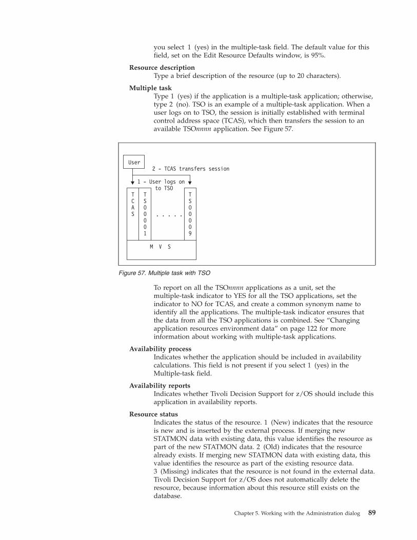
you select 1 (yes) in the multiple-task field. The default value for this
field, set on the Edit Resource Defaults window, is 95%.
Resource description
Type a brief description of the resource (up to 20 characters).
Multiple task
Type 1 (yes) if the application is a multiple-task application; otherwise,
type 2 (no). TSO is an example of a multiple-task application. When a
user logs on to TSO, the session is initially established with terminal
control address space (TCAS), which then transfers the session to an
available TSOnnnn application. See Figure 57.
To report on all the TSOnnnn applications as a unit, set the
multiple-task indicator to YES for all the TSO applications, set the
indicator to NO for TCAS, and create a common synonym name to
identify all the applications. The multiple-task indicator ensures that
the data from all the TSO applications is combined. See “Changing
application resources environment data” on page 122 for more
information about working with multiple-task applications.
Availability process
Indicates whether the application should be included in availability
calculations. This field is not present if you select 1 (yes) in the
Multiple-task field.
Availability reports
Indicates whether Tivoli Decision Support for z/OS should include this
application in availability reports.
Resource status
Indicates the status of the resource. 1 (New) indicates that the resource
is new and is inserted by the external process. If merging new
STATMON data with existing data, this value identifies the resource as
part of the new STATMON data. 2 (Old) indicates that the resource
already exists. If merging new STATMON data with existing data, this
value identifies the resource as part of the existing resource data.
3 (Missing) indicates that the resource is not found in the external data.
Tivoli Decision Support for z/OS does not automatically delete the
resource, because information about this resource still exists on the
database.
User
TCAS
TSO0001
1 - User logs onto TSO
2 - TCAS transfers session
TSO0009
M V S
. . . . .
Figure 57. Multiple task with TSO
Chapter 5. Working with the Administration dialog 89
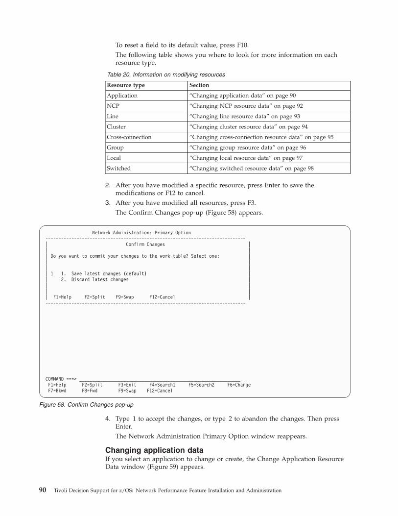
To reset a field to its default value, press F10.
The following table shows you where to look for more information on each
resource type.
Table 20. Information on modifying resources
Resource type Section
Application “Changing application data” on page 90
NCP “Changing NCP resource data” on page 92
Line “Changing line resource data” on page 93
Cluster “Changing cluster resource data” on page 94
Cross-connection “Changing cross-connection resource data” on page 95
Group “Changing group resource data” on page 96
Local “Changing local resource data” on page 97
Switched “Changing switched resource data” on page 98
2. After you have modified a specific resource, press Enter to save the
modifications or F12 to cancel.
3. After you have modified all resources, press F3.
The Confirm Changes pop-up (Figure 58) appears.
4. Type 1 to accept the changes, or type 2 to abandon the changes. Then press
Enter.
The Network Administration Primary Option window reappears.
Changing application data
If you select an application to change or create, the Change Application Resource
Data window (Figure 59) appears.
Network Administration: Primary Option
-----------------------------------------------------------------------------
| Confirm Changes |
| |
| Do you want to commit your changes to the work table? Select one: |
| |
| |
| 1 1. Save latest changes (default) |
| 2. Discard latest changes |
| |
| |
| F1=Help F2=Split F9=Swap F12=Cancel |
-----------------------------------------------------------------------------
COMMAND ===> ______________________________________________________________
F1=Help F2=Split F3=Exit F4=Search1 F5=Search2 F6=Change
F7=Bkwd F8=Fwd F9=Swap F12=Cancel
Figure 58. Confirm Changes pop-up
90 Tivoli Decision Support for z/OS: Network Performance Feature Installation and Administration
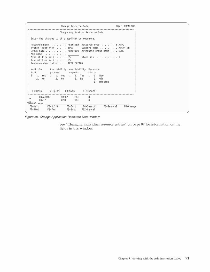
See “Changing individual resource entries” on page 87 for information on the
fields in this window.
Change Resource Data ROW 1 FROM 686
-----------------------------------------------------------------------------
| Change Application Resource Data |
| |
| Enter the changes to this application resource. |
| |
| Resource name . . . . . . AB6K4TEH Resource type . . . . . : APPL |
| System identifier . . . . IPO1 Synonym name . . . . . . . AB6K4TEH |
| Group name . . . . . . . . ABZ6V10U Alternate group name . . . NONE |
| ACB name . . . . . . . . . ________ |
| Availability in % . . . . 95 Stability . . . . . . . . 1 |
| Transit time in % . . . . 95 |
| Resource description . . . APPLICATION |
| |
| Multiple Availability Availability Resource |
| task process reports status |
| 2 1. Yes 1 1. Yes 1 1. Yes 1 1. New |
| 2. No 2. No 2. No 2. Old |
| 3. Missing |
| |
| |
| F1=Help F2=Split F9=Swap F12=Cancel |
-----------------------------------------------------------------------------
_ CNMATPNS GROUP IPO1 O
_ CNMIC APPL IPO1 O
COMMAND ===> ______________________________________________________________
F1=Help F2=Split F3=Exit F4=Search1 F5=Search2 F6=Change
F7=Bkwd F8=Fwd F9=Swap F12=Cancel
Figure 59. Change Application Resource Data window
Chapter 5. Working with the Administration dialog 91
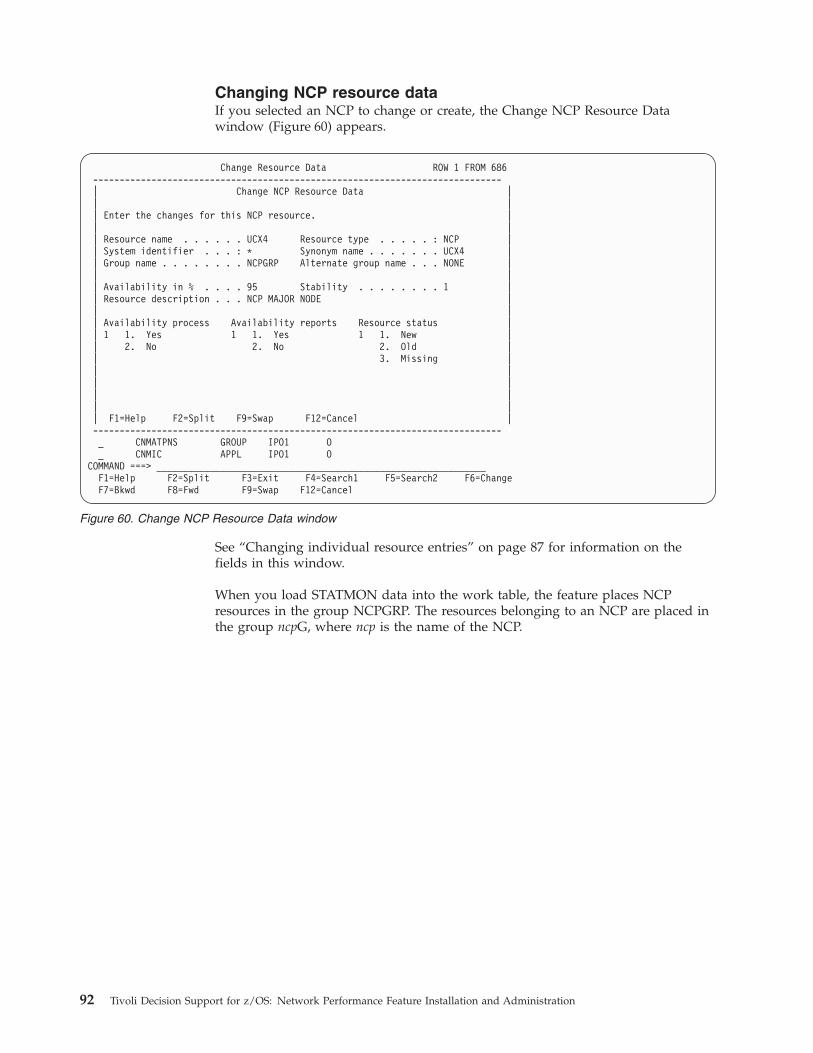
Changing NCP resource data
If you selected an NCP to change or create, the Change NCP Resource Data
window (Figure 60) appears.
See “Changing individual resource entries” on page 87 for information on the
fields in this window.
When you load STATMON data into the work table, the feature places NCP
resources in the group NCPGRP. The resources belonging to an NCP are placed in
the group ncpG, where ncp is the name of the NCP.
Change Resource Data ROW 1 FROM 686
-----------------------------------------------------------------------------
| Change NCP Resource Data |
| |
| Enter the changes for this NCP resource. |
| |
| Resource name . . . . . . UCX4 Resource type . . . . . : NCP |
| System identifier . . . : * Synonym name . . . . . . . UCX4 |
| Group name . . . . . . . . NCPGRP Alternate group name . . . NONE |
| |
| Availability in % . . . . 95 Stability . . . . . . . . 1 |
| Resource description . . . NCP MAJOR NODE |
| |
| Availability process Availability reports Resource status |
| 1 1. Yes 1 1. Yes 1 1. New |
| 2. No 2. No 2. Old |
| 3. Missing |
| |
| |
| |
| |
| F1=Help F2=Split F9=Swap F12=Cancel |
-----------------------------------------------------------------------------
_ CNMATPNS GROUP IPO1 O
_ CNMIC APPL IPO1 O
COMMAND ===> ______________________________________________________________
F1=Help F2=Split F3=Exit F4=Search1 F5=Search2 F6=Change
F7=Bkwd F8=Fwd F9=Swap F12=Cancel
Figure 60. Change NCP Resource Data window
92 Tivoli Decision Support for z/OS: Network Performance Feature Installation and Administration
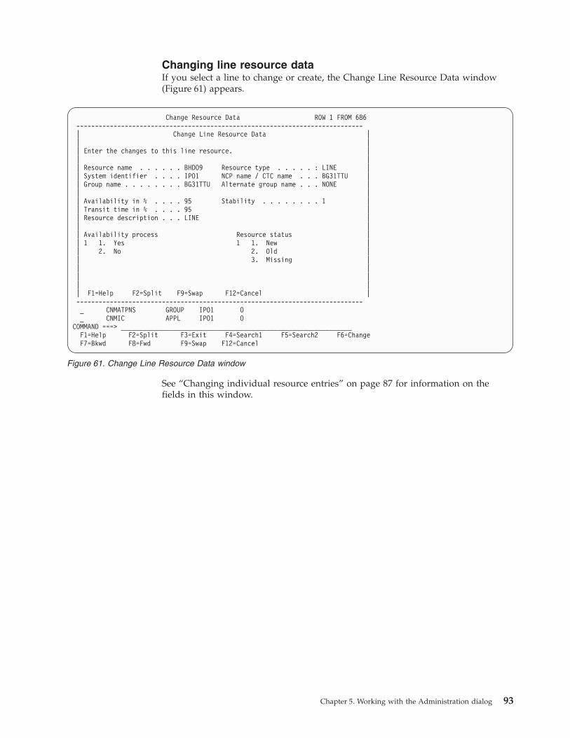
Changing line resource data
If you select a line to change or create, the Change Line Resource Data window
(Figure 61) appears.
See “Changing individual resource entries” on page 87 for information on the
fields in this window.
Change Resource Data ROW 1 FROM 686
-----------------------------------------------------------------------------
| Change Line Resource Data |
| |
| Enter the changes to this line resource. |
| |
| Resource name . . . . . . BHDO9 Resource type . . . . . : LINE |
| System identifier . . . . IPO1 NCP name / CTC name . . . BG31TTU |
| Group name . . . . . . . . BG31TTU Alternate group name . . . NONE |
| |
| Availability in % . . . . 95 Stability . . . . . . . . 1 |
| Transit time in % . . . . 95 |
| Resource description . . . LINE |
| |
| Availability process Resource status |
| 1 1. Yes 1 1. New |
| 2. No 2. Old |
| 3. Missing |
| |
| |
| |
| F1=Help F2=Split F9=Swap F12=Cancel |
-----------------------------------------------------------------------------
_ CNMATPNS GROUP IPO1 O
_ CNMIC APPL IPO1 O
COMMAND ===> ______________________________________________________________
F1=Help F2=Split F3=Exit F4=Search1 F5=Search2 F6=Change
F7=Bkwd F8=Fwd F9=Swap F12=Cancel
Figure 61. Change Line Resource Data window
Chapter 5. Working with the Administration dialog 93
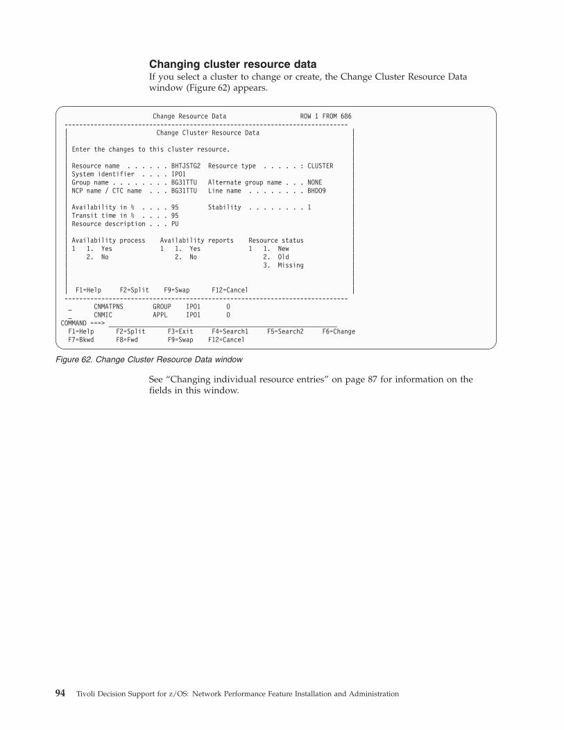
Changing cluster resource data
If you select a cluster to change or create, the Change Cluster Resource Data
window (Figure 62) appears.
See “Changing individual resource entries” on page 87 for information on the
fields in this window.
Change Resource Data ROW 1 FROM 686
-----------------------------------------------------------------------------
| Change Cluster Resource Data |
| |
| Enter the changes to this cluster resource. |
| |
| Resource name . . . . . . BHTJSTG2 Resource type . . . . . : CLUSTER |
| System identifier . . . . IPO1 |
| Group name . . . . . . . . BG31TTU Alternate group name . . . NONE |
| NCP name / CTC name . . . BG31TTU Line name . . . . . . . . BHDO9 |
| |
| Availability in % . . . . 95 Stability . . . . . . . . 1 |
| Transit time in % . . . . 95 |
| Resource description . . . PU |
| |
| Availability process Availability reports Resource status |
| 1 1. Yes 1 1. Yes 1 1. New |
| 2. No 2. No 2. Old |
| 3. Missing |
| |
| |
| F1=Help F2=Split F9=Swap F12=Cancel |
-----------------------------------------------------------------------------
_ CNMATPNS GROUP IPO1 O
_ CNMIC APPL IPO1 O
COMMAND ===> ______________________________________________________________
F1=Help F2=Split F3=Exit F4=Search1 F5=Search2 F6=Change
F7=Bkwd F8=Fwd F9=Swap F12=Cancel
Figure 62. Change Cluster Resource Data window
94 Tivoli Decision Support for z/OS: Network Performance Feature Installation and Administration
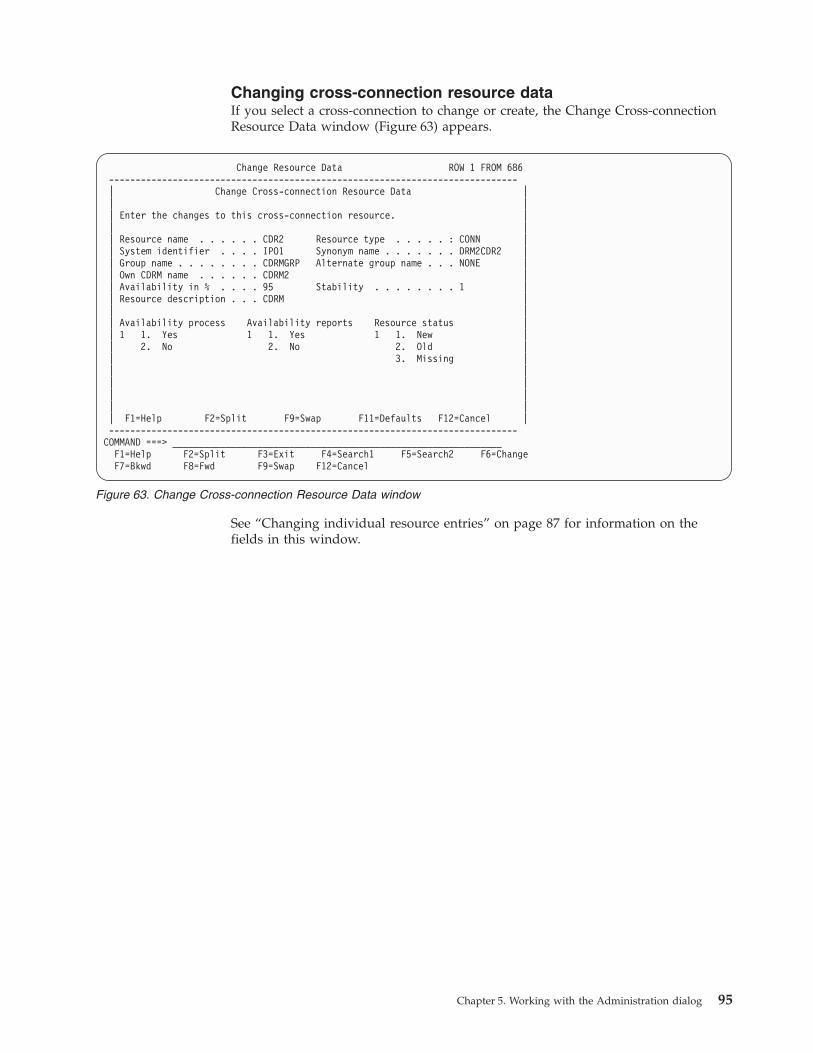
Changing cross-connection resource data
If you select a cross-connection to change or create, the Change Cross-connection
Resource Data window (Figure 63) appears.
See “Changing individual resource entries” on page 87 for information on the
fields in this window.
Change Resource Data ROW 1 FROM 686
-----------------------------------------------------------------------------
| Change Cross-connection Resource Data |
| |
| Enter the changes to this cross-connection resource. |
| |
| Resource name . . . . . . CDR2 Resource type . . . . . : CONN |
| System identifier . . . . IPO1 Synonym name . . . . . . . DRM2CDR2 |
| Group name . . . . . . . . CDRMGRP Alternate group name . . . NONE |
| Own CDRM name . . . . . . CDRM2 |
| Availability in % . . . . 95 Stability . . . . . . . . 1 |
| Resource description . . . CDRM |
| |
| Availability process Availability reports Resource status |
| 1 1. Yes 1 1. Yes 1 1. New |
| 2. No 2. No 2. Old |
| 3. Missing |
| |
| |
| |
| |
| F1=Help F2=Split F9=Swap F11=Defaults F12=Cancel |
-----------------------------------------------------------------------------
COMMAND ===> ______________________________________________________________
F1=Help F2=Split F3=Exit F4=Search1 F5=Search2 F6=Change
F7=Bkwd F8=Fwd F9=Swap F12=Cancel
Figure 63. Change Cross-connection Resource Data window
Chapter 5. Working with the Administration dialog 95
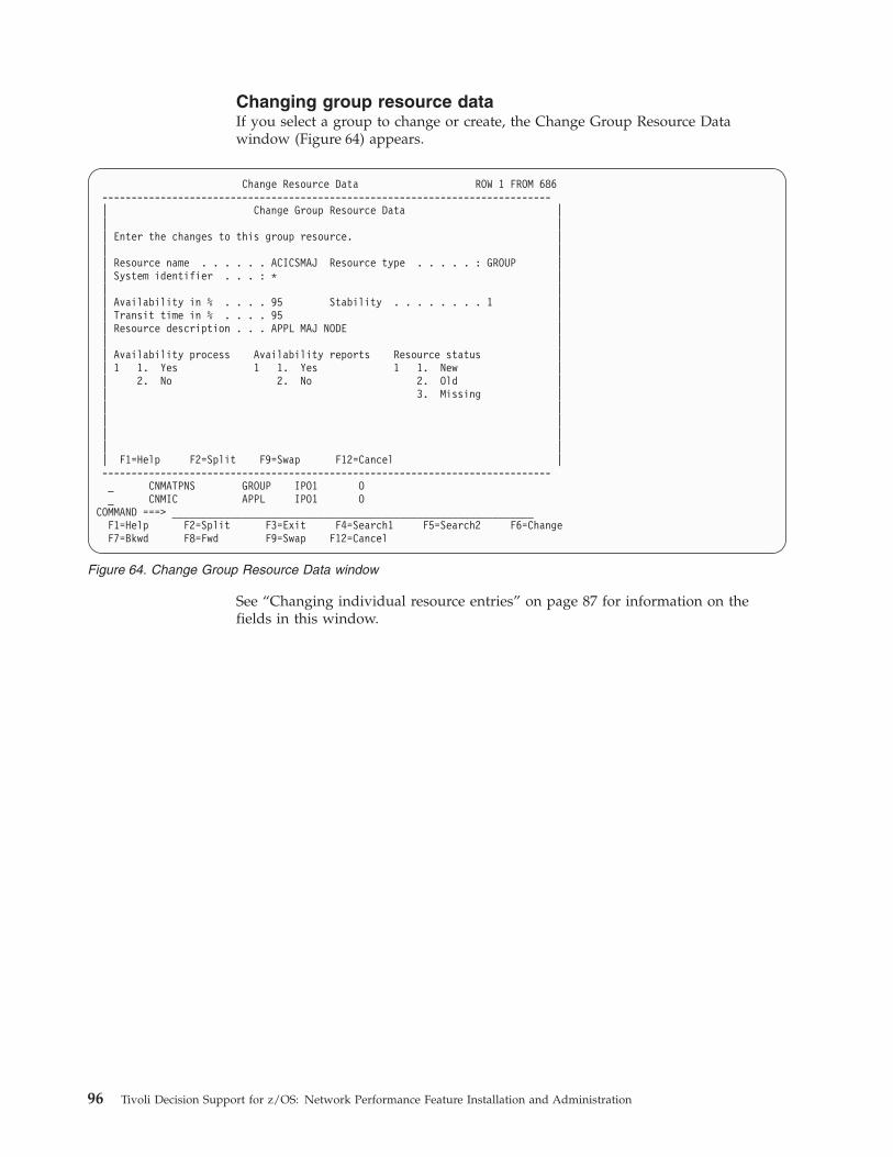
Changing group resource data
If you select a group to change or create, the Change Group Resource Data
window (Figure 64) appears.
See “Changing individual resource entries” on page 87 for information on the
fields in this window.
Change Resource Data ROW 1 FROM 686
-----------------------------------------------------------------------------
| Change Group Resource Data |
| |
| Enter the changes to this group resource. |
| |
| Resource name . . . . . . ACICSMAJ Resource type . . . . . : GROUP |
| System identifier . . . : * |
| |
| Availability in % . . . . 95 Stability . . . . . . . . 1 |
| Transit time in % . . . . 95 |
| Resource description . . . APPL MAJ NODE |
| |
| Availability process Availability reports Resource status |
| 1 1. Yes 1 1. Yes 1 1. New |
| 2. No 2. No 2. Old |
| 3. Missing |
| |
| |
| |
| |
| F1=Help F2=Split F9=Swap F12=Cancel |
-----------------------------------------------------------------------------
_ CNMATPNS GROUP IPO1 O
_ CNMIC APPL IPO1 O
COMMAND ===> ______________________________________________________________
F1=Help F2=Split F3=Exit F4=Search1 F5=Search2 F6=Change
F7=Bkwd F8=Fwd F9=Swap F12=Cancel
Figure 64. Change Group Resource Data window
96 Tivoli Decision Support for z/OS: Network Performance Feature Installation and Administration
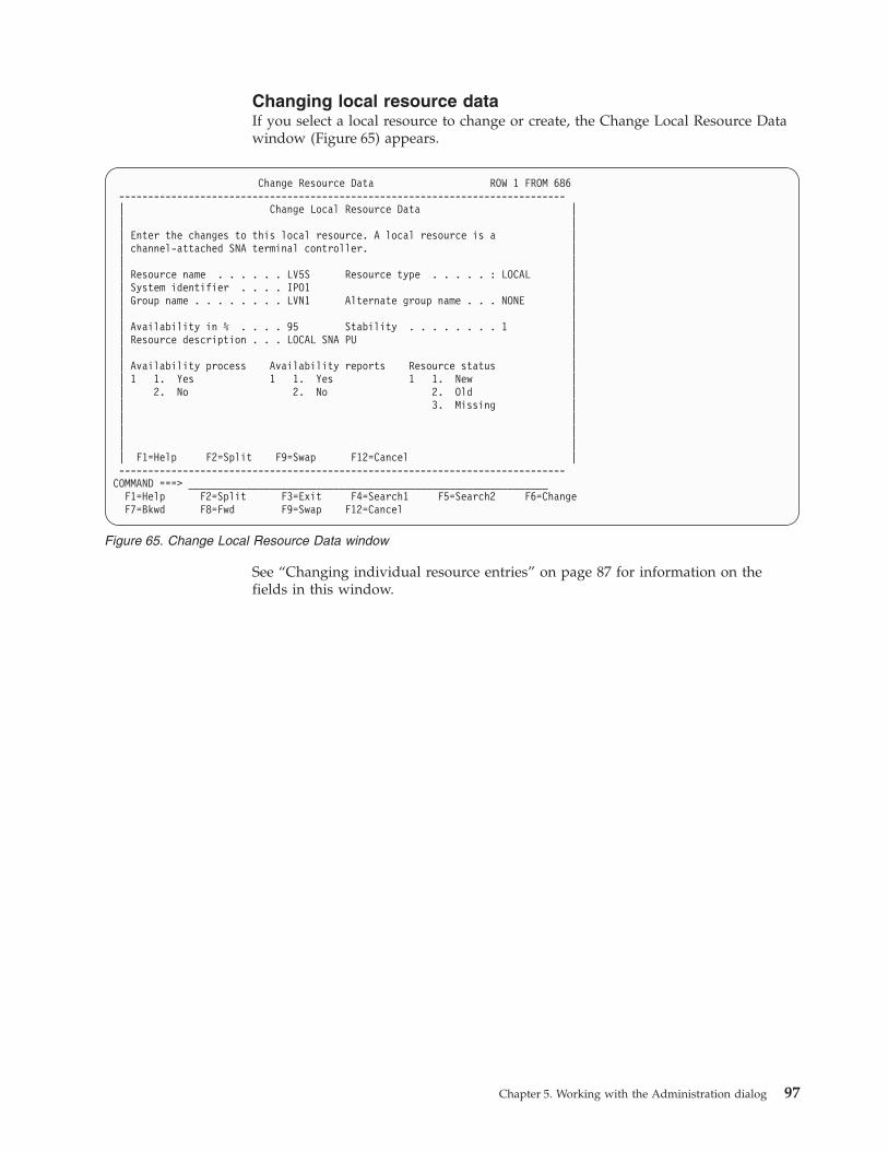
Changing local resource data
If you select a local resource to change or create, the Change Local Resource Data
window (Figure 65) appears.
See “Changing individual resource entries” on page 87 for information on the
fields in this window.
Change Resource Data ROW 1 FROM 686
-----------------------------------------------------------------------------
| Change Local Resource Data |
| |
| Enter the changes to this local resource. A local resource is a |
| channel-attached SNA terminal controller. |
| |
| Resource name . . . . . . LV5S Resource type . . . . . : LOCAL |
| System identifier . . . . IPO1 |
| Group name . . . . . . . . LVN1 Alternate group name . . . NONE |
| |
| Availability in % . . . . 95 Stability . . . . . . . . 1 |
| Resource description . . . LOCAL SNA PU |
| |
| Availability process Availability reports Resource status |
| 1 1. Yes 1 1. Yes 1 1. New |
| 2. No 2. No 2. Old |
| 3. Missing |
| |
| |
| |
| F1=Help F2=Split F9=Swap F12=Cancel |
-----------------------------------------------------------------------------
COMMAND ===> ______________________________________________________________
F1=Help F2=Split F3=Exit F4=Search1 F5=Search2 F6=Change
F7=Bkwd F8=Fwd F9=Swap F12=Cancel
Figure 65. Change Local Resource Data window
Chapter 5. Working with the Administration dialog 97
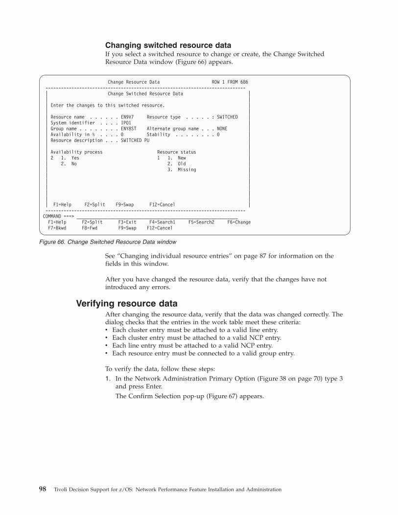
Changing switched resource data
If you select a switched resource to change or create, the Change Switched
Resource Data window (Figure 66) appears.
See “Changing individual resource entries” on page 87 for information on the
fields in this window.
After you have changed the resource data, verify that the changes have not
introduced any errors.
Verifying resource data
After changing the resource data, verify that the data was changed correctly. The
dialog checks that the entries in the work table meet these criteria:
v Each cluster entry must be attached to a valid line entry.
v Each cluster entry must be attached to a valid NCP entry.
v Each line entry must be attached to a valid NCP entry.
v Each resource entry must be connected to a valid group entry.
To verify the data, follow these steps:
1. In the Network Administration Primary Option (Figure 38 on page 70) type 3
and press Enter.
The Confirm Selection pop-up (Figure 67) appears.
Change Resource Data ROW 1 FROM 686
-----------------------------------------------------------------------------
| Change Switched Resource Data |
| |
| Enter the changes to this switched resource. |
| |
| Resource name . . . . . . EN9V7 Resource type . . . . . : SWITCHED |
| System identifier . . . . IPO1 |
| Group name . . . . . . . . ENY8ST Alternate group name . . . NONE |
| Availability in % . . . . 0 Stability . . . . . . . . 0 |
| Resource description . . . SWITCHED PU |
| |
| Availability process Resource status |
| 2 1. Yes 1 1. New |
| 2. No 2. Old |
| 3. Missing |
| |
| |
| |
| |
| |
| F1=Help F2=Split F9=Swap F12=Cancel |
-----------------------------------------------------------------------------
COMMAND ===> ______________________________________________________________
F1=Help F2=Split F3=Exit F4=Search1 F5=Search2 F6=Change
F7=Bkwd F8=Fwd F9=Swap F12=Cancel
Figure 66. Change Switched Resource Data window
98 Tivoli Decision Support for z/OS: Network Performance Feature Installation and Administration
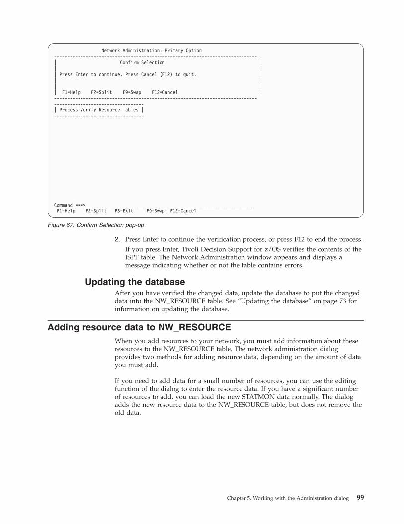
2. Press Enter to continue the verification process, or press F12 to end the process.
If you press Enter, Tivoli Decision Support for z/OS verifies the contents of the
ISPF table. The Network Administration window appears and displays a
message indicating whether or not the table contains errors.
Updating the database
After you have verified the changed data, update the database to put the changed
data into the NW_RESOURCE table. See “Updating the database” on page 73 for
information on updating the database.
Adding resource data to NW_RESOURCE
When you add resources to your network, you must add information about these
resources to the NW_RESOURCE table. The network administration dialog
provides two methods for adding resource data, depending on the amount of data
you must add.
If you need to add data for a small number of resources, you can use the editing
function of the dialog to enter the resource data. If you have a significant number
of resources to add, you can load the new STATMON data normally. The dialog
adds the new resource data to the NW_RESOURCE table, but does not remove the
old data.
Network Administration: Primary Option
-----------------------------------------------------------------------------
| Confirm Selection |
| |
| Press Enter to continue. Press Cancel (F12) to quit. |
| |
| |
| F1=Help F2=Split F9=Swap F12=Cancel |
-----------------------------------------------------------------------------
----------------------------------
| Process Verify Resource Tables |
----------------------------------
Command ===> ______________________________________________________________
F1=Help F2=Split F3=Exit F9=Swap F12=Cancel
Figure 67. Confirm Selection pop-up
Chapter 5. Working with the Administration dialog 99
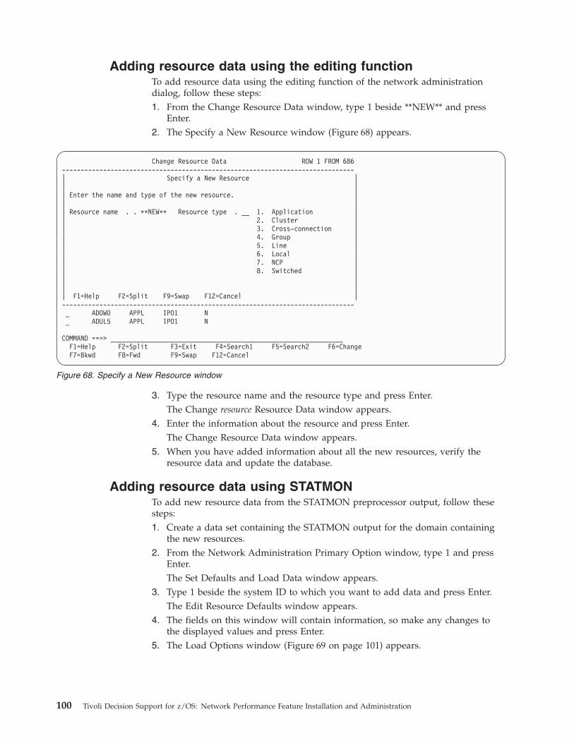
Adding resource data using the editing function
To add resource data using the editing function of the network administration
dialog, follow these steps:
1. From the Change Resource Data window, type 1 beside **NEW** and press
Enter.
2. The Specify a New Resource window (Figure 68) appears.
3. Type the resource name and the resource type and press Enter.
The Change resource Resource Data window appears.
4. Enter the information about the resource and press Enter.
The Change Resource Data window appears.
5. When you have added information about all the new resources, verify the
resource data and update the database.
Adding resource data using STATMON
To add new resource data from the STATMON preprocessor output, follow these
steps:
1. Create a data set containing the STATMON output for the domain containing
the new resources.
2. From the Network Administration Primary Option window, type 1 and press
Enter.
The Set Defaults and Load Data window appears.
3. Type 1 beside the system ID to which you want to add data and press Enter.
The Edit Resource Defaults window appears.
4. The fields on this window will contain information, so make any changes to
the displayed values and press Enter.
5. The Load Options window (Figure 69 on page 101) appears.
Change Resource Data ROW 1 FROM 686
------------------------------------------------------------------------------
| Specify a New Resource |
| |
| Enter the name and type of the new resource. |
| |
| Resource name . . **NEW** Resource type . __ 1. Application |
| 2. Cluster |
| 3. Cross-connection |
| 4. Group |
| 5. Line |
| 6. Local |
| 7. NCP |
| 8. Switched |
| |
| |
| F1=Help F2=Split F9=Swap F12=Cancel |
------------------------------------------------------------------------------
_ ADOWO APPL IPO1 N
_ ADUL5 APPL IPO1 N
COMMAND ===> ______________________________________________________________
F1=Help F2=Split F3=Exit F4=Search1 F5=Search2 F6=Change
F7=Bkwd F8=Fwd F9=Swap F12=Cancel
Figure 68. Specify a New Resource window
100 Tivoli Decision Support for z/OS: Network Performance Feature Installation and Administration
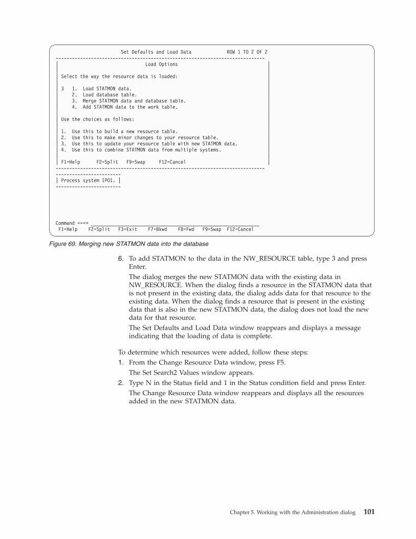
6. To add STATMON to the data in the NW_RESOURCE table, type 3 and press
Enter.
The dialog merges the new STATMON data with the existing data in
NW_RESOURCE. When the dialog finds a resource in the STATMON data that
is not present in the existing data, the dialog adds data for that resource to the
existing data. When the dialog finds a resource that is present in the existing
data that is also in the new STATMON data, the dialog does not load the new
data for that resource.
The Set Defaults and Load Data window reappears and displays a message
indicating that the loading of data is complete.
To determine which resources were added, follow these steps:
1. From the Change Resource Data window, press F5.
The Set Search2 Values window appears.
2. Type N in the Status field and 1 in the Status condition field and press Enter.
The Change Resource Data window reappears and displays all the resources
added in the new STATMON data.
Set Defaults and Load Data ROW 1 TO 2 OF 2
-----------------------------------------------------------------------------
| Load Options |
| |
| Select the way the resource data is loaded: |
| |
| 3 1. Load STATMON data. |
| 2. Load database table. |
| 3. Merge STATMON data and database table. |
| 4. Add STATMON data to the work table. |
| |
| Use the choices as follows: |
| |
| 1. Use this to build a new resource table. |
| 2. Use this to make minor changes to your resource table. |
| 3. Use this to update your resource table with new STATMON data. |
| 4. Use this to combine STATMON data from multiple systems. |
| |
| F1=Help F2=Split F9=Swap F12=Cancel |
-----------------------------------------------------------------------------
------------------------
| Process system IPO1. |
------------------------
Command ===> ______________________________________________________________
F1=Help F2=Split F3=Exit F7=Bkwd F8=Fwd F9=Swap F12=Cancel
Figure 69. Merging new STATMON data into the database
Chapter 5. Working with the Administration dialog 101
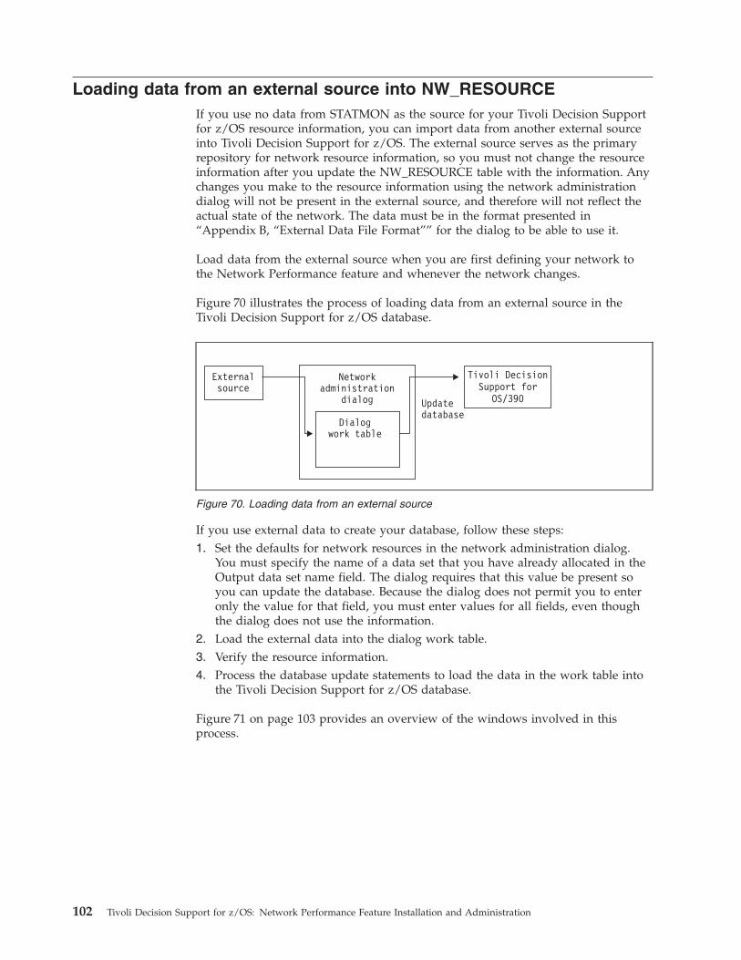
Loading data from an external source into NW_RESOURCE
If you use no data from STATMON as the source for your Tivoli Decision Support
for z/OS resource information, you can import data from another external source
into Tivoli Decision Support for z/OS. The external source serves as the primary
repository for network resource information, so you must not change the resource
information after you update the NW_RESOURCE table with the information. Any
changes you make to the resource information using the network administration
dialog will not be present in the external source, and therefore will not reflect the
actual state of the network. The data must be in the format presented in
“Appendix B, “External Data File Format”” for the dialog to be able to use it.
Load data from the external source when you are first defining your network to
the Network Performance feature and whenever the network changes.
Figure 70 illustrates the process of loading data from an external source in the
Tivoli Decision Support for z/OS database.
If you use external data to create your database, follow these steps:
1. Set the defaults for network resources in the network administration dialog.
You must specify the name of a data set that you have already allocated in the
Output data set name field. The dialog requires that this value be present so
you can update the database. Because the dialog does not permit you to enter
only the value for that field, you must enter values for all fields, even though
the dialog does not use the information.
2. Load the external data into the dialog work table.
3. Verify the resource information.
4. Process the database update statements to load the data in the work table into
the Tivoli Decision Support for z/OS database.
Figure 71 on page 103 provides an overview of the windows involved in this
process.
Figure 70. Loading data from an external source
102 Tivoli Decision Support for z/OS: Network Performance Feature Installation and Administration
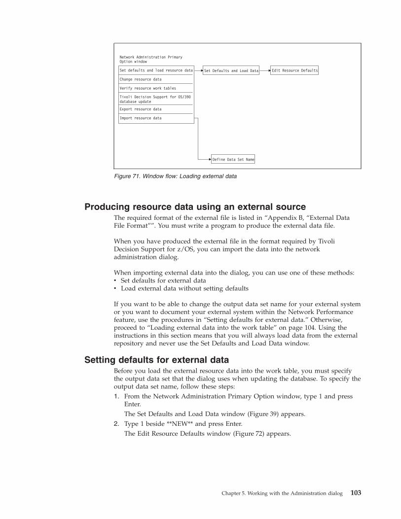
Producing resource data using an external source
The required format of the external file is listed in “Appendix B, “External Data
File Format””. You must write a program to produce the external data file.
When you have produced the external file in the format required by Tivoli
Decision Support for z/OS, you can import the data into the network
administration dialog.
When importing external data into the dialog, you can use one of these methods:
v Set defaults for external data
v Load external data without setting defaults
If you want to be able to change the output data set name for your external system
or you want to document your external system within the Network Performance
feature, use the procedures in “Setting defaults for external data.” Otherwise,
proceed to “Loading external data into the work table” on page 104. Using the
instructions in this section means that you will always load data from the external
repository and never use the Set Defaults and Load Data window.
Setting defaults for external data
Before you load the external resource data into the work table, you must specify
the output data set that the dialog uses when updating the database. To specify the
output data set name, follow these steps:
1. From the Network Administration Primary Option window, type 1 and press
Enter.
The Set Defaults and Load Data window (Figure 39) appears.
2. Type 1 beside **NEW** and press Enter.
The Edit Resource Defaults window (Figure 72) appears.
Figure 71. Window flow: Loading external data
Chapter 5. Working with the Administration dialog 103
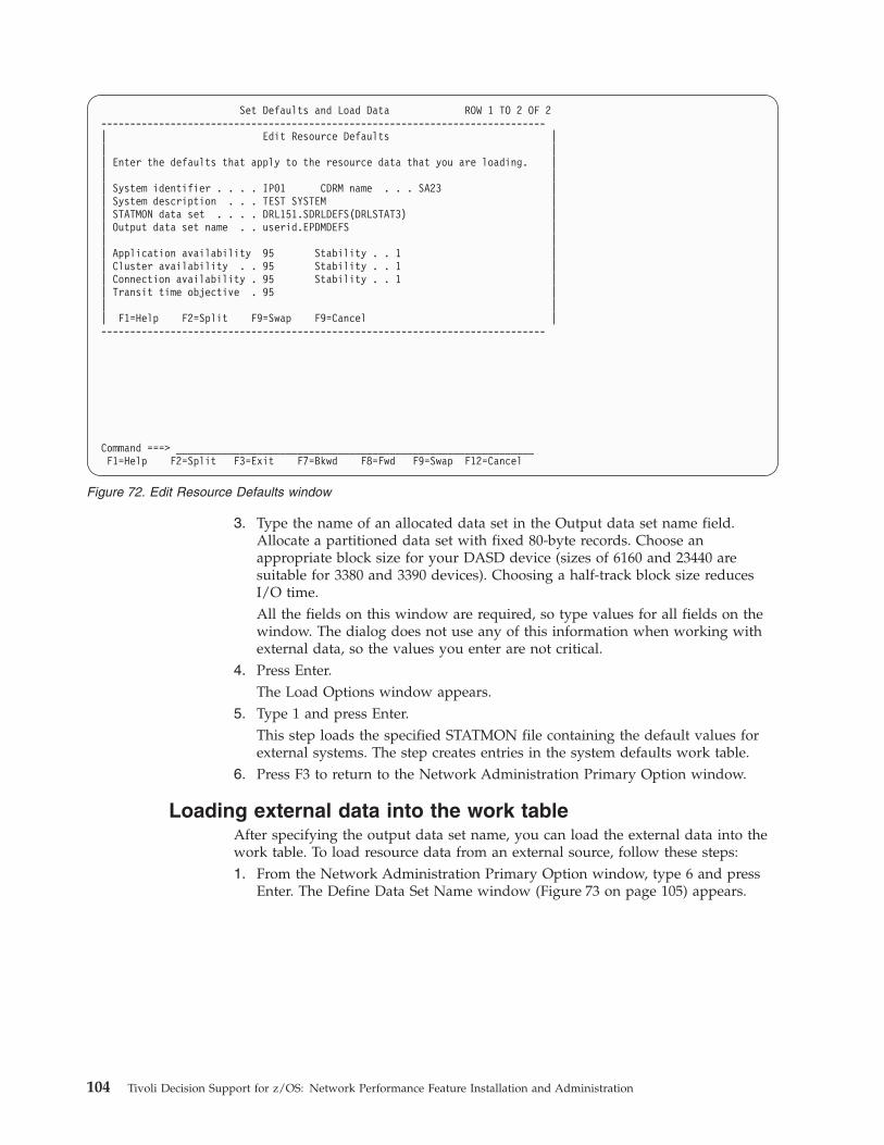
3. Type the name of an allocated data set in the Output data set name field.
Allocate a partitioned data set with fixed 80-byte records. Choose an
appropriate block size for your DASD device (sizes of 6160 and 23440 are
suitable for 3380 and 3390 devices). Choosing a half-track block size reduces
I/O time.
All the fields on this window are required, so type values for all fields on the
window. The dialog does not use any of this information when working with
external data, so the values you enter are not critical.
4. Press Enter.
The Load Options window appears.
5. Type 1 and press Enter.
This step loads the specified STATMON file containing the default values for
external systems. The step creates entries in the system defaults work table.
6. Press F3 to return to the Network Administration Primary Option window.
Loading external data into the work table
After specifying the output data set name, you can load the external data into the
work table. To load resource data from an external source, follow these steps:
1. From the Network Administration Primary Option window, type 6 and press
Enter. The Define Data Set Name window (Figure 73 on page 105) appears.
Set Defaults and Load Data ROW 1 TO 2 OF 2
-----------------------------------------------------------------------------
| Edit Resource Defaults |
| |
| Enter the defaults that apply to the resource data that you are loading. |
| |
| System identifier . . . . IP01 CDRM name . . . SA23 |
| System description . . . TEST SYSTEM |
| STATMON data set . . . . DRL151.SDRLDEFS(DRLSTAT3) |
| Output data set name . . userid.EPDMDEFS |
| |
| Application availability 95 Stability . . 1 |
| Cluster availability . . 95 Stability . . 1 |
| Connection availability . 95 Stability . . 1 |
| Transit time objective . 95 |
| |
| F1=Help F2=Split F9=Swap F9=Cancel |
-----------------------------------------------------------------------------
Command ===> ______________________________________________________________
F1=Help F2=Split F3=Exit F7=Bkwd F8=Fwd F9=Swap F12=Cancel
Figure 72. Edit Resource Defaults window
104 Tivoli Decision Support for z/OS: Network Performance Feature Installation and Administration
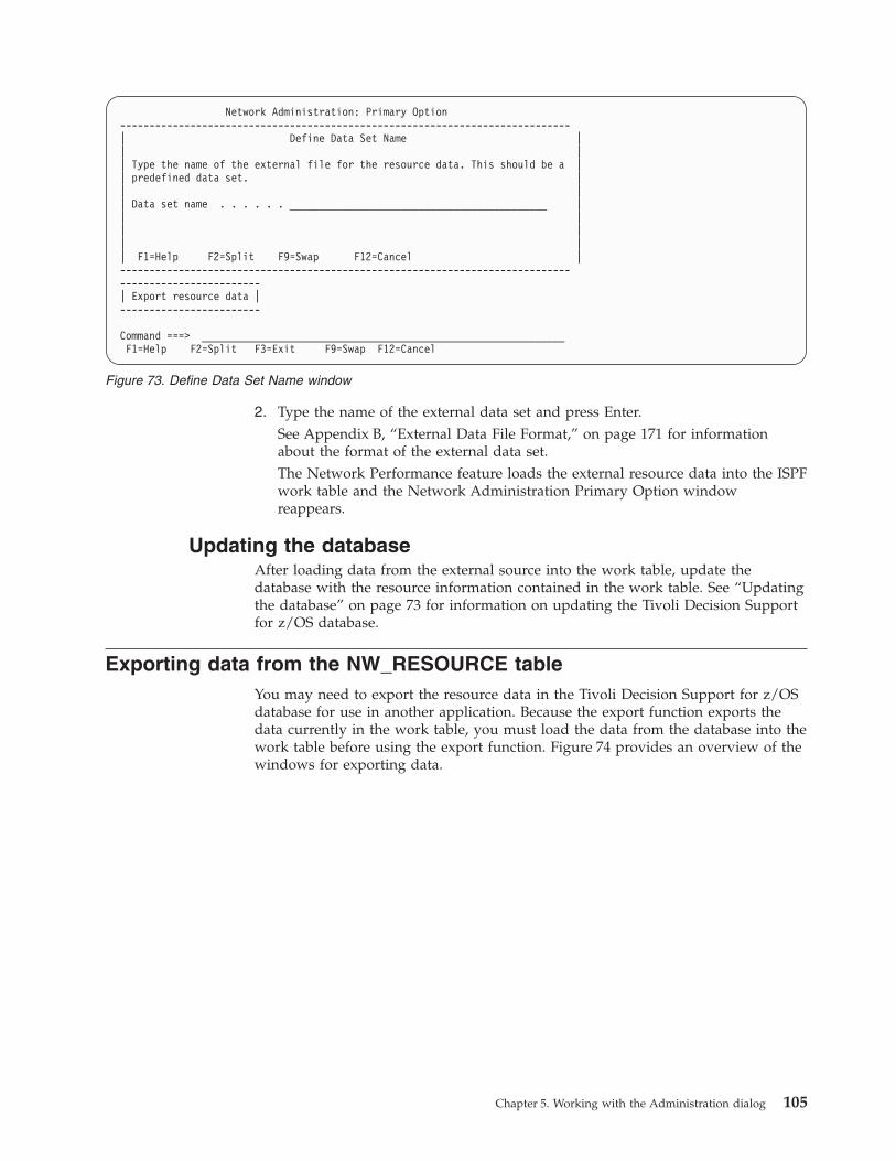
2. Type the name of the external data set and press Enter.
See Appendix B, “External Data File Format,” on page 171 for information
about the format of the external data set.
The Network Performance feature loads the external resource data into the ISPF
work table and the Network Administration Primary Option window
reappears.
Updating the database
After loading data from the external source into the work table, update the
database with the resource information contained in the work table. See “Updating
the database” on page 73 for information on updating the Tivoli Decision Support
for z/OS database.
Exporting data from the NW_RESOURCE table
You may need to export the resource data in the Tivoli Decision Support for z/OS
database for use in another application. Because the export function exports the
data currently in the work table, you must load the data from the database into the
work table before using the export function. Figure 74 provides an overview of the
windows for exporting data.
Network Administration: Primary Option
-----------------------------------------------------------------------------
| Define Data Set Name |
| |
| Type the name of the external file for the resource data. This should be a |
| predefined data set. |
| |
| Data set name . . . . . . ____________________________________________ |
| |
| |
| |
| F1=Help F2=Split F9=Swap F12=Cancel |
-----------------------------------------------------------------------------
------------------------
| Export resource data |
------------------------
Command ===> ______________________________________________________________
F1=Help F2=Split F3=Exit F9=Swap F12=Cancel
Figure 73. Define Data Set Name window
Chapter 5. Working with the Administration dialog 105
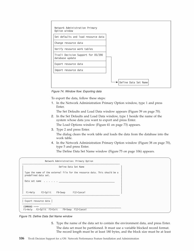
To export the data, follow these steps:
1. In the Network Administration Primary Option window, type 1 and press
Enter.
The Set Defaults and Load Data window appears (Figure 39 on page 70).
2. In the Set Defaults and Load Data window, type 1 beside the name of the
system whose data you want to export and press Enter.
The Load Options window (Figure 41 on page 73) appears.
3. Type 2 and press Enter.
The dialog clears the work table and loads the data from the database into the
work table.
4. In the Network Administration Primary Option window (Figure 38 on page 70),
type 5 and press Enter.
The Define Data Set Name window (Figure 75 on page 106) appears.
5. Type the name of the data set to contain the environment data, and press Enter.
The data set must be partitioned. It must use a variable blocked record format.
The record length must be at least 180 bytes, and the block size must be at least
Figure 74. Window flow: Exporting data
Network Administration: Primary Option
-----------------------------------------------------------------------------
| Define Data Set Name |
| |
| Type the name of the external file for the resource data. This should be a |
| predefined data set. |
| |
| Data set name . . . . . . ____________________________________________ |
| |
| |
| |
| F1=Help F2=Split F9=Swap F12=Cancel |
-----------------------------------------------------------------------------
-----------------------
| Export resource data |
-----------------------
COMMAND ===> ________________________________________________________________
F1=Help F2=Split F3=Exit F9=Swap F12=Cancel
Figure 75. Define Data Set Name window
106 Tivoli Decision Support for z/OS: Network Performance Feature Installation and Administration
184 bytes. Tivoli Decision Support for z/OS automatically generates a member
in this data set with the name Ejjjhhmm, where:
E Indicates that the member contains exported data
jjj Specifies the Julian date when the data was exported
hh Specifies the hour when the data was exported
mm Specifies the minute when the data was exportedTivoli Decision Support for z/OS exports the data and the Network
Administration Primary Option window reappears.
The data in the external file uses the format described in Appendix B, “External
Data File Format,” on page 171.
Chapter 5. Working with the Administration dialog 107

108 Tivoli Decision Support for z/OS: Network Performance Feature Installation and Administration
Chapter 6. Administration Dialog Example
This chapter provides an example of the steps involved in defining network
resource information using the network administration dialog. The example uses
the sample network data supplied with the installation tape to completely define
the network, starting with STATMON output.
Chapter 5, “Working with the Network Performance feature Administration
dialog,” on page 61 describes the procedures used in this chapter. Appendix A,
“Sample STATMON Inputs and Outputs,” on page 167 lists an extract of the
sample data used in the example.
Understanding the sample network
The sample network contains commonly found resources and uses a common
configuration. The network consists of two domains, linked by a
channel-to-channel connection and consisting of these resources:
v One NCP, running in a 3725 controller
v One TSO application in the domain 1 host system, with each application
containing five applications for TSO users
v Lines, clusters, and terminals in each host system
v One IMS application in domain 1
v Local SNA PUs
Figure 76 on page 110 illustrates the network configuration.
109
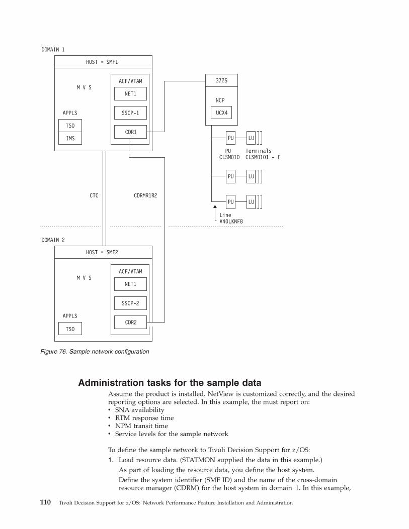
Administration tasks for the sample data
Assume the product is installed. NetView is customized correctly, and the desired
reporting options are selected. In this example, the must report on:
v SNA availability
v RTM response time
v NPM transit time
v Service levels for the sample network
To define the sample network to Tivoli Decision Support for z/OS:
1. Load resource data. (STATMON supplied the data in this example.)
As part of loading the resource data, you define the host system.
Define the system identifier (SMF ID) and the name of the cross-domain
resource manager (CDRM) for the host system in domain 1. In this example,
HOST = SMF1
3725
NCP
UCX4
PU
PU
PU
PUCLSM010
TerminalsCLSM0101 - F
LineV40LKNF8
LU
LU
LU
HOST = SMF2
DOMAIN 1
DOMAIN 2
M V S
M V S
ACF/VTAM
ACF/VTAM
NET1
NET1
SSCP-1
SSCP-2
CDR1
CDR2
CDRMR1R2CTC
APPLS
APPLS
TSO
TSO
IMS
Figure 76. Sample network configuration
110 Tivoli Decision Support for z/OS: Network Performance Feature Installation and Administration
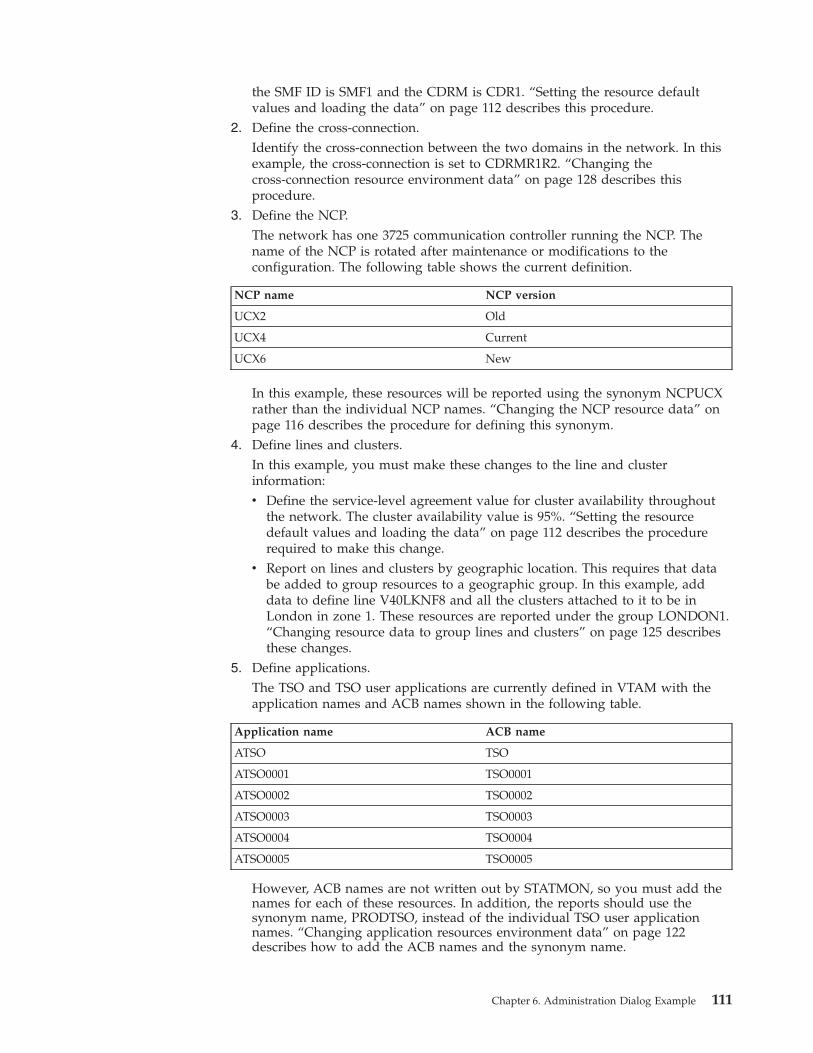
the SMF ID is SMF1 and the CDRM is CDR1. “Setting the resource default
values and loading the data” on page 112 describes this procedure.
2. Define the cross-connection.
Identify the cross-connection between the two domains in the network. In this
example, the cross-connection is set to CDRMR1R2. “Changing the
cross-connection resource environment data” on page 128 describes this
procedure.
3. Define the NCP.
The network has one 3725 communication controller running the NCP. The
name of the NCP is rotated after maintenance or modifications to the
configuration. The following table shows the current definition.
NCP name NCP version
UCX2 Old
UCX4 Current
UCX6 New
In this example, these resources will be reported using the synonym NCPUCX
rather than the individual NCP names. “Changing the NCP resource data” on
page 116 describes the procedure for defining this synonym.
4. Define lines and clusters.
In this example, you must make these changes to the line and cluster
information:
v Define the service-level agreement value for cluster availability throughout
the network. The cluster availability value is 95%. “Setting the resource
default values and loading the data” on page 112 describes the procedure
required to make this change.
v Report on lines and clusters by geographic location. This requires that data
be added to group resources to a geographic group. In this example, add
data to define line V40LKNF8 and all the clusters attached to it to be in
London in zone 1. These resources are reported under the group LONDON1.
“Changing resource data to group lines and clusters” on page 125 describes
these changes.5. Define applications.
The TSO and TSO user applications are currently defined in VTAM with the
application names and ACB names shown in the following table.
Application name ACB name
ATSO TSO
ATSO0001 TSO0001
ATSO0002 TSO0002
ATSO0003 TSO0003
ATSO0004 TSO0004
ATSO0005 TSO0005
However, ACB names are not written out by STATMON, so you must add the
names for each of these resources. In addition, the reports should use the
synonym name, PRODTSO, instead of the individual TSO user application
names. “Changing application resources environment data” on page 122
describes how to add the ACB names and the synonym name.
Chapter 6. Administration Dialog Example 111
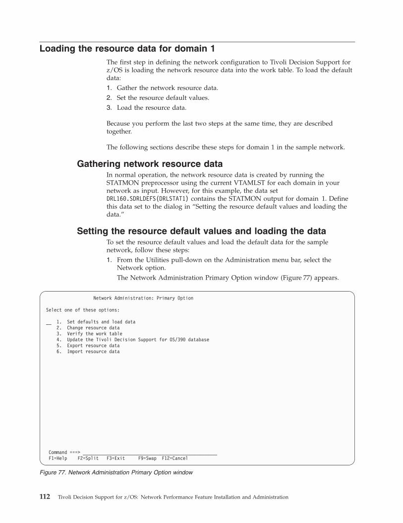
Loading the resource data for domain 1
The first step in defining the network configuration to Tivoli Decision Support for
z/OS is loading the network resource data into the work table. To load the default
data:
1. Gather the network resource data.
2. Set the resource default values.
3. Load the resource data.
Because you perform the last two steps at the same time, they are described
together.
The following sections describe these steps for domain 1 in the sample network.
Gathering network resource data
In normal operation, the network resource data is created by running the
STATMON preprocessor using the current VTAMLST for each domain in your
network as input. However, for this example, the data set
DRL160.SDRLDEFS(DRLSTAT1) contains the STATMON output for domain 1. Define
this data set to the dialog in “Setting the resource default values and loading the
data.”
Setting the resource default values and loading the data
To set the resource default values and load the default data for the sample
network, follow these steps:
1. From the Utilities pull-down on the Administration menu bar, select the
Network option.
The Network Administration Primary Option window (Figure 77) appears.
Network Administration: Primary Option
Select one of these options:
__ 1. Set defaults and load data
2. Change resource data
3. Verify the work table
4. Update the Tivoli Decision Support for OS/390 database
5. Export resource data
6. Import resource data
Command ===> ___________________________________________________
F1=Help F2=Split F3=Exit F9=Swap F12=Cancel
Figure 77. Network Administration Primary Option window
112 Tivoli Decision Support for z/OS: Network Performance Feature Installation and Administration
2. Type 1 and press Enter to set the resource defaults and load the default data.
The Set Defaults and Load Data window (Figure 78) appears. The window lists
the systems defined to the .
3. Type 1 beside the **NEW** entry and press Enter.
The Edit Resource Defaults window appears (Figure 79 on page 114),
containing default values.
Set Defaults and Load Data ROW 1 TO 2 OF 2
Type an action code beside the system ID you want to select.
1 - Edit 2 - Delete 1 (for **NEW**) - Create
Action System ID System description
_ **NEW**
Command ===> ______________________________________________________________
F1=Help F2=Split F3=Exit F7=Bkwd F8=Fwd F9=Swap F12=Cancel
Figure 78. List of defined systems
Chapter 6. Administration Dialog Example 113
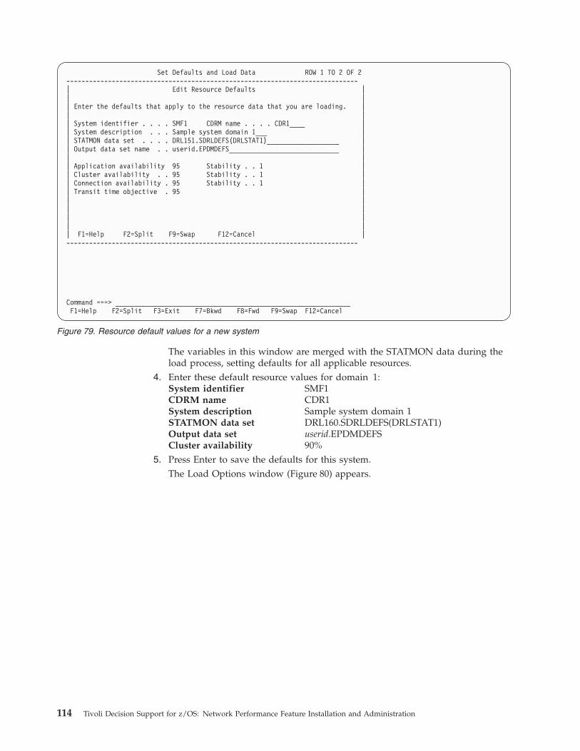
The variables in this window are merged with the STATMON data during the
load process, setting defaults for all applicable resources.
4. Enter these default resource values for domain 1:
System identifier SMF1
CDRM name CDR1
System description Sample system domain 1
STATMON data set DRL160.SDRLDEFS(DRLSTAT1)
Output data set userid.EPDMDEFS
Cluster availability 90%5. Press Enter to save the defaults for this system.
The Load Options window (Figure 80) appears.
Set Defaults and Load Data ROW 1 TO 2 OF 2
-----------------------------------------------------------------------------
| Edit Resource Defaults |
| |
| Enter the defaults that apply to the resource data that you are loading. |
| |
| System identifier . . . . SMF1 CDRM name . . . . CDR1____ |
| System description . . . Sample system domain 1___ |
| STATMON data set . . . . DRL151.SDRLDEFS(DRLSTAT1)___________________ |
| Output data set name . . userid.EPDMDEFS_____________________________ |
| |
| Application availability 95 Stability . . 1 |
| Cluster availability . . 95 Stability . . 1 |
| Connection availability . 95 Stability . . 1 |
| Transit time objective . 95 |
| |
| |
| |
| |
| F1=Help F2=Split F9=Swap F12=Cancel |
-----------------------------------------------------------------------------
Command ===> ______________________________________________________________
F1=Help F2=Split F3=Exit F7=Bkwd F8=Fwd F9=Swap F12=Cancel
Figure 79. Resource default values for a new system
114 Tivoli Decision Support for z/OS: Network Performance Feature Installation and Administration
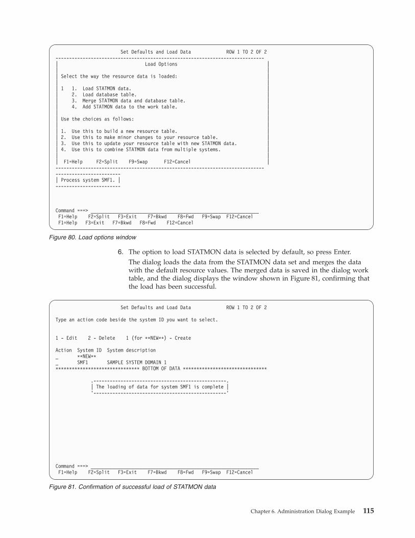
6. The option to load STATMON data is selected by default, so press Enter.
The dialog loads the data from the STATMON data set and merges the data
with the default resource values. The merged data is saved in the dialog work
table, and the dialog displays the window shown in Figure 81, confirming that
the load has been successful.
Set Defaults and Load Data ROW 1 TO 2 OF 2
-----------------------------------------------------------------------------
| Load Options |
| |
| Select the way the resource data is loaded: |
| |
| 1 1. Load STATMON data. |
| 2. Load database table. |
| 3. Merge STATMON data and database table. |
| 4. Add STATMON data to the work table. |
| |
| Use the choices as follows: |
| |
| 1. Use this to build a new resource table. |
| 2. Use this to make minor changes to your resource table. |
| 3. Use this to update your resource table with new STATMON data. |
| 4. Use this to combine STATMON data from multiple systems. |
| |
| F1=Help F2=Split F9=Swap F12=Cancel |
-----------------------------------------------------------------------------
------------------------
| Process system SMF1. |
------------------------
Command ===> ______________________________________________________________
F1=Help F2=Split F3=Exit F7=Bkwd F8=Fwd F9=Swap F12=Cancel
F1=Help F3=Exit F7=Bkwd F8=Fwd F12=Cancel
Figure 80. Load options window
Set Defaults and Load Data ROW 1 TO 2 OF 2
Type an action code beside the system ID you want to select.
1 - Edit 2 - Delete 1 (for **NEW**) - Create
Action System ID System description
_ **NEW**
_ SMF1 SAMPLE SYSTEM DOMAIN 1
******************************* BOTTOM OF DATA *******************************
.-------------------------------------------------.
| The loading of data for system SMF1 is complete |
’-------------------------------------------------’
Command ===> ______________________________________________________________
F1=Help F2=Split F3=Exit F7=Bkwd F8=Fwd F9=Swap F12=Cancel
Figure 81. Confirmation of successful load of STATMON data
Chapter 6. Administration Dialog Example 115
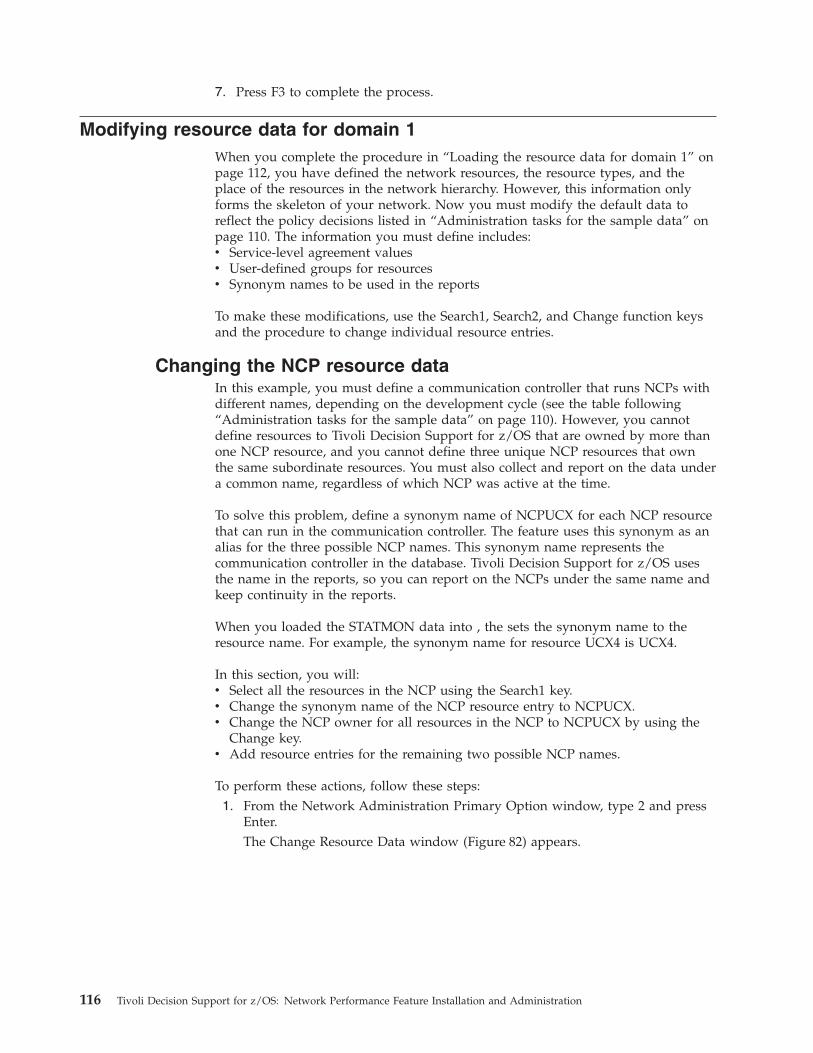
7. Press F3 to complete the process.
Modifying resource data for domain 1
When you complete the procedure in “Loading the resource data for domain 1” on
page 112, you have defined the network resources, the resource types, and the
place of the resources in the network hierarchy. However, this information only
forms the skeleton of your network. Now you must modify the default data to
reflect the policy decisions listed in “Administration tasks for the sample data” on
page 110. The information you must define includes:
v Service-level agreement values
v User-defined groups for resources
v Synonym names to be used in the reports
To make these modifications, use the Search1, Search2, and Change function keys
and the procedure to change individual resource entries.
Changing the NCP resource data
In this example, you must define a communication controller that runs NCPs with
different names, depending on the development cycle (see the table following
“Administration tasks for the sample data” on page 110). However, you cannot
define resources to Tivoli Decision Support for z/OS that are owned by more than
one NCP resource, and you cannot define three unique NCP resources that own
the same subordinate resources. You must also collect and report on the data under
a common name, regardless of which NCP was active at the time.
To solve this problem, define a synonym name of NCPUCX for each NCP resource
that can run in the communication controller. The feature uses this synonym as an
alias for the three possible NCP names. This synonym name represents the
communication controller in the database. Tivoli Decision Support for z/OS uses
the name in the reports, so you can report on the NCPs under the same name and
keep continuity in the reports.
When you loaded the STATMON data into , the sets the synonym name to the
resource name. For example, the synonym name for resource UCX4 is UCX4.
In this section, you will:
v Select all the resources in the NCP using the Search1 key.
v Change the synonym name of the NCP resource entry to NCPUCX.
v Change the NCP owner for all resources in the NCP to NCPUCX by using the
Change key.
v Add resource entries for the remaining two possible NCP names.
To perform these actions, follow these steps:
1. From the Network Administration Primary Option window, type 2 and press
Enter.
The Change Resource Data window (Figure 82) appears.
116 Tivoli Decision Support for z/OS: Network Performance Feature Installation and Administration
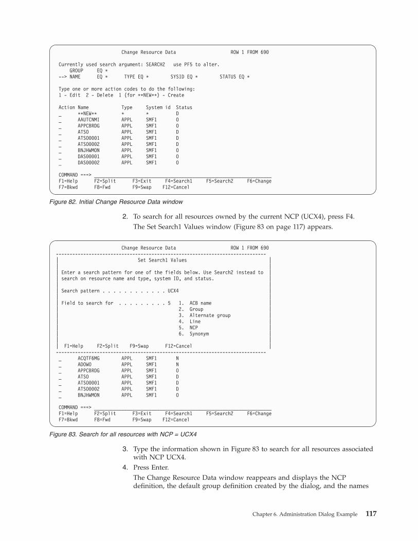
2. To search for all resources owned by the current NCP (UCX4), press F4.
The Set Search1 Values window (Figure 83 on page 117) appears.
3. Type the information shown in Figure 83 to search for all resources associated
with NCP UCX4.
4. Press Enter.
The Change Resource Data window reappears and displays the NCP
definition, the default group definition created by the dialog, and the names
Change Resource Data ROW 1 FROM 690
Currently used search argument: SEARCH2 use PF5 to alter.
GROUP EQ *
--> NAME EQ * TYPE EQ * SYSID EQ * STATUS EQ *
Type one or more action codes to do the following:
1 - Edit 2 - Delete 1 (for **NEW**) - Create
Action Name Type System id Status
_ **NEW** * * D
_ AAUTCNMI APPL SMF1 O
_ APPCBRDG APPL SMF1 O
_ ATSO APPL SMF1 D
_ ATSO0001 APPL SMF1 D
_ ATSO0002 APPL SMF1 D
_ BNJHWMON APPL SMF1 O
_ DAS00001 APPL SMF1 O
_ DAS00002 APPL SMF1 O
COMMAND ===> _________________________________________________________________
F1=Help F2=Split F3=Exit F4=Search1 F5=Search2 F6=Change
F7=Bkwd F8=Fwd F9=Swap F12=Cancel
Figure 82. Initial Change Resource Data window
Change Resource Data ROW 1 FROM 690
-----------------------------------------------------------------------------
| Set Search1 Values |
| |
| Enter a search pattern for one of the fields below. Use Search2 instead to |
| search on resource name and type, system ID, and status. |
| |
| Search pattern . . . . . . . . . . . . UCX4 |
| |
| Field to search for . . . . . . . . . 5 1. ACB name |
| 2. Group |
| 3. Alternate group |
| 4. Line |
| 5. NCP |
| 6. Synonym |
| |
| F1=Help F2=Split F9=Swap F12=Cancel |
-----------------------------------------------------------------------------
_ ACQTF6MG APPL SMF1 N
_ ADOWO APPL SMF1 N
_ APPCBRDG APPL SMF1 O
_ ATSO APPL SMF1 D
_ ATSO0001 APPL SMF1 D
_ ATSO0002 APPL SMF1 D
_ BNJHWMON APPL SMF1 O
COMMAND ===> _________________________________________________________________
F1=Help F2=Split F3=Exit F4=Search1 F5=Search2 F6=Change
F7=Bkwd F8=Fwd F9=Swap F12=Cancel
Figure 83. Search for all resources with NCP = UCX4
Chapter 6. Administration Dialog Example 117
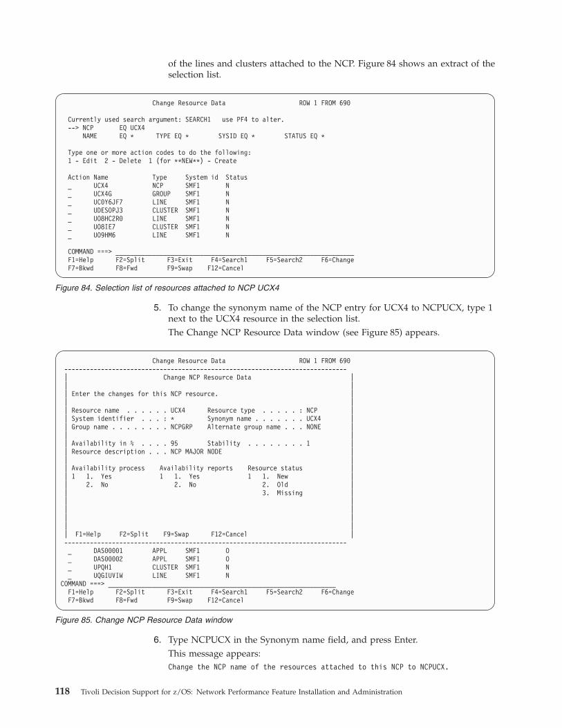
of the lines and clusters attached to the NCP. Figure 84 shows an extract of the
selection list.
5. To change the synonym name of the NCP entry for UCX4 to NCPUCX, type 1
next to the UCX4 resource in the selection list.
The Change NCP Resource Data window (see Figure 85) appears.
6. Type NCPUCX in the Synonym name field, and press Enter.
This message appears:
Change the NCP name of the resources attached to this NCP to NCPUCX.
Change Resource Data ROW 1 FROM 690
Currently used search argument: SEARCH1 use PF4 to alter.
--> NCP EQ UCX4
NAME EQ * TYPE EQ * SYSID EQ * STATUS EQ *
Type one or more action codes to do the following:
1 - Edit 2 - Delete 1 (for **NEW**) - Create
Action Name Type System id Status
_ UCX4 NCP SMF1 N
_ UCX4G GROUP SMF1 N
_ UC0Y6JF7 LINE SMF1 N
_ UDESOPJ3 CLUSTER SMF1 N
_ UO8HC2R0 LINE SMF1 N
_ UO8IE7 CLUSTER SMF1 N
_ UO9HM6 LINE SMF1 N
COMMAND ===> _________________________________________________________________
F1=Help F2=Split F3=Exit F4=Search1 F5=Search2 F6=Change
F7=Bkwd F8=Fwd F9=Swap F12=Cancel
Figure 84. Selection list of resources attached to NCP UCX4
Change Resource Data ROW 1 FROM 690
-----------------------------------------------------------------------------
| Change NCP Resource Data |
| |
| Enter the changes for this NCP resource. |
| |
| Resource name . . . . . . UCX4 Resource type . . . . . : NCP |
| System identifier . . . : * Synonym name . . . . . . . UCX4 |
| Group name . . . . . . . . NCPGRP Alternate group name . . . NONE |
| |
| Availability in % . . . . 95 Stability . . . . . . . . 1 |
| Resource description . . . NCP MAJOR NODE |
| |
| Availability process Availability reports Resource status |
| 1 1. Yes 1 1. Yes 1 1. New |
| 2. No 2. No 2. Old |
| 3. Missing |
| |
| |
| |
| |
| F1=Help F2=Split F9=Swap F12=Cancel |
-----------------------------------------------------------------------------
_ DAS00001 APPL SMF1 O
_ DAS00002 APPL SMF1 O
_ UPQH1 CLUSTER SMF1 N
_ UQGIUVIW LINE SMF1 N
COMMAND ===> ______________________________________________________________
F1=Help F2=Split F3=Exit F4=Search1 F5=Search2 F6=Change
F7=Bkwd F8=Fwd F9=Swap F12=Cancel
Figure 85. Change NCP Resource Data window
118 Tivoli Decision Support for z/OS: Network Performance Feature Installation and Administration
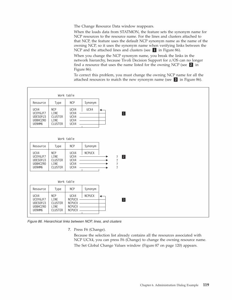
The Change Resource Data window reappears.
When the loads data from STATMON, the feature sets the synonym name for
NCP resources to the resource name. For the lines and clusters attached to
that NCP, the feature uses the default NCP synonym name as the name of the
owning NCP, so it uses the synonym name when verifying links between the
NCP and the attached lines and clusters (see �1� in Figure 86).
When you change the NCP synonym name, you break the links in the
network hierarchy, because Tivoli Decision Support for z/OS can no longer
find a resource that uses the name listed for the owning NCP (see �2� in
Figure 86).
To correct this problem, you must change the owning NCP name for all the
attached resources to match the new synonym name (see �3� in Figure 86).
7. Press F6 (Change).
Because the selection list already contains all the resources associated with
NCP UCX4, you can press F6 (Change) to change the owning resource name.
The Set Global Change Values window (Figure 87 on page 120) appears.
Synonym
Synonym
Synonym
UCX4UC0Y6JF7UDESOPJ3U08HC2R0U09HM6
UCX4UC0Y6JF7UDESOPJ3U08HC2R0U09HM6
UCX4UC0Y6JF7UDESOPJ3U08HC2R0U09HM6
NCPLINECLUSTERLINECLUSTER
NCPLINECLUSTERLINECLUSTER
NCPLINECLUSTERLINECLUSTER
UCX4UCX4UCX4UCX4UCX4
UCX4NCPUCXNCPUCXNCPUCXNCPUCX
UCX4UCX4UCX4UCX4UCX4
????
UCX4
NCPUCX
NCPUCX
Resource
Resource
Resource
Type
Type
Type
Work table
Work table
Work table
NCP
NCP
NCP
1
3
2
Figure 86. Hierarchical links between NCP, lines, and clusters
Chapter 6. Administration Dialog Example 119
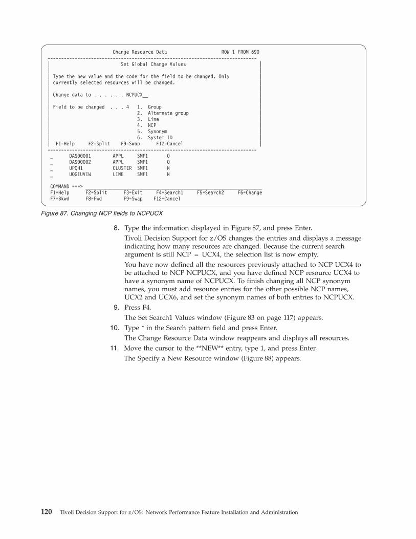
8. Type the information displayed in Figure 87, and press Enter.
Tivoli Decision Support for z/OS changes the entries and displays a message
indicating how many resources are changed. Because the current search
argument is still NCP = UCX4, the selection list is now empty.
You have now defined all the resources previously attached to NCP UCX4 to
be attached to NCP NCPUCX, and you have defined NCP resource UCX4 to
have a synonym name of NCPUCX. To finish changing all NCP synonym
names, you must add resource entries for the other possible NCP names,
UCX2 and UCX6, and set the synonym names of both entries to NCPUCX.
9. Press F4.
The Set Search1 Values window (Figure 83 on page 117) appears.
10. Type * in the Search pattern field and press Enter.
The Change Resource Data window reappears and displays all resources.
11. Move the cursor to the **NEW** entry, type 1, and press Enter.
The Specify a New Resource window (Figure 88) appears.
Change Resource Data ROW 1 FROM 690
-----------------------------------------------------------------------------
| Set Global Change Values |
| |
| Type the new value and the code for the field to be changed. Only |
| currently selected resources will be changed. |
| |
| Change data to . . . . . . NCPUCX__ |
| |
| Field to be changed . . . 4 1. Group |
| 2. Alternate group |
| 3. Line |
| 4. NCP |
| 5. Synonym |
| 6. System ID |
| F1=Help F2=Split F9=Swap F12=Cancel |
-----------------------------------------------------------------------------
_ DAS00001 APPL SMF1 O
_ DAS00002 APPL SMF1 O
_ UPQH1 CLUSTER SMF1 N
_ UQGIUVIW LINE SMF1 N
COMMAND ===> _________________________________________________________________
F1=Help F2=Split F3=Exit F4=Search1 F5=Search2 F6=Change
F7=Bkwd F8=Fwd F9=Swap F12=Cancel
Figure 87. Changing NCP fields to NCPUCX
120 Tivoli Decision Support for z/OS: Network Performance Feature Installation and Administration
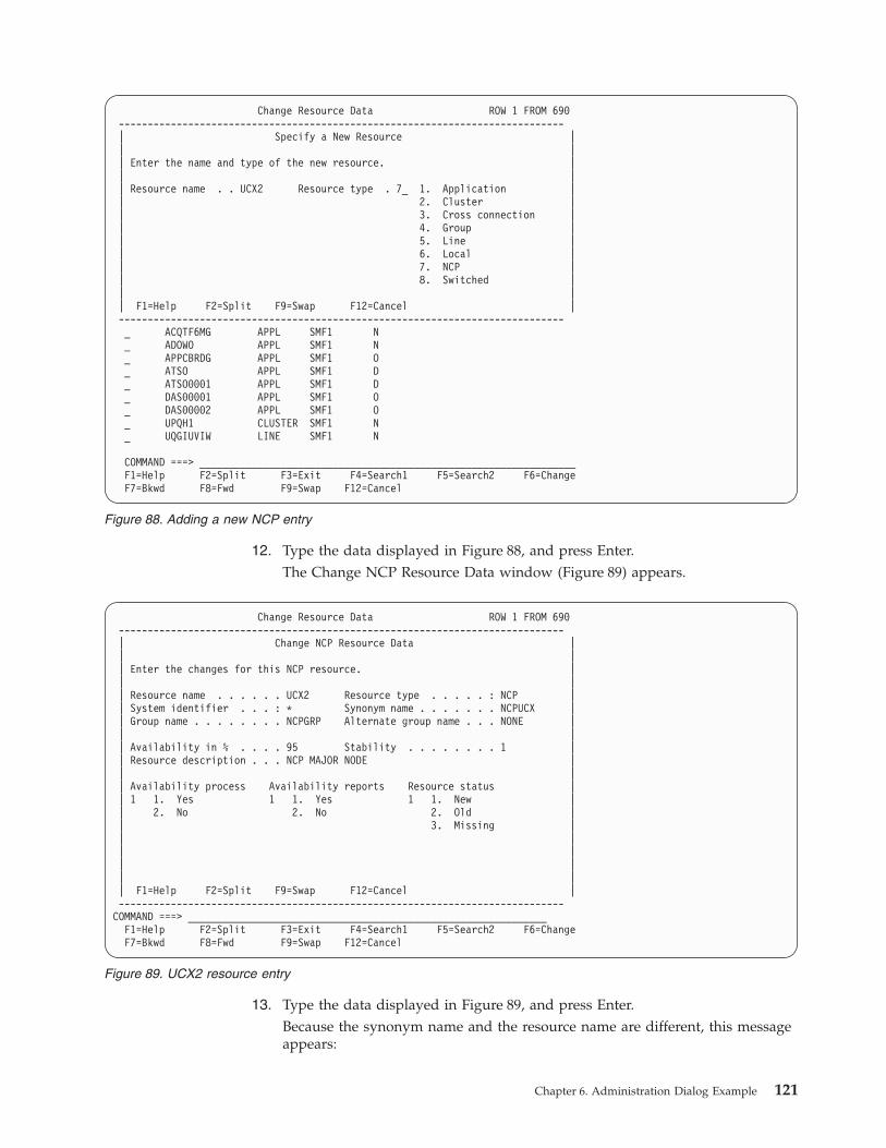
12. Type the data displayed in Figure 88, and press Enter.
The Change NCP Resource Data window (Figure 89) appears.
13. Type the data displayed in Figure 89, and press Enter.
Because the synonym name and the resource name are different, this message
appears:
Change Resource Data ROW 1 FROM 690
-----------------------------------------------------------------------------
| Specify a New Resource |
| |
| Enter the name and type of the new resource. |
| |
| Resource name . . UCX2 Resource type . 7_ 1. Application |
| 2. Cluster |
| 3. Cross connection |
| 4. Group |
| 5. Line |
| 6. Local |
| 7. NCP |
| 8. Switched |
| |
| F1=Help F2=Split F9=Swap F12=Cancel |
-----------------------------------------------------------------------------
_ ACQTF6MG APPL SMF1 N
_ ADOWO APPL SMF1 N
_ APPCBRDG APPL SMF1 O
_ ATSO APPL SMF1 D
_ ATSO0001 APPL SMF1 D
_ DAS00001 APPL SMF1 O
_ DAS00002 APPL SMF1 O
_ UPQH1 CLUSTER SMF1 N
_ UQGIUVIW LINE SMF1 N
COMMAND ===> _________________________________________________________________
F1=Help F2=Split F3=Exit F4=Search1 F5=Search2 F6=Change
F7=Bkwd F8=Fwd F9=Swap F12=Cancel
Figure 88. Adding a new NCP entry
Change Resource Data ROW 1 FROM 690
-----------------------------------------------------------------------------
| Change NCP Resource Data |
| |
| Enter the changes for this NCP resource. |
| |
| Resource name . . . . . . UCX2 Resource type . . . . . : NCP |
| System identifier . . . : * Synonym name . . . . . . . NCPUCX |
| Group name . . . . . . . . NCPGRP Alternate group name . . . NONE |
| |
| Availability in % . . . . 95 Stability . . . . . . . . 1 |
| Resource description . . . NCP MAJOR NODE |
| |
| Availability process Availability reports Resource status |
| 1 1. Yes 1 1. Yes 1 1. New |
| 2. No 2. No 2. Old |
| 3. Missing |
| |
| |
| |
| |
| F1=Help F2=Split F9=Swap F12=Cancel |
-----------------------------------------------------------------------------
COMMAND ===> ______________________________________________________________
F1=Help F2=Split F3=Exit F4=Search1 F5=Search2 F6=Change
F7=Bkwd F8=Fwd F9=Swap F12=Cancel
Figure 89. UCX2 resource entry
Chapter 6. Administration Dialog Example 121
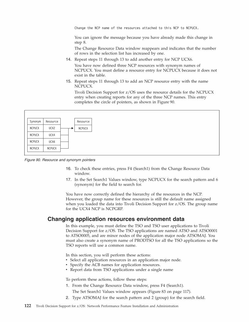
Change the NCP name of the resources attached to this NCP to NCPUCX.
You can ignore the message because you have already made this change in
step 8.
The Change Resource Data window reappears and indicates that the number
of rows in the selection list has increased by one.
14. Repeat steps 11 through 13 to add another entry for NCP UCX6.
You have now defined three NCP resources with synonym names of
NCPUCX. You must define a resource entry for NCPUCX because it does not
exist in the table.
15. Repeat steps 11 through 13 to add an NCP resource entry with the name
NCPUCX.
Tivoli Decision Support for z/OS uses the resource details for the NCPUCX
entry when creating reports for any of the three NCP names. This entry
completes the circle of pointers, as shown in Figure 90.
16. To check these entries, press F4 (Search1) from the Change Resource Data
window.
17. In the Set Search1 Values window, type NCPUCX for the search pattern and 6
(synonym) for the field to search for.
You have now correctly defined the hierarchy of the resources in the NCP.
However, the group name for these resources is still the default name assigned
when you loaded the data into Tivoli Decision Support for z/OS. The group name
for the UCX4 NCP is NCPGRP.
Changing application resources environment data
In this example, you must define the TSO and TSO user applications to Tivoli
Decision Support for z/OS. The TSO applications are named ATSO and ATSO0001
to ATSO0005, and are minor nodes of the application major node ATSOMAJ. You
must also create a synonym name of PRODTSO for all the TSO applications so the
TSO reports will use a common name.
In this section, you will perform these actions:
v Select all application resources in an application major node.
v Specify the ACB names for application resources.
v Report data from TSO applications under a single name
To perform these actions, follow these steps:
1. From the Change Resource Data window, press F4 (Search1).
The Set Search1 Values window appears (Figure 83 on page 117).
2. Type ATSOMAJ for the search pattern and 2 (group) for the search field.
Synonym
NCPUCX
NCPUCX
NCPUCX
NCPUCX NCPUCX
NCPUCX
ResourceResource
UCX2
UCX4
UCX6
Figure 90. Resource and synonym pointers
122 Tivoli Decision Support for z/OS: Network Performance Feature Installation and Administration
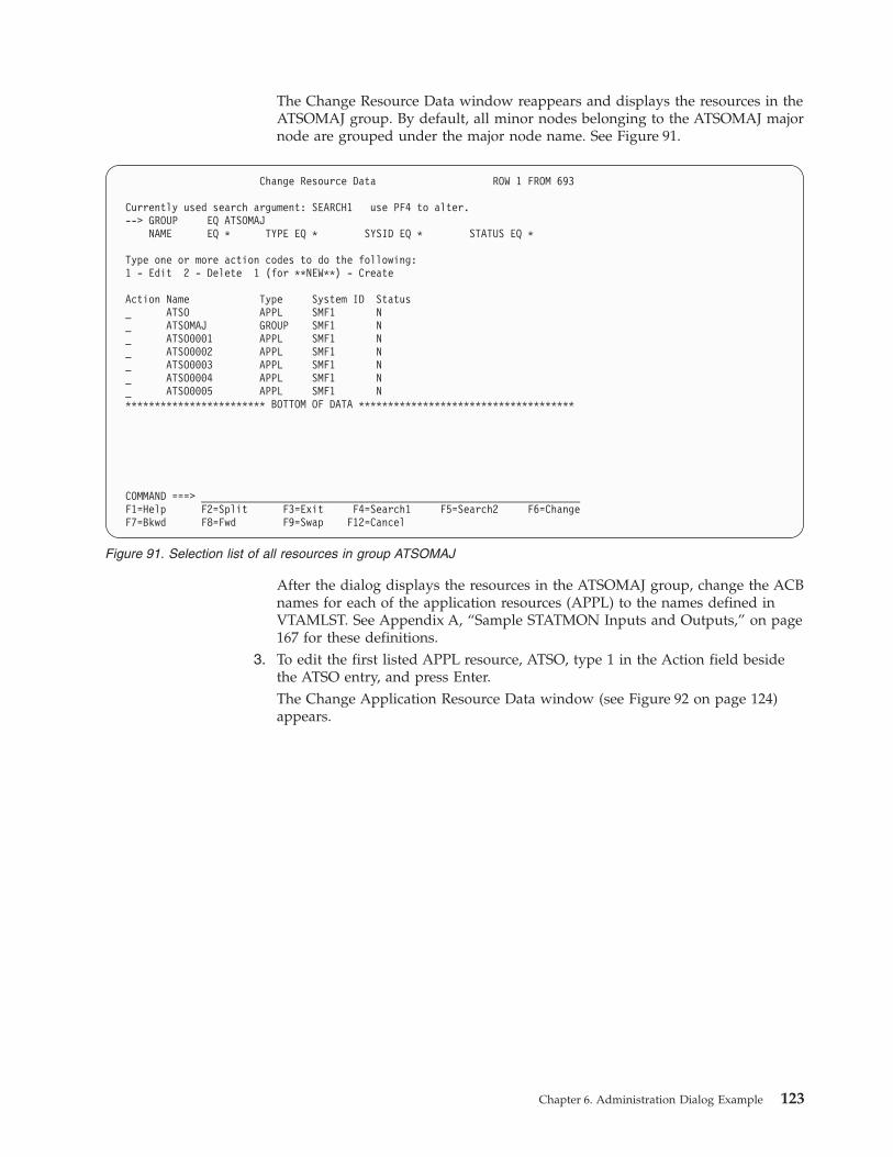
The Change Resource Data window reappears and displays the resources in the
ATSOMAJ group. By default, all minor nodes belonging to the ATSOMAJ major
node are grouped under the major node name. See Figure 91.
After the dialog displays the resources in the ATSOMAJ group, change the ACB
names for each of the application resources (APPL) to the names defined in
VTAMLST. See Appendix A, “Sample STATMON Inputs and Outputs,” on page
167 for these definitions.
3. To edit the first listed APPL resource, ATSO, type 1 in the Action field beside
the ATSO entry, and press Enter.
The Change Application Resource Data window (see Figure 92 on page 124)
appears.
Change Resource Data ROW 1 FROM 693
Currently used search argument: SEARCH1 use PF4 to alter.
--> GROUP EQ ATSOMAJ
NAME EQ * TYPE EQ * SYSID EQ * STATUS EQ *
Type one or more action codes to do the following:
1 - Edit 2 - Delete 1 (for **NEW**) - Create
Action Name Type System ID Status
_ ATSO APPL SMF1 N
_ ATSOMAJ GROUP SMF1 N
_ ATSO0001 APPL SMF1 N
_ ATSO0002 APPL SMF1 N
_ ATSO0003 APPL SMF1 N
_ ATSO0004 APPL SMF1 N
_ ATSO0005 APPL SMF1 N
************************ BOTTOM OF DATA *************************************
COMMAND ===> _________________________________________________________________
F1=Help F2=Split F3=Exit F4=Search1 F5=Search2 F6=Change
F7=Bkwd F8=Fwd F9=Swap F12=Cancel
Figure 91. Selection list of all resources in group ATSOMAJ
Chapter 6. Administration Dialog Example 123
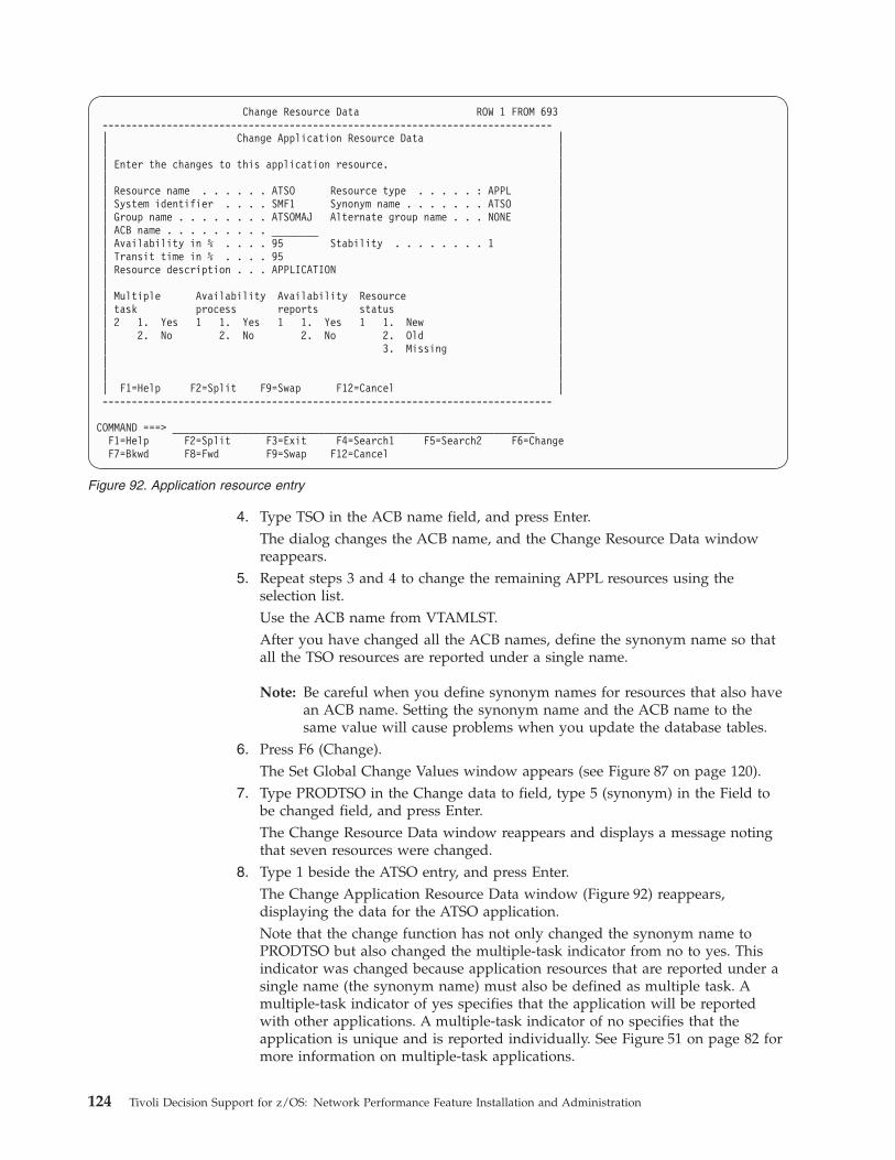
4. Type TSO in the ACB name field, and press Enter.
The dialog changes the ACB name, and the Change Resource Data window
reappears.
5. Repeat steps 3 and 4 to change the remaining APPL resources using the
selection list.
Use the ACB name from VTAMLST.
After you have changed all the ACB names, define the synonym name so that
all the TSO resources are reported under a single name.
Note: Be careful when you define synonym names for resources that also have
an ACB name. Setting the synonym name and the ACB name to the
same value will cause problems when you update the database tables.
6. Press F6 (Change).
The Set Global Change Values window appears (see Figure 87 on page 120).
7. Type PRODTSO in the Change data to field, type 5 (synonym) in the Field to
be changed field, and press Enter.
The Change Resource Data window reappears and displays a message noting
that seven resources were changed.
8. Type 1 beside the ATSO entry, and press Enter.
The Change Application Resource Data window (Figure 92) reappears,
displaying the data for the ATSO application.
Note that the change function has not only changed the synonym name to
PRODTSO but also changed the multiple-task indicator from no to yes. This
indicator was changed because application resources that are reported under a
single name (the synonym name) must also be defined as multiple task. A
multiple-task indicator of yes specifies that the application will be reported
with other applications. A multiple-task indicator of no specifies that the
application is unique and is reported individually. See Figure 51 on page 82 for
more information on multiple-task applications.
Change Resource Data ROW 1 FROM 693
-----------------------------------------------------------------------------
| Change Application Resource Data |
| |
| Enter the changes to this application resource. |
| |
| Resource name . . . . . . ATSO Resource type . . . . . : APPL |
| System identifier . . . . SMF1 Synonym name . . . . . . . ATSO |
| Group name . . . . . . . . ATSOMAJ Alternate group name . . . NONE |
| ACB name . . . . . . . . . ________ |
| Availability in % . . . . 95 Stability . . . . . . . . 1 |
| Transit time in % . . . . 95 |
| Resource description . . . APPLICATION |
| |
| Multiple Availability Availability Resource |
| task process reports status |
| 2 1. Yes 1 1. Yes 1 1. Yes 1 1. New |
| 2. No 2. No 2. No 2. Old |
| 3. Missing |
| |
| |
| F1=Help F2=Split F9=Swap F12=Cancel |
-----------------------------------------------------------------------------
COMMAND ===> ______________________________________________________________
F1=Help F2=Split F3=Exit F4=Search1 F5=Search2 F6=Change
F7=Bkwd F8=Fwd F9=Swap F12=Cancel
Figure 92. Application resource entry
124 Tivoli Decision Support for z/OS: Network Performance Feature Installation and Administration
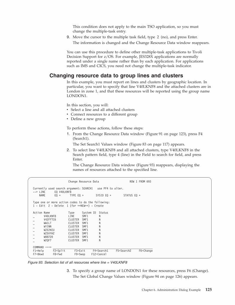
This condition does not apply to the main TSO application, so you must
change the multiple-task entry.
9. Move the cursor to the multiple task field, type 2 (no), and press Enter.
The information is changed and the Change Resource Data window reappears.
You can use this procedure to define other multiple-task applications to Tivoli
Decision Support for z/OS. For example, JES328X applications are normally
reported under a single name rather than by each application. For applications
such as IMS and CICS, you need not change the multiple-task indicator.
Changing resource data to group lines and clusters
In this example, you must report on lines and clusters by geographic location. In
particular, you want to specify that line V40LKNF8 and the attached clusters are in
London in zone 1, and that these resources will be reported using the group name
LONDON1.
In this section, you will:
v Select a line and all attached clusters
v Connect resources to a different group
v Define a new group
To perform these actions, follow these steps:
1. From the Change Resource Data window (Figure 91 on page 123), press F4
(Search1).
The Set Search1 Values window (Figure 83 on page 117) appears.
2. To select line V40LKNF8 and all attached clusters, type V40LKNF8 in the
Search pattern field, type 4 (line) in the Field to search for field, and press
Enter.
The Change Resource Data window (Figure 93) reappears, displaying the
names of resources attached to the specified line.
3. To specify a group name of LONDON1 for these resources, press F6 (Change).
The Set Global Change Values window (Figure 94 on page 126) appears.
Change Resource Data ROW 1 FROM 693
Currently used search argument: SEARCH1 use PF4 to alter.
--> LINE EQ V40LKNF8
NAME EQ * TYPE EQ * SYSID EQ * STATUS EQ *
Type one or more action codes to do the following:
1 - Edit 2 - Delete 1 (for **NEW**) - Create
Action Name Type System ID Status
_ V40LKNF8 LINE SMF1 N
_ V42FFTC6 CLUSTER SMF1 N
_ WW1LT CLUSTER SMF1 N
_ WYINN CLUSTER SMF1 N
_ WZE2KEU CLUSTER SMF1 N
_ WZ5VYHZ CLUSTER SMF1 N
_ W08720 CLUSTER SMF1 N
_ W2QF7 CLUSTER SMF1 N
COMMAND ===> _________________________________________________________________
F1=Help F2=Split F3=Exit F4=Search1 F5=Search2 F6=Change
F7=Bkwd F8=Fwd F9=Swap F12=Cancel
Figure 93. Selection list of all resources where line = V40LKNF8
Chapter 6. Administration Dialog Example 125
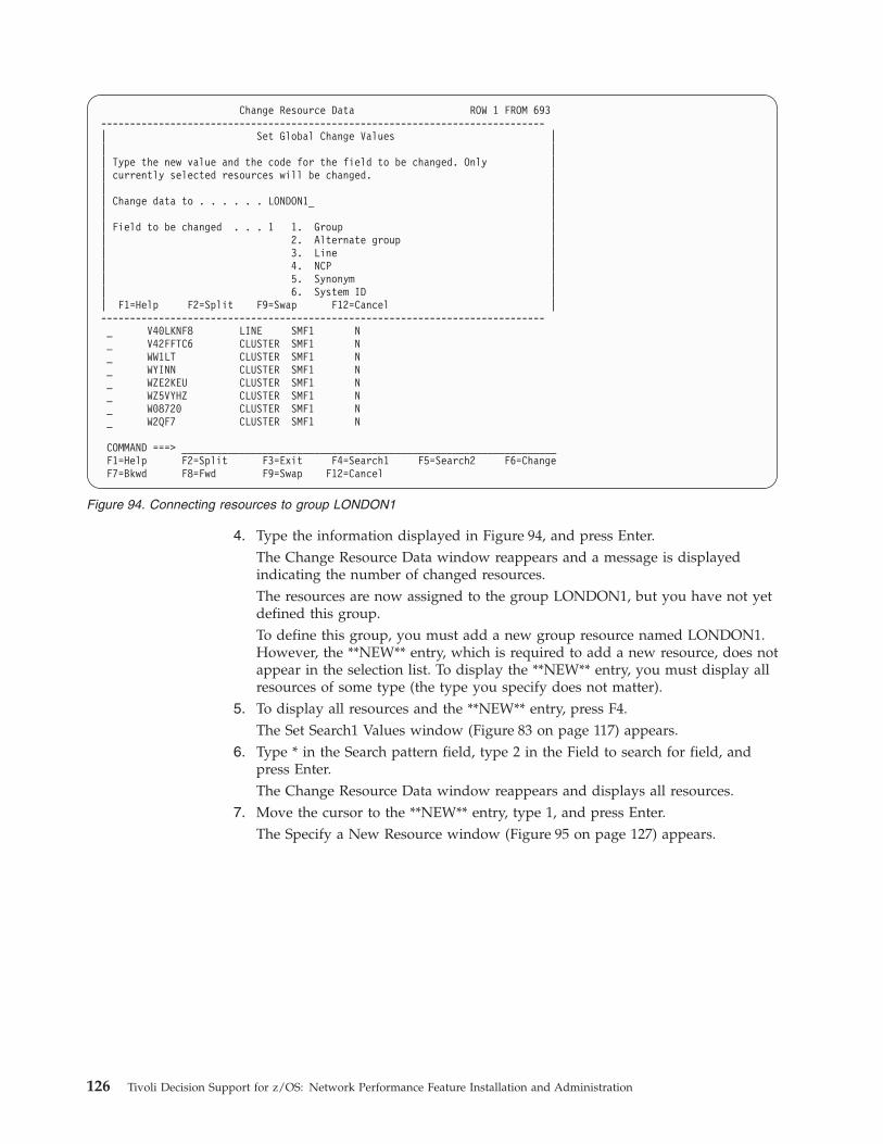
4. Type the information displayed in Figure 94, and press Enter.
The Change Resource Data window reappears and a message is displayed
indicating the number of changed resources.
The resources are now assigned to the group LONDON1, but you have not yet
defined this group.
To define this group, you must add a new group resource named LONDON1.
However, the **NEW** entry, which is required to add a new resource, does not
appear in the selection list. To display the **NEW** entry, you must display all
resources of some type (the type you specify does not matter).
5. To display all resources and the **NEW** entry, press F4.
The Set Search1 Values window (Figure 83 on page 117) appears.
6. Type * in the Search pattern field, type 2 in the Field to search for field, and
press Enter.
The Change Resource Data window reappears and displays all resources.
7. Move the cursor to the **NEW** entry, type 1, and press Enter.
The Specify a New Resource window (Figure 95 on page 127) appears.
Change Resource Data ROW 1 FROM 693
-----------------------------------------------------------------------------
| Set Global Change Values |
| |
| Type the new value and the code for the field to be changed. Only |
| currently selected resources will be changed. |
| |
| Change data to . . . . . . LONDON1_ |
| |
| Field to be changed . . . 1 1. Group |
| 2. Alternate group |
| 3. Line |
| 4. NCP |
| 5. Synonym |
| 6. System ID |
| F1=Help F2=Split F9=Swap F12=Cancel |
-----------------------------------------------------------------------------
_ V40LKNF8 LINE SMF1 N
_ V42FFTC6 CLUSTER SMF1 N
_ WW1LT CLUSTER SMF1 N
_ WYINN CLUSTER SMF1 N
_ WZE2KEU CLUSTER SMF1 N
_ WZ5VYHZ CLUSTER SMF1 N
_ W08720 CLUSTER SMF1 N
_ W2QF7 CLUSTER SMF1 N
COMMAND ===> _________________________________________________________________
F1=Help F2=Split F3=Exit F4=Search1 F5=Search2 F6=Change
F7=Bkwd F8=Fwd F9=Swap F12=Cancel
Figure 94. Connecting resources to group LONDON1
126 Tivoli Decision Support for z/OS: Network Performance Feature Installation and Administration
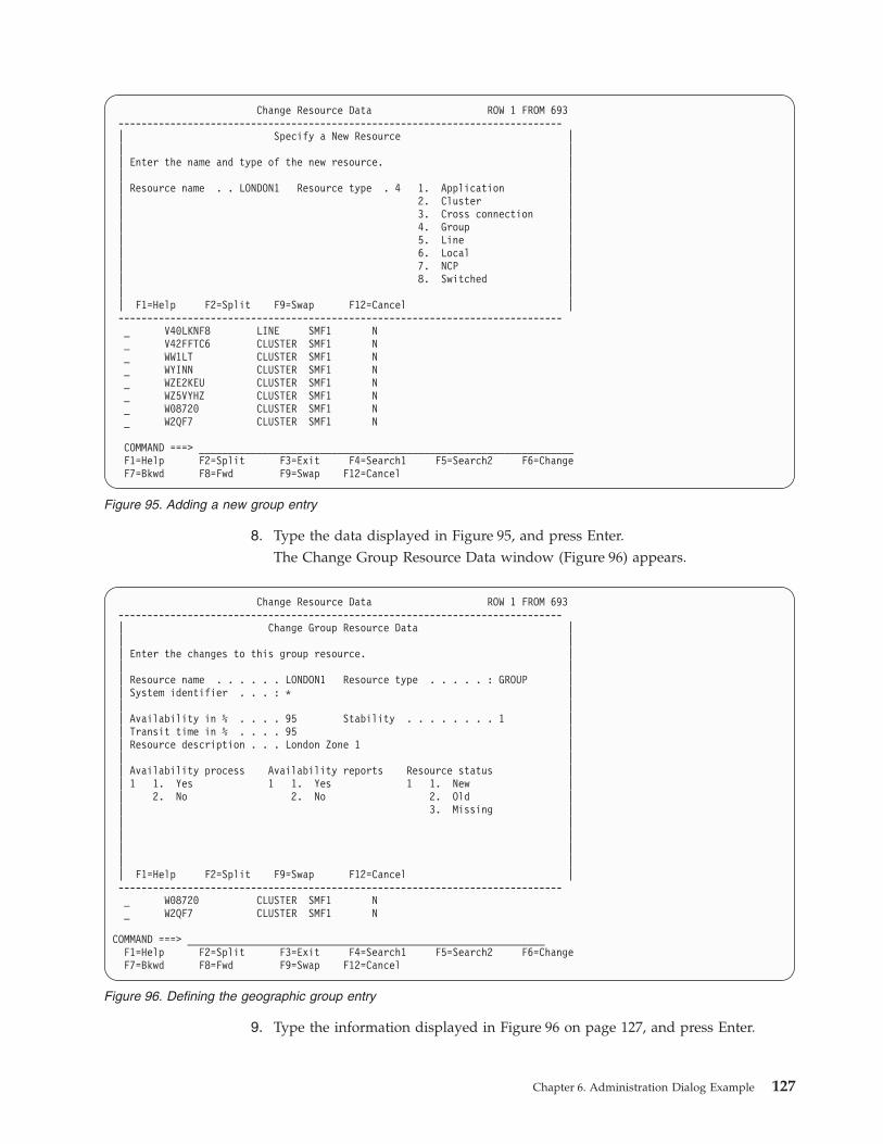
8. Type the data displayed in Figure 95, and press Enter.
The Change Group Resource Data window (Figure 96) appears.
9. Type the information displayed in Figure 96 on page 127, and press Enter.
Change Resource Data ROW 1 FROM 693
-----------------------------------------------------------------------------
| Specify a New Resource |
| |
| Enter the name and type of the new resource. |
| |
| Resource name . . LONDON1 Resource type . 4 1. Application |
| 2. Cluster |
| 3. Cross connection |
| 4. Group |
| 5. Line |
| 6. Local |
| 7. NCP |
| 8. Switched |
| |
| F1=Help F2=Split F9=Swap F12=Cancel |
-----------------------------------------------------------------------------
_ V40LKNF8 LINE SMF1 N
_ V42FFTC6 CLUSTER SMF1 N
_ WW1LT CLUSTER SMF1 N
_ WYINN CLUSTER SMF1 N
_ WZE2KEU CLUSTER SMF1 N
_ WZ5VYHZ CLUSTER SMF1 N
_ W08720 CLUSTER SMF1 N
_ W2QF7 CLUSTER SMF1 N
COMMAND ===> _________________________________________________________________
F1=Help F2=Split F3=Exit F4=Search1 F5=Search2 F6=Change
F7=Bkwd F8=Fwd F9=Swap F12=Cancel
Figure 95. Adding a new group entry
Change Resource Data ROW 1 FROM 693
-----------------------------------------------------------------------------
| Change Group Resource Data |
| |
| Enter the changes to this group resource. |
| |
| Resource name . . . . . . LONDON1 Resource type . . . . . : GROUP |
| System identifier . . . : * |
| |
| Availability in % . . . . 95 Stability . . . . . . . . 1 |
| Transit time in % . . . . 95 |
| Resource description . . . London Zone 1 |
| |
| Availability process Availability reports Resource status |
| 1 1. Yes 1 1. Yes 1 1. New |
| 2. No 2. No 2. Old |
| 3. Missing |
| |
| |
| |
| |
| F1=Help F2=Split F9=Swap F12=Cancel |
-----------------------------------------------------------------------------
_ W08720 CLUSTER SMF1 N
_ W2QF7 CLUSTER SMF1 N
COMMAND ===> ______________________________________________________________
F1=Help F2=Split F3=Exit F4=Search1 F5=Search2 F6=Change
F7=Bkwd F8=Fwd F9=Swap F12=Cancel
Figure 96. Defining the geographic group entry
Chapter 6. Administration Dialog Example 127
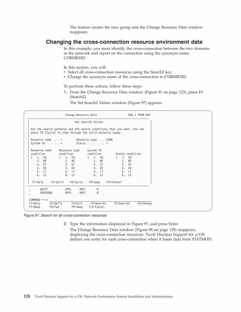
The feature creates the new group and the Change Resource Data window
reappears.
Changing the cross-connection resource environment data
In this example, you must identify the cross-connection between the two domains
in the network and report on the connection using the synonym name
CDRMR1R2.
In this section, you will:
v Select all cross-connection resources using the Search2 key.
v Change the synonym name of the cross-connection to CDRMR1R2.
To perform these actions, follow these steps:
1. From the Change Resource Data window (Figure 91 on page 123), press F5
(Search2).
The Set Search2 Values window (Figure 97) appears.
2. Type the information displayed in Figure 97, and press Enter.
The Change Resource Data window (Figure 98 on page 129) reappears,
displaying the cross-connection resources. Tivoli Decision Support for z/OS
defines one entry for each cross-connection when it loads data from STATMON.
Change Resource Data ROW 1 FROM 694
-----------------------------------------------------------------------------
| Set Search2 Values |
| |
| Set the search patterns and the search conditions that you want. You can |
| press F6 (Cycle) to step through the valid resource types. |
| |
| Resource name . . * Resource type . . CONN |
| System ID . . . . * Status . . . . . . * |
| |
| Resource name Resource type System ID |
| condition condition condition Status condition |
| 1 1. EQ 1 1. EQ 1 1. EQ 1 1. EQ |
| 2. NE 2. NE 2. NE 2. NE |
| 3. GT 3. GT 3. GT 3. GT |
| 4. GE 4. GE 4. GE 4. GE |
| 5. LT 5. LT 5. LT 5. LT |
| 6. LE 6. LE 6. LE 6. LE |
| |
| F1=Help F2=Split F6=Cycle F9=Swap F12=Cancel |
-----------------------------------------------------------------------------
_ AD77F APPL SMF1 N
_ AD8CBBOE APPL SMF1 N
COMMAND ===> _________________________________________________________________
F1=Help F2=Split F3=Exit F4=Search1 F5=Search2 F6=Change
F7=Bkwd F8=Fwd F9=Swap F12=Cancel
Figure 97. Search for all cross-connection resources
128 Tivoli Decision Support for z/OS: Network Performance Feature Installation and Administration
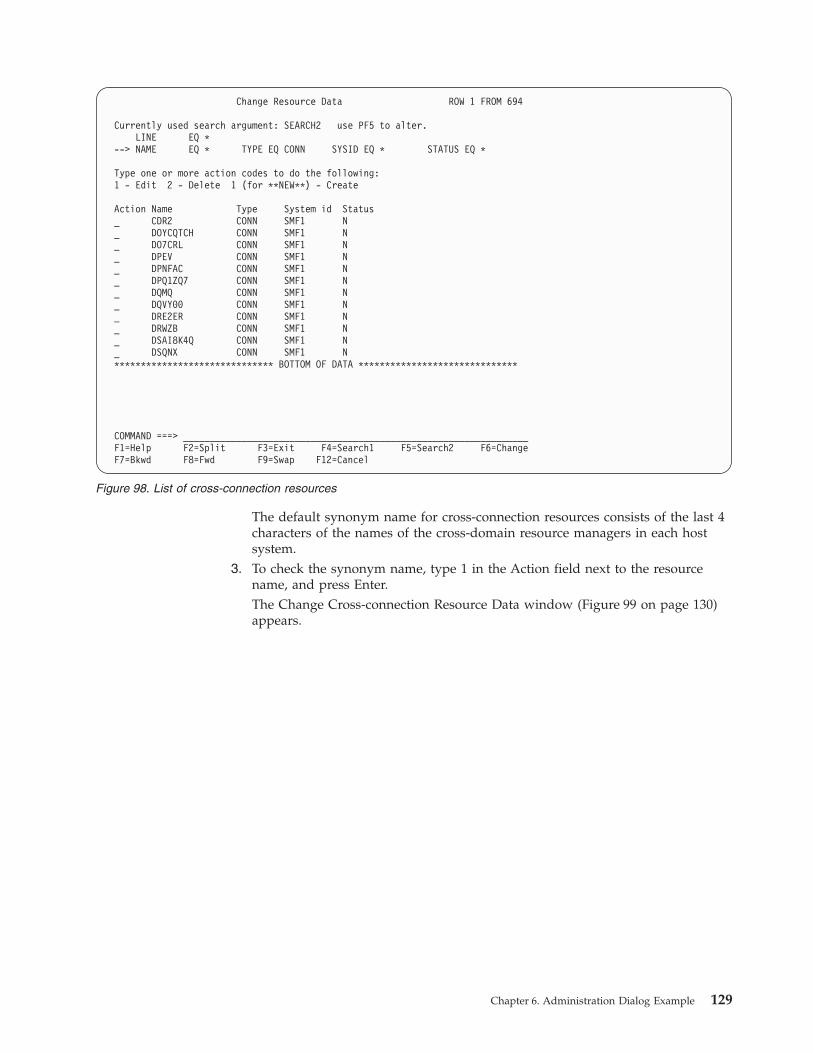
The default synonym name for cross-connection resources consists of the last 4
characters of the names of the cross-domain resource managers in each host
system.
3. To check the synonym name, type 1 in the Action field next to the resource
name, and press Enter.
The Change Cross-connection Resource Data window (Figure 99 on page 130)
appears.
Change Resource Data ROW 1 FROM 694
Currently used search argument: SEARCH2 use PF5 to alter.
LINE EQ *
--> NAME EQ * TYPE EQ CONN SYSID EQ * STATUS EQ *
Type one or more action codes to do the following:
1 - Edit 2 - Delete 1 (for **NEW**) - Create
Action Name Type System id Status
_ CDR2 CONN SMF1 N
_ DOYCQTCH CONN SMF1 N
_ DO7CRL CONN SMF1 N
_ DPEV CONN SMF1 N
_ DPNFAC CONN SMF1 N
_ DPQ1ZQ7 CONN SMF1 N
_ DQMQ CONN SMF1 N
_ DQVY00 CONN SMF1 N
_ DRE2ER CONN SMF1 N
_ DRWZB CONN SMF1 N
_ DSAI8K4Q CONN SMF1 N
_ DSQNX CONN SMF1 N
****************************** BOTTOM OF DATA ******************************
COMMAND ===> _________________________________________________________________
F1=Help F2=Split F3=Exit F4=Search1 F5=Search2 F6=Change
F7=Bkwd F8=Fwd F9=Swap F12=Cancel
Figure 98. List of cross-connection resources
Chapter 6. Administration Dialog Example 129
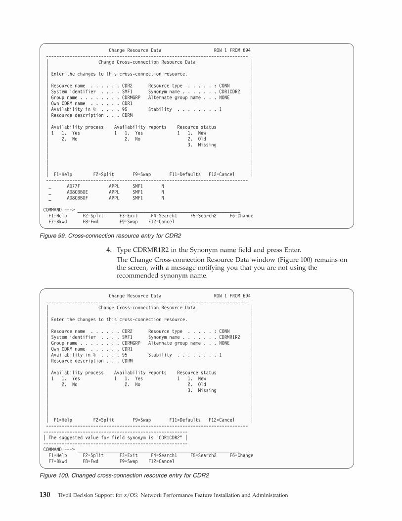
4. Type CDRMR1R2 in the Synonym name field and press Enter.
The Change Cross-connection Resource Data window (Figure 100) remains on
the screen, with a message notifying you that you are not using the
recommended synonym name.
Change Resource Data ROW 1 FROM 694
-----------------------------------------------------------------------------
| Change Cross-connection Resource Data |
| |
| Enter the changes to this cross-connection resource. |
| |
| Resource name . . . . . . CDR2 Resource type . . . . . : CONN |
| System identifier . . . . SMF1 Synonym name . . . . . . . CDR1CDR2 |
| Group name . . . . . . . . CDRMGRP Alternate group name . . . NONE |
| Own CDRM name . . . . . . CDR1 |
| Availability in % . . . . 95 Stability . . . . . . . . 1 |
| Resource description . . . CDRM |
| |
| Availability process Availability reports Resource status |
| 1 1. Yes 1 1. Yes 1 1. New |
| 2. No 2. No 2. Old |
| 3. Missing |
| |
| |
| |
| |
| F1=Help F2=Split F9=Swap F11=Defaults F12=Cancel |
-----------------------------------------------------------------------------
_ AD77F APPL SMF1 N
_ AD8CBBOE APPL SMF1 N
_ AD8CBBOF APPL SMF1 N
COMMAND ===> ______________________________________________________________
F1=Help F2=Split F3=Exit F4=Search1 F5=Search2 F6=Change
F7=Bkwd F8=Fwd F9=Swap F12=Cancel
Figure 99. Cross-connection resource entry for CDR2
Change Resource Data ROW 1 FROM 694
-----------------------------------------------------------------------------
| Change Cross-connection Resource Data |
| |
| Enter the changes to this cross-connection resource. |
| |
| Resource name . . . . . . CDR2 Resource type . . . . . : CONN |
| System identifier . . . . SMF1 Synonym name . . . . . . . CDRMR1R2 |
| Group name . . . . . . . . CDRMGRP Alternate group name . . . NONE |
| Own CDRM name . . . . . . CDR1 |
| Availability in % . . . . 95 Stability . . . . . . . . 1 |
| Resource description . . . CDRM |
| |
| Availability process Availability reports Resource status |
| 1 1. Yes 1 1. Yes 1 1. New |
| 2. No 2. No 2. Old |
| 3. Missing |
| |
| |
| |
| |
| F1=Help F2=Split F9=Swap F11=Defaults F12=Cancel |
-----------------------------------------------------------------------------
-------------------------------------------------------
| The suggested value for field synonym is "CDR1CDR2" |
-------------------------------------------------------
COMMAND ===> ______________________________________________________________
F1=Help F2=Split F3=Exit F4=Search1 F5=Search2 F6=Change
F7=Bkwd F8=Fwd F9=Swap F12=Cancel
Figure 100. Changed cross-connection resource entry for CDR2
130 Tivoli Decision Support for z/OS: Network Performance Feature Installation and Administration
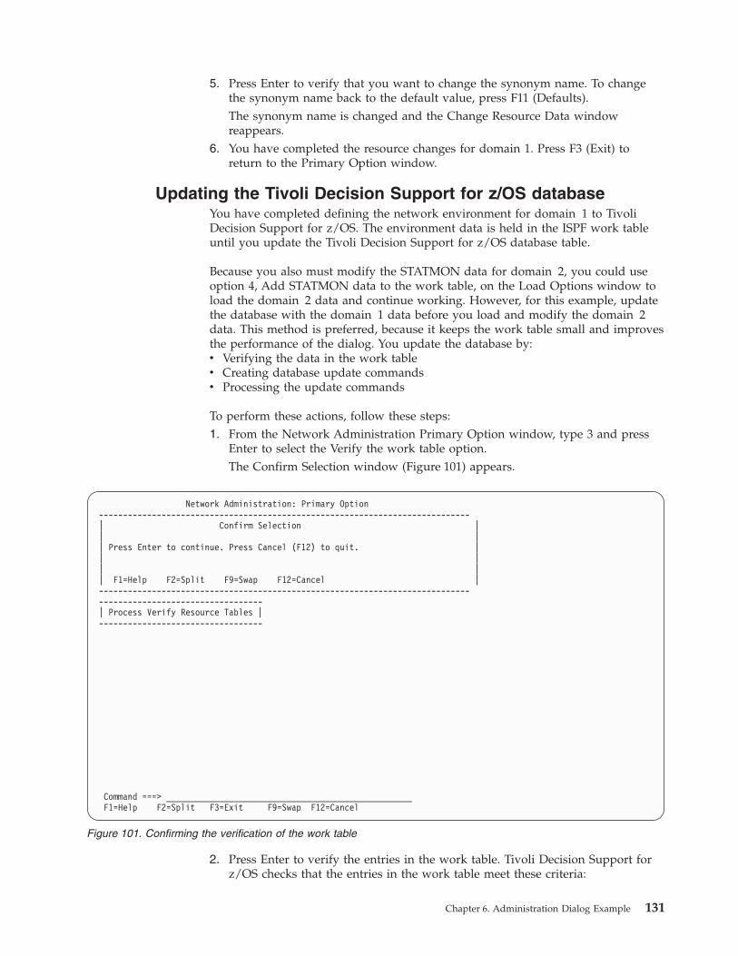
5. Press Enter to verify that you want to change the synonym name. To change
the synonym name back to the default value, press F11 (Defaults).
The synonym name is changed and the Change Resource Data window
reappears.
6. You have completed the resource changes for domain 1. Press F3 (Exit) to
return to the Primary Option window.
Updating the Tivoli Decision Support for z/OS database
You have completed defining the network environment for domain 1 to Tivoli
Decision Support for z/OS. The environment data is held in the ISPF work table
until you update the Tivoli Decision Support for z/OS database table.
Because you also must modify the STATMON data for domain 2, you could use
option 4, Add STATMON data to the work table, on the Load Options window to
load the domain 2 data and continue working. However, for this example, update
the database with the domain 1 data before you load and modify the domain 2
data. This method is preferred, because it keeps the work table small and improves
the performance of the dialog. You update the database by:
v Verifying the data in the work table
v Creating database update commands
v Processing the update commands
To perform these actions, follow these steps:
1. From the Network Administration Primary Option window, type 3 and press
Enter to select the Verify the work table option.
The Confirm Selection window (Figure 101) appears.
2. Press Enter to verify the entries in the work table. Tivoli Decision Support for
z/OS checks that the entries in the work table meet these criteria:
Network Administration: Primary Option
-----------------------------------------------------------------------------
| Confirm Selection |
| |
| Press Enter to continue. Press Cancel (F12) to quit. |
| |
| |
| F1=Help F2=Split F9=Swap F12=Cancel |
-----------------------------------------------------------------------------
----------------------------------
| Process Verify Resource Tables |
----------------------------------
Command ===> ___________________________________________________
F1=Help F2=Split F3=Exit F9=Swap F12=Cancel
Figure 101. Confirming the verification of the work table
Chapter 6. Administration Dialog Example 131
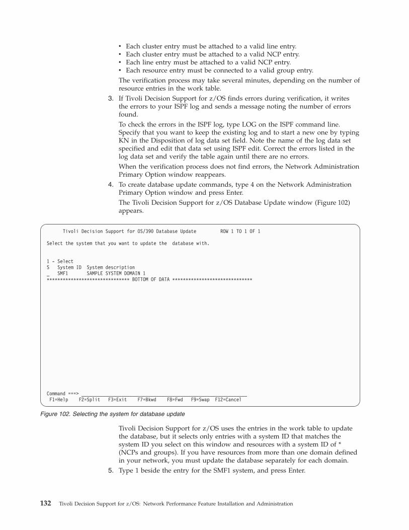
v Each cluster entry must be attached to a valid line entry.
v Each cluster entry must be attached to a valid NCP entry.
v Each line entry must be attached to a valid NCP entry.
v Each resource entry must be connected to a valid group entry.The verification process may take several minutes, depending on the number of
resource entries in the work table.
3. If Tivoli Decision Support for z/OS finds errors during verification, it writes
the errors to your ISPF log and sends a message noting the number of errors
found.
To check the errors in the ISPF log, type LOG on the ISPF command line.
Specify that you want to keep the existing log and to start a new one by typing
KN in the Disposition of log data set field. Note the name of the log data set
specified and edit that data set using ISPF edit. Correct the errors listed in the
log data set and verify the table again until there are no errors.
When the verification process does not find errors, the Network Administration
Primary Option window reappears.
4. To create database update commands, type 4 on the Network Administration
Primary Option window and press Enter.
The Tivoli Decision Support for z/OS Database Update window (Figure 102)
appears.
Tivoli Decision Support for z/OS uses the entries in the work table to update
the database, but it selects only entries with a system ID that matches the
system ID you select on this window and resources with a system ID of *
(NCPs and groups). If you have resources from more than one domain defined
in your network, you must update the database separately for each domain.
5. Type 1 beside the entry for the SMF1 system, and press Enter.
Tivoli Decision Support for OS/390 Database Update ROW 1 TO 1 OF 1
Select the system that you want to update the database with.
1 - Select
S System ID System description
_ SMF1 SAMPLE SYSTEM DOMAIN 1
******************************* BOTTOM OF DATA ******************************
Command ===> ______________________________________________________________
F1=Help F2=Split F3=Exit F7=Bkwd F8=Fwd F9=Swap F12=Cancel
Figure 102. Selecting the system for database update
132 Tivoli Decision Support for z/OS: Network Performance Feature Installation and Administration
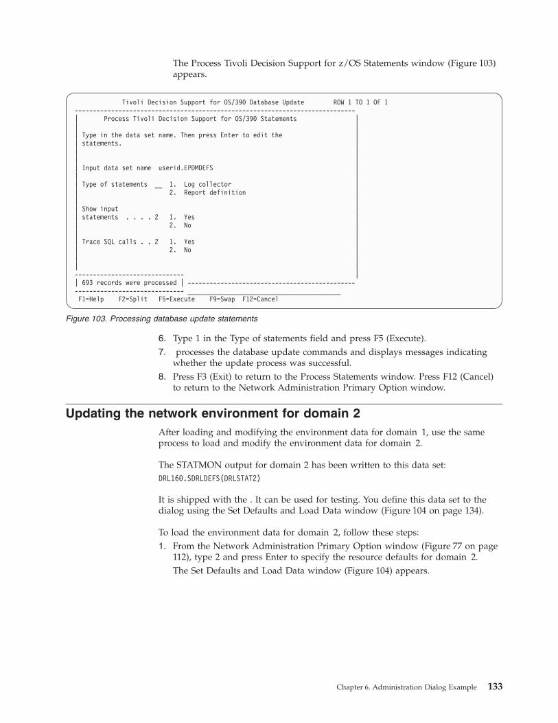
The Process Tivoli Decision Support for z/OS Statements window (Figure 103)
appears.
6. Type 1 in the Type of statements field and press F5 (Execute).
7. processes the database update commands and displays messages indicating
whether the update process was successful.
8. Press F3 (Exit) to return to the Process Statements window. Press F12 (Cancel)
to return to the Network Administration Primary Option window.
Updating the network environment for domain 2
After loading and modifying the environment data for domain 1, use the same
process to load and modify the environment data for domain 2.
The STATMON output for domain 2 has been written to this data set:
DRL160.SDRLDEFS(DRLSTAT2)
It is shipped with the . It can be used for testing. You define this data set to the
dialog using the Set Defaults and Load Data window (Figure 104 on page 134).
To load the environment data for domain 2, follow these steps:
1. From the Network Administration Primary Option window (Figure 77 on page
112), type 2 and press Enter to specify the resource defaults for domain 2.
The Set Defaults and Load Data window (Figure 104) appears.
Tivoli Decision Support for OS/390 Database Update ROW 1 TO 1 OF 1
-----------------------------------------------------------------------------
| Process Tivoli Decision Support for OS/390 Statements |
| |
| Type in the data set name. Then press Enter to edit the |
| statements. |
| |
| |
| Input data set name userid.EPDMDEFS |
| |
| Type of statements __ 1. Log collector |
| 2. Report definition |
| |
| Show input |
| statements . . . . 2 1. Yes |
| 2. No |
| |
| Trace SQL calls . . 2 1. Yes |
| 2. No |
| |
| |
------------------------------ |
| 693 records were processed | ----------------------------------------------
------------------------------ __________________________________________
F1=Help F2=Split F5=Execute F9=Swap F12=Cancel
Figure 103. Processing database update statements
Chapter 6. Administration Dialog Example 133
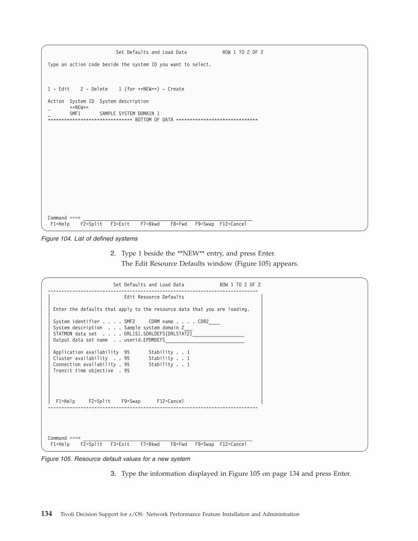
2. Type 1 beside the **NEW** entry, and press Enter.
The Edit Resource Defaults window (Figure 105) appears.
3. Type the information displayed in Figure 105 on page 134 and press Enter.
Set Defaults and Load Data ROW 1 TO 2 OF 2
Type an action code beside the system ID you want to select.
1 - Edit 2 - Delete 1 (for **NEW**) - Create
Action System ID System description
_ **NEW**
_ SMF1 SAMPLE SYSTEM DOMAIN 1
******************************* BOTTOM OF DATA ******************************
Command ===> ______________________________________________________________
F1=Help F2=Split F3=Exit F7=Bkwd F8=Fwd F9=Swap F12=Cancel
Figure 104. List of defined systems
Set Defaults and Load Data ROW 1 TO 2 OF 2
-----------------------------------------------------------------------------
| Edit Resource Defaults |
| |
| Enter the defaults that apply to the resource data that you are loading. |
| |
| System identifier . . . . SMF2 CDRM name . . . . CDR2____ |
| System description . . . Sample system domain 2___ |
| STATMON data set . . . . DRL151.SDRLDEFS(DRLSTAT2)___________________ |
| Output data set name . . userid.EPDMDEFS_____________________________ |
| |
| Application availability 95 Stability . . 1 |
| Cluster availability . . 95 Stability . . 1 |
| Connection availability . 95 Stability . . 1 |
| Transit time objective . 95 |
| |
| |
| |
| |
| F1=Help F2=Split F9=Swap F12=Cancel |
-----------------------------------------------------------------------------
Command ===> ______________________________________________________________
F1=Help F2=Split F3=Exit F7=Bkwd F8=Fwd F9=Swap F12=Cancel
Figure 105. Resource default values for a new system
134 Tivoli Decision Support for z/OS: Network Performance Feature Installation and Administration
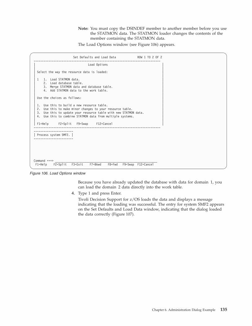
Note: You must copy the DSINDEF member to another member before you use
the STATMON data. The STATMON loader changes the contents of the
member containing the STATMON data.
The Load Options window (see Figure 106) appears.
Because you have already updated the database with data for domain 1, you
can load the domain 2 data directly into the work table.
4. Type 1 and press Enter.
Tivoli Decision Support for z/OS loads the data and displays a message
indicating that the loading was successful. The entry for system SMF2 appears
on the Set Defaults and Load Data window, indicating that the dialog loaded
the data correctly (Figure 107).
Set Defaults and Load Data ROW 1 TO 2 OF 2
-----------------------------------------------------------------------------
| Load Options |
| |
| Select the way the resource data is loaded: |
| |
| 1 1. Load STATMON data. |
| 2. Load database table. |
| 3. Merge STATMON data and database table. |
| 4. Add STATMON data to the work table. |
| |
| Use the choices as follows: |
| |
| 1. Use this to build a new resource table. |
| 2. Use this to make minor changes to your resource table. |
| 3. Use this to update your resource table with new STATMON data. |
| 4. Use this to combine STATMON data from multiple systems. |
| |
| F1=Help F2=Split F9=Swap F12=Cancel |
-----------------------------------------------------------------------------
------------------------
| Process system SMF2. |
------------------------
Command ===> ______________________________________________________________
F1=Help F2=Split F3=Exit F7=Bkwd F8=Fwd F9=Swap F12=Cancel
Figure 106. Load Options window
Chapter 6. Administration Dialog Example 135
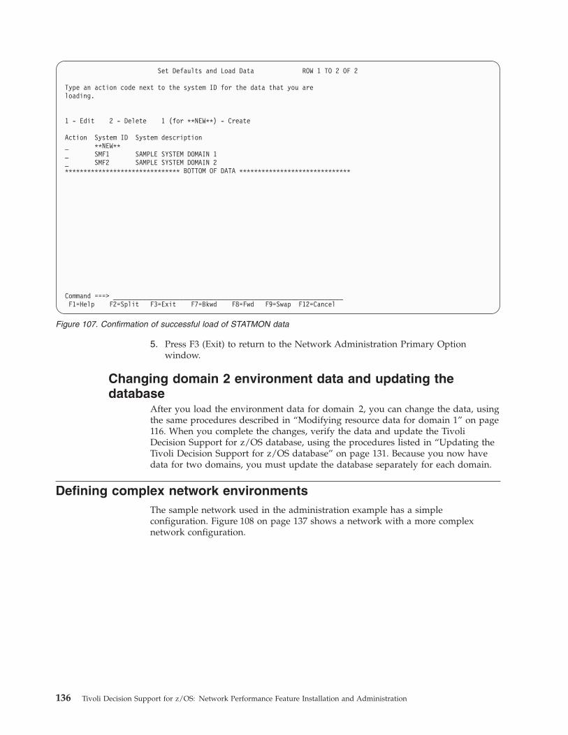
5. Press F3 (Exit) to return to the Network Administration Primary Option
window.
Changing domain 2 environment data and updating the
database
After you load the environment data for domain 2, you can change the data, using
the same procedures described in “Modifying resource data for domain 1” on page
116. When you complete the changes, verify the data and update the Tivoli
Decision Support for z/OS database, using the procedures listed in “Updating the
Tivoli Decision Support for z/OS database” on page 131. Because you now have
data for two domains, you must update the database separately for each domain.
Defining complex network environments
The sample network used in the administration example has a simple
configuration. Figure 108 on page 137 shows a network with a more complex
network configuration.
Set Defaults and Load Data ROW 1 TO 2 OF 2
Type an action code next to the system ID for the data that you are
loading.
1 - Edit 2 - Delete 1 (for **NEW**) - Create
Action System ID System description
_ **NEW**
_ SMF1 SAMPLE SYSTEM DOMAIN 1
_ SMF2 SAMPLE SYSTEM DOMAIN 2
******************************* BOTTOM OF DATA ******************************
Command ===> ______________________________________________________________
F1=Help F2=Split F3=Exit F7=Bkwd F8=Fwd F9=Swap F12=Cancel
Figure 107. Confirmation of successful load of STATMON data
136 Tivoli Decision Support for z/OS: Network Performance Feature Installation and Administration
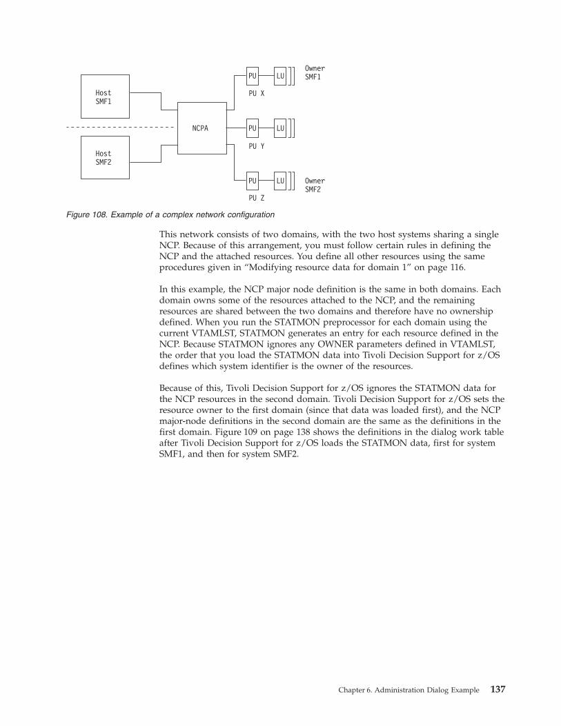
This network consists of two domains, with the two host systems sharing a single
NCP. Because of this arrangement, you must follow certain rules in defining the
NCP and the attached resources. You define all other resources using the same
procedures given in “Modifying resource data for domain 1” on page 116.
In this example, the NCP major node definition is the same in both domains. Each
domain owns some of the resources attached to the NCP, and the remaining
resources are shared between the two domains and therefore have no ownership
defined. When you run the STATMON preprocessor for each domain using the
current VTAMLST, STATMON generates an entry for each resource defined in the
NCP. Because STATMON ignores any OWNER parameters defined in VTAMLST,
the order that you load the STATMON data into Tivoli Decision Support for z/OS
defines which system identifier is the owner of the resources.
Because of this, Tivoli Decision Support for z/OS ignores the STATMON data for
the NCP resources in the second domain. Tivoli Decision Support for z/OS sets the
resource owner to the first domain (since that data was loaded first), and the NCP
major-node definitions in the second domain are the same as the definitions in the
first domain. Figure 109 on page 138 shows the definitions in the dialog work table
after Tivoli Decision Support for z/OS loads the STATMON data, first for system
SMF1, and then for system SMF2.
NCPA
HostSMF1
HostSMF2
PU
PU
PU
PU X
PU Y
PU Z
OwnerSMF1
OwnerSMF2
LU
LU
LU
Figure 108. Example of a complex network configuration
Chapter 6. Administration Dialog Example 137
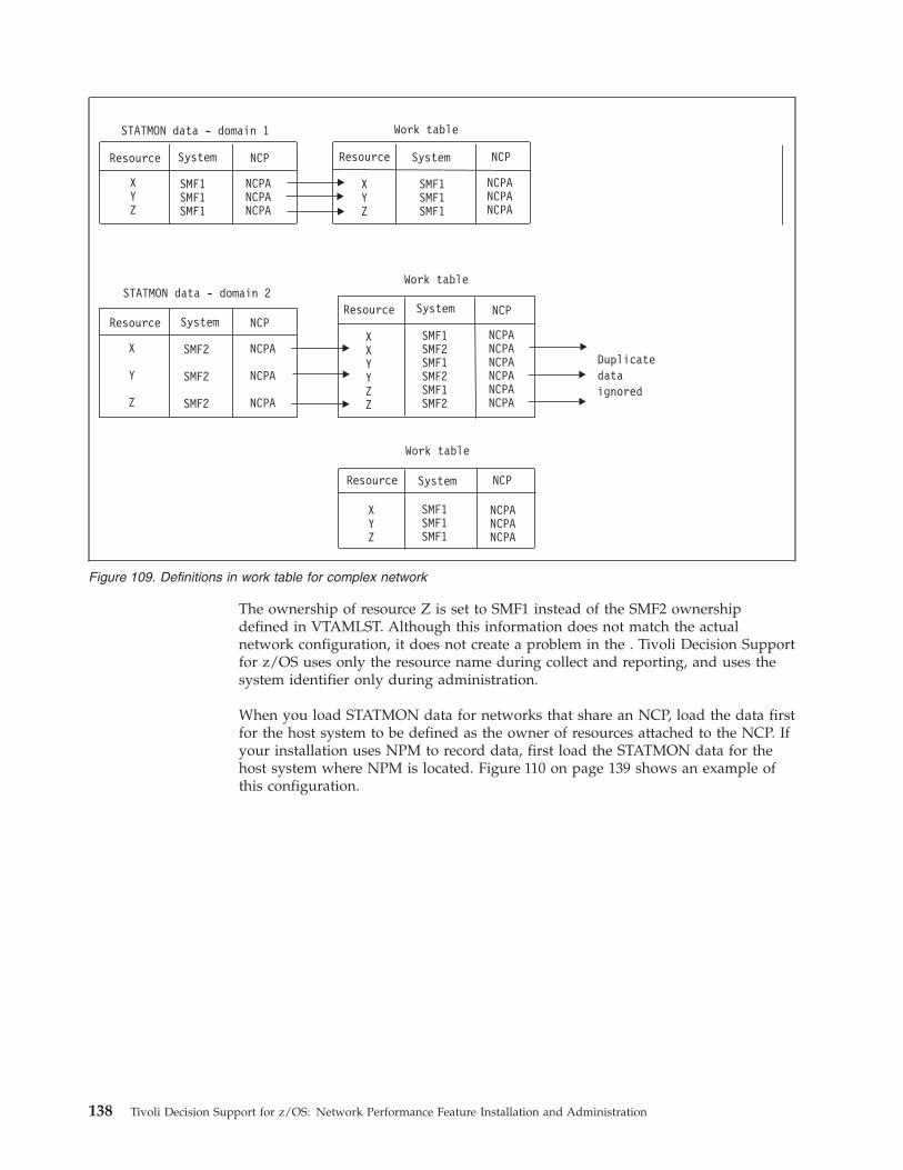
The ownership of resource Z is set to SMF1 instead of the SMF2 ownership
defined in VTAMLST. Although this information does not match the actual
network configuration, it does not create a problem in the . Tivoli Decision Support
for z/OS uses only the resource name during collect and reporting, and uses the
system identifier only during administration.
When you load STATMON data for networks that share an NCP, load the data first
for the host system to be defined as the owner of resources attached to the NCP. If
your installation uses NPM to record data, first load the STATMON data for the
host system where NPM is located. Figure 110 on page 139 shows an example of
this configuration.
Figure 109. Definitions in work table for complex network
138 Tivoli Decision Support for z/OS: Network Performance Feature Installation and Administration
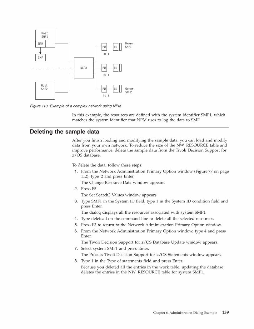
In this example, the resources are defined with the system identifier SMF1, which
matches the system identifier that NPM uses to log the data to SMF.
Deleting the sample data
After you finish loading and modifying the sample data, you can load and modify
data from your own network. To reduce the size of the NW_RESOURCE table and
improve performance, delete the sample data from the Tivoli Decision Support for
z/OS database.
To delete the data, follow these steps:
1. From the Network Administration Primary Option window (Figure 77 on page
112), type 2 and press Enter.
The Change Resource Data window appears.
2. Press F5.
The Set Search2 Values window appears.
3. Type SMF1 in the System ID field, type 1 in the System ID condition field and
press Enter.
The dialog displays all the resources associated with system SMF1.
4. Type deleteall on the command line to delete all the selected resources.
5. Press F3 to return to the Network Administration Primary Option window.
6. From the Network Administration Primary Option window, type 4 and press
Enter.
The Tivoli Decision Support for z/OS Database Update window appears.
7. Select system SMF1 and press Enter.
The Process Tivoli Decision Support for z/OS Statements window appears.
8. Type 1 in the Type of statements field and press Enter.
Because you deleted all the entries in the work table, updating the database
deletes the entries in the NW_RESOURCE table for system SMF1.
Figure 110. Example of a complex network using NPM
Chapter 6. Administration Dialog Example 139
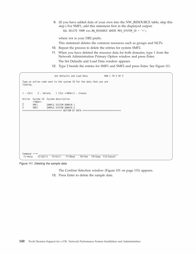
9. (If you have added data of your own into the NW_RESOURCE table, skip this
step.) For SMF1, add this statement first in the displayed output:
SQL DELETE FROM xxx.NW_RESOURCE WHERE MVS_SYSTEM_ID = ’*’;
where xxx is your DB2 prefix.
This statement deletes the common resources such as groups and NCPs.
10. Repeat the process to delete the entries for system SMF2.
11. When you have deleted the resource data for both domains, type 1 from the
Network Administration Primary Option window and press Enter.
The Set Defaults and Load Data window appears.
12. Type 2 beside the entries for SMF1 and SMF2 and press Enter. See Figure 111.
The Confirm Selection window (Figure 101 on page 131) appears.
13. Press Enter to delete the sample data.
Set Defaults and Load Data ROW 1 TO 2 OF 2
Type an action code next to the system ID for the data that you are
loading.
1 - Edit 2 - Delete 1 (for **NEW**) - Create
Action System ID System description
_ **NEW**
2 SMF1 SAMPLE SYSTEM DOMAIN 1
2 SMF2 SAMPLE SYSTEM DOMAIN 2
******************************* BOTTOM OF DATA ******************************
Command ===> ______________________________________________________________
F1=Help F2=Split F3=Exit F7=Bkwd F8=Fwd F9=Swap F12=Cancel
Figure 111. Deleting the sample data
140 Tivoli Decision Support for z/OS: Network Performance Feature Installation and Administration
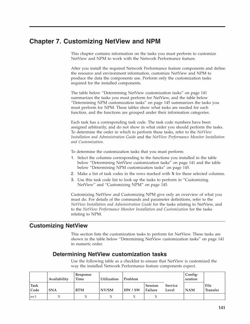
Chapter 7. Customizing NetView and NPM
This chapter contains information on the tasks you must perform to customize
NetView and NPM to work with the Network Performance feature.
After you install the required Network Performance feature components and define
the resource and environment information, customize NetView and NPM to
produce the data the components use. Perform only the customization tasks
required for the installed components.
The table below “Determining NetView customization tasks” on page 141
summarizes the tasks you must perform for NetView, and the table below
“Determining NPM customization tasks” on page 145 summarizes the tasks you
must perform for NPM. These tables show what tasks are needed for each
function, and the functions are grouped under their information categories.
Each task has a corresponding task code. The task code numbers have been
assigned arbitrarily, and do not show in what order you should perform the tasks.
To determine the order in which to perform these tasks, refer to the NetView
Installation and Administration Guide and the NetView Performance Monitor Installation
and Customization.
To determine the customization tasks that you must perform:
1. Select the columns corresponding to the functions you installed in the table
below “Determining NetView customization tasks” on page 141 and the table
below “Determining NPM customization tasks” on page 145.
2. Make a list of task codes in the rows marked with X for these selected columns.
3. Use this task code list to look up the tasks to perform in “Customizing
NetView” and “Customizing NPM” on page 145.
Customizing NetView and Customizing NPM give only an overview of what you
must do. For details of the commands and parameter definitions, refer to the
NetView Installation and Administration Guide for the tasks relating to NetView, and
to the NetView Performance Monitor Installation and Customization for the tasks
relating to NPM.
Customizing NetView
This section lists the customization tasks to perform for NetView. These tasks are
shown in the table below “Determining NetView customization tasks” on page 141
in numeric order.
Determining NetView customization tasks
Use the following table as a checklist to ensure that NetView is customized the
way the installed Network Performance feature components expect.
Availability
Response
Time Utilization Problem
Service
Level
Config-
uration
File
Transfer
Task
Code SNA RTM NV/SM HW / SW
Session
Failure NAM
nv1 X X X X X
141
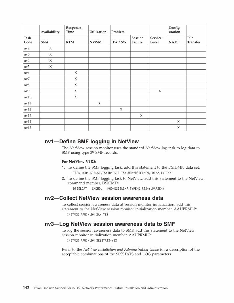
Availability
Response
Time Utilization Problem
Service
Level
Config-
uration
File
Transfer
Task
Code SNA RTM NV/SM HW / SW
Session
Failure NAM
nv2 X
nv3 X
nv4 X
nv5 X
nv6 X
nv7 X
nv8 X
nv9 X X
nv10 X
nv11 X
nv12 X
nv13 X
nv14 X
nv15 X
nv1—Define SMF logging in NetView
The NetView session monitor uses the standard NetView log task to log data to
SMF using type 39 SMF records.
For NetView V1R3:
1. To define the SMF logging task, add this statement to the DSIDMN data set:
TASK MOD=DSIZDST,TSKID=DSIELTSK,MEM=DSIELMEM,PRI=2,INIT=Y
2. To define the SMF logging task to NetView, add this statement to the NetView
command member, DSICMD:
DSIELDAT CMDMDL MOD=DSIELSMF,TYPE=D,RES=Y,PARSE=N
nv2—Collect NetView session awareness data
To collect session awareness data at session monitor initialization, add this
statement to the NetView session monitor initialization member, AAUPRMLP:
INITMOD AAUINLDM SAW=YES
nv3—Log NetView session awareness data to SMF
To log the session awareness data to SMF, add this statement to the NetView
session monitor initialization member, AAUPRMLP:
INITMOD AAUINLDM SESSTATS=YES
Refer to the NetView Installation and Administration Guide for a description of the
acceptable combinations of the SESSTATS and LOG parameters.
142 Tivoli Decision Support for z/OS: Network Performance Feature Installation and Administration
nv4—Reduce the CPU and storage utilization in the session
monitor
To reduce the CPU and storage utilization in the session monitor, collect session
awareness data only for the sessions in which you are interested. To specify the
sessions for which you want session awareness data collected, filter the collection
of session awareness data in VTAM rather than NetView.
nv5—Collect session statistics for active sessions
To record session statistics for all sessions to be included in the availability process,
issue this command:
NLDM RECORD SESSTATS resource1 resource2
Resource1 is the name of the SSCP in the VTAM host where NetView is running.
Resource2 can be any of these resources:
SSCP in another host Use this value to measure cross-connection
availability.
PU Use this value to measure cluster and NCP
availability.
Application LUs Use this value to measure application availability.
Issue this command at regular time intervals. You can use NetView CLISTs to issue
commands automatically. The recommended interval is 30 minutes.
nv6—Collect RTM data in NetView session monitor
To collect RTM data in NetView at session monitor initialization, add the
parameter RTM=YES to the AAUINLDM statement in the NetView session monitor
initialization member, AAUPRMLP. For example:
INITMOD AAUINLDM RTM=YES
nv7—Log NetView session monitor RTM data to SMF
To log the NetView session monitor RTM data to SMF, add the parameter
LOG=YES to the AAUINLDM statement in the NetView session monitor
initialization member, AAUPRMLP. For example:
INITMOD AAUINLDM LOG=YES
nv8—Collect RTM data and log to SMF
To collect and log the RTM data to SMF, issue this command:
NLDM COLLECT RTM * LOG
Issue this command at regular time intervals. You can use NetView CLISTs to issue
commands automatically. The recommended interval is 30 minutes.
nv9—Define RTM performance classes
The RTM objectives are defined in the performance classes. The Network
Performance feature also uses the objectives as the service-level agreements in the
Network Performance feature service reports. Define these performance classes for
each application:
v One class for local terminals
v One class for terminals attached to a local NCP
v One class for terminals attached to a remote NCP
Chapter 7. Customizing NetView and NPM 143
Use PCLASS to define the performance class definitions. Use MAPSESS to map LU
names to performance classes. Refer to the NetView Installation and Administration
Guide for more information on defining performance classes.
nv10—Customize cluster controllers for RTM
Customize the controllers to produce the RTM data. For details on this procedure,
refer to the manual for IBM controllers 3274, 3174, and 3708.
nv11—Collect session monitor utilization data
To collect the session monitor utilization data, issue this command:
NLDM RECORD STRGDATA
This command tells NetView to log information on the amount of storage used by
the session monitor. Issue this command at regular intervals. You can use NetView
CLISTs to issue commands automatically. The recommended interval is 30 minutes.
nv12—Start and stop hardware monitor logging
To start logging hardware monitor data to SMF, issue this command:
REPORTS ON
To stop logging hardware monitor data to SMF, issue this command:
REPORTS OFF
You can issue the REPORTS ON command automatically by adding it to member
BNJAPAMA, or use NetView CLISTs to issue both commands. For example, to
collect the hardware monitor data only during service hours, add these commands
to a NetView CLIST:
AT 7:00 PPT,NPDA REPORTS ON
AT 18:00 PPT,NPDA REPORTS OFF
nv13—Collect session failure data in NetView session monitor
To collect the session failure data, add the parameter LOG=YES to the AAUINLDM
statement in the NetView session monitor initialization member, AAUPRMLP. For
example:
INITMOD AAUINLDM LOG=YES
nv14—Activate the network asset management function
Refer to the NetView Installation and Administration Guide for detailed information
on activating the network asset management function.
nv15—Collect configuration data
Issue VPD commands for the devices for which you want to collect configuration
data. You can use NetView CLISTs to issue these commands automatically. Refer to
the NetView Installation and Administration Guide for more information on defining
these commands.
144 Tivoli Decision Support for z/OS: Network Performance Feature Installation and Administration
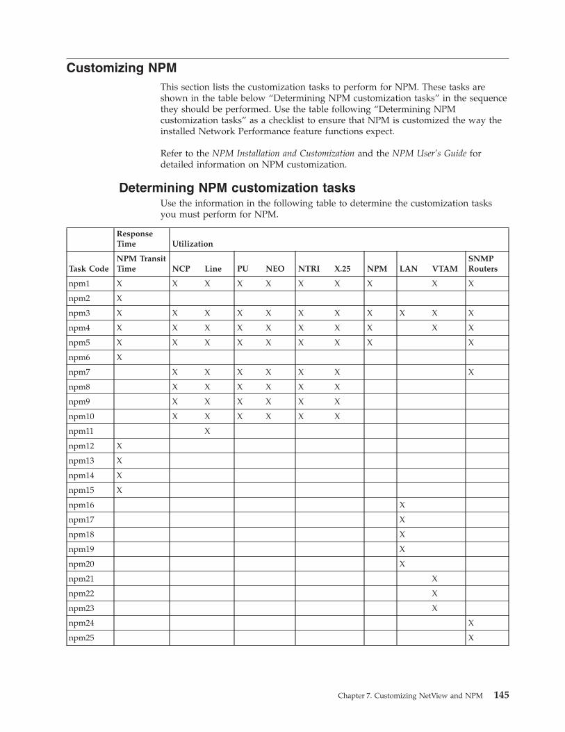
Customizing NPM
This section lists the customization tasks to perform for NPM. These tasks are
shown in the table below “Determining NPM customization tasks” in the sequence
they should be performed. Use the table following “Determining NPM
customization tasks” as a checklist to ensure that NPM is customized the way the
installed Network Performance feature functions expect.
Refer to the NPM Installation and Customization and the NPM User’s Guide for
detailed information on NPM customization.
Determining NPM customization tasks
Use the information in the following table to determine the customization tasks
you must perform for NPM.
Response
Time Utilization
Task Code
NPM Transit
Time NCP Line PU NEO NTRI X.25 NPM LAN VTAM
SNMP
Routers
npm1 X X X X X X X X X X
npm2 X
npm3 X X X X X X X X X X X
npm4 X X X X X X X X X X
npm5 X X X X X X X X X
npm6 X
npm7 X X X X X X X
npm8 X X X X X X
npm9 X X X X X X
npm10 X X X X X X
npm11 X
npm12 X
npm13 X
npm14 X
npm15 X
npm16 X
npm17 X
npm18 X
npm19 X
npm20 X
npm21 X
npm22 X
npm23 X
npm24 X
npm25 X
Chapter 7. Customizing NetView and NPM 145
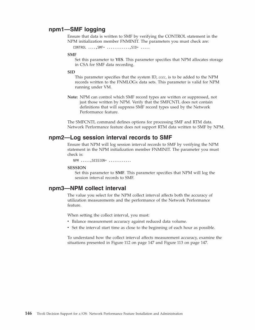
npm1—SMF logging
Ensure that data is written to SMF by verifying the CONTROL statement in the
NPM initialization member FNMINIT. The parameters you must check are:
CONTROL ....,SMF= ............,SID= .....
SMF
Set this parameter to YES. This parameter specifies that NPM allocates storage
in CSA for SMF data recording.
SID
This parameter specifies that the system ID, cccc, is to be added to the NPM
records written to the FNMLOGx data sets. This parameter is valid for NPM
running under VM.
Note: NPM can control which SMF record types are written or suppressed, not
just those written by NPM. Verify that the SMFCNTL does not contain
definitions that will suppress SMF record types used by the Network
Performance feature.
The SMFCNTL command defines options for processing SMF and RTM data.
Network Performance feature does not support RTM data written to SMF by NPM.
npm2—Log session interval records to SMF
Ensure that NPM will log session interval records to SMF by verifying the NPM
statement in the NPM initialization member FNMINIT. The parameter you must
check is:
NPM .....,SESSION= ............
SESSION
Set this parameter to SMF. This parameter specifies that NPM will log the
session interval records to SMF.
npm3—NPM collect interval
The value you select for the NPM collect interval affects both the accuracy of
utilization measurements and the performance of the Network Performance
feature.
When setting the collect interval, you must:
v Balance measurement accuracy against reduced data volume.
v Set the interval start time as close to the beginning of each hour as possible.
To understand how the collect interval affects measurement accuracy, examine the
situations presented in Figure 112 on page 147 and Figure 113 on page 147.
146 Tivoli Decision Support for z/OS: Network Performance Feature Installation and Administration
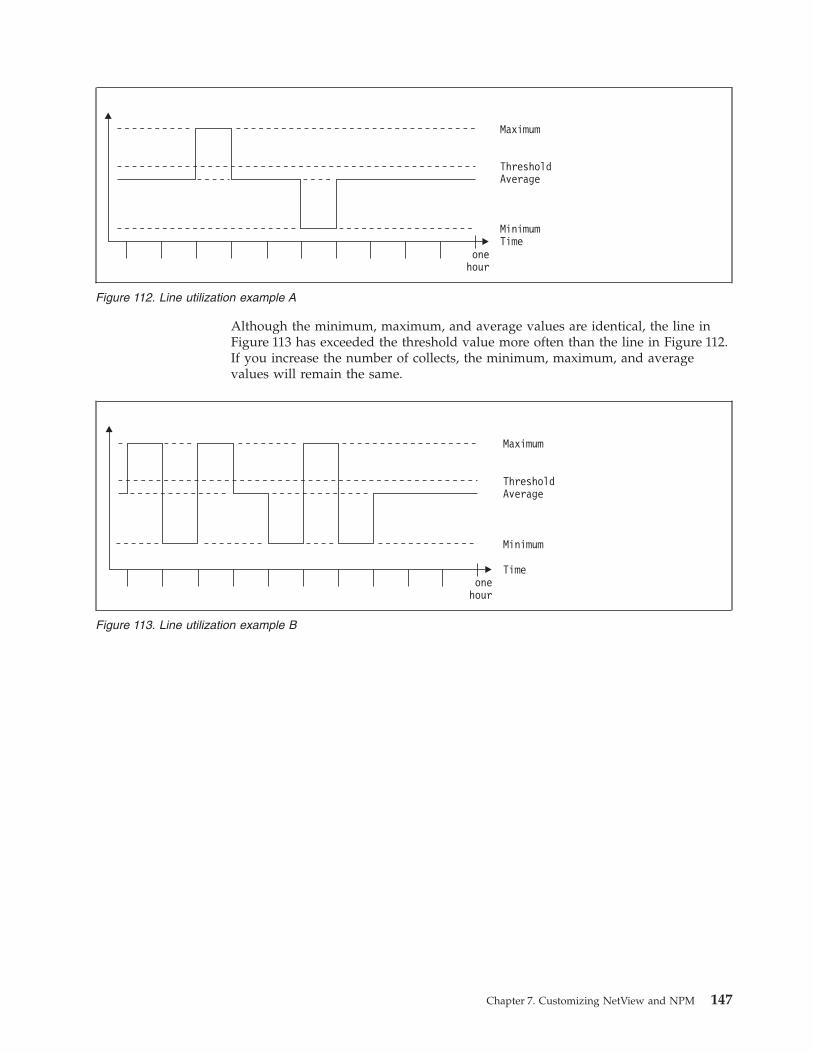
Although the minimum, maximum, and average values are identical, the line in
Figure 113 has exceeded the threshold value more often than the line in Figure 112.
If you increase the number of collects, the minimum, maximum, and average
values will remain the same.
Maximum
ThresholdAverage
MinimumTime
onehour
Figure 112. Line utilization example A
Maximum
ThresholdAverage
Time
Minimum
onehour
Figure 113. Line utilization example B
Chapter 7. Customizing NetView and NPM 147

To provide a clearer picture of utilization, the Network Performance feature uses
two methods to measure utilization:
v Using a series of counters, each representing 10 percent utilization, that are
incremented during each interval. For example, if the feature measures 30
percent utilization, the 10%, 20%, and 30% counters are each incremented by
one.
v Measuring the percentage of intervals the utilization is above the threshold
value.
If you set the collect interval to once an hour and measure the percentage of
intervals above the threshold for Figure 112 on page 147 and Figure 113 on page
147, the log record indicates that utilization exceeded the threshold during the
interval in both examples. Because there is only one interval, the value for
percentage of intervals above the threshold is 100% in both examples.
If you set the collect interval to ten times an hour, the line in Figure 112 on page
147 has one interval during which utilization exceeded the threshold, so the value
is 10%. The line in Figure 113 on page 147 has three intervals during which
utilization exceeded the threshold, so the value is 30%.
Although the shorter collect interval produces more accurate utilization
measurements, the accuracy comes at the cost of having to write many more SMF
records. When deciding on the collect interval to use, you must balance these
factors.
Define the interval in “npm4—Define the base interval” on page 149.
When you have selected the collect interval, you must decide when each interval
starts. The interval starting time also affects measurement accuracy.
In the example in Figure 114 on page 149, the collect intervals for Collect A and
Collect B are both set to one hour, but the interval starting times are different.
In both cases, the interval t1 to t2 represents data for 11:00 to 12:00. However, most
of that interval in Collect A actually takes place during the time from 12:00 to
13:00, while the interval in Collect B closely matches the 11:00 to 12:00 period. If a
problem occurs at 12:15, Collect A stores the event as part of the t1 to t2 data,
indicating that the event happened between 11:00 and 12:00. Collect B stores the
event as part of the t2 to t3 data, indicating that the event happened between 12:00
and 13:00, which is correct.
Define the interval synchronization in “npm5—Define the interval
synchronization” on page 149.
148 Tivoli Decision Support for z/OS: Network Performance Feature Installation and Administration
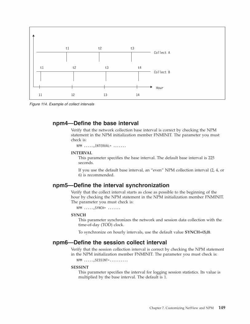
npm4—Define the base interval
Verify that the network collection base interval is correct by checking the NPM
statement in the NPM initialization member FNMINIT. The parameter you must
check is:
NPM .....,INTERVAL= .......
INTERVAL
This parameter specifies the base interval. The default base interval is 225
seconds.
If you use the default base interval, an “even” NPM collection interval (2, 4, or
6) is recommended.
npm5—Define the interval synchronization
Verify that the collect interval starts as close as possible to the beginning of the
hour by checking the NPM statement in the NPM initialization member FNMINIT.
The parameter you must check is:
NPM .....,SYNCH= .......
SYNCH
This parameter synchronizes the network and session data collection with the
time-of-day (TOD) clock.
To synchronize on hourly intervals, use the default value SYNCH=(5,0).
npm6—Define the session collect interval
Verify that the session collection interval is correct by checking the NPM statement
in the NPM initialization member FNMINIT. The parameter you must check is:
NPM .....,SESSINT=..........
SESSINT
This parameter specifies the interval for logging session statistics. Its value is
multiplied by the base interval. The default is 1.
Collect At1
t1
t2
t2
t3
t3 t4
11 12 13 14
Collect B
Hour
Figure 114. Example of collect intervals
Chapter 7. Customizing NetView and NPM 149

npm7—Collect network data
Ensure that you have completed all the steps necessary to install the NPM network
data collection functions. Refer to the NPM Installation and Customization for
detailed information.
npm8—Define NCP to NPM
Verify that NPM has information about the network configuration (NCPs and their
resources) by checking the NCP statement in the NPM initialization member
FNMINIT (releases prior to NPM 1.5), or FNMSCMDS or FNMSTRT (NPM 1.5 and
later releases). The parameter you must check is:
NCP ....PUNAME=,..........
PUNAME
This parameter assigns a unique name to the CCU. The name assigned on this
parameter can change the way the Network Performance feature translates
NCP synonyms. For the Network Performance feature, you should either not
specify this parameter or set the PU name to be the same as the NCP synonym
name.
npm9—Collect network data
Ensure that network data is collected for resources supported by the installed
Network Performance feature functions by adding either the
v START COLLECT commands (when NPM version 1)
or
v NETCOLL commands (when NPM version 2)
to the NPM commands member FNMSTRT for those network resources whose
data you want to collect.
Refer to the NPM Installation and Customization for detailed information.
The START COLLECT command
In NPM 1.5 and later releases, the START COLLECT commands are not required to
be in FNMSTRT. The parameters you must check are:
START COLLECT ,interval number,...,LOG=.....,CLOCK=.....,DAILY=.....
interval number
This parameter specifies which of the eight collection intervals to use. You can
use different intervals for different resources. If you use the default base
interval value, an even interval (2, 4, or 6) is recommended.
LOG
You must set this parameter to SMF to specify that NPM will log the network
data records to SMF.
CLOCK and DAILY
Set these parameters to match the time and frequency of the collection period.
150 Tivoli Decision Support for z/OS: Network Performance Feature Installation and Administration
The NETCOLL command
The parameters you must check are:
NETCOLL ,INTERVAL=,...,DEST=.....,CLOCK=.....,DAILY=.....
INTERVAL
This parameter specifies which of the collection intervals (1 to 7) to use. You
can use different intervals for different resources. If you use the default base
interval value, an even interval (2, 4, or 6) is recommended.
DEST
You must set this parameter to SMF to specify that NPM will log the network
data records to SMF.
CLOCK and DAILY
Set these parameters to match the time and frequency of the collection period.
npm10—Enable network collection
Verify that NPM can collect data from resources supported by the Network
Performance feature components by verifying that the resource definitions contain
NPACOLL=YES. If the resource is an X.25 or a NEO resource, the resource
definitions should contain NPACOLL=(YES,EXTENDED).
Note: This release of Network Performance feature does not support Frame Relay,
Ethernet, and ODLC resources
Specify this parameter in the NCPs and verify that the setting in the GENERIC
command does not overwrite the value specified in the NCP.
Verify that NPA=YES or NPA=(YES,DR) is defined on the NCP BUILD statement.
npm11—Verify line speed
The line utilization, X.25 utilization, and NEO utilization components all depend
on the correct line speed definition. Define the line speed in one of the following
sources:
v SPEED on the LINE macro in the NCP source
v NPM.SPEED on the LINE macro in the NCP source
v SPEED on the GENERIC statement in an NPM Exec
v SPEED on the LINE statement in an NPM Exec
npm12—Collect transit time
Ensure that you have completed all the steps necessary to install the NPM session
data collection function. If NPM has to support NetView Access Services (NVAS)
or TPX** (in NPM 2.2), the install steps for collecting session data for Session
Managers must be performed.
Define the session collection function to measure the NPM transit time by
application. For each application in which you want to measure the transit time,
define a SESSCOLL command.
Collecting transit-time data by application rather than by NCP saves common
storage area (CSA). You need not define SESSCOLL=YES in the NCP statement for
the Network Performance feature to collect transit-time data.
Refer to the NPM Installation and Customization for detailed information.
Chapter 7. Customizing NetView and NPM 151
npm13—Define NPM APPL statements
To specify the applications for which you want NPM to perform session data
collection, define an APPL statement in the NPM initialization member, FNMINIT.
The APPL statement defines application characteristics for data collection. The
parameters you must check are:
APPL MAXL=...,RSP=...,TYPE=...,SYNCOUNT=...,SYNMASK=...
SYN, SYNCOUNT, and SYNMASK
If you define a synonym name for the application, you must match this name
with the synonym name defined in the Network Performance feature
administration dialog.
MAXL
The maximum number of LUs.
RSP
This parameter controls whether the application uses dynamic definite
response (DDR). RSP=YES enables the application for DDR.
TYPE
This parameter specifies if the application is IMS or NVAS.
Refer to the NPM Installation and Customization for more information about the
APPL statement.
npm14—Define transit-time objective
The SESSCOLL command defines the objective for NPM transit time. Use the
SESSCOLL command to define:
v Transit-time objectives for the categories operator (OPER), host (HOST), and
network (NET). The Network Performance feature uses the high threshold value
for the OPER, HOST, and NET parameters as the service-level objective.
v Boundary values (BVAL). The BVAL parameter sets the boundary values used in
measuring transit time.
The THRESHOLD statement in the NPM initialization member, FNMINIT, defines
the default values.
npm15—Collect session data for each resource
To define the time to start and stop data collection for each application monitored
by NPM, add a SESSCOLL command to the NPM commands member, FNMSTRT.
You can also issue the SESSCOLL command from the console with NPM 1.6 and
later releases. The parameters you must check are:
SESSCOLL RESOURCE=..,BVAL=..,DAILY=..,CLOCK=..,HOST=..,NETWORK=..,OPERATOR=...
RESOURCE
This parameter should be set to the name of the actual application.
BVAL
This parameter defines the boundary values that depend on the operator
objective (high threshold). You should set boundary value 2 or 3 equal to the
operator objective to track how the transit time compares to the objective.
CLOCK and DAILY
Set these parameters to match the time and frequency of the collection period.
HOST
This parameter defines the high threshold value, which you should set equal to
152 Tivoli Decision Support for z/OS: Network Performance Feature Installation and Administration
the host transit-time objective. The Network Performance feature uses the
value of this parameter as the objective when processing transit-time data.
NETWORK
This parameter defines the high threshold value, which you should set equal to
the network transit-time objective. The Network Performance feature uses the
value of this parameter as the objective when processing transit-time data.
OPERATOR
This parameter defines the high threshold value, which you should set equal to
the operator transit-time objective. The Network Performance feature uses the
value of this parameter as the objective when processing transit-time data.
npm16—Enable LAN data collection
Ensure that NPM, NetView, and the LAN Manager(s) are set up correctly to collect
the LAN bridge and/or segment data. Verify the NPM statement in the NPM
initialization member FNMINIT. The parameters you must check are:
NPM ....,LAN=....,LANCOLL=....
LAN
Set this parameter to SMF. This parameter specifies that NPM will log the LAN
interval records to SMF.
LANCOLL
Set this parameter to YES. This parameter specifies that LAN data will be
collected by NPM.
Refer to NPM Installation and Customization for detailed information.
npm17—Define LAN Managers
Each LAN manager that NPM will collect data from must be defined. Verify that a
LANMGR command is defined in FNMSCMDS or FNMSTRT for each LAN
Manager in your network. The parameters you must check are:
LANMGR ADDRESS=....,SP=....,OPTION=....
ADDRESS
This parameter specifies the adapter address used by the LAN Manager.
SP™
This parameter specifies the PU name of the LAN Manager service point as
defined to VTAM.
OPTION
Set this parameter to ADD and it will add this LAN Manager to NPM.
npm18—Define the LAN collection interval
Verify that the bridge and segment collection intervals are correct by checking the
NPM statement in the NPM initialization member FNMINIT. The parameters you
must check are:
NPM ....,LBRGINT=....,LSEGINT=....
LBRGINT
This parameter specifies the interval and interval synchronization for collecting
LAN bridge data. The default is (15,0).
LSEGINT
This parameter specifies the interval and interval synchronization for collecting
LAN segment data. The default is (15,0,40).
Chapter 7. Customizing NetView and NPM 153

Refer to “Using the INTERVAL parameter” in the NPM Installation and
Customization.
154 Tivoli Decision Support for z/OS: Network Performance Feature Installation and Administration
npm19—Collect LAN bridge data
For each LAN bridge you want to collect data from, code an LBRGCOLL
command in FNMSTRT or start LAN data collection using NPM online panels, an
NPM EXEC, or NPM console support. The parameters you must check are:
LBRGCOLL BRIDGE=....,BC=....,NB=....,LF=....,CLOCK=....,DAILY=....
BRIDGE
This parameter specifies the name of the bridge.
BC
If you want to include threshold for broadcast frames forwarded in the
reporting, set the high threshold parameter for segment 1 and segment 2 equal
to the threshold value.
NB
If you want to include threshold for nonbroadcast frames forwarded in the
reporting, set the high threshold parameter for segment 1 and segment 2 equal
to the threshold value.
LF If you want to include threshold for lost frames in the reporting, set the high
threshold parameter for segment 1 and segment 2 equal to the threshold value.
CLOCK and DAILY
Set these parameters to match the time and frequency of the collection period.
npm20—Collect LAN segment data
For each LAN segment you want to collect data from, code an LSEGCOLL
command in FNMSTRT or start LAN data collection using NPM online panels,
NPM Desk/2, an NPM EXEC, or NPM console support. The parameters you must
check are:
LSEGCOLL SEGMENT=....,SEGUTIL=....,CLOCK=....,DAILY=....
SEGMENT
This parameter specifies the segment number.
SEGUTIL
If you want to include threshold for segment utilization in the reporting, set
the high threshold parameter equal to the threshold value.
CLOCK and DAILY
Set these parameters to match the time and frequency of the collection period.
npm21—Enable VTAM data collection
Ensure that NPM is set up correctly to collect the VTAM data. Verify the NPM
statement in the NPM initialization member FNMINIT. The parameter you must
check is:
NPM ....,VTAMCOLL=....
VTAMCOLL
Set this parameter to YES. This parameter specifies that VTAM data can be
collected by NPM.
Refer to the NPM Installation and Customization for detailed information.
Chapter 7. Customizing NetView and NPM 155
npm22—Changing the VTAM interval
The default interval number can be changed by the VTAMINT keywords on the
DEFAULTS statement in FNMINIT. Refer to the NPM Installation and Customization
for detailed information.
npm23—Collect VTAM data
Ensure that VTAM data is collected for resources that you want to process by the
installed Network Performance feature function.
To collect VTAM Execute command Notes
Address space data VADRCOLL
Application data VAPLCOLL
Buffer pool data VBPLCOLL Network Performance feature does not support
any information related to the threshold
parameters.
Device data VDEVCOLL To make the maintenance easier you should
define a command for each resource category
(for example, ALLCTC, ALLLOCAL).
Network Performance feature does not support
any information related to the threshold
parameters.
Global data VGBLCOLL Network Performance feature does not support
any information related to the threshold
parameters.
Virtual route data VVRCOLL Network Performance feature does not support
any information related to the threshold
parameters.
The command parameters you must check are:
INTERVAL=...,DEST=...,CLOCK=...,DAILY=...
INTERVAL
This parameter specifies which of the collection intervals (1 to 7) to use. You
can use different intervals for different resources. If you use the default base
interval value, an even interval (2, 4, or 6) is recommended.
DEST
You must set this parameter to SMF to specify that NPM will log the network
data records to SMF.
CLOCK and DAILY
Set these parameters to match the time and frequency of the collection period.
The commands have to be either coded in FNMSTRT or started using NPM online
panels, an NPM EXEC, or NPM console support. Refer to the NPM Installation and
Customization for detailed information.
npm24—Define routers to NPM
Ensure that NPM has information for the network configuration (routers) by:
v Setting the SNMPACCT parameter to YES in the NPM initialization member
FNMINIT
v Checking the IP Host definition statements in the NPM initialization member
FNMSTRT
156 Tivoli Decision Support for z/OS: Network Performance Feature Installation and Administration
The parameters you must check are:
SNMPTGT ....COMM=....,PORT=...., ....
COMM
This field is set with the SNMPv1 or SNMPv2c community string that the
SNMP component should use when attempting to retrieve MIB data from a
target. If null, then the winsnmp assumes that the target is an SNMPv3 entity.
Null (0) fills any unused portion of this field. Defaults to public in lowercase.
PORT
Specifies the UDP port of the SNMP agent in the SNMP-manageable network
element. Defaults to 161.
Refer to the NPM User’s Guide for detailed information.
npm25—Collect network data for SNMP routers
Ensure that network data is collected for resources supported by the installed
Network Performance feature functions by adding the IPCOLL commands to the
NPM commands member FNMSTRT for those network resources whose data you
want to collect.
Refer to “Collecting IP Performance Data” in the NPM Concepts and Planning for
more information.
The IPCOLL command
The parameters you must check are:
IPCOLL...,INTERVAL=...,DEST=...,CLOCK=...,DAILY=...
INTERVAL
This parameter specifies which of the collection intervals (1 to 7) to use. You
can use different intervals for different resources. If you use the default base
interval value, an even interval (2, 4, or 6) is recommended.
DEST
You must set this parameter to SMF to specify that NPM will log the network
data records to SMF.
CLOCK and DAILY
Set these parameters to match the time and frequency of the collection period.
Refer to the NPM User’s Guide for detailed information.
Chapter 7. Customizing NetView and NPM 157

158 Tivoli Decision Support for z/OS: Network Performance Feature Installation and Administration
Chapter 8. Testing and maintaining the Network Performance
feature
This chapter contains information on running a test job, evaluating the results,
making modifications, moving the Network Performance feature into production,
and performing maintenance on an in-production feature.
Testing the Network Performance feature
After you have installed the Network Performance feature and defined the
environment information, you can test the feature. The goal of the test procedure is
to create reports, which you can then check to ensure that the feature is collecting
and processing data as expected. If you find errors during the evaluation process,
they are probably due to problems with either planning and implementation
After you determine the source of the problem and correct it, you can move the
test system into production.
Collecting data
To effectively test the Network Performance feature, you must create collect
procedures for all installed components. Collecting data for all components ensures
that all the data analysis procedures are tested and eases the transition between
testing and production.
To collect data, modify the sample batch collect job supplied with Tivoli Decision
Support for z/OS. The job is in member DRLJCOLL in the DRL170.SDRLCNTL
library. Refer to the Administration Guide for information on modifying the
DRLJCOLL member and running a collect job. The collect job for the network
configuration component is in member DRLJCOVP. Refer to the Network
Performance Feature Reference for information on the DRLJCOVP member.
When you first install the Network Performance feature, you should collect data
for one or two components for a few days to verify that the collect procedure is
working properly.
To collect data, write COLLECT statements in the Tivoli Decision Support for z/OS
log collector language. These statements specify:
v The log from which data is collected
v What data is collected
v The data set to which the collected data is written
Refer to the Language Guide and Reference for more information about the COLLECT
statement. After you write the statements to collect the data, run the collect job to
execute the statements and collect the data. Refer to the Administration Guide for
more information about running a collect job.
Generating reports
After accumulating data in the Tivoli Decision Support for z/OS database by
running COLLECT statements, generate reports to view and evaluate the data.
When you install a Network Performance feature component, several of predefined
reports are installed as part of that component.
159
Because the reports view the SMF data over different time frames, you must collect
data for several weeks or months to produce some reports. For example, a report
showing performance trends over the course of a year is meaningful only after you
have accumulated data from several months to a year. As a result, you may not be
able to check the accuracy of such long-term reports during the testing period. For
more information about reports provided with the Network Performance feature,
refer to the Network Performance Feature Reports.
You generate reports through the Reports option in the Tivoli Decision Support for
z/OS administration dialog. For more information on generating reports, refer to
the Guide to the Reporting Dialog.
Evaluating test data
After you have tested the Network Performance feature by collecting data and
producing reports, judge whether or not the reports look as you expected. If the
reports are not correct, you must determine whether the problem lies in planning
or implementation. To find an error:
1. Check the data collection messages and verify that Tivoli Decision Support for
z/OS collected the data correctly.
2. Go back through the entire implementation process for the components and
check for errors. Start with the planning process (see Chapter 2, “Planning,” on
page 9) and verify that you entered all the environment information correctly
and performed NetView and NPM customization properly.
Checking SMF records
If Tivoli Decision Support for z/OS does not have access to the required SMF data,
any reports you produce will be blank or contain incorrect data.
Ensure that you have a list of all the components you installed before you begin
this procedure.
To check the SMF records, follow these steps
1. Edit the DRLJNWCH member in the SDRL.CNTL data set.
2. Modify the JCL to match your installation’s requirements.
3. Type SUBMIT to begin the checking procedure.
4. When the batch job completes, check the job output.
The output first lists the number of SMF records processed by each record
definition. The sample output in Figure 115 shows that the SMF_039_1_TO_7
record definition processed 514 482 SMF records, while 428 908 records were
not recognized as mapping the SMF_039_1_TO_7 record definition.
160 Tivoli Decision Support for z/OS: Network Performance Feature Installation and Administration
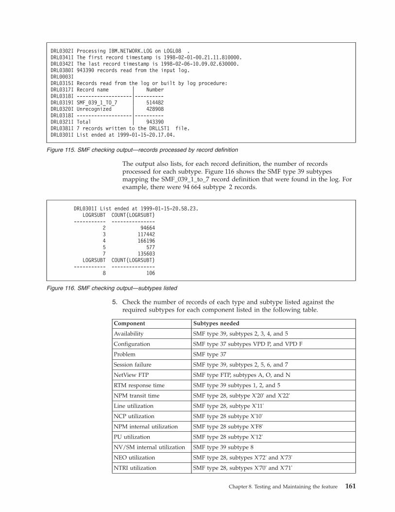
The output also lists, for each record definition, the number of records
processed for each subtype. Figure 116 shows the SMF type 39 subtypes
mapping the SMF_039_1_to_7 record definition that were found in the log. For
example, there were 94 664 subtype 2 records.
5. Check the number of records of each type and subtype listed against the
required subtypes for each component listed in the following table.
Component Subtypes needed
Availability SMF type 39, subtypes 2, 3, 4, and 5
Configuration SMF type 37 subtypes VPD P, and VPD F
Problem SMF type 37
Session failure SMF type 39, subtypes 2, 5, 6, and 7
NetView FTP SMF type FTP, subtypes A, O, and N
RTM response time SMF type 39 subtypes 1, 2, and 5
NPM transit time SMF type 28, subtype X'20' and X'22'
Line utilization SMF type 28, subtype X'11'
NCP utilization SMF type 28 subtype X'10'
NPM internal utilization SMF type 28 subtype X'F8'
PU utilization SMF type 28 subtype X'12'
NV/SM internal utilization SMF type 39 subtype 8
NEO utilization SMF type 28, subtypes X'72' and X'73'
NTRI utilization SMF type 28, subtypes X'70' and X'71'
DRL0302I Processing IBM.NETWORK.LOG on LOGL08 .
DRL0341I The first record timestamp is 1998-02-01-00.21.11.810000.
DRL0342I The last record timestamp is 1998-02-06-10.09.02.630000.
DRL0380I 943390 records read from the input log.
DRL0003I
DRL0315I Records read from the log or built by log procedure:
DRL0317I Record name | Number
DRL0318I -------------------|----------
DRL0319I SMF_039_1_TO_7 | 514482
DRL0320I Unrecognized | 428908
DRL0318I -------------------|----------
DRL0321I Total | 943390
DRL0381I 7 records written to the DRLLST1 file.
DRL0301I List ended at 1999-01-15-20.17.04.
Figure 115. SMF checking output—records processed by record definition
DRL0301I List ended at 1999-01-15-20.58.23.
LOGRSUBT COUNT(LOGRSUBT)
----------- ---------------
2 94664
3 117442
4 166196
5 577
7 135603
LOGRSUBT COUNT(LOGRSUBT)
----------- ---------------
8 106
Figure 116. SMF checking output—subtypes listed
Chapter 8. Testing and Maintaining the feature 161
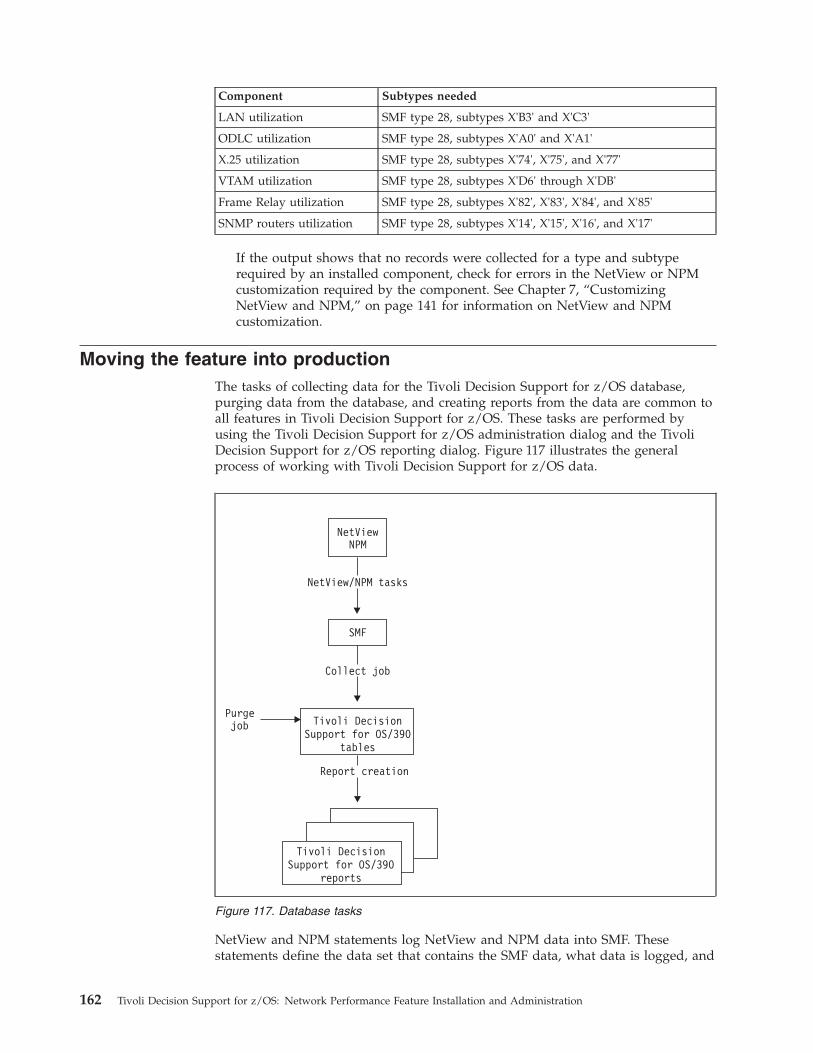
Component Subtypes needed
LAN utilization SMF type 28, subtypes X'B3' and X'C3'
ODLC utilization SMF type 28, subtypes X'A0' and X'A1'
X.25 utilization SMF type 28, subtypes X'74', X'75', and X'77'
VTAM utilization SMF type 28, subtypes X'D6' through X'DB'
Frame Relay utilization SMF type 28, subtypes X'82', X'83', X'84', and X'85'
SNMP routers utilization SMF type 28, subtypes X'14', X'15', X'16', and X'17'
If the output shows that no records were collected for a type and subtype
required by an installed component, check for errors in the NetView or NPM
customization required by the component. See Chapter 7, “Customizing
NetView and NPM,” on page 141 for information on NetView and NPM
customization.
Moving the feature into production
The tasks of collecting data for the Tivoli Decision Support for z/OS database,
purging data from the database, and creating reports from the data are common to
all features in Tivoli Decision Support for z/OS. These tasks are performed by
using the Tivoli Decision Support for z/OS administration dialog and the Tivoli
Decision Support for z/OS reporting dialog. Figure 117 illustrates the general
process of working with Tivoli Decision Support for z/OS data.
NetView and NPM statements log NetView and NPM data into SMF. These
statements define the data set that contains the SMF data, what data is logged, and
Figure 117. Database tasks
162 Tivoli Decision Support for z/OS: Network Performance Feature Installation and Administration
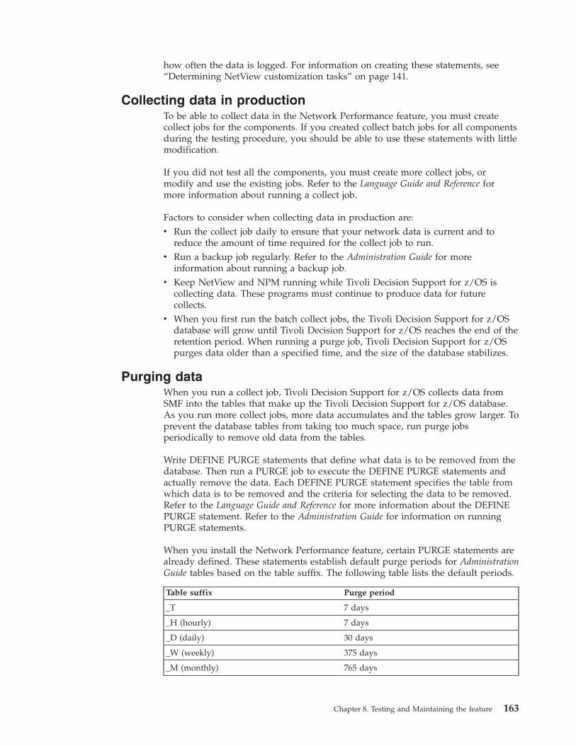
how often the data is logged. For information on creating these statements, see
“Determining NetView customization tasks” on page 141.
Collecting data in production
To be able to collect data in the Network Performance feature, you must create
collect jobs for the components. If you created collect batch jobs for all components
during the testing procedure, you should be able to use these statements with little
modification.
If you did not test all the components, you must create more collect jobs, or
modify and use the existing jobs. Refer to the Language Guide and Reference for
more information about running a collect job.
Factors to consider when collecting data in production are:
v Run the collect job daily to ensure that your network data is current and to
reduce the amount of time required for the collect job to run.
v Run a backup job regularly. Refer to the Administration Guide for more
information about running a backup job.
v Keep NetView and NPM running while Tivoli Decision Support for z/OS is
collecting data. These programs must continue to produce data for future
collects.
v When you first run the batch collect jobs, the Tivoli Decision Support for z/OS
database will grow until Tivoli Decision Support for z/OS reaches the end of the
retention period. When running a purge job, Tivoli Decision Support for z/OS
purges data older than a specified time, and the size of the database stabilizes.
Purging data
When you run a collect job, Tivoli Decision Support for z/OS collects data from
SMF into the tables that make up the Tivoli Decision Support for z/OS database.
As you run more collect jobs, more data accumulates and the tables grow larger. To
prevent the database tables from taking too much space, run purge jobs
periodically to remove old data from the tables.
Write DEFINE PURGE statements that define what data is to be removed from the
database. Then run a PURGE job to execute the DEFINE PURGE statements and
actually remove the data. Each DEFINE PURGE statement specifies the table from
which data is to be removed and the criteria for selecting the data to be removed.
Refer to the Language Guide and Reference for more information about the DEFINE
PURGE statement. Refer to the Administration Guide for information on running
PURGE statements.
When you install the Network Performance feature, certain PURGE statements are
already defined. These statements establish default purge periods for Administration
Guide tables based on the table suffix. The following table lists the default periods.
Table suffix Purge period
_T 7 days
_H (hourly) 7 days
_D (daily) 30 days
_W (weekly) 375 days
_M (monthly) 765 days
Chapter 8. Testing and Maintaining the feature 163
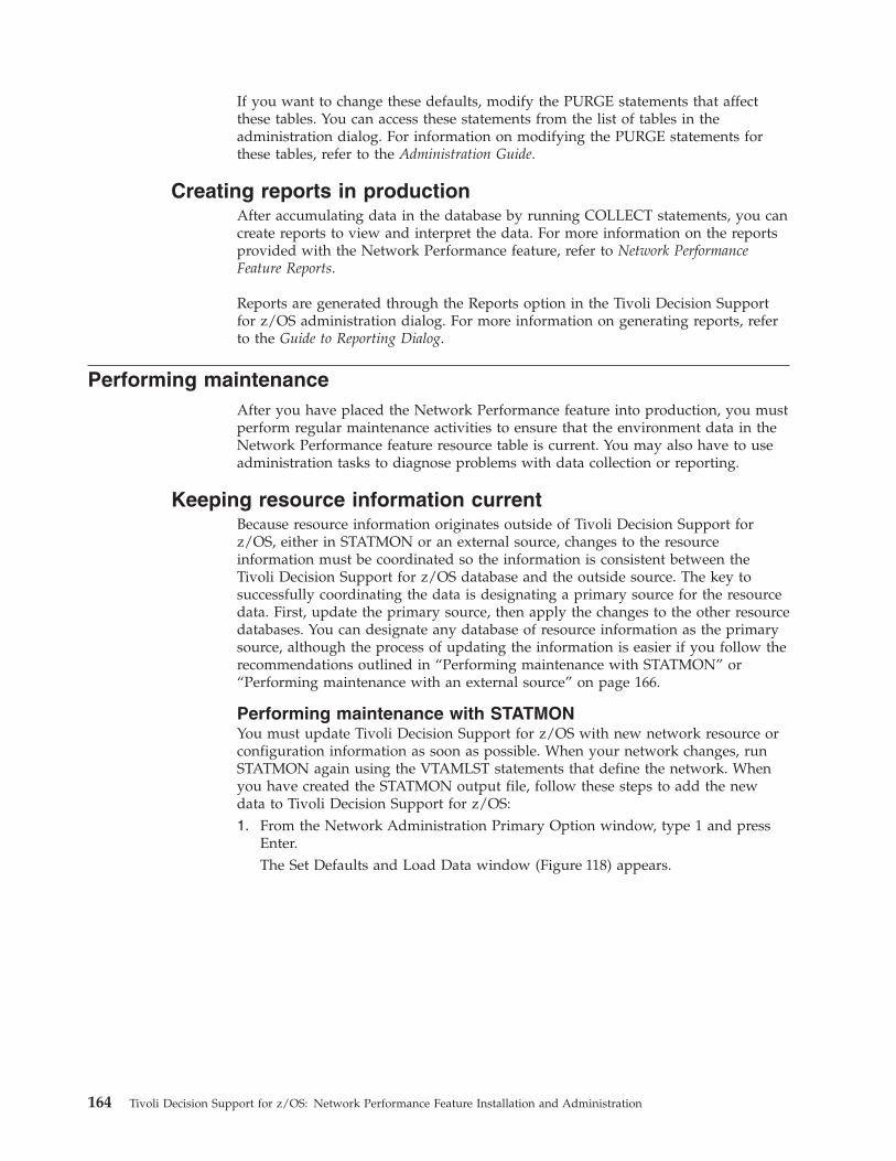
If you want to change these defaults, modify the PURGE statements that affect
these tables. You can access these statements from the list of tables in the
administration dialog. For information on modifying the PURGE statements for
these tables, refer to the Administration Guide.
Creating reports in production
After accumulating data in the database by running COLLECT statements, you can
create reports to view and interpret the data. For more information on the reports
provided with the Network Performance feature, refer to Network Performance
Feature Reports.
Reports are generated through the Reports option in the Tivoli Decision Support
for z/OS administration dialog. For more information on generating reports, refer
to the Guide to Reporting Dialog.
Performing maintenance
After you have placed the Network Performance feature into production, you must
perform regular maintenance activities to ensure that the environment data in the
Network Performance feature resource table is current. You may also have to use
administration tasks to diagnose problems with data collection or reporting.
Keeping resource information current
Because resource information originates outside of Tivoli Decision Support for
z/OS, either in STATMON or an external source, changes to the resource
information must be coordinated so the information is consistent between the
Tivoli Decision Support for z/OS database and the outside source. The key to
successfully coordinating the data is designating a primary source for the resource
data. First, update the primary source, then apply the changes to the other resource
databases. You can designate any database of resource information as the primary
source, although the process of updating the information is easier if you follow the
recommendations outlined in “Performing maintenance with STATMON” or
“Performing maintenance with an external source” on page 166.
Performing maintenance with STATMON
You must update Tivoli Decision Support for z/OS with new network resource or
configuration information as soon as possible. When your network changes, run
STATMON again using the VTAMLST statements that define the network. When
you have created the STATMON output file, follow these steps to add the new
data to Tivoli Decision Support for z/OS:
1. From the Network Administration Primary Option window, type 1 and press
Enter.
The Set Defaults and Load Data window (Figure 118) appears.
164 Tivoli Decision Support for z/OS: Network Performance Feature Installation and Administration
2. Move the cursor to the system you want to update, type 1, and press Enter.
The Edit Resource Defaults window appears (see Figure 40 on page 71).
3. Change the resource defaults if necessary, and press Enter.
The Load Options window (Figure 119) appears.
4. Type 3 and press Enter.
Tivoli Decision Support for z/OS merges the STATMON data into the existing
Tivoli Decision Support for z/OS database and the Network Administration
Primary Option window appears.
Tivoli Decision Support for z/OS combines the resource data using these rules:
Set Defaults and Load Data ROW 1 TO 2 OF 2
Type an action code next to the system ID for the data that you are
loading.
1 - Edit 2 - Delete 1 (for **NEW**) - Create
Action System ID System description
_ **NEW**
_ NETSYS1 Network domain 1
_ NETSYS2 Network domain 2
_ VENDSYS Vendor network
Command ===> ______________________________________________________________
F13=Help F15=Exit F19=Bkwd F20=Fwd F24=Cancel
Figure 118. Specifying the system to edit
Set Defaults and Load Data ROW 1 TO 2 OF 2
-----------------------------------------------------------------------------
| Load Options |
| |
| Select the way the resource data is loaded: |
| |
| 1 1. Load STATMON data. |
| 2. Load database table. |
| 3. Merge STATMON data and database table. |
| 4. Add STATMON data to the work table. |
| |
| Use the choices as follows: |
| |
| 1. Use this to build a new resource table. |
| 2. Use this to make minor changes to your resource table. |
| 3. Use this to update your resource table with new STATMON data. |
| 4. Use this to combine STATMON data from multiple systems. |
| |
| F1=Help F2=Split F9=Swap F12=Cancel |
-----------------------------------------------------------------------------
---------------------------
| Process system NETSYS1. |
---------------------------
Command ===> ______________________________________________________________
F1=Help F2=Split F3=Exit F7=Bkwd F8=Fwd F9=Swap F12=Cancel
Figure 119. Load Options window
Chapter 8. Testing and Maintaining the feature 165
v Tivoli Decision Support for z/OS adds resources in STATMON but not in Tivoli
Decision Support for z/OS and gives those resources a new (N) status.
v Tivoli Decision Support for z/OS ignores resources that are in STATMON, but
retains Tivoli Decision Support for z/OS data and gives those resources an old
(O) status.
v Tivoli Decision Support for z/OS retains resources that are in Tivoli Decision
Support for z/OS but not in STATMON and gives those resources a missing (D)
status.
When Tivoli Decision Support for z/OS ignores duplicated resources, it loses
changes to existing resources in VTAM (for example, assigning an existing cluster
to a different line). You must make these changes manually. See “Verifying resource
data” on page 98 for information on making these changes.
Performing maintenance with an external source
When you use an external source for resource information, that source is the
primary repository for resource data. Whenever the network changes, change the
external file first, then use that updated file to load the new data into the
NW_RESOURCE table. Import data from the external source whenever the
network resource information changes.
166 Tivoli Decision Support for z/OS: Network Performance Feature Installation and Administration
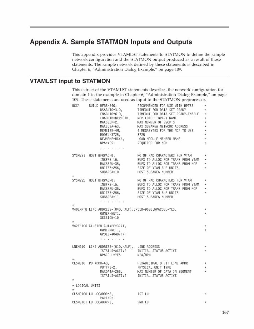
Appendix A. Sample STATMON Inputs and Outputs
This appendix provides VTAMLST statements to STATMON to define the sample
network configuration and the STATMON output produced as a result of those
statements. The sample network defined by these statements is described in
Chapter 6, “Administration Dialog Example,” on page 109.
VTAMLST input to STATMON
This extract of the VTAMLST statements describes the network configuration for
domain 1 in the example in Chapter 6, “Administration Dialog Example,” on page
109. These statements are used as input to the STATMON preprocessor.
UCX4 BUILD BFRS=240, RECOMMENDED FOR USE WITH HPTSS *
DSABLTO=3.0, TIMEOUT FOR DATA SET READY *
ENABLTO=6.0, TIMEOUT FOR DATA SET READY-ENABLE *
LOADLIB=NCPLOAD, NCP LOAD LIBRARY NAME *
MAXSSCP=2, MAX NUMBER OF SSCP’S *
MAXSUBA=63, MAX SUBAREA NETWORK ADDRESS *
MEMSIZE=4M, 4 MEGABYTES FOR THE NCP TO USE *
MODEL=3725, 3725 *
NEWNAME=UCX4, LOAD MODULE MEMBER NAME *
NPA=YES, REQUIRED FOR NPM *
. . . . . . .
SYSMVS1 HOST BFRPAD=0, NO OF PAD CHARACTERS FOR VTAM *
INBFRS=15, BUFS TO ALLOC FOR TRANS FROM VTAM *
MAXBFRU=35, BUFS TO ALLOC FOR TRANS FROM NCP *
UNITSZ=256, SIZE OF VTAM BUF UNITS *
SUBAREA=10 HOST SUBAREA NUMBER
*
SYSMVS2 HOST BFRPAD=0, NO OF PAD CHARACTERS FOR VTAM *
INBFRS=15, BUFS TO ALLOC FOR TRANS FROM VTAM *
MAXBFRU=35, BUFS TO ALLOC FOR TRANS FROM NCP *
UNITSZ=256, SIZE OF VTAM BUF UNITS *
SUBAREA=11 HOST SUBAREA NUMBER
. . . . . . .
*
V40LKNF8 LINE ADDRESS=(040,HALF),SPEED=9600,NPACOLL=YES, *
OWNER=NET1, *
SESSION=10
*
V42FFTC6 CLUSTER CUTYPE=3271, *
OWNER=NET1, *
GPOLL=40407F7F
. . . . . . .
LNEM010 LINE ADDRESS=(010,HALF), LINE ADDRESS *
ISTATUS=ACTIVE INITIAL STATUS ACTIVE *
NPACOLL=YES NPA/NPM
*
CLSM010 PU ADDR=A0, HEXADECIMAL 8 BIT LINE ADDR *
PUTYPE=2, PHYSICAL UNIT TYPE *
MAXDATA=265, MAX NUMBER OF DATA IN SEGMENT *
ISTATUS=ACTIVE INITIAL STATUS ACTIVE
*
* LOGICAL UNITS
*
CLSM0100 LU LOCADDR=2, 1ST LU *
PACING=1
CLSM0101 LU LOCADDR=3, 2ND LU *
167
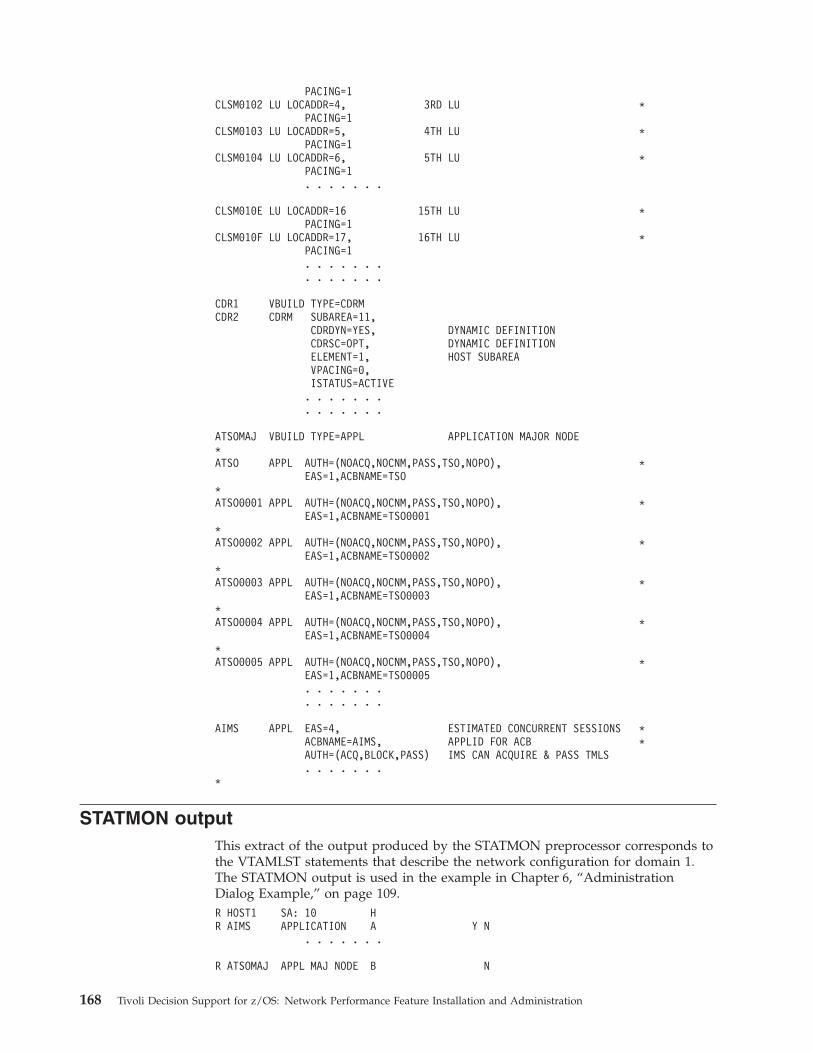
PACING=1
CLSM0102 LU LOCADDR=4, 3RD LU *
PACING=1
CLSM0103 LU LOCADDR=5, 4TH LU *
PACING=1
CLSM0104 LU LOCADDR=6, 5TH LU *
PACING=1
. . . . . . .
CLSM010E LU LOCADDR=16 15TH LU *
PACING=1
CLSM010F LU LOCADDR=17, 16TH LU *
PACING=1
. . . . . . .
. . . . . . .
CDR1 VBUILD TYPE=CDRM
CDR2 CDRM SUBAREA=11,
CDRDYN=YES, DYNAMIC DEFINITION
CDRSC=OPT, DYNAMIC DEFINITION
ELEMENT=1, HOST SUBAREA
VPACING=0,
ISTATUS=ACTIVE
. . . . . . .
. . . . . . .
ATSOMAJ VBUILD TYPE=APPL APPLICATION MAJOR NODE
*
ATSO APPL AUTH=(NOACQ,NOCNM,PASS,TSO,NOPO), *
EAS=1,ACBNAME=TSO
*
ATSO0001 APPL AUTH=(NOACQ,NOCNM,PASS,TSO,NOPO), *
EAS=1,ACBNAME=TSO0001
*
ATSO0002 APPL AUTH=(NOACQ,NOCNM,PASS,TSO,NOPO), *
EAS=1,ACBNAME=TSO0002
*
ATSO0003 APPL AUTH=(NOACQ,NOCNM,PASS,TSO,NOPO), *
EAS=1,ACBNAME=TSO0003
*
ATSO0004 APPL AUTH=(NOACQ,NOCNM,PASS,TSO,NOPO), *
EAS=1,ACBNAME=TSO0004
*
ATSO0005 APPL AUTH=(NOACQ,NOCNM,PASS,TSO,NOPO), *
EAS=1,ACBNAME=TSO0005
. . . . . . .
. . . . . . .
AIMS APPL EAS=4, ESTIMATED CONCURRENT SESSIONS *
ACBNAME=AIMS, APPLID FOR ACB *
AUTH=(ACQ,BLOCK,PASS) IMS CAN ACQUIRE & PASS TMLS
. . . . . . .
*
STATMON output
This extract of the output produced by the STATMON preprocessor corresponds to
the VTAMLST statements that describe the network configuration for domain 1.
The STATMON output is used in the example in Chapter 6, “Administration
Dialog Example,” on page 109.
R HOST1 SA: 10 H
R AIMS APPLICATION A Y N
. . . . . . .
R ATSOMAJ APPL MAJ NODE B N
168 Tivoli Decision Support for z/OS: Network Performance Feature Installation and Administration
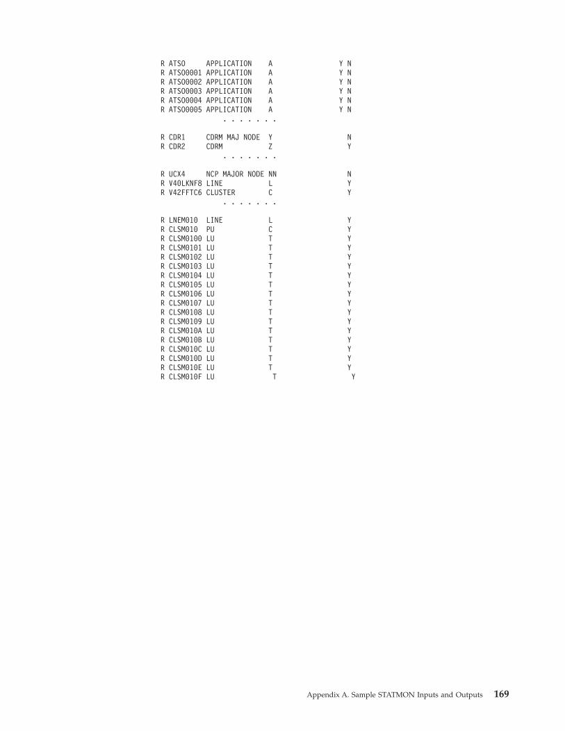
R ATSO APPLICATION A Y N
R ATSO0001 APPLICATION A Y N
R ATSO0002 APPLICATION A Y N
R ATSO0003 APPLICATION A Y N
R ATSO0004 APPLICATION A Y N
R ATSO0005 APPLICATION A Y N
. . . . . . .
R CDR1 CDRM MAJ NODE Y N
R CDR2 CDRM Z Y
. . . . . . .
R UCX4 NCP MAJOR NODE NN N
R V40LKNF8 LINE L Y
R V42FFTC6 CLUSTER C Y
. . . . . . .
R LNEM010 LINE L Y
R CLSM010 PU C Y
R CLSM0100 LU T Y
R CLSM0101 LU T Y
R CLSM0102 LU T Y
R CLSM0103 LU T Y
R CLSM0104 LU T Y
R CLSM0105 LU T Y
R CLSM0106 LU T Y
R CLSM0107 LU T Y
R CLSM0108 LU T Y
R CLSM0109 LU T Y
R CLSM010A LU T Y
R CLSM010B LU T Y
R CLSM010C LU T Y
R CLSM010D LU T Y
R CLSM010E LU T Y
R CLSM010F LU T Y
Appendix A. Sample STATMON Inputs and Outputs 169

170 Tivoli Decision Support for z/OS: Network Performance Feature Installation and Administration
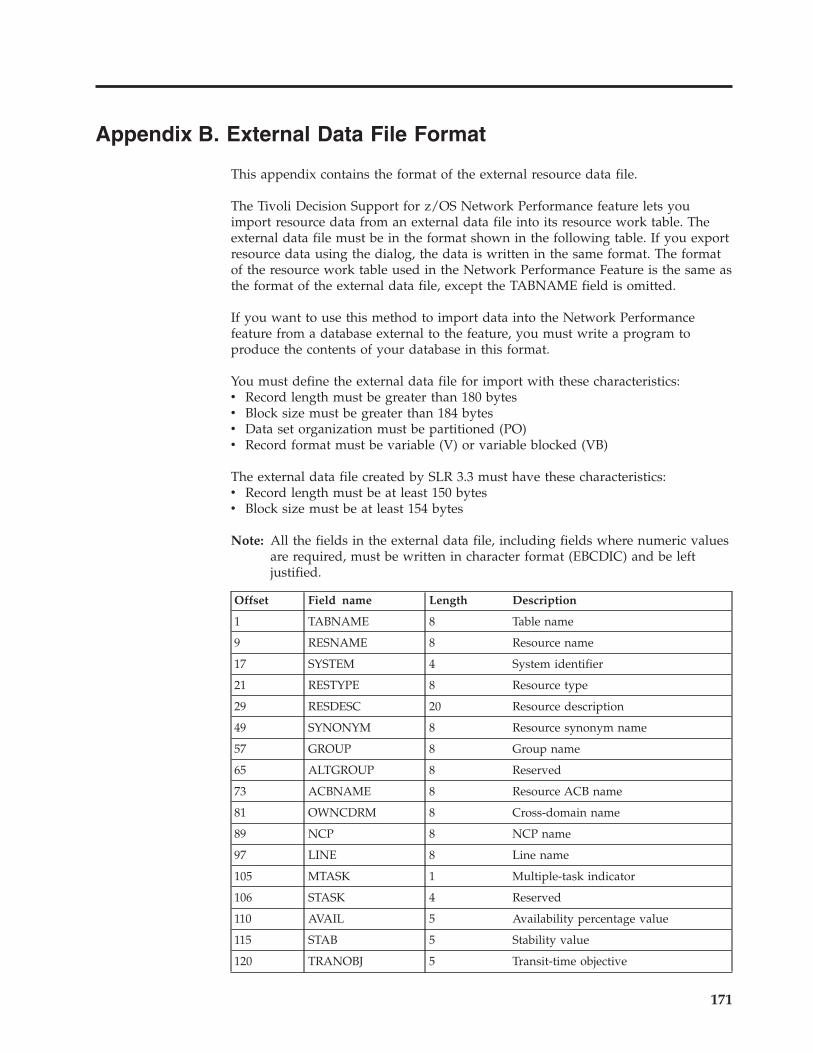
Appendix B. External Data File Format
This appendix contains the format of the external resource data file.
The Tivoli Decision Support for z/OS Network Performance feature lets you
import resource data from an external data file into its resource work table. The
external data file must be in the format shown in the following table. If you export
resource data using the dialog, the data is written in the same format. The format
of the resource work table used in the Network Performance Feature is the same as
the format of the external data file, except the TABNAME field is omitted.
If you want to use this method to import data into the Network Performance
feature from a database external to the feature, you must write a program to
produce the contents of your database in this format.
You must define the external data file for import with these characteristics:
v Record length must be greater than 180 bytes
v Block size must be greater than 184 bytes
v Data set organization must be partitioned (PO)
v Record format must be variable (V) or variable blocked (VB)
The external data file created by SLR 3.3 must have these characteristics:
v Record length must be at least 150 bytes
v Block size must be at least 154 bytes
Note: All the fields in the external data file, including fields where numeric values
are required, must be written in character format (EBCDIC) and be left
justified.
Offset Field name Length Description
1 TABNAME 8 Table name
9 RESNAME 8 Resource name
17 SYSTEM 4 System identifier
21 RESTYPE 8 Resource type
29 RESDESC 20 Resource description
49 SYNONYM 8 Resource synonym name
57 GROUP 8 Group name
65 ALTGROUP 8 Reserved
73 ACBNAME 8 Resource ACB name
81 OWNCDRM 8 Cross-domain name
89 NCP 8 NCP name
97 LINE 8 Line name
105 MTASK 1 Multiple-task indicator
106 STASK 4 Reserved
110 AVAIL 5 Availability percentage value
115 STAB 5 Stability value
120 TRANOBJ 5 Transit-time objective
171
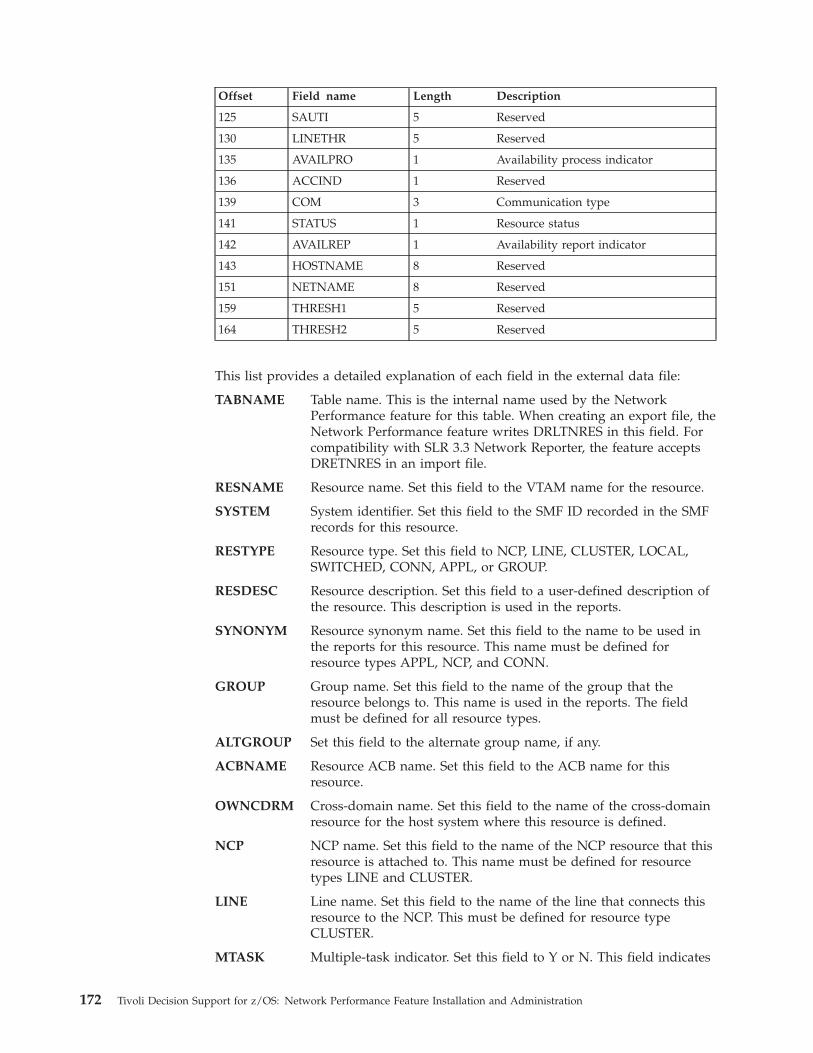
Offset Field name Length Description
125 SAUTI 5 Reserved
130 LINETHR 5 Reserved
135 AVAILPRO 1 Availability process indicator
136 ACCIND 1 Reserved
139 COM 3 Communication type
141 STATUS 1 Resource status
142 AVAILREP 1 Availability report indicator
143 HOSTNAME 8 Reserved
151 NETNAME 8 Reserved
159 THRESH1 5 Reserved
164 THRESH2 5 Reserved
This list provides a detailed explanation of each field in the external data file:
TABNAME Table name. This is the internal name used by the Network
Performance feature for this table. When creating an export file, the
Network Performance feature writes DRLTNRES in this field. For
compatibility with SLR 3.3 Network Reporter, the feature accepts
DRETNRES in an import file.
RESNAME Resource name. Set this field to the VTAM name for the resource.
SYSTEM System identifier. Set this field to the SMF ID recorded in the SMF
records for this resource.
RESTYPE Resource type. Set this field to NCP, LINE, CLUSTER, LOCAL,
SWITCHED, CONN, APPL, or GROUP.
RESDESC Resource description. Set this field to a user-defined description of
the resource. This description is used in the reports.
SYNONYM Resource synonym name. Set this field to the name to be used in
the reports for this resource. This name must be defined for
resource types APPL, NCP, and CONN.
GROUP Group name. Set this field to the name of the group that the
resource belongs to. This name is used in the reports. The field
must be defined for all resource types.
ALTGROUP Set this field to the alternate group name, if any.
ACBNAME Resource ACB name. Set this field to the ACB name for this
resource.
OWNCDRM Cross-domain name. Set this field to the name of the cross-domain
resource for the host system where this resource is defined.
NCP NCP name. Set this field to the name of the NCP resource that this
resource is attached to. This name must be defined for resource
types LINE and CLUSTER.
LINE Line name. Set this field to the name of the line that connects this
resource to the NCP. This must be defined for resource type
CLUSTER.
MTASK Multiple-task indicator. Set this field to Y or N. This field indicates
172 Tivoli Decision Support for z/OS: Network Performance Feature Installation and Administration
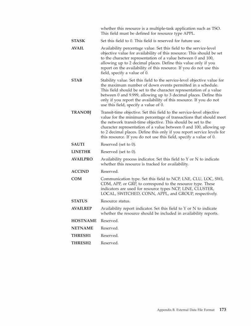
whether this resource is a multiple-task application such as TSO.
This field must be defined for resource type APPL.
STASK Set this field to 0. This field is reserved for future use.
AVAIL Availability percentage value. Set this field to the service-level
objective value for availability of this resource. This should be set
to the character representation of a value between 0 and 100,
allowing up to 2 decimal places. Define this value only if you
report on the availability of this resource. If you do not use this
field, specify a value of 0.
STAB Stability value. Set this field to the service-level objective value for
the maximum number of down events permitted in a schedule.
This field should be set to the character representation of a value
between 0 and 9.999, allowing up to 3 decimal places. Define this
only if you report the availability of this resource. If you do not
use this field, specify a value of 0.
TRANOBJ Transit-time objective. Set this field to the service-level objective
value for the minimum percentage of transactions that should meet
the network transit-time objective. This should be set to the
character representation of a value between 0 and 100, allowing up
to 2 decimal places. Define this only if you report service levels for
this resource. If you do not use this field, specify a value of 0.
SAUTI Reserved (set to 0).
LINETHR Reserved (set to 0).
AVAILPRO Availability process indicator. Set this field to Y or N to indicate
whether this resource is tracked for availability.
ACCIND Reserved.
COM Communication type. Set this field to NCP, LNE, CLU, LOC, SWI,
CDM, APP, or GRP, to correspond to the resource type. These
indicators are used for resource types NCP, LINE, CLUSTER,
LOCAL, SWITCHED, CONN, APPL, and GROUP, respectively.
STATUS Resource status.
AVAILREP Availability report indicator. Set this field to Y or N to indicate
whether the resource should be included in availability reports.
HOSTNAME Reserved.
NETNAME Reserved.
THRESH1 Reserved.
THRESH2 Reserved.
Appendix B. External Data File Format 173

174 Tivoli Decision Support for z/OS: Network Performance Feature Installation and Administration
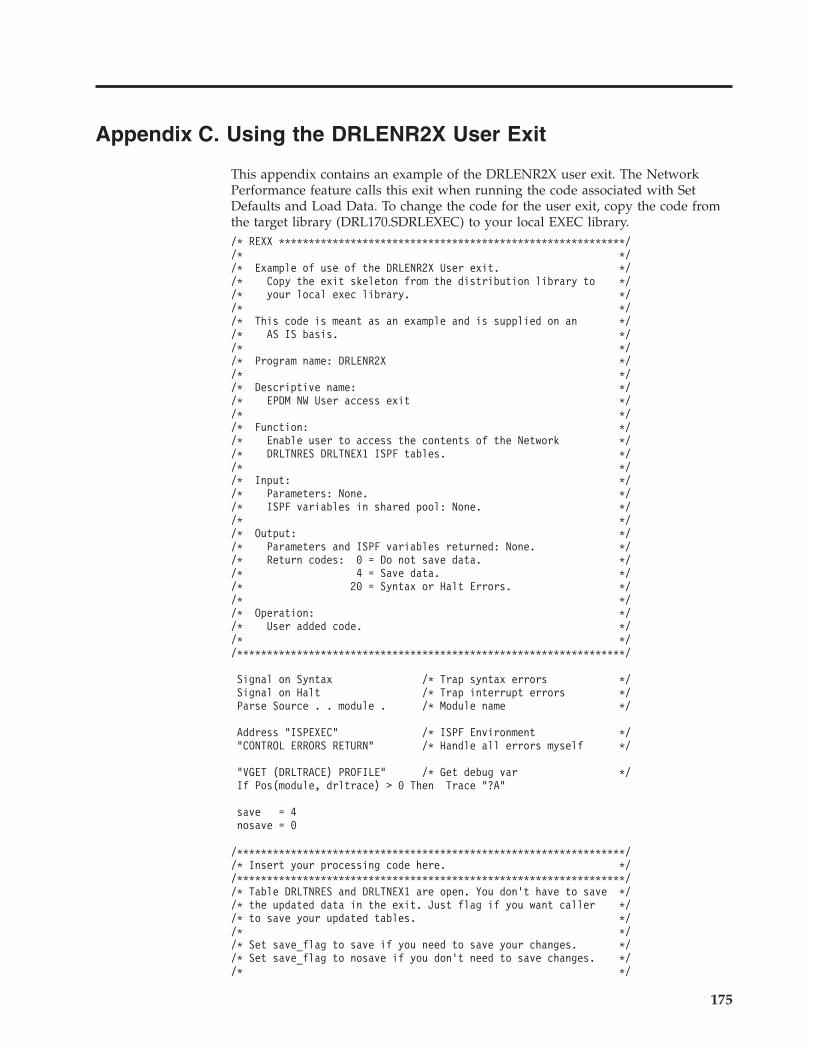
Appendix C. Using the DRLENR2X User Exit
This appendix contains an example of the DRLENR2X user exit. The Network
Performance feature calls this exit when running the code associated with Set
Defaults and Load Data. To change the code for the user exit, copy the code from
the target library (DRL170.SDRLEXEC) to your local EXEC library.
/* REXX **********************************************************/
/* */
/* Example of use of the DRLENR2X User exit. */
/* Copy the exit skeleton from the distribution library to */
/* your local exec library. */
/* */
/* This code is meant as an example and is supplied on an */
/* AS IS basis. */
/* */
/* Program name: DRLENR2X */
/* */
/* Descriptive name: */
/* EPDM NW User access exit */
/* */
/* Function: */
/* Enable user to access the contents of the Network */
/* DRLTNRES DRLTNEX1 ISPF tables. */
/* */
/* Input: */
/* Parameters: None. */
/* ISPF variables in shared pool: None. */
/* */
/* Output: */
/* Parameters and ISPF variables returned: None. */
/* Return codes: 0 = Do not save data. */
/* 4 = Save data. */
/* 20 = Syntax or Halt Errors. */
/* */
/* Operation: */
/* User added code. */
/* */
/*****************************************************************/
Signal on Syntax /* Trap syntax errors */
Signal on Halt /* Trap interrupt errors */
Parse Source . . module . /* Module name */
Address "ISPEXEC" /* ISPF Environment */
"CONTROL ERRORS RETURN" /* Handle all errors myself */
"VGET (DRLTRACE) PROFILE" /* Get debug var */
If Pos(module, drltrace) > 0 Then Trace "?A"
save = 4
nosave = 0
/*****************************************************************/
/* Insert your processing code here. */
/*****************************************************************/
/* Table DRLTNRES and DRLTNEX1 are open. You don’t have to save */
/* the updated data in the exit. Just flag if you want caller */
/* to save your updated tables. */
/* */
/* Set save_flag to save if you need to save your changes. */
/* Set save_flag to nosave if you don’t need to save changes. */
/* */
175
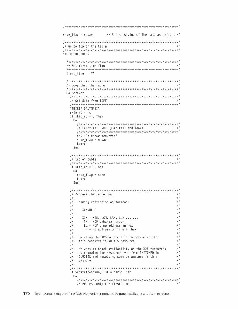
/*****************************************************************/
save_flag = nosave /* Set no saving of the data as default */
/*****************************************************************/
/* Go to top of the table */
/*****************************************************************/
"TBTOP DRLTNRES"
/***************************************************************/
/* Set first time flag */
/***************************************************************/
first_time = ’Y’
/***************************************************************/
/* Loop thru the table */
/***************************************************************/
Do Forever
/*************************************************************/
/* Get data from ISPF */
/*************************************************************/
"TBSKIP DRLTNRES"
skip_rc = rc
If skip_rc > 8 Then
Do
/*********************************************************/
/* Error in TBSKIP just tell and leave */
/*********************************************************/
Say ’An error occurred’
save_flag = nosave
Leave
End
/*************************************************************/
/* End of table */
/*************************************************************/
If skip_rc = 8 Then
Do
save_flag = save
Leave
End
/*************************************************************/
/* Process the table row: */
/* */
/* Naming convention as follows: */
/* */
/* XXXNNLLP */
/* */
/* XXX = X25, LON, LAX, LUX ....... */
/* NN = NCP subarea number */
/* LL = NCP Line address in hex */
/* P = PU address on line in hex */
/* */
/* By using the X25 we are able to determine that */
/* this resource is an X25 resource. */
/* */
/* We want to track availability on the X25 resources, */
/* by changing the resource type from SWITCHED to */
/* CLUSTER and resetting some parameters in this */
/* example. */
/* */
/*************************************************************/
If Substr(resname,1,3) = ’X25’ Then
Do
/*********************************************************/
/* Process only the first time */
176 Tivoli Decision Support for z/OS: Network Performance Feature Installation and Administration
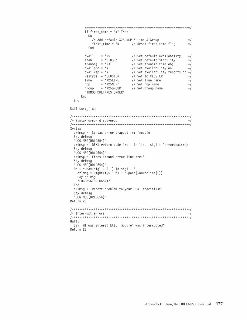
/*********************************************************/
If first_time = ’Y’ Then
Do
/* Add default X25 NCP & Line & Group */
first_time = ’N’ /* Reset first time flag */
End
avail = ’95’ /* Set default availability */
stab = ’0.033’ /* Set default stability */
tranobj = ’93’ /* Set transit time obj */
availpro = ’Y’ /* Set availability on */
availrep = ’Y’ /* Set availability reports on */
restype = ’CLUSTER’ /* Set to CLUSTER */
line = ’X25LINE’ /* Set line name */
ncp = ’X25NCP’ /* Set ncp name */
group = ’X25GROUP’ /* Set group name */
"TBMOD DRLTNRES ORDER"
End
End
Exit save_flag
/*****************************************************************/
/* Syntax error discovered */
/*****************************************************************/
Syntax:
drlmsg = ’Syntax error trapped in: ’module
Say drlmsg
"LOG MSG(DRLD654)"
drlmsg = ’REXX return code ’rc ’ in line ’sigl’: ’errortext(rc)
Say drlmsg
"LOG MSG(DRLD654)"
drlmsg = ’Lines around error line are:’
Say drlmsg
"LOG MSG(DRLD654)"
Do i = Max(sigl - 5,1) To sigl + 5
drlmsg = Right(i,5,’0’)’: ’Space(Sourceline(i))
Say drlmsg
"LOG MSG(DRLD654)"
End
drlmsg = ’Report problem to your P.R. specialist’
Say drlmsg
"LOG MSG(DRLD654)"
Return 20
/*****************************************************************/
/* Interrupt errors */
/*****************************************************************/
Halt:
Say ’HI was entered EXEC ’module’ was interrupted’
Return 20
Appendix C. Using the DRLENR2X User Exit 177

178 Tivoli Decision Support for z/OS: Network Performance Feature Installation and Administration
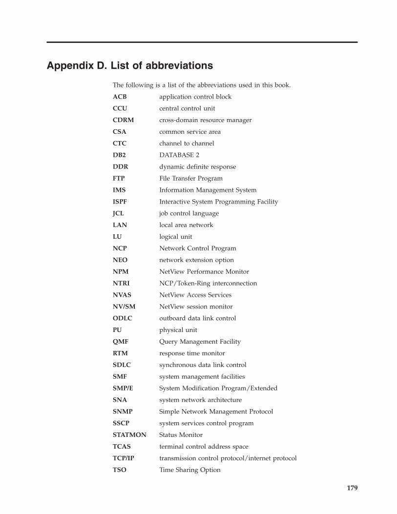
Appendix D. List of abbreviations
The following is a list of the abbreviations used in this book.
ACB application control block
CCU central control unit
CDRM cross-domain resource manager
CSA common service area
CTC channel to channel
DB2 DATABASE 2
DDR dynamic definite response
FTP File Transfer Program
IMS Information Management System
ISPF Interactive System Programming Facility
JCL job control language
LAN local area network
LU logical unit
NCP Network Control Program
NEO network extension option
NPM NetView Performance Monitor
NTRI NCP/Token-Ring interconnection
NVAS NetView Access Services
NV/SM NetView session monitor
ODLC outboard data link control
PU physical unit
QMF Query Management Facility
RTM response time monitor
SDLC synchronous data link control
SMF system management facilities
SMP/E System Modification Program/Extended
SNA system network architecture
SNMP Simple Network Management Protocol
SSCP system services control program
STATMON Status Monitor
TCAS terminal control address space
TCP/IP transmission control protocol/internet protocol
TSO Time Sharing Option
179

UDP User Datagram Protocol
VPD vital product data
VTAM Virtual Telecommunication Access Method
180 Tivoli Decision Support for z/OS: Network Performance Feature Installation and Administration
Notices
This information was developed for products and services offered in the U.S.A.
IBM may not offer the products, services, or features discussed in this document in
other countries. Consult your local IBM representative for information on the
products and services currently available in your area. Any reference to an IBM
product, program, or service is not intended to state or imply that only that IBM
product, program, or service may be used. Any functionally equivalent product,
program, or service that does not infringe any IBM intellectual property right may
be used instead. However, it is the user’s responsibility to evaluate and verify the
operation of any non-IBM product, program, or service.
IBM may have patents or pending patent applications covering subject matter
described in this document. The furnishing of this document does not give you
any license to these patents. You can send license inquiries, in writing, to:
IBM Director of Licensing
IBM Corporation
North Castle Drive
Armonk, NY 10504-1785 U.S.A.
For license inquiries regarding double-byte (DBCS) information, contact the IBM
Intellectual Property Department in your country or send inquiries, in writing, to:
IBM World Trade Asia Corporation
Licensing
2-31 Roppongi 3-chome, Minato-ku
Tokyo 106, Japan
The following paragraph does not apply to the United Kingdom or any other
country where such provisions are inconsistent with local law:
INTERNATIONAL BUSINESS MACHINES CORPORATION PROVIDES THIS
PUBLICATION ″AS IS″ WITHOUT WARRANTY OF ANY KIND, EITHER
EXPRESS OR IMPLIED, INCLUDING, BUT NOT LIMITED TO, THE IMPLIED
WARRANTIES OF NON-INFRINGEMENT, MERCHANTABILITY OR FITNESS
FOR A PARTICULAR PURPOSE.
Some states do not allow disclaimer of express or implied warranties in certain
transactions, therefore, this statement might not apply to you.
This information could include technical inaccuracies or typographical errors.
Changes are periodically made to the information herein; these changes will be
incorporated in new editions of the publication. IBM may make improvements
and/or changes in the product(s) and/or the program(s) described in this
publication at any time without notice.
Any references in this information to non-IBM Web sites are provided for
convenience only and do not in any manner serve as an endorsement of those Web
sites. The materials at those Web sites are not part of the materials for this IBM
product and use of those Web sites is at your own risk.
181

IBM may use or distribute any of the information you supply in any way it
believes appropriate without incurring any obligation to you.
Licensees of this program who wish to have information about it for the purpose
of enabling: (i) the exchange of information between independently created
programs and other programs (including this one) and (ii) the mutual use of the
information which has been exchanged, should contact:
IBM Corporation
2Z4A/101
11400 Burnet Road
Austin, TX 78758 U.S.A.
Such information may be available, subject to appropriate terms and conditions,
including in some cases payment of a fee.
The licensed program described in this document and all licensed material
available for it are provided by IBM under terms of the IBM Customer Agreement,
IBM International Program License Agreement or any equivalent agreement
between us.
Any performance data contained herein was determined in a controlled
environment. Therefore, the results obtained in other operating environments may
vary significantly. Some measurements may have been made on development-level
systems and there is no guarantee that these measurements will be the same on
generally available systems. Furthermore, some measurement may have been
estimated through extrapolation. Actual results may vary. Users of this document
should verify the applicable data for their specific environment.
Information concerning non-IBM products was obtained from the suppliers of
those products, their published announcements or other publicly available sources.
IBM has not tested those products and cannot confirm the accuracy of
performance, compatibility or any other claims related to non-IBM products.
Questions on the capabilities of non-IBM products should be addressed to the
suppliers of those products.
All statements regarding IBM’s future direction or intent are subject to change or
withdrawal without notice, and represent goals and objectives only.
All IBM prices shown are IBM’s suggested retail prices, are current and are subject
to change without notice. Dealer prices may vary.
This information is for planning purposes only. The information herein is subject to
change before the products described become available.
This information contains examples of data and reports used in daily business
operations. To illustrate them as completely as possible, the examples include the
names of individuals, companies, brands, and products. All of these names are
fictitious and any similarity to the names and addresses used by an actual business
enterprise is entirely coincidental.
COPYRIGHT LICENSE:
This information contains sample application programs in source language, which
illustrate programming techniques on various operating platforms. You may copy,
modify, and distribute these sample programs in any form without payment to
182 Tivoli Decision Support for z/OS: Network Performance Feature Installation and Administration
IBM, for the purposes of developing, using, marketing or distributing application
programs conforming to the application programming interface for the operating
platform for which the sample programs are written. These examples have not
been thoroughly tested under all conditions. IBM, therefore, cannot guarantee or
imply reliability, serviceability, or function of these programs. You may copy,
modify, and distribute these sample programs in any form without payment to
IBM for the purposes of developing, using, marketing, or distributing application
programs conforming to IBM‘s application programming interfaces.
If you are viewing this information in softcopy form, the photographs and color
illustrations might not display.
Trademarks
AS/400, CICS, DB2, DB2 Universal Database, eServer, iSeries, IBM, the IBM logo,
IMS, Lotus, MVS, NetView, OS/390, Passport Advantage, pSeries, Tivoli, QMF,
Rational, Redbook, VTAM, WebSphere, z/OS, and zSeries are trademarks or
registered trademarks of International Business Machines Corporation in the
United States, other countries, or both.
Linux is a registered trademark of Linus Torvalds in the United States, other
countries, or both.
Microsoft, Windows, Windows NT, and the Windows logo are trademarks of
Microsoft Corporation in the United States, other countries, or both.
UNIX is a registered trademark of The Open Group in the United States and other
countries.
Other company, product, and service names may be trademarks or service marks
of others.
Notices 183

184 Tivoli Decision Support for z/OS: Network Performance Feature Installation and Administration
Glossary
A
administration. A Tivoli Decision Support for z/OS
task that includes maintaining the database, updating
environment information, and ensuring the accuracy of
data collected.
administration dialog. A set of host windows used to
administer Tivoli Decision Support for z/OS.
C
code converter. A Tivoli Decision Support for z/OS
table used to convert network problem codes to text
descriptions.
collect. A process used by Tivoli Decision Support for
z/OS to read data from input log data sets, interpret
records in the data set, and store the data in DB2 tables
in the Tivoli Decision Support for z/OS database.
component. An optionally installable part of a Tivoli
Decision Support for z/OS feature.
cross-connection. A link between two network
domains.
E
environment information. All of the information that
is added to the log data to create reports. This
information can include data such as performance
groups, shift periods, installation definitions, and so on.
I
information category. One of the divisions of
information the Network Performance feature
processes. Each information category consists of one or
more components.
L
log collector. A Tivoli Decision Support for z/OS
program that processes log data sets and provides
other Tivoli Decision Support for z/OS services.
log collector language. Tivoli Decision Support for
z/OS statements used to supply definitions to and
invoke services of the log collector.
log data set. Any sequential data set that is used as
input to Tivoli Decision Support for z/OS.
lookup table. A Tivoli Decision Support for z/OS DB2
table that contains grouping, conversion, or substitution
information.
N
network administration dialog. A set of host
windows used to administer the NW_RESOURCE
table.
R
record definition. The description of a record type
contained in the log data sets used by Tivoli Decision
Support for z/OS, including detailed record layout and
data formats.
report definition language. Tivoli Decision Support
for z/OS statements used to define reports and report
groups.
report group. A collection of Tivoli Decision Support
for z/OS reports that can be referred to by a single
name.
reporting dialog. A set of host or workstation
windows used to request reports.
resource group. A collection of network resources that
are identified as belonging to a particular department
or division. Resources are organized into groups to
reflect the structure of an organization.
resource information. Environment information that
describes the elements in a network.
retention period. The period of time a Tivoli Decision
Support for z/OS database table retains data before
purging it.
T
target. In an update definition, the DB2 table in which
Tivoli Decision Support for z/OS stores data from the
source record or table.
threshold. The maximum or minimum acceptable
level of utilization. Utilization measurements are
compared with threshold levels.
Tivoli Decision Support for z/OS database. A set of
DB2 tables that contain the environment information
and performance data used by Tivoli Decision Support
for z/OS to generate reports.
185

186 Tivoli Decision Support for z/OS: Network Performance Feature Installation and Administration
Index
Aaccessibility xii
administrationdefinition 6
dialog functions 61
dialog tasks, overview 67
dialog, need for 61
overview 61
Primary Option window 69
process 9
alternate resource group 17
alternate resource name 17
application resources 88
application synonym, need for 18
availabilityincluding resources in processing 19, 30
including resources in reporting 20, 30
planning tasks 30
availability category 4
AVAILABILITY_PARM table 25
CChange Application Resource Data window 90
Change Cluster Resource Data window 94
change commandsdeleteall 87
save 86
Change Cross-connection Resource Data window 95
Change function key 85
Change Group Resource Data window 96
Change Line Resource Data window 93
Change Local Resource Data window 97
Change NCP Resource Data window 92
Change Resource Data window 82
Change Switched Resource Data window 98
cluster resources 88
code, installing 49
collect interval 39
componentsinformation category list 10
installing 50
list 4
planning for 10, 11
Components window 50
Configuration component 32
Confirm Changes pop-up 90
Confirm Selection pop-up 98
Create a Database Update Job window 74
cross-connection resources, availability planning 32
cross-domain connection synonym 19
cross-network connection synonym 19
customer support xii
customizing NetView and NPM 141, 145
NetViewavailability component 31
NV/SM utilization component 40
RTM response time component 34
NPMFrame Relay utilization component 43
customizing NetView and NPM (continued)NPM (continued)
LAN utilization component 43, 47
line utilization component 38
NCP utilization component 39
NEO utilization component 41
NPM transit time component 36
NTRI utilization component 42
ODLC utilization component 44
VTAM utilization component 44
X.25 utilization component 46
Ddata
domain 2 data 131
loading from a multiple-domain network 75
loading from a single network domain 68
loading from an external source 102
loading into the NW_RESOURCE table 68
loading process diagram 102
databaseupdating 73
day type, identifying 22
DAY_OF_WEEK table 22
default valuesin lookup tables 14
deleteall command 87
deleting resource entriesin groups 87
individually 86
describing resourcesfor availability 30
for frame relay utilization 43
for NCP utilization 38
for NEO utilization 40
for NPM transit time 35
for NTRI utilization 42
for ODLC utilization 44
for RTM response time 33
for X.25 utilization 45
domain 2 data 131
EEdit resource defaults window 71, 103
environment dataloading from an external source 102
loading from STATMON 68
modifying 77
planning for 14
role of 6
exported datadata set naming convention 107
Ffile transfer category 4
Frame Relay utilization component 42
FTP component, planning for 32
187
function keysCancel 87
Change 85
Search1 82
Search2 83
Gglobal search character 83
groups, resourcealternate 17
establishing 16
planning for componentsavailability 30
NCP utilization 38
NPM transit time 35
RTM response time 33
Iincluding resources
in availability processing 10, 19, 30
in availability reporting 20, 30
information categories 4
list of components 10
selecting 10
installationof code 10
of components 50
installation and administration process 9
Installation Options pop-up 51
interval, collect 39
LLAN utilization component 43, 46
line resources 88
Line utilization component 36
Load Options window 72
loadingdata from a multiple-domain network 75
data from a single network domain 68
LookAt message retrieval tool xi
lookup tablesAVAILABILITY_PARM 25
DAY_OF_WEEK 22
NW_ALERT_DESC 28
NW_ALERT_TYPE 27
NW_FAILURE_CODE 28
NW_GENERAL_CAUSE 27
NW_PROBABLE_CAUSE 28
NW_PRODUCT_ID 26
NW_SPECIFIC_CAUSE 27
NW_THRESHOLD 41
PERIOD_PLAN 23
SCHEDULE 24
SPECIAL_DAY 22
Lookup Tables pop-up 52
Mmaintenance
of environment information 14
MAPSESS definition 34
message retrieval tool, LookAt xi
Nname
NetView 39
NPM 39
names, resourcealternate 17
synonym 18
planning for availability 31
planning for frame relay utilization 43
planning for NCP utilization 38
planning for NEO utilization 40
planning for NPM transit time 35
planning for NTRI utilization 42
planning for ODLC utilization 44
planning for RTM response time 33
planning for X.25 utilization 45
NCP synonym names 19
NCP utilization component 38
NEO utilization component 40
NetView FTP component 32
network environmentdata from STATMON 68
Network Performance featureadministration dialog 61
overview 2
task list 7
normal operation 112
NPMcustomization for components
Frame Relay utilization 43
LAN utilization 43, 47
line utilization 38
NCP utilization 39
NEO utilization 41
NPM transit time 36
NTRI utilization 42
ODLC utilization 44
VTAM utilization 44
X.25 utilization 46
customizing 31
interval, defining 34
name 39
synonym conversions 18, 40
NPM internal utilization component 39
NPM transit time 34
NTRI utilization component 42
NW_ALERT_DESC table 28
NW_ALERT_TYPE table 27
NW_FAILURE_CODE table 29, 33
NW_GENERAL_CAUSE table 27
NW_PROBABLE_CAUSE table 28
NW_PRODUCT_ID table 26, 32
NW_SPECIFIC_CAUSE table 27
NW_THRESHOLD tableline utilization 37
NEO utilization 40
planning 22
X.25 utilization 45
NWPROBLEM18 report 32
Oobjectives, service level
planning for availability 31
planning for NPM transit time 35
planning for RTM response time 33
188 Tivoli Decision Support for z/OS: Network Performance Feature Installation and Administration
ODLC utilization component 44
online publications xii
ordering publications xii
overview, administration dialog tasks 67
PPCLASS definition 34
period information 22
PERIOD_PLAN table 23
planningcomponent tasks, planning for
Availability 30
Configuration 32
frame relay utilization 42
LAN utilization 43, 46
Line utilization 36
NCP utilization 38
NEO utilization 40
NetView FTP 32
NPM internal utilization 39
NPM transit time 34
NTRI utilization 42
ODLC utilization 44
Problem 32
PU utilization 39
RTM response time 33
Service level 36
Session failure 33
Session Monitor utilization 39
summary list 11
X.25 utilization 44
environment information, planning forcode conversion 27
maintenance 14
period 22
product ID 26
resource 14
schedule 24
threshold 21
overview 9
pop-up windowsConfirm Changes 90
Confirm Selection 98
Installation Options 51
Lookup Tables 52
problem category 4
Problem component 32
PU utilization component 39
Rreplacement string 86
resource data, sources of 15
resource groupsalternate 17
establishing 16
planning for componentsavailability 30
NCP utilization 38
NPM transit time 35
RTM response time 33
resource typesrequired for components 16
resourcesapplication 88
resources (continued)changing 87, 98
cluster 88
connections between 20
defining synonym names 18
deleting 86
describing 15
for availability 30
for frame relay utilization 43
for NCP utilization 38
for NEO utilization 40
for NPM transit time 35
for NTRI utilization 42
for ODLC utilization 44
for RTM response time 33
for X.25 utilization 45
grouping 16
line 88
sources for resource data 15
types required for components 15
response time category 4
RTM response time component 33
SSave command 86
SCHEDULE table 24
schedules, planning for availability 31
search character 84
search pattern 85
Search1 function key 82
Search2 function key 83
service componentsources of data 10
service leveland thresholds 21
criteria to establish 20
establishing 20
service level categorydependencies on other components 36
overview 4
service objectives 87
planning for availability 31
planning for NPM transit time 35
planning for RTM response time 33
Session failure component 33
session monitor 39
Set Defaults and Load Resource Data window 70
Set Global Change Values window 86
Set Search1 Values window 82
Set Search2 Values window 84
SMFspecifying NetView FTP record type 32
SMP/E, in installation 49
software support xii
SPECIAL_DAY table 22
STATMON datacreating as environment data 68
loading into Tivoli Decision Support for z/OS 69
STATOPT=OMIT 69
synonym namefor applications 18
for cross-domain connections 19
for NCPs 19
planning for componentsavailability 31
Frame Relay utilization 43
Index 189
synonym name (continued)planning for components (continued)
NCP utilization 38
NEO utilization 40
NPM transit time 35
NTRI utilization 42
ODLC utilization 44
RTM response time 33
X.25 utilization 45
Tthresholds
setting, lookup table 21
task list, Network Performance feature 7
types of resources 15
verifyingline utilization component 37
NEO utilization component 40
X.25 utilization component 45
Tivoli Decision Support for z/OS Network Administration
window 69
Uupdating Tivoli Decision Support for z/OS database 73
utilization category 4
frame relay utilization 42
LAN utilization 43, 46
Line utilization 36
NCP utilization 38
NEO utilization 40
NPM internal utilization 39
NTRI utilization 42
ODLC utilization 44
PU utilization 39
Session Monitor utilization 39
VTAM utilization 44
X.25 utilization 44
VVTAM names, and synonyms 18
VTAM utilization component 44
VTAMLST statementsas STATMON input data 69
Wwildcard 83
windowsChange Application Resource Data 90
Change Cluster Resource Data 94
Change Cross-connection Resource Data 95
Change Group Resource Data 96
Change Local Resource Data 97
Change NCP Resource Data 92, 93
Change Resource Data 82
Change Switched Resource Data 98
Components 50
Create a Database Update Job 74
Edit resource defaults 71, 103
Load Options 72
Set Defaults and Load Resource Data 70
Set Global Change Values 86
windows (continued)Set Search1 Values 82
Set Search2 Values 84
Tivoli Decision Support for z/OS Network
Administration 69
XX.25 utilization component 44
190 Tivoli Decision Support for z/OS: Network Performance Feature Installation and Administration


����
Program Number: 5698-A07
Printed in USA
SH19-6901-08

Spine information:
��
�
Tivo
li D
ecis
ion
Supp
ort f
or z/
OS
Net
wor
k Pe
rfor
man
ce Fe
atur
e In
stal
latio
n an
d Ad
min
istr
atio
n Ve
rsio
n 1.
7


![Tivoli Workload Scheduler - IBMpublib.boulder.ibm.com/tividd/td/TWS/SH19-4557-00/ja_JA/PDF/SH19... · ^(,-vii \qNP]IT ..... vii \qNbF ..... vii](https://img.pdfslide.net/doc/110x75/5bb8a65f09d3f2931b8c6ca1/tivoli-workload-scheduler-vii-qnpit-vii-qnbf-vii.jpg)