Embed Size (px)
Citation preview

NETWORK THEORY
OBJECTIVES AND RELEVANCE
This course introduces the basic concepts of network theory which is the foundation for all subjects of
the electrical engineering discipline. The emphasis of this course is laid on the basic analysis of circuits
which includes three phase circuits, transient analysis, two port networks and filters.
SCOPE
The scope of this subject is to provide an insight into the working and applications of electrical
machines, transmission lines and modeling of various other systems. Also, it provides clear and concise
exposure to the principles and applications of electrical circuits to solve complex networks in the field
of electrical engineering.
PREREQUISITES
This subject recommends continuous practice of various networks. It needs requisite knowledge about
mathematical fundamentals and applications of advanced mathematics like Fourier transform, Laplace
transforms , differential equations and vectors, complex analysis. Also circuit elements and basic
electrical laws.
JNTU SYLLABUS
UNIT-I
OBJECTIVE This unit explains a comprehensive study of three-phase circuits and power measurement in both
balanced and unbalanced circuits .
SYLLABUS
Three phase circuits: Phase sequence, star and delta connection, relation between line and phase
voltages and currents in balanced systems, analysis of balanced and unbalanced 3 phase circuits,
measurement of active and reactive power.
UNIT-II
OBJECTIVE
This unit explains the transient behavior of DC circuits and their response. It describes the transient
response of series-parallel circuits for DC excitation by using differential equations and Lapalce
transforms.
This unit describes the transient response of series-parallel circuits for sinusiodal excitation by using
differential equations and Lapalce transforms.
SYLLABUS
Transient response of R-L, R-C, R-L-C circuits (series and parallel combinations) for sinusoidal
excitation, initial conditions, classical method and Laplace transforms methods of solutions.
Transient response of R-L, R-C, R-L-C circuits (series and parallel combinations) for d.c. excitation
initial conditions, classical method and Laplace transforms methods of solutions
UNIT-III
OBJECTIVE
This unit describes concept of complex frequency, transform impedance and transform circuits,
network functions, driving point and transfer functions, significance poles and zeros and necessity of
transfer functions.
SYLLABUS
The concept of Complex Frequency, Physical Interpretation of Complex Frequency, Transform
Impedance and Transform Circuits, Series and parallel Combination of Elements, Terminal Pairs or
Ports, Networks Functions for the One-port and Two-port, Poles and Zeros of Network Functions,
Significance of Poles and Zeros, Properties of Driving Point Functions, Properties of Transfer
Functions, Necessary Conditions for Driving Point Functions, Necessary Conditions for Transfer
Functions, Time Domain Response from pole Zero Plot.

UNIT-IV
OBJECTIVE This unit describes the parameters of two port networks and their interrelations and cascaded networks
and concept of transformed networks.
SYLLABUS Cascaded network, Concept of transformed network, 2-port network parameters using transformed
variables.
Two port network parameters: z, y, ABCD and hybrid parameters and their relations
UNIT-V
OBJECTIVE
This unit describes analysis and design of various types of filters with different configurations.
This unit deals with Fourier series of waveform analysis and analysis of electrical circuits to non-
sinusoidal periodic waveforms. It also deals with Fourier integrals and Fourier transforms and their
applications.
SYLLABUS The Fourier theorem, consideration of symmetry, exponential form of Fourier series, line spectra and
phase angle spectra, Fourier integrals and Fourier transforms, properties of Fourier transforms.
Low pass, High pass, Band pass, Band elimination, Prototype filter design.
GATE SYLLABUS
UNIT-I
3 phase circuits.
UNIT-II
Transient response of DC networks and Transient response of AC networks
UNIT-III
Not Covered
UNIT-IV
Driving point impedance and transfer functions of two port network.
UNIT-V
Filters
IES SYLLABUS
UNIT-I
3 phase circuits
UNIT-II
Transient response and steady state response for arbitrary inputs
UNIT-III
Properties of networks in terms of poles and zeros. Transfer function.
UNIT-IV
Two-port networks, Elements of two-element network synthesis.
SUGGESTED BOOKS
TEXT BOOKS
T1 Electric Circuits by A. Chakrabarthy, DhanipatRai& Sons.
T2 Network analysis, N.C jagan and C. Lakhminarayana, BS publication.
REFERENCE BOOKS
R1 Engineering circuit analysis, William Hayt, Jack E. Kemmerly, S M Durbin, McGraw Hill Companies.
R2 Electric Circuits by David A. Bell, Oxford University Press.
R3 Electric Circuit Analysis, K.S Suresh Kumar, Pearosn Education.
R4 Circuits, A.Bruce Carlson, Cengage Learning
R5 Network Analysis and Cirlson, Cengage Learning.
R6 Electrical Circuits an introduction, KCA Smith & RE Alley, Cambridge University Press.
R7 Circuits & Networks by A. Sudhakar and Shyammohan S Palli, Tata McGraw Hill.
R8 Electric Circuit Analysis by B. Subrahmanyam, I.K. International.
R9 Network Analysis by M.E. Van Valenberg
R10 Electric Circuit Analysis by C.L. Wadhwa, New Age International.
WEBSITES
Do not confine yourself to the list of websites mentioned here alone. Be cognizant and keep yourself
abreast of the others too. The given list is not exhaustive.
1. www.mit.edu
2. www.soe.stanford.edu
3. www.grad.gatech.edu
4. www.gsas.harward.edu
5. www.eng.ufl.edu
6. www.iitk.ac.in
7. www.iitd.ernet.in
8. www.iitb.ac.in
9. www.iitm.ac.in
10. www.iitr.ac.in
11. www.iitg.ernet.in
12. www.bits-pilani.ac.in
13. www.bitmesra.ac.in
14. www.psgtech.edu
15. www.iisc.ernet.in
16. www.circuit-magic.com
17. www.ieee.org
EXPERTS’ DETAILS
The Expert Details which have been mentioned below are only a few of the eminent ones known
Internationally, Nationally and Locally. There are a few others known as well.
INTERNATIONAL 1. Mr. Clayton R. Paul,
B.S., M.S., Ph.D.,
Professor of Electrical and Computer Engineering,
Dept. of Electrical and Computer Engg.
School of Engineering, Mercer University, Macon, Georgia - 31207, Ph.:(912) 301-2213
www.faculty.mercer.edu/paul_cr
2. Mr. Joseph A. Edminister,
Emeritus of Electrical Engineerings,
Uni. of Akron, Akron, Ohio
NATIONAL 1. Dr. D.GaneshRao
Prof. & Head,
Deptt. of Telecommunication Engg.,
M.S. RamayyaInstt. of Tech., Bangalore
2. Prof. S.C. Dutta Roy,
Deptt. of Electrical Engg.,
IIT, Delhi.
3. Mr. A.NagoorKani,
52, Seshachalam Street,
Saidapet, Chennai.
REGIONAL 1. Prof. N.S. Murthy,
Dept. of ECE,
NIT, Warangal.
2. Mr. K.V.SrinivasaRao,
Professor, ECE, Aurora’s Engineering College,
Bhongir, Nalgonda.
JOURNALS
INTERNATIONAL
1. IEEE transactions on circuits and systems
2. IEEE proceedings circuits, devices and systems
3. International journal of circuit theory and applications (Ireland)
4. IEEE transactions on electron devices
5. Circuits, systems and signal processing (USA)
NATIONAL
1. Electrical India
2. Power engineering
7.6.9 FINDINGS AND DEVELOPMENTS
INTERNATIONAL
1. M.J Gander and A.E Ruehli, “ Optimized waveform relaxation methods for RC type circuits” IEEE
Transactions on Circuits and systems-I; vol.51,No.4 pp 755-768 April 2004.
Waveform Relaxation has been widely used in circuit theory for the solution of large systems of
ordinary and partial differential equations. This paper proposes a near optimized WR algorithm which
greatly accelerates the convergence. Based on this WR technique many circuit solvers were built.
2. Sigmond Singer, ShaulOzeri, DoronShmilovitz, “A pure realization of loss free resistor” IEEE
Transactions on Circuits and systems vol 51 no.8, pp 1639-1647, Aug 2004.
Practically the input characteristic is not pure resistive due to the ripple and filtering effects. A method
which enables reduction of the ripple to negligible values and the eliminations of the input filter is
presented, which facilitates realization of practical circuits with nearly pure input resistive
characteristic.
3. J.Paul, A. Vander Wagt, and C.L.Conrad, “ A layout structure for matching many integrated resistors,”
IEEE Transactions on Circuits and systems-I, vol 51,No 1 pp186-190, jan 2004.
It proves that a mirrored shuffle layout pattern for an array of many resistors can cancel systematic
gradient errors in resistor value up to second order.
4. F. Filippetti and M. Artioli, “Ime : 4-Term formula method for the symbolic analysis of linear circuits,”
IEEE Transactions on Circuits and systems-I, vol 51,No.3, pp526-538, march 2004.
Symbolic analysis is defined as a technique to generate closed form analytic expressions with some or
all parameters left lateral. This paper is intended to show a general method called Inhibition method
(IMe) which follows a hierarchical structuration that is halfway logical and halfway physical.
5. W.S.Lu, “ A unified approach for the design of 2-D digital filters via semidefinite programming,” IEEE
Transactions on Circuits and systems-I vol 49, no.6,pp814-826, june 2002.
This paper attempts to demonstrate that a modern optimization methodology know as semidefinite
programming can be served as the algorithmic care of a unified design tool for a variety of two
dimensional digital filters.
NATIONAL
1. Jared Jones “Trusting integrated circuits in metering applications”, Electrical India sep 2003 vol. 43
no.12 pp 46-48.
Electricity meter manufacturers are revolutionizing the industry by designing electronic meters in place
of electromechanical meters. Many manufacturers (AD) are trusting ICs to prevent failures.
2. Tribhuvankabra, “ Fire safe electrical wires” Electrical India Oct 2003 vol. 43 no.13 pp 36-38.
Electrical cables are the lifetime of electricity. The Indian electrical wire and cable industry is growing
by nearly 30% every year, and recently there were some new brilliant ideas brought in by them.
3. International copper promotional council(IPC) – “ Ensure electrical safety by proper house wiring”,
Electrical India Oct 2004 vol. 44 no.10 pp 56-59.
Unsafe house wiring could eventually lead to electrical failure, causing fire and destroying life and
costly equipments. This article presents some safety methods of housewiring.
4. Thoughts of Dr.A.P.J.Abdulkalam, “ Providing quality power to the nation”, Electrical India
Dec 2004 vol. 44 no.12 pp 38-43. It’s the focus article of the annual addition which gives the
thoughts of Dr. A. P. J. Abdul Kalam on power quality.
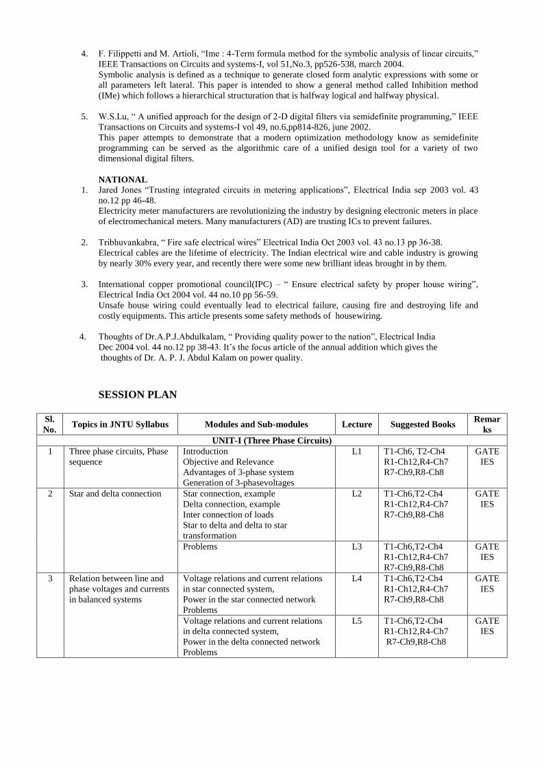
SESSION PLAN
Sl.
No. Topics in JNTU Syllabus Modules and Sub-modules Lecture Suggested Books
Remar
ks
UNIT-I (Three Phase Circuits)
1 Three phase circuits, Phase
sequence
Introduction
Objective and Relevance
Advantages of 3-phase system
Generation of 3-phasevoltages
L1 T1-Ch6, T2-Ch4
R1-Ch12,R4-Ch7
R7-Ch9,R8-Ch8
GATE
IES
2 Star and delta connection Star connection, example
Delta connection, example
Inter connection of loads
Star to delta and delta to star
transformation
L2 T1-Ch6,T2-Ch4
R1-Ch12,R4-Ch7
R7-Ch9,R8-Ch8
GATE
IES
Problems L3 T1-Ch6,T2-Ch4
R1-Ch12,R4-Ch7
R7-Ch9,R8-Ch8
GATE
IES
3 Relation between line and
phase voltages and currents
in balanced systems
Voltage relations and current relations
in star connected system,
Power in the star connected network
Problems
L4 T1-Ch6,T2-Ch4
R1-Ch12,R4-Ch7
R7-Ch9,R8-Ch8
GATE
IES
Voltage relations and current relations
in delta connected system,
Power in the delta connected network
Problems
L5 T1-Ch6,T2-Ch4
R1-Ch12,R4-Ch7
R7-Ch9,R8-Ch8
GATE
IES
Sl.
No. Topics in JNTU Syllabus Modules and Sub-modules Lecture Suggested Books
Remar
ks
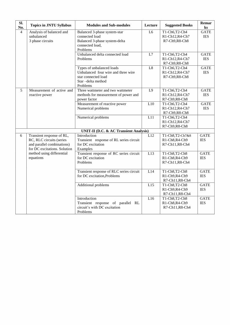
4 Analysis of balanced and
unbalanced
3 phase circuits
Balanced 3-phase system-star
connected load
Balanced 3-phase system-delta
connected load,
Problems
L6 T1-Ch6,T2-Ch4
R1-Ch12,R4-Ch7
R7-Ch9,R8-Ch8
GATE
IES
Unbalanced delta connected load
Problems
L7 T1-Ch6,T2-Ch4
R1-Ch12,R4-Ch7
R7-Ch9,R8-Ch8
GATE
IES
Types of unbalanced loads
Unbalanced four wire and three wire
star connected load
Star –delta method
Problems
L8 T1-Ch6,T2-Ch4
R1-Ch12,R4-Ch7
R7-Ch9,R8-Ch8
GATE
IES
5 Measurement of active and
reactive power
Three wattmeter and two wattmeter
methods for measurement of power and
power factor
L9 T1-Ch6,T2-Ch4
R1-Ch12,R4-Ch7
R7-Ch9,R8-Ch8
GATE
IES
Measurement of reactive power
Numerical problems
L10 T1-Ch6,T2-Ch4
R1-Ch12,R4-Ch7
R7-Ch9,R8-Ch8
GATE
IES
Numerical problems L11 T1-Ch6,T2-Ch4
R1-Ch12,R4-Ch7
R7-Ch9,R8-Ch8
UNIT-II (D.C. & AC Transient Analysis)
6
Transient response of RL,
RC, RLC circuits (series
and parallel combinations)
for DC excitations. Solution
method using differential
equations
Introduction
Transient response of RL series circuit
for DC excitation
Examples
L12 T1-Ch8,T2-Ch7&8
R1-Ch8,R4-Ch9
R7-Ch11,R8-Ch4
GATE
IES
Transient response of RC series circuit
for DC excitation
Problems
L13 T1-Ch8,T2-Ch8
R1-Ch8,R4-Ch9
R7-Ch11,R8-Ch4
GATE
IES
Transient response of RLC series circuit
for DC excitation,Problems
L14 T1-Ch8,T2-Ch8
R1-Ch9,R4-Ch9
R7-Ch11,R8-Ch4
GATE
IES
Additional problems L15 T1-Ch8,T2-Ch8
R1-Ch9,R4-Ch9
R7-Ch11,R8-Ch4
GATE
IES
Introduction
Transient response of parallel RL
circuit’s with DC excitation
Problems
L16
T1-Ch8,T2-Ch8
R1-Ch8,R4-Ch9
R7-Ch11,R8-Ch4
GATE
IES
Sl.
No. Topics in JNTU Syllabus Modules and Sub-modules Lecture Suggested Books
Remar
ks
Introduction
Transient response of parallel RC
circuit’s with DC excitation
Problems
L17 T1-Ch8,T2-Ch8
R1-Ch8,R4-Ch9
R7-Ch11,R8-Ch4
GATE
IES
response of parallel RLC circuit’s
Transient with DC excitation
Problems
L18 T1-Ch8,T2-Ch8
R1-Ch9,R4-Ch9
R7-Ch11,R8-Ch4
GATE
IES
7 Solution method using
Laplace transform methods
Applications of Laplace transform for
RL circuits
L19 T1-Ch8,T2-Ch8
R7-Ch11
R8-Ch4
GATE
IES
Applications of Laplace transform RC
circuits
L20 T1-Ch8,T2-Ch8
R7-Ch11
R8-Ch4
GATE
IES
Applications of Laplace transform RLC
circuits
L21 T1-Ch8,T2-Ch8
R7-Ch11
R8-Ch4
GATE
IES
Problems on series circuits using
Laplace transform
L22 T1-Ch8,T2-Ch8
R7-Ch11
R8-Ch4
GATE
IES
8 Transient response of RL,
RC, RLC circuits (series
and parallel combinations)
for sinusoidal excitation.
Solution method using
differential equations
Transient response of RL series circuit
for sinusoidal excitation
Problems
L23 T1-Ch8,T2-Ch8
R7-Ch11
R8-Ch4
GATE
IES
Transient response of RC series circuit
for sinusoidal excitation
Problems
L24 T1-Ch8,T2-Ch8
R7-Ch11
R8-Ch4
GATE
IES
Introduction
Transient response of RLC series circuit
for sinusoidal excitation
Problems
L25 T1-Ch8,T2-Ch8
R7-Ch11
R8-Ch4
GATE
IES
Additional problems L26 T1-Ch8,T2-Ch8
R7-Ch11
R8-Ch4
GATE
IES
Introduction
Transient response of parallel RL
circuit’s with sinusoidal excitation
Problems
L27 T1-Ch8,T2-Ch8
R7-Ch11
R8-Ch4
GATE
IES
Transient response of parallel RC
circuit’s with sinusoidal excitation
Problems
L28 T1-Ch8,T2-Ch8
R7-Ch11
R8-Ch4
GATE
IES
Transient response of parallel RLC
circuits with sinusoidal excitation
Problems
L29 T1-Ch8,T2-Ch8
R7-Ch11
R8-Ch4
GATE
IES
9 Solution method using
Laplace transform methods
Applications of Laplace transform for
RL circuits
L30 T1-Ch8,T2-Ch8
R7-Ch11
R8-Ch4
GATE
IES
Applications of Laplace transform RC
circuits
L31 T1-Ch8,T2-Ch8
R7-Ch11
R8-Ch4
GATE
IES
Applications of Laplace transform RLC
circuits
L32 T1-Ch8,T2-Ch8
R7-Ch11
R8-Ch4
GATE
IES
Problems on series circuits using
Laplace transform
L33 T1-Ch8,T2-Ch8
R7-Ch11,R8-Ch4
GATE
IES
Sl.
No. Topics in JNTU Syllabus Modules and Sub-modules Lecture Suggested Books
Remar
ks
UNIT-III ( Network Functions )
10 The concept of complex
frequency, Physical
interpretation of complex
frequency
Physical significance of complex
frequency and a number of special
cases for values of Sn
L34 T1-Ch14,R4-Ch10
R7-Ch15,R8-Ch11
R9-Ch9,R10-h9
GATE
IES
11 Transform impedance
andtransform circuits
Transform Impedance and Transform
admittance representation for R,L and C
elements
L35 T1-Ch14,R4-Ch10
R7-Ch15,R8-Ch11
R9-Ch9,R10-Ch9
GATE
IES
12 Series and parallel
combination of elements,
terminal pairs or ports
Representation of network in series and
parallel combinations,problems
L36 T1-Ch14,R4-Ch10
R7-Ch15,R8-Ch11
R10-Ch9,
R9-Ch9&10
GATE
IES
13 Networks functions for
the one-port and two-port
Voltage transfer ratio
Current transfer ratio
Transfer impedance and admittance
Problems
L37 T1-Ch14,R4-Ch10
R7-Ch15,R8-Ch11
R9-Ch10,R10-Ch9
GATE
IES
14 Poles and zeros of network
functions, Significance of
poles and zeros
Driving point impedance and
admittance
Voltage transform ratio
Other network functions
L38 T1-Ch14,R4-Ch10
R7-Ch15,R8-Ch11
R9-Ch10,R10-Ch9
GATE
IES
15 Properties of
driving point functions,
Properties of transfer
functions
Definition
Poles and zeros
T and π equivalent networks
L39 T1-Ch14,R4-Ch10
R7-Ch15,R8-Ch11
R9-Ch10,R10-Ch9
GATE
IES
16 Necessary conditions for
driving point functions,
Necessary conditions for
transfer functions
The restrictions on pole and zero
location in driving point and transfer
functions
L40 T1-Ch14,R4-Ch10
R7-Ch15,R8-Ch11
R9-Ch10,R10-Ch9
GATE
IES
17 Time domain response from
pole zero plot
Current response for a given voltage
Problems
L41 T1-Ch14,R4-Ch10
R7-Ch15,R8-Ch11
R9-Ch10,R10-Ch9
GATE
IES
UNIT-IV ( Network Parameters)
18 Two port network
parameters – z, y, ABCD
and hybrid parameters and
their relations
Two port network
Explanation to z - parameters
Problems
L42 T1-Ch12,T2-Ch9
R1-Ch17,R4-Ch14
R7-Ch16,R8-Ch10
R9-Ch11
GATE
IES
Explanation to y - parameters
Problems
L43 T1-Ch12,T2-Ch9
R1-Ch17,R4-Ch14
R7-Ch16,R8-Ch10
R9-Ch11
GATE
IES
Explanation to T – parameters
(A, B, C, D parameters)
Cascade connection
Problems
L44 T1-Ch12,T2-Ch9
R1-Ch17,R4-Ch14
R7-Ch16,R8-Ch10
R9-Ch11
GATE
IES
Explanation to h - parameters
Problems
L45 T1-Ch12,T2-Ch9
R1-Ch17,R4-Ch14
R7-Ch16,R8-Ch10
R9-Ch11
GATE
IES
Expression of z-parameters interms of
y-parameters and vice-versa
ABCD parameters interms of z-
parameters and y-parameters
L46 T1-Ch12, T2-Ch9
R1-Ch17,R4-Ch14
R7-Ch16,R8-Ch10
R9-Ch11
GATE
IES
Reciprocity and symmetricity
conditions
Problems
L47 T1-Ch12, T2-Ch9
R7-Ch16,R8-Ch10
R9-Ch11
GATE
IES
Problems L48 T1-Ch12, T2-Ch9
R1-Ch17,R4-Ch14
R7-Ch16,R8-Ch10
R9-Ch11
GATE
IES
Sl.
No. Topics in JNTU Syllabus Modules and Sub-modules Lecture Suggested Books
Remar
ks
19 Cascaded networks Series and parallel combination of two
port network, Problems
L49 T1-Ch12, T2-Ch9
R1-Ch17,R4-Ch14
R7-Ch16,R8-Ch10
R9-Ch11
GATE
IES
Expression for network parameters
connected in cascade
L50 T1-Ch12, T2-Ch9
R1-Ch17,R4-Ch14
R7-Ch16,R8-Ch10
GATE
IES
Expression for network parameters
connected in cascade
L51 T1-Ch12, T2-Ch9
R1-Ch17,R4-Ch14
R7-Ch16,R8-Ch10
GATE
IES
20 Concept of transformed
network,
Two port network
parameters using
transformed variables
Resistance ,Inductance and Capacitance
Voltage and current transfer ratios
Transfer impedance and admittance
L52 T1-Ch12, T2-Ch9
R1-Ch17,R4-Ch14
R7-Ch16,R8-Ch10
GATE
IES
Numerical problems on two port
networks
L53 T1-Ch12, T2-Ch9
R1-Ch17,R4-Ch14
R7-Ch16,R8-Ch10
GATE
IES
Numerical problems on two port
networks
L54 T1-Ch12, T2-Ch9
R1-Ch17,R4-Ch14
R7-Ch16,R8-Ch10
R9-Ch11
GATE
IES
Numerical problems on two port
networks
L55 T1-Ch12, T2-Ch9
R1-Ch17,R4-Ch14
R7-Ch16,R8-Ch10
R9-Ch11
GATE
IES
UNIT-V (Filters and Fourier analysis of AC Circuits)
21 Low pass, High pass, Band
pass, Band elimination,
Prototype filter design
Introduction to filters
Properties
Classification
Equation of filter networks
L56 T1-Ch18,T2-Ch10
R7-Ch17,R10-Ch10
GATE
IES
Concept of working of low pass and
high pass filters using reactive elements
Analysis of prototype filter section
L57 T1-Ch18, T2-Ch10
R7-Ch17,R10-Ch10
GATE
IES
Analysis and design of prototype low
pass filter (constant-k)
L58 T1-Ch18, T2-Ch10
R7-Ch17,R10-Ch10
GATE
IES
Analysis and design of prototype high
pass filter (constant-k)
L59 T1-Ch18, T2-Ch10
R7-Ch17,R10-Ch10
GATE
IES
Problems on low pass and high pass
filters
L60 T1-Ch18, T2-Ch10
R7-Ch17,R10-Ch10
GATE
IES
m-derived low pass and High pass filter
problems
L61 T1-Ch18, T2-Ch10
R7-Ch17,R10-Ch10
Analysis and design of prototype band
pass filter (constant-k)
L62 T1-Ch18, T2-Ch10
R7-Ch17,R10-Ch10
GATE
IES
Analysis and design of prototype band
stop filter (constant-k)
L63 T1-Ch18, T2-Ch10
R7-Ch17,R10-Ch10
GATE
IES
Problems on band pass and band stop
filters
L64 T1-Ch18, T2-Ch10
R7-Ch17,R10-Ch10
GATE
IES
22 The Fourier theorem,
Consideration of symmetry
Introduction to Fourier theorem
Symmetry in Fourier series
Even, odd and half wave symmetry
Problems
L65 T1-Ch16, R1-Ch18
R7-Ch12,R8-Ch7
R9-Ch15
GATE
IES
23 Exponential form of Fourier
series
Representation of periodic function
Problems
L66 T1-Ch16, R1-Ch18
R7-Ch12, R8-Ch7
R9-Ch15
GATE
IES
24 Line spectra and phase
anglespectra, Fourier
integrals and fourier
transforms
Problems on fourier transforms for
various inputs
L67 T1-Ch16, R1-Ch18
R7-Ch12, R8-Ch7
R9-Ch16
GATE
IES
Fourier transform of periodic signals
and problems
L68 T1-Ch16, R1-Ch18
R7-Ch12, R8-Ch7
GATE
IES
Sl.
No. Topics in JNTU Syllabus Modules and Sub-modules Lecture Suggested Books
Remar
ks
R9-Ch16
25 Properties of fourier
transforms
Linearity, Scaling, Symmetry,
Convolution, Frequency differentiation
and Integration, Time shifting and
frequency shifting
L69 T1-Ch16, R1-Ch18
R7-Ch12, R8-Ch7
R9-Ch16
GATE
IES
Problems L70 T1-Ch16, R1-Ch18
R7-Ch12, R8-Ch7
R9-Ch16
GATE
IES
UNIT-I 1. a) Derive the relation between line and phase currents and Voltages in star connection of a 3- Phase
( balanced and unbalanced ) system.
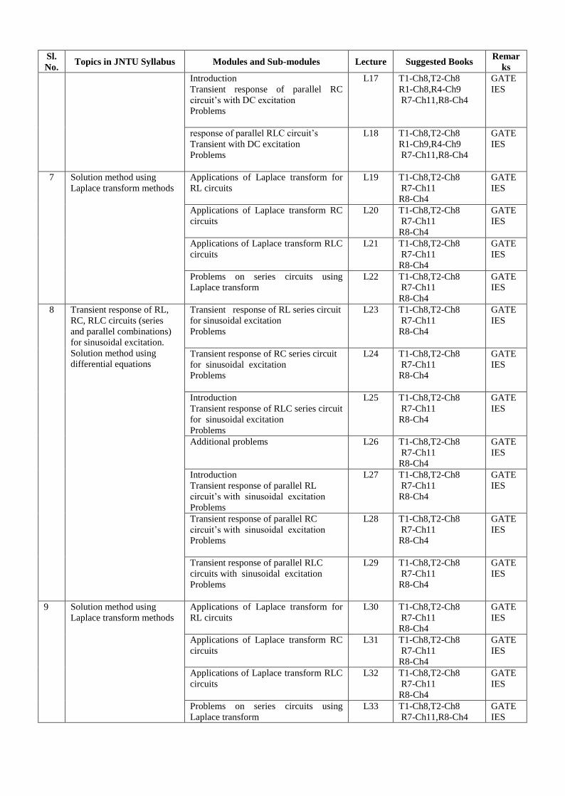
b) A delta connected load is shown in Figure1. When each phase has an impedance of (10+j15) Ω what
is the line current if the applied line current if the applied line voltage is 230V? Obtain the amount
of power consumed per phase. What is the phasor sum of the three line currents? [Jun-2014]
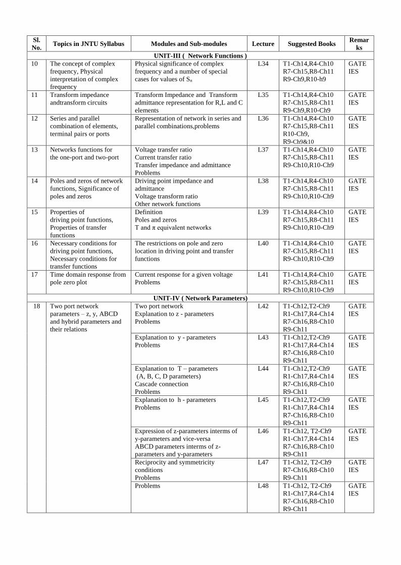
2. a) Give Star – Delta and Delta – Star transformation equations.
b) Obtain star connected equivalent circuit for the delta connected circuit shown in
the below Figure 1.
c) A three phase balanced delta connected load of (4+j8)Ω is connected across a
400V, 3-Ø balanced supply. Determine the phase currents and line currents.
Assume the phase of sequence to be RYB. Also calculate the power drawn by
load. [May-2013]
3. a) Discuss relationship between line and phase quantities in star and delta connected systems.
b) A 400 V, 3-Ø balanced source is connected to an unbalanced mesh connected impedances of
Zab=10450, Zbc=20200, Zca=30-530. Determine the line currents and the total active & reactive
power. [April-May, 2012]
4. a) Derive the expressions for power using two wattmeter method.
b) Discuss about the readings of wattmeters in two wattmeter method due to effect of power factor.
[April-May, 2012]
5. a) Draw the phasor diagram for a 3-Ø motor whose power is measured by two wattmeter method.
[April-May, 2012]
b) Derive the expression for the instantaneous power measured in the above case.
6. a) Explain the methods to determine active and reactive power in a 3-Ø circuit.
b) A star connected load of ZR
= 6Ω, ZY
= j5Ω, ZB
= j7Ω is supplied by a 400V, 3-Ø symmetrical
supply. Determine the line currents. The phase sequence is RYB.
[April-May, 2012]
7. a) Derive the relation between line and phase voltages and currents in a balanced delta
Connected system.
b) A balanced three phase load of 25+j30Ω per phase is connected in delta across 440V, 3 phase
Supply. Determine line currents, phase currents & Total active power. Also draw the phasor diagram.
[Dec-2011]
8. a) What are the different methods used for measuring power in three phase circuits?
b) A balanced the phase load of 30+j40Ω per phase is star connected across 400 V, 50 Hz,
3-phase supply. Determine phase currents and phase voltages. Also draw the phasor diagram.
[Dec-2011]
9. a) With the help of circuit diagram, explain the procedure of measuring power in three phase
circuits using two watt meters.
b) A balanced three load of (15-j20)Ω per phase is delta connected across 220V, 50Hz, 3-phase
supply. Calculate total active and reactive power. Also draw the complete phasor diagram.
[Dec-2011]
10. a) Derive the relationship between line and phase voltage and currents in a balanced star
connected system. [Dec-2011]
b) Prove that the power in three phase circuit can be measured using two watt meters.
11. a) Derive the expression for the power measured and power factor in the two watt meter method
applied for balanced loads.
b) A 3-phase 500 V motor operates at a power factor of 0.4 and takes an input power of 30 kW.
Two watt meters are employed to measure the input power. Find readings on each instrument.
[Apr/May, 2011]
12. a) Derive expression for the power measured in two watt meter method for un balanced loads.
b) The two watt meter readings in a 3 - phase power measurement are 800 W and 400 W.
The latter reading is being obtained after the reversal of current coil. Calculate the total power
and power factor of the load. [Apr/May, 2011]
13. a) Discuss the effect of variation of power factor on the readings of two watt meters used in
3-phase power measurement. [Apr/May, 2011]
b) Calculate the active and reactive components of the currents in each phase of a star
connected generator supplying at 11 kV to a load of 5 MW at 0.8 pf lagging. What is the
value of new output if the total current is same and the pf is raised to 0.85?
14. a) Explain the measurement of reactive power in a 3-phase circuit single wattmeter method.
b) A balanced 3-phase star connected load of 200 kW takes a leading current of 150 amps with
a line voltage of 1200 V at 60 Hz. What are the circuit constants of the load per phase?
[Apr/May, 2011]
15.. i. Three identical impedances of (3+j4)ohms are connected in delta. Find an equivalent star network such
that the line current is the same when connected to the same supply.
ii. Three impedances of (7+j4)ohms, (3+j2)ohms and (9+j2)ohms are connected between neutral and the
R, Y and B phases. The line voltage is 440V, Calculate.
a. The line currents and
b. The current in the neutral wire.
c. Find the power consumed in each phase and the total power drawn by the circuit. (May 08)
16. i. Explain how power is measured in three phase delta connected load using two wattmeters.
ii. A balanced mesh connected load of (8+j6)ohms per phase is connected to a 3-phase, 50Hz, 230V
supply. Calculate
a. line current
b. Power factor
c. Reactive volt-ampere and
d. Total volt-ampere (May 08)
17. A symmetrical 3-phase, 3-wire, 440V supply is connected to a star connected load. The impedances in each
branch are : Z1=(2+j3)ohms, Z2=(1-j2)ohms, Z3=(3+j4)ohms. Find its equivalent delta connected load.
Hence find the phase and line currents and the total power consumed in the circuits. (May 08)
18. i. The power delivered to a balanced delta connected load by a 400 volt 3-phase supply is measured by
two wattmeter method. If the readings of the two wattmeter are 2000 and ? 1500 watts respectively,
calculate the magnitude of the impedance in each arm of the delta load and its resistive component?
ii. A balanced delta connected load of (2+j3) ohms per phase is connected to a balanced three-phase 440V
supply. The phase current is 10A. Find the
a. total active power
b. Reactive power and
c. apparent power in the circuit (Feb 08)
19. i. On a symmetrical 3-phase system, phase sequence RYB, a capacitive reactance of 8ohms is across YB
and a coil (R+jX) cross RY. Find R and X such that Iy = 0.
ii. Find the reading on the wattmeter when the network shown in figure. is connected to a symmetrical
440V, 3-phase supply. The phase sequence is RYB. (Feb 08, Sep 06)
20. i. What is phase sequence? Explain its significance.
ii. A star connected three phase load has a resistance of 8 ohms and a capacitive reactance of 10 ohms in
each phase. It is fed from a 400v, 3-phase balanced supply.
a. Find the line current, total volt-amperes, active and reactive power
b. Draw phasor diagram showing phase voltages, line voltages and currents. (Feb 08)
21. i. For the network shown in figure , calculate the line currents and power consumed if the phase sequence
is ABC.
ii. An unbalanced star connected load is connected across a 3-
RYB as shown in figurea. Two wattmeters are connected to measure the total power supplied as shown in
fig. Find the readings of the wattmeters. (May 07)
22. i. Two wattmeters are used to measure power in a 3-phase three wire load. Determine the total power,
power factor and reactive power, if the two watt meters read
a. 1000w each, both positive
b. 1000w each, but of opposite sign.
ii. What is phase sequence? Explain its significance?
iii. What are the advantages of a poly phase system over a single phase system. (May 07)
23. i. The power delivered to a balanced delta connected load by a 400 volt 3-phase supply is measured by
two wattmeter method. If the readings of the two wattmeter are 2000 and 1500 watts respectively, calculate
the magnitude of the impedance in each arm of the delta load and its resistive component?
ii. A balanced delta connected load of (2+j3) Ωper phase is connected to a balanced three-phase 440V
supply. The phase current is 10A. Find the
a. total active power
b. Reactive power and
c. apparent power in the circuit. (May 07)
24. i. A balanced 3-ph star connected load of 150 Kw takes a leading current of 100A with a line voltage of
1100 V, 50Hz. Find the circuit constants of the load per phase?
ii. Three equal star connected inductors takes 8Kw at P.f of 0.8 when connected to 460V, 3-
supply. Find the line currents, if one conductor is short circuited. (Sep 06)
25. i. Determine the line currents in an unbalanced star connect load supplied from a symmetrical 3-phase
440v system. The branch impedances The phase sequence is RYB. (Sep 06)
26. i. Three impedances each of (3-j4)ohm is connected in delta connection across a 3-phase, 230V
balanced supply. Calculate the line and phase currents in the delta connected load and the power delivered
to the load?
ii. In power measurement of 3-phaseload connected by 3-phase supply by two wattmeter method, prove
the following for leading power factor loads.
(May 06)
27. i. Three identical resistances are connected in a star fashion against a balanced three phase voltage
supply. If one of the resistance is removed, how much power is to be reduced?
ii. A 3-phase load has a resistance of 10ohm in each phase and is connected in
a. star and
b. delta against a 400V, 3-phase supply. Compare the power consumed in both the cases.
iii. What is the difference between RYB phase sequence with RBY phase sequence? (May 06)
28. i. Two resistors each of 100ohm are connected in series. The phases a and c of a three phase 400V supply
are connected to the two ends and phase b is connected to the junction of the two resistors. Find the line
currents.
ii. Derive the expressions for wattmeter readings in two wattmeter method with balanced star connected
load. How do you calculate the power factor of the balanced load from wattmeter readings? (May 06)
UNIT-II
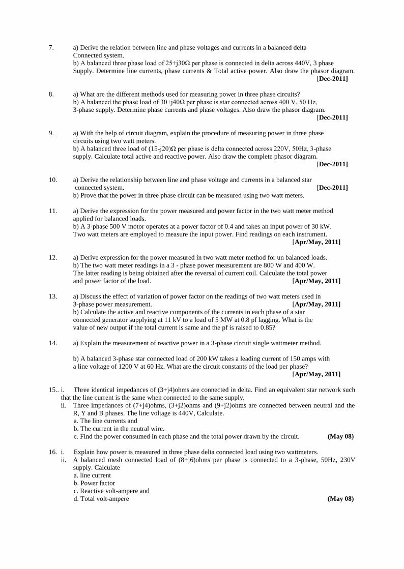
1. a) Explain the transient analysis of series R-C circuit having D.C. excitation ( first order circuit).
b) A circuit shown in figure 2 the switch K is Kept first at position 1 and steady state condition is
reached. Is reached At t = 0 the switch is moved to position 2. Find the current value in both the
cases. [Jun-2014]
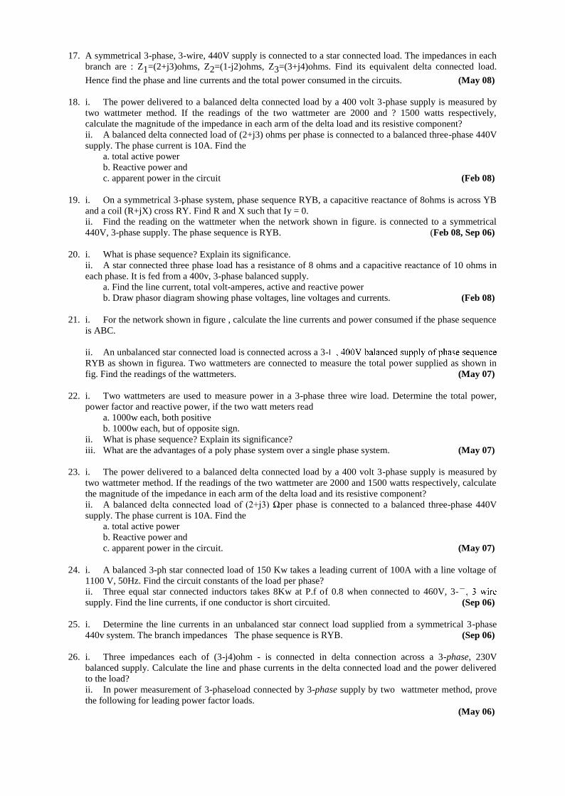
2. a) Explain the transient analysis of series R-L circuit with sinusoidal excitation ( first order circuit ).
b) In the figure 3 shown below a parallel RLC, circuit consisting of R= 0.2 Ω L= 0.6 H and C= 2F.
Capacitor Chas an initial voltage of 15V ( polarity is shown in the figure). The switch K is closed at
t= 0. Obtain the value of v (t) [Jun-2014]
3. a) Define Bandwidth and Quality factor.
b) A voltage v(t) = 10 Sinωt is applied to a series RLC circuit. At the resonant frequency
of the circuit, the maximum voltage across the capacitor is found to be 500V.Moreover the
bandwidth is known to be 400rad/sec and the impedance at resonance is 100Ω. Find the
resonant frequency, also find the values of L and C of the circuit. [May-2013]
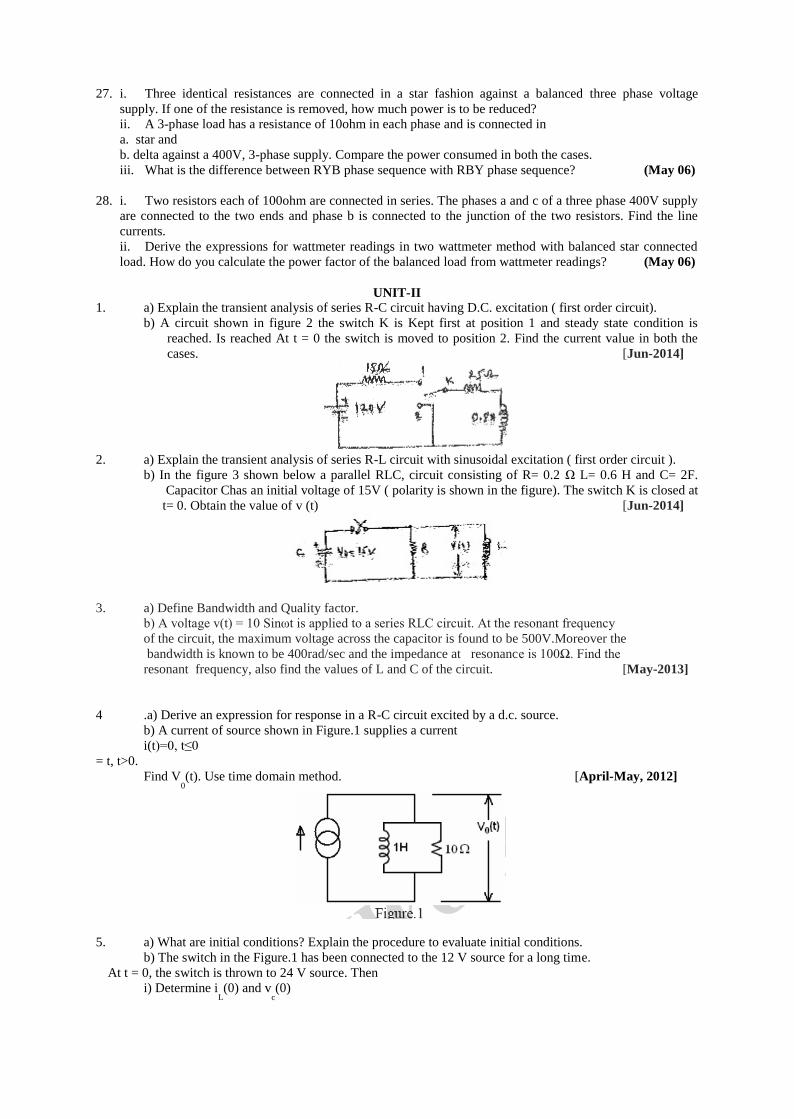
4 .a) Derive an expression for response in a R-C circuit excited by a d.c. source.
b) A current of source shown in Figure.1 supplies a current
i(t)=0, t≤0
= t, t>0.
Find V0(t). Use time domain method. [April-May, 2012]
5. a) What are initial conditions? Explain the procedure to evaluate initial conditions.
b) The switch in the Figure.1 has been connected to the 12 V source for a long time.
At t = 0, the switch is thrown to 24 V source. Then
i) Determine iL(0) and v
c(0)

ii) Write the differential equation governing vc(t) for t>0
iii) Compute the steady state value of vc(t). [April-May, 2012]
Figure.1
6. a) Derive an expression for response of R-L-C series circuit excited by a D.C. excitation.
b) In the circuit shown in the Figure.1 below, the voltage across the circuit is eg(t) = 2.5 t volts.
What are the values of i(t) and VL(t) at 4s? [April-May, 2012]
Figure.1
7. a) Derive the expression for the response in a R-L circuit for D.C. excitation. Define time constant.
b) For the circuit given in Figure.1, steady state conditions are reached for the switch K in
position ‘1’. At t = 0, the switch is changed to position 2. Use the time domain method to
determine the current through the inductor for all t≥0+ [April-May,
2012]
Figure.1
8. a) Derive an expression for response in a R-L series circuit for a sinusoidal excitation.
Use Laplace transform approach. [April-May,
2012]
b) For the circuit given below in Figure.2, the applied voltage is V(t) = 10 Sin(200t+600
).
Find the current through the circuit for t≥0. Assume zero initial condition. Use time domain approach.
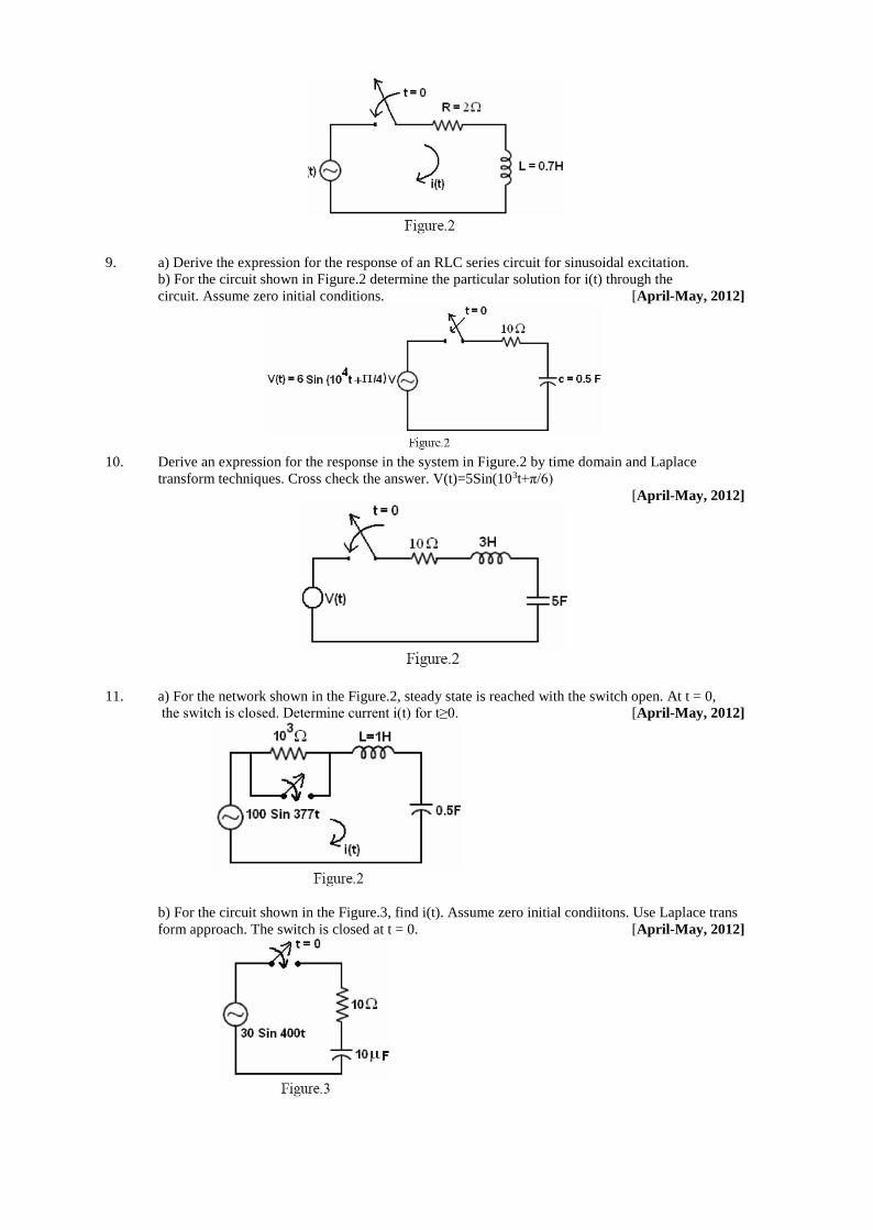
9. a) Derive the expression for the response of an RLC series circuit for sinusoidal excitation.
b) For the circuit shown in Figure.2 determine the particular solution for i(t) through the
circuit. Assume zero initial conditions. [April-May, 2012]
10. Derive an expression for the response in the system in Figure.2 by time domain and Laplace
transform techniques. Cross check the answer. V(t)=5Sin(103t+π/6)
[April-May, 2012]
11. a) For the network shown in the Figure.2, steady state is reached with the switch open. At t = 0,
the switch is closed. Determine current i(t) for t≥0. [April-May, 2012]
b) For the circuit shown in the Figure.3, find i(t). Assume zero initial condiitons. Use Laplace trans
form approach. The switch is closed at t = 0. [April-May, 2012]
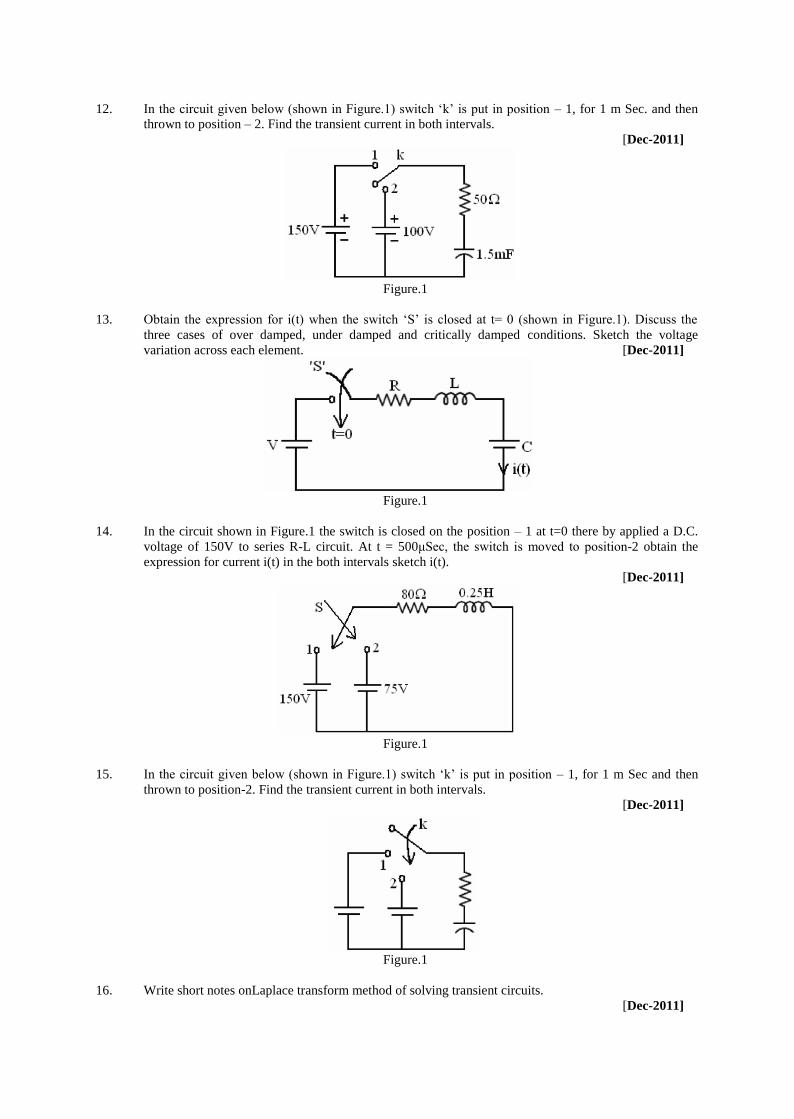
12. In the circuit given below (shown in Figure.1) switch ‘k’ is put in position – 1, for 1 m Sec. and then
thrown to position – 2. Find the transient current in both intervals.
[Dec-2011]
Figure.1
13. Obtain the expression for i(t) when the switch ‘S’ is closed at t= 0 (shown in Figure.1). Discuss the
three cases of over damped, under damped and critically damped conditions. Sketch the voltage
variation across each element. [Dec-2011]
Figure.1
14. In the circuit shown in Figure.1 the switch is closed on the position – 1 at t=0 there by applied a D.C.
voltage of 150V to series R-L circuit. At t = 500μSec, the switch is moved to position-2 obtain the
expression for current i(t) in the both intervals sketch i(t).
[Dec-2011]
Figure.1
15. In the circuit given below (shown in Figure.1) switch ‘k’ is put in position – 1, for 1 m Sec and then
thrown to position-2. Find the transient current in both intervals.
[Dec-2011]
Figure.1
16. Write short notes onLaplace transform method of solving transient circuits.
[Dec-2011]
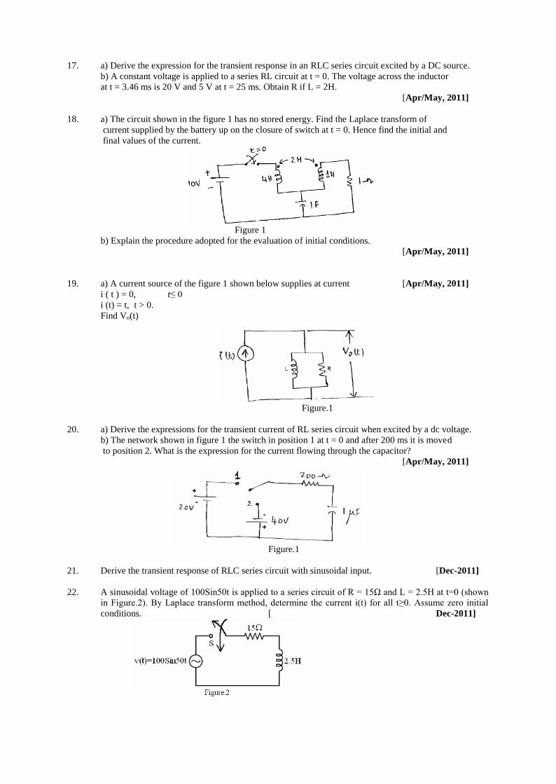
17. a) Derive the expression for the transient response in an RLC series circuit excited by a DC source.
b) A constant voltage is applied to a series RL circuit at t = 0. The voltage across the inductor
at t = 3.46 ms is 20 V and 5 V at t = 25 ms. Obtain R if L = 2H.
[Apr/May, 2011]
18. a) The circuit shown in the figure 1 has no stored energy. Find the Laplace transform of
current supplied by the battery up on the closure of switch at t = 0. Hence find the initial and
final values of the current.
Figure 1
b) Explain the procedure adopted for the evaluation of initial conditions.
[Apr/May, 2011]
19. a) A current source of the figure 1 shown below supplies at current [Apr/May, 2011]
i ( t ) = 0, t≤ 0
i (t) = t, t > 0.
Find Vo(t)
Figure.1
20. a) Derive the expressions for the transient current of RL series circuit when excited by a dc voltage.
b) The network shown in figure 1 the switch in position 1 at t = 0 and after 200 ms it is moved
to position 2. What is the expression for the current flowing through the capacitor?
[Apr/May, 2011]
Figure.1
21. Derive the transient response of RLC series circuit with sinusoidal input. [Dec-2011]
22. A sinusoidal voltage of 100Sin50t is applied to a series circuit of R = 15Ω and L = 2.5H at t=0 (shown
in Figure.2). By Laplace transform method, determine the current i(t) for all t≥0. Assume zero initial
conditions. [ Dec-2011]
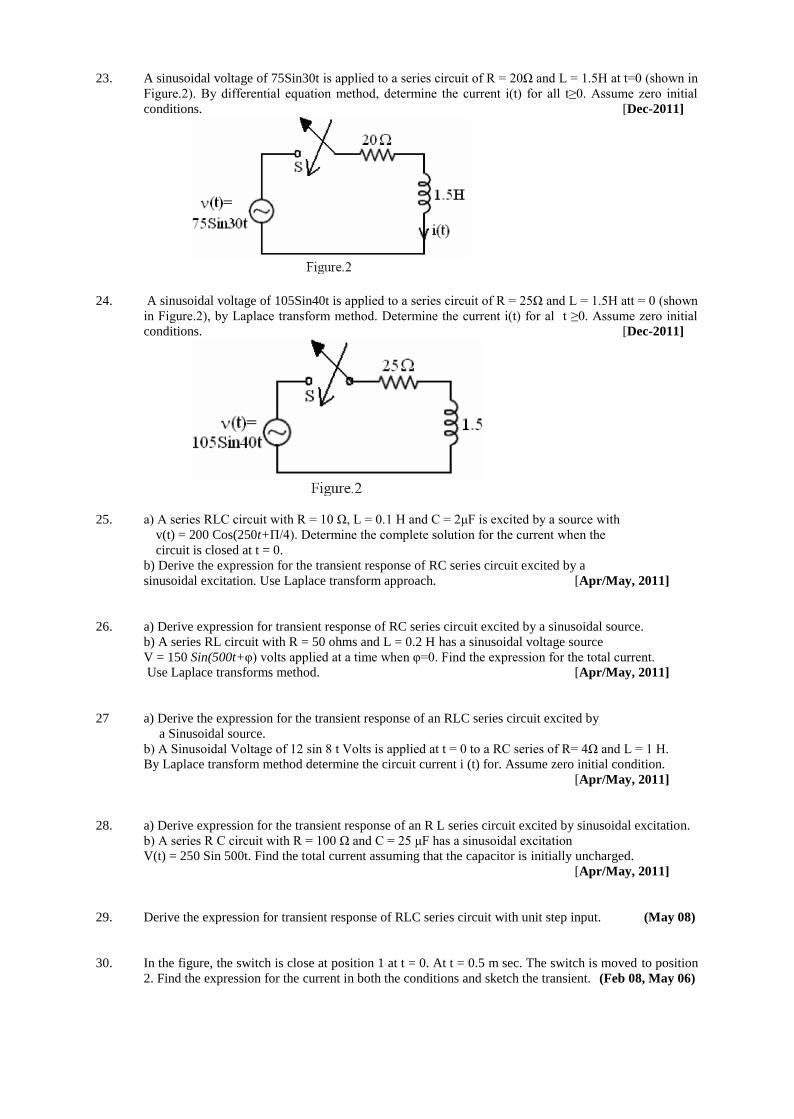
23. A sinusoidal voltage of 75Sin30t is applied to a series circuit of R = 20Ω and L = 1.5H at t=0 (shown in
Figure.2). By differential equation method, determine the current i(t) for all t≥0. Assume zero initial
conditions. [Dec-2011]
24. A sinusoidal voltage of 105Sin40t is applied to a series circuit of R = 25Ω and L = 1.5H att = 0 (shown
in Figure.2), by Laplace transform method. Determine the current i(t) for al t ≥0. Assume zero initial
conditions. [Dec-2011]
25. a) A series RLC circuit with R = 10 Ω, L = 0.1 H and C = 2μF is excited by a source with
v(t) = 200 Cos(250t+Π/4). Determine the complete solution for the current when the
circuit is closed at t = 0.
b) Derive the expression for the transient response of RC series circuit excited by a
sinusoidal excitation. Use Laplace transform approach. [Apr/May, 2011]
26. a) Derive expression for transient response of RC series circuit excited by a sinusoidal source.
b) A series RL circuit with R = 50 ohms and L = 0.2 H has a sinusoidal voltage source
V = 150 Sin(500t+φ) volts applied at a time when φ=0. Find the expression for the total current.
Use Laplace transforms method. [Apr/May, 2011]
27 a) Derive the expression for the transient response of an RLC series circuit excited by
a Sinusoidal source.
b) A Sinusoidal Voltage of 12 sin 8 t Volts is applied at t = 0 to a RC series of R= 4Ω and L = 1 H.
By Laplace transform method determine the circuit current i (t) for. Assume zero initial condition.
[Apr/May, 2011]
28. a) Derive expression for the transient response of an R L series circuit excited by sinusoidal excitation.
b) A series R C circuit with R = 100 Ω and C = 25 μF has a sinusoidal excitation
V(t) = 250 Sin 500t. Find the total current assuming that the capacitor is initially uncharged.
[Apr/May, 2011]
29. Derive the expression for transient response of RLC series circuit with unit step input. (May 08)
30. In the figure, the switch is close at position 1 at t = 0. At t = 0.5 m sec. The switch is moved to position
2. Find the expression for the current in both the conditions and sketch the transient. (Feb 08, May 06)
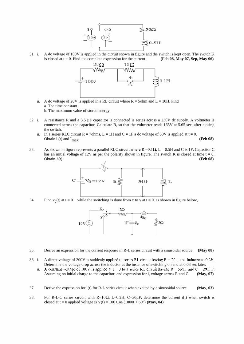
31. i. A dc voltage of 100V is applied in the circuit shown in figure and the switch is kept open. The switch K
is closed at t = 0. Find the complete expression for the current. (Feb 08, May 07, Sep, May 06)
ii. A dc voltage of 20V is applied in a RL circuit where R = 5ohm and L = 10H. Find
a. The time constant
b. The maximum value of stored energy.
32. i. A resistance R and a 3.5 µF capacitor is connected is series across a 230V dc supply. A voltmeter is
connected across the capacitor. Calculate R, so that the voltmeter reads 165V at 5.65 sec. after closing
the switch.
ii. In a series RLC circuit R = 7ohms, L = 1H and C = 1F a dc voltage of 50V is applied at t = 0.
Obtain i (t) and Imax. (Feb 08)
33. As shown in figure represents a parallel RLC circuit where R =0.1Ω, L = 0.5H and C is 1F. Capacitor C
has an initial voltage of 12V as per the polarity shown in figure. The switch K is closed at time t = 0.
Obtain .i(t). (Feb 08)
34. Find vc(t) at t = 0 + while the switching is done from x to y at t = 0. as shown in figure below,
35. Derive an expression for the current response in R-L series circuit with a sinusoidal source. (May 08)
36. i. A direct voltage of 200V is suddenly
Determine the voltage drop across the inductor at the instance of switching on and at 0.03 sec later.
ii.
Assuming no initial charge to the capacitor, and expression for i, voltage across R and C. (May, 07)
37. Derive the expression for i(t) for R-L series circuit when excited by a sinusoidal source. (May, 03)
38. For R-L-C series circuit with R=10Ω, L=0.2H, C=50μF, determine the current i(t) when switch is
closed at t = 0 applied voltage is V(t) = 100 Cos (1000t + 60°) (May, 04)
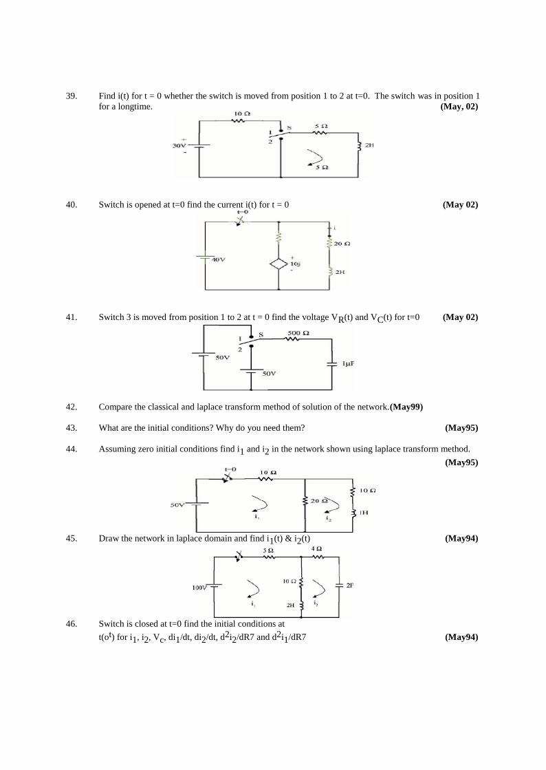
39. Find i(t) for t = 0 whether the switch is moved from position 1 to 2 at t=0. The switch was in position 1
for a longtime. (May, 02)
40. Switch is opened at t=0 find the current i(t) for t = 0 (May 02)
41. Switch 3 is moved from position 1 to 2 at t = 0 find the voltage VR(t) and VC(t) for t=0 (May 02)
42. Compare the classical and laplace transform method of solution of the network.(May99)
43. What are the initial conditions? Why do you need them? (May95)
44. Assuming zero initial conditions find i1 and i2 in the network shown using laplace transform method.
(May95)
45. Draw the network in laplace domain and find i1(t) & i2(t) (May94)
46. Switch is closed at t=0 find the initial conditions at
t(ot) for i1, i2, Vc, di1/dt, di2/dt, d2i2/dR7 and d2i1/dR7 (May94)
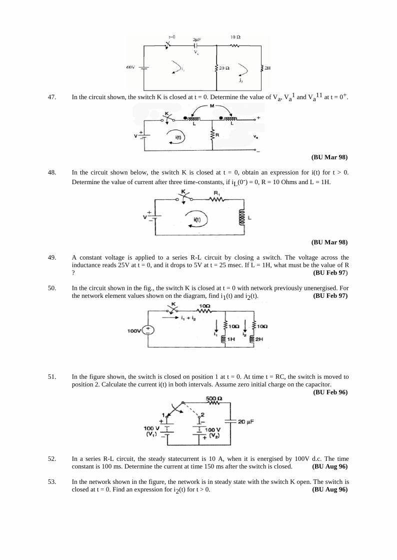
47. In the circuit shown, the switch K is closed at t = 0. Determine the value of Va, Va1 and Va
11 at t = 0+.
(BU Mar 98)
48. In the circuit shown below, the switch K is closed at t = 0, obtain an expression for i(t) for t > 0.
Determine the value of current after three time-constants, if iL(0-) = 0, R = 10 Ohms and L = 1H.
(BU Mar 98)
49. A constant voltage is applied to a series R-L circuit by closing a switch. The voltage across the
inductance reads 25V at t = 0, and it drops to 5V at t = 25 msec. If L = 1H, what must be the value of R
? (BU Feb 97)
50. In the circuit shown in the fig., the switch K is closed at t = 0 with network previously unenergised. For
the network element values shown on the diagram, find i1(t) and i2(t). (BU Feb 97)
51. In the figure shown, the switch is closed on position 1 at t = 0. At time t = RC, the switch is moved to
position 2. Calculate the current i(t) in both intervals. Assume zero initial charge on the capacitor.
(BU Feb 96)
52. In a series R-L circuit, the steady statecurrent is 10 A, when it is energised by 100V d.c. The time
constant is 100 ms. Determine the current at time 150 ms after the switch is closed. (BU Aug 96)
53. In the network shown in the figure, the network is in steady state with the switch K open. The switch is
closed at t = 0. Find an expression for i2(t) for t > 0. (BU Aug 96)
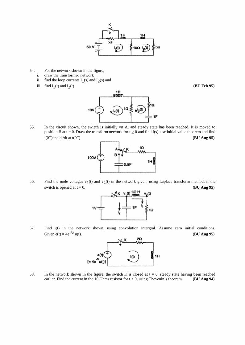
54. For the network shown in the figure,
i. draw the transformed network
ii. find the loop currents I1(s) and I2(s) and
iii. find i1(t) and i2(t) (BU Feb 95)
55. In the circuit shown, the switch is initially on A, and steady state has been reached. It is moved to
position B at t = 0. Draw the transform network for t > 0 and find I(s). use initial value theorem and find
i(0+)and di/dt at t(0+). (BU Aug 95)
56. Find the node voltages v1(t) and v2(t) in the network given, using Laplace transform method, if the
switch is opened at t = 0. (BU Aug 95)
57. Find i(t) in the network shown, using convolution intergral. Assume zero initial conditions.
Given e(t) = 4e-3t u(t). (BU Aug 95)
58. In the network shown in the figure, the switch K is closed at t = 0, steady state having been reached
earlier. Find the current in the 10 Ohms resistor for t > 0, using Thevenin’s theorem. (BU Aug 94)
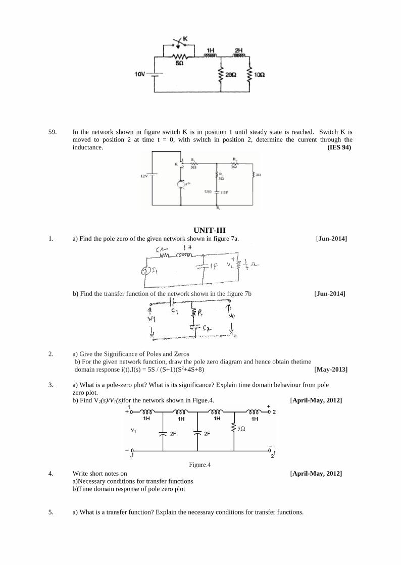
59. In the network shown in figure switch K is in position 1 until steady state is reached. Switch K is
moved to position 2 at time t = 0, with switch in position 2, determine the current through the
inductance. (IES 94)
UNIT-III 1. a) Find the pole zero of the given network shown in figure 7a. [Jun-2014]
b) Find the transfer function of the network shown in the figure 7b [Jun-2014]
2. a) Give the Significance of Poles and Zeros
b) For the given network function, draw the pole zero diagram and hence obtain thetime
domain response i(t).I(s) = 5S / (S+1)(S2+4S+8) [May-2013]
3. a) What is a pole-zero plot? What is its significance? Explain time domain behaviour from pole
zero plot.
b) Find V2(s)/V1(s)for the network shown in Figue.4. [April-May, 2012]
4. Write short notes on [April-May, 2012]
a)Necessary conditions for transfer functions
b)Time domain response of pole zero plot
5. a) What is a transfer function? Explain the necessray conditions for transfer functions.
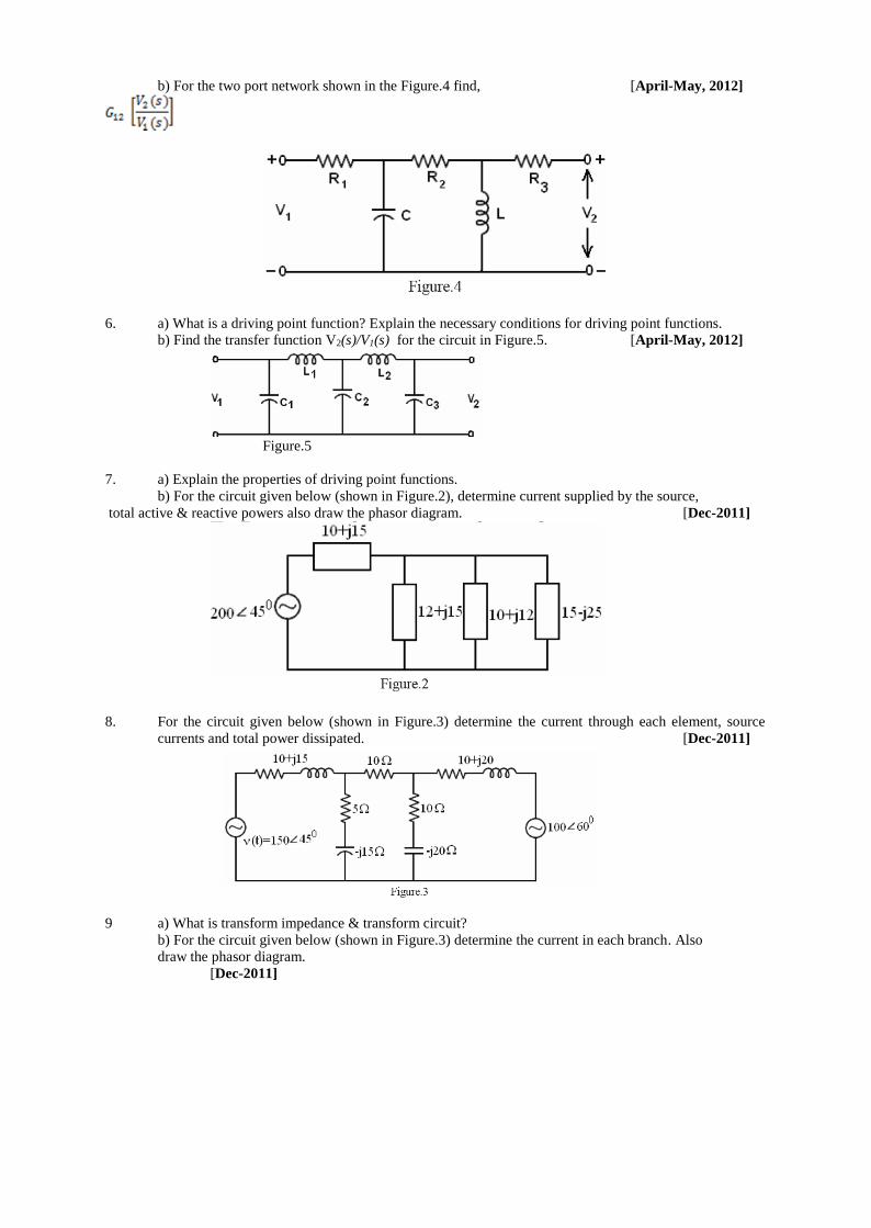
b) For the two port network shown in the Figure.4 find, [April-May, 2012]
6. a) What is a driving point function? Explain the necessary conditions for driving point functions.
b) Find the transfer function V2(s)/V1(s) for the circuit in Figure.5. [April-May, 2012]
Figure.5
7. a) Explain the properties of driving point functions.
b) For the circuit given below (shown in Figure.2), determine current supplied by the source,
total active & reactive powers also draw the phasor diagram. [Dec-2011]
8. For the circuit given below (shown in Figure.3) determine the current through each element, source
currents and total power dissipated. [Dec-2011]
9 a) What is transform impedance & transform circuit?
b) For the circuit given below (shown in Figure.3) determine the current in each branch. Also
draw the phasor diagram.
[Dec-2011]
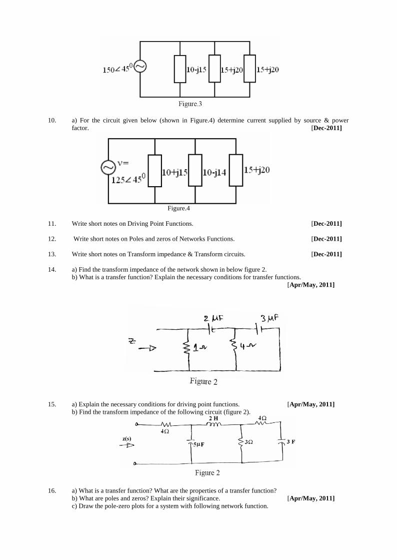
10. a) For the circuit given below (shown in Figure.4) determine current supplied by source & power
factor. [Dec-2011]
Figure.4
11. Write short notes on Driving Point Functions. [Dec-2011]
12. Write short notes on Poles and zeros of Networks Functions. [Dec-2011]
13. Write short notes on Transform impedance & Transform circuits. [Dec-2011]
14. a) Find the transform impedance of the network shown in below figure 2.
b) What is a transfer function? Explain the necessary conditions for transfer functions.
[Apr/May, 2011]
15. a) Explain the necessary conditions for driving point functions. [Apr/May, 2011]
b) Find the transform impedance of the following circuit (figure 2).
16. a) What is a transfer function? What are the properties of a transfer function?
b) What are poles and zeros? Explain their significance. [Apr/May, 2011]
c) Draw the pole-zero plots for a system with following network function.
)86(
)232()(
234
23
sss
ssSsZ
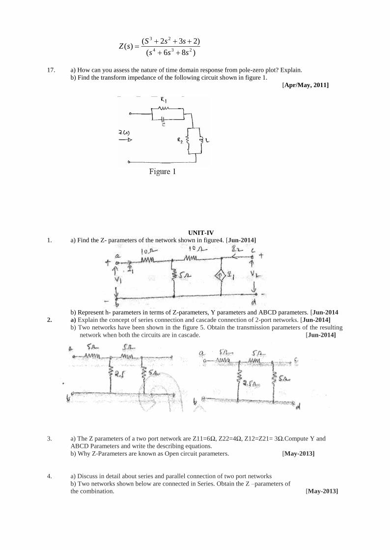
17. a) How can you assess the nature of time domain response from pole-zero plot? Explain.
b) Find the transform impedance of the following circuit shown in figure 1.
[Apr/May, 2011]
UNIT-IV
1. a) Find the Z- parameters of the network shown in figure4. [Jun-2014]
b) Represent h- parameters in terms of Z-parameters, Y parameters and ABCD parameters. [Jun-2014
2. a) Explain the concept of series connection and cascade connection of 2-port networks. [Jun-2014]
b) Two networks have been shown in the figure 5. Obtain the transmission parameters of the resulting
network when both the circuits are in cascade. [Jun-2014]
3. a) The Z parameters of a two port network are Z11=6Ω, Z22=4Ω, Z12=Z21= 3Ω.Compute Y and
ABCD Parameters and write the describing equations.
b) Why Z-Parameters are known as Open circuit parameters. [May-2013]
4. a) Discuss in detail about series and parallel connection of two port networks
b) Two networks shown below are connected in Series. Obtain the Z –parameters of
the combination. [May-2013]
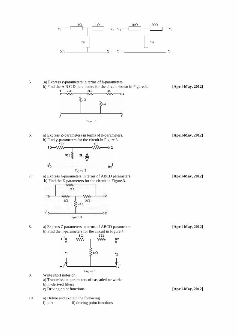
5 .a) Express y-parameters in terms of h-parameters.
b) Find the A B C D parameters for the circuit shown in Figure.3. [April-May, 2012]
6. a) Express Z-parameters in terms of h-parameters. [April-May, 2012]
b) Find y-parameters for the circuit in Figure.3.
7. a) Express h-parameters in terms of ABCD parameters. [April-May, 2012]
b) Find the Z-parameters for the circuit in Figure.3.
8. a) Express Z parameters in terms of ABCD parameters. [April-May, 2012]
b) Find the h-parameters for the circuit in Figure.4.
9. Write short notes on:
a) Transmission parameters of cascaded networks
b) m-derived filters
c) Driving point functions. [April-May, 2012]
10. a) Define and explain the following
i) port ii) driving point functions
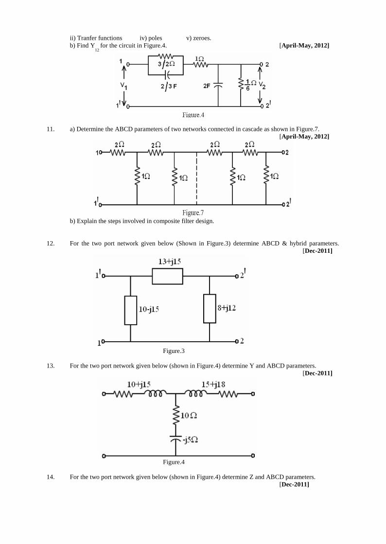
ii) Tranfer functions iv) poles v) zeroes.
b) Find Y12
for the circuit in Figure.4. [April-May, 2012]
11. a) Determine the ABCD parameters of two networks connected in cascade as shown in Figure.7.
[April-May, 2012]
b) Explain the steps involved in composite filter design.
12. For the two port network given below (Shown in Figure.3) determine ABCD & hybrid parameters.
[Dec-2011]
Figure.3
13. For the two port network given below (shown in Figure.4) determine Y and ABCD parameters.
[Dec-2011]
Figure.4
14. For the two port network given below (shown in Figure.4) determine Z and ABCD parameters.
[Dec-2011]
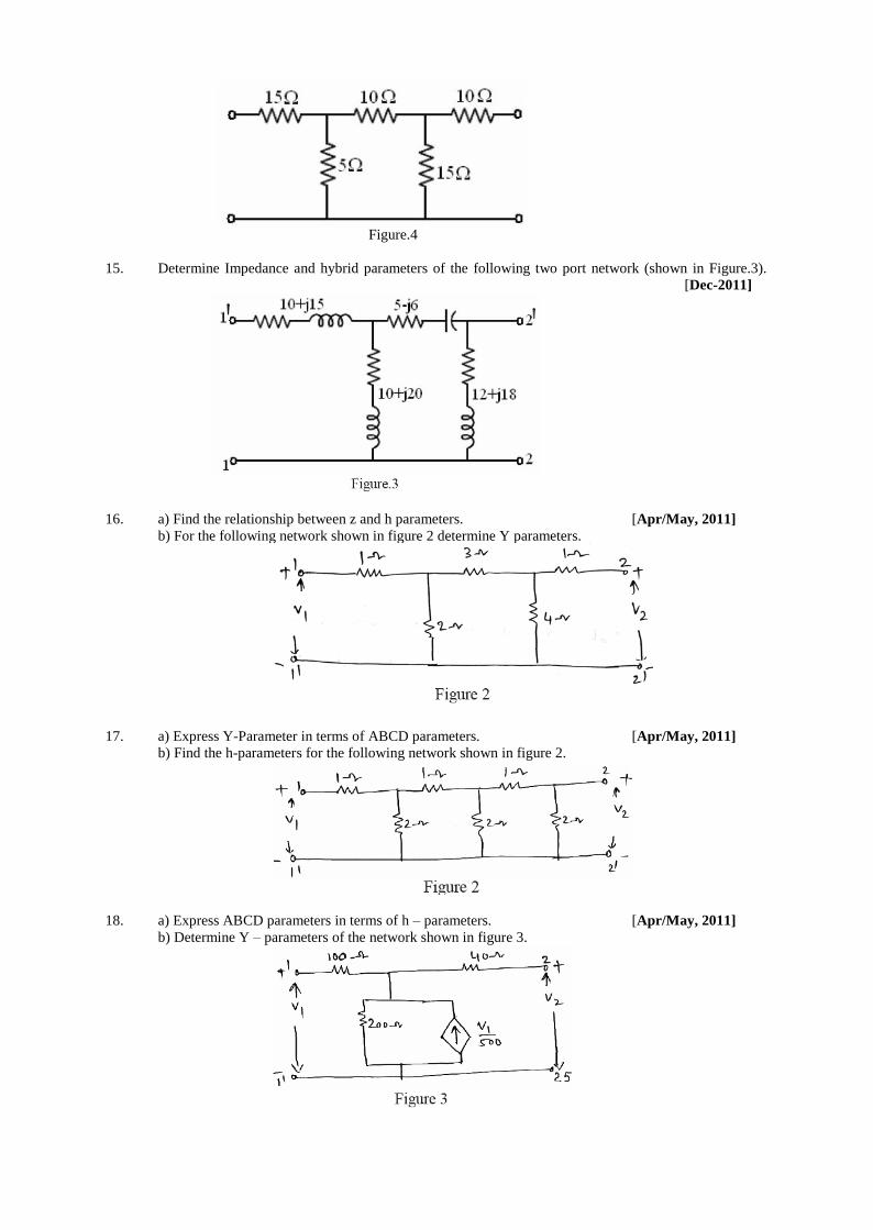
Figure.4
15. Determine Impedance and hybrid parameters of the following two port network (shown in Figure.3).
[Dec-2011]
16. a) Find the relationship between z and h parameters. [Apr/May, 2011]
b) For the following network shown in figure 2 determine Y parameters.
17. a) Express Y-Parameter in terms of ABCD parameters. [Apr/May, 2011]
b) Find the h-parameters for the following network shown in figure 2.
18. a) Express ABCD parameters in terms of h – parameters. [Apr/May, 2011]
b) Determine Y – parameters of the network shown in figure 3.
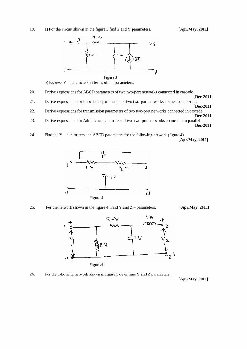
19. a) For the circuit shown in the figure 3 find Z and Y parameters. [Apr/May, 2011]
b) Express Y – parameters in terms of h – parameters.
20. Derive expressions for ABCD parameters of two two-port networks connected in cascade.
[Dec-2011]
21. Derive expressions for Impedance parameters of two two-port networks connected in series.
[Dec-2011]
22. Derive expressions for transmission parameters of two two-port networks connected in cascade.
[Dec-2011]
23. Derive expressions for Admittance parameters of two two-port networks connected in parallel.
[Dec-2011]
24. Find the Y – parameters and ABCD parameters for the following network (figure 4).
[Apr/May, 2011]
Figure.4
25. For the network shown in the figure 4. Find Y and Z – parameters. [Apr/May, 2011]
Figure.4
26. For the following network shown in figure 3 determine Y and Z parameters.
[Apr/May, 2011]
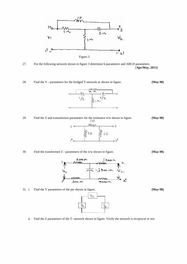
Figure.3
27. For the following network shown in figure 3 determine h-parameters and ABCD parameters.
[Apr/May, 2011]
28. Find the Y - parameters for the bridged T-network as shown in figure. (May 08)
29. Find the Z and transmission parameters for the resistance n/w shown in figure. (May 08)
30. Find the transformed Z - parameters of the n/w shown in figure. (May 08)
31. i. Find the Y parameters of the pie shown in figure. (May 08)
ii. Find the Z parameters of the T- network shown in figure. Verify the network is reciprocal or not.
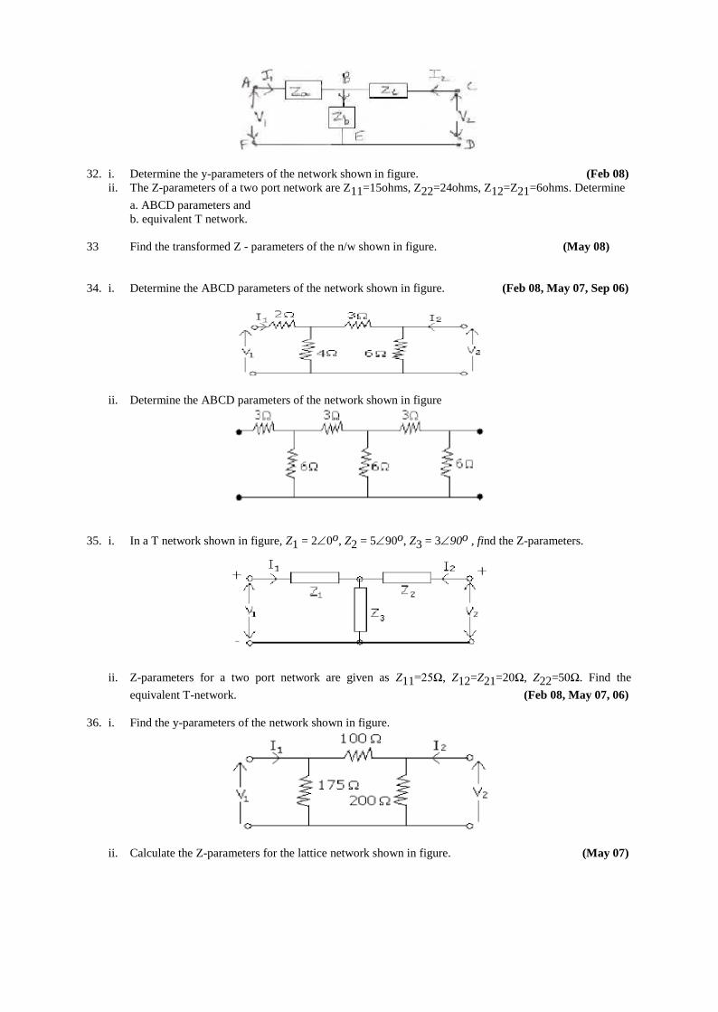
32. i. Determine the y-parameters of the network shown in figure. (Feb 08)
ii. The Z-parameters of a two port network are Z11=15ohms, Z22=24ohms, Z12=Z21=6ohms. Determine
a. ABCD parameters and
b. equivalent T network.
33 Find the transformed Z - parameters of the n/w shown in figure. (May 08)
34. i. Determine the ABCD parameters of the network shown in figure. (Feb 08, May 07, Sep 06)
ii. Determine the ABCD parameters of the network shown in figure
35. i. In a T network shown in figure, Z1 = 20o, Z2 = 590o, Z3 = 390o , find the Z-parameters.
ii. Z-parameters for a two port network are given as Z11=25Ω, Z12=Z21=20Ω, Z22=50Ω. Find the
equivalent T-network. (Feb 08, May 07, 06)
36. i. Find the y-parameters of the network shown in figure.
ii. Calculate the Z-parameters for the lattice network shown in figure. (May 07)
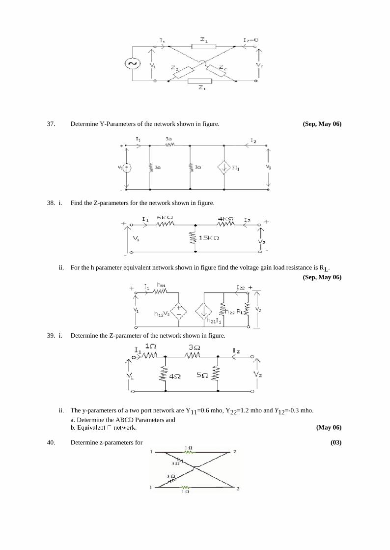
37. Determine Y-Parameters of the network shown in figure. (Sep, May 06)
38. i. Find the Z-parameters for the network shown in figure.
ii. For the h parameter equivalent network shown in figure find the voltage gain load resistance is RL.
(Sep, May 06)
39. i. Determine the Z-parameter of the network shown in figure.
ii. The y-parameters of a two port network are Y11=0.6 mho, Y22=1.2 mho and Y12=-0.3 mho.
a. Determine the ABCD Parameters and
(May 06)
40. Determine z-parameters for (03)
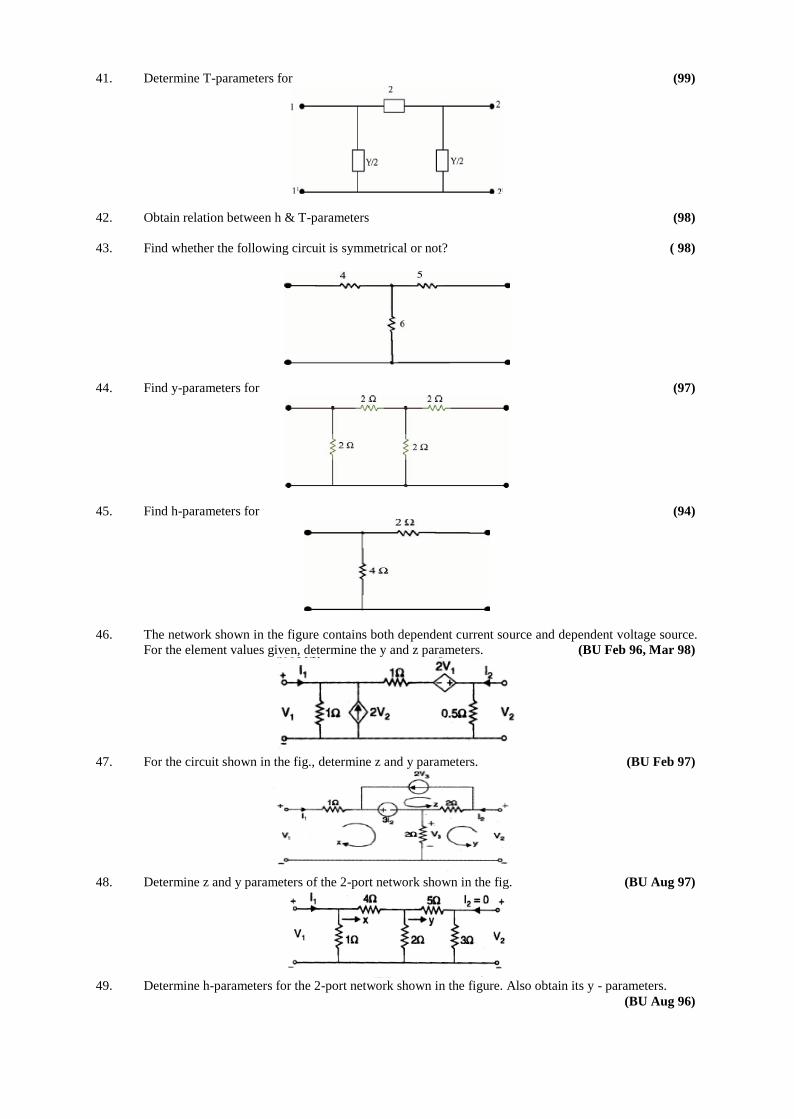
41. Determine T-parameters for (99)
42. Obtain relation between h & T-parameters (98)
43. Find whether the following circuit is symmetrical or not? ( 98)
44. Find y-parameters for (97)
45. Find h-parameters for (94)
46. The network shown in the figure contains both dependent current source and dependent voltage source.
For the element values given, determine the y and z parameters. (BU Feb 96, Mar 98)
47. For the circuit shown in the fig., determine z and y parameters. (BU Feb 97)
48. Determine z and y parameters of the 2-port network shown in the fig. (BU Aug 97)
49. Determine h-parameters for the 2-port network shown in the figure. Also obtain its y - parameters.
(BU Aug 96)
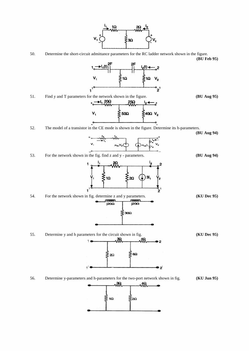
50. Determine the short-circuit admittance parameters for the RC ladder network shown in the figure.
(BU Feb 95)
51. Find y and T parameters for the network shown in the figure. (BU Aug 95)
52. The model of a transistor in the CE mode is shown in the figure. Determine its h-parameters.
(BU Aug 94)
53. For the network shown in the fig. find z and y - parameters. (BU Aug 94)
54. For the network shown in fig. determine z and y parameters. (KU Dec 95)
55. Determine y and h parameters for the circuit shown in fig. (KU Dec 95)
56. Determine y-parameters and h-parameters for the two-port network shown in fig. (KU Jun 95)
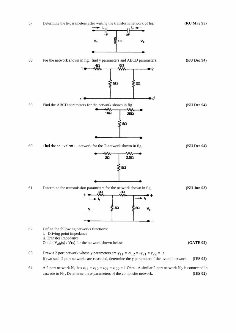
57. Determine the h-parameters after writing the transform network of fig. (KU May 95)
58. For the network shown in fig., find y parameters and ABCD parameters. (KU Dec 94)
59. Find the ABCD parameters for the network shown in fig. (KU Dec 94)
60. -network for the T-network shown in fig. (KU Dec 94)
61. Determine the transmission parameters for the network shown in fig. (KU Jun 93)
62. Define the following networks functions:
i. Driving point impedance
ii. Transfer Impedance
Obtain Vab(s) / V(s) for the network shown below: (GATE 02)
63. Draw a 2 port network whose y parameters are y11 = -y12 = -y21 = y22 = 1s.
If two such 2 port networks are cascaded, determine the y parameter of the overall network. (IES 02)
64. A 2 port network N1 has z11 = z12 = z21 = z 22 = 1 Ohm . A similar 2 port network N2 is connected in
cascade to N1, Determine the z-parameters of the composite network. (IES 02)
65. State the properties of driving point impedance of (i) LC Network (ii) RC network (IES 92)
66. A 2 port network made up of passive linear resistor is fed at port 1 by an ideal voltage source
of V volts.
It is loaded at port 2 by a resistance R:
i. With V = 10 volts and R = 6 Ohm currents of ports 1 and 2 were 1.44 and 0.2 A respectively.
ii. With V = 15 V and R = 8 Ohm the current at port 2 was 0.25 A
Determine the π equivalent circuit of the 2 port network. (IES 99)
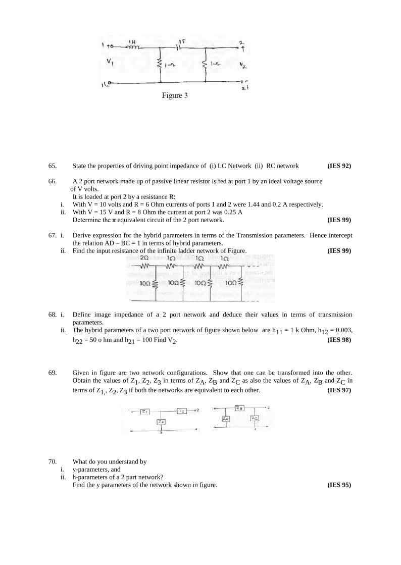
67. i. Derive expression for the hybrid parameters in terms of the Transmission parameters. Hence intercept
the relation AD – BC = 1 in terms of hybrid parameters.
ii. Find the input resistance of the infinite ladder network of Figure. (IES 99)
68. i. Define image impedance of a 2 port network and deduce their values in terms of transmission
parameters.
ii. The hybrid parameters of a two port network of figure shown below are h11 = 1 k Ohm, h12 = 0.003,
h22 = 50 o hm and h21 = 100 Find V2. (IES 98)
69. Given in figure are two network configurations. Show that one can be transformed into the other.
Obtain the values of Z1, Z2, Z3 in terms of ZA, ZB and ZC as also the values of ZA, ZB and ZC in
terms of Z1,, Z2, Z3 if both the networks are equivalent to each other. (IES 97)
70. What do you understand by
i. y-parameters, and
ii. h-parameters of a 2 part network?
Find the y parameters of the network shown in figure. (IES 95)
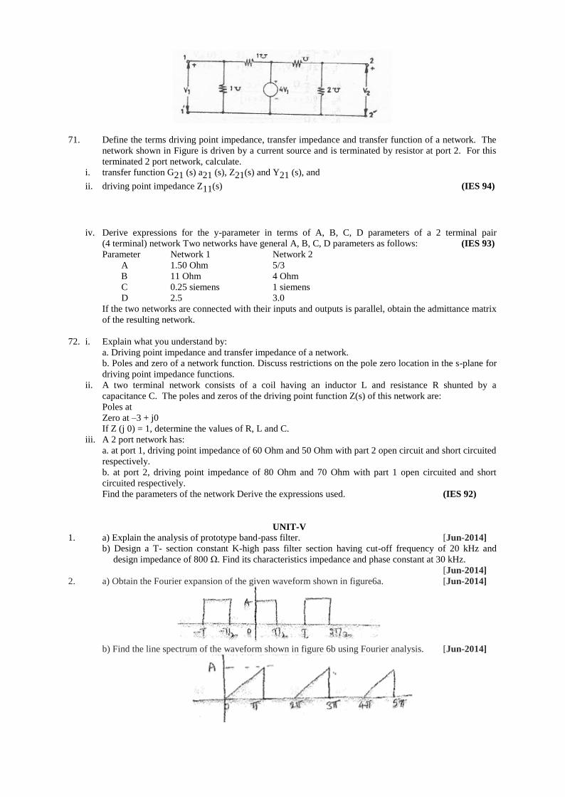
71. Define the terms driving point impedance, transfer impedance and transfer function of a network. The
network shown in Figure is driven by a current source and is terminated by resistor at port 2. For this
terminated 2 port network, calculate.
i. transfer function G21 (s) a21 (s), Z21(s) and Y21 (s), and
ii. driving point impedance Z11(s) (IES 94)
iv. Derive expressions for the y-parameter in terms of A, B, C, D parameters of a 2 terminal pair
(4 terminal) network Two networks have general A, B, C, D parameters as follows: (IES 93)
Parameter Network 1 Network 2
A 1.50 Ohm 5/3
B 11 Ohm 4 Ohm
C 0.25 siemens 1 siemens
D 2.5 3.0
If the two networks are connected with their inputs and outputs is parallel, obtain the admittance matrix
of the resulting network.
72. i. Explain what you understand by:
a. Driving point impedance and transfer impedance of a network.
b. Poles and zero of a network function. Discuss restrictions on the pole zero location in the s-plane for
driving point impedance functions.
ii. A two terminal network consists of a coil having an inductor L and resistance R shunted by a
capacitance C. The poles and zeros of the driving point function Z(s) of this network are:
Poles at
Zero at –3 + j0
If Z (j 0) = 1, determine the values of R, L and C.
iii. A 2 port network has:
a. at port 1, driving point impedance of 60 Ohm and 50 Ohm with part 2 open circuit and short circuited
respectively.
b. at port 2, driving point impedance of 80 Ohm and 70 Ohm with part 1 open circuited and short
circuited respectively.
Find the parameters of the network Derive the expressions used. (IES 92)
UNIT-V
1. a) Explain the analysis of prototype band-pass filter. [Jun-2014]
b) Design a T- section constant K-high pass filter section having cut-off frequency of 20 kHz and
design impedance of 800 Ω. Find its characteristics impedance and phase constant at 30 kHz.
[Jun-2014]
2. a) Obtain the Fourier expansion of the given waveform shown in figure6a. [Jun-2014]
b) Find the line spectrum of the waveform shown in figure 6b using Fourier analysis. [Jun-2014]
3 a) Derive the expression for cutoff frequency in case of Constant K Low pass filter.
b)Design a low pass filter (both T and π sections) having a cutoff frequency of 2 KHz to operate with
a terminated load resistance of 500 Ω. [May-2013]
4. a) Explain the design procedure for a constant K low pass filter and its characteristics.
b) Find the component values of a constant K LPF having characteristic impedance
Z0
= 500Ω and cut off frequency of fc
= 500 Hz. Find the frequency at which this filter produces an
alternation constant of 38.2 dB. [April-May, 2012]
5. a) Give the analysis for the design of constant K band elimination filter and explain its characteristics.
b) Design a constant K band elimination filter with cut off frequency 1750 Hz to 4250 Hz and a
characteristic impedance of 250Ω. [April-May, 2012]
6. Write short notes on [April-May, 2012]
a)Composite filters
b)m-derived low pass filter
7. a) Give the analysis for the design of constant-K band pass filter. [April-May, 2012]
b) Design a prototype band pass filter section having cut off frequencies of 2000 Hz and 5000 Hz and
nominal characteristic impedance of 600Ω.
8. a) Explain the design procedure for constant K high pass filter for symmetrical T and П sections and
discuss its characteristics. [April-May, 2012]
b) Find the component values of П-section & T-section constant-K high pass filter having a cut off
frequency of 8 kHz and nominal characteristic impedance of 500Ω. Find its characteristic impedance
and phase constant at f = 12 kHz and attenuation at f = 1 kHz.
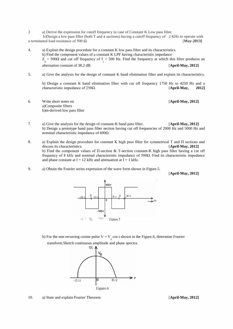
9. a) Obtain the Fourier series expression of the wave form shown in Figure.5.
[April-May, 2012]
b) For the non recurring cosine pulse V = V0 cos t shown in the Figure.6, determine Fourier
transform.Sketch continuous amplitude and phase spectra.
10. a) State and explain Fourier Theorem. [April-May, 2012]
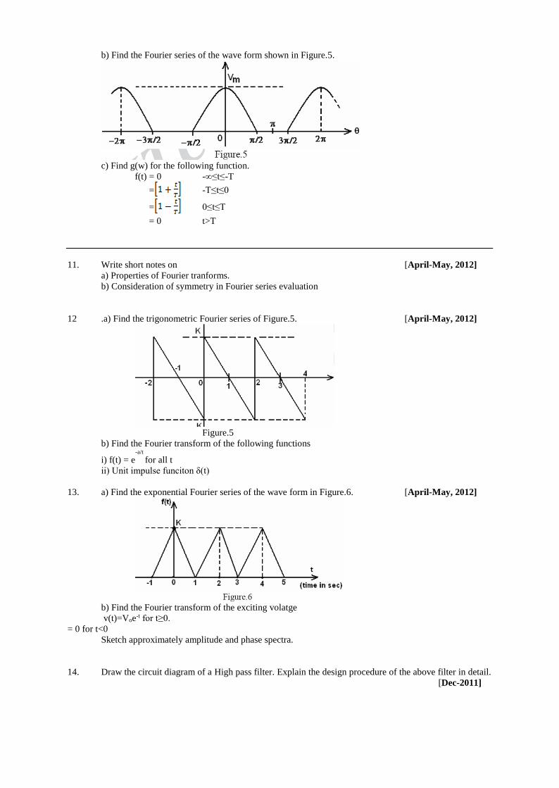
b) Find the Fourier series of the wave form shown in Figure.5.
c) Find g(w) for the following function.
f(t) = 0 -∞≤t≤-T
= -T≤t≤0
= 0≤t≤T
= 0 t>T
11. Write short notes on [April-May, 2012]
a) Properties of Fourier tranforms.
b) Consideration of symmetry in Fourier series evaluation
12 .a) Find the trigonometric Fourier series of Figure.5. [April-May, 2012]
Figure.5
b) Find the Fourier transform of the following functions
i) f(t) = e-a/t
for all t
ii) Unit impulse funciton δ(t)
13. a) Find the exponential Fourier series of the wave form in Figure.6. [April-May, 2012]
b) Find the Fourier transform of the exciting volatge
v(t)=Voe-t for t≥0.
= 0 for t<0
Sketch approximately amplitude and phase spectra.
14. Draw the circuit diagram of a High pass filter. Explain the design procedure of the above filter in detail.
[Dec-2011]

15. Draw the circuit diagram of a Band pass filter. Explain the design procedure of the above filter in detail.
[Dec-2011]
16. Design a symmetrical T attenuator to give 2 dB attenuation to have a characteristic impedance of 150Ω.
[Dec-2011]
17. Design a symmetrical T-attenuation to give 20 dB attenuation and to have characteristic impedance of
300Ω. [Dec-2011]
18. Write short notes on Low pass filter. [Dec-2011]
19. Write short notes on properties of Fourier transform. [Dec-2011]
20. Write short notes on
a) Phase angle spectra.
b) Fourier transform properties. [Dec-2011]
21. Write short notes on
a) Line and phase angle spectra
b) Fourier integrals [Dec-2011]
22. Write short notes on
a) Fourier transform theorems.
b) Exponential form of Fourier series [Dec-2011]
23. a) What is a band pass filter? Explain the general configuration and various parameters of
constant-k band pass filters for T and Π-Sections.
b) What are the steps involved in design of composite filter? [Apr/May, 2011]
24. a) What is an m-derived filter? Explain the general configuration and parameters of m- derived
low pass filter for T and Π-Sections.
b) Design an m derived high pass Π-Section filter having a cut off frequency 3250 Hz. The
frequency of infinite attenuation may be taken at 2750 Hz. The characteristic impedance is 450Ω.
[Apr/May, 2011]
25. a) What is high pass filter? Explain the general configuration and parameters of a constant –
K high pass filter.
b) Design a constant - K T – section and π- section high pass filter having cut off frequency fc = 10
KHz and characteristic impedance Z0= 600Ω. Also find the characteristic impedance at 25 KHz.
[Apr/May, 2011]
26. a) Explain the general configuration and parameters of a constant - K low pass filter T and π - Sections.
b) Design a constant–K T-Section and π - section low pass filter having cut off frequency fc = 2kHz
and normal impedance Z0 = 600 Ω. [Apr/May, 2011]
27. Design a band stop, constant – K filter with cut off frequencies of 4 KHz and 10 KHz and nominal
characteristic impedance of 500 Ω. [Apr/May, 2011]
28. Design a band pass, constant – K filter with cut – off frequency of 4 KHz and nominal characteristic
impedance of 500 Ω. [Apr/May, 2011]
29. Design a low pass constant – K (i) T – Section and (ii) π – section filter with cut – off frequency (fc
) 6
kHz and nominal characteristic impedance of 500 Ω. [Apr/May, 2011]

30. A high pass constant – K filter with cut – off frequency 40 kHz is required to procedure a maximum
attenuation at 36 kHz when used with terminated resistance of 500 Ω. Design a suitable m – derived T –
section. [Apr/May, 2011]
31. Design a band elimination filter having a design impedance of 600Ω and cut – off frequencies
f1 = 2 KHz and f
2 = 6 KHZ. Design a m – derived high pass filter with a cut – off frequency of 10KHz;
design impedance of 5Ω and m = 0.4. [Apr/May, 2011]
32. a) Determine the function f(t) if the Fourier Transform of the function is
F(jw) = A ejπ/2
-w0 < w < 0
A e-jπ/2
0 < w < w0
b) Determine the Fourier series of the wave form shown in figure.5using Trigonometric series.
[Apr/May, 2011]
33. a) State and explain Fourier Theorem. [Apr/May, 2011]
b) The sweep voltage wave form is shown in the figure 4 given below. Find the exponential form of the
Fourier series. Draw the frequency and phase spectrums.
Figure.4
34. a) Find the exponential form of the Fourier Series expansion for the periodic rectangular pulse train
shown in figure 4. Also draw frequency spectrum taking
T
Tp=
6
1 [Apr/May, 2011]
Figure.4
b) What are the properties of Fourier Transform?
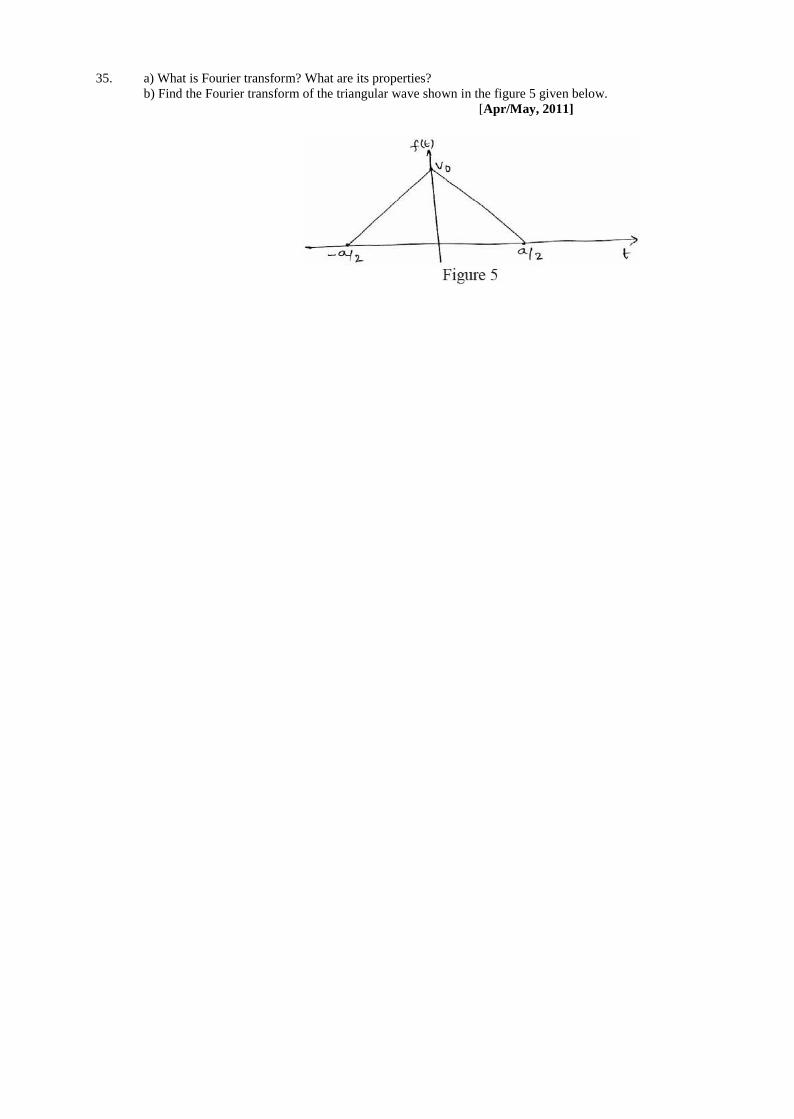
35. a) What is Fourier transform? What are its properties?
b) Find the Fourier transform of the triangular wave shown in the figure 5 given below.
[Apr/May, 2011]

Assignment Questions
UNIT-I
1. The phase voltage of a star-connected three- phase ac generator is 230V.Calculate the (i) Line voltage
(ii) active power output if the line current of the system is 15 A at a power factor of 0.7 and (iii) active
and reactive components of the phase currents.
2. A three-phase delta- connected RYB system with an effective voltage of 400V has a balanced with
impedances 3+j4 calculate the (i) phase current (ii) line currents and (iii) power in each phase.
3. The power consumed in a three phase balanced star-connected load is 2 kW at a power factor of 0.8
lagging. The supply voltage is 400V, 50Hz.Calculate the resistance and reactance of each phase.
4. Calculate the total power input and reading of the two wattmeters connected to measure power in a
three-phase balanced load if the reactive power input is 15 KVAR, and the load pf is 0.8
5. Two wattmeter’s are connected to measure power in a three-phase circuit. The reading of the one of the
Meter is 5kW when the load power factor is unity if the power factor of the load is changed to 0.707
lagging, without changing the total input power, calculate the readings of the two wattmeter’s.
6. Find the line currents & the total power consumed by the unbalanced delta-connected load shown Fig.
7. Explain the relationship between line and phase quantities in star and delta connected systems with
phasor diagrams.
8. Explain the different methods to determine active and reactive power in a 3-Ø circuit.
UNIT-II
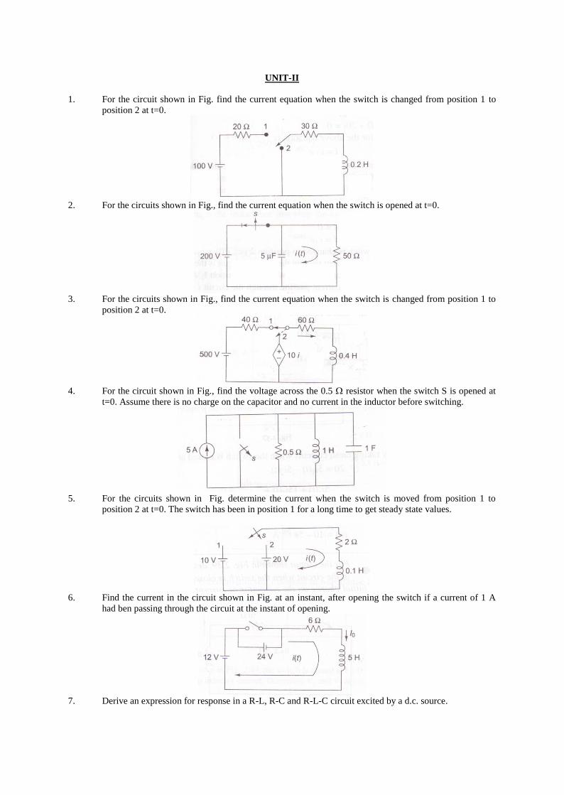
1. For the circuit shown in Fig. find the current equation when the switch is changed from position 1 to
position 2 at t=0.
2. For the circuits shown in Fig., find the current equation when the switch is opened at t=0.
3. For the circuits shown in Fig., find the current equation when the switch is changed from position 1 to
position 2 at t=0.
4. For the circuit shown in Fig., find the voltage across the 0.5 resistor when the switch S is opened at
t=0. Assume there is no charge on the capacitor and no current in the inductor before switching.
5. For the circuits shown in Fig. determine the current when the switch is moved from position 1 to
position 2 at t=0. The switch has been in position 1 for a long time to get steady state values.
6. Find the current in the circuit shown in Fig. at an instant, after opening the switch if a current of 1 A
had ben passing through the circuit at the instant of opening.
7. Derive an expression for response in a R-L, R-C and R-L-C circuit excited by a d.c. source.
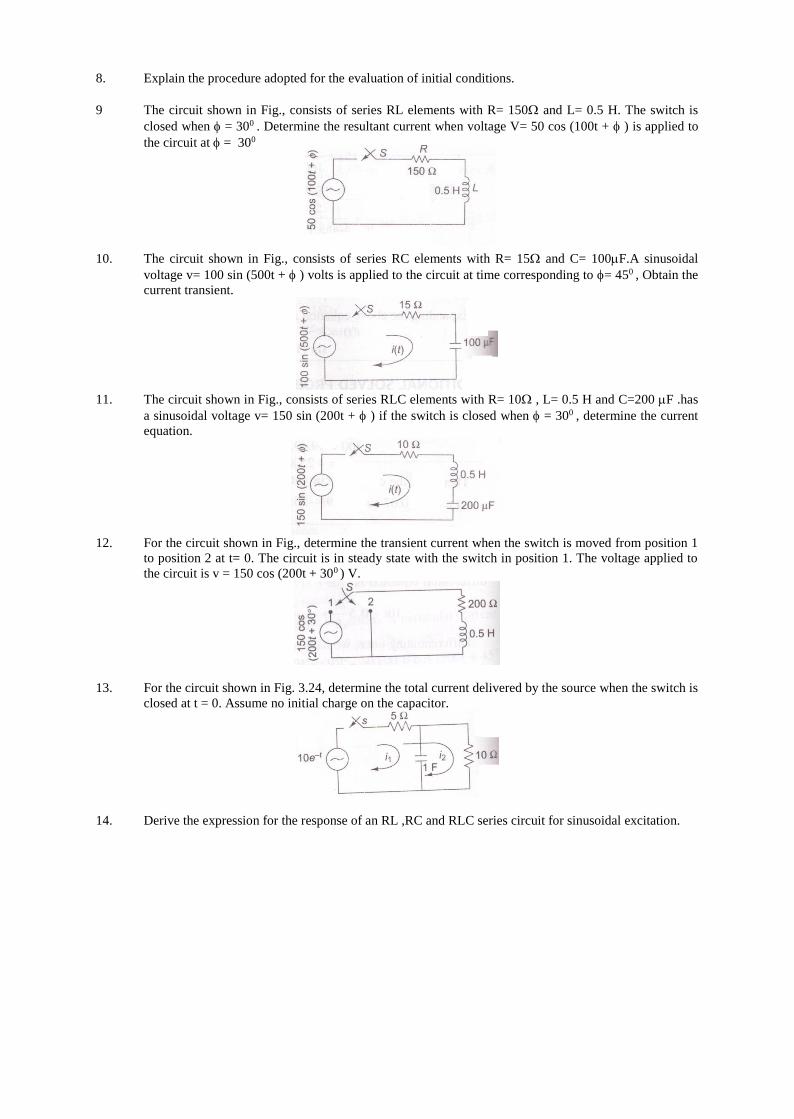
8. Explain the procedure adopted for the evaluation of initial conditions.
9 The circuit shown in Fig., consists of series RL elements with R= 150 and L= 0.5 H. The switch is
closed when = 300 . Determine the resultant current when voltage V= 50 cos (100t + ) is applied to
the circuit at = 300
10. The circuit shown in Fig., consists of series RC elements with R= 15 and C= 100F.A sinusoidal
voltage v= 100 sin (500t + ) volts is applied to the circuit at time corresponding to = 450 , Obtain the
current transient.
11. The circuit shown in Fig., consists of series RLC elements with R= 10 , L= 0.5 H and C=200 F .has
a sinusoidal voltage v= 150 sin (200t + ) if the switch is closed when = 300 , determine the current
equation.
12. For the circuit shown in Fig., determine the transient current when the switch is moved from position 1
to position 2 at t= 0. The circuit is in steady state with the switch in position 1. The voltage applied to
the circuit is v = 150 cos (200t + 300 ) V.
13. For the circuit shown in Fig. 3.24, determine the total current delivered by the source when the switch is
closed at t = 0. Assume no initial charge on the capacitor.
14. Derive the expression for the response of an RL ,RC and RLC series circuit for sinusoidal excitation.
UNIT- III
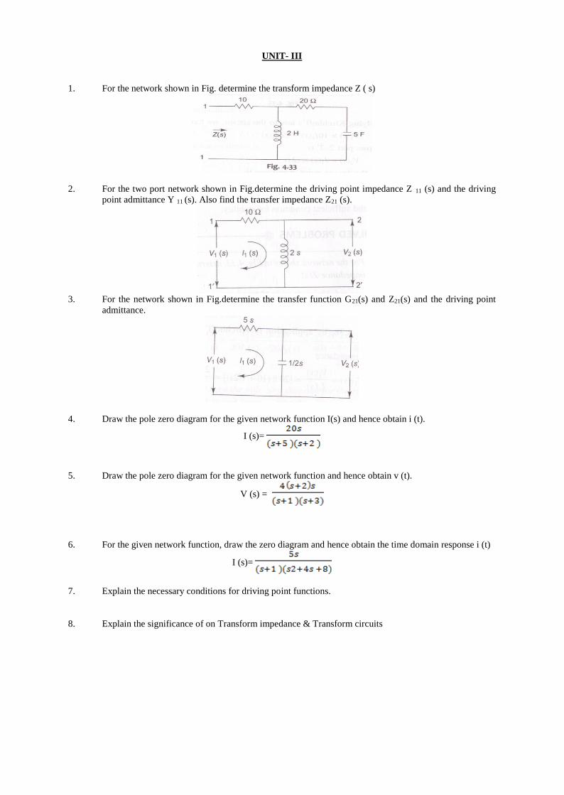
1. For the network shown in Fig. determine the transform impedance Z ( s)
2. For the two port network shown in Fig.determine the driving point impedance Z 11 (s) and the driving
point admittance Y 11 (s). Also find the transfer impedance Z21 (s).
3. For the network shown in Fig.determine the transfer function G21(s) and Z21(s) and the driving point
admittance.
4. Draw the pole zero diagram for the given network function I(s) and hence obtain i (t).
I (s)=
5. Draw the pole zero diagram for the given network function and hence obtain v (t).
V (s) =
6. For the given network function, draw the zero diagram and hence obtain the time domain response i (t)
I (s)=
7. Explain the necessary conditions for driving point functions.
8. Explain the significance of on Transform impedance & Transform circuits
UNIT- IV
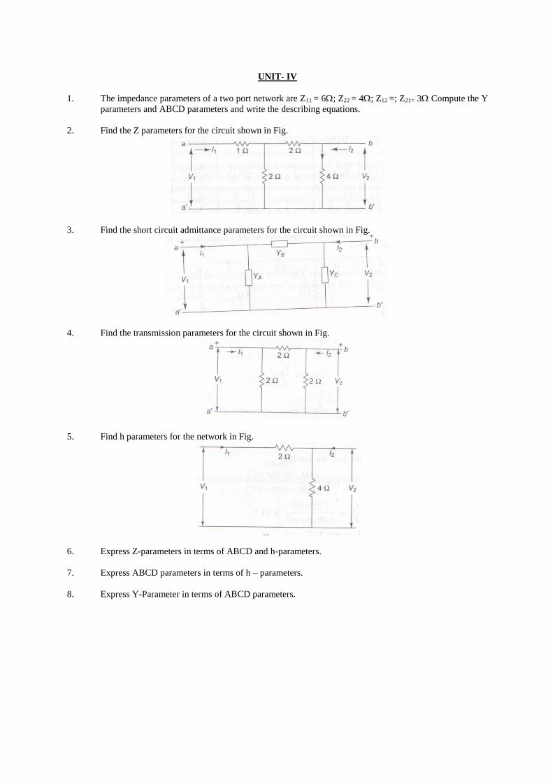
1. The impedance parameters of a two port network are Z11 = 6; Z22 = 4; Z12 =; Z21= 3 Compute the Y
parameters and ABCD parameters and write the describing equations.
2. Find the Z parameters for the circuit shown in Fig.
3. Find the short circuit admittance parameters for the circuit shown in Fig.
4. Find the transmission parameters for the circuit shown in Fig.
5. Find h parameters for the network in Fig.
6. Express Z-parameters in terms of ABCD and h-parameters.
7. Express ABCD parameters in terms of h – parameters.
8. Express Y-Parameter in terms of ABCD parameters.
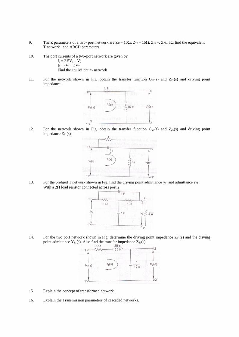
9. The Z parameters of a two- port network are Z11= 10; Z22 = 15; Z12 =; Z21= 5 find the equivalent
T network and ABCD parameters.
10. The port currents of a two-port network are given by
I1 = 2.5V1 – V2
I1 = -V1 – 5V2
Find the equivalent π- network.
11. For the network shown in Fig. obtain the transfer function G21(s) and Z21(s) and driving point
impedance.
12. For the network shown in Fig. obtain the transfer function G21(s) and Z21(s) and driving point
impedance Z11(s)
13. For the bridged T network shown in Fig. find the driving point admittance y11 and admittance y21
With a 2 load resistor connected across port 2.
14. For the two port network shown in Fig. determine the driving point impedance Z11(s) and the driving
point admittance Y11(s). Also find the transfer impedance Z21(s)
15. Explain the concept of transformed network.
16. Explain the Transmission parameters of cascaded networks.
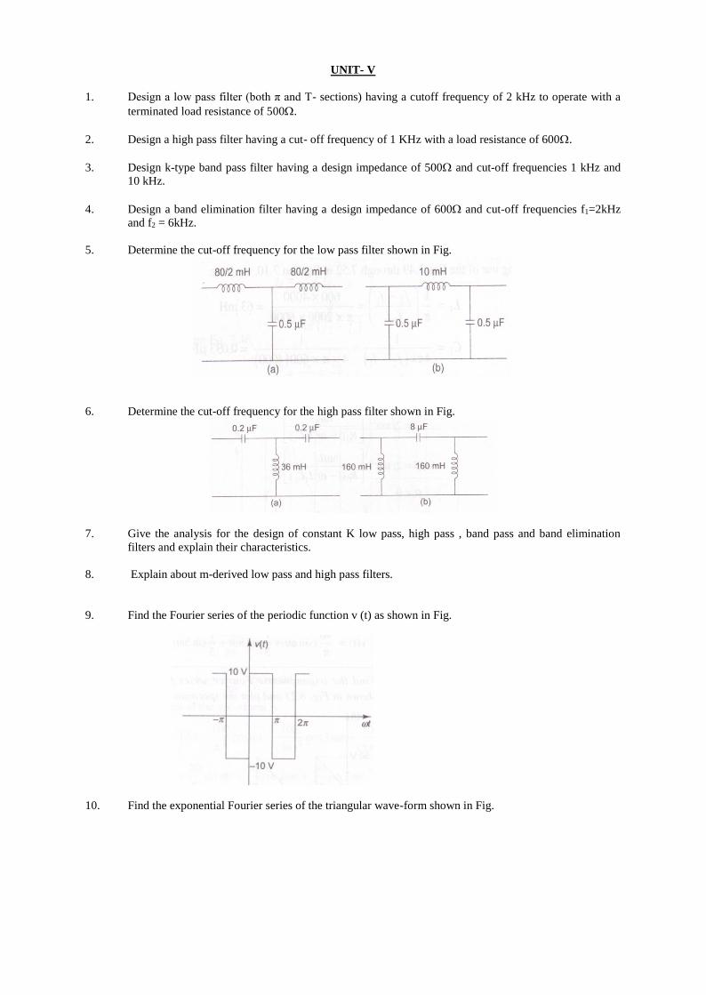
UNIT- V
1. Design a low pass filter (both π and T- sections) having a cutoff frequency of 2 kHz to operate with a
terminated load resistance of 500.
2. Design a high pass filter having a cut- off frequency of 1 KHz with a load resistance of 600.
3. Design k-type band pass filter having a design impedance of 500 and cut-off frequencies 1 kHz and
10 kHz.
4. Design a band elimination filter having a design impedance of 600 and cut-off frequencies f1=2kHz
and f2 = 6kHz.
5. Determine the cut-off frequency for the low pass filter shown in Fig.
6. Determine the cut-off frequency for the high pass filter shown in Fig.
7. Give the analysis for the design of constant K low pass, high pass , band pass and band elimination
filters and explain their characteristics.
8. Explain about m-derived low pass and high pass filters.
9. Find the Fourier series of the periodic function v (t) as shown in Fig.
10. Find the exponential Fourier series of the triangular wave-form shown in Fig.
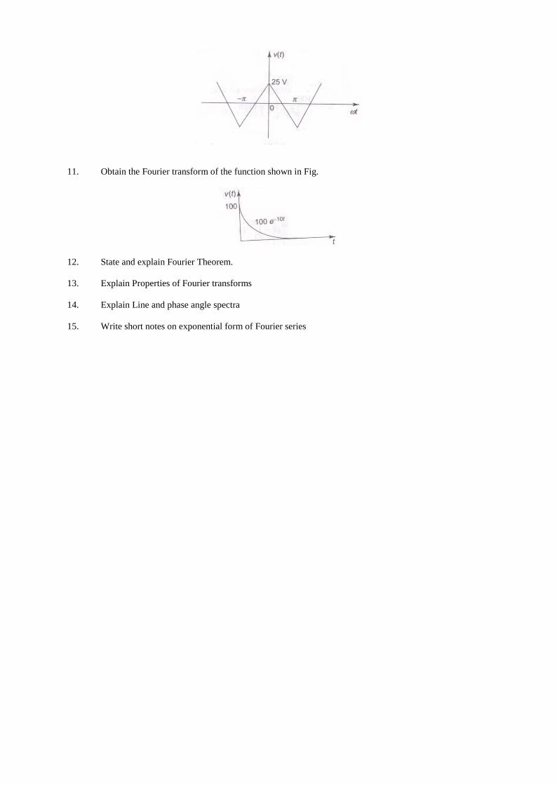
11. Obtain the Fourier transform of the function shown in Fig.
12. State and explain Fourier Theorem.
13. Explain Properties of Fourier transforms
14. Explain Line and phase angle spectra
15. Write short notes on exponential form of Fourier series