Embed Size (px)
Citation preview

OL-25801-01
C H A P T E R 4
Network WizardIntroductionThis chapter describes how a user can configure the network topology on the application.
This chapter contains the following sections:
• Defining a Network, page 4-2
• Managing Network Devices, page 4-3
• Setting Master Device, page 4-3
• Defining Device Topology, page 4-6
• Defining Service Hierarchy (for SCE networks), page 4-13
• Managing Report Filters, page 4-16
• Assigning Custom Colors, page 4-17
The Network wizard allows creating a network, managing network devices, and defining device topology by driving you across all mandatory settings.
After the configuration of external databases is complete and all devices (SCEs and ASR1Ks) are provisioned, the administrator can create a list of networks. Networks are used to group devices sharing the same configuration in order to produce reports for aggregated traffic
Administrators can add networks and group devices for reporting. Each device to be used in reporting must be associated to at least one network. The network definition includes the device topology and service or application hierarchy. A service or application hierarchy of a network is the service or application definition of its master device on the Traffic Database.
Note The Cisco Insight Reporter currently works with Networks containing either SCE or ASR1K devices (no mixed -device networks).
Data can only be aggregated for devices belonging to same network.
Network cannot be made of devices whose information is stored on different traffic (remote) DBs. Thus traffic can be aggregated only for devices whose data is stored on a specific DB and belonging to the same Network.
Since Cisco Insight Reporter references the configurations of all devices in a network through the Master, they should share the same configuration (services/application tree, packages and zones) as of the Master Device.
4-1Cisco Insight Reporter User Guide, v3.1.0

Chapter 4 Network Wizard Defining a Network
Defining a NetworkNetworks are the source of the data traffic information required for reporting. You must define a network connection before you run a report.
To access and display the Network tab, click the Network Wizard icon on the module launcher.
In this tab, you can:
• Configure a New Network, page 4-2
• Delete an Existing Network, page 4-3
Configure a New NetworkTo configure a new network, perform the following steps:
Step 1 Choose the New option.
After you select the New option in the Network tab, you see:
Figure 4-1 Defining a Network
Enter the Name and Description of the network to be configured.
Step 2 Click the Cancel button to return to the previous page, or click the Save button to confirm.
4-2Cisco Insight Reporter User Guide, v3.1.0
OL-25801-01

Chapter 4 Network Wizard Delete an Existing Network
The network list gets updated on the screen.
Delete an Existing NetworkTo delete a network, perform the following steps:
Step 1 Select the network from the list of networks.
Step 2 Choose Delete option. A dialog box appears asking you to confirm the deletion.
Step 3 Click the Cancel button to return to the previous page, or click the Save button to confirm.
The network list gets updated on the screen.
Note Network deletion can lead to the following consequences
• It deletes scheduled reports on the same network.
• It vanishes all reports related to that network and configured on the Dashboard
• It deletes all entries of My Favorites reports of the specific network.
Managing Network DevicesThe Devices tab displays all configured databases (both SCE and ASR1K) and devices, enabling you to report on data traffic information of the selected devices.
To access and display the Devices tab, click the Network Wizard icon on the module launcher.
Setting Master DeviceAfter you select the device, you should select a master SCE/ASR1K, to be used as reference for the service configuration. All devices of a particular network should share same configuration i.e. services or applications, out of which, user can select one of the device as a master device. Network uses this device as a reference device and creates service tree, packages and zones in case of SCE networks and application tree for ASR1K based networks.
To set a master device, perform the following steps:
Step 1 Select the device to be set as master.
Step 2 Click Set as Master.
4-3Cisco Insight Reporter User Guide, v3.1.0
OL-25801-01

Chapter 4 Network Wizard Setting Master Device
When you set a master device, you see:
Figure 4-2 Setting Master Device (SCE)
4-4Cisco Insight Reporter User Guide, v3.1.0
OL-25801-01

Chapter 4 Network Wizard Enabling device views for ASR Networks
Figure 4-3 Setting Master Device (ASR)
Note You cannot delete the master device, unless a new master is defined.
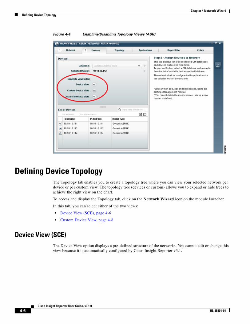
Enabling device views for ASR NetworksOn the Device tab of the network for ASR devices, the user can choose to activate or deactivate the topology view for that network. User can choose to deactivate Device View and Custom Interface View, so that these are not available for other to select. If any view is deactivated, it is disabled in the Network Topology and Report Wizard and cannot be selected while generating reports.
4-5Cisco Insight Reporter User Guide, v3.1.0
OL-25801-01
Chapter 4 Network Wizard Defining Device Topology
Figure 4-4 Enabling/Disabling Topology Views (ASR)
Defining Device TopologyThe Topology tab enables you to create a topology tree where you can view your selected network per device or per custom view. The topology tree (devices or custom) allows you to expand or hide trees to achieve the right view on the chart.
To access and display the Topology tab, click on the Network Wizard icon on the module launcher.
In this tab, you can select either of the two views:
• Device View (SCE), page 4-6
• Custom Device View, page 4-8
Device View (SCE)The Device View option displays a pre-defined structure of the networks. You cannot edit or change this view because it is automatically configured by Cisco Insight Reporter v3.1.
4-6Cisco Insight Reporter User Guide, v3.1.0
OL-25801-01

Chapter 4 Network Wizard Device View (SCE)
When you select Device Type View, you see:
Figure 4-5 Device View
4-7Cisco Insight Reporter User Guide, v3.1.0
OL-25801-01

Chapter 4 Network Wizard Custom Device View
Custom Device ViewThe Custom Device View is used to group network devices according to the customer needs. This view is represented by a hierarchical tree structure. You can define new levels of aggregations and arrange devices (SCEs or ASR1Ks) in logical groups (that is, POPs, cities, regions, etc.). In such tree structures, the root element is the network name, the SCEs or ASR1Ks are the leaves of the hierarchical tree, and intermediate nodes may represent the geographical aggregations. All nodes can be collapsed or expanded down to the device level.
As soon as a network is defined, the custom view of the topology is just a flat tree containing all the devices as children elements of a unique node (the network name).
When you select the Custom Device View, you see:
Figure 4-6 Custom Device View
To define a Custom Device, perform the following steps:
Step 1 Select the Network (for example, Mobile) to create the groups by region,
Step 2 Select Create Group. A new window appears.
4-8Cisco Insight Reporter User Guide, v3.1.0
OL-25801-01

Chapter 4 Network Wizard Custom Device View
Figure 4-7 Create Group
Step 3 Enter the Name of the group (for example, East Coast, West Coast, etc.).
Step 4 Click the Cancel button to return to previous page, or click the Save button to confirm.
Note Follow the same procedure, if you want to add more groups at the same level.
Step 5 Select the region (for example, East Coast) to create a subgroups by cities.
Step 6 Select Create Group. A new window appears.
Step 7 Enter the Name of the group (for example, New York, Boston, etc.).
Step 8 Click the Cancel button to return to previous page, or click the Save button to confirm.
Note Follow the same procedure, if you want to add more subgroups at the same level.
Step 9 Check the check boxes for the SCEs that you want to move under the subgroups.
Step 10 Select Move Items. A new window appears.
Step 11 Select the subgroup New York.
Step 12 Click the Cancel button to discard changes, or click the Move button to confirm. All the SCEs get listed under the subgroup New York.
Note Follow the same procedure, if you want to add the devices under the groups as well.
4-9Cisco Insight Reporter User Guide, v3.1.0
OL-25801-01

Chapter 4 Network Wizard Defining Interface Preferences (ASR1K)
Step 13 Select the group that you want to dissolve.
Step 14 Select Dissolve Group. The group will appear as a flat tree.
Note There is no limit to the number of elements contained within a specific level, because there is no limit to the number of intermediate levels.
Defining Interface Preferences (ASR1K)When working with the ASR device based networks, user can choose to set preferences for the interfaces of the selected ASR devices. To set the interface preferences,
Step 1 Open the network wizard, select the network and go to the Topology tab.
Step 2 Select Custom Device View and click on Interface Preferences.
Step 3 Make choices in the Interface Preference Overlay.
Note The interfaces for the devices are fetched from the traffic database (NF_INI_VALUES) table on the device discovery process. If an interface for a device has associated traffic data in the RPT_USAGE_NF, it is shown in GREEN color otherwise in RED color on the Interface Preference overlay window.
Application allows user to set preferences for:
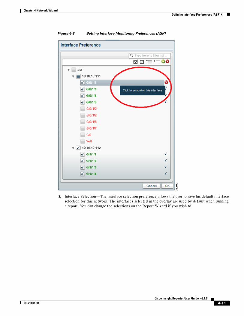
1. Interface Monitoring—Only a monitored interface will be visible in the Report Wizard for the user to select and generate report on. If an interface has associated traffic (is Green), it is marked as monitored by default, but the user can choose to un-monitor them if he doesn't want to see them on the report wizard. Similarly even if some interfaces may not have associated traffic (in Red), user can still choose to keep them monitored and view them in report wizard assuming that the traffic may be generated for such interfaces before selecting and running report for them.
4-10Cisco Insight Reporter User Guide, v3.1.0
OL-25801-01
Chapter 4 Network Wizard Defining Interface Preferences (ASR1K)
Figure 4-8 Setting Interface Monitoring Preferences (ASR)
2. Interface Selection—The interface selection preference allows the user to save his default interface selection for this network. The interfaces selected in the overlay are used by default when running a report. You can change the selections on the Report Wizard if you wish to.
4-11Cisco Insight Reporter User Guide, v3.1.0
OL-25801-01

Chapter 4 Network Wizard Custom Interface View (ASR)
Figure 4-9 Setting interface selection preferences (ASR)
Note The application will not stop user from selecting an interface that is marked as monitored, hence to avoid duplication of traffic and slowing down the report execution, user has to make sure that preferences are set correctly.
Custom Interface View (ASR)Insight allows creation of custom hierarchy/groups for monitored interfaces of the selected devices of an ASR Network. This view allows user to see and group all the monitored interfaces (see section on Defining Interface Preferences (ASR1K) for steps to monitor an interface).
On creating a new network, the Custom Interface View will present a flat list of interfaces available across all the selected ASR devices, grouped under the network. The user will have the option to define custom groups for a set of interfaces and create a custom hierarchy of these interfaces as desired. The
4-12Cisco Insight Reporter User Guide, v3.1.0
OL-25801-01

Chapter 4 Network Wizard Defining Service Hierarchy (for SCE networks)
interfaces can be grouped across devices and the user is not restricted to grouping only interfaces present under the same device. The interfaces on the "Custom Interface View" are labeled as"<ASR Name/IP>-<Interfaces Name>".
Defining Service Hierarchy (for SCE networks)Using the service tree, you can view your selected services per service families or per custom services. The service tree (service families or custom) allows you to expand or contract trees to achieve a right view on the chart.
When working on a specific service configuration, the list of services can be represented using two different views:
• Service Family, page 4-13
• Custom Service Tree, page 4-14
Service FamilyThe service family view represents a hierarchical description of network services.
When you select the service family view, you see:
4-13Cisco Insight Reporter User Guide, v3.1.0
OL-25801-01

Chapter 4 Network Wizard Custom Service Tree
Figure 4-10 Service Family
Custom Service Tree Custom Service Tree is used to define a new visualization option for grouping services without changing the SCE configuration.
By defining a custom service tree, you can create new service families based on other aggregation criteria than those defined in the SCE service configuration.
When a new custom tree is defined, by default, all services are placed under a default family. Then, each user can start creating customized service families, and services can be arranged following different aggregation logics.
To customize a service tree, perform the following steps
Step 1 Select the services you want in the group.
Step 2 Select the Create Group option. A new window appears.
Step 3 Enter the Name and Description of the group.
Step 4 Click the Cancel button to discard changes, or click the Save button to confirm.
Note Follow the same procedure, if you want to add more groups at the same level.
Step 5 Select a group that you want to dissolve.
Step 6 Select the Dissolve Group option. The group will appear as a flat tree.
Step 7 Select the services that you want to move under the subgroups.
4-14Cisco Insight Reporter User Guide, v3.1.0
OL-25801-01

Chapter 4 Network Wizard Application Tree (for ASR1K networks)
Step 8 Select Move Items. A new window appears.
Step 9 Select the subgroup.
Step 10 Click the Cancel button to return to previous page, or click the Move button to confirm. All the services will get listed under the group.
Note Users will be able to see the Services Tab only when a SCE Network is selected.
In case of changes to the SCE configuration, the application updates the service tree as well as the custom service tree. But in the custom service tree, if any new service has been configured, that service will be added directly to the root node. The application expects from the user, he/she should put new service under the correct custom group otherwise the new service become itself a self containing group.
When you select the Custom Service View, you see:
Figure 4-11 Custom Service View
Application Tree (for ASR1K networks)The Application view represents the default tree for applications configured on the ASR1K network. The tree contains the applications grouped under categories, subcategories, and application groups.
When you select the Applications Tab, you see:
4-15Cisco Insight Reporter User Guide, v3.1.0
OL-25801-01

Chapter 4 Network Wizard Managing Report Filters
Figure 4-12 Application View
Note Users will be able to see the Applications Tab only if ASR1K Network is selected.
Managing Report FiltersThe Report Filter tab provides the ability to filter out all the report topics and report families.
Administrators can use this tab to manually set the mapping between the available report templates based on the SCE/ASR1K or CM configuration for the selected network.
The available report templates for SCE are:
• Global Traffic information (RPT_LUR table)
• Package-based Traffic information (RPT_PUR table)
• Zone-based information (RPT_ZUR table)
• Top Hourly Subscriber aggregated data (RPT_TOPS_PERIOD0 table)
• Top Daily Subscriber aggregated data (RPT_TOPS_PERIOD1 table)
• Transactional information (RPT_TR table)
• Virtual Link information (RPT_VLUR table)
• Real-time Subscriber information (RPT_SUR table)
• Malicious Traffic information (RPT_MALUR table)
• IPv6 Traffic information (RPT_GUR table)
4-16Cisco Insight Reporter User Guide, v3.1.0
OL-25801-01

Chapter 4 Network Wizard Assigning Custom Colors
• VoIP Traffic information (RPT_MEDIA table)
• Subscriber Real-time flows information (RPT_FUR table)
The available report templates for ASR1K are:
• Statistical Transaction Traffic (RPT_TRANSACTION_NF)
• Global Traffic (RPT_USAGE_NF)
• Unclassified Traffic (RPT_GLB_USAGE_NF)
Note If SCEs are configured in Asymmetric Routing Traffic operational mode, it is possible to disable some reports by un-checking the appropriate filters (for example, transactional traffic information).
Assigning Custom ColorsThe Cisco Insight Reporter v3.1 application provides a default color palette, but you can customize the color of the chart series in the following way:
• The associated color to specific element of SCE or ASR1K configuration can be changed permanently in Colors tab of Network Wizard.
• The associated color can be changed using the interactive GUI. The change does not impact the global settings, but reflects only on the specific report tab and its export formats.
For SCE based networks you can change the color of the services, packages, and topology elements, where as for ASR1K networks, you can change color for custom device view, custom interface view and applications by clicking the colored boxes for each node.
4-17Cisco Insight Reporter User Guide, v3.1.0
OL-25801-01

Chapter 4 Network Wizard Assigning Custom Colors
To change the color of a node, click on the color box of the node, after clicking a color palette will appear. User can select new color from the color palette.
Figure 4-13 Assigning Custom Colors
4-18Cisco Insight Reporter User Guide, v3.1.0
OL-25801-01